Embed Size (px)
Citation preview
Corporate Technology
The Many Approaches toReal-Time and Safety-Critical Linux
Open Source Summit Japan 2017
Prof. Dr. Wolfgang MauererSiemens AG, Corporate Research and TechnologiesSmart Embedded SystemsCorporate Competence Centre Embedded Linux
Copyright c� 2017, Siemens AG. All rights reserved.
Page 1 31. Mai 2017 W. Mauerer Siemens Corporate Technology
Corporate Technology
The Many Approaches toReal-Time and Safety-Critical Linux
Open Source Summit Japan 2017
Prof. Dr. Wolfgang Mauerer, Ralf Ramsauer, Andreas KolblSiemens AG, Corporate Research and TechnologiesSmart Embedded SystemsCorporate Competence Centre Embedded Linux
Copyright c� 2017, Siemens AG. All rights reserved.
Page 1 31. Mai 2017 W. Mauerer Siemens Corporate Technology
Overview
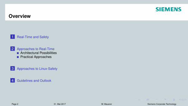
1 Real-Time and Safety
2 Approaches to Real-TimeArchitectural PossibilitiesPractical Approaches
3 Approaches to Linux-Safety
4 Guidelines and Outlook
Page 2 31. Mai 2017 W. Mauerer Siemens Corporate Technology
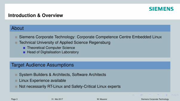
Introduction & Overview
About
Siemens Corporate Technology: Corporate Competence Centre Embedded LinuxTechnical University of Applied Science Regensburg
Theoretical Computer ScienceHead of Digitalisation Laboratory
Target Audience Assumptions
System Builders & Architects, Software ArchitectsLinux Experience availableNot necessarily RT-Linux and Safety-Critical Linux experts
Page 3 31. Mai 2017 W. Mauerer Siemens Corporate Technology
A journey through the worlds ofreal-time and safety
Page 4 31. Mai 2017 W. Mauerer Siemens Corporate Technology
Outline
1 Real-Time and Safety
2 Approaches to Real-TimeArchitectural PossibilitiesPractical Approaches
3 Approaches to Linux-Safety
4 Guidelines and Outlook
Page 5 31. Mai 2017 W. Mauerer Siemens Corporate Technology
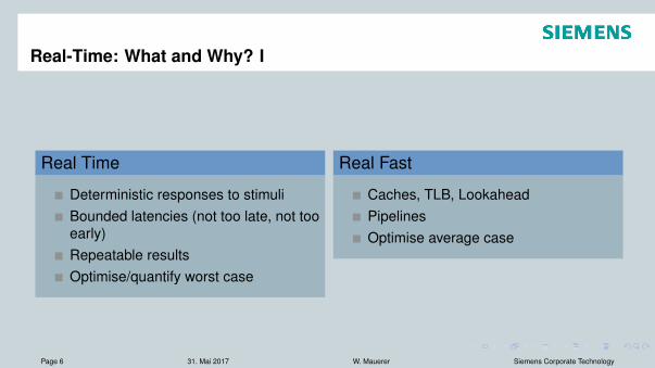
Real-Time: What and Why? I
Real Time
Deterministic responses to stimuliBounded latencies (not too late, not tooearly)Repeatable resultsOptimise/quantify worst case
Real Fast
Caches, TLB, LookaheadPipelinesOptimise average case
Page 6 31. Mai 2017 W. Mauerer Siemens Corporate Technology

Real-Time: What and Why? II
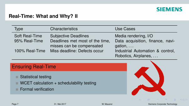
Type Characteristics Use Cases
Soft Real-Time Subjective Deadlines Media rendering, I/O95% Real-Time Deadlines met most of the time,
misses can be compensatedData acquisition, finance, navi-gation, . . .
100% Real-Time Miss deadline: Defects occur Industrial Automation & control,Robotics, Airplanes, . . .
Ensuring Real-Time
Statistical testingWCET calculation + schedulability testingFormal verification
Page 7 31. Mai 2017 W. Mauerer Siemens Corporate Technology
Real-Time: What and Why? II
Type Characteristics Use Cases
Soft Real-Time Subjective Deadlines Media rendering, I/O95% Real-Time Deadlines met most of the time,
misses can be compensatedData acquisition, finance, navi-gation, . . .
100% Real-Time Miss deadline: Defects occur Industrial Automation & control,Robotics, Airplanes, . . .
Ensuring Real-Time
Statistical testingWCET calculation + schedulability testingFormal verification
Page 7 31. Mai 2017 W. Mauerer Siemens Corporate Technology
Safety: What and Why?
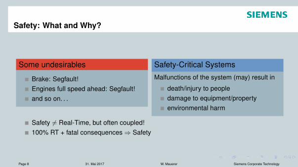
Some undesirables
Brake: Segfault!Engines full speed ahead: Segfault!and so on. . .
Safety-Critical SystemsMalfunctions of the system (may) result in
death/injury to peopledamage to equipment/propertyenvironmental harm
Safety 6= Real-Time, but often coupled!100% RT + fatal consequences ) Safety
Page 8 31. Mai 2017 W. Mauerer Siemens Corporate Technology
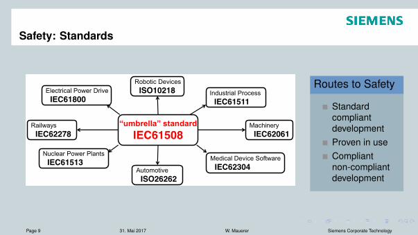
Safety: Standards
Challenge:
Electrical Power Drive IEC61800
Nuclear Power Plants IEC61513 Medical Device Software
IEC62304
Railways IEC62278
Industrial Process IEC61511
Robotic Devices ISO10218
Machinery IEC62061
Automotive ISO26262
“umbrella” standard IEC61508
Routes to Safety
StandardcompliantdevelopmentProven in useCompliantnon-compliantdevelopment
Page 9 31. Mai 2017 W. Mauerer Siemens Corporate Technology
Outline
1 Real-Time and Safety
2 Approaches to Real-TimeArchitectural PossibilitiesPractical Approaches
3 Approaches to Linux-Safety
4 Guidelines and Outlook
Page 10 31. Mai 2017 W. Mauerer Siemens Corporate Technology
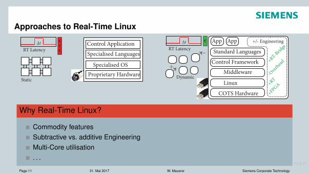
Approaches to Real-Time Linux
Middleware
COTS Hardware
App App
Standard LanguagesControl Framework
Linux
RT LatencyΔt €
+RT
+FPGA
-Over
head+RT-Brid
ge+/- Engineering
Specialised Languages
Proprietary Hardware
Control Application
Specialised OS
Static
+RT-Net
€€€
RT LatencyΔt
Dynamic
-+
Why Real-Time Linux?
Commodity featuresSubtractive vs. additive EngineeringMulti-Core utilisation. . .
Page 11 31. Mai 2017 W. Mauerer Siemens Corporate Technology
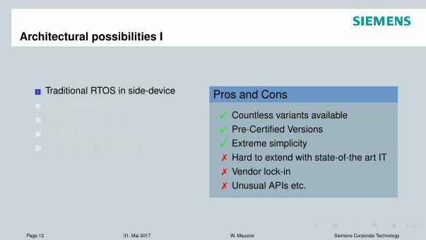
Architectural possibilities I
1 Traditional RTOS in side-device2 RT-Enhanced Kernel3 Separation Kernel4 Co-Kernel5 Asymmetric Multiprocessing
Pros and Cons
3 Countless variants available3 Pre-Certified Versions3 Extreme simplicity7 Hard to extend with state-of-the art IT7 Vendor lock-in7 Unusual APIs etc.
Page 12 31. Mai 2017 W. Mauerer Siemens Corporate Technology
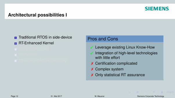
Architectural possibilities I
1 Traditional RTOS in side-device2 RT-Enhanced Kernel3 Separation Kernel4 Co-Kernel5 Asymmetric Multiprocessing
Pros and Cons
3 Leverage existing Linux Know-How3 Integration of high-level technologies
with little effort7 Certification complicated7 Complex system7 Only statistical RT assurance
Page 12 31. Mai 2017 W. Mauerer Siemens Corporate Technology
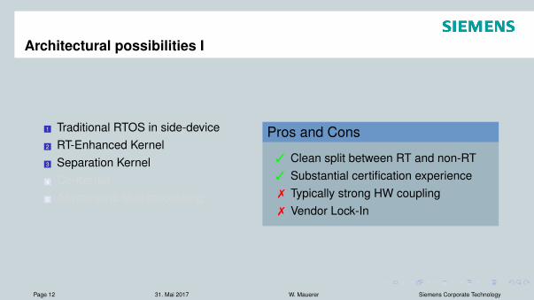
Architectural possibilities I
1 Traditional RTOS in side-device2 RT-Enhanced Kernel3 Separation Kernel4 Co-Kernel5 Asymmetric Multiprocessing
Pros and Cons
3 Clean split between RT and non-RT3 Substantial certification experience7 Typically strong HW coupling7 Vendor Lock-In
Page 12 31. Mai 2017 W. Mauerer Siemens Corporate Technology
Architectural possibilities I
1 Traditional RTOS in side-device2 RT-Enhanced Kernel3 Separation Kernel4 Co-Kernel5 Asymmetric Multiprocessing
Pros and Cons
3 Clean split between RT and non-RT3 Ressource efficient7 Non-standard maintenance efforts7 Implicit couplings
Page 12 31. Mai 2017 W. Mauerer Siemens Corporate Technology
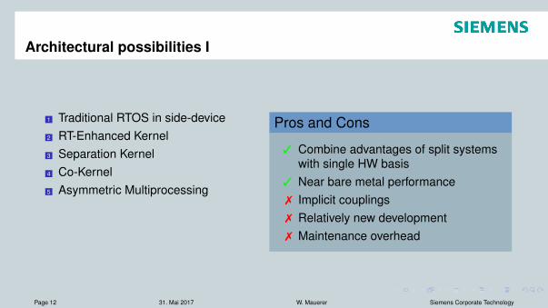
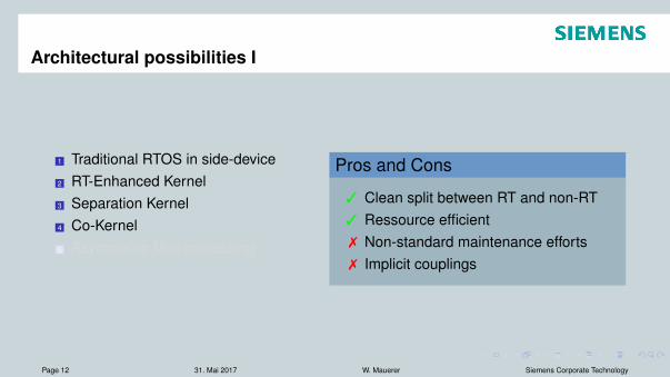
Architectural possibilities I
1 Traditional RTOS in side-device2 RT-Enhanced Kernel3 Separation Kernel4 Co-Kernel5 Asymmetric Multiprocessing
Pros and Cons
3 Combine advantages of split systemswith single HW basis
3 Near bare metal performance7 Implicit couplings7 Relatively new development7 Maintenance overhead
Page 12 31. Mai 2017 W. Mauerer Siemens Corporate Technology
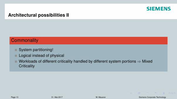
Architectural possibilities II
Commonality
System partitioning!Logical instead of physicalWorkloads of different criticality handled by different system portions ) MixedCriticality
Page 13 31. Mai 2017 W. Mauerer Siemens Corporate Technology
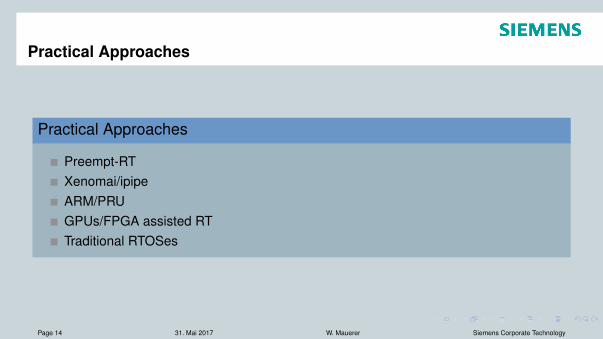
Practical Approaches
Practical Approaches
Preempt-RTXenomai/ipipeARM/PRUGPUs/FPGA assisted RTTraditional RTOSes
Page 14 31. Mai 2017 W. Mauerer Siemens Corporate Technology
Preempt-RT I
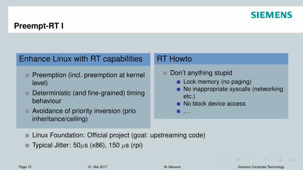
Enhance Linux with RT capabilities
Preemption (incl. preemption at kernellevel)Deterministic (and fine-grained) timingbehaviourAvoidance of priority inversion (prioinheritance/ceiling)
RT Howto
Don’t anything stupidLock memory (no paging)No inappropriate syscalls (networkingetc.)No block device access. . .
Linux Foundation: Official project (goal: upstreaming code)Typical Jitter: 50µs (x86), 150 µs (rpi)
Page 15 31. Mai 2017 W. Mauerer Siemens Corporate Technology
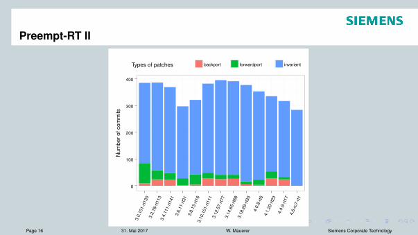
Preempt-RT II
0
100
200
300
400
3.0.
101-
rt130
3.2.
78-rt
113
3.4.
111-
rt141
3.6.
11-rt
313.
8.13
-rt16
3.10
.101
-rt11
13.
12.5
7-rt7
73.
14.6
5-rt6
83.
18.2
9-rt3
04.
0.8-
rt64.
1.20
-rt23
4.4.
9-rt1
74.
6-rc
7-rt1
Stack Version
Num
bero
fcom
mits
Types of patches backport forwardport invariant
Page 16 31. Mai 2017 W. Mauerer Siemens Corporate Technology
Preempt-RT III: Pros and Cons
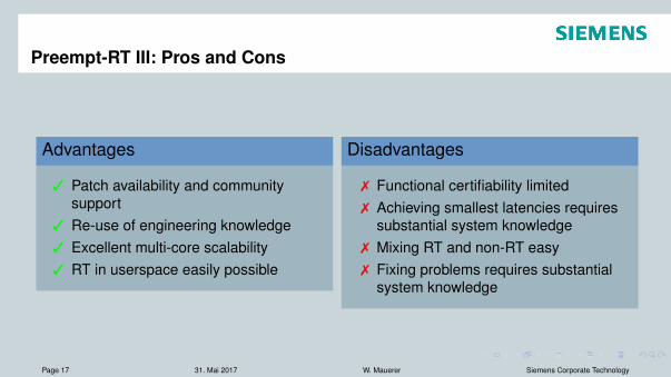
Advantages
3 Patch availability and communitysupport
3 Re-use of engineering knowledge3 Excellent multi-core scalability3 RT in userspace easily possible
Disadvantages
7 Functional certifiability limited7 Achieving smallest latencies requires
substantial system knowledge7 Mixing RT and non-RT easy7 Fixing problems requires substantial
system knowledge
Page 17 31. Mai 2017 W. Mauerer Siemens Corporate Technology
Xenomai 3.0 I
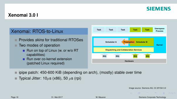
Xenomai: RTOS-to-Linux
Provides skins for traditional RTOSesTwo modes of operation
Run on top of Linux (w. or w/o RTcapabilities)Run over co-kernel extension(patched Linux required)
Kernel
Hardware
Scheduler A
Userspace
ProcessTask
Scheduler B
Dispatching and Collaboration Services
Task
IRQ
Task Task Task
Preemption
IRQ IRQ IRQ
ipipe patch: 450-600 KiB (depending on arch), (mostly) stable over timeTypical Jitter: 10µs (x86), 50 µs (rpi)
Image source: Siemens AG, CC BY-SA 3.0
Page 18 31. Mai 2017 W. Mauerer Siemens Corporate Technology
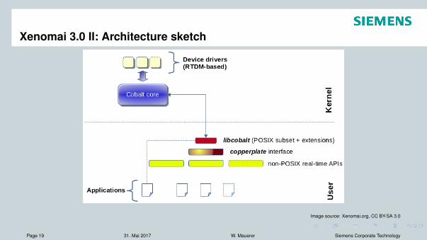
Xenomai 3.0 II: Architecture sketch
Image source: Xenomai.org, CC BY-SA 3.0
Page 19 31. Mai 2017 W. Mauerer Siemens Corporate Technology
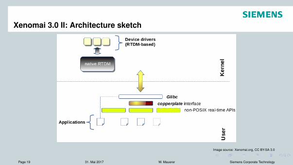
Xenomai 3.0 II: Architecture sketch
Image source: Xenomai.org, CC BY-SA 3.0
Page 19 31. Mai 2017 W. Mauerer Siemens Corporate Technology
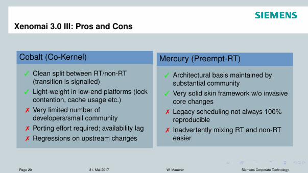
Xenomai 3.0 III: Pros and Cons
Cobalt (Co-Kernel)
3 Clean split between RT/non-RT(transition is signalled)
3 Light-weight in low-end platforms (lockcontention, cache usage etc.)
7 Very limited number ofdevelopers/small community
7 Porting effort required; availability lag7 Regressions on upstream changes
Mercury (Preempt-RT)
3 Architectural basis maintained bysubstantial community
3 Very solid skin framework w/o invasivecore changes
7 Legacy scheduling not always 100%reproducible
7 Inadvertently mixing RT and non-RTeasier
Page 20 31. Mai 2017 W. Mauerer Siemens Corporate Technology
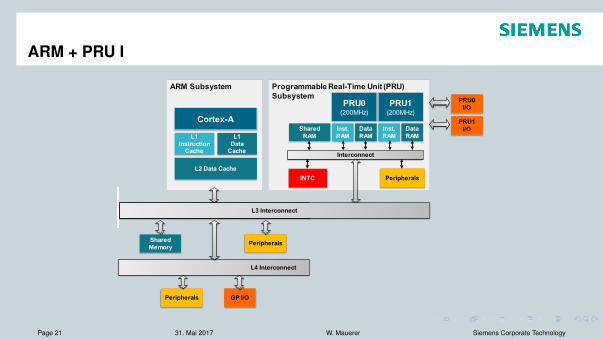
ARM + PRU I
Programmable Real-Time Unit (PRU)
Subsystem
Interconnect
INTC Peripherals
PRU0
I/O
Inst.
RAM
Shared
RAM
Data
RAM
Inst.
RAM
Data
RAM
PRU1
I/O
Shared
Memory Peripherals
Peripherals GP I/O
L4 Interconnect
ARM Subsystem
Cortex-A
L1
Instruction
Cache
L1
Data
Cache
L2 Data Cache
PRU0
(200MHz)
PRU1
(200MHz)
L3 Interconnect L3 Interconnect
Page 21 31. Mai 2017 W. Mauerer Siemens Corporate Technology
ARM + PRU II
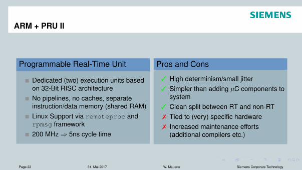
Programmable Real-Time Unit
Dedicated (two) execution units basedon 32-Bit RISC architectureNo pipelines, no caches, separateinstruction/data memory (shared RAM)Linux Support via remoteproc andrpmsg framework200 MHz ) 5ns cycle time
Pros and Cons
3 High determinism/small jitter3 Simpler than adding µC components to
system3 Clean split between RT and non-RT7 Tied to (very) specific hardware7 Increased maintenance efforts
(additional compilers etc.)
Page 22 31. Mai 2017 W. Mauerer Siemens Corporate Technology
Real-Time GPU/FPGA assisted Computing
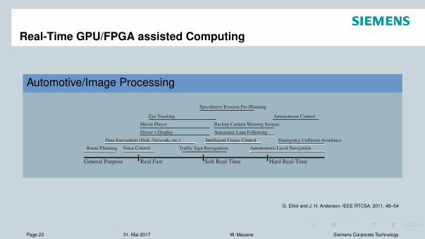
Automotive/Image Processing
General Purpose Real Fast Soft Real-Time Hard Real-Time
Driver’s Display Automatic Lane Following
Movie Player Backup Camera Warning System
Speculative Evasion Pre-Planning
Eye Tracking
Route Planning Voice Control Traffic Sign Recognition Autonomous Local Navigation
Data Encryption (Disk, Network, etc.) Emergency Collision AvoidanceIntelligent Cruise Control
Autonomous Control
Figure 2: Spectrum of possible temporal requirements for a number of automotive applications that may utilize a GPU.Each feature may cross domains, as indicated by the line beneath each feature name.
note that the use of GPUs appears to be the only eco-nomically feasible solution able to meet the processingrequirements of advanced driver-assist and autonomousfeatures in future automotive applications. Unfortunately,there are obstacles created by current GPU technologythat must be overcome before GPUs can be incorporatedinto real-time systems. In this paper we discuss severalof these obstacles and present a summary of solutions wehave found through our research to date. We hope to en-gage the real-time and cyber-physical systems communi-ties to identify additional applications where the use ofGPUs may be beneficial or even necessary. Through fur-ther research and the development of a breadth of appli-cations, we hope to inspire GPU manufactures to incor-porate features into their products to improve real-timebehaviors.
This paper is organized as follows. In the next sec-tion, we present several applications where GPUs maybe beneficial in real-time systems. In Sec. 3, we presentthe unique constraints imposed by current GPU technol-ogy that pose challenges to the use of GPUs in real-timesystems. In Sec. 4, we present a summary of solutionsthat we have developed that address several of these con-straints and allow GPUs to be used in real-time systems.In Sec. 5, we present future directions for our research anddiscuss what changes may be necessary in current GPUtechnology to better support real-time systems. Finally,in Sec. 6, we conclude with remarks on the field of real-time GPUs.
2 Real-Time GPU ApplicationsThere are a number of real-time domains where GPUsmay be applied. For example, a GPU can efficientlycarry out many digital signal processing operations suchas multidimensional FFTs and convolution as well as ma-trix operations such as factorization on data sets of upto several gigabytes in size. These operations, coupled
with other GPU-efficient algorithms, can be used in med-ical imaging and video processing, where real-time con-straints are common. Additionally, a particularly com-pelling application for real-time GPUs is that of automo-biles.
GPUs can be used to implement a number of systemfeatures in the automotive domain. For user interface fea-tures, a GPU may be used to realize rich displays for thevehicle operator and to implement responsive voice-basedcontrols [16], all while possibly driving video entertain-ment displays for other passengers simultaneously. Fur-ther, a GPU can also be used to track the eyes of thevehicle operator [24]. Such tracking could be used toimplement a number of safety features. Real-time ap-plications for GPUs in automobiles become even moreapparent when we consider driver-assist and autonomousvehicle features. In these platforms, multiple streamsof data from video feeds, laser range sensors, and radarcan be processed and correlated to provide environmen-tal data for a number of vehicle functions. This data canbe used for automatic sign recognition [27], local naviga-tion (such as lane following), and obstacle avoidance [29].GPUs are well suited to handle this type of workload sincethese sensors generate enormous amounts of data. Indeed,GPUs are likely the only efficient and cost-effective solu-tion. Moreover, these are clearly safety-critical applica-tions where real-time constraints are important.
Fig. 2 depicts a number of automobile features thatcould make use of a GPU. These features are plottedalong a spectrum of temporal requirements showing ourview of the relative need for real-time performance. Thespectrum is broken up into four regions: general-purpose,“real-fast,”2 soft real-time, and hard real-time. Features inthe general-purpose region are those that could possiblybe supported by general-purpose scheduling algorithms,though may still be a part of a real-time system. The “real-fast” region captures applications that may have general
2The term “real-fast” is borrowed from Paul McKenny [26].
G. Elliot and J. H. Anderson, IEEE RTCSA, 2011, 48–54
Page 23 31. Mai 2017 W. Mauerer Siemens Corporate Technology
GPU Architecture
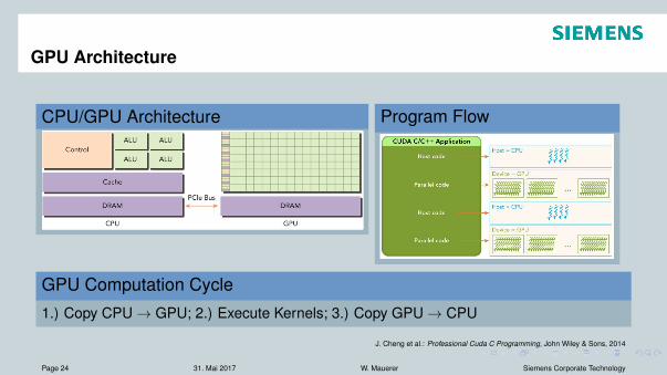
CPU/GPU Architecture
Abb. 1.1: Unterschied zwischen einer CPU- und GPU-Architektur(Quelle: [CGM14], Seite 9)
Für die Entwicklung der Bibliothek und den Test der Algorithmen wurden die TeslaK20c und das Jetson TK1 Entwicklungsboard verwendet. Beide basieren aus der inAbbildung 1.2 dargestellten Kepler1 Architektur.
Der L2-Cache entspricht dem globalen Speicher, der von allen laufenden Threads aufder GPU geschrieben und gelesen werden kann. Er ist der größte auf der GPU vor-handene Speicher, besitzt allerdings auch die längsten Zugriffszeiten. Um der GPUDaten für die Ausführung bereit zu stellen, müssen diese initial vom RAM Speicher derCPU über den entsprechenden Speicherbus in den globalen Speicher der GPU kopiertwerden. Nach einer Berechnung durch die GPU werden alle Ergebnisse wieder in denglobalen Speicher abgelegt, wodurch diese von hier wieder in den RAM Speicher derCPU transferiert werden können. Es ist anzumerken, dass je nach Anbindung der GPUdie Transferraten des Speicherbusses sehr lang sein können, wodurch Daten nicht öfterals nötig zwischen GPU und CPU kopiert werden sollten.
Eine GPU auf Basis der Kepler Architektur besteht wiederum aus mehreren Multipro-zessoren (SMX), deren Aufbau in Abbildung 1.3 dargestellt ist.
Jeder dieser Multiprozessoren besitzt einen kleineren, schnelleren L1- und Read-Ony-Cache, eigene Register, Shedduler, Dispatcher, mehrere Load/Store Units (LD/ST), Dou-ble-Precision Units (DP Unit), Special-Function Units (SFU) und eine hohe Anzahl anSingle-Percision Units (Cores). Da hier nur ein kleiner Einblick in die Architektur vonGPUS gegeben werden kann, sei für eine genauere Beschreibung der einzelnen Kompo-nenten zum Beispiel auf [CGM14] verwiesen.
Interessant ist jedoch der L1-Cache eines solchen Multiprozessors. Dieser ist zwar klei-ner als der globale L2-Cache, besitzt aber deutlich schnellere Zugriffszeiten als die-ser, wodurch er ausgezeichnet als Zwischenspeicher von temporären Ergebnissen einesThreads dienen kann, wie später noch gezeigt wird. Da dieser Speicher jedoch von al-len Kernen eines Multiprozessors verwendet wird, muss darauf geachtet werden, dasspro Kern nicht zu viel Speicher benötigt wird, da ansonsten die Anzahl an ausführbaren
1http://www.nvidia.de/object/nvidia-kepler-de.html
2
Program Flow
Abb. 1.4: Beispielhafter Ablauf eine Cuda-Programms(Quelle: [CGM14], Seite 25)
1.2 Cuda
CUDA ist ein von NVIDIA eigens für ihre GPUS bereitgestelltes Framework zur Pro-grammierung von Grafikprozessoren. Das bedeutet, wo OPENCL prinzipiell für alleArten von GPUS verschiedener Hersteller verwendet werden kann, zielt CUDA aus-schließlich auf die Programmierung von NVIDA-GPUS ab.
Nichts desto trotz besteht die Möglichkeit, GPUS der Firma NVIDIA mit Hilfe vonOPENCL zu programmieren. Dies wird aber von OPENCL nur stiefmütterlich unter-stützt und erreicht zudem auch nicht die Performance, die mit dem eigens für NVIDA-GPUS entwickelten CUDA-Framework erreicht werden kann.
Aus diesem Grund wurde CUDA für die Implementierung verwendet, was aber nichtausschließt, das die vorgestellten Algorithmen für andere GPUS mit ein wenig Aufwandauf OPENSSL portiert werden könnten. Dies ist jedoch nicht Teil dieser Arbeit.
CUDA stellt eine Erweiterung des C/C++-Syntax dar, indem dieser durch spezielle Schlüs-selwörter ergänzt wurde. Zudem gibt es bereits CUDA-Wrapper für die gängigsten Pro-grammiersprachen, wie zum Beispiel Java, Python, Perl und .NET, wodurch der Einstiegin die Programmierung mit CUDA sehr einfach gestaltet ist. Für die entwickelte Biblio-thek erfolgten die CUDA-Umsetzung jedoch ausschließlich mit Hilfe des erweitertenC++-Syntax.
Wie in Abbildung 1.4 dargestellt, enthält ein CUDA-Programm eine Kombination ausCPU- und GPU-Code und stellt somit ein heterogenes Programmiermodell dar.
Wird dieser Code mit dem NVCC Compiler aus dem CUDA-Framework kompiliert, sowird einerseits Maschinencode für die CPU mittels des verwendeten C++ Compilers
5
GPU Computation Cycle1.) Copy CPU ! GPU; 2.) Execute Kernels; 3.) Copy GPU ! CPU
J. Cheng et al.: Professional Cuda C Programming, John Wiley & Sons, 2014
Page 24 31. Mai 2017 W. Mauerer Siemens Corporate Technology
GPU/FPGA assisted RT: Problems
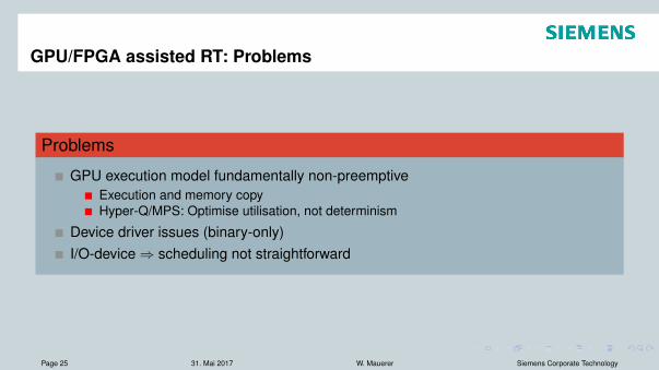
Problems
GPU execution model fundamentally non-preemptiveExecution and memory copyHyper-Q/MPS: Optimise utilisation, not determinism
Device driver issues (binary-only)I/O-device ) scheduling not straightforward
Page 25 31. Mai 2017 W. Mauerer Siemens Corporate Technology
Ressource Arbitration
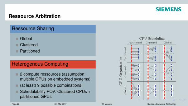
Ressource Sharing
GlobalClusteredPartitioned
Heterogenous Computing
2 compute ressources (assumption:multiple GPUs on embedded systems)(at least) 9 possible combinations!Schedulability POV: Clustered CPUs +partitioned GPUs
Parameter Descriptionm number of system CPUsh number of system GPUsc CPU cluster sizeg GPU cluster sizeTG set of all GPU-using tasksTC set of all CPU-only tasksecpui Ti’s provisioned CPU execution timeegpui Ti’s provisioned GPU execution time
qcpui
total CPU execution time withinTi’s GPU critical section
zIi size of Ti’s GPU input data (bytes)zOi size of Ti’s GPU output data (bytes)zSi size of Ti’s inter-job GPU state data (bytes)bi upperbound on blocking for Ti
Table I: Important notation.
one arbitrary GPU in its GPU cluster. egpui , zIi , zOi , and
zSi are zero for Ti ∈ TC . The term bi denotes an upper-bound on the time Ti,j may be blocked due to lock requests(for presentation simplicity, we assume tasks share no otherresources, but this is not a GPUSync requirement). We derivevalues for bi in Appendix B. Finally, Ti’s utilization is givenby ui ! (ecpu
i + egpui + xmit(zIi , zOi , zSi ))/pi, and the task set
utilization is U ! !ni=1 ui.
We refer back to the parameters summarized in Table I.Example. If we assume that the GPU usage pattern illus-trated in Fig. 3 represents the entire execution sequence of ajob Ti,j , then ecpu
i = (t2−t0)+(t4−t3)+(t6−t5)+(t9−t7),egpui = t5−t4, qcpu
i = (t2−t1)+(t4−t3)+(t6−t5)+(t8−t7),and xmit(zIi , zOi , zSi ) = (t3 − t2) + (t7 − t6) (assumingzSi = 0, i.e. the job has no state to migrate between GPUs).
B. GPUSync Structure
It helps to refer to concrete system configurations in describ-ing GPUSync, so let us define several such configurations.Fig. 4 depicts a matrix of several high-level CPU/GPUconfigurations for a 12-CPU, 8-GPU system, which we alsouse in Secs. IV and V. We refer to each cell in Fig. 4 using acolumn-major tuple, with the indices P , C, and G denotingpartition, clustered, and global choices, respectively. Thetuple (P, P ) refers to the top-left corner—a configurationwith partitioned CPUs and GPUs. Likewise, (G,C) indicatesthe right-most middle cell—globally scheduled CPUs withclustered GPUs. We use the wildcard ∗ to refer to anentire row or column: e.g., (P, ∗) refers to the left-mostcolumn—all configurations with partitioned CPUs. Withineach cell, individual CPUs and GPUs are shown on theleft and right, respectively. Dashed boxes delineate CPU andGPU clusters (no boxes are used in partitioned cases). Thesolid lines depict the association between CPUs and GPUs.For example, the solid lines in (C,C) indicate that two GPUclusters are wholly assigned to each CPU cluster. Finally,the horizontal dashed line across each cell denotes theNUMA boundary of the system. Offline, tasks are assignedto CPU and GPU clusters in accordance with the desired
Partitioned Clustered Global
Part
itio
ned
Clu
ster
edG
lobal
CPU Scheduling
GP
U O
rganiz
ation
Figure 4: Concrete configurations.
configuration.GPUSync uses a two-level nested locking structure: an
outermost token lock to allocate GPUs to jobs and innermostengine locks to arbitrate access to GPU engines. This isdepicted in Fig. 5. In Step A (or time t1 in Fig. 3), thejob requests a token from the GPU allocator responsible formanaging the GPUs in the job’s GPU cluster. The GPUallocator determines which token—and by extension, whichGPU—should be allocated to the request. The requestingjob may access the assigned GPU once it receives a tokenin Step B. In Step C, the job competes with other token-holding jobs for GPU engines; access is arbitrated by theengine locks. A job may only issue GPU operations on itsassigned GPU after acquiring its needed engine locks in StepD. For example, an engine lock must be acquired at times t2,t4, and t6 in Fig. 3. With the exception of P2P migrations,a job cannot hold more than one engine lock at a time.
GPUSync can be configured to use different lockingprotocols to manage tokens and engines. In this paper, weconfigure GPUSync to use protocols known to offer asymp-totically optimal blocking bounds under FL scheduling. Wenow describe the two locking levels in more detail. Weprovide blocking analysis in Appendix B.
Token lock. Each cluster of g GPUs is managed byone GPU allocator. We associate ρ tokens (a configurable
CE0IN
CE0OUT
EE0
GPUAllocator
request
Engine Locks
GPUg–1GPU0
Figure 5: High-level design of GPUSync.
263
G. Elliot and J. H. Anderson, IEEE RTCSA, 2011, 48–54Page 26 31. Mai 2017 W. Mauerer Siemens Corporate Technology
GPU: Scheduling Practicalities
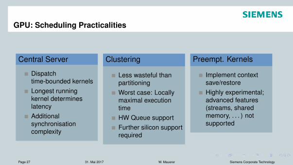
Central Server
Dispatchtime-bounded kernelsLongest runningkernel determineslatencyAdditionalsynchronisationcomplexity
Clustering
Less wasteful thanpartitioningWorst case: Locallymaximal executiontimeHW Queue supportFurther silicon supportrequired
Preempt. Kernels
Implement contextsave/restoreHighly experimental;advanced features(streams, sharedmemory, . . . ) notsupported
Page 27 31. Mai 2017 W. Mauerer Siemens Corporate Technology
Small RTOS I
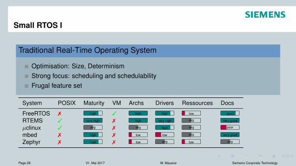
Traditional Real-Time Operating System
Optimisation: Size, DeterminismStrong focus: scheduling and schedulabilityFrugal feature set
System POSIX Maturity VM Archs Drivers Ressources Docs
FreeRTOS 7 high 3 high high low good
RTEMS 3 very high 7 high very high avg very good
µclinux 3 avg 7 avg high avg poor
mbed 7 high 7 low low avg very good
Zephyr 7 high 7 low avg low avg
Page 28 31. Mai 2017 W. Mauerer Siemens Corporate Technology
Small RTOS II
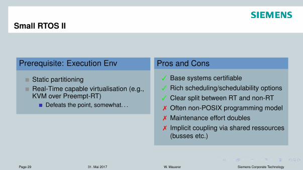
Prerequisite: Execution Env
Static partitioningReal-Time capable virtualisation (e.g.,KVM over Preempt-RT)
Defeats the point, somewhat. . .
Pros and Cons
3 Base systems certifiable3 Rich scheduling/schedulability options3 Clear split between RT and non-RT7 Often non-POSIX programming model7 Maintenance effort doubles7 Implicit coupling via shared ressources
(busses etc.)
Page 29 31. Mai 2017 W. Mauerer Siemens Corporate Technology
Outline
1 Real-Time and Safety
2 Approaches to Real-TimeArchitectural PossibilitiesPractical Approaches
3 Approaches to Linux-Safety
4 Guidelines and Outlook
Page 30 31. Mai 2017 W. Mauerer Siemens Corporate Technology
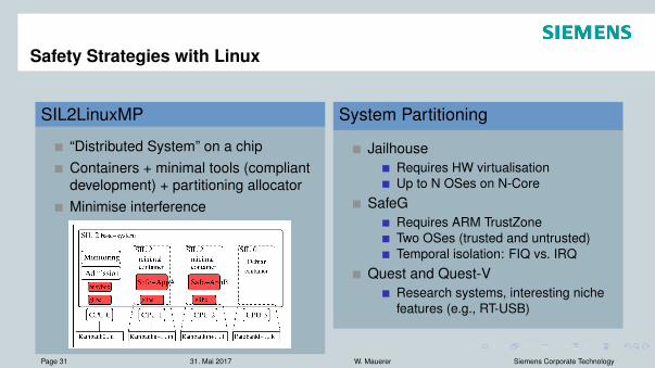
Safety Strategies with Linux
SIL2LinuxMP
“Distributed System” on a chipContainers + minimal tools (compliantdevelopment) + partitioning allocatorMinimise interference
System Partitioning
JailhouseRequires HW virtualisationUp to N OSes on N-Core
SafeGRequires ARM TrustZoneTwo OSes (trusted and untrusted)Temporal isolation: FIQ vs. IRQ
Quest and Quest-VResearch systems, interesting nichefeatures (e.g., RT-USB)
Image Source: N. McGuire, GNU/Linux for safety-related systems – SIL2LinuxMP, FOSDEM 2016Page 31 31. Mai 2017 W. Mauerer Siemens Corporate Technology
Safety Strategies for Linux
Safety and Linux
Partition system in various waysMixed Criticality : Combine critical & uncritical workloads
Page 32 31. Mai 2017 W. Mauerer Siemens Corporate Technology
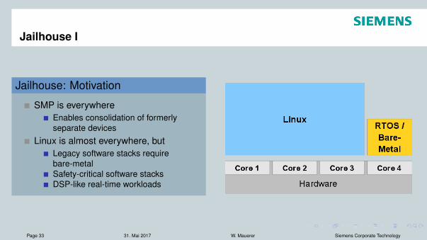
Jailhouse I
Jailhouse: Motivation
SMP is everywhereEnables consolidation of formerlyseparate devices
Linux is almost everywhere, butLegacy software stacks requirebare-metalSafety-critical software stacksDSP-like real-time workloads
Page 33 31. Mai 2017 W. Mauerer Siemens Corporate Technology
Jailhouse II
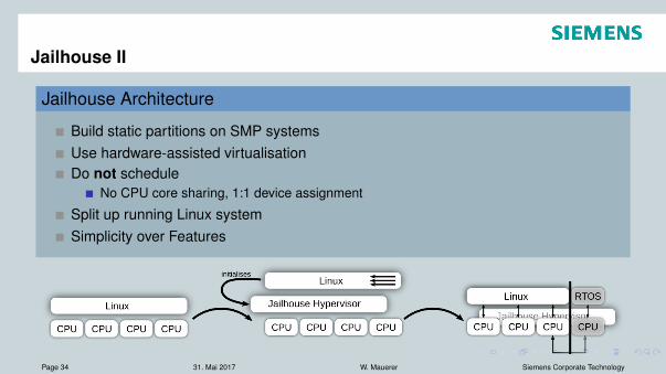
Jailhouse Architecture
Build static partitions on SMP systemsUse hardware-assisted virtualisationDo not schedule
No CPU core sharing, 1:1 device assignment
Split up running Linux systemSimplicity over Features
Page 34 31. Mai 2017 W. Mauerer Siemens Corporate Technology
Jailhouse: Challenges
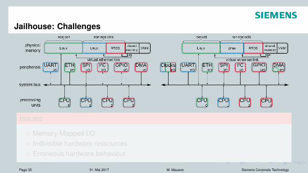
Issues
Memory-Mapped I/OIndivisible hardware ressourcesErroneous hardware behaviour
Page 35 31. Mai 2017 W. Mauerer Siemens Corporate Technology
Jailhouse: Challenges
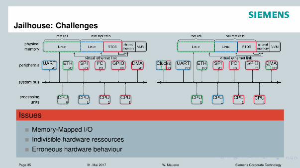
Issues
Memory-Mapped I/OIndivisible hardware ressourcesErroneous hardware behaviour
Page 35 31. Mai 2017 W. Mauerer Siemens Corporate Technology
Jailhouse: Impact?
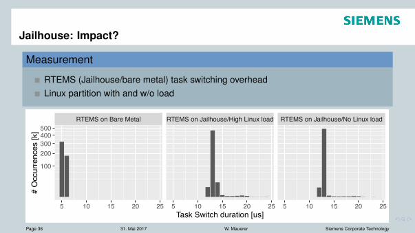
Measurement
RTEMS (Jailhouse/bare metal) task switching overheadLinux partition with and w/o load
RTEMS on Bare Metal RTEMS on Jailhouse/High Linux load RTEMS on Jailhouse/No Linux load
100
200300400500
5 10 15 20 25 5 10 15 20 25 5 10 15 20 25Task Switch duration [us]
# O
ccur
renc
es [k
]
Page 36 31. Mai 2017 W. Mauerer Siemens Corporate Technology

Outline
1 Real-Time and Safety
2 Approaches to Real-TimeArchitectural PossibilitiesPractical Approaches
3 Approaches to Linux-Safety
4 Guidelines and Outlook
Page 37 31. Mai 2017 W. Mauerer Siemens Corporate Technology
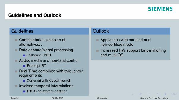
Guidelines and Outlook
Guidelines
Combinatorial explosion ofalternatives. . .Data capture/signal processing
Jailhouse, PRUAudio, media and non-fatal control
Preempt-RTReal-Time combined with throughoutrequirements
Xenomai with Cobalt kernelInvolved temporal interrelations
RTOS on system partition
Outlook
Appliances with certified andnon-certified modeIncreased HW support for partitioningand multi-OS
Page 38 31. Mai 2017 W. Mauerer Siemens Corporate Technology

Thanks for your interest!
Page 39 31. Mai 2017 W. Mauerer Siemens Corporate Technology