Embed Size (px)
Citation preview

The Materials Research Society (MRS)
XXII INTERNATIONAL MATERIALS RESEARCH CONGRESS 2013 NACE International Congress-Mexican Section
Sociedad Mexicana de Materiales Cancún, México
Edna Prieto García Centro de Investigación en Materiales Avanzados, S.C. Chihuahua, Chih., 31109 México Tel: (614)4993017 E-mail: [email protected] Gerardo Valle Corona Centro de Investigación en Materiales Avanzados, S.C. Chihuahua, Chih., 31109 México Tel: (614)4993017 E-mail: [email protected] Luis Carlos Ortiz Luévano Centro de Investigación en Materiales Avanzados, S.C. Chihuahua, Chih., 31109 México Tel: (639)1351338 E-mail: [email protected] Alberto Martínez Villafañe Centro de Investigación en Materiales Avanzados, S.C. Chihuahua, Chih., 31109 México Tel: (614)4391145 E-mail: [email protected]
Ivanovich Estrada Guel Centro de Investigación en Materiales Avanzados, S.C. Chihuahua, Chih., 31109 México Tel: (614)4394816 E-mail: [email protected] José Martin Herrera Ramírez Centro de Investigación en Materiales Avanzados, S.C. Chihuahua, Chih., 31109 México Tel: (614)4394827 E-mail: [email protected] Roberto Martínez Sánchez Centro de Investigación en Materiales Avanzados, S.C. Chihuahua, Chih., 31109 México Tel: (614)4391146 E-mail: [email protected]
XXII International Materials Research Congress 2013 NACE International Congress-Mexican Section
2
Página
MICROSTRUCTURAL CHARACTERIZATION OF A NI BASED ALLOY SYNTHETIZED BY MECHANICAL ALLOYING
Abstract
In this Work we describe the microstructural effect of the conventional sintering in the mechanical properties of a Ni based alloy synthesized by mechanical alloying (MA). Raw materials were commercial cobalt, chromium and nickel pure powders supplied by Sigma-Aldrich. Compositions studied were Ni60Co30Al10, Ni55Co35Al10, Ni60Co10Cr20Al10 and Ni55Co15Cr20Al10 in at. %. MA was performed using in a SPEX 8000 mill. An argon atmosphere was used to avoid oxidation and methanol was employed as the control agent process. Powders mixtures were milled for 5 and 20 h. Their morphology was analyzed using a JEOL JSM-5800 scanning electron microscopy. Variations in chemical composition were followed by EDS. Microhardness assessments in sintering samples was performed using Vickers scale, 10 indentation were done and the average value was reported. Results are discussed as a function of composition and milling time.
XXII International Materials Research Congress 2013 NACE International Congress-Mexican Section
3
Página
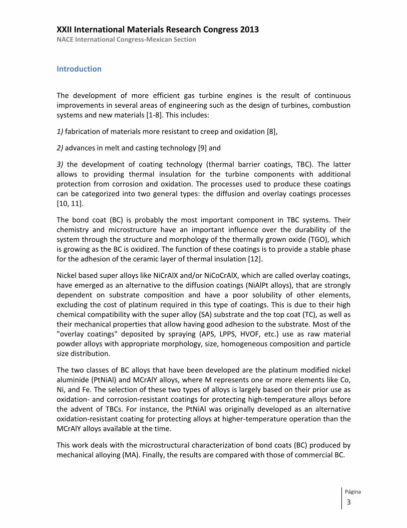
Introduction
The development of more efficient gas turbine engines is the result of continuous improvements in several areas of engineering such as the design of turbines, combustion systems and new materials [1-8]. This includes:
1) fabrication of materials more resistant to creep and oxidation [8],
2) advances in melt and casting technology [9] and
3) the development of coating technology (thermal barrier coatings, TBC). The latter allows to providing thermal insulation for the turbine components with additional protection from corrosion and oxidation. The processes used to produce these coatings can be categorized into two general types: the diffusion and overlay coatings processes [10, 11].
The bond coat (BC) is probably the most important component in TBC systems. Their chemistry and microstructure have an important influence over the durability of the system through the structure and morphology of the thermally grown oxide (TGO), which is growing as the BC is oxidized. The function of these coatings is to provide a stable phase for the adhesion of the ceramic layer of thermal insulation [12].
Nickel based super alloys like NiCrAlX and/or NiCoCrAlX, which are called overlay coatings, have emerged as an alternative to the diffusion coatings (NiAlPt alloys), that are strongly dependent on substrate composition and have a poor solubility of other elements, excluding the cost of platinum required in this type of coatings. This is due to their high chemical compatibility with the super alloy (SA) substrate and the top coat (TC), as well as their mechanical properties that allow having good adhesion to the substrate. Most of the "overlay coatings" deposited by spraying (APS, LPPS, HVOF, etc.) use as raw material powder alloys with appropriate morphology, size, homogeneous composition and particle size distribution.
The two classes of BC alloys that have been developed are the platinum modified nickel aluminide (PtNiAl) and MCrAlY alloys, where M represents one or more elements like Co, Ni, and Fe. The selection of these two types of alloys is largely based on their prior use as oxidation- and corrosion-resistant coatings for protecting high-temperature alloys before the advent of TBCs. For instance, the PtNiAl was originally developed as an alternative oxidation-resistant coating for protecting alloys at higher-temperature operation than the MCrAlY alloys available at the time.
This work deals with the microstructural characterization of bond coats (BC) produced by mechanical alloying (MA). Finally, the results are compared with those of commercial BC.

XXII International Materials Research Congress 2013 NACE International Congress-Mexican Section
4
Página
Experimental procedure
Elemental powders of Ni (purity 99.9%, -325 mesh), Co (purity 99.5%, -325 mesh), Al (purity 99.9%, -325 mesh) and Cr (purity 99.9%, -325 mesh) were used as the raw materials. The NiCoAl and NiCoCrAl powder mixtures were prepared by mixing different concentrations of elemental powders. Millings were performed in a high energy SPEX ball mill under an Ar atmosphere and the milling times were 5 and 20 h. The ball-to-powder weight ratio for all the experiments was 5:1 and methanol (1ml) was used as process control agent (PCA). Prior to milling, mixtures were blended for 5 minutes to obtain an homogenous mixing of powders. Table 1 shows the identification of processed and commercial powder mixtures as a function of the milling time. Mechanically alloyed (MA´ed) products were characterized by X-ray diffraction (XRD) in a Panalitical X’pert
diffractometer using a Cu cathode ( = 0.15406 nm). Analyses were carried out in the 2θ range of 20-110º. The step size and acquisition time were 0.02° and 5s, respectively. The crystallite size was calculated from the Sherrer’s equation. Analyses were performed in a JSM-5800LV scanning electron microscope (SEM) equipped with an energy dispersive spectrometer (EDS) operated at 20 kV. Finally, Vickers microhardness tests were measured under 100 g load with 10 s of dwell time on a FM-07 Micro Hardness tester. The reported value is the average obtained from 10 measurements. For comparison, two commercial products AMDRY were also characterized.
Table I. Identification of samples based on nominal composition (at. %) and milling time.
Sample Milling time (h) Identification
AMDRY 9954* _______ A9954
AMDRY 997* A997
Ni60Co30Al10 0 h 0a1
5 h 5a1
20 h 20a1
Ni60Cr20Co10Al10 0 h 0a2
5 h 5a2
20 h 20a2
* Commercial products
XXII International Materials Research Congress 2013 NACE International Congress-Mexican Section
5
Página
Results and Discussion
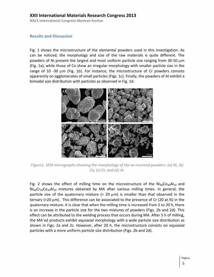
Fig. 1 shows the microstructure of the elemental powders used in this investigation. As can be noticed, the morphology and size of the raw materials is quite different. The
powders of Ni present the largest and most uniform particle size ranging from 30-50 m (Fig. 1a), while those of Co show an irregular morphology with smaller particle size in the
range of 10 -30 m (Fig. 1b). For instance, the microstructure of Cr powders consists apparently on agglomerates of small particles (Figs. 1c). Finally, the powders of Al exhibit a bimodal size distribution with particles as observed in Fig. 1d.
Figure1. SEM micrographs showing the morphology of the as-received powders: (a) Ni, (b) Co, (c) Cr, and (d) Al.
Fig. 2 shows the effect of milling time on the microstructure of the Ni60Co30Al10 and Ni60Cr20Co10Al10 mixtures obtained by MA after various milling times. In general, the
particle size of the quaternary mixture (< 20 m) is smaller than that observed in the
ternary (>20 m). This difference can be associated to the presence of Cr (20 at.%) in the quaternary mixture. It is clear that when the milling time is increased from 5 to 20 h, there is an increase in the particle size for the two mixtures of powders (Figs. 2b and 2d). This effect can be attributed to the welding process that occurs during MA. After 5 h of milling, the MA´ed products exhibit equiaxial morphology with a wide particle size distribution as shown in Figs. 2a and 2c. However, after 20 h, the microstructure consists on equiaxial particles with a more uniform particle size distribution (Figs. 2b and 2d).

XXII International Materials Research Congress 2013 NACE International Congress-Mexican Section
6
Página
Figure2. SEM micrographs showing the particles morphology of ternary and quaternary mixtures as a function of milling time: a) 5a1, b) 20a1, c) 5a2 and d) 20a2
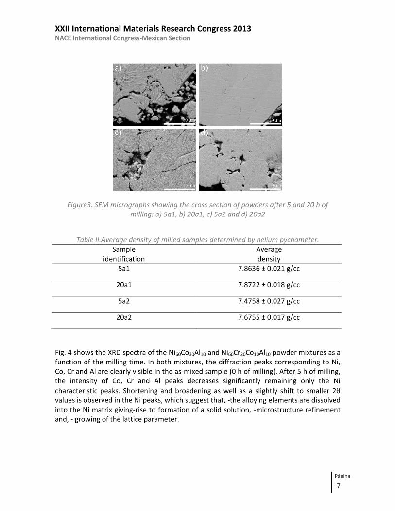
Fig. 3 shows the effect of milling time (5 and 20 h) on the microstructure of NiCoAl and NiCoCrAl powder mixtures. As can be observed, a quasi-lamellar structure is presented after short-time millings (5 h). This microstructure is typically observed in the early stages of MA for ductile components [13]. The results of EDS analyses show that this phase is rich in Co (Fig. 3a). Further milling results in more uniform microstructures as observed in Figs. 3b and 3d. It was also observed that the chemical composition is more homogeneous after 20 h of milling. This observation is supported by the results of EDS analyses. On the other hand, the presence of oxygen was not detected during milling process. This indicates that the oxidation was very low. By performing a density test by helium pycnometer technique, in which the gas used was nitrogen and small cell. 3 readings for each sample, it was observed that the different densities exhibit the samples as shown in Table II.
XXII International Materials Research Congress 2013 NACE International Congress-Mexican Section
7
Página
Figure3. SEM micrographs showing the cross section of powders after 5 and 20 h of milling: a) 5a1, b) 20a1, c) 5a2 and d) 20a2
Table II.Average density of milled samples determined by helium pycnometer.
Sample identification
Average density
5a1 7.8636 ± 0.021 g/cc
20a1 7.8722 ± 0.018 g/cc
5a2 7.4758 ± 0.027 g/cc
20a2 7.6755 ± 0.017 g/cc
Fig. 4 shows the XRD spectra of the Ni60Co30Al10 and Ni60Cr20Co10Al10 powder mixtures as a function of the milling time. In both mixtures, the diffraction peaks corresponding to Ni, Co, Cr and Al are clearly visible in the as-mixed sample (0 h of milling). After 5 h of milling, the intensity of Co, Cr and Al peaks decreases significantly remaining only the Ni
characteristic peaks. Shortening and broadening as well as a slightly shift to smaller 2 values is observed in the Ni peaks, which suggest that, -the alloying elements are dissolved into the Ni matrix giving-rise to formation of a solid solution, -microstructure refinement and, - growing of the lattice parameter.

XXII International Materials Research Congress 2013 NACE International Congress-Mexican Section
8
Página
20 40 60 80 100 120
¤
¤
a)
20h
5h
0h
Ni60Co30Al10 •Ni
Co
¤Al
2 (Degrees)
Inte
nsi
ty (
a.
u.)
¤¤
¤
••
••
•
20 40 60 80 100 120
¤
¤
b)
20h
5h
0h
Ni60Cr20Co10Al10 •Ni
Co
¤Al
Cr
2 (Degrees)
Inte
nsi
ty (
a.
u.)
¤¤
¤
•••
•
•
Figure4. XRD patterns of the a) Ni60Co30Al10 and b) Ni60Cr20Co10Al10 powder mixtures
after 5 and 20 h of milling. It is noteworthy that the crystal structure of Co powders is HCP in the as-mixed condition (0 h of milling). Therefore, after milling, either the HCP structure transforms to FCC or Co is dissolved into Ni matrix. As a result, the peak corresponding to Co HCP is no longer observed after 5 h (See Figs. 4a and 4b). This can be explained by the reduction on the particle size and accumulation of structural defects, as reported elsewhere [14, 15]. After 20 h of milling, the shortening of the Ni peaks and the displacement to lower angles are more evident indicating a variation on the lattice parameter. Additionally, an important effect on crystal size refinement was observed in samples containing Cr. The results of lattice parameter and crystal size calculated from XRD spectra are shown in Table III.

XXII International Materials Research Congress 2013 NACE International Congress-Mexican Section
9
Página
Table III. Crystallite size and lattice parameter of the milled powders Sample
identification
Crystallite size
(Å)
Lattice
parameter (nm)
0a1 559 0.352
5a1 123 0.352
20a1 84 0.354
0a2 559 0.352
5a2 63 0.353
20a2 34 0.355
Morphology and cross section microstructures of commercial AMDRY powders are shown in Fig. 5. As can be seen, the particles of A997 exhibit spherical morphology with sizes
ranging from 5-20 m (Fig. 5a). Furthermore, the cross section microstructure of this alloy shows a typical cast microstructure with gray-colored dendrite arms (Fig. 5b) and a continuous interdendritic phase with bright contrast. In the A9954 alloy, the particles present a section microstructure of A9954 shows a cast microstructure with gray-colored dendrite and a dark-grayed interdendritic phase. It is important to mention that these two phases identified by SEM and XRD were only observed in the commercial products. Therefore, it can be seen that the milled powders present a higher microstructural homogeneity. Table IV lists the chemical composition of these phases (determined by EDS) as well as their microstructural characteristics. In addition, Table IV shows the nominal composition of the commercial products used which can be related to the composition of the phases. Nevertheless, the presence of Ta or Y elements in the commercial products used in this work was not detected by SEM or XRD. It is also observed in both samples isolated porous
with sizes lower that 1m.

XXII International Materials Research Congress 2013 NACE International Congress-Mexican Section
10
Página
Figure5. SEM micrographs showing (a) the AMDRY A997 particles morphology, (b) cross section of A997, (c) and (d) correspond to particles morphology and cross section of A9954,
respectively.
Table IV.Chemical composition of commercial and milled samples determined by EDS.
Sample Phase morphology Ni (at. %) Co (at. %) Al (at. %) Cr (at. %)
A997
Dendritic/gray 40.14 22.44 17.25 20.17
Interdendritic/Dark
gray 43.61 24.90 13.63 17.86
A9954
Dendritic/gray 28.34 35.49 15.02 21.15
Interdendritic/Dark
gray 30.92 27.21 25.26 16.61
5a1 ------ 59.77 31.34 8.89 -----
20a1 ------ 58.95 30.04 11.01 -----
5a2 ------ 64.10 11.64 5.89 18.37
20a2 ------ 65.63 15.75 3.19 15.43
* Ta and Y are not included.
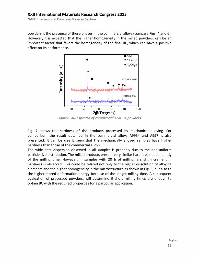
Fig. 6 shows the XRD spectra of commercial powders (AMDRY 9954 and 997). Sharp and high-intensity peaks are observed, without any reflections of pure elements. For the A9954, three phases identified as CrNi, AlCo2Cr and Al9Co2Ni were detected, according to the JCPDS diffraction cards 01-071-7594, 00-071-5665 and 00-052-0802, respectively. The peaks with the highest intensity correspond to CrNi and those with the lowest, to Al9Co2Ni. The XRD spectrum of the A977 shows only the presence of CrNi and AlCo2Cr phases. The high-intensity peaks correspond to the CrNi phase and the Al9Co2Ni was not detected. The main difference in the XRD spectra of commercial and manufactured
XXII International Materials Research Congress 2013 NACE International Congress-Mexican Section
11
Página
powders is the presence of these phases in the commercial alloys (compare Figs. 4 and 6). However, it is expected that the higher homogeneity in the milled powders, can be an important factor that favors the homogeneity of the final BC, which can have a positive effect on its performance.
20 40 60 80 100 120
AMDRY 997
AMDRY 9954
CrNi
AlCo2Cr
Al9Co
2Ni
2 (Degrees)
Inte
nsi
ty (
a.
u.)
Figure6. XRD spectra of commercial AMDRY powders.
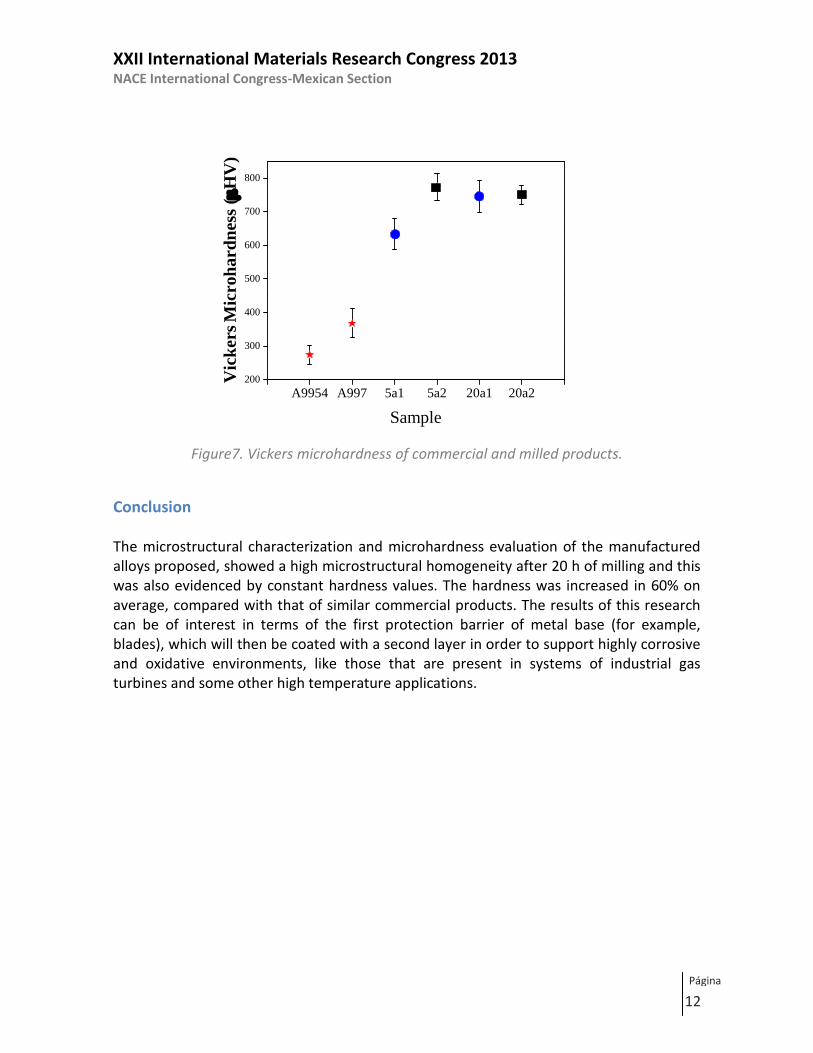
Fig. 7 shows the hardness of the products processed by mechanical alloying. For comparison, the result obtained in the commercial alloys A9954 and A997 is also presented. It can be clearly seen that the mechanically alloyed samples have higher hardness than those of the commercial alloys. The wide data dispersion observed in all samples is probably due to the non-uniform particle size distribution. The milled products present very similar hardness independently of the milling time. However, in samples with 20 h of milling, a slight increment in hardness is observed. This could be related not only to the higher dissolution of alloying elements and the higher homogeneity in the microstructure as shown in Fig. 3, but also to the higher stored deformation energy because of the longer milling time. A subsequent evaluation of processed powders, will determine if short milling times are enough to obtain BC with the required properties for a particular application.
XXII International Materials Research Congress 2013 NACE International Congress-Mexican Section
12
Página
A9954 A997 5a1 5a2 20a1 20a2200
300
400
500
600
700
800
Vic
ker
s M
icro
ha
rdn
ess
(H
V)
Sample
Figure7. Vickers microhardness of commercial and milled products.
Conclusion The microstructural characterization and microhardness evaluation of the manufactured alloys proposed, showed a high microstructural homogeneity after 20 h of milling and this was also evidenced by constant hardness values. The hardness was increased in 60% on average, compared with that of similar commercial products. The results of this research can be of interest in terms of the first protection barrier of metal base (for example, blades), which will then be coated with a second layer in order to support highly corrosive and oxidative environments, like those that are present in systems of industrial gas turbines and some other high temperature applications.
XXII International Materials Research Congress 2013 NACE International Congress-Mexican Section
13
Página
References
[1]. X. Q. Cao, R. Vassen and D. Stoever, Journal of the European Ceramic Society 24 (2004) 1-10.
[2]. C. G. Levi, Current Opinion in Solid State and Materials Science 8 (2004) 77-91. [3]. U. Schulz, B. Saruhan, K. Fritscher and C. Leyens, International Journal of Applied
Ceramic Technology 1 (2004) 302-315. [4]. Z. A. Chaudhury et al., Journal of Materials Science 34 (1999) 2475-2481. [5]. B. Tryon, F. Cao, K. S. Murphy, C. G. Levi and T. M. Pollock, Journal of the Minerals,
Metals and Materials Society 58 (2006) 53-59. [6]. A. G. Evans and J. W. Hutchinson, Surface and Coatings Technology 201 (2007)
7905-7916. [7]. A. G. Evans, D. R. Clarke and C. G. Levi, Journal of the European Ceramic Society 28
(2008) 1405-1419. [8]. R. C. Reed, The Superalloys: Fundamentals and Applications, Cambridge University
Press, Cambridge 2006. [9]. S. Bose, High Temperature Coatings, Butterworth-Heinemann, 2007. [10]. J. R. Nicholls, MRS Bulletin 28 (2003) 659-670. [11]. R. Vaßen, F. Traeger and D. Stöver, International Journal of Applied Ceramic
Technology 1 (2004) 351-361. [12]. A. G. Evans et al., Progress in Materials Science 46 (2001) 505-553. [13]. C. Suryanarayana, Progress in Materials Science 46 (2001) 1-184. [14]. S. Ram, Materials Science and Engineering A 304-306 (2001) 923-927. [15]. J. Y. Huang, Y. K. Wu and H. Q. Ye, Acta Materialia 44 (1996) 1201-1209.