Embed Size (px)
Citation preview
REV_4: 2015-08-24
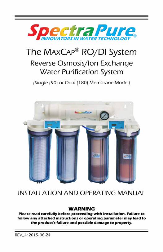
The MAXCAP® RO/DI SystemReverse Osmosis/Ion Exchange
Water Purification System(Single (90) or Dual (180) Membrane Model)
INSTALLATION AND OPERATING MANUAL
WARNINGPlease read carefully before proceeding with installation. Failure to
follow any attached instructions or operating parameter may lead to the product’s failure and possible damage to property.
SpectraPure ®
SpectraPure®Inc. 480.894.5437 Call us toll-free 1.800.685.2783 2167 East Fifth St, Tempe, Arizona 852812
TABLE OF CONTENTS:Thank You for your purchase of a SpectraPure® System. With proper installation and maintenance, this system will provide you with high quality water for years to come. All SpectraPure® products are rigorously tested by us for safety and reliability. If you have any questions or concerns, please contact our customer service department at 1.800.685.2783 or refer to our online troubleshooting at www.spectrapure.com.
Table of Contents ............................................................................................................... 2System Information
System Specifications ............................................................................................... 3System Description ................................................................................................... 4
InstallationSystem Installation and Initialization .............................................................. 4 -5System Components ................................................................................................ 6Measuring Waste to Product Water Ratio ........................................................ 7Flow Restrictor Removal, Adjustment and Replacement ........................ 8 -9Flow Restrictor Tables ........................................................................................... 10
Using your Systems Basic PartsMetering & Diagnostics ....................................................................................... 11
Filter DiagnosticsSediment Filter Diagnostic .................................................................................. 12Carbon Filter Diagnostic ...................................................................................... 13RO Membrane Diagnostic ............................................................................ 14 -18Deionization Cartridge Diagnostic ................................................................... 19
Troubleshooting GuideTroubleshooting Guide ........................................................................................ 20Maintenance ........................................................................................................... 21Storage and Mounting ......................................................................................... 22
Warranty .............................................................................................................................. 23Replacement & Optional Parts ................................................................................... 24
Warning: SpectraPure does not recommend drinking deionized water.
COPYRIGHT 2002-2015© BY SPECTRAPURE INCALL RIGHTS RESERVED
No part of this publication may be reproduced, stored in a retrieval system, or transmitted in any form or by any means, electronic, mechanical, photocopying, recording or otherwise without the prior written permission of SpectraPure Inc.
SpectraPure®Inc. Fax 480.894.6109 Fax us toll-free 1.877.527.7873E-mail: [email protected] Visit us on the web www.spectrapure.com 3
SpectraPure ®
SYSTEM SPECIFICATIONS:Sediment Prefilter 0.5 micron MicroTec™ sediment prefilter (SF-MT-0.5-10)Carbon Filter 0.5 micron carbon block prefilter (CF-0.5-10)RO Membrane Type Thin-Film Composite (TFC)DI Cartridges MaxCap® DI
SilicaBuster™ DIRejection Rate 98% averageInput Water Pressure 60 psi (4.15 bar) line pressure*Input Water Temp 77°F (25°C)Recovery Rate 20% (i.e. 20% of the water will be collected as pure water)
Nominal Membrane Flow Rates @ 60 psi, 77° F:
GPD (lpd) Product Water Flow Rate Concentrate Flow Rate90 (340) 235ml/min 940 ml/min
180 (680) 470 ml/min 1880 ml/min
Higher TDS, harder tap water, higher temperature, greater recovery rate, or lower operating pressure may contribute to reduced permeate flow and/or lower TDS rejection.
Reverse Osmosis Membrane Feed Water Requirements:
Operating Pressure* 40–80 psi (2.75–5.5 bar)pH Range 3 –10Maximum Temperature 113° F (45° C)Maximum Turbidity 1.0 NTUMaximum Silt Density Index 5.0 (based on 15 min. test time)Maximum Chlorine less than 0.1 ppmMaximum TDS 1500 ppmMaximum Hardness 10 grains (170 ppm as CaCO3)Maximum Iron less than 0.1 ppmMaximum Manganese less than 0.1 ppmMaximum Hydrogen Sulfide 0 ppmLangelier Saturation Index LSI must be negative
*Operating pressure less than 40 psi may require a booster pump:
Use BPLF-MO-115(-230) for Manual Operation, or BPHF-PS-250/4-115 with Electronic Solenoid and Pressure Switch Control
*Operating pressure greater than 80 psi may require a pressure reducing valve.
SpectraPure ®
SpectraPure®Inc. 480.894.5437 Call us toll-free 1.800.685.2783 2167 East Fifth St, Tempe, Arizona 852814
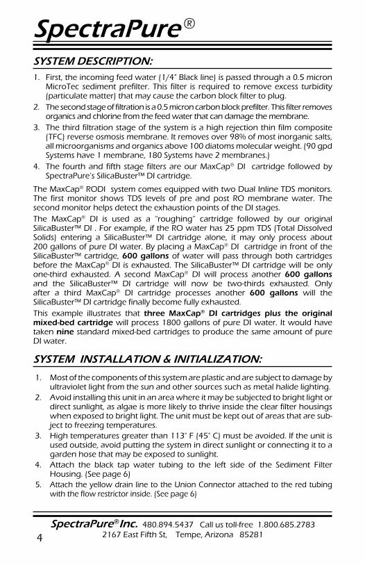
SYSTEM DESCRIPTION: 1. First, the incoming feed water (1/4" Black line) is passed through a 0.5 micron
MicroTec sediment prefilter. This filter is required to remove excess turbidity (particulate matter) that may cause the carbon block filter to plug.
2. The second stage of filtration is a 0.5 micron carbon block prefilter. This filter removes organics and chlorine from the feed water that can damage the membrane.
3. The third filtration stage of the system is a high rejection thin film composite (TFC) reverse osmosis membrane. It removes over 98% of most inorganic salts, all microorganisms and organics above 100 diatoms molecular weight. (90 gpd Systems have 1 membrane, 180 Systems have 2 membranes.)
4. The fourth and fifth stage filters are our MaxCap® DI cartridge followed by SpectraPure’s SilicaBuster™ DI cartridge.
The MaxCap® RODI system comes equipped with two Dual Inline TDS monitors. The first monitor shows TDS levels of pre and post RO membrane water. The second monitor helps detect the exhaustion points of the DI stages.The MaxCap® DI is used as a “roughing” cartridge followed by our original SilicaBuster™ DI . For example, if the RO water has 25 ppm TDS (Total Dissolved Solids) entering a SilicaBuster™ DI cartridge alone, it may only process about 200 gallons of pure DI water. By placing a MaxCap® DI cartridge in front of the SilicaBuster™ cartridge, 600 gallons of water will pass through both cartridges before the MaxCap® DI is exhausted. The SilicaBuster™ DI cartridge will be only one-third exhausted. A second MaxCap® DI will process another 600 gallons and the SilicaBuster™ DI cartridge will now be two-thirds exhausted. Only after a third MaxCap® DI cartridge processes another 600 gallons will the SilicaBuster™ DI cartridge finally become fully exhausted.This example illustrates that three MaxCap® DI cartridges plus the original mixed-bed cartridge will process 1800 gallons of pure DI water. It would have taken nine standard mixed-bed cartridges to produce the same amount of pure DI water.
SYSTEM INSTALLATION & INITIALIZATION:
1. Most of the components of this system are plastic and are subject to damage by ultraviolet light from the sun and other sources such as metal halide lighting.
2. Avoid installing this unit in an area where it may be subjected to bright light or direct sunlight, as algae is more likely to thrive inside the clear filter housings when exposed to bright light. The unit must be kept out of areas that are sub-ject to freezing temperatures.
3. High temperatures greater than 113° F (45° C) must be avoided. If the unit is used outside, avoid putting the system in direct sunlight or connecting it to a garden hose that may be exposed to sunlight.
4. Attach the black tap water tubing to the left side of the Sediment Filter Housing. (See page 6)
5. Attach the yellow drain line to the Union Connector attached to the red tubing with the flow restrictor inside. (See page 6)
SpectraPure®Inc. Fax 480.894.6109 Fax us toll-free 1.877.527.7873E-mail: [email protected] Visit us on the web www.spectrapure.com 5
SpectraPure ®
SYSTEM INSTALLATION & INITIALIZATION: (continued)
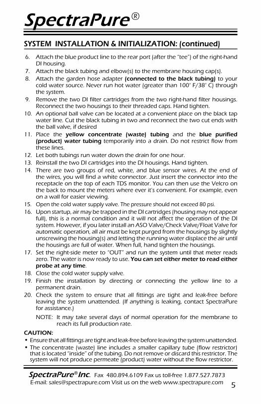
6. Attach the blue product line to the rear port (after the “tee”) of the right-hand DI housing.
7. Attach the black tubing and elbow(s) to the membrane housing cap(s).8. Attach the garden hose adapter (connected to the black tubing) to your
cold water source. Never run hot water (greater than 100° F/38° C) through the system.
9. Remove the two DI filter cartridges from the two right-hand filter housings. Reconnect the two housings to their threaded caps. Hand tighten.
10. An optional ball valve can be located at a convenient place on the black tap water line. Cut the black tubing in two and reconnect the two cut ends with the ball valve, if desired
11. Place the yellow concentrate (waste) tubing and the blue purified (product) water tubing temporarily into a drain. Do not restrict flow from these lines.
12. Let both tubings run water down the drain for one hour.13. Reinstall the two DI cartridges into the DI housings. Hand tighten.14. There are two groups of red, white, and blue sensor wires. At the end of
the wires, you will find a white connector. Just insert the connector into the receptacle on the top of each TDS monitor. You can then use the Velcro on the back to mount the meters where ever it’s convenient. For example, even on a wall for easier viewing.
15. Open the cold water supply valve. The pressure should not exceed 80 psi. 16. Upon startup, air may be trapped in the DI cartridges (housing may not appear
full), this is a normal condition and it will not affect the operation of the DI system. However, if you later install an ASO Valve/Check Valve/Float Valve for automatic operation, all air must be kept purged from the housings by slightly unscrewing the housing(s) and letting the running water displace the air until the housings are full of water. When full, hand tighten the housings.
17. Set the right-side meter to “OUT” and run the system until that meter reads zero. The water is now ready to use. You can set either meter to read either probe at any time.
18. Close the cold water supply valve.19. Finish the installation by directing or connecting the yellow line to a
permanent drain. 20. Check the system to ensure that all fittings are tight and leak-free before
leaving the system unattended. (If anything is leaking, contact SpectraPure for assistance.)
NOTE: It may take several days of normal operation for the membrane to reach its full production rate.
CAUTION: • Ensure that all fittings are tight and leak-free before leaving the system unattended.• The concentrate (waste) line includes a smaller capillary tube (flow restrictor)
that is located “inside” of the tubing. Do not remove or discard this restrictor. The system will not produce permeate (product) water without the flow restrictor.
SpectraPure ®
SpectraPure®Inc. 480.894.5437 Call us toll-free 1.800.685.2783 2167 East Fifth St, Tempe, Arizona 852816
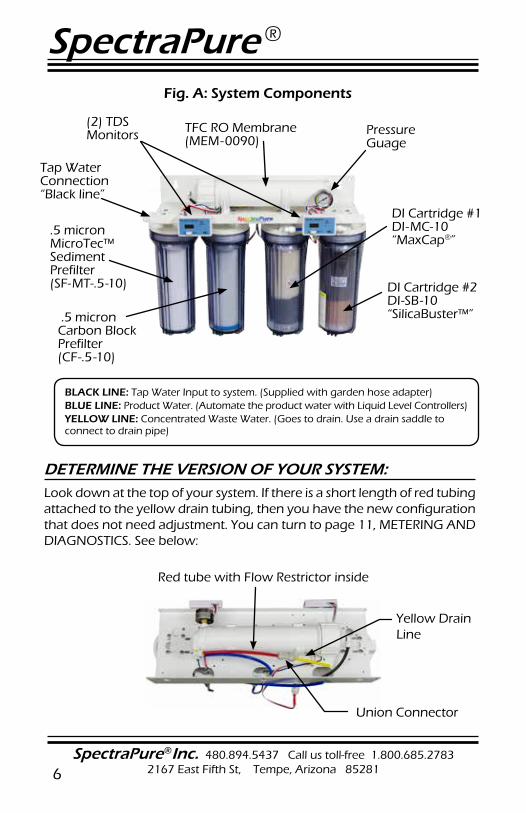
Fig. A: System Components
TFC RO Membrane(MEM-0090)
.5 micron MicroTec™Sediment Prefilter(SF-MT-.5-10)
.5 micron Carbon Block Prefilter (CF-.5-10)
Pressure Guage
(2) TDS Monitors
DI Cartridge #1 DI-MC-10“MaxCap®”
DI Cartridge #2 DI-SB-10“SilicaBuster™”
Tap Water Connection“Black line”
BLACK LINE: Tap Water Input to system. (Supplied with garden hose adapter) BLUE LINE: Product Water. (Automate the product water with Liquid Level Controllers) YELLOW LINE: Concentrated Waste Water. (Goes to drain. Use a drain saddle to connect to drain pipe)
DETERMINE THE VERSION OF YOUR SYSTEM: Look down at the top of your system. If there is a short length of red tubing attached to the yellow drain tubing, then you have the new configuration that does not need adjustment. You can turn to page 11, METERING AND DIAGNOSTICS. See below:
Red tube with Flow Restrictor inside
Union Connector
Yellow Drain Line
SpectraPure®Inc. Fax 480.894.6109 Fax us toll-free 1.877.527.7873E-mail: [email protected] Visit us on the web www.spectrapure.com 7
SpectraPure ®
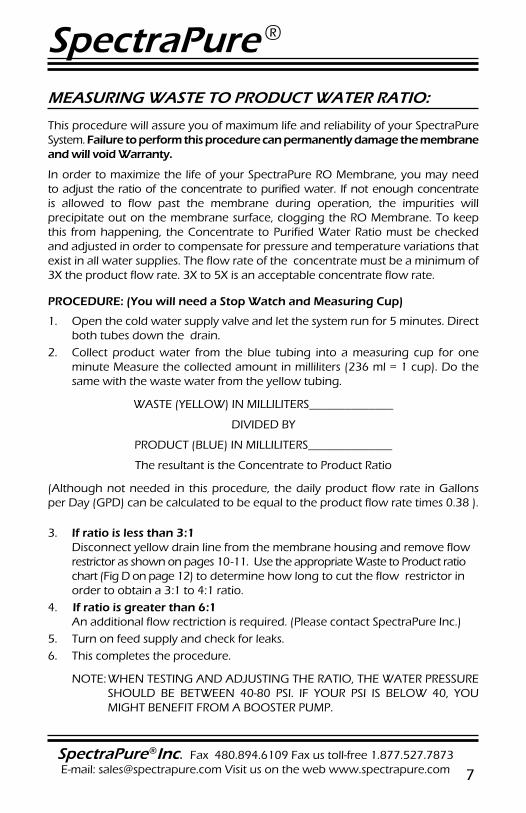
MEASURING WASTE TO PRODUCT WATER RATIO:
This procedure will assure you of maximum life and reliability of your SpectraPure System. Failure to perform this procedure can permanently damage the membrane and will void Warranty.
In order to maximize the life of your SpectraPure RO Membrane, you may need to adjust the ratio of the concentrate to purified water. If not enough concentrate is allowed to flow past the membrane during operation, the impurities will precipitate out on the membrane surface, clogging the RO Membrane. To keep this from happening, the Concentrate to Purified Water Ratio must be checked and adjusted in order to compensate for pressure and temperature variations that exist in all water supplies. The flow rate of the concentrate must be a minimum of 3X the product flow rate. 3X to 5X is an acceptable concentrate flow rate.
PROCEDURE: (You will need a Stop Watch and Measuring Cup)
1. Open the cold water supply valve and let the system run for 5 minutes. Direct both tubes down the drain.
2. Collect product water from the blue tubing into a measuring cup for one minute Measure the collected amount in milliliters (236 ml = 1 cup). Do the same with the waste water from the yellow tubing.
WASTE (YELLOW) IN MILLILITERS______________
DIVIDED BY
PRODUCT (BLUE) IN MILLILITERS______________
The resultant is the Concentrate to Product Ratio
(Although not needed in this procedure, the daily product flow rate in Gallons per Day (GPD) can be calculated to be equal to the product flow rate times 0.38 ).
3. If ratio is less than 3:1 Disconnect yellow drain line from the membrane housing and remove flow restrictor as shown on pages 10-11. Use the appropriate Waste to Product ratio chart (Fig D on page 12) to determine how long to cut the flow restrictor in order to obtain a 3:1 to 4:1 ratio.
4. If ratio is greater than 6:1 An additional flow rectriction is required. (Please contact SpectraPure Inc.)
5. Turn on feed supply and check for leaks.6. This completes the procedure.
NOTE: WHEN TESTING AND ADJUSTING THE RATIO, THE WATER PRESSURE SHOULD BE BETWEEN 40-80 PSI. IF YOUR PSI IS BELOW 40, YOU MIGHT BENEFIT FROM A BOOSTER PUMP.
SpectraPure ®
SpectraPure®Inc. 480.894.5437 Call us toll-free 1.800.685.2783 2167 East Fifth St, Tempe, Arizona 852818
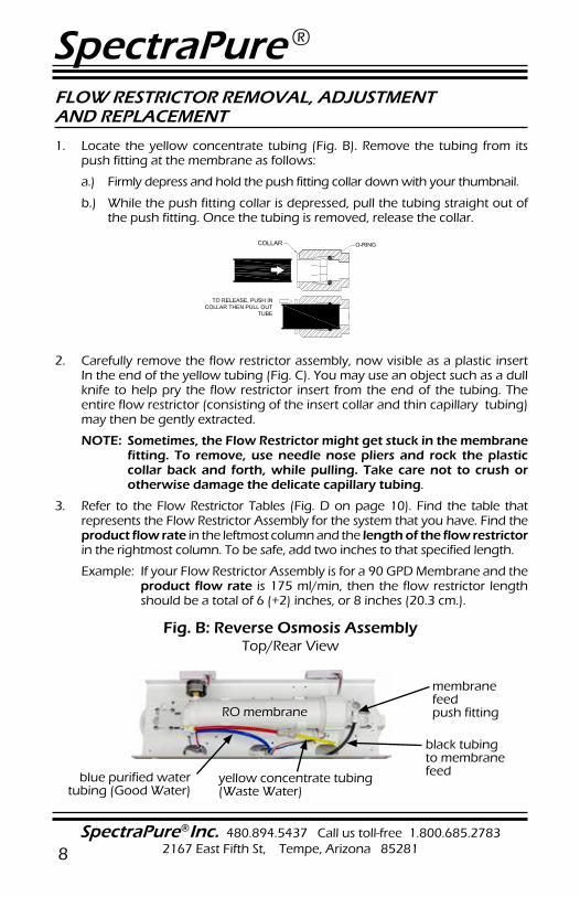
Fig. B: Reverse Osmosis Assembly Top/Rear View
membrane feed push fitting
black tubing to membrane feed
RO membrane
yellow concentrate tubing(Waste Water)
blue purified water tubing (Good Water)
FLOW RESTRICTOR REMOVAL, ADJUSTMENT AND REPLACEMENT
1. Locate the yellow concentrate tubing (Fig. B). Remove the tubing from its push fitting at the membrane as follows:
a.) Firmly depress and hold the push fitting collar down with your thumbnail.
b.) While the push fitting collar is depressed, pull the tubing straight out of the push fitting. Once the tubing is removed, release the collar.
2. Carefully remove the flow restrictor assembly, now visible as a plastic insert In the end of the yellow tubing (Fig. C). You may use an object such as a dull knife to help pry the flow restrictor insert from the end of the tubing. The entire flow restrictor (consisting of the insert collar and thin capillary tubing) may then be gently extracted.
NOTE: Sometimes, the Flow Restrictor might get stuck in the membrane fitting. To remove, use needle nose pliers and rock the plastic collar back and forth, while pulling. Take care not to crush or otherwise damage the delicate capillary tubing.
3. Refer to the Flow Restrictor Tables (Fig. D on page 10). Find the table that represents the Flow Restrictor Assembly for the system that you have. Find the product flow rate in the leftmost column and the length of the flow restrictor in the rightmost column. To be safe, add two inches to that specified length.
Example: If your Flow Restrictor Assembly is for a 90 GPD Membrane and the product flow rate is 175 ml/min, then the flow restrictor length should be a total of 6 (+2) inches, or 8 inches (20.3 cm.).
SpectraPure®Inc. Fax 480.894.6109 Fax us toll-free 1.877.527.7873E-mail: [email protected] Visit us on the web www.spectrapure.com 9
SpectraPure ®
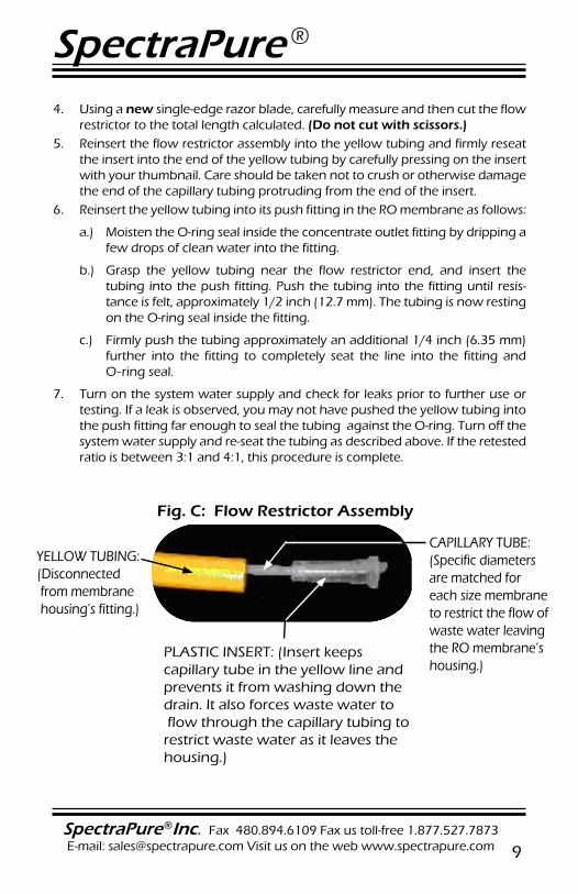
4. Using a new single-edge razor blade, carefully measure and then cut the flow restrictor to the total length calculated. (Do not cut with scissors.)
5. Reinsert the flow restrictor assembly into the yellow tubing and firmly reseat the insert into the end of the yellow tubing by carefully pressing on the insert with your thumbnail. Care should be taken not to crush or otherwise damage the end of the capillary tubing protruding from the end of the insert.
6. Reinsert the yellow tubing into its push fitting in the RO membrane as follows:
a.) Moisten the O-ring seal inside the concentrate outlet fitting by dripping a few drops of clean water into the fitting.
b.) Grasp the yellow tubing near the flow restrictor end, and insert the tubing into the push fitting. Push the tubing into the fitting until resis-tance is felt, approximately 1/2 inch (12.7 mm). The tubing is now resting on the O-ring seal inside the fitting.
c.) Firmly push the tubing approximately an additional 1/4 inch (6.35 mm) further into the fitting to completely seat the line into the fitting and O-ring seal.
7. Turn on the system water supply and check for leaks prior to further use or testing. If a leak is observed, you may not have pushed the yellow tubing into the push fitting far enough to seal the tubing against the O-ring. Turn off the system water supply and re-seat the tubing as described above. If the retested ratio is between 3:1 and 4:1, this procedure is complete.
YELLOW TUBING: (Disconnected from membrane housing’s fitting.)
CAPILLARY TUBE: (Specific diameters are matched for each size membrane to restrict the flow of waste water leaving the RO membrane’s housing.)
PLASTIC INSERT: (Insert keeps capillary tube in the yellow line and prevents it from washing down the drain. It also forces waste water to flow through the capillary tubing to restrict waste water as it leaves the housing.)
Fig. C: Flow Restrictor Assembly
SpectraPure ®
SpectraPure®Inc. 480.894.5437 Call us toll-free 1.800.685.2783 2167 East Fifth St, Tempe, Arizona 8528110
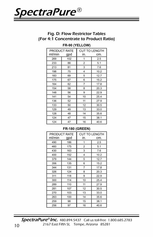
Fig. D: Flow Restrictor Tables(For 4:1 Concentrate to Product Ratio)
FR-90 (YELLOW)PRODUCT RATE CUT TO LENGTHml/min gpd in. cm.
269 102 1 2.5233 88 2 5.1213 81 3 7.6198 75 4 10.2183 69 5 12.7175 67 6 15.2164 62 7 17.8154 58 8 20.3148 56 9 22.9141 54 10 25.4136 52 11 27.9133 50 12 30.5129 49 13 33.0128 48 14 35.6124 47 15 38.1124 47 16 40.6
FR-180 (GREEN)PRODUCT RATE CUT TO LENGTHml/min gpd in. cm.
490 186 1 2.5460 175 2 5.1430 163 3 7.6400 152 4 10.2379 144 5 12.7356 135 6 15.2344 131 7 17.8326 124 8 20.3311 118 9 22.9300 114 10 25.4289 110 11 27.9281 107 12 30.5270 103 13 33.0263 100 14 35.6259 98 15 38.1256 97 16 40.6
SpectraPure®Inc. Fax 480.894.6109 Fax us toll-free 1.877.527.7873E-mail: [email protected] Visit us on the web www.spectrapure.com 11
SpectraPure ®
METERING AND DIAGNOSTICS:
This SpectraPure purification system has been fully equipped with sufficient instrumentation to make monitoring and troubleshooting an easy process. The provided pressure gauge is used to determine the tap water pressure and to evaluate the condition of the sediment and carbon prefilters. The pressure will drop as the prefilters become clogged by dirt [turbidity] from the tap water.
The digital TDS meter (left side) will provide a reliable means of evaluating the efficiency of the RO membrane. This meter will indicate the tap water conductivity (“IN”) and the RO water conductivity (“OUT”).
The difference between the two meter readings will be used to calculate the percentage of rejection of the (TFC) RO membrane.
The Digital TDS meter (right side) will be used to determine the condition of the two stages of the DI system. As the reading on the meter begin to rise above zero, the operator will be alerted to the possibility that the DI system may have deteriorated past the exhaustion point and that the DI cartridge(s) may need to be replaced.
Warning!!: The DM1 TDS Meter does not detect the presence of CO2, silica, organic contaminants or microorganisms, nor should it be used as a medical or scientific instrument. It should be used as an indicator or guide only, and does not imply water safe for human consumption. No application other than monitoring the electrical conductivity of water is expressed or implied.
USING THE PRESSURE GAUGE
The pressure gauge is used to monitor the condition of the Sediment and CarbonPrefilters. With the Sediment and Carbon filters removed, the gauge will indicate the “actual” tap water input pressure. When the prefilters are “new”, the pressure shown on the gauge will be slightly less than the actual tap water pressure and as the filters age, the pressure will drop due to the dirt that will collect in the prefilters. When the pressure on the gauge drops below 40-PSI or as the filters collect particulates and the pressure drop is greater than 15% to 20% of the normal water pressure, the prefilters are in need of replacement.
NOTE: When the pressure on the pressure gauge drops below the normal readings; do not assume that the sediment filter is the only cause. In some geographical areas where the input water contains a high percentage of very small micron particulates, the carbon filter may become clogged before the sediment filter. (The filters may look new but still cause the water pressure to drop). Do not judge the condition of the prefilters by their color, always use the pressure gauge to determine the condition of the prefilters.
SpectraPure ®
SpectraPure®Inc. 480.894.5437 Call us toll-free 1.800.685.2783 2167 East Fifth St, Tempe, Arizona 8528112
SEDIMENT PREFILTER REPLACEMENT:
A Sediment Filter will usually last approx. 4-6 months, depending on the quality of the tap water and quantity of water being produced. (The life span of the filter is determined by the turbidity, iron content, organics, and total particulate volume in your water source). The best way to determine when your Sediment Prefilter needs replacement is to monitor the Pressure Gauge. When you have a drop in pressure of15-20% below your normal gauge pressure, replace the filter. To verify this, run water through the system without the filter in its housing. If the pressure returns to your normal house pressure without the filter, you will know the filter you just took out was plugged up and causing the pressure drop.
**NOTE: A drop in the system’s production is, in most cases, an indication that the sediment filter has become saturated with contaminants and will need to be replaced. If you remove the sediment and the pressure does not return to normal, the carbon filter may be plugged. If your water contains a great deal of sediment or chlorine, the prefilters may require more frequent changes to maintain ade-quate production rate and extended membrane life.
Sediment Prefilter Replacement Procedure
Materials Required: 0.5 micron MicroTec™ Sediment Filter (SF-MT-0.5 -10), Filter Wrench
1. Turn off water supply to the system.
2. Refer to Fig. A (System Picture). Using the provided filter housing wrench, remove the first housing on the left. Unscrew it counterclockwise as viewed from the bottom.
3. Remove the old filter and discard.
4. Thoroughly wash the housing with a mixture of hot soapy water and a few teaspoons of household bleach. Rinse well with clean hot water.
5. Insert the new prefilter into the housing. Screw the housing back onto the assembly and hand-tighten only.
NOTE: Do not use filter wrench to tighten housings. Over-tightening will damage housings and void your warranty.
6. Proceed with carbon block filter replacement, if needed.
NOTE: If your water contains a great deal of sediment or chlorine, the prefilters may require more frequent changes to maintain adequate production rate and extended membrane life.
SpectraPure®Inc. Fax 480.894.6109 Fax us toll-free 1.877.527.7873E-mail: [email protected] Visit us on the web www.spectrapure.com 13
SpectraPure ®
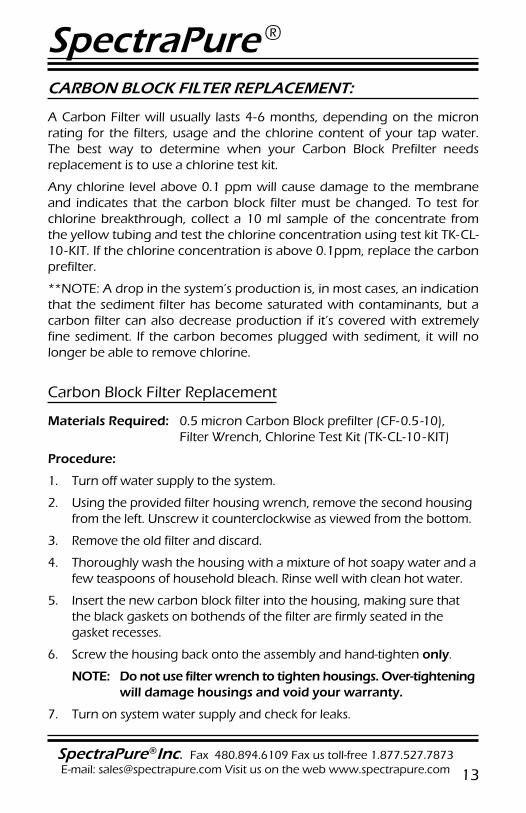
CARBON BLOCK FILTER REPLACEMENT:
A Carbon Filter will usually lasts 4-6 months, depending on the micron rating for the filters, usage and the chlorine content of your tap water. The best way to determine when your Carbon Block Prefilter needs replacement is to use a chlorine test kit.
Any chlorine level above 0.1 ppm will cause damage to the membrane and indicates that the carbon block filter must be changed. To test for chlorine breakthrough, collect a 10 ml sample of the concentrate from the yellow tubing and test the chlorine concentration using test kit TK-CL-10-KIT. If the chlorine concentration is above 0.1ppm, replace the carbon prefilter.
**NOTE: A drop in the system’s production is, in most cases, an indication that the sediment filter has become saturated with contaminants, but a carbon filter can also decrease production if it’s covered with extremely fine sediment. If the carbon becomes plugged with sediment, it will no longer be able to remove chlorine.
Carbon Block Filter Replacement
Materials Required: 0.5 micron Carbon Block prefilter (CF-0.5 -10), Filter Wrench, Chlorine Test Kit (TK-CL-10 -KIT)
Procedure:
1. Turn off water supply to the system.
2. Using the provided filter housing wrench, remove the second housing from the left. Unscrew it counterclockwise as viewed from the bottom.
3. Remove the old filter and discard.
4. Thoroughly wash the housing with a mixture of hot soapy water and a few teaspoons of household bleach. Rinse well with clean hot water.
5. Insert the new carbon block filter into the housing, making sure that the black gaskets on bothends of the filter are firmly seated in the gasket recesses.
6. Screw the housing back onto the assembly and hand-tighten only.
NOTE: Do not use filter wrench to tighten housings. Over-tightening will damage housings and void your warranty.
7. Turn on system water supply and check for leaks.
SpectraPure ®
SpectraPure®Inc. 480.894.5437 Call us toll-free 1.800.685.2783 2167 East Fifth St, Tempe, Arizona 8528114
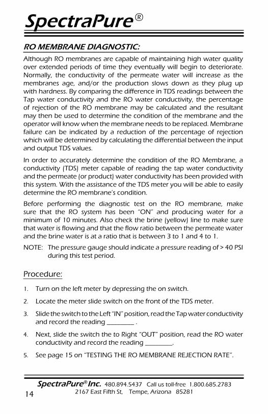
RO MEMBRANE DIAGNOSTIC: Although RO membranes are capable of maintaining high water quality over extended periods of time they eventually will begin to deteriorate. Normally, the conductivity of the permeate water will increase as the membranes age, and/or the production slows down as they plug up with hardness. By comparing the difference in TDS readings between the Tap water conductivity and the RO water conductivity, the percentage of rejection of the RO membrane may be calculated and the resultant may then be used to determine the condition of the membrane and the operator will know when the membrane needs to be replaced. Membrane failure can be indicated by a reduction of the percentage of rejection which will be determined by calculating the differential between the input and output TDS values.
In order to accurately determine the condition of the RO Membrane, a conductivity (TDS) meter capable of reading the tap water conductivity and the permeate (or product) water conductivity has been provided with this system. With the assistance of the TDS meter you will be able to easily determine the RO membrane’s condition.
Before performing the diagnostic test on the RO membrane, make sure that the RO system has been “ON” and producing water for a minimum of 10 minutes. Also check the brine (yellow) line to make sure that water is flowing and that the flow ratio between the permeate water and the brine water is at a ratio that is between 3 to 1 and 4 to 1.
NOTE: The pressure gauge should indicate a pressure reading of > 40 PSI during this test period.
Procedure:
1. Turn on the left meter by depressing the on switch.
2. Locate the meter slide switch on the front of the TDS meter.
3. Slide the switch to the Left “IN” position, read the Tap water conductivity and record the reading ________ .
4. Next, slide the switch the to Right “OUT” position, read the RO water conductivity and record the reading ________.
5. See page 15 on “TESTING THE RO MEMBRANE REJECTION RATE”.
SpectraPure®Inc. Fax 480.894.6109 Fax us toll-free 1.877.527.7873E-mail: [email protected] Visit us on the web www.spectrapure.com 15
SpectraPure ®
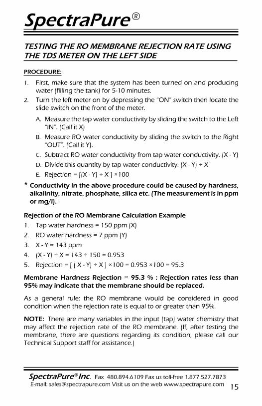
TESTING THE RO MEMBRANE REJECTION RATE USING THE TDS METER ON THE LEFT SIDE
PROCEDURE:
1. First, make sure that the system has been turned on and producing water (filling the tank) for 5-10 minutes.
2. Turn the left meter on by depressing the “ON” switch then locate the slide switch on the front of the meter.
A. Measure the tap water conductivity by sliding the switch to the Left “IN”. (Call it X)
B. Measure RO water conductivity by sliding the switch to the Right “OUT”. (Call it Y).
C. Subtract RO water conductivity from tap water conductivity. (X - Y)
D. Divide this quantity by tap water conductivity. (X - Y) ÷ X
E. Rejection = [(X - Y) ÷ X ] ×100
* Conductivity in the above procedure could be caused by hardness, alkalinity, nitrate, phosphate, silica etc. (The measurement is in ppm or mg/l).
Rejection of the RO Membrane Calculation Example
1. Tap water hardness = 150 ppm (X)
2. RO water hardness = 7 ppm (Y)
3. X - Y = 143 ppm
4. (X - Y) ÷ X = 143 ÷ 150 = 0.953
5. Rejection = [ ( X - Y) ÷ X ] ×100 = 0.953 ×100 = 95.3
Membrane Hardness Rejection = 95.3 % : Rejection rates less than 95% may indicate that the membrane should be replaced.
As a general rule; the RO membrane would be considered in good condition when the rejection rate is equal to or greater than 95%.
NOTE: There are many variables in the input (tap) water chemistry that may affect the rejection rate of the RO membrane. (If, after testing the membrane, there are questions regarding its condition, please call our Technical Support staff for assistance.)
SpectraPure ®
SpectraPure®Inc. 480.894.5437 Call us toll-free 1.800.685.2783 2167 East Fifth St, Tempe, Arizona 8528116
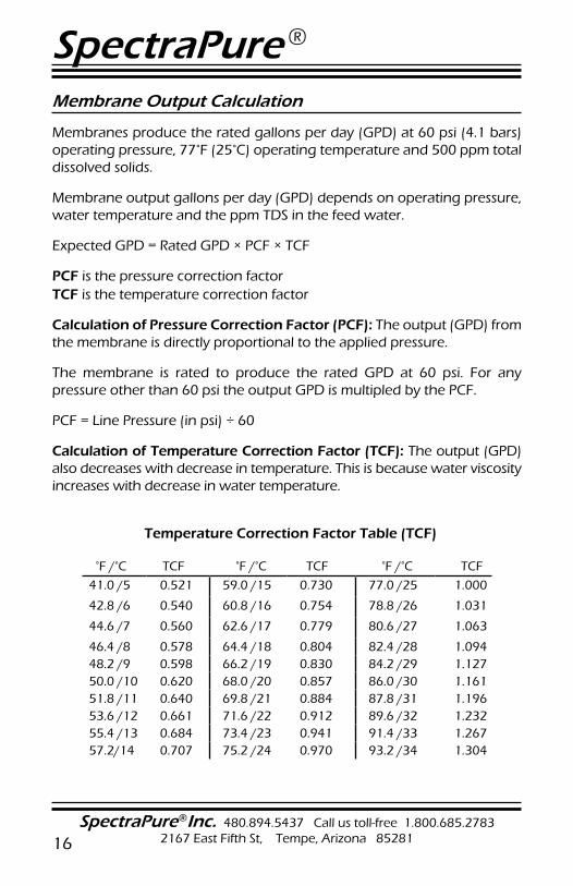
Membrane Output Calculation
Membranes produce the rated gallons per day (GPD) at 60 psi (4.1 bars) operating pressure, 77°F (25°C) operating temperature and 500 ppm total dissolved solids.
Membrane output gallons per day (GPD) depends on operating pressure, water temperature and the ppm TDS in the feed water.
Expected GPD = Rated GPD × PCF × TCF
PCF is the pressure correction factorTCF is the temperature correction factor
Calculation of Pressure Correction Factor (PCF): The output (GPD) from the membrane is directly proportional to the applied pressure.
The membrane is rated to produce the rated GPD at 60 psi. For any pressure other than 60 psi the output GPD is multipled by the PCF.
PCF = Line Pressure (in psi) ÷ 60
Calculation of Temperature Correction Factor (TCF): The output (GPD) also decreases with decrease in temperature. This is because water viscosity increases with decrease in water temperature.
Temperature Correction Factor Table (TCF)
°F /°C TCF °F /°C TCF °F /°C TCF
41.0 /5 0.521 59.0 /15 0.730 77.0 /25 1.000
42.8 /6 0.540 60.8 /16 0.754 78.8 /26 1.031
44.6 /7 0.560 62.6 /17 0.779 80.6 /27 1.063
46.4 /8 0.578 64.4 /18 0.804 82.4 /28 1.09448.2 /9 0.598 66.2 /19 0.830 84.2 /29 1.12750.0 /10 0.620 68.0 /20 0.857 86.0 /30 1.16151.8 /11 0.640 69.8 /21 0.884 87.8 /31 1.19653.6 /12 0.661 71.6 /22 0.912 89.6 /32 1.23255.4 /13 0.684 73.4 /23 0.941 91.4 /33 1.26757.2/14 0.707 75.2 /24 0.970 93.2 /34 1.304
SpectraPure®Inc. Fax 480.894.6109 Fax us toll-free 1.877.527.7873E-mail: [email protected] Visit us on the web www.spectrapure.com 17
SpectraPure ®
RO MEMBRANE REPLACEMENT:
1. Turn off the water supply to the RO system. Place the system where the membrane housing is easily accessible.
2. Remove the black tubing from the membrane feed push fitting by depressing the collar on the fitting with your thumb and pulling the tubing from the push fitting (Page 10).
3. Lift the membrane housing from the retention clips.
4. Unscrew the membrane housing lid. This may require two people.
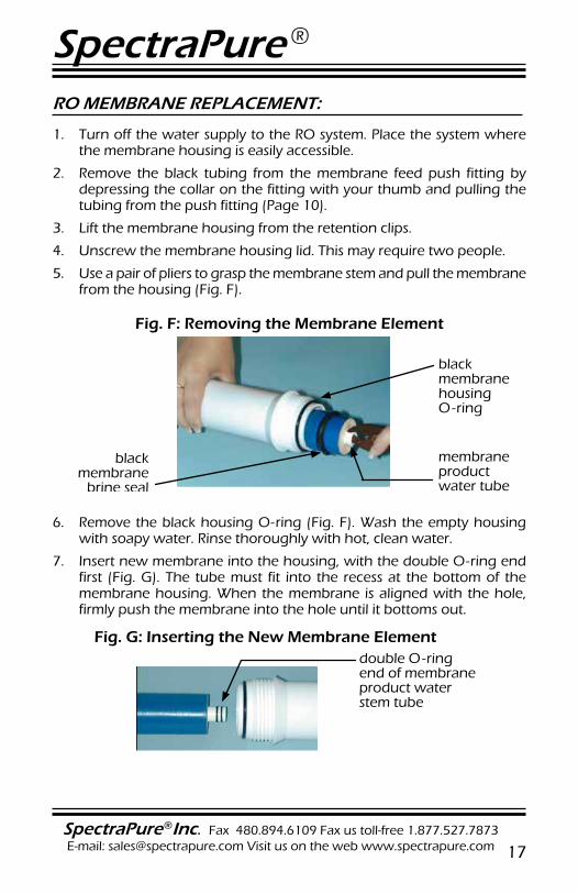
5. Use a pair of pliers to grasp the membrane stem and pull the membrane from the housing (Fig. F).
Fig. F: Removing the Membrane Element
black membrane
brine seal
black membrane housing O-ring
membrane product water tube
6. Remove the black housing O-ring (Fig. F). Wash the empty housing with soapy water. Rinse thoroughly with hot, clean water.
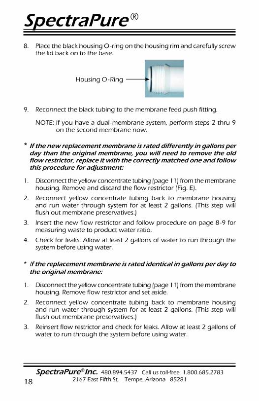
7. Insert new membrane into the housing, with the double O-ring end first (Fig. G). The tube must fit into the recess at the bottom of the membrane housing. When the membrane is aligned with the hole, firmly push the membrane into the hole until it bottoms out.
Fig. G: Inserting the New Membrane Elementdouble O-ring end of membrane product water stem tube
SpectraPure ®
SpectraPure®Inc. 480.894.5437 Call us toll-free 1.800.685.2783 2167 East Fifth St, Tempe, Arizona 8528118
8. Place the black housing O-ring on the housing rim and carefully screw the lid back on to the base.
9.
Housing O-Ring
Reconnect the black tubing to the membrane feed push fitting.
NOTE: If you have a dual-membrane system, perform steps 2 thru 9 on the second membrane now.
* If the new replacement membrane is rated differently in gallons per day than the original membrane, you will need to remove the old flow restrictor, replace it with the correctly matched one and follow this procedure for adjustment:
1. Disconnect the yellow concentrate tubing (page 11) from the membrane housing. Remove and discard the flow restrictor (Fig. E).
2. Reconnect yellow concentrate tubing back to membrane housing and run water through system for at least 2 gallons. (This step will flush out membrane preservatives.)
3. Insert the new flow restrictor and follow procedure on page 8-9 for measuring waste to product water ratio.
4. Check for leaks. Allow at least 2 gallons of water to run through the system before using water.
* If the replacement membrane is rated identical in gallons per day to the original membrane:
1. Disconnect the yellow concentrate tubing (page 11) from the membrane housing. Remove flow restrictor and set aside.
2. Reconnect yellow concentrate tubing back to membrane housing and run water through system for at least 2 gallons. (This step will flush out membrane preservatives.)
3. Reinsert flow restrictor and check for leaks. Allow at least 2 gallons of water to run through the system before using water.
SpectraPure®Inc. Fax 480.894.6109 Fax us toll-free 1.877.527.7873E-mail: [email protected] Visit us on the web www.spectrapure.com 19
SpectraPure ®
MAXCAP DI MAINTENANCE AND REPLACEMENT:
Procedure:
1. When the reading on the right-hand TDS meter (set to “IN”) displays 50% of the reading on the left-hand TDS meter (set to “OUT”), it is time to replace the MAXCAP ® DI cartridge.
2. Make sure the DI cartridge is installed in the correct direction as marked on the cartridge shell and be sure that the top seal is securely attached to the top of the cartridge.
3. Tighten the cartridge housing by rotating it clockwise and hand tighten.
4. Turn on system and check for leaks.
SILICABUSTER MAINTENANCE AND REPLACEMENT:
Procedure:
1. When the reading on the right-hand TDS meter (set to “OUT”) displays “001”, it is time to replace the SilicaBuster™ DI cartridge.
2. Make sure the DI cartridge is installed in the correct direction as marked on the cartridge shell and be sure that the top seal is securely attached to the top of the cartridge.
3. Tighten the cartridge housing by rotating it clockwise and hand tighten.
4. Turn on system and check for leaks.
DM-1 METER Specifications:
Range 0-1999 PPMResolution 1PPM (1-999 PPM)Accuracy 2%Probe 0.25 inchesPower Source (2) 1.5V button batteries (A357 or equiv.)Battery life Approx 1000 hours
For service or repair of these monitors, please send to:
HM DIGITAL, INC5819 Uplander WayCulver City, CA 90230
SpectraPure ®
SpectraPure®Inc. 480.894.5437 Call us toll-free 1.800.685.2783 2167 East Fifth St, Tempe, Arizona 8528120
SYSTEM TROUBLESHOOTING GUIDE
1. Low production rate:
a. plugged prefilters. i. Replace prefilters.
b. low water temperature ii. Warm feed water OR use higher GPD membrane.
c. low line pressure. iii. Use booster pump OR use higher GPD membrane.
d. high TDS content. iv. Use booster pump OR use higher GPD membrane.
e. fouled membrane. v. Replace membrane to restore flux.
f. plugged flow restrictor. vi. Replace flow restrictor & membrane.
2. Zero production rate:
a. Missing flow restrictor. i. Install flow restrictor in the yellow line.
b. Dried RO membrane. ii. Try to restore flux by soaking in rubbing alcohol OR replace the membrane.
c. Plugged flow restrictor. iii. Replace flow restrictor and replace the membrane.
d. Flush Valve is open. iv. Close Flush Valve.
3. Extremely high production rate:
a. Ruptured membrane. i. Replace membrane.
b. Very high line pressure (> 80 psi).
ii. Use a pressure regulator.
4. Pressure gauge does not register pressure when the system is “ON”
a. Missing flow restrictor. i. Put flow restrictor in the yellow line.
b. Pressure gauge screwed in too far.
ii. Unscrew pressure gauge one-half turn and retest.
c. Plugged pressure gauge orifice. iii. Clean orifice with a needle.
d. Defective pressure gauge. iv. Replace it.
5. Low deionization cartridge life:
a. Defective membrane. i. Replace it
b. Low pressure (< 40 psi). ii. Use booster pump.
c. High CO2 levels in water (> 5 ppm).
iii. Aerate RO product water.
d. High TDS in feed water (> 1000 ppm).
iv. NO EASY SOLUTION.
e. Bad or faulty DI cartridge. v. Replace DI cartridge.
f. High pH tap water (> 9.0). vi. Acidify feed water to the RO membrane to improve its rejection.
g. Faulty monitor/probe. vii. Test and Replace if required.
SpectraPure®Inc. Fax 480.894.6109 Fax us toll-free 1.877.527.7873E-mail: [email protected] Visit us on the web www.spectrapure.com 21
SpectraPure ®
MAINTENANCE:
SANITIZING SYSTEM
( It is recommended that you sanitize the system once a year.)
1. Turn tap water source off and remove all filters from the system, including the RO membrane
2. Mix together hot water, soap and a little bleach.
3. Scrub filter housings and rinse with clean tap water to remove soap and bleach.
4. Place filters back into housings and reconnect lines.
TIPS FOR LONG MEMBRANE LIFE
1. Replacement of 0.5 micron sediment filter once every 6 months. This will prevent mem brane fouling due to silt or sediment depositing on the membrane.
2. Replacement of 0.5 micron carbon block filter at least once every 6 months or when chlorine breakthrough occurs. This will ensure good membrane life and protect the membrane from chlorine damage.
3. Membrane should not be operated at lower than the recommended concentrate to purified water ratios, as described on page 7.
4. Operating reverse osmosis systems on softened feedwater greatly reduces the chances of membrane fouling.
SpectraPure ®
SpectraPure®Inc. 480.894.5437 Call us toll-free 1.800.685.2783 2167 East Fifth St, Tempe, Arizona 8528122
STORAGE:
1. It is recommended that you store your RO System i n a c o o l p l a c e when not being used. (a Flush Valve Kit is recommended for manually operated systems)
2. If your system is exposed to sunlight you will grow algae in the housing and it may damage your system. Your RO System must be protected from freezing or temperatures above 100° F (38°C).
3. MEMBRANE WARNING: All SpectraPure RO membranes, except for encapsulated membranes, must remain moist at all times. It is the customer’s responsibility to inspect the membrane upon receipt and maintain adequate moisture.
Replacement membranes should be kept in the sealed non-permeable shipping bag and in a refrigerator until use. The membrane can be kept there for up to 1 year. (DO NOT FREEZE)
CHOOSING A MOUNTING LOCATION:
When considering a location for the installation of the RO System, consider the following factors:
Light Sources
1. Most of the components of this system are plastic and are subject to damage by ultraviolet light from the sun and other sources such as metal halide lighting.
2. Algae is more likely to thrive inside the clear filter housings when exposed to bright light.
3. Avoid installing this unit in bright light or direct sunlight.
Temperature Extremes1. The unit must be kept out of areas that are subject to freezing
temperatures.
2. High temperatures greater than 100° F (38° C) must be avoided. If the unit is used outside, avoid putting the systemin direct sunlight or connecting it to a garden hose that may be exposed to sunlight.
SpectraPure®Inc. Fax 480.894.6109 Fax us toll-free 1.877.527.7873E-mail: [email protected] Visit us on the web www.spectrapure.com 23
SpectraPure ®
THREE YEAR MANUFACTURERS WARRANTY
SpectraPure, Inc.® warrants the product to the original owner only to be free of defects in material and workmanship for a period of three years from the date of receipt. SpectraPure’s liability under this warranty shall be limited to repairing or replacing at SpectraPure’s option, without charge, F.O.B. SpectraPure’s factory, any product of SpectraPure’s manufacture. SpectraPure will not be liable for any cost of removal, installation, transportation or any other charges which may arise in connection with a warranty claim. Products which are sold but not manufactured by SpectraPure are subject to the warranty provided by the manufacturer of said products and not by SpectraPure’s warranty. SpectraPure will not be liable for damage or wear to products caused by abnormal operating conditions, accident, abuse, misuse, unauthorized alteration or repair or, if the product was not installed in accordance with SpectraPure’s or other manufacture’s printed installation and operating conditions, or damage caused by hot water, freezing, flood, fire or acts of God.
SpectraPure will not be responsible for any consequential damages arising from installation or use of the product, including any water or mold damage due to flooding which may occur due to malfunction or faulty installation, including, but not limited to failure by installer to over- or under-tighten fittings, housings, and/or push-style fittings, or improper installation of push-style fittings. Consumable items such as pre filters and membranes are not covered under the two year warranty.
SpectraPure warrants (prorated) the performance of tested SpectraSelect™ RO membrane elements only, for one year from date of receipt by the buyer, providing that the loss of performance was not caused by fouling , neglect or water conditions exceeding the feed water parameters listed in the applicable product manual (refer to detailed membrane warranty information). SpectraPure will, on confirmation of loss of performance during the warranty period, credit the prorated amount of the current catalog price of the element. The disposable filters and cartridges are not covered under the warranty.
To obtain service under this warranty, the defective system or components must be returned to SpectraPure with proof of purchase, installation date, failure date and supporting installation data. Any defective product to be returned to the factory must be sent freight prepaid; documentation supporting the warranty claim and a Return Goods Authorization (RGA) number must be included. SpectraPure will not be liable for shipping damages due to the improper packaging of the returned equipment and all returned goods must also have adequate insurance coverage and a tracking number.
SpectraPure will not pay for loss or damage caused directly or indirectly by the presence, growth, proliferation, spread or any activity of “fungus”, wet or dry rot or bacteria. Such loss or damage is excluded regardless of any other cause or event that contributes concurrently or in any sequence to the loss. We will not pay for loss or damage caused by or resulting from continuous or repeated seepage or leakage of water, or the presence or condensation of humidity, moisture or vapor, that occurs over a period of 14 days or more. “Fungus” and “fungi” mean any type or form of fungus or Mycota or any by-product or type of infestation produced by such fungus or Mycota, including but not limited to, mold, mildew, mycotoxins, spores, scents or any biogenic aerosols.
SpectraPure will not be liable for any incidental or consequential damages, losses or expenses arising from installation, use, or any other causes. There are no expressed or implied warranties, including merchantability or fitness for a particular purpose, which extend beyond those warranties described or referred to above.
* The three year limited warranty does not apply to consumable items, including but not limited to, filters and cartridges unless specifically stated above
SpectraPure ®
SpectraPure®Inc. 480.894.5437 Call us toll-free 1.800.685.2783 2167 East Fifth St, Tempe, Arizona 8528124
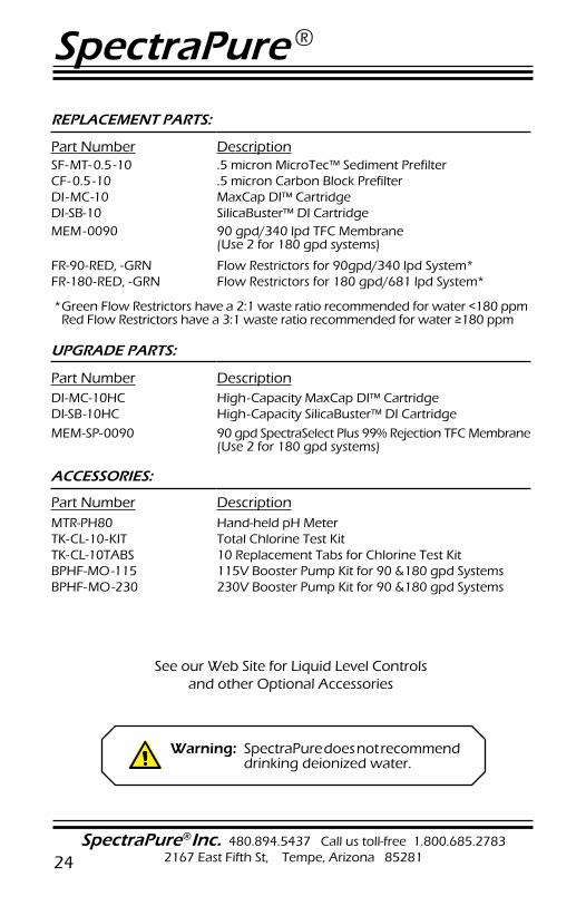
REPLACEMENT PARTS:
Part Number DescriptionSF-MT- 0.5 -10 .5 micron MicroTec™ Sediment PrefilterCF-0.5 -10 .5 micron Carbon Block PrefilterDI -MC-10 MaxCap DI™ CartridgeDI-SB-10 SilicaBuster™ DI CartridgeMEM-0090 90 gpd/340 lpd TFC Membrane
(Use 2 for 180 gpd systems)
FR-90-RED, -GRN Flow Restrictors for 90gpd/340 lpd System*FR-180-RED, -GRN Flow Restrictors for 180 gpd/681 lpd System*
* Green Flow Restrictors have a 2:1 waste ratio recommended for water <180 ppm Red Flow Restrictors have a 3:1 waste ratio recommended for water ≥180 ppm
UPGRADE PARTS:
Part Number DescriptionDI-MC-10HC High-Capacity MaxCap DI™ CartridgeDI-SB-10HC High-Capacity SilicaBuster™ DI Cartridge
MEM-SP-0090 90 gpd SpectraSelect Plus 99% Rejection TFC Membrane (Use 2 for 180 gpd systems)
ACCESSORIES:
Part Number DescriptionMTR-PH80 Hand-held pH MeterTK-CL-10-KIT Total Chlorine Test KitTK-CL-10TABS 10 Replacement Tabs for Chlorine Test KitBPHF-MO-115 115V Booster Pump Kit for 90 &180 gpd SystemsBPHF-MO-230 230V Booster Pump Kit for 90 &180 gpd Systems
See our Web Site for Liquid Level Controls and other Optional Accessories
Warning: SpectraPure does not recommend drinking deionized water.