Embed Size (px)
Citation preview

ClRlA Report 131 1993
/
The measurement of methane and other gases from the ground
D Crowhurst and S J Manchester Fire Research Station Building Research Establishment
n BUILDING RESEARCH ESTABLISHMENT, GARSTON, WATFORD W D 2 7JR Tel: 0 9 2 3 8 9 4 0 4 0 Telex: 9 2 3 2 2 0 Fax: 0 9 2 3 6 6 4 0 1 0
CONSTRUCTION INDUSTRY RESEARCH AND INFORMATION ASSOCIATION 6 Storey’s Gate, Westminster, London SW1 P 3AU Tel 0 7 1 - 2 2 2 8891 Fax 071-222 1 7 0 8

Summary
Methane and the gases often found with it can cause many problems during construction operations such as tunnelling and building in the vicinity of landfill sites. At whatever stage of the construction process, from initial investigation to the operation of the completed works, if there is reason to suspect the presence of these gases, it will be necessary to be sure of safety. This report describes the methods and techniques that are available for the detection of these gases, for sampling them and for taking measurements relevant to mitigating the problems the gases pose.
While centred on methane and landfill gas, the report also covers carbon dioxide and other hazardous gases. Within the context of safe working, there is comprehensive guidance on detecting gas, identifying the source, measuring and sampling different gases, and on the interpretation of the results. Factors which affect the investigation of gas, e.g. meterological conditions, gas in groundwater, are discussed. The use of monitoring systems on a site and within buildings is described. In addition to the cited references, an Appendix lists standards and codes relevant to safety in site investigations for gas.
CROWHURST, D and MANCHESTER, S J The measurement of methane and other gases from the ground Construction Industry Research and Information Association CIRIA Report 13 1, 1993
Keywords: Methane, gases, measurement
Reader interest: All waste disposal and environmental professionals, developers
All rights reserved. No part of this publication may be reproduced or transmitted in any form or by any means including photocopying and recording, without the writ ten permission of the copyright holder, application for which should be addressed to the publishers. Such writ ten permission must also be obtained before any part of this publication is stored in a retrieval system of any nature.
ISBN 0 86017 3720
ISSN 0305 408X
@ CIRIA 1993
CLASSIFICATION
AVAILABILITY Unrestricted
CONTENT Report
STATUS Committee Guided
USER Construction professionals
2
Published by Construction Industry Research and Information Association, 6 Storey's Gate, Westminster, London SWlP 3AU in association with Building Research Establishment, Garston, Watford, Herts. WD2 7JR.
ClRlA Report 131 '

Foreword
CIRIA’s research programme Methane and Associated Hazards to Construction is intended to provide guidance for the construction industry.
In addition to the publication of a bibliography relevant to methane and construction (CIRIA Special Publication 79) and a study of the construction industry’s needs for research and information on methane (CIRIA Project Report 5) , the programme includes the preparation of two further guidance documents: this report and a companion report on the nature, origins, occurrence and hazards of methane (CIMA Report 130). Current additional projects deal with the protection of developments from methane and associated gases in the ground and with the investigation of sites where these gases may be present.
This report is the result of the third project in the programme. It was prepared by Dr D Crowhurst and Mr S J Manchester of the Fire Research Station of the Building Research Establishment, under contract to CIRIA.
CIRIA is pleased to acknowledge the contribution to this report arising from longstanding and current work at the Building Research Establishment funded by the Department of the Environment on the potential hazards of landfill gases to construction.
Following CIRIA’s usual practice, the research was guided by a Steering Group which comprised:
Mr M G Glynn (Chairman) Mr K V Ansell Mr D L Barry Dr J S Edwards Mr D Grant Mr R A B Hall Mr C P Hill Mr A Parker Dr J S Sceal Mr A A Smith Mr R Thompson Mr R C Weeks
- North West Water - McAlpine Laboratories - W S A t k i n ~ - University of Nottingham - Department of the Environment - Mott MacDonald Environmental Services - West Yorkshire Waste Management - Gibb Environmental Sciences - Wardell Armstrong - Clayton Environmental Consultants - London Waste Regulatory Authority - Geotechnical Instruments
CIRIA’s research managers for this project were Mr F M Jardine and Mr R Freer.
The project was funded under Phase I of the programme of Methane and Associated Hazards to Construction by:
Department of the Environment, Construction Directorate National House-Building Council Anglian Water Services Ltd Northumbrian Water Services Ltd North West Water Ltd Southern Water Services Ltd Thames Water plc Welsh Water plc Yorkshire Water Services Ltd Kyle Stewart Design Services Ltd Sir Robert McAlpine & Sons Ltd
ClRlA Report 131
CIRIA and Fire Research Station are grateful for help given to this project by the funders, by the members of the Steering Group and by the many individuals and organisations who were consulted.
3

4
Acknowledgements
Figure 12 reproduced with the permission of Gordon and Breach Science Publishers. Figure 19 reproduced with the permission of Supply and Services Canada (1 992).
J
ClRlA Report 131

Contents
List of Figures List of Tables Glossary Abbreviations
1 INTRODUCTION 1.1 Background 1.2 Scope 1.3 How to use this document
2 SOURCES OF HAZARDOUS GASES 2.1 Methane
2.1.1 Landfill gas 2.1.2 Marine sediments 2.1.3 Wetlands 2.1.4 Sewer gas 2.1.5 Mine gases 2.1.6 Groundwater 2.1.7 Natural gas (piped mains gas) 2.1.8 Other sources
2.2 Carbon dioxide 2.3 Hydrogen sulphide 2.4 Carbon monoxide 2.5 Other gases 2.6 Need for investigation 2.7 Summary
3 SAFETY 3.1 Introduction 3.2 General guidance - equipment 3.3 General guidance - sampling points 3.4 COSHH
4 LOOKING FOR GAS - PLANNING AN INVESTIGATION 4.1 Introduction 4.2 Site investigation - the first stage
4.2.1 Desk study 4.3 Visual assessment
4.3.1 Aerial false colour infra-red photography 4.3.2 Aerial thermography
4.4 Second-stage investigation 4.5 Third-stage investigation 4.6 Fourth-stage investigation - post-development monitoring 4.7 Summary
5 INTERPRETING THE RESULTS OF AN INVESTIGATION 5.1 Introduction 5.2 Understanding the measurements 5.3 Assessing the results 5.4 A ‘safe’ concentration 5.5 Interpreting emission rate measurements 5.6 Summary
8 8 9
11
13 13 13 13
14 14 14 15 15 15 15 15 15 16 16 16 16 16 17 17
18 18 18 18 19
21 21 21 21 23 24 25 26 27 27 27
29 29 30 31 32 33 33
ClRlA Report 131 5

6 MEASURING GAS - IDENTIFYING THE SOURCE 6.1 Introduction 6.2 Identification from composition
6.2.1 Gas chromatography 6.2.2 Mass spectrometry
6.3.1 Carbon 14 dating 6.3.2 Stable isotope measurements
6.3 Identification by age and formation process
6.4 Summary
7 MEASURING GAS - CHOOSING INSTRUMENTATION 7.1 Introduction 7.2 Choosing an instrument
8 MEASURING GAS - A SAMPLING METHODOLOGY 8.1 Introduction 8.2 Pre-site checks 8.3 Daily on-site checks 8.4 Actions at each sampling point 8.5 Summary
9 MEASURING METHANE 9.1 Introduction 9.2 Infra-red absorption
9.2.1 Laser detection systems 9.2.2 Ultra-sensitive detectors
9.3 Catalytic instruments 9.4 Combined catalytic/thermal conductivity devices 9.5 Flame ionisation instruments 9.6 Semiconductor gas detectors 9.7 Chemical detector tubes
10 MEASURING OTHER GASES 10.1 Introduction 10.2 Carbon dioxide
10.2.1 Infra-red instruments 10.2.2 Thermal conductivity instruments 10.2.3 Chemical detector tubes
10.3.1 Electrochemical cells 10.3.2 Paramagnetic instruments 10.3.3 Davy lamp
10.4.1 Hydrogen sulphide 10.4.2 Carbon monoxide 10.4.3 Hydrogen
10.5 Multiple gas detection 10.5.1 Portable analysis kits 10.5.2 Portable gas chromatographs
10.3 Oxygen
10.4 Hydrogen sulphide, carbon monoxide and hydrogen
10.6 Summm
11 GAS SAMPLING POINTS 11.1 Introduction 11.2 Temporary sampling points
11.2.1 Simple spiking 11.2.2 Shallow probes
1 1.3.1 Shallow probes 1 1.3.2 Deep driven probes
11.3 Permanent and semi-permanent sampling points
34 34 34 35 36 36 36 37 38
39 39 39
42 42 42 42 42 44
45 45 45 47 48 48 50 52 53 53
55 55 55 55 56 57 57 57 58 58 59 59 59 59 59 59 60 60
61 61 61 61 61 63 63 64
I 6 ClRlA Report 131

1 1.4 Boreholes 11.5 Trial pits 1 1.6 Surface sampling apparatus 11.7 Summary
12 SAMPLE COLLECTION 12.1 Introduction 12.2 Groundwater level 12.3 Sample system - on site measurement 12.4 Sample collection for off-site analysis 12.5 Materials
12.5.1 Tubing 12.5.2 Drying agents 12.5.3 Sampling vessels for sample collection
12.6 Sampling by adsorbent media 12.7 Summary
13 METEOROLOGICAL DATA 13.1 Meteorological effects
13.1.1 Temperature 13.1.2 Atmospheric pressure/rain€all 13.1.3 Other effects
13.2 Summary
14 METHANE IN GROUNDWATER 14.1 Introduction 14.2 Sample collection 14.3 Measurement
14.3.1 Direct aqueous injection gas chromatography 14.3.2 Vacuum degassing gas chromatography 14.3.3 In-situ measurement
14.4 Summary
15 EMISSION RATE MEASUREMENT 15.1 Introduction 15.2 Direct measurement
15.3 Flow velocity measurement 15.4 Indirect methods
15.4.1 Recirculation 15.4.2 Flux box measurement
15.2.1 Volume flow measurements
15.5 Summary
16 CONTINUOUS MONITORING SYSTEMS 16.1 Introduction 16.2 Central sequential 16.3 Local sequential 16.4 In-place sensor 16.5 Summary
17 MONITORING IN BUILDINGS 17.1 Introduction 17.2 Detection systems 17.3 Sensor location 17.4 Summary
66 69 70 70
72 72 72 72 73 75 75 76 76 76 76
77 77 77 77 78 78
79 79 79 81 81 81 82 83
84 84 84 84 84 86 86 86 87
88 88 88 89 89 90
91 91 91 91 93
References 94
ClRlA Report 131
Appendix A Standards and codes of practice relevant to safety in site investigations for gas 97
7

List of Figures
Figure 1 Figure 2 Figure 3 Figure 4 Figure 5
Figure 6
Figure 7 Figure 8 Figure 9 Figure 10 Figure 11 Figure 12 Figure 13
Figure 14 Figure 15 Figure 16 Figure 17 Figure 18 Figure 19 Figure 20 Figure 21 Figure 22 Figure 23 Figure 24 Figure 25 Figure 26 Figure 27
Figure 28 Figure 29 Figure 30 Figure 31 Figure 32 Figure 33 Figure 34 Figure 35 Figure 36
Phases in landjill gas generation Sequence of investigation for gas Conventional photograph showing variations in condition of grass False-colour infra-red photograph showing distress in trees and grass Infra-red thermogram showing methane emission adjacent to a track on a landfill site An infra-red thermogram of a site emitting methane next to a borehole and gas pipeline Methane concentrations in air - conversion of units Example record of gas measurement Signal concentration curve for catalytic sensor Detector tube Schematic diagram of a gas sampling pump Diagram of apparatus for sampling landfill gases Soil gas probe (Research Engineers Ltd) representative of the type used by Flower Shallow spiking probe Shallow probe sampling point Gas probe lejl in place afer Withdrawal of driving tube Typical borehole installation Typical gas probe tip in borehole installation Typical nested installation in one borehole Multi-probe installations Gas sampling probe Trial pit gas probe within fill Sulface sampling Gas dewatering drum Schmatic of parallel sampling system Recirculation of gas from a sampling point (a) Gas sampling cylinder (single headed) (b) Gas sampling pump (two stage) Principle of a simple collection system Components of a reservoir sampler Combined sampling and degassing apparatus Construction of difSusion cell Central sequential sampling scheme Local sequential sampling scheme In-place sensor Buoyancy of methanekarbon dioxide mixtures relative to air Gas entry into buildings
List of Tables
Table 1 Sensors of instruments for gas measurement Table 2 Methane instruments Table 3 Carbon dioxide instruments Table 4 Oxygen instruments
14 22 24 25
25
26 30 31 49 53 54 62
62 62 64 65 66 66 67 67 68 69 71 72 73 74 74 74 75 80 81 82 88 89 90 92 92
40 45 55 57
8 ClRlA Report 131

Glossary
Alkanes
Anaerobic
Bacteriogenic
Billion
Biogenic
Borehole
Catalyst
Coulometer
Cover
Electrolyte
Fissure
Flammable
Flux
Geochemical
Halogenated
Hot spots
Hydrocarbon
Inert
Ionisation
Isotope
Landfill
A group of straight chain hydrocarbons, the first four members being the gases: methane, ethane, propane and butane.
In the absence of oxygen (air).
Derived from ancient or recent microbiological activity on organic matter.
1 x 10⁹ (1 ooo ooo 000)
Derived from the action of bacteria on organic matter.
A hole drilled in or outside the wastes in order to obtain samples. Also used as a means of venting or withdrawing gas.
A substance which speeds up a chemical reaction without itself undergoing any permanent change.
An instrument for measuring the amount of charge passing in an electrical circuit.
Material used to cover solid wastes deposited in landfills.
A substance which undergoes partial or complete dissociation into ions in solution, and thus acts as a conductor of electricity.
A long MITOW cleft or crack.
Of a substance capable of supporting combustion in air.
Flow or discharge.
The result of an underground chemical reaction.
The incorporation of halogens (fluorine, chlorine, bromine, iodine) into a chemical species.
Areas of underground combustion and gas generation.
A compound containing carbon and hydrogen only.
Having only a limited ability to react chemically.
The process of changing a particle with no charge into one with a positve or negative charge, by the removal or addition of electrons.
Atoms of the same chemical element which have different atomic weight, i.e. numbers of neutrons but similar chemical properties.
The engineered deposit of waste into or on to land. It may eventually provide land which may be used for another purpose.
ClRlA Report 131 , . 9 , .

Leachate
Limits of flammability
Luft cell
Mercaptans
Microbial
Odourant
Oxidation
Paramagnetic
Peristaltic pump
Permeable
PH
Photoionisation
Pitot tube
Scintillant
Specificity
Stenching agent
Thermogenic
Topography
The result of liquid seeping through a’landfill and being contaminated by substances in the deposited waste.
Concentration range bounded by LEL and UEL (see abbreviations) within which a gas or vapour is flammable at normal atmospheric temperature and pressure.
A gas-filled cell used in some infra-red detectors to select a particular measuring wavelength.
A group of organic compounds containing sulphur which have strong and unpleasant odours.
Small organisms which are only visible under a microscope, such as bacteria, fungi and algae.
A substance with the property of effecting the nasal sense of smell.
Reaction of a species with an oxidant - normally, but not necessarily, ‘oxygen’ from the air.
The property of a substance which, when placed in a magnetic field, causes a greater concentration of the lines of magnetic force within itself than in the surrounding magnetic field.
A pump operating by successive wavelike contractions and relaxations.
Allowing the passage of a liquid or gas.
A measure of the acidity or alkalinity of a liquid.
The ejection of an electron from an atom by a quantum of electromagnetic energy.
Device used to measure speed of flow.
A substance which produces flashes of light when particles collide with it.
In the context of instrumentation implies a response to a single or unique component.
A substance adding a smell to another substance.
Derived from the temperature degradation of organic matter.
The study or description of the surface features of a region.
10 .,.
, ClRlA Report 131

Abbreviations
BASEEFA
BDA
BSI
COSHH
DIAL
IR
LEL
LIDAR
NICAT
OEL
os UEL
VOC
British Approvals Service for Electrical Equipment in Flammable Atmospheres.
British Drilling Association.
British Standards Institute.
Control Of Substances Hazardous to Health.
Differential Absorption LIDAR.
Infra-red.
Lower Explosive Limit - the lower limit of flammability, i.e. the minimum percentage by volume of a mixture of gas in air which will propagate a flame in a confined space, at normal atmospheric temperature and pressure.
Laser Radar.
Nickel Catalyst.
Occupational Exposure Limit - limits related to personal exposure to substances hazardous to health in the air of a workplace.
Ordnance Survey.
Upper Explosive Limit - the upper limit of flammability, i.e. the maximum percentage by volume of a mixture of gas in air, at normal atmospheric temperature and pressure, which will propagate flame in a confined space.
Volatile Organic Compounds.
ClRlA Report 131 1 1

1 Introduction
~~~ ~
PREVIOUS PAGE IS BLANK
1 .I BACKGROUND
This report was prepared for CIRIA by the Building Research Establishment. It forms part of work sponsored by CIRIA, industry, and the Department of the Environment which seeks to provide the construction industry with up-to-date guidance about detecting, sampling, measuring and monitoring methane and other gases that may be found in the ground.
This guidance document is one of a series of reports relating to problems of gas in the ground. The reports from other stages of the project are published separately and each document can be read independently as a report in its own right. The documents are also complementary and together provide a state-of-the-art overview of the subject.
1.2 SCOPE
This report provides guidance on the detection, measurement and monitoring of gases in the ground. Although the report is centred on methane, this gas should not be considered in isolation. Other hazardous gases such as carbon dioxide, hydrogen sulphide, carbon monoxide, and hydrogen, may be present with methane or occur separately; the report also provides guidance for these gases.
1.3 HOW TO USE THIS DOCUMENT
The main text of the report, and therefore what is considered to be essential reading for each section is presented in the normal way.
More detailed information, which may be of interest to some readers, is presented in boxes.
Comments on the main text are presented in italics.
As far as possible tables and figures accompany the relevant text.
In most cases it is intended that each section can be read as a whole, independent of other parts of the text. Where necessary, however, essential cross references are given.
A glossary of terms is included at the beginning of this report.
13 ClRlA Report 131

2 Sources of hazardous gases
The problem of hazardous gases in the ground is not limited to landfill sites and particular types of development. Although much attention has been paid to landfill gas in recent years, the potential problems for construction caused by methane in the ground are much wider.
2.1 METHANE
There are a number of different possible sources of methane that could be encountered during a development. The sections below give a brief description of these sources.
2.1 -1 Landfill gas
Landfill gas is formed by the decomposition of degradable wastes within landfill sites. Principally a mixture of methane and carbon dioxide, it also includes a large number of minor components.
The landfill gas production process passes through several stages (Figure 1) during which the composition of the gas changes significantly[']. Initial decomposition depletes the oxygen in the ground, converting it to carbon dioxide. At the start of the second stage all the oxygen has been consumed and the conditions become anaerobic, leading to the production of a mixture of carbon dioxide and hydrogen. It is not until the third stage that methane production starts (methanogenesis). The gas composition during steady-state methanogenesis is about 60 % methane and 40% carbon dioxide. Subsequently, in the final stages, gas production declines although it can continue, albeit at a much lower rate, for many years.
Time
Phase I: Aerobic decomposition of biodegradable materials: entrained atmospheric oxygen is converted to carbon dioxide. Phase 11: Anaerobic decomposition commences as oxygen is used up: carbon dioxide concentration increases and some hydrogen is produced: no methane is produced at this stage. Phase 111: Anaerobic methane production commences and rises to a peak: concentration of carbon dioxide declines: hydrogen production ceases. Phase IV: Steady methane and carbon dioxide generation in proportions of between 50-70 % and 30-50 % respectively. Phase V: Steady decline in generation of methane and carbon dioxide: gradual return to aerobic conditions.
Figure 1 Phases in landfill gas generation
14 . , ClRlA Report 131

Gas production is sensitive to a range of factors such as moisture content, oxygen content, pH, temperature and density of the waste. A more complete description of landfill gas production is given in Waste Management Paper 27[’1.
2.1.2 Marine sediments
Methane production from marine sedirnents occurs due to the anaerobic decomposition of organic matter deposited on the sea bed. Not only must there be no oxygen present for methane to be produced but dissolved sulphate must also be absent. This generally occurs at depths of tens of metres into the sediment in deep sea environments. Methane production at shallow depths is not generally found.
2.1.3 Wetlands
Areas such as marshes, peatlands, lakes and estuaries are all potential sources of methane. The gas formed in these environments predominantly consists of methane and carbon dioxide, sometimes together with hydrogen sulphide. It is formed by the anaerobic microbiological degradation of dead, usually waterlogged, vegetation. Flames of burning marsh gas are responsible for the phenomenon known as Will-0’-the-Wisp.
2.1.4 Sewer gas
The main components of sewer gas are again methane and carbon dioxide, but hydrogen sulphide may also be present. The process of formation is anaerobic decomposition of the organic putrescible components of sewage.
. .
2.1.5 Mine gases
The most common gas encountered in mines and mining areas is methane (firedamp). Geological methane is usually associated with coal-bearing carboniferous strata and is produced by the anaerobic decomposition of ancient vegetation trapped within the rock. Higher alkanes (such as ethane), hydrogen and helium may also be present.
Methane encountered during mining operations can originate from a number of
as a free gas within the seam being worked on
adsorbed on the surfaces of fissures and pores in the seam
absorbed within the internal structure of the coal
from non-coal strata such as shale or sandstone
from colliery spoil.
Unworked seams surrounding the seam being mined can also produce methane that will contribute to the hazard in the area being worked.
2.1.6 Groundwater
Under pressure, ‘methane is dissolved in groundwater and is released back into the gaseous phase when the pressure is reduced, rather like the release of gas which occurs on opening a bottle of carbonated water. There is therefore the potential for this gas to escape from solution at the ground surface or in man-made constructions such as tunnels and old mine workings. Methane in groundwater is dealt with in more detail in Section 14.
2.1.7 Natural gas (piped mains gas)
Natural (mains) gas is predominantly methane (with an added stenching agent) which has the same geological source as methane in coal mines. Leaks of this gas from fractured underground mains can be a problem, particularly if the gas subsequently migrates into buildings. The gas pipeline or other utility services often provide preferential routes for this to
ClRlA Report 131 15

During the migration of piped gas some of the methane may be oxidised to carbon dioxide.
2.1.8 Other sources
Other potential sources of methane relevant to construction include industrial wastes and certain building materials which contain organic matter. For example foundry sands, timber and paper may produce methane and carbon dioxide if they undergo anaerobic degradation.
2.2 CARBON DIOXIDE
As with methane, carbon dioxide occumng in the ground can come from a number of different sources, as follows:
landfill - carbon dioxide generally constitutes about 40% of landfill gas and is formed during the initial aerobic decomposition of the refuse, and also later during the anaerobic degradation stage
wetlands - see Section 2.1.3
sewers - see Section 2.1.4
mines - carbon dioxide (blackdamp) can be formed by the low temperature oxidation of
limestonekhalk - carbon dioxide can be produced by the action of acid waters on carbonate
carbonaceous materials
rocks as might be found in limestone and chalky areas. Creedyr3*q gives a fuller discussion of the origins of these gases underground
other materials containing organic matter - see Section 2.1.8.
2.3 HYDROGEN SULPHIDE
In North West England and the East Midlands hydrogen sulphide groundwater is a fairly common occurrence. In some major urban areas there are natural surface seepages of hydrogen sulphide, often in conjunction with natural methaneta. The primary sources of hydrogen sulphide are the anaerobic microbial action on sulphur-containing materials such as sulphates and sulphides, and refuse containing gypsum and plasterboard. Where such materials are present in landfills, there is a possibility that hydrogen sulphide may be produced.
2.4 CARBON MONOXIDE
Carbon monoxide can be produced by subterranean fires within combustible wastes such as colliery spoil, peat, and landfill material with a high organic content. Besides the problem presented by the carbon monoxide, the underground fire from which it emanates poses serious problems affecting ground stability. The gas can also be formed by the low-temperature oxidation of carbonaceous material, and hence can be encountered as a component of mine gas.
2.5 OTHER GASES
Hydrogen can be present in landfill gas in small quantities. It is formed with carbon dioxide during the anaerobic process of gas production known as Phase I1 (see Figure 1).
Landfill gas may also contain trace amounts of saturated and unsaturated hydrocarbons, halogenated compounds, organosulphur compounds and alcohols.
16 _ .
ClRlA Report 131 ” 7-

2.6 NEED FOR INVESTIGATION
An investigation for gas is likely to be required if the site:
has been used for waste disposal
is near a former or operational landfill site
is in a coal mining area
Particularly areas where mining operations have ceased and where the associated measures to control gas may not be active.
is near to other mining areas
has underlying rock strata that may be gas-bearing
is near to other sites containing putrescible organic matter, e.g. reclaimed docks, canals,
is to be a place of underground construction activity, such as tunnelling
marsh land
This is particularly important where the tunnel passes through, or in close proximity to, gas-bearing rock strata or regions where methane may be dissolved in groundwater.
It should always be remembered that the gases that may give rise to problems are not just methane and carbon dioxide from landfill sites or methane from mine workings. Other hazardous gases may be present either naturally or as a result of other activities. The nature and sources of gases in the ground are considered more fully in the CIRIA repor@ which accompanies this one.
2.7 SUMMARY
ClRlA Report 131
There are numerous hazardous gases emanating from the ground, including methane, carbon dioxide, carbon monoxide, hydrogen sulphide, hydrogen and many trace organic compounds. The sources of these gases range from those of man-made origin, such as landfill sites and sewers, to natural situations in mines and wetland areas. Hence on all sites where redevelopment is planned, an appraisal of the potential gas problems of the site and how to investigate them will be necessary.
17

3 Safety
3.1 INTRODUCTION
Safety is important in every aspect of construction, including site investigation; it is also a legal requirement that all practicable steps are taken to ensure the safety of personnel undertaking such investigations and the public.
There are regulations, codes of practice, and safety guidance documents for construction governing many activities, e.g. site investigations and tunnelling; and standards also cover the manufacture and use of some of the instrumentation described in this report. A list of relevant documents is given in Appendix A.
Safety is often a straightforward combination of common sense and good working practices. Some general guidance is given here that will assist investigators and those responsible for investigation to meet basic safety requirements. This is not meant to be comprehensive. For more detailed guidance on specific subjects the reader should refer to the documents listed in Appendix A or contact the British Standards Institution, their local offices of the Health and Safety Executive, other regulatory authorities or other experts.
3.2 GENERAL GUIDANCE -'EQUIPMENT
The following points are listed as general guidance for the safe use of equipment in site investigations for gas.
1.
2.
3.
4.
5.
All equipment used should comply with appropriate British Standards (where they apply).
Portable equipment should preferably be powered by low-voltage supplies, e.g. rechargeable batteries, which should be fully charged before going on site.
Where it is necessary to use equipment that requires AC voltage, this should be at 110V and protected by appropriate circuit breakers.
Instrumentation should preferably be BASEEFA (British Approvals Service for Electrical Equipment in Flammable Atmospheres) certified as 'Intrinsically Safe', i.e. safe for use in potentially flammable atmospheres.
Where it is necessary or desirable to use non-intrinsically safe equipment, it should first be established that the atmosphere surrounding the equipment is not flammable.
3.3 GENERAL GUIDANCE - SAMPLING POINTS
Safety regulations governing the construction, use, and maintenance of boreholes and trial pits should be followed for all sample points. The following points highlight some of the main safety problems e n c o ~ n t e r e d [ ~ ~ ~ ~ ' ~ ~ :
penetration of utility services["] (electricity, gas, water, sewerage, telephones), particularly important for hand-driven metal probes
The routes of services through an investigation area should be identified, mapped and i f necessary erposed and marked, to avoid the risk of accidental damage and potential injury to personnel which may result from the penetration of services, particularly electricity and gas. Cable detection daices are available to locate underground services, and should be used whenever a sampling point is required in the vicinity of service cables.
18 . * . ClRlA Report 131 , . .

for the safety of the public all sampling points should as far as possible be made tamper- and
excavation of contaminated material
vandal-proof
Trial pits and boreholes can lead to the dispersal of contaminants at the surface posing a considerable risk to personnel. There is also the possibility that the pit or borehole may fill with noxious liquid, which Will have to be pumped out and disposed of b@ore backjilling. When gas investigations are to be made in ground where contamination is suspected (or if contamination is found), safety precautions and systems for handling and disposal of the arisings from excavations, whether boreholes or trial pits, and for backjilling should be implemented.
chemical hazards
Chemical hazards remaining on former industrial sites are an obvious safety concern when sampling, as are less apparent contaminants such as pesticides in fields. A safe system of investigation and sampling should be devised and followed in these circumstances.
Concentrations high enough to cause symptoms such as headaches anh runny eyes may easily .occur, and should be prevented by capping sampling points. Operators of machinery who are inside enclosed cabs should ensure that there is adequate ventilation to prevent the build-up of toxic gas concentrations. At all sites under investigation for gas, the presumption that gas will be present has to underlie pll the investigation activities. During sampling, because of dilution by air, dangerous gas situations are likely to be rare. Nevertheless, the excavator and operating personnel should stand up-wind of the pit, taking care during backjilling when gas in the pit will be displaced.
Entry into sampling excavations should not be permitted. If it is necessary to enter underground chambers, measurements for toxic, flammable and oxygen gas should be undertaken beforehand to ensure safe conditions. There shou,ld also be colleagues at the surface prepared for rescue'89121.
gas emission
excavations[l21
There is the risk of the sides collapsing during the excavation of trial pits, which may not be obvious from the surface. Due care should always be taken when approaching the pit to ensure the ground is firm.
Boring and excavating in wet ground can cause splashing of contaminated water. Personnel should be provided with protective clothing or kept at a safe distance.
there should be a strict ban on smoking and naked lights on the site.
3.4 COS"
The Control Of Substances Hazardous to Health (COSHH) Regulations 1988 put an obligation on employers to assess the risks to the health of employees resulting from work involving hazardous substances. Site investigation workers will almost certainly encounter such materials, especially on landfill and industrial sites. Hence, for each site investigation a COSHH assessment should be carried out in which the following points are addressed:
1. The hazards that may be present on the site, e.g. contaminants, and the risk of a hazard occurring .
2. The type and level of monitoring necessary to quantify the hazards.
I ClRlA Report 13.1
3. The precautions that should be undertaken for each activity in which workers are exposed to hazardous substances, e.g. no-smoking areas, health surveillance, personal protective equipment.
19

,
. lnvesligaiion 4s neeoeo
L
investigation of gas emission
needed
about ground
site to ensure safe and economical
I
Y e s
7
on-snte works ,
* ' ' 'T,,
f Yes
I 1 Define objectives
I Define overall strategy I including safety considerations
1s funher Investigation
needed ?
t
provide necessary information to
enable site to be de Y e I0 p e d
,
Figure 2 Sequence of investigation for gas
. . . , 'CIRIA Report 131 22

the location of any public rights of way
Local and national libraries, and county record ofices should be able to provide Ordnance Survey maps, plans and charts.
the types and location of wastes if the site has beerfilled or is a former landfill
Important, particularly if the site has been used for the disposal of toxic and chemical wastes.
The local Waste Disposal Authority should be able to provide details of the amount and type of waste deposited, though they may not be able to ifthe site was used before 1976 when waste disposal sites were not licensed. Access to the information may in some circumstances be denied on grounds of commercial confidentiality.
Information on landfill sites operated prior to the introduction of site licensing formerly held by the Regional Water Authorities may now be available from the water companies or the National Rivers Authority.
The local Environmental Health Department or Planning Department may also be able to supply information. the nature of the underlying geology
Help on the geology and hydrogeology of the site could be obtainedfrom the water companies, British Geological Survey, and the National Rivers Authority.
if the site is in a mining area, the presence of underground mine workings and the location of disposed spoil
British Coal formerly the National Coal Board) should have records of mining activities, although these may not always be complete for an area where private mining has taken place.
Information relating to safety, e.g. the location of underground utilities and information on the presence of toxic materials, should be obtained, as far as is possible, before any on-site measurements are made.
4.3 VISUAL ASSESSMENT
A visit to the site for a visual assessment and to 'sniff' for gas, i.e. take some initial gas readings using a primary investigation instrument such as a flame ionisation detector, is essential. It should be noted, however, that being unable to detect gas by sniffing does not indicate there is not a problem. On old sites there may be no visual evidence of gas activity.
The investigation should not be limited to the site area, but should include testing around its periphery to detect any off-site migration of gases. Any positive detection of gas confirms the need for further investigation. Failure to detect gas at this stage, however, would not necessarily indicate safe conditions for any form of development. For example, there may be a low-permeability layer preventing upward movement of gas, or insufficient ground gas pressure to produce an emission of gas. .
In addition, operations on the site might reactivate or modify the gas-producing processes.
Some typical signs of gas might be:
vegetation die-back
odours
bubbling from puddles and ponds
visible water vapour plumes from cracks in the ground
areas of melted snow
signs of burning aloqg cracks
ClRlA Report 131 23

sulphur deposits
uneven settlement
signs of leachate.
Attention should also be paid to the surface topography and layout of the site. The investigator should try to correlate the documentary evidence discovered in the desk study with the existing conditions on the site.
As well as visual evidence it is also worthwhile taking some preliminary gas measurements by spiking with shallow probes and sniffing cracks and fissures for evidence of gas. This can allow quite extensive coverage of the site and may identify potential 'hot spots' of gas emission and generation.
Other techniques which may be of use in obtaining an indication of the general gas condition are described briefly below.
4.3.1 Aerial false-colour infra-red photography
This technique is based on the different infra-red radiation absorption properties of healthy and unhealthy vegetation. On a site where methane is present in the soil the vegetation is often unhealthy, grass sward being particularly affected. The distressed condition of the foliage is not always apparent to the naked eye, but it will show up when photographed using infra-red sensitive film (Figures 3 and 4). To get an accurate picture the site must be photographed from above. Helium-filled balloons['q and radio-controlled model this.
have been used for
Figure 3 Conventional photograph showing variations in condition of grass (lower left corner). By permission of Sk yscan
It should be stressed that the vegetation could be diseased from causes other than methane, such as leachate from landfill, incorrect use of pesticides and herbicides, and poor irrigatioddrainage. As the results obtained from this method are often inconclusive, it is not very widely used. The advantages of this technique are:
it is relatively inexpensive
it can be used to examine a wide area
it can be used to identify migration routes.
24 ClRlA Report 131

Healthy vegetation is a strong infra-red reflector and when photographed will appear red on the film. Distressed foliage records typically as grey-green because of its absorption of the infra-red radiation. As infra-red sensitive film also responds to visible and ultra-violet light, it is necessary to use the appropriate filters so that only images from the near infra-red (500 to 900 nanometres) part of the spectrum are formed.
Figure 4 False-colour infra-red photograph showing distress in trees and grass (seen in red). By permission of Sk yscan
4.3.2 Aerial thermography
A similar technique to aerial infra-red photography is aerial thermography['61 which involves the use of an infra-red scanner instead of a conventional camera (Figure 5, and Figure 6 at the end of Section 4).
Figure 5 Infra-red thermogram showing methane emission adiacent to a track on a landfill site. By permission of Wimpe y Environmental
ClRlA Report 131 25

This technique can be used to locate areas of underground combustion and methane generation i.e. 'hot-spots', as these areas will have higher surface temperatures than non-gas-producing areas.
The major disadvantage with this method is that it has to be carried out at night as the sun will mask any hot-spots during the day.
4.4 SECOND-STAGE INVESTIGATION
If the presence of gas on a site is confirmed by a preliminary investigation or where a site is being considered for any form of hard development, further more detailed investigation will be required to quantify the gas problem.
By the end of this part of the examination the investigator should aim to have a clear idea of the gas regime and be able to advise a developer of the potential hazards from any sources of gas and give some indication of the degree of protection that is likely to be required for the proposed development.
The following basic measurements and supporting information are required at this stage:
gas composition
gas concentration
gas emission rates
the likely variation in the above as a result of normal meteorological changes
variations with time
identification of the source of gas
the extent of any lateral migration
the presence of methane or other gases in the groundwater
the nature of the waste
the geologyfiydrogeology of the site.
In order to achieve this, the investigator will have to employ a variety of techniques and types of instrumentation to build up a picture of the overall site conditions.
The instrumentation and techniques for constructing sampling points and sampling methods are discussed in detail in Sections 7 to 12.
The choice of which technique to use will be governed by the nature of the information needed and the requirement to protect the health and safety of the workers, the public and the environment.
26 . . .. r' '
ClRlA Report 131

4.5 THIRD-STAGE INVESTIGATION
This is essentially a continuation of the second-stage investigation through the construction phase of a development. It is designed to determine quickly any changes that occur to the gas regime as a result of construction work or other changes in the site conditions. The location of sampling points should reflect the detail of the development.
4.6 FOURTH-STAGE INVESTIGATION - POST-DEVELOPMENT MONITORING
If gas is being produced it would be prudent to assume that structures erected on the site could be affected on a long-term basis and that monitoring may be necessary. For this reason, long- term (30 + years) post-development monitoring of sites and buildings should be considered and may be essential to:
check that the installed gas-protection measures are working
enable early detection of a hazardous situation arising
confirm there is no off-site migration that may adversely affect adjacent properties.
The monitoring of gases in buildings is considered in more detail in Section 17
4.7 SUMMARY
1 In circumstances where gas might reasonably be expected to be present on a site and where redevelopment of the land is being considered, an investigation to assess the gas condition will be required. Under these circumstances a preliminary investigation should be carried out. This
. ' should contain two essential elements:
1. A desk study related to the conditions of the site and its surroundings.
2. A visual assessment of the site together with some preliminary measurements of gas.
On the basis of the findings from this part of the investigation the requirements and planning of further investigative work may be assessed. This will include a more detailed search involving sub-surface sampling of the site to gather information on gas composition, concentration and emission rate. The third stage involves the continued monitoring of the site throughout the construction of the development. If gas is being produced, then long-term post development monitoring should be considered to maintain safe conditions both on- and off-site.
ClRlA Report 131 27

..
The scanner detects the infra-red radiation that all objects naturally emit. The amount of radiant energy given off increases with higher surface temperatures. A visual heat picture is then produced on a monitor in which the colour shading corresponds to the changes in the surface temperature of the area being scanned.
Figure 6 An infra-red thermogram of a site emitting methane next to a borehole and gas pipeline. By permission of Wimpey Enviromental
28 . . ClRlA Report 131

5 Interpreting the results of an investigation
5.1 INTRODUCTION
It may seem out of sequence to consider the interpretation and assessment of the results of an investigation before considering the means by which measurements are made and data obtained. However, interpreting the results is the most difficult part of any investigation, and an appreciation of the difficulties involved in this task is vital. It will help in defining the requirements of the investigation, ensure that appropriate measurements are obtained and assist those who use the results to assess the quality of the information and data provided.
The purposes of an investigation and, hence, the basis for the interpretation of the data are:
to define quantitatively the conditions on the site
to use that quantitative data to assess the need for measures to mitigate the gas problem
to use the quantitative data as the basis for the design of protection systems should they be required.
The gas-protection system must maintain safe conditions inside the building regardless of changes in the external conditions. The essential problem in assessing the site investigation data is establishing reasonable criteria based on measurable parameters (composition, concentration and emission rate) which can be used for the design of effective gas-control systems.
Before examining this problem in more detail the following general comments are worth making:
1. For a gas which is potentially flammable and/or asphyxiating andlor toxic, between the source of the gas and clean air there will exist a mixture which is flammable and/or asphyxiating and/or toxic.
2. The flammable and/or asphyxiating and/or toxic mixture may not necessarily be at a location where it poses any threat, e.g. if a mixture in the ground is flammable it does not pose any threat provided it remains in the ground and does not extend to any other location where it may contact an ignition source.
3. When diluted to a concentration which is below the flammable, asphyxiant and toxic concentration, the gas mixture no longer represents a hazard.
These statements may appear obvious but they are the only basis on which the safety of a site and its development can be judged.
If a site is generating or contains gas, and development is proposed, the problem that needs to be resolved is not: ‘Is the site safe?’, but rather: ‘Can additional measures be incorporated into the development to make and keep it acceptably safe for the end-user and neighbours?’
So-called trigger concentrations have been set for some types of contamination other than gases, which, if exceeded, may require some appropriate remedial action to be taken. This may be appropriate for some forms of chemical contamination where the extent of contamination can be defined and dealt with. This is not possible with gas contamination because the generation process is in a continuous state of flux. Thus, an apparently ‘safe’ site may, as a result of changing conditions, become ‘unsafe’.
It should always be remembered that the conditions of ultimate relevance to the safety of a development are those occurring once the, redevelopment programme is complete, not those at the start. This is true, and independent of, any measurements and safety precautions taken before and during the development period.
ClRlA Report 131 29

5.2 UNDERSTANDING THE MEASUREMENTS
The first problem for many people in interpreting a report of a site investigation is actually understanding the details of the measurements taken. Results of an investigation may be presented in many different formats with measurements quoted in a variety of units. For example, the concentration of methane may be given as ppm v/v (parts per million by volume), % LEL (percent lower explosive limit), or % v/v (percent volume). Ideally all measurement should be related back to a common scale, preferably % volume. There is some advantage in the use of the LEL scale to measure for flammable gases, as it is the scale that appears on many instruments. It is also directly related to the hazard and independent of the actual volume. To obtain an accurate conversion from % LEL to % volume the exact nature of the gas mixture must be known.
Figure 7 shows how these units of measurement are related for methane, although it must be realised that the % LEL values are strictly valid only for methane in air and will be different for other flammable gases and gas mixtures.
5 10 (15120 50 100 Ol0 by volume 0.1 0.5 1 I I I I I
LEL ("EL, I I I I I
2 10 20 100 o/o LEL in air I
I I I I I I
I I L
Parts per million by volume I I I I I I I 1 1 1 1 l 1 I I l l
I * 1000 5000 10,000 50,000
Figure 7 Methane concentrations in air - conversion of units
The report of an investigation should give full details of the measurements taken, i.e.:
how - is the instrumentationused
where - is the location, type and depth of the sampling point
when - the date and time of the measurements
the weather conditions prevailing at, before, and after the time of measurement.
The report should also give details of the sampling and measurement protocol followed, the calibration details of the instrumentation and the type of sampling point.
This information will help to maintain comparability should further measurements be required, help the user of an investigation report to be sure that the investigation has been carried out in a competent manner, and ensure that the results are reliable.
Figure 8 gives an example of the sort of information that should appear in the results log of an investigation report. It is not meant to represent the only way of presenting the results, but indicates what is considered to be the minimum required information.
30 ClRlA Report 131 I . I

Name of site:
Sample point ref.:
Sample point location:
METEOROLOGICAL DATA
Air temperature (0C):
Atmospheric pressure:
Weather conditions (i.e. sun, rain, overcast):
Wind speedldirection:
GAS DATA
Detection instrument used:
Gas measured:
Concentration recorded:
Scale:
Time reading was taken:
Sampling method used (e.g. borehole, trial pit, probe):
Name:
Signed:
Date:
Figure 8 Example record of gas measurement
5.3 ASSESSING THE RESULTS
There are three important questions to ask in assessing and interpreting the results from the investigation of a gas problem:
1. How are data collected from point-source measurements related to the overall site conditions?
2. How are the data from measurements of ground conditions and emission rates related to what might migrate and appear in a building?
3. Do the data indicate that the site is acceptably safe for the development proposed?
Measurements from individual sampling points at best only give a measure of the conditions at that location at the time of measurement.
To characterise the gas regime on a site fully would require many measurements at many locations over long periods. This, in most ;stances, will be practically and economically impossible to achieve. However, a reasonable number of measurements made using techniques
ClRlA Report 131 31
32
and methods described in the body of this report will, if camed out correctly, provide an adequate overall assessment of the ground-gas conditions of the site.
The relationship between the gas conditions in the ground and what might ultimately appear in a building is extremely complex. It depends on a large number of changing variables and is not well understood. With the present state of knowledge it is not possible to give definitive advice and guidance on this subject. It is only possible to say that where a potentially hazardous gas concentration is in the ground, then there is the potential for hazard to construction works on, in or near that ground unless actions are taken to prevent it.
5.4 A ’SAFE‘ CONCENTRATION
The question still remains: ‘What is a safe concentration?’.
‘Safe’ conditions for inside buildings can be defined as follows:
A safe condition is one where the concentration of a gas never exceeds its LEL or its long-term Occupational Exposure Limit (OEL) or the concentration at which the atmosphere becomes asphyxiating.
It follows that strictly the only safe site is one where the concentration of a gas, whenever and wherever measured, is found to be below these values and can be guaranteed to remain so. Even if such sites exist, the available techniques for measurement would not establish this beyond doubt, much less guarantee the continuance of safe conditions. It must, therefore, be concluded that no site which is susceptible to the presence of gases in the ground can be, considered safe with absolute confidence. This being the case, an alternative approach to take is: ‘What is an acceptable concentration that gives an adequate margin of safety?’.
It is not easy to define the margin of safety on any of these values (i.e. LEL, OEL, asphyxiating concentration) which makes it desirable, advisable or essential to take actions to mitigate them or their effects, and to ensure that conditions remain safe.
For flammable gases in an industrial environment an upper concentration limit of 20 % LEL is often recommended. If this is set as an ‘alarm’ value, when the concentration of a flammable gas begins to increase, an early warning will allow action to be taken to prevent a hazard arising. In the case of gases from the ground entering a building, a similar system might be used to trigger an automatic ventilation system.
Where safety is reliant on passive protection a greater safety margin is advisable. This can be achieved with a two-level alarm system: a low alarm level, perhaps as low as 10% LEL which indicates a rising concentration but at which no immediate action is required, and a high alarm level, say 20% LEL, at which a building would be evacuated.
A similar argument may be applied to the presence of toxic gases if encountered at concentrations in excess of say 25% of their OEL. For the most commonly encountered asphyxiant/toxic gas, carbon dioxide, the long-term OEL is 0.5% by volume. Therefore a concentration in excess of 0.125 % by volume of carbon dioxide would perhaps give cause for concern.
The presence of other gases or materials above 25% of their long-term OEL would also lead to the designation of a site as ‘unsafe on toxic grounds’.
These ‘alarm’ concentrations are concentrations measured in the building itself. They are not necessarily the concentration in the ground surrounding the building. If protection measures are working effectively then concentrations of gas in the ground well in excess of these values may be tolerable if not desirable.
. . . ClRlA Report 131

5.5 INTERPRETING EMISSION RATE MEASUREMENTS
The interpretation and assessment of emission rate data is even more difficult and less well understood than that of concentration measurement.
In assessing the total emission rate from the surface area of a site, an extremely pessimistic view would be to take the maximum flow rate of methane measured at any one borehole. (Note: this will depend on both the concentration and observed total volume flow rate.) This value is then corrected to give the emission rate/m2 for the whole site. This may seem a drastic assumption, but two-hundredfold increases in flow rate have been observed from the same borehole from one measurement to another.
An alternative, less conservative, approach is to assume that the maximum volume flow rate from one borehole is equivalent to the flow from 10m2 of the surrounding surface. This means that a single size borehole must be adopted as a standard for all measurements, if results are to be directly comparable. It also requires considerable interpolation to estimate the emission rate over the whole surface.
5.6 SUMMARY
Interpreting the results is the most difficult part of an investigation. It should seek to provide an overall picture of the gas activity on the site, so that effective gas control measures can be implemented. An investigation report should give full details of the measurements taken, the sampling and measurement protocol used, instrument calibration details and type of sampling point used.
In assessing the data three important points have to be considered:
the relation between the data and the overall site conditions
the relation between the data and the potential for gas entry into structures
the adequacy of the data in indicating the degree of safety of the site for the proposed development.
There are no hard-and-fast rules for safe gas concentration levels on a site, but 20% of the LEL for flammable gases and 25 % of the OEL for toxic gases are often quoted.
ClRlA Report 131
Various approaches can be used to select ‘worse case’gas emission rates for a site, most of which make sweeping assumptions. One method takes the maximum flow rate measured at any one borehole and assumes that this is the rate for the whole site. Another way assumes the maximum flow rate from a borehole is equivalent to the flow from 10m2 of the site surrounding the sampling point. Whichever approach is adopted an accurate interpretation of the data is very difficult.
33

6 Measuring gas - identifying the source
6.1 INTRODUCTION
Once gases have been detected on a site it is important that, if possible, their source should be determined at an early stage. There are a number of techniques available that can assist in resolving this problem: gas chromatography, mass spectrometry , radio-carbon dating, stable isotope measurement - each of these is discussed below. It is likely that positive identification may require the use of more than one of these techniques and that the unambiguous identification of a source will not always be possible.
6.2 IDENTIFICATION FROM COMPOSITION
The analysis of the composition of a gas can help to identify its source. For example, the proportion of carbon dioxide relative to that of methane typically found in bacteriogenic gases is greater than 30 % , whereas in mains gas and gases of thermogenic origin it is generally less than 10%.
The measurement of major constituents of a gas mixture can be carried out on site quite reliably and with reasonable accuracy using the portable instruments discussed in Sections 9 and 10. However, the use of on-site measurement as the sole means of identifying the source of a gas is not recommended. Carbon dioxide can be easily removed from a gas by dissolving in groundwater or by reactions with other chemicals in the soil. Migration may also cause compositional change in a gas. Its composition at the sampling point can be quite different from that at source.
The most reliable method for determining gases is to take samples for laboratory analysis by gas chromatography and/or mass spectrometry . Laboratory measurements on major gases (in conjunction with on-site use of calibration gases) provide a vital check on the reliability of field measurements.
When analysing gas emissions from the ground, as well as the major constituents there are often many minor ones present (especially in landfill gas), such as hydrogen sulphide, carbon monoxide, hydrocarbons, halogenated hydrocarbons, and organosulphur compounds. Analysis of the hydrocarbon content may also prove useful, as the percentage of higher alkanes such as ethane in the gas is indicative of its origin. Generally, geologically derived methane contains up to 15% ethane and higher hydrocarbons, whereas biogenic methane only contains trace amounts.
It may also be possible to distinguish between mine gas and mains gas if the precise composition of mains gas in the local distribution network is known. This information can be obtained from the British Gas analytical service. Mains gas contains sulphides and mercaptans as odourants, and long chain.hydrocarbons such as octane and nonane. Some mine gases may contain small quantities of helium.
The detection and measurement of these trace gases can therefore be useful in tracking down the source of the gas emission. But as with the major components, trace components may also be lost by chemical changes occurring in the ground during migration, by solution in groundwater or by adsorption on to clays and other minerals. It is also possible that gases such as landfill gas may have larger than expected hounts of the higher hydrocarbons if the waste in the fill contains substances that generate these gases on anaerobic breakdown by micro-organisms.
Despite the difficulties involved, a detailed analysis of the composition of a gas mixture using gas chromatography andlor mass spectrometry can be invaluable in providing evidence as to its origin. Identification of trace components is also important when assessing the potential health
ClRlA Report 131 I ,
34 . ”‘ ~
. .

hazards posed by gases such as carbon monoxide and hydrogen sulphide and deciding on gas control and disposal.
6.2.1 Gas chromatography
Gas chromatography is probably the most widely used tool for gas analysis. Modem laboratory-based gas chromatographs are very sensitive, capable of determining compounds in the concentration range 0.1 parts per billion to 1 part per million. The power of the technique lies in its ability to determine qualitatively and quantitatively a wide range of compounds through the use of different separating columns and detectors. It also has the added advantage that it can be coupled to other techniques, such as mass spectrometry, and used as an extremely powerful tool to give detailed accurate analysis of gas samples. Provision for gas chromatography should be made in all gas investigations.
The operation of gas chromatographs requires specialist knowledge in the choice of separating columns, detectors and operation, if the most useful results are to be obtained. As the use of this technique can be expensive, the analysis requirements should be defined carefully before it is employed.
Gas chromatography - the basic principle behind gas chromatography is the separation of gases and vapours by passing them through a separating column on a stream of carrier gas (usually an inert gas such as helium, argon or nitrogen). The degree of separation of a mixture depends on the length of the column and the affinity to it of the various components in the gas mixture. The variety of separating columns that may be used is extensive. The choice of the type of column therefore requires special expertise and a knowledge both of the columns that are required to separate particular types of gas or vapour and of the sorts of components that may be present.
The separated gases pass through a detector to be measured. The choice of detector depends on the nature of the gases being measured. Some common examples of detector types and the gases and vapours they can be used to detect are given below.
Flame ionisation detectors - used for the detection of the majority of organic
Thermal conductivity detectors - used to detect most compounds, but are
compounds.
particularly useful for the measurement of inorganic gases and low molecular weight organics.
Electron capture detectors - these detectors are specific to materials which exhibit electron capture properties, e.g. halogenated organic materials.
Photoionisation detectors - used to detect most organic compounds. Do not detect oxygen, nitrogen, carbon dioxide ,carbon monoxide or water vapour.
NICAT detectors - a nickel catalyst system used to measure low levels of carbon monoxide and carbon dioxide by first converting them to methane. It can also be used to measure the methane content of hydrogen, nitrogen and air.
By using various combinations of separating column and detector, complex separations and analysis can be performed. For example, using photoionisation and electron capture detectors in series allows the gas chromatograph to analyse a very wide range of organic chemicals, both non-halogenated and halogenated. A gas chromatograph using this series of detectors would be very useful for determining the concentrations of trace compounds in a gas, such as volatile organic compounds (VOCs), which may present a toxic hazard.
ClRlA Report 131 35

6.2.2 Mass spectrometry
This is an extremely powerful technique which can be used to provide a very accurate and detailed analysis of samples. Mass spectrometers are generally used in conjunction with gas chromatographs, which undertake the actual physical separation of the components of the gas mixture while the mass spectrometer is used to identify the individual compounds.
It is possible to obtain portable instruments, but normally their use is limited to off-site analysis as they require a large power supply (2-3kW) and are only portable in the sense that they can be transported by van, i.e. not hand-portable. The major disadvantage with this technique is the cost as the equipment is expensive and specialist operators are required.
Mass spectrometry - this is a technique that allows the identification and measurement of a chemical by determining its mass (molecular weight) and its ‘mass spectrum’. The mass spectrum is determined by the way the molecule fragments when subjected to a strong magnetic field, for each molecule has an essentially unique mass spectrum. There are several different kinds of mass spectrometers available, but the most common is the electron-impact magnetic-sector instrument.
The mass spectrum of a compound may be extremely complex and analysis is usually camed out by comparison with libraries of mass spectra using computers which form part of the instrument. The technique therefore requires specialist knowledge for both the operation and interpretation of the results.
6.3 IDENTIFICATION BY AGE AND FORMATION PROCESS
As well as identification from composition, the source of a gas may be identified if its age and the process by which it was formed can be determined. The techniques available for doing this are known as radio-carbon or carbon 14 dating (to determine age) and stable isotope measurement (to determine the formation process).
6.3.1 Carbon 14 dating
Carbon dating can be used to distinguish between two sources of methane - ancient geological methane (mine, natural gas) and newly-formed methane (marsh gas, landfill gas), and can also be used to determine the source of carbon dioxide.
Atmospheric carbon dioxide contains a constant proportion of radioactive isotope carbon 14 (14C). While living, all organisms absorb this isotope in the same proportion, but after death absorption stops and the radioactive 14C begins to decay to the non-radioactive carbon isotope, carbon 12 (12C). 14C decays to half its original activity after 5730 years so the proportion of 12C to the residual 14C indicates the period elapsed since the death of the organism. By determining the amount of 14C in a gas sample, the ‘age’ of the methane can be estimated. A relatively large proportion of I4C would indicate the source as recent, e.g. from a landfill, and little or no 14C would suggest a geological origin. Carbon 14 dating techniques cannot be used to distinguish between mine and natural gas as they are so old that all the carbon 14 isotope will have decayed.
36
Two methods of carbon dating are currently available[18]: radiometric dating and mass spectrometric dating. The former is the more established technique, but can require a large sample which may be difficult to obtain. Mass spectrometric dating has the advantage over radiometric dating in that it requires only very small samples (minimum lmg), and it is much quicker as the species counted are generated in the instrument and not from natural decay. A disadvantage is that not many laboratories can offer this service at present.
ClRlA Report 131

Radiometric dating - There are two radiometric dating techniques currently in use, both of which are well established, but require a long counting time of several weeks or even months, depending on the gas concentration. The first method involves converting the methane into benzene. A scintillant is then added and the radioactive decay of the 14C in the benzene can be counted using a liquid scintillation counter. The second method involves the purified methane being used as the filling gas for a gas proportional counter. The advantage of this technique is that only milligram quantities are required whereas the scintillation counter needs gram quantities. Below these quantities it is not possible to use radiometric dating.
Mass spectrometric dating - this fairly new technique uses accelerator mass spectrometq as the basis for detection. The methane is converted to graphite which is bombarded with electrons to produce carbon ions. 14C and lZC ions have different masses so that when these are then accelerated through a magnetic field (which separates them), a detector can distinguish between them and count the number of ions derived from each carbon isotope.
6.3.2 Stable isotope measurements
Methane from a biogenic source, i.e. gas formed from org&c matter, can be further classified as bacteriogenic or thermogenic. Bacteriogenic gas is formed by microbiological activity, either ancient or recent. Thermogenic gas is formed as a result of thermal degradation of organic matter at high temperature and pressure and is normally ancient in origin. Bacteriogenic and thermogenic methane have different proportions of non-radioactive carbon isotopes 12C and 13C which can be measured and used to identify the origin of the gas. The technique is still being developed and requires specialist knowledge and equipment for its operation. Interpretation of the results is very difficult and cannot be used to distinguish between recent and ancient bacteriogenic sources of gas. For a more detailed review of this technique see References 7 and 19.
~ ~ ~ ~ ~
The technique of stable isotope measurement compares the ratio of 12C to 13C in a sample to a known standard. The unit used for measurement of isotopic ratios is the delta value (6) given in units of per rnil("1,) which is defined as :
R(samp1e) - R(standard) looo 6 = R(standard)
R = isotopic ratio of the element. Hence for 613C : R = 13C/'2C
A positive value of 6 signifies that the sample contains a greater proportion of the heavier isotope than the standard; a negative value indicates an abundance of the lighter isotope relative to the standard.
The ratio of 12C to 13C in the gas sample varies according to the origin of the gas. Methane of bacteriogenic origin contains a larger proportion of 12C to 13C than methane from a thermogenic source, and thus has typical 613C values of -60 to - 100 "/,. Thermogenic methane increases its proportion of 13C with age and therefore has 613C values of
Similarly, the isotopic ratios of the oxygen isotopes l60 and l80, and the hydrogen isotopes 'H and 2H (deuterium, D) can also be used in this way.
-20 to -60 "I,.
There are, however, a number of limitations with this technique:
1. The boundary value of -60 "/, between bacteriogenic and thermogenic methane is not always found in practice. Bacteriogenic methane has been discovered from various sources with values less than this figure.
ClRlA Report 131 . 37

2. Microbial oxidation of methane can cause an increase in 13C, bringing it into the thermogenic range, and hence creating difficulties in distinguishing between actual thermogenic methane and oxidised bacteriogenic methane.
3. Methane from landfill contains a larger proportion of 13C than bacteriogenic methane from other sources, and thus will have 6I3C values that are normally associated with thermogenic methane.
In view of these limitations stable isotope measurements should be undertaken in conjunction with the other techniques described earlier in this chapter.
6.4 SUMMARY
Determining the source of the gas is very important if the most effective monitoring and control techniques are to be used. There are two ways of approaching this problem: one is to determine the detailed composition of the gas (using such techniques as gas chromatography and mass spectrometry), which can be characteristic of a specific source. The other way is to determine the age and formation process of the gas using carbon dating and stable isotope measurements.
38 ClRlA Report 131

7 Measuring gas - choosing instrumentation
7.1 INTRODUCTION
Although the number of instruments available for measuring gases in the ground is large, the instruments themselves are mainly based on a limited numbers of sensors. Each type of sensor places some limitation on the use of a particular instrument. An understanding of how a particular device works therefore provides the user with an advantage in both the selection of the most appropriate instrument for a specific task and in understanding the measurements taken and how anomalous readings might arise.
Many gas sensors can be used to detect more than one type of gas, although it is sometimes possible to manufacture an instrument can be made ‘single gas specific’. Table 1 lists the types of sensor used in instruments for gas measurement for the commonly encountered ground gases.
The sensors described have been used singly and in combination to provide a range of instruments which can be used for the measurement of gas in the ground.
7.2 CHOOSING AN INSTRUMENT
Before choosing any instrument for ground gas measurement there are some basic questions which should be considered. These concern the instrument(s) which might be used and the job required of them. On the basis of the answers to these questions the most appropriate instrument and measurement method can be chosen.
what do I want to measure? This may seem obvious, but without a clear idea of what gases are to be detected, what accuracy and what resolution are required, it is easy to make the wrong decision about what instruments to use
can I take the measurements myself? Measurements of gas in the ground should be made only by competent and trained personnel. Most instruments are comparatively easy to use and measurements can be carried out by a well-trained technician without difficulty. However, some measurements (e.g. gas chromatography and mass spectrometry) are much more specialised techniques and will require additional expertise. If in doubt, all measurements should be made by people familiar with the procedures required
can all the measurements required be made with a single instrument? It will be an advantage both in the amount of equipment that has to be carried and in the ease of measurement if a single instrument capable of taking the necessary measurements can be found. This will not always be possible
is the instrument robust? For on-site measurements an instrument will need to be sturdy and well constructed to resist damage during handling and from adverse weather conditions
does the instrument have an independent power supply? For on-site work an independent power supply is essential. Rechargeable batteries should have a life between recharging of at least six hours continuous use under site conditions
how heavy and what size is the instrument? An instrument that is heavy or cumbersome may
does it have its own sampling pump? It can be an advantage if an instrument has its own
be difficult to carry around a site
internal sampling pump, although these can lead to very short battery life. Alternatives are hand-aspirated sampling systems or independent pumps with their own power supply
what type of display system is used? A clear readable display, whether analogue or digital, is important. This is particularly so for instruments which use the same display for multiple ranges or different gases
ClRlA Report 131 ..
39

Table 1 Sensors of instruments for aas measurement
Instrument Gas detected Typical range of sensitivity
Infra-red Methane
Carbon dioxide
Carbon monoxide
Catalytic Flammable
Thermal conductivity Flammable
Catalytidthermal conductivity Flammable
Hydrogen sulphide
Carbon dioxide
Flame ionisation
Electrochemical
Paramagnetic
Semiconductor
Detector tubes
Photoionisation
Flammable
Oxygen
Hydrogen sulphide
Carbon monoxide
Hydrogen
Oxygen
Flammable
Hydrogen sulphide
Carbon monoxide
Hydrocarbons (methane)
Carbon dioxide
Oxygen Hydrogen sulphide
Carbon monoxide
Hydrogen
Hydrogen sulphide
0 - 100% volume 0 - 10% volume 0 - 100% volume 0 - 10% volume 0 - 5% volume 0 - 100% volume
0 - 100 pprn
0 - 100% volume 0 - 100% volume
0 - 100% LEL
0 - 100% LEL 0 - 10% LEL 0 - 100% volume
0 - 30000 ppm 0 - 10000 ppm
0 - 100% volume 0 - 25% volume 0 - 1000 ppm 0 - 500 ppm 0 - 25 ppm 0 - 4000 ppm 0 - 2000 ppm 0 - 100 ppm 0 - 25 ppm 0 - 2000 ppm 0 - 1000 ppm 0 - 200 ppm
0 - 100% volume
10 - 40% volume 0 - 100% LEL 0 - 20% LEL 25 ppm - 1 % volume 0 - 200 ppm 0 - 100 ppm 0 - 50 ppm 50 - 500 ppm 20 - 100 ppm
0.05 - 2.4% volume 100 - 3000 ppm 2.5 - 40% volume 0.5 - 20% volume 0.13 - 6% volume 100 - 11500 ppm 6 - 24% volume 1 - 40% volume 0.1 - 4% volume 10 - 3200 ppm 1 - 240 ppm 0.1 - 4 ppm 1 - 40% volume 0.05 - 4% volume 2.5 - 2000 ppm 0.5 - 2% volume 0.05 - 0.8% volume
0 - 2000 ppm 0 - 200 ppm 0 - 20 DDm - -
Note: Typical ranges of sensitivity have been obtained from manufacturers’ literature at the time of writing and are not necessarily the only ranges available.
40 % .
, . ClRlA Report 131
are the operating instructions clear and precise? If the instrument is to be used effectively this is essential. The instructions should also contain a detailed instrument specification, calibration and checking procedures, recommended service and calibration intervals, and details of the accuracy and stability of the instrument under different conditions. As at present there is no independent certification standard for instruments to be used specifically for measurements of gases in the ground, the user should establish with the manufacturer that the conditions under which the instrument is to be used will not adversely affect the readings
particularly for instruments which measure multiple gases and have multiple ranges. There should be no confusion over the gas being measured or the range of detection
does the instrument have an internal memory and computer logging facility? Although not essential, the ability to store internally the data that are recorded and to be able to transfer that information to a computer for long-term storage is extremely useful, and a facility that is being increasingly offered on many new instruments. It would be an essential feature of any system that was to be used for long-term monitoring
is the instrument intrinsically safe? If the instrument is to be used in confined spaces where flammable gases may be present, the instrument could be a potential ignition source unless it has been certified as being intrinsically safe
calibration mixture was. For example, thermal conductivity devices can be calibrated to detect methane in air, methane in a carbon dioxide/air mixture, methane in carbon dioxide, or carbon dioxide in methane, etc. It is'important that the instrument calibration is checked with an appropriate mixture. Instruments that are used in mixtures other than those for which they have been calibrated will not give accurate readings, and these could under some circumstances be significantly in error
howfrequently should the instrument be serviced and what is the cost? Some manufacturers recommend an annual service, others a biannual service. The prices charged will obviously differ between manufacturers
are the controls clear and easy to use? The controls ought to be clear and simple,
with what mixture was instrument calibrated? It is important to know what the factory
does the instrument's sensor have a limited normal life? Some sensors will only operate accurately for a limited lifetime (e.g. one to two years) before replacement is essential. Advice from the manufacturer should be sought
could the life of the sensor be reduced by components of the sampled environment? Some sensors may be damaged by poisons or exposure to high concentrations of gas. Advice from the manufacturer should be sought
what customer support does the manufacturer offer?
ClRlA Report 131 41
8 Measuring gas - a sampling methodology
42
8.1 INTRODUCTION
It is good practice to lay down a sampling methodology or protocol which is used for all measurements taken. In this way possible differences in results caused by the use of inconsistent sampling methods and different operators can be minimised to ensure the comparability of results taken at different times. The following is presented as a reasonable measurement protocol; it is not meant to be definitive, as particular circumstances may dictate that alternative actions are taken. Whatever the measurement methodology or protocol chosen for a particular measurement, it should be followed consistently. If it is necessary to change the protocol, e.g. because of site conditions, it should be clearly noted in the report of the investigation.
The following protocol is given as a check list of actions that should be taken in all circumstances. The actions are dependent upon answers to questions given in the text, which in turn will depend on particular circumstances. This is followed by a decision tree that attempts to summarise this information. The protocol given applies to the measurement of gas composition and concentration with portable instruments.
8.2 PRE-SITE CHECKS
1. Check general condition of instrument - pumps, sample tubes, power supply, displays.
2. Check service and maintenance records to ensure that any maintenance and servicing required has been carried out according to the manufacturer’s instructions.
3. Check instrument calibration.
4. Record details of instrument, faults found, remedial action taken, satisfactory calibration.
8.3 DAILY ON-SITE CHECKS
1. Check general condition of instrument - pumps, sample tubes, power supply, displays.
2. Record details of instrument, any faults found, remedial action taken.
3. Check calibration at least at the beginning and end of every day. If large numbers of readings are being taken it is advisable to check the calibration at regular intervals throughout a day. Record date and time of each calibration, noting particularly when adjustments are required if the calibration has drifted.
8.4 ACTIONS AT EACH SAMPLING POINT
1. Record date, time, sample point type and location.
2. Check depth of water table, and estimate volume of gas available for sampling within the sampling point.
Question. Is the available sample volume adequate to take all measurements required, i.e. separate samples for oxygen, methane, carbon dioxide, other gases?
To answer this question the following should be considered:
, . I’ ClRlA Report 131 -

Does the instrumentation to be used destroy the sample in measurement?
The sample point volume should be at least 10 times the volume of the instrument used including pump and external tubing.
Is the sampling point replenished from the surrounding ground readily so that sampling does not signijicantly affect the sample itself?
This might only be discovered by trial and error.
Yes. Proceed with measurements
No. Consider: (a) removing single sample for off-site analysis (Section 12.4).
(b) use of in-situ sensor (Section 16.4) that does not destroy sample.
(c) recirculation technique (Section 12.3) that does not destroy sample.
Question. Do any of the instruments being used require oxygen for accurate measurement?
Measurements using catalytic sensors and @me ionisation detectors require a minimum amount of oxygen.
Yes. Measure oxygen concentration first
No. Proceed with measurements
3. Take measurements on least sensitive scale first.
4. The external sampling volume should be flushed until a constant reading is obtained or at least for three to five full volume changes.
5 . Record measurement.
6. Repeat measurement, on more sensitive scale if necessary.
7. Record measurement.
8. Repeat measurement again if there is a significant difference between first and second measurements.
9. Record maximum. mean and variation in measurements obtained.
10. Record date, time, temperature, weather conditions.
11. Record depth at which samples were taken.
12. Repeat procedure for measurement of other gases.
13. Consider need to take sample for off-site analysis as a quality control measure for on-site measurements.
It is advisable to take a representative sample of gases from some sample points for of-site analysis. This can be used to obtain a more comprehensive determination of the composition including trace gases, and provide a quality control check on the measurements made on site.
ClRlA Report 131 43

8.5 SUMMARY
A sampling methodology is necessary if comparable results are to be obtained when taking measurements at different times. Daily checks on the instrumentation should be made both before going on-site and while at the site.
Compare, before leaving the site, current readings with praious data. If possible use more than one system of measurement.
A list of actions to be taken and questions to be answered when taking measurements should be drawn up. This should include, as a minimum, recording the location of the sampling point, date, time, weather conditions, depth of the water table within the sampling point, and ensuring the sample volume is adequate for the necessary readings. The necessity for oxygen concentration measurements and the need for off-site analysis of the gas should also be considered.
44 ClRlA Report 131

9 Measuring methane
9.1 INTRODUCTION
Methane gas can be measured and detected using a miety of instruments with different types of sensors. The most commonly used instruments for on-site measurement are fitted with detectors operAting on one or more of the following types of sensor principles:
infra-red absorption
catalytic oxidation
thermal conductivity
flame ionisation.
Other detection techniques, but which are not widely used in the context of a site investigation, are:
semiconductor detectors
chemical indicator tubes.
Table 2 summarises the typical concentration range for which instruments utilising each of these sensors can be used, together with typical values for the lower limit of sensitivity which may be expected from the instrument when operated under ideal conditions.
Table 2 Methane instruments
Instrument Range Sensitivity Application
Infra-red
Catalytic
0 - 100% vol 0 - 10% vol 1 1 % vol dioxide (see Table 3).
0 - 100% LEL 0 - 10% LEL
*3% vol Suitable for monitoring methane and carbon
f 2 % LEL *0.5% LEL
Suitable for monitoring low levels (< 5 % vol) of flammable gas if sufficient oxygen is present.
Thermal Conductivity 0 - 100% vol ' *2% vol Suitable for monitoring methane and carbon (usually with dioxide (see Table 3), but must be calibrated catalytic) with required gas.
Flame ionisation 0 - 1% vol f 0. Sppm Suitable for detecting low levels of flammable gases. MUST NOT be used in confined spaces. It should be used in conjunction with other detectors.
Semiconductors 0 - 20% LEL
Detector tubes 0.01 - 2.4% VOI
Capable of detecting combustible gases at very low concentrations.
Suitable for detecting hydrocarbons and other gases (see Tables 3 and 4) at very low concentrations.
Note: Typical ranges of sensitivity have been obtained from manufacturers' literature at the time of writing and are not necessarily the only ranges available.
9.2 INFRA-RED ABSORPTION
Methane (along with many other gases) can be detected and measured with instrumentation fitted with infra-red detectors.
ClRlA Report 131 45

For any molecule which absorbs radiation in the infra-red region of the electromagnetic spectrum it is possible to construct an instrument which can measure the concentration of that gas in the sampled atmosphere. This is achieved by careful selection of a unique infra-red wavelength for measuring the gas. In practice, however, because the infra-red spectra of different gases (particularly organic hydrocarbon gases and vapours) often overlap, the selection of a unique measuring wavelength is difficult, and the specificity of an instrument to a particular gas may be reduced by interference. This problem can largely be overcome by designing selective detector systems based either on the Luft cell [''I or on selective filters so that highly specific analysers are available for many gases.
Because of their selectivity and sensitivity, a range of infra-red analysers exist which allow the measurement of individual components: as individual instruments for single gases such as methane and carbon dioxide alone; as one instrument for the measurement of binary gas mixtures such as methane and carbon dioxide; or as a single instrument for the analysis of complex mixtures of organic vapours.
An instrument based on infra-red measurement has the following advantages.
1. The detection method does not consume any component of the sample, thus allowing options such as, recirculation of the sample (Section 12.3) to be used even on small volumes of material.
This is very useful when the amount of sample is limited. By recirculating it through the analyser more accurate measurements may be obtained.
2. The sampling cell can be made small enough to fit in the sampling point so that measurements can be made without physically removing the sample.
3. The detection system does not require the presence of oxygen.
It is still advisable, though not essential, to determine the oxygen concentration to obtain a full picture of the site conditions.
4. The detection system can be made essentially specific to a particular gas, significantly reducing the effects of cross-interference from other gases on the sample.
Cross-sensitivity may still be a problem in the measurement of methane if other hydrocarbon gases are present.
5 . The output from many sensors can be linked to form a network to provide continuous long-term monitoring.
6. The sensor cannot be poisoned.
7. Sensors operating with different infra-red wavelengths can be incorporated into a single sensing head to allow simultaneous measurement of more than one gas.
An a m p l e of where this has proved useful is in applying dual detectors for the measurement of methane and carbon dioxide simultaneously.
An instrument based on infra-red measurement has the following disadvantages.
46 ClRlA Report 131

1. The selection of a unique measuring wavelength, particularly for hydrocarbons, is difficult.
The infra-red spectra of some gases and vapours, especially hydrocarbons, ofen overlap and this can create dificulties in selecting a measuring wavelenpth that is unique to the gas of interest.
2 . The presence of water in the gas, particularly if it condenses in the sample cell, will affect the readings.
Water has a very broad band of absorption in the infra-red region of the spectrum. The infra-red radiation will also be absorbed by any water present in the gas, particularly if allowed to condense within the sampling cell. This is usually overcome by heating the sampling cell to prevent condensation forming.
3. A dirty sampling cell can cause the instrument to under-read.
Dirt on the windows of the detector cell can cause the signal given for a particular concentration to decrease, thereby registering a lower concentration than the true value.
9.2.1 Laser detection systems
LIDAR (Laser Radar) and DIAL (Differential Absorption LIDAR) systems are essentially an extension of the infra-red type of instrument in which a tunable laser is used to provide an intense narrow-band source of infra-red radiation at a selectable wavelength,
A diode laser monitoring system built around a solid state diode laser has been developed[21] that can, in principle, emit radiation in any portion of the mid-infra-red region, i.e. from 3 to 30 microns in wavelength. The system is mounted in a modified van, from which the laser beam emerges via a steerable periscope. The laser beam is directed through the portion of the atmosphere to be measured until it hits a suitably sited reflector which returns the beam back along its original path for measurement by a detector close to the laser. The amount of target gas in the chosen atmosphere is measured in principle by observing the reduction in laser beam intensity due to absorption by the gas.
6
As well as being able to locate the main methane emission areas of a site, this system can also determine the total flux of methane emitted.
A low cost portable system for both landfill and industrial applications is currently being developed.
The advantages of using these systems are:
1. It is possible to monitor continuously large areas.
2 . They can provide immediate information on changes in methane emission patterns before, during and after development work is carried out.
3 . They can be used to scan across the surface of the site to monitor gas emissions without disturbing the ground.
The disadvantages of these systems are:
1. They are very expensive.
ClRlA Report 131
2 , They only measure the surface gas concentrations. Other methods will still be necessary to obtain valuable information of gas concentrations in the ground.
47

9.2.2 Ultra-sensitive detectors
48
A further development in the use of infra-red for the detection and measurement of methane is the analysis, by means of ultra-sensitive detectors, of the infra-red absorbed by methane from natural light. Until recently this has only been possible using detectors operating in the visible or ultra-violet regions of the spectrum, and therefore only of use in detecting gases such as ozone, sulphur dioxide and nitrogen dioxide. Now detectors have been developed which, it is claimed, make it possible for the system to work in the infra-red part of the spectrum where methane has its absorption spectra. The detector, called Otim, is based on the same principles used to process radio frequency signals, which accounts for its success at detecting gases down to one hundred parts per billion (109. It is hoped that a hand-held system rather like a video camera can be developed, with the advantage that it will have a wider field of view than the active laser monitor previously mentioned.
9.3 CATALYTIC INSTRUMENTS
These are probably the most widely used type of methane gas detector because of their relatively low cost and ease of operation. Although usually calibrated for methane in air for the 0-100% LEL range (0-5% by volume) this type of instrument will detect any flammable gases (e.g. hydrogen and organic vapours).
Catalytic sensors detect the presence of a flammable gas from the heat generated by the oxidation of the combustible material in a sample on a small heated sensing element. The sensing element, usually a platinum resistance thermometer, contains within it the catalyst to promote oxidation and forms part of a Wheatstone bridge circuit. An out-of-balance voltage is produced by the rise in temperature upon oxidation which is sensed and displayed either visually or audibly by an alarm when a pre-set level is exceeded.
The signal produced is roughly proportional to the concentration of the flammable gas expressed as a fraction of its LEL. This type of sensor Will detect any jlammable gas or vapour and cannot distinguish one from another.
Although the response of the instrument will be similar for any flammable mixture in terms of the % LEL measured, the absolute concentration will differ for different gases. Therefore, to accurately convert the LEL measurement of a single flammable gas in air mixture to a concentration in % by volume, the instrument should preferably only be used and calibrated with the gas it is intended to measure. Alternatively, an instrument may be calibrated with a single flammable gas, e.g. pentane or acetone, and the manufacturer’s conversion tables used to correct for different gases.
General manufacturing standards and operating guidelines have been produced for this type of instrument and an investigator is advised to study
The advantages of this type of sensor are:
1. It will detect the presence of any flammable gas.
Because the output of the sensor is based on the degree of jlammability of the mixture, the sensor will indicate that a hazardous situation is arising almost regardless of the mixture composition, providing suflcient oxygen is present.
2. It is capable of detecting low concentrations of gas (typically 2% LEL).
3. It can be made easily into a portable instrument.
ClRlA Report 131

The disadvantages in using catalytic sensors are:
i
1. The sensor is not gas specific.
2. The sensor requires oxygen.
I f reliable readings are to be obtained, sufficient oxygen must be present to oxidise all the flammable gas present. It is recommended that the oxygen concentration in the sampled atmosphere should not fall below 12 % by volume. I f sampling from a potentially oxygen-dejicient atmosphere (e.g. from a sub-surface sampling point) t i e oxygen concentration must be determined before measurement of methane is attempted.
3. The sensor may become saturated.
If the sensor is used for prolonged measurement at high concentration a greater fraction of the area of the catalyst is used in the reaction, resulting in the signal levelling out as shown in Figure 9.
0 20 40 60 80 100 120 140
Gas concentration (% LEL)
Figure 9 Signal concentration curve for catalytic sensor
4. In producing an output the sensing element destroys the sample (by oxidation).
5. At very high concentrations this type of sensor will read zero.
In its crudest form this type of sensor will read less than 100% LEL for concentrations above the Upper Explosive Limit (UEL), due to insufficient oxygen being available to oxidise the flammable gas. This is a potentially dangerous feature which can be overcome by coupling the catalytic sensor with the output from a thermal conductivity sensor (see Section 9.4).
6 . Catalyst poisoning may de-activate the sensor.
7. Sensor deterioration may occur with age.
ClRlA Report 131
Deterioration of the sensing element could result from age or catalyst poisoning. Hence the instruments should always be checked with a r@erence gas before and afer use.
49

Catalyst poisoning. This occurs when mixtures of gases which contain compounds of silicon, lead, phosphorus or halogens contaminate the catalyst surface, reducing or destroying completely its activity. This potentially serious problem can be overcome by the use of poison-resistant catalysts or by the use of suitable filters which remove the damaging compounds before they can contact the catalyst. Advice from individual manufacturers should be sought on the susceptibility of a particular instrument to this form of attack.
9.4 COMBINED CATALYTWTHERMAL CONDUCTIVITY DEVICES
The majority of commercially available catalytic type gas detector instruments are now combined with a thermal conductivity sensor. This allows the addition of an extra measuring range (0- 100 % by volume).
i
I Thermal Conductivity Sensors - thermal conductivity is a measure of the efficiency with which materials conduct heat. Sensors operate by measuring the difference in thermal conductivity of the sample stream relative to air (or other reference gas). This is achieved by measuring the out-of- balance voltage from a Wheatstone bridge circuit containing a sensing and a reference element. The voltage is generated by the change in resistance caused by the change in the rate of heat loss as the sample passes over a heated sensing element in the bridge. A signal can be produced which is positive for all concentrations of a gas in the sample from 0-100% by volume.
Some gases have a higher thermal conductivity than air, some a lower thermal conductivity. The measurement is therefore very dependent on the composition of the gas mixture and the reference gas (normally air).
The advantages of adding the thermal conductivity sensor are:
1. It can be used to determine the concentration up to 100% by volume of any gas present in the reference gas (normally air).
2. It can be easily combined with other detectors.
The main disadvantages with this type of thermal conductivity sensor are:
1. It cannot distinguish between gases or gas mixtures which have the same thermal conductivity.
2. The presence of other gases with different thermal conductivities can influence the readings in some instruments.
3. Errors can occur at low gas concentrations.
The manner in which the thermal conductivity detector is combined with the catalytic sensor is critical. The signal from the catalytic sensor and the thermal conductivity sensor may be separate (apart from sharing the same output meter), in which case the instrument will have the limitations and advantages of both types of sensor. Alternatively the output from the thermal conductivity sensor may be electrically coupled with that of the catalytic sensor so that on the LEL range the reading will always be off-scale if the concentration is above the LEL. This offers the advantage that on the LEL range the possibility of ambiguous readings being
5 0 ClRlA Report 131

obtained is reduced and the thermal conductivity sensor may be used independently to directly measure concentrations above the LEL up to 100% v/v.
In addition to the comments made above about each type of sensor, the following are points to note when using these combined or coupled devices:
1. It is important to establish that sufficient oxygen is available for the correct operation of the catalytic sensor. It is therefore strongly advised that an oxygen concentration measurement is made before attempting to measure methane.
Some instruments will also incorporate an electrochemical oxygen sensor (see Section 10.3.1) for the determhtion of the oxygen concentration.
2. The initial measurement of methane should always be made on the least sensitive range available, i.e. 0-100% volume, followed by measurements on more sensitive ranges, 0- 100% LEL, 0-10% LEL.
3. Because the sensing method destroys the sample, problems may be encountered in obtaining a reliable reading where the sample is not sufficiently large.
If the sample is insuflcient to allow a full sequence of measurements to be made (i.e. oxygen measurement followed by a high concentration check and then a low concentration check), interpret the results with caution. Zt is advisable to use either an in-situ method of measurement (see Section 16.4) or to take the sample for off-site analysis by gas chromatography.
4. The user should be aware of whether or not the two sensing systems are electrically coupled as this may influence the reading on the LEL range.
5 . On the 0-100% volume range any significant amount of carbon dioxide may produce an apparently low reading for methane because of differences in their thermal conductivities.
6 . Differences in thermal conductivities may also be reflected in a combined catalytic/thermal conductivity signal on the 0-100% LEL range.
7 . With the % volume scale, the user should ensure that the instrument is calibrated for the required gas and be aware that the presence of other gases (e.g. carbon dioxide) may influence the readings.
8. These instruments generally use the thermal conductivity sensor on the % volume scale and the catalytic sensor on the % LEL scale, hence the user should be aware that on switching from the volume scale to the LEL scale a sufficient amount of oxygen must be present to obtain an accurate reading.
9. By coupling the two detectors the influence of various interference factors encountered by single devices is reduced.
10. In portable form these instruments are relatively cheap and simple to operate.
The type of instruments described above are probably the most widely used for the general detection and measurement of methane and other flammable gases. They offer a wide range of sensitivity. Although not suited for sniffing the open air (where the concentration of gas may be very low), on gassing sites, they have found considerable use in enclosed atmospheres, in sampling from surface cracks and fissures, and from purposely installed sampling points.
ClRlA Report 131
This type of detection system can also be used as the basis for a multi-point fixed system as well as an easily portable device.
51

9.5 FLAME IONISATION INSTRUMENTS
The flame ionisation instrument is a portable version of the type of detector commonly used in gas chromatographs for the detection and measurement of organic compounds. It is more sensitive than the catalytic devices, capable of measuring as little as 0.5 ppm, but has an upper limit to its detection which relies on sufficient oxygen being present to allow efficient combustion.
Flame ionisation instruments. A portable development of the type of detector often used in gas chromatographs for measuring organic compounds. The principle of this sensor is based on recording the increase in ions produced when a combustible material passes through a hydrogedair flame, forming an electrical current. The amount of current produced depends upon the concentration of flammable gas present.
Most instruments of this type use the air drawn in with the sample to provide the oxygen to support the flame in the sensor. They therefore require a minimum amount of oxygen in the sample to operate correctly, and will not be suitable for sampling regions where oxygen may be in low concentration or absent.
This requirement for oxygen also puts an upper limit on the detection of methane, although this has been overcome to some extent by the provision in some instruments of a diluter which adds air to the sampled gas stream (normally in the ratio 1O:l). As the sensor incorporates a flame these instruments should not be used in an explosive atmosphere (or where such an atmosphere might be present but has not been defined), unless they have been certified as intrinsically safe. Their sensitivity, however, makes them suitable as a primary investigating device for sniffing the open air above gassing sites. They are generally used in conjunction with other gas detectors such as catalytic instruments.
The absence of gas as determined by this method does not necessarily imply safe conditions for all future circumstances or users, while the presence of gas certainly indicates the need for further investigation. The principal use of this type of instrument is in the early stages of an investigation or where high sensitivity is required. In the open air, it can be used to discover where gas is emitting from the ground; in surveys inside buildings it can provide an early indication of a problem. Hence its main function is to give warning and to locate areas where future measurements should be taken.
The advantages of this type of instrument are:
1. It is very sensitive.
2. It can be turned relatively easily into a low-resolution portable gas chromatograph.
The effective use of gas chromatography with these devices requires experience and understanding and should not be attempted by unqualijied personnel.
The user should also be aware of the following disadvantages:
1. It will respond to the presence of any combustible material.
2. It must have sufficient oxygen to allow efficient combustion of the sample, therefore the oxygen concentration should be determined before attempting to measure methane with this type of instrument.
3. It has a limited detection range, although this can be extended by controlled dilution of the sample with air.
1
5 2 ClRlA Report 131

4. The sensing method destroys the sample and therefore caution should exercised if attempting measurements from sampling points where the amount of sample available is limited.
5 . The sensor is a potential ignition source and should only be used in open areas where the atmosphere has been determined and is not explosible.
9.6 SEMICONDUCTOR GAS DETECTORS
In recent years attention has been paid to the development of flammable gas sensors based on semiconductors.
Semiconductor gas detectors. In semiconductor gas detectors the electrical resistance of a small solid-state semiconductor is changed by the adsorption of a gas on to its surface. This change in resistance is related to the concentration of combustible gas in the atmosphere being sampled and is displayed on a suitable meter.
The advantages of sensors of this type are:
1. They are not easily poisoned by most of the gases which affect catalytic sensors.
2. They have good long-term stability and long sensor life, because of their low operating temperatures.
3. They can be made very sensitive.
Their main disadvantage has been that they are difficult to make selective, and there are few examples of practical instruments available based on this type of sensor.
9.7 CHEMICAL DETECTOR TUBES
Methane is just one of a wide variety of gases that can be determined using chemical detector tubes (Figure 10).
Sa m 111 i I
ClRlA Report 131
Drying layer Discoloration Detecting agent
Figure 10 Detector tube
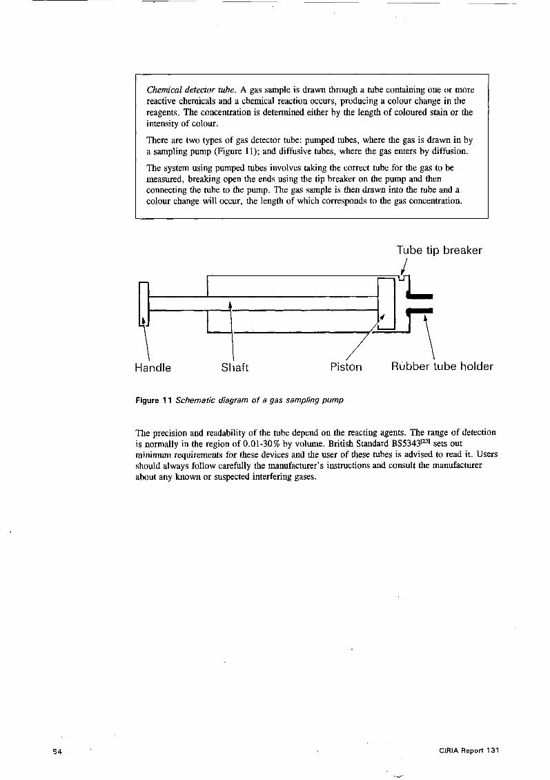
Chemical detector tube. A gas sample is drawn through a tube containing one or more reactive chemicals and a chemical reaction occurs, producing a colour change in the reagents. The concentration is determined either by the length of coloured stain or the intensity of colour.
There are two types of gas detector tube: pumped tubes, where the gas is drawn in by a sampling pump (Figure 11); and diffusive tubes, where the gas enters by diffusion.
The system using pumped tubes involves taking the correct tube for the gas to be measured, breaking open the ends using the tip breaker on the pump and then connecting the tube to the pump. The gas sample is then drawn into the tube and a colour change will occur, the length of which corresponds to the gas concentration.
Tube tip breaker
J
Handle s1;art Piston Rubber tube holder
Figure 11 Schematic diagram of a gas sampling pump
The precision and readability of the tube depend on the reacting agents. The range of detection is normally in the region of 0.01-30% by volume. British Standard BS5343IB1 sets out minimm requirements for these devices and the user of these tubes is advised to read it. Users should always follow carefully the manufacturer’s instructions and consult the manufacturer about any known or suspected interfering gases.
54 ClRlA Report 131
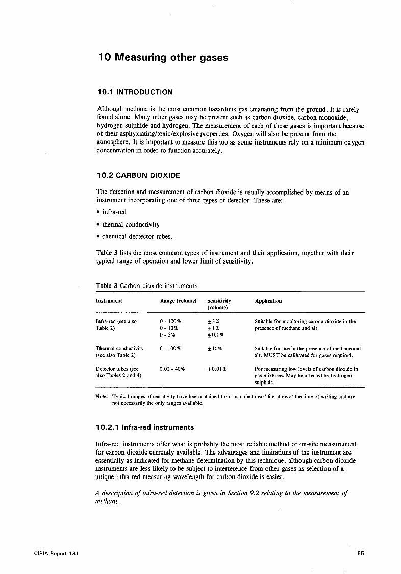
10 Measuring other gases
10.1 INTRODUCTION
Although methane is the most common hazardous gas emanating from the ground, it is rarely found alone. Many other gases may be present such as carbon dioxide, carbon monoxide, hydrogen sulphide and hydrogen. The measurement of each of these gases is important because of their asphyxiating/toxic/explosive properties. Oxygen will also be present from the atmosphere. It is important to measure this too as some instruments rely on a minimum oxygen concentration in order to function accurately.
10.2 CARBON DIOXIDE
The detection and measurement of carbon dioxide is usually accomplished by means of an instrument incorporating one of three types of detector. These are:
infra-red
thermal conductivity
chemical dectector tubes.
Table 3 lists the most common types of instrument and their application, together with their typical range of operation and lower limit of sensitivity.
Table 3 Carbon dioxide instruments
Instrument Range (volume) Sensitivity Application Ivolume)
Infra-red (see also 0 - 100% *3% Suitable for monitoring carbon dioxide in the Table 2) 0 - 10% * I % presence of methane and air.
0 - 5 % *O.I%
Thermal conductivity 0 - 100% f 10% (see also Table 2)
Detector tubes (see 0.01 - 40% f0.01 % also Tables 2 and 4)
Suitable for use in the presence of methane and air. MUST be calibrated for gases required.
For measuring low levels of carbon dioxide in gas mixtures. May be affected by hydrogen sulphide.
Note: Typical ranges of sensitivity have been obtained from manufacturers’ literature at the time of writing and are not necessarily the only ranges available.
10.2.1 Infra-red instruments
Infra-red instruments offer what is probably the most reliable method of on-site measurement for carbon dioxide currently available. The advantages and limitations of the instrument are essentially as indicated for methane determination by this technique, although carbon dioxide instruments are less likely to be subject to interference from other gases as selection of a unique infra-red measuring wavelength for carbon dioxide is easier.
ClRlA Report 131
A description of infra-red detection is given in Section 9.2 relating to the measurement of methane.
55

An instrument based on infra-red measurement has the following advantages:
1. The detection method does not consume any component of the sample, thus allowing options such as recirculation of the sample (Section 12.3) to be used even on small volumes of material.
This is very useful when the amount of sample is limited. By recirculating it through the analyser more accurate measurements may be obtained.
2. The sampling cell can be made small enough to fit insitu in the sampling point so that measurements can be made without physically removing the sample.
3. The detection system can be made essentially specific to carbon dioxide.
4. The output from many sensors can be linked to form a network to provide continuous long-term monitoring.
5. The sensor cannot be poisoned.
6 . A single instrument with detectors operating at different infra-red wavelengths can be used to measure both carbon dioxide and methane simultaneously.
The disadvantages of the infra-red sensor for the measurement of carbon dioxide are:
1. The presence of water in the gas, particularly if it condenses in the sample cell, will affect the readings.
Water has a very broad band of absorption in the infra-red region of the spectrum. The infra-red radiation Will also be absorbed by any water present in the gas particularly if allowed to condense within the sampling cell. This is usually overcome by heating the sampling cell to prevent condensation forming.
2. A dirty sampling cell can cause the instrument to under-read.
Dirt on the windows of the detector cell can cause the signal given for a particular concentration to decrease, thereby registering a lower concentration than the true value.
10.2.2 Thermal conductivity instruments
Because many gases have a unique thermal conductivity, instruments based on a thermal conductivity sensor can be manufactured to determine the concentration of a wide variety of single gases (e.g. carbon dioxide) in air (or other reference gas). But since the sensor only measures the difference in thermal conductivity between the reference gas and the sampled gas, the presence of multiple components in the mixture can seriously affect the readings. This can be overcome by using one of two techniques:
1. To remove component gases.
For simple mixtures containing no more than three major components (e.g. methane and carbon dioxide in air) it is possible to take a combined measurement on the whole sample, and then a second measurement with one of the gases removed (e.g. carbon dioxide removed on a suitablefilter), and by calculation determine the true concentration of both the methane and the carbon dioxide in the original sample. l l i s method is not recommended for site work as it leaves too much room for error.
ClRlA Report 131 <
. .
. . ' .

2. Use of gas chromatography.
For very complex mixtures gas chromatography can be used to separate the individual components in a mixture, and each one can then be determined separately with a single detector calibrated for each component.
The principal drawbacks of instruments which are based solely on this type of sensor arise from their non-specificity which can lead to erroneous readings under quite common conditions.
For a more detailed description of the thermal conductivity sensor see Section 9.4 on methane detection using combined catalytidthermal conductivity detectors.
10.2.3 Chemical detector tubes
The chemical detector tube (described in Section 9.7) can also be used to determine carbon dioxide. A gas sample is drawn through a tube containing one or more reactive chemicals and a chemical reaction between the gas or vapour being sampled occurs producing a colour change in the reagents. The concentration is determined either by the length of coloured stain or the depth of colour.
10.3 OXYGEN
There are three main types of detector used to monitor oxygen (see Table 4). These are:
electrochemical cells
paramagnetic cells
detector tubes.
Table 4 Oxygen instruments
Instrument Ranee (volume) Sensitivity A~olication
Electrochemical cell 0 - 100% * O S % Monitoring oxygen content in gas mixtures, e.g. 0 - 25% landfill gas.
Paramagnetic cell 0 - 100% *2 .5% Monitoring oxygen content in gas mixtures. Mainly used in process control.
Detector tubes 2 - 24% *2.0% In areas where flammable gas present. May be effected by other gases, e.g. Hydrogen sulphide.
Note: Typical ranges of sensitivity have been obtained from manufacturers’ literature at the time of writing and are not necessarily the only ranges available.
10.3.1 Electrochemical cells
Most commonly used for the determination of oxygen, instruments based on electrochemical cell sensors are available for a wide range of gases and can be used to determine the presence of carbon dioxide, hydrogen sulphide, and carbon monoxide.
They can be supplied as individual instruments or are sometimes combined within other gas detectors to provide a means of measuring the oxygen concentration and ensuring it is adequate for the detector to function.
The disadvantages with this type of sensor are:
ClRlA Report 131
1. The electrolyte is used up during the reaction and hence the cell has a limited life span.
57

Electrochemical cell. The basic electrochemical device consists of two electrodes in an insulated container, fitted with a membrane that is permeable to the gas being sampled but that will retain the electrolyte (usually in the form of a gel) in the cell. With a potential applied across the cell and gas diffusing through the membrane into the electrolyte a chemical reaction takes place, producing a current which increases with the concentration of gas present.
By careful design and choice of electrolyte these sensors can be made very specific to a single gas. Because the process is controlled by diffusion of gas through the membrane some temperature dependence of the measurement may be observed, although this can be compensated for electronically or by other modifications in the design.
2. They can be poisoned by certain gases.
10.3.2 Paramagnetic instruments
Apart from the instruments based on electrochemical cells, the most commonly used instruments for measurement of oxygen are ‘paramagnetic’ analysers. These effectively detect the partial pressure of oxygen present in the sampled atmosphere by withdrawing a sample into the instrument from which a direct reading of the concentration is obtained.
Paramagnetic instruments. The detection of oxygen with paramagnetic sensors relies on oxygen’s property of positive magnetic susceptibility, i.e. it causes a greater concentration of magnetic force within itself than in the surrounding magnetic field - a phenomenon known as paramagnetism. All other common gases (except nitric oxide) have a negative magnetic susceptibility. By measuring this property or changes derived from it, the concentration (or more strictly the partial pressure) of oxygen can be determined.
Three types of paramagnetic instrument commonly exist: magnetic wind instruments, Qwinke analysers and Pauling’s dumb-bell cells. The detailed operation of these individual types of sensor is quite complex and can be found in detail in Cooper( 1987)[?
L
The principal advantage of these instruments is that they are not subject to interference from any other commonly encountered gas, as oxygen is almost the only one which is paramagnetic.
A drawback in the use of these instruments is that most of them actually respond to changes in partial pressure of oxygen and not concentration directly. This means that the reading will fluctuate with changes in atmospheric pressure and, where instruments are calibrated for simplicity to read in percentage oxygen, under some conditions serious error may result. For many applications this is not critical, but for accurate measurements it is important to adjust all partial pressure instruments, however calibrated, to take account of barometric pressure.
Both paramagnetic and electrochemical instruments will normally provide a sufficiently accurate indication of the oxygen concentration for most situations.
10.3.3 Davy lamp
This device has been widely used to indicate oxygen deficiency for many years. It cannot be truly described as an instrument as it has no output meter or digital indication, nor can it give an alarm signal in the accepted sense. The extinguishment of the lamp is usually taken to indicate a hazard and this occurs at around 15.9-16.6% oxygen. Although not expected to have wide use it may still serve to check atmospheres before entry into tunnels and sewers.
a .
58 I. .
ClRlA Report 131 > .’I

10.4 HYDROGEN SULPHIDE, CARBON MONOXIDE AND HYDROGEN
10.4.1 Hydrogen sulphide
Electrochem’cal cell. This type of detector uses a wide range of detector cells to monitor different gases. Inorganic gases such as hydrogen sulphide are measured using a coulometric cell. The gas reacts within the cell creating a current which is proportional to the amount dissolved. A measurement is then made of the number of coulombs of current produced.
Detector tubes. These consist of a chemical reagent adsorbed on to an inert support within a glass tube. When air is drawn into the tube the concentration of a particular contaminant will be recorded by the length of the stain in the reagent. Selectivity is achieved by using a reagent that only reacts with the particular contaminant to be measured. For hydrogen sulphide the reagent commonly used is lead acetate, which produces a brown stain.
Test paper. Similar to detector tubes, test papers provide another means of on-the-spot analysis. They are impregnated with a reagent specific to the gas of interest. A chemical stain is produced, on exposure to the gas, of an intensity which is proportional to the gas concentration.
These devices are often used as personal monitors.
The above techniques are the most common, but there are also instruments that use the following sensors.
Semiconductor sensor. These devices rely on the adsorption of the hydrogen sulphide gas on to a heated oxide surface. The subsequent reaction on the surface of the oxide produces an electrical conduction change in the oxide which is related to the amount of gas adsorbed.
Photoionisation. In this type of analyser the hydrogen sulphide gas molecules are subjected to an ultraviolet light source which leads to the ionisation of the molecules. The ions are then drawn to a collector electrode which creates a current proportional to the concentration measured.
10.4.2 Carbon monoxide
The most popular detection method is the electrochemical cell. Other techniques used are: semiconductors, detector tubes, thermal conductivity, and infra-red.
10.4.3 Hydrogen
The most popular detector types for hydrogen are catalytic and thermal conductivity devices. Also used are electrochemical cells, semiconductors and detector tubes.
10.5 MULTIPLE GAS DETECTION
10.5.1 Portable analysis kits
ClRlA Report 131
As well as single instruments capable of performing multiple-component analysis, it is also possible to purchase portable analysis kits which will enable multiple components to be measured. These kits consist of two or more different types of detector, either as separate entities with individual sampling inputs or as a single sample input which is connected to each detector. A typical combination of detectors would include a catalytic detector for flammable gases, a thermal conductivity detector for toxic inorganic gases and an electrochemical cell device for oxygen determinations.
59

10.5.2 Portable gas chromatographs
Until recently the use of gas chromatographs has been limited to off-site analysis, but now portable instruments are available, making on-site identification of the components of landfill gas possible. The main features of these instruments are:
small and of low weight (about 5kg)
fast run times
sensitivity (minimum detectable concentration of lppm)
half the price of a conventional laboratory-based machine.
Their main disadvantage is that they are of lower resolving power than their laboratory-based counterparts, being able to identify only 30-40 compounds.
‘I
10.6 SUMMARY
Once users have decided on the requirements for gas detection instruments, they can then examine a wide variety of different types and make a choice as to which will suit their needs. Each one will have its own advantages and disadvantages. Some sensor types such as catalytic oxidation and flame ionisation are specific to a particular type of gas (flammable); others, such as electrochemical cells and detector tubes, can be used to detect a number of different gases, e.g. oxygen, hydrogen sulphide and carbon monoxide.
The presence or absence of certain gases may also have an effect on the sensor accuracy, and hence the conditions under which a sensor is to be used must be borne in mind when choosing an instrument utilising a particular sensor. Many devices are now available which attempt to overcome this problem by incorporating two or more different sensors within one instrument. This enables the user to check the concentrations of gases that may affect the readings of the gas of particular interest.
60 ClRlA Report 131
I .

I 1 Gas sampling points
1 1 .l Introduction
i
If reliable representative results are to be obtained from a site investigation attention must be paid to the design of sampling points and sampling methods. It may be very difficult, if not impossible, to obtain a truly representative gas sample, since most methods for sampling inevitably involve some disturbance of the ground. This fact must be recognised and suitable steps taken to minimise the problem whenever practical. Each of the methods of sample point construction described below should be considered as complementary techniques which will be appropriate for use in combination as well as individually, in appropriate circumstances.
1 1.2 TEMPORARY SAMPLING POINTS
In the initial stages of an investigation it is advantageous to take measurements quickly over a wide area. To achieve this, simple probing of the ground by spiking or the use of temporary shallow probes can quickly yield useful information.
1 1.2.1 Simple spiking
This is a quick and easy method of taking a gas measurement. A metal spike is forced into the grouiid and then pulled out. The tube from the gas detection instrument is then placed into the hole and a gas sample drawn into the device for measurement.
The disadvantages of this technique are:
1. Gas measurements will not be highly accurate due to the possibility of air ingress to the hole.
2. Loose earth or water may clog the gas sample line.
3. The depth to which sampling is possible is limited to 1-2m.
11.2.2 Shallow probes
Another simple method of probing for gas in the first stage of an investigation in soils and refuse is to sink a small hollow rigid pipe into the ground, to a depth of about lm, with a tube connection to a gas detection device (Figures 12 and 13). The probe itself may be hammered directly into the ground or a pilot hole made with a length of steel rod prior to inserting the probe.
One type (Figure 14) found to be particularly good consists of a lm long 25mm diameter steel tube pointed at one end. The lower half of the tube is perforated at 45mm intervals with 4mm holes countersunk by 2mm, intended to prevent clogging by soil. After inserting the probe the hole is sealed at the surface to minimise the ingress of air, and samples may be withdrawn immediately thereafter from a sampling outlet near the head.
The effectiveness of this technique is very dependent on cover thickness and permeability. Gas concentrations comparable to those from deeper probes can only be measured on sites with thin or permeable covers.
The benefits of shallow probing are:
1. The equipment can be cheaply and easily supplied.
ClRlA Report 131 61

25mm
I I Diameter 6mm
7 -
2 05rn
0
0
0
Figure 12 Diagram of apparatus for sampling landfill gases
Sampling
Figure 13 Soil gas probe (Research Engineers L tdl representative of the type used by Flower
tube (a lum I niu m) I
22 No. 4mrn Q holes countersunk to a depth of 2rnm
1 -
10 No. pitches at 45rntn - 450rnni
1
End detail machined to a tight fit and welded into position
- End detail machined to a tight fit and welded into position 4rnm Q x 20mm long tub
welded into position
- Steel tube 25mrn Q x 1115rnrn long heavy gauge to B S 3601 heavy gauge
Figure 14 Shallow spiking probe
62
. . .
" ClRlA Report 131

2. It does not require specialist operators.
3. Very little site disturbance is involved.
4. The technique is quick to use and has no major safety implications.
The problems encountered when using this technique are:
1. Air diffusion can reduce the measured gas concentrations.
2. The small sample volume can give misleading results.
~ 3. No visual assessment or sampling of fill materials can be made.
4. Probes are easily blocked by debris and water.
5. There is a danger of over-pumping.
When using narrow bore-tubes there is a possibility of over-pumping which can result in air being drawn in from the sulface, thus diluting the gas sample. It is particularly important to eliminate this when sampling tubes are being used to take samples for laboratory analysis.
11 .3 PERMANENT AND SEMI-PERMANENT SAMPLING POINTS
For subsequent stages of a site investigation permanent or semi-permanent sampling points will have to be installed. A regular grid is often the best initial arrangement although no hard and fast rules on the size of the grid exist. A large number of sampling points will not necessarily give a clearer picture of the conditions on site, but, interpretation and interpolation of results obtained on too coarse a grid will be difficult. As a starting point, the grid locations should not be greater than 60 m and probably do not need to be closer than 30 m.
Permanent sampling points should not be left open. An open sampling point may:
allow air into the ground thus reducing locally any anaerobic activity
allow the release of large amounts toxic and flammable gases
slow down equilibration of the sampling point with the surrounding ground
dilute the ground gases, resulting in inaccurate concentration measurements.
In addition, to prevent tampering by vandals, the top of the sampling point should be protected as far as possible with some form of vandal-proof cover.
For ease of sampling it is advisable to have an inlet and an outlet probe permanently fixed at each point. Each should be fitted with an isolating valve which can be used to seal the sampling point between measurements.
Sealing the sampling point will assist its equilibrium with the surrounding ground conditions.
There are a number of techniques available for the construction of permanent.sampling points. These should be considered as complementary rather than independent as each will have an application in most site investigations.
11.3.1 Shallow probes
ClRlA Report 131
If correctly constructed and protected, simple shallow probes can be used as semi-permanent sampling points for repeated measurements. A simple construction is shown in Figure 15 in which a hole is drilled and the fixed sampling point is fitted.
63

compacted
150 mm - 200 mm plastic tube
1
, Hole formed with metal bar or small (1 3 mm - 25 mm) drill
Figure 15 Shallow probe sampling point
11.3.2 Deep driven probes
Sampling probes may be installed to depths of about 10m by a compressor-driven hammer impacting on a collar which grips a hollow steel tube approximately 50mm in diameter with a hardened, solid nose-cone (which is subsequently left in the ground on extraction of the main probe). The hammer action drives the probe into the ground a short distance with each blow. Extension tubes can be fitted as necessary to allow the probe to be driven to the required depth.
The hammer may be used to install a perforated probe directly, or the driving probe may be a hollow tube into which a smaller 35mm diameter perforated pipe can be inserted after installation, and pneumatic jacks used to remove the outer steel casing, leaving the monitoring pipe in place (Figure 16). On extraction of the casing, surrounding soil and wastes are allowed to collapse onto the pipe and a protective section with a threaded cap is then attached which can be concreted in position for security.
As well as hammer-driven probes, a new technique has recently been developed from apparatus used for reinforcing earth slopes, i.e. soil nailing, where explosively driven probes are used. Whilst this allows probes to be driven deep into the ground, it requires the use of specialist equipment and operators.
A stabilisationperiod for the sampling point of up to three weeks may be required for some installations, although reliable data can sometimes be obtained after only a few days, as there is usually relatively little ground disturbance.
64 ClRlA Report 131

t F
I I I I I I 
5 . There is no visual indication of the groundmass penetrated, although the ease or difficulty of driving may provide some indication of the materials.
11.4 BOREHOLES
A permanent or longer-term monitoring point will usually need a hole drilled into the ground. This may be lined with a perforated pipe made of a material that will not adsorb the gases (UPVC is sometimes used), or left unlined and sampling probes installed directly.
Designs for the arrangement of probes within the hole vary, but generally the gas probe is inserted to the required depth and void spaces are backfilled with pea gravel or similar open- pored material. The top of the hole is sealed to prevent ingress of air and to protect personnel from any toxic gases emanating from the borehole. A number of different arrangements are illustrated in Figures 17-21.
Stopcock box or similar set in concrete
PVC cap drilled for 5mm O.D. tubing
Concrete or cernenffBentonite
w lOOmm or greater
E E 0 0 m
3mm ID. tubing
3mm O.D. copper tubing
rubber stopper
13mm PVC pipe
3mm diameter holes throu pipe at 25mm spacings
' rubber stopper
Figure 17 Typical borehole installation Figure 18 Typical gas probe tip in borehole ins talla tion
The perforated portion of a probe or lined section of a hole may extend down the full depth of the hole, apart from say 1 m from the surface, or may be a short section at the base of the .hole. A number of samples should be withdrawn from different depths inside the hole to account for any variations in concentration that might occur with depth.
.
.
As an alternative to using a single probe to sample from different depths within a borehole, more than one probe[28p311 may be installed (see Figure 19) at different depths in the same hole. Multiple installations on a single stem using packers or grout seals[29], such as shown in Figure 20, provide a practical method which avoids the difficulties of depth control and backtilling around two or more pipes. In these arrangements lengths of the borehole between the zones being monitored must be sealed to prevent gas migration from one zone to another. These
66 ClRlA Report 131
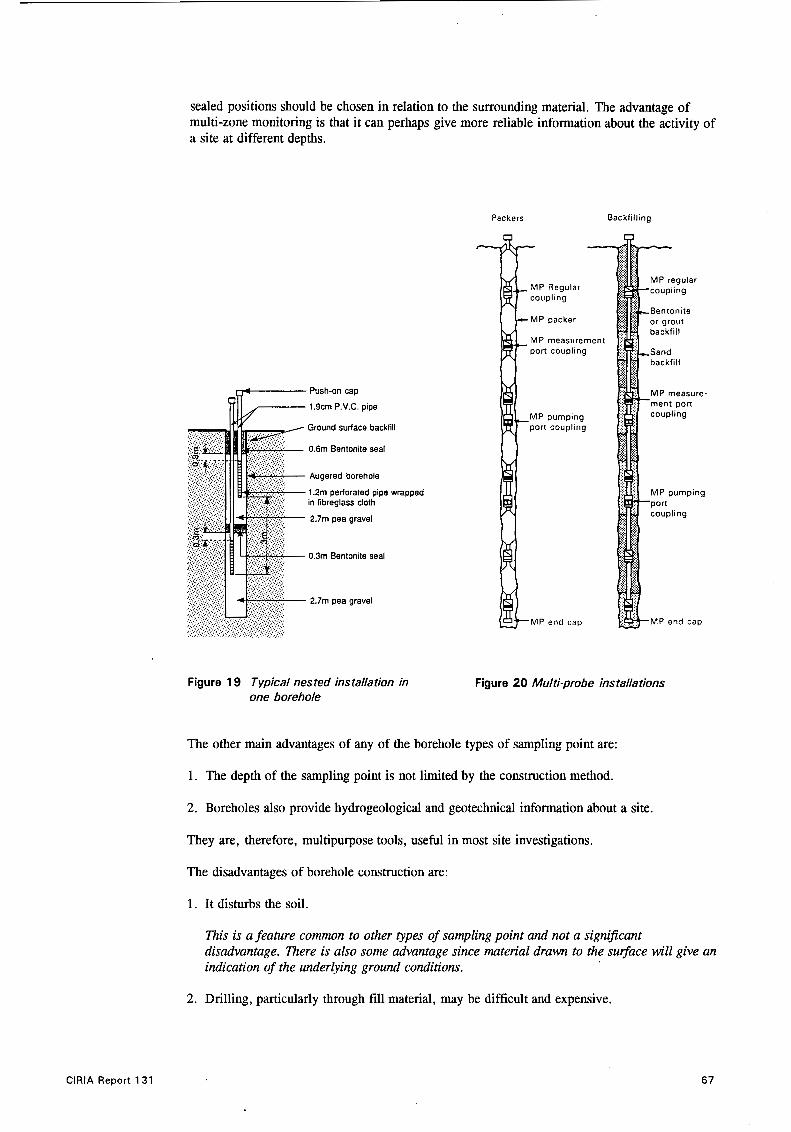
sealed positions should be chosen in relation to the surrounding material. The advantage of multi-zone monitoring is that it can perhaps give more reliable information about the activity of a site at different depths.
Backfilling Packers
Push-on cap
1.9cm P.V.C. pipe
Ground surface backlill
0.6m Bentonite seal
Augered borehole
1.2m perforated pipe wrapped in fibreglass cloth
2.7m pea gravel
0.3m Bentonite seal
2.7m pea gravel
. . .
Figure 19 Typical nested installation in one borehole
-
MP measurement
MP measure-
Figure 20 Multi-probe installations
The other main advantages of any of the borehole types of sampling point are:
1. The depth of the sampling point is not limited by the construction method.
2 . Boreholes also provide hydrogeological and geotechnical information about a site.
They are, therefore, multipurpose tools, useful in most site investigations.
The disadvantages of borehole construction are:
1. It disturbs the soil.
This is a feature common to other types of sampling point and not a signijicant disadvantage. There is also some advantage since material drawn to the sugace will give an indication of the underlying ground conditions.
2 . Drilling, particularly through fill material, may be difficult and expensive.
ClRlA Report 131 67

3. They can usually be excavated and backfilled quickly.
Trial pits are, therefore, particularly useful in a preliminary investigation of the site for detecting gas and other types of contamination.
Provided adequate safety precautions are taken, a crude method of determining the presence of gas before backfilling is to cover the trial pit overnight with a plastic sheet or tarpaulin. Samples of the atmosphere under the sheet can then be taken to find out if flammable or harmful gases are present.
Precautions must be taken to ensure that personnel do not enter a pit. Staff should be forbidden to do so. In addition, as a general rule, personal monitoring devices should be worn by people working on the pits. Similarly, the potential for an ignition to occur within a pit should be minimised by the use of ‘safe’ equipment and, where necessary, the removal of smoking material from working personnel.
The principal disadvantages of the trial pit as a sampling point are:
1. The limitation of the depth that can be examined.
2. The considerable disturbance of the soil created by digging the pit.
3. The possible formation of air pockets on backfilling.
4. Odours from the pit may create a public nuisance and environmental health hazard.
Because of the substantial soil disturbance, a longer period will be needed before ground conditions return to normal and measurements can be made. Both these factors may place some limitations on the use of trial pits. However, the ease of construction, the additional benefit of a visual examination of sub-surface conditions, the possible benefit of allowing a route for the gas to escape, ease of detection and the cost advantages make trial pits a satisfactory addition to boreholes. This is particularly so for the initial stages of an investigation or on sites with a relatively shallow depth of fill.
11.6 SURFACE SAMPLING APPARATUS
As an alternative to the use of sub-surface sampling methods, although probably not widely used, attempts have been made to characterise gas emission from collection points situated on the surface. The procedure is to invert a large open container over a small area of the site so that the gas emanating from the surface can be collected inside. Measurements are obtained either by grab sampling or continuous monitoring of the internal atmosphere with a suitable instrument. The container, typically a plastic water tank or steel drum, is sealed at the ground surface with a material such as bentonite and should have some form of pressure relief system to avoid pressurising the container. An example of this type of apparatus is shown in Figure 23.
11.7 SUMMARY
Various designs of sub-surface sampling points are in use, ranging from the simple spiking of the ground to form a hole from which a gas sample is taken, to the use of more expensive boreholes and trial pits. Each method has its own limitations many of which can be overcome by using a combination of techniques. The choice of sampling point will, to a large extent, be determined by the site conditions and will also depend on whether information is required about the sub-surface materials and groundwater.
Surface sampling of gases can be undertaken by either collecting the gas inside a container such as a plastic water tank or steel drum, or by taking direct measurements using a
70 ClRlA Report 131

ClRlA Report 131
. . . ..
flame-ionisation detector. Surface sampling, if used at all, should not be undertaken without sub-surface sampling.
L Jk-
Figure 23 Surface sampling
71

12 Sample collection
12.1 INTRODUCTION
Obtaining a representative sample of gas from a sampling point is as important as the instrumentation used and the sampling point construction. The procedures for determining composition and concentration of gas samples are relatively easy providing simple precautions are taken and the limitations of the measuring instrument are understood.
12.2 GROUNDWATER LEVEL
Before any sampling is attempted it is advisable to determine the water table level, so that sample lines/probes are not placed too deeply resulting in water being sucked into the instruments or collection vessels. It may often be worthwhile installing a simple water trap (Figure 24) to prevent water accidentally getting into an analyser. This does however have the disadvantage of increasing the sampling system volume.
Butterfly valve
PVC pipework -.
A-
1 Inlet
High density ’ polyethylene drum
Figure 24 Gas dewatering drum
12.3 SAMPLE SYSTEM - ON SITE MEASUREMENT
On site, the simplest procedure is to connect the measuring instrument to the sample point and withdraw samples until a steady reading is obtained. To minimise the influence that withdrawing the sample from the sampling point has on the measurement itself, ideally the volume from which the sample is being taken should be as large as possible, while the volume of the sampling system (probes, sampling lines and other external apparatus) should be as small as possible. Sampling lines should not be so narrow, however, that they restrict the gas flow.
If determining more than one component with different instruments this procedure will have to be repeated for each gas. Alternatively, the analysers may be connected to the sample point in parallel (Figure 25) and measurements made simultaneously. It is advisable to fit non-return
72 ClRlA Report 131

valves on the inlet to each analyser to prevent air being drawn back through them by the other instruments. If an external pump is available, care should be taken to ensure that the pump neither draws in air nor over-pressurises the analysing equipment.
Non-return valve
Sample point
Sample line
Figure 25 Schematic of parallel sampling s ystem
Normally the analysed gas sample would be vented into the atmosphere, but an alternative procedure is to recirculate it back into the borehole or standpipe. Providing the volume of the sample lines is small relative to that of the sampling point, the steady state reading obtained will be close to the equilibrated concentration in the ground. The off-take and reinjection points should be as far apart as possible to ensure maximum circulation within the sampling point (Figure 26). This method has some advantages in that it reduces the possibility of air being drawn into the ground as a result of the sampling procedure, but it cannot be employed when using instruments that destroy the sample in measurement.
It may often be the case that the amount of sample available for measurement will be physically limited by the dimensions of the sampling point and other factors such as high water table levels and low rates of replenishment. Under these circumstances reasonable readings may be obtained if the recirculation method is used. Alternatively an in-situ sensor may be used, but again this should be of a type which does not destroy the sample.
12.4 SAMPLE COLLECTION FOR OFF-SITE ANALYSIS
The removal of samples for off-site analysis can be done in a variety of ways. The choice of method is to some extent arbitrary, but some types of subsequent analysis, particularly if aimed at determining the minor components in a mixture, are facilitated by certain special methods.
It must be remembered that when samples are collected for analysis a reduction in the concentration of gas on the site may result. Hence it is advisable to collect as small a sample as possible, especially on sites emitting small volumes of gas.
ClRlA Report 131 73

Gas from analyser Gas to analyser
Figure 26 Recirculation of gas from a sampling point
A simple and widely used method of collecting gas samples for analysis is to use pressurised sampling cylinders (GreshamF) Tubes see Figure 27). These are designed to be used with a hand pump to compress the gas sample into a small cylinder made from either aluminium alloy or preferably stainless steel. Various types of cylinder are available: ‘flow through’ (i.e. with a valve at each end of the tube) to allow pre-purging with the sample gas, or ‘closed end’ which should be filled and emptied several times to ensure a representative sample is obtained. They are available in various sizes from 15 ml up to 110 ml.
L
Figure 27 (a) Gas sampling cylinder (single headed) lb) Gas sampling pump (two stage)
Another simple arrangement (Figure 28) for obtaining a sample consists of a gas sampling vessel, which may be sealed at both ends by taps or valves. The vessel is connected to the sample point in series with a vacuum pump or hand aspirator to provide suction. A by-pass line may also be fitted, if desired, to allow monitoring of the sample to proceed while the sampling vessel is being removed. Gas is withdrawn by the pump through the sampling vessel until at least three to five volume changes of the vessel have been carried out. If, as is advisable, some continuous monitoring is being performed, the vessel should be flushed until a steady reading is obtained at its outlet. Having filled the vessel, the taps are closed, and it is removed.
74 f ClRlA Report 131

r .
Removable sample vessel with iso la t ing valves or taps
To pump 1 Figure 20 Principle of a simple collection system
It is important that for both these methods the sample should be clearly labelled. Labelling should include: date, time, location and, whenever possible, the approximate concentration of at least one major component.
It may also be advisable with these methods to flush the sample tube with an inert gas such as argon before use. This will ensure that, if the tube is not thoroughly flushed with sample gases during the sampling process, their true concentration can be calculated by determining the amount of residual argon.
The sampling vessel can be pre-filled with a liquid as an alternative method of providing suction to withdraw the sample if no a pump is available. Emptying the liquid from the vessel under gravity provides suction to fill it from the sampling point. The liquid used should be acidified distilled water, with added methyl red indicator, since the low pH minimises the dissolving of carbon dioxide in water.
A comparison of these two methods of filling a sampling vessel showed the sampling technique had no effect on the results, although the pumping system was found to be easier to US^^].
A further alternative to the straightforward sampling vessel is to use a pre-evacuated vessel into which a sample can be withdrawn directly from the sampling line. A possible advantage of this technique is that it reduces the total volume of gas removed from the site, thereby minimising the potential for air ingress due to sampling procedure.
12.5 MATERIALS
12.5.1 Tubing
It has already been mentioned that the volume of sampling lines should be kept to a minimum and short narrow lengths of tubing used wherever possible. Care must be taken to ensure that the tubing is not so narrow as to restrict the gas flow or become easily clogged by water or debris which may accidentally be withdrawn with the gas.
ClRlA Report 131
The tubing used needs to be robust and flexible, although the ideal material for fixed parts of an installation is internally clean stainless steel. For the determination of the major gas
75

components the choice of materials is probably not critical since other factors are likely to have a much more significant effect on the measurements made. Any general purpose flexible tube may be used although the best materials are probably neoprene, polypropylene or Tygonw).
For the measurement of low concentrations of gas and trace components the adsorption and desorption properties of the tubing can be important. If collecting samples for detailed laboratory analysis the use of an inert flexible tubing such as Vitofl) is preferable.
12.5.2 Drying agents
The use of drying agents to remove water vapour from the gas sample is desirable to minimise the risk of damaging the equipment and to ensure reliable measurement if using instruments that are sensitive to moisture.
Large amounts of water and other condensates should be collected in a water trap, but drying agents will be required to remove residual amounts of water vapour. Care over the choice of agent should be taken since some agents, particularly silica gel, will absorb gases such as carbon dioxide. This problem is exacerbated as the agent becomes wet. For some infra-red analysers the recommended drying agents for other than the most sensitive analysis are either anhydrous calcium chloride or anhydrous calcium sulphate. For sensitive analysis magnesium perchlorate is probably the most suitable drying agent.
12.5.3 Sampling vessels for sample collection
A sample collection vessel may be made of glass although for site investigations metal vessels would prove more durable. Ideally, these should be made from stainless steel, though brass or monel may be suitable for most purposes where the gas is not corrosive.
12.6 SAMPLING BY ADSORBENT MEDIA
The methods described above for sample collection are generally applicable, but where detailed analysis of minor components is required more specialised techniques may have to be employed. These utilise adsorbent columns or cold traps which selectively trap, and therefore concentrate, particular groups of compounds. These are specialised techniques which require a relatively high degree of expertise.
Sample tubes made of glass and containing a high-activity sorbent can be used to collect gases from air samples. A sample is collected by breaking off the end tips of the tube and drawing the aidgas sample through. The chemical is adsorbed onto the sorbent in the tube and push-on caps fitted to seal the ends. It can then be taken to a laboratory where the trapped chemicals are solvent-extracted or thermally desorbed before being analysed by gas chromatography.
This method of sample collection is not widely used to collect gas samples emanating from the ground.
12.7 SUMMARY
There are basically two ways of approaching the task of collecting and analysing a gas sample from a gassing site. One method involves withdrawing a sample from a sampling point directly into a measuring instrument, to give an on-the-spot reading. Alternatively, a sample can be collected and taken to a laboratory for a more detailed analysis. Various methods of sample collection can be used; the most common involve pumping the gas into a cylinder or vessel. A less popular technique uses adsorbent media to collect the gas sample, which is then desorbed in the laboratory.
Care should be taken when choosing the materials to be used for the tubing and drying agents, as adsorption of some of the constituent gases in the sample may occur.
ClRlA Report 131

13 Meteorological data
13.1 METEOROLOGICAL EFFECTS
It is important during the monitoring of a site for gas emission that the climatic conditions prevailing before and at the time are recorded. The information obtained from these records may help in the interpretation of the gas monitoring data and explain any anomalies. Measurements should be taken on-site and backed-up by data from the Meteorological Office.
The four parameters generally recorded are:
temperature
atmospheric pressure
rainfall
wind speed/direction.
13.1.1 Temperature
No clear relationships have been found to exist between temperature variations and gas concentrations or gas emission rates, though in shallow landfill sites high air temperatures may encourage increased landfill gas generation, the optimum temperature range being 35" to 45°C. If the ground becomes frozen the surface of the site will effectively be sealed, inhibiting gas evolution, but causing the gas to increase its lateral migration.
13.1.2 Atmospheric pressurehainfall
Gas concentrations do not appear to be influenced at all by variations in atmospheric pressurehainfall. Gas flow rates, however, can be affected. On some sites a fall in atmospheric pressure can lead to a higher gas emission rate from the ground, although this relationship is not totally clear and depends on whether the area of influence extends over the site and surrounding strata, or just the surrounding strata. Another variable that determines the rate of emission of gas from a site is the rate of change of atmospheric pressure: a rapid fall will increase the rate of emission. Not all gas flow rates are affected in this way, the effects of atmospheric pressurehainfall are generally site specific.
Over periods of prolonged dry weather, site-covering material, especially if formed of clay, will tend to crack, causing increased gas emission from the site. In wet weather rainfall percolating downwards can close up gas pathways.
Gas migration can also be affected by barometric pressure and rainfall in the following ways:
by creating pressure gradients
Low atmospheric pressure creates a favourable pressure difserential for the gas to migrate from its source to the surface.
by increasing lateral migration
Rainfall tends to seal the surface of the ground, temporarily encouraging the gas to migrate further than it otherwise might.
4
by increasing gas emission.
Rainfall can alter the water table. A rising water table can pressurise the gas and force it out, possibly cutting ofsprevious migration routes. Conversely, a rapidly falling water table m y draw air into the ground.
ClRlA Report 131 77

13.1.3 Other effects
On sites such as in-filled docks there are significant tidal effects which alter the gas emission patterns. When the tide is in the water table will rise, forcing the gas out at a greater rate than when the tide is out. Wind speed and direction can make gas emission readings difficult to take, particularly when using hot-wire anemometers.
13.2 SUMMARY
Climatic influences on the gas regime on a site should not be underestimated when taking gas measurements. Changes in temperature, atmospheric pressure, rainfall, wind speedldirection and tidal effects can all influence the gas readings. It is therefore important that these parameters are recorded along with the gas measurements, and their effects on the gas noted if the collected data are to be interpreted correctly.
78 ClRlA Report 131

14 Methane in groundwater
14.1 INTRODUCTION
Methane which is dissolved in groundwater under pressure may be released into the atmosphere when pressure is relieved. This can occur if the water reaches the surface, or if the groundwater is penetrated by a low-pressure construction such as a pipeline, tunnel or mine. Such gas releases may represent a hazard directly by entering the construction, or indirectly as a result of water or gas tracking along the direction of the tunnel and being released where it breaks the surface. It is therefore important, when involved in underground construction, that the groundwater is assessed for dissolved methane and other gases.
14.2 SAMPLE COLLECTION
In order to collect good groundwater samples for dissolved gas analysis it is important that the design of the sampler should meet certain criteria[”].
It should not allow sample concentration changes, which could arise from:
changes in temperature or pressure
leaching from the sampler
contamination or sample loss during handling.
The sampler should also have the following attributes:
be able to collect samples reproducibly
be easy to use
be inexpensive
be used in a variety of wellshoreholes at varying depths.
For dissolved gases such as methane, the presence of a headspace volume in the sampling apparatus can lead to the degassing of the methane into the headspace volume. Hence, analysis of the water sample will give low concentrations. Thus the sampling apparatus should ideally have no headspace (if total degassing occurs analysis of the resulting headspace gas by gas chromatography can be used to determine the gas concentration). .
Various types of ~arnplerr~~.~q have been developed which can be used either as ‘dedicated’ samplers (permanently installed devices) or as ‘single-event’ samplers (used to collect one sample per test); these include:
grab samplers - bailers, syringes
Bailers are cheap, portable and simple to use. The bailer consists of a tube with a ball type seal at one end, with the other end open. The instrument is lowered down the well ball-end first until it reaches the required depth within the groundwater. A sample is collected by lowering and raising the bailer which opens and closes the ball seal. Bailers are usually made of Tejlon(@, PVC or stainless steel.
Syringes are relatively inexpensive, portable, easy to clean and can be made from inert materials. Their main disadvantage is that they are not very good for collecting large volumes of samples.
ClRlA Report 131 79

positive displacement devices
These devices, such as centrifugal pumps, submersible piston pumps and gas squeeze pumps, are used when degassing of the contaminants is a prime consideration. Their main disadvantages a r e h t they are quite expensive, dificult to clean and need well diameters of at least SOmm.
suction-lift devices
Centrifugal and peristaltic pumps are usually employed as they are inexpensive, portable, easy to clean and simple to operate. However, they can only sample down to 6- 7 m and they may change the chemical composition of the water. .
The above devices will show signijicant bias and poor precision unless great care is taken in sample collection and transfer. Grab sampling devices are also very dependent on the expertise of the user and the field condition^'^'^. sorbent samplers[341
Groundwater is drawn through a cartridge of a sorbent material which collects the dissolved material. The sample is then taken to a laboratory where the adsorbed material is removed by either solvent extraction or thermal desorption.
The advantages of this method are: low detection limits, ease of transport/storage, and that samples can be collected from small diameter (10 mm) wells. The disadvantages are that the dissolved gases are not very well retained by the sorbent materials and sampling of very contaminated groundwater can cause overloading of the sorbent and analytical equipment.
reservoir samplers[34] (Figure 29)
Reservoir pressure inflation line control line Packer
- Inflatable packer (Optional)
1116th inch zero-dead volume union
Crimping section
Crimping section n-, U
- Quartz pre-filter
Figure 29 Components of a reservoir sampler
80 . . ' ClRlA Report 131

These devices collect water samples from within boreholes, without any degassing of the sample, as the vessel is sealed immediately after collection. A sample is taken by lowering the vessel to the required depth and then reducing the intern1 pressure of the sampler, thus allowing water to flow into it. W e n the sample reservoir is full the sampler is repressurised and removed from the borehole. The reservoir seals are crimped and the sampler taken away for analysis.
The advantages of this sampling system are: easy use, the sample can be transferred to a variety of analytical instruments, and the instrument is chemically inert and easy to clean.
14.3 MEASUREMENT
The method commonly used to determine the concentrations of dissolved gases in groundwater is gas chromatography. Two slight variations of this technique can be described briefly below, along with an alternative technique.
which are
14.3.1 Direct aqueous injection gas chromatography
This method is based on the direct injection of the sample into a gas chromatograph fitted with a porous polymer packed column and a flame ionisation detector. The samples are collected and preserved using 30ml or 60ml vials.
To determine the concentration of the methane the sample is injected into the chromatograph, and the peak heights obtained are compared to those of an aqueous standard solution of dissolved methane.
14.3.2 Vacuum degassing gas chromatography
Samples are collected using the apparatus shown in Figure 30. The apparatus is filled with the water sample and held with bulb A uppermost. The water is then drained until bulb A is evacuated. The apparatus is placed in an ultrasonic bath for one hour and nitrogen is then added to the trapped gas sample to restore it to atmospheric pressure. Tap 1 is then connected to the gas sampling valve on the gas chromatograph and the gas displaced from the bulb by introducing water from a reservoir connected to bulb B.
Glass tubing 10rnm 0.d. thick walled 1
Overall length
All taps 4rnrn bore high vacuum type
400rn() nominal
Figure 30 Combined sampling and degassing apparatus
ClRlA Repor;'l31 , , '
: . . . . 81

/ r
82
The peak height of the methane in the gas sample is compared to standard samples, after passing through a flame ionisation detector, enabling the concentration to be determined. Suitable columns used for the analysis include various porous polymer supports, carbon adsorbents or molecular sieves.
14.3.3 In-situ measurement
The basis of this technique relies upon the relationship that exists between the flux of the methane and the partial pressure or concentration of the methaner3*].
Small diameter individual diffusion cells made from thin-walled Teflonm) tubing are coiled around the outside of a length of PVC pipe (Figure 31). The loose ends of each cell are joined together to form a string, using standard pipe joiners. The string is placed inside a borehole at the required depth and is connected to the surface by nylon access tubes. A gas stream is pumped through the cells until a steady flux of methane is achieved. This can then be used to calculate the concentration of methane in groundwater in contact with the cell.
$ 9 50mm PVC pipe to [I/ next highest cell ii II II
IOOmm
IIU il
h=
Access tubes -.----- (2mm I.D. nylon)
inside PVC pipe
PVC pipe joiner
50mm PVC pipe
Tube joiner
------- Diffusion cell (2mm I.D. teflon tube) wound round outside of PVC pipe
l l m 5 0 r n m PVC pipe to I I next lowest cell !
II I!
ll
Figure 31 Construction of diffusion cell
ClRlA Report 131
- - -

ClRlA Report 131
14.4 SUMMARY
In order to determine the methane concentration in groundwater a sample of the water is collected and analysed using gas chromatography. Various devices can be used to collect samples of groundwater, including grab samplers, positive displacement devices, suction lift devices, sorbent samplers and reservoir samplers.
Alternatively, measurements can be made using diffusion cells to determ$e the flux of the methane in the water sample, from which the concentration is calculated,
. 83

15 Emission rate measurement
15.1 INTRODUCTION
The measurement of emission rate presents a more difficult problem than the straightforward determination of composition and concentration. For this reason the measurement of rate of emission is not attempted in many instances. It is important, however, to have some measure of the emission rate if the most suitable and cost-effective protection and control measures are to be designed.
The rate of emission should not be confused with the rate of generation of gas.
Rate of generation: the amount of gas produced per unit-mass per unit-time, which is a measure of the rate at which gas removed from the ground may be replenished.
Rate of emission: a measure of the volume flow of gas per unit-time from the measuring point; thus it will be governed by the generation rate and the rate and direction of gas movement within the ground.
The emission rate measured by the methods described below approximates only to the emission rate under free flowing conditions, i.e. through a puncture or fissure in the ground and might, therefore, be considered as the maximum flow rate from the measuring point.
15.2 DIRECT MEASUREMENT
If gas quantities/pressures are large enough, direct measurements of the emission rate can be made. This may be achieved by the direct measurement of the volume flow rate from a sampling point, or by recording the flow velocity from which the volume flow rate can be estimated if the sampling point dimensions are known.
15.2.1 Volume flow measurements
Straightforward volume flow rates may be measured using either a rotameter or bubble-meter connected to the sample point outlet. Other methods which may be used include collection over water, gas meters and other types of flow meter.
Bubble-meter. A simple device by which the time for a soap bubble film to rise up a graduated tube of known volume is recorded and converted directly into volume flow
Rotameter. This consists of a graduated vertical tube with a very small taper towards the lower end. Flow is indicated by the position of a float within the tube which for accurate measurement must be calibrated for the gas being measured and corrected for temperature and pressure.
of gas.
15.3 FLOW VELOCITY MEASUREMENT
Another means of measuring the volume flow of a gas is to determine the flow velocity from a sampling point. If the cross-sectional area at the point of measurement is known then the volume flow can be estimated. These measurements are usually made with an anemometer or a Pitot tube. There are two types of anemometer which are commonly available - the 'spinning
84 .\ i . '. '. ClRlA Report 131

*
vane’ and the ‘hot wire’. The hot wire is more sensitive and therefore most commonly used for the measurement of low velocity flows.
Hot wire anemometer. The hot wire anemometer operates on the principle of change in thermal conductivity caused by a gas flowing over a heated wire (usually platinum). As the velocity increases, so the effective thermal conductivity of the gas increases (the hot wire is cooled), producing a change in resistance which can be used to measure the flow velocity.
Spinning vane anemometer. This device operates by counting the number of revolutions per unit-time of a vane which rotates in the presence of a gas flow. The anemometer must be calibrated in a known flow of gas.
Pitot tube. The Pitot tube measures velocity by determining a pressure difference between static and dynamic pressures inside the device when placed in a flowing gas stream. The sensitivity of measurement is determined by the minimum pressure difference that can be measured.
When using any of these devices the user should be aware that a number of factors may cause error in the absolute accuracy of the measurements being made. For precise measurements these have to be taken into account. They are:
1. The effect of changes in composition of the gas stream (the instruments are most commonly calibrated in air).
Flow measurements can be affected by the chemical composition of the gas mixture being measured which can change its thermal conductivity and density.
On landfill sites the gas usually encountered consists of a range of methanekarbon dioxide/air mixtures. Due to the differences in the thermal conductivity values for these three gases, considerable variations can occur in the hot wire anemometer performance depending on the composition of the gas mixture.
If the anemometer is calibrated for air flows, large amounts of methane (which has a higher thermal conductivity than air), can cause the anemometer to overestimate the true velocity. Large amounts of carbon dioxide, which has a lower thermal conductivity than air, can cause an underestimation of the true velocity. The true velocity Will only be measured for mixtures with the same thermal conductivity as air. Moisture content and temperature of the gas will also influence the thermal conductivity of the gas mixture and thus affect the readings obtained.
For similar reasons any change in composition can affect the density of the gas mixture. This is important when using devices such as rotameters which are dependent on this property of a gas for their measurement.
2. The effect on the emission velocity of introducing the sensor into the gas sampling point.
ClRlA Report 131
The presence of the velocity measuring sensor (e.g. hot wire anemometer or Pitot tube) within the gas stream can lead to a signijicant error in the flow velocity in small diameter pipes (50mm or less). This is because of the proportion of the total cross-sectional area of the pipe occupiea by the sensor which reduces the flective volume of the pipe at the measuring point and increases the apparent flow velocity. The size of sensing probe relative to the diameter of pipe into which it is inserted should therefore be kept as small as possible. Recommended values for Pitot tubes are one-jifleth of the sampling pipe diameter.
85
9

3. External effects, e.g. temperature, pressure and crosswinds.
All flow measurements are affected by variations in temperature and pressure. For precise and accurate measurements these must be taken into account.
when taking measurements on site the disturbance caused by wind fleets can signijfcantly affect the readings obtained. To minimise the Uects on measurement caused by crosswinds, a rigid box m y be used as a shield. Another method is to f i t the top of the sample point with an extension pipe so that the measuring point is Hectively at least 0.7.5m from the outlet.
4. Sensitive anemometers, if hand held, can give readings of 0.03-0.05 m/s when there is no gas flow, simply because of hand vibration.
15.4 INDIRECT METHODS
As well as the direct measurement of flow described above, indirect measurement based on changes in concentration with time can be used to estimate the rate of emission.
15.4.1 Recirculation
This method should only be used if the emission rate is very low or there is no flow or positive pressure measurable using the direct techniques. The procedure involves flushing a sample point or standpipe with nitrogen, air, or an inert gas such as helium (nitrogen is not recommended as it makes the interpretation of the results difficult), to displace all traces of the contaminant to be measured, usually methane. Gas from the sample point is then cycled through the measuring instrument and the change in concentration with time monitored, preferably continuously.
(Note: Instruments which change the composition of the sampled gas cannot be employed for this method.)
The parameter actually being measured is the rate of equilibration of the gas in the sample point with the surroundings due to diffusion and convection; thus the rate of change in concentration will decrease with time. The rate of change must, therefore, be extrapolated to time zero to give the maximum value. From this value and the volume of the sample point a reasonable estimate of the free flow emission rate (typically cm3/min or hr) can be calculated. The depth of the water (if present) in the sample point must be measured to determine accurately the sample point volume.
The use of a recirculation technique for measuring emission rates is obviously limited to the type of sample points and standpipes in which recirculation is possible. The volume of the sample point or standpipe must also be known. If it is assumed that this is just the volume of the perforated liner then this can be quite easily determined. However, if void spaces exist in the ground adjacent to the sample point these may appreciably increase the volume of the sample point and give rise to a significant error in the measurement.
15.4.2 Flux box measurement
86
For this technique a box or container is placed over and sealed to the surface of the site where gas is emitting (Figure 23). The box is continuously purged with a known low flow rate of clean air, so as not to overpressurise the box and cause leakage. Gas emitting from the ground also enters the box and is therefore combined with the input gas flow. By determining the steady state concentration of, for example, methane or any other gas exiting from the box, the flow rate of that gas from the ground can be calculated. It is important that the seal between the grdund and the box is as good as possible to prevent excessive leakage reducing the accuracy of the results.
ClRlA Report 131

15.5 SUMMARY
Measurement of the gas emission rate from a site is a far more difficult task than determining gas concentrations. There are basically two approaches to this problem. Direct measurement techniques can be used, utilising instruments such as rotameters, bubble-meters, hot-wire anemometers, spinning vane anemometers and Pitot tubes. The other method uses an indirect approach based on changes in gas concentration with time. Two systems usually employed are recirculation, which is the best method for low emission rates, and flux box measurements.
ClRlA Report 131 87

16 Continuous monitoring systems
16.1 INTRODUCTION
An automatic data logging system provides the most efficient and convenient method of obtaining and storing data from gas sensors. Some data loggers allow extra memory to be added and other parameters to be measured, such as water levels, conductivity, or pH. Loggers can also be used to trigger alarms when a preset safety level has been exceeded.
There are three basic types of data logging system available:
central sequential
local sequential
in-place sensor.
16.2 Central sequential
This type of system consists of a gas analyser and a data logger which are connected to gas sampling points, e.g. boreholes around the site (Figure 32). The gas analyser sucks the gas from each borehole sequentially through tubes of about 6mm in diameter.
Sampling points
Gas
\ Data logger
Figure 32 Central sequential sampling scheme
There are a number of drawbacks with this system. These are:
1. Any water vapour present in the gas can condense and block the sampling lines.
2. The condensate itself may give off gas, affecting the readings.
To overcome the problem of condensation, filters are used.
3. The gas has to be flushed right through the sampling lines in order to facilitate an accurate reading.
4. Sampling time may be long if the sample lines are long.
88 . .v.
ClRlA Report 131

5 , A large amount of gas will be withdrawn if the sample lines are very long.
It is often the case that on many sites the volume of gas in the boreholes will be quite small. Hence this system of monitoring would be inappropriate.
6 . Withdrawing large volumes of gas creates a lot of disturbaxe and causes sample dilution.
7. If a problem occurs with the central analyser/logger all the readings will be lost.
16.3 LOCAL SEQUENTIAL
This system is essentially a localised version of the central sequential system. A smaller number of boreholes are connected to an analyser/logger, which is in turn connected to others in a loop (Figure 33). A master logger can be connected to the system to get data from the local loggers around the site.
Sample line Logger/analyser
loop
Sample points \
Figure 33 Local sequential sampling scheme
The advantages of this system over the previous one are:
1. A problem with one sensor will not affect the readings from the whole site, only those on the loop it is connected to.
2. The nearer you move the data logger to the sampling points, the more accurate the readings become.
3. Sample disturbance, though still present, is reduced.
With both the local and central sequential systems the loop can be expanded or contracted as necessary to include the required number of sampling points.
16.4 IN-PLACE SENSOR
ClRlA Report 131
This type of system is designed to record the data obtained from a single sensor. The sensor is placed inside a borehole, with the logger situated on the surface (Figure 34). Each data logger can support up to three sensors and can also be connected to a master data logger if more comprehensive monitoring is required.
89
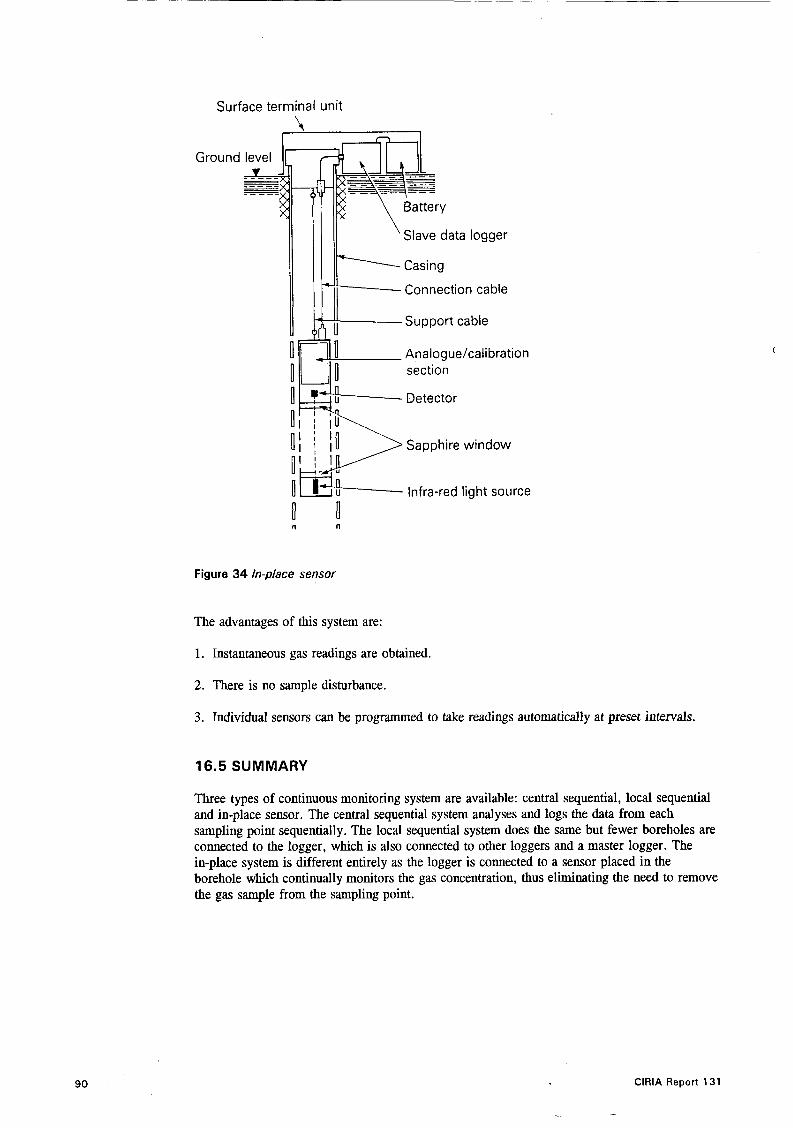
Surface terminal unit
1
Ground
I 1 II Slave data logger '
level 1 H j Support cable
_ _ _ _ - - _ - - -
Slave data logger
Connection cable
Analogue/cali bration section
Detector
0 1- Sapphire window
I d 0' I
0 Infra-red light source
n n
Figure 34 In-place sensor
The advantages of this system are:
1. Instantaneous gas readings are obtained.
2. There is no sample disturbance.
3. Individual sensors can be programmed to take readings automatically at preset intervals.
16.5 SUMMARY
Three types of continuous monitoring system are available: central sequential, local sequential and in-place sensor. The central sequential system analyses and logs the data from each sampling point sequentially. The local sequential system does the same but fewer boreholes are connected to the logger, which is also connected to other loggers and a master logger. The in-place system is different entirely as the logger is connected to a sensor placed in the borehole which continually monitors the gas concentration, thus eliminating the need to remove the gas sample from the sampling point.
90 ClRlA Report 131
. -

17 Monitoring in buildings
17.1 INTRODUCTION
, \
Monitoring the concentration of gas within a building is an important part of any post development programme. As with the external environment, the purpose of an internal monitoring system is to ensure that the environment remains safe, and that measures incorporated into the building to control gas ingress are working efficiently. There are two principal considerations in the design of any system for this purpose:
1. What type of detectors are most suitable
2. Where should the chosen detectors be positioned?
17.2 DETECTION SYSTEMS
Most of the detectors and sensors described in previous sections can be used as the basis for a multi-point fixed sampling system, although the most commonly used are probably the catalytic and infra-red based systems. These can be linked to automatic logging and warning systems connected either optically or electronically to a single central microprocessor based controller. The advantages and limitations of various detector types are discussed in Sections 9 and 10.
Whatever system is used there will be an on-going requirement for maintenance, checking and calibration of the sensors. Many systems which are microprocessor controlled have self-check facilities which will assist this process and give an early warning of detector failure. It may also be advisable in sensitive areas to fit two types of detector at the same location: this can help avoid problems of ‘common mode failure’, i.e. similar detectors failing by the same fault whether electrical or a result of the sampling conditions.
17.3 SENSOR LOCATION
There are many uncertainties and misconceptions concerning the positioning of detectors in buildings to measure gases which may enter from the ground. These tend to arise for two main reasons:
1. The major hazard is often perceived to arise from one gas only, usually methane; therefore the behaviour of the gas is assumed to emulate that of pure methane or natural gas.
2. No account is taken of the influence of other gases (e.g. carbon dioxide) on the nature of the mixture in terms of flammability, buoyancy and toxicity.
For example, landfill gas, as a mixture principally of methane and carbon dioxide, has a buoyancy that varies depending on the exact composition and temperature of the mixture. For a typical mixture, i.e. between 45 and 65 % methane under standard conditions, the buoyancy is close to that of air (Figure 3 9 , being either slightly more (65 % methane) or slightly less (45 % methane) buoyant than air. In addition, if the landfill gas contains nitrogen or is diluted by air before it enters the building, the buoyancy may be very similar to that of air. Under either circumstance the effect of buoyancy may be small and the behaviour of the gas will be governed to a great extent by the natural air flows and ventilation within the building.
ClRlA Report 131 91

0.5
0.4 I -
I
More Buoyant / 0.1
Neutral Buoyancy n _ _ - _ - - - - - - .,
-0.1
-0.2
-0.3
-0.4
-0.5
/ /
- - _ - - - -
Less Buoyant
-0.6 I I 1 1 I I 1 1 I I
90 1oc 0 10 2 0 30 40 50 60 70 80
Figure 35 Buoyancy of methanekarbon dioxide mixtures relative to air
KEY TO INGRESS ROUTES 1 . Through cracks in solid floors 2. Through construction joints 3. Through cracks in walls below ground level
4. Through gaps in suspended concrete or timber floor 5. Through gaps around service pipes 6. Through cavities in walls
'.
92
Figure 36 Gas entry into buildings
ClRlA Report 131

In all circumstances where gas could ingress from the ground below a building, sensors should be sited as close as possible to the likely routes of ingress at whatever height they exist. Additional sensors at ceiling height may provide further safety, but they should not be relied upon as the only location for gas detectors. Figure 36 highlights some of the potential routes of ingress for a typical domestic dwelling; corresponding locations on commercial properties would also have to be considered.
Within a building that may be subject to gas ingress from whatever source, suitable gas detectors should be considered in the following areas:
rooms with little or no natural ventilation
rooms containing potential sources of ignition, particularly electrical equipment, gas burners
underfloor and wall cavities where gas may collect and migrate
ducts and, if placed within the ground, sewers and drainage channels, which may form
as close as practicable to potential ingress points, e.g. wall/floor joints, service inlet points,
or boilers
routes for gas ingress
etc.
17.4 SUMMARY
Monitoring systems in buildings are generally based on the catalytic or infra-red type sensors, linked to automatic logging and warning systems. The positioning of the sensors should take into account buoyancy differences of the different gases present. Sensors should be sited close to likely gas ingress points, with additional sensors being placed at ceiling level.
ClRlA Report 131
Particular areas where monitoring may be necessary include rooms with little or no ventilation, rooms with potential ignition sources, underfloor and wall cavities, ducts, sewers and drainage channels.
93

References
1.
2.
3.
4.
5 .
6.
7.
8.
9.
10.
11.
12.
13.
INTERDEPARTMENTAL COMMITTEE ON THE REDEVELOPMENT OF CONTAMINATED LAND. Notes on the redevelopment and after-use of landfill sites. ICRCL Guidance Note 17/78, eighth edition, 1990.
DEPARTMENT OF THE ENVIRONMENT, HER MAJESTY'S INSPECTORATE OF POLLUTION. The control of landfill gas. Waste Management Paper No.27, HMSO, 1st Edition 1989, 2nd Edition 1991.
CREEDY, D. Geological Sources of Methane in Relation to Surface and Underground Hazards. Methane - Facing the problems symposium, Nottingham, UK, 26-28 September 1989.
DEPARTMENT OF THE ENVIRONMENT, PROPERTY SERVICES AGENCY. The Protection of Operationa l BuiLdings from Gas. PSA Report No.TAD(77)1, Directorate of Post Office Service, Croydon, 1977.
CREEDY, D. Hazardous Gases in the Mine Environment. Hazardous Gases in the Environment - A Seminar, North West Group, Institution of Geologists, UMIST, Manchester, UK, 10 April 1990.
GRAYSON, R. OLDHAM, L & CONNELL, S . Hydrogen Sulphide Springs in the Pennines and Adjacent Areas - A Neglected Hazard. Hazardous Gases in the Environment - A Seminar, North West Group, Institution of Geologists, UMIST, UK, 10 April 1990.
HOOKER, P.J. & BANNON, M.P. Methane: its occurrence and hazards in construction CIRIA Report 130, London, 1993.
BRITISH STANDARDS INSTITUTION. Draft for Development, Code of Practice for the Identijication of Potentially Contaminated Land and its Investigation. DD 175:1988.
INTERNATIONAL STANDARDS ORGANISATION. Technical Committee 190. Soil Quality - Sampling, Part 3: Guidance on Safety. Secretary Committee, EPC48 "Soil Quality". British Standards Institution.
SMITH, M. A. Safety Aspects of Waste Disposal to Landfill. Proceedings of 'The Planning and Engineering of Landfills' Midland Geotechnical Society, Birmingham, July 1991.
HEALTH & SAFETY EXECUTIVE. Avoiding Danger from Underground Services. Her Majesty's Stationery Office, 1989.
HEALTH & SAFETY EXECUTIVE. Guidance Note GS5. Entry into confined spaces. Her Majesty's Stationery Office.
\
SYPOL ENVIRONMENT MANAGEMENT LTD. A guide to the control of substances hazardous to health in design and construction. Unpublished report to CIRIA Core Programme Funders FR/CP/4 June 1992 (to be published).
94 ClRlA Report 131

14.
15.
16.
17.
18.
19.
20.
21.
22.
23.
24.
25.
26.
27.
28.
CONSTRUCTION INDUSTRY RESEARCH AND INFORMATION ASSOCIATION. Safe Working Practices for Contaminated Sites. CIRIA Report, London.
BRITISH DRILLING ASSOCIATION Guidance notes for the safe handling of landfills and contaminated sites. BDA, Brentwood, 1992.
SKYSCAN Publicity information, Stanway Grounds Farm, Stanway, Cheltenham, Glos.
WELTMAN, A. The use of Aerial Infra-red Photography for the Detection of Methane from Landfills. Ground Engineering, Vo1.6, No.3, pp22-23 April 1983.
BUTTERWORTH, J. S . Sampling, Analysis and Identification. Methane - Facing the Problems Symposium, Nottingham, UK, 26-28 September 1989.
BARROW, N. PEARSON, C.F.C. POWELL, P. EDWARDS, J. The Source and Extent of Hydrocarbon Gas Occurrances near to an Underground Zinc Mine at Navan, CO Meath, Ireland. Methane - Facing the Problems Symposium, Nottingham, UK, 26-28 March 1991.
FIRTH, J. G. Measurement of flammable gases and vapours. In: Detection and Measurement of Hazardous Gases. Edited by C.F. Cullis and J.G. Firth, Heinemann. London 1981.
PARTRIDGE, R.H. & CURTIS, I.H. Final Report on the Methane Measurements made with the NPL Diode Laser Remote Monitoring System at New Park Land’ll Site, Ugley, Stansted, Essex. National Physical Laboratory Report Qu 526. November 1986.
BRITISH STANDARDS INSTITUTION. Instruments for the Detection of Combustible Gases, Part 1-5. BS6020 1981.
BRITISH STANDARDS INSTITUTION. Gas Detector Tubes. BS5343 1976.
COOPER, L.R. Oxygen Deficiency, section 3. In: Detection and Measurement of Hazardous Gases. Edited by C.F. Cullis and J.G. Firth, Heinemann. London 1981.
THORBURN, S . COLENUTT, B.A. AND DOUGLAS, S.G. The sampling and gas chromatographic analysis of gases from landfill sites. International Journal of Environmental Analytical Chemistry, 6 (3) 245 - 254, 1979.
FLOWER, F.B. Case history of landfill gas movement through soils. In report by Gentelli et al. Gas and leachate from landfills, formation, collection and treatment. Rep. No. 600-9-76-004 p177 - 189. US EPA March 1984.
EMCON ASSOCIATES. Methane generation and recovery from landfills. Consolidated Concrete Ltd and Alberta Environment - Ann. Arbor. Science. Michigan, 1980.
Gas recovery & utilisationfrom a municipal waste disposal site. Environmental Protection Service Report. No EPS - 4 - EC - 81 - 2. 1981. Environmental Protection Service, Ottawa, Ontario, Canada.
CONESTOGA-ROVER & ASSOCIATES.
ClRlA Report 131 95
29.
30.
31.
32.
33.
34.
35.
36.
37.
38.
39.
WESTBAY INSTRUMENTS LTD, VANCOUVER, CANADA. The MP system for water pressure measurements, groundwater samples and permeability tests. Publicity material.
BLAKEY, N.C. & MARIS, P.J. Gas from Domestic Wastes in Landjills: Sampling and Analysis. Water Research Centre. Stevenage Laboratory. LR1144. March 1980.
MCBEAN, E.A. FARQUHAR, G.J. An examination of temporal and spatial variation in landfill generated methane gas. Water air soil pollution, 13, p157 - 172, 1980.
Lytwynshyn, G.R. Zimmerman, R.E. Flynn, N.W. Wingender, R. Oliveri, V. Lana‘jill methane recovery: Part II - Gas characterisation. Argonne National Laboratory, ANLKNSV-TM-118. IL (USA), December 1982.
LEACH, A. & MOSS, H.D.T. Landfll gas research and development studies: Calvert and Stewartby landfill sites, contractor report for Department of Energy, 1989.
JOHNSON, R.L. PANKOW, J.F. CHEXRY, J.A. Design of a Groundwater Sampler for Collecting Volatile Organics and Dissolved Gases in Small Diameter Wells. Groundwater Vo1.25, No.4, July - August 1987.
BARCELONA, M.J. HELFRICH, J.A. GARSKE, E.E. GIBB, J.P. A Laboratory Evaluation of Groundwater Sampling Mechanisms. Groundwater Monitoring Raiew. Vol. 4, p 32. Spring 1984.
NEWTON, J. Groundwater Investigation and Monitoring. Pollution Engineering. pp66-73, July 1989.
METHODS FOR THE ExtlMINATION OF WATERS AND ASSOCIATED MATERIALS. The Determination of Methane and Other Hydrocarbon Gases in Water 1988. Her Majesty’s Stationery Office, London, 1988.
BARBER, C. & BRIEGEL, D. A Method for the Determination of Dissolved Methane in Groundwater in Shallow Aquifers. Journal of Contaminant Hydrology, 2 (1987) pp51-60.
DEPARTMENT OF THE ENVIRONMENT. The Householder’s Guide to Radon. HMSO, July 1990.
96 ClRlA Report 131

Appendix A Standards and codes of practice relevant to safety in site investigations for gas
BS 4683:
Part 1:1971
Part 2: 1971
Part 3: 1972
Part 4: 1973
BS 5343:
Part2: 1991
BS 5345:
Part 1: 1976
Part2: 1983
Part3: 1979
Part4: 1977
Part 6: 1978
Part7: 1979
BS 5573: 1978
BS 5930: 1981
BS 6020:
Part 1: 1981
Part2: 1981
Part 3: 1982
Part4: 1981
Part5: 1982
BS 6164: 1990
DD 175: 1988
Electrical Apparatus for &plosive Atmospheres:
Classijication of maximum surface temperatures.
The construction and testing of jkmeproof enclosures of electrical apparatus.
Type of protection N.
Type of protection ‘e ’.
Specijication for long-term gas detector tubes.
Selection, installation and maintenance of ‘electrical apparatus for use in explosive atmospheres (other than mining applications or explosive processing and manufacture).
Basic requirements for all parts of the code.
Classification of hazardous areas.
Installation and maintenance requirements for electrical apparatus with type of protection ‘d ’. Fhmeproof enclosure.
Installation and maintenance requirements for electrical apparatus with type of protection ‘i ’. Intrinsically safe electrical apparatus and systems.
Installation and maintenance requirements for electrical apparatus with type of protection ‘e’. Increased safety.
Installation and maintenance requirements for electrical apparatus with type of protection ‘N’.
Code of practice for safety precautions in the construction of large diameter boreholes for piling and other purposes.
Code of practice for site investigations.
Instruments for the detection of combustible gases.
Specification for general requirements and test methods. Svecification for safety and performance requirements for Group I instruments reading up to 5 % methane in air.
Specijication for safety and performance requirements for Group 1 instruments reading up to IOOW methane.
Specification for performance requirements for Group 11 instruments reading up to IOO% lower explosive limit.
Specification for performance requirements for Group 11 instruments reading up to 100% gas.
Safety in tunnelling in the construction industry.
Code of practice for the identification of potentially contaminated land and its investigation.
ClRlA Report 131 97

98
Health & Safety Executive. Protection of personnel and the general public during development of contaminated land, HS(G) 66, HMSO, 1991
Health & Safety Commission. Control of substances hazardous to health (General ACoP - second edition) and Control of carcinogenic substances (Carcinogens ACoP - second edition): Approved codes of practice’. HMSO, London, 1990.
Health & Safety Executive. Avoiding danger from underground services. HMSO, London, 1989.
Health & Safety Executive. Guidance Note GS5. Entry into Conjlned Spaces. HMSO, London, 1977.
International Standards Organisation. Technical Committee 190, Soil quality. For information contact Secretary Committee EPC48 ‘Soil quality,’ British Standards Institution, London.
. .. ClRlA Report 131

Core Programme, Members (July 1993) Consultants
ACER Consultants Ltd Ove Arup Partnership W S Atkins Consultants Limited Babtie Group Ltd Binnie & Partners Building Design Partnership Brian Colquhoun & Partners Sir Alexander Gibb & Partners Limited Frank Graham Group Limited Sir William Halcrow & Partners Ltd G Maunsell & Partners Montgomery Watson Ltd Mott MacDonald Group Ltd L G Mouchel & Partners Ltd Posford Duvivier Rendel Palmer & Tritton Rofe Kennard & Lapworth Scott Wilson Kirkpatrick & Partners Wardell Armstrong Sir Owen Williams and Partners Geotechnical Ltd
Water Utilities
Northumbrian Water Limited North West Water Limited South West Water Services Ltd Southern Water Services Ltd Thames Water Utilities Ltd Wessex Water plc Yorkshire Water Services Ltd
Contractors
AMEC p.1.c. Balfour Beatty Ltd Henry Boot & Sons PLC Galliford plc Higgs & Hill Construction Holdings Ltd Kyle Stewart Design Services Ltd Laing Technology Group Ltd Alfred McAlpine Construction Ltd Miller Civil Engineering Ltd Edmund Nuttall Limited Tarmac Construction Ltd Taylor Woodrow Construction Holdings Ltd Trafalgar House Technology Willmott Dixon Ltd George Wimpey PLC
Others
British Telecom Cementitious Slag Makers Association Department of the Environment Department of Transport Health & Safety Executive Hong Kong Government Secretariat H R Wallingford Ltd ICI Engineering Institution of Civil Engineers London Underground Limited National Power National Rivers Authority PSA Projects Limited Scottish Hydro-Electric plc Union Railways Limited

..
ClRlA 0 ClRlA is the Construction Industry Research andlnformation Association. It is a non-profitdistributing, private sector organisation carrying out research and providing information for its members, who include all types o f organisations concerned with construction, including clients, professional practices, contractors, suppliers, educational and research establishments. professional institutions,
trade associations, central and local government.
ClRlA focuses on providing best practice guidance to professionals
#*
. that is authoritative, convenient to use and relevant. Areas covered include construction practice, building design and materials, management, ground engineering, water engineering and environmental issues.
Through active participation, ClRlA members choose research and information projects of most value to them. Funding contributions are sought from member subscriptions and from government and other sources on a project by project basis. Detailed work is contracted to the best qualified organisation selected in competition. and each project is guided b y a project steering group, which contains both individual specialists and representatives of different groups with experience or interest in the topic.
ClRlA offers a number o f different participation routes as follows:
Core Programme Sponsorship. Core Programme members, who include many of the most significant construction firms, choose the programme of research projects and obtain privileged early access t o results.
Construction Industry Environmentbl Forum. Run in association with ERE and BSRIA, the Forum provides a focus for crossindustry discussion and information on environmental matters.
Associates/Affiliites. Subscribers obtain copies of ClRlA open publications on favourable terms and get discounts on ClRlA seminars.
Support for Individual Projects. Organisations can participate financially and technically in single projects of interest to them.
Purchase of Publications. ClRlA publications, together with selected publications from other sources, are available by mail order or on personal application.
SeminarslConferences. ClRlA runs a number of events, often related to research projects or publications.
ClRlA News. A quarterly newsletter is available free on request
For further details, please apply to the Membership Manager, CIRIA, 6 Storey’s Gate, London SW1 P 3AU. Tel: 07 1-222 889 1. Fax: 07 1-222 1708.