Embed Size (px)
Citation preview
THE MICROCANOPEN PROTCOL STACK
1
MICROCANOPEN USER MANUAL
Revision 331 for Version 3.30 of MicroCANopen Plus
THE MICROCANOPEN PROTCOL STACK
2
MICROCANOPEN EDUCATIONAL LICENSE EMBEDDED SYSTEMS ACADEMY, INC.
For MicroCANopen V3.30
You should carefully read the following terms and conditions before using this software. Unless you have a different license agreement signed by Embedded Systems Academy, Inc. ("ESA") your use of this copy of MicroCANopen (the "SOFTWARE") indicates your acceptance of this license.
If you do not agree to any of the terms of this License, then do not use this copy of the SOFTWARE.
If the SOFTWARE is used for a project that is rented, leased, sold or otherwise traded (a "COMMERCIAL PROJECT") then the commercial license is required to use the SOFTWARE. If the SOFTWARE is used to develop knowledge of CANopen for a COMMERCIAL PROJECT then the commercial license is required.
This is a free license, with the most important aspect being: YOU MAY NOT RENT, LEASE OR SELL THE SOFTWARE OR USE OR INCLUDE THE SOFTWARE IN COMMERCIAL PROJECTs.
Installation and Use. You may install and use an unlimited number of copies of the SOFTWARE. Reproduction and Distribution. You may not reproduce and distribute copies of the SOFTWARE without written permission of ESA.
All title and copyrights in and to the SOFTWARE (including but not limited to any images, photographs, animations, video, audio, music, text, and "applets" incorporated into the SOFTWARE), any accompanying printed materials, and any copies of the SOFTWARE are owned by ESA. The SOFTWARE is protected by copyright laws and international treaty provisions. Therefore, you must treat the SOFTWARE like any other copyrighted material. All copyright notices, this license, header comments and similar statements include with this distribution of the SOFTWARE must remain in the source code at all times. No claim must be made as to the ownership of the SOFTWARE.
THIS SOFTWARE, AND ALL ACCOMPANYING FILES, DATA AND MATERIALS, ARE DISTRIBUTED "AS IS" AND WITH NO WARRANTIES OF ANY KIND, WHETHER EXPRESS OR IMPLIED. Good data processing procedure dictates that any program be thoroughly tested with non-critical data before relying on it. The user must assume the entire risk of using the program. THIS DISCLAIMER OF WARRANTY CONSTITUTES AN ESSENTIAL PART OF THE AGREEMENT.
IN NO EVENT SHALL ESA, OR ITS PRINCIPALS, SHAREHOLDERS, OFFICERS, EMPLOYEES, AFFILIATES, CONTRACTORS, SUBSIDIARIES, OR PARENT ORGANIZATIONS, BE LIABLE FOR ANY INCIDENTAL,
THE MICROCANOPEN PROTCOL STACK
3
CONSEQUENTIAL, OR PUNITIVE DAMAGES WHATSOEVER RELATING TO THE USE OF THE SOFTWARE, OR YOUR RELATIONSHIP WITH ESA.
IN ADDITION, IN NO EVENT DOES ESA AUTHORIZE YOU TO USE THE SOFTWARE IN APPLICATIONS OR SYSTEMS WHERE THE SOFTWARE'S FAILURE TO PERFORM CAN REASONABLY BE EXPECTED TO RESULT IN A SIGNIFICANT PHYSICAL INJURY, OR IN LOSS OF LIFE. ANY SUCH USE BY YOU IS ENTIRELY AT YOUR OWN RISK, AND YOU AGREE TO HOLD ESA HARMLESS FROM ANY CLAIMS OR LOSSES RELATING TO SUCH UNAUTHORIZED USE.
This Agreement is the complete statement of the Agreement between the parties on the subject matter, and merges and supersedes all other or prior understandings, purchase orders, agreements and arrangements. This Agreement shall be governed by the laws of the State of California. Exclusive jurisdiction and venue for all matters relating to this Agreement shall be in courts located in the State of California, and you consent to such jurisdiction and venue.
All rights of any kind in the SOFTWARE which are not expressly granted in this License are entirely and exclusively reserved to and by ESA.
THE MICROCANOPEN PROTCOL STACK
4
TABLE OF CONTENTS
TABLE OF CONTENTS.................................................................................................... 4
1 THE MICROCANOPEN PROTOCOL STACK........................................................ 6
1.1 MICROCANOPEN AND MICROCANOPEN PLUS ....................................... 6
1.2 MICROCANOPEN MANAGER ADD-ON....................................................... 6
1.3 CANOPEN DOCUMENTATION...................................................................... 6
1.4 FILE AND DIRECTORY STRUCTURE .......................................................... 6
1.5 FUNCTION SUMMARY................................................................................... 8
1.6 DS401 GENERIC I/O EXAMPLE APPLICATION.......................................... 9
2 APPLICATION INTERFACE ................................................................................. 10
2.1 THE PROCESS IMAGE .................................................................................. 10
2.1.1 CONFIGURATION OF THE PROCESS IMAGE .................................. 10
2.1.2 CONSTANT EXPEDITED OBJECT DICTIONARY ENTRIES ........... 11
2.1.3 VARIABLE EXPEDITED AND MAPPED OBJECT DICTIONARY ENTRIES .................................................................................................................. 12
2.1.4 GENERIC OBJECT DICTIONARY ENTRIES (PLUS) ......................... 12
2.2 CANOPEN API FUNCTIONS......................................................................... 13
2.2.1 The MCO_Init function ............................................................................ 13
2.2.2 The MCO_InitRPDO function.................................................................. 14
2.2.3 The MCO_InitTPDO function.................................................................. 14
2.3 CANOPEN API CALL-BACK FUNCTIONS................................................. 15
2.3.1 The MCOUSER_ResetApplication function............................................ 15
2.3.2 The MCOUSER_ResetCommunication function..................................... 16
2.3.3 The MCOUSER_FatalError function ....................................................... 16
2.4 DRIVER FUNCTIONS .................................................................................... 17
2.4.1 The MCOHW_Init function...................................................................... 17
2.4.2 The MCOHW_SetCANFilter function..................................................... 17
2.4.3 The MCOHW_PushMessage function ..................................................... 17
2.4.4 The MCOHW_PullMessage function....................................................... 18
2.4.5 The MCOHW_GetTime function............................................................ 18
THE MICROCANOPEN PROTCOL STACK
5
2.4.6 The NVOL_ReadByte function............................................................... 18
2.4.7 The NVOL_WriteByte function .............................................................. 19
3 CANOPEN CODE CONFIGURATION.................................................................. 20
3.1 TABLE SIZE SETTINGS OF PROCIMG.H................................................... 20
3.1.1 #define PROC_IMGSIZE [auto generated] .............................................. 20
3.2 GENERAL SETTINGS OF NODECFG.H...................................................... 20
3.2.1 #define CHECK_PARAMETERS............................................................ 20
3.3 PDO SETTINGS OF NODECFG.H................................................................. 20
3.3.1 #define NR_OF_RPDOS [auto generated]............................................... 20
3.3.2 #define NR_OF_TPDOS [auto generated] .............................................. 20
3.3.3 #define USE_EVENT_TIME................................................................... 20
3.3.4 #define USE_INHIBIT_TIME ................................................................. 21
3.4 NMT SERVICE SETTINGS OF NODECFG.H (PLUS) ................................. 21
3.4.1 #define AUTOSTART.............................................................................. 21
3.4.2 #define USE_MICROLSS........................................................................ 21
3.4.3 #define DEFAULT_HEARTBEAT [auto generated] ............................. 21
4 USING AUTO-GENERATED SOURCES .............................................................. 22
4.1 FILE GENERATION ....................................................................................... 22
4.2 FILE INTEGRATION...................................................................................... 22
4.2.1 PIMG.H..................................................................................................... 22
4.2.2 INITPDOS.H............................................................................................. 23
4.2.3 ENTRIESANDREPLIES.H...................................................................... 23
THE MICROCANOPEN PROTCOL STACK
6
1 THE MICROCANOPEN PROTOCOL STACK
The MicroCANopen protocol stack implements all mandatory functionality of the CiA (CAN in Automation user’s and manufacturer’s group) standard DS301 “CANopen Application Layer and Communication Profile” version 4.02. The examples included are in accordance to the standard DS401 “CANopen Device Profile for Generic I/O Modules” version 2.1. Examples implementations for other Device or Application Profiles are available upon request.
1.1 MICROCANOPEN AND MICROCANOPEN PLUS This manual covers MicroCANopen, see www.microcanopen.com for more info on the “Plus” version. The “Plus” version is included with the Development System version of the CANopen configuration and test utility “CANopen Magic ProDS”.
1.2 MICROCANOPEN MANAGER ADD-ON Advanced CANopen Manager Functionality as defined in “CANopen Framework for CANopen Managers and Programmable CANopen Devices” is available as an add-on package to MicroCANopen Plus. For details see the MicroCANopen Plus Manager User Manual or www.CANopenStore.com.
1.3 CANOPEN DOCUMENTATION It is assumed that programmers using MicroCANopen have a general understanding about how CANopen works. In addition they should either have access to the CANopen specification or a CANopen book such as “Embedded Networking with CAN and CANopen” (www.CANopenBook.com). The MicroCANopen manual does not explain regular CANopen features, functions and terms.
1.4 FILE AND DIRECTORY STRUCTURE The directory structure used by MicroCANopen separates the files used into four major groups. It is recommended to maintain this structure and to adopt it for the grouping of source files in the project settings and layouts as supported by most compiler systems.
THE MICROCANOPEN PROTCOL STACK
7
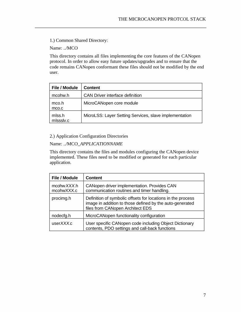
1.) Common Shared Directory:
Name: ../MCO
This directory contains all files implementing the core features of the CANopen protocol. In order to allow easy future updates/upgrades and to ensure that the code remains CANopen conformant these files should not be modified by the end user.
File / Module Content
mcohw.h CAN Driver interface definition
mco.h mco.c
MicroCANopen core module
mlss.h mlssslv.c
MicroLSS: Layer Setting Services, slave implementation
2.) Application Configuration Directories
Name: ../MCO_APPLICATIONNAME
This directory contains the files and modules configuring the CANopen device implemented. These files need to be modified or generated for each particular application.
File / Module Content
mcohwXXX.h mcohwXXX.c
CANopen driver implementation. Provides CAN communication routines and timer handling.
procimg.h Definition of symbolic offsets for locations in the process image in addition to those defined by the auto-generated files from CANopen Architect EDS
nodecfg.h MicroCANopen functionality configuration
userXXX.c User specific CANopen code including Object Dictionary contents, PDO settings and call-back functions
THE MICROCANOPEN PROTCOL STACK
8
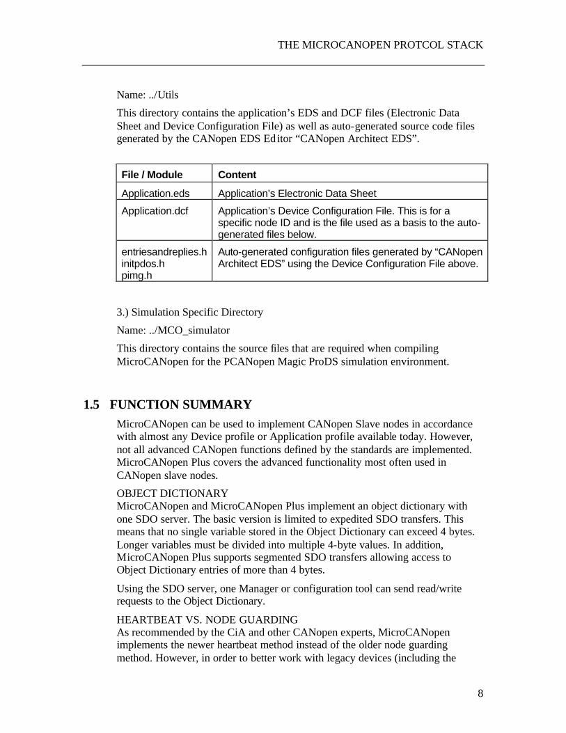
Name: ../Utils
This directory contains the application’s EDS and DCF files (Electronic Data Sheet and Device Configuration File) as well as auto-generated source code files generated by the CANopen EDS Editor “CANopen Architect EDS”.
File / Module Content
Application.eds Application’s Electronic Data Sheet
Application.dcf Application’s Device Configuration File. This is for a specific node ID and is the file used as a basis to the auto-generated files below.
entriesandreplies.h initpdos.h pimg.h
Auto-generated configuration files generated by “CANopen Architect EDS” using the Device Configuration File above.
3.) Simulation Specific Directory
Name: ../MCO_simulator
This directory contains the source files that are required when compiling MicroCANopen for the PCANopen Magic ProDS simulation environment.
1.5 FUNCTION SUMMARY MicroCANopen can be used to implement CANopen Slave nodes in accordance with almost any Device profile or Application profile available today. However, not all advanced CANopen functions defined by the standards are implemented. MicroCANopen Plus covers the advanced functionality most often used in CANopen slave nodes.
OBJECT DICTIONARY MicroCANopen and MicroCANopen Plus implement an object dictionary with one SDO server. The basic version is limited to expedited SDO transfers. This means that no single variable stored in the Object Dictionary can exceed 4 bytes. Longer variables must be divided into multiple 4-byte values. In addition, MicroCANopen Plus supports segmented SDO transfers allowing access to Object Dictionary entries of more than 4 bytes.
Using the SDO server, one Manager or configuration tool can send read/write requests to the Object Dictionary.
HEARTBEAT VS. NODE GUARDING As recommended by the CiA and other CANopen experts, MicroCANopen implements the newer heartbeat method instead of the older node guarding method. However, in order to better work with legacy devices (including the
THE MICROCANOPEN PROTCOL STACK
9
CANopen conformance test) MicroCANopen Plus also has a very basic version of node guarding implemented.
MICROCANOPEN PDO PARAMETERS In MicroCANopen all PDO parameters (communication and mapping) are hard-coded and cannot change during operation. PDO trigger options include time driven as well as event driven with an inhibit time.
NUMBER OF PDOS The maximum number of PDOs supported are 4 TPDOs and 4 RPDOs for the educational version of MicroCANopen.
LAYER SETTING SERVICES Using the layer setting services, MicroCANopen based nodes can change their node ID. The optimized MicroLSS for slaves was implemented for MicroCANopen.
USER CALL-BACK FUNCTIONS MicroCANopen provides call-back functions for the resets and for fatal errors. The reset function is typically used to initialize the entire CANopen stack.
1.6 DS401 GENERIC I/O EXAMPLE APPLICATION The example code supplied with MicroCANopen implements a minimal DS401 compliant device with 4 digital input bytes, 4 digital output bytes, 2 analog input words and 2 analog output words. The process data is transmitted using 2 Transmit PDOs and 2 Receive PDOs.
The output data send to the application is directly echoed back as input data. Values send to RPDO1 are echoed back on TPDO1, values send to RPDO2 are echoed back on TPDO2.
THE MICROCANOPEN PROTCOL STACK
10
2 APPLICATION INTERFACE
Both shared data memory and function calls are used to implement an interface between MicroCANopen the application program. A process image (array of bytes) is used as shared memory that can be accessed from both MicroCANopen as well as from the application program. The process image contains all process data variables that are communicated via CANopen. Access functions are provided to allow the application program to read or write data from or to the process image.
2.1 THE PROCESS IMAGE In order to offer a generic method for addressing and exchanging the data communicated via CANopen, the data is organized into a process image which is implemented as an array of bytes. The length of the process image in bytes is defined by PROCIMG_SIZE in file procimg.h and must be in the range of 1 to FEh (values 0 and FFh are reserved).
A single variable of the process image can be addressed by specifying an offset and a length. The offset specifies where in the process image the first byte of a variable is stored and the length specifies how many bytes are used to store the variable. The offset may have a value from 0 to FEh. Using an offset of FFh indicates that the offset is invalid or unused.
If numeric values are stored in multiple byte variables, then the default byte order is CANopen compatible: Little Endian – the lower bytes are stored at the lower offset.
2.1.1 CONFIGURATION OF THE PROCESS IMAGE
Since version 2.6 the process image configuration can be automatically generated by CANopen Architect EDS. The default file name for the file containing the process image variable definitions is pimg.h.
Where exactly each variable is located in the process image is part of the CANopen node configuration process that needs to be done by the designer/programmer of the CANopen node. The CANopen configuration process also includes assigning an Object Dictionary Index and Subindex to each variable and to configure the PDOs (Process Data Objects) containing one or multiple process data variables.
To simplify accessing the process image and to allow for easy re-configuration of process images, it is recommended to use #define statements to define the offsets to the individual variables in the process image. These should be defined in the
THE MICROCANOPEN PROTCOL STACK
11
file procimg.h that can be included to all code modules requiring access to the process image.
In MicroCANopen it MUST be ensured that all variables mapped into one PDO (one CAN message) are located consecutively in the process image. The entire contents of PDOs is copied byte-by-byte from/to the process image.
ACCESSING THE PROCESS IMAGE
Any application program may directly access the data in the process image (for example: gProcImg[offset] = x ).
The “Plus” version also provides the functions MCO_ReadProcessData() and MCO_WriteProcessData(). These can be used for compatibility with other implementations and in order to potentially protect the data consistency and integrity.
OBJECT DICTIONARY CONFIGURATION
Since version 2.6 the Object Dictionary configuration can be automatically generated by CANopen Architect EDS. The default file name for the file containing the process image variable definitions is entriesandreplies.h.
Although working with CANopen EDS and DCF files is the standard procedure for many CANopen configuration tools, many embedded CANopen nodes require a specific default configuration that a node should use if not configured through a CANopen configuration tool or by a CANopen Configuration Manager.
In MicroCANopen the default configuration is setup via tables typically implemented in a file called user_xxx.c (User Object Dictionary file).
The tables gSDOResponseTable and gODProcTable (the later not being available in the educational version) define the contents of the Object Dictionary. When using auto-generated files the auto-generated data can be included into these tables using the Macros SDOREPLY_ENTRIES, ODENTRY_ENTRIES and ODGENTRY_ENTRIES.
2.1.2 CONSTANT EXPEDITED OBJECT DICTIONARY ENTRIES
The gSDOresponseTable table
The table gSDOresponseTable is an array of bytes that contains a list of SDO responses for SDO requests to constant, read-only entries in the object dictionary limited to 4 bytes or less. Typically these contain the [1000,00] Device Type entry, the [1018,xx] Identity Objects and some “Number of Entries” type entries with a Subindex of zero.
Each entry in this list has 8 bytes that directly contain the 8 bytes used in a CAN message with an expedited SDO response to a read (upload) request.
THE MICROCANOPEN PROTCOL STACK
12
The macros SDOREPLY and SDOREPLY4 are provided to ease the generation of the 8-byte entries.
The last entry must be 8 times 0xFF to indicate the end of the table.
The current implementation does not require that the entries are sorted in any way.
The SDOREPLY macro
This macro generates the 8-byte SDO response required for a read (upload) request from an Object Dictionary entry with a constant entry.
SDOREPLY(INDEX,SUBINDEX,LENGTH,VALUE)
INDEX is the 16-bit Index of the Object Dictionary entry.
SUBINDEX is the 8-bit Subindex of the Object Dictionary entry.
LENGTH is the length of the Object Dictionary entry in bytes and must be in the range of 1 to 4.
VALUE is the value of the Object Dictionary entry. It must be defined as a 32-bit value even if LENGTH is less than 4-bytes. In that case the unused bytes must be set to zero.
The Object Dictionary entry [1000h,00h] with a value of 00030191h can be generated by: SDOREPLY(0x1000,0x00,4,0x00030191L),
The SDOREPLY4 macro
This macro generates the 8-byte SDO response required for a read (upload) request from an Object Dictionary entry with a constant entry of 4 bytes with an ASCII interpretation. This simplifies the generation of 32-bit Object Dictionary entries whose contents are not interpreted as a 32-bit value but as 4 characters.
SDOREPLY4(INDEX,SUBINDEX,CHAR1,CHAR2,CHAR3,CHAR4)
INDEX is the 16-bit Index of the Object Dictionary entry.
SUBINDEX is the 8-bit Subindex of the Object Dictionary entry.
CHAR1 through CHAR4 contain the 4 characters stored at this Object Dictionary entry.
2.1.3 VARIABLE EXPEDITED AND MAPPED OBJECT DICTIONARY ENTRIES
This gODProcTable is not supported by the educational version.
2.1.4 GENERIC OBJECT DICTIONARY ENTRIES (PLUS)
This gODGenericTable is not supported by the educational version.
THE MICROCANOPEN PROTCOL STACK
13
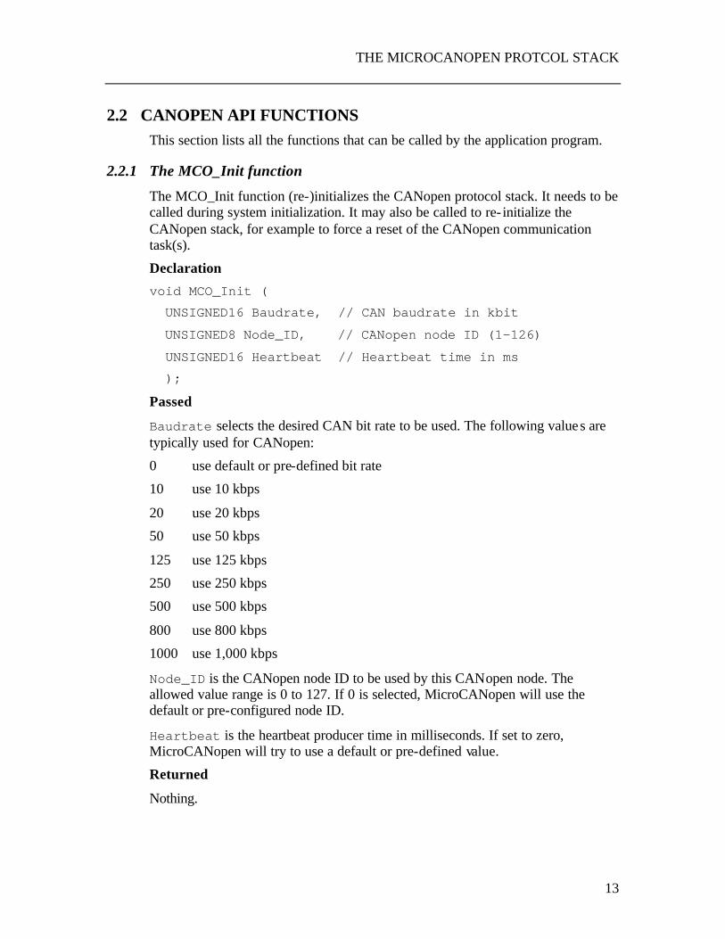
2.2 CANOPEN API FUNCTIONS This section lists all the functions that can be called by the application program.
2.2.1 The MCO_Init function
The MCO_Init function (re-)initializes the CANopen protocol stack. It needs to be called during system initialization. It may also be called to re- initialize the CANopen stack, for example to force a reset of the CANopen communication task(s).
Declaration
void MCO_Init ( UNSIGNED16 Baudrate, // CAN baudrate in kbit
UNSIGNED8 Node_ID, // CANopen node ID (1-126)
UNSIGNED16 Heartbeat // Heartbeat time in ms );
Passed
Baudrate selects the desired CAN bit rate to be used. The following values are typically used for CANopen:
0 use default or pre-defined bit rate
10 use 10 kbps
20 use 20 kbps
50 use 50 kbps
125 use 125 kbps
250 use 250 kbps
500 use 500 kbps
800 use 800 kbps
1000 use 1,000 kbps
Node_ID is the CANopen node ID to be used by this CANopen node. The allowed value range is 0 to 127. If 0 is selected, MicroCANopen will use the default or pre-configured node ID.
Heartbeat is the heartbeat producer time in milliseconds. If set to zero, MicroCANopen will try to use a default or pre-defined value.
Returned
Nothing.
THE MICROCANOPEN PROTCOL STACK
14
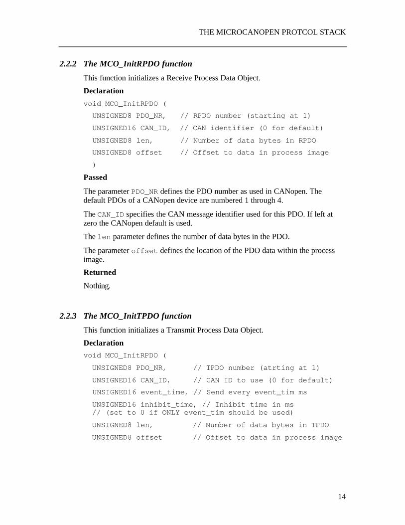
2.2.2 The MCO_InitRPDO function
This function initializes a Receive Process Data Object.
Declaration
void MCO_InitRPDO ( UNSIGNED8 PDO_NR, // RPDO number (starting at 1)
UNSIGNED16 CAN_ID, // CAN identifier (0 for default)
UNSIGNED8 len, // Number of data bytes in RPDO UNSIGNED8 offset // Offset to data in process image
)
Passed
The parameter PDO_NR defines the PDO number as used in CANopen. The default PDOs of a CANopen device are numbered 1 through 4.
The CAN_ID specifies the CAN message identifier used for this PDO. If left at zero the CANopen default is used.
The len parameter defines the number of data bytes in the PDO.
The parameter offset defines the location of the PDO data within the process image.
Returned
Nothing.
2.2.3 The MCO_InitTPDO function
This function initializes a Transmit Process Data Object.
Declaration void MCO_InitRPDO (
UNSIGNED8 PDO_NR, // TPDO number (atrting at 1)
UNSIGNED16 CAN_ID, // CAN ID to use (0 for default) UNSIGNED16 event_time, // Send every event_tim ms
UNSIGNED16 inhibit_time, // Inhibit time in ms // (set to 0 if ONLY event_tim should be used)
UNSIGNED8 len, // Number of data bytes in TPDO
UNSIGNED8 offset // Offset to data in process image
THE MICROCANOPEN PROTCOL STACK
15
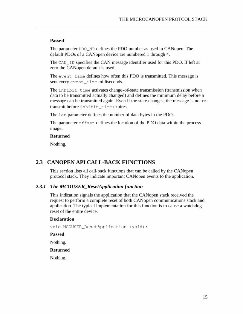
Passed
The parameter PDO_NR defines the PDO number as used in CANopen. The default PDOs of a CANopen device are numbered 1 through 4.
The CAN_ID specifies the CAN message identifier used for this PDO. If left at zero the CANopen default is used.
The event_time defines how often this PDO is transmitted. This message is sent every event_time milliseconds.
The inhibit_time activates change-of-state transmission (transmission when data to be transmitted actually changed) and defines the minimum delay before a message can be transmitted again. Even if the state changes, the message is not re-transmit before inhibit_time expires.
The len parameter defines the number of data bytes in the PDO.
The parameter offset defines the location of the PDO data within the process image.
Returned
Nothing.
2.3 CANOPEN API CALL-BACK FUNCTIONS This section lists all call-back functions that can be called by the CANopen protocol stack. They indicate important CANopen events to the application.
2.3.1 The MCOUSER_ResetApplication function
This indication signals the application that the CANopen stack received the request to perform a complete reset of both CANopen communications stack and application. The typical implementation for this function is to cause a watchdog reset of the entire device.
Declaration
void MCOUSER_ResetApplication (void);
Passed
Nothing.
Returned
Nothing.
THE MICROCANOPEN PROTCOL STACK
16
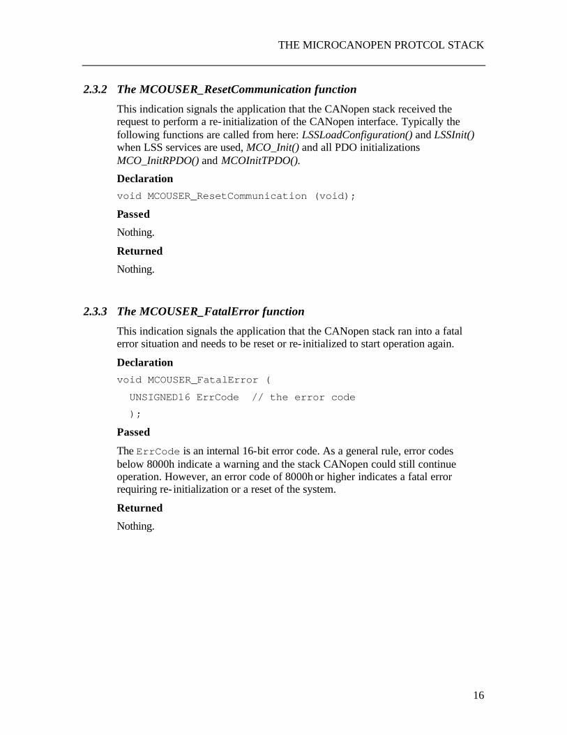
2.3.2 The MCOUSER_ResetCommunication function
This indication signals the application that the CANopen stack received the request to perform a re- initialization of the CANopen interface. Typically the following functions are called from here: LSSLoadConfiguration() and LSSInit() when LSS services are used, MCO_Init() and all PDO initializations MCO_InitRPDO() and MCOInitTPDO().
Declaration void MCOUSER_ResetCommunication (void);
Passed
Nothing.
Returned
Nothing.
2.3.3 The MCOUSER_FatalError function
This indication signals the application that the CANopen stack ran into a fatal error situation and needs to be reset or re- initialized to start operation again.
Declaration void MCOUSER_FatalError (
UNSIGNED16 ErrCode // the error code );
Passed
The ErrCode is an internal 16-bit error code. As a general rule, error codes below 8000h indicate a warning and the stack CANopen could still continue operation. However, an error code of 8000h or higher indicates a fatal error requiring re- initialization or a reset of the system.
Returned
Nothing.
THE MICROCANOPEN PROTCOL STACK
17
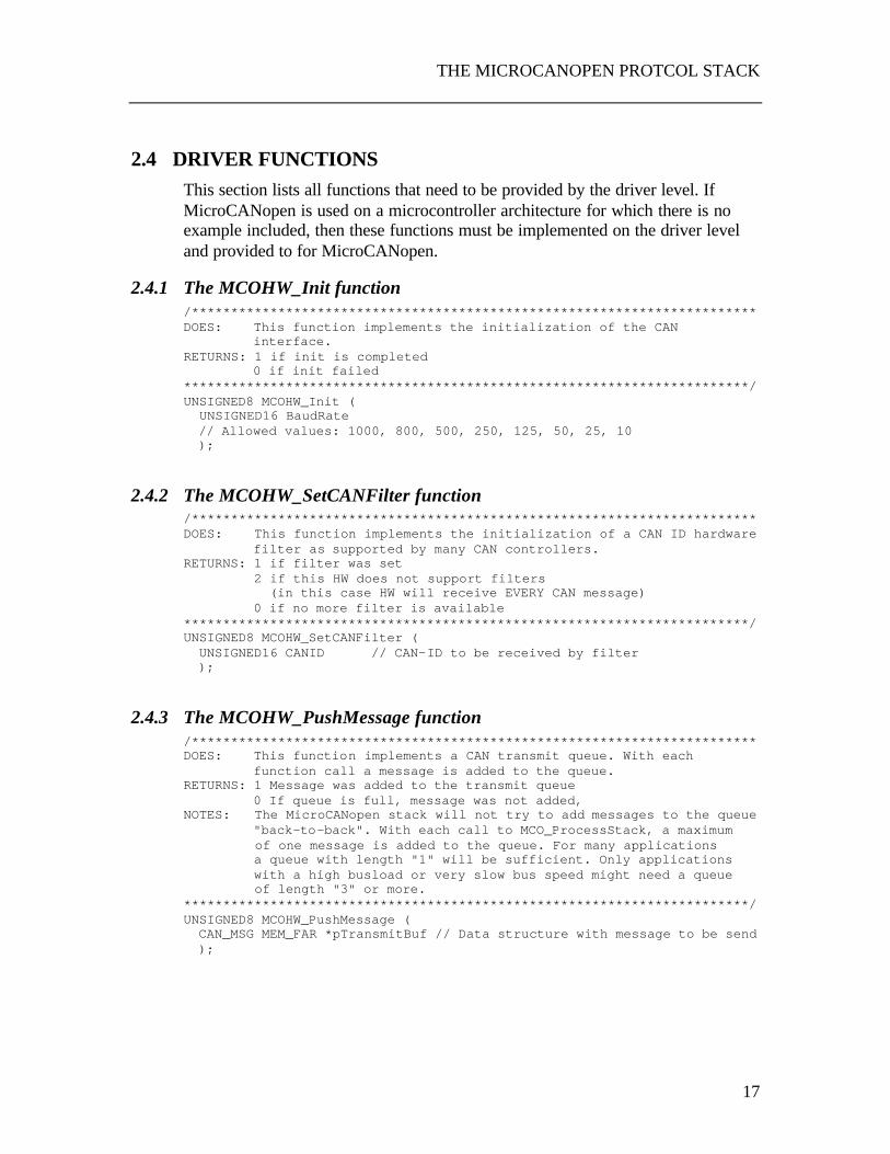
2.4 DRIVER FUNCTIONS This section lists all functions that need to be provided by the driver level. If MicroCANopen is used on a microcontroller architecture for which there is no example included, then these functions must be implemented on the driver level and provided to for MicroCANopen.
2.4.1 The MCOHW_Init function /************************************************************************ DOES: This function implements the initialization of the CAN interface. RETURNS: 1 if init is completed 0 if init failed ************************************************************************/ UNSIGNED8 MCOHW_Init ( UNSIGNED16 BaudRate // Allowed values: 1000, 800, 500, 250, 125, 50, 25, 10 );
2.4.2 The MCOHW_SetCANFilter function /************************************************************************ DOES: This function implements the initialization of a CAN ID hardware filter as supported by many CAN controllers. RETURNS: 1 if filter was set 2 if this HW does not support filters (in this case HW will receive EVERY CAN message) 0 if no more filter is available ************************************************************************/ UNSIGNED8 MCOHW_SetCANFilter ( UNSIGNED16 CANID // CAN-ID to be received by filter );
2.4.3 The MCOHW_PushMessage function /************************************************************************ DOES: This function implements a CAN transmit queue. With each function call a message is added to the queue. RETURNS: 1 Message was added to the transmit queue 0 If queue is full, message was not added, NOTES: The MicroCANopen stack will not try to add messages to the queue "back-to-back". With each call to MCO_ProcessStack, a maximum of one message is added to the queue. For many applications a queue with length "1" will be sufficient. Only applications with a high busload or very slow bus speed might need a queue of length "3" or more. ************************************************************************/ UNSIGNED8 MCOHW_PushMessage ( CAN_MSG MEM_FAR *pTransmitBuf // Data structure with message to be send );
THE MICROCANOPEN PROTCOL STACK
18
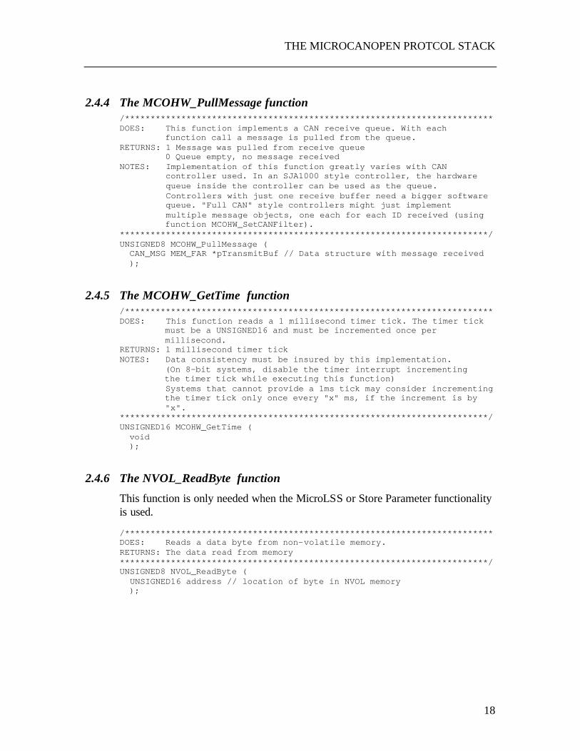
2.4.4 The MCOHW_PullMessage function /************************************************************************ DOES: This function implements a CAN receive queue. With each function call a message is pulled from the queue. RETURNS: 1 Message was pulled from receive queue 0 Queue empty, no message received NOTES: Implementation of this function greatly varies with CAN controller used. In an SJA1000 style controller, the hardware queue inside the controller can be used as the queue. Controllers with just one receive buffer need a bigger software queue. "Full CAN" style controllers might just implement multiple message objects, one each for each ID received (using function MCOHW_SetCANFilter). ************************************************************************/ UNSIGNED8 MCOHW_PullMessage ( CAN_MSG MEM_FAR *pTransmitBuf // Data structure with message received );
2.4.5 The MCOHW_GetTime function /************************************************************************ DOES: This function reads a 1 millisecond timer tick. The timer tick must be a UNSIGNED16 and must be incremented once per millisecond. RETURNS: 1 millisecond timer tick NOTES: Data consistency must be insured by this implementation. (On 8-bit systems, disable the timer interrupt incrementing the timer tick while executing this function) Systems that cannot provide a 1ms tick may consider incrementing the timer tick only once every "x" ms, if the increment is by "x". ************************************************************************/ UNSIGNED16 MCOHW_GetTime ( void );
2.4.6 The NVOL_ReadByte function
This function is only needed when the MicroLSS or Store Parameter functionality is used. /************************************************************************ DOES: Reads a data byte from non-volatile memory. RETURNS: The data read from memory ************************************************************************/ UNSIGNED8 NVOL_ReadByte ( UNSIGNED16 address // location of byte in NVOL memory );
THE MICROCANOPEN PROTCOL STACK
19
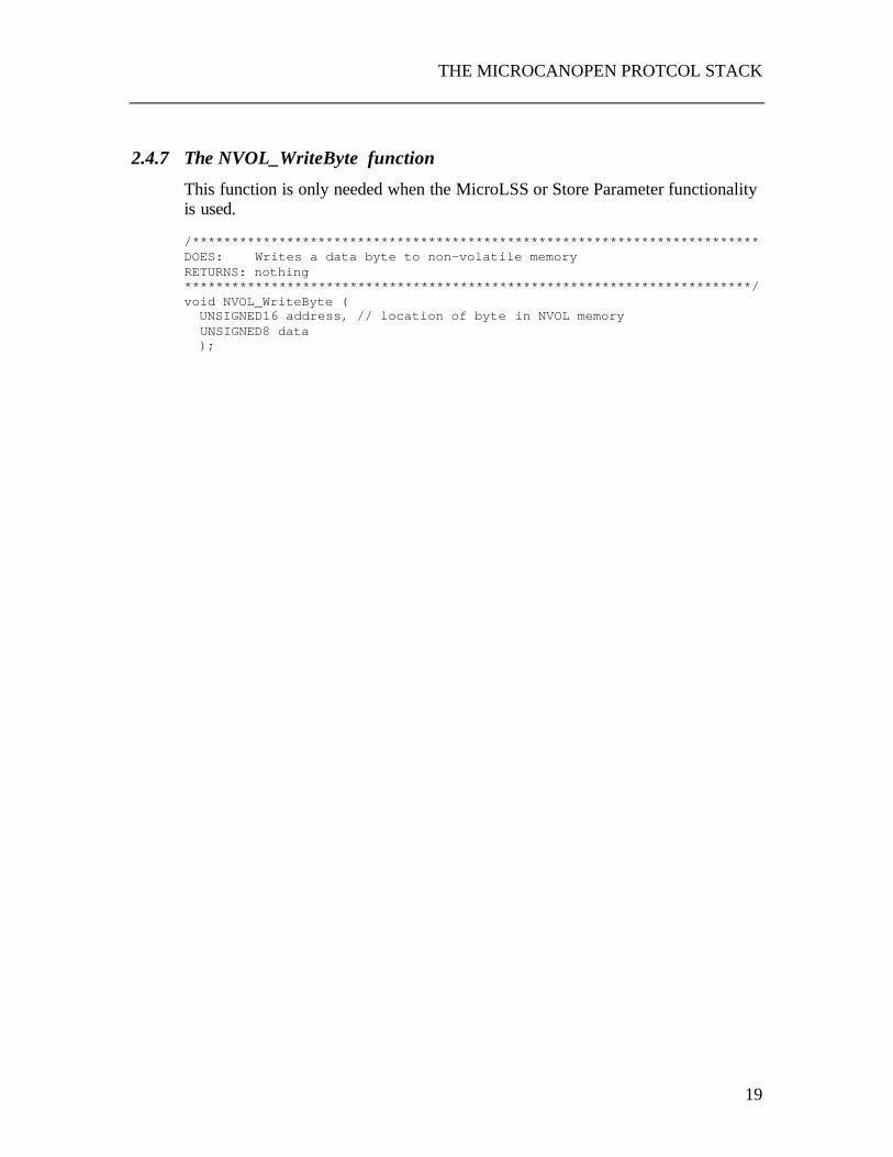
2.4.7 The NVOL_WriteByte function
This function is only needed when the MicroLSS or Store Parameter functionality is used. /************************************************************************ DOES: Writes a data byte to non-volatile memory RETURNS: nothing ************************************************************************/ void NVOL_WriteByte ( UNSIGNED16 address, // location of byte in NVOL memory UNSIGNED8 data );
THE MICROCANOPEN PROTCOL STACK
20
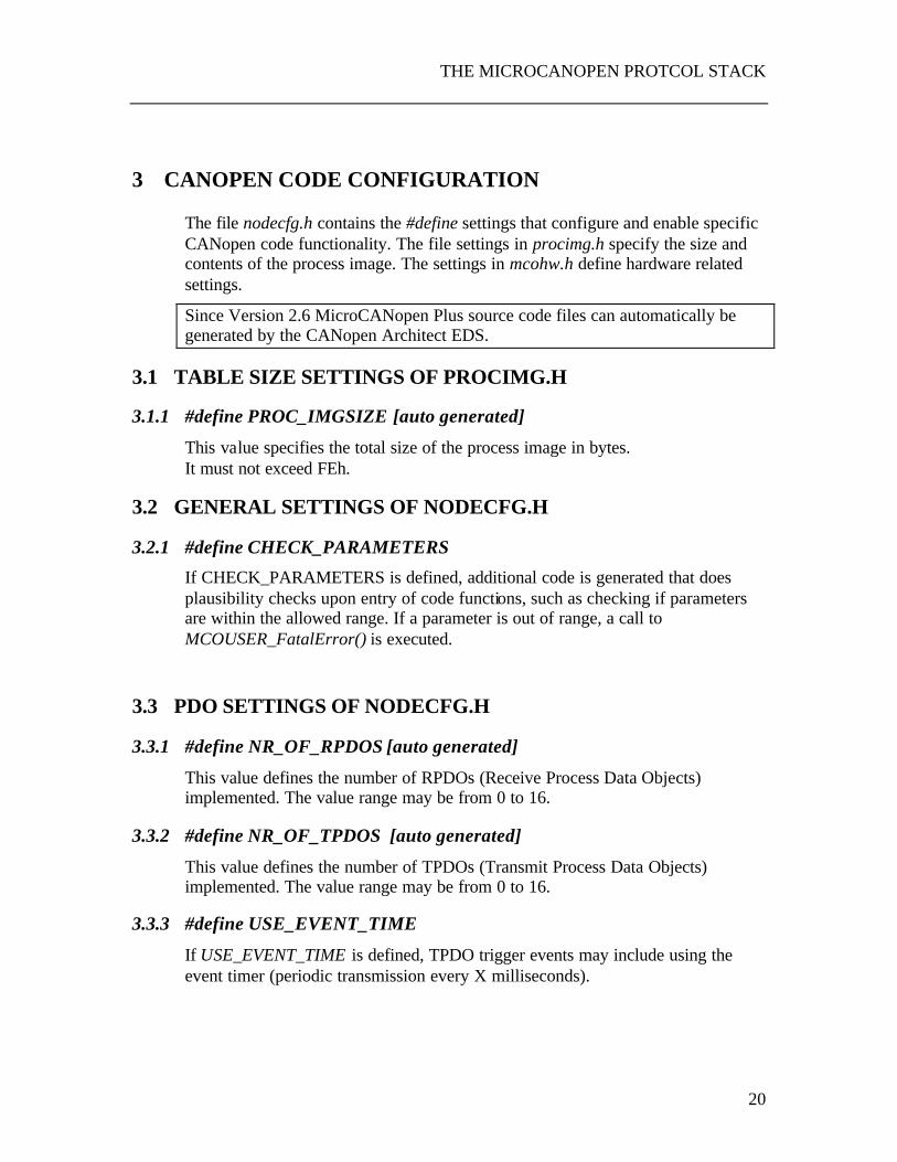
3 CANOPEN CODE CONFIGURATION
The file nodecfg.h contains the #define settings that configure and enable specific CANopen code functionality. The file settings in procimg.h specify the size and contents of the process image. The settings in mcohw.h define hardware related settings.
Since Version 2.6 MicroCANopen Plus source code files can automatically be generated by the CANopen Architect EDS.
3.1 TABLE SIZE SETTINGS OF PROCIMG.H
3.1.1 #define PROC_IMGSIZE [auto generated]
This value specifies the total size of the process image in bytes. It must not exceed FEh.
3.2 GENERAL SETTINGS OF NODECFG.H
3.2.1 #define CHECK_PARAMETERS
If CHECK_PARAMETERS is defined, additional code is generated that does plausibility checks upon entry of code functions, such as checking if parameters are within the allowed range. If a parameter is out of range, a call to MCOUSER_FatalError() is executed.
3.3 PDO SETTINGS OF NODECFG.H
3.3.1 #define NR_OF_RPDOS [auto generated]
This value defines the number of RPDOs (Receive Process Data Objects) implemented. The value range may be from 0 to 16.
3.3.2 #define NR_OF_TPDOS [auto generated]
This value defines the number of TPDOs (Transmit Process Data Objects) implemented. The value range may be from 0 to 16.
3.3.3 #define USE_EVENT_TIME
If USE_EVENT_TIME is defined, TPDO trigger events may include using the event timer (periodic transmission every X milliseconds).
THE MICROCANOPEN PROTCOL STACK
21
3.3.4 #define USE_INHIBIT_TIME
If USE_INHIBIT_TIME is defined, TPDO trigger events may include COS (Change Of State) detection with using the inhibit time.
NOTE: Internally all inhibit times are calculated and used based on a resolution of one millisecond. However, CANopen specifies the inhibit time with a resolution of 100 microseconds. To be CANopen compatible, MicroCANopen automatically does a divide or multiply by 10 when communicating the inhibit time via SDO requests/responses.
3.4 NMT SERVICE SETTINGS OF NODECFG.H
3.4.1 #define AUTOSTART
When AUTOSTART is defined the CANopen device directly switches itself into the operational state after power-on or reset without waiting for a CANopen NMT Master message with an operational command.
3.4.2 #define USE_MICROLSS
This must be defined to 1 if the node should start up in MicroLSS mode. That means it does not start communication, it waits until it gets configured by a MicroLSS Master.
3.4.3 #define DEFAULT_HEARTBEAT [auto generated]
The Object Dictionary entry [1017h,00h] Heartbeat Producer Time is implemented as read-write. The DEFAULT_HEARTBEAT defines the default heartbeat time used by MicroCANopen and is specified in milliseconds.
THE MICROCANOPEN PROTCOL STACK
22
4 USING AUTO-GENERATED SOURCES
The CANopen EDS Editor “CANopen Architect EDS” can generate source files directly usable by MicroCANopen Plus. This chapter summarizes the steps that need to be taken to generate the files and integrate them to MicroCANopen Plus based applications.
The application examples provided with MicroCANopen Plus have their EDS, DCF and auto-generated files stored in the directory “../Utils”
4.1 FILE GENERATION When editing an EDS or DCF with CANopen Architect EDS some extra care should be taken when defining the access type for the Object Dictionary entry.
If the access type of an entry is CONST (constant), then CANopen Architect EDS will not place the entry into the process image but will try to locate it in the non-volatile code space area. This helps to conserve the limited space available for process image data.
As an example, the entries [1008h-100Ah,00h] should be specified as CONST, as these are constant, read-only strings.
For entries using multiple subindexes, the first subindex entry (subindex 0) should also be marked as type CONST. CANopen Architect EDS then places these into the SDO Reply table and not into the process image.
To generate the source files from CANopen Architect EDS simply select the menu “File | Export C Sources Files”. It is recommended to use the default file names suggested when exporting the files.
4.2 FILE INTEGRATION This section describes the information found in each of the generated files and how these files need to be integrated into the application.
4.2.1 PIMG.H
The file pimg.h contains the basic #define settings required by MicroCANopen Plus and all process image offset and size definitions for variables stored in the process image.
This file needs to be included to all the application’s C source files that make accesses to data contained in the process image.
THE MICROCANOPEN PROTCOL STACK
23
4.2.2 INITPDOS.H
The file initpdos.h contains auto-generated calls to the functions MCO_InitRPDO() and MCO_InitTPDO() which initialize the PDOs. The calls are provided as macro INITPDOS_CALLS.
This file should be included to the C source file initializing the CANopen stack and making the call to MCO_Init(). This is typically the file user_xxx.c and the call to MCO_Init() is made in MCOUSER_ResetCommunication().
The recommended usage is:
if (MCO_Init(can_bps,node_id,DEFAULT_HEARTBEAT)) {
//Initialization of PDOs comes from EDS
INITPDOS_CALLS }
4.2.3 ENTRIESANDREPLIES.H
The file entriesandreplies.h contains all auto-generated Object Dictionary entries. These are provided as macros and can directly be included into the data tables defined in the user_xxx.c file.
Usage Example: ...
#include "EDS/entriesandreplies.h"
... // Table with SDO Responses for read requests to OD
UNSIGNED8 MEM_CONST gSDOResponseTable[] = { // Include file generated by CANopen Architect
SDOREPLY_ENTRIES
// End-of-table marker 0xFF, 0xFF, 0xFF, 0xFF, 0xFF, 0xFF, 0xFF, 0xFF
};