Embed Size (px)
Citation preview
IOP PUBLISHING CLASSICAL AND QUANTUM GRAVITY
Class. Quantum Grav. 29 (2012) 184010 (14pp) doi:10.1088/0264-9381/29/18/184010
The MICROSCOPE experiment, ready for thein-orbit test of the equivalence principle
P Touboul1, G Metris2, V Lebat1 and A Robert3
1 Onera, The French Aerospace Lab, F-91123 Palaiseau, France2 Universite de Nice Sophia-Antipolis, CNRS (UMR 6526), Observatoire de la Cote d’Azur,Geoazur, F-06130 Grasse, France3 Cnes, F-31100 Toulouse, France
E-mail: [email protected]
Received 27 January 2012, in final form 27 April 2012Published 15 August 2012Online at stacks.iop.org/CQG/29/184010
AbstractDeviations from standard general relativity are being intensively tested invarious aspects. The MICROSCOPE space mission, which has recently beenapproved to be launched in 2016, aims at testing the universality of free fallwith an accuracy better than 10!15. The instrument has been developed andmost of the sub-systems have been tested to the level required for the detectionof accelerations lower than one tenth of a femto-g. Two concentric test massesare electrostatically levitated inside the same silica structure and controlled onthe same trajectory at better than 0.1 A. Any dissymmetry in the measuredelectrostatic pressures shall be analysed with respect to the Earth’s gravityfield. The nearly 300 kg heavy dedicated satellite is defined to provide a verysteady environment to the experiment and a fine control of its attitude and ofits drag-free motion along the orbit. Both the evaluations of the performanceof the instrument and the satellite demonstrate the expected test accuracy. Thedetailed description of the experiment and the major driving parameters of theinstrument, the satellite and the data processing are provided in this paper.
PACS number: 04.80.Cc
(Some figures may appear in colour only in the online journal)
1. Mission motivations
When developing his new theory of general relativity (GR), Albert Einstein devised threeexperiments to test some of its tiny consequences: the advance of Mercury perihelion, thedeflection of the light by the Sun and the gravitational redshift of light [1]. Two of them werequickly verified: the expected GR deviation on Mercury precession rate, calculated by Einstein,corresponded almost exactly to the observed effect, unexplained by Newtonian gravity laws;Eddington verified during the 1919 total solar eclipse that light from stars was deflecteddue to the Sun mass by an angle corresponding to the GR prediction (which is twice the
0264-9381/12/184010+14$33.00 © 2012 IOP Publishing Ltd Printed in the UK & the USA 1
Class. Quantum Grav. 29 (2012) 184010 P Touboul et al
Newtonian value) [2]. Gravitational redshift was first measured through the Pound–Rebka experiment in the 1960s with the change of gamma-ray wavelength atdifferent al.
Space missions have provided in the last decade more accurate confirmations of theGR predictions. With the precise observation of the LAGEOS satellite orbital plane, takinginto account Earth’s gravity field models from the GRACE mission [3], the Lense–Thirring(or frame dragging) effect has been confirmed with 5% accuracy. Geodetic and frame draggingeffects have been verified with cryogenic gyroscopes on-board GPB, a drag-free satellite[4]. Parameterized post-Newtonian (PPN) formalism helps to compare the accuracy of theperformed tests of GR effects for the weak field [5]. The lunar laser ranging (LLR) leads toan estimation of the PPN parameter ! with an accuracy of 1.1 " 10!4 thanks to the reflectorslaid on the Moon [6]. The tracking of the Cassini spacecraft during its cruise from Jupiter toSaturn including a solar conjunction leads to an accuracy of 2.3 " 10!5 on the " parameter[7]. Other space projects like the ACES mission are in preparation: one of its objectivesis to perform in 2014 the time distribution and comparison between the in-orbit cold atomclock PHARAO, on board the International Space Station, with the ground clocks, and with a10!16 accuracy; this leads to the possibility of redshift measurement up to a relative accuracy of2 " 10!6 [8].
Nevertheless, GR remains a metric theory while other interactions are depicted in thestandard model through a field theory in the rigid spacetime of special relativity. So testing theweak equivalence principle (WEP) not only tests the foundation of GR but also non-metrictheories. Most string theories envisage this EP violation, introducing in particular additionalfields such as the scalar field dilaton for instance [9]. Just as the search for the Higgs bosonsat Cern aims to validate a prediction of the standard model, so the very accurate WEP testenvisaged by the MICROSCOPE space mission may validate GR: both pave the way to newphysics. Both experiments relate to supersymmetry, quantum gravity, or dark energy or darkmatter.
After many years dedicated to the definition of the satellite and the systems, and to thedevelopment of the instrument, the MICROSCOPE mission has now been decided by Cnesand the launch is programmed in 2016. The whole in-orbit test conditions, the experimentalapparatus and the procedures are now defined and specified to reach an accuracy of better than10!15. This is more than two orders of magnitude better than the test performed on groundwith torsion balance pendulum [10]. This requires new techniques for the satellite and thepayload, as well as a fine frequency analysis of the obtained signals to be corrected during thedata processing. This mission also opens the way to even more ambitious ones that shall takeadvantage of the demonstrated approach.
2. Space experiment approach
The direct corollary of the WEP is the universality of free fall (UFF). Successful improvementsand results of the WEP laboratory experiments have been obtained during the two last decadesby the Eot–Wash group with different materials such as Be, Al, Ti, Cu and Si [11]. In the sametime, satellite experiments have been proposed to go further. The cryogenic STEP experimentproposed by Worden was the first one [12]; it has envisaged, more recently, EP test accuracyup to 10!18 with superconductive 2 K accelerometers and four pairs of test masses [13].MICROSCOPE prepares these ambitious future missions performing a similar space test ofUFF, by taking advantage of the existing micro satellite line in Cnes French Agency, but witha payload mass limited to less than 40 kg. The simple experiment of the test of the UFF wouldbe the perfect comparison of the free fall of two masses in the same significant gravity field
2
Class. Quantum Grav. 29 (2012) 184010 P Touboul et al
over a long time span, with very weak perturbations with respect to this field. In practise, onepart is almost achieved in the LLR experiment which compares the Earth and the Moon, freelyfalling in the gravity field of the Sun, in a very quiet environment [14, 15].
The MICROSCOPE aims at doing much better by using the gravity in the vicinity of theEarth which is roughly 1000 times larger than Sun’s gravity and by measuring the positionof two test masses with a much better accuracy than the accuracy of the laser ranging (about10!11 m Hz1/2 for the MICROSCOPE compared to about 1 cm for the LLR). But an idealexperiment could be killed by unwanted effects and it would be unrealistic to mimic the LLRexperiment between two test masses orbiting the Earth for at least two reasons: the possibledifference in free fall would be masked by non-gravitational effects on one hand and by gravitygradient effects on the other.
To overcome these drawbacks, the MICROSCOPE experiment controls the relative motionof the masses, which limits in particular the gravity gradient effects, inside the satelliteforming a shield to the non-gravitational perturbations. More precisely, the electrostatic forcesnecessary to counteract the other accelerations are measured; they keep the two concentriccylindrical test masses on the same orbit. This is the principle of the differential accelerometer.
The difference of the gravitational accelerations between the two masses separated by theoff centring
#
$ is
$!% = !%1 ! !%2 = &12g + [T]#
$,
where g is the gravity acceleration vector and [T] is the gravity gradient tensor; &12 is theEotvos parameter measuring the difference of the ratios between the gravitational mass mg
and the inertial mass mi for bodies 1 and 2:
&12 = 2
mg1
mi1! mg2
mi2mg1
mi1+ mg2
mi2
# mg1
mi1! mg2
mi2
The components of the monopole part of the gravity acceleration—more complete modelsare actually used but this does not modify the forthcoming analysis [16]—are expressed in aquasi-inertial frame, linked to the mean orbital plane and with Y being the orthogonal axis tothe orbital plane, by
gx = a'2[cos ( + 2e cos(2( + )) + O(e)]
gy = 0
gz = !a'2[sin ( + 2e sin(2( + )) + O(e)],
where ' is the orbital angular frequency, a and e are the semi-major axis and the eccentricityof the orbit, ( varies linearly with an angular frequency equal to ' and ) is a constant phase.As e $ 1, the main part of the signal due to an EP violation is a periodic signal of angularfrequency 'EP = ' and amplitude &12a'2. The components of the gravity gradient are asfollows:
Txx = 12'2
!1 + 3 cos(2( ) + e
"! 3
2 cos((!)) + 3 cos(( + )) + 212 cos(3( + ))
#+ O(e)
$
Txy = 0Txz = 1
2'2!!3 sin(2( ) + e
" 32 sin(( ! )) ! 21
2 sin(3( + ))#+ O(e)
$
Tyy = !'2 [1 + 3e cos(( + )) + O(e)]Tyz = 0Tzz = 1
2'2!1 ! 3 cos(2( ) + e
" 32 cos(( ! )) + 3 cos(( + )) ! 21
2 cos(3( + ))#+ O(e)
$.
Note that Txy and Tyz are null due to the fact that the X- and Y-axes are parallel to theorbital plane. Actually, this is valid up to a certain limit which is taken into account, but
3
Class. Quantum Grav. 29 (2012) 184010 P Touboul et al
this simplified formulation is adopted here for clarity of the analysis. As far as e $ 1, thedominant part of the gravity gradient is at DC and at the 2 ' angular frequency; however,there are smaller terms of angular frequency ' = 'EP. The measurement is optimized soas to obtain a larger sensitivity along the axis of the cylinders which will be the X-axis.On this axis, the difference of the gravitational acceleration between the two test masseswill be
$%x = a'2%
& ! 3e4a
($x cos ) + $z sin ))
&cos ( + '2
2$x
+3'2
2($x cos 2( ! $z sin 2( ) + small terms.
The perturbing term 3e4a ($x cos ) + $z sin )) due to the gravity gradient is fully correlated
with the EP signal and must be minimized. To this aim, the orbital eccentricity e and the offcentring must be as small as possible, while the semi-major axis a must be sufficientlylarge. The semi-major axis is also subject to other constraints, one of them being to keepstrong enough the gravity acceleration; it will be about 7100 km for the MICROSCOPE. Bytaking into account the injection errors and the perturbations of the orbit, the eccentricity,that the launcher should reach, is specified less than 5 " 10!3. Under these conditions,each off centring $x and $z should be smaller than 0.1 µm to obtain a perturbing termmuch smaller than the eventual EP violation signal, 10!15 times the field. Taking intoaccount that the off centring between the two test masses is the result of a complexassembly, the specification of 0.1 µm is not reachable directly, even with very sophisticatedmanufacturing procedures and accurate electronics. The off centrings $x and $z are expectedto be less than 20 µm after the instrument manufacturing and integration. So they shallbe estimated in flight with 0.1 µm accuracy, thanks to the large gravity gradient signal ofamplitude 3'2
2a $ at the angular frequency 2'. Then, their effects will be corrected in theground data processing with an accurate Earth’s gravity field model [16]. This requires theknowledge of
• the absolute dating of the measurements with an accuracy of 50 ms,• the satellite position with an accuracy of 7 m at the f EP frequency and• the instrument pointing with accuracies from 3 µrd to 2.5 mrd depending on the frequency.
The first two specifications are not very stringent considering the standard state of the art,but the third is challenging and has required the development of specific procedures including ahybridization between the angular measurements delivered by the star sensors and the angularaccelerations measured by the on-board accelerometers.
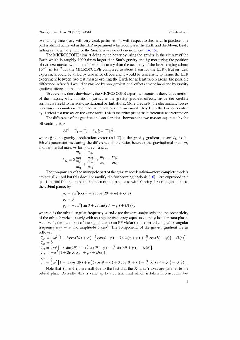
In the previous paragraphs, we have considered the satellite and the test masses inside, withno rotation with respect to the quasi-inertial frame. A rotation around the Y-axis, keeping Xand Z parallel to the orbital plane, can also be considered with a constant spin rate (seefigure 1). Then, the projected gravity acceleration varies in the instrument frame witha frequency f EP = f orb + f spin. The gravity gradient has also a modified spectralrepresentation and has no longer a contribution at f EP frequency. The spinning modehas other advantages like, for instance, reduced thermal perturbations at f EP frequency,larger than f orb. Nevertheless, more stringent requirements on the angular stability mustbe met in the spinning mode than in the quasi-inertial mode. To take advantage ofthe different configurations, MICROSCOPE will operate sequentially either in the quasi-inertial mode or in the spinning mode with two different frequencies, f spin, so that3 f orb < f spin < 5 f orb.
4
Class. Quantum Grav. 29 (2012) 184010 P Touboul et al
EP test Axis
)iT( 2 lairetaM )tP( 1 lairetaM
Figure 1. Configuration of the experiment: the Sun is in the direction normal to the orbital plane andthe satellite rotates about this normal axis; Earth’s gravity is modulated in the instrument referenceframe (in black) by this rotation; the EP test is performed at 1.7 " 10!3 Hz orbital frequency insatellite inertial pointing and at about 10!3 Hz when the satellite is spinning.
For the success of the experiment, the test masses must react in the same way to the samesource of gravity in the absence of EP violation. As far as the Earth’s gravity is concerned,the test masses can be considered as point masses due to the large distance from the sourceand the centring condition is sufficient. The local gravity due to the satellite is mainly at DCand is thus uncorrelated with the EP signal, but care is taken for small variations at f EP dueto thermo-elastic behaviour of the satellite and of the instrument structure. The effects can bereduced to an acceptable level when the cylindrical masses behave like homogeneous spheresup to the second order of the momentums of inertia (i.e. the matrix of inertia is proportionalto the identity matrix). This condition also allows reducing the gravity torque acting on themasses which are used as references to measure the angular acceleration of the satellite. Theapplied electrostatic torques, used to counteract, are then quite proportional to the angularacceleration of the satellite.
The MICROSCOPE encloses two differential accelerometers, 171 mm apart along theY-axis. One differential accelerometer will compare the free fall of two test masses made of thesame material. This provides a very strong check of the experiment, allowing the estimationof the part of the signal which is due to experimental limitations and systematic errors. Thesecond differential accelerometer will compare the free fall of a test mass made in platinumand titanium. The choice of these two materials is the result of a trade-off between the scientificinterests regarding the EP test, theoretical properties [17], macroscopic properties (concerningmagnetic susceptibility, chemical stability, off gassing, thermal expansion, conductivity, etc)and manufacturing compliance.
The MICROSCOPE experiment requires at the same level the best accuracy and thecontrol of the exactitude of the results. That is why many sessions are dedicated to the controlof the satellite, the verification of the instrument operation and the sensors calibration. Byfinely controlling the satellite cinematic motion, calibrated acceleration field can be applied tothe masses and observe by the sensors [18]. In the same spirit, a balance between performingmultiple sessions dedicated to the EP test under various conditions (various spin rates, variouspositions of the test masses, etc) and having a few longer sessions in order to improve thesignal to noise ratio has been established. The adopted trade-off remains on different sessionsof 120 orbital periods. This is long enough to obtain the Eotvos parameter target exactitude
5
Class. Quantum Grav. 29 (2012) 184010 P Touboul et al
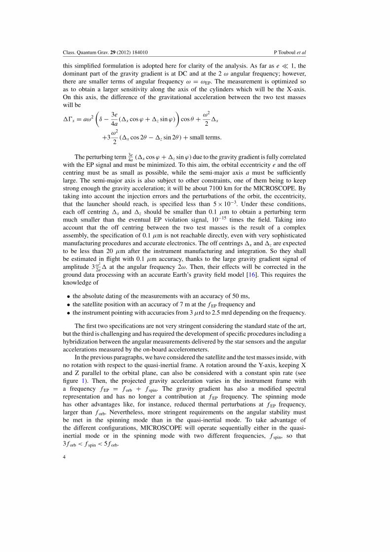
Figure 2. T-SAGE gold-coated tight housings including two concentric inertial sensors (left);cutaway view of the concentric sensors with the two test masses—in violet—surrounded each bytwo silica electrode cylinders—in red—(right).
of 10!15 in inertial mode and even better in rotating mode, by reducing the stochastic errorwith respect to the systematic evaluated one. This is also short enough to have time for manysessions with different experimental conditions.
3. The experimental technique
The electrostatic differential accelerometer, called twin space accelerometer for gravitationexperiment (T-SAGE), is derived from previous developed instrument carried on board theGRACE [19] and GOCE satellites [20]. The MICROSCOPE payload case can only embark twoidentical instruments whose mechanical cores are fixed on the same rigid interface structure(see figure 2). Each accelerometer is composed of two concentric inertial sensors integrating,respectively, the inner and the outer test masses.
The cylindrical test masses are made, respectively, of platinum rhodium and titaniumalloys for the first accelerometer and only platinum rhodium for the second one which isa reference instrument to calibrate the systematic and stochastic errors and the limitationsof the experiment procedures. The test is then based on a double difference, dissymmetryof actuations on the masses of different composition and difference with the reference testmasses made of the same material. Cyclic conditions on the mass composition were selectedfor other missions considering a larger payload with four pairs of masses and three differentmaterials [21].
Identical test mass shapes and not mass values have been chosen in the design becausethe operation of the instrument is based on capacitive position sensing and electrostaticactuation; both are only dependent on the geometry of the configuration of perfect electrostaticconductors. Each test mass is servo-controlled motionless with respect to the instrument frame,so the mass value is only a loop parameter which does not fix directly the instrument responselike in passive mass–spring devices.
The masses of the qualification model (QM), as well as of the flight models (FMs), havebeen produced by PTB in Germany, requiring dedicated machining processes to reach theabsolute sizes of the geometry with an overall defect of less than 3 µm (leading to less than7 " 10!4 relative dissymmetry of momentum of inertia). The conicity is less than 3.5 " 10!5 rdfor the smaller mass and 2 " 10!5 rd for the larger one, limiting the coupling between theradial motion control and the axial one, on which the EP test is performed: moreover, radial
6
Class. Quantum Grav. 29 (2012) 184010 P Touboul et al
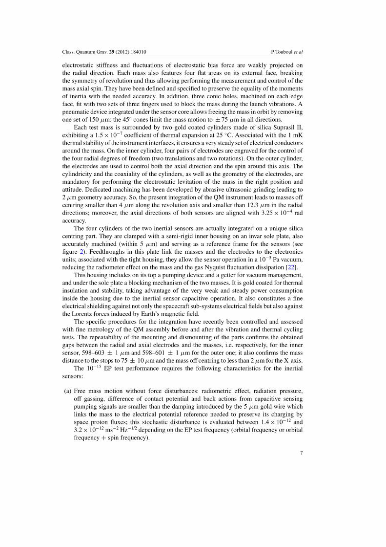
electrostatic stiffness and fluctuations of electrostatic bias force are weakly projected onthe radial direction. Each mass also features four flat areas on its external face, breakingthe symmetry of revolution and thus allowing performing the measurement and control of themass axial spin. They have been defined and specified to preserve the equality of the momentsof inertia with the needed accuracy. In addition, three conic holes, machined on each edgeface, fit with two sets of three fingers used to block the mass during the launch vibrations. Apneumatic device integrated under the sensor core allows freeing the mass in orbit by removingone set of 150 µm: the 45% cones limit the mass motion to ± 75 µm in all directions.
Each test mass is surrounded by two gold coated cylinders made of silica Suprasil II,exhibiting a 1.5 " 10!7 coefficient of thermal expansion at 25 %C. Associated with the 1 mKthermal stability of the instrument interfaces, it ensures a very steady set of electrical conductorsaround the mass. On the inner cylinder, four pairs of electrodes are engraved for the control ofthe four radial degrees of freedom (two translations and two rotations). On the outer cylinder,the electrodes are used to control both the axial direction and the spin around this axis. Thecylindricity and the coaxiality of the cylinders, as well as the geometry of the electrodes, aremandatory for performing the electrostatic levitation of the mass in the right position andattitude. Dedicated machining has been developed by abrasive ultrasonic grinding leading to2 µm geometry accuracy. So, the present integration of the QM instrument leads to masses offcentring smaller than 4 µm along the revolution axis and smaller than 12.3 µm in the radialdirections; moreover, the axial directions of both sensors are aligned with 3.25 " 10!4 radaccuracy.
The four cylinders of the two inertial sensors are actually integrated on a unique silicacentring part. They are clamped with a semi-rigid inner housing on an invar sole plate, alsoaccurately machined (within 5 µm) and serving as a reference frame for the sensors (seefigure 2). Feedthroughs in this plate link the masses and the electrodes to the electronicsunits; associated with the tight housing, they allow the sensor operation in a 10!5 Pa vacuum,reducing the radiometer effect on the mass and the gas Nyquist fluctuation dissipation [22].
This housing includes on its top a pumping device and a getter for vacuum management,and under the sole plate a blocking mechanism of the two masses. It is gold coated for thermalinsulation and stability, taking advantage of the very weak and steady power consumptioninside the housing due to the inertial sensor capacitive operation. It also constitutes a fineelectrical shielding against not only the spacecraft sub-systems electrical fields but also againstthe Lorentz forces induced by Earth’s magnetic field.
The specific procedures for the integration have recently been controlled and assessedwith fine metrology of the QM assembly before and after the vibration and thermal cyclingtests. The repeatability of the mounting and dismounting of the parts confirms the obtainedgaps between the radial and axial electrodes and the masses, i.e. respectively, for the innersensor, 598–603 ± 1 µm and 598–601 ± 1 µm for the outer one; it also confirms the massdistance to the stops to 75 ± 10 µm and the mass off centring to less than 2 µm for the X-axis.
The 10!15 EP test performance requires the following characteristics for the inertialsensors:
(a) Free mass motion without force disturbances: radiometric effect, radiation pressure,off gassing, difference of contact potential and back actions from capacitive sensingpumping signals are smaller than the damping introduced by the 5 µm gold wire whichlinks the mass to the electrical potential reference needed to preserve its charging byspace proton fluxes; this stochastic disturbance is evaluated between 1.4 " 10!12 and3.2 " 10!12 ms!2 Hz!1/2 depending on the EP test frequency (orbital frequency or orbitalfrequency + spin frequency).
7
Class. Quantum Grav. 29 (2012) 184010 P Touboul et al
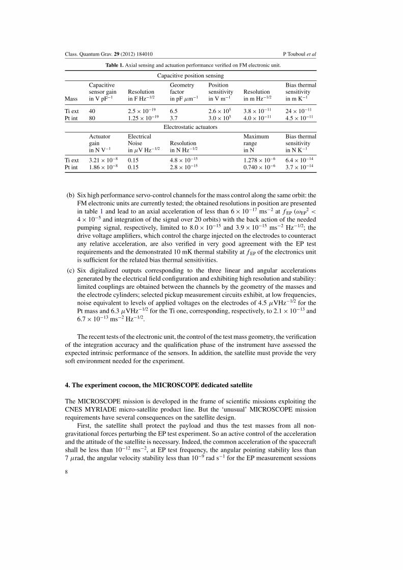
Table 1. Axial sensing and actuation performance verified on FM electronic unit.
Capacitive position sensing
Capacitive Geometry Position Bias thermalsensor gain Resolution factor sensitivity Resolution sensitivity
Mass in V pF!1 in F Hz!1/2 in pF µm!1 in V m!1 in m Hz!1/2 in m K!1
Ti ext 40 2.5 " 10!19 6.5 2.6 " 105 3.8 " 10!11 24 " 10!11
Pt int 80 1.25 " 10!19 3.7 3.0 " 105 4.0 " 10!11 4.5 " 10!11
Electrostatic actuators
Actuator Electrical Maximum Bias thermalgain Noise Resolution range sensitivityin N V!1 in µV Hz!1/2 in N Hz!1/2 in N in N K!1
Ti ext 3.21 " 10!8 0.15 4.8 " 10!15 1.278 " 10!6 6.4 " 10!14
Pt int 1.86 " 10!8 0.15 2.8 " 10!15 0.740 " 10!6 3.7 " 10!14
(b) Six high performance servo-control channels for the mass control along the same orbit: theFM electronic units are currently tested; the obtained resolutions in position are presentedin table 1 and lead to an axial acceleration of less than 6 " 10!17 ms!2 at f EP ('EP
2 <
4 " 10!5 and integration of the signal over 20 orbits) with the back action of the neededpumping signal, respectively, limited to 8.0 " 10!15 and 3.9 " 10!15 ms!2 Hz!1/2; thedrive voltage amplifiers, which control the charge injected on the electrodes to counteractany relative acceleration, are also verified in very good agreement with the EP testrequirements and the demonstrated 10 mK thermal stability at f EP of the electronics unitis sufficient for the related bias thermal sensitivities.
(c) Six digitalized outputs corresponding to the three linear and angular accelerationsgenerated by the electrical field configuration and exhibiting high resolution and stability:limited couplings are obtained between the channels by the geometry of the masses andthe electrode cylinders; selected pickup measurement circuits exhibit, at low frequencies,noise equivalent to levels of applied voltages on the electrodes of 4.5 µVHz!1/2 for thePt mass and 6.3 µVHz!1/2 for the Ti one, corresponding, respectively, to 2.1 " 10!13 and6.7 " 10!13 ms!2 Hz!1/2.
The recent tests of the electronic unit, the control of the test mass geometry, the verificationof the integration accuracy and the qualification phase of the instrument have assessed theexpected intrinsic performance of the sensors. In addition, the satellite must provide the verysoft environment needed for the experiment.
4. The experiment cocoon, the MICROSCOPE dedicated satellite
The MICROSCOPE mission is developed in the frame of scientific missions exploiting theCNES MYRIADE micro-satellite product line. But the ‘unusual’ MICROSCOPE missionrequirements have several consequences on the satellite design.
First, the satellite shall protect the payload and thus the test masses from all non-gravitational forces perturbing the EP test experiment. So an active control of the accelerationand the attitude of the satellite is necessary. Indeed, the common acceleration of the spacecraftshall be less than 10!12 ms!2, at EP test frequency, the angular pointing stability less than7 µrad, the angular velocity stability less than 10!9 rad s!1 for the EP measurement sessions
8
Class. Quantum Grav. 29 (2012) 184010 P Touboul et al
CGPSAttitude
control laws
Thrusterselection logic
Estimation filter
Star Tracker
6-axes accelerometer
attitude
!
"
accelerations
Disturbing forces and
torques
++T
CF
CGPSCF
Fcom
...
iais_ang_ACCBˆ
sat
satQ
!
Attitude measurement
Linear acceleration measurement m"
Angular accelerationmeasurement
m!
Estimated :
MCA Software (4Hz)
Qcc -
+
( )c
Fsp1:8
Tcom
Satellite Dynamic
Accelerationscontrol laws
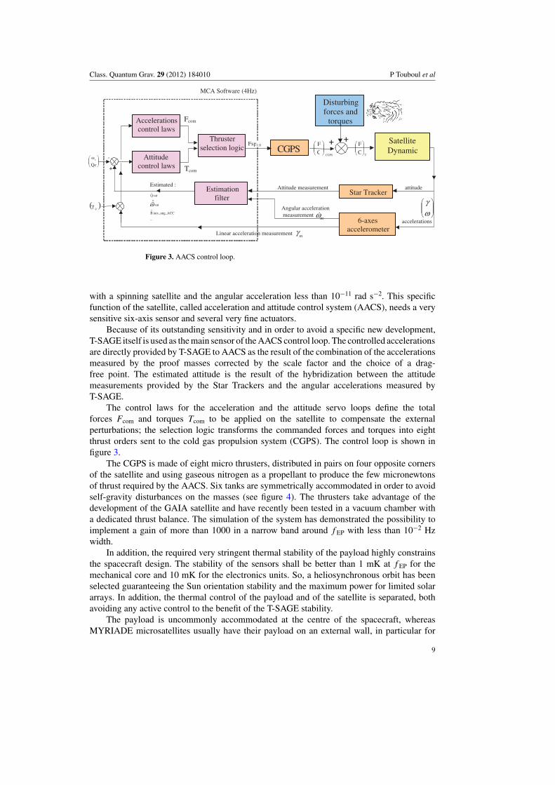
Figure 3. AACS control loop.
with a spinning satellite and the angular acceleration less than 10!11 rad s!2. This specificfunction of the satellite, called acceleration and attitude control system (AACS), needs a verysensitive six-axis sensor and several very fine actuators.
Because of its outstanding sensitivity and in order to avoid a specific new development,T-SAGE itself is used as the main sensor of the AACS control loop. The controlled accelerationsare directly provided by T-SAGE to AACS as the result of the combination of the accelerationsmeasured by the proof masses corrected by the scale factor and the choice of a drag-free point. The estimated attitude is the result of the hybridization between the attitudemeasurements provided by the Star Trackers and the angular accelerations measured byT-SAGE.
The control laws for the acceleration and the attitude servo loops define the totalforces Fcom and torques Tcom to be applied on the satellite to compensate the externalperturbations; the selection logic transforms the commanded forces and torques into eightthrust orders sent to the cold gas propulsion system (CGPS). The control loop is shown infigure 3.
The CGPS is made of eight micro thrusters, distributed in pairs on four opposite cornersof the satellite and using gaseous nitrogen as a propellant to produce the few micronewtonsof thrust required by the AACS. Six tanks are symmetrically accommodated in order to avoidself-gravity disturbances on the masses (see figure 4). The thrusters take advantage of thedevelopment of the GAIA satellite and have recently been tested in a vacuum chamber witha dedicated thrust balance. The simulation of the system has demonstrated the possibility toimplement a gain of more than 1000 in a narrow band around f EP with less than 10!2 Hzwidth.
In addition, the required very stringent thermal stability of the payload highly constrainsthe spacecraft design. The stability of the sensors shall be better than 1 mK at f EP for themechanical core and 10 mK for the electronics units. So, a heliosynchronous orbit has beenselected guaranteeing the Sun orientation stability and the maximum power for limited solararrays. In addition, the thermal control of the payload and of the satellite is separated, bothavoiding any active control to the benefit of the T-SAGE stability.
The payload is uncommonly accommodated at the centre of the spacecraft, whereasMYRIADE microsatellites usually have their payload on an external wall, in particular for
9

Class. Quantum Grav. 29 (2012) 184010 P Touboul et al
Figure 4. MICROSCOPE satellite internal layout (left) and external layout (right); note that theglobal navigation satellite system receiver is only optional.
optical and radar missions. The same internal case supports on its top the sensor housings andat the middle the electronics units. It also includes the thermal control hardware and providesthe centring of the proof masses with respect to the satellite spin axis. It exhibits a very highmechanical stability during the entire mission. This guarantees the thermal operating range of10–45 %C, taking into account the 6 W power dissipation of each electronic unit. Besides thethermal stability, it also includes a magnetic shielding for the masses. The thermal stability ofeach payload unit has been tested and has confirmed the two-stage insulation. The first stagesupports the electronic units, thermally linked to the outer radiator, and insulated itself fromthe satellite structure by six titanium alloy blades. As shown in figure 1, this anti-Sun radiatoris protected from Earth’s albedo by a cone so that the thermal conditions do not vary. Thesecond stage which supports the two housings and the magnetic shielding is mechanicallylinked and thermally insulated from the first stage by six titanium alloy blades.
Apart from the thermal effects, three categories of internal micro-perturbations have beenconsidered and reduced in the satellite design: mechanical, gravitational and magnetic. Anymass displacement inside the spacecraft has been suppressed except the gas consumption andits thermo-elastic effects have been finely analysed. These modifications of the distribution ofmass may also change the self-gravity gradients but these effects have been checked and arevery weak at f EP. The electrical activity of the circuits and the equipments of the satellite maychange the internal magnetic field but the instrument shielding provides margins against thesepotential effects.
Some of these perturbations may be much stronger during the eclipse season (three monthsa year) at the transition of the satellite into Earth’s shadow, inducing several phenomena: suddensolar pressure variation, MLI thermo elastic clank, non-regulated bus voltage variation, etc.For these reasons, the EP test is not performed during this period which may be used on theopposite to characterize the payload sensitivities to these increased perturbations.
5. Experimental and mission status
Recent decisions in Cnes have started the production of the satellite from the detailed definitionestablished in very strong relationships with the instrument and the test procedures. The satelliteis actually in a certain way the Einstein falling elevator in which the MICROSCOPE experiment
10
Class. Quantum Grav. 29 (2012) 184010 P Touboul et al
Table 2. Evaluation of the MICROSCOPE space experiment performance: four major sources.
Stochastic error sources In ms!2 Hz1/2 Systematic error sources at f EP In ms!2
Accelerometer noise 1.36 " 10!12 Pointing stability 4.8 " 10!16
Centrifugal acceleration 0.30 " 10!12 Magnetic field 4.0 " 10!16
Angular acceleration 0.20 " 10!12 Sensor thermal variations 3.5 " 10!16
Sensor thermal gradient 0.19 " 10!12 Drag-free residual acceleration 3.3 " 10!16
is performed and the EP test accuracy depends not only on the instrument performancepresented in section 3 but also on both the ways the common disturbances are rejectedin the inertial sensor output difference and the sufficient limited levels of the differentialdisturbances.
The satellite angular and centrifugal accelerations have a limited impact in the observeddifference of the measured accelerations thanks to both the satellite AACS and the masscentring. The evolution of the satellite attitude has been simulated taking into account theaccuracy of the star sensor quaternion and of the angular accelerations delivered by thepayload itself, as well as the resolution of the cold gas thrusters. These thrusters havebeen recently tested and qualified successfully for the GAIA mission satellite. As shown intable 2, the stochastic variations should not affect the test when compared with the instrumentintrinsic noise. Systematic error may appear in the pointing stability of the satellite (necessaryto reduce and correct the gravity gradient), because of artefact signals delivered by the pixelsof the star sensor and of the thermo-elastic deformation of the satellite structure which carriesthe star sensors and the accelerometers. The evaluation of the differential acceleration due tothe pointing fluctuations is provided in table 2.
The residual linear acceleration of the satellite on which both differential accelerometersare fixed is servo controlled through the drag compensation loop of the satellite. An accelerationresidue may be applied to both masses and a difference of sensitivity or alignment of the twoinertial sensors may introduce differences in the measured accelerations which depend on thematching accuracy of these instrument parameters.
Other differential accelerations may be applied on the test masses because of theirdifference of magnetic susceptibility and volume when considering the residue of the fieldand its gradient inside the payload shielding. Fluctuations of the temperature of the sensor andits thermal gradients modify, respectively, the gold wire stiffness and the radiometer and theradiation pressures applied on the test masses.
The corresponding contributions of the four major errors, depicted above and which limitthe EP test accuracy, are provided in the case of a spinning satellite in table 2. In fact, hundredsof contributions at instrument or satellite levels have been evaluated from the specificationsor the control measurements. They have been presented to the Cnes review committee andthe specifications are followed in the present development phase of the satellite. They willbe considered when in orbit according to the instrument and the experiment environmentknowledge.
The quadratic sum of the stochastic and systematic errors leads presently to1.5 " 10!12 ms!2 Hz!1/2, dominated by the accelerometer noise and 1.1 " 10!15 ms!2 atf EP corresponding to many sources at similar levels: a quadratic sum is performed becausethe worst case values of numerous independent systematic sources (and without correlatedphase) are statistically considered. This is compatible to the 10!15 EP test accuracy and evenbetter, considering the 8 ms!2 level of gravity at 720 km altitude. Because the experiment willbe performed several times with steady conditions over a minimum of 20 orbits, predominant
11
Class. Quantum Grav. 29 (2012) 184010 P Touboul et al
stochastic errors should be reduced and several 10!16 accuracies obtained. Errors are largerwhen considering the inertial pointing of the satellite with lower f EP, equal to the orbitalfrequency: thermodynamic noise is increased, thermal filtering is reduced, drift is larger,Earth’s gravity gradient more disturbing. Measurement sessions of 120 orbits have been thusconsidered and 10!15 EP test accuracy should be obtained.
The GOCE satellite, launched in March 2009 at an altitude of 260 km, integratessix space electrostatic accelerometers which constitute the sensors of the on-board gravitygradiometer [23]. These instruments have been developed in our laboratory with the sameconcept and technology than the MICROSCOPE instrument, except the cylindrical concentricconfiguration. They have demonstrated, in orbit for now more than three years, that they canexhibit residual noise lower than 3.1 " 10!12 ms!2 Hz!1/2. Many in-orbit tests corroboratethe instrument models and error budgets. Concerning the stochastic errors, both instrumentsare in the same range. Concerning the frequency bandwidth, the GOCE accelerometer ismore demanding because of a needed performance between 0.005 and 0.1 Hz while theMICROSCOPE performance must be reached at a very narrow frequency bandwidth aroundf EP. Conversely, the MICROSCOPE experiment is much more demanding for the long-termstability of the instrument environment (thermal, magnetic, accelerometric, etc) that must beinsured by the satellite.
The ground data processing which we have developed has already considered the neededfrequency analysis and the limitation introduced by the limited duration of the measurementsessions. In addition, we have anticipated possible small lacks in the data series which mayappear because of some difficulties of the satellite-ground telemeasure system. They couldslightly modify the spectral characteristics of the signal. Furthermore, in-orbit calibration ofthe instrument will be performed by shaking the satellite along and about selected axes tocompare the inertial sensor responses. A similar approach has been performed successfully inthe GOCE mission. Corrections of the measurements have to be performed to compensate thedifferences of the response. So, the Onera-OCA’s scientific mission centre will not only post-validate the data before the distribution and the archiving, but will also verify, in a week delay,the behaviour of the experiment so that the mission scenario can be modified if necessary.The 1.5-year mission duration, limited by the embarked quantity of propulsion gas, must beexploited very efficiently.
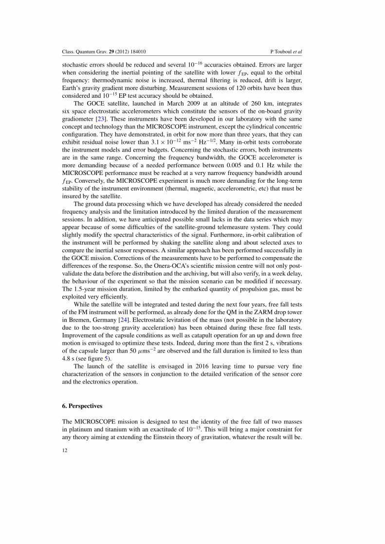
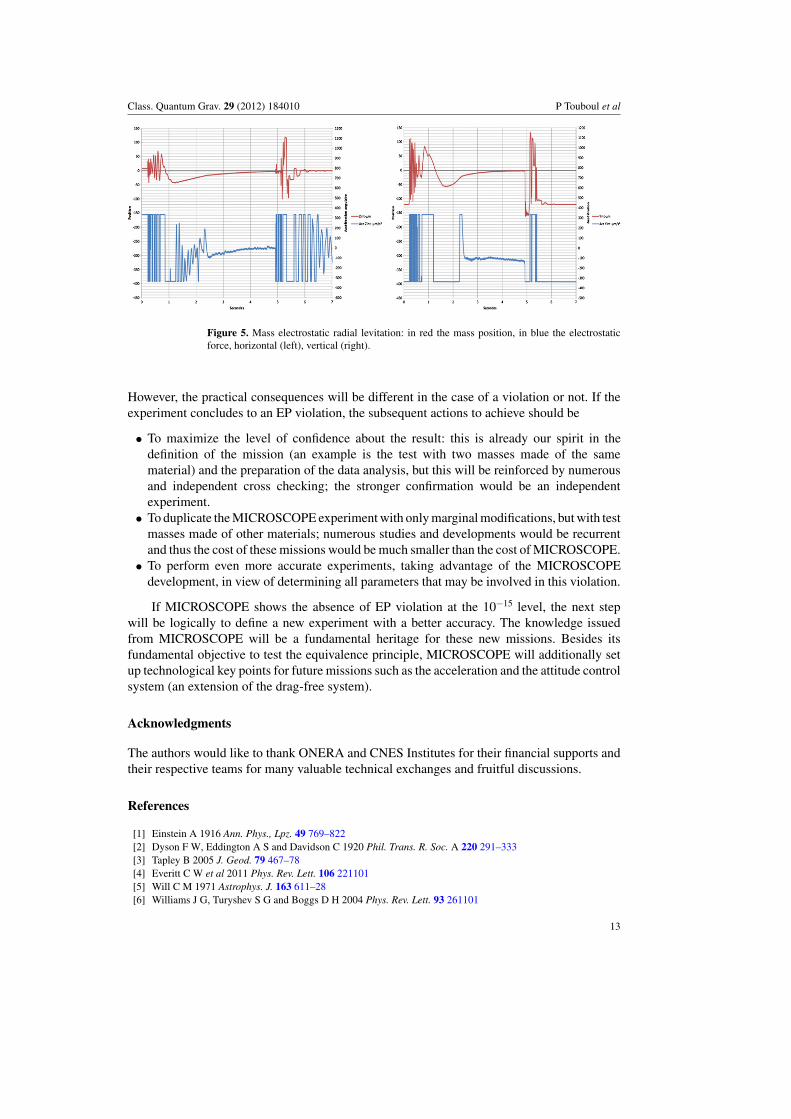
While the satellite will be integrated and tested during the next four years, free fall testsof the FM instrument will be performed, as already done for the QM in the ZARM drop towerin Bremen, Germany [24]. Electrostatic levitation of the mass (not possible in the laboratorydue to the too-strong gravity acceleration) has been obtained during these free fall tests.Improvement of the capsule conditions as well as catapult operation for an up and down freemotion is envisaged to optimize these tests. Indeed, during more than the first 2 s, vibrationsof the capsule larger than 50 µms!2 are observed and the fall duration is limited to less than4.8 s (see figure 5).
The launch of the satellite is envisaged in 2016 leaving time to pursue very finecharacterization of the sensors in conjunction to the detailed verification of the sensor coreand the electronics operation.
6. Perspectives
The MICROSCOPE mission is designed to test the identity of the free fall of two massesin platinum and titanium with an exactitude of 10!15. This will bring a major constraint forany theory aiming at extending the Einstein theory of gravitation, whatever the result will be.
12
Class. Quantum Grav. 29 (2012) 184010 P Touboul et al
Figure 5. Mass electrostatic radial levitation: in red the mass position, in blue the electrostaticforce, horizontal (left), vertical (right).
However, the practical consequences will be different in the case of a violation or not. If theexperiment concludes to an EP violation, the subsequent actions to achieve should be
• To maximize the level of confidence about the result: this is already our spirit in thedefinition of the mission (an example is the test with two masses made of the samematerial) and the preparation of the data analysis, but this will be reinforced by numerousand independent cross checking; the stronger confirmation would be an independentexperiment.
• To duplicate the MICROSCOPE experiment with only marginal modifications, but with testmasses made of other materials; numerous studies and developments would be recurrentand thus the cost of these missions would be much smaller than the cost of MICROSCOPE.
• To perform even more accurate experiments, taking advantage of the MICROSCOPEdevelopment, in view of determining all parameters that may be involved in this violation.
If MICROSCOPE shows the absence of EP violation at the 10!15 level, the next stepwill be logically to define a new experiment with a better accuracy. The knowledge issuedfrom MICROSCOPE will be a fundamental heritage for these new missions. Besides itsfundamental objective to test the equivalence principle, MICROSCOPE will additionally setup technological key points for future missions such as the acceleration and the attitude controlsystem (an extension of the drag-free system).
Acknowledgments
The authors would like to thank ONERA and CNES Institutes for their financial supports andtheir respective teams for many valuable technical exchanges and fruitful discussions.
References
[1] Einstein A 1916 Ann. Phys., Lpz. 49 769–822[2] Dyson F W, Eddington A S and Davidson C 1920 Phil. Trans. R. Soc. A 220 291–333[3] Tapley B 2005 J. Geod. 79 467–78[4] Everitt C W et al 2011 Phys. Rev. Lett. 106 221101[5] Will C M 1971 Astrophys. J. 163 611–28[6] Williams J G, Turyshev S G and Boggs D H 2004 Phys. Rev. Lett. 93 261101
13
Class. Quantum Grav. 29 (2012) 184010 P Touboul et al
[7] Bertotti B, Iess L and Tortora P 2003 Nature 425 374–6[8] Cacciapuoti L and Salomon C 2009 Eur. Phys. J. 172 57–68[9] Damour T and Donoghue J F 2010 Class. Quantum Grav. 27 202001
[10] Schlamminger S, Choi K Y, Wagner T A, Gundlach J H and Adelberger E G 2008 Phys. Rev. Lett. 100 041101[11] Adelberger E G, Gundlach J H, Heckel B R, Hoedl S and Schlamminger S 2009 Part. Nucl. Phys. 62 102[12] Worden P W Jr 1976 PhD Thesis Stanford University[13] Sumner T J 2007 Adv. Space Res. 39 254–8[14] Nordtvedt K 1968 Phys. Rev. 170 1186–7[15] Damour T and Vokrouhlicky D 1996 Phys. Rev. D 53 4177–201[16] Bruinsma S, Lemoine J-M, Biancale R and Vales N 2010 Adv. Space Res 45 587–601[17] Damour T and Blaser J-P 1994 Particle Astrophysics, Atomic Physics and Gravitation ed J Tran Thanh Van,
G Fontaine and E Hinds (Gif-sur-Yvette: Editions Frontieres) pp 433–40[18] Levy A, Touboul P, Rodrigues M, Metris G and Robert A 2010 SF2A ed S Boissier, M Heydari-Malayeri,
R Samadi and D Valls-Gabaud pp 123–6[19] Flury J, Bettadpur S and Tapley B D 2008 Adv. Space Res. 42 1414–23[20] Touboul P, Foulon B, Christophe B and Marque J P 2011 Geodesy for Planet Earth vol 136 ed S Kenyon et al
(Berlin: Springer) pp 215–21[21] Mester J 2001 Class. Quantum Grav. 18 2475–86[22] Touboul P 2010 Space Science Series of ISSI vol 34 ed C W F Everitt et al (New York: Springer) 507–26[23] Floberghagen R, Fehringer M, Lamarre D, Muzi D, Frommknecht B, Steiger C, Pineiro J and da Costa A 2011
J. Geod. 85 749–58[24] Selig H, Dittus H and Lammerzahl C 2010 Microgravity Sci. Technol. 22 539–49
14


![Orbit type: Sun Synchronous Orbit ] Orbit height: …...Orbit type: Sun Synchronous Orbit ] PSLV - C37 Orbit height: 505km Orbit inclination: 97.46 degree Orbit period: 94.72 min ISL](https://img.pdfslide.net/doc/110x75/5f781053e671b364921403bc/orbit-type-sun-synchronous-orbit-orbit-height-orbit-type-sun-synchronous.jpg)