Embed Size (px)
Citation preview

Orlando - The Mode S Beacon Radw System
Air Traffic Control Radar Beacon System
Figure 1 schematically illustrates the opera- tion of the current ATCRBS. The ATCRBS an- tenna, which is typically mounted above the primary-radar antenna, has a fan-beam pattern with a horizontal beam width of 2" to 3". The scan rate is 4.8 s for a sensor used at an airport terminal, and 10 s to 12 s elsewhere. Civil ATCRBS transponders accept two types of inter- rogations. Mode A has an 8-ps PPto-P3 spacing and elicits a 20.3-ps reply that contains one of 4,096 pilot-entered identity codes. Mode C has a 2 1-ps PI-to-P3 spacing and elicits a similar reply that contains the aircraft's barometric altitude referenced to standard atmospheric conditions. The purpose of the P2 pulse is described in the following section.
ATCRBS nansrnit Sidelobe Suppression
At short ranges, an antenna's signal strength may be high enough that transponders are interrogated via leakage through the antenna sidelobes. For control of this phenomenon, air- craft in the antenna-sidelobe regions are pre- vented from replying by a technique known as transmit sidelobe suppression (SLS), illustrated in Fig. 2. In transmit SLS, the P2 pulse of the interrogation is transmitted from an omnidirec- tional antenna at a slightly higher power level than the interrogator power produced by the antenna sidelobes. Transponders are designed to reply only if the received P, pulse is greater than the received P2 pulse. Note that this condi- tion is not satisfied in the antenna-sidelobe regions.
Identification Code
Reply (1,090 MHz) Interrogation (1,030 MHz) - S ? ? S
-1 / :I ILL- J 1-1 J Mode n fl . . .
+-I It------- 20.3 p s 1 Altitude 8 PS
S p2 S Mode n n n . . . -0
k-------- 21 ps ---------+- I I* - 20.3 p s *I
Fig. I-Air Traffic Control Radar Beacon System (ATCRBS).
lhe Lincoln Laboratory Journal, Volume 2. Number 3 (1 989)

Orlando - The Mode S Beacon Radar System
I , Omnidirectional Antenna Pattern P2 1 Directional Antenna Pattern I , p 0 - 1 /
Fig. 2-Sidelobe-suppression (SLS) operation.
ATCRBS Limitations
The current ATCRBS satisfies operational requirements in most airspace. The system, however, has the following limitations in regions of high traffic and sensor densities. ( 1 ) Synchronous garbling (described later). (2) Azimuth inaccuracy (described later). (3) Fruit. Replies received from interroga-
tions by neighboring sensors are called fruit. These unwanted replies are not synchronized with the local sensor's interrogations, and are thus received at random times. The presence of fruit can interfere with the reception of a wanted reply. As a result, high fruit rates can produce a detectable decrease in per- formance. The use of high pulse-repeti- tion frequencies (PRF) for sliding- window detection contributes to this problem. (Sliding-window detection will be discussed in a following section.)
(4) Overinterrogation. In a region containing many sensors, a transponder will receive a high rate of interrogations and SLSs. Consequently, the transponder may be unable to reply when it receives an inter- rogation from the local sensor. As is the case with fruit, the use of high PRFs aggravates overinterrogation.
(5) Aircraft identification. In many regions of the world, the limit of 4,096 different Mode-A codes is insufficient.
Synchronous Garbling of ATCRBS Replies
Synchronous garbling occurs when two ATCRBS aircraft (shown as A and Bin Fig. 3) are within about 3" in azimuth from an ATCRBS radar and when their slant ranges (i.e., their line-of-sight distances from the sensor) differ by less than 1.64 nautical miles (nmi) . Under such conditions, the transmitted interrogation elicits replies from both transponders, and the replies overlap at the receiver. The overlap can lead to missing or incorrectly decoded replies, which results in a loss of information on the control- ler's display. The loss persists until the aircraft change their relative positions. Thus the reply overlap can last for many scans, hence the name synchronous garble. Note that the altitudes of the two aircraft do not have to be close for garbling to occur.
Azimuth Inaccuracy
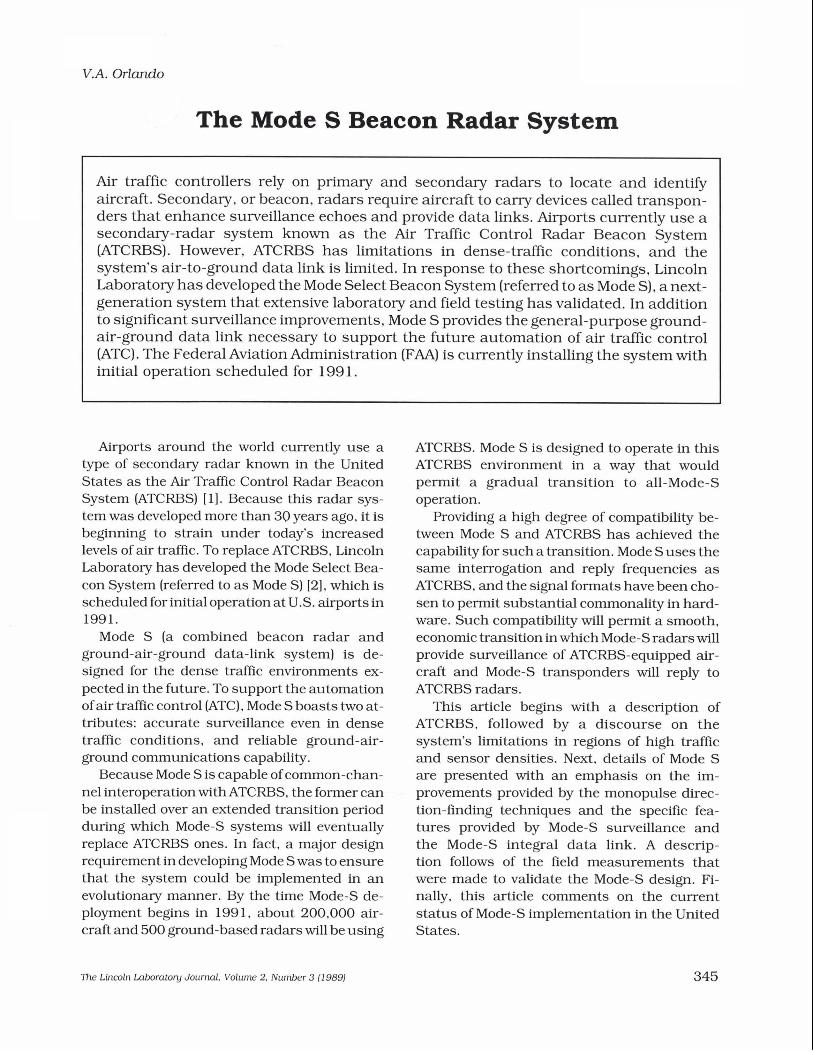
Current ATCRBS sensors in the United States use sliding-window detection (Fig. 4), a technique that determines the azimuth of an aircraft by marking the center of the aircraft's run length. (A run length is a series of transpon- der replies that are observed as the antenna beam of a sensor scans past an aircraft.) A leading-edge detector determines the beginning of a run length by detecting the presence of a minimum of m replies from n reply opportuni- ties. (Following an interrogation, the detector
Interrogation -M nn
Reply rrlllllllll
Fig. 3-Synchronous garbling of A TCRBS replies.
'Ihe Lincoln Laboratory JoumaL Volume 2, Number 3 (1 989)
Orlando - The Mode S Beacon Radar System
Leading-Edge Detection
'CRBS Replies /
Aircraft Azimuth
Trailing-Edge Detection
Characteristics: High Pulse-Repetition Frequency, Susceptible to Azimuth Splits
Fig. 4-Sliding- window beam splitter.
waits a certain time, called the listening interval, for a reply to be issued.) A similar algorithm is used for trailing-edge detection. Once the lead- ing and trailing edges have been determined, the aircraft azimuth is calculated as the center of the run length with an offset to account for the bias that the edge detectors introduce.
To ensure accuracy, a sliding-window detec- tor requires a relatively small interval between successive replies. Typically, a PRF of approxi- mately 400 interrogations/s is used, which produces the 15 or more replies required for sliding-window beam splitting. A disadvantage of such a high PRF, however, is that it can interfere with the operation of neighboring sensors.
Another disadvantage of a sliding-window beam splitter is a susceptibility to azimuth splits, which occur when interference (e.g., from fruit) or blockage from a physical obstruction, such as a building, causes a loss of data in the center of the reply run length. The loss results in the false declaration of a trailing edge followed by a leading edge, which leads to the erroneous declaration that there are two aircraft instead of one. To make matters worse, neither of the two target reports contains the correct azimuth of the one aircraft.
The Monopulse Technique
To address the many limitations of ATCRBS,
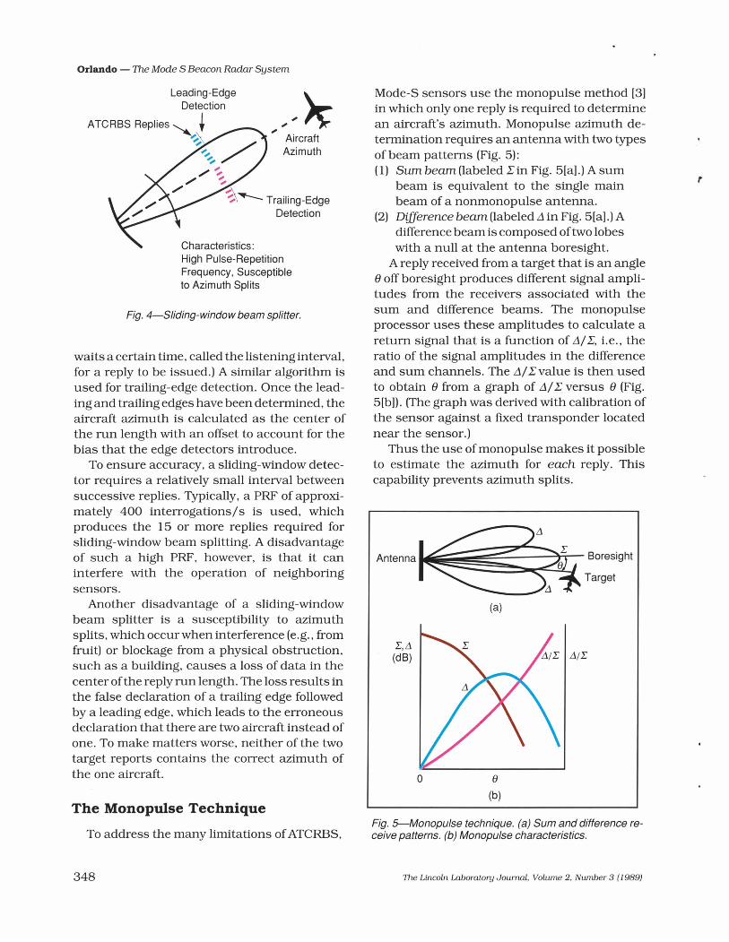
Mode-S sensors use the monopulse method [3] in which only one reply is required to determine an aircraft's azimuth. Monopulse azimuth de- termination requires an antenna with two types of beam patterns (Fig. 5): (1) Sum beam (labeled Z in Fig. 5[a] .) A sum
beam is equivalent to the single main beam of a nonmonopulse antenna.
(2) Dzflerence beam (labeled A in Fig. 5[a] .) A difference beam is composed of two lobes with a null at the antenna boresight.
A reply received from a target that is an angle 8 off boresight produces different signal ampli- tudes from the receivers associated with the sum and difference beams. The monopulse processor uses these amplitudes to calculate a return signal that is a function of A/Z, i.e., the ratio of the signal amplitudes in the difference and sum channels. The A/Zvalue is then used to obtain 8 fi-om a graph of A/Z versus 8 (Fig. 5[b]). (The graph was derived with calibration of the sensor against a fured transponder located near the sensor.)
Thus the use of monopulse makes it possible to estimate the azimuth for each reply. This capability prevents azimuth splits.
Antenna Boresig ht
Target
(a)
z, A (dB)
8
(b)
Fig. 5-Monopulse technique. (a) Sum and difference re- ceive patterns. (b) Monopulse characteristics.
The Lincoln Laborato y Journal, Volume 2, Number 3 ( 1 989)

Orlando - The Mode S Beacon Radar System
ATCRBS Monopulse Azimuth Determination
Monopulse makes surveillance of ATCRBS aircraft at very low interrogation rates possible. In theory, monopulse surveillance can be per- formed with as little as one Mode-A and one Mode-C reply opportunity per scan. In practice, however, additional replies are needed to ensure correct Mode-A and Mode-C code reception and to suppress false alarms. The Mode-S sensor interrogates at a rate sufficient to elicit two replies for each ATCRBS mode within the ATCRBS antenna's 3-dB beamwidth of 2.4". This capability leads to a PRF of approximately 100 pulses/s, which is about one-quarter of the current interrogation rate of ATCRBS.
Monopulse Degarbling of ATCRBS Replies
A second benefit of monopulse is that it
enables the degarbling of ATCRBS replies [4]. Figure 6 shows two aircraft (labeled A and B) that are simultaneously in the main beam of and near the same slant range from a radar. The received signal data show an interleaved mix of code pulses from the two aircraft. Referencing the monopulse data enables the pulses to be identified easily.
In the example of Fig. 6, the pulses do not overlap; hence they could have been sorted into the correct replies if the pulse-timing data were used. However, in instances of pulse overlap that cannot be resolved by timing alone, mono- pulse degarbling can sort the pulses.
Mode-S Surveillance
The principal features of Mode-S surveillance [5] are as follows.
Selective addressing. Mode-S signal formats enable the selective interrogation of individual Mode-S transponders. More than 16 million
Reply A
Reply B
Fig. 6-Monopulse degarbling of A TCRBS replies.
The Lincoln Laboratory Journal, Volume 2, Number 3 ( 1 989)

Orlando - The Mode S Beacon Radar System
addresses are available, enough for each aircraft in the world to have its own unique address.
Adaptive reinterrogation. Selective address- ing enables the reinterrogation of an aircraft when necessary. The reinterrogation can be performed without involving all of the other aircraft in the beam. This feature allows sched- uling of a subsequent interrogation of an aircraft when the expected reply is not received. Reinter- rogation can significantly improve the probabil- ity of detecting an aircraft in a marginal signal condition due, for example, to any shielding of the aircraft's antenna a s the vehicle banks during a turn.
Monopulse beam splitting. The development of monopulse was critical to Mode S. Selective addressing makes a sliding-window detector impractical because of the lack of channel time necessary to conduct a selective interrogation of each aircraft 15 or more times.
Single surveillance interrogation and rep1 y per antenna scan. The use of monopulse, coupled with a more capable data format that provides altitude and the Mode-S address in a single reply, makes routine surveillance with one transaction (i.e., one interrogation and reply) per scan possible.
All-caU acquisition. An all-call interrogation elicits replies from all Mode-S aircraft that are not being selectively interrogated. By periodi- cally transmitting all-call interrogations, Mode- S sensors can obtain the addresses of unknown aircraft.
Lockout. Once a Mode-S aircraft is acquired via an all-call interrogation, the vehicle is in- structed to ignore (i.e., to lock out) subsequent all-call interrogations. This lockout option re- duces the probability of synchronously garbled all-call replies.
Error detection and correction. The Mode-S data formats enable an extremely high degree of error detection. The system boasts a rate of less than one undetected error in 10' messages 161. In addition to detection, error correction is pro- vided on the downlink [7].
Basic Mode-S Surveillance Interrogation and Reply Formats
Figure 7 shows the basic Mode-S surveillance
350
All-Call
INTERROGATION
PI p3 p 4
1 Address
REPLY
- All-Call
I Address
Discrete
Discrete 1
p2
1 Address I Altitude I
Fig. 7-Basic Mode-S surveillance formats.
formats [8, 91, which include the following. All-call interrogation. This fonnat contains the
same P,, P,, and P3 pulses that ATCRBS uses. The additional pulse P4 labels this format a s originating from a Mode-S sensor. When a n ATCRBS transponder receives a Mode-S all-call interrogation, the transponder cannot detect the P, pulse. It therefore responds with the appropriate Mode-A or Mode-C reply, depending on the spacing of the P, and P3 pulses. On the other hand, a Mode-S transponder will detect the P4 pulse and, if it is not in a lockout state, respond with an all-call reply. Thus one interro- gation can satisfy both ATCRBS and Mode-S all- call requirements. Because of this feature, the Mode-S all-call interrogation format is also re- ferred to a s the ModeA/C/S all-call. Note that a Mode-S transponder will never generate a n ATCRBS reply to a Mode-S sensor's Mode- A/C/S all-call interrogation. This detail is im- portant since it ensures that a Mode-S aircraft will never be reported as both a Mode-S and an ATCRBS vehicle.
All-call reply. The reply of a Mode-S transpon- der to a Mode-S all-call interrogation is com- posed largely of the aircraft's Mode-S address, which is used in subsequent selective interroga- tions of the vehicle.
Discrete interrogation. This format contains
The Lincoln Laboratory Journal, Volume 2. Number 3 (1 989)

Orlando - The Mode S Beacon Radar System
the Mode-S address of the aircraft for which the sition, an aircraft is locked out to further all-call interrogation is intended, surveillance infonna- interrogations. The process is repeated (and the tion, and communication-control information. probability may be increased) until all aircraft in
Discrete reply. The basic surveillance reply to the garbling region are acquired. Take the sim- a discrete interrogation contains the aircraft's plest case. If two aircraft are contributing to a altitude code and Mode-S address. garbled condition, both vehicles could be in-
structed to reply with a probability of 0.5. If both vehicles reply again or if neither of them does, the aircraft are reinterrogated until only one reply is received. The aircraft that replies is then discretely interrogated and subsequently locked out so that the other vehicle can then be easily acquired.
Mode-S Elimination of Synchronous Garble
Selective addressing completely eliminates the problem of synchronous garble. As before, the two aircraft in Fig. 8 are at the same azimuth and slant range. The sensor has knowledge of the azimuth and range of each aircraft from the previous scan, and schedules an interrogation to one of the aircraft (A in Fig. 8). The sensor then schedules an interrogation of the second aircraft such that both the interrogation and reply for aircraft Bwill occur at times that do not interfere with the reception of the reply from aircraft A. The scheduling technique can be extended to cover three or more aircraft.
Synchronous garble can also be handled in the all-call acquisition mode. The technique, known as stochastic acquisition, uses a special all-call interrogation that instructs the different aircraft to reply with a predetermined probabil- ity of less than one. The resulting random loss of replies ensures that a reply from exactly one of the aircraft contributing to the garble will be received after a few interrogations. After acqui-
Interrogation - Reply
Fig. 8-Mode-S elimination of synchronous garble.
ATCRBS-to-Mode-S Compatibility
Compatibility between ATCRBS and Mode S is achieved through the following. (1) Mode-S transponders will respond to
ATCRBS interrogations. However, a conventional ATCRBS sensor will detect a Mode-S-equipped aircraft a s an ATCRBS aircraft.
(2) ATCRBS-equipped aircraft will reply to Mode-S sensors.
(3) Mode S operates on the same 1,030-MHz uplink and 1,090-MHz downlink that are used by ATCRBS. The use of the same frequencies greatly simplifies the construction of Mode-S sensors and transponders because the same trans- mitters and receivers will be able to handle both ATCRBS and Mode-S transmissions.
(4) Mode-S waveforms were designed to prevent mutual interference with ATCRBS signals. This provision is de- scribed in greater detail in a following section.
ATCRaS Mode-S Time-Sharing
Through time-sharing, a Mode-S sensor can provide surveillance of both ATCRBS and Mode-S aircraft. Figure 9 shows the time line, drawn approximately to scale, of a typical Mode-S sensor. During the time of one beam dwell, the Mode-S sensor provides four Mode- A/C/S all-call periods. (A beam dwell is the
The Uncoln Laboratory Journal, Volurne 2, Number 3 (1 989)

Orlando - The Mode S Beacon Radar System
k-Beam-Dwell Time-4
I ATCRBSIMode-S All-Call Periods
\Modes Roll-Call Periods
Fig. 9-A TCRBS-Mode-S time sharing.
typical time, approximately 30 ms for a terminal sensor, that a beam is actually on an aircraft.) This scheduling provides the interrogation and listening intervals required by the mandatory two Mode-A and two Mode-C replies. All-call ac- quisition is also performed during this time.
Selective Mode-S interrogations are sched- uled during the Mode-S roll-call periods. Note that the use of monopulse for ATCRBS enables the sensor to devote most of the time line to Mode S.
Mode-S All-Call Interrogation
Figure 10 shows the all-call interrogation waveform that Mode S normally uses. As stated earlier, the waveform is composed of the same P, and P, pulses used for ATCRBS interrogations. The P4 pulse identifies the interrogation as originating from a Mode-S sensor.
If the P, pulse is 1.6 ps long, the interrogation
I Mode A: 8.0 ps Mode C: 21 -0 ps 2-0 ~s
interrogation qPZZ W P4
I 4 I 4 H 0.8 ps 0.8ps *ps
...."" SLS Control p, Transmission I 4
Mode-AICIS All-Call: 1 -6 ps Mode-AIC-Only All-Call: 0.8 ps
Fig. 1 ClcMode-S all-call interrogation waveform.
is a Mode-A/C/S all-call format, which elicits Mode-A/C replies from ATCRBS transponders and Mode-S all-call replies from unlocked Mode-S transponders. If the P4 pulse is 0.8 ps long, the interrogation is a Mode-A/C all-call format, which elicits Mode-A/C replies from ATCRBS transponders and no reply from Mode-S transponders. Mode-S sensors use this waveform in connection with special Mode-S- only all-call interrogations. The Traffic Alert and Collision Avoidance System (TCAS) also uses the waveform for surveillance of ATCRBS aircraft. TCAS acquires Mode-S aircraft pas- sively by listening for all-call replies (known as squitters) , which are spontaneously generated approximately once per second by all Mode-S transponders.
The P, pulse is used for SLS of the Mode- A/C and Mode-A/C/S all-call interrogations in the manner described earlier for ATCRBS interrogations.
Mode-S Addressed Interrogation
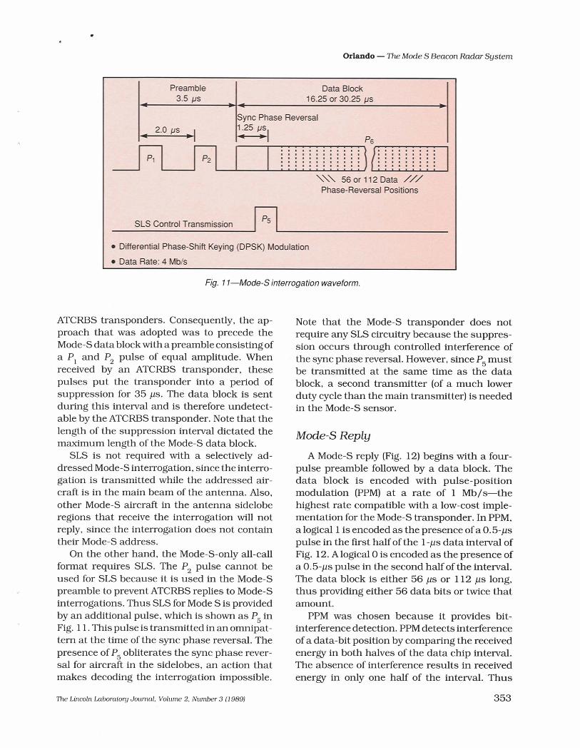
A Mode-S addressed interrogation (Fig. 1 1) begins with a two-pulse preamble followed by a data block. The data block is encoded with differential phase-shift keying (DPSK) at a rate of 4 Mb/s. A logical 1 is encoded as a 180" phase shift and a logical 0 as the absence of a phase shift. DPSK was selected because of its resis- tance to interference [lo]. All data blocks begin with a sync phase reversal that establishes the timing for the remaining phase-reversal posi- tions. The data block is either 16.25 ps or 30.25 ps long, and provides for either 56 bits or 1 12 bits of data, respectively.
The two-pulse preamble is an important ele- ment in the reduction of mutual interference with ATCRBS. It is important that ATCRBS transponders not respond to Mode-S interroga- tions. If they did, such responses would produce ATCRBS replies that would interfere with the reception of Mode-S replies. Moreover, the ATCRBS replies would be synchronized with the Mode-S reply and would therefore lead directly to synchronous garble. Tests with many ATCRBS transponders indicated that there is no practical waveform that is invisible to all
?he Lincoln Laboratory Journal. Volume 2. Number 3 (1 989)
Orlando - The Mode S Beacon Radar System
Fig. I I-Mode-S interrogation waveform.
16.25 or 30.25 ps
Sync Phase Reversal
; ; ; ; ; ; ; ; ; ; ; ;
Pl 1 1 1 1 1 1 1 1 1 1 1 1
p2 1 1 1 1 1 1 1 1 1 1 1 1 1 8 1 1 1 1 1 1 1 1 a 1 1 1 1 1 1 1 1 1 1 1 1 1
\\\ 56 or 1 12 Data /// Phase-Reversal Positions
ATCRBS transponders. Consequently, the ap- proach that was adopted was to precede the Mode-S data block with a preamble consisting of a P, and P2 pulse of equal amplitude. When received by an ATCRBS transponder, these pulses put the transponder into a period of suppression for 35 ps. The data block is sent during this interval and is therefore undetect- able by the ATCRBS transponder. Note that the length of the suppression interval dictated the maximum length of the Mode-S data block.
SLS is not required with a selectively ad- dressed Mode-S interrogation, since the interro- gation is transmitted while the addressed air- craft is in the main beam of the antenna. Also, other Mode-S aircraft in the antenna sidelobe regions that receive the interrogation will not reply, since the interrogation does not contain their Mode-S address.
On the other hand, the Mode-S-only all-call format requires SLS. The P2 pulse cannot be used for SLS because it is used in the Mode-S preamble to prevent ATCRBS replies to Mode-S interrogations. Thus SLS for Mode S is provided by an additional pulse, which is shown as P5 in Fig. 1 1. This pulse is transmitted in an ornnipat- tern at the time of the sync phase reversal. The presence of P, obliterates the sync phase rever- sal for aircraft in the sidelobes, an action that makes decoding the interrogation impossible.
SLS Control Transmission
Note that the Mode-S transponder does not require any SLS circuitry because the suppres- sion occurs through controlled interference of the sync phase reversal. However, since P5 must be transmitted at the same time as the data block, a second transmitter (of a much lower duty cycle than the main transmitter) is needed in the Mode-S sensor.
p5
Mode-S Reply
Differential Phase-Shift Keying (DPSK) Modulation
Data Rate: 4 Mbls
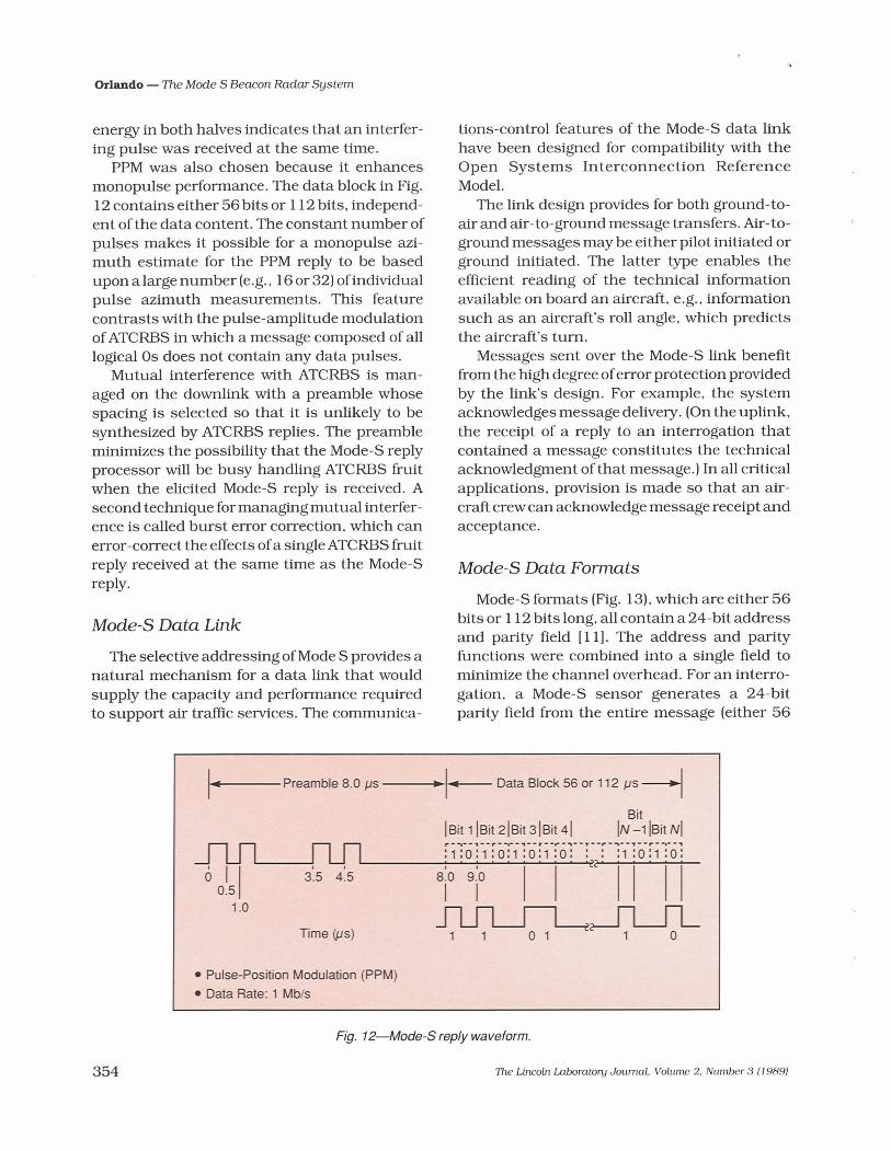
A Mode-S reply (Fig. 12) begins with a four- pulse preamble followed by a data block. The data block is encoded with pulse-position modulation (PPM) at a rate of 1 Mb/s-the highest rate compatible with a low-cost imple- mentation for the Mode-S transponder. In PPM, a logical 1 is encoded as the presence of a 0.5-ys pulse in the first half of the 1-ps data interval of Fig. 12. A logical 0 is encoded as the presence of a 0.5-ps pulse in the second half of the interval. The data block is either 56 ps or 112 ps long, thus providing either 56 data bits or twice that amount.
PPM was chosen because it provides bit- interference detection. PPM detects interference of a data-bit position by comparing the received energy in both halves of the data chip interval. The absence of interference results in received energy in only one half of the interval. Thus
The Lincoln Laboratory Journal, Volume 2, Number 3 (1 989)
Orlando - The Mode S Beacon Radar System
energy in both halves indicates that an interfer- ing pulse was received at the same time.
PPM was also chosen because it enhances monopulse performance. The data block in Fig. 12 contains either 56 bits or 1 12 bits, independ- ent of the data content. The constant number of pulses makes it possible for a monopulse azi- muth estimate for the PPM reply to be based upon a large number (e.g., 16 or 32) of individual pulse azimuth measurements. This feature contrasts with the pulse-amplitude modulation of ATCRBS in which a message composed of all logical 0s does not contain any data pulses.
Mutual interference with ATCRBS is man- aged on the downlink with a preamble whose spacing is selected so that it is unlikely to be synthesized by ATCRBS replies. The preamble minimizes the possibility that the Mode-S reply processor will be busy handling ATCRBS h i t when the elicited Mode-S reply is received. A second technique for managing mutual interfer- ence is called burst error correction, which can error-correct the effects of a single ATCRBS fmit reply received at the same time as the Mode-S reply.
Mode-S Data Link
The selective addressing of Mode S provides a natural mechanism for a data link that would supply the capacity and performance required to support air traffic services. The communica-
tions-control features of the Mode-S data link have been designed for compatibility with the Open Systems Interconnection Reference Model.
The link design provides for both ground-to- air and air- to-ground message transfers. Air- to- ground messages may be either pilot initiated or ground initiated. The latter type enables the efficient reading of the technical information available on board an aircraft, e.g., information such as an aircraft's roll angle, which predicts the aircraft's turn.
Messages sent over the Mode-S link benefit from the high degree of error protection provided by the link's design. For example, the system acknowledges message delivery . (On the uplink, the receipt of a reply to an interrogation that contained a message constitutes the technical acknowledgment of that message.) In all critical applications, provision is made so that an air- craft crew can acknowledge message receipt and acceptance.
Mode-S Data Formats
Mode-S formats (Fig. 13), which are either 56 bits or 1 12 bits long, all contain a 24-bit address and parity field [ll]. The address and parity functions were combined into a single field to minimize the channel overhead. For an interro- gation, a Mode-S sensor generates a 24-bit parity field from the entire message (either 56
I-- preamble 8.0 ps -k- Data Block 56 or 1 12 ps
Bit IBit 1 IBit 21Bit 31Bit 41 IN -1 l ~ i t NI r - - - - , - - r -v- , - - ,"r'-",--p----,--r-v-, : 1 : ~ : 1 : 0 : 1 : 0 : 1 :o: : : :1 :0:1 :o :
6 1 1 3:s 4:s 8:0 9:0 0.5
1 .o I I I I L ' I I I I
Time (ps) 1 1 0 1
Pulse-Position Modulation (PPM) Data Rate: 1 Mbls
- -
Fig. 12-Mode-S reply waveform.
?he Lincoln Laboratory Journal. Volume 2. Number 3 (1 989)


Orlando - The Mode S Beacon Radar System
that are well suited to the needs of air traffic s e ~ c e s . For instance, the association of the Mode-S data link with the surveillance flunction offers a number of operational benefits. Com- munication with an aircraft can be established based solely on surveillance detection. Thus a message can be sent to an otherwise unidenti- fied aircraft. This capability is important for safety services; e.g., warnings can be sent to an unidentified aircraft that is flying too low or that is heading into controlled airspace. Since the same address is used for both surveillance and communication, the possibility of sending a message to the wrong aircraft because of an error in cross-referencing the surveillance and communication identities is eliminated. A fur- ther operational benefit is that communications coverage is assured whenever surveillance coverage exists.
Because of the inherent characteristics of Mode-S sensors, the Mode-S link discourages both accidental and intentional jamming. With a Mode-S radar, coverage is restricted to the sensor's line of sight. This restriction limits not only the airspace in which the sensor can cover traffic, but also the area in which an interfering source can affect the sensor. A narrow antenna beam further limits the active area. Thus a single interfering source, if it is outside the sidelobe region of the sensor, will prevent operation in only a single antenna beamwidth. In the worst case, in which the interfering source is within the sidelobe region (i.e., within a distance of about five miles from the sensor), the source could prevent operation of that sen- sor in all directions. However, the interfering source would have little effect on the opera- tion of all other Mode-S sensors. Thus the distributed nature of Mode S makes it tolerant of interference.
Mode-S Experimental Facility
The Mode-S design was first validated at the Mode-S Experimental Facility (MODSEF), lo- cated at Lincoln Laboratory (Fig. 14). Initially used for link measurements and monopulse development, MODSEF was later upgraded to a fully functional Mode-S sensor. Validation at
MODSEF, however, is not sufficient verification of Mode S because the site does not experience high traffic density, fruit, or ground reflections known as multipath.
Transportable Measurements Facility
The Transportable Measurements Facility (TMF) [12] was constructed for observation of the Mode-S sensor operation at FAA sites known to provide environmental difficulties. TMF (Fig. 15) includes its own antennas, tower, and equipment van that contains a transmitter, receiver, and digitizing and recording equip- ment. The antennas shown in the figure are an Airport Surveillance Radar-7 antenna with a monopulse beacon feed and a monopulse- capable antenna on loan from the United Kingdom. In operation, TMF transmits and then digitizes the received video pulses, which are recorded for subsequent playback and analysis at Lincoln Laboratory.
At most sites, the TMF was operated as close as possible to the existing FAA sensor in order to experience similar environmental con- ditions. Figure 15 shows TMF at Washing- ton's National Airport; the operational ASR is in the background. In two cases, new off-air- port sites were selected to determine their
- d i d
Fig. 1 #-The Mode-S Experimental Facility (MODSEF).
l le Lincoln Laboratory Journal, Volume 2, Number 3 (1 989)

Orlando - The Mode S Beacon Radar System
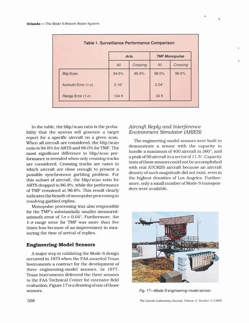
Surveillance Performance Comparison
Fig. 15-The Transportable Measurements Facility (TMF) at Washington's National Airport.
effect on sensor performance. TMF's initial operation and testing took place
at Lincoln Laboratory and Boston's Logan Inter- national Airport. The system was then trans- ported to Philadelphia and Washington to expe- rience the traffic and interference levels of the northeast comdor. Las Vegas, a location well known for its significant ground-bounce multi- path problem, was the next site. Final TMF measurements were made at Los Angeles, which suffers from the highest airport traffic and inter- ference levels in the United States.
Comparison of Automated Radar Terminal System with TMF
At each of the above sites, TMF data was recorded simultaneously with data from the existing FAA sensor. The data enable a direct comparison between the monopulse processing ofTMF and the current Automated Radar Termi- nal System ( A m ) processing.
Figure 16 shows an example of this compari- son for data collected in Philadelphia for an area of 80 nmi by 80 nmi [13]. Figure 16(a) shows ARTS data; Fig. 16(b) shows TMF data. Each point represents an unsmoothed position report measured once each antenna scan. The reduced measurement errors of the TMF data are readily apparent.
Table 1 gives a quantitative comparison of the average performance of ARTS versus TMF for all of the TMF sites. The table confirms the greatly improved qualitative performance seen in Fig. 16.
Fig. 16-Comparison of Automated Radar Terminal Sys- tems (ARTS) versus TMF. (a) A RTS (80 nrni x 80 nmi). (6) TMF monopulse (80 nmi x 80 nmi).
i%e Lincoln Laboratory Journal. Volume 2, Number 3 (1 989)
Orlando - The Mode S Beacon Radar System
In the table, the blip/scan ratio is the proba- bility that the system will generate a target report for a specific aircraft on a given scan. When all aircraft are considered, the blip/scan ratio is 94.6% for ARTS and 98.0% for TMF. The most significant difference in blip/scan per- formance is revealed when only crossing tracks are considered. Crossing tracks are cases in which aircraft are close enough to present a possible synchronous garbling problem. For this subset of aircraft, the blip/scan ratio for ARTS dropped to 86.9%, while the performance of TMF remained at 96.6%. This result clearly indicates the benefit of monopulse processing in resolving garbled replies.
Monopulse processing was also responsible for the TMF's substantially smaller measured- azimuth error of 1 o = 0.04". Furthermore, the 1-0 range error for TMF was more than five times less because of an improvement in mea- suring the time of arrival of replies.
Engineering-Model Sensors
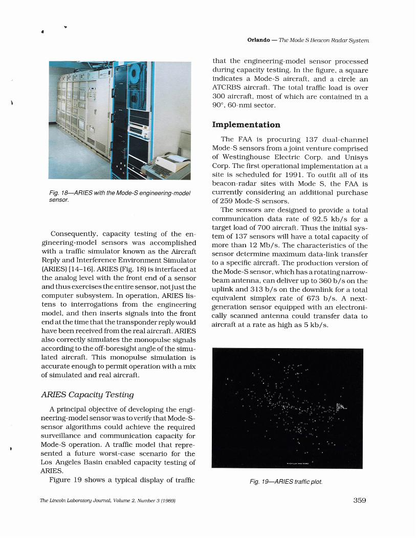
A major step in validating the Mode-S design occurred in 1975 when the FAA awarded Texas Instruments a contract for the development of three engineering-model sensors. In 1977, Texas Instruments delivered the three sensors to the FAA Technical Center for extensive field evaluation. Figure 17 is a drawing of one of those sensors.
Aircraft Reply and Interference Environment Simulator (ARIES]
The engineering-model sensors were built to demonstrate a sensor with the capacity to handle a maximum of 400 aircraft in 360°, and a peak of 50 aircraft in a sector of 1 1.5". Capacity tests of these sensors could not be accomplished with real ATCRBS aircraft because an aircraft density of such magnitude did not exist, even in the highest densities of Los Angeles. Further- more, only a small number of Mode-S transpon- ders were available.
Fig. 1 7-Mode-S engineering-model sensor.
Ihe Lincoln Laboratory Journal. Volume 2, Number 3 (1 989)
Orlando - The Mode S Beacon Radar System
Fig. 18-A RIES with the Mode-S engineering-model sensor.
Consequently, capacity testing of the en- gineering-model sensors was accomplished with a traffic simulator known as the Aircraft Reply and Interference Environment Simulator (ARIES) [ 14- 161. ARIES (Fig. 18) is interfaced at the analog level with the front end of a sensor and thus exercises the entire sensor, not just the computer subsystem. In operation, ARIES lis- tens to interrogations from the engineering model, and then inserts signals into the fi-ont end at the time that the transponder reply would have been received from the real aircraft. ARIES also correctly simulates the monopulse signals according to the off-boresight angle of the simu- lated aircraft. This monopulse simulation is accurate enough to permit operation with a mix of simulated and real aircraft.
ARIES Capacity Testing
A principal objective of developing the engi- neering-model sensor was toverifjr that Mode-S- sensor algorithms could achieve the required surveillance and communication capacity for Mode-S operation. A traffic model that repre- sented a future worst-case scenario for the Los Angeles Basin enabled capacity testing of ARIES.
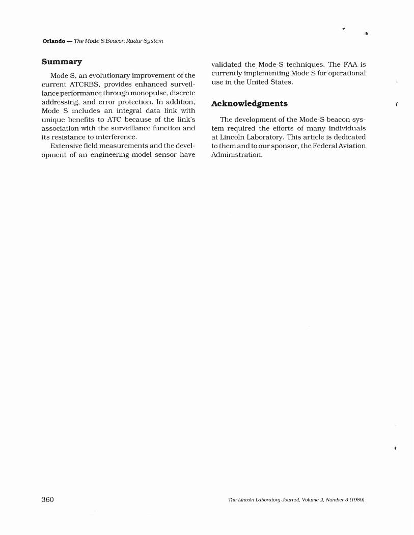
Figure 19 shows a typical display of traffic
that the engineering-model sensor processed during capacity testing. In the figure, a square indicates a Mode-S aircraft, and a circle an ATCRBS aircraft. The total traffic load is over 300 aircraft, most of which are contained in a 90°, 60-nmi sector.
Implementation
The FAA is procuring 137 dual-channel Mode-S sensors from a joint venture comprised of Westinghouse Electric Corp. and Unisys Corp. The first operational implementation at a site is scheduled for 1991. To outfit all of its beacon-radar sites with Mode S, the FAA is currently considering an additional purchase of 259 Mode-S sensors.
The sensors are designed to provide a total communication data rate of 92.5 kb/s for a target load of 700 aircraft. Thus the initial sys- tem of 137 sensors will have a total capacity of more than 12 Mb/s. The characteristics of the sensor determine maximum data-link transfer to a specific aircraft. The production version of the Mode-S sensor, which has a rotating narrow- beam antenna, can deliver up to 360 b/s on the uplink and 313 b/s on the downlink for a total equivalent simplex rate of 673 b/s. A next- generation sensor equipped with an electroni- cally scanned antenna could transfer data to aircraft at a rate as high as 5 kb/s.
Fig. 19-A RIES traffic plot.
?he Lincoln Laboratory Journal, Volume 2, Number 3 (1 9891
Orlando - The Mode S Beacon Radar System
Summary
Mode S, an evolutionary improvement of the current ATCRBS, provides enhanced surveil- lance performance through monopulse, discrete addressing, and error protection. In addition, Mode S includes an integral data link with unique benefits to ATC because of the link's association with the surveillance function and its resistance to interference.
Extensive field measurements and the devel- opment of an engineering-model sensor have
validated the Mode-S techniques. The FAA is currently implementing Mode S for operational use in the United States.
Acknowledgments
The development of the Mode-S beacon sys- tem required the efforts of many individuals at Lincoln Laboratory. This article is dedicated to them and to our sponsor, the Federal Aviation Administration.
The Lincoln Laboratory Journal, Volume 2, Number 3 (1 989)

Orlando - The Mode S Beacon Radar System
References V.A. Orlando and P.R. Drouilhet, "Mode S Beacon System: Functional Description," Project Report ATC-42D, Lincoln Laboratory (29 Aug. 1986). FAA/PM-86/ 1 9. Selection Order: U.S. National Standardfor the IFFMark X (SIF) Air Traffic Control Radar Beacon System (ATCRBS) Characteristics, Dept. of Transportation/ Federal Aviation Administration Order 10 10.5 1A (8 Mar. 1971). D. Karp and M.L. Wood, "DABS Monopulse Summary," Project Report ATC-72, Lincoln Laboratory (4 Feb. 1977). FAA-RD-76-2 19. J.L. Gertz, ''The ATCRBS Mode of DABS," Project Re- port ATC-65, Lincoln Laboratory (31 Jan. 1977). FAA-RD-76-39. E. J. Kelly. "DABS Channel Management," Project Report ATC-43, Lincoln Laboratory (8 Jan. 1975). FAA-RD-74- 197. J.T. Barrows, "DABS Uplink Coding," Project Report ATC-49, Lincoln Laboratory (25 July 1975). FAA-RD-74-62. J.T. Barrows, "DABS Downlink Coding," Project Re- port ATC-48, Lincoln Laboratory (12 Sept. 1975). FAA-RD-75-61. J.D. Welch and P.H. Robeck, "Proposed Technical Characteristics for the Discrete Address Beacon Sys- tem (DABS)," Project Report ATC- 71, Lincoln Laboratory (30 Sept. 1977). FAA-RD-77- 143.
9. Selection Order: U.S. National Aviation Standard for the Mode Select Beacon System (Mode S), Federal Aviation Administration Order 6365.1A (3 Jan. 1983).
10. T.J. Goblick, "DABS Modulation and Coding Design- A Summary." Project Report ATC-52, Lincoln Labora- tory (12 Mar. 1976). FAA-RD-75-93.
11. J.L. Gertz. "Fundamentals of Mode S Parity Coding," Project Report ATC- 1 1 7, Lincoln Laboratory (2 Apr. 1984), DOT/FAA/PM-83/6.
12 R.R. LaFrey, J.E. Laynor, R.G. Nelson, and R.G. Sand- holm. "The Transportable Measurements Facility (TMF) System Description," Project Report Am-91, Lincoln Laboratory (23 May 1980). FAA-RD-79- 1 1 1.
13. W.I. Wells, "Verification of DABS Sensor Surveillance Performance (ATCRBS Mode) at mica1 ASR Sites throughout CONUS," Project Report ATC- 79, Lincoln Laboratory (20 Dec. 1977). FAA-RD-77-113.
14. M. Goon and D.A. Spencer, 'The Aircraft Reply and Interference Environment Simulator (ARIES): Prin- ciples of Operation," Project Report ATC-87 1, Lincoln Laboratory (22 Mar. 1979). FAA-RD-78-96.
15. M. Goon and D.A. Spencer, ''The Aircraft Reply and Interference Environment Simulator (ARIES): Appen- dices to the Principles of Operation," Lincoln Labora- tory Project Report ATC-87 2, Lincoln Laboratory (22 Mar. 1979). FAA-RD-78-96.
16. M. Goon and D.A. Spencer. "The Aircraft Reply and Interference Environment Simulator (ARIES): Pro- grammer's Manual," Project Report A m 8 7 3, Lincoln Laboratory (22 Mar. 1979). FAA-RD-78-96.
The Lincoln Laboratory Journal, Volume 2, Number 3 (1 989)

Orlando - The Mode S Beacon Radar System
VINCENT A. ORLANDO is currently in charge of the System Design and Evalu- ation Group a t Lincoln
-...?: I 7~ search Laboratory, has focused where his on re- air tr&c safety and capacity. Before joining the Laboratory 17 years ago, Vince spent 10 years working on the development of military command and control systems, He received a B.S. in electrical engineering from the University of Cincin- nati, an M.S. in statistics from Stanford University, and a Ph.D. in systems and information science from Syracuse University. A member of Tau Beta Pi and Eta Kappa Nu, Vince was the recipient of a National Science Foundation Traineeship.
'I)ze Lincoln Laborato y Journal, Volume 2, Number 3 (1 989)