Embed Size (px)
Citation preview
The Model Doc Approach to Information Design
Tom Spitzer, VP Engineering
Agenda(are you in the right place?)
• Introduce myself and my company
• Describe our Model Doc approach to defining, maintaining and executing data models
• Go into the details of how Model Doc does Object -> Relational mapping at design time
• Show you a model; run the generator and show some output
• This is NOT a NoSQL session; currently we generate SQL!
• Key Practices: Data management and Integration, Secure Software Development, Self learning Systems, Cyber Security, Process automation
– Trustworthy computing, Cyber Security, PCI, HIPAA, SAS70 etc.
– Large Complex Secure Products /Platforms: concept, design, build, support
– Analytically based platforms: social, financial, marketing, gaming• Disparate data, data warehouse, OLAP, data mining, rules engines
• Predictive modeling, symbolic regression, GP etc.
• Secure systems that become smarter and make the right decision
• International
– Global customers: USA, South America, Europe, China
– 100+ employees: USA, China, Philippines and Peru
• I’ve been at EC Wise 17 of its 18 years in existence, have been developing or managing teams developing data oriented apps for over thirty years
• Effective communications with clients and among our teams is critical
What is Model Doc?• ModelDoc is an XML file that contains definitions of objects
(“entities”) and supporting data types and enumerations.
– i.e. the object model for the system in design
• ModelDocProcessor is a program
– Reads a ModelDoc, and validates
– Generates DDL for creating a data schema, along with HTML documentation of the model.
• Sort of a design time ORM for app developers
– Enables us to think in “objects” but generate the corresponding SQL DB
5
MOTIVATION FOR THIS APPROACH
Inception
• Initially it was about documenting a domain model in a format that we could share and use as a basis for discussion with clients
• There are many ways to do this, and in many projects it is simply not done systematically
• Writing the code generator came later
• Doing so enabled us to establish a consistent set of policies for object to DB mapping
Advantages - General
• Guarantees consistency in the design of the physical database.
• Ensures that every attribute in every class is represented in the physical database, and we know how to find it.
• Switching to a different RDBMS is theoretically simple, providing support is implemented in the ModelDocProcessor engine.
Advantages – Early Development
• Database can change instantly to support new classes, attributes, and relationships described in the object doc.
• Easy to add/change/remove custom data types
• We can experiment with different policies around mapping inheritance, containment, and other OO concepts into a physical database.
• We can switch naming conventions when necessary.– E.g. for a new client
• We can switch policies around primary keys, audit trails, and effective dating at any point.
What it Does Not Do
• Automatically generate a change script to upgrade/downgrade a production database
• However, you can easily generate two different versions of the data model and run a utility to generate a comparison report or script.
So, What’s Wrong with Visual Schema Modeling?
• The ORM challenge
– Developing software requires designing both the business (object) layer and the DB schema
• They may be a little different
– Enterprise Architect addresses this to some extent
– I had this problem two days ago with this model
• Not everybody gets crows feet, especially business clients
• We use EA too, to document, and otherwise
11
MODELDOCSTRUCTURE/METAMODEL
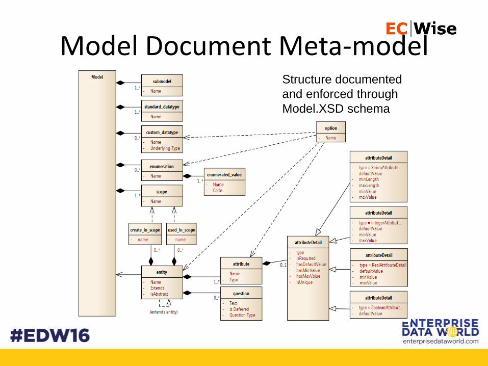
Model Document Meta-modelStructure documented
and enforced through
Model.XSD schema
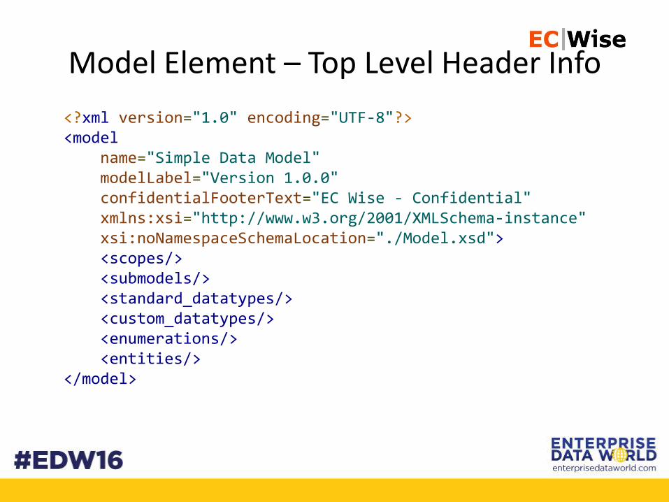
Model Element – Top Level Header Info
<?xml version="1.0" encoding="UTF-8"?><model
name="Simple Data Model"modelLabel="Version 1.0.0"confidentialFooterText="EC Wise - Confidential"xmlns:xsi="http://www.w3.org/2001/XMLSchema-instance"xsi:noNamespaceSchemaLocation="./Model.xsd"><scopes/><submodels/><standard_datatypes/><custom_datatypes/><enumerations/><entities/>
</model>
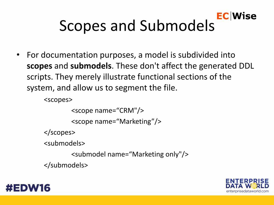
Scopes and Submodels
• For documentation purposes, a model is subdivided into scopes and submodels. These don't affect the generated DDL scripts. They merely illustrate functional sections of the system, and allow us to segment the file.
<scopes>
<scope name=“CRM"/>
<scope name=“Marketing”/>
</scopes>
<submodels>
<submodel name=“Marketing only"/>
</submodels>
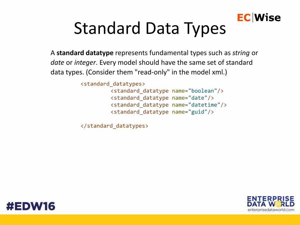
Standard Data TypesA standard datatype represents fundamental types such as string or
date or integer. Every model should have the same set of standard
data types. (Consider them "read-only" in the model xml.)
<standard_datatypes><standard_datatype name="boolean"/><standard_datatype name="date"/><standard_datatype name="datetime"/><standard_datatype name="guid"/>
</standard_datatypes>
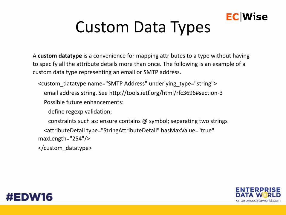
Custom Data Types
A custom datatype is a convenience for mapping attributes to a type without having
to specify all the attribute details more than once. The following is an example of a
custom data type representing an email or SMTP address.
<custom_datatype name="SMTP Address" underlying_type="string">
email address string. See http://tools.ietf.org/html/rfc3696#section-3
Possible future enhancements:
define regexp validation;
constraints such as: ensure contains @ symbol; separating two strings
<attributeDetail type="StringAttributeDetail" hasMaxValue="true"
maxLength="254"/>
</custom_datatype>
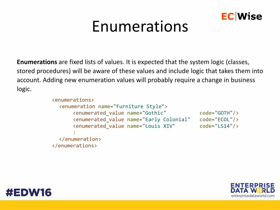
Enumerations
Enumerations are fixed lists of values. It is expected that the system logic (classes,
stored procedures) will be aware of these values and include logic that takes them into
account. Adding new enumeration values will probably require a change in business
logic.
<enumerations><enumeration name="Furniture Style">
<enumerated_value name="Gothic" code="GOTH"/><enumerated_value name="Early Colonial" code="ECOL"/><enumerated_value name="Louis XIV" code="LS14"/>:
</enumeration></enumerations>
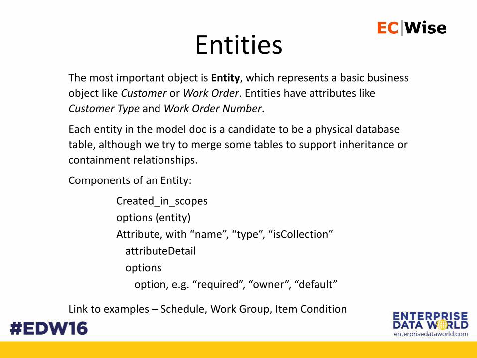
EntitiesThe most important object is Entity, which represents a basic business
object like Customer or Work Order. Entities have attributes like
Customer Type and Work Order Number.
Each entity in the model doc is a candidate to be a physical database
table, although we try to merge some tables to support inheritance or
containment relationships.
Components of an Entity:
Created_in_scopes
options (entity)
Attribute, with “name”, “type”, “isCollection”
attributeDetail
options
option, e.g. “required”, “owner”, “default”
Link to examples – Schedule, Work Group, Item Condition
19
MAPPING POLICIES
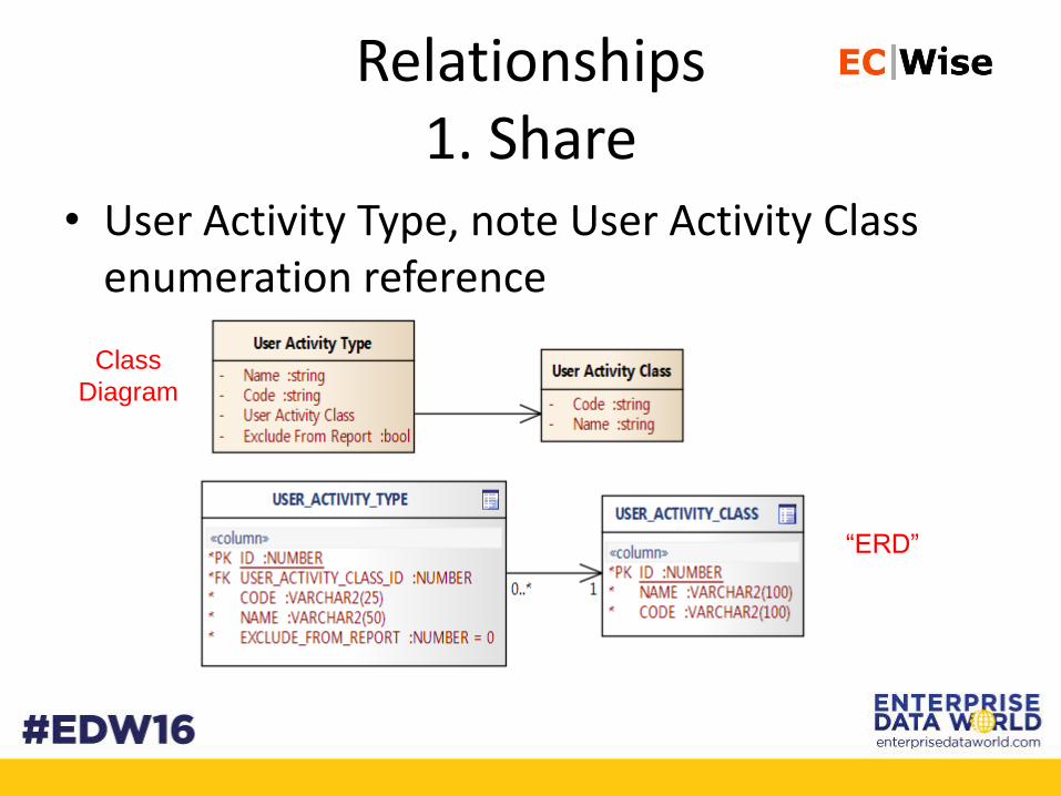
Relationships1. Share
• User Activity Type, note User Activity Class enumeration reference
Class
Diagram
“ERD”
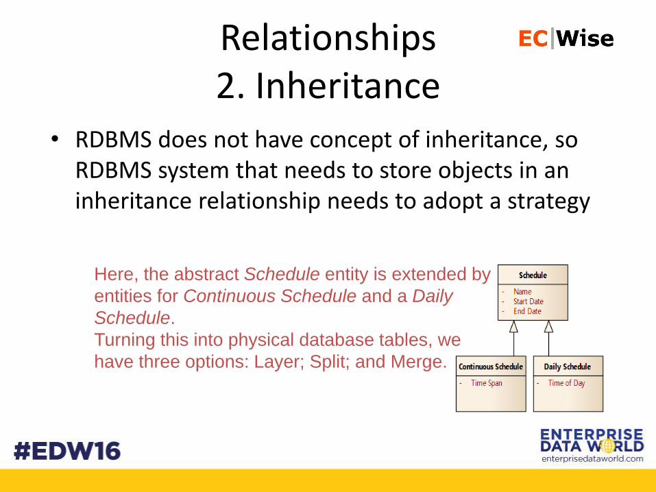
Relationships2. Inheritance
• RDBMS does not have concept of inheritance, so RDBMS system that needs to store objects in an inheritance relationship needs to adopt a strategy
Here, the abstract Schedule entity is extended by
entities for Continuous Schedule and a Daily
Schedule.
Turning this into physical database tables, we
have three options: Layer; Split; and Merge.

Inheritance:Layer Strategy
• When an instance of a Schedule is a Daily Schedule, we get a row in both the Schedule and Daily_Scheduletables.
• To retrieve the full contents of a Schedule, we have to JOIN to the appropriate subclass table. If we don't know the subclass type, then LEFT JOINs should be used to all subclass tables - and some of the columns in the result set will be null:select s.*, c.*, d.*from Schedule sleft join Continuous_Schedule c on
c.ID=s.IDleft join Daily_Schedule d on
d.ID=s.IDwhere s.ID={key}
one table for each class, foreign keys show superclass/subclass relationships
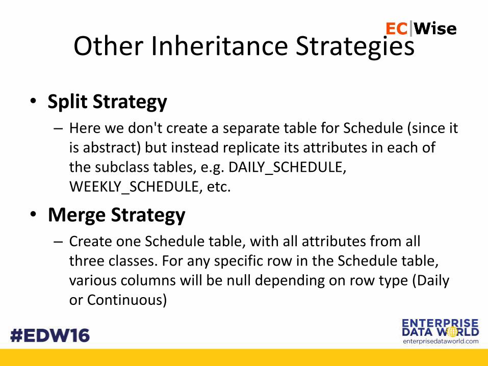
Other Inheritance Strategies
• Split Strategy– Here we don't create a separate table for Schedule (since it
is abstract) but instead replicate its attributes in each of the subclass tables, e.g. DAILY_SCHEDULE, WEEKLY_SCHEDULE, etc.
• Merge Strategy– Create one Schedule table, with all attributes from all
three classes. For any specific row in the Schedule table, various columns will be null depending on row type (Daily or Continuous)
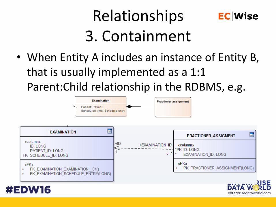
Relationships3. Containment
• When Entity A includes an instance of Entity B, that is usually implemented as a 1:1 Parent:Child relationship in the RDBMS, e.g.
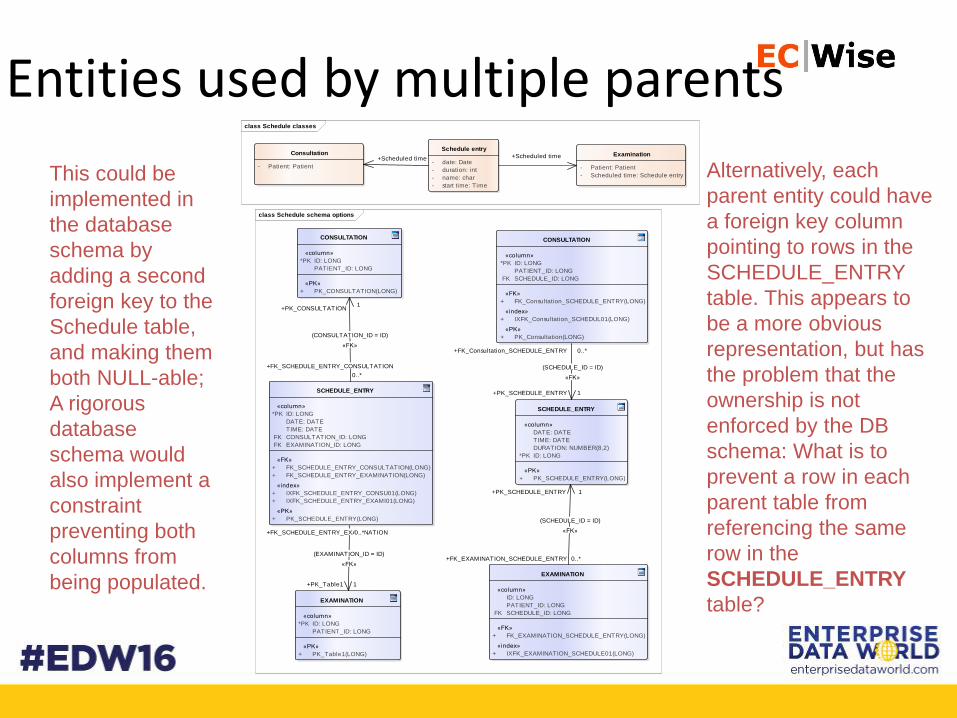
Entities used by multiple parentsclass Schedule classes
Schedule entry
- date: Date
- duration: int
- name: char
- start time: Time
Consultation
- Patient: Patient
Examination
- Patient: Patient
- Scheduled time: Schedule entry
+Scheduled time+Scheduled time
class Schedule schema options
SCHEDULE_ENTRY
«column»
DATE: DATE
TIME: DATE
DURATION: NUMBER(8,2)
*PK ID: LONG
«PK»
+ PK_SCHEDULE_ENTRY(LONG)
EXAMINATION
«column»
ID: LONG
PATIENT_ID: LONG
FK SCHEDULE_ID: LONG
«FK»
+ FK_EXAMINATION_SCHEDULE_ENTRY(LONG)
«index»
+ IXFK_EXAMINATION_SCHEDULE01(LONG)
CONSULTATION
«column»
*PK ID: LONG
PATIENT_ID: LONG
FK SCHEDULE_ID: LONG
«FK»
+ FK_Consultation_SCHEDULE_ENTRY(LONG)
«index»
+ IXFK_Consultation_SCHEDUL01(LONG)
«PK»
+ PK_Consultation(LONG)
CONSULTATION
«column»
*PK ID: LONG
PATIENT_ID: LONG
«PK»
+ PK_CONSULTATION(LONG)
SCHEDULE_ENTRY
«column»
*PK ID: LONG
DATE: DATE
TIME: DATE
FK CONSULTATION_ID: LONG
FK EXAMINATION_ID: LONG
«FK»
+ FK_SCHEDULE_ENTRY_CONSULTATION(LONG)
+ FK_SCHEDULE_ENTRY_EXAMINATION(LONG)
«index»
+ IXFK_SCHEDULE_ENTRY_CONSU01(LONG)
+ IXFK_SCHEDULE_ENTRY_EXAMI01(LONG)
«PK»
+ PK_SCHEDULE_ENTRY(LONG)
EXAMINATION
«column»
*PK ID: LONG
PATIENT_ID: LONG
«PK»
+ PK_Table1(LONG)
+FK_SCHEDULE_ENTRY_CONSULTATION
0..*
(CONSULTATION_ID = ID)
«FK»
+PK_CONSULTATION1
+FK_EXAMINATION_SCHEDULE_ENTRY 0..*
(SCHEDULE_ID = ID)
«FK»
+PK_SCHEDULE_ENTRY 1
+FK_SCHEDULE_ENTRY_EXAMINATION0..*
(EXAMINATION_ID = ID)
«FK»
+PK_Table1 1
+FK_Consultation_SCHEDULE_ENTRY 0..*
(SCHEDULE_ID = ID)
«FK»
+PK_SCHEDULE_ENTRY 1
This could be
implemented in
the database
schema by
adding a second
foreign key to the
Schedule table,
and making them
both NULL-able;
A rigorous
database
schema would
also implement a
constraint
preventing both
columns from
being populated.
Alternatively, each
parent entity could have
a foreign key column
pointing to rows in the
SCHEDULE_ENTRY
table. This appears to
be a more obvious
representation, but has
the problem that the
ownership is not
enforced by the DB
schema: What is to
prevent a row in each
parent table from
referencing the same
row in the
SCHEDULE_ENTRY
table?
26
EXECUTING THE MODEL
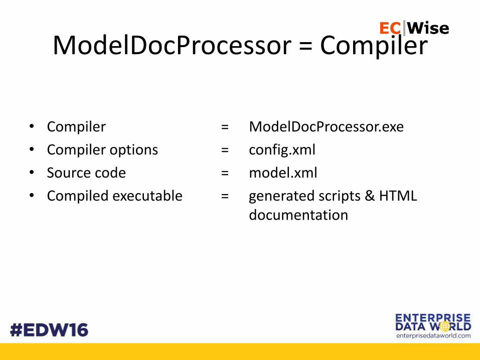
ModelDocProcessor = Compiler
• Compiler =
• Compiler options =
• Source code =
• Compiled executable =
ModelDocProcessor.exe
config.xml
model.xml
generated scripts & HTML documentation
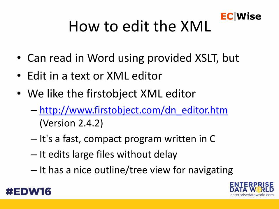
How to edit the XML
• Can read in Word using provided XSLT, but
• Edit in a text or XML editor
• We like the firstobject XML editor
– http://www.firstobject.com/dn_editor.htm(Version 2.4.2)
– It's a fast, compact program written in C
– It edits large files without delay
– It has a nice outline/tree view for navigating
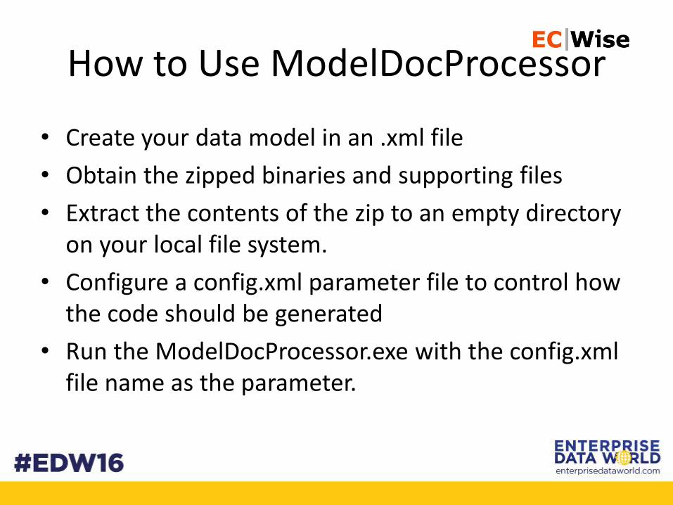
How to Use ModelDocProcessor
• Create your data model in an .xml file
• Obtain the zipped binaries and supporting files
• Extract the contents of the zip to an empty directory on your local file system.
• Configure a config.xml parameter file to control how the code should be generated
• Run the ModelDocProcessor.exe with the config.xml file name as the parameter.
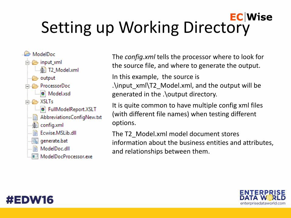
Setting up Working Directory
The config.xml tells the processor where to look for the source file, and where to generate the output.
In this example, the source is .\input_xml\T2_Model.xml, and the output will be generated in the .\output directory.
It is quite common to have multiple config xml files (with different file names) when testing different options.
The T2_Model.xml model document stores information about the business entities and attributes, and relationships between them.
Explore Config Options
Execute the Model
Demo
Comments, Questions, Contact Info
• Does this look useful to anybody?
• Contact info
– Tom SpitzerVP, EngineeringEC Wise, [email protected], @tspitzer_ecwise415-526-5100