Embed Size (px)
Citation preview
TUNGSIX-DRILLDrillLine
The most economical solution for drilling!
Tungaloy Report No. 409-Gw w w . t u n g a l o y . c o m
A C C E L E R A T E D M A C H I N I N G
DrillLine
First double sided 6 cornered insert for drilling with superior performance.
w w w . t u n g a l o y . c o m
4
18
16
14
12
10
8
6
4
2
0 f = 0.08 f = 0.1 f = 0.12 f = 0.15 f = 0.18
One insert type for both the central and peripheral pockets
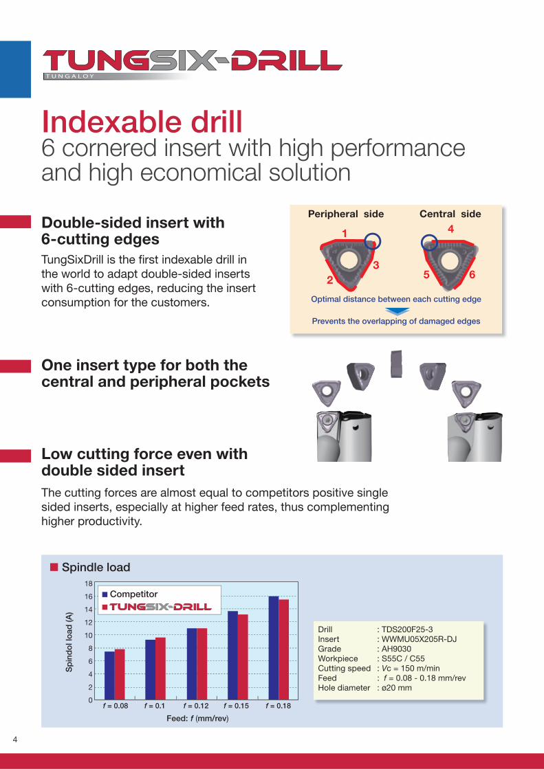
Central sidePeripheral side
Optimal distance between each cutting edge
Prevents the overlapping of damaged edges
Indexable drill6 cornered insert with high performance and high economical solution
Double-sided insert with 6-cutting edges
TungSixDrill is the fi rst indexable drill in
the world to adapt double-sided inserts
with 6-cutting edges, reducing the insert
consumption for the customers.
Low cutting force even with double sided insert
The cutting forces are almost equal to competitors positive single
sided inserts, especially at higher feed rates, thus complementing
higher productivity.
Spindle load
: TDS200F25-3: WWMU05X205R-DJ: AH9030: S55C / C55: Vc = 150 m/min: f = 0.08 - 0.18 mm/rev: ø20 mm
DrillInsertGradeWorkpieceCutting speedFeedHole diameter
Sp
ind
ol lo
ad
(A
)
Feed: f (mm/rev)
Competitor
1 4
5 62
3
5
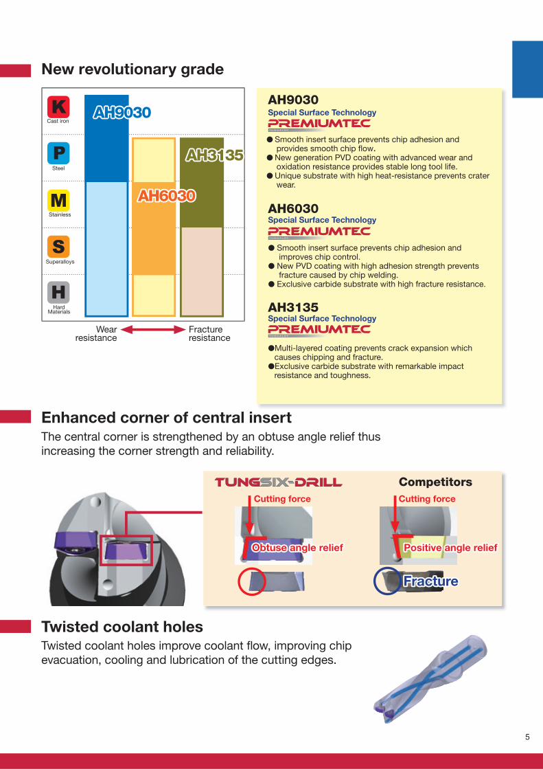
AH6030AH6030
AH9030AH9030
AH3135AH3135
New revolutionary grade
T U N G A LOY
T U N G A LOY
T U N G A LOY
Special Surface Technology
� Smooth insert surface prevents chip adhesion and provides smooth chip fl ow.
� New generation PVD coating with advanced wear and oxidation resistance provides stable long tool life.
� Unique substrate with high heat-resistance prevents crater wear.
Enhanced corner of central insert
Twisted coolant holes
The central corner is strengthened by an obtuse angle relief thus
increasing the corner strength and reliability.
Twisted coolant holes improve coolant fl ow, improving chip
evacuation, cooling and lubrication of the cutting edges.
Obtuse angle reliefObtuse angle relief Positive angle reliefPositive angle relief
FractureFracture
CompetitorsCutting force Cutting force
Special Surface Technology
Special Surface Technology
� Smooth insert surface prevents chip adhesion and improves chip control.
� New PVD coating with high adhesion strength prevents fracture caused by chip welding.
� Exclusive carbide substrate with high fracture resistance.
Wear resistance
Fracture resistance
Cast iron
Steel
Stainless
Superalloys
Hard Materials
�Multi-layered coating prevents crack expansion which causes chipping and fracture.
�Exclusive carbide substrate with remarkable impact resistance and toughness.
AH3135
AH9030
AH6030
6
OK(C)
(P)
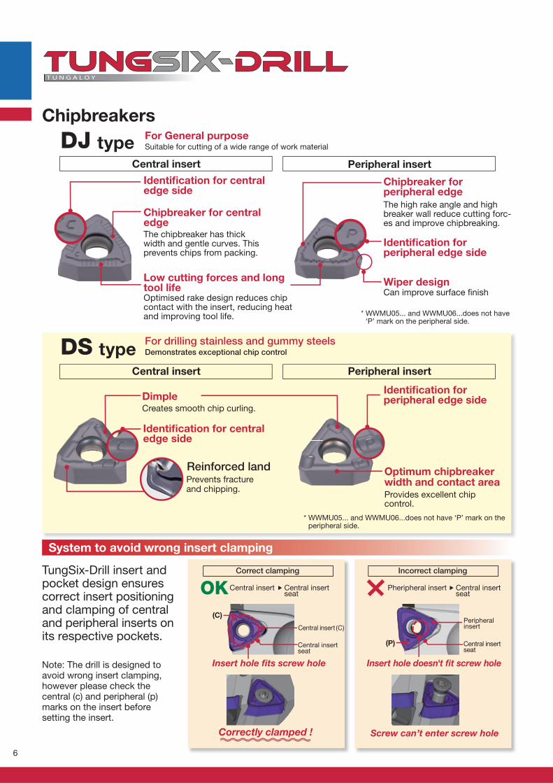
Chipbreakers
TungSix-Drill insert and pocket design ensures correct insert positioning and clamping of central and peripheral inserts on its respective pockets.
System to avoid wrong insert clamping
Note: The drill is designed toavoid wrong insert clamping, however please check the central (c) and peripheral (p) marks on the insert before setting the insert.
Correct clamping Incorrect clamping
Insert hole fi ts screw hole Insert hole doesn't fi t screw hole
Correctly clamped ! Screw can’t enter screw hole
Central insert Pheripheral insertCentral insert seat
Central insert seat
Central insert (C)Peripheral insert
Central insertseat
Central insertseat
Central insert Peripheral insert
DJ type
The chipbreaker has thickwidth and gentle curves. This prevents chips from packing.
The high rake angle and highbreaker wall reduce cutting forc-es and improve chipbreaking.
Optimised rake design reduces chip contact with the insert, reducing heat and improving tool life.
Can improve surface fi nish
* WWMU05... and WWMU06...does not have ‘P’ mark on the peripheral side.
* WWMU05... and WWMU06...does not have ‘P’ mark on the peripheral side.
Chipbreaker for central edge
Identifi cation for central edge side
Chipbreaker for peripheral edge
Identifi cation forperipheral edge side
Low cutting forces and long tool life
Wiper design
Central insert Peripheral insert
Identifi cation for central edge side
Identifi cation forperipheral edge sideDimple
Creates smooth chip curling.
Prevents fracture and chipping.
Reinforced land
Provides excellent chip control.
Optimum chipbreaker width and contact area
For drilling stainless and gummy steelsDemonstrates exceptional chip controlDS type
For General purposeSuitable for cutting of a wide range of work material
7
100 150 200
0.1
0.1
50.2
150 200
20 mm
0.0
80.1
DS
20 mm
DJ
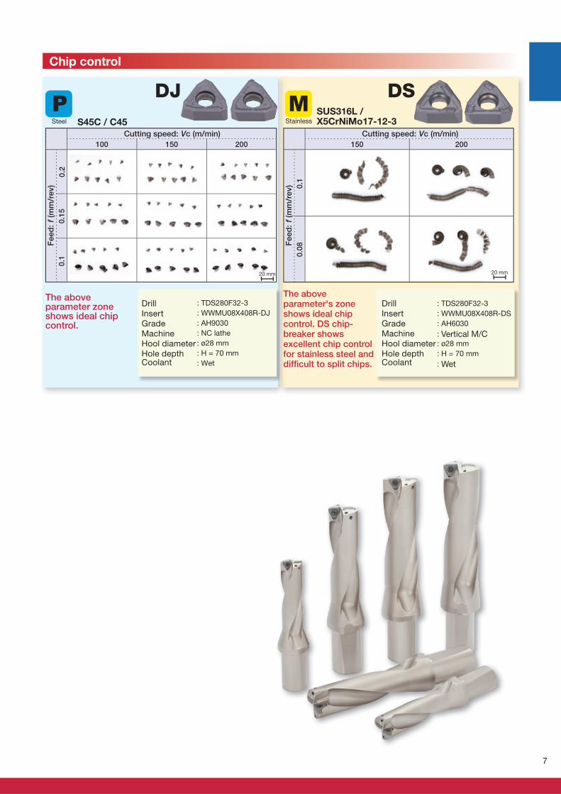
: TDS280F32-3
: WWMU08X408R-DJ
: AH9030
: NC lathe
: ø28 mm
: H = 70 mm
: Wet
Fe
ed
: f (m
m/r
ev)
Cutting speed: Vc (m/min)
The above parameter zone shows ideal chip control.
Chip control
DrillInsertGradeMachineHool diameterHole depthCoolant
: TDS280F32-3
: WWMU08X408R-DS
: AH6030
: Vertical M/C: ø28 mm
: H = 70 mm
: Wet
Fe
ed
: f (m
m/r
ev)
Cutting speed: Vc (m/min)
DrillInsertGradeMachineHool diameterHole depthCoolant
The above parameter's zone shows ideal chip control. DS chip-breaker shows excellent chip control for stainless steel and diffi cult to split chips.
SUS316L / X5CrNiMo17-12-3S45C / C45Steel Stainless
8
0.4
0.3
0.2
0.1
05 10 15 20
0.35
0.3
0.25
0.2
0.15
0.1
0.05
0 0.5 1
Vc (m/min)
DS AH6030 160 - 250
DJ AH9030 160 - 320
DJ AH9030 80 - 250
DJ AH3135 80 - 250
DS AH6030 160 - 250
DJ AH9030 160 - 250
DJ AH9030 80 - 200
DJ AH3135 80 - 200
DS AH6030 100 - 200
DJ AH3135 100 - 200
DS AH6030 100 - 200
DJ AH3135 100 - 200
DS AH6030 80 - 120
DJ AH3135 80 - 120
DJ AH9030 80 - 250
DJ AH3135 80 - 200
DJ AH9030 80 - 200
DJ AH3135 80 - 150
DS AH6030 200 - 400
- DJ AH9030 200 - 400
DS AH6030 20 - 60
DJ AH3135 20 - 60
DS AH6030 40 - 120
DJ AH3135 40 - 120
DJ AH9030 50 - 100
DJ AH3135 40 - 80
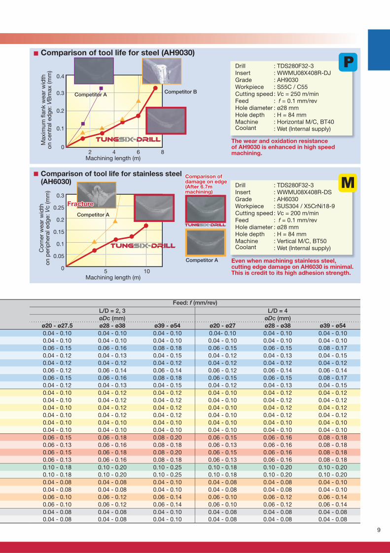
Excellent wear resistance of AH9030
Thougness of central insert
AH9030 offers superior wear resistance against competitors.
Enhanced corner of central cuttingedge prevents fracture even in pre-hardened steel machining.
Competitor A
Competitor A
Competitor B
Co
rner
wear
wid
th
on
perip
hera
l ed
ge: V
c (m
m)
Maxim
um
fl a
nk w
ear
wid
th
on c
entr
al ed
ge: V
Bm
ax (m
m)
Tool life
: TDS280F32-3: WWMU08X408R-DJ: AH9030: S55C / C55: Vc = 140 m/min: f = 0.1 mm/rev: ø28 mm: H = 84 mm: Horizontal M/C, BT40: Wet (Internal supply)
: TDS280F32-3: WWMU08X408R-DJ: AH9030: Pre-hardened steel (40HRC): Vc = 100 m/min: f = 0.08 mm/rev: ø28 mm: H = 28 mm: Vertical M/C, BT50: Wet (Internal supply)
Fracture
DrillInsertGradeWorkpieceCutting speedFeedHole diameterHole depthMachineCoolant
DrillInsertGradeWorkpieceCutting speedFeedHole diameterHole depthMachineCoolant
Machining length (m)
Machining length (m)
Standard cutting conditions
Workpiece materialsCutting speed
Low carbon steels (C < 0.3) SS400, SM490, S25C etc. (St42-1, St52-3, C25 etc.)
Carbon steels (C > 0.3)S45C, S55C etc. (C45, C55 etc.)
Low alloy steelsSCM415 etc.
Alloy steelsSCM440, SCr420 etc. (42CrMo4, 20Cr4 etc.)
Stainless steels (Austenitic)SUS304, SUS316 etc. (X5CrNi18-9, X5CrNiMo17-12-2 etc.)
Stainless steels (Martensitic and ferritic)SUS430, SUS416 etc. (X6Cr17, X20Cr13 etc.)
Stainless steels (Precipitation hardening)SUS630 etc. (X5CrNiCuNb16-4 etc.)
Grey cast ironsFC250 etc. (GG25 etc.)
Ductile cast ironsFCD700 etc. (GGG70 etc.)
GradeISOChip-
breakerSelection criteria
Aluminium alloy
High temperature alloyInconel718 etc
Titanium AlooyTi-6Al-4V etc.
Hardened steelOver 40HRC
First choice
Priority on wear resistance
First choice
Priority on impact resistance
First choice
Priority on wear resistance
First choice
Priority on impact resistance
First choice
Priority on impact resistance
First choice
Priority on impact resistance
First choice
Priority on impact resistance
First choice
Priority on impact resistance
First choice
Priority on impact resistance
First choice
First choice
Priority on impact resistance
First choice
Priority on impact resistance
First choice
Priority on impact resistance
9
0.4
0.3
0.2
0.1
02 4 6 8
0.3
0.25
0.2
0.15
0.1
0.05
05 10
L/D = 2, 3 L/D = 4
øDc (mm) øDc (mm)
ø20 - ø27.5 ø28 - ø38 ø39 - ø54 ø20 - ø27 ø28 - ø38 ø39 - ø54
0.04 - 0.10 0.04 - 0.10 0.04 - 0.10 0.04- 0.10 0.04 - 0.10 0.04 - 0.10
0.04 - 0.10 0.04 - 0.10 0.04 - 0.10 0.04 - 0.10 0.04 - 0.10 0.04 - 0.10
0.06 - 0.15 0.06 - 0.16 0.08 - 0.18 0.06 - 0.15 0.06 - 0.15 0.08 - 0.17
0.04 - 0.12 0.04 - 0.13 0.04 - 0.15 0.04 - 0.12 0.04 - 0.13 0.04 - 0.15
0.04 - 0.12 0.04 - 0.12 0.04 - 0.12 0.04 - 0.12 0.04 - 0.12 0.04 - 0.12
0.06 - 0.12 0.06 - 0.14 0.06 - 0.14 0.06 - 0.12 0.06 - 0.14 0.06 - 0.14
0.06 - 0.15 0.06 - 0.16 0.08 - 0.18 0.06 - 0.15 0.06 - 0.15 0.08 - 0.17
0.04 - 0.12 0.04 - 0.13 0.04 - 0.15 0.04 - 0.12 0.04 - 0.13 0.04 - 0.15
0.04 - 0.10 0.04 - 0.12 0.04 - 0.12 0.04 - 0.10 0.04 - 0.12 0.04 - 0.12
0.04 - 0.10 0.04 - 0.12 0.04 - 0.12 0.04 - 0.10 0.04 - 0.12 0.04 - 0.12
0.04 - 0.10 0.04 - 0.12 0.04 - 0.12 0.04 - 0.10 0.04 - 0.12 0.04 - 0.12
0.04 - 0.10 0.04 - 0.12 0.04 - 0.12 0.04 - 0.10 0.04 - 0.12 0.04 - 0.12
0.04 - 0.10 0.04 - 0.10 0.04 - 0.10 0.04 - 0.10 0.04 - 0.10 0.04 - 0.10
0.04 - 0.10 0.04 - 0.10 0.04 - 0.10 0.04 - 0.10 0.04 - 0.10 0.04 - 0.10
0.06 - 0.15 0.06 - 0.18 0.08 - 0.20 0.06 - 0.15 0.06 - 0.16 0.08 - 0.18
0.06 - 0.13 0.06 - 0.16 0.08 - 0.18 0.06 - 0.13 0.06 - 0.16 0.08 - 0.18
0.06 - 0.15 0.06 - 0.18 0.08 - 0.20 0.06 - 0.15 0.06 - 0.16 0.08 - 0.18
0.06 - 0.13 0.06 - 0.16 0.08 - 0.18 0.06 - 0.13 0.06 - 0.16 0.08 - 0.18
0.10 - 0.18 0.10 - 0.20 0.10 - 0.25 0.10 - 0.18 0.10 - 0.20 0.10 - 0.20
0.10 - 0.18 0.10 - 0.20 0.10 - 0.25 0.10 - 0.18 0.10 - 0.20 0.10 - 0.20
0.04 - 0.08 0.04 - 0.08 0.04 - 0.10 0.04 - 0.08 0.04 - 0.08 0.04 - 0.10
0.04 - 0.08 0.04 - 0.08 0.04 - 0.10 0.04 - 0.08 0.04 - 0.08 0.04 - 0.10
0.06 - 0.10 0.06 - 0.12 0.06 - 0.14 0.06 - 0.10 0.06 - 0.12 0.06 - 0.14
0.06 - 0.10 0.06 - 0.12 0.06 - 0.14 0.06 - 0.10 0.06 - 0.12 0.06 - 0.14
0.04 - 0.08 0.04 - 0.08 0.04 - 0.10 0.04 - 0.08 0.04 - 0.08 0.04 - 0.08
0.04 - 0.08 0.04 - 0.08 0.04 - 0.10 0.04 - 0.08 0.04 - 0.08 0.04 - 0.08
Competitor ACompetitor B
The wear and oxidation resistance of AH9030 is enhanced in high speed machining.
Machining length (m)
Maxim
um
fl a
nk w
ear
wid
th
on
cen
tral ed
ge: V
Bm
ax (m
m)
Comparison of tool life for steel (AH9030)
DrillInsertGradeWorkpieceCutting speedFeedHole diameterHole depthMachineCoolant
: TDS280F32-3: WWMU08X408R-DJ: AH9030: S55C / C55: Vc = 250 m/min: f = 0.1 mm/rev: ø28 mm: H = 84 mm: Horizontal M/C, BT40: Wet (Internal supply)
Competitor A
Even when machining stainless steel, cutting edge damage on AH6030 is minimal. This is credit to its high adhesion strength.
Machining length (m)
Co
rner
wear
wid
th
on p
erip
hera
l ed
ge: V
c (m
m)
Comparison of tool life for stainless steel (AH6030)
DrillInsertGradeWorkpieceCutting speedFeedHole diameterHole depthMachineCoolant
: TDS280F32-3: WWMU08X408R-DS: AH6030: SUS304 / X5CrNi18-9: Vc = 200 m/min: f = 0.1 mm/rev: ø28 mm: H = 84 mm: Vertical M/C, BT50: Wet (Internal supply)
FractureFracture
Comparison of Comparison of damage on edgedamage on edge(After 6.7m (After 6.7m machining)machining)
Competitor A
Feed: f (mm/rev)
10
øDc øDs øD r Ltm Lf rs L
TDS200F25-2 ● 20.0 25 32 40 44 61.0 54 115.0 1.0 0.3 WWMU05X205R-D* CSPB-2.2 IP-7D
TDS205F25-2 ● 20.5 25 32 41 45 62.5 54 116.5 0.9 0.3 WWMU05X205R-D* CSPB-2.2 IP-7D
TDS210F25-2 ● 21.0 25 32 42 46 64.0 54 118.0 0.8 0.3 WWMU05X205R-D* CSPB-2.2 IP-7D
TDS215F25-2 ● 21.5 25 32 43 47 65.0 54 119.0 0.6 0.3 WWMU05X205R-D* CSPB-2.2 IP-7D
TDS220F25-2 ● 22.0 25 32 44 48 66.0 54 120.0 0.5 0.3 WWMU05X205R-D* CSPB-2.2 IP-7D
TDS225F25-2 ● 22.5 25 37 45 49 67.5 54 121.5 0.4 0.3 WWMU05X205R-D* CSPB-2.2 IP-7D
TDS230F25-2 ● 23.0 25 37 46 50 69.0 54 123.0 0.3 0.4 WWMU05X205R-D* CSPB-2.2 IP-7D
TDS235F25-2 ● 23.5 25 37 47 51 70.0 54 124.0 0.2 0.4 WWMU05X205R-D* CSPB-2.2 IP-7D
TDS240F25-2 ● 24.0 25 37 48 52 71.0 54 125.0 1.2 0.4 WWMU060306R-D* CSPB-2.5 IP-8D
TDS245F25-2 ● 24.5 25 37 49 53 72.5 54 126.5 1.0 0.4 WWMU060306R-D* CSPB-2.5 IP-8D
TDS250F25-2 ● 25.0 25 37 50 54 74.0 54 128.0 0.8 0.4 WWMU060306R-D* CSPB-2.5 IP-8D
TDS255F25-2 ● 25.5 25 37 51 55 75.5 54 129.5 0.6 0.4 WWMU060306R-D* CSPB-2.5 IP-8D
TDS260F25-2 ● 26.0 25 37 52 56 77.0 54 131.0 0.5 0.4 WWMU060306R-D* CSPB-2.5 IP-8D
TDS270F32-2 ● 27.0 32 40 54 58 79.0 59 138.0 0.3 0.6 WWMU060306R-D* CSPB-2.5 IP-8D
TDS280F32-2 ● 28.0 32 40 56 60 82.0 59 141.0 1.3 0.6 WWMU08X408R-D* CSTB-3 T-9D
TDS290F32-2 ● 29.0 32 40 58 62 84.0 59 143.0 1.1 0.7 WWMU08X408R-D* CSTB-3 T-9D
TDS300F32-2 ● 30.0 32 40 60 64 87.0 59 146.0 0.8 0.7 WWMU08X408R-D* CSTB-3 T-9D
TDS310F32-2 ● 31.0 32 40 62 66 90.0 59 149.0 0.5 0.7 WWMU08X408R-D* CSTB-3 T-9D
TDS320F32-2 ● 32.0 32 40 64 68 92.0 59 151.0 0.2 0.8 WWMU08X408R-D* CSTB-3 T-9D
TDS330F40-2 ● 33.0 40 50 66 70 95.0 69 164.0 1.7 1.2 WWMU09X510R-D* CSTB-4 T-15D
TDS340F40-2 ● 34.0 40 50 68 72 98.0 69 167.0 1.4 1.2 WWMU09X510R-D* CSTB-4 T-15D
TDS350F40-2 ● 35.0 40 50 70 74 101.0 69 170.0 1.2 1.2 WWMU09X510R-D* CSTB-4 T-15D
TDS360F40-2 ● 36.0 40 50 72 76 104.0 69 173.0 0.9 1.3 WWMU09X510R-D* CSTB-4 T-15D
TDS370F40-2 ● 37.0 40 50 74 78 105.0 69 174.0 0.7 1.3 WWMU09X510R-D* CSTB-4 T-15D
TDS380F40-2 ● 38.0 40 50 76 80 108.0 69 177.0 0.4 1.3 WWMU09X510R-D* CSTB-4 T-15D
TDS390F40-2 ● 39.0 40 50 78 82 110.0 69 179.0 2.2 1.4 WWMU11X512R-D* CSTB-5 T-20D
TDS400F40-2 ● 40.0 40 50 80 84 113.0 69 182.0 1.9 1.4 WWMU11X512R-D* CSTB-5 T-20D
TDS410F40-2 ● 41.0 40 50 82 86 117.0 69 186.0 1.7 1.5 WWMU11X512R-D* CSTB-5 T-20D
TDS420F40-2 ● 42.0 40 55 84 88 119.0 69 188.0 1.5 1.6 WWMU11X512R-D* CSTB-5 T-20D
TDS430F40-2 ● 43.0 40 55 86 90 122.0 69 191.0 1.3 1.6 WWMU11X512R-D* CSTB-5 T-20D
TDS440F40-2 ● 44.0 40 55 88 92 124.0 69 193.0 1.0 1.7 WWMU11X512R-D* CSTB-5 T-20D
TDS450F40-2 ● 45.0 40 55 90 94 127.0 69 196.0 0.7 1.7 WWMU11X512R-D* CSTB-5 T-20D
TDS460F40-2 ● 46.0 40 55 92 96 130.0 69 199.0 0.4 1.8 WWMU11X512R-D* CSTB-5 T-20D
TDS470F40-2 ● 47.0 40 55 94 98 132.0 69 201.0 2.6 1.9 WWMU13X512R-D* CSTB-5 T-20D
TDS480F40-2 ● 48.0 40 55 96 100 135.0 69 204.0 2.4 1.9 WWMU13X512R-D* CSTB-5 T-20D
TDS490F40-2 ● 49.0 40 55 98 102 137.0 69 206.0 2.2 1.9 WWMU13X512R-D* CSTB-5 T-20D
TDS500F40-2 ● 50.0 40 55 100 104 140.0 69 209.0 2.0 2.0 WWMU13X512R-D* CSTB-5 T-20D
TDS510F40-2 ● 51.0 40 55 102 106 144.0 69 213.0 1.7 2.1 WWMU13X512R-D* CSTB-5 T-20D
TDS520F40-2 ● 52.0 40 55 104 108 146.0 69 215.0 1.5 2.2 WWMU13X512R-D* CSTB-5 T-20D
TDS530F40-2 ● 53.0 40 55 106 110 149.0 69 218.0 1.3 2.3 WWMU13X512R-D* CSTB-5 T-20D
TDS540F40-2 ● 54.0 40 55 108 112 151.0 69 220.0 1.0 2.4 WWMU13X512R-D* CSTB-5 T-20D
L
R
Rs
øDc
øDsh
6
øD
LfLtm
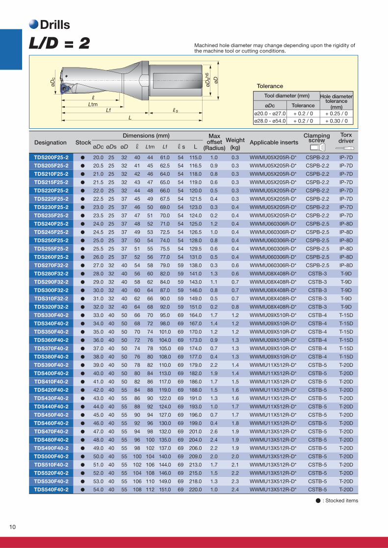
(mm)øDc
ø20.0 - ø27.0 + 0.2 / 0 + 0.25 / 0
ø28.0 - ø54.0 + 0.2 / 0 + 0.30 / 0
L/D = 2Drills
Dimensions (mm)Applicable inserts
Maxoffset
(Radius)
Weight
(kg)
Clamping screw
Torx driver Designation Stock
Tool diameter (mm)
Tolerance
Hole diametertolerance
Tolerance
Machined hole diameter may change depending upon the rigidity of the machine tool or cutting conditions.
� : Stocked items
11
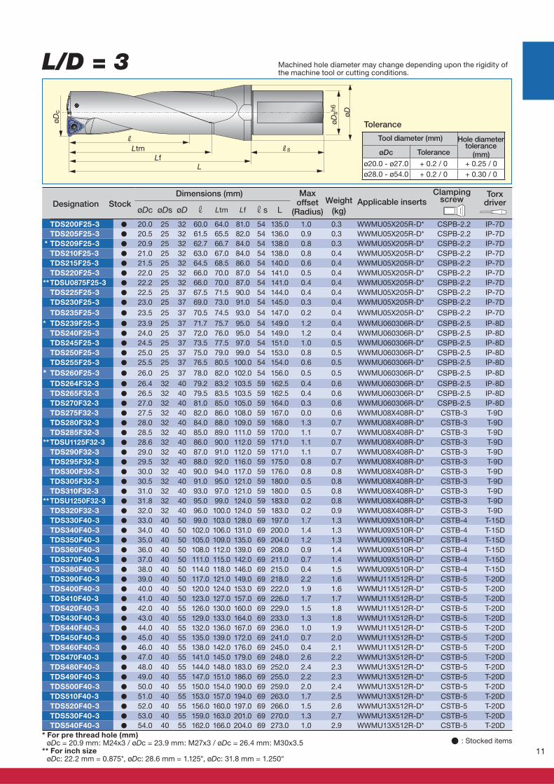
L/D = 3
øDc øDs øD r Ltm Lf rs L
TDS200F25-3 ● 20.0 25 32 60.0 64.0 81.0 54 135.0 1.0 0.3 WWMU05X205R-D* CSPB-2.2 IP-7D
TDS205F25-3 ● 20.5 25 32 61.5 65.5 82.0 54 136.0 0.9 0.3 WWMU05X205R-D* CSPB-2.2 IP-7D
* TDS209F25-3 ● 20.9 25 32 62.7 66.7 84.0 54 138.0 0.8 0.3 WWMU05X205R-D* CSPB-2.2 IP-7D
TDS210F25-3 ● 21.0 25 32 63.0 67.0 84.0 54 138.0 0.8 0.4 WWMU05X205R-D* CSPB-2.2 IP-7D
TDS215F25-3 ● 21.5 25 32 64.5 68.5 86.0 54 140.0 0.6 0.4 WWMU05X205R-D* CSPB-2.2 IP-7D
TDS220F25-3 ● 22.0 25 32 66.0 70.0 87.0 54 141.0 0.5 0.4 WWMU05X205R-D* CSPB-2.2 IP-7D
**TDSU0875F25-3 ● 22.2 25 32 66.0 70.0 87.0 54 141.0 0.4 0.4 WWMU05X205R-D* CSPB-2.2 IP-7D
TDS225F25-3 ● 22.5 25 37 67.5 71.5 90.0 54 144.0 0.4 0.4 WWMU05X205R-D* CSPB-2.2 IP-7D
TDS230F25-3 ● 23.0 25 37 69.0 73.0 91.0 54 145.0 0.3 0.4 WWMU05X205R-D* CSPB-2.2 IP-7D
TDS235F25-3 ● 23.5 25 37 70.5 74.5 93.0 54 147.0 0.2 0.4 WWMU05X205R-D* CSPB-2.2 IP-7D
* TDS239F25-3 ● 23.9 25 37 71.7 75.7 95.0 54 149.0 1.2 0.4 WWMU060306R-D* CSPB-2.5 IP-8D
TDS240F25-3 ● 24.0 25 37 72.0 76.0 95.0 54 149.0 1.2 0.4 WWMU060306R-D* CSPB-2.5 IP-8D
TDS245F25-3 ● 24.5 25 37 73.5 77.5 97.0 54 151.0 1.0 0.5 WWMU060306R-D* CSPB-2.5 IP-8D
TDS250F25-3 ● 25.0 25 37 75.0 79.0 99.0 54 153.0 0.8 0.5 WWMU060306R-D* CSPB-2.5 IP-8D
TDS255F25-3 ● 25.5 25 37 76.5 80.5 100.0 54 154.0 0.6 0.5 WWMU060306R-D* CSPB-2.5 IP-8D
* TDS260F25-3 ● 26.0 25 37 78.0 82.0 102.0 54 156.0 0.5 0.5 WWMU060306R-D* CSPB-2.5 IP-8D
TDS264F32-3 ● 26.4 32 40 79.2 83.2 103.5 59 162.5 0.4 0.6 WWMU060306R-D* CSPB-2.5 IP-8D
TDS265F32-3 ● 26.5 32 40 79.5 83.5 103.5 59 162.5 0.4 0.6 WWMU060306R-D* CSPB-2.5 IP-8D
TDS270F32-3 ● 27.0 32 40 81.0 85.0 105.0 59 164.0 0.3 0.6 WWMU060306R-D* CSPB-2.5 IP-8D
TDS275F32-3 ● 27.5 32 40 82.0 86.0 108.0 59 167.0 0.0 0.6 WWMU08X408R-D* CSTB-3 T-9D
TDS280F32-3 ● 28.0 32 40 84.0 88.0 109.0 59 168.0 1.3 0.7 WWMU08X408R-D* CSTB-3 T-9D
TDS285F32-3 ● 28.5 32 40 85.0 89.0 111.0 59 170.0 1.1 0.7 WWMU08X408R-D* CSTB-3 T-9D
**TDSU1125F32-3 ● 28.6 32 40 86.0 90.0 112.0 59 171.0 1.1 0.7 WWMU08X408R-D* CSTB-3 T-9D
TDS290F32-3 ● 29.0 32 40 87.0 91.0 112.0 59 171.0 1.1 0.7 WWMU08X408R-D* CSTB-3 T-9D
TDS295F32-3 ● 29.5 32 40 88.0 92.0 116.0 59 175.0 0.8 0.7 WWMU08X408R-D* CSTB-3 T-9D
TDS300F32-3 ● 30.0 32 40 90.0 94.0 117.0 59 176.0 0.8 0.8 WWMU08X408R-D* CSTB-3 T-9D
TDS305F32-3 ● 30.5 32 40 91.0 95.0 121.0 59 180.0 0.5 0.8 WWMU08X408R-D* CSTB-3 T-9D
TDS310F32-3 ● 31.0 32 40 93.0 97.0 121.0 59 180.0 0.5 0.8 WWMU08X408R-D* CSTB-3 T-9D
**TDSU1250F32-3 ● 31.8 32 40 95.0 99.0 124.0 59 183.0 0.2 0.8 WWMU08X408R-D* CSTB-3 T-9D
TDS320F32-3 ● 32.0 32 40 96.0 100.0 124.0 59 183.0 0.2 0.9 WWMU08X408R-D* CSTB-3 T-9D
TDS330F40-3 ● 33.0 40 50 99.0 103.0 128.0 69 197.0 1.7 1.3 WWMU09X510R-D* CSTB-4 T-15D
TDS340F40-3 ● 34.0 40 50 102.0 106.0 131.0 69 200.0 1.4 1.3 WWMU09X510R-D* CSTB-4 T-15D
TDS350F40-3 ● 35.0 40 50 105.0 109.0 135.0 69 204.0 1.2 1.3 WWMU09X510R-D* CSTB-4 T-15D
TDS360F40-3 ● 36.0 40 50 108.0 112.0 139.0 69 208.0 0.9 1.4 WWMU09X510R-D* CSTB-4 T-15D
TDS370F40-3 ● 37.0 40 50 111.0 115.0 142.0 69 211.0 0.7 1.4 WWMU09X510R-D* CSTB-4 T-15D
TDS380F40-3 ● 38.0 40 50 114.0 118.0 146.0 69 215.0 0.4 1.5 WWMU09X510R-D* CSTB-4 T-15D
TDS390F40-3 ● 39.0 40 50 117.0 121.0 149.0 69 218.0 2.2 1.6 WWMU11X512R-D* CSTB-5 T-20D
TDS400F40-3 ● 40.0 40 50 120.0 124.0 153.0 69 222.0 1.9 1.6 WWMU11X512R-D* CSTB-5 T-20D
TDS410F40-3 ● 41.0 40 50 123.0 127.0 157.0 69 226.0 1.7 1.7 WWMU11X512R-D* CSTB-5 T-20D
TDS420F40-3 ● 42.0 40 55 126.0 130.0 160.0 69 229.0 1.5 1.8 WWMU11X512R-D* CSTB-5 T-20D
TDS430F40-3 ● 43.0 40 55 129.0 133.0 164.0 69 233.0 1.3 1.8 WWMU11X512R-D* CSTB-5 T-20D
TDS440F40-3 ● 44.0 40 55 132.0 136.0 167.0 69 236.0 1.0 1.9 WWMU11X512R-D* CSTB-5 T-20D
TDS450F40-3 ● 45.0 40 55 135.0 139.0 172.0 69 241.0 0.7 2.0 WWMU11X512R-D* CSTB-5 T-20D
TDS460F40-3 ● 46.0 40 55 138.0 142.0 176.0 69 245.0 0.4 2.1 WWMU11X512R-D* CSTB-5 T-20D
TDS470F40-3 ● 47.0 40 55 141.0 145.0 179.0 69 248.0 2.6 2.2 WWMU13X512R-D* CSTB-5 T-20D
TDS480F40-3 ● 48.0 40 55 144.0 148.0 183.0 69 252.0 2.4 2.3 WWMU13X512R-D* CSTB-5 T-20D
TDS490F40-3 ● 49.0 40 55 147.0 151.0 186.0 69 255.0 2.2 2.3 WWMU13X512R-D* CSTB-5 T-20D
TDS500F40-3 ● 50.0 40 55 150.0 154.0 190.0 69 259.0 2.0 2.4 WWMU13X512R-D* CSTB-5 T-20D
TDS510F40-3 ● 51.0 40 55 153.0 157.0 194.0 69 263.0 1.7 2.5 WWMU13X512R-D* CSTB-5 T-20D
TDS520F40-3 ● 52.0 40 55 156.0 160.0 197.0 69 266.0 1.5 2.6 WWMU13X512R-D* CSTB-5 T-20D
TDS530F40-3 ● 53.0 40 55 159.0 163.0 201.0 69 270.0 1.3 2.7 WWMU13X512R-D* CSTB-5 T-20D
TDS540F40-3 ● 54.0 40 55 162.0 166.0 204.0 69 273.0 1.0 2.9 WWMU13X512R-D* CSTB-5 T-20D
L
RRs
øDc
øDsh
6
øD
LtmLf (mm)øDc
ø20.0 - ø27.0 + 0.2 / 0 + 0.25 / 0
ø28.0 - ø54.0 + 0.2 / 0 + 0.30 / 0
Dimensions (mm)Applicable inserts
Maxoffset
(Radius)
Weight
(kg)
Clamping screw
Torx driver Designation Stock
� : Stocked items
Tool diameter (mm)
Tolerance
Hole diametertolerance
Tolerance
Machined hole diameter may change depending upon the rigidity of the machine tool or cutting conditions.
* For pre thread hole (mm) øDc = 20.9 mm: M24x3 / øDc = 23.9 mm: M27x3 / øDc = 26.4 mm: M30x3.5** For inch size øDc: 22.2 mm = 0.875", øDc: 28.6 mm = 1.125", øDc: 31.8 mm = 1.250"
12
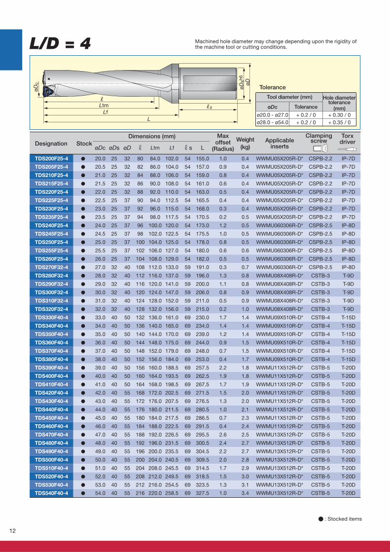
L/D = 4
L
Rs
øDsh
6
R
øDc øD
LtmLf
øDc øDs øD r Ltm Lf rs L
TDS200F25-4 ● 20.0 25 32 80 84.0 102.0 54 155.0 1.0 0.4 WWMU05X205R-D* CSPB-2.2 IP-7D
TDS205F25-4 ● 20.5 25 32 82 86.0 104.0 54 157.0 0.9 0.4 WWMU05X205R-D* CSPB-2.2 IP-7D
TDS210F25-4 ● 21.0 25 32 84 88.0 106.0 54 159.0 0.8 0.4 WWMU05X205R-D* CSPB-2.2 IP-7D
TDS215F25-4 ● 21.5 25 32 86 90.0 108.0 54 161.0 0.6 0.4 WWMU05X205R-D* CSPB-2.2 IP-7D
TDS220F25-4 ● 22.0 25 32 88 92.0 110.0 54 163.0 0.5 0.4 WWMU05X205R-D* CSPB-2.2 IP-7D
TDS225F25-4 ● 22.5 25 37 90 94.0 112.5 54 165.5 0.4 0.4 WWMU05X205R-D* CSPB-2.2 IP-7D
TDS230F25-4 ● 23.0 25 37 92 96.0 115.0 54 168.0 0.3 0.4 WWMU05X205R-D* CSPB-2.2 IP-7D
TDS235F25-4 ● 23.5 25 37 94 98.0 117.5 54 170.5 0.2 0.5 WWMU05X205R-D* CSPB-2.2 IP-7D
TDS240F25-4 ● 24.0 25 37 96 100.0 120.0 54 173.0 1.2 0.5 WWMU060306R-D* CSPB-2.5 IP-8D
TDS245F25-4 ● 24.5 25 37 98 102.0 122.5 54 175.5 1.0 0.5 WWMU060306R-D* CSPB-2.5 IP-8D
TDS250F25-4 ● 25.0 25 37 100 104.0 125.0 54 178.0 0.8 0.5 WWMU060306R-D* CSPB-2.5 IP-8D
TDS255F25-4 ● 25.5 25 37 102 106.0 127.0 54 180.0 0.6 0.6 WWMU060306R-D* CSPB-2.5 IP-8D
TDS260F25-4 ● 26.0 25 37 104 108.0 129.0 54 182.0 0.5 0.5 WWMU060306R-D* CSPB-2.5 IP-8D
TDS270F32-4 ● 27.0 32 40 108 112.0 133.0 59 191.0 0.3 0.7 WWMU060306R-D* CSPB-2.5 IP-8D
TDS280F32-4 ● 28.0 32 40 112 116.0 137.0 59 196.0 1.3 0.8 WWMU08X408R-D* CSTB-3 T-9D
TDS290F32-4 ● 29.0 32 40 116 120.0 141.0 59 200.0 1.1 0.8 WWMU08X408R-D* CSTB-3 T-9D
TDS300F32-4 ● 30.0 32 40 120 124.0 147.0 59 206.0 0.8 0.9 WWMU08X408R-D* CSTB-3 T-9D
TDS310F32-4 ● 31.0 32 40 124 128.0 152.0 59 211.0 0.5 0.9 WWMU08X408R-D* CSTB-3 T-9D
TDS320F32-4 ● 32.0 32 40 128 132.0 156.0 59 215.0 0.2 1.0 WWMU08X408R-D* CSTB-3 T-9D
TDS330F40-4 ● 33.0 40 50 132 136.0 161.0 69 230.0 1.7 1.4 WWMU09X510R-D* CSTB-4 T-15D
TDS340F40-4 ● 34.0 40 50 136 140.0 165.0 69 234.0 1.4 1.4 WWMU09X510R-D* CSTB-4 T-15D
TDS350F40-4 ● 35.0 40 50 140 144.0 170.0 69 239.0 1.2 1.4 WWMU09X510R-D* CSTB-4 T-15D
TDS360F40-4 ● 36.0 40 50 144 148.0 175.0 69 244.0 0.9 1.5 WWMU09X510R-D* CSTB-4 T-15D
TDS370F40-4 ● 37.0 40 50 148 152.0 179.0 69 248.0 0.7 1.5 WWMU09X510R-D* CSTB-4 T-15D
TDS380F40-4 ● 38.0 40 50 152 156.0 184.0 69 253.0 0.4 1.7 WWMU09X510R-D* CSTB-4 T-15D
TDS390F40-4 ● 39.0 40 50 156 160.0 188.5 69 257.5 2.2 1.8 WWMU11X512R-D* CSTB-5 T-20D
TDS400F40-4 ● 40.0 40 50 160 164.0 193.5 69 262.5 1.9 1.8 WWMU11X512R-D* CSTB-5 T-20D
TDS410F40-4 ● 41.0 40 50 164 168.0 198.5 69 267.5 1.7 1.9 WWMU11X512R-D* CSTB-5 T-20D
TDS420F40-4 ● 42.0 40 55 168 172.0 202.5 69 271.5 1.5 2.0 WWMU11X512R-D* CSTB-5 T-20D
TDS430F40-4 ● 43.0 40 55 172 176.0 207.5 69 276.5 1.3 2.0 WWMU11X512R-D* CSTB-5 T-20D
TDS440F40-4 ● 44.0 40 55 176 180.0 211.5 69 280.5 1.0 2.1 WWMU11X512R-D* CSTB-5 T-20D
TDS450F40-4 ● 45.0 40 55 180 184.0 217.5 69 286.5 0.7 2.3 WWMU11X512R-D* CSTB-5 T-20D
TDS460F40-4 ● 46.0 40 55 184 188.0 222.5 69 291.5 0.4 2.4 WWMU11X512R-D* CSTB-5 T-20D
TDS470F40-4 ● 47.0 40 55 188 192.0 226.5 69 295.5 2.6 2.5 WWMU13X512R-D* CSTB-5 T-20D
TDS480F40-4 ● 48.0 40 55 192 196.0 231.5 69 300.5 2.4 2.7 WWMU13X512R-D* CSTB-5 T-20D
TDS490F40-4 ● 49.0 40 55 196 200.0 235.5 69 304.5 2.2 2.7 WWMU13X512R-D* CSTB-5 T-20D
TDS500F40-4 ● 50.0 40 55 200 204.0 240.5 69 309.5 2.0 2.8 WWMU13X512R-D* CSTB-5 T-20D
TDS510F40-4 ● 51.0 40 55 204 208.0 245.5 69 314.5 1.7 2.9 WWMU13X512R-D* CSTB-5 T-20D
TDS520F40-4 ● 52.0 40 55 208 212.0 249.5 69 318.5 1.5 3.0 WWMU13X512R-D* CSTB-5 T-20D
TDS530F40-4 ● 53.0 40 55 212 216.0 254.5 69 323.5 1.3 3.1 WWMU13X512R-D* CSTB-5 T-20D
TDS540F40-4 ● 54.0 40 55 216 220.0 258.5 69 327.5 1.0 3.4 WWMU13X512R-D* CSTB-5 T-20D
(mm)øDc
ø20.0 - ø27.0 + 0.2 / 0 + 0.30 / 0
ø28.0 - ø54.0 + 0.2 / 0 + 0.35 / 0
Dimensions (mm)Applicable
inserts
Maxoffset
(Radius)
Weight
(kg)
Clamping screw
Torx driver Designation Stock
� : Stocked items
Tool diameter (mm)
Tolerance
Hole diametertolerance
Tolerance
Machined hole diameter may change depending upon the rigidity of the machine tool or cutting conditions.
13
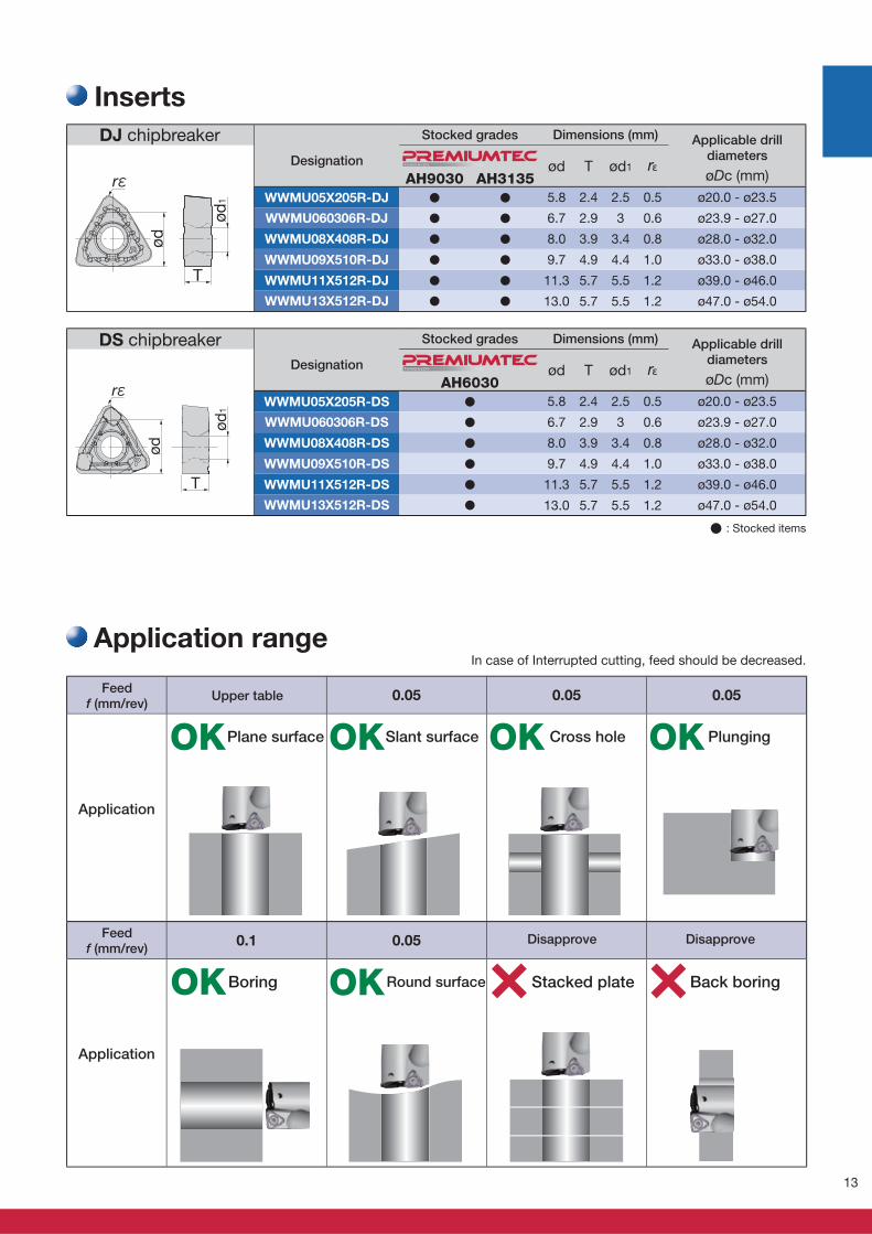
øDc (mm)AH9030 AH3135ød T ød1 rε
WWMU05X205R-DJ � � 5.8 2.4 2.5 0.5 ø20.0 - ø23.5
WWMU060306R-DJ � � 6.7 2.9 3 0.6 ø23.9 - ø27.0
WWMU08X408R-DJ � � 8.0 3.9 3.4 0.8 ø28.0 - ø32.0
WWMU09X510R-DJ � � 9.7 4.9 4.4 1.0 ø33.0 - ø38.0
WWMU11X512R-DJ � � 11.3 5.7 5.5 1.2 ø39.0 - ø46.0
WWMU13X512R-DJ � � 13.0 5.7 5.5 1.2 ø47.0 - ø54.0
rε
T
ød1
ødT U N G A LOY
øDc (mm)AH6030ød T ød1 rε
WWMU05X205R-DS � 5.8 2.4 2.5 0.5 ø20.0 - ø23.5
WWMU060306R-DS � 6.7 2.9 3 0.6 ø23.9 - ø27.0
WWMU08X408R-DS � 8.0 3.9 3.4 0.8 ø28.0 - ø32.0
WWMU09X510R-DS � 9.7 4.9 4.4 1.0 ø33.0 - ø38.0
WWMU11X512R-DS � 11.3 5.7 5.5 1.2 ø39.0 - ø46.0
WWMU13X512R-DS � 13.0 5.7 5.5 1.2 ø47.0 - ø54.0
T
ød1
ød
rεT U N G A LOY
0.05 0.05 0.05
0.1 0.05
OK
OK
OK
OK
OK OK
� : Stocked items
Inserts
DJ chipbreaker
Designation
Stocked grades Dimensions (mm) Applicable drilldiameters
Designation
Stocked grades Dimensions (mm) Applicable drilldiameters
DS chipbreaker
Application range
Application
Application
Feedf (mm/rev)
Feedf (mm/rev)
Upper table
Plane surface Slant surface Cross hole Plunging
Boring Round surface Stacked plate Back boring
In case of Interrupted cutting, feed should be decreased.
Disapprove Disapprove
14
(N·m) (N·m)GH130
TDXCF280L30
~
TDXCF540L30XHGX090700R-45A � CSPB-4S 3.5 CM8X1.25X20-A 8.0 T-15D P-5
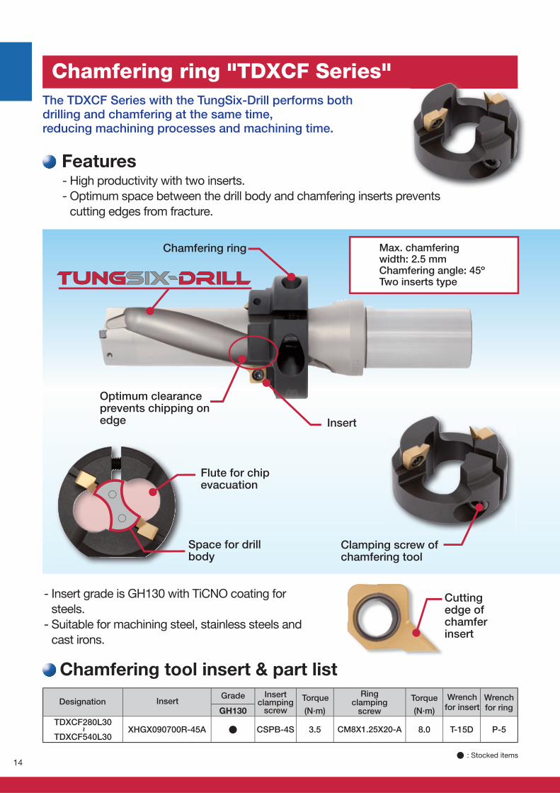
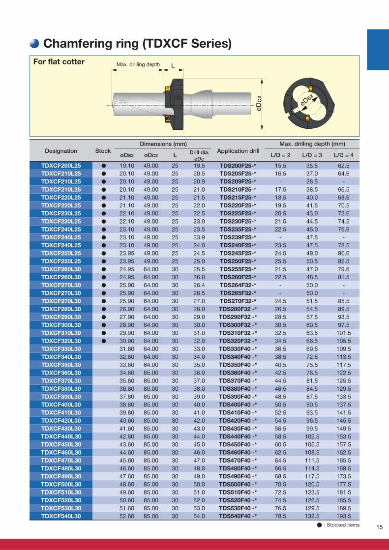
Chamfering ring "TDXCF Series"
Features- High productivity with two inserts.
- Optimum space between the drill body and chamfering inserts prevents
cutting edges from fracture.
The TDXCF Series with the TungSix-Drill performs both drilling and chamfering at the same time, reducing machining processes and machining time.
- Insert grade is GH130 with TiCNO coating for
steels.
- Suitable for machining steel, stainless steels and
cast irons.
Cutting edge of chamfer insert
Clamping screw of chamfering tool
Flute for chip evacuation
Insert
Optimum clearance prevents chipping on edge
Chamfering ring Max. chamfering width: 2.5 mmChamfering angle: 45ºTwo inserts type
Space for drill body
Chamfering tool insert & part list
Designation Insert Grade Insert
clampingscrew
Torque TorqueRing
clampingscrew
Wrenchfor insert
Wrenchfor ring
� : Stocked items
15
øDs2 øDc2 LøDc
L/D = 2 L/D = 3 L/D = 4
TDXCF200L25 ● 19.10 49.00 25 19.5 TDS200F25-* 15.5 35.5 62.5
TDXCF210L25 ● 20.10 49.00 25 20.5 TDS205F25-* 16.5 37.0 64.6
TDXCF210L25 ● 20.10 49.00 25 20.9 TDS209F25-* - 38.5 -
TDXCF210L25 ● 20.10 49.00 25 21.0 TDS210F25-* 17.5 38.5 66.5
TDXCF220L25 ● 21.10 49.00 25 21.5 TDS215F25-* 18.5 40.0 68.6
TDXCF220L25 ● 21.10 49.00 25 22.0 TDS220F25-* 19.5 41.5 70.5
TDXCF230L25 ● 22.10 49.00 25 22.5 TDS225F25-* 20.5 43.0 72.6
TDXCF230L25 ● 22.10 49.00 25 23.0 TDS230F25-* 21.5 44.5 74.5
TDXCF240L25 ● 23.10 49.00 25 23.5 TDS235F25-* 22.5 46.0 76.6
TDXCF240L25 ● 23.10 49.00 25 23.9 TDS239F25-* - 47.5 -
TDXCF240L25 ● 23.10 49.00 25 24.0 TDS240F25-* 23.5 47.5 78.5
TDXCF250L25 ● 23.95 49.00 25 24.5 TDS245F25-* 24.5 49.0 80.6
TDXCF250L25 ● 23.95 49.00 25 25.0 TDS250F25-* 25.5 50.5 82.5
TDXCF260L30 ● 24.95 64.00 30 25.5 TDS255F25-* 21.5 47.0 79.6
TDXCF260L30 ● 24.95 64.00 30 26.0 TDS260F25-* 22.5 48.5 81.5
TDXCF270L30 ● 25.90 64.00 30 26.4 TDS264F32-* - 50.0 -
TDXCF270L30 ● 25.90 64.00 30 26.5 TDS265F32-* - 50.0 -
TDXCF270L30 ● 25.90 64.00 30 27.0 TDS270F32-* 24.5 51.5 85.5
TDXCF280L30 ● 26.90 64.00 30 28.0 TDS280F32 -* 26.5 54.5 89.5
TDXCF290L30 ● 27.90 64.00 30 29.0 TDS290F32 -* 28.5 57.5 93.5
TDXCF300L30 ● 28.90 64.00 30 30.0 TDS300F32 -* 30.5 60.5 97.5
TDXCF310L30 ● 29.90 64.00 30 31.0 TDS310F32 -* 32.5 63.5 101.5
TDXCF320L30 ● 30.90 64.00 30 32.0 TDS320F32 -* 34.5 66.5 105.5
TDXCF330L30 31.80 64.00 30 33.0 TDS330F40 -* 36.5 69.5 109.5
TDXCF340L30 32.80 64.00 30 34.0 TDS340F40 -* 38.5 72.5 113.5
TDXCF350L30 33.80 64.00 30 35.0 TDS350F40 -* 40.5 75.5 117.5
TDXCF360L30 34.80 85.00 30 36.0 TDS360F40 -* 42.5 78.5 122.5
TDXCF370L30 35.80 85.00 30 37.0 TDS370F40 -* 44.5 81.5 125.5
TDXCF380L30 36.80 85.00 30 38.0 TDS380F40 -* 46.5 84.5 129.5
TDXCF390L30 37.80 85.00 30 39.0 TDS390F40 -* 48.5 87.5 133.5
TDXCF400L30 38.80 85.00 30 40.0 TDS400F40 -* 50.5 90.5 137.5
TDXCF410L30 39.80 85.00 30 41.0 TDS410F40 -* 52.5 93.5 141.5
TDXCF420L30 40.60 85.00 30 42.0 TDS420F40 -* 54.5 96.5 145.5
TDXCF430L30 41.60 85.00 30 43.0 TDS430F40 -* 56.5 99.5 149.5
TDXCF440L30 42.60 85.00 30 44.0 TDS440F40 -* 58.5 102.5 153.5
TDXCF450L30 43.60 85.00 30 45.0 TDS450F40 -* 60.5 105.5 157.5
TDXCF460L30 44.60 85.00 30 46.0 TDS460F40 -* 62.5 108.5 162.5
TDXCF470L30 45.60 85.00 30 47.0 TDS470F40 -* 64.5 111.5 165.5
TDXCF480L30 46.60 85.00 30 48.0 TDS480F40 -* 66.5 114.5 169.5
TDXCF490L30 47.60 85.00 30 49.0 TDS490F40 -* 68.5 117.5 173.5
TDXCF500L30 48.60 85.00 30 50.0 TDS500F40 -* 70.5 120.5 177.5
TDXCF510L30 49.60 85.00 30 51.0 TDS510F40 -* 72.5 123.5 181.5
TDXCF520L30 50.60 85.00 30 52.0 TDS520F40 -* 74.5 126.5 185.5
TDXCF530L30 51.60 85.00 30 53.0 TDS530F40 -* 76.5 129.5 189.5
TDXCF540L30 52.60 85.00 30 54.0 TDS540F40 -* 78.5 132.5 193.5
Max. drilling depth
Chamfering ring (TDXCF Series)
Designation Stock Application drillDrill dia.
Max. drilling depth (mm)Dimensions (mm)
� : Stocked items
For fl at cotter
16
OK
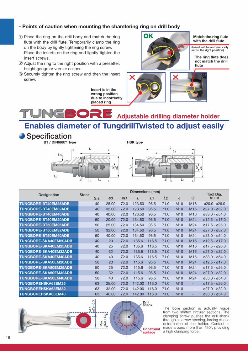
S.s. ød øD L L1 L2 J G
TUNGBORE-BT40EM25ADB 40 25.00 72.0 123.50 96.5 71.0 M10 M16 ø20.0- ø26.0
TUNGBORE-BT40EM32ADB 40 32.00 72.0 123.50 96.5 71.0 M10 M16 ø27.0 - ø32.0
TUNGBORE-BT40EM40ADB 40 40.00 72.0 123.50 96.5 71.0 M10 M16 ø33.0 - ø54.0
TUNGBORE-BT50EM20ADB 50 20.00 72.0 134.50 96.5 71.0 M10 M24 ø12.5 - ø17.0
TUNGBORE-BT50EM25ADB 50 25.00 72.0 134.50 96.5 71.0 M10 M24 ø17.5 - ø26.0
TUNGBORE-BT50EM32ADB 50 32.00 72.0 134.50 96.5 71.0 M10 M24 ø27.0 - ø32.0
TUNGBORE-BT50EM40ADB 50 40.00 72.0 134.50 96.5 71.0 M10 M24 ø33.0 - ø54.0
TUNGBORE-SKA40EM20ADB 40 20 72.0 135.6 116.5 71.0 M10 M16 ø12.5 - ø17.0
TUNGBORE-SKA40EM25ADB 40 25 72.0 135.6 116.5 71.0 M10 M16 ø17.5 - ø26.0
TUNGBORE-SKA40EM32ADB 40 32 72.0 135.6 116.5 71.0 M10 M16 ø27.0 - ø32.0
TUNGBORE-SKA40EM40ADB 40 40 72.0 135.6 116.5 71.0 M10 M16 ø33.0 - ø54.0
TUNGBORE-SKA50EM20ADB 50 20 72.0 115.6 96.5 71.0 M10 M24 ø12.5 - ø17.0
TUNGBORE-SKA50EM25ADB 50 25 72.0 115.6 96.5 71.0 M10 M24 ø17.5 - ø26.0
TUNGBORE-SKA50EM32ADB 50 32 72.0 115.6 96.5 71.0 M10 M24 ø27.0 - ø32.0
TUNGBORE-SKA50EM40ADB 50 40 72.0 115.6 96.5 71.0 M10 M24 ø33.0 - ø54.0
TUNGBOREHSKA63EM25 63 25.00 72.0 142.00 116.0 71.0 M10 - ø17.5 - ø26.0
TUNGBOREHSKA63EM32 63 32.00 72.0 142.00 116.0 71.0 M10 - ø27.0 - ø32.0
TUNGBOREHSKA63EM40 63 40.00 72.0 142.00 116.0 71.0 M10 - ø33.0 - ø54.0
- Points of caution when mounting the chamfering ring on drill body
Match the ring fl ute with the drill fl ute
(Insert will be automatically set to the right position)
The ring fl ute does not match the drill fl ute
Insert is in the wrong position due to incorrectly placed ring
Place the ring on the drill body and match the ring
fl ute with the drill fl ute. Temporarily clamp the ring
on the body by lightly tightening the ring screw.
Place the inserts on the ring and lightly tighten the
insert screws.
Adjust the ring to the right position with a presetter,
height gauge or vernier caliper.
Securely tighten the ring screw and then the insert
screw.
Dimensions (mm)Designation Stock Tool Dia.
(mm)
Specifi cationBT / DIN69871 type HSK type
The bore section is actually made from two shifted circular sections. The clamping screw pushes the drill shank through a narrow opening, forcing elastic deformation of the holder. Contact is made around more than 180°, providing a high clamping force.
Drillshank
Constraintsurface
Adjustable drilling diameter holder
Enables diameter of TungdrillTwisted to adjust easily
øø
JG
S.s.
2
1
øDødS.s
.
J L2
LL1
Max.
øD
c +
1.3
Min
.
øD
c -
0.3
17
20.0 20.0 21.3
20.5 20.5 21.8
20.9 20.9 22.2
21.0 21.0 22.3
21.5 21.5 22.7
22.0 22.0 23.0
22.5 22.5 23.3
23.0 23.0 23.6
23.5 23.5 23.9
23.9 23.9 25.2
24.0 24.0 25.3
24.5 24.5 25.8
25.0 25.0 26.3
25.5 25.5 26.7
26.0 26.0 27.0
26.4 26.4 27.2
26.5 26.5 27.3
27.0 27.0 27.6
28.0 28.0 29.3
29.0 29.0 30.3
30.0 30.0 31.3
31.0 31.0 32.0
32.0 32.0 32.4
33 33 34.3
34 34 35.3
35 35 36.3
36 36 37.3
37 37 38.3
38 38 38.8
39 39 40.3
40 40 41.3
41 41 42.3
42 42 43.3
43 43 44.3
44 44 45.3
45 45 46.3
46 46 46.8
47 47 48.3
48 48 49.3
49 49 50.3
50 50 51.3
51 51 52.3
52 52 53.3
53 53 54.3
54 54 55.3
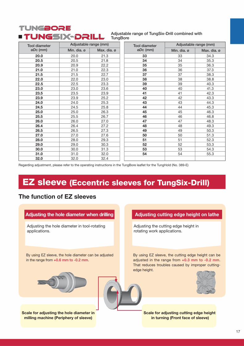
The function of EZ sleeves
Adjusting the hole diameter when drilling
Adjusting the hole diameter in tool-rotating
applications.
By using EZ sleeve, the hole diameter can be adjusted
in the range from +0.6 mm to -0.2 mm.
Adjusting cutting edge height on lathe
Adjusting the cutting edge height in
rotating work applications.
By using EZ sleeve, the cutting edge height can be
adjusted in the range from +0.3 mm to -0.2 mm.
That reduces troubles caused by improper cutting-
edge height.
Scale for adjusting the hole diameter in
milling machine (Periphery of sleeve)
Scale for adjusting cutting edge height
in turning (Front face of sleeve)
EZ sleeve (Eccentric sleeves for TungSix-Drill)
Adjustable range of TungSix-Drill combined with TungBore
Regarding adjustment, please refer to the operating instructions in the TungBore leafl et for the TungHold (No. 389-E)
Tool diameterøDc (mm)
Adjustable range (mm)
Min. dia. ø Max. dia. øTool diameter
øDc (mm)
Adjustable range (mm)
Min. dia. ø Max. dia. ø
18
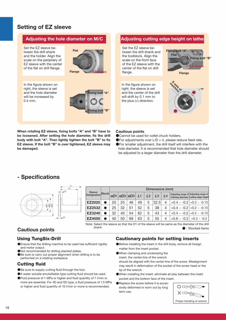
øD1 øD2 øD3 L1 L2 L3 L4
EZ2025 ● 20 25 46 49 5 32.5 4 +0.4 ~ -0.2 +0.2 ~ -0.15
EZ2532 ● 25 32 51 52 5 38 4 +0.4 ~ -0.2 +0.2 ~ -0.15
EZ3240 ● 32 40 54 62 5 43 4 +0.4 ~ -0.2 +0.2 ~ -0.15
EZ4050 ● 40 50 69 63 5 55 4 +0.6 ~ -0.2 +0.3 ~ -0.2
øD1
øD2
øD3
L1
L2
L3
L4
(+)
(-)
+0.4+0.2
●Ensure that the drilling machine to be used has suffi cient rigidity and motor output.●Not recommended for drilling stacked plates.●Be sure to carry out proper alignment when drilling is to be
performed on a rotating workpiece.
●Before installing the insert in the drill body, remove all foreign
matter from the insert pocket.
●When clamping and unclamping the
insert, the center-line of the wrench
should be aligned with the center-line of the screw. Misalignment
may result in deformation of the socket of the screw head or the
tip of the wrench.
●When installing the insert, eliminate all play between the insert
pocket and the bottom face of the insert.
●Replace the screw before it is exces-
sively deformed or worn out by long
term use.
●Be sure to supply cutting fl uid through the tool.
●A water soluble emulsifi able type cutting fl uid should be used.
●Fluid pressure of 1 MPa or higher and fl uid quantity of 7 l/min or
more are essential. For 4D and 5D type, a fl uid pressure of 1.5 MPa
or higher and fl uid quantity of 10 l/min or more is recommended.
Using TungSix-Drill
Cutting fl uid
Cautionary points for setting inserts
- Specifi cations
Cautious points
Setting of EZ sleeve
Adjusting the hole diameter on M/C Adjusting cutting edge height on lathe
In the fi gure shown on right, the sleeve is set and the hole diameter will be increased by 0.4 mm.
Set the EZ sleeve be-tween the drill shank and the holder. Align the scale on the periphery of EZ sleeve with the center of the fl at on drill fl ange.
Set the EZ sleeve be-tween the drill shank and the toolblock. Align the scale on the front face of the EZ sleeve with the center of the fl at on drill fl ange.
In the fi gure shown on right, the sleeve is set and the center of the drill will shift by 0.1 mm to the plus (+) direction.
EZ sleeve
Note: Select the sleeve so that the D1 of the sleeve will be same as the diameter of the drill shank.
Proper handling of wrench
Cautious points●Cannot be used for collet chuck holders.
●For adjustments over L/D = 4, please reduce feed rate.
●For smaller adjustment, the drill itself will interfere with the
hole diameter. It is recommended that hole diameter should
be adjusted to a larger diameter than the drill diameter.
When rotating EZ sleeve, fi xing bolts “A” and “B” have to
be loosened. After setting the hole diameter, fi x the drill
body with bolt “A”. Then lightly tighten the bolt ”B” to fi x
EZ sleeve. If the bolt “B” is over tightened, EZ sleeve may
be damaged.
Fixing bolt “A”
Fixing bolt “B”
X-axis of
machine
Flat
Flange
Fixing bolt “A”
Flat
Flange
EZ sleeve
Fixing bolt “B”
Sleeve Stock Designation Adjusting range of
fi nishing diameter
Adjusting range of
cutting edge height
Dimensions (mm)
● : Stocked items
19
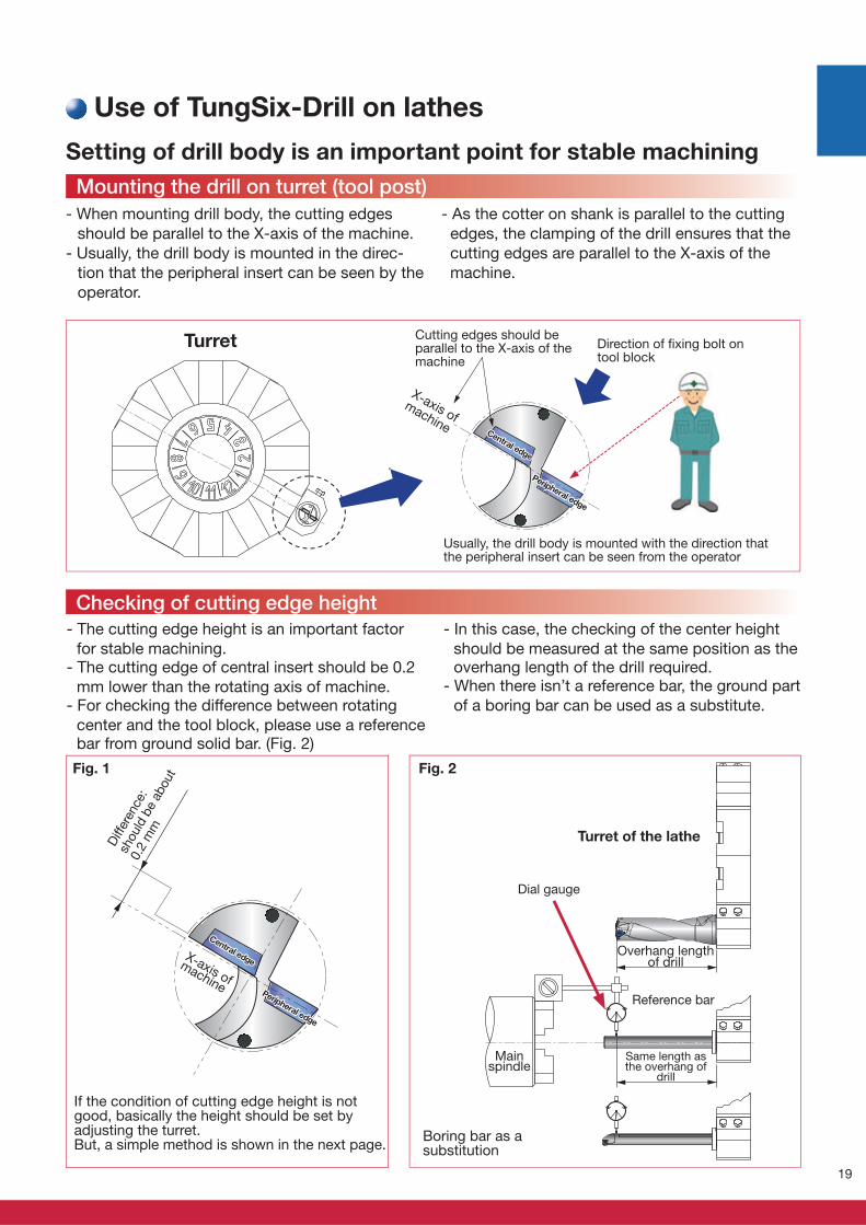
- When mounting drill body, the cutting edges
should be parallel to the X-axis of the machine.
- Usually, the drill body is mounted in the direc-
tion that the peripheral insert can be seen by the
operator.
Setting of drill body is an important point for stable machining
Direction of fi xing bolt on tool block
Usually, the drill body is mounted with the direction that the peripheral insert can be seen from the operator
- The cutting edge height is an important factor
for stable machining.- The cutting edge of central insert should be 0.2
mm lower than the rotating axis of machine.- For checking the difference between rotating
center and the tool block, please use a reference bar from ground solid bar. (Fig. 2)
Mainspindle
If the condition of cutting edge height is not good, basically the height should be set byadjusting the turret.But, a simple method is shown in the next page.
Fig. 1 Fig. 2
Dial gauge
Overhang length of drill
Same length as the overhang of
drill
Reference bar
Turret of the lathe
Boring bar as asubstitution
Cutting edges should be parallel to the X-axis of the machine
X-axis of machine
Central edge
Central edge
Peripheral edge
Peripheral edge
Turret
Diff
eren
ce:
shoul
d b
e ab
out
0.2
mm
Mounting the drill on turret (tool post)
Checking of cutting edge height
Use of TungSix-Drill on lathes
X-axis of
machine
Central edge
Central edge
Peripheral edge
Peripheral edge
- As the cotter on shank is parallel to the cutting
edges, the clamping of the drill ensures that the
cutting edges are parallel to the X-axis of the
machine.
- In this case, the checking of the center height
should be measured at the same position as the overhang length of the drill required.
- When there isn’t a reference bar, the ground part
of a boring bar can be used as a substitute.
20
1
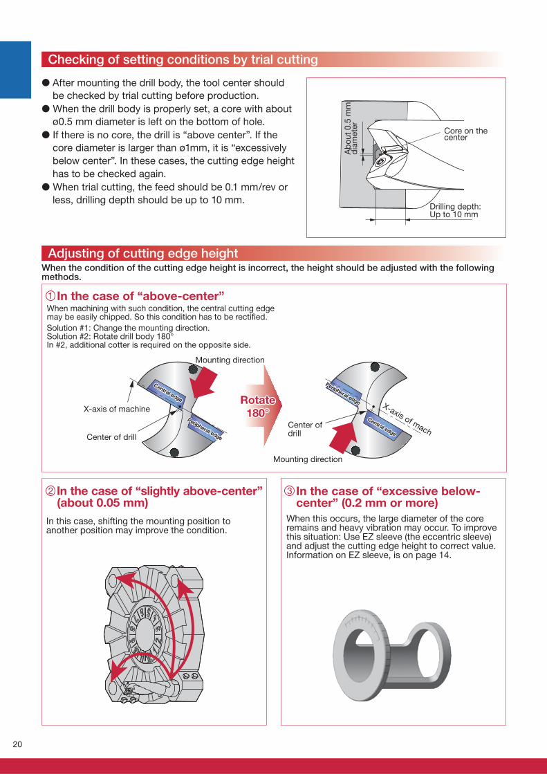
2 3
When the condition of the cutting edge height is incorrect, the height should be adjusted with the followingmethods.
When machining with such condition, the central cutting edge may be easily chipped. So this condition has to be rectifi ed.
Solution #1: Change the mounting direction. Solution #2: Rotate drill body 180°In #2, additional cotter is required on the opposite side.
In this case, shifting the mounting position to another position may improve the condition.
When this occurs, the large diameter of the core remains and heavy vibration may occur. To improve this situation: Use EZ sleeve (the eccentric sleeve) and adjust the cutting edge height to correct value. Information on EZ sleeve, is on page 14.
In the case of “slightly above-center” (about 0.05 mm)
In the case of “excessive below-center” (0.2 mm or more)
In the case of “above-center”
Core on the center
Drilling depth: Up to 10 mm
Ab
ou
t 0
.5 m
m
dia
mete
rMounting direction
Mounting direction
Center of drill
Rotate Rotate 180°180°
Checking of setting conditions by trial cutting
Adjusting of cutting edge height
� After mounting the drill body, the tool center should
be checked by trial cutting before production.
� When the drill body is properly set, a core with about
ø0.5 mm diameter is left on the bottom of hole.
� If there is no core, the drill is “above center”. If the
core diameter is larger than ø1mm, it is “excessively
below center”. In these cases, the cutting edge height
has to be checked again.
� When trial cutting, the feed should be 0.1 mm/rev or
less, drilling depth should be up to 10 mm.
X-axis of machineX-axis of mach
Center of drill
Central edge
Central edge
Central edge
Central edge
Peripheral edge
Peripheral edge
Peripheral edge
Peripheral edge
21
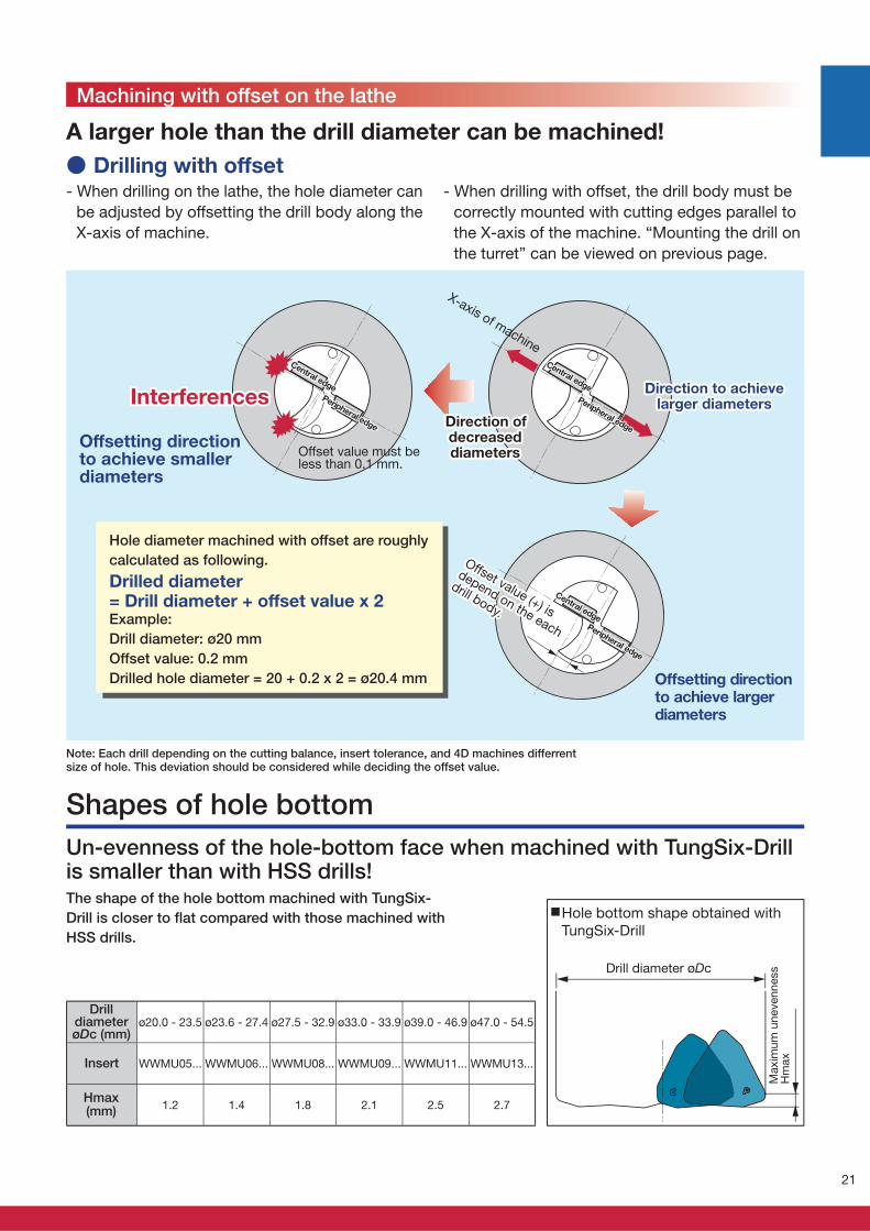
ø20.0 - 23.5 ø23.6 - 27.4 ø27.5 - 32.9 ø33.0 - 33.9 ø39.0 - 46.9 ø47.0 - 54.5
WWMU05... WWMU06... WWMU08... WWMU09... WWMU11... WWMU13...
1.2 1.4 1.8 2.1 2.5 2.7
A larger hole than the drill diameter can be machined!
- When drilling on the lathe, the hole diameter can
be adjusted by offsetting the drill body along the
X-axis of machine.
Offsetting direction to achieve smaller diameters
Offsetting direction to achieve larger diameters
Hole diameter machined with offset are roughly
calculated as following.
Drilled diameter = Drill diameter + offset value x 2Example:
Drill diameter: ø20 mm
Offset value: 0.2 mm
Drilled hole diameter = 20 + 0.2 x 2 = ø20.4 mm
● Drilling with offset
InterferencesInterferences
Offset value must be less than 0.1 mm.
Direction to achieve Direction to achieve larger diameterslarger diameters
Direction of Direction of decreased decreased diametersdiameters
Un-evenness of the hole-bottom face when machined with TungSix-Drill is smaller than with HSS drills!The shape of the hole bottom machined with TungSix-
Drill is closer to fl at compared with those machined with
HSS drills.
Note: Each drill depending on the cutting balance, insert tolerance, and 4D machines differrent size of hole. This deviation should be considered while deciding the offset value.
DrilldiameterøDc (mm)
Drill diameter øDc
Hole bottom shape obtained with
TungSix-Drill
Maxim
um
unevenness
Hm
ax
Shapes of hole bottom
Machining with offset on the lathe
X-axis of machine
Offset value (+) is
Offset value (+) is
depend on the each
depend on the each
drill body.
drill body.
Central edge
Central edge
Central edge
Central edge
Peripheral edge
Peripheral edge
Peripheral edge
Peripheral edge
Central edge
Central edgePeripheral edge
Peripheral edge
- When drilling with offset, the drill body must be
correctly mounted with cutting edges parallel to
the X-axis of the machine. “Mounting the drill on
the turret” can be viewed on previous page.
Hmax (mm)
Insert
22
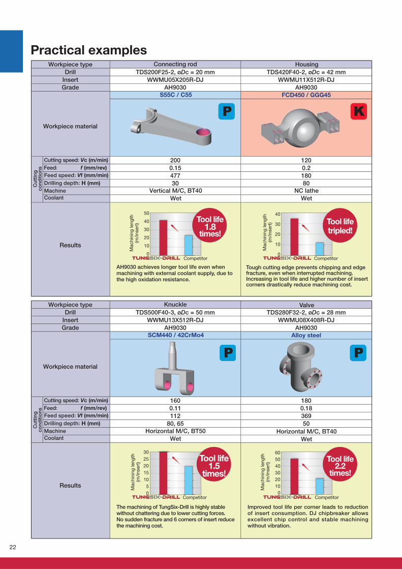
TDS200F25-2, øDc = 20 mm TDS420F40-2, øDc = 42 mm
WWMU05X205R-DJ WWMU11X512R-DJ
AH9030 AH9030
200 120
0.15 0.2
477 180
30 80
50
40
30
20
10
0
40
30
20
10
0
TDS500F40-3, øDc = 50 mm TDS280F32-2, øDc = 28 mm
WWMU13X512R-DJ WWMU08X408R-DJ
AH9030 AH9030
160 180
0.11 0.18
112 369
80, 65 50
30
25
20
15
10
5
0
60
50
40
30
20
10
0
Practical examples
Vertical M/C, BT40
Wet
Connecting rod
S55C / C55
Workpiece type
Drill
Insert
Grade
Workpiece material
Cutting speed: Vc (m/min)
Feed: f (mm/rev)
Feed speed: Vf (mm/min)
Drilling depth: H (mm)
Machine
Coolant
Results
Cu
ttin
gco
nd
itio
ns
NC lathe
Wet
Horizontal M/C, BT50
Wet
Knuckle
SCM440 / 42CrMo4
Workpiece type
Drill
Insert
Grade
Workpiece material
Cutting speed: Vc (m/min)
Feed: f (mm/rev)
Feed speed: Vf (mm/min)
Drilling depth: H (mm)
Machine
Coolant
Results
Cu
ttin
gco
nd
itio
ns
Horizontal M/C, BT40
Wet
AH9030 achieves longer tool life even when machining with external coolant supply, due to the high oxidation resistance.
Tool life 1.8
times!
Competitor
Mach
inin
g len
gth
(m
/in
sert
)
Tough cutting edge prevents chipping and edge fracture, even when interrupted machining. Increasing in tool life and higher number of insert corners drastically reduce machining cost.
Tool life tripled!
Competitor
Mach
inin
g len
gth
(m
/in
sert
)
FCD450 / GGG45
Housing
Valve
Alloy steel
The machining of TungSix-Drill is highly stable without chattering due to lower cutting forces. No sudden fracture and 6 corners of insert reduce the machining cost.
Tool life 1.5
times!
Competitor
Mach
inin
g len
gth
(m
/in
sert
)
Improved tool life per corner leads to reduction of insert consumption. DJ chipbreaker allows excellent chip control and stable machining without vibration.
Competitor
Mach
inin
g len
gth
(m
/in
sert
) Tool life 2.2
times!
23
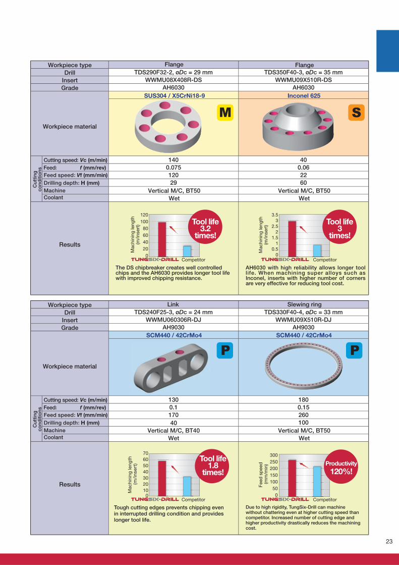
TDS290F32-2, øDc = 29 mm TDS350F40-3, øDc = 35 mm
WWMU08X408R-DS WWMU09X510R-DS
AH6030 AH6030
140 40
0.075 0.06
120 22
29 60
120
100
80
60
40
20
0
3.5
3
2.5
2
1.5
1
0.5
0
TDS240F25-3, øDc = 24 mm TDS330F40-4, øDc = 33 mm
WWMU060306R-DJ WWMU09X510R-DJ
AH9030 AH9030
130 180
0.1 0.15
170 260
100
70
60
50
40
30
20
100
300
250
200
150
100
50
0
Vertical M/C, BT50
Wet
Flange
SUS304 / X5CrNi18-9
Workpiece type
Drill
Insert
Grade
Workpiece material
Cutting speed: Vc (m/min)
Feed: f (mm/rev)
Feed speed: Vf (mm/min)
Drilling depth: H (mm)
Machine
Coolant
Results
Cu
ttin
gco
nd
itio
ns
Vertical M/C, BT50
Wet
The DS chipbreaker creates well controlled chips and the AH6030 provides longer tool life with improved chipping resistance.
Flange
Inconel 625
Tool life 3.2
times!
Tool life 1.8
times!
Competitor
Mach
inin
g len
gth
(m
/in
sert
)
AH6030 with high reliability allows longer tool life. When machining super alloys such as Inconel, inserts with higher number of corners are very effective for reducing tool cost.
Tool life 3
times!
CompetitorM
ach
inin
g len
gth
(m
/in
sert
)
Workpiece type
Drill
Insert
Grade
Workpiece material
Cutting speed: Vc (m/min)
Feed: f (mm/rev)
Feed speed: Vf (mm/min)
Drilling depth: H (mm)
Machine
Coolant
Results
Cu
ttin
gco
nd
itio
ns
Vertical M/C, BT50
Wet
40
Vertical M/C, BT40
Wet
Slewing ringLink
SCM440 / 42CrMo4SCM440 / 42CrMo4
Due to high rigidity, TungSix-Drill can machine without chattering even at higher cutting speed than competitor. Increased number of cutting edge and higher productivity drastically reduces the machining cost.
Tough cutting edges prevents chipping even in interrupted drilling condition and provides longer tool life.
Productivity
120%!
CompetitorCompetitor
Feed
sp
eed
(m
m/m
in)
Mach
inin
g le
ng
th (
m/i
nse
rt)

www.youtube.com/tungaloycorporation
Distributed by:
Sep. 2017 (TJ)Produced from Recycled paper
To see this product in action visit:
D O W N L O A DDr. Carbide App
w w w . t u n g a l o y . c o m
f a c e b o o k . c o m / t u n g a l o y j a p a nt w i t t e r . c o m / t u n g a l o y j a p a n
follow us at:
AS9100 Certified780062015.11.04
ISO14001 CertifiedEC97J11231997.11.26
Tungaloy Scandinavia ABBultgatan 38442 40 Kungälv, SwedenPhone: +46-462119200 www.tungaloy.se
Tungaloy Rus, LLCAndropova avenue, h.18/7, 11 fl oor, offi ce 3, 115432, Moscow, RussiaPhone: +7-499-683-01-80 Fax: +7-499-683-01-81www.tungaloy.co.jp/ru
Tungaloy East LLC620075, Russian Federation, Sverdlovsk Region, Ekaterinburg, Mamina-Sibiryaka str., bldg. 101, room 202Phone: +7-343-286-48-23/24Fax: +7-912-284-91-69www.tungaloy.co.jp/rue
Tungaloy Polska Sp. z o.o.ul. Genewska 24 03-963 Warszawa, PolandPhone: +48-22-617-0890 Fax: +48-22-617-0890www.tungaloy.co.jp/pl
Tungaloy U.K. LtdThe Technology Centre, Wolverhampton Science Park Glaisher Drive, WolverhamptonWest Midlands WV10 9RU, UKPhone: +44 121 4000 231 Fax: +44 121 270 9694 www.tungaloy.co.jp/uk [email protected]
Tungaloy Hungary KftErzsébet királyné útja 125 H-1142 Budapest, Hungary Phone: +36 1 781-6846 Fax: +36 1 781-6866www.tungaloy.co.jp/hu [email protected]
Tungaloy TurkeyDudullu OSB 4. Cad No:4 34776 Ümraniye Istanbul, TURKEY Phone: +90 216 540 04 67 Fax: +90 216 540 04 87www.tungaloy.com.tr [email protected]
Tungaloy Benelux b.v.Tjalk 70NL-2411 NZ Bodegraven, Netherlands Phone: +31 172 630 420 Fax: +31 172 630 429www.tungaloy-benelux.com
Tungaloy CroatiaJosipa Kozarca 410432 Bregana, Croatia Phone: +385 1 3326 604 Fax: +385 1 3327 683www.tungaloy.hr
Tungaloy Cutting Tool (Shanghai) Co.,Ltd.Rm No 401 No.88 Zhabei Jiangchang No.3 RdShanghai 200436, ChinaPhone: +86-21-3632-1880 Fax: +86-21-3621-1918www.tungaloy.co.jp/tcts
Tungaloy Cutting Tool (Thailand) Co.,Ltd.Interlink tower 4th Fl. 1858/5-7 Bangna-Trad Road km.5 Bangna, Bangna, Bangkok 10260ThailandPhone: +66-2-751-5711 Fax: +66-2-751-5715www.tungaloy.co.th
Tungaloy Singapore (Pte.), Ltd.62 Ubi Road 1, #06-11 Oxley BizHub 2Singapore 408734Phone: +65-6391-1833 Fax: +65-6299-4557www.tungaloy.co.jp/tspl
Tungaloy Vietnam LE 04-38, Lexington Residence 67 Mai Chi Tho, Dist. 2, Ho Chi Minh City, Vietnam Phone: +84-8-37406660 Fax: +84-8-37406662 www.tungaloy.co.jp/tspl
Tungaloy India Pvt. Ltd.Indiabulls Finance Centre,Unit # 902-A, 9th Floor,Tower 1, Senapati Bapat Marg,Elphinstone Road (West),Mumbai -400013, IndiaPhone: +91-22-6124-8804 Fax: +91-22-6124-8899www.tungaloy.co.jp/in
Tungaloy Korea Co., Ltd#1312, Byucksan Digital Valley 5-chaBeotkkot-ro 244, Geumcheon-gu153-788 Seoul, KoreaPhone: +82-2-2621-6161 Fax: +82-2-6393-8952www.tungaloy.co.jp/kr
Tungaloy Malaysia Sdn Bhd50 K-2, Kelana Mall, Jalan SS6/14Kelana Jaya, 47301 Petaling Jaya, Selangor Darul Ehsan MalaysiaPhone: +603-7805-3222 Fax: +603-7804-8563www.tungaloy.co.jp/my
Tungaloy Australia Pty LtdPO Box 2232, Rowville, Victoria 3178, AustraliaPhone: +61-3-9755-8147 Fax: +61-3-9755-6070www.tungaloy.com.au
PT. Tungaloy IndonesiaKompleks Grand Wisata Block AA-10 No.3-5 Cibitung Bekasi 17510, IndonesiaPhone: +62-21-8261-5808 Fax: +62-21-8261-5809www.tungaloy.co.jp/id
Tungaloy Corporation (Head offi ce)11-1 Yoshima-KogyodanchiIwaki-city, Fukushima, 970-1144 JapanPhone: +81-246-36-8501 Fax: +81-246-36-8542www.tungaloy.co.jp
Tungaloy America, Inc.3726 N Ventura DriveArlington Heights,IL 60004, U.S.A.Phone: +1-888-554-8394 Fax: +1-888-554-8392www.tungaloyamerica.com
Tungaloy Canada 432 Elgin St. Unit 3 Brantford, Ontario N3S 7P7, Canada Phone: +1-519-758-5779 Fax: +1-519-758-5791 www.tungaloy.co.jp/ca
Tungaloy de Mexico S.A.C Los Arellano 113, Parque Industrial Siglo XXIAguascalientes, AGS, Mexico 20290Phone: +52-449-929-5410 Fax: +52-449-929-5411www.tungaloy.co.jp/mx
Tungaloy do Brasil Ltda.Avd. Independencia N4158 Residencial Flora13280-000 Vinhedo, São Paulo, BrasilPhone: +55-19-38262757 Fax: +55-19-38262757www.tungaloy.com/br
Tungaloy Germany GmbHAn der Alten Ziegelei 1D-40789 Monheim, GermanyPhone: +49-2173-90420-0 Fax: +49-2173-90420-19www.tungaloy.de
Tungaloy France S.A.S.ZA Courtaboeuf - Le Rio1 rue de la Terre de feuF-91952 Courtaboeuf Cedex, FrancePhone: +33-1-6486-4300 Fax: +33-1-6907-7817www.tungaloy.fr
Tungaloy Italia S.r.I.Via E. Andolfato 10I-20126 Milano, ItalyPhone: +39-02-252012-1 Fax: +39-02-252012-65www.tungaloy.it
Tungaloy Czech s.r.o.Turanka 115CZ-627 00 Brno, Czech RepublicPhone: +420-532 123 391 Fax: +420-532 123 392www.tungaloy.cz
Tungaloy Ibérica S.L.C/Miquel Servet, 43B, Nau 7 Pol. Ind. BufalventES-08243 Manresa (BCN), SpainPhone: +34 93 113 1360 Fax: +34 93 876 2798www.tungaloy.es