Embed Size (px)
Citation preview

J . FZuid Mech. (1980), vol. 99, part 3, p p . 531-543
Printed in Great Britain
53 1
The motion of the front of a gravity current travelling down an incline
By R. E. BRITTER A N D P. F. LINDEN Department of Applied Mathematics and Theoretical Physics, Silver Street,
Cambridge CB3 9EW
(Received 20 June 1979)
The motion of the head of a gravity current travelling down a slope of angle 8 to the horizontal is investigated in the laboratory. The head is produced by suddenly ini- tiating a buoyancy flux from a line source a t the top of the slope. It is found that for very small slopes (0 < 0.5") the head decelerates with distance from the source, but a t greater slopes the buoyancy force is large enough to overcome frictional effects and a steady head velocity results. Over a wide range of slope angles the front velocity U,, non-dimensionalized by the cube root of the buoyancy flux (gAQ)+, is almost inde- pendent of the slope angle and U,/(gA Q)+ = 1.5 f 0.2 for 51 < 8 < 90". This result is shown to follow from some simple analysis which relates the velocity of the front to the following flow. For a Boussinesq plume the front velocity is found to be approximately 60 yo of the mean velocity of the following flow. This means that the head increases in size as i t travels down the slope, both by direct entrainment into the head itself and by addition of fluid from the following flow. We find that direct entrainment increases with increasing slope and accounts for one-tenth of the growth of the head a t 10" and about two-thirds a t 90".
1. Introduction There are many practical situations in which dense fluid is suddenly released into a
less dense environment. This dense fluid will spread under the influence of forces pro- duced by its own buoyancy and motions of this form are often referred to as gravity currents. They are characterized by the distinctive nature of the front, which consists of a raised head leading a shallower flow behind.
Sea-breeze fronts and thunderstorm outflows are examples of naturally occurring atmospheric gravity currents. Man-made gravity currents can be produced by sudden release of heavy vapour into the atmosphere, which may occur by design or owing to an industrial accident. They are also found in the ocean where water masses of differ- ent density come into contact. A related class of flows are produced when the density difference is caused by suspended particulate matter. These are usually called turbidity currents. The movement of snow in an avalanche and the motion of sediment in a reservoir often occurs in the form of a turbidity current. These flows are more compli- cated than gravity currents as the suspended material is both picked up and deposited as the current moves along, but they have many qualitative features in common.
Gravity currents have been studied over a number of years and i t has been realized that when the current flows along a horizontal boundary the head is a controlling
0022-1 120/80/4511-1360 $02.00 0 1980 Cambridge University Press

532 R. E . Britter and P. F. Linden
feature of the flow. The dynamics of the head have been investigated in two recent papers (Britter & Simpson 1978; Simpson & Britter 1979) in which it is shown how the mixing, which occurs immediately behind the head, determines the rate of advance of the current.
In most previous studies of gravity currents, the current has been considered to be flowing along a horizontal boundary. However, this is often not the case in practical situations. The terrain over which atmospheric currents move is not flat, and ava- lanches are essentially associated with motions from one height to another.
The motion of a gravity current flowing down a slope has received relatively little attention. A number of authors (Georgeson 1942; Wood 1965; Middleton 1966; Tsang & Wood 1968; Tochon-Dangay 1977; Hopfinger & Tochon-Dangay 1977) have re- ported experimental data for these flows, but, in general, the information covers only restricted parts of the parameter range. In this paper, we discuss gravity currents over the whole range of slopes 0" < 8 < 90". Apart from the direct relevance to the practical situations described above, this study provides a link between the horizontal gravity current (0 = 0") and a vertical starting plume (8 = 90"). We find that in many ways the horizontal or near-horizontal gravity current is a special case as the velocity of the front is not steady. At angles greater than some critical angle (Oc), which typically is less than a degree, the velocity is steady. We find, too, that the mixing at the front increases dramatically with slope, implying that dilution of the fluid in thecurhent will be considerably greater when it flows down a gradient rather than along the flat.
We begin our examination of these flows by a description of some laboratory experi- ments and some dimensional arguments designed to isolate the relevant parameter groups. In 0 3 we present the experimental results and in 3 4 discuss the dynamics of the motion. By relating the motion of the front to that of the following flow, we derive an expression for the front velocity which is valid for 5' < 0 < 90" and which compares verywell with our experimental observations, and with those of the authors cited above.
2. The experiments The experiments were carried out in a tank containing fresh water, in which the
gravity current was produced by introducing dense brine from a line source at one end. The tank, made of Perspex, was 15 cm wide, 240 cm long and 60 cm deep. It was pivoted about a transverse axis under the middle of the base, and could be set at any angle in the range 0" < 0 < 90'.
For each experiment the tank was filled with tap water and then set a t the desired angle to the horizontal. Salt solution was suddenly introduced across the width of the tank at the top of the slope and allowed to run down it under gravity. As we are only concerned here with the flow in the vicinity of the front of the current, once it reached the far end of the tank the supply of salt water was turned off, and the tank emptied. The brine was pumped from a reservoir tank and the flow rate measured using a flow meter. Using this information, we calculated the volume flux per unit width Q entering the tank. The density of the brine in the reservoir was measured using a hydrometer accurate to 0.0005 g ml-1.
The flow was visualized using a shadowgraph, and measurements were taken either directly from that or from still photographs. We measured the speed of advance of the front of the current and also its shape and size in this way.

Motion of a gravity current down an incline 533
FIGURE 1. Definition sketch of a gravity current on a slops.
The independent variables for this flow are Q the volume flow rate per unit width, p1 the density of the fresh water, p z the density of the brine, 8 the angle of the slope and v the kinematic viscosity of the fluid.
The motion of a dense current on a slope has been studiedjby Ellison & Turner (1 959). They were interested in the flow well behind the head, and examined the properties of this steady flow. We, on the other hand, are concerned primarily with the motion of the front and its relation to the following current.
For the continuous current well behind the head Ellison & Turner showed that the mean velocity down the slope was independent of the downstream distance from the source. The thickness of the current, however, increased downstream a t a constant rate owing to entrainment of the ambient fluid, and the density excess decreased, maintaining a constant buoyancy flux down the slope. As the front of the current is intimately connected to the following flow, we will begin by examining the possibility that the velocity of the front is likewise constant as it travels down the slope.
We observe in these experiments that for all slopes the front of the current has a distinctive raised ‘head ’ structure. Such heads are well known for horizontal gravity currents and have been observed as ‘caps’ on the front of vertical starting plumes (Turner 1962). Dimensional analysis shows that if the velocity of advance is constant the properties of the head are related to the flow variables as follows (see figure 1) .
(2.1) Velocity of advance: v, = (9; Q)*fl(@ Re).
(2.2) d H - = fz(8,Re). d x
Height:
Length: dL - =f3(8, Re). ax
Average negative buoyancy of the head:
* = (g; Q)#x-2f4(8, Re). (2.4) dx
Here gi = 2(pz - p l ) / ( p z + p l ) and Re = (g; &)*H/v is a Reynolds number of the flow.

534 R. E . Britter and P. F . Linden
The velocity V, was measured by timing the front of the current between two points and d H l d x by marking the point of the head furthest from the slope as the head travelled down the slope and then fitting a line by eye through the points. The ratio L / H was obtained from photographs. The buoyancy excess g& was not measured but is written here for completeness.
We restrict our attention to flows in which the Reynolds number is large enough so that the functions fi (i = 1, . . . , 4 ) are only functions of the slope angle 0. This places some limitations on our experimental observations, and these will be considered in $4.
Before discussing the experimental results we note one further limitation on these experiments. At large slopes the head became very large and in a number of cases expanded to fill the whole depth of the tank. Under these circumstances; the effect of the far boundary cannot be neglected and so we have restricted all our data to the case where the head height H was less than one half the tank depth.
3. The experimental results
Figure 2 (plates 1 and 2) shows shadowgraph images of the front of th current for
are many similarities in the structure a t all angles. The front is characterized by a raised head and is followed by a shallower steady current. The foremost part of the front is usually away from the boundary, although at the steeper slopes this position may fluctuate considerably as the front travels down the slope.
There is evidence of considerable mixing and entrainment of the ambient fluid. As the slope increases the heads become larger (at the same downstream position). This is due to two effects. The head entrains fluid by mixing and is also supplied from the rear by the steady current. At larger slopes there is more mixing both into the head itself and into the steady current behind. These processes lead to an increase in the dimensions of the head with distance down the slope except when the current is horizontal. For the horizontal current there is virtually no mixing in the flow behind and any mixed fluid produced a t the head itself is left behind as the current moves forward (Britter & Simpson 1978).
( a ) Qualitative observations
0 = 0, 5", 20", 45", 90". The fronts are travelling from right to left. We n 1 te that there
(b) Quantitative results We begin by checking the presumption made in $ 2 that the velocity of the front is constant in time (or with distance from the source). Figure 3 shows the position of the front x', measured from the source, plotted against time t appropriately scaled. These data were obtained from frame-by-frame examination of a cind film of the flows. Figure 3 covers the range lo < 0 < 15' and we see that over this distance the fronts travel with constant velocity. This result is to be contrasted with the horizontal gravity currents shown on figure 4, where a reduction in velocity with distance is observed. These two figures highlight a fundamental difference between a gravity current flowing down a slope and one travelhg along a horizontal boundary. In the former case there is gravitational force down the slope which can balance frictional and entrainment drag, thereby producing a steady front velocity. For the horizontal current, on the other hand, this balance cannot be struck and so it will always slow

Motion of a gravity current down an incline 535
0.5
0 0.5 1 .o 1.5
tkb Q)+ (m) FIGURE 3. The displacement of the gravity current head aa a function of time. 0, 6 = lo, 96 Q = 41 cmSr8; 0 , O = 5 O , g ; Q = 41 cma s"; B, 6 = 5 O , g; Q = 202 cm3 s a ; A. 6 = loo, g; Q = 192 cms a"; v, O = 15O, g; Q = 180 cm8 s a .
0 0.5 1 .o 1.5 2.0
tkb Q)* (m) FIGURE 4. The displacement of the gravity current head, aa a function of time, on a horizontal
slope showing the decreasing front velocity. 0, gi Q = 41 cm3 s"; 0, g; Q = 186 oms sd.
53 6 R. E. Britter and P. F . Linden
1
0
0
0
0
0 0 0
0 0
0
0 1 .o 2.0
x' (m)
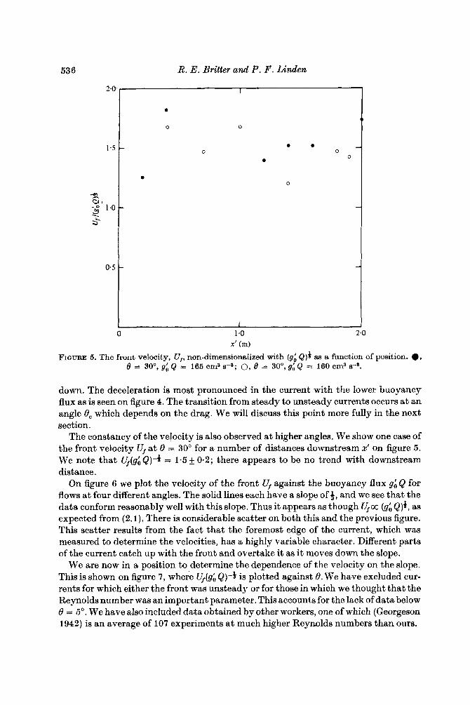
FIGURE 5. The front velocity, U,, non-dimensionalized with (96 Q$ as a function of position. q, 6 = 30°, g; Q = 165 em8 s - ~ ; 0, 8 = 30°, g; Q = 160 cm3 r9.
down. The deceleration is most pronounced in the current with the lower buoyancy flux as is seen on figure 4. The transition from steady to unsteady currents occurs at an angle 8, which depends on the drag. We will discuss this point more fully in the next section.
The constancy of the velocity is also observed a t higher angles. We show one case of the front velocity Ufat 8 = 30" for a number of distances downstream x' on figure 5 . We note that U,(gi &)a = 1.5 f 0.2; there appears to be no trend with downstream distance.
On figure 6 we plot the velocity of the front U, against the buoyancy flux gi Q for flows a t four different angles. The solid lines each have a slope of 9, and we see that the data conform reasonably well with this slope. Thus it appears as though V,cc (gh Q)*, as expected from (2. l ) , There is considerable scatter on both this and the previous figure. This scatter results from the fact that the foremost edge of the current, which was measured to determine the velocities, has a highly variable character. Different parts of the current catch up with the front and overtake it as it moves down the slope.
We are now in a position to determine the dependence of the velocity on the slope. This is shown on figure 7, where lJ,(gi &)-$ is plotted against 6. We have excluded cur- rents for which either the front was unsteady or for those in which we thought that the Reynolds number was an important parameter. This accounts for the lack of data below 8 = 5". We have also included data obtained by other workers, one of which (Georgeson 1942) is an average of 107 experiments a t much higher Reynolds numbers than ours.

Motion of a gravity current down an incline 537
t
1 10' 102 103
gb Q (cm3 s - ~ )
FIGURE 6. The front velocity as a function of the buoyancy flux g6 Q for 8 = 5' (o), 8 = 10' (.), 0, = 45' (0) and 0 = 90" (m). The lines have a slope of + &.
The remarkable feature of these results is the relatively small variation of front velocity with 0. This is because of the fact that although the gravitational force in- creases as the slope becomes more vertical there is also increased entrainment, both into the head'itself and into the flow behind. This produces an increased retarding force on the current as momentum is imparted to the entrained fluid.
The effect of entrainment is seen in the measurements in the growth of the height of the head with distance down the slope. These are shown on figure 8. Also shown on this figure is the growth of the following flow, dh/dx, taken from Ellison & Turner (1959). The aspect ratio of the head H / L increases with slope (figure 9) to about $ at 0 = go", corresponding to a near-cylindrical head.

538 R. E. Britter and P . F. Linden
I I I I I I I I
1 1 1 I I 1 I I I e
FIGURE 7. The non-dimensional front velocity, Uf/(g6 Q)#, plotted against the slope:*, George- son (1942); 0, Wood (1965); ., Tsang & Wood (1968); 0, Tochon-Dangay (1977); @, present study. The solid line is equation (4.4) with CD = 3 x 10⁻⁸ and the dashed line is with CD = 10 x 10-8.
4. Analysis The agreement between the experimental results and the dimensional analysis
presented in 5 2 indicates that the motion of the front of the current is determined by the properties of the (steady) following flow. We will show that it is possible to match the front onto the following flow and thereby determine the unknown functions fi, . . . , f4 which arise in the dimensional analysis (2.1)-(2.4).
The flow of an inclined plume, which is the flow immediately behind the head region, has been studied by Ellison & Turner (1959). They found that the mean velocity U is independent of the downstream distance 2, and that the width of the plume h increases linearly with x as a result of the entrainment of ambient fluid. Here the mean velocity U , width h and mean negative buoyancy of the plume are defined by
W
Uh = f udz, J o

Motion of a gravity current down an incline 539
0.4 1 I I 1 I I I I
0
0.3 -
0 10 20 30 40 SO 60 70 80 90
6 (ded FIGURE 8. The rate of growth of the head height, dH/dx, as a function of slope. Also shown is the range of observations of the growth of the depth of the following plume, dhldx, from Ellison & Turner (1959). W, Tsang & Wood (1968); 0 , present study.
and
where z is directed across the plume. As we have observed Ellison & Turner found that the rate of entrainment E
increased with increasing slope, and under the usual boundary-layer assumptions for a Boussinesq fluid showed that
dh S, Ri, tan 0 - C, ax l+gS,Ri, .
E E - =
Here C, is the drag coefficient due to stress at the lower boundary and
is a ‘normal’ Richardson number to which the flow rapidly adjusts. 8, and S, are profile constants defined by integrating across the plume (see equations (9) and (10) of Ellison & Turner): typically, 0.10 < S , < 0.15 and 0.6 < S, < 0.9.
As, typically, C, < 0.02 we see immediately from (4.1) that the behaviour of the inclined plume is independent of the wall stress a t large slopes. This is because the retarding force on the plume now comes primarily from the entrainment across the
~ i , = (g’hcose/u2),

540 0.6
R. E . Britter and P . F . Linden 1 I I I I I I I
I 1 I 1 1 I I I
10 20 30 40 50 60 70 80 90
6, (deg)
FIGURE 9. The aspect ratio of height to length of the head of a gravity currenl plotted &B a function of slope. 0, Wood (1965); m, Hopfinger & Tochon-Dangay (1977): 0 , present study.
outer edge. At small slopes, on the other hand, the two terms in the numerator of (4.1) become comparable in size and the bottom stress is no longer negligible.
Except at these very small slopes (< 0-5"), we have observed that the velocity of the front U, is steady and proportional to (gi Q)*. The same is true for the mean velocity of the following flow. This suggests that there is a relationship between U, and U , which we will determine by use of an argument similar to that proposed (incorrectly; seeTurner 1973, p. 73) by Prandtl(1952) for agravity current on a horizontal boundary. We consider a streamline near the lower boundary which, in a frame of reference moving with the head velocity, stagnates at the front. The velocity of fluid on this streamline in the following current is denoted by V,. If the energy loss along this streamline is equal to the change in potential energy due to the gravitational force along the streamline, then equality of the static pressures either side of the front a t the stagnation point leads to
p1 U; = p(U, - U,)2 + 2g(p -PI) Sz h cos 8. (44
u; = (v, - q ) 2 + 2g's2 h 8. (4.3)
In the Boussinesq limit p1 N p, and thus
Using the fact that &3, Ri, < 1, (4.1), (4.3) and conservation of buoyancy flux in the plume leads to the result that
(4.4) uf =++ asin8 ) ( sin8 )-+
In the derivation of (4.4) we have related U, to the mean velocity of the following flow by writing Us = aU. It seems likely that the streamline with the maximum velocity
(96 &Ia a 2(E+CD) E + C D

Motion of a gravity current down an incline 54 1
will be the one which stagnates at the front of the head, the others with smaller velo- cities being deflected backwards before reaching the foremost point. Assuming that this is the case, direct measurements of the mean and maximum velocity of the following flow by Ellison & Turner (1959) give a = 1.45-1.65 depending on the slope, whilst a Gaussian velocity profile gives a = J2. On the other hand, if U, is identified with the mean velocity a = 1. We shall compromise and take a = * ( 1 + J2) = 1.2. The front velocity given by (4.4) varies by 15 yo, which is within the scatter of our data, due to these uncertainties in the value of a.
Taking typical values of E = 10-38 and 8, = 0.75 from Ellison & Turner (1959), the front velocity predicted by (4.4) is shown in figure 7. Two curves are shown corres- ponding to different values of the drag coefficient C,. We see that at high slopes the effect of changing the drag coefficient is negligible as most of the retardation of the current is produced by entrainment. At small slopes, however, the effect of bottom drag is noticeable. The drag coefficient C, is probably a function of the precise stratifi- cation in the current (Ellison & Turner 1959), which is, in turn, determined by the entrainment rate E . Similarly, turbulence generated at the lower boundary produces entrainment into the current, and so there is an interdependence between E and C,. However, these effects are not likely to be important at large slopes, as some pre- liminary experiments for 8 2 30" have shown the entrainment is independent of the value of C,.
The assumption that the energy loss along the stagnating streamline is equal to the change in potential energy along the streamline cannot be justified rigorously. In the following flow the equality is met precisely, as there is no net acceleration down the slope. Therefore we are supposing that the mixing processes in the head are essen- tially the same as in the following flow. As, in both cases, the mixing takes place by shear instability, this does not seem an unreasonable first approximation.
Strictly speaking, it is also necessary to take account of the fact that the head is expanding as it moves down the slope. However, provided dH/dx < 1, the neglect of this effect is small. In our experiments dH/dx increases with slope and is N 0.35 for a vertical plume, so that treating the head as steady may lead to error a t the largest slopes.
The agreement between the theoretical result (4.4) and the experimental data is very satisfactory, provided 8 2 5". For slopes smaller than 5" additional effects must be considered. The first of these can be seen by considering (4.1) in the limit 8+ 0. Since E M 0, it is necessary that
for a steady flow to exist. In the absence of mixing, S, = 1 and U3/(gb Q ) N 2 (Simpson & Britter 1979) and (4.5) gives a critical angle 6, for a steady flow 8, N 2 c D . Typically C, N 3-0 x 10-3 for a large-Reynolds-number flow, and (4.5) implies that only for slopes greater than 0.34" is the buoyancy force down the slope large enough to counter- act the bottom friction and produce a steady flow. Our experimental results show that the current decelerates when 8 < 0.5", but is steady at larger slopes. We did not, however, investigate this transition between steady and time-dependent currents very thoroughly.
For slopes greater than 8, but small enough so that bottom friction is still important,

542 R. E . Britter and P. F . Linden
say 0.5" < 0 < 5", the current will be steady. As entrainment is small, (4.1) implies that
The drag coefficient C, is a function of the Reynolds number Re of the flow and so the second effect of the bottom friction a t small slopes is to introduce a dependence on Re. Of course, if Re is large enough, Reynolds-number dependence will be small, but in the present experiments we are unable to reach high enough values of Re a t these low slopes. Britter & Simpson (1978) estimate that it is necessary for Re to exceed lo3 before Reynolds number effects become unimportant and we do not achieve these values until B 2 5". Consequently, we have omitted the data taken for 8 < 5 O , on figure 7.
5. Discussion It has been shown experimentally that the head of a gravity current, produced by a
continuous source of buoyancy, has a constant velocity when flowing down a slope 0 2 0.5". On smaller slopes 0 5 0.5" the velocity of the head decreases with distance from the source, as the component of the buoyancy force down the slope is insufficient to overcome friction at the lower boundary.
Probably the most striking result of these experiments is that the head velocity 4, when non-dimensionalized by the cube root of the buoyancy flux (g; Q)*, is almost constant over the whole range of slopes from 5" < 0 < 90". This lack of variation results from the fact that the increased buoyancy force is counteracted by increased entrain- ment as 0 increases, leaving the velocity of the head virtually unaffected. We find that U,l(g; &)* = 1.5 f 0.2 for 5" < 8 < go", a result which is predicted by some simple analysis.
At large slopes, say 8 2 30°, we find from (4.2) that, in the Boussinesq limit, U, N BUS. If we write, as discussed in $4, Us = 1*2U, then this implies that the head travels a t a velocity @6U, where U is the mean velocityof the following flow. On the other hand, if the plume is very dense, p 3 pl , then, for 0-t go", Uf N Us, and so the front travels at about the same velocity as the mean velocity of the following flow. However, dilution of the plume will reduce p and the head will decelerate until the velocity approaches that of the Boussinesq plume.
A t small slopes, the inability to achieve a large Reynolds number in the present apparatus has prevented us from obtaining useful experimental data for 0 6 5". On the other hand we may consider the implications of our analysis for small slopes, say 0 -4 5") where E N 0 , S , 1: 1 and, if the Reynolds number is large, 01 = 1 . Using (4.1) and (4.3) it is possible to show that, in this limit,
This result, which emphasizes the importance of the slope angle at small slopes, is consistent with the experiments of Middleton (1966), who found that U,/U = 1 at very small angles and that V , / U decreased rapidly as 0 increased. We also recover from (5.1) the result that the motion is only steady if 8 2 2CD, as otherwise we obtain the physically unrealistic result that Uf > U .

Motion of a gravity current down a n incline 543
The motion within the head is somewhat akin to a thermal fed from behind by the following flow. The head grows in size as it travels along the slope due to both direct entrainment into the head itself and the addition of fluid from the current behind. The relative sizes of these can be calculated from the mean density p H ( x ) of the head. This quantity also has practical significance as it is related to the mean concentration of the constituent producing the density difference. If the cross-sectional area of the head is denoted by &nLH and
9;I = S(PH -PAIP1
then d g h 2 Qgh U - U f dL H dH -2 - dx = -&) (T +- d x ) (z) (z) x-2'
Note that, since U, a U cc (g; Q)b, dg&/dx has the functional form as (2.4) given by dimensional analysis.
The ratio of the flux of fluid into the head from the following flow to the total flux into the head is given by g;I(x)/g'(x), where g'(x) is the buoyancy excess in the follow- ing. flow. This ratio is
This ratio decreases as the slope increases, taking values 0.90, 0.63, 0.44 and 0.35 a t 0 = lo", 20", 45" and go", respectively. Thus at 10" direct edtrainrnent into the head accounts for about one-tenth of the growth of the head, whilst at 90" it provides about two-thirds of the total. For the axisymmetric starting plume (8 = go"), Turner (1962) found that the two contributions were approximately equal. This smaller amount of direct entrainment in the axisymmetric case is also reflected by the fact that dH/dx = 0.18 f 0.03, compared with dHldx = 0.35 for the two-dimensional starting plume.
R E F E R E N C E S
BRITTER, R. E. & SIMPSON, J. E. 1978 Experiments on the dynamics of a gravity current head. J . Fluid Mech. 88, 223-240.
ELLISON, T. H. & TURNER, J. S. 1959 Turbulent entrainment in stratified flows. J . Fluid Mech. 6, 423-448.
GEORGESON, E. H. M. 1942 The free streaming of gases in sloping galleries. Proc. Roy. Soc. A 180, 484-493.
HOPFINGER, E. J. & TOCHON-DANGAY, J. C. 1977 A model study of powder-snow avalanches. Glaciology 19 (81), 343-356.
MIDDLETON, G. V. 1966 Experiments on density and turbidity currents. 1. Motion of the head. Can. J . Eaah Sci. 3, 523-546.
PRANDTL, L. 1952 Essentials of Fluid Dynamics. Londbn: Blackie. SIMPSON, J. E. & BRITTER, R. E. 1979 The dynamics of the head of a gravity current advancing
TOCHON-DANGAY, J. C. 1977 Etude des courants de gravit6 sur forte pente avec application
TSANG, G. & WOOD, I. It. 1968 Motion of two-dimensional starting plume. J . Engng Mech.
TURNER, J. S . 1962 The 'starting plume' in neutral surroundings. J . Fluid Mech. 13, 356-368. TURNER, J. S. 1973 Buoyancy Esfects in Ftuids. Cambridge University Press. WOOD, I. R. 1965 Studies in unsteady self preserving turbulent flows. Univ. of N.8. W., Aust.,
over a horizontal surface. J . Fluid Mech. 94, 477-495.
aux avalanches poudreuses. ThBse, L'UniversitB Scientifique et MBdicale de Grenoble.
Div. A.S.C.E. EM6, 1547-1561.
Water Res. Lab. Rep. no. 81.

Journal of Fluid Mechanics, Vol. 99, part 3 Plate 1
FIGURE 2. For legend see overleaf.
BRITTER AND LINDEN (I”aci9ag p . 544)

Journal of Fluid Nechanics, Vol. 99, part 3 Plate 2
FIGURE 2. The head of a gravity current on slopes of O", 5", 20°, 45' and 90". The values of gi and (gh &) are approximately 100 cm 9-2 and 250 em3 s - ~ , respectively, for each run. The heads travel from right to left. The scale on the lower boundary is offset every 10 cm.
UKITTER . ~ N D LINDEN