Embed Size (px)
Citation preview
Mon. Not. R. Astron. Soc. 000, 1–7 (0000)
The myth of the molecular ring
C. L. Dobbs?1,2,3 and A. Burkert1,2†1 Max-Planck-Institut fur extraterrestrische Physik, Giessenbachstraße, D-85748 Garching, Germany2 Universitats-Sternwarte Munchen, Scheinerstraße 1, D-81679 Munchen, Germany3 School of Physics, University of Exeter, Stocker Road, Exeter EX4 4QL
18 May 2018
ABSTRACTWe investigate the structure of the Milky Way by determining how features in a spatialmap correspond to CO features in a velocity map. We examine structures includinglogarithmic spiral arms, a ring and a bar. We explore the available parameter space,including the pitch angle of the spiral arms, radius of a ring, and rotation curve. Weshow that surprisingly, a spiral arm provides a better fit to the observed molecular ringthan a true ring feature. This is because both a spiral arm, and the observed featureknown as the molecular ring, are curved in velocity longitude space. We find that muchof the CO emission in the velocity longitude map can be fitted by a nearly symmetric2 armed spiral pattern. One of the arms corresponds to the molecular ring, whilst theopposite arm naturally reproduces the Perseus arm. Multiple arms also contribute tofurther emission in the vicinity of the molecular ring and match other observed spiralarms. Whether the Galactic structure consists primarily of two, or several spiral arms,the presence of 2 symmetric logarithmic spirals, which begin in the vicinity of the endsof the bar, suggest a spiral density wave associated with the bar.
1 INTRODUCTION
Despite decades of observations, determining the spiralstructure of our Galaxy is still intrinsically difficult. It is noteven clear whether the Galaxy contains 2, 3 or 4 primaryspiral arms (Vallee 2005, 2008; Benjamin 2008; Steiman-Cameron et al. 2010), and whether the spiral structure is dif-ferent in the gas and the stars. Traditionally, much of the COemission of the Galaxy has been associated with a featureknown as the ‘molecular ring’ (Stecker et al. 1975; Cohen& Thaddeus 1977; Roman-Duval et al. 2010), around 4 kpcfrom the Galactic Centre. However it is unclear whether thisis truly a ring, or simply emission from nearby spiral arms,as suggested by simulations of spiral galaxies (Englmaier &Gerhard 1999; Rodriguez-Fernandez & Combes 2008; Babaet al. 2010).
In the past, the spiral structure for the Galaxy has pre-dominantly been determined from the stellar distribution(Vallee 2005 and references therein). Measuring distances tostars is difficult for distances larger than a few kpc how-ever due to extinction. Alternatively we can use a gas tracersuch as CO or Hi. In other galaxies, e.g. M83, M51, the spiralarms also tend to be much narrower in the gas than the stars,indicating that gas is likely a better tracer of spiral structure.For a spiral density wave, the gaseous and stellar spiral armsare expected to occupy slightly different patterns, with thegaseous arms slightly offset from the stellar arms except atcorotation, and with a smaller pitch angle (Gittins & Clarke2004) 1. The gaseous structure is also much more complex
1 although recent simulations of M51 (Dobbs et al. 2010) find
than the stellar, with interarm spurs, and branches betweenspiral arms absent in the stellar distribution.
CO and Hi maps of the Galaxy (e.g. Dame et al. 2001)clearly show the Perseus and Outer arms. However thereare also difficulties with using gas tracers: i) it is difficultto map the opposite side of the Galaxy, ii) the emission inthe inner part of the Galaxy is dominated by a broad bandin velocity-longitude (hereafter l − v) space, and iii) ambi-guities in calculating the distance to gaseous features fromthe rotation curve and velocity crowding. Thus mapping thespatial structure from the gas is far from straightforward.
In this paper we take a slightly different approach.Rather than using the molecular emission, or stellar distri-bution, to estimate the spiral structure, we instead assumethe gaseous spiral arms exhibit some pattern and see howwell they fit the observed CO emission. We do not performnumerical simulations rather we simply assume the gaseousspiral arms follow a logarithmic spiral pattern, assumed toarise from the gas response to a density wave. This has thecaveat that our results neglect streaming motions. Howeverif we can fit the spiral pattern even in the absence of stream-ing motions, this is a strong indication that the spiral pat-tern for our Galaxy can be represented by a simple m = 2 orm = 4 pattern. There are also two direct advantages of ourmethod; the first that we can readily explore a large param-eter space, and the second that we do not need to includethe pattern speed, or spiral potential strength, which areunknown parameters. A similar approach has been carried
that for a kinematic wave driven by a tidal interaction, the stellar
and gaseous arms are not systematically offset.
c© 0000 RAS
arX
iv:1
201.
1775
v1 [
astr
o-ph
.GA
] 9
Jan
201
2
2 C. L. Dobbs
out by Russeil (2003) for star forming complexes, but thedistribution they use does not display strong spiral struc-ture. Steiman-Cameron et al. (2010) also fit spiral patternsto the intensity of FIR cooling lines at each position in theGalaxy.
2 METHOD
To obtain spiral arms, we assume that the molecular gas liesin a 2 or 4 armed logarithmic spiral pattern. From standarddensity wave theory, the general expression for a logarithmicspiral pattern is
φ = A(r) cos
(n
tan ilog(r/r0) − (θ − Ωpt)
)(1)
where A(r) provides the amplitude of the spiral, n is thenumber of spiral arms, i is the pitch angle, r0 is a constantwhich controls the orientation of the arms, and Ωp the pat-tern speed. Since we only require the pattern at the presenttime, we can set t = 0. To find the minima of the potential,we then simply have
n
tan ilog(r/r0) = θ, (2)
and given some values of i and r0 we can map the positionsof the spiral arms.
We then compute the velocity longitude map, requiringa given rotation curve. We adopt a flat rotation curve fora logarithmic potential (Binney & Tremaine 1987), of theform
v = v0r2/(R2
c + r2) (3)
where v0 and Rc are constants. Rc determines how far fromthe centre of the Galaxy the rotation curve becomes flat.Past observations have indicated the rotation of the Galaxyis between 210 and 240 km s−1 over the majority of theGalaxy (Clemens 1985). The standard reference is Θ0 = 220km s−1 at R0=8 kpc. However more recent measurements ofthe distance to masers suggest that Θ0 may be 250 km s−1
or higher (Reid et al. 2009). We tried both v0 =220 and250 km s−1, though we only show results for v0=250 km s−1.As the observations show that the velocity curve is still veryhigh close to the centre of the Galaxy, we choose Rc = 0.1kpc. Then we place the observer a distance of 8 kpc fromthe centre of the Galaxy.
We show results where we adopt a spiral arm pattern,and where we assume that the molecular ring is truly due toa ring. Given that we simply use the computed locations ofthe spiral arms, or ring, we can investigate a large parame-ter space. The free parameters in our models are the pitchangle of the spiral arms; the radius of a ring feature; the ori-entation of the spiral arms, the length and orientation of thebar; the Galocentric radius and the rotation velocity v0. Wemainly consider the orientation and pitch angle of the spi-ral arms, but we also briefly mention the other parameters.In principle, this analysis could be carried out without anyprior knowledge of the structure of the Milky Way, but giventhe large parameter space we have started with the locationof the observer, the rotation curve, and the orientation ofthe bar roughly based on observations.
2.1 Fitting technique
We can compare how well our models match the CO ob-servations by matching features such as the molecular ring,Perseus Arm, Outer Arm simply by eye. However we alsocarry out a χ2 fitting between the velocity longitude mapof Dame et al. (2001) and our models. The difficulty of thelatter is that we have to make numerous assumptions to con-vert our models into emission maps. We assume the emissionfollows a Gaussian centred on the proposed spiral arms witha velocity dispersion of 7 km s−1. We also have to make someassumptions about how the emission scales with radius. Wesuppose the intensity falls with 1/r2LSR where rLSR is thedistance to the local standard of rest (located at R = 8 kpc).We also assume that the amount of molecular gas falls offas 1/rGAL where rGAL is the radius of the Galaxy. We thennormalise the emission so that the total emission matchesthat of Dame et al. (2001). We calculate the difference be-tween the observed and model emission, σ2 = (Iobs−Imod)2,and minimise over the spiral arm orientation or molecularring radius. Whilst departures from these assumptions (e.g.a different velocity dispersion, changes in scaling with rLSR
and rGAL) change σ, how well the models fit relative to eachother does not change.
There are still some difficulties with our fitting processwhen we compare to spiral features. In the Galaxy, localemission is present at all longitudes, but absent in our mod-els. Away from the Galactic Centre, this emission dominatesover features such as the Outer Arm. Thus we cannot reallytest for these features without introducing some arbitraryweighting, so we instead restrict our fit to longitudes be-tween 50 and -50. We still found however that this methodwas biased towards lower pitch angles, simply because thearms cross the region l = ±50 multiple times. Thereforewe also carried out a fit just to the part of the main spiralarm which coincides with the molecular ring. We refer tothe two fits as ‘total’ (i.e. for all the parts of the arms inour models between l =50 and -50) and ‘arm’ (i.e. justbetween the tangent points of the arm which coincides withthe molecular ring).
In the first part of the results we compare a 2 armed and4 armed spiral pattern, so we use the ‘total’ fit. In Section3.1 we vary the pitch angle and compare results with boththe ‘total’ and ‘arm’ fits. The best fit orientation of the armdoes not depend on which technique is used, but the pitchangle does.
3 RESULTS
In Figure 1 we show our best fit to the molecular ring for a2 armed spiral pattern (top panel) adopting a pitch angle of11 (see next section for results with different pitch angles).This model includes a bar of radius 3 kpc, which we havesimply placed across the Galactic centre 45 clockwise fromthe position of the Sun. In all figures, we simply show thelines tracing peak emission along the arms, rather than oursynthetic emission maps. The lines are overplotted on thevelocity longitude map of Rodriguez-Fernandez & Combes(2008), which used the data of Dame et al. (2001).
From Figure 1, top panel, we see that the Scutum-Centaurus (hereafter Sct-Cen) arm provides a good fit to
c© 0000 RAS, MNRAS 000, 1–7
The myth of the molecular ring 3
-300
-200
-100
0
100
200
300
-80-60-40-20 0 20 40 60 80
y (kp
c)
x (kpc)
-300
-200
-100
0
100
200
300
-80-60-40-20 0 20 40 60 80
y (kp
c)
x (kpc)
-10
-5
0
5
10
-10 -5 0 5 10
y (k
pc)
x (kpc)
4kpc5 kpc6 kpc
-300
-200
-100
0
100
200
300
-80-60-40-20 0 20 40 60 80
y (kp
c)
x (kpc)
4kpc5 kpc6 kpc
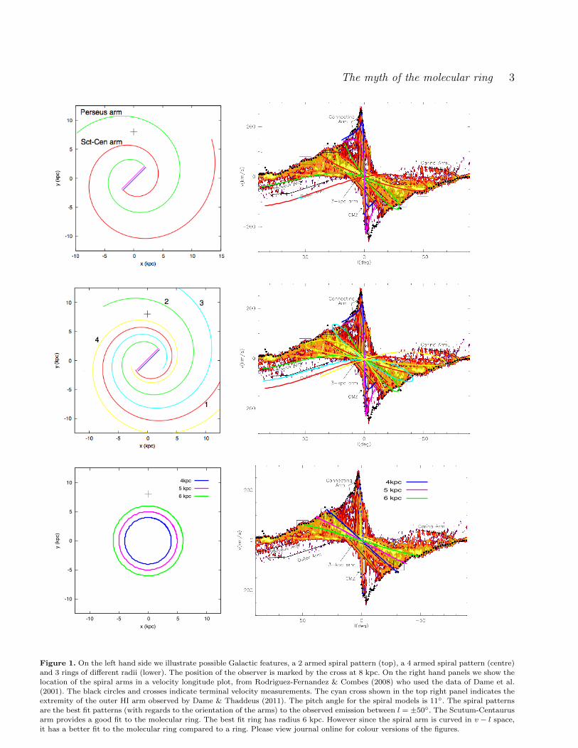
Figure 1. On the left hand side we illustrate possible Galactic features, a 2 armed spiral pattern (top), a 4 armed spiral pattern (centre)
and 3 rings of different radii (lower). The position of the observer is marked by the cross at 8 kpc. On the right hand panels we show the
location of the spiral arms in a velocity longitude plot, from Rodriguez-Fernandez & Combes (2008) who used the data of Dame et al.(2001). The black circles and crosses indicate terminal velocity measurements. The cyan cross shown in the top right panel indicates the
extremity of the outer HI arm observed by Dame & Thaddeus (2011). The pitch angle for the spiral models is 11. The spiral patternsare the best fit patterns (with regards to the orientation of the arms) to the observed emission between l = ±50. The Scutum-Centaurus
arm provides a good fit to the molecular ring. The best fit ring has radius 6 kpc. However since the spiral arm is curved in v − l space,
it has a better fit to the molecular ring compared to a ring. Please view journal online for colour versions of the figures.
c© 0000 RAS, MNRAS 000, 1–7
4 C. L. Dobbs
the molecular ring. The part of this arm in the lower leftquadrant (negative l and v) also agrees very well with thelocation of the new arm as measured in HI by Dame &Thaddeus (2011). As also noted in their paper, it is verydifficult to get the Sct-Cen arm to continue to the Outerarm, without providing a very asymmetric spiral pattern.The second spiral arm provides a good fit to the Perseusarm. The best fit for the second arm was almost symmetricwith the Sct-Cen arm, only asymmetric by 10. It is possi-ble to rotate the arms slightly and produce better matchesto the tangent points (boxes), still matching the spiral armsreasonably well, but here we simply show the best results toour molecular ring fitting technique. The emission from thesecond spiral arm (green) extends a little outside the scopeof the observed CO emission. With a lower rotation curve(v = 220 km s−1), this is avoided. Otherwise there is littledifference for a lower rotation curve.
It is difficult to constrain the starting radius of the Sct-Cen Arm, given the complex emission towards the GalacticCentre. We can however see that the arm marked as thePerseus arm cannot extend much further inward, else therewould be unobserved emission (at l ∼ 15, v ∼ 150 km s−1)for this model.
In the centre panels of Figure 1 we show a 4 armed spi-ral model. To the two armed model, we added a third arm(cyan) using our fitting technique. This arm naturally repro-duces the Outer arm emission. We tried adding a 4th arm,however our fitting technique did not show any minimumin the expected vicinity. Since this arm is close to the Sun(or observer), the emission, and therefore results becamedominated by this arm, whereas for the observations, thestrongest emission coincides with the molecular ring. There-fore we reduced our calculated emission from this arm bya factor of 10 compared to the other arms to fit the fourtharm. This arm then reproduces the Carina arm, and also thetangent point at l ∼ 50, v ∼ 50 km s−1. The factor of 10 issomewhat arbitrary but does seem to indicate that any armbetween the Sun and the Sct-Cen arm is somewhat weaker.Overall though, the addition of extra arms superimposed onthe Sct-Cen arm contribute further to the emission of themolecular ring.
In the lower panels of Figure 1 we show the results forrings. We show 3 examples with radii of 4, 5 and 6 kpc.It can be seen from Figure 1 that a ring does not coveras much of the emission of the observed ‘molecular ring’ asa spiral arm. The reason for this is because the observedmolecular ring is actually curved in v − l space, whereasthe emission from an actual ring is a straight line. So wesee that whilst a 4 or 5 kpc radius ring can fit emissionfor positive longitudes, it misses the emission at negativelongitudes. Conversely, a 6 kpc ring reproduces the observedemission at negative longitudes, but does not agree with thebrightest observed emission at positive longitudes. From ourfitting technique, the 6 kpc ring gave the best fit, althoughby eye 5 kpc appears best (the difference is probably becausethe observed emission extends further at negative longitudescompared to positive longitudes).
In Table 1 we show the difference between the modelestimated CO emission and that of the observations, σ2 =(Im − Iobs)2 for 1 (corresponding to the Sct-Cen arm inFigure 1), 2 (upper panels, Figure 1) and 4 (middle pan-els, Figure 1) armed spiral models with a pitch angle of 11
Model σ2/σ24arm
Ring 2.271 armed spiral 2.02
2 armed spiral 1.334 armed spiral 1.0
Table 1. The difference between the observed and analytic emis-sion, σ2, where σ2 = (Im − Iobs)2 is shown for the ring model,
and spiral arm models with a pitch angle of 11. The 1 armed
model refers to just the Sct-Cen arm in Figure 1. The resultsare normalised to our best fit model, the 4 armed spiral. The 4
armed spiral provides the best fit, though all cases are a better
fit compared to a ring.
Pitch angle () σ2/σ24arm (‘total’) σ2/σ2
4arm (‘arm’)
8.5 2.00 2.1311 2.02 2.08
13.5 2.11 2.06
16 2.18 2.01
Table 2. We show the difference between the observed and ana-
lytic emission, σ2, where σ2 = (Im − Iobs)2 for the Sct-Cen armwith different pitch angles. For the left column, we consider emis-
sion along the total length of the arm. For the right column, we
consider emission only between the tangent points of the Sct-Cenarm. The results are normalised as for Table 1. The best fit pitch
angle is dependent on the fitting technique, however in all cases,the fit is better compared to a ring (Table 1).
and a ring of 6 kpc radius. The spiral models provide betterfits statistically compared to the ring model. The 2 and 4armed spirals are also better fits compared to the 1 armedmodel or ring, which is not surprising because they allowmore complexity and cover a larger area where the observedemission lies. However distinguishing between the 2 and 4armed models (and allowing for the different degrees of free-dom) is probably beyond the scope of our approach.
We also performed a simpler test to compare betweenour models and the observed CO emission only between thetangent points of the Sct-Cen arm (the ‘arm’ fit). This testcorrects for any bias due to spiral arms crossing the regionl = ±50 multiple times. We show the results in Table 2, andagain the spiral arm models still provide better fits comparedto the ring.
3.1 Parameter study
In this section, we investigate how altering the parameters ofour models affects how well the spiral arms fit the observedemission.
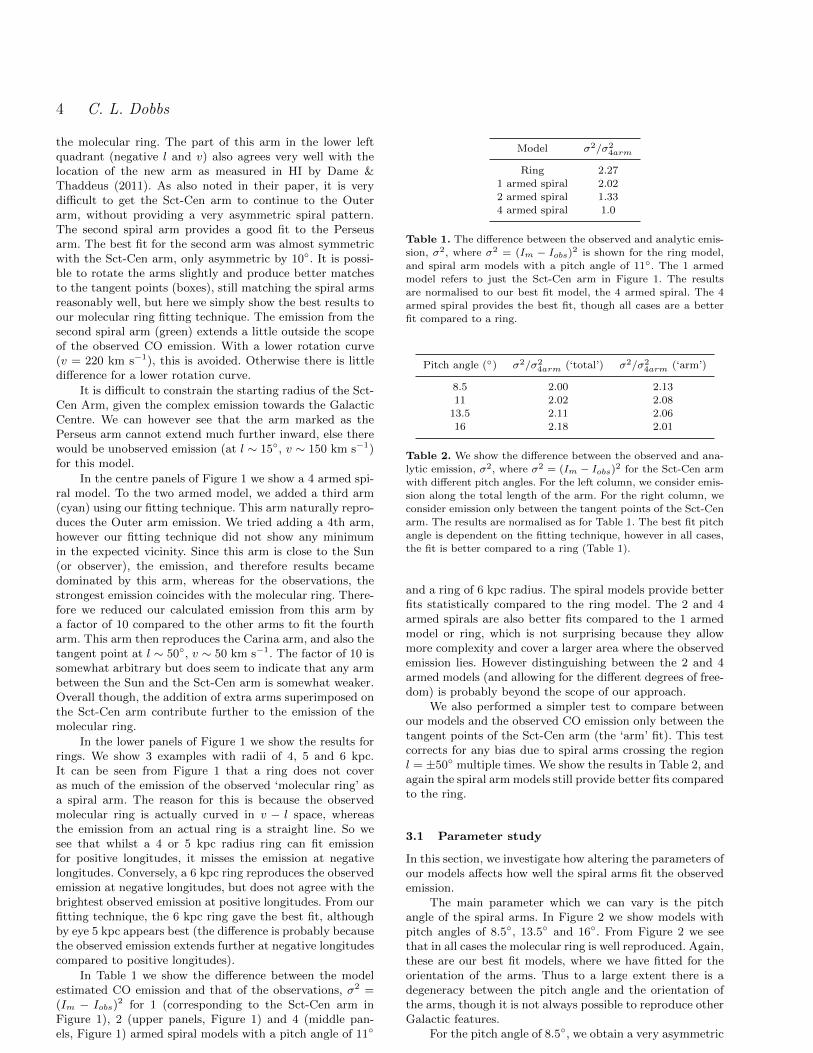
The main parameter which we can vary is the pitchangle of the spiral arms. In Figure 2 we show models withpitch angles of 8.5, 13.5 and 16. From Figure 2 we seethat in all cases the molecular ring is well reproduced. Again,these are our best fit models, where we have fitted for theorientation of the arms. Thus to a large extent there is adegeneracy between the pitch angle and the orientation ofthe arms, though it is not always possible to reproduce otherGalactic features.
For the pitch angle of 8.5, we obtain a very asymmetric
c© 0000 RAS, MNRAS 000, 1–7

The myth of the molecular ring 5
-300
-200
-100
0
100
200
300
-80-60-40-20 0 20 40 60 80
y (kp
c)
x (kpc)
-300
-200
-100
0
100
200
300
-80-60-40-20 0 20 40 60 80
y (kp
c)
x (kpc)
-300
-200
-100
0
100
200
300
-80-60-40-20 0 20 40 60 80
y (kp
c)
x (kpc)
Figure 2. The spiral pattern is shown for models with 2 spiral arms and pitch angles of 8.5 (top), 13.5 (centre) and 16 (lower). Theposition of the observer is marked by the cross at 8 kpc. The arms have been rotated to provide a best fit to the data. In all cases theSct-Cen arm easily fits the molecular ring. For a pitch angle of 8.5, there is a good agreement with the observed CO emission, but
the spiral arms are highly asymmetric. For higher pitch angles, we do not reproduce the tangent point at l = 30, v = −100 km s−1
as the arms do not extend to the inner part of the Galaxy, and also it is difficult to reproduce this tangent point and the Perseus armsimultaneously. Please view journal online for colour versions of the figures.
c© 0000 RAS, MNRAS 000, 1–7
6 C. L. Dobbs
pattern. Our fitting technique does not take into accounttangent points, or the Perseus arm which are also constraintson the second spiral arm (green). However even if we adjustthe second spiral to fit the tangent point at l ∼ −30, v ∼−100 km s−1, the structure is still highly asymmetric.
For pitch angles of 13.5 and 16 we do not producethe tangent point at l ∼ −30, v ∼ −100 km s−1 simplybecause the emission does not extend that far inwards. Wecould continue the arms for another half rotation, howeverthis would lead to a rather short (. 2 kpc) bar, with theassumption that the arms begin at the bar. In any caseit is difficult to match the tangent point and the Perseusarm simultaneously, especially when the pitch angle is 16.Another constraint is the observed distance to the Perseusarm, which is around 2 kpc towards l = 134 (Xu et al.2006). We get good agreement with this for the models wepresent. However if we constrain the Perseus spiral arm tomatch the the tangent point at l ∼ −30, v ∼ −100 km s−1,the distance to the Perseus arm becomes too large for thehigher pitch angles. Finally we note that we do not get goodagreement with the newly observed outer HI arm (Dame &Thaddeus 2011) with these pitch angles, in particular 8.5
and 16.We show in Table 2 how well the models with differ-
ent pitch angles fit the observed data, using the ‘total’ and‘arm’ fits. The ‘total’ fit favours lower pitch angles, becausethe arms cover more of the region of observed emission. The‘arm’ fit favours larger pitch angles, and provides a bestfit pitch angle of 16.5. Both techniques however neglectfeatures such as the Perseus arm, outer HI arm, and sup-posed tangent points, which appear necessary to constrainthe pitch angle. With these extra constraints, the 11 pitchangle reproduces more of the CO features.
We also tested the orientation of the bar, the rotationcurve and the position of the observer in the Galaxy. Asnoted before, decreasing the rotation curve to 220 km s−1
slightly reduces the scope of the emission in velocity space.Moving the radius of the observer closer to the GalacticCentre increases the span of the nearer spiral arm in thevelocity plot. Thus to still achieve a similar pattern to Fig-ure 1, a lower pitch angle would be required, and likewiseif the observer is further out in the Galaxy, a higher pitchangle would be needed. So again there is a degeneracy be-tween the Galocentric radius and the pitch angle, but again,with significant departures from the observed values, it ismore difficult to reproduce all the features in the CO mapsimultaneously.
Changing the orientation of the bar does not make avery noticeable difference to the location of emission associ-ated with the bar. It is difficult to reproduce the full extentof CO emission in velocity space associated with the bar, i.e.for velocities in excess of +200 km s−1. This could be dueto a higher rotation curve, motions along the bar, or simplyfeatures near the Galactic Centre that we are missing.
3.2 Comparison to other models of the Milky Way
There have been several models suggested for the structureof the Milky Way in recent years. Vallee (2005) proposes a 4armed spiral model with a pitch angle of 12. The main dif-ference between his model, and our 4-armed model is thatwe suppose that the Perseus and Scutum-Centaurus Arm
start at the bar, whereas Vallee (2005) assumes that theSagittarius-Carina and Cygnus (Outer) Arms start at thebar (these are the equivalent to the arms coloured cyan andyellow on Figure 1). We constrained the models such thatthe Scutum-Centaurus and Perseus Arm begin at the bar,because these arms are seen in the stars and the gas, whereasthe other arms may not be associated with stellar enhance-ments (Drimmel 2000; Benjamin 2008).
Churchwell et al. (2009) also proposed a schematic ofthe Galaxy based on the GLIMPSE infrared survey (seealso Benjamin 2008). They propose that the Galaxy is a2-armed spiral, the main arms being the Scutum-Centaurusand Perseus Arms, with several secondary spiral arms. Theyadopt a long bar, but do not state the pitch angle of thearms. This is similar to our 11 pitch angle model if wechoose a longer bar, and neglect the first 180 rotation ofthe spiral arms, or the models we show for larger pitch an-gles. We did note though in Section 3.1 that starting thearms further out in the disc would likely miss regions ofemission in the CO l − v diagram.
Finally, Steiman-Cameron et al. (2010) propose a modelbased on [CII] and [NII] cooling lines. This is very similarto our 4 armed model in Figure 1. The main difference isthat they use slightly larger pitch angles (13 − 16), andwhilst we obtained a reasonable fit with one pitch angle,they used different pitch angles for each arm. With the pitchangle for the Scutum-Centaurus arm they used (15.5), itis difficult to reproduce the HI feature seen by Dame &Thaddeus (2011) as the arm barely extends to the thirdGalactic quadrant.
4 DISCUSSION
It is relatively easy to find a spiral arm configuration suchthat the region corresponding to the molecular ring is re-produced by a nearby spiral arm. If we rotated the nearestspiral arm (with respect to the Galactic Centre), we wouldobtain a similar feature with a different gradient. Increasingor decreasing the pitch angle of the arms changes the extentof the molecular ring. Other spiral arms enhance the molec-ular ring, as all overlap at least at l = 0. Finally, as themolecular gas surface density decreases with radius, outsidethe vicinity of the bar, the maximum emission will be fromthe near spiral arm close to the bar.
Whilst a ring feature can also represent CO emissionsimilar to the observed molecular ring, a ring does not fitthe observations as well as a spiral arm. This is because thespiral arm appears curved in v − l space, similar to the ob-served molecular ring, but dissimilar to a true ring. Thuswhilst we cannot rule out that the molecular ring corre-sponds to a true ring, we found that a spiral arm produceda better fit compared to a ring over all our range of pitch an-gles, and this finding was robust to the details of our fittingtechnique.
Binney et al. (1991) proposed that the molecular ringcould be due to the outer Lindblad resonance of the bar. Wealso performed simulations with a barred potential to exam-ine whether a gaseous ring would form. However generallygas features produced at the end of the bar are highly ellip-tical, as seen already in numerical simulations (e.g. Wada &Norman (2001); Lin et al. (2008)). The elongated features
c© 0000 RAS, MNRAS 000, 1–7
The myth of the molecular ring 7
due to the bar in our Galaxy may well correspond to the farand near 3 kpc arms, seen in the molecular gas data. In oursimulations of bars, any feature corresponding to a ring wasagain simply the spiral arms close to the Galactic centre. Infact, few galaxies show obvious rings in the gas at the end ofthe bar – typically rings are nuclear rings much nearer to thecentre, or features caused by large collisions. Our Galaxy isprobably not unusual in this respect.
Our fiducial model adopts a pitch angle of 11, assuminga Galocentric distance of 8 kpc. All the pitch angles we triedcould reproduce a feature similar to the molecular ring, andfrom fitting the molecular ring alone we find a best fit pitchangle of 16.5. However deviations from the 11 model tendto reproduce fewer of the other observed features in the COl − v diagram, or produce highly asymmetric arms. Largerpitch angles seem to point towards a longer bar, which meansCO in the lower right quadrant of the v − l plot is absent.Moreover the supposed tangent point of the inner part ofthe Perseus arm, and the distance to the Perseus arm, can-not be matched simultaneously with large pitch angles. Our2 armed spiral model is fairly symmetric, and is thus consis-tent with a density wave originating at the bar. Though wecannot rule out that the Galaxy simply consists of several,asymmetric, spiral arms, it seems less likely that by coinci-dence they match both the inner and outer spiral structuresimultaneously. Reproducing all the features in the CO, e.g.Outer Arm, Carina Arm, requires 4 spiral arms.
It is thought that the Galaxy may exhibit two spiralarms which are evident in both stars and gas, whilst otherfeatures, e.g. the Sagittarius Arm, are only seen in the gas(Drimmel 2000; Benjamin 2008). The next step would beto try and produce hydrodynamical models with potentialsbased on the 2 armed spiral pattern shown here for exam-ple, and see whether there are gaseous spurs or arms whichdo not correspond to stellar features and whether they cor-respond to observed features in CO. Such features couldarise from the shearing of clouds in the spiral arms (Kim& Ostriker 2002; Dobbs & Bonnell 2006) or resonances inthe disc (Patsis et al. 1997; Chakrabarti et al. 2003; Martoset al. 2004).
5 ACKNOWLEDGMENTS
We thank the referee Tyler Foster for suggestions that havesubstantially improved the paper. We are very grateful toNemesio Rodriguez for providing the CO velocity longitudeplot from Rodriguez-Fernandez & Combes (2008), and toTom Dame for providing the CO velocity-longitude dataused for our comparison tests. We also thank Panos Pat-sis for valuable discussions. CLD acknowledges funding fromthe European Research Council for the FP7 ERC startinggrant project LOCALSTAR.
REFERENCES
Baba J., Saitoh T. R., Wada K., 2010, PASJ, 62, 1413Benjamin R. A., 2008, in H. Beuther, H. Linz, & T. Hen-ning ed., Massive Star Formation: Observations ConfrontTheory Vol. 387 of Astronomical Society of the Pacific
Conference Series, The Spiral Structure of the Galaxy:Something Old, Something New.... pp 375–+
Binney J., Gerhard O. E., Stark A. A., Bally J., UchidaK. I., 1991, MNRAS, 252, 210
Binney J., Tremaine S., 1987, Galactic dynamics. Prince-ton, NJ, Princeton University Press, 1987, 747 p.
Chakrabarti S., Laughlin G., Shu F. H., 2003, ApJ, 596,220
Churchwell E., Babler B. L., Meade M. R., Whitney B. A.,Benjamin R., Indebetouw R., Cyganowski C., RobitailleT. P., Povich M., Watson C., Bracker S., 2009, PASP, 121,213
Clemens D. P., 1985, ApJ, 295, 422Cohen R. S., Thaddeus P., 1977, ApJL, 217, L155Dame T. M., Hartmann D., Thaddeus P., 2001, ApJ, 547,792
Dame T. M., Thaddeus P., 2011, ApJL, 734, L24+Dobbs C. L., Bonnell I. A., 2006, MNRAS, 367, 873Dobbs C. L., Theis C., Pringle J. E., Bate M. R., 2010,MNRAS, 403, 625
Drimmel R., 2000, A&A, 358, L13Englmaier P., Gerhard O., 1999, MNRAS, 304, 512Gittins D. M., Clarke C. J., 2004, MNRAS, 349, 909Kim W., Ostriker E. C., 2002, ApJ, 570, 132Lin L.-H., Yuan C., Buta R., 2008, ApJ, 684, 1048Martos M., Hernandez X., Yanez M., Moreno E., PichardoB., 2004, MNRAS, 350, L47
Patsis P. A., Grosbol P., Hiotelis N., 1997, A&A, 323, 762Reid M. J., Menten K. M., Zheng X. W., Brunthaler A.,Moscadelli L., Xu Y., Zhang B., Sato M., Honma M., Hi-rota T., Hachisuka K., Choi Y. K., Moellenbrock G. A.,Bartkiewicz A., 2009, ApJ, 700, 137
Rodriguez-Fernandez N. J., Combes F., 2008, A&A, 489,115
Roman-Duval J., Jackson J. M., Heyer M., Rathborne J.,Simon R., 2010, ApJ, 723, 492
Russeil D., 2003, A&A, 397, 133Stecker F. W., Solomon P. M., Scoville N. Z., Ryter C. E.,1975, ApJ, 201, 90
Steiman-Cameron T. Y., Wolfire M., Hollenbach D., 2010,ApJ, 722, 1460
Vallee J. P., 2005, AJ, 130, 569Vallee J. P., 2008, ApJ, 681, 303Wada K., Norman C. A., 2001, ApJ, 547, 172Xu Y., Reid M. J., Zheng X. W., Menten K. M., 2006,Science, 311, 54
This paper has been typeset from a TEX/ LATEX file preparedby the author.
c© 0000 RAS, MNRAS 000, 1–7