Embed Size (px)
Citation preview

The 100 Series Drawout Relay range briefly comprises:
MR - IE: 3- Phase Multi Stage Overcurrent and Earth Fault Protection
MR - I: 3- Phase Multi Stage Overcurrent Protection
MR - EF: Single Phase Multi Stage Earth Fault Protection
MR - REF: Restricted Earth Fault Protection
MR - EX: Sensitive Earth Fault Protection
MR - CS: 3- Phase Voltage Check Synchronism
MR - VT: 3- Phase Multi Stage Over and Under Voltage Protection
MPR3E5: 3- Phase Motor Overload & Earth Fault Protection
100 Series Drawout Relays the new competitive range of withdrawable protection relays
Page 1
Time & Date Stamping to 1ms
32 Event Trip and Alarm Histories
Last Fault with Trip Data
Stats Information
Fully Programmable Settings
Programmable Digital Inputs
Programmable Relay Outputs
Developed from many years experience of intelligent protection and control applications within the high specification offshore / onshore Oil and Gas and Petrochemical sectors.
P&B Engineering’s new highly sophisticated relay range has been designed to offer cost effective, versatile and competitive protection relays for medium voltage switchgear.
Integral to the design is the flexible twin board relay hardware platform and robust construction. This allows for consistency in relay manufac-ture and functional flexibility within firmware.
The rationalised hardware and pin arrangement provides the following:
4x Output Relays with Changeover Contacts 2x Digital Inputs 4x Push Buttons for Navigable Menu Driven LCD Screen 2x Tri Colour LEDs for Indication and Status 1x Front Mounted RS232 Port 1x Rear Mounted RS485 Port for Modbus RTU or P&B Protocol 4x 1A or 5A CT Inputs or 4x VT Inputs (or combination of, function dependant) Wide Ranging Auxiliary AC/DC Power Supply
The MR-IE protection relay
shown slightly withdrawn from the relay case &with the hinged perspex front cover removed

100 Series Drawout Relays the new competitive range of withdrawable protection relays
Page 2
LCD Display
The navigable LCD menu is driven by the four push buttons, this allows access to measured and recorded data as well as providing a programming interface for the relay settings.The menu is structured in an intuitive way to allow easy of use and understanding of the presented information. Where possible acronyms are not used, instead full text descriptions are displayed.
The front RS232 port can be used for local programming or data extraction as well as firmware updates.
The rear port is normally used for connection to a daisy-chained, twisted pair data highway which in turn is connected to SCADA or DCS systems or to a local electrical work station (EWS). This provides a route for direct remote circuit monitoring, telemetery or metering and consumption analysis.
In addition the Xcell Data Concentrator can be used as a protocol or host interface hub and allows many multiples of relays to be connected together. The Xcell is a fault tolerant and fully dual redundant system for relay communication.
For over 60 years, we have invested significantly in product design in or-der to produce equipment capable of operating in demanding and high ambient conditions.This thermal image shows the PSU / Relay pcb performing under high am-bient endurance testing during IEC and UL type testing.
Environmental / Technical Data
Rated Inputs: Withstand: CT In = 1A or 5A CT Cont 4x VT Vn= 110 - 415Vac 50-60Hz 10s 30x Aux. Supply 80-265Vac, 90 -300Vdc 1s 100x Half Wave 250xBurden / Consumption: VT 1Kv CTs <0.01VA Relays 10A @ 240Vac VTs <0.01VA Temp Up to 60degree C cont. Aux. Supply Approx. 10W Min Op Time: 30msElectrical: Trip Time Acc: +/- 20ms IEC61000-4 Display Acc: +/- 3% IEC60255-21 Measurement: True RMS IEC60255-22 Weight (app): 1Kg
Examples of the LCD screen layout
Disturbance Recording
Each relay can be equipped with its own onboard disturbance recording facility. This provides up to 8 seconds of waveform capture and can be multi triggered and weighted pre and post fault. Each phase is individually recorded and can be extracted from the relay using the front RS232 port in a ‘comtrade’ format for analysis by any compatible software.
A Smart Card facility can be included within the relay to further aid programming or be used to collect statistical and re-corded data. Settings are stored to a card and those settings can then be down-loaded to relays of the same type and function. The top handle of the relay is replaced by a credit card sized slot to allow smart card access.
Vision Control, P&Bs pc based programming tool can be used to program and configure multiple relays through either communication port.
Settings can then be saved, stored & printed.
100 Series Drawout Relays the new competitive range of withdrawable protection relays
Page 3
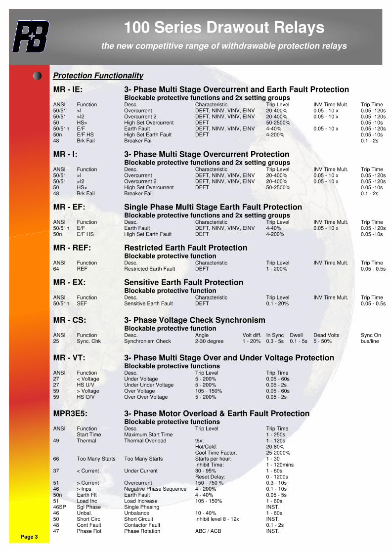
Protection Functionality
MR - IE: 3- Phase Multi Stage Overcurrent and Earth Fault Protection Blockable protective functions and 2x setting groupsANSI Function Desc. Characteristic Trip Level INV Time Mult. Trip Time50/51 >I Overcurrent DEFT, NINV, VINV, EINV 20-400% 0.05 - 10 x 0.05 -120s50/51 >I2 Overcurrent 2 DEFT, NINV, VINV, EINV 20-400% 0.05 - 10 x 0.05 -120s50 HS> High Set Overcurrent DEFT 50-2500% 0.05 -10s50/51n E/F Earth Fault DEFT, NINV, VINV, EINV 4-40% 0.05 - 10 x 0.05 -120s50n E/F HS High Set Earth Fault DEFT 4-200% 0.05 -10s48 Brk Fail Breaker Fail 0.1 - 2s
MR - I: 3- Phase Multi Stage Overcurrent Protection Blockable protective functions and 2x setting groupsANSI Function Desc. Characteristic Trip Level INV Time Mult. Trip Time50/51 >I Overcurrent DEFT, NINV, VINV, EINV 20-400% 0.05 - 10 x 0.05 -120s50/51 >I2 Overcurrent 2 DEFT, NINV, VINV, EINV 20-400% 0.05 - 10 x 0.05 -120s50 HS> High Set Overcurrent DEFT 50-2500% 0.05 -10s48 Brk Fail Breaker Fail 0.1 - 2s
MR - EF: Single Phase Multi Stage Earth Fault Protection Blockable protective functions and 2x setting groupsANSI Function Desc. Characteristic Trip Level INV Time Mult. Trip Time50/51n E/F Earth Fault DEFT, NINV, VINV, EINV 4-40% 0.05 - 10 x 0.05 -120s50n E/F HS High Set Earth Fault DEFT 4-200% 0.05 -10s
MR - REF: Restricted Earth Fault Protection Blockable protective functionANSI Function Desc. Characteristic Trip Level INV Time Mult. Trip Time64 REF Restricted Earth Fault DEFT 1 - 200% 0.05 - 0.5s
MR - EX: Sensitive Earth Fault Protection Blockable protective functionANSI Function Desc. Characteristic Trip Level INV Time Mult. Trip Time50/51n SEF Sensitive Earth Fault DEFT 0.1 - 20% 0.05 - 0.5s
MR - CS: 3- Phase Voltage Check Synchronism Blockable protective functionANSI Function Desc. Angle Volt diff. In Sync Dwell Dead Volts Sync On25 Sync. Chk Synchronism Check 2-30 degree 1 - 20% 0.3 - 5s 0.1 - 5s 5 - 50% bus/line
MR - VT: 3- Phase Multi Stage Over and Under Voltage Protection Blockable protective functionsANSI Function Desc. Trip Level Trip Time27 < Voltage Under Voltage 5 - 200% 0.05 - 60s27 HS U/V Under Under Voltage 5 - 200% 0.05 - 2s59 > Voltage Over Voltage 105 - 150% 0.05 - 60s59 HS O/V Over Over Voltage 5 - 200% 0.05 - 2s
MPR3E5: 3- Phase Motor Overload & Earth Fault Protection Blockable protective functionsANSI Function Desc. Trip Level Trip Time Start Time Maximum Start Time 1 - 250s49 Thermal Thermal Overload t6x: 1 - 120s Hot/Cold: 20-80% Cool Time Factor: 25-2000%66 Too Many Starts Too Many Starts Starts per hour: 1 - 30 Inhibit Time: 1 - 120mins37 < Current Under Current 30 - 95% 1 - 60s Reset Delay: 0 - 1200s51 > Current Overcurrent 150 - 750 % 0.3 - 10s46 > Inps Negative Phase Sequence 4 - 200% 0.1 - 10s50n Earth Flt Earth Fault 4 - 40% 0.05 - 5s51 Load Inc Load Increase 105 - 150% 1 - 60s46SP Sgl Phase Single Phasing INST.46 Unbal. Unbalance 10 - 40% 1 - 60s50 Short Circ Short Circuit Inhibit level 8 - 12x INST.48 Cont Fault Contactor Fault 0.1 - 2s47 Phase Rot Phase Rotation ABC / ACB INST.
100 Series Drawout Relays the new competitive range of withdrawable protection relays
1
3
5
7
9
11
13
15
17
19
21
23
25
27
2
4
6
8
10
12
14
16
18
20
22
24
26
28
LIVE NEUTRAL
Relay 1 NO
Relay 3 NC
Relay 2 NO
Relay 4 NO
485 +
Relay 1 NC
Relay 1 C
Digital Input 2
Relay 4 C
485 -
Relay 2 NC
Relay 2 C
Relay 3 C
Relay 3 NO
I2 Low
I3 Low
Io Low
I2 High
I3 High
485 Gnd
Relay 4 NC
Digital Input 1
I1 High
Io High
I1 Low
EARTH
17
8m
m D
OO
R S
WIN
G
215.00 mm
FITTED with 12mm M4 STUDS
34.00 mm
AN
Y F
ITT
ED
PU
SH
BU
TT
ON
S P
RO
JE
CT
LE
SS
TH
AN
10
mm
MIN 25mmFOR CABLECLEARANCE
45
.00 m
m
16
8.0
0 m
m
15
8.0
0 m
m
ø 4.3
0 mm
17
8.0
0 m
m
52.00 mm
98.00 mm
102.00 mm
23.00 mm
75.00 mm
Page 4
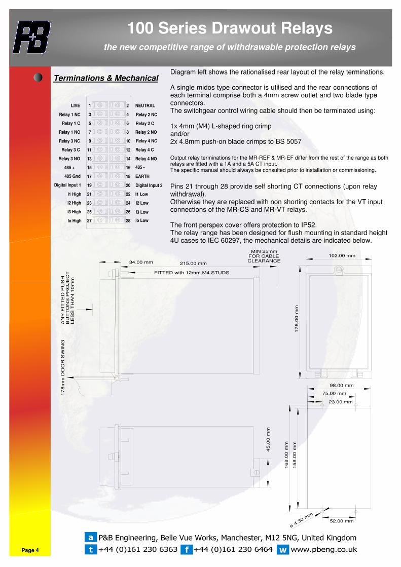
Diagram left shows the rationalised rear layout of the relay terminations.
A single midos type connector is utilised and the rear connections of each terminal comprise both a 4mm screw outlet and two blade type connectors.The switchgear control wiring cable should then be terminated using:
1x 4mm (M4) L-shaped ring crimpand/or2x 4.8mm push-on blade crimps to BS 5057
Output relay terminations for the MR-REF & MR-EF differ from the rest of the range as both relays are fitted with a 1A and a 5A CT input.The specific manual should always be consulted prior to installation or commissioning.
Pins 21 through 28 provide self shorting CT connections (upon relay withdrawal).Otherwise they are replaced with non shorting contacts for the VT input connections of the MR-CS and MR-VT relays.
The front perspex cover offers protection to IP52.The relay range has been designed for flush mounting in standard height 4U cases to IEC 60297, the mechanical details are indicated below.
t f w
a
Terminations & Mechanical


![GROUND OVER CURRENT RELAY (EARTH FAULT RELAY)[50/51N]](https://img.pdfslide.net/doc/110x75/616a4f1111a7b741a35115fa/ground-over-current-relay-earth-fault-relay5051n.jpg)