Embed Size (px)
Citation preview
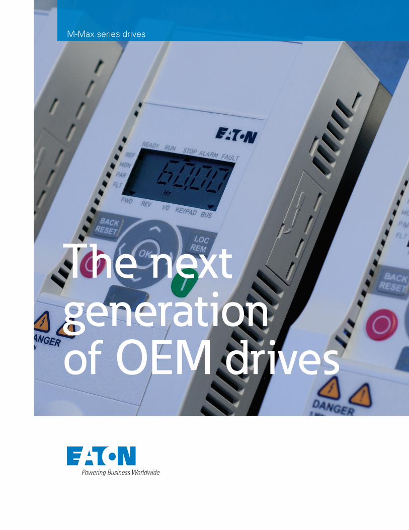
M-Max series drives
The next generation of OEM drives
Continue learning more about
Eaton drives, services and solutions.
Please visit us at:
www.eaton.com/drives
CD CONTENTS
MaxConnect® | MaxLoader® | Firmware Update
Catalog Supplement | Demo default parameter file
M-Max Series Drive publication | User Manual
Visit www.eaton.com/m-max for the
latest content updates and revisions.
EATON www.eaton.com 1
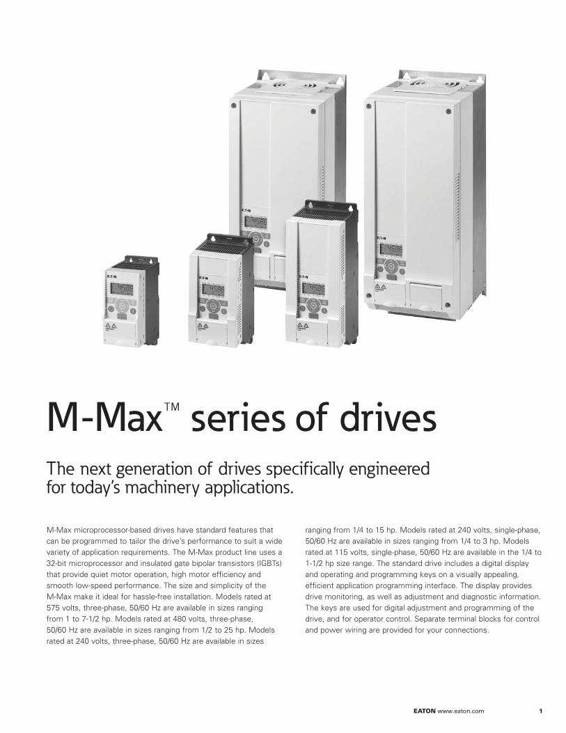
The next generation of drives specifically engineered for today’s machinery applications.
M-Max microprocessor-based drives have standard features that can be programmed to tailor the drive’s performance to suit a wide variety of application requirements. The M-Max product line uses a 32-bit microprocessor and insulated gate bipolar transistors (IGBTs) that provide quiet motor operation, high motor efficiency and smooth low-speed performance. The size and simplicity of the M-Max make it ideal for hassle-free installation. Models rated at 575 volts, three-phase, 50/60 Hz are available in sizes ranging from 1 to 7-1/2 hp. Models rated at 480 volts, three-phase, 50/60 Hz are available in sizes ranging from 1/2 to 25 hp. Models rated at 240 volts, three-phase, 50/60 Hz are available in sizes
ranging from 1/4 to 15 hp. Models rated at 240 volts, single-phase, 50/60 Hz are available in sizes ranging from 1/4 to 3 hp. Models rated at 115 volts, single-phase, 50/60 Hz are available in the 1/4 to 1-1/2 hp size range. The standard drive includes a digital display and operating and programming keys on a visually appealing, efficient application programming interface. The display provides drive monitoring, as well as adjustment and diagnostic information. The keys are used for digital adjustment and programming of the drive, and for operator control. Separate terminal blocks for control and power wiring are provided for your connections.
M-Max™ series of drives
2 EATON www.eaton.com
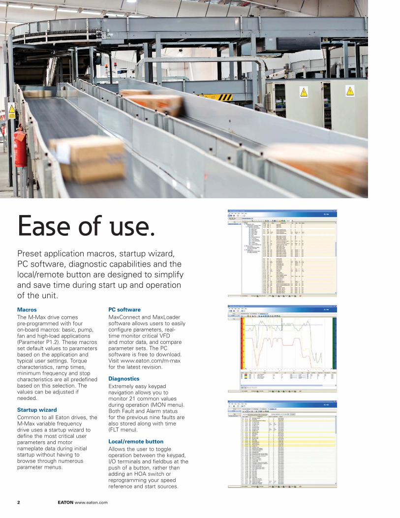
Ease of use.Preset application macros, startup wizard, PC software, diagnostic capabilities and the local/remote button are designed to simplify and save time during start up and operation of the unit.
Macros
The M-Max drive comes pre-programmed with four on-board macros: basic, pump, fan and high-load applications (Parameter P1.2). These macros set default values to parameters based on the application and typical user settings. Torque characteristics, ramp times, minimum frequency and stop characteristics are all predefined based on this selection. The values can be adjusted if needed.
Startup wizard
Common to all Eaton drives, the M-Max variable frequency drive uses a startup wizard to define the most critical user parameters and motor nameplate data during initial startup without having to browse through numerous parameter menus.
PC software
MaxConnect and MaxLoader software allows users to easily configure parameters, real- time monitor critical VFD and motor data, and compare parameter sets. The PC software is free to download. Visit www.eaton.com/m-max for the latest revision.
Diagnostics
Extremely easy keypad navigation allows you to monitor 21 common values during operation (MON menu). Both Fault and Alarm status for the previous nine faults are also stored along with time (FLT menu).
Local/remote button
Allows the user to toggle operation between the keypad, I/O terminals and fieldbus at the push of a button, rather than adding an HOA switch or reprogramming your speed reference and start sources.
EATON www.eaton.com 3
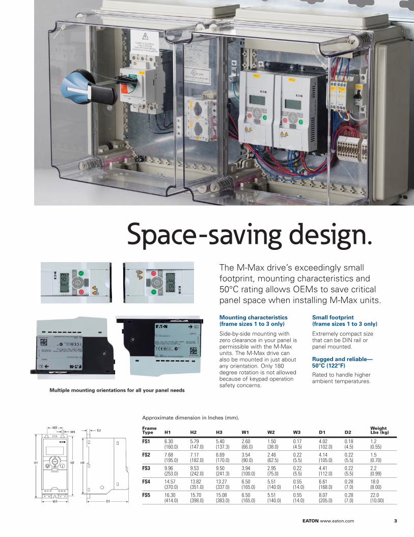
Space-saving design.
Mounting characteristics (frame sizes 1 to 3 only)
Side-by-side mounting with zero clearance in your panel is permissible with the M-Max units. The M-Max drive can also be mounted in just about any orientation. Only 180 degree rotation is not allowed because of keypad operation safety concerns.
Small footprint (frame sizes 1 to 3 only)
Extremely compact size that can be DIN rail or panel mounted.
Rugged and reliable— 50°C (122°F)
Rated to handle higher ambient temperatures.
Frame Type H1 H2 H3 W1 W2 W3 D1 D2
Weight Lbs (kg)
FS1 6.30 (160.0)
5.79 (147.0)
5.40 (137.3)
2.60 (66.0)
1.50 (38.0)
0.17 (4.5)
4.02 (102.0)
0.18 (4.5)
1.2 (0.55)
FS2 7.68 (195.0)
7.17 (182.0)
6.69 (170.0)
3.54 (90.0)
2.46 (62.5)
0.22 (5.5)
4.14 (105.0)
0.22 (5.5)
1.5 (0.70)
FS3 9.96 (253.0)
9.53 (242.0)
9.50 (241.3)
3.94 (100.0)
2.95 (75.0)
0.22 (5.5)
4.41 (112.0)
0.22 (5.5)
2.2 (0.99)
FS4 14.57 (370.0)
13.82 (351.0)
13.27 (337.0)
6.50 (165.0)
5.51 (140.0)
0.55 (14.0)
6.61 (168.0)
0.28 (7.0)
18.0 (8.00)
FS5 16.30 (414.0)
15.70 (398.0)
15.08 (383.0)
6.50 (165.0)
5.51 (140.0)
0.55 (14.0)
8.07 (205.0)
0.28 (7.0)
22.0 (10.00)
Multiple mounting orientations for all your panel needs
Approximate dimension in Inches (mm).
The M-Max drive’s exceedingly small footprint, mounting characteristics and 50°C rating allows OEMs to save critical panel space when installing M-Max units.
4 EATON www.eaton.com
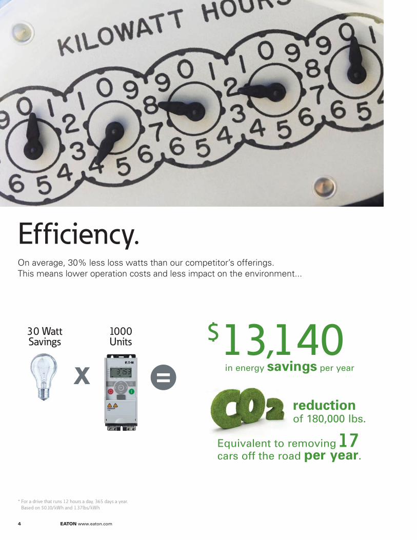
* For a drive that runs 12 hours a day, 365 days a year.
Based on $0.10/kWh and 1.37lbs/kWh
reduction of 180,000 lbs.
Equivalent to removing 17 cars off the road per year.
$ 13,140in energy savings per year
1000 Units
30 Watt Savings
x =
Efficiency.On average, 30% less loss watts than our competitor’s offerings. This means lower operation costs and less impact on the environment...
EATON www.eaton.com 5
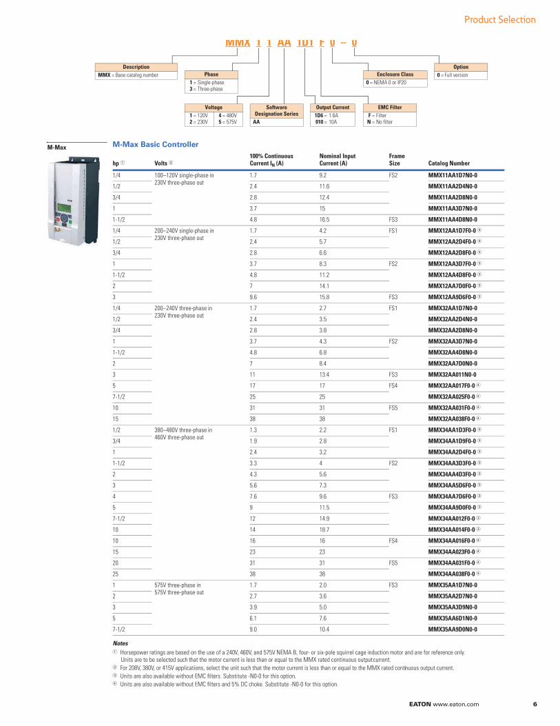
Temp-controlled fan
Internal temperature sensors start the cooling fan when needed, instead of continuously running. Extends fan life, which extends VFD life.
50°C (122°F)
Rated to handle higher ambient termperatures.
Conformal coating
Protective coating for printed circuit boards. It protects and insulates against moisture, corrosion, dust, and thermal shock.
High overload rating
150% for 1 minute each 10 minutes or 200% for 2 seconds each 20 seconds. Meets constant torque applications.
NEMA® 1 enclosures
Available for all frame sizes to meet NEMA 1 and IP21 requirements. Includes conduit entry plate.
EMC filters
Type C2 protection integrated into the unit on single-phase 230V and three-phase 480V units.
Brake chopper circuit
Integrated into three-phase FS2, FS3, FS4 and FS5 units.
Global acceptanceDesigned and tested to meet the standards of the global market.
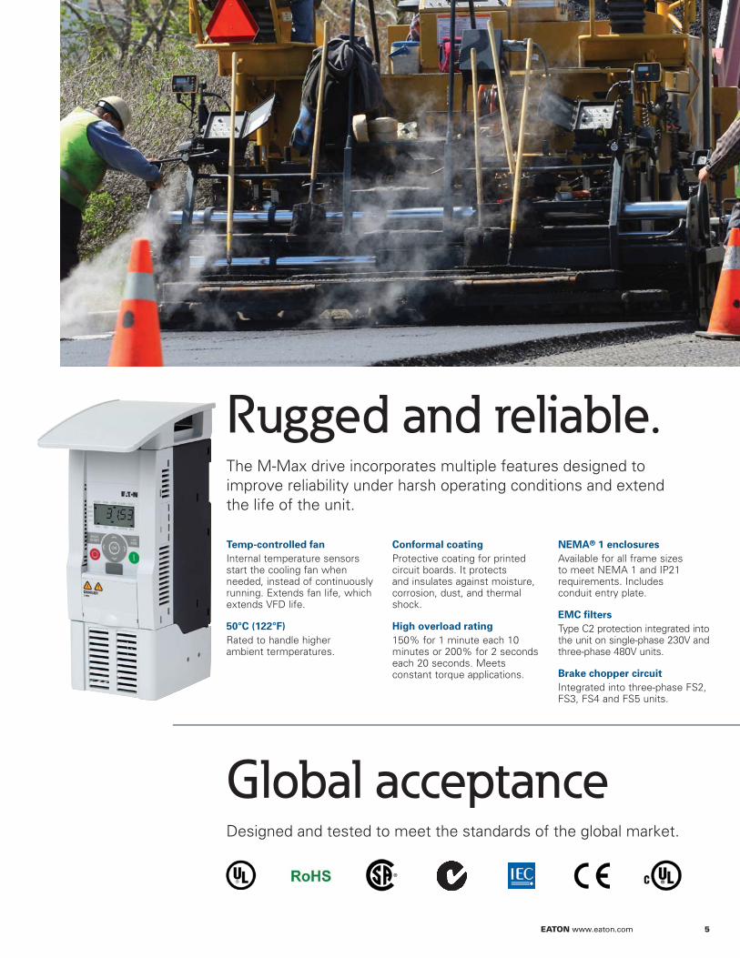
Rugged and reliable. The M-Max drive incorporates multiple features designed to improve reliability under harsh operating conditions and extend the life of the unit.

Pro
du
ct Se
lectio
n
EATON www.eaton.com 6
Product Selection
Software Designation Series
AA
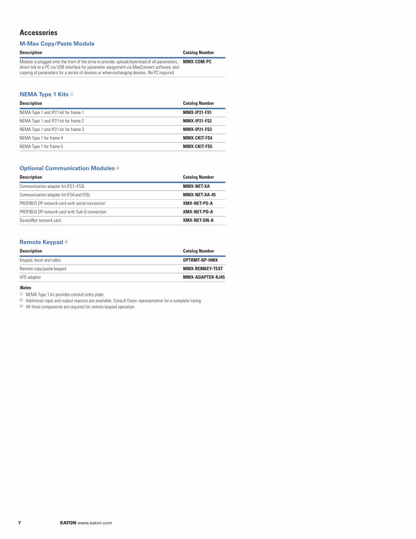
Description
MMX = Base catalog number
MMX 1 1 AA 1D1 F 0 – 0
Phase
1 = Single-phase3 = Three-phase
Voltage
1 = 120V2 = 230V
4 = 480V5 = 575V
Output Current
1D6 = 1.6A010 = 10A
EMC Filter
F = FilterN = No filter
Enclosure Class
0 = NEMA 0 or IP20
Option
0 = Full version
M-Max Basic Controller
NotesHorsepower ratings are based on the use of a 240V, 460V, and 575V NEMA B, four- or six-pole squirrel cage induction motor and are for reference only. Units are to be selected such that the motor current is less than or equal to the MMX rated continuous output current.For 208V, 380V, or 415V applications, select the unit such that the motor current is less than or equal to the MMX rated continuous output current.Units are also available without EMC filters. Substitute -N0-0 for this option.Units are also available without EMC filters and 5% DC choke. Substitute -N0-0 for this option.
hp Volts 100% Continuous Current IN (A)
Nominal Input Current (A)
FrameSize Catalog Number
1/4 100–120V single-phase in230V three-phase out
1.7 9.2 FS2 MMX11AA1D7N0-0
1/2 2.4 11.6 MMX11AA2D4N0-0
3/4 2.8 12.4 MMX11AA2D8N0-0
1 3.7 15 MMX11AA3D7N0-0
1-1/2 4.8 16.5 FS3 MMX11AA4D8N0-0
1/4 200–240V single-phase in230V three-phase out
1.7 4.2 FS1 MMX12AA1D7F0-0
1/2 2.4 5.7 MMX12AA2D4F0-0
3/4 2.8 6.6 MMX12AA2D8F0-0
1 3.7 8.3 FS2 MMX12AA3D7F0-0
1-1/2 4.8 11.2 MMX12AA4D8F0-0
2 7 14.1 MMX12AA7D0F0-0
3 9.6 15.8 FS3 MMX12AA9D6F0-0
1/4 200–240V three-phase in230V three-phase out
1.7 2.7 FS1 MMX32AA1D7N0-0
1/2 2.4 3.5 MMX32AA2D4N0-0
3/4 2.8 3.8 MMX32AA2D8N0-0
1 3.7 4.3 FS2 MMX32AA3D7N0-0
1-1/2 4.8 6.8 MMX32AA4D8N0-0
2 7 8.4 MMX32AA7D0N0-0
3 11 13.4 FS3 MMX32AA011N0-0
5 17 17 FS4 MMX32AA017F0-0
7-1/2 25 25 MMX32AA025F0-0
10 31 31 FS5 MMX32AA031F0-0
15 38 38 MMX32AA038F0-0
1/2 380–480V three-phase in460V three-phase out
1.3 2.2 FS1 MMX34AA1D3F0-0
3/4 1.9 2.8 MMX34AA1D9F0-0
1 2.4 3.2 MMX34AA2D4F0-0
1-1/2 3.3 4 FS2 MMX34AA3D3F0-0
2 4.3 5.6 MMX34AA4D3F0-0
3 5.6 7.3 MMX34AA5D6F0-0
4 7.6 9.6 FS3 MMX34AA7D6F0-0
5 9 11.5 MMX34AA9D0F0-0
7-1/2 12 14.9 MMX34AA012F0-0
10 14 18.7 MMX34AA014F0-0
10 16 16 FS4 MMX34AA016F0-0
15 23 23 MMX34AA023F0-0
20 31 31 FS5 MMX34AA031F0-0
25 38 38 MMX34AA038F0-0
1 575V three-phase in575V three-phase out
1.7 2.0 FS3 MMX35AA1D7N0-0
2 2.7 3.6 MMX35AA2D7N0-0
3 3.9 5.0 MMX35AA3D9N0-0
5 6.1 7.6 MMX35AA6D1N0-0
7-1/2 9.0 10.4 MMX35AA9D0N0-0
M-Max
7 EATON www.eaton.com
Accessories
M-Max Copy/Paste Module
NEMA Type 1 Kits
Optional Communication Modules
Remote Keypad
NotesNEMA Type 1 kit provides conduit entry plate. Additional input and output reactors are available. Consult Eaton representative for a complete listing. All three components are required for remote keypad operation.
Description
Module is plugged onto the front of the drive to provide: upload/download of all parameters, direct link to a PC via USB interface for parameter assignment via MaxConnect software, and copying of parameters for a series of devices or when exchanging devices. No PC required
MMX-COM-PC
Description
NEMA Type 1 and IP21 kit for frame 1 MMX-IP21-FS1
NEMA Type 1 and IP21 kit for frame 2 MMX-IP21-FS2
NEMA Type 1 and IP21 kit for frame 3 MMX-IP21-FS3
NEMA Type 1 for frame 4 MMX-CKIT-FS4
NEMA Type 1 for frame 5 MMX-CKIT-FS5
Description
Communication adapter kit (FS1–FS3) MMX-NET-XA
Communication adapter kit (FS4 and FS5) MMX-NET-XA-45
PROFIBUS DP network card with serial connection XMX-NET-PS-A
PROFIBUS DP network card with Sub-D connection XMX-NET-PD-A
DeviceNet network card XMX-NET-DN-A
Description Catalog Number
Keypad, bezel and cable OPTRMT-BP-HMX
Remote copy/paste keypad MMX-REMKEY-TEXT
VFD adapter MMX-ADAPTER-RJ45
Catalog Number
Catalog Number
Catalog Number
EATON www.eaton.com 8
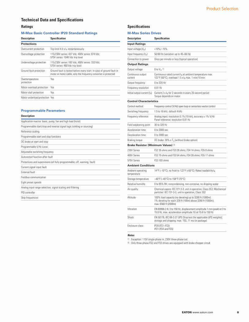
Technical Data and Specifications
Ratings
M-Max Basic Controller IP20 Standard Ratings
Programmable Parameters
Specifications
M-Max Series Drives
NotesException: 115V single-phase in, 230V three-phase out.Only three-phase FS2 and FS3 drives are equipped with brake chopper circuit.
Description Specification
Protections
Overcurrent protection Trip limit 4.0 x IH instantaneously
Overvoltage protection 115/230V series: 437 Vdc; 400V series: 874 Vdc; 575V series: 1048 Vdc trip level
Undervoltage protection 115/230V series: 183 Vdc; 400V series: 333 Vdc; 575V series: 460 Vdc trip level
Ground fault protection Ground fault is tested before every start. In case of ground fault in motor or motor cable, only the frequency converter is protected
Overtemperature protection
Yes
Motor overload protection Yes
Motor stall protection Yes
Motor underload protection Yes
Description
Application macros: basic, pump, fan and high load (hoist)
Programmable start/stop and reverse signal logic (sinking or sourcing)
Reference scaling
Programmable start and stop functions
DC-brake at start and stop
Programmable V/Hz curve
Adjustable switching frequency
Autorestart function after fault
Protections and supervisions (all fully programmable; off, warning, fault)
Current signal input fault
External fault
Fieldbus communication
Eight preset speeds
Analog input range selection, signal scaling and filtering
PID controller
Skip frequencies
Description Specification
Input Ratings
Input voltage (Vin) +10%/–15%
Input frequency (fin) 50/60 Hz (variation up to 45–66 Hz)
Connection to power Once per minute or less (typical operation)
Output Ratings
Output voltage 0 to Vin
Continuous output current
Continuous rated current IN at ambient temperature max. 122°F (50°C), overload 1.5 x IN max. 1 min/10 min
Output frequency 0 to 320 Hz
Frequency resolution 0.01 Hz
Initial output current (IH) Current 2 x IN for 2 seconds in every 20-second period Torque depends on motor
Control Characteristics
Control method Frequency control (V/Hz) open loop or sensorless vector control
Switching frequency 1.5 to 16 kHz; default 4 kHz
Frequency reference Analog input: resolution 0.1% (10-bit), accuracy ± 1% V/Hz Panel reference: resolution 0.01 Hz
Field weakening point 30 to 320 Hz
Acceleration time 0 to 3000 sec
Deceleration time 0 to 3000 sec
Braking torque DC brake: 30% x Tn (without brake option)
Brake Resistor (Minimum Values)
230V Series FS2 35 ohms and FS3 26 ohms, FS4 14 ohms, FS5 9 ohms
400V Series FS2 75 ohms and FS3 54 ohms, FS4 28 ohms, FS5 17 ohms
575V Series FS3 103 ohms
Ambient Conditions
Ambient operating temperature
14°F (–10°C), no frost to 122°F (+50°C): Rated loadability IN
Storage temperature –40°F (–40°C) to 158°F (70°C)
Relative humidity 0 to 95% RH, noncondensing, non-corrosive, no dripping water
Air quality Chemical vapors: IEC 721-3-3, unit in operation, Class 3C2; Mechanical particles: IEC 721-3-3, unit in operation, Class 3S2
Altitude 100% load capacity (no derating) up to 3280 ft (1000m); 1% derating for each 328 ft (100m) above 3280 ft (1000m); max. 6560 ft (2000m)
Vibration EN 60068-2-6; 3 to 150 Hz, displacement amplitude 1 mm (peak) at 3 to 15.8 Hz, max. acceleration amplitude 1G at 15.8 to 150 Hz
Shock EN 50178, IEC 68-2-27 UPS Drop test (for applicable UPS weights); storage and shipping: max. 15G, 11 ms (in package)
Enclosure class IP20 (FS1–FS3)IP21 (FS4 and FS5)
Product Selection
9 EATON www.eaton.com
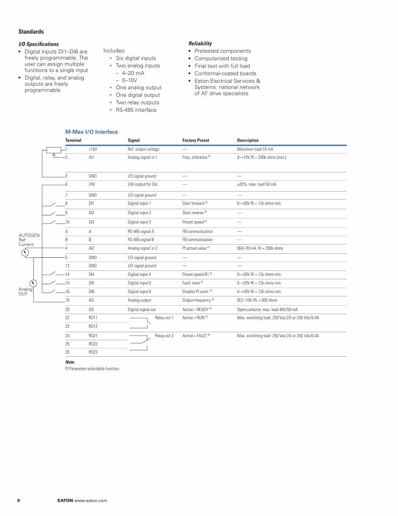
Standards
I/O SpecificationsDigital inputs DI1–DI6 are freely programmable. The user can assign multiple functions to a single input
Digital, relay, and analog outputs are freely programmable
Includes:
Six digital inputs
Two analog inputs
– 4–20 mA– 0–10VOne analog output
One digital output
Two relay outputs
RS-485 interface
ReliabilityPretested components
Computerized testing
Final test with full load
Conformal-coated boards
Eaton Electrical Services & Systems: national network of AF drive specialists
M-Max I/O Interface
NoteP) Parameter-selectable function.
Terminal Signal Factory Preset Description
1 +10V Ref. output voltage — Maximum load 10 mA
2 AI1 Analog signal in 1 Freq. reference P) 0–+10V Ri = 200k ohms [min.]
3 GND I/O signal ground — —
6 24V 24V output for DIs — ±20%, max. load 50 mA
7 GND I/O signal ground — —
8 DI1 Digital input 1 Start forward P) 0–+30V Ri = 12k ohms min.
9 DI2 Digital input 2 Start reverse P) —
10 DI3 Digital input 3 Preset speed P) —
A A RS-485 signal A FB communication —
B B RS-485 signal B FB communication —
4 AI2 Analog signal in 2 PI actual value P) 0[4]–20 mA, Ri = 200k ohms
5 GND I/O signal ground — —
13 GND I/O signal ground — —
14 DI4 Digital input 4 Preset speed B1 P) 0–+30V Ri = 12k ohms min.
15 DI5 Digital input 5 Fault reset P) 0–+30V Ri = 12k ohms min.
16 DI6 Digital input 6 Disable PI contr. P) 0–+30V Ri = 12k ohms min.
18 AO Analog output Output frequency P) 0(2)–10V, RL = 500 ohms
20 DO Digital signal out Active = READY P) Open collector, max. load 48V/50 mA
22 RO11 Relay out 1 Active = RUN P) Max. switching load: 250 Vac/2A or 250 Vdc/0.4A
23 RO12
24 RO21 Relay out 2 Active = FAULT P) Max. switching load: 250 Vac/2A or 250 Vdc/0.4A
25 RO22
26 RO23
AnalogOUT
AUTOGENRefCurrent
EATON www.eaton.com 10
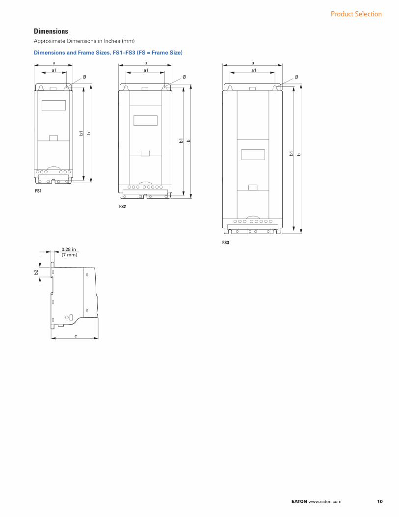
Dimensions and Frame Sizes, FS1–FS3 (FS = Frame Size)
b1 b
a1
a
b1 b
a1
a
b1
b
a1
a
b2
c
0.28 in(7 mm)
FS1
FS2
FS3
Approximate Dimensions in Inches (mm)
Dimensions
Product Selection
11 EATON www.eaton.com
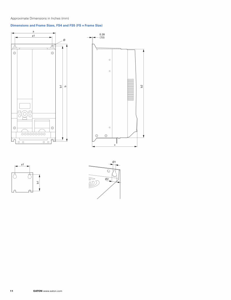
Approximate Dimensions in Inches (mm)
Dimensions and Frame Sizes, FS4 and FS5 (FS = Frame Size)
b1
a1
b2
c
b1 b
a1
a
Ø
0.28(7.0)
Ø1
Ø2
EATON www.eaton.com 12
Product Selection
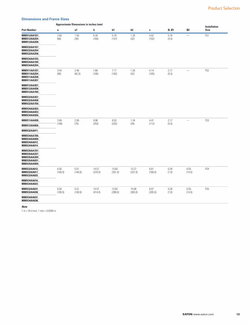
Dimensions and Frame Sizes
Note1 in = 25.4 mm, 1 mm = 0.0394 in
Approximate Dimensions in inches (mm)Installation SizePart Number a a1 b b1 b2 c Ø, Ø1 Ø2
MMX12AA1D7_MMX12AA2D4_MMX12AA2D8_
2.60(66)
1.50(38)
6.30(160)
5.79(147)
1.26(32)
4.02(102)
0.18(4.5)
— FS1
MMX32AA1D7_MMX32AA2D4_MMX32AA2D8_
MMX34AA1D3_MMX34AA1D9_MMX34AA2D4_
MMX11AA1D7_MMX11AA2D4_MMX11AA2D8_MMX11AA3D7_
3.54(90)
2.46(62.5)
7.68(195)
7.17(182)
1.26(32)
4.14(105)
2.17(5.5)
— FS2
MMX12AA3D7_MMX12AA4D8_MMX12AA7D0_
MMX32AA3D7_MMX32AA4D8_MMX32AA7D0_
MMX34AA3D3_MMX34AA4D3_MMX34AA5D6_
MMX11AA4D8_ 3.94(100)
2.95(75)
9.96(253)
9.53(242)
1.34(34)
4.41(112)
2.17(5.5)
— FS3
MMX12AA9D6_
MMX32AA011_
MMX34AA7D6_MMX34AA9D0_MMX34AA012_MMX34AA014_
MMX35AA1D7_MMX35AA2D7_MMX35AA3D9_MMX35AA6D1_MMX35AA9D0_
MMX32AA012_MMX32AA017_MMX32AA025_
6.50(165.0)
5.51(140.0)
14.57(370.0)
13.82(351.0)
13.27(337.0)
6.61(168.0)
0.28(7.0)
0.55(14.0)
FS4
MMX34AA016_MMX34AA023_
MMX32AA031_MMX32AA038_
6.50(165.0)
5.51(140.0)
14.57(414.0)
13.82(398.0)
15.08(383.0)
8.07(205.0)
0.28(7.0)
0.55(14.0)
FS5
MMX34AA031_MMX34AA038_

Pa
rame
ter G
uid
e
EATON www.eaton.com 13
Parameter Guide
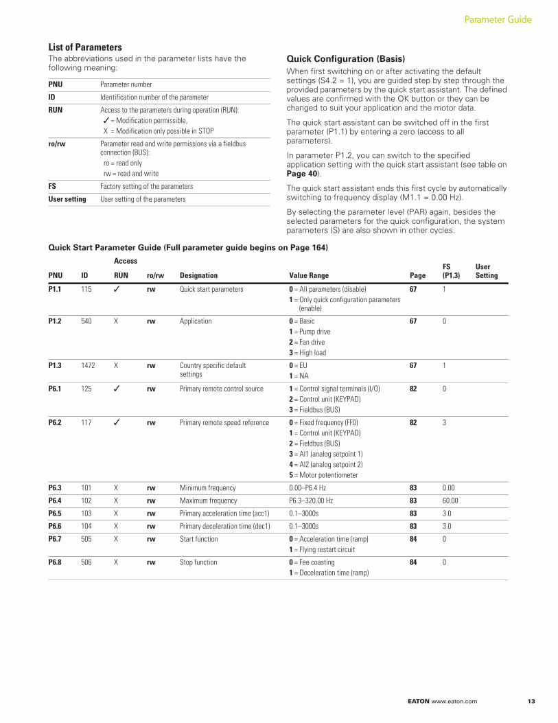
List of ParametersThe abbreviations used in the parameter lists have the following meaning:
Quick Configuration (Basis)
When first switching on or after activating the default settings (S4.2 = 1), you are guided step by step through the provided parameters by the quick start assistant. The defined values are confirmed with the OK button or they can be changed to suit your application and the motor data.
The quick start assistant can be switched off in the first parameter (P1.1) by entering a zero (access to all parameters).
In parameter P1.2, you can switch to the specified application setting with the quick start assistant (see table on Page 40).
The quick start assistant ends this first cycle by automatically switching to frequency display (M1.1 = 0.00 Hz).
By selecting the parameter level (PAR) again, besides the selected parameters for the quick configuration, the system parameters (S) are also shown in other cycles.
Quick Start Parameter Guide (Full parameter guide begins on Page 164)
PNU Parameter number
ID Identification number of the parameter
RUN Access to the parameters during operation (RUN): = Modification permissible,
X = Modification only possible in STOP
ro/rw Parameter read and write permissions via a fieldbus connection (BUS):ro = read onlyrw = read and write
FS Factory setting of the parameters
User setting User setting of the parameters
PNU ID
Access
Designation Value Range Page FS(P1.3)
User SettingRUN ro/rw
P1.1 115 rw Quick start parameters 0 = All parameters (disable)1 = Only quick configuration parameters
(enable)
67 1
P1.2 540 X rw Application 0 = Basic1 = Pump drive2 = Fan drive3 = High load
67 0
P1.3 1472 X rw Country specific default settings
0 = EU1 = NA
67 1
P6.1 125 rw Primary remote control source 1 = Control signal terminals (I/O)2 = Control unit (KEYPAD)3 = Fieldbus (BUS)
82 0
P6.2 117 rw Primary remote speed reference 0 = Fixed frequency (FF0)1 = Control unit (KEYPAD)2 = Fieldbus (BUS)3 = AI1 (analog setpoint 1)4 = AI2 (analog setpoint 2)5 = Motor potentiometer
82 3
P6.3 101 X rw Minimum frequency 0.00–P6.4 Hz 83 0.00
P6.4 102 X rw Maximum frequency P6.3–320.00 Hz 83 60.00
P6.5 103 X rw Primary acceleration time (acc1) 0.1–3000s 83 3.0
P6.6 104 X rw Primary deceleration time (dec1) 0.1–3000s 83 3.0
P6.7 505 X rw Start function 0 = Acceleration time (ramp)1 = Flying restart circuit
84 0
P6.8 506 X rw Stop function 0 = Fee coasting1 = Deceleration time (ramp)
84 0
14 EATON www.eaton.com
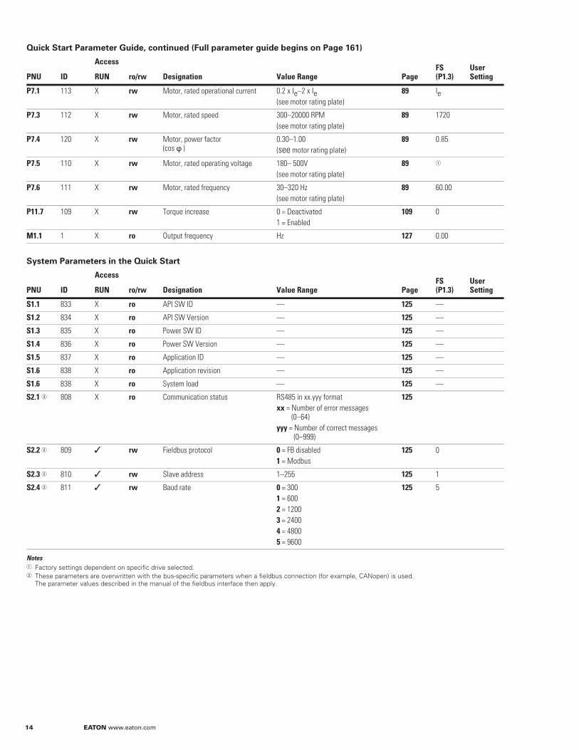
Quick Start Parameter Guide, continued (Full parameter guide begins on Page 161)
System Parameters in the Quick Start
NotesFactory settings dependent on specific drive selected.These parameters are overwritten with the bus-specific parameters when a fieldbus connection (for example, CANopen) is used. The parameter values described in the manual of the fieldbus interface then apply.
PNU ID
Access
Designation Value Range Page FS(P1.3)
User SettingRUN ro/rw
P7.1 113 X rw Motor, rated operational current 0.2 x Ie–2 x Ie(see motor rating plate)
89 Ie
P7.3 112 X rw Motor, rated speed 300–20000 RPM(see motor rating plate)
89 1720
P7.4 120 X rw Motor, power factor (cos )
0.30–1.00(see motor rating plate)
89 0.85
P7.5 110 X rw Motor, rated operating voltage 180– 500V(see motor rating plate)
89
P7.6 111 X rw Motor, rated frequency 30–320 Hz(see motor rating plate)
89 60.00
P11.7 109 X rw Torque increase 0 = Deactivated1 = Enabled
109 0
M1.1 1 X ro Output frequency Hz 127 0.00
PNU ID
Access
Designation Value Range Page FS(P1.3)
User SettingRUN ro/rw
S1.1 833 X ro API SW ID — 125 —
S1.2 834 X ro API SW Version — 125 —
S1.3 835 X ro Power SW ID — 125 —
S1.4 836 X ro Power SW Version — 125 —
S1.5 837 X ro Application ID — 125 —
S1.6 838 X ro Application revision — 125 —
S1.6 838 X ro System load — 125 —
S2.1 808 X ro Communication status RS485 in xx.yyy formatxx = Number of error messages
(0–64)yyy = Number of correct messages
(0–999)
125
S2.2 809 rw Fieldbus protocol 0 = FB disabled1 = Modbus
125 0
S2.3 810 rw Slave address 1–255 125 1
S2.4 811 rw Baud rate 0 = 3001 = 6002 = 12003 = 24004 = 48005 = 9600
125 5
EATON www.eaton.com 15
Parameter Guide
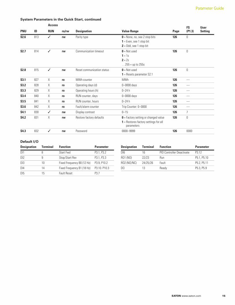
System Parameters in the Quick Start, continued
Default I/O
PNU ID
Access
Designation Value Range Page FS(P1.3)
User SettingRUN ro/rw
S2.6 813 rw Parity type 0 = None, no, see 2 stop bits1 = Even, see 1 stop bit2 = Odd, see 1 stop bit
126 0
S2.7 814 rw Communication timeout 0 = Not used1 = 1s2 = 2s…255 = up to 255s
126 0
S2.8 815 rw Reset communication status 0 = Not used1 = Resets parameter S2.1
126 0
S3.1 827 X ro MWh counter MWh 126 —
S3.2 828 X ro Operating days (d) 0–0000 days 126 —
S3.3 829 X ro Operating hours (h) 0–24 h 126 —
S3.4 840 X ro RUN counter, days 0–0000 days 126 —
S3.5 841 X ro RUN counter, hours 0–24 h 126 —
S3.6 842 X ro Fault/alarm counter Trip Counter: 0–0000 126 —
S4.1 830 rw Display contrast 0–15 126 7
S4.2 831 X rw Restore factory defaults 0 = Factory setting or changed value1 = Restores factory settings for all
parameters
126 0
S4.3 832 rw Password 0000–9999 126 0000
Designation Terminal Function Parameter Designation Terminal Function Parameter
DI1 8 Start Fwd P3.1, P3.2 DI6 16 PID Controller Deactivate P3.12
DI2 9 Stop/Start Rev P3.1, P3.3 RO1 (NO) 22/23 Run P5.1, P5.10
DI3 10 Fixed Frequency B0 (12 Hz) P3.9, P10.2 RO2 (NO/NC) 24/25/26 Fault P5.2, P5.11
DI4 14 Fixed Frequency B1 (18 Hz) P3.10. P10.3 DO 13 Ready P5.3, P5.9
DI5 15 Fault Reset P3.7
16 EATON www.eaton.com
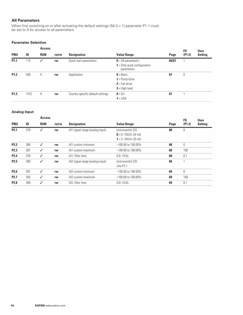
All Parameters
When first switching on or after activating the default settings (S4.2 = 1) parameter P1.1 must be set to 0 for access to all parameters.
Parameter Selection
Analog Input
PNU ID
Access
Designation Value Range Page FS(P1.3)
User SettingRUN ro/rw
P1.1 115 rw Quick start parameters 0 = All parameters1 = Only quick configuration
parameters
66/67 1
P1.2 540 X rw Application 0 = Basic1 = Pump drive2 = Fan drive3 = High load
67 0
P1.3 1472 X rw Country specific default settings 0 = EU1 = USA
67 1
PNU ID
Access
Designation Value Range Page FS(P1.3)
User SettingRUN ro/rw
P2.1 379 rw AI1 signal range (analog input) (microswitch S2)0 = 0–10V/0–20 mA1 = 2–10V/4–20 mA
68 0
P2.2 380 rw AI1 custom minimum –100.00 to 100.00% 68 0
P2.3 381 rw AI1 custom maximum –100.00 to 100.00% 68 100
P2.4 378 rw AI1, filter time 0.0–10.0s 68 0.1
P2.5 390 rw AI2 signal range (analog input) (microswitch S3)Like P2.1
69 1
P2.6 391 rw AI2 custom minimum –100.00 to 100.00% 69 0
P2.7 392 rw AI2 custom maximum –100.00 to 100.00% 69 100
P2.8 389 rw AI2, filter time 0.0–10.0s 69 0.1
EATON www.eaton.com 17
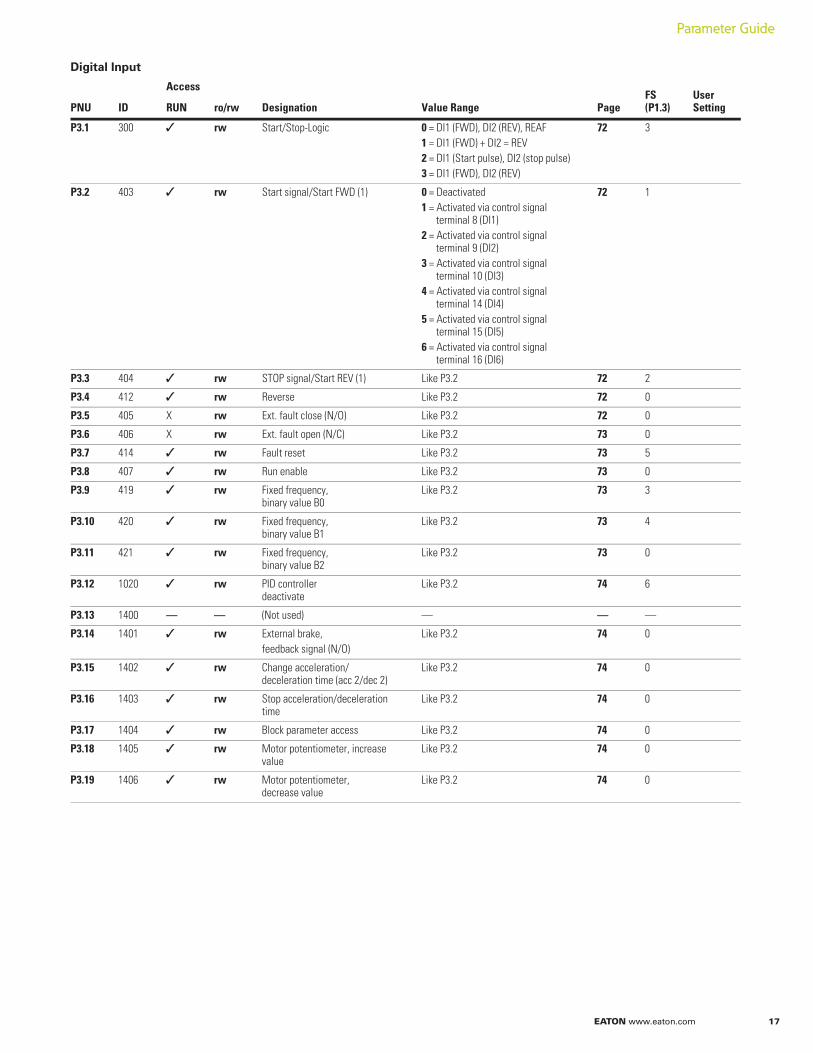
Digital Input
PNU ID
Access
Designation Value Range Page FS(P1.3)
User SettingRUN ro/rw
P3.1 300 rw Start/Stop-Logic 0 = DI1 (FWD), DI2 (REV), REAF1 = DI1 (FWD) + DI2 = REV2 = DI1 (Start pulse), DI2 (stop pulse)3 = DI1 (FWD), DI2 (REV)
72 3
P3.2 403 rw Start signal/Start FWD (1) 0 = Deactivated1 = Activated via control signal
terminal 8 (DI1)2 = Activated via control signal
terminal 9 (DI2)3 = Activated via control signal
terminal 10 (DI3)4 = Activated via control signal
terminal 14 (DI4)5 = Activated via control signal
terminal 15 (DI5)6 = Activated via control signal
terminal 16 (DI6)
72 1
P3.3 404 rw STOP signal/Start REV (1) Like P3.2 72 2
P3.4 412 rw Reverse Like P3.2 72 0
P3.5 405 X rw Ext. fault close (N/O) Like P3.2 72 0
P3.6 406 X rw Ext. fault open (N/C) Like P3.2 73 0
P3.7 414 rw Fault reset Like P3.2 73 5
P3.8 407 rw Run enable Like P3.2 73 0
P3.9 419 rw Fixed frequency, binary value B0
Like P3.2 73 3
P3.10 420 rw Fixed frequency, binary value B1
Like P3.2 73 4
P3.11 421 rw Fixed frequency, binary value B2
Like P3.2 73 0
P3.12 1020 rw PID controller deactivate
Like P3.2 74 6
P3.13 1400 — — (Not used) — — —
P3.14 1401 rw External brake, feedback signal (N/O)
Like P3.2 74 0
P3.15 1402 rw Change acceleration/deceleration time (acc 2/dec 2)
Like P3.2 74 0
P3.16 1403 rw Stop acceleration/deceleration time
Like P3.2 74 0
P3.17 1404 rw Block parameter access Like P3.2 74 0
P3.18 1405 rw Motor potentiometer, increase value
Like P3.2 74 0
P3.19 1406 rw Motor potentiometer, decrease value
Like P3.2 74 0
Parameter Guide
18 EATON www.eaton.com
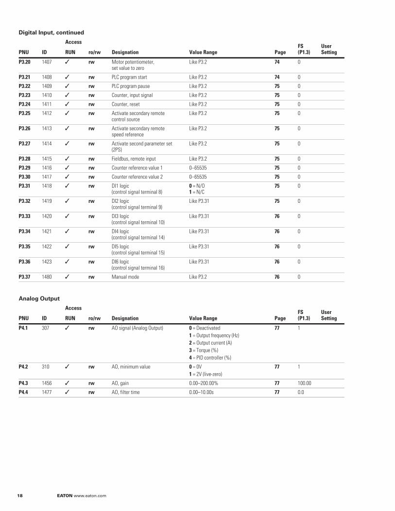
Digital Input, continued
Analog Output
PNU ID
Access
Designation Value Range Page FS(P1.3)
User SettingRUN ro/rw
P3.20 1407 rw Motor potentiometer, set value to zero
Like P3.2 74 0
P3.21 1408 rw PLC program start Like P3.2 74 0
P3.22 1409 rw PLC program pause Like P3.2 75 0
P3.23 1410 rw Counter, input signal Like P3.2 75 0
P3.24 1411 rw Counter, reset Like P3.2 75 0
P3.25 1412 rw Activate secondary remote control source
Like P3.2 75 0
P3.26 1413 rw Activate secondary remote speed reference
Like P3.2 75 0
P3.27 1414 rw Activate second parameter set (2PS)
Like P3.2 75 0
P3.28 1415 rw Fieldbus, remote input Like P3.2 75 0
P3.29 1416 rw Counter reference value 1 0–65535 75 0
P3.30 1417 rw Counter reference value 2 0–65535 75 0
P3.31 1418 rw DI1 logic (control signal terminal 8)
0 = N/O1 = N/C
75 0
P3.32 1419 rw DI2 logic (control signal terminal 9)
Like P3.31 75 0
P3.33 1420 rw DI3 logic (control signal terminal 10)
Like P3.31 76 0
P3.34 1421 rw DI4 logic (control signal terminal 14)
Like P3.31 76 0
P3.35 1422 rw DI5 logic (control signal terminal 15)
Like P3.31 76 0
P3.36 1423 rw DI6 logic (control signal terminal 16)
Like P3.31 76 0
P3.37 1480 rw Manual mode Like P3.2 76 0
PNU ID
Access
Designation Value Range Page FS(P1.3)
User SettingRUN ro/rw
P4.1 307 rw AO signal (Analog Output) 0 = Deactivated1 = Output frequency (Hz)2 = Output current (A)3 = Torque (%)4 = PID controller (%)
77 1
P4.2 310 rw AO, minimum value 0 = 0V1 = 2V (live-zero)
77 1
P4.3 1456 rw AO, gain 0.00–200.00% 77 100.00
P4.4 1477 rw AO, filter time 0.00–10.00s 77 0.0
EATON www.eaton.com 19
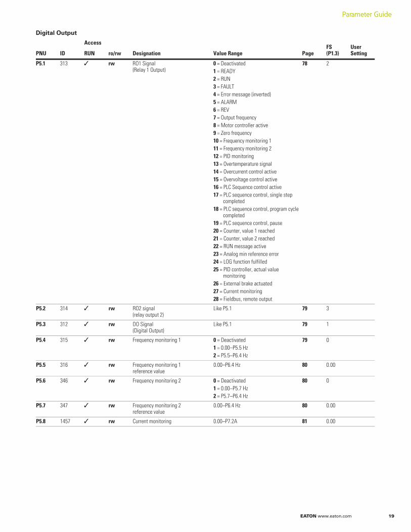
Digital Output
PNU ID
Access
Designation Value Range Page FS(P1.3)
User SettingRUN ro/rw
P5.1 313 rw RO1 Signal (Relay 1 Output)
0 = Deactivated1 = READY2 = RUN3 = FAULT4 = Error message (inverted)5 = ALARM6 = REV7 = Output frequency8 = Motor controller active9 = Zero frequency10 = Frequency monitoring 111 = Frequency monitoring 212 = PID monitoring13 = Overtemperature signal14 = Overcurrent control active15 = Overvoltage control active16 = PLC Sequence control active17 = PLC sequence control, single step
completed18 = PLC sequence control, program cycle
completed19 = PLC sequence control, pause20 = Counter, value 1 reached21 = Counter, value 2 reached22 = RUN message active23 = Analog min reference error24 = LOG function fulfilled25 = PID controller, actual value
monitoring26 = External brake actuated27 = Current monitoring28 = Fieldbus, remote output
78 2
P5.2 314 rw RO2 signal (relay output 2)
Like P5.1 79 3
P5.3 312 rw DO Signal (Digital Output)
Like P5.1 79 1
P5.4 315 rw Frequency monitoring 1 0 = Deactivated1 = 0.00–P5.5 Hz2 = P5.5–P6.4 Hz
79 0
P5.5 316 rw Frequency monitoring 1reference value
0.00–P6.4 Hz 80 0.00
P5.6 346 rw Frequency monitoring 2 0 = Deactivated1 = 0.00–P5.7 Hz2 = P5.7–P6.4 Hz
80 0
P5.7 347 rw Frequency monitoring 2reference value
0.00–P6.4 Hz 80 0.00
P5.8 1457 rw Current monitoring 0.00–P7.2A 81 0.00
Parameter Guide
20 EATON www.eaton.com
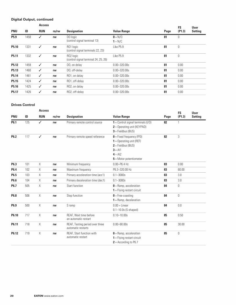
Digital Output, continued
Drives Control
PNU ID
Access
Designation Value Range Page FS(P1.3)
User SettingRUN ro/rw
P5.9 1458 rw DO logic(control signal terminal 13)
0 = N/O1 = N/C
81 0
P5.10 1331 rw RO1 logic(control signal terminals 22, 23)
Like P5.9 81 0
P5.11 1332 rw RO2 logic (control signal terminal 24, 25, 26)
Like P5.9 81 0
P5.12 1459 rw DO, on delay 0.00–320.00s 81 0.00
P5.13 1460 rw DO, off-delay 0.00–320.00s 81 0.00
P5.14 1461 rw RO1, on delay 0.00–320.00s 81 0.00
P5.15 1424 rw RO1, off-delay 0.00–320.00s 81 0.00
P5.16 1425 rw RO2, on delay 0.00–320.00s 81 0.00
P5.17 1426 rw RO2, off-delay 0.00–320.00s 81 0.00
PNU ID
Access
Designation Value Range Page FS(P1.3)
User SettingRUN ro/rw
P6.1 125 rw Primary remote control source 1 = Control signal terminals (I/O)2 = Operating unit (KEYPAD)3 = Fieldbus (BUS)
82 1
P6.2 117 rw Primary remote speed reference 0 = Fixed frequency (FF0)1 = Operating unit (REF)2 = Fieldbus (BUS)3 = AI14 = AI25 = Motor potentiometer
82 3
P6.3 101 X rw Minimum frequency 0.00–P6.4 Hz 83 0.00
P6.4 102 X rw Maximum frequency P6.3–320.00 Hz 83 60.00
P6.5 103 X rw Primary acceleration time (acc1) 0.1–3000s 83 3.0
P6.6 104 X rw Primary deceleration time (dec1) 0.1–3000s 83 3.0
P6.7 505 X rw Start function 0 = Ramp, acceleration1 = Flying restart circuit
84 0
P6.8 506 X rw Stop function 0 = Free coasting1 = Ramp, deceleration
84 0
P6.9 500 X rw S ramp 0.00 = Linear0.1–10.0s (S-shaped)
84 0.0
P6.10 717 X rw REAF, Wait time before an automatic restart
0.10–10.00s 85 0.50
P6.11 718 X rw REAF, Testing period over three automatic restarts
0.00–60.00s 85 30.00
P6.12 719 X rw REAF, Start function with automatic restart
0 = Ramp, acceleration1 = Flying restart circuit2 = According to P6.7
85 0
EATON www.eaton.com 21
Parameter Guide
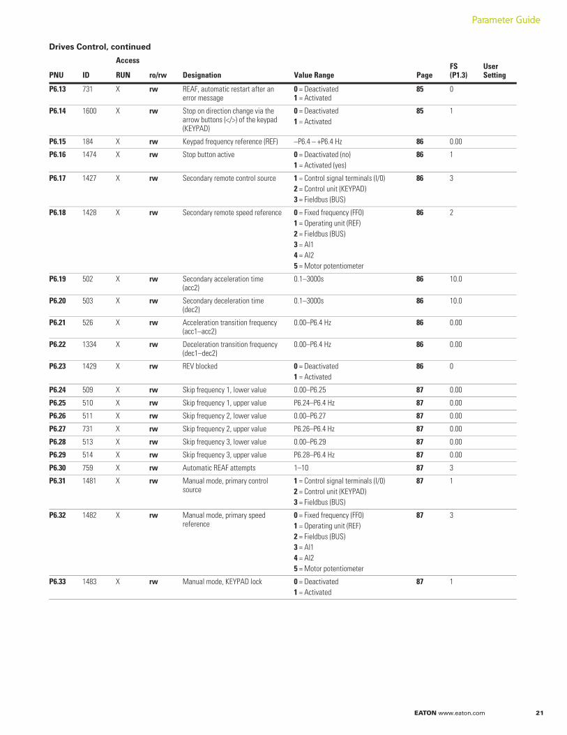
Drives Control, continued
PNU ID
Access
Designation Value Range Page FS(P1.3)
User SettingRUN ro/rw
P6.13 731 X rw REAF, automatic restart after an error message
0 = Deactivated1 = Activated
85 0
P6.14 1600 X rw Stop on direction change via the arrow buttons (</>) of the keypad (KEYPAD)
0 = Deactivated1 = Activated
85 1
P6.15 184 X rw Keypad frequency reference (REF) –P6.4 – +P6.4 Hz 86 0.00
P6.16 1474 X rw Stop button active 0 = Deactivated (no)1 = Activated (yes)
86 1
P6.17 1427 X rw Secondary remote control source 1 = Control signal terminals (I/0)2 = Control unit (KEYPAD)3 = Fieldbus (BUS)
86 3
P6.18 1428 X rw Secondary remote speed reference 0 = Fixed frequency (FF0)1 = Operating unit (REF)2 = Fieldbus (BUS)3 = AI14 = AI25 = Motor potentiometer
86 2
P6.19 502 X rw Secondary acceleration time (acc2)
0.1–3000s 86 10.0
P6.20 503 X rw Secondary deceleration time (dec2)
0.1–3000s 86 10.0
P6.21 526 X rw Acceleration transition frequency(acc1–acc2)
0.00–P6.4 Hz 86 0.00
P6.22 1334 X rw Deceleration transition frequency(dec1–dec2)
0.00–P6.4 Hz 86 0.00
P6.23 1429 X rw REV blocked 0 = Deactivated1 = Activated
86 0
P6.24 509 X rw Skip frequency 1, lower value 0.00–P6.25 87 0.00
P6.25 510 X rw Skip frequency 1, upper value P6.24–P6.4 Hz 87 0.00
P6.26 511 X rw Skip frequency 2, lower value 0.00–P6.27 87 0.00
P6.27 731 X rw Skip frequency 2, upper value P6.26–P6.4 Hz 87 0.00
P6.28 513 X rw Skip frequency 3, lower value 0.00–P6.29 87 0.00
P6.29 514 X rw Skip frequency 3, upper value P6.28–P6.4 Hz 87 0.00
P6.30 759 X rw Automatic REAF attempts 1–10 87 3
P6.31 1481 X rw Manual mode, primary control source
1 = Control signal terminals (I/0)2 = Control unit (KEYPAD)3 = Fieldbus (BUS)
87 1
P6.32 1482 X rw Manual mode, primary speedreference
0 = Fixed frequency (FF0)1 = Operating unit (REF)2 = Fieldbus (BUS)3 = AI14 = AI25 = Motor potentiometer
87 3
P6.33 1483 X rw Manual mode, KEYPAD lock 0 = Deactivated1 = Activated
87 1
22 EATON www.eaton.com
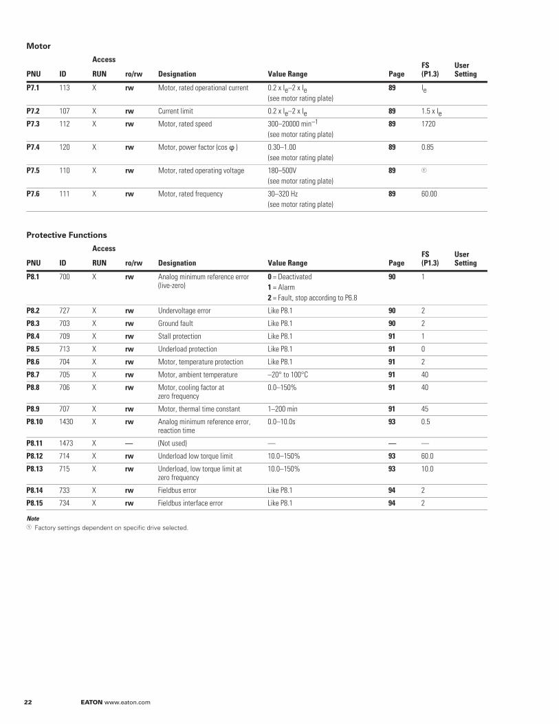
Motor
Protective Functions
NoteFactory settings dependent on specific drive selected.
PNU ID
Access
Designation Value Range Page FS(P1.3)
User SettingRUN ro/rw
P7.1 113 X rw Motor, rated operational current 0.2 x Ie–2 x Ie(see motor rating plate)
89 Ie
P7.2 107 X rw Current limit 0.2 x Ie–2 x Ie 89 1.5 x IeP7.3 112 X rw Motor, rated speed 300–20000 min–1
(see motor rating plate)89 1720
P7.4 120 X rw Motor, power factor (cos ) 0.30–1.00(see motor rating plate)
89 0.85
P7.5 110 X rw Motor, rated operating voltage 180–500V(see motor rating plate)
89
P7.6 111 X rw Motor, rated frequency 30–320 Hz(see motor rating plate)
89 60.00
PNU ID
Access
Designation Value Range Page FS(P1.3)
User SettingRUN ro/rw
P8.1 700 X rw Analog minimum reference error (live-zero)
0 = Deactivated1 = Alarm2 = Fault, stop according to P6.8
90 1
P8.2 727 X rw Undervoltage error Like P8.1 90 2
P8.3 703 X rw Ground fault Like P8.1 90 2
P8.4 709 X rw Stall protection Like P8.1 91 1
P8.5 713 X rw Underload protection Like P8.1 91 0
P8.6 704 X rw Motor, temperature protection Like P8.1 91 2
P8.7 705 X rw Motor, ambient temperature –20° to 100°C 91 40
P8.8 706 X rw Motor, cooling factor at zero frequency
0.0–150% 91 40
P8.9 707 X rw Motor, thermal time constant 1–200 min 91 45
P8.10 1430 X rw Analog minimum reference error, reaction time
0.0–10.0s 93 0.5
P8.11 1473 X — (Not used) — — —
P8.12 714 X rw Underload low torque limit 10.0–150% 93 60.0
P8.13 715 X rw Underload, low torque limit at zero frequency
10.0–150% 93 10.0
P8.14 733 X rw Fieldbus error Like P8.1 94 2
P8.15 734 X rw Fieldbus interface error Like P8.1 94 2
EATON www.eaton.com 23
Parameter Guide
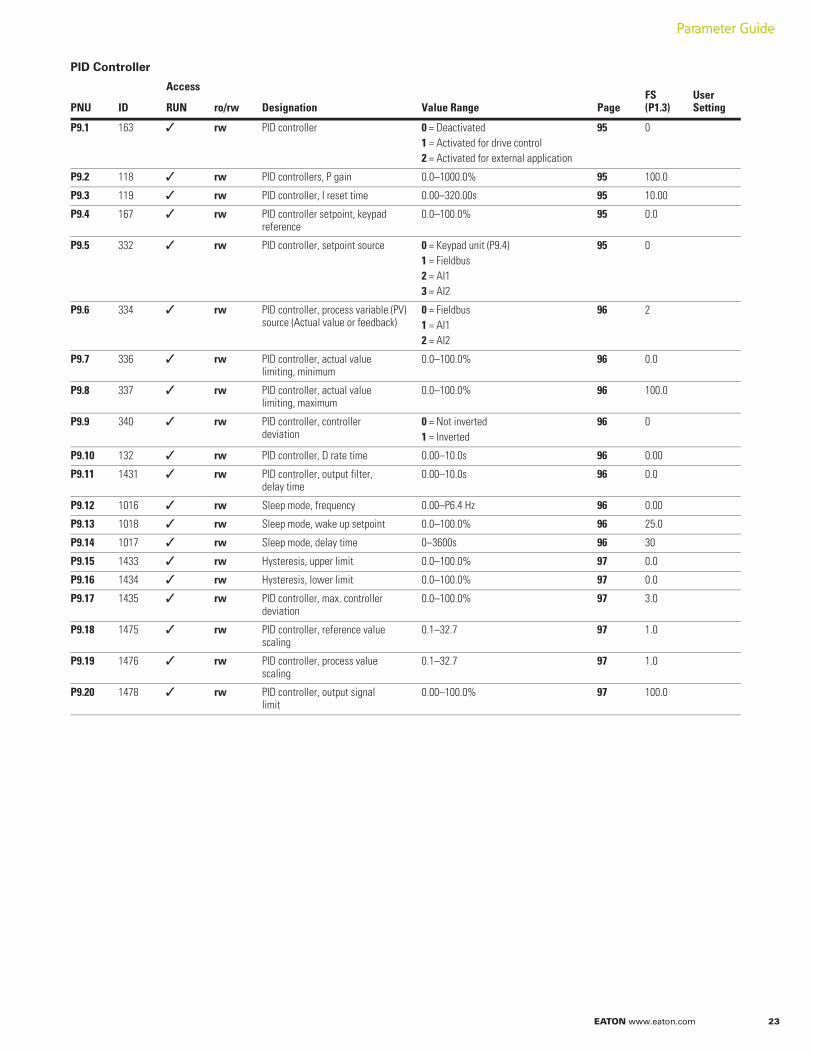
PID Controller
PNU ID
Access
Designation Value Range Page FS(P1.3)
User SettingRUN ro/rw
P9.1 163 rw PID controller 0 = Deactivated1 = Activated for drive control2 = Activated for external application
95 0
P9.2 118 rw PID controllers, P gain 0.0–1000.0% 95 100.0
P9.3 119 rw PID controller, I reset time 0.00–320.00s 95 10.00
P9.4 167 rw PID controller setpoint, keypad reference
0.0–100.0% 95 0.0
P9.5 332 rw PID controller, setpoint source 0 = Keypad unit (P9.4)1 = Fieldbus2 = AI13 = AI2
95 0
P9.6 334 rw PID controller, process variable (PV) source (Actual value or feedback)
0 = Fieldbus1 = AI12 = AI2
96 2
P9.7 336 rw PID controller, actual value limiting, minimum
0.0–100.0% 96 0.0
P9.8 337 rw PID controller, actual value limiting, maximum
0.0–100.0% 96 100.0
P9.9 340 rw PID controller, controller deviation
0 = Not inverted1 = Inverted
96 0
P9.10 132 rw PID controller, D rate time 0.00–10.0s 96 0.00
P9.11 1431 rw PID controller, output filter, delay time
0.00–10.0s 96 0.0
P9.12 1016 rw Sleep mode, frequency 0.00–P6.4 Hz 96 0.00
P9.13 1018 rw Sleep mode, wake up setpoint 0.0–100.0% 96 25.0
P9.14 1017 rw Sleep mode, delay time 0–3600s 96 30
P9.15 1433 rw Hysteresis, upper limit 0.0–100.0% 97 0.0
P9.16 1434 rw Hysteresis, lower limit 0.0–100.0% 97 0.0
P9.17 1435 rw PID controller, max. controllerdeviation
0.0–100.0% 97 3.0
P9.18 1475 rw PID controller, reference valuescaling
0.1–32.7 97 1.0
P9.19 1476 rw PID controller, process valuescaling
0.1–32.7 97 1.0
P9.20 1478 rw PID controller, output signal limit
0.00–100.0% 97 100.0
24 EATON www.eaton.com
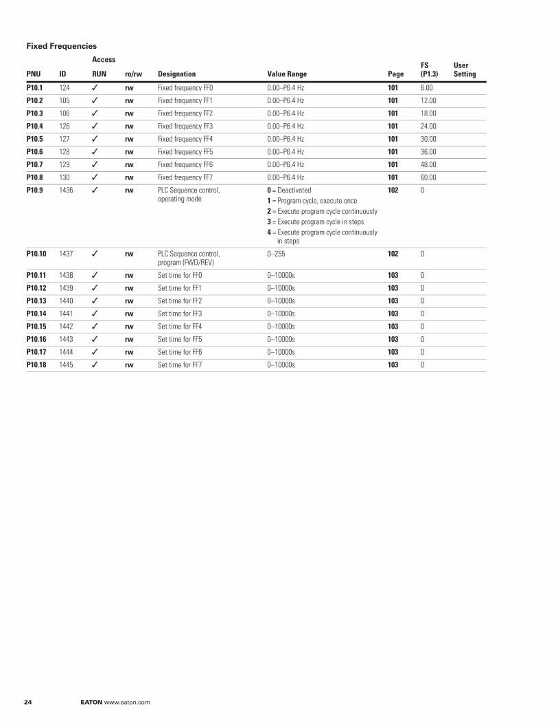
Fixed Frequencies
PNU ID
Access
Designation Value Range Page FS(P1.3)
User SettingRUN ro/rw
P10.1 124 rw Fixed frequency FF0 0.00–P6.4 Hz 101 6.00
P10.2 105 rw Fixed frequency FF1 0.00–P6.4 Hz 101 12.00
P10.3 106 rw Fixed frequency FF2 0.00–P6.4 Hz 101 18.00
P10.4 126 rw Fixed frequency FF3 0.00–P6.4 Hz 101 24.00
P10.5 127 rw Fixed frequency FF4 0.00–P6.4 Hz 101 30.00
P10.6 128 rw Fixed frequency FF5 0.00–P6.4 Hz 101 36.00
P10.7 129 rw Fixed frequency FF6 0.00–P6.4 Hz 101 48.00
P10.8 130 rw Fixed frequency FF7 0.00–P6.4 Hz 101 60.00
P10.9 1436 rw PLC Sequence control, operating mode
0 = Deactivated1 = Program cycle, execute once2 = Execute program cycle continuously3 = Execute program cycle in steps4 = Execute program cycle continuously
in steps
102 0
P10.10 1437 rw PLC Sequence control, program (FWD/REV)
0–255 102 0
P10.11 1438 rw Set time for FF0 0–10000s 103 0
P10.12 1439 rw Set time for FF1 0–10000s 103 0
P10.13 1440 rw Set time for FF2 0–10000s 103 0
P10.14 1441 rw Set time for FF3 0–10000s 103 0
P10.15 1442 rw Set time for FF4 0–10000s 103 0
P10.16 1443 rw Set time for FF5 0–10000s 103 0
P10.17 1444 rw Set time for FF6 0–10000s 103 0
P10.18 1445 rw Set time for FF7 0–10000s 103 0
EATON www.eaton.com 25
Parameter Guide
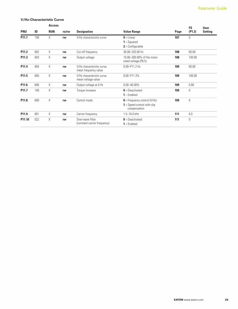
V/Hz-Characteristic Curve
PNU ID
Access
Designation Value Range Page FS(P1.3)
User SettingRUN ro/rw
P11.1 108 X rw V/Hz characteristic curve 0 = Linear1 = Squared2 = Configurable
107 0
P11.2 602 X rw Cut-off frequency 30.00–320.00 Hz 108 60.00
P11.3 603 X rw Output voltage 10.00–200.00% of the motor rated voltage (P6.5)
108 100.00
P11.4 604 X rw V/Hz characteristic curve, mean frequency value
0.00–P11.2 Hz 109 60.00
P11.5 605 X rw V/Hz characteristic curve, mean voltage value
0.00–P11.3% 109 100.00
P11.6 606 X rw Output voltage at 0 Hz 0.00–40.00% 109 0.00
P11.7 109 X rw Torque increase 0 = Deactivated1 = Enabled
109 0
P11.8 600 X rw Control mode 0 = Frequency control (V/Hz)1 = Speed control with slip
compensation
109 0
P11.9 601 X rw Carrier frequency 1.5–16.0 kHz 111 6.0
P11.10 522 X rw Sine-wave filter (constant carrier frequency)
0 = Deactivated1 = Enabled
111 0
26 EATON www.eaton.com
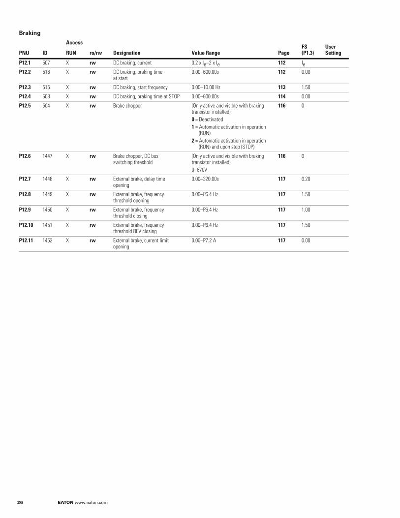
Braking
PNU ID
Access
Designation Value Range Page FS(P1.3)
User SettingRUN ro/rw
P12.1 507 X rw DC braking, current 0.2 x Ie–2 x Ie 112 IeP12.2 516 X rw DC braking, braking time
at start0.00–600.00s 112 0.00
P12.3 515 X rw DC braking, start frequency 0.00–10.00 Hz 113 1.50
P12.4 508 X rw DC braking, braking time at STOP 0.00–600.00s 114 0.00
P12.5 504 X rw Brake chopper (Only active and visible with braking transistor installed)0 = Deactivated1 = Automatic activation in operation
(RUN)2 = Automatic activation in operation
(RUN) and upon stop (STOP)
116 0
P12.6 1447 X rw Brake chopper, DC busswitching threshold
(Only active and visible with braking transistor installed)0–870V
116 0
P12.7 1448 X rw External brake, delay time opening
0.00–320.00s 117 0.20
P12.8 1449 X rw External brake, frequency threshold opening
0.00–P6.4 Hz 117 1.50
P12.9 1450 X rw External brake, frequency threshold closing
0.00–P6.4 Hz 117 1.00
P12.10 1451 X rw External brake, frequency threshold REV closing
0.00–P6.4 Hz 117 1.50
P12.11 1452 X rw External brake, current limit opening
0.00–P7.2 A 117 0.00
EATON www.eaton.com 27
Parameter Guide
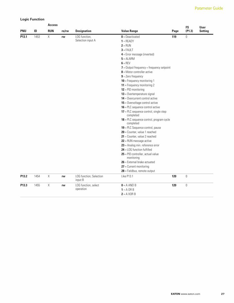
Logic Function
PNU ID
Access
Designation Value Range Page FS(P1.3)
User SettingRUN ro/rw
P13.1 1453 X rw LOG function, Selection input A
0 = Deactivated1 = READY2 = RUN3 = FAULT4 = Error message (inverted)5 = ALARM6 = REV7 = Output frequency = frequency setpoint8 = Motor controller active9 = Zero frequency10 = Frequency monitoring 111 = Frequency monitoring 212 = PID monitoring13 = Overtemperature signal14 = Overcurrent control active15 = Overvoltage control active16 = PLC sequence control active17 = PLC sequence control, single step
completed18 = PLC sequence control, program cycle
completed19 = PLC Sequence control, pause20 = Counter, value 1 reached21 = Counter, value 2 reached22 = RUN message active23 = Analog min. reference error24 = LOG function fulfilled25 = PID controller, actual value
monitoring26 = External brake actuated27 = Current monitoring28 = Fieldbus, remote output
119 0
P13.2 1454 X rw LOG function, Selection input B
Like P13.1 120 0
P13.3 1455 X rw LOG function, select operation
0 = A AND B1 = A OR B2 = A XOR B
120 0
28 EATON www.eaton.com
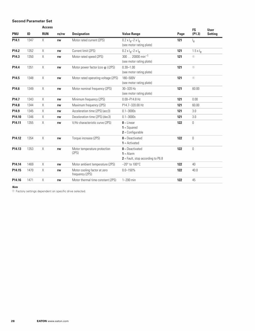
Second Parameter Set
NoteFactory settings dependent on specific drive selected.
PNU ID
Access
Designation Value Range Page FS(P1.3)
User SettingRUN ro/rw
P14.1 1347 X rw Motor rated current (2PS) 0.2 x Ie–2 x Ie(see motor rating plate)
121 Ie
P14.2 1352 X rw Current limit (2PS) 0.2 x Ie–2 x Ie 121 1.5 x IeP14.3 1350 X rw Motor rated speed (2PS) 300 … 20000 min–1
(see motor rating plate)121
P14.4 1351 X rw Motor power factor (cos ) (2PS) 0.30–1.00(see motor rating plate)
121
P14.5 1348 X rw Motor rated operating voltage (2PS) 180–500V(see motor rating plate)
121
P14.6 1349 X rw Motor nominal frequency (2PS) 30–320 Hz(see motor rating plate)
121 60.00
P14.7 1343 X rw Minimum frequency (2PS) 0.00–P14.8 Hz 121 0.00
P14.8 1344 X rw Maximum frequency (2PS) P14.7–320.00 Hz 121 60.00
P14.9 1345 X rw Acceleration time (2PS) (acc3) 0.1–3000s 121 3.0
P14.10 1346 X rw Deceleration time (2PS) (dec3) 0.1–3000s 121 3.0
P14.11 1355 X rw V/Hz characteristic curve (2PS) 0 = Linear1 = Squared2 = Configurable
122 0
P14.12 1354 X rw Torque increase (2PS) 0 = Deactivated1 = Activated
122 0
P14.13 1353 X rw Motor temperature protection (2PS)
0 = Deactivated1 = Alarm2 = Fault, stop according to P6.8
122 0
P14.14 1469 X rw Motor ambient temperature (2PS) –20° to 100°C 122 40
P14.15 1470 X rw Motor cooling factor at zero frequency (2PS)
0.0–150% 122 40.0
P14.16 1471 X rw Motor thermal time constant (2PS) 1–200 min 122 45
EATON www.eaton.com 29
Parameter Guide
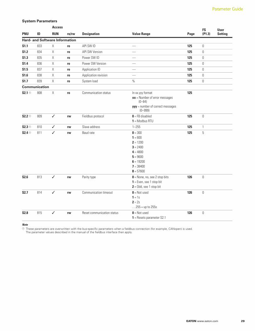
System Parameters
NoteThese parameters are overwritten with the bus-specific parameters when a fieldbus connection (for example, CANopen) is used. The parameter values described in the manual of the fieldbus interface then apply.
PNU ID
Access
Designation Value Range Page FS(P1.3)
User SettingRUN ro/rw
Hard- and Software Information
S1.1 833 X ro API SW ID — 125 0
S1.2 834 X ro API SW Version — 125 0
S1.3 835 X ro Power SW ID — 125 0
S1.4 836 X ro Power SW Version — 125 0
S1.5 837 X ro Application ID — 125 0
S1.6 838 X ro Application revision — 125 0
S1.7 839 X ro System load % 125 0
Communication
S2.1 808 X ro Communication status In xx.yyy formatxx = Number of error messages
(0–64)yyy = number of correct messages
(0–999)
125
S2.2 809 rw Fieldbus protocol 0 = FB disabled1 = Modbus RTU
125 0
S2.3 810 rw Slave address 1–255 125 1
S2.4 811 rw Baud rate 0 = 3001 = 6002 = 12003 = 24004 = 48005 = 96006 = 192007 = 384008 = 57600
125 5
S2.6 813 rw Parity type 0 = None, no, see 2 stop bits1 = Even, see 1 stop bit2 = Odd, see 1 stop bit
126 0
S2.7 814 rw Communication timeout 0 = Not used1 = 1s2 = 2s…255 = up to 255s
126 0
S2.8 815 rw Reset communication status 0 = Not used1 = Resets parameter S2.1
126 0
30 EATON www.eaton.com
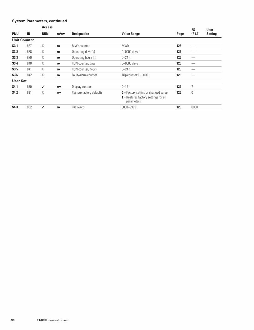
System Parameters, continued
PNU ID
Access
Designation Value Range Page FS(P1.3)
User SettingRUN ro/rw
Unit Counter
S3.1 827 X ro MWh counter MWh 126 —
S3.2 828 X ro Operating days (d) 0–0000 days 126 —
S3.3 829 X ro Operating hours (h) 0–24 h 126 —
S3.4 840 X ro RUN counter, days 0–0000 days 126 —
S3.5 841 X ro RUN counter, hours 0–24 h 126 —
S3.6 842 X ro Fault/alarm counter Trip counter: 0–0000 126 —
User Set
S4.1 830 rw Display contrast 0–15 126 7
S4.2 831 X rw Restore factory defaults 0 = Factory setting or changed value1 = Restores factory settings for all
parameters
126 0
S4.3 832 ro Password 0000–9999 126 0000
EATON www.eaton.com 31
Parameter Guide
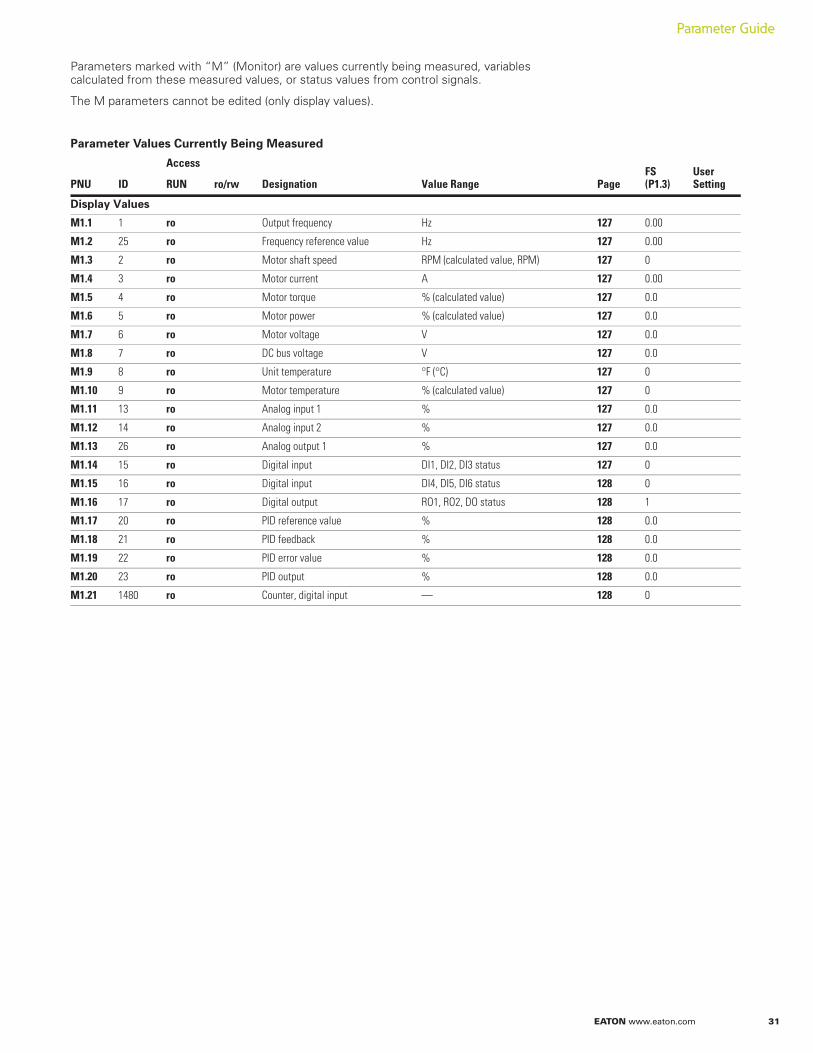
Parameters marked with “M” (Monitor) are values currently being measured, variables calculated from these measured values, or status values from control signals.
The M parameters cannot be edited (only display values).
Parameter Values Currently Being Measured
PNU ID
Access
Designation Value Range Page FS(P1.3)
User SettingRUN ro/rw
Display Values
M1.1 1 ro Output frequency Hz 127 0.00
M1.2 25 ro Frequency reference value Hz 127 0.00
M1.3 2 ro Motor shaft speed RPM (calculated value, RPM) 127 0
M1.4 3 ro Motor current A 127 0.00
M1.5 4 ro Motor torque % (calculated value) 127 0.0
M1.6 5 ro Motor power % (calculated value) 127 0.0
M1.7 6 ro Motor voltage V 127 0.0
M1.8 7 ro DC bus voltage V 127 0.0
M1.9 8 ro Unit temperature °F (°C) 127 0
M1.10 9 ro Motor temperature % (calculated value) 127 0
M1.11 13 ro Analog input 1 % 127 0.0
M1.12 14 ro Analog input 2 % 127 0.0
M1.13 26 ro Analog output 1 % 127 0.0
M1.14 15 ro Digital input DI1, DI2, DI3 status 127 0
M1.15 16 ro Digital input DI4, DI5, DI6 status 128 0
M1.16 17 ro Digital output RO1, RO2, DO status 128 1
M1.17 20 ro PID reference value % 128 0.0
M1.18 21 ro PID feedback % 128 0.0
M1.19 22 ro PID error value % 128 0.0
M1.20 23 ro PID output % 128 0.0
M1.21 1480 ro Counter, digital input — 128 0

De
fault P
aram
ete
r Se
t
EATON www.eaton.com 32
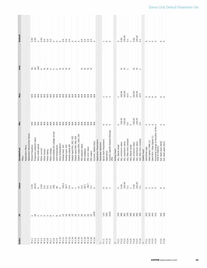
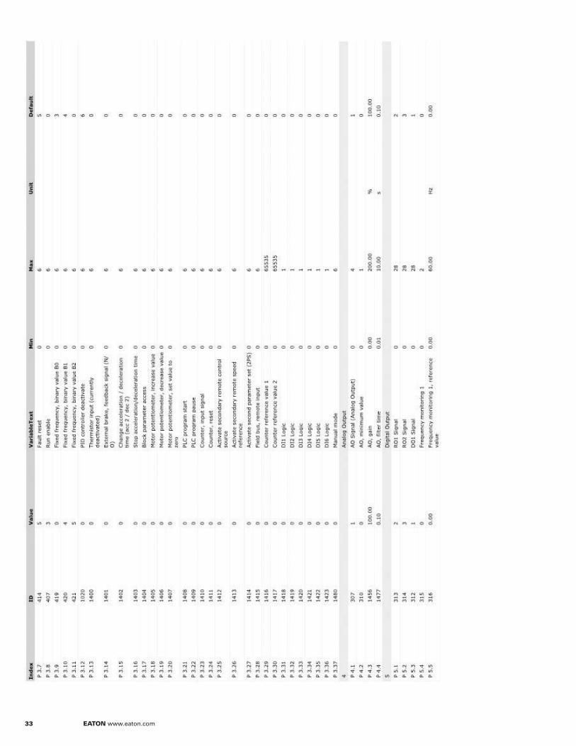
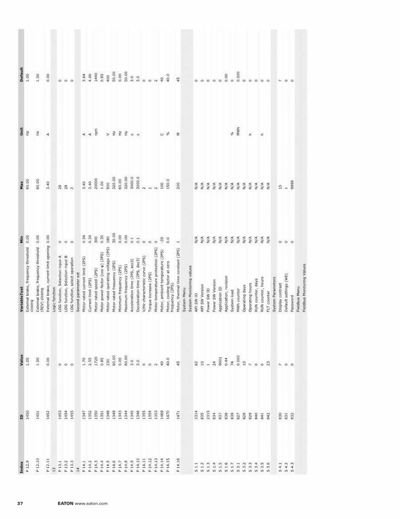
Demo Unit Default Parameter Set
33 EATON www.eaton.com
EATON www.eaton.com 34
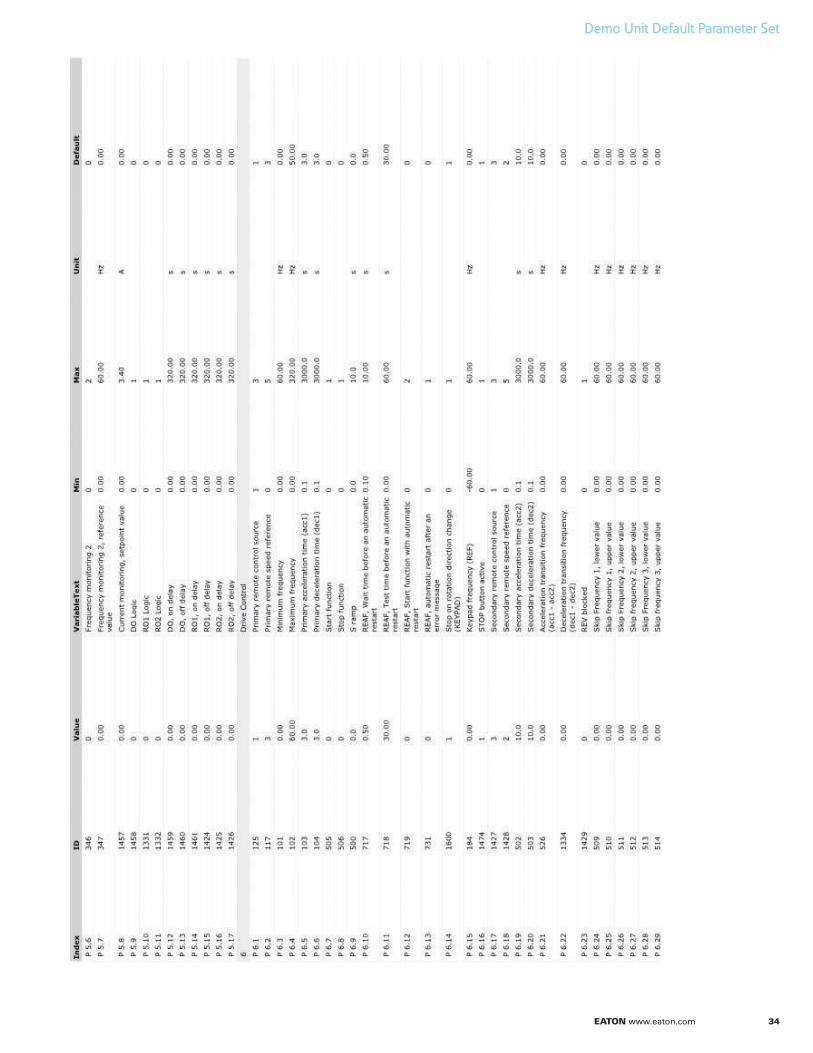
Demo Unit Default Parameter Set
35 EATON www.eaton.com
EATON www.eaton.com 36
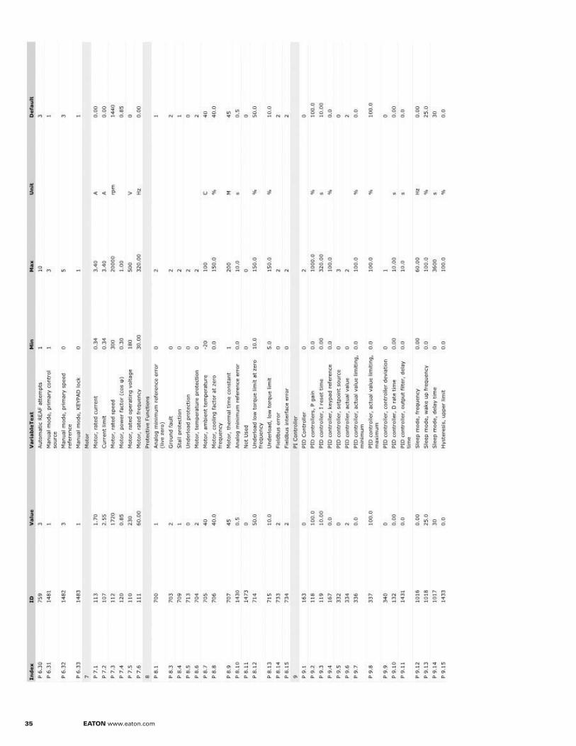
Demo Unit Default Parameter Set
37 EATON www.eaton.com
EATON www.eaton.com 38
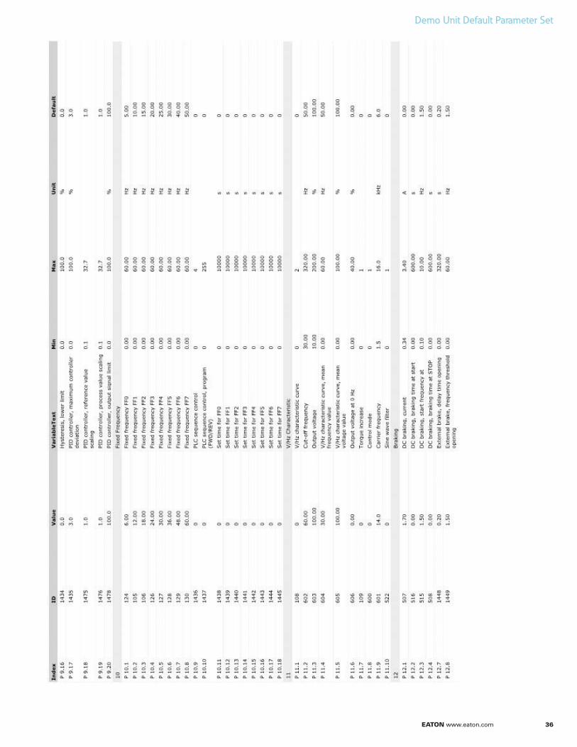
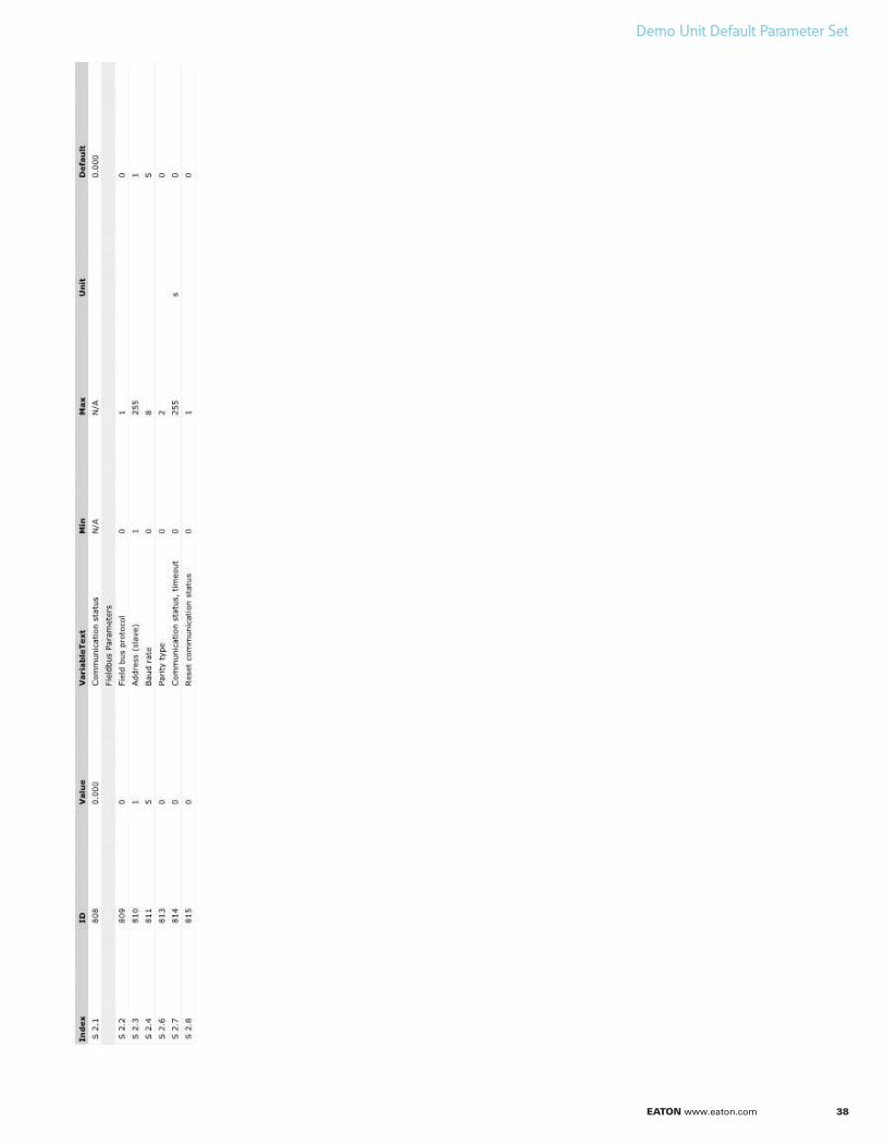
Demo Unit Default Parameter Set

De
mo
Ove
rvie
w
EATON www.eaton.com 39
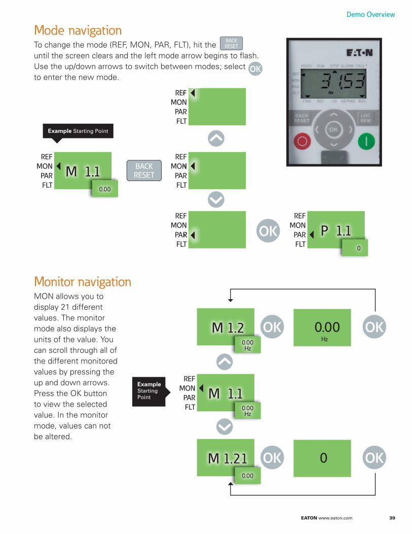
Mode navigationTo change the mode (REF, MON, PAR, FLT), hit the until the screen clears and the left mode arrow begins to flash.Use the up/down arrows to switch between modes; select to enter the new mode.
BACKRESET
OK
Demo Overview
Monitor navigationMON allows you to display 21 different values. The monitor mode also displays the units of the value. You can scroll through all of the different monitored values by pressing the up and down arrows. Press the OK button to view the selected value. In the monitor mode, values can not be altered.
REF
MON
PAR
FLT
M 1.10.00
REF
MON
PAR
FLT
P 1.1 0
REF
MON
PAR
FLT
REF
MON
PAR
FLT
REF
MON
PAR
FLT
BACKRESET
OK
Example Starting Point
M 1.1
REF
MON
PAR
FLT
0M 1.21 OK OK
0.00Hz
0.00Hz
M 1.2 OK OK0.00Hz
Example Starting Point
0.00
40 EATON www.eaton.com
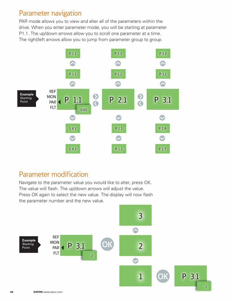
Parameter navigationPAR mode allows you to view and alter all of the parameters within the drive. When you enter parameter mode, you will be starting at parameter P1.1. The up/down arrows allow you to scroll one parameter at a time. The right/left arrows allow you to jump from parameter group to group.
Parameter modificationNavigate to the parameter value you would like to alter, press OK. The value will flash. The up/down arrows will adjust the value. Press OK again to select the new value. The display will now flash the parameter number and the new value.
P 1.1 P 2.1 P 3.10.00
P 1.2 P 2.2 P 3.2
S 4.2 P 2.7P 1.2
P 1.3 P 2.3 P 3.3
S 4.3 P 2.8P 1.3
REF
MON
PAR
FLT
P 3.1 1
P 3.1 2
2
3
1
OK
OK
Example Starting Point
Example Starting Point
REF
MON
PAR
FLT
EATON www.eaton.com 41
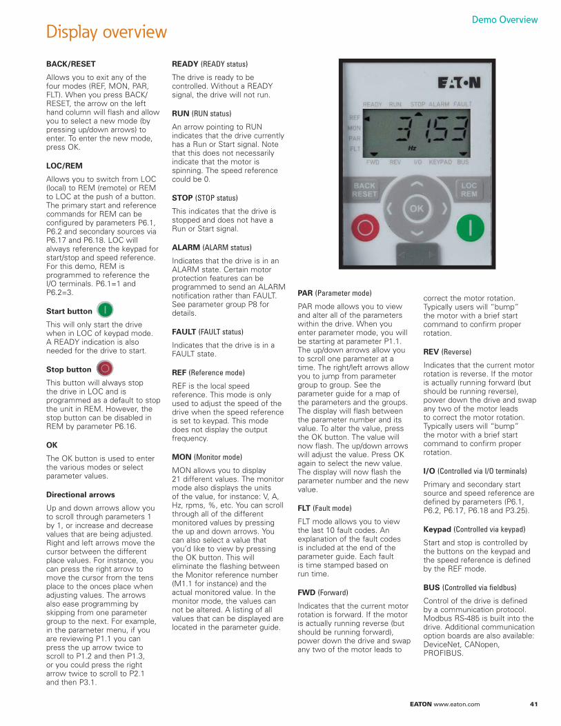
BACK/RESET
Allows you to exit any of the four modes (REF, MON, PAR, FLT). When you press BACK/RESET, the arrow on the left hand column will flash and allow you to select a new mode (by pressing up/down arrows) to enter. To enter the new mode, press OK.
LOC/REM
Allows you to switch from LOC (local) to REM (remote) or REM to LOC at the push of a button. The primary start and reference commands for REM can be configured by parameters P6.1, P6.2 and secondary sources via P6.17 and P6.18. LOC will always reference the keypad for start/stop and speed reference. For this demo, REM is programmed to reference the I/O terminals. P6.1=1 and P6.2=3.
Start button
This will only start the drive when in LOC of keypad mode. A READY indication is also needed for the drive to start.
Stop button
This button will always stop the drive in LOC and is programmed as a default to stop the unit in REM. However, the stop button can be disabled in REM by parameter P6.16.
OK
The OK button is used to enter the various modes or select parameter values.
Directional arrows
Up and down arrows allow you to scroll through parameters 1 by 1, or increase and decrease values that are being adjusted. Right and left arrows move the cursor between the different place values. For instance, you can press the right arrow to move the cursor from the tens place to the onces place when adjusting values. The arrows also ease programming by skipping from one parameter group to the next. For example, in the parameter menu, if you are reviewing P1.1 you can press the up arrow twice to scroll to P1.2 and then P1.3, or you could press the right arrow twice to scroll to P2.1 and then P3.1.
READY (READY status)
The drive is ready to be controlled. Without a READY signal, the drive will not run.
RUN (RUN status)
An arrow pointing to RUN indicates that the drive currently has a Run or Start signal. Note that this does not necessarily indicate that the motor is spinning. The speed reference could be 0.
STOP (STOP status)
This indicates that the drive is stopped and does not have a Run or Start signal.
ALARM (ALARM status)
Indicates that the drive is in an ALARM state. Certain motor protection features can be programmed to send an ALARM notification rather than FAULT. See parameter group P8 for details.
FAULT (FAULT status)
Indicates that the drive is in a FAULT state.
REF (Reference mode)
REF is the local speed reference. This mode is only used to adjust the speed of the drive when the speed reference is set to keypad. This mode does not display the output frequency.
MON (Monitor mode)
MON allows you to display 21 different values. The monitor mode also displays the units of the value, for instance: V, A, Hz, rpms, %, etc. You can scroll through all of the different monitored values by pressing the up and down arrows. You can also select a value that you’d like to view by pressing the OK button. This will eliminate the flashing between the Monitor reference number (M1.1 for instance) and the actual monitored value. In the monitor mode, the values can not be altered. A listing of all values that can be displayed are located in the parameter guide.
PAR (Parameter mode)
PAR mode allows you to view and alter all of the parameters within the drive. When you enter parameter mode, you will be starting at parameter P1.1. The up/down arrows allow you to scroll one parameter at a time. The right/left arrows allow you to jump from parameter group to group. See the parameter guide for a map of the parameters and the groups. The display will flash between the parameter number and its value. To alter the value, press the OK button. The value will now flash. The up/down arrows will adjust the value. Press OK again to select the new value. The display will now flash the parameter number and the new value.
FLT (Fault mode)
FLT mode allows you to view the last 10 fault codes. An explanation of the fault codes is included at the end of the parameter guide. Each fault is time stamped based on run time.
FWD (Forward)
Indicates that the current motor rotation is forward. If the motor is actually running reverse (but should be running forward), power down the drive and swap any two of the motor leads to
correct the motor rotation. Typically users will “bump” the motor with a brief start command to confirm proper rotation.
REV (Reverse)
Indicates that the current motor rotation is reverse. If the motor is actually running forward (but should be running reverse), power down the drive and swap any two of the motor leads to correct the motor rotation. Typically users will “bump” the motor with a brief start command to confirm proper rotation.
I/O (Controlled via I/O terminals)
Primary and secondary start source and speed reference are defined by parameters (P6.1, P6.2, P6.17, P6.18 and P3.25).
Keypad (Controlled via keypad)
Start and stop is controlled by the buttons on the keypad and the speed reference is defined by the REF mode.
BUS (Controlled via fieldbus)
Control of the drive is defined by a communication protocol. Modbus RS-485 is built into the drive. Additional communication option boards are also available: DeviceNet, CANopen, PROFIBUS.
Display overviewDemo Overview
42 EATON www.eaton.com
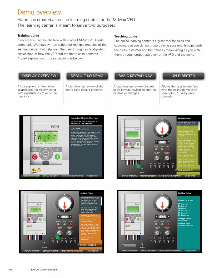
Demo overviewEaton has created an online learning center for the M-Max VFD. The learning center is meant to serve two purposes:
DISPLAY OVERVIEW DEFAULT I/O DEMO UN-DIRECTEDBASIC KEYPAD NAV
A closeup look at the drives keypad and the display along with explanations of all of the functions.
A step-by-step review of the demo case default program.
A step-by-step review of some basic keypad navigation and the parameter changes.
Allows the user to interface with the online demo in an unscripted, “trial by error” scenario.
Training guide It allows the user to interface with a virtual M-Max VFD and a demo unit. We have written scripts for multiple modules of the learning center that help walk the user through a step-by-step explanation of how the VFD and the demo case operates. A brief explanation of those sections is below.
Teaching guide The online learning center is a great tool for sales and customers to use during group training sessions. It helps both the class instructor and the trainees follow along as you walk them through proper operation of the VFD and the demo.
Eaton
1000 Eaton BoulevardCleveland, OH 44122United StatesEaton.com
© 2013 EatonAll Rights ReservedPrinted in USAPublication No. TR04002001E / Z14227September 2013
Eaton is a registered trademark.
All other trademarks are property of their respective owners.