Embed Size (px)
Citation preview
The NGN Carrier Ethernet System: Technologies, Architecture and Deployment Models
Biren Mehta
Sr. Marketing Manager
Agenda
Market Trends and its Impact on Network Infrastructure
Cisco Carrier Ethernet Transport Architecture
Cisco Carrier Ethernet Portfolio
TCO Leadership
Closing Remarks
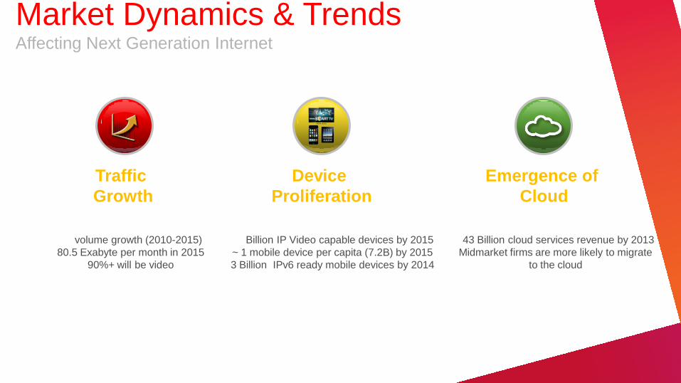
Device
Proliferation
Traffic
Growth
Emergence of
Cloud
$43 Billion cloud services revenue by 2013
Midmarket firms are more likely to migrate
to the cloud
12 Billion IP Video capable devices by 2015
~ 1 mobile device per capita (7.2B) by 2015
3 Billion IPv6 ready mobile devices by 2014
4X volume growth (2010-2015)
80.5 Exabyte per month in 2015
90%+ will be video
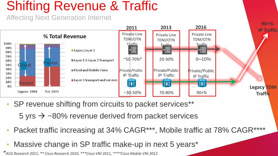
Market Dynamics & Trends Affecting Next Generation Internet
Packet
Circuit Packet
90+% IP Traffic
Private Line TDM/OTN
Traffic
Private/Public IP Traffic
2011
~30-50%
~50-70%*
2013 2016
Private Line TDM/OTN
Traffic
Private Line TDM/OTN
Traffic
20-30% 0─10%
Private/Public IP Traffic
Private/Public
IP Traffic
70-80% 90+% Legacy TDM
Traffic
*ACG Research 2011, ** Cisco Research 2010, ***Cisco VNI 2011, ****Cisco Mobile VNI 2012
• SP revenue shifting from circuits to packet services**
5 yrs ~80% revenue derived from packet services
• Packet traffic increasing at 34% CAGR***, Mobile traffic at 78% CAGR****
• Massive change in SP traffic make-up in next 5 years*
Shifting Revenue & Traffic Affecting Next Generation Internet
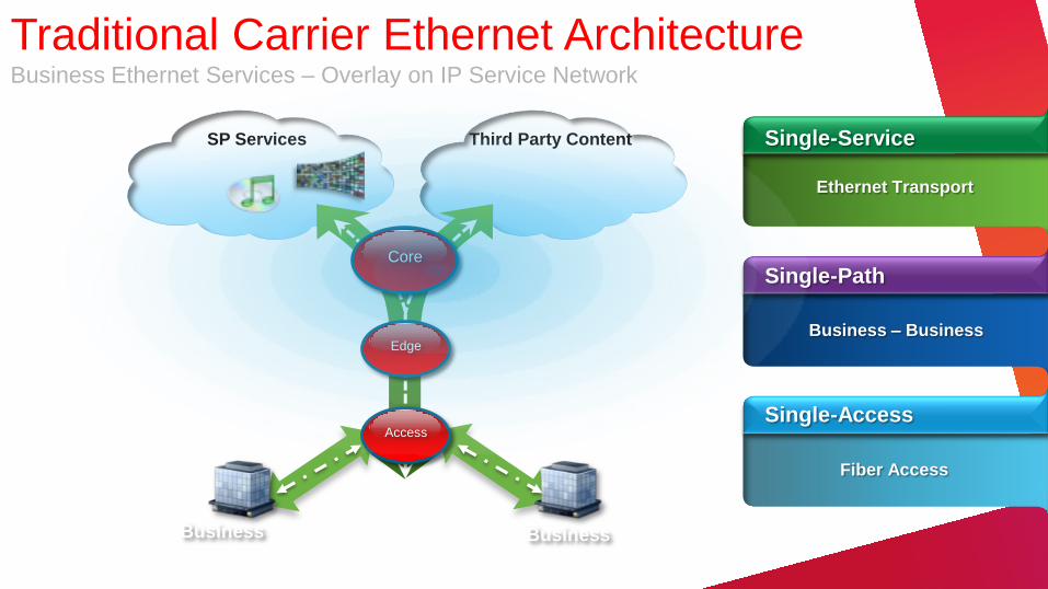
SP Services Third Party Content
Traditional Carrier Ethernet Architecture Business Ethernet Services – Overlay on IP Service Network
Core
Access
Single-Service
Single-Path
Single-Access
Ethernet Transport
Business – Business
Fiber Access
Edge
Business Business
National Data Center/ Cloud/VHO
National Data Center/ Cloud/VHO
Regional Data
Center/VSO
Regional Data
Center/VSO
SP Content
Third-Party Content
Business
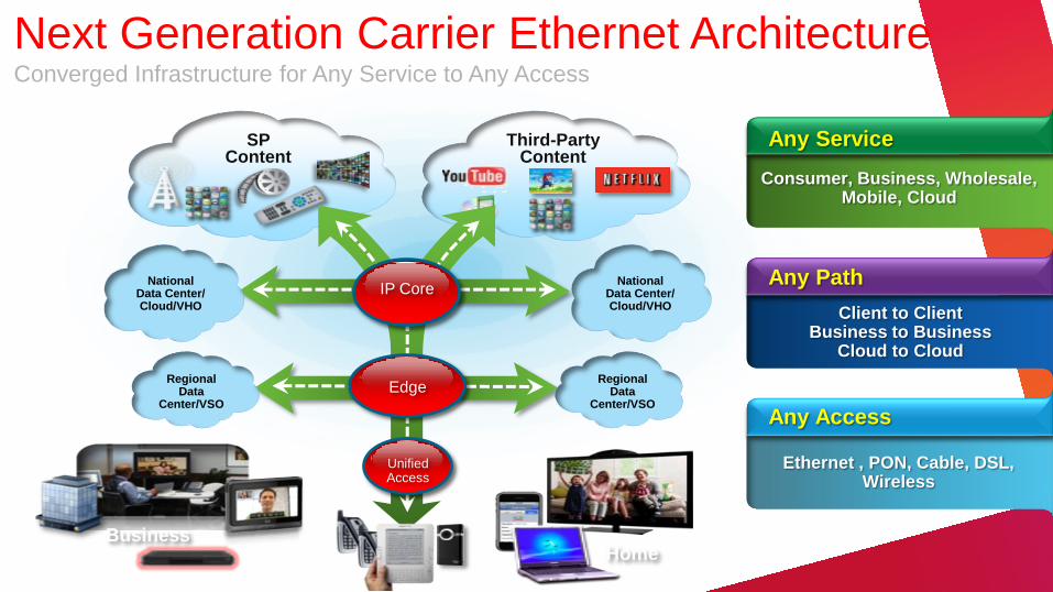
Next Generation Carrier Ethernet Architecture Converged Infrastructure for Any Service to Any Access
IP Core
Edge
Unified Access
Home
Any Service
Any Path
Any Access
Consumer, Business, Wholesale, Mobile, Cloud
Client to Client Business to Business
Cloud to Cloud
Ethernet , PON, Cable, DSL, Wireless
Multi-point
SP Services/ Content
Third-Party Services/ Content
National Data Center/ Cloud/VHO
National Data Center/ Cloud/VHO
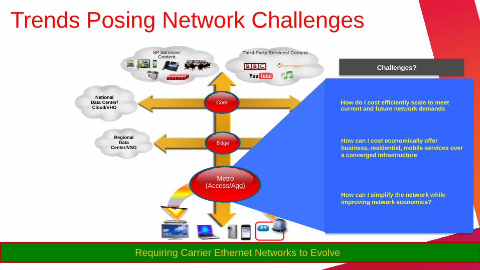
Trends Posing Network Challenges
Regional Data
Center/VSO
Regional Data Center/VSO Edge
Core
The Challenges?
Business
Requiring Carrier Ethernet Networks to Evolve
Increasing Complexity
Rising Costs
Limited Flexibility
How can I cost economically offer
business, residential, mobile services over
a converged infrastructure
How do I cost efficiently scale to meet current and future network demands
How can I simplify the network while
improving network economics?
Metro (Access/Agg)
Challenges?
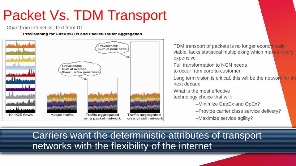
Packet Vs. TDM Transport
TDM transport of packets is no longer economically
viable, lacks statistical multiplexing which makes it very
expensive
Full transformation to NGN needs
to occur from core to customer
Long term vision is critical, this will be the network for the
next decade
What is the most effective
technology choice that will:
–Minimize CapEx and OpEx?
–Provide carrier class service delivery?
–Maximize service agility?
Carriers want the deterministic attributes of transport networks with the flexibility of the internet
Chart from Infonetics, Text from DT
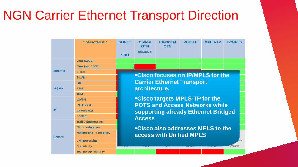
NGN Carrier Ethernet Transport Direction
Characteristic SONET
/
SDH
Optical OTN
(ROADMs)
Electrical OTN
PBB-TE MPLS-TP IP/MPLS
Ethernet
Eline (10GE)
Eline (sub 10GE)
E-Tree
E-LAN
Legacy
F/R
ATM
TDM
IP
L3VPN
L3 Unicast
L3 Multicast
Content
General
Traffic Engineering
50ms restoration
Multiplexing Technology Time Division
Wave Division Time Division Statistical Statistical Statistical
UNI processing Limited None None Typically rich Typically rich Typically rich
Granularity VC-4 Lambda ODU Variable Variable Variable
Technology Maturity
Cisco focuses on IP/MPLS for the Carrier Ethernet Transport architecture.
Cisco targets MPLS-TP for the POTS and Access Networks while supporting already Ethernet Bridged Access
Cisco also addresses MPLS to the access with Unified MPLS
L2 – Transport Technology Review
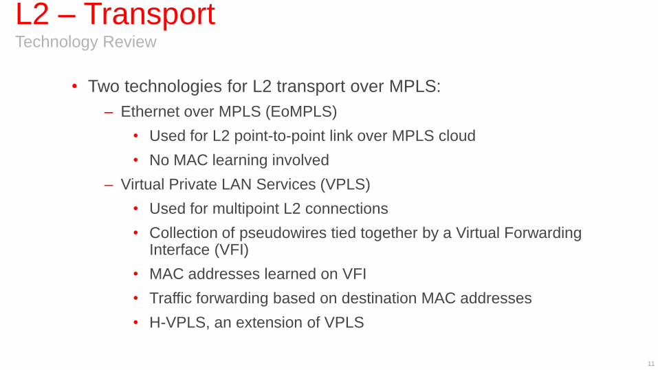
• Two technologies for L2 transport over MPLS:
– Ethernet over MPLS (EoMPLS)
• Used for L2 point-to-point link over MPLS cloud
• No MAC learning involved
– Virtual Private LAN Services (VPLS)
• Used for multipoint L2 connections
• Collection of pseudowires tied together by a Virtual Forwarding Interface (VFI)
• MAC addresses learned on VFI
• Traffic forwarding based on destination MAC addresses
• H-VPLS, an extension of VPLS
11
MPLS
EoMPLS Technology Review
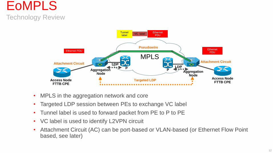
• MPLS in the aggregation network and core
• Targeted LDP session between PEs to exchange VC label
• Tunnel label is used to forward packet from PE to P to PE
• VC label is used to identify L2VPN circuit
• Attachment Circuit (AC) can be port-based or VLAN-based (or Ethernet Flow Point based, see later)
12
Pseudowire
Aggregation Node
P Aggregation
Node
Access Node FTTB CPE
Access Node FTTB CPE
LDP LDP
Targeted LDP
Attachment Circuit Attachment Circuit
P
Tunnel label
Ethernet PDU
VC label
Ethernet PDU Ethernet
PDU
VPLS Technology Review
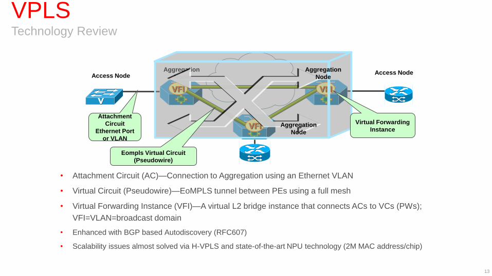
• Attachment Circuit (AC)—Connection to Aggregation using an Ethernet VLAN
• Virtual Circuit (Pseudowire)—EoMPLS tunnel between PEs using a full mesh
• Virtual Forwarding Instance (VFI)—A virtual L2 bridge instance that connects ACs to VCs (PWs);
VFI=VLAN=broadcast domain
• Enhanced with BGP based Autodiscovery (RFC607)
• Scalability issues almost solved via H-VPLS and state-of-the-art NPU technology (2M MAC address/chip)
13
Aggregation
Node
MPLS
Core
VFI
VFI
VFI
Attachment
Circuit
Ethernet Port
or VLAN
Virtual Forwarding
Instance
Eompls Virtual Circuit
(Pseudowire)
Aggregation
Node
Aggregation
Node
Access Node Access Node
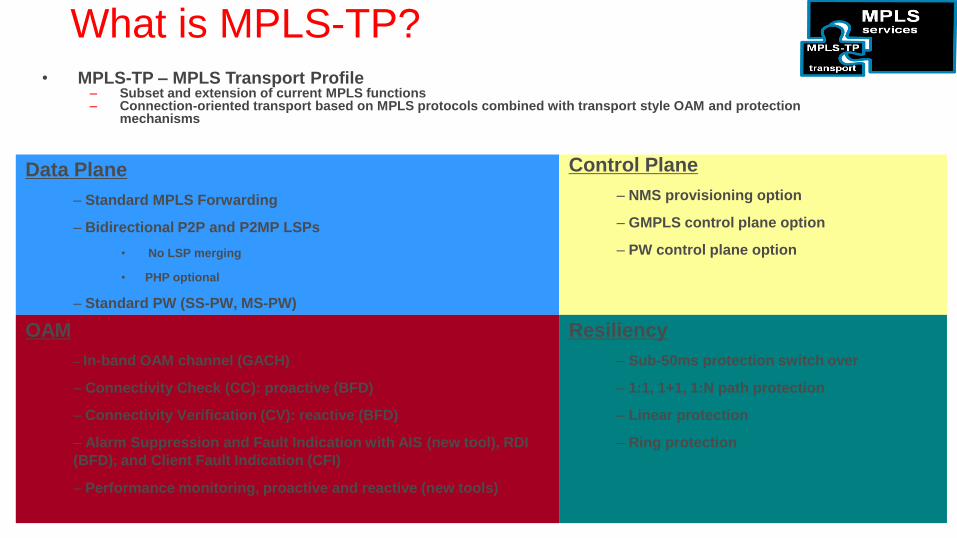
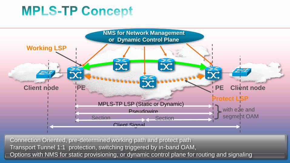
What is MPLS-TP? • MPLS-TP – MPLS Transport Profile
– Subset and extension of current MPLS functions – Connection-oriented transport based on MPLS protocols combined with transport style OAM and protection
mechanisms
Data Plane
– Standard MPLS Forwarding
– Bidirectional P2P and P2MP LSPs
• No LSP merging
• PHP optional
– Standard PW (SS-PW, MS-PW)
Control Plane
– NMS provisioning option
– GMPLS control plane option
– PW control plane option
OAM
– In-band OAM channel (GACH)
– Connectivity Check (CC): proactive (BFD)
– Connectivity Verification (CV): reactive (BFD)
– Alarm Suppression and Fault Indication with AIS (new tool), RDI
(BFD), and Client Fault Indication (CFI)
– Performance monitoring, proactive and reactive (new tools)
Resiliency
– Sub-50ms protection switch over
– 1:1, 1+1, 1:N path protection
– Linear protection
– Ring protection
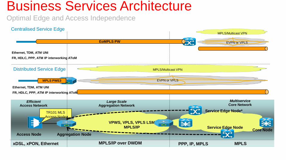
Multiservice Core Network
PPP, IP, MPLS MPLS
Service Edge Node*
Large Scale Aggregation Network
Core Node
xDSL, xPON, Ethernet
Access Node
Efficient Access Network
TR101 MLS
Access Node
VPWS, VPLS, VPLS LSM
MPLS/IP
Aggregation Node
MPLS/IP over DWDM
Service Edge Node
EoMPLS Pseudowire EoMPLS PW
Centralised Service Edge MPLS/Multicast VPN
EVPN or VPLS
MPLS PWE3
MPLS/Multicast VPN
EVPN or VPLS
Distributed Service Edge
Ethernet, TDM, ATM UNI
FR, HDLC, PPP, ATM IP interworking AToM
Ethernet, TDM, ATM UNI
FR, HDLC, PPP, ATM IP interworking AToM
Business Services Architecture Optimal Edge and Access Independence
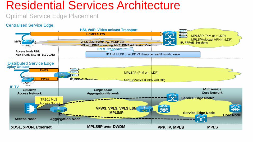
Multiservice Core Network
PPP, IP, MPLS MPLS
Service Edge Node*
Large Scale Aggregation Network
Core Node
xDSL, xPON, Ethernet
Access Node
Efficient Access Network
TR101 MLS
Access Node
VPWS, VPLS, VPLS LSM
MPLS/IP
Aggregation Node
MPLS/IP over DWDM
Service Edge Node
EoMPLS Pseudowire EoMPLS PW
IPTV Transport Access Node UNI:
Non Trunk, N:1 or 1:1 VLAN;
MPLS/IP (PIM or mLDP)
MPLS/Multicast VPN (mLDP) IP, PPPoE Sessions
Centralised Service Edge,
VPLS LSM: P2MP PW, mLDP LSP
VFI with IGMP snooping, MVR, IGMP Admission Control
HSI, VoIP, Video unicast Transport
MVR
VFI
Distributed Service Edge
PWE3
PWE3
VFI
MPLS/IP (PIM or mLDP)
MPLS/Multicast VPN (mLDP) IP, PPPoE Sessions
IP PIM, MLDP or mLPD VPN may be used if no wholesale
3play Unicast
IP TV
Residential Services Architecture Optimal Service Edge Placement

ATM or TDM
Aggregation Node
DWDM, Fiber Rings, Mesh Topology DWDM, Fiber Rings, H&S, Hierarchical Topology Fiber or uWave Link, Ring
Core Network Access Network Aggregation Network
Core Node
IP/MPLS Transport
BSC
ATM RNC
V4 or v6 MPLS VPN
SAE Gateway
TDM BTS, ATM NodeB
IP/MPLS Transport
Core Node Cell Site Gateway
IP/MPLS Transport
Mobile Transport Gateway
SAE Gateway
MME
Mobile Transport Gateway X2-C, X2-U
S1-U
S1-C
IP eNB
Mobile Transport Gateway
ASR9000
Aggregation Node
Mobile Transport Services Architecture Simplified, Scalable, and Optimized
Architecture Comparisons
The architectures options can be evaluated against the following criteria
• Capital Expenditures
• Scalability (Bandwidth / Subscriber, Transport, Policy Control)
• Operational Complexity (Troubleshooting, QoS)
• Reuse of existing Operations procedures
• Availability
• Traffic Patterns
• Economically serving areas of differing subscriber density
• Service Flexibility
• Operational Flexibility
Which one to choose?
18
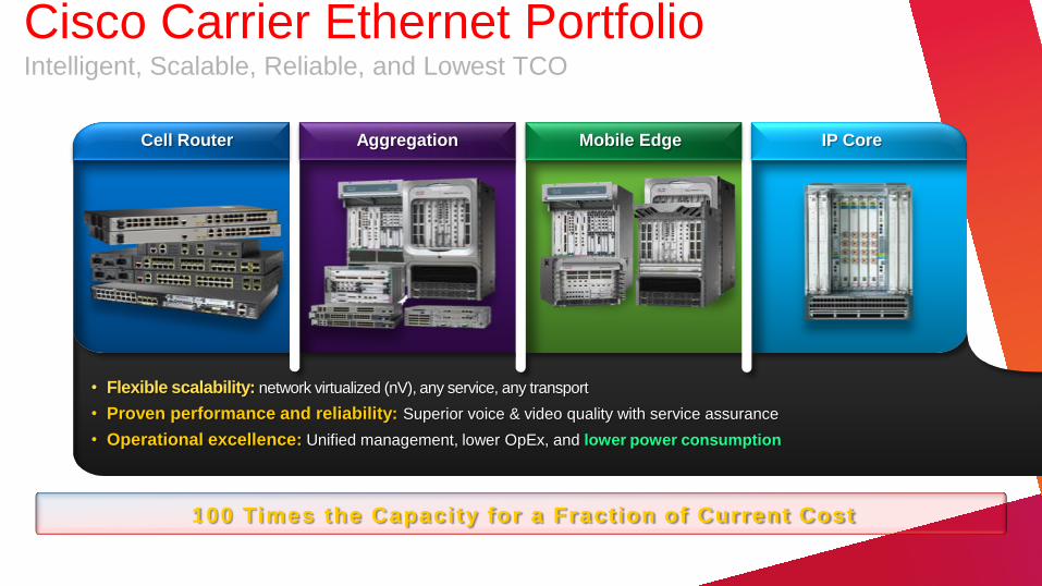
100 Times the Capacity for a Fraction of Current Cost
• Flexible scalability: network virtualized (nV), any service, any transport
• Proven performance and reliability: Superior voice & video quality with service assurance
• Operational excellence: Unified management, lower OpEx, and lower power consumption
Cell Router Aggregation IP Core Mobile Edge
Cisco Carrier Ethernet Portfolio Intelligent, Scalable, Reliable, and Lowest TCO
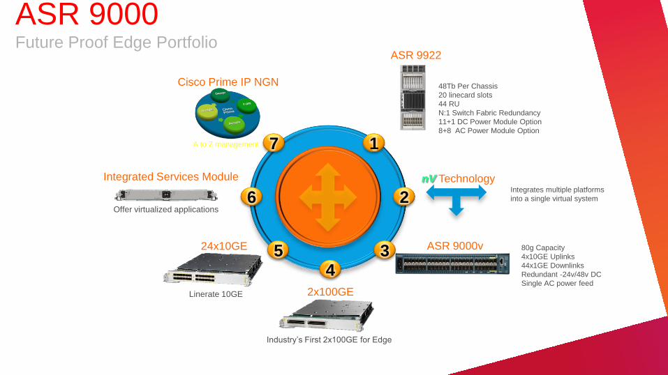
nV Technology Integrates multiple platforms
into a single virtual system 2
ASR 9000v 80g Capacity
4x10GE Uplinks
44x1GE Downlinks
Redundant -24v/48v DC
Single AC power feed
3
2x100GE
4
Industry’s First 2x100GE for Edge
Integrated Services Module
6 Offer virtualized applications
7
Cisco Prime IP NGN
A to Z management
24x10GE 5
Linerate 10GE
ASR 9922
48Tb Per Chassis
20 linecard slots
44 RU
N:1 Switch Fabric Redundancy
11+1 DC Power Module Option
8+8 AC Power Module Option
1
ASR 9000 Future Proof Edge Portfolio
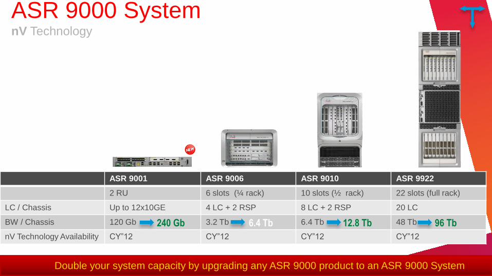
ASR 9001 ASR 9006 ASR 9010 ASR 9922
2 RU 6 slots (¼ rack) 10 slots (½ rack) 22 slots (full rack)
LC / Chassis Up to 12x10GE 4 LC + 2 RSP 8 LC + 2 RSP 20 LC
BW / Chassis 120 Gb 3.2 Tb 6.4 Tb 48 Tb
nV Technology Availability CY‖12 CY‖12 CY‖12 CY‖12
Double your system capacity by upgrading any ASR 9000 product to an ASR 9000 System
6.4 Tb 12.8 Tb 96 Tb 240 Gb
ASR 9000 System nV Technology
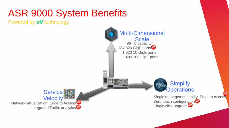
ASR 9000 System Benefits Powered by nV technology
Service Velocity
Simplify Operations
Multi-Dimensional Scale
96 Tb capacity
184,320 GigE ports
1,920 10 GigE ports
480 100 GigE ports
Single management entity: Edge to Access
Zero touch configuration
Single click upgrade Network virtualization: Edge to Access
Integrated Traffic analytics
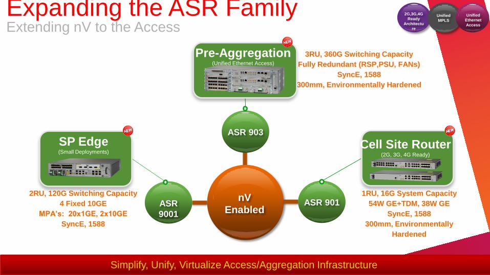
nV
Enabled
3RU, 360G Switching Capacity
Fully Redundant (RSP,PSU, FANs)
SyncE, 1588
300mm, Environmentally Hardened
2RU, 120G Switching Capacity
4 Fixed 10GE
MPA’s: 20x1GE, 2x10GE
SyncE, 1588
1RU, 16G System Capacity
54W GE+TDM, 38W GE
SyncE, 1588
300mm, Environmentally
Hardened
Simplify, Unify, Virtualize Access/Aggregation Infrastructure
ASR 903
Pre-Aggregation (Unified Ethernet Access)
ASR
9001
SP Edge (Small Deployments)
ASR 901
Cell Site Router (2G, 3G, 4G Ready)
2G,3G,4G
Ready
Architectu
re
Unified
MPLS
Unified
Ethernet
Access
Expanding the ASR Family Extending nV to the Access

Business
Edge
Residential
Third-Party Services/ Content
Aggregation
Access
Core
Converged
Cisco
Prime IP NGN
SP Services/ Content
nV
Edge and aggregation
managed as one virtual
system through Cisco Prime
IP NGN.
Single release vehicle
offering feature consistency.
Offers up to 71% reduction
in OPEX over 6 years vs
competitors.
Reduced protocol
complexity between edge
and aggregation
Up to 84,480 GE ports
managed through a single
virtual system
Each device managed
separately.
Inconsistent features
between edge and
aggregation.
Siloed service
domains.
Inconsistent service
outages upon device
failure.
Port scale limited to
chassis.
Before: nV Technology After: nV Technology
nV Cluster
nV Satellite
ASR 9000 nV Technology Overview
2
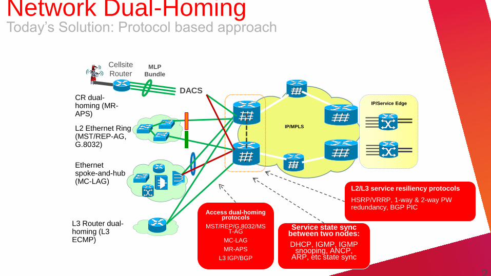
Ethernet spoke-and-hub (MC-LAG)
L2 Ethernet Ring (MST/REP-AG, G.8032)
IP/Service Edge
IP/MPLS
L3 Router dual-homing (L3 ECMP)
Cellsite
Router MLP
Bundle
DACS
L2/L3 service resiliency protocols
HSRP/VRRP, 1-way & 2-way PW redundancy, BGP PIC
CR dual-homing (MR-APS)
Service state sync between two nodes:
DHCP, IGMP, IGMP snooping, ANCP,
ARP, etc state sync
Access dual-homing protocols
MST/REP/G.8032/MST-AG
MC-LAG
MR-APS
L3 IGP/BGP
2
Network Dual-Homing Today’s Solution: Protocol based approach
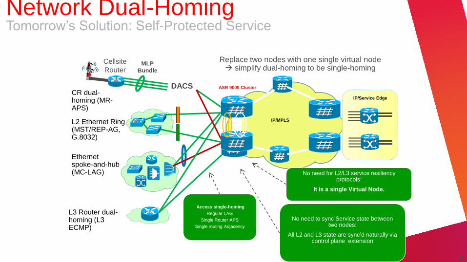
Ethernet spoke-and-hub (MC-LAG)
L2 Ethernet Ring (MST/REP-AG, G.8032)
IP/Service Edge
IP/MPLS
L3 Router dual-homing (L3 ECMP)
Cellsite
Router MLP
Bundle
DACS CR dual-homing (MR-APS)
ASR 9000 Cluster
No need to sync Service state between two nodes:
All L2 and L3 state are sync’d naturally via control plane extension
L2/L3 service resiliency protocols
NO need! It’s SINGLE virtual node
Access single-homing
Regular LAG
Single Router APS
Single routing Adjacency
Replace two nodes with one single virtual node simplify dual-homing to be single-homing
No need for L2/L3 service resiliency protocols:
It is a single Virtual Node.
2
Network Dual-Homing Tomorrow’s Solution: Self-Protected Service
• L2VPN
– SP 3Play and L2 Business VPN
– DCI (data center inter-connect) (both enterprise and SP DCI)
– Ethernet exchange
• Wireline Aggregation
– L3 termination, no IP session
• BNG (distributed or centralized)
• Wireless Back haul
• L3 CPE aggregation
Network Virtualization (nV) Deployment Scenarios

S S
A A
LACP
Standby
Active
Active PW
Standby PW
Standby
Active
LACP
Solution1: MC-LAG + 2-way PW redundancy
(Currently the best solution in the market)
Solution 2: ASR 9000 Cluster
Active/standby MC-LAG
bandwidth inefficiency
4 PWs with 3 standby
control plane overhead
PW failover time depends on
the number of PWs
slow convergence
Require additional state
sync (for example, IGMP
Snooping table) to speed up
service convergence
complex
Active/active regular LAG
Single PW
Link/Node failure is
protected by LAG, PW is
even not aware super
fast convergence
State sync naturally
Simple, fast solution
Network Virtualization (nV) Deployment Example – L2VPN Service
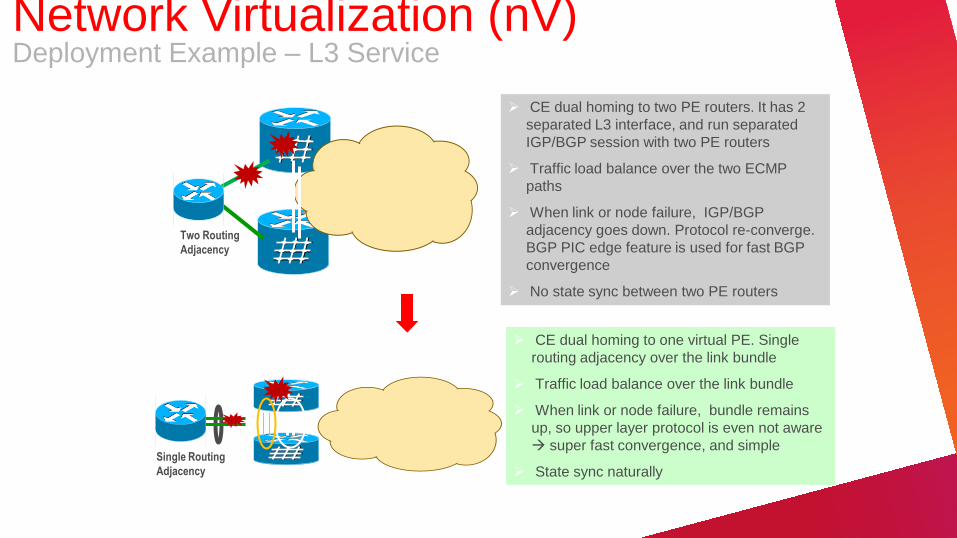
Two Routing
Adjacency
CE dual homing to two PE routers. It has 2
separated L3 interface, and run separated
IGP/BGP session with two PE routers
Traffic load balance over the two ECMP
paths
When link or node failure, IGP/BGP
adjacency goes down. Protocol re-converge.
BGP PIC edge feature is used for fast BGP
convergence
No state sync between two PE routers
Single Routing
Adjacency
CE dual homing to one virtual PE. Single
routing adjacency over the link bundle
Traffic load balance over the link bundle
When link or node failure, bundle remains
up, so upper layer protocol is even not aware
super fast convergence, and simple
State sync naturally
Network Virtualization (nV) Deployment Example – L3 Service
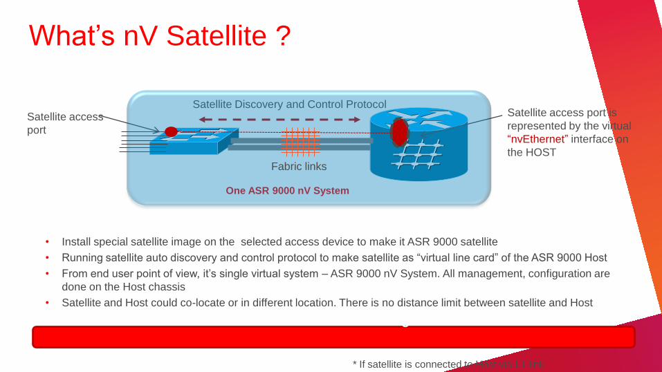
What’s nV Satellite ?
• Install special satellite image on the selected access device to make it ASR 9000 satellite
• Running satellite auto discovery and control protocol to make satellite as ―virtual line card‖ of the ASR 9000 Host
• From end user point of view, it’s single virtual system – ASR 9000 nV System. All management, configuration are
done on the Host chassis
• Satellite and Host could co-locate or in different location. There is no distance limit between satellite and Host
Satellite have zero touch configuration*
Satellite access
port
Satellite Discovery and Control Protocol
Satellite
ASR 9000 Host One ASR 9000 nV System
Satellite access port is
represented by the virtual
―nvEthernet‖ interface on
the HOST
* If satellite is connected to Host via L1 link
Fabric links
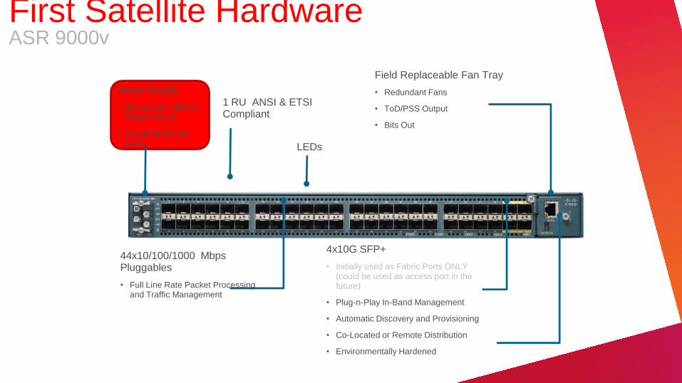
Power Feeds
• Redundant -48vDC Power Feeds
• Single AC power feed
44x10/100/1000 Mbps Pluggables
• Full Line Rate Packet Processing and Traffic Management
Field Replaceable Fan Tray
• Redundant Fans
• ToD/PSS Output
• Bits Out
4x10G SFP+
• Initially used as Fabric Ports ONLY (could be used as access port in the future)
• Plug-n-Play In-Band Management
• Automatic Discovery and Provisioning
• Co-Located or Remote Distribution
• Environmentally Hardened
1 RU ANSI & ETSI Compliant
LEDs
First Satellite Hardware ASR 9000v
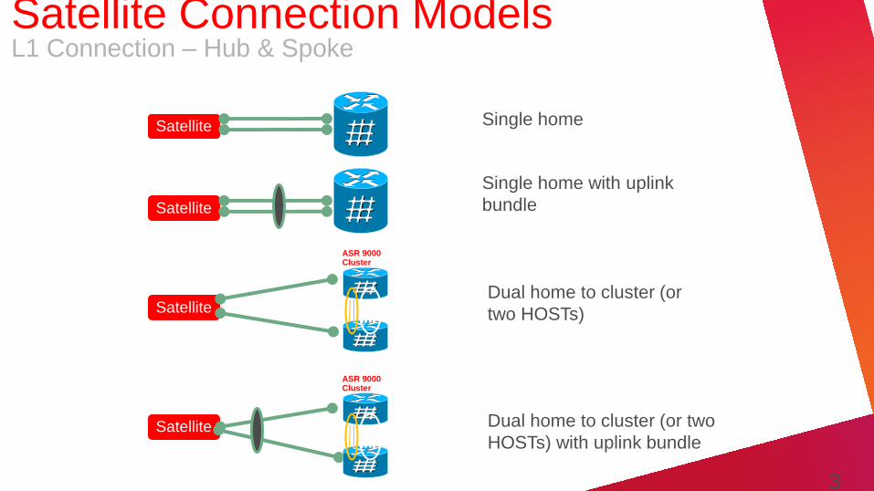
Satellite
Dual home to cluster (or
two HOSTs)
Satellite
Satellite
Satellite
ASR 9000 Cluster
ASR 9000 Cluster
Dual home to cluster (or two
HOSTs) with uplink bundle
Single home
Single home with uplink
bundle
3
2
Satellite Connection Models L1 Connection – Hub & Spoke
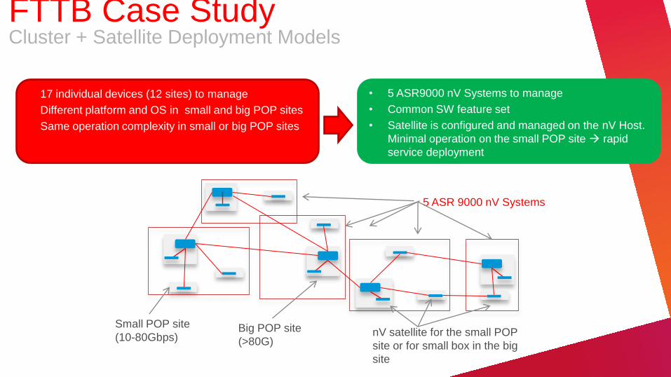
• 17 individual devices (12 sites) to manage
• Different platform and OS in small and big POP sites
• Same operation complexity in small or big POP sites
Small POP site
(10-80Gbps) Big POP site
(>80G)
5 ASR 9000 nV Systems
nV satellite for the small POP
site or for small box in the big
site
• 5 ASR9000 nV Systems to manage
• Common SW feature set
• Satellite is configured and managed on the nV Host.
Minimal operation on the small POP site rapid
service deployment
FTTB Case Study Cluster + Satellite Deployment Models

Cisco Confidential 34
MME
SGW
MSC
RNC
Mgmt
LTE Core
CDMA Core
CO
VRF Voice
VRF RAN
VRF MGMT
9000v
Cell Site Routers
GE port per
cell site router
• GE for cell site routers aggregation
• GE ports for local devices
• Limited GE density per box
• ~nx1000 GE ports
• ―unlimited‖ backhaul capacity for growth and for local
devices
9000v
9000v
9000v
9000v
9000v
Mobile Aggregation Case Study Cluster + Satellite Deployment Models
Satellite Satellite Satellite Satellite
cluster
Traditional wireline GE
aggregation via L2 switch One ASR 9000 nV System
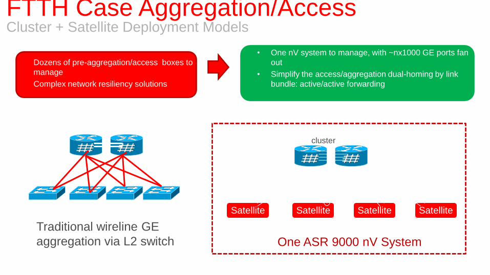
• One nV system to manage, with ~nx1000 GE ports fan
out
• Simplify the access/aggregation dual-homing by link
bundle: active/active forwarding
• Dozens of pre-aggregation/access boxes to
manage
• Complex network resiliency solutions
FTTH Case Aggregation/Access Cluster + Satellite Deployment Models
Cisco Confidential 36
MME
SGW
MSC
RNC
Mgmt
LTE Core
CDMA Core
CO
VRF Voice
VRF RAN
VRF MGMT
Cell Site Routers
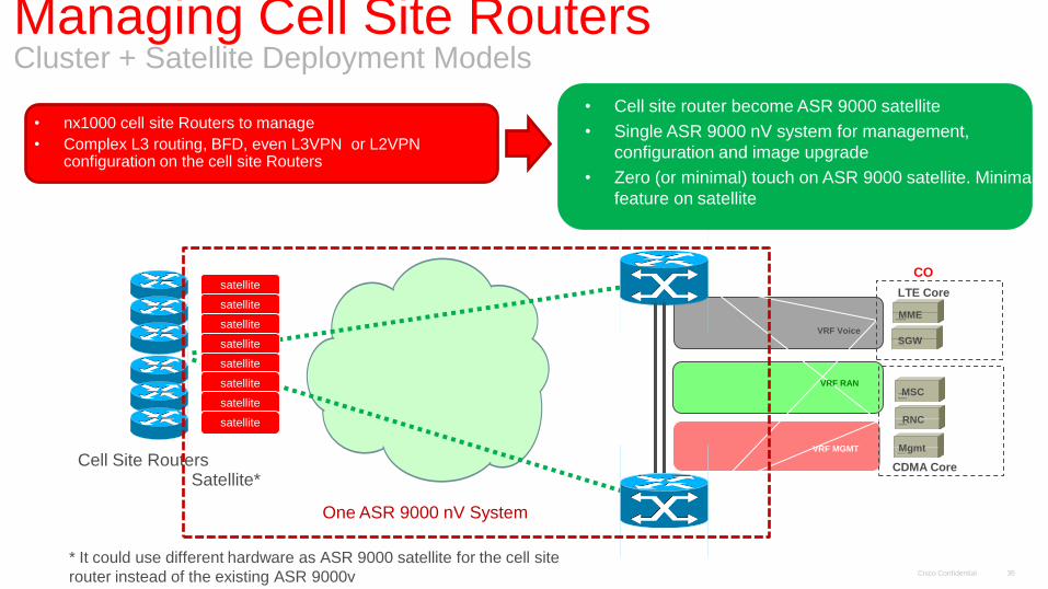
• nx1000 cell site Routers to manage
• Complex L3 routing, BFD, even L3VPN or L2VPN configuration on the cell site Routers
• Cell site router become ASR 9000 satellite
• Single ASR 9000 nV system for management,
configuration and image upgrade
• Zero (or minimal) touch on ASR 9000 satellite. Minimal
feature on satellite
satellite
satellite
satellite
satellite
satellite
satellite
satellite
satellite
Satellite*
One ASR 9000 nV System
* It could use different hardware as ASR 9000 satellite for the cell site
router instead of the existing ASR 9000v
Managing Cell Site Routers Cluster + Satellite Deployment Models
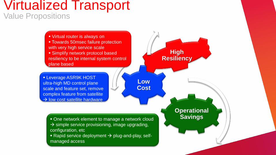
Operational Savings
Low Cost
High Resiliency
Virtual router is always on
Towards 50msec failure protection
with very high service scale
Simplify network protocol based
resiliency to be internal system control
plane based
Leverage ASR9K HOST
ultra-high MD control plane
scale and feature set, remove
complex feature from satellite
low cost satellite hardware
One network element to manage a network cloud
simple service provisioning, image upgrading,
configuration, etc
Rapid service deployment plug-and-play, self-
managed access
Virtualized Transport Value Propositions
Cisco Confidential 38
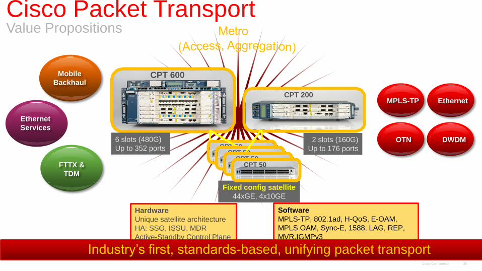
Mobile
Backhaul
FTTX &
TDM
CPT 600
CPT 200
Fixed config satellite
44xGE, 4x10GE
Hardware
Unique satellite architecture
HA: SSO, ISSU, MDR
Active-Standby Control Plane
6 slots (480G)
Up to 352 ports 2 slots (160G)
Up to 176 ports
Software
MPLS-TP, 802.1ad, H-QoS, E-OAM,
MPLS OAM, Sync-E, 1588, LAG, REP,
MVR,IGMPv3
Ethernet
Services
MPLS-TP
DWDM
Ethernet
OTN
Industry’s first, standards-based, unifying packet transport
CPT 50 CPT 50
CPT 50 CPT 50
Cisco Packet Transport Value Propositions
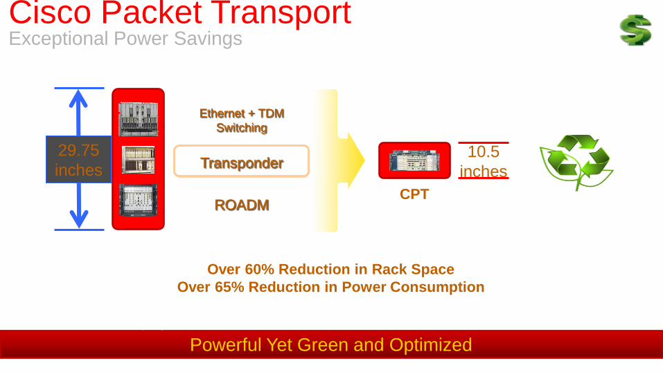
Powerful Yet Green and Optimized
Calculations based on 480G capacity
Over 60% Reduction in Rack Space
Over 65% Reduction in Power Consumption
Ethernet + TDM
Switching
Transponder
ROADM
Ethernet + TDM
Switching
Transponder
ROADM
29.75
inches 10.5
inches
CPT
Cisco Packet Transport Exceptional Power Savings

POT-S and IPoDWDM complementary
TDM
Carrier Ethernet
IP & MPLS Routers
OTN
Private Lines
Eth & TDM
IP & MPLS
POT-S
IPoDWDM
Carrier Ethernet
DWDM Switching Point-to-point
Point-to-point
& multipoint
Private Lines
Eth & TDM
TDM
POT-S in Metro Deployment Scenario
Business
Connection-
oriented, P2P /
P2MP
In-band OAM
Rich set of connections
(mesh), P2P / P2MP /
MP2MP
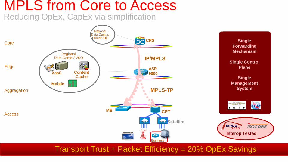
MPLS-TP
IP/MPLS Single
Forwarding
Mechanism
Single Control
Plane
Single
Management
System
IP/MPLS
MPLS-TP
ASR
9000
CPT
Satellite
ME
National Data Center/ Cloud/VHO
CRS
XaaS Content Cache
Mobile
Regional Data Center/ VSO
Core
Edge
Aggregation
Access
Transport Trust + Packet Efficiency = 20% OpEx Savings
Interop Tested
MPLS from Core to Access Reducing OpEx, CapEx via simplification
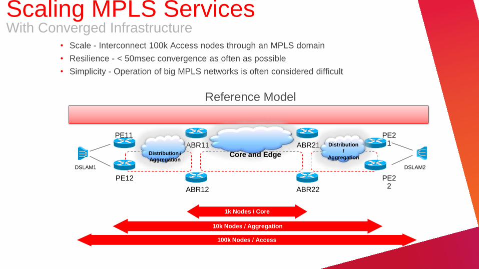
• Scale - Interconnect 100k Access nodes through an MPLS domain
• Resilience - < 50msec convergence as often as possible
• Simplicity - Operation of big MPLS networks is often considered difficult
1k Nodes / Core
10k Nodes / Aggregation
100k Nodes / Access
Reference Model
DSLAM1
PE11
PE12
ABR11
ABR12
ABR21
ABR22
PE21
PE22
DSLAM2
Core and Edge Distribution /
Aggregation
Distribution
/
Aggregation
Scaling MPLS Services With Converged Infrastructure

Virtualized Functions
Storage
Compute
Data
Center
Switch
Transcode
Consumer
Apps Video
Processing Billing
Svc Delivery
Origin
Server Encryption
Device Mgmt
Core
Cloud
Consumer Business Mobile
Client
Devices
Aggregation
Unified
MPLS
Converged: Any Service, Any
Path, Any Access
Operationally Simple: Single
Control Plane
Carrier Class: Fast Reroute and
Network Convergence
Edge
Solution - Unified MPLS Carrier Ethernet Transport Architecture
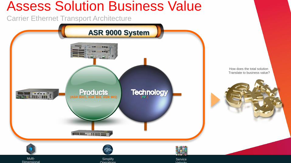
Service Velocity
How does the total solution
Translate to business value?
Multi-Dimensional
Scale
Simplify Operations
(nV ) (ASR 9001, ASR 903, ASR 901)
Single Management
Entity
Zero Touch
Configuration
Integrated
Traffic Analytics
ASR 9000 System
Assess Solution Business Value Carrier Ethernet Transport Architecture

TCO
CAPEX
OPEX
3 Year Period
Mobile
Res
Biz
CAPEX
• Average Sales Price (ASP)
• Engineering, Furnishing and Installation (EF&I)
OPEX
• Power
• Cooling
• Floor Space
• Network Care (provisioning, fault management, performance management)
• Software upgrades
• Vendor maintenance
Competitive TCO Analysis Input Various TCO Parameters
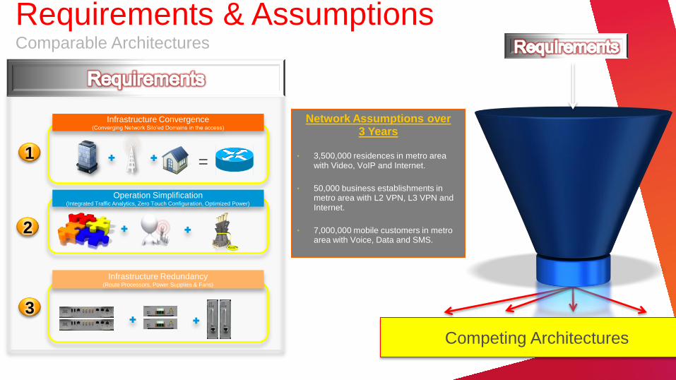
Network Assumptions over 3 Years
• 3,500,000 residences in metro area with Video, VoIP and Internet.
• 50,000 business establishments in metro area with L2 VPN, L3 VPN and Internet.
• 7,000,000 mobile customers in metro area with Voice, Data and SMS.
3
Infrastructure Redundancy (Route Processors, Power Supplies & Fans)
2
Operation Simplification (Integrated Traffic Analytics, Zero Touch Configuration, Optimized Power)
1
Infrastructure Convergence (Converging Network Silo’ed Domains in the access)
=
Competing Architectures
Requirements & Assumptions Comparable Architectures
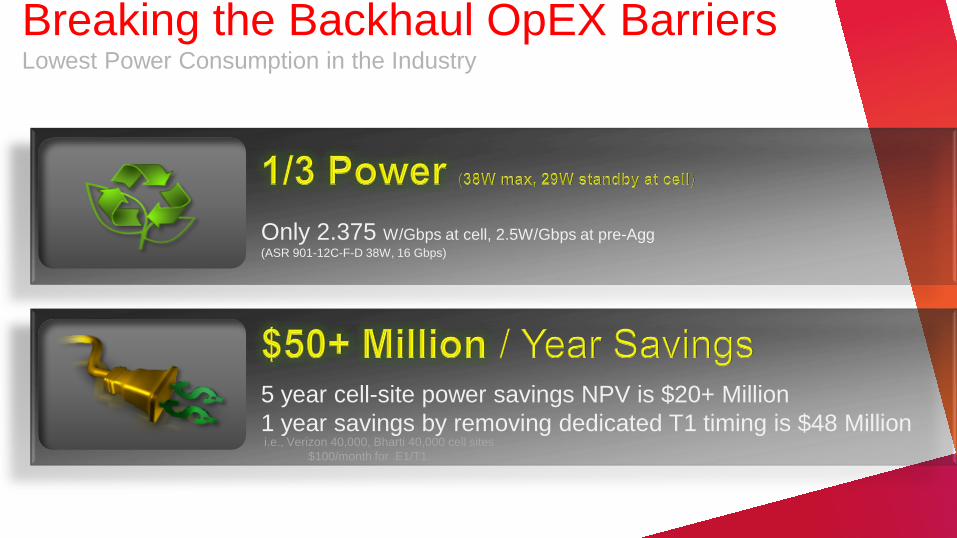
Only 2.375 W/Gbps at cell, 2.5W/Gbps at pre-Agg (ASR 901-12C-F-D 38W, 16 Gbps)
5 year cell-site power savings NPV is $20+ Million
1 year savings by removing dedicated T1 timing is $48 Million
i.e., Verizon 40,000, Bharti 40,000 cell sites
$100/month for E1/T1
Breaking the Backhaul OpEX Barriers Lowest Power Consumption in the Industry
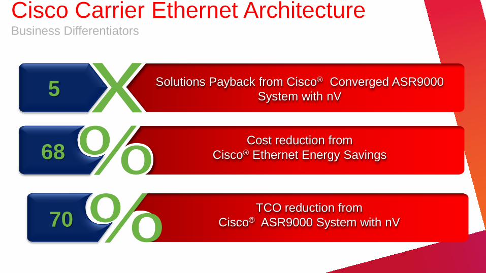
Solutions Payback from Cisco® Converged ASR9000
System with nV 5
Cost reduction from
Cisco® Ethernet Energy Savings 68
70 TCO reduction from
Cisco® ASR9000 System with nV
Cisco Carrier Ethernet Architecture Business Differentiators

Q&A
#CiscoPlusCA
Follow @CiscoCanada and join the #CiscoPlusCA conversation
Access today’s presentations at cisco.com/ca/plus
We value your feedback. Please be sure to complete the Evaluation Form for this session.
51 51
Working LSP
PE PE
Protect LSP
NMS for Network Management
or Dynamic Control Plane
Client node Client node
MPLS-TP LSP (Static or Dynamic)
Pseudowire
Client Signal
with e2e and
segment OAM Section Section
Connection Oriented, pre-determined working path and protect path
Transport Tunnel 1:1 protection, switching triggered by in-band OAM,
Options with NMS for static provisioning, or dynamic control plane for routing and signaling
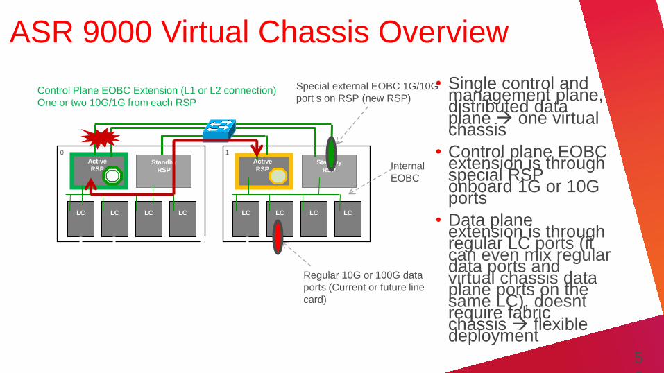
ASR 9000 Virtual Chassis Overview
• Single control and management plane, distributed data plane one virtual chassis
• Control plane EOBC extension is through special RSP onboard 1G or 10G ports
• Data plane extension is through regular LC ports (it can even mix regular data ports and virtual chassis data plane ports on the same LC), doesnt require fabric chassis flexible deployment
Control Plane EOBC Extension (L1 or L2 connection)
One or two 10G/1G from each RSP
Inter-chassis data link (L1
connection)
10G or 100 G bundle (up to 32 ports)
Special external EOBC 1G/10G
port s on RSP (new RSP)
Regular 10G or 100G data
ports (Current or future line
card)
Active
RSP Standby
RSP
LC LC LC LC
0
Active
RSP Standby
RSP
LC LC LC LC
1
Internal
EOBC
5
2
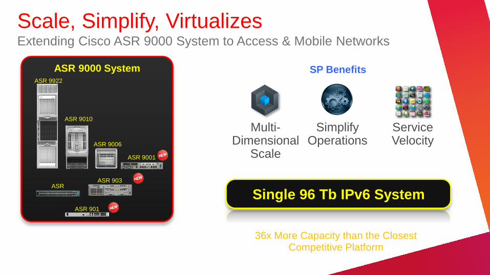
ASR 9000 System
Service Velocity
SP Benefits
Simplify Operations
Multi-Dimensional
Scale ASR 9006
ASR 9010
ASR 9000v
ASR 9922
Single 96 Tb IPv6 System
36x More Capacity than the Closest Competitive Platform
Scale, Simplify, Virtualizes Extending Cisco ASR 9000 System to Access & Mobile Networks
ASR 903
ASR 901
ASR 9001