Embed Size (px)
Citation preview
Arch. Metall. Mater. 62 (2017), 3, 1433-1437
DOI: 10.1515/amm-2017-0221
A. JASIK*#
THE NUMERICAL MODELING OF THERMAL STRESS DISTRIBUTION IN THERMAL BARRIER COATINGS
The paper presents the results of numerical calculations of temperature and thermal stress distribution in thermal barrier coatings deposited by thermal spraying process on the nickel based superalloy. An assumption was made to apply conventional zirconium oxide modified with yttrium oxide (8YSZ) and apply pyrochlore type material with formula La2Zr2O7. The bond coat was made of NiCoCrAlY. Analysis of the distribution of temperature and stresses in ceramic coatings of different thicknesses was performed in the function of bond-coat thickness and the type of ceramic insulation layer. It was revealed that the thickness of NiCrAlY bond-coat has not significant influence on the stress distribution, but there is relatively strong effect on temperature level. The most important factor influenced on stress distribution in TBC system is related with type and properties of ceramic insulation layer.
Keywords: temperature distribution, thermal stress, TBC, FEM
1. Introduction
A thermal field which emerges in a solid body subject to deformation is a reason why both permanent and temporary states of strain and stress emerge in that body. Value changes and temperature distribution cause thermal stresses to emerge. These stresses exert considerable impact on the operation, mechanical strength and service life of structural components and systems. Determination of thermal stresses is particularly crucial in practi-cal terms for such objects as power engineering machinery and equipment, combustion engines, mechanical vehicles, aircrafts and spaceships or steel working devices [1]. As a result of ther-mal stresses which accompany the processes of production and operation of elements consisting of parts characterised by dif-ferent mechanical and thermal properties, one must account for the possibility of internal stresses occurring in the element after its temperature has settled. This problem matters for numerous reasons, including those related to interfaces between ceramic and metallic materials [2-6]. Internal stresses combined with stresses triggered by thermal or mechanical loads may lead to destruction of an element. Effective solving of many complex problems has become possible owing to the development of numerical methods, with the finite element method (FEM) being among the most important ones. From the technical perspective, a significant example of application of the said method may be determination of non-stationary thermal fields and fields of ther-mal stresses in heat generating turbines or elements of reaction engines. In order to assess reliability and durability of thermal barrier coatings (TBC), one must first analyse thermal insulation as well as problems of mechanical strength of TBCs. What plays
an important role in the study of the aforementioned problems is the finite element method (FEM) which is mainly used for calculations related to thermal insulation as well as problems of durability of TBC layers. The finite element method is also applied to determine internal stresses emerging in the process of plasma spraying or being caused by mismatch of thermal expansion coefficient values between the coating and the sub-strate. Numerical methods are also used to establish changes in the temperature gradient values under real operating conditions. A solution to the aforementioned problems is based on thermal and mechanical calculations.
This article provides a discussion on results of numerical studies concerning characteristics of the impact exerted by the ceramic material used on the distribution of stresses in thermal barrier coatings. The assumed point of reference was a set of conventional TBCs made of the 8YSZ powder with the insulating layer thickness ranging between 150 μm and 300 μm. Similarly assumed for numerical analysis pyrochlore type material with formula La2Zr2O7. For all cases it was assumed that the bond-coat would be the NiCoCrAlY type coat obtained by plasma spraying similarly to the outer insulating layer. The bond-coat depth ranged from 150 μm to 300 μm. The assumed substrate material was the In 625 type nickel superalloy.
Thermal barrier coatings are some of the most highly advanced protective systems applied in the aircraft industry. Typical structure of a thermal barrier coating includes four layers: superalloy substrate, bond coat, thermally grown oxide (TGO), and ceramic top coat. The nickel and cobalt based su-peralloy substrate is air cooled from the inside. The bond-coat is an oxidation-resistant layer which also has a close thermal
* SILESIAN UNIVERSITY OF TECHNOLOGY, INSTITUE OF METALS TECHNOLOGY, KATOWICE, POLAND# Corresponding author: [email protected]
1434
expansion coefficient with the substrate, so that there is less stress due to differential thermal expansions. Typically bond coat consists of a NiCoCrAlY alloy with a thickness of 100 μm by air plasma spraying (APS) or electron-beam physical vapor deposition (EB-PVD) methods. The last element of the thermal barrier coating is a ceramic insulating layer. The material typi-cally used to build this layer is zirconium oxide stabilised with yttrium oxide at the weight ratio of ca. 7-8% Y2O3, designated as 8YSZ. The foregoing stems from its superior insulating properties. 8YSZ is known of a very low thermal conductivity coefficient which equals 2.3 W/mK, and some other of its advan-tages are the low thermal expansion coefficient (11×10–6 °C–1) and low density of ca. 6.04 g/cm3. What also proves to be a very important property of the 8YSZ oxide is the melting point which comes to ca. 2700°C, owing to which it is possible to use it in hot sections of aircraft engines [7-10]. Whereas La2Zr2O7 top coat has a thermal conductivity about 1.55W/m/K at 1000°C at fully dense [11-12]. La2Zr2O7 has a lower thermal conductivity than 8YSZ. La2Zr2O7 is thermally stable during the heating and cooling stages. La2Zr2O7 can be a better contestant for advanced thermal barrier coating.
Research methodology. This paper addresses a numerical analysis of heat flux in model thermal barrier coatings conducted by application of the finite element method (FEM). Algor was the program used for computer simulation.
While developing the numerical model in the Algor pro-gram, it is necessary to build it as well as to define it, which proceeds in the following several steps:• defining the shape;• building a geometric model;• defining the material;• comparing elements of the geometric model;• determining the analysis type;• defining interactions (contact conditions);• defining the type of loads and boundary conditions;• model discretisation by introducing a grid of finite elements;• defining conditions for calculations.
The research comprised an analysis of elastic strains. Its initial stage was a numerical analysis of the thermal field. Bound-ary conditions of the first kind were defined. Temperature load was assumed accordingly on the model’s surfaces. Temperature of 1200°C was applied on the surface of the 8YSZ and La2Zr2O7 ceramic layer, whereas the temperature assumed for the outer surface of the nickel superalloy layer was 800°C.
The next stage of the study was determination of distribution of thermal stresses in the models developed. Specific constrains were set against the freedom of the models. It was assumed that cross sections of the models were not moving in the direction of the z axis. Since the axial-symmetric thermal field was known in the analysed models, it was possible to establish the state of stress which occurred in them.
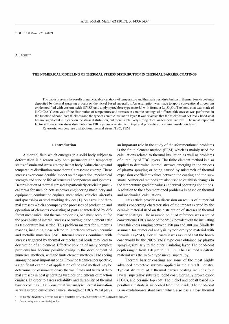
In the course of the study, distribution of thermal stress in two areas of the models was analysed. The zones of temperature and stress distribution studied have been illustrated in Figure 1. It is the area of interface between the ceramic material and the
bond coat (I) as well as between the bond coat and the metallic substrate (II). With regard to all the cases studied, graphs were developed to illustrate the temperature and stress change depend-ing on the variable thickness of individual layers.
I II
Fig. 1. Areas where temperature and stress distribution was studied: I – ceramic-NiCoCrAlY interface, II – NiCoCrAlY-In625 interface
2. Results of numerical calculations
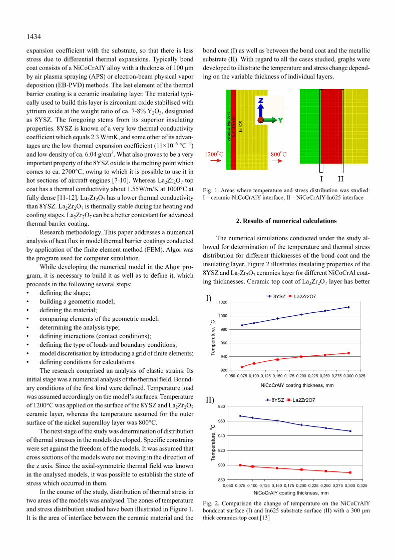
The numerical simulations conducted under the study al-lowed for determination of the temperature and thermal stress distribution for different thicknesses of the bond-coat and the insulating layer. Figure 2 illustrates insulating properties of the 8YSZ and La2Zr2O7 ceramics layer for different NiCoCrAl coat-ing thicknesses. Ceramic top coat of La2Zr2O7 layer has better
920
940
960
980
1000
1020
0,050 0,075 0,100 0,125 0,150 0,175 0,200 0,225 0,250 0,275 0,300 0,325
NiCoCrAlY coating thickness, mm
Tem
pera
ture
, o C
8YSZ La2Zr2O7
880
900
920
940
960
980
0,050 0,075 0,100 0,125 0,150 0,175 0,200 0,225 0,250 0,275 0,300 0,325
NiCoCrAlY coating thickness, mm
Tem
pera
ture
, 0 C
8YSZ La2Zr2O7
I)
II)
Fig. 2. Comparison the change of temperature on the NiCoCrAlY bondcoat surface (I) and In625 substrate surface (II) with a 300 μm thick ceramics top coat [13]
1435
insulating properties than 8YSZ regardless of the NiCoCrAl coating thicknesses, as shown in Fig. 2. The difference tem-perature is on the level of 60°C between bond coat surface (I) and In625 substrate surface (II). Additionally the increasing of the bond-coat top-surface temperature with increasing of bond-coat thickness was detected in contrast to decreasing of In-625 substrate` surface temperature in the same condition.
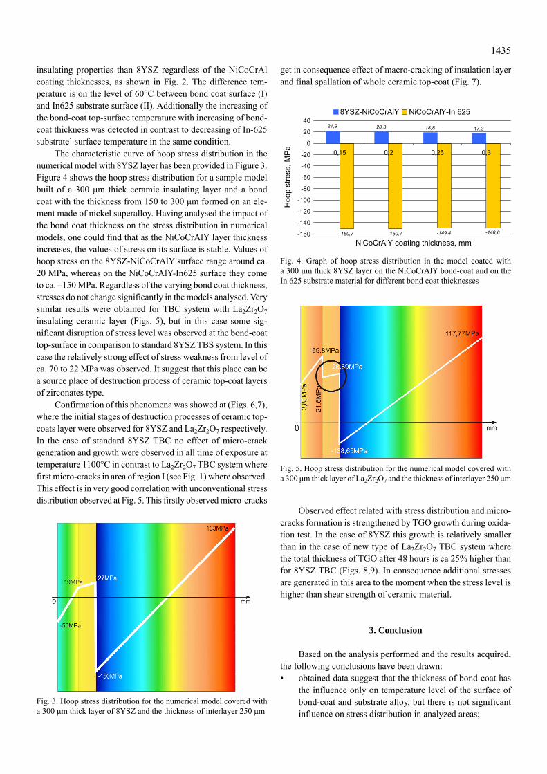
The characteristic curve of hoop stress distribution in the numerical model with 8YSZ layer has been provided in Figure 3. Figure 4 shows the hoop stress distribution for a sample model built of a 300 μm thick ceramic insulating layer and a bond coat with the thickness from 150 to 300 μm formed on an ele-ment made of nickel superalloy. Having analysed the impact of the bond coat thickness on the stress distribution in numerical models, one could find that as the NiCoCrAlY layer thickness increases, the values of stress on its surface is stable. Values of hoop stress on the 8YSZ-NiCoCrAlY surface range around ca. 20 MPa, whereas on the NiCoCrAlY-In625 surface they come to ca. –150 MPa. Regardless of the varying bond coat thickness, stresses do not change significantly in the models analysed. Very similar results were obtained for TBC system with La2Zr2O7 insulating ceramic layer (Figs. 5), but in this case some sig-nificant disruption of stress level was observed at the bond-coat top-surface in comparison to standard 8YSZ TBS system. In this case the relatively strong effect of stress weakness from level of ca. 70 to 22 MPa was observed. It suggest that this place can be a source place of destruction process of ceramic top-coat layers of zirconates type.
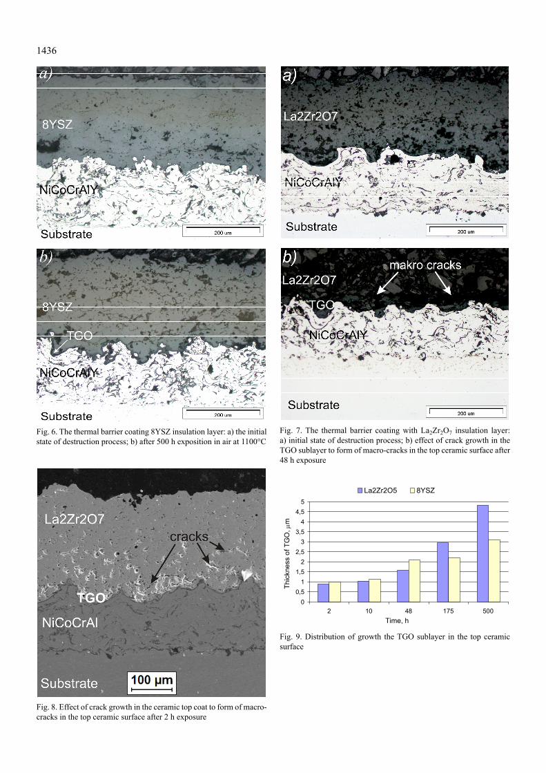
Confirmation of this phenomena was showed at (Figs. 6,7), where the initial stages of destruction processes of ceramic top-coats layer were observed for 8YSZ and La2Zr2O7 respectively. In the case of standard 8YSZ TBC no effect of micro-crack generation and growth were observed in all time of exposure at temperature 1100°C in contrast to La2Zr2O7 TBC system where first micro-cracks in area of region I (see Fig. 1) where observed. This effect is in very good correlation with unconventional stress distribution observed at Fig. 5. This firstly observed micro-cracks
get in consequence effect of macro-cracking of insulation layer and final spallation of whole ceramic top-coat (Fig. 7).
21,9 20,3 18,8 17,3
-150,7 -150,7 -149,4 -148,6-160
-140
-120
-100
-80
-60
-40
-20
0
20
40
0,15 0,2 0,25 0,3
NiCoCrAlY coating thickness, mm
Hoo
p st
ress
, MPa
8YSZ-NiCoCrAlY NiCoCrAlY-In 625
Fig. 4. Graph of hoop stress distribution in the model coated with a 300 μm thick 8YSZ layer on the NiCoCrAlY bond-coat and on the In 625 substrate material for different bond coat thicknesses
Fig. 5. Hoop stress distribution for the numerical model covered with a 300 μm thick layer of La2Zr2O7 and the thickness of interlayer 250 μm
Observed effect related with stress distribution and micro-cracks formation is strengthened by TGO growth during oxida-tion test. In the case of 8YSZ this growth is relatively smaller than in the case of new type of La2Zr2O7 TBC system where the total thickness of TGO after 48 hours is ca 25% higher than for 8YSZ TBC (Figs. 8,9). In consequence additional stresses are generated in this area to the moment when the stress level is higher than shear strength of ceramic material.
3. Conclusion
Based on the analysis performed and the results acquired, the following conclusions have been drawn:• obtained data suggest that the thickness of bond-coat has
the influence only on temperature level of the surface of bond-coat and substrate alloy, but there is not significant influence on stress distribution in analyzed areas;
Fig. 3. Hoop stress distribution for the numerical model covered with a 300 μm thick layer of 8YSZ and the thickness of interlayer 250 μm
1436
Fig. 6. The thermal barrier coating 8YSZ insulation layer: a) the initial state of destruction process; b) after 500 h exposition in air at 1100°C
Fig. 7. The thermal barrier coating with La2Zr2O7 insulation layer: a) initial state of destruction process; b) effect of crack growth in the TGO sublayer to form of macro-cracks in the top ceramic surface after 48 h exposure
Fig. 8. Effect of crack growth in the ceramic top coat to form of macro-cracks in the top ceramic surface after 2 h exposure
00,5
11,5
22,5
33,5
44,5
5
2 10 48 175 500Time, h
Thic
knes
s of
TG
O,
m
La2Zr2O5 8YSZ
Fig. 9. Distribution of growth the TGO sublayer in the top ceramic surface
1437
• critical factor having influence on the stress level distribu-tion is related with type of ceramic material used as an insulating layer in TBC system;
• due to higher level of E modulus of zirconate materials such as La2Zr2O7 in comparisons to 8YSZ, the significant differ-ences in stress level was observed in the case of La2Zr2O7 TBC was observed;
• this differences take the reflection in real behavior of ana-lyzed systems during oxidation test, where the fast destruc-tion of La2Zr2O7 TBC system was observed between 2 and 48 hours of test.
• the place of observed destruction initiation (the area of bottom of TGO zone) is in very good correlation to data obtained from numerical simulation. Observed effect was strengthened by differences in TGO thickness.
Acknowledgements
This work was supported by Polish Ministry for Science and Higher Education under internal grant BK264/RM2/2016 for Institute of Metals Technology, Silesian University of Technology, Poland.
REFERENCES
[1] Z. Orłoś, Naprężenia cieplne, Wydawnictwo Naukowe PWN, Warszawa (1991).
[2] Wł. Włosiński, Połączenia ceramiczno-metalowe. Wyd. Nauk. PWN, Warszawa (1984).
[3] W.A. Zdaniewski, J.C. jr. Conway, H.P. Kirchner, J. of the Ame-rican Ceramic Society 70 (2), (1987).
[4] A.P. Gopkalo, A.V. Rutkovskyy, Fatigue & Fracture of Eng. Materials & Structures 34, 12, 1012-1020 (2011).
[5] V. Cazajus, S. Seguy, H. Welemane, M. Karama, Applied Mecha-nics and Materials 146, 185-196 (2012).
[6] MRS Bulletin, Thermal-barrier coatings for more efficient gas – turbine engines, nr 10, Cambridge University (2012).
[7] G. Moskal, L. Swadźba, M. Hetmańczyk, at al., J. of the European Ceramic Society 32, 2035-2042 (2012).
[8] G. Moskal., A. Jasik, J. Therm. Anal. Calorimetry 126 (1), 9-17 (2016).
[9] L. Swadźba, G. Moskal, B. Mendala, M. Hetmańczyk, Arch. of Metallurgy and Materials 53 (3), 945-954 (2008).
[10] G. Moskal, A. Rozmysłowska, Advanced Materials Research 89, 739-744 (2010).
[11] X. Guo, J. Hang, Materials Today: Proceedings 1, 25-34 (2014).[12] R. Vassen, et al., J. of the American Ceramic Society, 83 (8),
2023-2028 (2000).[13] A. Jasik, Rudy Metale 61 (2), 78-82 (2016).