Embed Size (px)
Citation preview
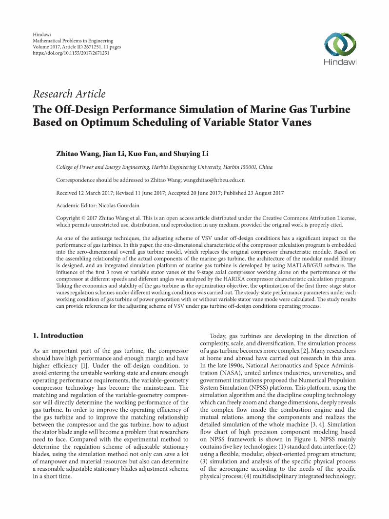
Research ArticleThe Off-Design Performance Simulation of Marine Gas TurbineBased on Optimum Scheduling of Variable Stator Vanes
ZhitaoWang, Jian Li, Kuo Fan, and Shuying Li
College of Power and Energy Engineering, Harbin Engineering University, Harbin 150001, China
Correspondence should be addressed to Zhitao Wang; [email protected]
Received 12 March 2017; Revised 11 June 2017; Accepted 20 June 2017; Published 23 August 2017
Academic Editor: Nicolas Gourdain
Copyright © 2017 Zhitao Wang et al. This is an open access article distributed under the Creative Commons Attribution License,which permits unrestricted use, distribution, and reproduction in any medium, provided the original work is properly cited.
As one of the antisurge techniques, the adjusting scheme of VSV under off-design conditions has a significant impact on theperformance of gas turbines. In this paper, the one-dimensional characteristic of the compressor calculation program is embeddedinto the zero-dimensional overall gas turbine model, which replaces the original compressor characteristic module. Based onthe assembling relationship of the actual components of the marine gas turbine, the architecture of the modular model libraryis designed, and an integrated simulation platform of marine gas turbine is developed by using MATLAB/GUI software. Theinfluence of the first 3 rows of variable stator vanes of the 9-stage axial compressor working alone on the performance of thecompressor at different speeds and different angles was analyzed by the HARIKA compressor characteristic calculation program.Taking the economics and stability of the gas turbine as the optimization objective, the optimization of the first three-stage statorvanes regulation schemes under different working conditions was carried out.The steady-state performance parameters under eachworking condition of gas turbine of power generation with or without variable stator vane mode were calculated. The study resultscan provide references for the adjusting scheme of VSV under gas turbine off-design conditions operating process.
1. Introduction
As an important part of the gas turbine, the compressorshould have high performance and enough margin and havehigher efficiency [1]. Under the off-design condition, toavoid entering the unstable working state and ensure enoughoperating performance requirements, the variable-geometrycompressor technology has become the mainstream. Thematching and regulation of the variable-geometry compres-sor will directly determine the working performance of thegas turbine. In order to improve the operating efficiency ofthe gas turbine and to improve the matching relationshipbetween the compressor and the gas turbine, how to adjustthe stator blade angle will become a problem that researchersneed to face. Compared with the experimental method todetermine the regulation scheme of adjustable stationaryblades, using the simulation method not only can save a lotof manpower and material resources but also can determinea reasonable adjustable stationary blades adjustment schemein a short time.
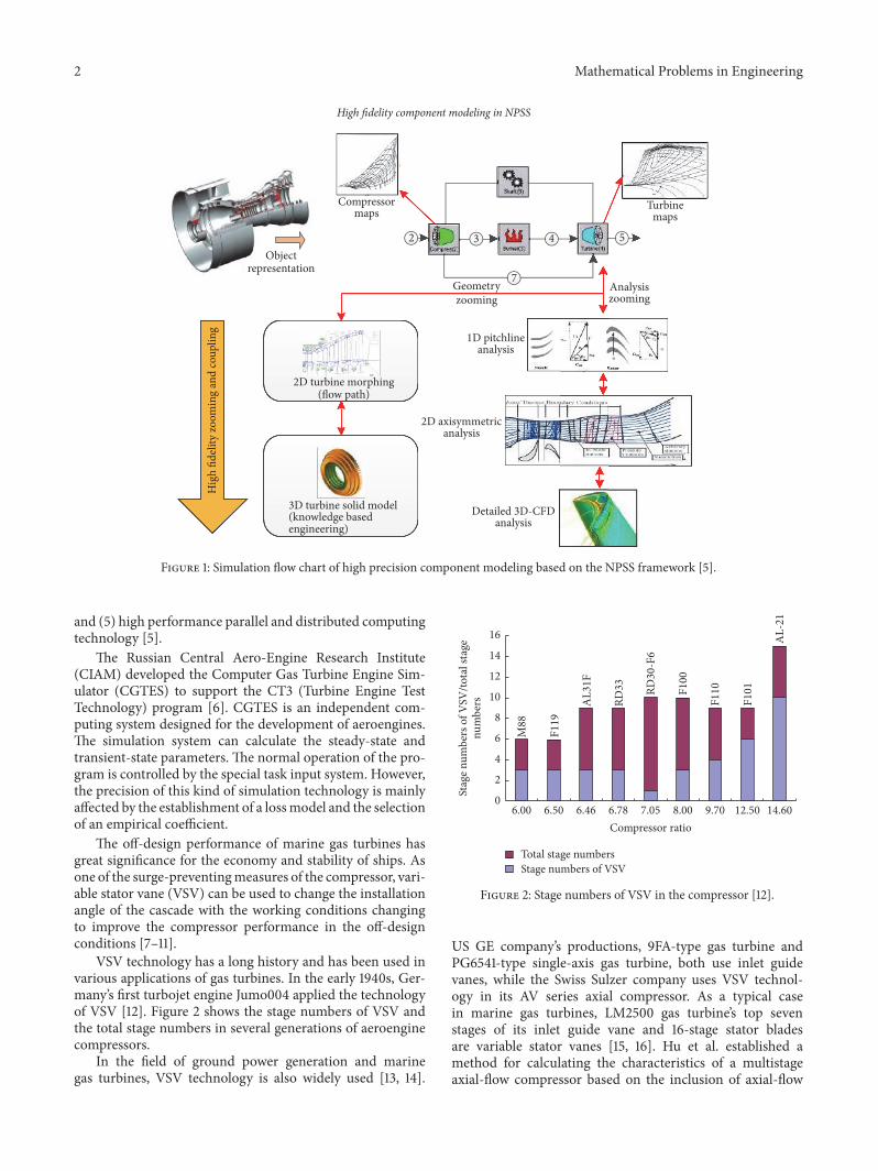
Today, gas turbines are developing in the direction ofcomplexity, scale, and diversification.The simulation processof a gas turbine becomesmore complex [2].Many researchersat home and abroad have carried out research in this area.In the late 1990s, National Aeronautics and Space Adminis-tration (NASA), united airlines industries, universities, andgovernment institutions proposed the Numerical PropulsionSystem Simulation (NPSS) platform.This platform, using thesimulation algorithm and the discipline coupling technologywhich can freely zoomand change dimensions, deeply revealsthe complex flow inside the combustion engine and themutual relations among the components and realizes thedetailed simulation of the whole machine [3, 4]. Simulationflow chart of high precision component modeling basedon NPSS framework is shown in Figure 1. NPSS mainlycontains five key technologies: (1) standard data interface; (2)using a flexible, modular, object-oriented program structure;(3) simulation and analysis of the specific physical processof the aeroengine according to the needs of the specificphysical process; (4) multidisciplinary integrated technology;
HindawiMathematical Problems in EngineeringVolume 2017, Article ID 2671251, 11 pageshttps://doi.org/10.1155/2017/2671251
2 Mathematical Problems in Engineering
High �delity component modeling in NPSS
Compressormaps
2 3 4 5
7
Objectrepresentation
Turbinemaps
Hig
h �d
elity
zoom
ing
and
coup
ling
2D turbine morphing(�ow path)
3D turbine solid model(knowledge basedengineering)
Analysiszooming
Geometryzooming
1D pitchlineanalysis
2D axisymmetricanalysis
Detailed 3D-CFDanalysis
Figure 1: Simulation flow chart of high precision component modeling based on the NPSS framework [5].
and (5) high performance parallel and distributed computingtechnology [5].
The Russian Central Aero-Engine Research Institute(CIAM) developed the Computer Gas Turbine Engine Sim-ulator (CGTES) to support the CT3 (Turbine Engine TestTechnology) program [6]. CGTES is an independent com-puting system designed for the development of aeroengines.The simulation system can calculate the steady-state andtransient-state parameters. The normal operation of the pro-gram is controlled by the special task input system. However,the precision of this kind of simulation technology is mainlyaffected by the establishment of a lossmodel and the selectionof an empirical coefficient.
The off-design performance of marine gas turbines hasgreat significance for the economy and stability of ships. Asone of the surge-preventingmeasures of the compressor, vari-able stator vane (VSV) can be used to change the installationangle of the cascade with the working conditions changingto improve the compressor performance in the off-designconditions [7–11].
VSV technology has a long history and has been used invarious applications of gas turbines. In the early 1940s, Ger-many’s first turbojet engine Jumo004 applied the technologyof VSV [12]. Figure 2 shows the stage numbers of VSV andthe total stage numbers in several generations of aeroenginecompressors.
In the field of ground power generation and marinegas turbines, VSV technology is also widely used [13, 14].
Total stage numbersStage numbers of VSV
M88
F119
AL3
1F
RD33 RD
30-F
6
F100
F110
F101
AL-
21
Compressor ratio6.00 6.50 6.46 6.78 7.05 8.00 9.70 12.50 14.60
num
bers
Stag
e num
bers
of V
SV/to
tal s
tage
16
14
12
10
8
6
4
2
0
Figure 2: Stage numbers of VSV in the compressor [12].
US GE company’s productions, 9FA-type gas turbine andPG6541-type single-axis gas turbine, both use inlet guidevanes, while the Swiss Sulzer company uses VSV technol-ogy in its AV series axial compressor. As a typical casein marine gas turbines, LM2500 gas turbine’s top sevenstages of its inlet guide vane and 16-stage stator bladesare variable stator vanes [15, 16]. Hu et al. established amethod for calculating the characteristics of a multistageaxial-flow compressor based on the inclusion of axial-flow
Mathematical Problems in Engineering 3
compressor flow loss and lag anglemodel combining stepwiseprimitive blade model [17–20]. And based on the geneticevolutionary algorithm of the tournament, a two-objectivegenetic optimization algorithm is obtained. Zhang and Renstudied the influence of the adjustment of VSV on thecompressor performance through themethod of experiment.In order to improve the stage matching relationship andimprove the performance of the compressor, an experimentalprocedure of adjusting the installation angle is introduced[21].
Through the review of the research status, we can knowthat the current research on VSVmainly focuses on the effectof VSV on compressor performance. The research on theinfluence of VSVon the performance of thewhole gas turbineis relatively scarce.The research on the adjustment regulationofVSVmainly focuses on the performance of the compressor,and the research on the performance of the whole gasturbine is relatively less. Under the background of gas turbineintegrated simulation, the method of simulating research ona certain part of the gas turbine from different perspectives isgradually mature by using the integratedmodeling resources.Aiming at the problemmentioned above, this paper takes onethree-shaft marine gas turbine for generation as the researchobject, adopts the modular modeling idea, establishes thegeneral simulation model of (0-1D) variable dimension gasturbine considering a variable-geometry compressor, andoptimizes the adjustment scheme of the top three stages ofthe variable stator vanes of the low-pressure compressor, andthe influence of the variable stator vanes on the steady-stateperformance of the gas turbine was studied emphatically.Themain contents of this paper are as follows.
Design an integrated simulation platform for marinegas turbines and build a simulation model library includ-ing a compressor, combustion chamber, turbine, rotor, andvolume. According to the characteristics of the variable-geometry compressor, build the new compressor character-istics modules and interface modules.
A variable dimension turbine simulation model consid-ering the variable-geometry compressor is established.
From the angle of the performance of the whole gasturbine, taking the top three grades of the variable statorvanes of the low-pressure compressor as the optimizationvariable, the economic efficiency and stability of the gasturbine under various working conditions are optimized.The results show that the optimized variable stator vaneadjustment scheme can improve the performance of the gasturbine.
2. Methodology
2.1. Collaborative Running Interface Module. As the core partof the variable-geometry compressor model, the compressorinterface module is the key to ensure the data transferbetween the zero-dimensional models and one-dimensionalcharacteristic calculation program.Thewhole interfacemod-ule was built by S-function/MATLAB. The function of thecompressor interface module mainly contains two parts:(1) to call the one-dimensional compressor performancecalculation program and (2) to complete the update and data
transfer of one-dimensional computing program’s input filesand output files.
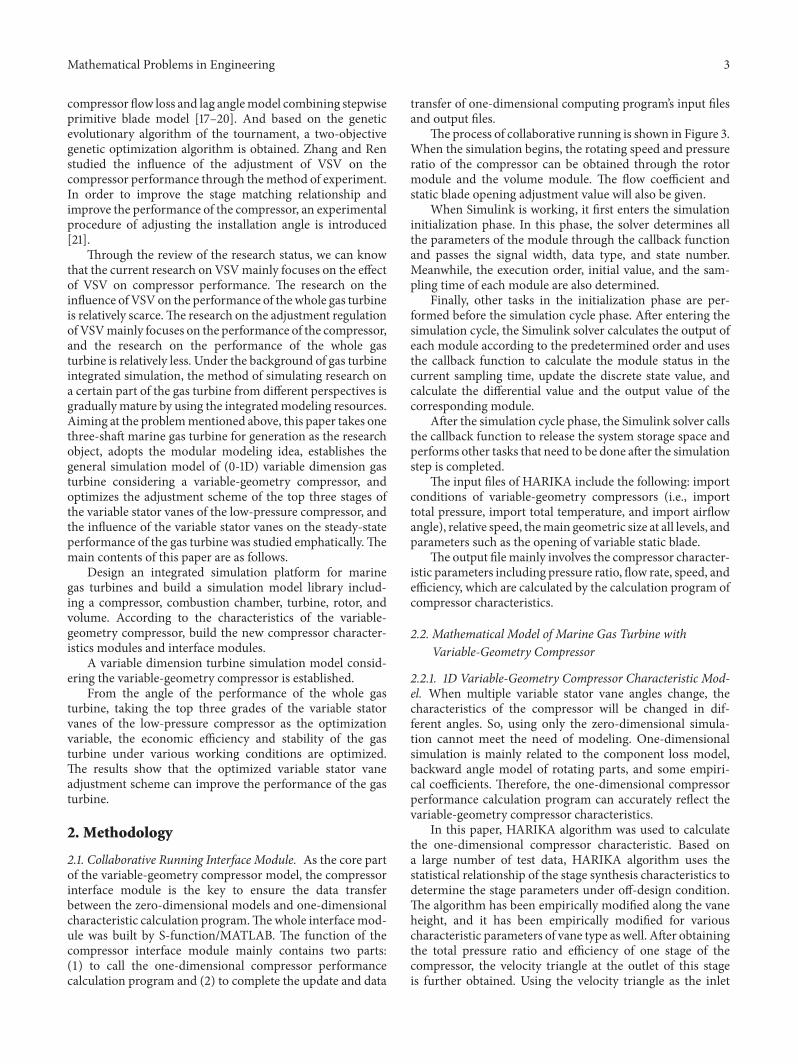
The process of collaborative running is shown in Figure 3.When the simulation begins, the rotating speed and pressureratio of the compressor can be obtained through the rotormodule and the volume module. The flow coefficient andstatic blade opening adjustment value will also be given.
When Simulink is working, it first enters the simulationinitialization phase. In this phase, the solver determines allthe parameters of the module through the callback functionand passes the signal width, data type, and state number.Meanwhile, the execution order, initial value, and the sam-pling time of each module are also determined.
Finally, other tasks in the initialization phase are per-formed before the simulation cycle phase. After entering thesimulation cycle, the Simulink solver calculates the output ofeach module according to the predetermined order and usesthe callback function to calculate the module status in thecurrent sampling time, update the discrete state value, andcalculate the differential value and the output value of thecorresponding module.
After the simulation cycle phase, the Simulink solver callsthe callback function to release the system storage space andperforms other tasks that need to be done after the simulationstep is completed.
The input files of HARIKA include the following: importconditions of variable-geometry compressors (i.e., importtotal pressure, import total temperature, and import airflowangle), relative speed, themain geometric size at all levels, andparameters such as the opening of variable static blade.
The output file mainly involves the compressor character-istic parameters including pressure ratio, flow rate, speed, andefficiency, which are calculated by the calculation program ofcompressor characteristics.
2.2. Mathematical Model of Marine Gas Turbine withVariable-Geometry Compressor
2.2.1. 1D Variable-Geometry Compressor Characteristic Mod-el. When multiple variable stator vane angles change, thecharacteristics of the compressor will be changed in dif-ferent angles. So, using only the zero-dimensional simula-tion cannot meet the need of modeling. One-dimensionalsimulation is mainly related to the component loss model,backward angle model of rotating parts, and some empiri-cal coefficients. Therefore, the one-dimensional compressorperformance calculation program can accurately reflect thevariable-geometry compressor characteristics.
In this paper, HARIKA algorithm was used to calculatethe one-dimensional compressor characteristic. Based ona large number of test data, HARIKA algorithm uses thestatistical relationship of the stage synthesis characteristics todetermine the stage parameters under off-design condition.The algorithm has been empirically modified along the vaneheight, and it has been empirically modified for variouscharacteristic parameters of vane type as well. After obtainingthe total pressure ratio and efficiency of one stage of thecompressor, the velocity triangle at the outlet of this stageis further obtained. Using the velocity triangle as the inlet
4 Mathematical Problems in Engineering
mulOutputs()
mdlInitializeSizes()
De�ne basic attributes of module
Get the low-pressure compressorpressure ratio, speed, and so on
Get the angle of low-pressurecompressor variable blades
Get the low-pressure compressorratio, speed, and other parameters
Modify the relevant parameters andrewrite the input text �le
Start the HARIKA
HARIKA process end?
Read and process the data in output text�le
Get the simulation result throughinterpolation
MelTerminate()
Release storage space
Start HARIKA program
Read the input text �le
Calculate the data of low-pressurecompressor characteristic
Iterative condition met?
Save the calculated results in the outputtext �le
Save the output text �le
Share the datein the text �le
Yes
NoYes
No
Simulink/S-function HARIKA
Stop HARIKA program
Figure 3: The process of collaborative running.
parameter of the next stage of the compressor, the parametersat the outlet of the next stage are obtained by the samemethod. The characteristics of the whole compressor can beobtained by repeating the process. The algorithm is moresuitable as the calculation program of the characteristics ofvariable-geometry compressor components.
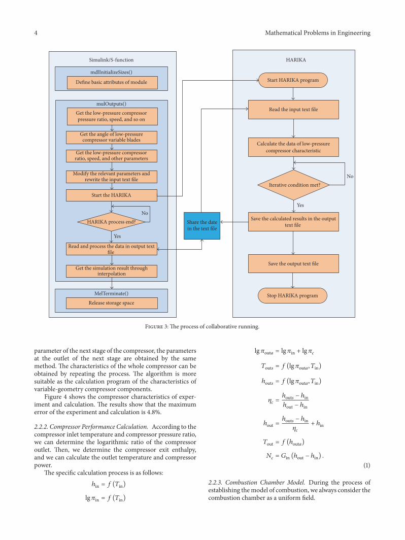
Figure 4 shows the compressor characteristics of exper-iment and calculation. The results show that the maximumerror of the experiment and calculation is 4.8%.
2.2.2. Compressor Performance Calculation. According to thecompressor inlet temperature and compressor pressure ratio,we can determine the logarithmic ratio of the compressoroutlet. Then, we determine the compressor exit enthalpy,and we can calculate the outlet temperature and compressorpower.
The specific calculation process is as follows:ℎin = 𝑓 (𝑇in)
lg𝜋in = 𝑓 (𝑇in)
lg𝜋out𝑎 = lg𝜋in + lg𝜋𝑐𝑇out𝑠 = 𝑓 (lg𝜋out𝑎, 𝑇in)ℎout𝑠 = 𝑓 (lg𝜋out𝑎, 𝑇in)
𝜂𝑐 = ℎout𝑠 − ℎinℎout − ℎinℎout = ℎout𝑠 − ℎin𝜂𝑐 + ℎin𝑇out = 𝑓 (ℎout𝑎)𝑁𝑐 = 𝐺in (ℎout − ℎin) .
(1)
2.2.3. Combustion Chamber Model. During the process ofestablishing themodel of combustion, we always consider thecombustion chamber as a uniform field.
Mathematical Problems in Engineering 5
0.4 0.5 0.6 0.7 0.8 0.90.2
0.3
0.4
0.5
0.6
0.7
0.8
0.9
Experimental dataCalculation results
75007000
6000
Relative inlet mass �ow
6500Relat
ive p
ress
ure r
atio
Figure 4: The compressor characteristics of experiment and calcu-lation.
𝑑𝑃𝑏out𝑑𝑡 = 𝑅𝑔𝑇𝑏out (𝐺𝑏in + 𝐺𝑓 − 𝐺𝑏out)𝑉𝑏 + 𝑃𝑏out𝑇𝑏out
𝑑𝑇𝑏out𝑑𝑡
𝑑𝑇𝑏out𝑑𝑡
= 𝑅𝑔𝑇𝑏out [𝑘 (𝐺𝑏inℎ𝑏in + 𝐺𝑓𝐻𝑢𝜂𝐵 − 𝐺𝑏outℎ𝑏out)]𝑃𝑏out𝑉𝑏𝐶𝑝
− 𝑅𝑔𝑇𝑏outℎ𝑏out (𝐺𝑏in + 𝐺𝑓 − 𝐺𝑏out)𝑃𝑏out𝑉𝑏𝐶𝑝 ,
(2)
𝑃𝑏out for the outlet of the combustion chamber pressureand 𝑇𝑏in and 𝑇𝑏out for inlet and outlet temperature of thecombustion chamber; 𝐺𝑏in, 𝐺𝑏out, and 𝐺𝑓 are the flow at theinlet and outlet of the combustion chamber and fuel injectionquantity; 𝑉𝑏 and 𝑘 are the combustion chamber volume andindex adiabatic of combustion chamber; ℎ𝑏in and ℎ𝑏out are thespecific enthalpy at the inlet and outlet of the combustionchamber; 𝐻𝑢 is the low calorific value of fuel; 𝐶𝑝 is specificheat capacity at constant pressure of the combustion chambervolume.
2.2.4. Turbine Model. The turbine module is similar tothe compressor module, and the mathematical model is asfollows:
𝑛𝑡 = 𝑛𝑡√𝑇𝑡in
𝜋𝑡 = 𝑃𝑡in𝑃𝑡out
𝐺𝑡 = 𝑓 (𝜋𝑡, 𝑛𝑡)𝜂𝑡 = 𝑓 (𝜋𝑡, 𝑛𝑡) ,
(3)
where 𝑇𝑡in is the turbine inlet temperature; 𝑃𝑡in and 𝑃𝑡outare the inlet and outlet turbo pressure; 𝑛𝑡 is the turbine
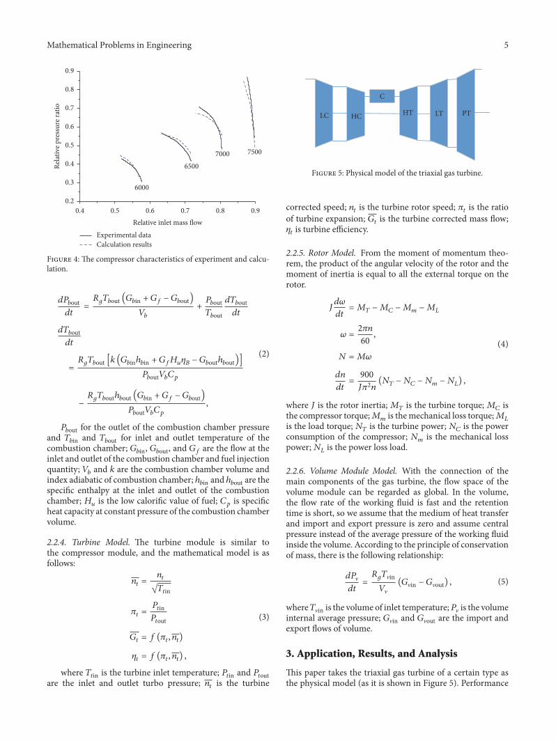
LC HC
C
HT LT PT
Figure 5: Physical model of the triaxial gas turbine.
corrected speed; 𝑛𝑡 is the turbine rotor speed; 𝜋𝑡 is the ratioof turbine expansion; 𝐺𝑡 is the turbine corrected mass flow;𝜂𝑡 is turbine efficiency.
2.2.5. Rotor Model. From the moment of momentum theo-rem, the product of the angular velocity of the rotor and themoment of inertia is equal to all the external torque on therotor.
𝐽𝑑𝜔𝑑𝑡 = 𝑀𝑇 −𝑀𝐶 −𝑀𝑚 −𝑀𝐿𝜔 = 2𝜋𝑛60 ,𝑁 = 𝑀𝜔𝑑𝑛𝑑𝑡 =
900𝐽𝜋2𝑛 (𝑁𝑇 − 𝑁𝐶 − 𝑁𝑚 − 𝑁𝐿) ,
(4)
where 𝐽 is the rotor inertia;𝑀𝑇 is the turbine torque;𝑀𝐶 isthe compressor torque;𝑀𝑚 is themechanical loss torque;𝑀𝐿is the load torque; 𝑁𝑇 is the turbine power; 𝑁𝐶 is the powerconsumption of the compressor; 𝑁𝑚 is the mechanical losspower;𝑁𝐿 is the power loss load.2.2.6. Volume Module Model. With the connection of themain components of the gas turbine, the flow space of thevolume module can be regarded as global. In the volume,the flow rate of the working fluid is fast and the retentiontime is short, so we assume that the medium of heat transferand import and export pressure is zero and assume centralpressure instead of the average pressure of the working fluidinside the volume. According to the principle of conservationof mass, there is the following relationship:
𝑑𝑃V𝑑𝑡 =
𝑅𝑔𝑇Vin𝑉V (𝐺Vin − 𝐺Vout) , (5)
where𝑇Vin is the volume of inlet temperature;𝑃V is the volumeinternal average pressure; 𝐺Vin and 𝐺Vout are the import andexport flows of volume.
3. Application, Results, and Analysis
This paper takes the triaxial gas turbine of a certain type asthe physical model (as it is shown in Figure 5). Performance
6 Mathematical Problems in Engineering
1
lv
Signal 1
Tushuai_50
Load
Load
Gvi
n (k
g/s)
Tvin
(K)
Gvo
ut (k
g/s)
Pv (P
a)
V_LT_PT
Gvi
n (k
g/s)
Tvin
(K)
Gvo
ut (k
g/s)
Pv (P
a)
V_LC_HC
Gvi
n (k
g/s)
Tvin
(K)
Gvo
ut (k
g/s)
Pv (P
a)
V_HT_LT
Nout (kw)
Nin (kw)nr (rpm)
Rotor_PT
Nout (kw)
Nin (kw)nr (rpm)
Rotor_LC_LT
Nout (kw)
Nin (kw)nr (rpm)
Rotor_HC_HT
Ptout (Pa)
GCQ (kg/s)
hCQ (kJ/kg)
Ptin (Pa)
Ttin (K)
�in
Rgtin
nt (rpm)
Gtin (kg/s)
Gtout (kg/s)
Ttout (K)
Mt (Nm)
�out
Rgtout
Nt (kw)
PT_Cp_V
Ptout (Pa)
GCQ (kg/s)
hCQ (kJ/kg)
Ptin (Pa)
Ttin (K)
�in
Rgtin
nt (rpm)
Gtin (kg/s)
Gtout (kg/s)
Ttout (K)
Mt (Nm)
�out
Rgtout
Nt (kw)
LT_Cp_V
-K-LQ
Pcout (Pa)
PFQ (Pa)
Pcin (Pa)
Tcin (K)
nc (rpm)
Gcin (kg/s)
Gcout (kg/s)
hcout (kJ/kg)
Tcout (K)
Nc (kw)
LC_Cp_V
-C-
Hu
Ptout (Pa)
GCQ (kg/s)
hCQ (kJ/kg)
Ptin (Pa)
Ttin (K)
�in
Rgtin
nt (rpm)
Gtin (kg/s)
Gtout (kg/s)
Ttout (K)
Mt (Nm)
�out
Rgtout
Nt (kw)
HT_Cp_V
Pcout (Pa)
PFQ (Pa)
Pcin (Pa)
Tcin (K)
nc (rpm)
Gcin (kg/s)
Gcout (kg/s)
hcout (kJ/kg)
Tcout (K)
Nc (kw)
HC_Cp_V
Gr
npts (rpm)
npt (rpm)
Gf (kg/s)
GT_controller
nLT
G9
nHT
G8
NLc
G7
NHc
G6
npt
G5
-T- G4
-T- G3
-T-
G2
-T-
G1
-T-
G
f(u)
Fcn
-T-F9-T-F8-T-F7
P7
F6
-T-
F5
-T-
F4
-T-
F3
-T-
F2
nHT
F16
nLT
F15
NLc
F14
NHc
F13npt
F12
F11
-T-
F10F1
-T-
F
P1 (Pa)
T1 (K)
Environment
3000
Constant
Gbout (kg/s)
Gbin (kg/s)
hbin (J/kg)
Tbin (K)
Gf (kg/s)
Pbin (Pa)
Pbout (Pa)
Tbout (K)
�out
Rgbout
Combustor_Cp_V
-K-
CQ
8
7
632
1
0
-T-
-T-
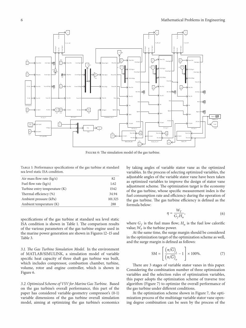
Figure 6: The simulation model of the gas turbine.
Table 1: Performance specifications of the gas turbine at standardsea level static ISA condition.
Air mass flow rate (kg/s) 82Fuel flow rate (kg/s) 1.62Turbine entry temperature (K) 1542Thermal efficiency (%) 34.94Ambient pressure (kPa) 101.325Ambient temperature (K) 288
specifications of the gas turbine at standard sea level staticISA condition is shown in Table 1. The comparison resultsof the various parameters of the gas turbine engine used inthe marine power generation are shown in Figures 12–15 andTable 3.
3.1. The Gas Turbine Simulation Model. In the environmentof MATLAB/SIMULINK, a simulation model of variablespecific heat capacity of three shaft gas turbine was built,which includes compressor, combustion chamber, turbine,volume, rotor and engine controller, which is shown inFigure 6.
3.2. Optimized Scheme of VSV forMarine Gas Turbine. Basedon the gas turbine’s overall performance, this part of thepaper has considered variable-geometry compressor’s (0-1)variable dimensions of the gas turbine overall simulationmodel, aiming at optimizing the gas turbine’s economics
by taking angles of variable stator vane as the optimizedvariables. In the process of selecting optimized variables, theadjustable angles of the variable stator vane have been takenas optimized variables to improve the design of stator vaneadjustment scheme. The optimization target is the economyof the gas turbine, whose specific measurement index is thefuel consumption rate and efficiency during the operation ofthe gas turbine. The gas turbine efficiency is defined as theformula below:
𝜂 = 𝑊𝑇𝐺𝑓𝐻𝑢 , (6)
where 𝐺𝑓 is the fuel mass flow; 𝐻𝑢 is the fuel low calorificvalue;𝑊𝑇 is the turbine power.
At the same time, the surge margin should be consideredin the optimization target of the optimization scheme as well,and the surge margin is defined as follows:
SM = [[(𝜋/𝐺)
𝑠
(𝜋/𝐺)𝑜
− 1]]× 100%. (7)
There are 3 stages of variable stator vanes in this paper.Considering the combination number of three optimizationvariables and the selection rules of optimization variables,this paper adopts the optimization scheme of traverse treealgorithm (Figure 7) to optimize the overall performance ofthe gas turbine under different conditions.
In the optimization scheme shown in Figure 7, the opti-mization process of the multistage variable stator vane open-ing degree combination can be seen by the process of the
Mathematical Problems in Engineering 7
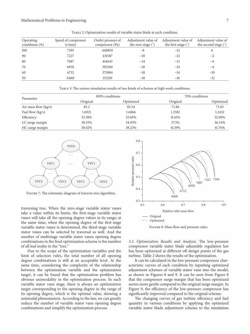
Table 2: Optimization results of variable stator blade at each condition.
Operatingconditions (%)
Speed of compressor(r/min)
Outlet pressure ofcompressor (Pa)
Adjustment value ofthe zero stage (∘)
Adjustment value ofthe first stage (∘)
Adjustment value ofthe second stage (∘)
100 7395 448850 −8 −12 090 7227 431587 −10 −12 −280 7087 414645 −14 −12 −470 6950 395360 −18 −14 −460 6712 375084 −18 −14 −1050 6468 353210 −18 −16 −12
Table 3: The system simulation results of two kinds of schemes at high work conditions.
Parameter 100% conditions 70% conditionsOriginal Optimized Original Optimized
Air mass flow (kg/s) 85.2 85.54 72.86 73.83Fuel flow (kg/s) 1.6921 1.6866 1.2582 1.2432Efficiency 33.58% 33.69% 31.61% 32.00%LC surge margin 38.33% 34.03% 37.3% 36.54%HC surge margin 38.02% 38.23% 41.19% 41.76%
VSV0
VSV1
VSV2
VSV1
VSV2 VSV2 VSV2
· · ·
· · ·
· · ·· · ·
· · ·· · ·
Figure 7: The schematic diagram of traverse tree algorithm.
traversing tree. When the zero-stage variable stator vanestake a value within its limits, the first-stage variable statorvanes will take all the opening degree values in its range; atthe same time, when the opening degree of the first-stagevariable stator vanes is determined, the third-stage variablestator vanes can be selected by traversal as well. And thenumber of multistage variable stator vanes opening degreecombinations in the final optimization scheme is the numberof all leaf nodes in the “tree.”
Due to the scope of the optimization variables and thelimit of selection rules, the total number of all openingdegree combinations is still at an acceptable level. At thesame time, considering the complexity of the relationshipbetween the optimization variable and the optimizationtarget, it can be found that the optimization problem hasobvious unimodality in the optimization process. In eachvariable stator vane stage, there is always an optimizationtarget corresponding to the opening degree in the range ofits opening degree, which is the optimal value, showing aunimodal phenomenon. According to the law, we can greatlyreduce the number of variable stator vane opening degreecombinations and simplify the optimization process.
0.5 0.6 0.7 0.8 0.90.3
0.4
0.5
0.6
0.7
0.8
64686712
7395
6950
7227
Relative inlet mass �owOriginalOptimized
7087Relat
ive p
ress
ure r
atio
Figure 8: Mass flow and pressure ratio.
3.3. Optimization Results and Analysis. The low-pressurecompressor variable stator blade adjustable regulation lawhas been optimized at different off-design points of the gasturbine. Table 2 shows the results of the optimization.
It can be calculated in the low-pressure compressor char-acteristic curves of each condition by inputting optimizedadjustment schemes of variable stator vane into the model,as shown in Figures 8 and 9. It can be seen from Figure 8that the compressor surge margin that has been optimizedseems more gentle compared to the original surge margin. InFigure 9, the efficiency of the low-pressure compressor hassignificantly improved compared to the original scheme.
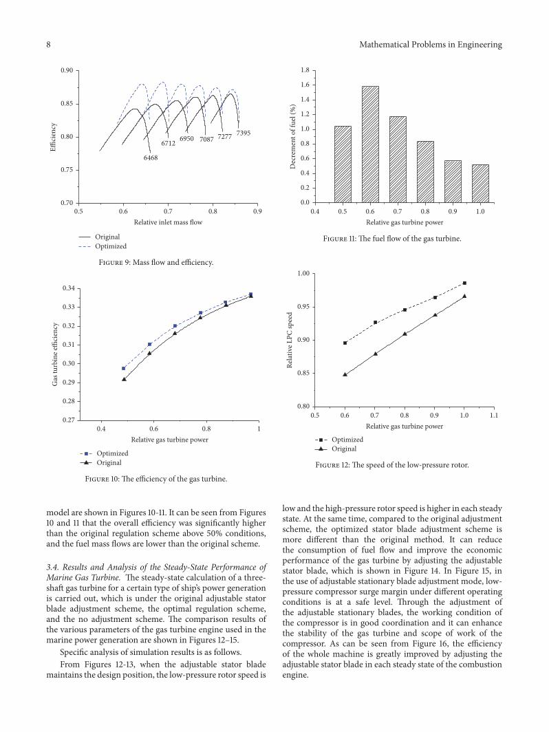
The changing curves of gas turbine efficiency and fuelquantity in various conditions by applying the optimizedvariable stator blade adjustment scheme to the simulation
8 Mathematical Problems in Engineering
0.5 0.6 0.7 0.8 0.90.70
0.75
0.80
0.85
0.90
Original
E�ci
ency
Optimized
7277708769506712
6468
Relative inlet mass �ow
7395
Figure 9: Mass flow and efficiency.
Gas
turb
ine e
�ci
ency
0.27
0.28
0.29
0.30
0.31
0.32
0.33
0.34
10.80.6Relative gas turbine power
OptimizedOriginal
0.4
Figure 10: The efficiency of the gas turbine.
model are shown in Figures 10-11. It can be seen from Figures10 and 11 that the overall efficiency was significantly higherthan the original regulation scheme above 50% conditions,and the fuel mass flows are lower than the original scheme.
3.4. Results and Analysis of the Steady-State Performance ofMarine Gas Turbine. The steady-state calculation of a three-shaft gas turbine for a certain type of ship’s power generationis carried out, which is under the original adjustable statorblade adjustment scheme, the optimal regulation scheme,and the no adjustment scheme. The comparison results ofthe various parameters of the gas turbine engine used in themarine power generation are shown in Figures 12–15.
Specific analysis of simulation results is as follows.From Figures 12-13, when the adjustable stator blade
maintains the design position, the low-pressure rotor speed is
0.4 0.5 0.6 0.7 0.8 0.9 1.00.0
0.2
0.4
0.6
0.8
1.0
1.2
1.4
1.6
1.8
Relative gas turbine power
Dec
rem
ent o
f fue
l (%
)
Figure 11: The fuel flow of the gas turbine.
0.5 0.6 0.7 0.8 0.9 1.0 1.10.80
0.85
0.90
0.95
1.00
Relative gas turbine power
OptimizedOriginal
Rela
tive L
PC sp
eed
Figure 12: The speed of the low-pressure rotor.
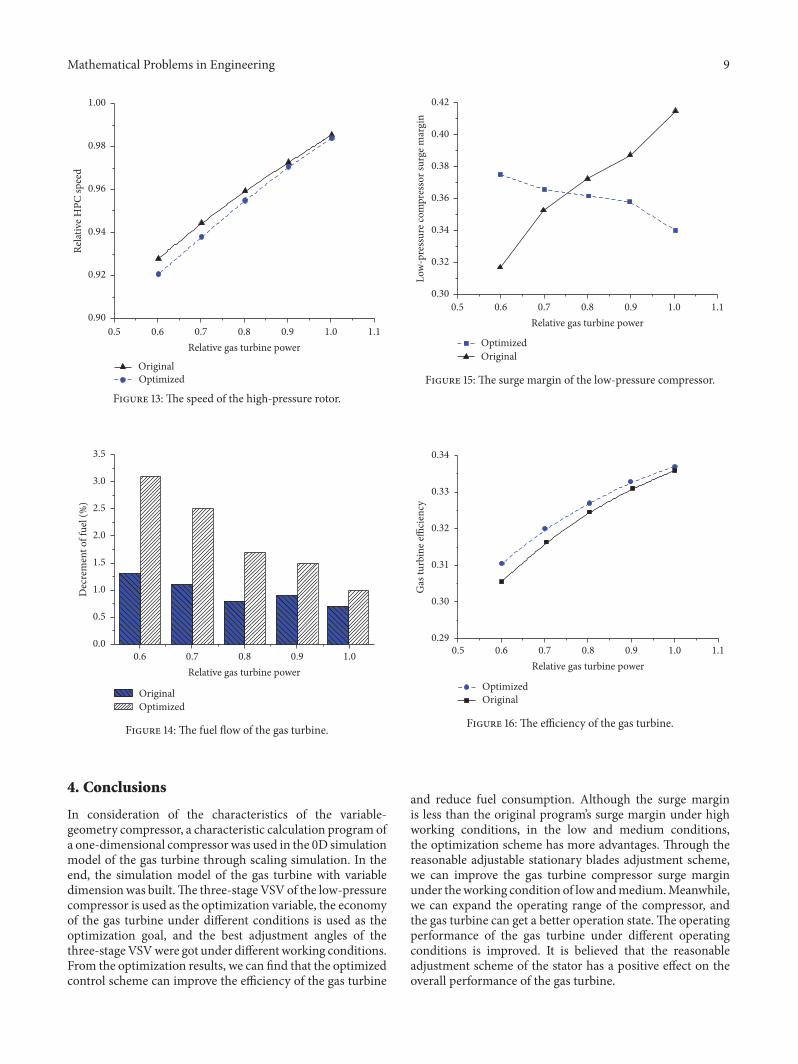
low and the high-pressure rotor speed is higher in each steadystate. At the same time, compared to the original adjustmentscheme, the optimized stator blade adjustment scheme ismore different than the original method. It can reducethe consumption of fuel flow and improve the economicperformance of the gas turbine by adjusting the adjustablestator blade, which is shown in Figure 14. In Figure 15, inthe use of adjustable stationary blade adjustment mode, low-pressure compressor surge margin under different operatingconditions is at a safe level. Through the adjustment ofthe adjustable stationary blades, the working condition ofthe compressor is in good coordination and it can enhancethe stability of the gas turbine and scope of work of thecompressor. As can be seen from Figure 16, the efficiencyof the whole machine is greatly improved by adjusting theadjustable stator blade in each steady state of the combustionengine.
Mathematical Problems in Engineering 9
0.5 0.6 0.7 0.8 0.9 1.0 1.10.90
0.92
0.94
0.96
0.98
1.00
Relative gas turbine power
Rela
tive H
PC sp
eed
OriginalOptimized
Figure 13: The speed of the high-pressure rotor.
0.6 0.7 0.8 0.9 1.00.0
0.5
1.0
1.5
2.0
2.5
3.0
3.5
Relative gas turbine power
OriginalOptimized
Dec
rem
ent o
f fue
l (%
)
Figure 14: The fuel flow of the gas turbine.
4. Conclusions
In consideration of the characteristics of the variable-geometry compressor, a characteristic calculation program ofa one-dimensional compressor was used in the 0D simulationmodel of the gas turbine through scaling simulation. In theend, the simulation model of the gas turbine with variabledimensionwas built.The three-stageVSV of the low-pressurecompressor is used as the optimization variable, the economyof the gas turbine under different conditions is used as theoptimization goal, and the best adjustment angles of thethree-stageVSVwere got under different working conditions.From the optimization results, we can find that the optimizedcontrol scheme can improve the efficiency of the gas turbine
0.5 0.6 0.7 0.8 0.9 1.0 1.10.30
0.32
0.34
0.36
0.38
0.40
0.42
Relative gas turbine power
OptimizedOriginal
Low
-pre
ssur
e com
pres
sor s
urge
mar
gin
Figure 15: The surge margin of the low-pressure compressor.
0.5 0.6 0.7 0.8 0.9 1.0 1.10.29
0.30
0.31
0.32
0.33
0.34
Relative gas turbine power
Gas
turb
ine e
�ci
ency
OptimizedOriginal
Figure 16: The efficiency of the gas turbine.
and reduce fuel consumption. Although the surge marginis less than the original program’s surge margin under highworking conditions, in the low and medium conditions,the optimization scheme has more advantages. Through thereasonable adjustable stationary blades adjustment scheme,we can improve the gas turbine compressor surge marginunder theworking condition of low andmedium.Meanwhile,we can expand the operating range of the compressor, andthe gas turbine can get a better operation state.The operatingperformance of the gas turbine under different operatingconditions is improved. It is believed that the reasonableadjustment scheme of the stator has a positive effect on theoverall performance of the gas turbine.
10 Mathematical Problems in Engineering
Notation
Acronyms
VSV: Variable stator vaneLPC: Low-pressure compressorHPC: High-pressure compressor.
Variables
ℎ: Enthalpy𝑇: Temperature𝑁: Power𝐺: Mass flow𝑃: Pressure𝐶𝑝: Specific heat at constant pressure𝑅𝑔: Gas constant𝐻𝑢: Low calorific value of fuel𝑉: Volume𝐽: Rotor inertia𝑀: Torque𝑊: Power.
Greek Symbols
𝜋: Pressure ratio𝜂: Efficiency𝜅: Index adiabatic of combustion chamber𝜔: Angular speed.
Subscripts
in: Inlet of compressorout: Outlet of compressor𝑐: Compressor𝑠: Isentropy𝑏: Combustionin: Inletout: Outlet𝑡: Turbine𝑓: Fuel𝐿: Load.
Conflicts of Interest
The authors declare that they have no conflicts of interest.
Acknowledgments
The present work is supported by the FundamentalResearch Funds for the Central Universities of China(no. HEUCFM170301).
References
[1] J. Zhang, Model Research of Engine Performance Based onLevel Superposition of Compressor, Beihang University, Beijing,China, 2010.
[2] W. Deng, Research on Simulation Technology of Gas Turbine,Nanjing University of Aeronautics and Astronautics, Nanjing,China, 2012.
[3] D. P. Petters and J. L. Felder, “Engine system performanceof pulse detonation concepts using the NPSS program,” inProceedings of the 38th AIAA/ASME/SAE/ASEE Joint PropulsionConference and Exhibit, July 2002.
[4] R. Sampath, R. Plybon, C. Meyers, R. Irani, and M. Balasubra-maniam, “High fidelity system simulation of aerospace vehiclesusingNPSS,” inProceedings of the 42ndAIAAAerospace SciencesMeeting and Exhibit, AIAA, Reno, Nevada.
[5] M. G. Turner, R. Ryder, J. A. Reed, and J. P. Veres, “Multi-fidelitysimulation of a turbofan engine with results zoomed into mini-maps for a Zero-D cycle simulation,” in Proceedings of the 2004ASME Turbo Expo, pp. 219–230, ASME, Vienna, Austria, June2004.
[6] N. D. Semkin, A. V. Piyakov, K. E. Voronov, N. L. Bogoyavlen-skii, and D. V. Goryunov, “A linear accelerator for simulatingmicrometeorites,” Instruments and Experimental Techniques,vol. 50, no. 2, pp. 275–281, 2007.
[7] M. T. Schobeiri, “Active aerodynamic control of multi-stageaxial compressor instability and surge by dynamically adjustingthe stator blades,” in Proceedings of the ASME Turbo Expo 2001:Power for Land, Sea, and Air, GT 2001, ASME, NewOrleans, La,USA, June 2001.
[8] V. Cyrus, “Aerodynamic performance of an axial compressorstage with variable rotor blades and variable inlet guide vanes,”in Proceedings of the ASME International Gas Turbine and Aero-engine Congress and Exhibition, GT 1998, ASME, Stockholm,Sweden, June 1998.
[9] T. R. Camp and I. J. Day, “A study of spike and modalstall phenomena in a low-speed axial compressor,” Journal ofTurbomachinery, vol. 120, no. 3, pp. 393–401, 1998.
[10] J. E. Roy-Aikins, “Considerations for the use of variable geom-etry in gas turbines,” in Proceedings of the ASME InternationalGas Turbine and Aeroengine Congress and Exposition, ASME,Brussels, Belgium.
[11] C. Celis, P. D. M. R. Pinto, R. S. Barbosa, and S. B. Ferreira,“Modeling of variable inlet guide vanes affects on a one shaftindustrial gas turbine used in a combined cycle application,” inProceedings of the ASME Turbo Expo, pp. 1–6, ASME, Berlin,Germany, June 2008.
[12] A. Wiedermann, D. Frank, U. Orth, and M. Beukenberg,“Computational and experimental analysis of an industrial gasturbine compressor,” in Proceedings of the ASME Turbo Expo:Turbine Technical Conference and Exposition, GT2011, pp. 319–329, ASME, Vancouver, British Columbia, Canada, June 2011.
[13] Y. Hu, Study of DSP Control Technology for Inlet GuideVane/Stator in Multi-stage Axial Compressor [Dissertation, the-sis], School of Chinese Academt of Sciences, China, 2009.
[14] Y. Hu and C. Nie, “Exploration of variable working conditionof guide vane/stator vane/the rotational alignment in axialcompressor,” Chinese Science:Science and Technology, vol. 7, pp.765–771, 2010.
[15] J. F. Klapproth, M. L. Miller, and D. E. Parker, “Aerodynamicdevelopment and performance of the CF6-6/LM2500 compres-sor,” AIAA, 1979, 79-7030.
[16] A. R. Wadia, D. P. Wolf, and F. G. Haaser, “Aerodynamic designand testing of an axial flow compressor with pressure ratio of23.3:1 for the LM2500+ gas turbine,” Journal of Turbomachinery,vol. 124, no. 3, pp. 331–340, 2002.
Mathematical Problems in Engineering 11
[17] W. Hu, M. Kai, and S. Na, “Optimization of variable geoemetryand performance constrains of multistage axial compressor,”Aircraft Engine, vol. 38, article 15706, pp. 11–15, 2012.
[18] W. Hu, “Multi objective optimization of multi stage axialcompressor with variable geometry,” Journal of EngineeringThermal Physics, vol. 3512, pp. 2363–2366, 2014.
[19] W. Hu and S. Na, “Optimization analysis of multi blade rowadjustment and expansion of multi stage axial compressor,”Mechanics and Practice, vol. 3202, pp. 26–31, 2010.
[20] W. Hu and S. Na, “Sun Na.Research on variable geometryoptimization method of multi stage axial compressor,” Journalof Aerospace Power, vol. 2411, pp. 2558–2563, 2009.
[21] J. Zhang and M. Ren, “Experimental study on the influenceof static blade angle on compressor performance,” Journal ofAerospace Power, vol. 1, pp. 27–30, 2000.

Submit your manuscripts athttps://www.hindawi.com
Hindawi Publishing Corporationhttp://www.hindawi.com Volume 2014
MathematicsJournal of
Hindawi Publishing Corporationhttp://www.hindawi.com Volume 2014
Mathematical Problems in Engineering
Hindawi Publishing Corporationhttp://www.hindawi.com
Differential EquationsInternational Journal of
Volume 2014
Applied MathematicsJournal of
Hindawi Publishing Corporationhttp://www.hindawi.com Volume 2014
Probability and StatisticsHindawi Publishing Corporationhttp://www.hindawi.com Volume 2014
Journal of
Hindawi Publishing Corporationhttp://www.hindawi.com Volume 2014
Mathematical PhysicsAdvances in
Complex AnalysisJournal of
Hindawi Publishing Corporationhttp://www.hindawi.com Volume 2014
OptimizationJournal of
Hindawi Publishing Corporationhttp://www.hindawi.com Volume 2014
CombinatoricsHindawi Publishing Corporationhttp://www.hindawi.com Volume 2014
International Journal of
Hindawi Publishing Corporationhttp://www.hindawi.com Volume 2014
Operations ResearchAdvances in
Journal of
Hindawi Publishing Corporationhttp://www.hindawi.com Volume 2014
Function Spaces
Abstract and Applied AnalysisHindawi Publishing Corporationhttp://www.hindawi.com Volume 2014
International Journal of Mathematics and Mathematical Sciences
Hindawi Publishing Corporationhttp://www.hindawi.com Volume 201
The Scientific World JournalHindawi Publishing Corporation http://www.hindawi.com Volume 2014
Hindawi Publishing Corporationhttp://www.hindawi.com Volume 2014
Algebra
Discrete Dynamics in Nature and Society
Hindawi Publishing Corporationhttp://www.hindawi.com Volume 2014
Hindawi Publishing Corporationhttp://www.hindawi.com Volume 2014
Decision SciencesAdvances in
Journal of
Hindawi Publishing Corporationhttp://www.hindawi.com
Volume 2014 Hindawi Publishing Corporationhttp://www.hindawi.com Volume 2014
Stochastic AnalysisInternational Journal of