Embed Size (px)
Citation preview


The outdoor section
Now that we’ve checked our thermostat and air handler, we’re ready to check the outdoor unit.
• Setting the outdoor unit on the shipped with ISO pads, will help reduce sound transmission through the ground.
• The concrete pad should not be touching the structure, for this same reason.
• The unit should be set to prevent air re-circulation across it’s coil. See the installation instructions for that unit.
The outdoor section

HEAT PUMP
REVERSING VALUE
ILLUSTRATION
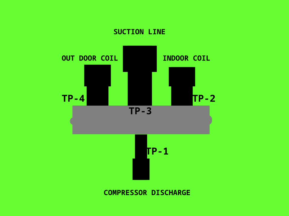
.TP-4 .TP-3
. TP-2
.TP-1
SUCTION LINE
INDOOR COILOUT DOOR COIL
COMPRESSOR DISCHARGE
. . .
.
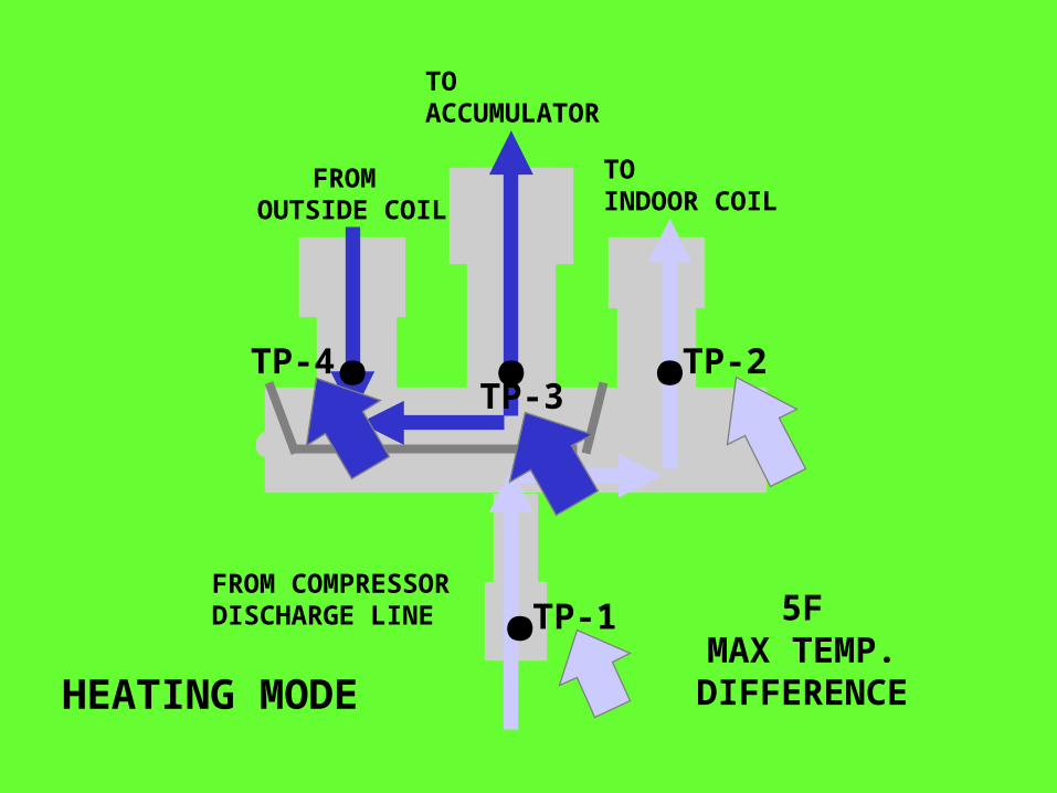
FROM OUTSIDE COIL
TO ACCUMULATOR
TOINDOOR COIL
TP-4TP-3
TP-2
TP-1FROM COMPRESSORDISCHARGE LINE
HEATING MODE
5FMAX TEMP.
DIFFERENCE
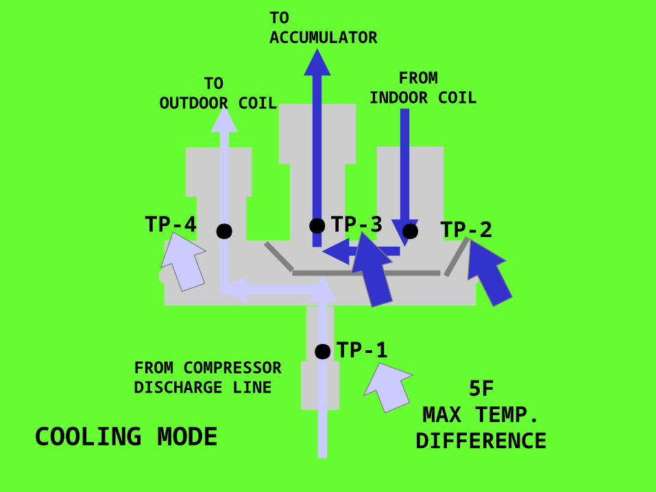
..TP-4 . TP-2
.
... TP-1
. .. TP-3
TO OUTDOOR COIL
TO ACCUMULATOR
FROM INDOOR COIL
FROM COMPRESSOR DISCHARGE LINE
COOLING MODE
5FMAX TEMP.
DIFFERENCE
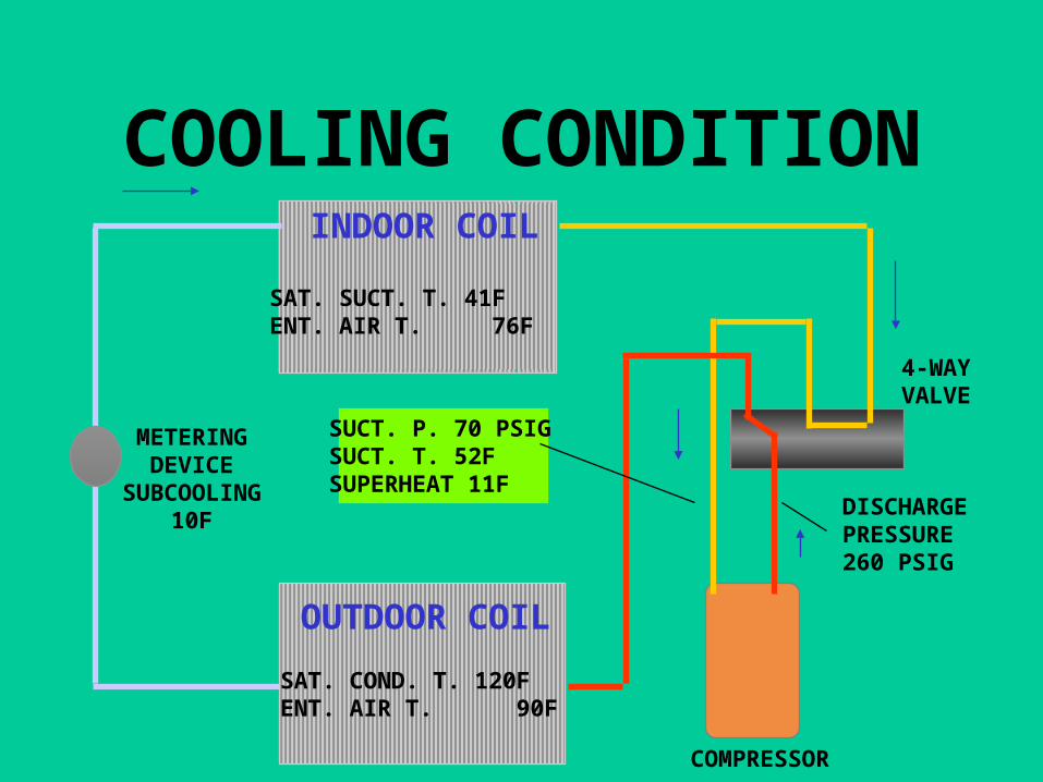
COOLING CONDITIONINDOOR COIL
SAT. SUCT. T. 41FENT. AIR T. 76F
OUTDOOR COIL
SAT. COND. T. 120FENT. AIR T. 90F
4-WAYVALVE
SUCT. P. 70 PSIGSUCT. T. 52FSUPERHEAT 11F
DISCHARGEPRESSURE 260 PSIG
METERINGDEVICE
SUBCOOLING10F
COMPRESSOR
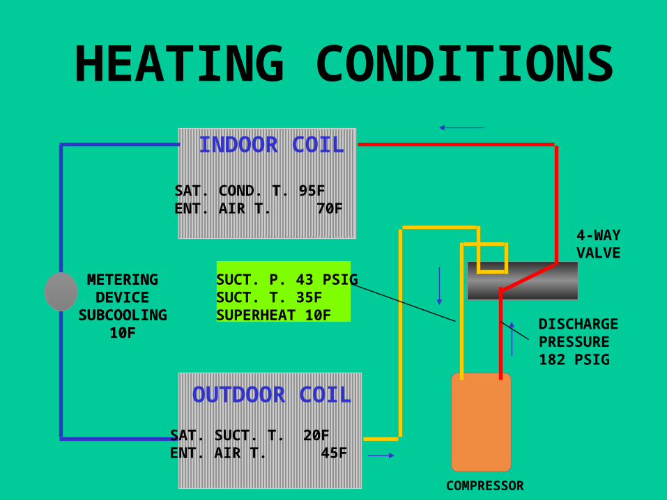
HEATING CONDITIONS
INDOOR COIL
OUTDOOR COIL
METERINGDEVICE
SUBCOOLING10F
SAT. COND. T. 95FENT. AIR T. 70F
SAT. SUCT. T. 20FENT. AIR T. 45F
4-WAYVALVE
DISCHARGEPRESSURE 182 PSIG
METERINGDEVICE
SUBCOOLING10F
SUCT. P. 43 PSIGSUCT. T. 35FSUPERHEAT 10F
COMPRESSOR
HEAT PUMP
• TOTAL HEAT REJECTED EQUALS
HEAT ABSORBED + HEAT OF COMPRESSOR
HEAT PUMP
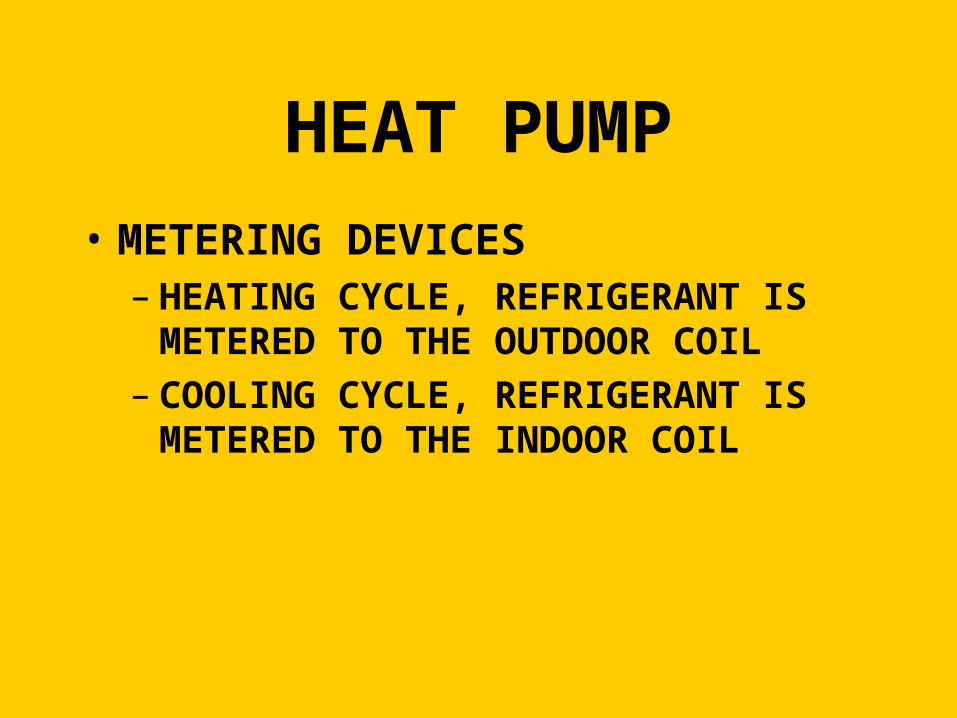
• METERING DEVICES– HEATING CYCLE, REFRIGERANT IS
METERED TO THE OUTDOOR COIL– COOLING CYCLE, REFRIGERANT IS
METERED TO THE INDOOR COIL
HEAT PUMP
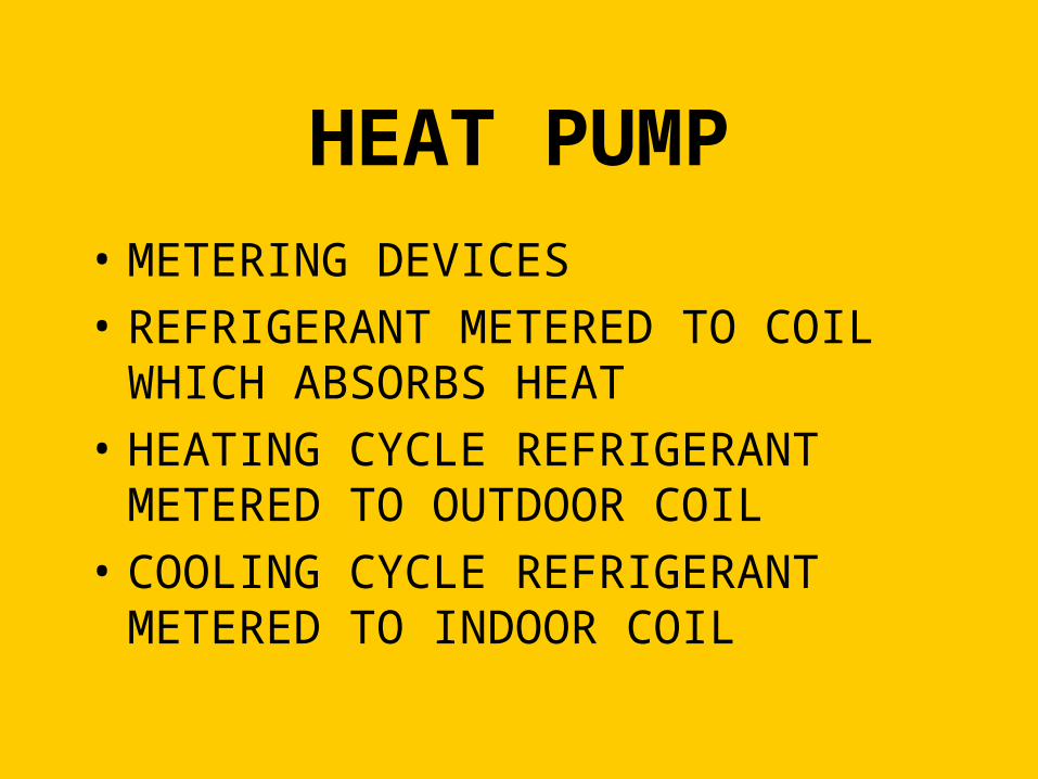
• METERING DEVICES
• REFRIGERANT METERED TO COIL WHICH ABSORBS HEAT
• HEATING CYCLE REFRIGERANT METERED TO OUTDOOR COIL
• COOLING CYCLE REFRIGERANT METERED TO INDOOR COIL
METERING DEVICES
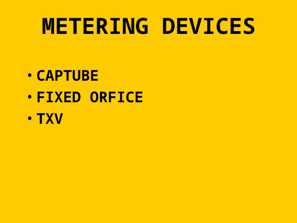
• CAPTUBE
• FIXED ORFICE
• TXV
METERING DEVICES
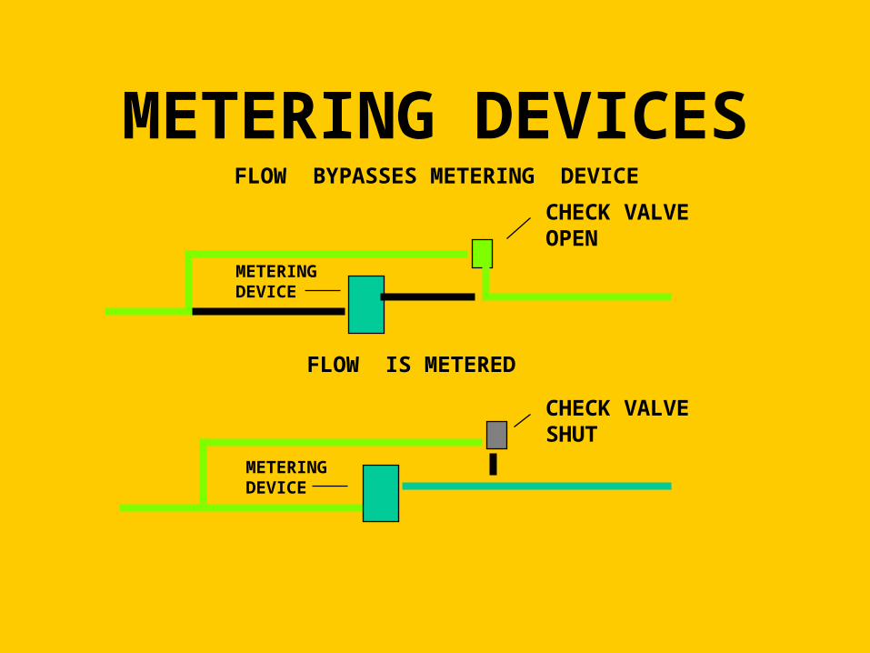
CHECK VALVESHUT
CHECK VALVEOPEN
METERING DEVICE
METERINGDEVICE
FLOW IS METERED
FLOW BYPASSES METERING DEVICE
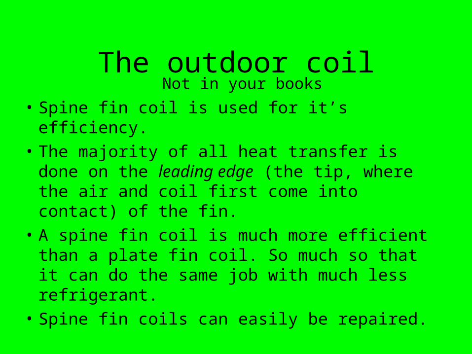
• Spine fin coil is used for it’s efficiency.
• The majority of all heat transfer is done on the leading edge (the tip, where the air and coil first come into contact) of the fin.
• A spine fin coil is much more efficient than a plate fin coil. So much so that it can do the same job with much less refrigerant.
• Spine fin coils can easily be repaired.
Not in your booksThe outdoor coil
The outdoor coil
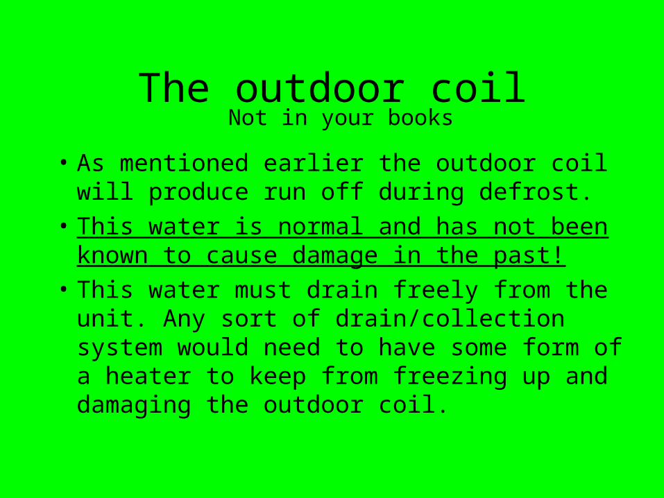
• As mentioned earlier the outdoor coil will produce run off during defrost.
• This water is normal and has not been known to cause damage in the past!
• This water must drain freely from the unit. Any sort of drain/collection system would need to have some form of a heater to keep from freezing up and damaging the outdoor coil.
Not in your books
The role of the defrost control
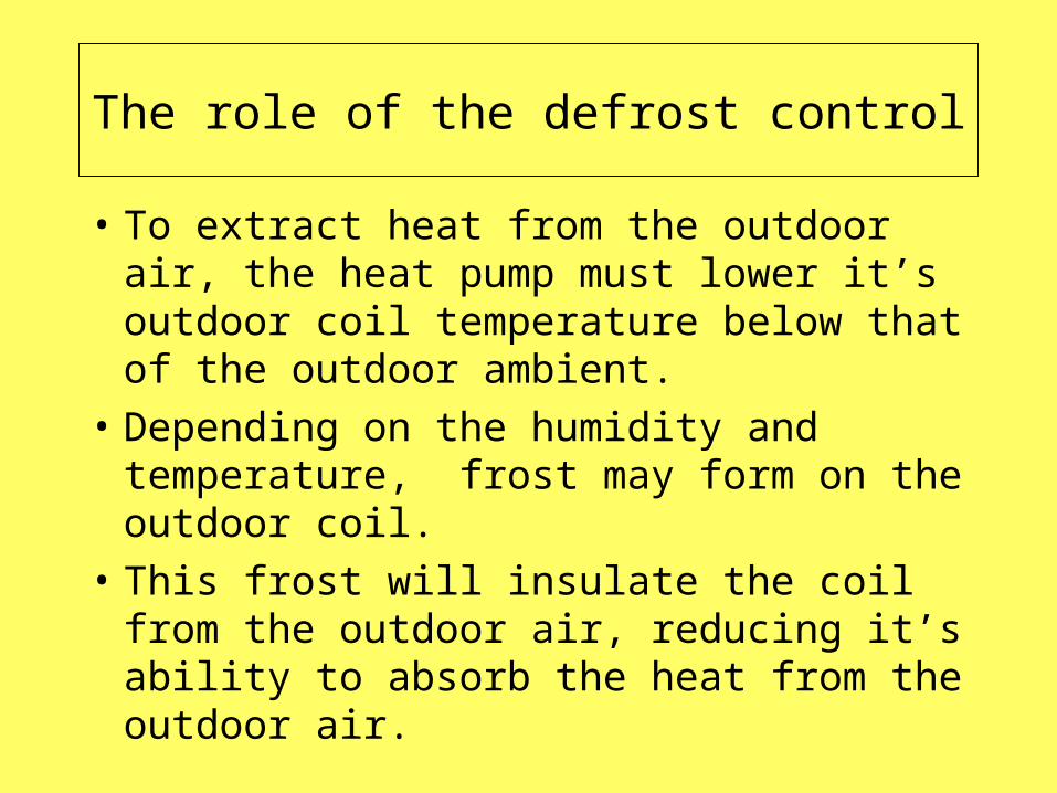
• To extract heat from the outdoor air, the heat pump must lower it’s outdoor coil temperature below that of the outdoor ambient.
• Depending on the humidity and temperature, frost may form on the outdoor coil.
• This frost will insulate the coil from the outdoor air, reducing it’s ability to absorb the heat from the outdoor air.
HEAT PUMP DEFROST CONTROLS
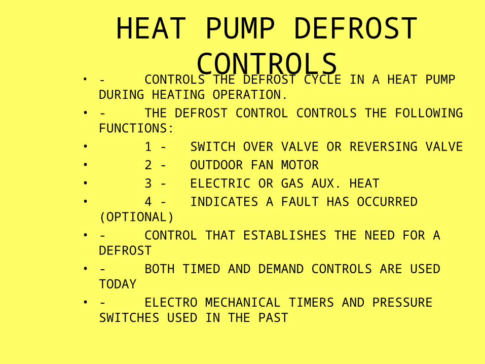
• - CONTROLS THE DEFROST CYCLE IN A HEAT PUMP DURING HEATING OPERATION.
• - THE DEFROST CONTROL CONTROLS THE FOLLOWING FUNCTIONS:
• 1 - SWITCH OVER VALVE OR REVERSING VALVE
• 2 - OUTDOOR FAN MOTOR
• 3 - ELECTRIC OR GAS AUX. HEAT
• 4 - INDICATES A FAULT HAS OCCURRED (OPTIONAL)
• - CONTROL THAT ESTABLISHES THE NEED FOR A DEFROST
• - BOTH TIMED AND DEMAND CONTROLS ARE USED TODAY
• - ELECTRO MECHANICAL TIMERS AND PRESSURE SWITCHES USED IN THE PAST
Heat pump defrost controls
• Several types of defrost controls have been used through the years.
• We will discuss their function and diagnostics of each type.
• The newer solid state and Demand Defrost controls will be the main focus of our time today.
• SYSTEM IN COOLING MODE- -ENERGIZE REVERSING VALVE– DIRECTS HOT GAS TO OUTDOOR COIL
TO MELT THE FROST
DEFROST CYCLE
As the frost accumulates on the outdoor coil, the systems capacity is reduced.
Ö To remove the frost/ice from the outdoor coil, the system will shift itself into a variation of the cooling mode.
Ö During a defrost cycle the outdoor fan will stop, leaving the heat in the coil to remove the frost.
Ö The type of defrost control system will dictate how much frost/ice is allowed to accumulate prior to initiating a defrost.
DEFROST CYCLE
• TEMPERING INDOOR AIR– ELECTRIC HEAT IS TURNED ON TO
TEMPER THE AIR DURING DEFROST CYCLE.
DEFROST CONTROLS
• THE MUCH OLDER EQUIPMENT UTILIZED ELECTRO-MECHANICAL TIME CLOCKS.
• ELECTRONIC TIMER - TIME & TEMPERATURE DEFROST
• SOLID STATE - DEMAND DEFROST
DEFROST CYCLE
• OUTDOOR FAN OFF– ENHANCES DEFROST
Electro-Mechanical systems
ç All electro-mechanical systems are a “time/temperature” based control.
ç A predetermined amount of time must pass before a defrost cycle can be initiated.
ç As mentioned earlier, the outdoor conditions have major impact on the amount of defrost needed.
ç These systems are temperature activated as well.
Large amounts of frost may accumulate before the “Time” has elapsed.
• This results in lower seasonal efficiency.
• The reduced capacity will result with a greater dependence on a secondary heat source.
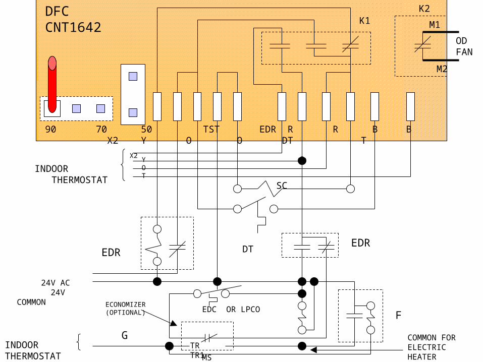
ELECTRONIC TIME-TEMPERATURE DEFROST CONTROL
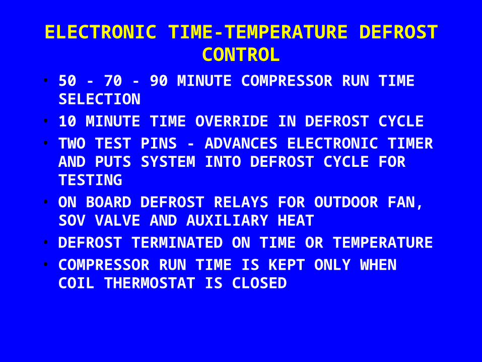
• 50 - 70 - 90 MINUTE COMPRESSOR RUN TIME SELECTION
• 10 MINUTE TIME OVERRIDE IN DEFROST CYCLE• TWO TEST PINS - ADVANCES ELECTRONIC
TIMER AND PUTS SYSTEM INTO DEFROST CYCLE FOR TESTING
• ON BOARD DEFROST RELAYS FOR OUTDOOR FAN, SOV VALVE AND AUXILIARY HEAT
• DEFROST TERMINATED ON TIME OR TEMPERATURE
• COMPRESSOR RUN TIME IS KEPT ONLY WHEN COIL THERMOSTAT IS CLOSED
• The defrost thermostat is set to close at 25º.
• When the DT is closed, supplying 24 VAC to the D terminal, jumpering the test pins will speed up the internal clock.
• If you are testing the system, and have a jumper from R to D, remove the jumper as soon as the system shifts into defrost to prevent excessive refrigerant pressures.
• These controls will default to the 90 minute setting if the selector jumper is not connected. Which is how the equipment is shipped.
• I recommend one of the shorter time settings, 50 or 70 minutes.
• The water run off from a unit in defrost is pure water, and has never been reported to caused roof damage to date!
• Trying to catch the water could damage the outdoor coil (if the collected water froze and backed up under the coil).
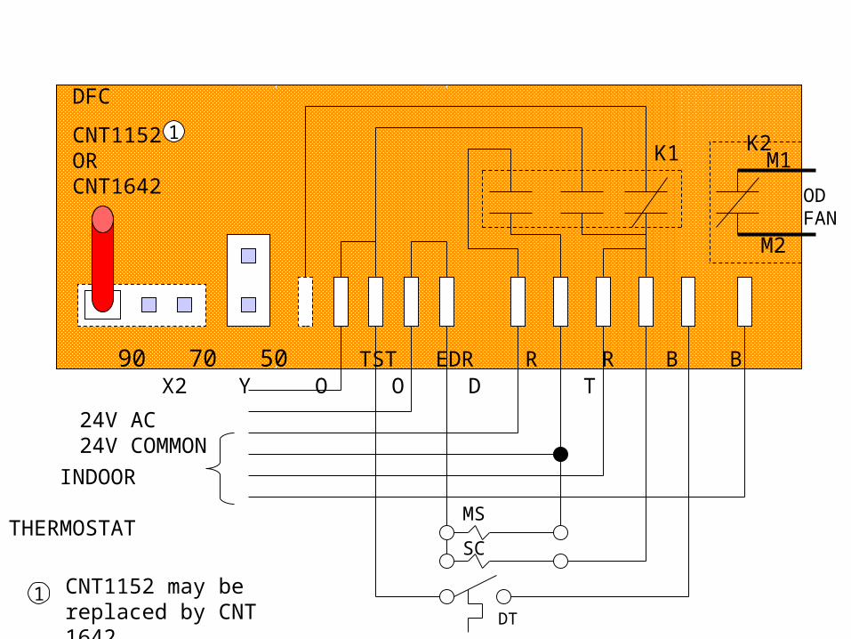
90 70 50 TST EDR R R B B X2 Y O O D T
DFC
CNT1152ORCNT1642
1
CNT1152 may be replaced by CNT 1642
1
K2
M1
M2
ODFAN
K1
24V AC24V COMMON
INDOOR THERMOSTAT
DT
MS
SC
DT
SC
TR TR1
EDC OR LPCO MS
F
G
EDR EDR
DFCCNT1642
K1 K2
M1
M2
ODFAN
90 70 50 TST EDR R R B B X2 Y O O DT T
X2
YOT
INDOOR THERMOSTAT
24V AC 24V COMMON
INDOORTHERMOSTAT
COMMON FORELECTRIC HEATER
ECONOMIZER(OPTIONAL)
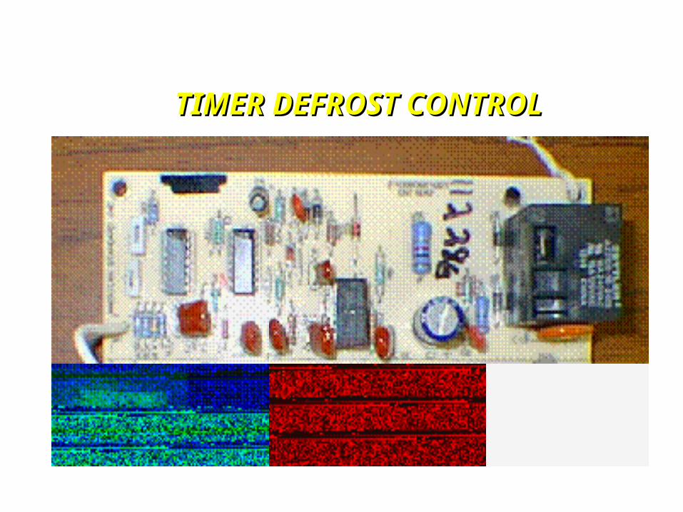
TIMER DEFROST CONTROLTIMER DEFROST CONTROL

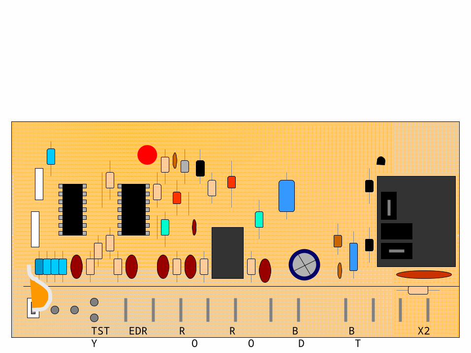
TST EDR R R B B X2 Y O O D T
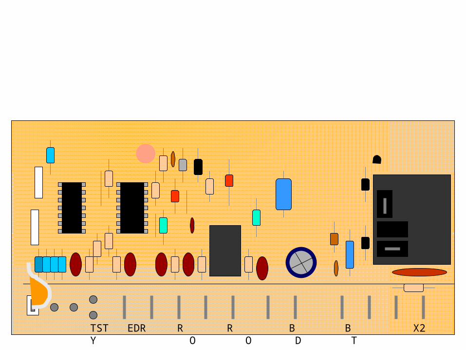
TST EDR R R B B X2 Y O O D T
TST EDR R R B B X2 Y O O D T

TST EDR R R B B X2 Y O O D T

TST EDR R R B B X2 Y O O D T

TST EDR R R B B X2 Y O O D T

TST EDR R R B B X2 Y O O D T

TST EDR R R B B X2 Y O O D T
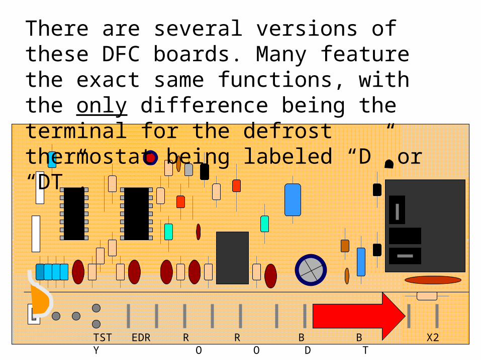
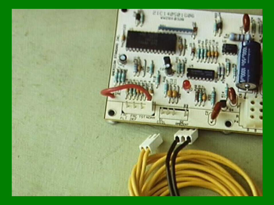
There are several versions of these DFC boards. Many feature the exact same functions, with the only difference being the terminal for the defrost thermostat being labeled “D” or “DT”.

TST EDR R R B B X2 Y O O D T
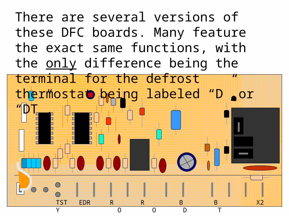
There are several versions of these DFC boards. Many feature the exact same functions, with the only difference being the terminal for the defrost thermostat being labeled “D” or “DT”.
TST EDR R R B B X2 Y O O D T
There are several versions of these DFC boards. Many feature the exact same functions, with the only difference being the terminal for the defrost thermostat being labeled “D” or “DT”.
TST EDR R R B B X2 Y O O D T
There are several versions of these DFC boards. Many feature the exact same functions, with the only difference being the terminal for the defrost thermostat being labeled “D” or “DT”.

TST EDR R R B B X2 Y O O D T
There are several versions of these DFC boards. Many feature the exact same functions, with the only difference being the terminal for the defrost thermostat being labeled “D” or “DT”.

TST EDR R R B B X2 Y O O D T
There are several versions of these DFC boards. Many feature the exact same functions, with the only difference being the terminal for the defrost thermostat being labeled “D” or “DT”.
DEMAND DEFROST
CONTROLS
DEMAND DEFROST
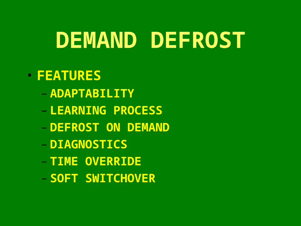
• FEATURES – ADAPTABILITY– LEARNING PROCESS– DEFROST ON DEMAND– DIAGNOSTICS – TIME OVERRIDE– SOFT SWITCHOVER
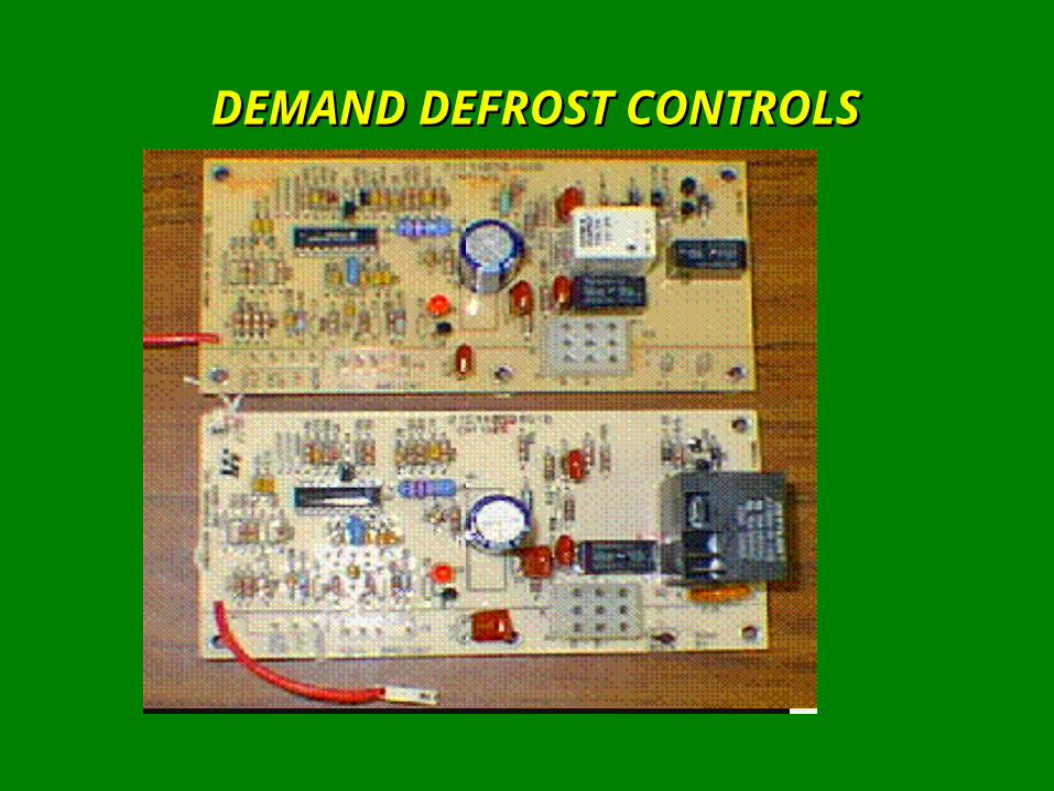
DEMAND DEFROST CONTROLSDEMAND DEFROST CONTROLS
HEAT PUMP DEMAND DEFROST CONTROLS
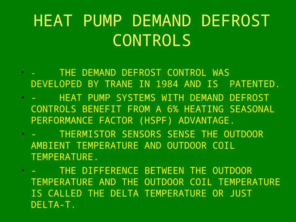
• - THE DEMAND DEFROST CONTROL WAS DEVELOPED BY TRANE IN 1984 AND IS PATENTED.
• - HEAT PUMP SYSTEMS WITH DEMAND DEFROST CONTROLS BENEFIT FROM A 6% HEATING SEASONAL PERFORMANCE FACTOR (HSPF) ADVANTAGE.
• - THERMISTOR SENSORS SENSE THE OUTDOOR AMBIENT TEMPERATURE AND OUTDOOR COIL TEMPERATURE.
• - THE DIFFERENCE BETWEEN THE OUTDOOR TEMPERATURE AND THE OUTDOOR COIL TEMPERATURE IS CALLED THE DELTA TEMPERATURE OR JUST DELTA-T.
HEAT PUMP DEMAND DEFROST CONTROLS
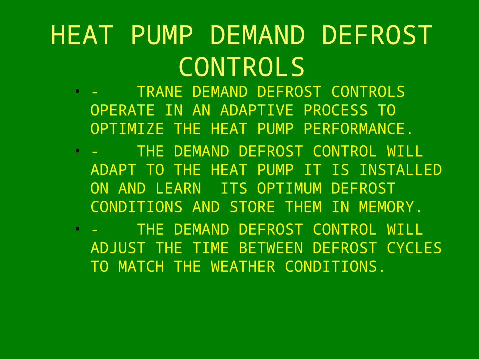
• - TRANE DEMAND DEFROST CONTROLS OPERATE IN AN ADAPTIVE PROCESS TO OPTIMIZE THE HEAT PUMP PERFORMANCE.
• - THE DEMAND DEFROST CONTROL WILL ADAPT TO THE HEAT PUMP IT IS INSTALLED ON AND LEARN ITS OPTIMUM DEFROST CONDITIONS AND STORE THEM IN MEMORY.
• - THE DEMAND DEFROST CONTROL WILL ADJUST THE TIME BETWEEN DEFROST CYCLES TO MATCH THE WEATHER CONDITIONS.
The Defrost Cycle is Initiated • As ice builds on the coil, the delta-t of the system increases
until it reaches the initiate value, and the control starts the defrost process.
• The initiate value is not constant, but instead, is a value that the defrost control has learned will provide a fast, thorough defrost at a given outdoor temperature.
• Low initiate values waste energy by defrosting too often, while high initiate values fail to defrost the coils thoroughly.
• The control is continually varying the initiate value slightly to learn the best value.
• It measures the success of each initiate value by measuring the delta-t of the system during the next heating cycle.
DEFROST IS TERMINATED• Once the temperature of the outdoor coil reaches the
termination value, the defrost control turns on the outdoor fan. After waiting the soft-switch over time, it changes the switch over valve to the heating mode.
• This soft-switch over delay time, 12 seconds, gives the outdoor coil time to cool, reducing the refrigerant pressure and reducing the surge that occurs when the switch over valve is switched.
• If the compressor or “Y” cycles off during defrost, the switchover valve remains energized but the “X2” output will be OFF. If “Y” cycles off during the soft-switchover time, the switchover valve is switched OFF immediately.
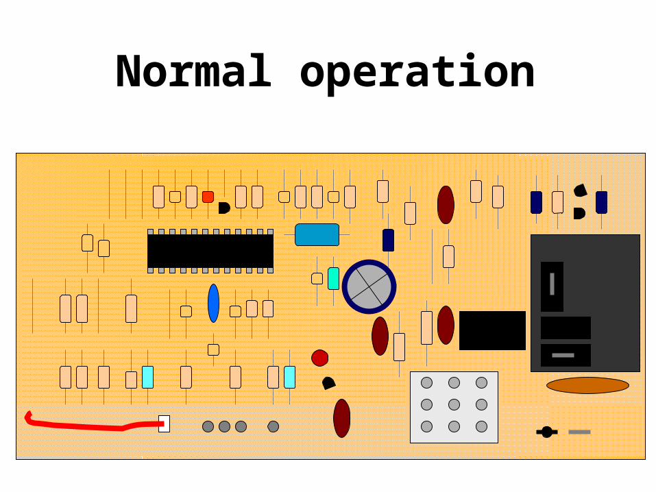
Normal operation


Demand Defrost Control Operation
• Requirements for defrost initialization
• 1 - The outdoor temperature must be less than 52 F
• 2 -The coil temperature must be less than 33 F
• 3 -The Y line must be energized for a least 128 seconds
• 4 -The delta-T must be greater than the initiate temperature
• 5 - It must be time for a timed defrost
• 6 -30 minutes of run time have passed since the unit was first powered up
Demand Defrost Control Operation
• If the unit is placed into a forced defrost by placing the test jumper in the FRC DFT position and Y is energized, none of the above conditions need to be met.
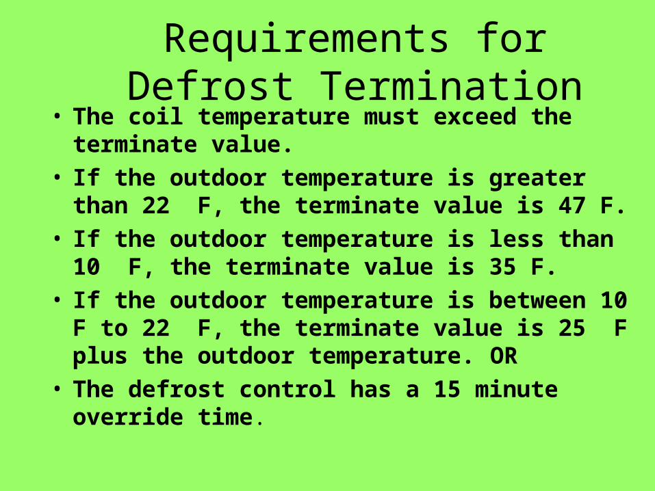
Requirements for Defrost Termination
• The coil temperature must exceed the terminate value.
• If the outdoor temperature is greater than 22 F, the terminate value is 47 F.
• If the outdoor temperature is less than 10 F, the terminate value is 35 F.
• If the outdoor temperature is between 10 F to 22 F, the terminate value is 25 F plus the outdoor temperature. OR
• The defrost control has a 15 minute override time.

The Test Mode• The control may be placed into a test mode
by placing the RED jumper wire on the TST pin.
• This will cause the LED to blink rapidly and the operation of the control will be sped up by a factor of 10.
• The controller will run normally once the jumper is removed from the TST pin.
Fault Indications• There are three types of faults the demand defrost control
can experience.
• All three faults can cause the defrost control to change from a demand defrost control to a timed defrost control which defrosts the unit every 30 minutes.
• When the control goes into a timed defrost mode due to a FAULT A or FAULT C, on units that have the F line feature, it alerts the home owner by energizing the F line once every second which flashes a fault light on the thermostat.
• If the thermostat is switched to the emergency heat position, the F line will be energized, and the defrost control will be cleared of all faults after a few seconds.
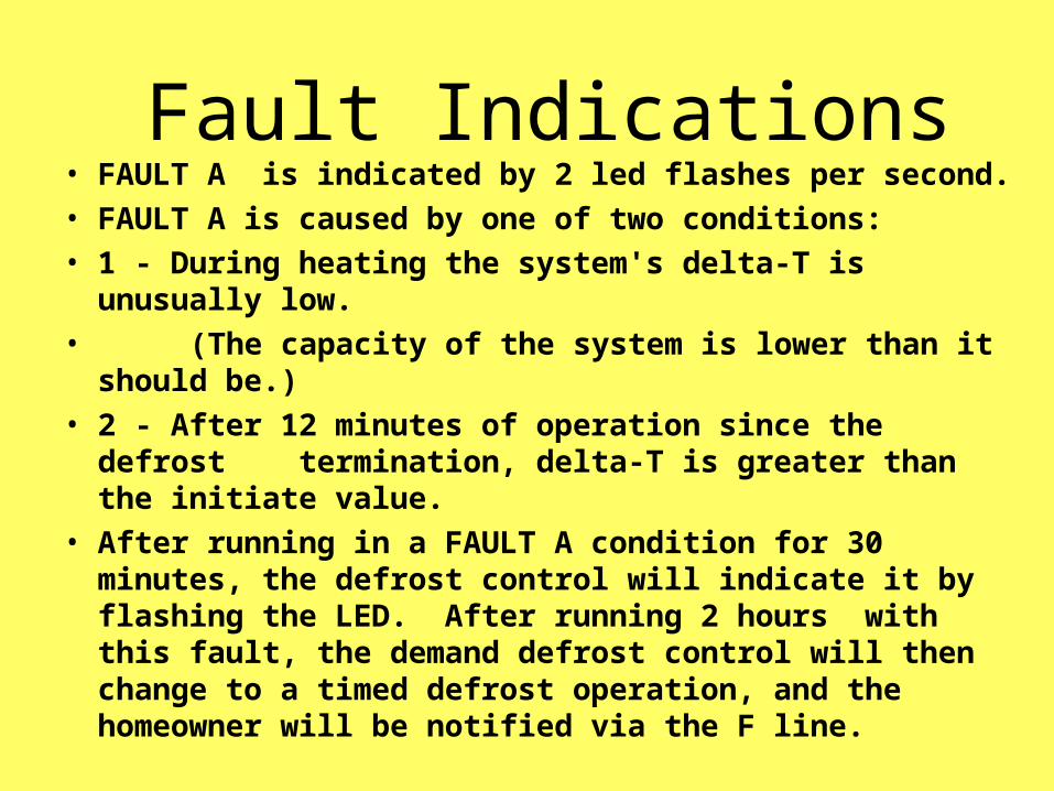
Fault Indications• FAULT A is indicated by 2 led flashes per second.
• FAULT A is caused by one of two conditions:
• 1 - During heating the system's delta-T is unusually low.
• (The capacity of the system is lower than it should be.)
• 2 - After 12 minutes of operation since the defrost termination, delta-T is greater than the initiate value.
• After running in a FAULT A condition for 30 minutes, the defrost control will indicate it by flashing the LED. After running 2 hours with this fault, the demand defrost control will then change to a timed defrost operation, and the homeowner will be notified via the F line.
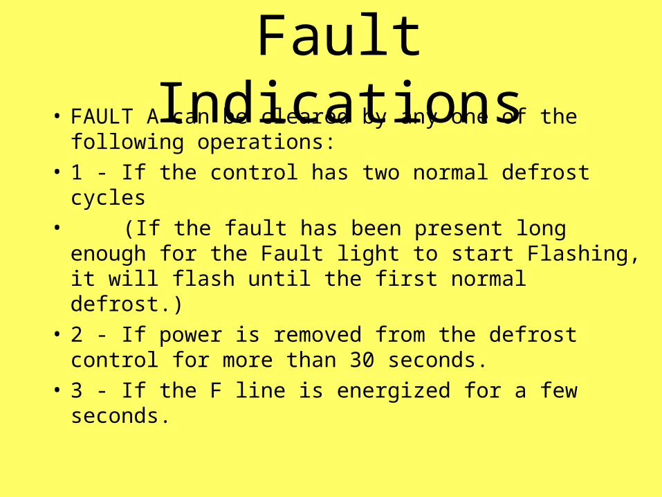
Fault Indications• FAULT A can be cleared by any one of the
following operations:
• 1 - If the control has two normal defrost cycles
• (If the fault has been present long enough for the Fault light to start Flashing, it will flash until the first normal defrost.)
• 2 - If power is removed from the defrost control for more than 30 seconds.
• 3 - If the F line is energized for a few seconds.

Fault A
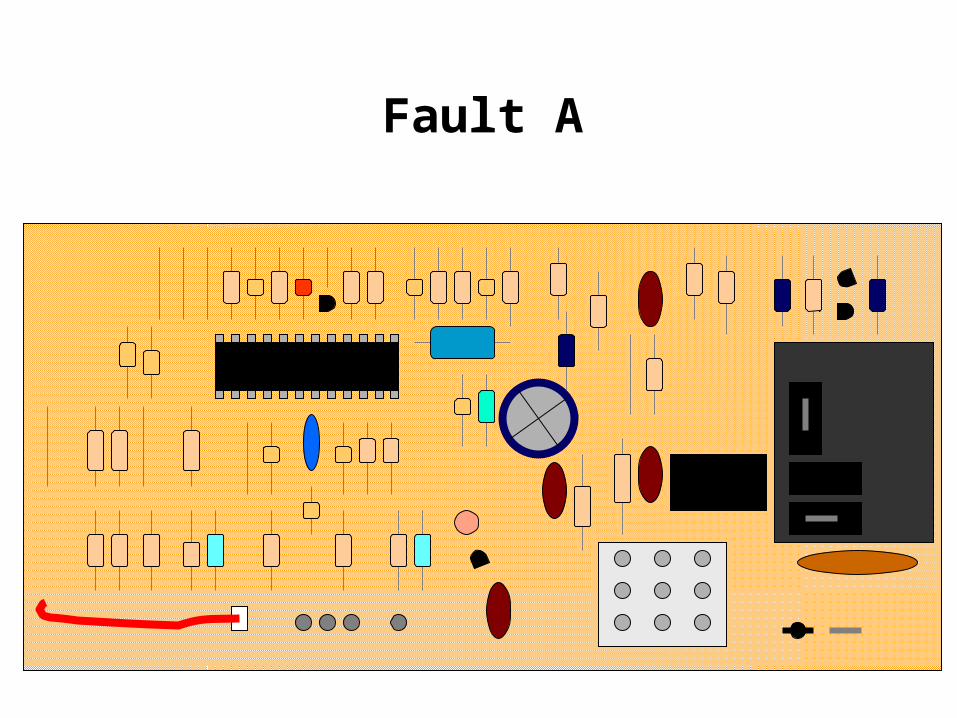
Fault A

Fault A

Fault A

Fault A

Fault A

Fault A

Fault A

Fault A
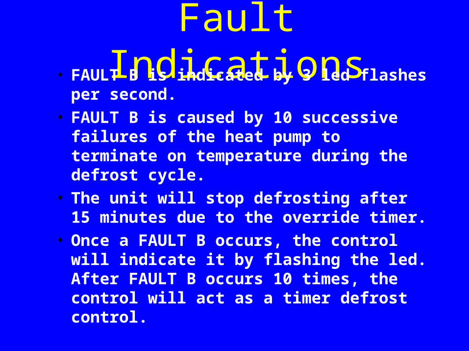
Fault Indications• FAULT B is indicated by 3 led flashes per
second. • FAULT B is caused by 10 successive failures
of the heat pump to terminate on temperature during the defrost cycle.
• The unit will stop defrosting after 15 minutes due to the override timer.
• Once a FAULT B occurs, the control will indicate it by flashing the led. After FAULT B occurs 10 times, the control will act as a timer defrost control.
Fault Indications• FAULT B can be cleared by any one of the
following operations:• 1 - If the control reaches the terminate value
during one of the timed defrost cycles. • (Since this fault is pretty common in cold
climates with high winds, this fault does not alert the home owner via the F line.)
• 2 - If power is removed from the defrost control for more than 30 seconds.
• 3 - If the F line is energized for a few seconds.
Fault Indications• FAULT C is indicated by 3 led flashes per
second.
• FAULT C is caused by 15 successive faults in which the unit has an unusually high delta-T 15 minutes after a defrost termination.
• (Poor air flow over outdoor coils - they are probably blocked by ice.)
Fault Indications• FAULT C can be cleared by any one of the following
operations:• 1 - If the unit has a normal delta-T 15 minutes after a
defrost. (If the fault has been present long enough for the Fault light to start flashing, it will continue to flash until there is a defrost cycle without a high delta-T fault.)
• 2 - If power is removed from the defrost control for more than 30 seconds
• 3 -If the F line is energized for a few seconds

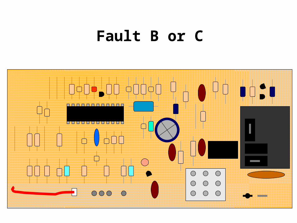
Fault B or C

Fault B or C

Fault B or C

Fault B or C

Fault B or C

Fault B or C

Fault B or C
Fault B or C

Fault B or C

Fault B or C

Fault B or C

Fault B or C

Fault B or C
Combination Fault Indications
• FAULT A & FAULT B, indicated by 4 led flashes per second, is caused by 60 or more FAULT A's occurring and one or more FAULT B's occurring.
• FAULT A & FAULT C, indicated by 4 led flashes per second, is caused by 60 or more FAULT A's occurring and one or more FAULT C's occurring.
• Combination faults will notify the home owner by toggling the F line.
• Combination faults can be cleared by any one of the following operations:
• 1 - If the F line is energized for a few seconds
• 2 - If power is removed from the defrost control for more than 30 seconds
Power-up Initial Defrost• After the defrost board is powered up, its first
defrost cycle will be a timed cycle.• On the newer boards, the unit must run during
defrosting conditions for 30 minutes while some older boards must run for 45 minutes.
• Assuming there are no faults, subsequent defrost cycles will be performed on demand.
• The delay in each case can be reduced to 1/5 this time by placing the red jumper lead on the TST terminal.
Forcing the Unit to Defrost
• Placing the red jumper wire on the FRC DFT pin, the defrost board can be forced to initiate a defrost immediately even if outside temperature conditions are not met.
• The only requirement is that the compressor is running or the “Y” signal is present.
• The defrost will be terminated normally when the outdoor coil becomes hot enough.
• If the jumper is still on the FRC DFT lead upon defrost termination, it will initiate the defrost cycle again.
No Fault Found
• DON’T REPLACE IT!– If LED blinks,– & Sensors ohm out OK,– & Forced defrost works.
• Look Elsewhere For Cause(s)
• Package Unit Ambient Sensor Bracket– Added for better ambient sensing
ODS-A Thermistor Failures
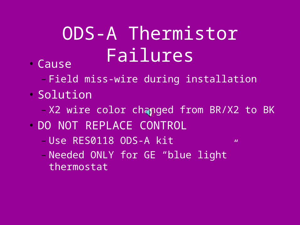
• Cause– Field miss-wire during installation
• Solution– X2 wire color changed from BR/X2 to BK
• DO NOT REPLACE CONTROL– Use RES0118 ODS-A kit– Needed ONLY for GE “blue light” thermostat
Temperature Sensors• The temperature sensors are temperature dependent
resistors encased in a heat-shrunk plastic shroud and sealed from air and moisture by a hot glue adhesive fill.
• The resistance of the sensor decreases as temperature increases according to a specified curve. See the temperature / resistance curve provided with the service information.
• It is rare for a temperature sensor to fail, and most that have been replaced in warranty were OK, or they had been damaged by rough handling.
Temperature Sensors• A common problem with sensors is damage
inflicted by forcing ohmmeter probes into their connectors. This permanently bends the contact causing an intermittent connection.
• On some package units, the sensor leads have been pinched by the access panel. Checking the sensor resistance to ground will detect this problem.
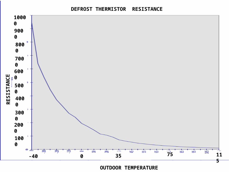
RE
SIS
TA
NC
EDEFROST THERMISTOR RESISTANCE
10000
9000
8000
7000
6000
5000
4000
3000
2000
1000
OUTDOOR TEMPERATURE
-40 0 35 75 115
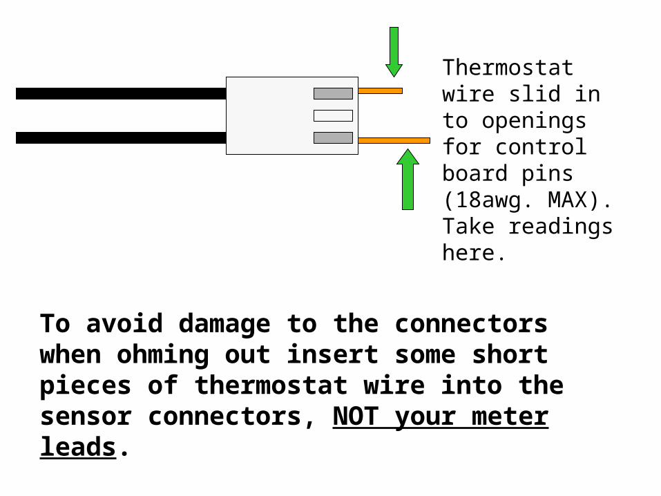
To avoid damage to the connectors when ohming out insert some short pieces of thermostat wire into the sensor connectors, NOT your meter leads.
Thermostat wire slid in to openings for control board pins (18awg. MAX). Take readings here.
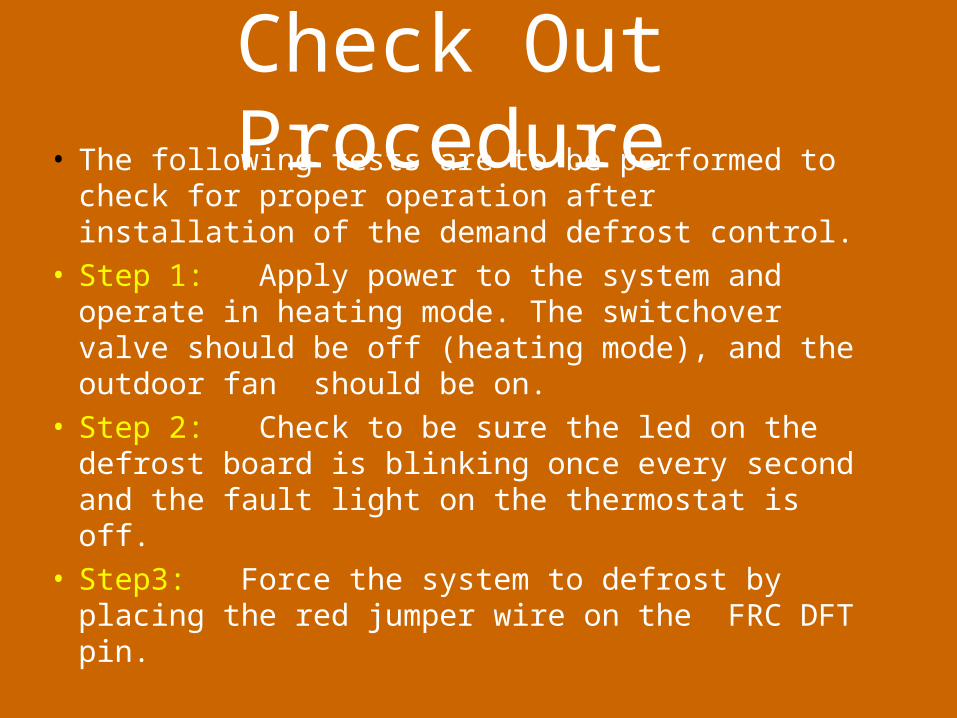
Check Out Procedure• The following tests are to be performed to check for
proper operation after installation of the demand defrost control.
• Step 1: Apply power to the system and operate in heating mode. The switchover valve should be off (heating mode), and the outdoor fan should be on.
• Step 2: Check to be sure the led on the defrost board is blinking once every second and the fault light on the thermostat is off.
• Step3: Force the system to defrost by placing the red jumper wire on the FRC DFT pin.
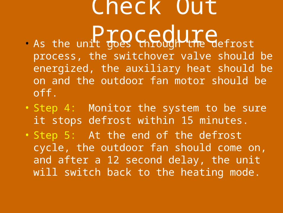
Check Out Procedure• As the unit goes through the defrost process, the
switchover valve should be energized, the auxiliary heat should be on and the outdoor fan motor should be off.
• Step 4: Monitor the system to be sure it stops defrost within 15 minutes.
• Step 5: At the end of the defrost cycle, the outdoor fan should come on, and after a 12 second delay, the unit will switch back to the heating mode.
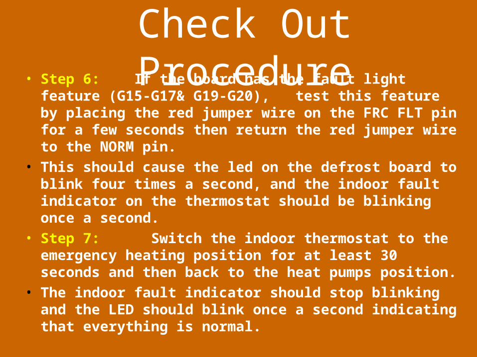
Check Out Procedure• Step 6: If the board has the fault light feature (G15-G17&
G19-G20), test this feature by placing the red jumper wire on the FRC FLT pin for a few seconds then return the red jumper wire to the NORM pin.
• This should cause the led on the defrost board to blink four times a second, and the indoor fault indicator on the thermostat should be blinking once a second.
• Step 7: Switch the indoor thermostat to the emergency heating position for at least 30 seconds and then back to the heat pumps position.
• The indoor fault indicator should stop blinking and the LED should blink once a second indicating that everything is normal.
Helpful Hints in Case of Difficulty
• Led fails to blink on the defrost board
• If the led is off, check between R and B to be sure 24 volts is present.
• Remove power for one minute and re-apply power. Check to see if the LED starts flashing.
Helpful Hints in Case of Difficulty
• LED flashes, but the unit fails the forced defrost test.
• 1. Be sure the red jumper wire was returned to the NORM pin.
• 2. Make sure the thermostat is calling for heating (24 V on Y)
• 3. Verify that the sensors are connected and mounted in the right places
• 4. Check the electrical connections to the defrost board (24V on O while defrosting)
• 5. There is a 1 minute minimum time in defrost under normal operation.
• If defrost is forced there is no minimum time in defrost.
Helpful Hints in Case of Difficulty
• 1- The indoor fault indicator goes on and then goes off.
• During extreme weather conditions, the unit may have difficulty defrosting. This will cause a fault and alert the owner, but when the weather is more temperate, the fault will clear and the indicator will stop blinking.
• 2 - The outdoor sensor (ODS) is burnt on the defrost board.
• Check control wiring “T” and “X2” .
• On the newer units the X2 lead is black and this is not as likely to happen.
• On Equipment with ICM-2 indoor fan motors if unit changes indoor fan speed during defrost, check dip switch 7 & 8 settings.
• If system has supplemental strips installed, X2 is energizing them and the blower is responding to it’s dip switch settings.
Helpful Hints in Case of Difficulty
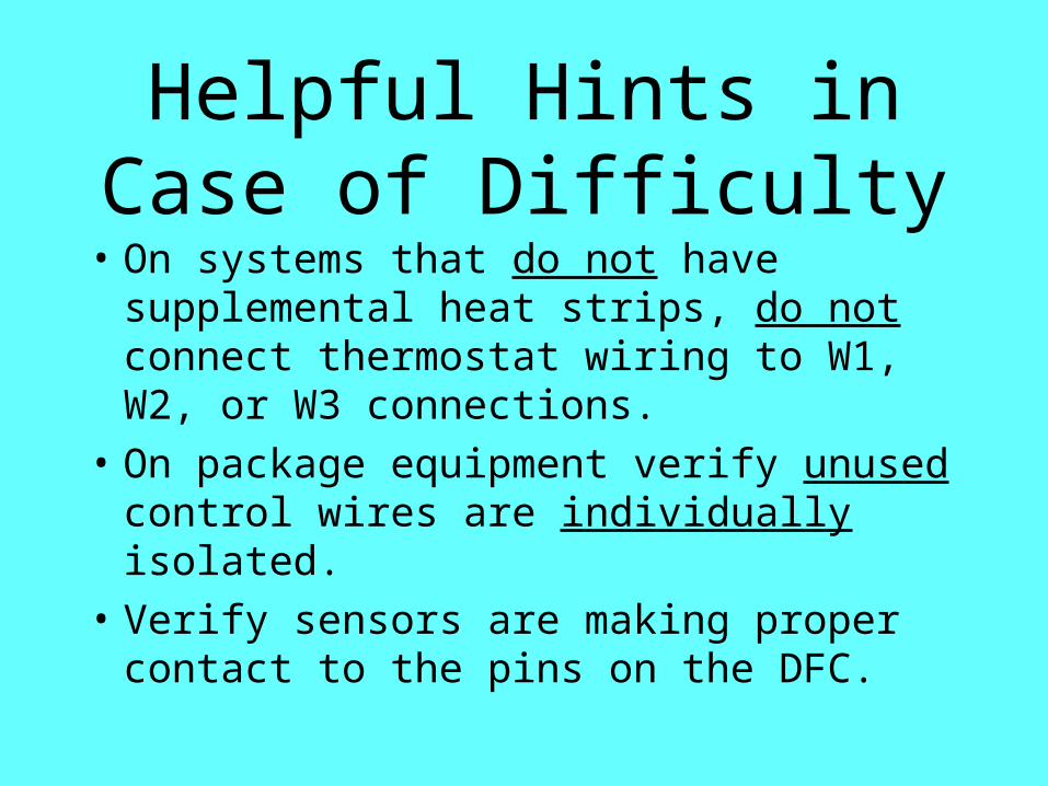
• On systems that do not have supplemental heat strips, do not connect thermostat wiring to W1, W2, or W3 connections.
• On package equipment verify unused control wires are individually isolated.
• Verify sensors are making proper contact to the pins on the DFC.
Helpful Hints in Case of Difficulty
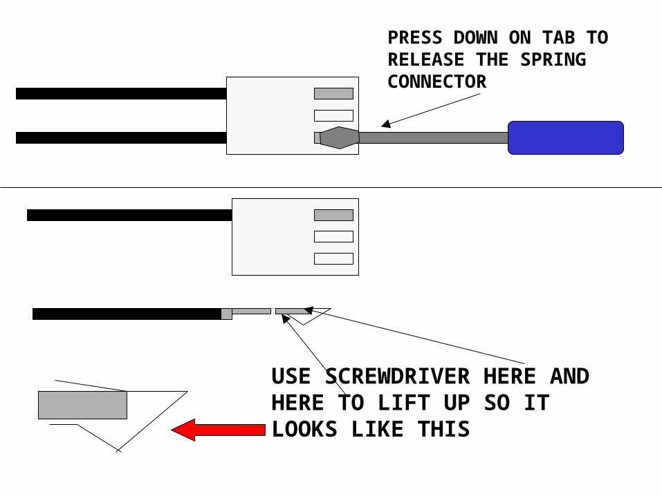
USE SCREWDRIVER HERE AND HERE TO LIFT UP SO IT LOOKS LIKE THIS
PRESS DOWN ON TAB TO RELEASE THE SPRING CONNECTOR
Demand Defrost ControlProblems
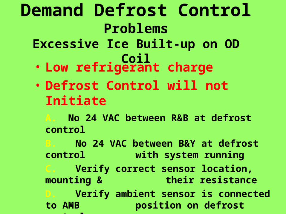
Excessive Ice Built-up on OD Coil• Low refrigerant charge
• Defrost Control will not InitiateA. No 24 VAC between R&B at defrost control
B. No 24 VAC between B&Y at defrost control with system running
C. Verify correct sensor location, mounting & their resistance
D. Verify ambient sensor is connected to AMB position on defrost control
E. Verify coil sensor is connected to coil position on defrost control
Demand Defrost ControlProblems
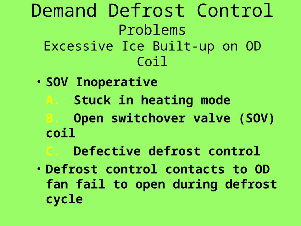
Excessive Ice Built-up on OD Coil
• SOV Inoperative
A. Stuck in heating mode
B. Open switchover valve (SOV) coil
C. Defective defrost control
• Defrost control contacts to OD fan fail to open during defrost cycle
Demand Defrost ControlProblems
Excessive Ice Built-up on OD Coil
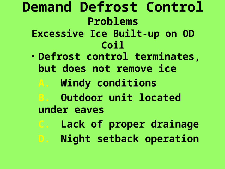
• Defrost control terminates, but does not remove ice
A. Windy conditions
B. Outdoor unit located under eaves
C. Lack of proper drainage
D. Night setback operation
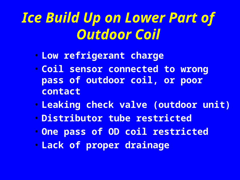
Ice Build Up on Lower Part of Outdoor Coil
• Low refrigerant charge
• Coil sensor connected to wrong pass of outdoor coil, or poor contact
• Leaking check valve (outdoor unit)
• Distributor tube restricted
• One pass of OD coil restricted
• Lack of proper drainage
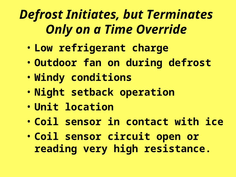
Defrost Initiates, but Terminates Only on a Time Override
• Low refrigerant charge
• Outdoor fan on during defrost
• Windy conditions
• Night setback operation
• Unit location
• Coil sensor in contact with ice
• Coil sensor circuit open or reading very high resistance.
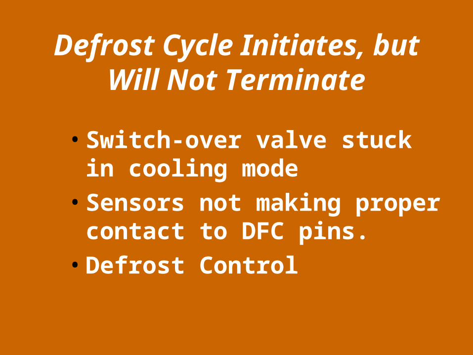
Defrost Cycle Initiates, but Will Not Terminate
• Switch-over valve stuck in cooling mode
• Sensors not making proper contact to DFC pins.
• Defrost Control
Unit Goes Into Defrost In Cooling Mode
• Defective Sensors
• Defective Defrost Control
Control Terminates Defrost Before Frost Is Gone
• Coil sensor mounted in wrong location or has incorrect resistance reading
• Refrigerant overcharge
Defrost Initiates About Every 15 Minutes
• Coil sensor
• Ambient sensor
• Defrost control
Defrost Initiates About Every 30 Minutes. Fault Light on Indoor Thermostat Will Be
Flashing If Wired
• Coil sensor
• Ambient sensor
• Weather conditions
• Night setback operation
• Outdoor fan on during defrost
• System refrigerant charge
• SOV operation
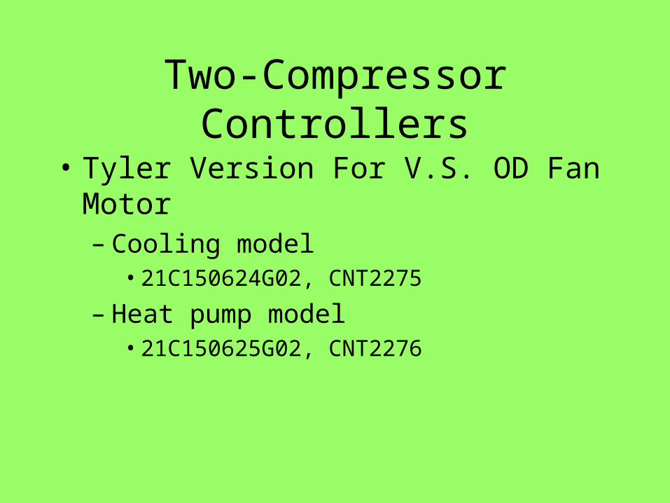
Two-Compressor Controllers
• Tyler Version For V.S. OD Fan Motor– Cooling model
• 21C150624G02, CNT2275
– Heat pump model• 21C150625G02, CNT2276
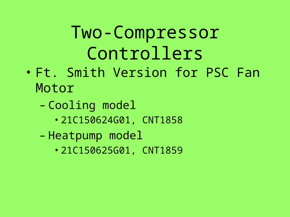
Two-Compressor Controllers
• Ft. Smith Version for PSC Fan Motor– Cooling model
• 21C150624G01, CNT1858
– Heatpump model• 21C150625G01, CNT1859
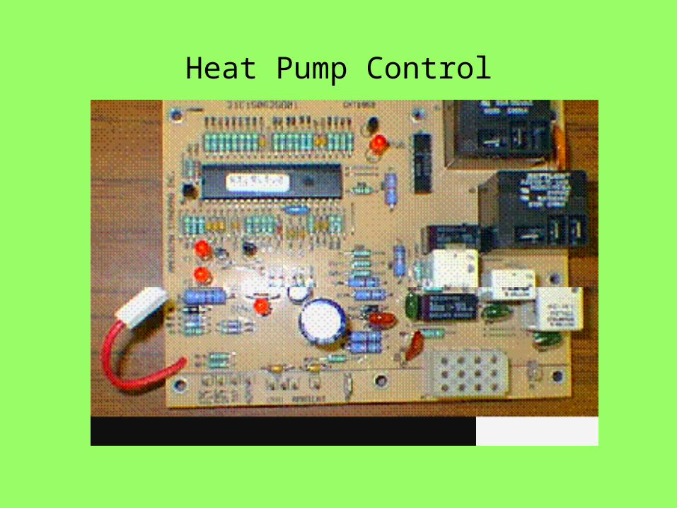
Heat Pump Control