Embed Size (px)
Citation preview
European Heart Journal (2001) 22, 1311–1317doi:10.1053/euhj.2000.2542, available online at http://www.idealibrary.com on
The pattern of restenosis and vascular remodellingafter cold-end radioactive stent implantation
I. P. Kay1, A. J. Wardeh1, K. Kozuma1, G. Sianos1, E. Regar1, M. Knook1,W. J. van der Giessen1, A. Thury1, J. M. R. Ligthart1, V. M. A. Coen2,
P. C. Levendag2 and P. W. Serruys1
From the 1Thoraxcenter and the 2Daniel den Hoed Cancer Center, Rotterdam, The Netherlands
Background Edge restenosis is a major problem afterradioactive stenting. The cold-end stent has a radioactivemid-segment (15·9 mm) and non-radioactive proximal anddistal 5·7 mm segments. Conceptually this may negate theimpact of negative vascular remodelling at the edge of theradiation.
Method and Results ECG-gated intravascular ultrasoundwith three-dimensional reconstruction was performed post-stent implantation and at the 6-month follow-up to assessrestenosis within the margins of the stent and at the stentedges in 16 patients. Angiographic restenosis was witnessedin four patients, all in the proximal in-stent position. Byintravascular ultrasound in-stent neointimal hyperplasia,with a >50% stented cross-sectional area, was seen in eightpatients. This was witnessed proximally (n=2), distally(n=2) and in both segments (n=4). Echolucent tissue,dubbed the ‘black hole’ was seen as a significant componentof neointimal hyperplasia in six out of the eight cases of
0195-668X/01/221311+07 $35.00/0
restenosis. Neointimal hyperplasia was inhibited in the areaof radiation: � neointimal hyperplasia=3·72 mm3 (8·6%);in-stent at the edges of radiation proximally and distally �neointimal hyperplasia was 7·9 mm3 (19·0%) and 11·4 mm3
(25·6%), respectively (P=0·017). At the stent edges therewas no significant change in lumen volume.
Conclusions Cold-end stenting results in increasedneointimal hyperplasia in in-stent non-radioactivesegments.(Eur Heart J 2001; 22: 1311–1317, doi:10.1053/euhj.2000.2542)� 2001 The European Society of Cardiology
Key Words: Stents, remodelling, radioisotopes, angio-plasty, ultrasonics.
See page 1245 for the Editorial comment on this article
Introduction
Conventional stenting has eliminated recoil and negativeremodelling as components of the restenotic process.However, this has been at the cost of exacerbatingneointimal proliferation secondary to chronic vessel wallirritation, leading to in-stent restenosis[1,2].
Intracoronary radiation has been developed in anattempt to decrease restenosis after balloon angioplastyand stent implantation. Studies recently performedin humans demonstrated a dose-dependent inhibition
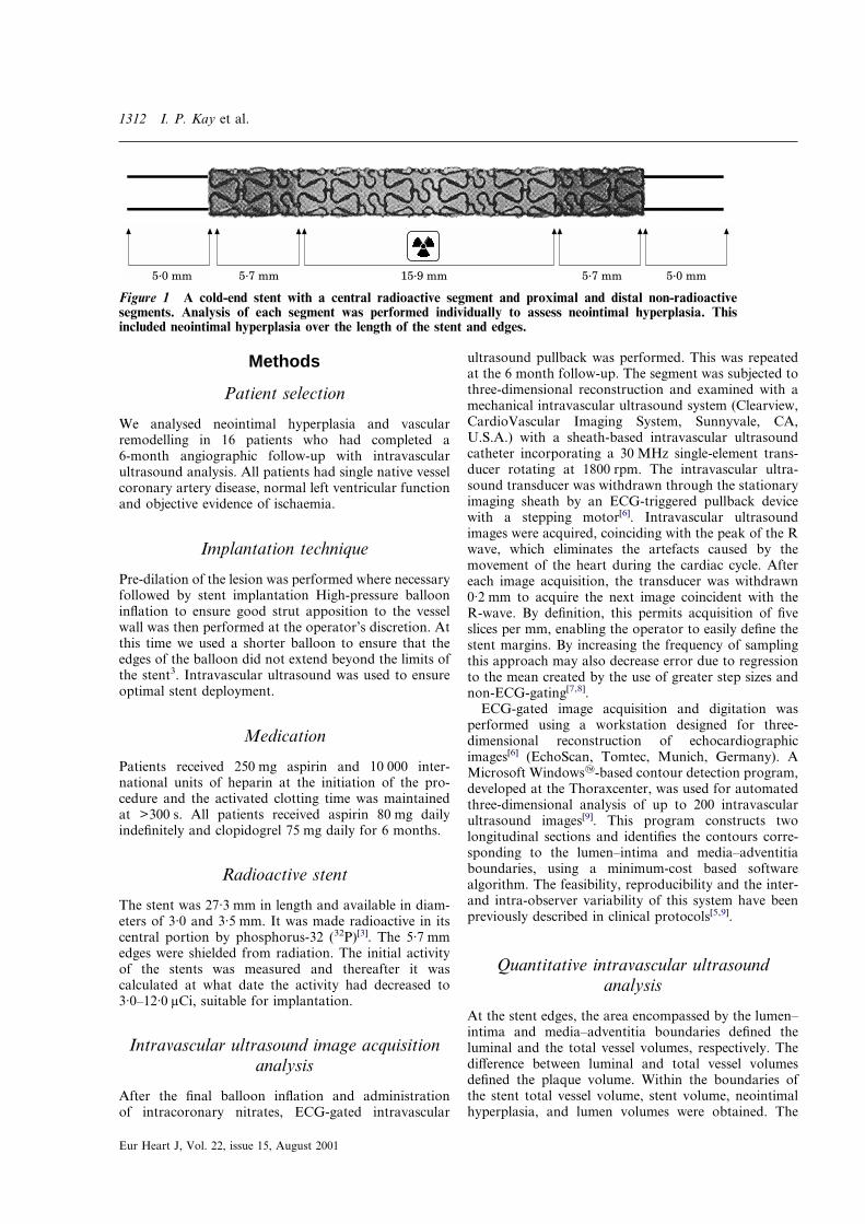
of neointimal hyperplasia at the 6-month follow-upin stents with activity levels >3 �Ci[3,4]. However, asignificant increase in neointimal hyperplasia was notedat the extremes of the stent and at the edges. Edgerestenosis was mainly due to an increase in plaque andto a lesser extent, remodelling of the native vesselwall[4,5]. A fall-off in radiation in areas receiving vascularinjury was proposed as a possible stimulatory mech-anism. In order to minimize the effect of vascularremodelling on stent-edge restenosis, the stent designwas modified. The ‘cold-end’ stent (Isostent� Inc., SanCarlos, CA, U.S.A.) was rendered radioactive in itsmid-portion (15·9 mm in length); the edges (5·7 mmeach) were non-radioactive (Fig. 1).
We aimed to analyse tissue growth within the stentand at its edges and to define the segments that had thegreatest propensity to restenosis after the implantationof a cold-end stent.
Revision submitted 7 November 2000, and accepted 22 November2000.
Correspondence: P. W. Serruys, MD, PhD, FACC, FESC,Professor of Interventional Cardiology, Thoraxcenter, AcademischZiekenhuis Rotterdam, PO Box 1738, Dr. Molewaterplein 40,3000 DR Rotterdam, The Netherlands.
� 2001 The European Society of Cardiology
1312 I. P. Kay et al.
Methods
Patient selection
We analysed neointimal hyperplasia and vascularremodelling in 16 patients who had completed a6-month angiographic follow-up with intravascularultrasound analysis. All patients had single native vesselcoronary artery disease, normal left ventricular functionand objective evidence of ischaemia.
Implantation technique
Pre-dilation of the lesion was performed where necessaryfollowed by stent implantation High-pressure ballooninflation to ensure good strut apposition to the vesselwall was then performed at the operator’s discretion. Atthis time we used a shorter balloon to ensure that theedges of the balloon did not extend beyond the limits ofthe stent3. Intravascular ultrasound was used to ensureoptimal stent deployment.
Medication
Patients received 250 mg aspirin and 10 000 inter-national units of heparin at the initiation of the pro-cedure and the activated clotting time was maintainedat >300 s. All patients received aspirin 80 mg dailyindefinitely and clopidogrel 75 mg daily for 6 months.
Radioactive stent
The stent was 27·3 mm in length and available in diam-eters of 3·0 and 3·5 mm. It was made radioactive in itscentral portion by phosphorus-32 (32P)[3]. The 5·7 mmedges were shielded from radiation. The initial activityof the stents was measured and thereafter it wascalculated at what date the activity had decreased to3·0–12·0 �Ci, suitable for implantation.
Intravascular ultrasound image acquisitionanalysis
After the final balloon inflation and administrationof intracoronary nitrates, ECG-gated intravascular
Eur Heart J, Vol. 22, issue 15, August 2001
ultrasound pullback was performed. This was repeatedat the 6 month follow-up. The segment was subjected tothree-dimensional reconstruction and examined with amechanical intravascular ultrasound system (Clearview,CardioVascular Imaging System, Sunnyvale, CA,U.S.A.) with a sheath-based intravascular ultrasoundcatheter incorporating a 30 MHz single-element trans-ducer rotating at 1800 rpm. The intravascular ultra-sound transducer was withdrawn through the stationaryimaging sheath by an ECG-triggered pullback devicewith a stepping motor[6]. Intravascular ultrasoundimages were acquired, coinciding with the peak of the Rwave, which eliminates the artefacts caused by themovement of the heart during the cardiac cycle. Aftereach image acquisition, the transducer was withdrawn0·2 mm to acquire the next image coincident with theR-wave. By definition, this permits acquisition of fiveslices per mm, enabling the operator to easily define thestent margins. By increasing the frequency of samplingthis approach may also decrease error due to regressionto the mean created by the use of greater step sizes andnon-ECG-gating[7,8].
ECG-gated image acquisition and digitation wasperformed using a workstation designed for three-dimensional reconstruction of echocardiographicimages[6] (EchoScan, Tomtec, Munich, Germany). AMicrosoft Windows�-based contour detection program,developed at the Thoraxcenter, was used for automatedthree-dimensional analysis of up to 200 intravascularultrasound images[9]. This program constructs twolongitudinal sections and identifies the contours corre-sponding to the lumen–intima and media–adventitiaboundaries, using a minimum-cost based softwarealgorithm. The feasibility, reproducibility and the inter-and intra-observer variability of this system have beenpreviously described in clinical protocols[5,9].
������������ ������� ������ ������
Figure 1 A cold-end stent with a central radioactive segment and proximal and distal non-radioactivesegments. Analysis of each segment was performed individually to assess neointimal hyperplasia. Thisincluded neointimal hyperplasia over the length of the stent and edges.
Quantitative intravascular ultrasoundanalysis
At the stent edges, the area encompassed by the lumen–intima and media–adventitia boundaries defined theluminal and the total vessel volumes, respectively. Thedifference between luminal and total vessel volumesdefined the plaque volume. Within the boundaries ofthe stent total vessel volume, stent volume, neointimalhyperplasia, and lumen volumes were obtained. The
Pattern of restenosis after radioactive stenting 1313
neointimal hyperplasia presented was a value measuredat follow-up (stent volume–lumen volume).
The assessment of total vessel volume in stentedpatients has previously been reported[5,10]. In our studythe delineation of the total vessel volume boundary waspossible in all stented patients. When the total vesselvolume boundary was not visible in a single cross-sectional view, the computer extrapolated it from thecontours of the immediately previous and followingcross-sections. In addition, the use of three-dimensionalreconstruction with multiple longitudinal views, facili-tates the visualization of vessel structures outside thestent.
Definitions and segments of analysis
Stent edges were defined as those volumes axially 5 mmproximal and distal to the final stent strut. In addition,segments in-stent proximally and distally were analysedseparately to assess neointimal hyperplasia in areaswhich were subject to injury and received stent implan-tation. Effectively, these were segments which received afall-off in radiation. Finally the in-stent radioactivesegment was analysed (see Fig. 1). To facilitate com-parison between the non-radioactive in-stent segments(5·7 mm) and the central radioactive segment (15·9 mm),lengths were normalized to a standard length (5 mm)and appropriate comparisons made. Restenosis wasdefined as an angiographic restenosis >50% at6-month follow-up, by off-line quantitative coronaryangiography.
Statistical analysis
Quantitative data are presented as mean�standarddeviation. Volumetric data derived from the three-dimensional reconstruction of the intravascular ultra-sound image were compared immediately aftertreatment and at follow-up using the two-tailed pairedStudent’s t-test. ANOVA was used to compare multiplevariables. A value of P<0·05 was considered statisticallysignificant.
The Medical Ethical Committee of the UniversityHospital Rotterdam approved the study and all patientsprovided written informed consent before the procedure.
Results
Baseline clinical and procedural characteristics aredescribed in Tables 1 and 2. Table 3 describesquantitative coronary angiography data pre- andpost-intervention and at the 6-month follow-up.
In-stent radioactive segment
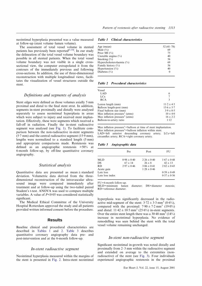
Neointimal hyperplasia measured within the margins ofthe stent is presented in Fig. 2. Intra-stent neointimal
hyperplasia was significantly decreased in the radio-active mid-segment of the stent: 3·72�3·3 mm3 (8·6%),compared with the proximal: 7·90�7·2 mm3 (19·0%)and distal: 11·42�10·5 mm3 (25·6%) in-stent segments.Over the entire stent length there was a 30·48 mm3 (14%)increase in neointimal hyperplasia. No evidence ofremodelling was seen behind the stent with the totalvessel volume remaining unchanged.
Table 1 Clinical characteristics
Age (mean) 52 (41–78)Male (%) 69Prior MI (%) 75Unstable angina (%) 40Smoking (%) 56Hypercholesterolaemia (%) 69Family history (%) 56Hypertension (%) 40Diabetes (%) 0
Table 2 Procedural characteristics
VesselLAD 6LCx 7RCA 3
Lesion length (mm) 11·2�4·5Balloon length-post (mm) 15·6�5·7Final balloon size (mm) 3·9�0·5Max inflation pressure1 (atms) 10�4·0Max inflation pressure2 (atms) 16�2·2Balloon-to-artery ratio 1·12
Max inflation pressure1=balloon at time of stent implantation.Max inflation pressure2=balloon inflation within stent.LAD=left anterior descending coronary artery; LCx=leftcircumflex artery; RCA=right coronary artery.
Table 3 Angiographic data
Pre Post FU
MLD 0·98�0·40 2·26�0·40 1·67�0·48DS 67�14 26�8 42�13RD 2·97�0·46 3·06�0·41 2·82�0·43Acute gain 1·28�0·46Late loss 0·59�0·49Late loss index 0·57�0·56
FU=6-month follow-up.MLD=minimum lumen diameter; DS=diameter stenosis;RD=reference diameter.
In-stent non-radioactive segment
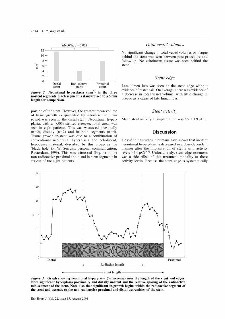
Significant neointimal in-growth was noted distally andproximally from 2–3 mm within the radioactive segmentand extended on average to the extremities (non-radioactive) of the stent (see Fig. 3). Four individualsexperienced angiographic restenosis in the proximal
Eur Heart J, Vol. 22, issue 15, August 2001
1314 I. P. Kay et al.
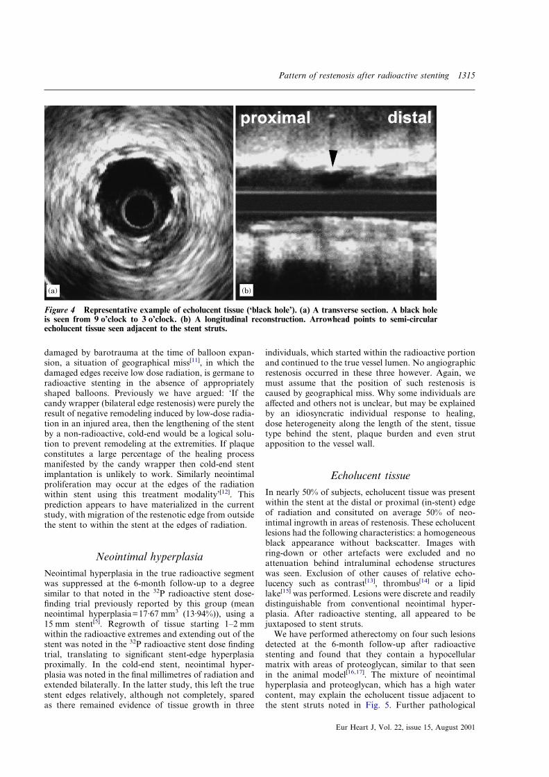
portion of the stent. However, the greatest mean volumeof tissue growth as quantified by intravascular ultra-sound was seen in the distal stent. Neointimal hyper-plasia, with a >50% stented cross-sectional area, wasseen in eight patients. This was witnessed proximally(n=2), distally (n=2) and in both segments (n=4).Tissue growth in-stent was due to a combination ofconventional neointimal hyperplasia and echolucent,hypodense material, described by this group as the‘black hole’ (P. W. Serruys, personal communication,Rotterdam, 1999). This was witnessed (Fig. 4) in thenon-radioactive proximal and distal in-stent segments insix out of the eight patients.
Eur Heart J, Vol. 22, issue 15, August 2001
Total vessel volumes
No significant change in total vessel volumes or plaquebehind the stent was seen between post-procedure andfollow-up. No echolucent tissue was seen behind thestent.
Stent edge
Late lumen loss was seen at the stent edge withoutevidence of restenosis. On average, there was evidence ofa decrease in total vessel volume, with little change inplaque as a cause of late lumen loss.
Stent activity
Mean stent activity at implantation was 6·9�1·9 �Ci.
0Proximal
stent
12
mm
3
Distalstent
Radioactivestent
10
8
6
4
2
ANOVA, p = 0·017
Figure 2 Neointimal hyperplasia (mm3) in the threein-stent segments. Each segment is standardized to a 5 mmlength for comparison.
��� ���
��
�
� ����
��� �� ���������
��
��
��
��
�
������������
Figure 3 Graph showing neointimal hyperplasia (% increase) over the length of the stent and edges.Note significant hyperplasia proximally and distally in-stent and the relative sparing of the radioactivemid-segment of the stent. Note also that significant in-growth begins within the radioactive segment ofthe stent and extends to the non-radioactive proximal and distal extremities of the stent.
Discussion
Dose-finding studies in humans have shown that in-stentneointimal hyperplasia is decreased in a dose-dependentmanner after the implantation of stents with activitylevels >3·0 �Ci[3,4]. Unfortunately, stent edge restenosiswas a side effect of this treatment modality at theseactivity levels. Because the stent edge is systematically
Pattern of restenosis after radioactive stenting 1315
damaged by barotrauma at the time of balloon expan-sion, a situation of geographical miss[11], in which thedamaged edges receive low dose radiation, is germane toradioactive stenting in the absence of appropriatelyshaped balloons. Previously we have argued: ‘If thecandy wrapper (bilateral edge restenosis) were purely theresult of negative remodeling induced by low-dose radia-tion in an injured area, then the lengthening of the stentby a non-radioactive, cold-end would be a logical solu-tion to prevent remodeling at the extremities. If plaqueconstitutes a large percentage of the healing processmanifested by the candy wrapper then cold-end stentimplantation is unlikely to work. Similarly neointimalproliferation may occur at the edges of the radiationwithin stent using this treatment modality’[12]. Thisprediction appears to have materialized in the currentstudy, with migration of the restenotic edge from outsidethe stent to within the stent at the edges of radiation.
Neointimal hyperplasiaNeointimal hyperplasia in the true radioactive segmentwas suppressed at the 6-month follow-up to a degreesimilar to that noted in the 32P radioactive stent dose-finding trial previously reported by this group (meanneointimal hyperplasia=17·67 mm3 (13·94%)), using a15 mm stent[5]. Regrowth of tissue starting 1–2 mmwithin the radioactive extremes and extending out of thestent was noted in the 32P radioactive stent dose findingtrial, translating to significant stent-edge hyperplasiaproximally. In the cold-end stent, neointimal hyper-plasia was noted in the final millimetres of radiation andextended bilaterally. In the latter study, this left the truestent edges relatively, although not completely, sparedas there remained evidence of tissue growth in three
individuals, which started within the radioactive portionand continued to the true vessel lumen. No angiographicrestenosis occurred in these three however. Again, wemust assume that the position of such restenosis iscaused by geographical miss. Why some individuals areaffected and others not is unclear, but may be explainedby an idiosyncratic individual response to healing,dose heterogeneity along the length of the stent, tissuetype behind the stent, plaque burden and even strutapposition to the vessel wall.
������
Figure 4 Representative example of echolucent tissue (‘black hole’). (a) A transverse section. A black holeis seen from 9 o’clock to 3 o’clock. (b) A longitudinal reconstruction. Arrowhead points to semi-circularecholucent tissue seen adjacent to the stent struts.
Echolucent tissueIn nearly 50% of subjects, echolucent tissue was presentwithin the stent at the distal or proximal (in-stent) edgeof radiation and consituted on average 50% of neo-intimal ingrowth in areas of restenosis. These echolucentlesions had the following characteristics: a homogeneousblack appearance without backscatter. Images withring-down or other artefacts were excluded and noattenuation behind intraluminal echodense structureswas seen. Exclusion of other causes of relative echo-lucency such as contrast[13], thrombus[14] or a lipidlake[15] was performed. Lesions were discrete and readilydistinguishable from conventional neointimal hyper-plasia. After radioactive stenting, all appeared to bejuxtaposed to stent struts.
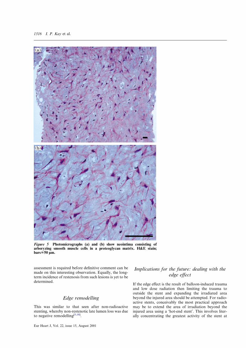
We have performed atherectomy on four such lesionsdetected at the 6-month follow-up after radioactivestenting and found that they contain a hypocellularmatrix with areas of proteoglycan, similar to that seenin the animal model[16,17]. The mixture of neointimalhyperplasia and proteoglycan, which has a high watercontent, may explain the echolucent tissue adjacent tothe stent struts noted in Fig. 5. Further pathological
Eur Heart J, Vol. 22, issue 15, August 2001
1316 I. P. Kay et al.
assessment is required before definitive comment can bemade on this interesting observation. Equally, the long-term incidence of restenosis from such lesions is yet to bedetermined.
Edge remodelling
This was similar to that seen after non-radioactivestenting, whereby non-restenotic late lumen loss was dueto negative remodelling[5,18].
Figure 5 Photomicrographs (a) and (b) show neointima consisting ofarboryzing smooth muscle cells in a proteoglycan matrix. H&E stain;bars=50 �m.
Eur Heart J, Vol. 22, issue 15, August 2001
Implications for the future: dealing with theedge effect
If the edge effect is the result of balloon-induced traumaand low dose radiation then limiting the trauma tooutside the stent and expanding the irradiated areabeyond the injured area should be attempted. For radio-active stents, conceivably the most practical approachmay be to extend the area of irradiation beyond theinjured area using a ‘hot-end stent’. This involves liter-ally concentrating the greatest activity of the stent at
Pattern of restenosis after radioactive stenting 1317
the stent edges; such stents are already undergoingmulticentre trials. A further therapeutic option is that ofhybrid treatment with radioactive stent implantationfollowed by catheter-based therapy localized to the stentedges only.
Conclusion
Cold-end stent implantation, a strategy devised to pre-vent edge restenosis after radioactive stenting results inmigration of the restenotic edge from outside the stent towithin the stent at the edges of radiation. This addscredence to the hypothesis that injury and low-doseradiation stimulate neointimal hyperplasia[19].
The Wenckebach award was made to P. W. Serruys by theDutch Heart Foundation and is utilized for brachytherapy researchin the catheterization laboratory. I. P. Kay is supported by theNational Heart Foundation of New Zealand, Auckland andthe Ian Gordon Mackenzie Scholarship, University of Otago,Dunedin, New Zealand.
References
[1] Farb A, Sangiorgi G, Carter AJ et al. Pathology of acute andchronic coronary stenting in humans. Circulation 1999; 99:44–52.
[2] Murphy JG, Schwartz RS, Edwards WD et al. Percutaneouspolymeric stents in porcine coronary arteries. Initial experi-ence with polyethylene terephthalate stents. Circulation 1992;86: 1596–1604.
[3] Wardeh AJ, Kay IP, Sabate M et al. �-particle-emittingradioactive stent implantation: a safety and feasibility study.Circulation 1999; 100: 1684–9.
[4] Albiero R, Adamian M, Kobayashi N et al. Short- andintermediate-term results of 32P radioactive �-emitting stentimplantation in patients with coronary artery disease: theMilan Dose-Response Study. Circulation 2000; 101: 18–26.
[5] Kay IP, Sabate M, Costa MA et al. Positive geometricvascular remodeling is seen after catheter-based radiationfollowed by conventional stent implantation, but not afterradioactive stent implantation. Circulation 2000; 102: 1434–9.
[6] von Birgelen C, Mintz GS, Nicosia A et al.Electrocardiogram-gated intravascular ultrasound image
acquisition after coronary stent deployment facilitates on-linethree-dimensional reconstruction and automated lumenquantification. J Am Coll Cardiol 1997; 30: 436–43.
[7] Bland JM, Altman DG. Some examples of regression towardsthe mean. BMJ 1994; 309 (6957): 780.
[8] von Birgelen C, de Feyter PJ, de Vrey EA et al. Simpson’s rulefor the volumetric ultrasound assessment of atheroscleroticcoronary arteries: a study with ECG-gated three-dimensionalintravascular ultrasound. Coron Artery Dis 1997; 6: 363–9.
[9] von Birgelen C, Di Mario C, Li W et al. Morphometricanalysis in three-dimensional intracoronary ultrasound: an invitro and in vivo study performed with a novel system for thecontour detection of lumen and plaque. Am Heart J 1996; 132:516–27.
[10] Prati F, Di Mario C, Moussa I. In-stent neointimalproliferation correlates with the amount of residual plaqueburden outside the stent. An intravascular ultrasound study.Circulation 1999; 99: 1011–14.
[11] Paterson R. The treatment of malignant disease by radio-therapy, 2nd edn. London: Edward Arnold Publishers Ltd,1963.
[12] Serruys PW, Kay IP. I like the candy, I hate the wrapper.Circulation 2000; 101: 3–7.
[13] Kay IP, Sabate M, Ligthart JMR, van der Giessen WJ, deFeyter PJ, Serruys PW. Intracoronary ultrasound longi-tudinal reconstruction of a postangioplasty coronary arterydissection. Circulation 1999; 99: e17.
[14] Serrano P, Kross JM, Ligthart JMR, Costa MA, Sabate M, deFeyter PJ. Diagnosis of an intracoronary thrombus withintravascular ultrasound. Circulation 2000; 101: e84–e85.
[15] Gronholdt M-L M, Nordestgaard BG, Wiebe BM, WilhjelmJE, Sillesen H. Echolucency of computerized ultrasoundimages of carotid atherosclerotic plaques are associated withincreased levels of triglyceride-rich lipoproteins as well asincreased plaque lipid content. Circulation 1998; 97: 34–40.
[16] Carter AJ, Scott D, Bailey L, Hoopes T, Jones R, Virmani R.Dose-response effects in an atherosclerotic porcine coronarymodel. Circulation 1999; 100: 1548–54.
[17] Hehrlein C, Kaiser S, Riessen R, Metz J, Fritz P, Kubler W.External beam radiation after stent implantation increasesneointimal hyperplasia by augmenting smooth muscle cellproliferation and extracellular matrix accumulation. J AmColl Cardiol 1999; 34: 561–6.
[18] Hoffmann R, Mintz GS, Dussaillant GR et al. Patterns andmechanism of in-stent restenosis. A serial intravascular ultra-sound study. Circulation 1996; 94: 1247–54.
[19] Weinberger J, Amols H, Ennis RD, Schwartz A, WiedermannJG, Marboe C. Intracoronary irradiation: Dose responsefor the prevention of restenosis in swine. Int J RadiationOncology Biol Phys 1996; 36: 767–75.
Eur Heart J, Vol. 22, issue 15, August 2001