Embed Size (px)
Citation preview
THE PERFORMANCE AND SCALABILITY OF DISTRIBUTED SHARED MEMORY CACHE COHERENCE PROTOCOLS
A DISSERTATION
SUBMITTED TO THE DEPARTMENT OF
ELECTRICAL ENGINEERING
AND THE COMMITTEE ON GRADUATE STUDIES
OF STANFORD UNIVERSITY
IN PARTIAL FULFILLMENT OF THE REQUIREMENTS
FOR THE DEGREE OF
DOCTOR OF PHILOSOPHY
Mark Andrew Heinrich
October 1998
ii
© Copyright 1998 by Mark Andrew Heinrich
All Rights Reserved

iii
I certify that I have read this dissertation and that in my opinion it isfully adequate, in scope and quality, as a dissertation for the degreeof Doctor of Philosophy.
_______________________________________John L. Hennessy, Principal Advisor
I certify that I have read this dissertation and that in my opinion it isfully adequate, in scope and quality, as a dissertation for the degreeof Doctor of Philosophy.
_______________________________________Oyekunle Olukotun
I certify that I have read this dissertation and that in my opinion it isfully adequate, in scope and quality, as a dissertation for the degreeof Doctor of Philosophy.
_______________________________________Dwight Nishimura
Approved for the University Committee on Graduate Studies:
_______________________________________
iv
Abstract
Distributed shared memory (DSM) machines are becoming an increasingly popular
way to increase parallelism beyond the limits of bus-based symmetric multiprocessors
(SMPs). The cache coherence protocol is an integral component of the memory system of
these DSM machines, yet the choice of cache coherence protocol is often made based on
implementation ease rather than performance. Most DSM machines run a fixed protocol,
encoded in hardware finite state machines, so trying to compare the performance of differ-
ent protocols involves comparing performance across different machines. Unfortunately,
this approach is doomed since differences in machine architecture or other design artifacts
can obfuscate the protocol comparison.
The Stanford FLASH (FLexible Architecture for SHared memory) multiprocessor pro-
vides an environment for running different cache coherence protocols on the same under-
lying hardware. In the FLASH system, the cache coherence protocols are written in
software that runs on a programmable controller specialized to efficiently run protocol
code sequences. Within this environment it is possible to hold everything else constant
and change only the cache coherence protocol code that the controller is running, thereby
making visible the impact that the protocol has on overall system performance.
This dissertation examines the performance of four full-fledged cache coherence proto-
cols for the Stanford FLASH multiprocessor at varying machine sizes from 1 to 128 pro-
cessors. The first protocol is a simple bit-vector protocol which degrades into a coarse-
vector protocol for machine sizes greater than 48 processors. The second protocol is the
dynamic pointer allocation protocol, which maintains the directory information in a linked
list rather than a bit-vector. The third protocol is the IEEE standard Scalable Coherent
Interface (SCI) protocol, with some enhancements to improve performance and some
extensions so that it can function properly within the FLASH environment. The fourth
protocol is a flat Cache Only Memory Architecture (COMA-F) protocol that provides
automatic hardware support for replication and migration of data at a cache line granular-
ity.
v
A framework is presented to discuss the data structures and salient features of these pro-
tocols in terms of their memory efficiency, direct protocol overhead, message efficiency,
and general protocol scalability. The protocols are then compared when running a mix of
scalable scientific applications from the SPLASH-2 application suite at different machine
sizes from 1 to 128 processors. In addition to these results, more stress is placed on the
memory system by running less-tuned versions of each application, as well as running
each application with small processor caches to show how the relative protocol perfor-
mance can change with different architectural parameters.
The results show that cache coherence protocol performance can be critical in DSM
systems, with over 2.5 times performance difference between the best and worst protocol
in some configurations. In addition, no single existing protocol always achieves the best
overall performance. Surprisingly, the best performing protocol changes with machine
size—even within the same application! Further, the best performing protocol changes
with application optimization level and with cache size. There are times when each proto-
col in this study is the best protocol, and there are times when each protocol is the worst.
In the end, the results argue for programmable protocols on scalable machines, or a new
and more flexible cache coherence protocol. For designers who want a single architecture
to span machine sizes and cache configurations with robust performance across a wide
spectrum of applications using existing cache coherence protocols, flexibility in the choice
of cache coherence protocol is vital.
vi
Acknowledgments
Many people have inspired, guided, helped, and laughed with (and sometimes at) me
during the seven years I spent at Stanford University, and I would like to thank them all for
a great graduate school experience. I first want to thank John Hennessy, my principal advi-
sor, who not only guided my research and the FLASH project as a whole, but also served
as a teaching mentor and role model as I embark on my new faculty career. His sugges-
tions and careful reviews of this dissertation have improved it greatly. I would also like to
thank Mark Horowitz for the often thankless job of managing the day-to-day details of the
FLASH project. In addition, I would like to thank Kunle Olukotun for being on my disser-
tation reading committee, and special thanks to Dwight Nishimura for agreeing to chair
my Ph.D. orals committee and also for serving on my reading committee.
The FLASH project was a very large effort, encompassing many faculty and students.
All of them have in some way contributed to this dissertation and I want to thank them
here. I was lucky enough to be involved with the FLASH project from the very beginning
and many of them are now among my best friends. I have already mentioned John Hen-
nessy and Mark Horowitz, but other faculty who were critical to the FLASH effort were
Mendel Rosenblum and Anoop Gupta. My fellow FLASH hardware design team members
were Jeff Kuskin, Dave Ofelt, Dave Nakahira, Jules Bergmann, Hema Kapadia, Jeff
Solomon, Ron Ho, and Evelina Yeung. Considering the size and complexity of the project,
producing a working chip in first silicon with that few members on the design team is an
amazing accomplishment—due in no small part to the quality and dedication of the hard-
ware designers.
Of course, the chip would not be of much use if the protocols and the software tools did
not exist. My protocol, simulator, and software tools comrades-in-arms were Joel Baxter,
John Heinlein, Ravi Soundararajan, Robert Bosch, Steve Herrod, and Jeff Gibson. With-
out their willingness to develop new tools, fix problems along the way, and generally put
up with me, this dissertation would not have been possible.

vii
I was also fortunate enough to know and work with many of the students in the DASH
project which preceded FLASH at Stanford, many of whom inspired me to begin working
in this field, and some of which continue to give me (mostly solicited) guidance today. I
would like to thank Dan Lenoski, Jim Laudon, Kourosh Gharachorloo, Wolf-Dietrich
Weber, Todd Mowry, Rich Simoni, and Jaswinder Pal Singh. From this group I would like
to especially thank Todd for his help with early versions of FlashLite, and Rich and J.P. for
their continued friendship and guidance.
Graduate student life is not all drudgery, and I would like to thank Chris Holt and
Andrew Erlichson for keeping things fun. I could not ask for better friends. And of course,
I must thank the members of the FLASH softball team. Focus, fire, coaches, and environ-
mental consciousness. C’mon now FLASH!
I owe a huge debt of gratitude to my parents for their love, support, and humor through-
out not only the course of my Ph.D. studies, but throughout my entire life. Thanks Mom
and Dad.
Finally, I would like to thank my wife and best friend, Kim. Her love and support is
unfailing and her patience and understanding during many long nights working was
unselfish and appreciated more than she knows. This work, and my life, is dedicated to
her.
Table of Contents viii
Table of Contents
Chapter 1 Introduction............................................................................................... 1
1.1 Distributed Shared Memory.................................................................................................21.2 Cache Coherence Protocol Design Space............................................................................41.3 Evaluating the Cache Coherence Protocols .........................................................................61.4 Research Contributions........................................................................................................71.5 Organization of the Dissertation ..........................................................................................8
Chapter 2 Cache Coherence Protocols.................................................................... 10
2.1 The Cache Coherence Problem..........................................................................................102.2 Directory-Based Coherence ...............................................................................................122.3 Bit-vector/Coarse-vector....................................................................................................162.4 Dynamic Pointer Allocation ..............................................................................................212.5 Scalable Coherent Interface ...............................................................................................252.6 Cache Only Memory Architecture.....................................................................................322.7 Which Protocol is Best?.....................................................................................................36
Chapter 3 FLASH Architecture............................................................................... 37
3.1 An Argument for Flexibility ..............................................................................................373.2 FLASH and MAGIC Architecture.....................................................................................383.3 MAGIC Subsystem Protocol Support................................................................................46
3.3.1 Processor Interface ..............................................................................................463.3.2 Network Interface................................................................................................503.3.3 I/O Interface.........................................................................................................513.3.4 Inbox....................................................................................................................523.3.5 Protocol Processor ...............................................................................................55
3.4 The Software Queue ..........................................................................................................573.5 Programming MAGIC .......................................................................................................59
Chapter 4 FLASH Protocol Implementations........................................................ 60
4.1 FLASH Protocol Development Environment....................................................................604.1.1 FLASH Protocol Development Tool Chain ........................................................63
4.2 FLASH Bit-vector/Coarse-vector Implementation............................................................654.2.1 Global Registers ..................................................................................................674.2.2 Message Types.....................................................................................................684.2.3 Jumptable Programming......................................................................................704.2.4 Additional Considerations ...................................................................................71
4.3 FLASH Dynamic Pointer Allocation Protocol Implementation........................................734.3.1 Global Registers ..................................................................................................764.3.2 Message Types.....................................................................................................774.3.3 Jumptable Programming......................................................................................784.3.4 Additional Considerations ...................................................................................78
4.4 FLASH SCI Implementation .............................................................................................804.4.1 FLASH SCI Cache States....................................................................................824.4.2 Differences Between FLASH SCI and IEEE Specification ................................834.4.3 Global Registers ..................................................................................................88
Table of Contents ix
4.4.4 Message Types.....................................................................................................884.4.5 Jumptable Programming......................................................................................904.4.6 Additional Considerations ...................................................................................91
4.5 FLASH COMA Implementation .......................................................................................934.5.1 Global Registers ..................................................................................................964.5.2 Message Types.....................................................................................................964.5.3 Jumptable Programming......................................................................................964.5.4 Additional Considerations ...................................................................................98
4.6 Protocol Summary .............................................................................................................99
Chapter 5 Simulation Methodology ...................................................................... 101
5.1 Applications .....................................................................................................................1015.2 The FLASH Simulator.....................................................................................................103
5.2.1 Processor Model ................................................................................................1045.2.2 FlashLite ............................................................................................................104
5.3 Synchronization ...............................................................................................................109
Chapter 6 Results .................................................................................................... 111
6.1 Key Questions Revisited..................................................................................................1116.2 DSM Latencies ................................................................................................................1126.3 Direct Protocol Overhead ................................................................................................1146.4 Message Overhead ...........................................................................................................1186.5 Application Performance .................................................................................................119
6.5.1 FFT.....................................................................................................................1206.5.2 Ocean.................................................................................................................1296.5.3 Radix-Sort .........................................................................................................1346.5.4 LU......................................................................................................................1376.5.5 Barnes-Hut.........................................................................................................1416.5.6 Water..................................................................................................................142
6.6 Application Summary ......................................................................................................143
Chapter 7 Conclusions, Related Work, and Beyond............................................ 146
7.1 Related Work ...................................................................................................................1477.2 Future Work .....................................................................................................................151
Appendix A Example Protocol Handlers ................................................................. 154
A.1 Bit-vector/Coarse-vector Handlers ..................................................................................154A.2 Dynamic Pointer Allocation Handlers .............................................................................159A.3 SCI Handlers....................................................................................................................162A.4 COMA Handlers ..............................................................................................................165
Appendix B Table of Results ..................................................................................... 170
References.......................................................................................................................175
List of Tables x
List of Tables
Table 3.1. Bandwidth of MAGIC Interfaces (MB/s) ..................................................40
Table 3.2. Processor Interface Commands .................................................................47
Table 3.3. Output Queue Space Scheduling Requirements ........................................54
Table 4.1. Jumptable Dispatch Capability ..................................................................62
Table 4.2. Bit-vector/Coarse-vector Global Registers ................................................67
Table 4.3. Bit-vector/Coarse-vector Message Type Encoding and Lane Assignment69
Table 4.4. Bit-vector/Coarse-vector Speculative Memory Operations.......................70
Table 4.5. Dynamic Pointer Allocation Global Registers...........................................77
Table 4.6. Additional Dynamic Pointer Allocation Message Types...........................77
Table 4.7. FLASH SCI Cache States ..........................................................................83
Table 4.8. SCI Global Registers .................................................................................88
Table 4.9. SCI Message Types and Lane Assignment for Cacheable Operations ......89
Table 4.10. SCI Speculative Memory Operations ........................................................90
Table 4.11. SCI Message Types and Lane Assignment for Roll Out Operations.........91
Table 4.12. COMA AM State Encodings .....................................................................95
Table 4.13. COMA Message Types and Lane Assignment for Cacheable Operations 97
Table 4.14. COMA Speculative Memory Operations ..................................................98
Table 4.15. FLASH Protocol Comparison..................................................................100
Table 5.1. Applications and Problem Sizes ..............................................................102
Table 5.2. Description of Less-Tuned Application Versions ....................................103
Table 5.3. MAGIC Latencies (10ns system cycles) .................................................108
Table 6.1. Read Latencies of Current DSM Machines .............................................113
Table 6.2. Hot-Spotting in FFT at 128 Processors, 64 KB Caches...........................129
Table 6.3. SCI’s Aversion to Hot-Spotting at 128 Processors ..................................139
Table B.1. Full Results ..............................................................................................171
List of Figures xi
List of Figures
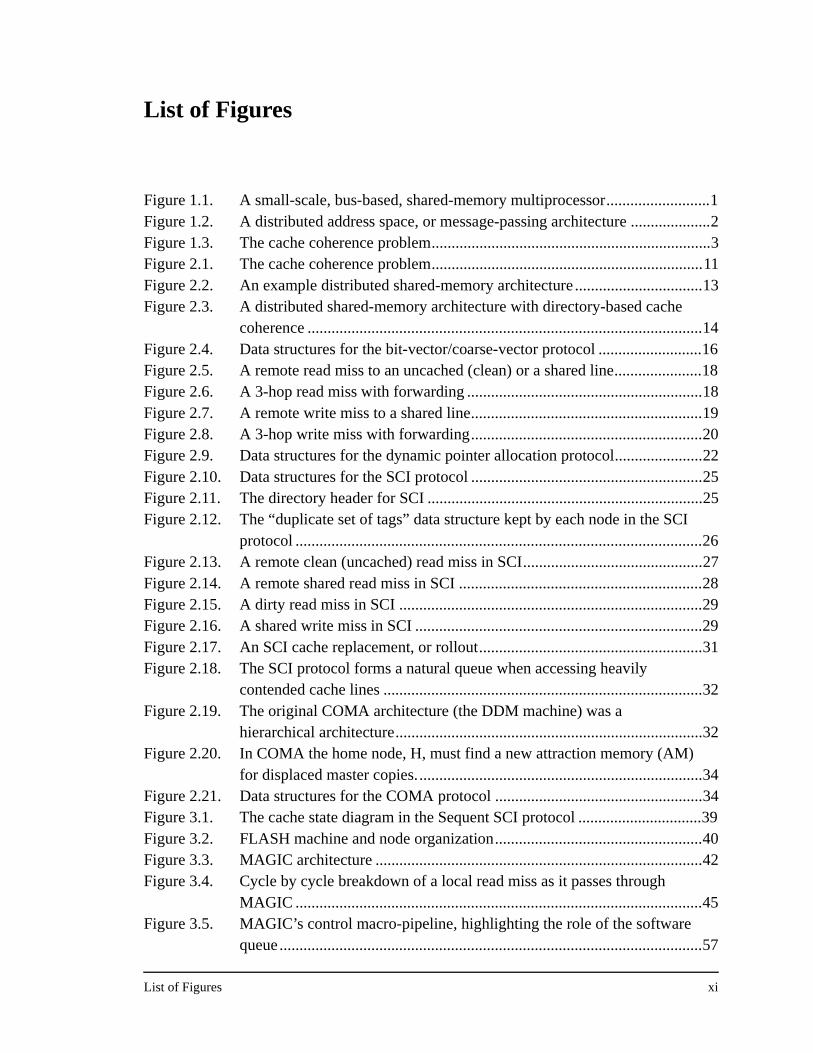
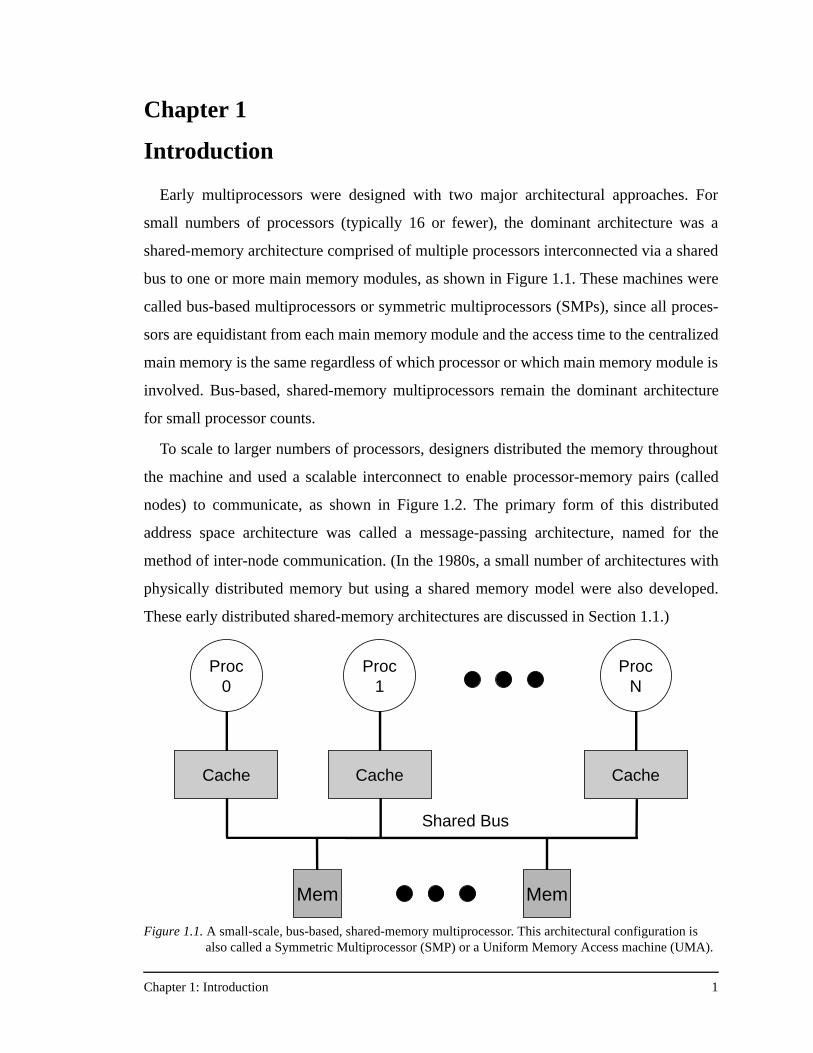
Figure 1.1. A small-scale, bus-based, shared-memory multiprocessor..........................1Figure 1.2. A distributed address space, or message-passing architecture ....................2Figure 1.3. The cache coherence problem......................................................................3Figure 2.1. The cache coherence problem....................................................................11Figure 2.2. An example distributed shared-memory architecture ................................13Figure 2.3. A distributed shared-memory architecture with directory-based cache
coherence ...................................................................................................14Figure 2.4. Data structures for the bit-vector/coarse-vector protocol ..........................16Figure 2.5. A remote read miss to an uncached (clean) or a shared line......................18Figure 2.6. A 3-hop read miss with forwarding ...........................................................18Figure 2.7. A remote write miss to a shared line..........................................................19Figure 2.8. A 3-hop write miss with forwarding..........................................................20Figure 2.9. Data structures for the dynamic pointer allocation protocol......................22Figure 2.10. Data structures for the SCI protocol ..........................................................25Figure 2.11. The directory header for SCI .....................................................................25Figure 2.12. The “duplicate set of tags” data structure kept by each node in the SCI
protocol ......................................................................................................26Figure 2.13. A remote clean (uncached) read miss in SCI.............................................27Figure 2.14. A remote shared read miss in SCI .............................................................28Figure 2.15. A dirty read miss in SCI ............................................................................29Figure 2.16. A shared write miss in SCI ........................................................................29Figure 2.17. An SCI cache replacement, or rollout........................................................31Figure 2.18. The SCI protocol forms a natural queue when accessing heavily
contended cache lines ................................................................................32Figure 2.19. The original COMA architecture (the DDM machine) was a
hierarchical architecture.............................................................................32Figure 2.20. In COMA the home node, H, must find a new attraction memory (AM)
for displaced master copies........................................................................34Figure 2.21. Data structures for the COMA protocol ....................................................34Figure 3.1. The cache state diagram in the Sequent SCI protocol ...............................39Figure 3.2. FLASH machine and node organization....................................................40Figure 3.3. MAGIC architecture ..................................................................................42Figure 3.4. Cycle by cycle breakdown of a local read miss as it passes through
MAGIC ......................................................................................................45Figure 3.5. MAGIC’s control macro-pipeline, highlighting the role of the software
queue..........................................................................................................57
List of Figures xii
Figure 4.1. FLASH protocol development chain .........................................................63Figure 4.2. The jump optimizer Perl script ..................................................................64Figure 4.3. C data structure for the directory entry in the bit-vector/coarse-vector
protocol ......................................................................................................65Figure 4.4. C data structure for the directory header in the dynamic pointer
allocation protocol .....................................................................................74Figure 4.5. C data structure for the pointer/link store in the dynamic pointer
allocation protocol .....................................................................................76Figure 4.6. C data structure for the directory entry in the FLASH SCI protocol.........80Figure 4.7. C data structure for an entry in the duplicate set of tags in the SCI
protocol ......................................................................................................81Figure 4.8. C data structure for the directory header in the FLASH COMA protocol 94Figure 5.1. FlashLite threads package code example.................................................105Figure 5.2. FlashLite threads modeling the entire FLASH system............................107Figure 6.1. FLASH protocol latency and occupancy comparison .............................115Figure 6.2. Average message overhead (normalized to the bit-vector/coarse-vector
protocol) across all the applications in this study ....................................118Figure 6.3. Results for prefetched FFT.......................................................................120Figure 6.4. Relative protocol message overhead for prefetched FFT.........................122Figure 6.5. Results for prefetched FFT with no data placement. ...............................124Figure 6.6. Results for prefetched FFT with no data placement and an unstaggered
transpose phase ........................................................................................126Figure 6.7. Results for prefetched FFT with no data placement, an unstaggered
transpose phase, and 64 KB processor caches .........................................128Figure 6.8. Results for prefetched Ocean ...................................................................130Figure 6.9. Results for prefetched Ocean with no data placement.............................132Figure 6.10. Results for prefetched Ocean with no data placement and 64 KB
processor caches ......................................................................................133Figure 6.11. Results for prefetched Radix-Sort............................................................135Figure 6.12. Results for prefetched Radix-Sort with no data placement .....................137Figure 6.13. Results for prefetched LU........................................................................138Figure 6.14. Results for prefetched LU with no data placement, and full barriers
between the three communication phases................................................139Figure 6.15. Results for prefetched LU with no data placement, full barriers between
the three communication phases, and 64 KB processor caches...............140Figure 6.16. Results for Barnes-Hut.............................................................................141Figure 6.17. Results for Water......................................................................................143Figure A.1. The PILocalGet handler for the bit-vector/coarse-vector protocol..........155Figure A.2. The scheduled assembly language for the portions of the PILocalGet
handler in Figure A.1 ...............................................................................157Figure A.3. The PILocalGet handler for the dynamic pointer allocation protocol. ....160
List of Figures xiii
Figure A.4. The NILocalGet handler for the dynamic pointer allocation protocol ....161Figure A.5. The PIRemoteGet handler for the SCI protocol ......................................163Figure A.6. The NILocalGet handler for the SCI protocol .........................................164Figure A.7. The PIRemoteGet handler for the COMA protocol.................................166Figure A.8. The NIRemotePut handler for the COMA protocol ................................168
Chapter 1: Introduction 1
Chapter 1
Introduction
Early multiprocessors were designed with two major architectural approaches. For
small numbers of processors (typically 16 or fewer), the dominant architecture was a
shared-memory architecture comprised of multiple processors interconnected via a shared
bus to one or more main memory modules, as shown in Figure 1.1. These machines were
called bus-based multiprocessors or symmetric multiprocessors (SMPs), since all proces-
sors are equidistant from each main memory module and the access time to the centralized
main memory is the same regardless of which processor or which main memory module is
involved. Bus-based, shared-memory multiprocessors remain the dominant architecture
for small processor counts.
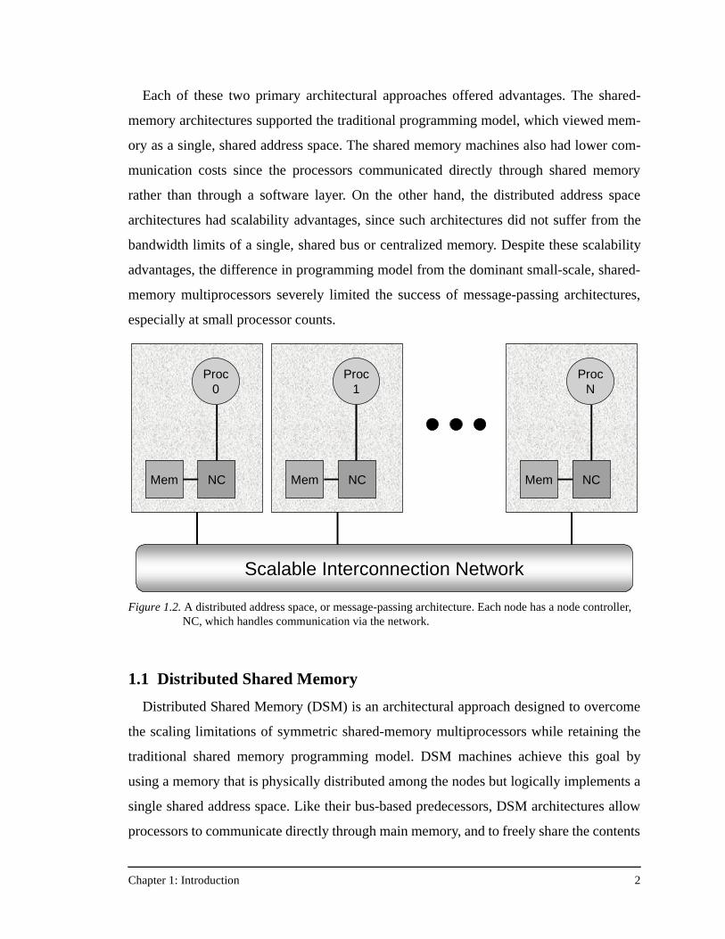
To scale to larger numbers of processors, designers distributed the memory throughout
the machine and used a scalable interconnect to enable processor-memory pairs (called
nodes) to communicate, as shown in Figure 1.2. The primary form of this distributed
address space architecture was called a message-passing architecture, named for the
method of inter-node communication. (In the 1980s, a small number of architectures with
physically distributed memory but using a shared memory model were also developed.
These early distributed shared-memory architectures are discussed in Section 1.1.)
Figure 1.1. A small-scale, bus-based, shared-memory multiprocessor. This architectural configuration is also called a Symmetric Multiprocessor (SMP) or a Uniform Memory Access machine (UMA).
Proc0
Cache
ProcN
Cache
Shared Bus
Mem Mem
Proc1
Cache
Chapter 1: Introduction 2
Each of these two primary architectural approaches offered advantages. The shared-
memory architectures supported the traditional programming model, which viewed mem-
ory as a single, shared address space. The shared memory machines also had lower com-
munication costs since the processors communicated directly through shared memory
rather than through a software layer. On the other hand, the distributed address space
architectures had scalability advantages, since such architectures did not suffer from the
bandwidth limits of a single, shared bus or centralized memory. Despite these scalability
advantages, the difference in programming model from the dominant small-scale, shared-
memory multiprocessors severely limited the success of message-passing architectures,
especially at small processor counts.
1.1 Distributed Shared Memory
Distributed Shared Memory (DSM) is an architectural approach designed to overcome
the scaling limitations of symmetric shared-memory multiprocessors while retaining the
traditional shared memory programming model. DSM machines achieve this goal by
using a memory that is physically distributed among the nodes but logically implements a
single shared address space. Like their bus-based predecessors, DSM architectures allow
processors to communicate directly through main memory, and to freely share the contents
Figure 1.2. A distributed address space, or message-passing architecture. Each node has a node controller, NC, which handles communication via the network.
Proc0
NCMem
Proc1
NCMem
ProcN
NCMem
Scalable Interconnection Network
Chapter 1: Introduction 3
of any memory module in the system. DSM multiprocessors have the same basic organi-
zation as the machines in Figure 1.2.
The first DSM architectures appeared in the late 1970s and continued through the early
1980s, embodied in three machines: the Carnegie Mellon Cm* [54], the IBM RP3 [38],
and the BBN Butterfly [5]. All these machines implemented a shared address space where
the time to access a datum depended on the memory module in which that datum resided.
Because of the resulting variability in memory access times, the name Non-Uniform
Memory Access (NUMA) machines was also given to these architectures. Although the
exact access time for a datum in a NUMA architecture depended on which memory mod-
ule contained the datum, by far the largest difference in access time was between
addresses in local memory and addresses in remote memory. Because these access times
could differ by a factor of 10 or more and there were no simple mechanisms to hide these
differences, it proved difficult to program these early distributed shared-memory
machines.
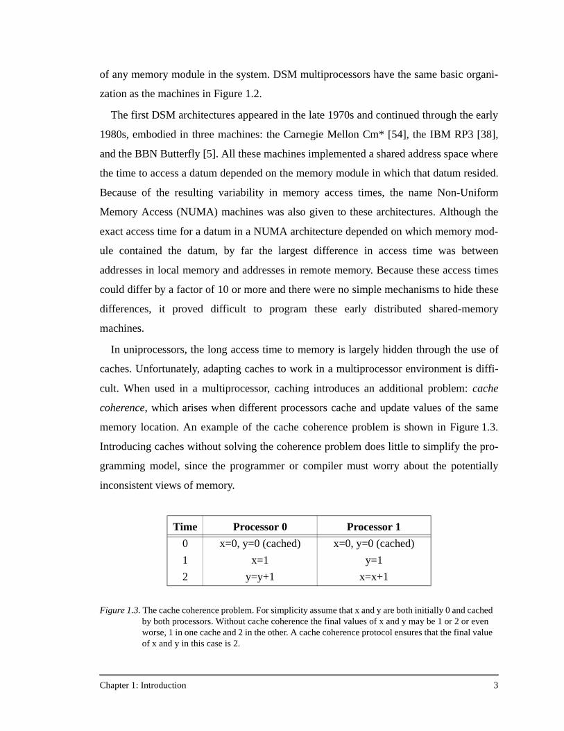
In uniprocessors, the long access time to memory is largely hidden through the use of
caches. Unfortunately, adapting caches to work in a multiprocessor environment is diffi-
cult. When used in a multiprocessor, caching introduces an additional problem: cache
coherence, which arises when different processors cache and update values of the same
memory location. An example of the cache coherence problem is shown in Figure 1.3.
Introducing caches without solving the coherence problem does little to simplify the pro-
gramming model, since the programmer or compiler must worry about the potentially
inconsistent views of memory.
Figure 1.3. The cache coherence problem. For simplicity assume that x and y are both initially 0 and cached by both processors. Without cache coherence the final values of x and y may be 1 or 2 or even worse, 1 in one cache and 2 in the other. A cache coherence protocol ensures that the final value of x and y in this case is 2.
Time Processor 0 Processor 1
0 x=0, y=0 (cached) x=0, y=0 (cached)
1 x=1 y=1
2 y=y+1 x=x+1
Chapter 1: Introduction 4
Solving the coherence problem in hardware requires a cache coherence protocol that
enforces the rules of the particular memory consistency model in use, and ensures that a
processor will always see a legal value of a datum. There are two classes of cache coher-
ence protocols: snoopy-based protocols [36] for small-scale, bus-based machines, and
directory-based protocols [9][55] for more scalable machines. Chapter 2 details the cache
coherence problem on both small-scale and large-scale shared-memory machines, and
describes both snoopy-based protocols and the more scalable, and more complex, direc-
tory-based protocols.
In the late 1980s and early 1990s, the development of directory-based cache coherence
protocols allowed the creation of cache-coherent distributed shared-memory multiproces-
sors, and the addition of processor caches to the original DSM architecture shown in
Figure 1.2. The availability of cache coherence, and hence software compatibility with
small-scale bus-based machines, popularized the commercial use of DSM machines for
scalable multiprocessors. These DSM multiprocessors are also called Cache Coherent
Non-Uniform Memory Access (CC-NUMA) machines, the latter characteristic arising
from the use of distributed memory. All existing scalable cache coherence protocols rely
on the use of distributed directories [2], but beyond that the protocols vary widely in how
they deal with scalability, as well as what techniques they use to reduce remote memory
latency.
1.2 Cache Coherence Protocol Design Space
Commercial CC-NUMA multiprocessors use variations on three major protocols: bit-
vector/coarse-vector [20][30][60], SCI [7][14][32], and COMA [8]. In addition, a number
of other protocols have been proposed for use in research machines [3][10][39][45][61].
The research protocols are for the most part similar, with an emphasis on changing the bit-
vector directory organization to scale more gracefully to larger numbers of processors.
From this list of research protocols, this dissertation adds the dynamic pointer allocation
protocol to the set of commercial protocols, and quantitatively compares each of the proto-
cols.
A cache coherence protocol can be evaluated on how well it deals with the following
four issues:
Chapter 1: Introduction 5
Protocol memory efficiency: how much memory overhead does the protocol require?
Memory usage is critical for scalability. This dissertation considers only protocols that
have memory overhead that scales with the number of processors. To achieve efficient
scaling of memory overhead, some protocols use hybrid solutions (such as a coarse-vector
extension of a standard bit-vector protocol), while others keep sharing information in non-
bit-vector data structures to reduce memory overhead (e.g., an SCI scheme). The result is
that significant differences in memory overhead can still exist in scalable coherence proto-
cols.
Direct protocol overhead: how much overhead do basic protocol operations require?
This often relates to how directory information is stored and updated, as well as attempts
to reduce global message traffic. Direct protocol overhead is the execution time for indi-
vidual protocol operations, measured by the number of clock cycles needed per operation.
This research splits the direct protocol overhead into two parts: the latency overhead and
the occupancy overhead. In DSM architectures, the node controller contributes to the
latency of each message it handles. More subtly, even after the controller sends the reply
message it may continue with bookkeeping or state manipulations. This type of overhead
does not affect the latency of the current message, but it may affect the latency of subse-
quent messages because it determines the rate at which the node controller can handle
messages. This direct protocol overhead is controller occupancy, or the inverse of control-
ler bandwidth. Keeping both latency and occupancy to a minimum are critical in high per-
formance DSM machines [25].
Message efficiency: how well does the protocol perform as measured by the global traf-
fic generated? Most protocol optimizations try to reduce message traffic, so this aspect is
accounted for in message efficiency. The existing protocols vary widely in this dimension.
For example, COMA tries to reduce global traffic by migrating cache lines, potentially
reducing global message traffic and improving performance significantly. Other protocols
sacrifice message efficiency (e.g., coarse-vector) to achieve memory scalability while
maintaining protocol simplicity. Still others add traffic in the form of replacement hints
(e.g., dynamic pointer allocation) to maintain precise sharing information.
Chapter 1: Introduction 6
Protocol scalability: Protocol scalability depends on both minimizing message traffic
and on avoiding contention. In the latter area, some protocols (such as SCI) have explicit
features to reduce contention and hot-spotting in the memory system.
The goal of this dissertation is to perform a fair, quantitative comparison of these four
cache coherence protocols, and to achieve a better understanding of the conditions under
which each protocol thrives and under which each protocol suffers. Through this compari-
son, this research demonstrates the utility of a programmable node controller that allows
flexibility in the choice of cache coherence protocol. The results of this study can also be
used to guide the construction of protocols for future, more robust, scalable multiproces-
sors.
1.3 Evaluating the Cache Coherence Protocols
The tradeoffs among these coherence protocols are extremely complex. No existing
protocol is able to optimize its behavior in all four of the areas outlined above. Instead, a
protocol focuses on some aspects, usually at the expense of others. While these tradeoffs
and their qualitative effects are important, the bottom line remains how well a given proto-
col performs in practice. Determining this requires careful accounting of the actual over-
head encountered in implementing each protocol. Although message traffic will also be
crucial to performance, several protocols trade protocol complexity (and therefore an
increase in direct protocol overhead) for a potential reduction in memory traffic. Under-
standing this tradeoff is critical.
Perhaps the most difficult aspect of such an evaluation is performing a fair comparison
of the protocol implementations. Because most DSM machines fix the coherence protocol
in hardware, comparing different DSM protocols means comparing performance across
different machines. This is problematic because differences in machine architecture,
design technology, or other artifacts can obfuscate the protocol comparison. Fortunately,
the FLASH machine [28] being built at Stanford University provides a platform for under-
taking such a study. FLASH uses a programmable protocol engine that allows the imple-
mentation of different protocols while using an identical main processor, cache, memory,
and interconnect. This focuses the evaluation on the differences introduced by the proto-
Chapter 1: Introduction 7
cols themselves. Nonetheless, such a study does involve the non-trivial task of implement-
ing and tuning each cache coherence protocol.
This research provides an implementation-based, quantitative analysis of the perfor-
mance, scalability, and robustness of four scalable cache coherence protocols running on
top of a single architecture, the Stanford FLASH multiprocessor. The four coherence pro-
tocols examined are bit-vector/coarse-vector, dynamic pointer allocation, SCI, and
COMA. Each protocol is a complete and working implementation that runs on a real
machine (FLASH). This is critical in a comparative performance evaluation since each
protocol is known to be correct and to handle all deadlock avoidance cases, some of which
can be quite subtle and easily overlooked in a paper-design or high-level protocol imple-
mentation.
1.4 Research Contributions
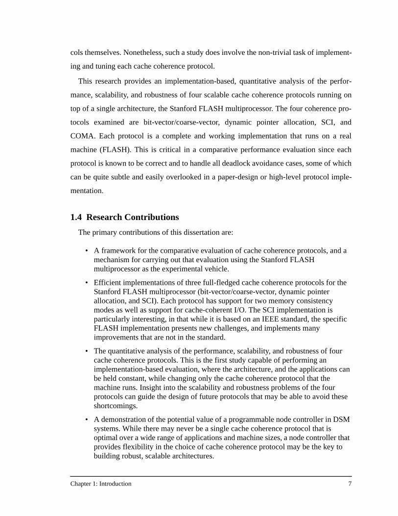
The primary contributions of this dissertation are:
• A framework for the comparative evaluation of cache coherence protocols, and a mechanism for carrying out that evaluation using the Stanford FLASH multiprocessor as the experimental vehicle.
• Efficient implementations of three full-fledged cache coherence protocols for the Stanford FLASH multiprocessor (bit-vector/coarse-vector, dynamic pointer allocation, and SCI). Each protocol has support for two memory consistency modes as well as support for cache-coherent I/O. The SCI implementation is particularly interesting, in that while it is based on an IEEE standard, the specific FLASH implementation presents new challenges, and implements many improvements that are not in the standard.
• The quantitative analysis of the performance, scalability, and robustness of four cache coherence protocols. This is the first study capable of performing an implementation-based evaluation, where the architecture, and the applications can be held constant, while changing only the cache coherence protocol that the machine runs. Insight into the scalability and robustness problems of the four protocols can guide the design of future protocols that may be able to avoid these shortcomings.
• A demonstration of the potential value of a programmable node controller in DSM systems. While there may never be a single cache coherence protocol that is optimal over a wide range of applications and machine sizes, a node controller that provides flexibility in the choice of cache coherence protocol may be the key to building robust, scalable architectures.
Chapter 1: Introduction 8
1.5 Organization of the Dissertation
This chapter began by describing the architectural history of multiprocessors and out-
lining the series of events that led to commercial DSM machines, most notably the devel-
opment of directory-based cache coherence protocols. The design space of distributed
shared-memory cache coherence protocols was presented next, along with a framework
for analyzing coherence protocols. Section 1.3 described the problem of evaluating coher-
ence protocols, and proposed a possible solution: the implementation of each protocol on
the flexible Stanford FLASH multiprocessor, and their subsequent comparative evalua-
tion. This quantitative evaluation is the focus of this dissertation.
Chapter 2 discusses the role of cache coherence protocols in shared-memory machines,
and explains why the transition from bus-based snoopy coherence protocols to distributed
directory-based protocols is necessary as the machine size scales. Each of the four DSM
cache coherence protocols in this study are then introduced, with discussion of the direc-
tory organization, memory overhead, and high-level goals of each protocol.
Chapter 3 discusses the details of the Stanford FLASH multiprocessor architecture, par-
ticularly those architectural details that are exposed to the protocol designer. Implement-
ing fully functional versions of four cache coherence protocols on a real machine is a
challenge, and Chapter 3 discusses some of the issues in designing correct coherence pro-
tocols for FLASH.
With an understanding of the FLASH machine, Chapter 4 returns to each of the four
cache coherence protocols and presents the particular FLASH implementation in detail.
For each protocol, Chapter 4 details the protocol data structures, the layout and description
of each field in the data structures, the network message types, the protocol dispatch con-
ditions, and additional implementation considerations and resource usage issues. Example
protocol handlers are presented for each protocol in Appendix A, highlighting some key
aspects of that protocol. The chapter concludes with a table comparing each implementa-
tion in terms of handler counts, code size, and high-level protocol characteristics.
Chapter 5 describes the simulation methodology used in the experiments in this study.
The results in this research come from a detailed simulation environment, and both the
processor model and the memory system simulator are discussed in detail. Because both
Chapter 1: Introduction 9
the applications and the processor count affect the protocol comparison, this research
employs a variety of different applications on machines ranging from 1 to 128 processors.
Chapter 5 describes each application, and explains how each application is simulated in
both tuned and un-tuned form. The application variety in this evaluation highlights differ-
ent protocol characteristics, and evokes the relative benefits of some protocols.
Chapter 6 presents the results of comparing the performance, scalability, and robustness
of these four protocols on machine sizes from 1 to 128 processors, using the applications
described in Chapter 5. Chapter 6 begins by characterizing some of the basic performance
metrics for these protocols (latency and occupancy for both local and remote accesses).
Then detailed breakdowns of execution time are shown for each protocol and each appli-
cation, complete with an analysis of the major issues for each application, including
whether the most important characteristics are direct protocol overhead, message effi-
ciency, or issues of inherent protocol scalability.
Chapter 7 summarizes the findings of this research and discusses both related work and
future research possibilities.
Chapter 2: Cache Coherence Protocols 10
Chapter 2
Cache Coherence Protocols
The presence of caches in current-generation distributed shared-memory multiproces-
sors improves performance by reducing the processor’s memory access time and by
decreasing the bandwidth requirements of both the local memory module and the global
interconnect. Unfortunately, the local caching of data introduces the cache coherence
problem. Early distributed shared-memory machines left it to the programmer to deal with
the cache coherence problem, and consequently these machines were considered difficult
to program [5][38][54]. Today’s multiprocessors solve the cache coherence problem in
hardware by implementing a cache coherence protocol. This chapter outlines the cache
coherence problem and describes how cache coherence protocols solve it.
In addition, this chapter discusses several different varieties of cache coherence proto-
cols including their advantages and disadvantages, their organization, their common pro-
tocol transitions, and some examples of machines that implement each protocol.
Ultimately a designer has to choose a protocol to implement, and this should be done care-
fully. Protocol choice can lead to differences in cache miss latencies and differences in the
number of messages sent through the interconnection network, both of which can lead to
differences in overall application performance. Moreover, some protocols have high-level
properties like automatic data distribution or distributed queueing that can help applica-
tion performance. Before discussing specific protocols, however, let us examine the cache
coherence problem in distributed shared-memory machines in detail.
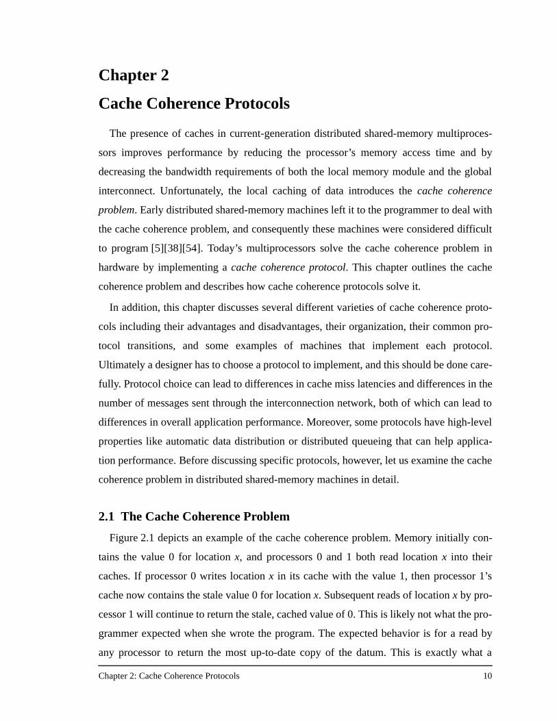
2.1 The Cache Coherence Problem
Figure 2.1 depicts an example of the cache coherence problem. Memory initially con-
tains the value 0 for location x, and processors 0 and 1 both read location x into their
caches. If processor 0 writes location x in its cache with the value 1, then processor 1’s
cache now contains the stale value 0 for location x. Subsequent reads of location x by pro-
cessor 1 will continue to return the stale, cached value of 0. This is likely not what the pro-
grammer expected when she wrote the program. The expected behavior is for a read by
any processor to return the most up-to-date copy of the datum. This is exactly what a
Chapter 2: Cache Coherence Protocols 11
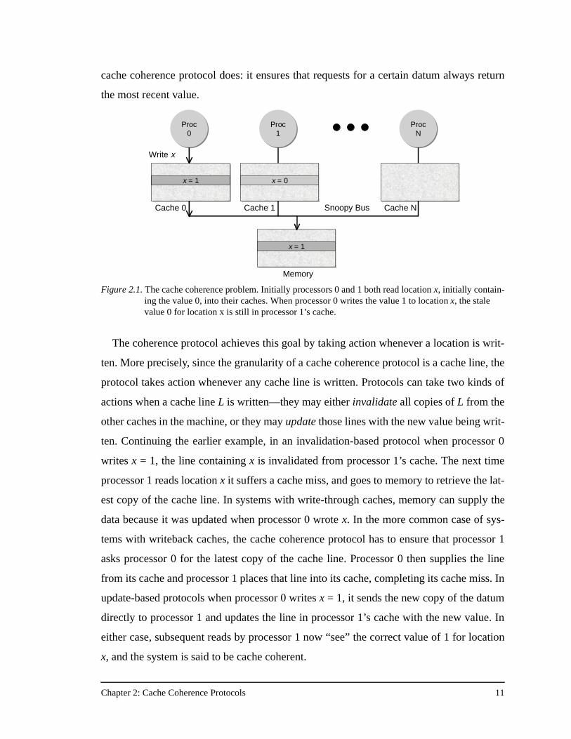
cache coherence protocol does: it ensures that requests for a certain datum always return
the most recent value.
The coherence protocol achieves this goal by taking action whenever a location is writ-
ten. More precisely, since the granularity of a cache coherence protocol is a cache line, the
protocol takes action whenever any cache line is written. Protocols can take two kinds of
actions when a cache line L is written—they may either invalidate all copies of L from the
other caches in the machine, or they may update those lines with the new value being writ-
ten. Continuing the earlier example, in an invalidation-based protocol when processor 0
writes x = 1, the line containing x is invalidated from processor 1’s cache. The next time
processor 1 reads location x it suffers a cache miss, and goes to memory to retrieve the lat-
est copy of the cache line. In systems with write-through caches, memory can supply the
data because it was updated when processor 0 wrote x. In the more common case of sys-
tems with writeback caches, the cache coherence protocol has to ensure that processor 1
asks processor 0 for the latest copy of the cache line. Processor 0 then supplies the line
from its cache and processor 1 places that line into its cache, completing its cache miss. In
update-based protocols when processor 0 writes x = 1, it sends the new copy of the datum
directly to processor 1 and updates the line in processor 1’s cache with the new value. In
either case, subsequent reads by processor 1 now “see” the correct value of 1 for location
x, and the system is said to be cache coherent.
Figure 2.1. The cache coherence problem. Initially processors 0 and 1 both read location x, initially contain-ing the value 0, into their caches. When processor 0 writes the value 1 to location x, the stale value 0 for location x is still in processor 1’s cache.
Proc0
Proc0
x = 1
Memory
x = 1
Write x
Cache 0
ProcN
ProcN
Cache NSnoopy Bus
Proc1
Proc1
x = 0
Cache 1
Chapter 2: Cache Coherence Protocols 12
Most modern cache-coherent multiprocessors use the invalidation technique rather than
the update technique since it is easier to implement in hardware. As cache line sizes con-
tinue to increase the invalidation-based protocols remain popular because of the increased
number of updates required when writing a cache line sequentially with an update-based
coherence protocol. There are times however, when using an update-based protocol is
superior. These include accessing heavily contended lines and some types of synchroniza-
tion variables. Typically designers choose an invalidation-based protocol and add some
special features to handle heavily contended synchronization variables. All the protocols
presented in this paper are invalidation-based cache coherence protocols, and a later sec-
tion is devoted to the discussion of synchronization primitives.
2.2 Directory-Based Coherence
The previous section describes the cache coherence problem and introduces the cache
coherence protocol as the agent that solves the coherence problem. But the question
remains, how do cache coherence protocols work?
There are two main classes of cache coherence protocols, snoopy protocols and direc-
tory-based protocols. Snoopy protocols require the use of a broadcast medium in the
machine and hence apply only to small-scale bus-based multiprocessors. In these broad-
cast systems each cache “snoops” on the bus and watches for transactions which affect it.
Any time a cache sees a write on the bus it invalidates that line out of its cache if it is
present. Any time a cache sees a read request on the bus it checks its cache to see if it has
the most recent copy of the data, and if so, responds to the bus request. These snoopy bus-
based systems are easy to build, but unfortunately as the number of processors on the bus
increase, the single shared bus becomes a bandwidth bottleneck and the snoopy protocol’s
reliance on a broadcast mechanism becomes a severe scalability limitation.
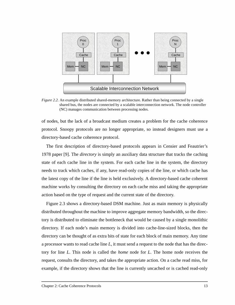
To address these problems, architects have adopted the distributed shared memory
(DSM) architecture. In a DSM multiprocessor each node contains the processor and its
caches, a portion of the machine’s physically distributed main memory, and a node con-
troller which manages communication within and between nodes (see Figure 2.2). Rather
than being connected by a single shared bus, the nodes are connected by a scalable inter-
connection network. The DSM architecture allows multiprocessors to scale to thousands
Chapter 2: Cache Coherence Protocols 13
of nodes, but the lack of a broadcast medium creates a problem for the cache coherence
protocol. Snoopy protocols are no longer appropriate, so instead designers must use a
directory-based cache coherence protocol.
The first description of directory-based protocols appears in Censier and Feautrier’s
1978 paper [9]. The directory is simply an auxiliary data structure that tracks the caching
state of each cache line in the system. For each cache line in the system, the directory
needs to track which caches, if any, have read-only copies of the line, or which cache has
the latest copy of the line if the line is held exclusively. A directory-based cache coherent
machine works by consulting the directory on each cache miss and taking the appropriate
action based on the type of request and the current state of the directory.
Figure 2.3 shows a directory-based DSM machine. Just as main memory is physically
distributed throughout the machine to improve aggregate memory bandwidth, so the direc-
tory is distributed to eliminate the bottleneck that would be caused by a single monolithic
directory. If each node’s main memory is divided into cache-line-sized blocks, then the
directory can be thought of as extra bits of state for each block of main memory. Any time
a processor wants to read cache line L, it must send a request to the node that has the direc-
tory for line L. This node is called the home node for L. The home node receives the
request, consults the directory, and takes the appropriate action. On a cache read miss, for
example, if the directory shows that the line is currently uncached or is cached read-only
Figure 2.2. An example distributed shared-memory architecture. Rather than being connected by a single shared bus, the nodes are connected by a scalable interconnection network. The node controller (NC) manages communication between processing nodes.
Proc0
Cache
NCMem
Proc1
Cache
NCMem
ProcN
Cache
NCMem
Scalable Interconnection Network
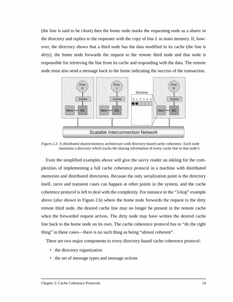
Chapter 2: Cache Coherence Protocols 14
(the line is said to be clean) then the home node marks the requesting node as a sharer in
the directory and replies to the requester with the copy of line L in main memory. If, how-
ever, the directory shows that a third node has the data modified in its cache (the line is
dirty), the home node forwards the request to the remote third node and that node is
responsible for retrieving the line from its cache and responding with the data. The remote
node must also send a message back to the home indicating the success of the transaction.
Even the simplified examples above will give the savvy reader an inkling for the com-
plexities of implementing a full cache coherence protocol in a machine with distributed
memories and distributed directories. Because the only serialization point is the directory
itself, races and transient cases can happen at other points in the system, and the cache
coherence protocol is left to deal with the complexity. For instance in the “3-hop” example
above (also shown in Figure 2.6) where the home node forwards the request to the dirty
remote third node, the desired cache line may no longer be present in the remote cache
when the forwarded request arrives. The dirty node may have written the desired cache
line back to the home node on its own. The cache coherence protocol has to “do the right
thing” in these cases—there is no such thing as being “almost coherent”.
There are two major components to every directory-based cache coherence protocol:
• the directory organization
• the set of message types and message actions
Figure 2.3. A distributed shared-memory architecture with directory-based cache coherence. Each node maintains a directory which tracks the sharing information of every cache line in that node’s
Directory
Proc0
Cache
NCMem
Proc1
Cache
NCMem
ProcN
Cache
NCMem
Scalable Interconnection Network
0 1 2 3 4 5
Chapter 2: Cache Coherence Protocols 15
The directory organization refers to the data structures used to store the directory informa-
tion and directly affects the number of bits used to store the sharing information for each
cache line. The memory required for the directory is a concern because it is “extra” mem-
ory that is not required by non-directory-based machines. The ratio of the directory mem-
ory to the total amount of memory is called the directory memory overhead. The designer
would like to keep the directory memory overhead as low as possible and would like it to
scale very slowly with machine size. The directory organization also has ramifications for
the performance of directory accesses since some directory data structures may require
more hardware to implement than others, have more state bits to check, or require tra-
versal of linked lists rather than more static data structures.
The directory organization holds the state of the cache coherence protocol, but the pro-
tocol must also send messages back and forth between nodes to communicate protocol
state changes, data requests, and data replies. Each protocol message sent over the net-
work has a type or opcode associated with it, and each node takes a specific action based
on the type of message it receives and the current state of the system. The set of message
actions include reading and updating the directory state as necessary, handling all possible
race conditions, transient states, and “corner cases” in the protocol, composing any neces-
sary response messages, and correctly managing the central resources of the machine,
such as virtual lanes in the network, in a deadlock-free manner. Because the actions of the
protocol are intimately related to the machine’s deadlock avoidance strategy, it is very
easy to design a protocol that will livelock or deadlock. It is much more complicated to
design and implement a high-performance protocol that is deadlock-free.
Variants of three major cache coherence protocols have been implemented in commer-
cial DSM machines, and other protocols have been proposed in the research community.
Each protocol varies in terms of directory organization (and therefore directory memory
overhead), the number and types of messages exchanged between nodes, the direct proto-
col processing overhead, and inherent scalability features. The next sections discuss a
range of directory-based cache coherence protocols, describe the advantages and disad-
vantages of each protocol, show some basic protocol transactions, and cite real machines
that implement each protocol.
Chapter 2: Cache Coherence Protocols 16
2.3 Bit-vector/Coarse-vector
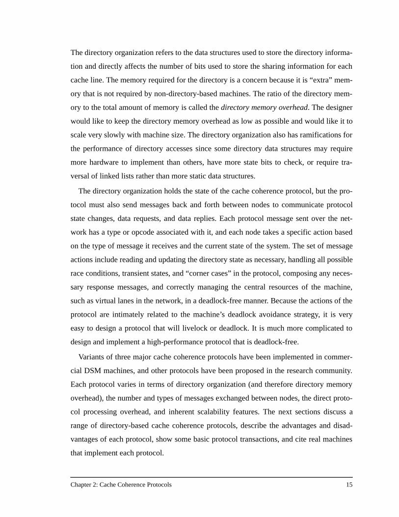
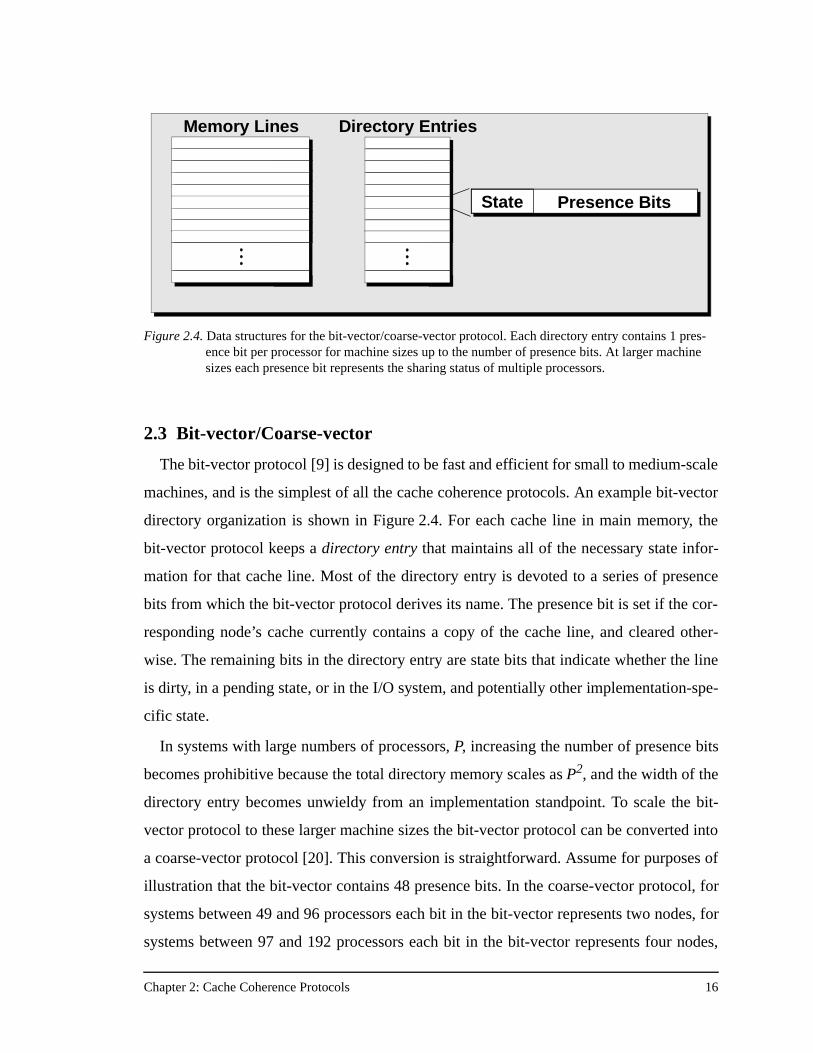
The bit-vector protocol [9] is designed to be fast and efficient for small to medium-scale
machines, and is the simplest of all the cache coherence protocols. An example bit-vector
directory organization is shown in Figure 2.4. For each cache line in main memory, the
bit-vector protocol keeps a directory entry that maintains all of the necessary state infor-
mation for that cache line. Most of the directory entry is devoted to a series of presence
bits from which the bit-vector protocol derives its name. The presence bit is set if the cor-
responding node’s cache currently contains a copy of the cache line, and cleared other-
wise. The remaining bits in the directory entry are state bits that indicate whether the line
is dirty, in a pending state, or in the I/O system, and potentially other implementation-spe-
cific state.
In systems with large numbers of processors, P, increasing the number of presence bits
becomes prohibitive because the total directory memory scales as P2, and the width of the
directory entry becomes unwieldy from an implementation standpoint. To scale the bit-
vector protocol to these larger machine sizes the bit-vector protocol can be converted into
a coarse-vector protocol [20]. This conversion is straightforward. Assume for purposes of
illustration that the bit-vector contains 48 presence bits. In the coarse-vector protocol, for
systems between 49 and 96 processors each bit in the bit-vector represents two nodes, for
systems between 97 and 192 processors each bit in the bit-vector represents four nodes,
Directory EntriesMemory Lines
State Presence Bits
Figure 2.4. Data structures for the bit-vector/coarse-vector protocol. Each directory entry contains 1 pres-ence bit per processor for machine sizes up to the number of presence bits. At larger machine sizes each presence bit represents the sharing status of multiple processors.
Chapter 2: Cache Coherence Protocols 17
and so on. The coarseness of the protocol is defined as the number of nodes each bit in the
bit-vector represents. The bit-vector protocol has a coarseness of one. With 48 presence
bits a 64-processor machine has a coarseness of two, and a 128-processor machine has a
coarseness of four. For the coarse-vector protocol, a presence bit is set if any of the nodes
represented by that bit are currently sharing the cache line.
The protocol transitions for the bit-vector/coarse-vector protocol are conceptually sim-
ple and very amenable to hardware implementation. Its simplicity is the main reason for
its popularity. The Stanford DASH multiprocessor [31] and the HaL-S1 [60] both imple-
ments a straight bit-vector protocol (the DASH machine only scales up to 64 processors,
and the HaL machine only scales to 16 processors). Although these machines implement
bit-vector at the directory level, they actually both have a built-in coarseness of four, since
each bit in the directory entry corresponds to a single node that is itself a 4-processor sym-
metric multiprocessor (SMP). In both these machines a snoopy protocol is used to main-
tain coherence within the cluster, and the bit-vector directory protocol maintains
coherence between clusters. The SGI Origin 2000 [30] implements a bit-vector/coarse-
vector protocol where the coarseness transitions immediately from one to eight above 128
processors. The next sections examine the bit-vector/coarse-vector protocol actions in the
common case for processor read and write requests that miss in the cache.
Bit-vector/Coarse-vector Read MissOn a processor cache read miss, a read request (GET) is forwarded to the home node for
that address. When the request arrives, the home node looks up the directory entry for that
cache line. If the directory shows the line to be uncached or to be cached read-only by any
number of processors, the bit-vector protocol action is the same, and is shown in
Figure 2.5. The home node simply sets the presence bit corresponding to the node number
of the requester, and responds to the read request with the data in main memory via a PUT
message. If however, the dirty bit is set in the directory entry, one and only one presence
bit must be set—that of the node which has the exclusive copy of the cache line. If the
dirty bit is set, the home forwards the read request to the owner of the cache line, as shown
in Figure 2.6. When the dirty remote node receives the forwarded read request, it retrieves
the dirty data from its cache, leaving the data in its cache in the shared state, and takes two
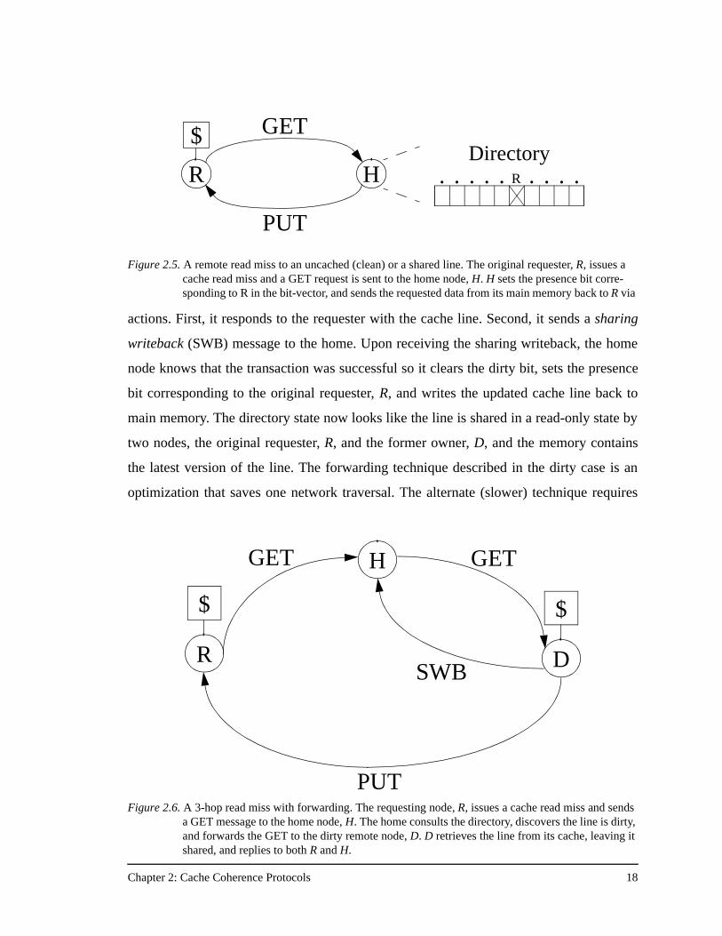
Chapter 2: Cache Coherence Protocols 18
actions. First, it responds to the requester with the cache line. Second, it sends a sharing
writeback (SWB) message to the home. Upon receiving the sharing writeback, the home
node knows that the transaction was successful so it clears the dirty bit, sets the presence
bit corresponding to the original requester, R, and writes the updated cache line back to
main memory. The directory state now looks like the line is shared in a read-only state by
two nodes, the original requester, R, and the former owner, D, and the memory contains
the latest version of the line. The forwarding technique described in the dirty case is an
optimization that saves one network traversal. The alternate (slower) technique requires
Figure 2.5. A remote read miss to an uncached (clean) or a shared line. The original requester, R, issues a cache read miss and a GET request is sent to the home node, H. H sets the presence bit corre-sponding to R in the bit-vector, and sends the requested data from its main memory back to R via
R
$
H
GET
PUT
R. . . .. . . . .Directory
R
$
H
D
$
GET
PUT
SWB
GET
Figure 2.6. A 3-hop read miss with forwarding. The requesting node, R, issues a cache read miss and sends a GET message to the home node, H. The home consults the directory, discovers the line is dirty, and forwards the GET to the dirty remote node, D. D retrieves the line from its cache, leaving it shared, and replies to both R and H.
Chapter 2: Cache Coherence Protocols 19
the home to send a message back to the original requester that tells it which node really
has the dirty data. Since implementing forwarding causes relatively little added complex-
ity, most protocols use the forwarding technique.
Bit-vector/Coarse-vector Write MissProcessor write requests are only marginally more complicated. On a write miss, a write
request is again sent to the home node. The home node consults the directory and handles
one of three main cases. In the first case, the line could be completely uncached in the sys-
tem. This is the simplest case. The home node just sets the dirty bit, sets the presence bit
corresponding to the requester, R, and sends a data reply with the cache line in main mem-
ory. Pictorially the transaction looks exactly like the read miss shown in Figure 2.5 with
the GET message replaced by a GETX (GET eXclusive) and the PUT message replaced
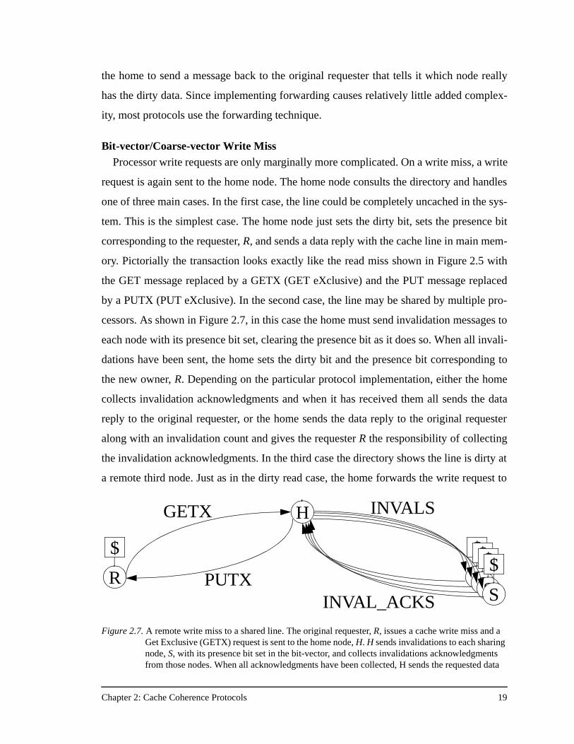
by a PUTX (PUT eXclusive). In the second case, the line may be shared by multiple pro-
cessors. As shown in Figure 2.7, in this case the home must send invalidation messages to
each node with its presence bit set, clearing the presence bit as it does so. When all invali-
dations have been sent, the home sets the dirty bit and the presence bit corresponding to
the new owner, R. Depending on the particular protocol implementation, either the home
collects invalidation acknowledgments and when it has received them all sends the data
reply to the original requester, or the home sends the data reply to the original requester
along with an invalidation count and gives the requester R the responsibility of collecting
the invalidation acknowledgments. In the third case the directory shows the line is dirty at
a remote third node. Just as in the dirty read case, the home forwards the write request to
R
$
H
S
$
INVAL_ACKS
GETX
S
$
S
$
S
$
INVALS
PUTX
Figure 2.7. A remote write miss to a shared line. The original requester, R, issues a cache write miss and a Get Exclusive (GETX) request is sent to the home node, H. H sends invalidations to each sharing node, S, with its presence bit set in the bit-vector, and collects invalidations acknowledgments from those nodes. When all acknowledgments have been collected, H sends the requested data
Chapter 2: Cache Coherence Protocols 20
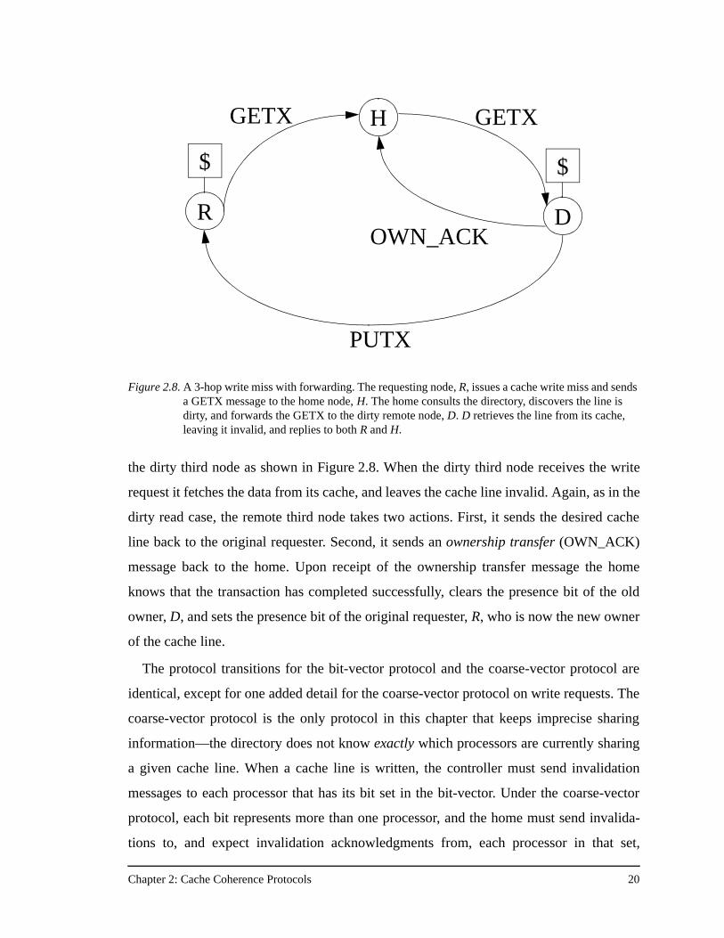
the dirty third node as shown in Figure 2.8. When the dirty third node receives the write
request it fetches the data from its cache, and leaves the cache line invalid. Again, as in the
dirty read case, the remote third node takes two actions. First, it sends the desired cache
line back to the original requester. Second, it sends an ownership transfer (OWN_ACK)
message back to the home. Upon receipt of the ownership transfer message the home
knows that the transaction has completed successfully, clears the presence bit of the old
owner, D, and sets the presence bit of the original requester, R, who is now the new owner
of the cache line.
The protocol transitions for the bit-vector protocol and the coarse-vector protocol are
identical, except for one added detail for the coarse-vector protocol on write requests. The
coarse-vector protocol is the only protocol in this chapter that keeps imprecise sharing
information—the directory does not know exactly which processors are currently sharing
a given cache line. When a cache line is written, the controller must send invalidation
messages to each processor that has its bit set in the bit-vector. Under the coarse-vector
protocol, each bit represents more than one processor, and the home must send invalida-
tions to, and expect invalidation acknowledgments from, each processor in that set,
Figure 2.8. A 3-hop write miss with forwarding. The requesting node, R, issues a cache write miss and sends a GETX message to the home node, H. The home consults the directory, discovers the line is dirty, and forwards the GETX to the dirty remote node, D. D retrieves the line from its cache, leaving it invalid, and replies to both R and H.
R
$
H
D
$
GETX
PUTX
OWN_ACK
GETX
Chapter 2: Cache Coherence Protocols 21
regardless of whether or not the processors were actually caching the line. This can cause
increased message traffic with respect to protocols that maintain precise sharing informa-
tion, and it is one of the issues considered in Chapter 6 when looking at protocol perfor-
mance on larger-scale machines.
Although it may result in increased invalidation traffic, the coarse-vector extension to
the bit-vector protocol keeps the directory memory overhead fixed by increasing the
coarseness as the protocol scales up to thousands of processing nodes. The overhead
remains fixed because the coarse-vector protocol adjusts its coarseness as the machine
size scales so that it always uses the same number of presence bits as the bit-vector proto-
col—each bit just represents a larger number of processors. Since the directory entry is the
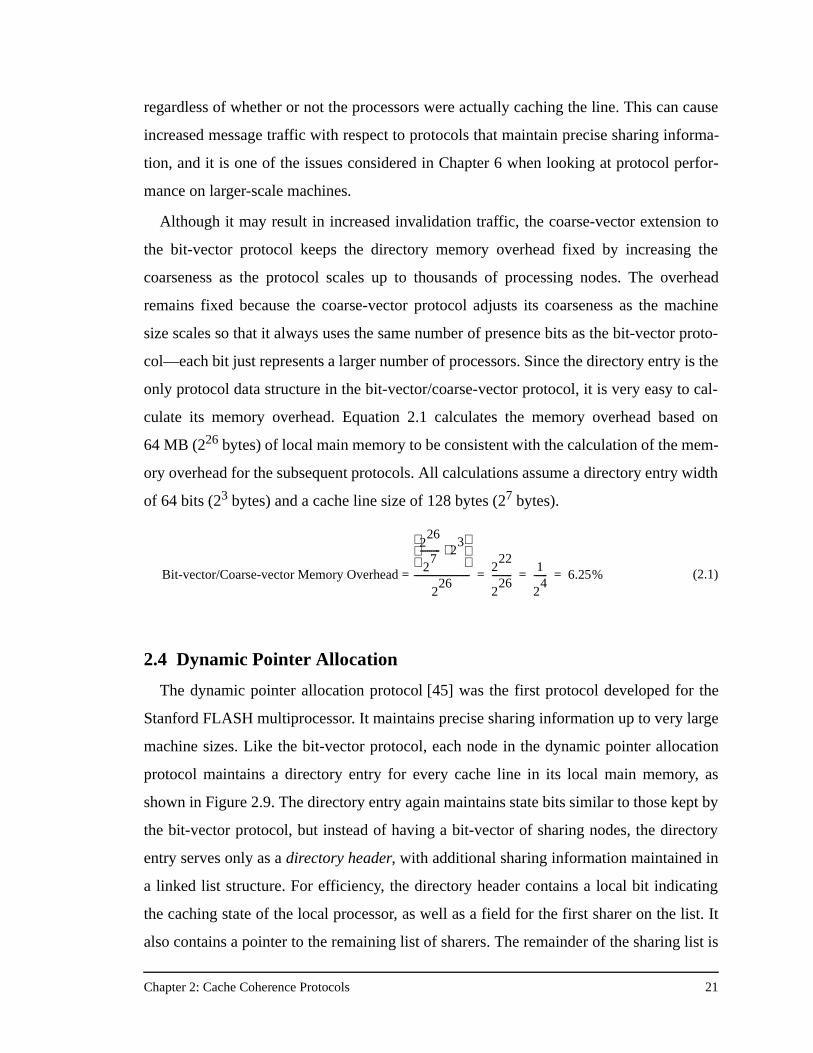
only protocol data structure in the bit-vector/coarse-vector protocol, it is very easy to cal-
culate its memory overhead. Equation 2.1 calculates the memory overhead based on
64 MB (226 bytes) of local main memory to be consistent with the calculation of the mem-
ory overhead for the subsequent protocols. All calculations assume a directory entry width
of 64 bits (23 bytes) and a cache line size of 128 bytes (27 bytes).
2.4 Dynamic Pointer Allocation
The dynamic pointer allocation protocol [45] was the first protocol developed for the
Stanford FLASH multiprocessor. It maintains precise sharing information up to very large
machine sizes. Like the bit-vector protocol, each node in the dynamic pointer allocation
protocol maintains a directory entry for every cache line in its local main memory, as
shown in Figure 2.9. The directory entry again maintains state bits similar to those kept by
the bit-vector protocol, but instead of having a bit-vector of sharing nodes, the directory
entry serves only as a directory header, with additional sharing information maintained in
a linked list structure. For efficiency, the directory header contains a local bit indicating
the caching state of the local processor, as well as a field for the first sharer on the list. It
also contains a pointer to the remaining list of sharers. The remainder of the sharing list is
(2.1)Bit-vector/Coarse-vector Memory Overhead =
226
27
--------- 23⋅
226
-------------------------2
22
226
---------1
24
------ 6.25%= = =
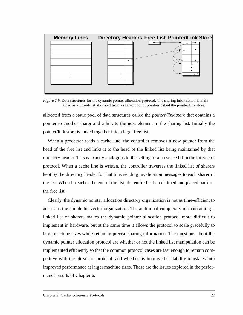
Chapter 2: Cache Coherence Protocols 22
allocated from a static pool of data structures called the pointer/link store that contains a
pointer to another sharer and a link to the next element in the sharing list. Initially the
pointer/link store is linked together into a large free list.
When a processor reads a cache line, the controller removes a new pointer from the
head of the free list and links it to the head of the linked list being maintained by that
directory header. This is exactly analogous to the setting of a presence bit in the bit-vector
protocol. When a cache line is written, the controller traverses the linked list of sharers
kept by the directory header for that line, sending invalidation messages to each sharer in
the list. When it reaches the end of the list, the entire list is reclaimed and placed back on
the free list.
Clearly, the dynamic pointer allocation directory organization is not as time-efficient to
access as the simple bit-vector organization. The additional complexity of maintaining a
linked list of sharers makes the dynamic pointer allocation protocol more difficult to
implement in hardware, but at the same time it allows the protocol to scale gracefully to
large machine sizes while retaining precise sharing information. The questions about the
dynamic pointer allocation protocol are whether or not the linked list manipulation can be
implemented efficiently so that the common protocol cases are fast enough to remain com-
petitive with the bit-vector protocol, and whether its improved scalability translates into
improved performance at larger machine sizes. These are the issues explored in the perfor-
mance results of Chapter 6.
Figure 2.9. Data structures for the dynamic pointer allocation protocol. The sharing information is main-tained as a linked-list allocated from a shared pool of pointers called the pointer/link store.
Directory Headers Pointer/Link StoreFree ListMemory Lines
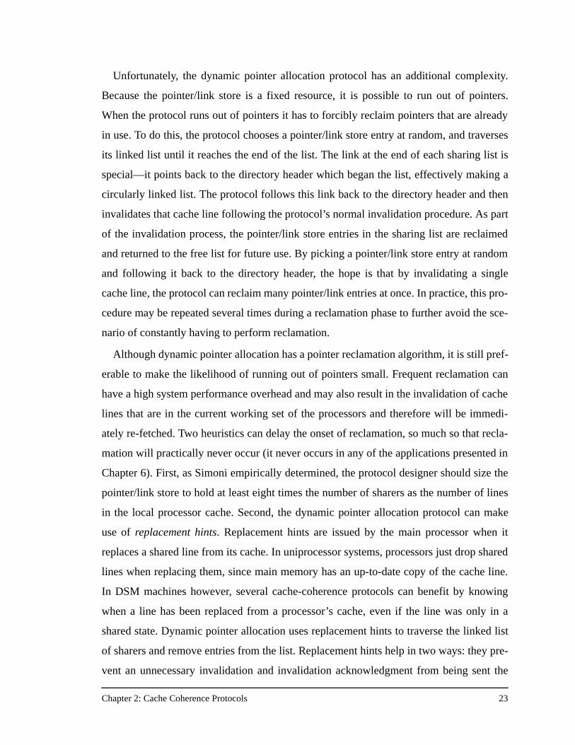
Chapter 2: Cache Coherence Protocols 23
Unfortunately, the dynamic pointer allocation protocol has an additional complexity.
Because the pointer/link store is a fixed resource, it is possible to run out of pointers.
When the protocol runs out of pointers it has to forcibly reclaim pointers that are already
in use. To do this, the protocol chooses a pointer/link store entry at random, and traverses
its linked list until it reaches the end of the list. The link at the end of each sharing list is
special—it points back to the directory header which began the list, effectively making a
circularly linked list. The protocol follows this link back to the directory header and then
invalidates that cache line following the protocol’s normal invalidation procedure. As part
of the invalidation process, the pointer/link store entries in the sharing list are reclaimed
and returned to the free list for future use. By picking a pointer/link store entry at random
and following it back to the directory header, the hope is that by invalidating a single
cache line, the protocol can reclaim many pointer/link entries at once. In practice, this pro-
cedure may be repeated several times during a reclamation phase to further avoid the sce-
nario of constantly having to perform reclamation.
Although dynamic pointer allocation has a pointer reclamation algorithm, it is still pref-
erable to make the likelihood of running out of pointers small. Frequent reclamation can
have a high system performance overhead and may also result in the invalidation of cache
lines that are in the current working set of the processors and therefore will be immedi-
ately re-fetched. Two heuristics can delay the onset of reclamation, so much so that recla-
mation will practically never occur (it never occurs in any of the applications presented in
Chapter 6). First, as Simoni empirically determined, the protocol designer should size the
pointer/link store to hold at least eight times the number of sharers as the number of lines
in the local processor cache. Second, the dynamic pointer allocation protocol can make
use of replacement hints. Replacement hints are issued by the main processor when it
replaces a shared line from its cache. In uniprocessor systems, processors just drop shared
lines when replacing them, since main memory has an up-to-date copy of the cache line.
In DSM machines however, several cache-coherence protocols can benefit by knowing
when a line has been replaced from a processor’s cache, even if the line was only in a
shared state. Dynamic pointer allocation uses replacement hints to traverse the linked list
of sharers and remove entries from the list. Replacement hints help in two ways: they pre-
vent an unnecessary invalidation and invalidation acknowledgment from being sent the
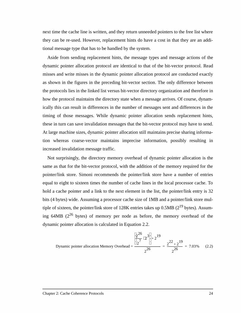
Chapter 2: Cache Coherence Protocols 24
next time the cache line is written, and they return unneeded pointers to the free list where
they can be re-used. However, replacement hints do have a cost in that they are an addi-
tional message type that has to be handled by the system.
Aside from sending replacement hints, the message types and message actions of the
dynamic pointer allocation protocol are identical to that of the bit-vector protocol. Read
misses and write misses in the dynamic pointer allocation protocol are conducted exactly
as shown in the figures in the preceding bit-vector section. The only difference between
the protocols lies in the linked list versus bit-vector directory organization and therefore in
how the protocol maintains the directory state when a message arrives. Of course, dynam-
ically this can result in differences in the number of messages sent and differences in the
timing of those messages. While dynamic pointer allocation sends replacement hints,
these in turn can save invalidation messages that the bit-vector protocol may have to send.
At large machine sizes, dynamic pointer allocation still maintains precise sharing informa-
tion whereas coarse-vector maintains imprecise information, possibly resulting in
increased invalidation message traffic.
Not surprisingly, the directory memory overhead of dynamic pointer allocation is the
same as that for the bit-vector protocol, with the addition of the memory required for the
pointer/link store. Simoni recommends the pointer/link store have a number of entries
equal to eight to sixteen times the number of cache lines in the local processor cache. To
hold a cache pointer and a link to the next element in the list, the pointer/link entry is 32
bits (4 bytes) wide. Assuming a processor cache size of 1MB and a pointer/link store mul-
tiple of sixteen, the pointer/link store of 128K entries takes up 0.5MB (219 bytes). Assum-
ing 64MB (226 bytes) of memory per node as before, the memory overhead of the
dynamic pointer allocation is calculated in Equation 2.2.
(2.2)Dynamic pointer allocation Memory Overhead =
226
27
--------- 23⋅
219
+
226
----------------------------------------2
222
19+
226
------------------------ 7.03%= =
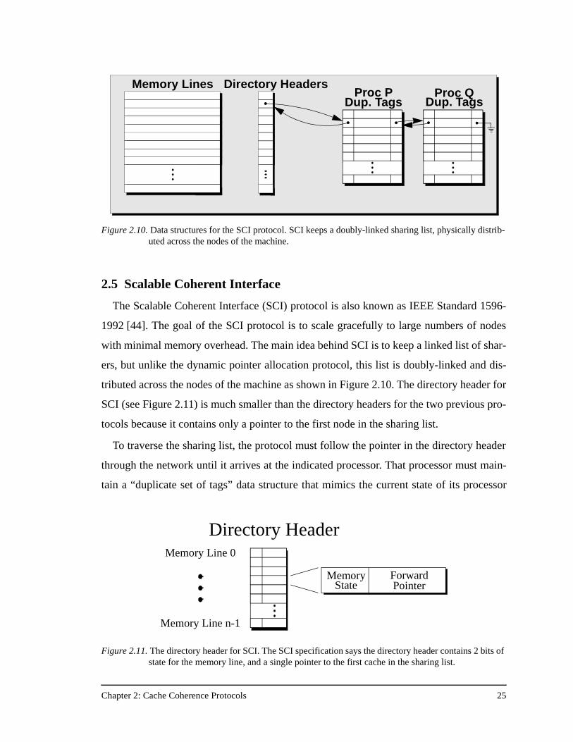
Chapter 2: Cache Coherence Protocols 25
2.5 Scalable Coherent Interface
The Scalable Coherent Interface (SCI) protocol is also known as IEEE Standard 1596-
1992 [44]. The goal of the SCI protocol is to scale gracefully to large numbers of nodes
with minimal memory overhead. The main idea behind SCI is to keep a linked list of shar-
ers, but unlike the dynamic pointer allocation protocol, this list is doubly-linked and dis-
tributed across the nodes of the machine as shown in Figure 2.10. The directory header for
SCI (see Figure 2.11) is much smaller than the directory headers for the two previous pro-
tocols because it contains only a pointer to the first node in the sharing list.
To traverse the sharing list, the protocol must follow the pointer in the directory header
through the network until it arrives at the indicated processor. That processor must main-
tain a “duplicate set of tags” data structure that mimics the current state of its processor
Directory HeadersMemory LinesProc P Proc Q
Dup. Tags Dup. Tags
Figure 2.10. Data structures for the SCI protocol. SCI keeps a doubly-linked sharing list, physically distrib-uted across the nodes of the machine.
Figure 2.11. The directory header for SCI. The SCI specification says the directory header contains 2 bits of state for the memory line, and a single pointer to the first cache in the sharing list.
Directory HeaderMemory Line 0
Memory Line n-1
Memory ForwardPointerState
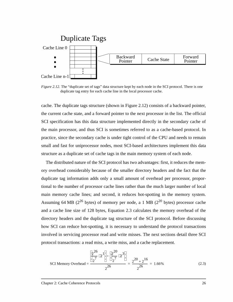
Chapter 2: Cache Coherence Protocols 26
cache. The duplicate tags structure (shown in Figure 2.12) consists of a backward pointer,
the current cache state, and a forward pointer to the next processor in the list. The official
SCI specification has this data structure implemented directly in the secondary cache of
the main processor, and thus SCI is sometimes referred to as a cache-based protocol. In
practice, since the secondary cache is under tight control of the CPU and needs to remain
small and fast for uniprocessor nodes, most SCI-based architectures implement this data
structure as a duplicate set of cache tags in the main memory system of each node.
The distributed nature of the SCI protocol has two advantages: first, it reduces the mem-
ory overhead considerably because of the smaller directory headers and the fact that the
duplicate tag information adds only a small amount of overhead per processor, propor-
tional to the number of processor cache lines rather than the much larger number of local
main memory cache lines; and second, it reduces hot-spotting in the memory system.
Assuming 64 MB (226 bytes) of memory per node, a 1 MB (220 bytes) processor cache
and a cache line size of 128 bytes, Equation 2.3 calculates the memory overhead of the
directory headers and the duplicate tag structure of the SCI protocol. Before discussing
how SCI can reduce hot-spotting, it is necessary to understand the protocol transactions
involved in servicing processor read and write misses. The next sections detail three SCI
protocol transactions: a read miss, a write miss, and a cache replacement.
Figure 2.12. The “duplicate set of tags” data structure kept by each node in the SCI protocol. There is one duplicate tag entry for each cache line in the local processor cache.
Duplicate TagsCache Line 0
Cache Line n-1
BackwardPointer Cache State
ForwardPointer
(2.3)SCI Memory Overhead =
226
27
--------- 21⋅
2
20
27
--------- 23⋅
+
226
--------------------------------------------------------2
202
16+
226
------------------------ 1.66%= =
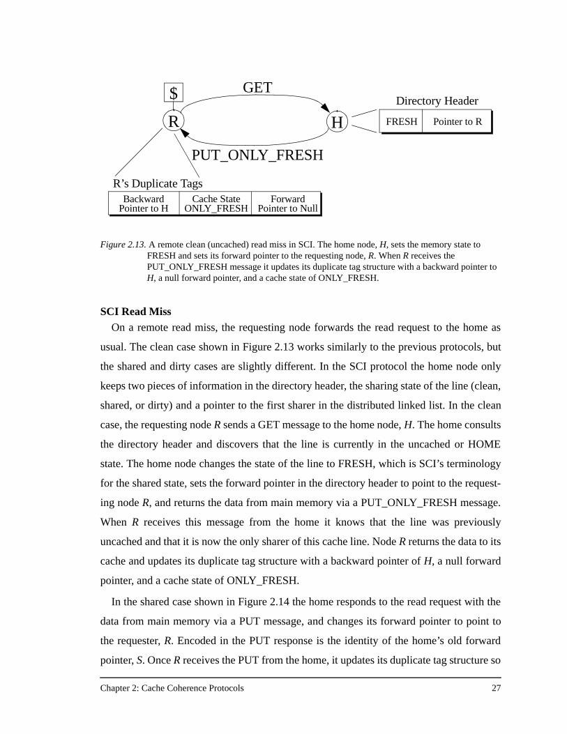
Chapter 2: Cache Coherence Protocols 27
SCI Read MissOn a remote read miss, the requesting node forwards the read request to the home as
usual. The clean case shown in Figure 2.13 works similarly to the previous protocols, but
the shared and dirty cases are slightly different. In the SCI protocol the home node only
keeps two pieces of information in the directory header, the sharing state of the line (clean,
shared, or dirty) and a pointer to the first sharer in the distributed linked list. In the clean
case, the requesting node R sends a GET message to the home node, H. The home consults
the directory header and discovers that the line is currently in the uncached or HOME
state. The home node changes the state of the line to FRESH, which is SCI’s terminology
for the shared state, sets the forward pointer in the directory header to point to the request-
ing node R, and returns the data from main memory via a PUT_ONLY_FRESH message.
When R receives this message from the home it knows that the line was previously
uncached and that it is now the only sharer of this cache line. Node R returns the data to its
cache and updates its duplicate tag structure with a backward pointer of H, a null forward
pointer, and a cache state of ONLY_FRESH.
In the shared case shown in Figure 2.14 the home responds to the read request with the
data from main memory via a PUT message, and changes its forward pointer to point to
the requester, R. Encoded in the PUT response is the identity of the home’s old forward
pointer, S. Once R receives the PUT from the home, it updates its duplicate tag structure so
R
$
H
GET
PUT_ONLY_FRESH
Figure 2.13. A remote clean (uncached) read miss in SCI. The home node, H, sets the memory state to FRESH and sets its forward pointer to the requesting node, R. When R receives the PUT_ONLY_FRESH message it updates its duplicate tag structure with a backward pointer to H, a null forward pointer, and a cache state of ONLY_FRESH.
FRESH Pointer to R
BackwardPointer to H
Cache State ForwardPointer to Null
Directory Header
R’s Duplicate Tags
ONLY_FRESH
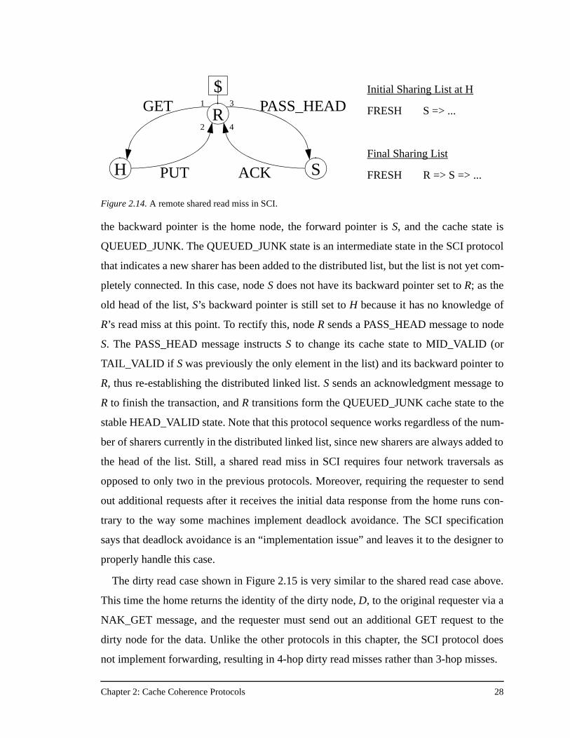
Chapter 2: Cache Coherence Protocols 28
the backward pointer is the home node, the forward pointer is S, and the cache state is
QUEUED_JUNK. The QUEUED_JUNK state is an intermediate state in the SCI protocol
that indicates a new sharer has been added to the distributed list, but the list is not yet com-
pletely connected. In this case, node S does not have its backward pointer set to R; as the
old head of the list, S’s backward pointer is still set to H because it has no knowledge of
R’s read miss at this point. To rectify this, node R sends a PASS_HEAD message to node
S. The PASS_HEAD message instructs S to change its cache state to MID_VALID (or
TAIL_VALID if S was previously the only element in the list) and its backward pointer to
R, thus re-establishing the distributed linked list. S sends an acknowledgment message to
R to finish the transaction, and R transitions form the QUEUED_JUNK cache state to the
stable HEAD_VALID state. Note that this protocol sequence works regardless of the num-
ber of sharers currently in the distributed linked list, since new sharers are always added to
the head of the list. Still, a shared read miss in SCI requires four network traversals as
opposed to only two in the previous protocols. Moreover, requiring the requester to send
out additional requests after it receives the initial data response from the home runs con-
trary to the way some machines implement deadlock avoidance. The SCI specification
says that deadlock avoidance is an “implementation issue” and leaves it to the designer to
properly handle this case.
The dirty read case shown in Figure 2.15 is very similar to the shared read case above.
This time the home returns the identity of the dirty node, D, to the original requester via a
NAK_GET message, and the requester must send out an additional GET request to the
dirty node for the data. Unlike the other protocols in this chapter, the SCI protocol does
not implement forwarding, resulting in 4-hop dirty read misses rather than 3-hop misses.
Figure 2.14. A remote shared read miss in SCI.
R
$
H
GET
PUT S
PASS_HEAD
ACK
1
2
3
4
Initial Sharing List at H
FRESH S => ...
Final Sharing List
FRESH R => S => ...
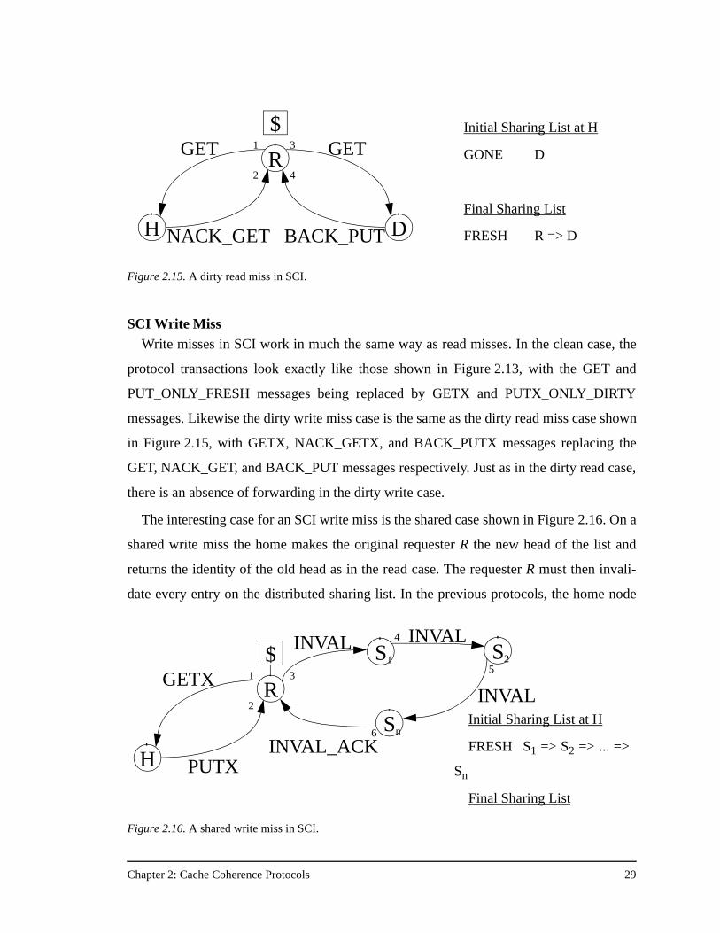
Chapter 2: Cache Coherence Protocols 29
SCI Write MissWrite misses in SCI work in much the same way as read misses. In the clean case, the
protocol transactions look exactly like those shown in Figure 2.13, with the GET and
PUT_ONLY_FRESH messages being replaced by GETX and PUTX_ONLY_DIRTY
messages. Likewise the dirty write miss case is the same as the dirty read miss case shown
in Figure 2.15, with GETX, NACK_GETX, and BACK_PUTX messages replacing the
GET, NACK_GET, and BACK_PUT messages respectively. Just as in the dirty read case,
there is an absence of forwarding in the dirty write case.
The interesting case for an SCI write miss is the shared case shown in Figure 2.16. On a
shared write miss the home makes the original requester R the new head of the list and
returns the identity of the old head as in the read case. The requester R must then invali-
date every entry on the distributed sharing list. In the previous protocols, the home node
Figure 2.15. A dirty read miss in SCI.
R
$
H
GET
NACK_GET D
GET
BACK_PUT
1
2
3
4
Initial Sharing List at H
GONE D
Final Sharing List
FRESH R => D
Figure 2.16. A shared write miss in SCI.
R
$
H
GETX
PUTX
S1
1
2
3
4
Initial Sharing List at H
FRESH S1 => S2 => ... =>
Sn
Final Sharing List
Sn
S2INVAL INVAL
INVAL
5
6
INVAL_ACK
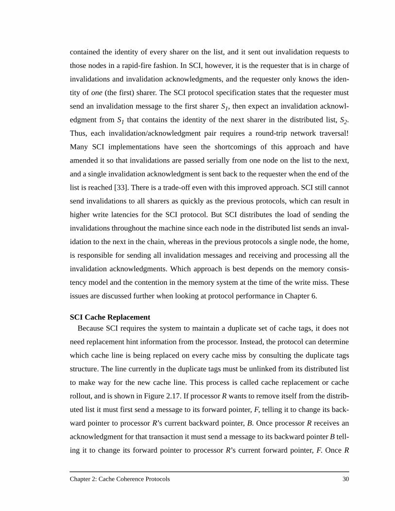
Chapter 2: Cache Coherence Protocols 30
contained the identity of every sharer on the list, and it sent out invalidation requests to
those nodes in a rapid-fire fashion. In SCI, however, it is the requester that is in charge of
invalidations and invalidation acknowledgments, and the requester only knows the iden-
tity of one (the first) sharer. The SCI protocol specification states that the requester must
send an invalidation message to the first sharer S1, then expect an invalidation acknowl-
edgment from S1 that contains the identity of the next sharer in the distributed list, S2.
Thus, each invalidation/acknowledgment pair requires a round-trip network traversal!
Many SCI implementations have seen the shortcomings of this approach and have
amended it so that invalidations are passed serially from one node on the list to the next,
and a single invalidation acknowledgment is sent back to the requester when the end of the
list is reached [33]. There is a trade-off even with this improved approach. SCI still cannot
send invalidations to all sharers as quickly as the previous protocols, which can result in
higher write latencies for the SCI protocol. But SCI distributes the load of sending the
invalidations throughout the machine since each node in the distributed list sends an inval-
idation to the next in the chain, whereas in the previous protocols a single node, the home,
is responsible for sending all invalidation messages and receiving and processing all the
invalidation acknowledgments. Which approach is best depends on the memory consis-
tency model and the contention in the memory system at the time of the write miss. These
issues are discussed further when looking at protocol performance in Chapter 6.
SCI Cache ReplacementBecause SCI requires the system to maintain a duplicate set of cache tags, it does not
need replacement hint information from the processor. Instead, the protocol can determine
which cache line is being replaced on every cache miss by consulting the duplicate tags
structure. The line currently in the duplicate tags must be unlinked from its distributed list
to make way for the new cache line. This process is called cache replacement or cache
rollout, and is shown in Figure 2.17. If processor R wants to remove itself from the distrib-
uted list it must first send a message to its forward pointer, F, telling it to change its back-
ward pointer to processor R’s current backward pointer, B. Once processor R receives an
acknowledgment for that transaction it must send a message to its backward pointer B tell-
ing it to change its forward pointer to processor R’s current forward pointer, F. Once R
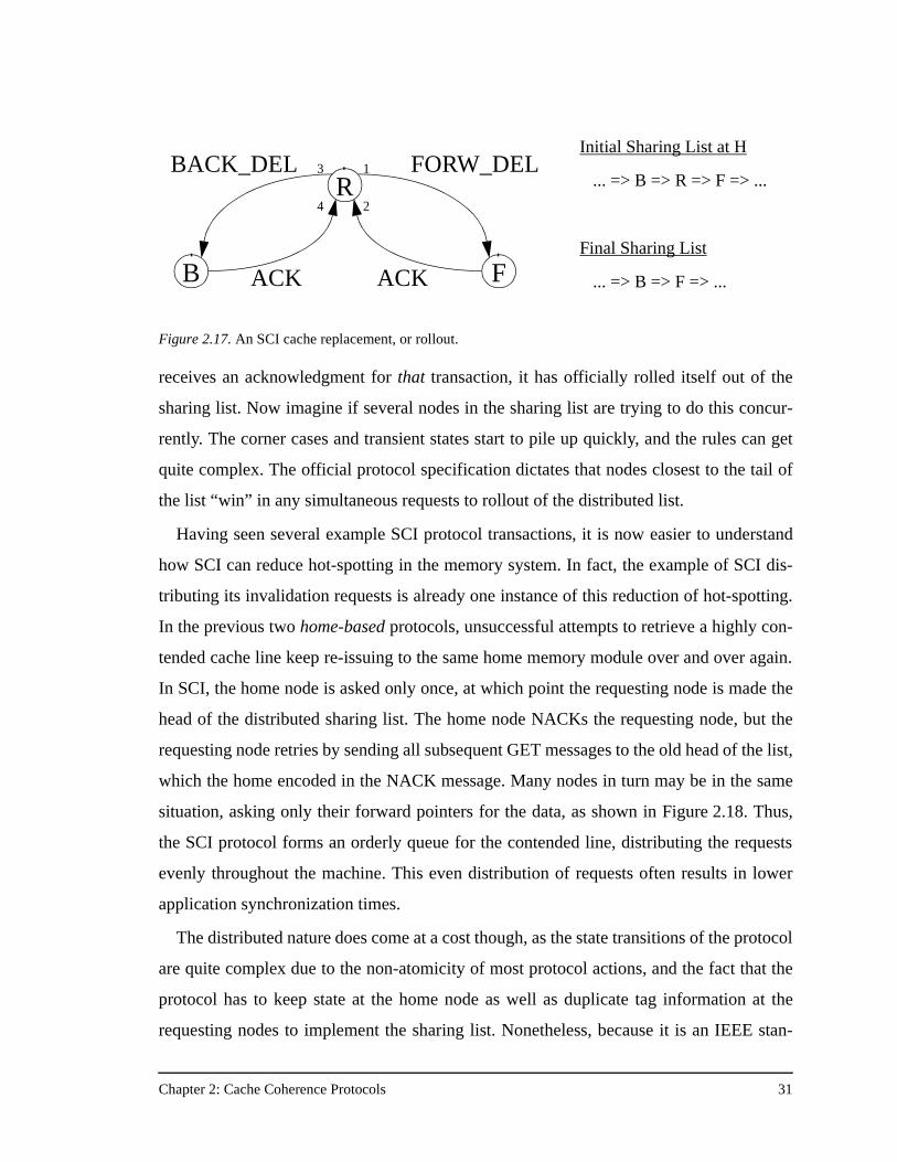
Chapter 2: Cache Coherence Protocols 31
receives an acknowledgment for that transaction, it has officially rolled itself out of the
sharing list. Now imagine if several nodes in the sharing list are trying to do this concur-
rently. The corner cases and transient states start to pile up quickly, and the rules can get
quite complex. The official protocol specification dictates that nodes closest to the tail of
the list “win” in any simultaneous requests to rollout of the distributed list.
Having seen several example SCI protocol transactions, it is now easier to understand
how SCI can reduce hot-spotting in the memory system. In fact, the example of SCI dis-
tributing its invalidation requests is already one instance of this reduction of hot-spotting.
In the previous two home-based protocols, unsuccessful attempts to retrieve a highly con-
tended cache line keep re-issuing to the same home memory module over and over again.
In SCI, the home node is asked only once, at which point the requesting node is made the
head of the distributed sharing list. The home node NACKs the requesting node, but the
requesting node retries by sending all subsequent GET messages to the old head of the list,
which the home encoded in the NACK message. Many nodes in turn may be in the same
situation, asking only their forward pointers for the data, as shown in Figure 2.18. Thus,
the SCI protocol forms an orderly queue for the contended line, distributing the requests
evenly throughout the machine. This even distribution of requests often results in lower
application synchronization times.
The distributed nature does come at a cost though, as the state transitions of the protocol
are quite complex due to the non-atomicity of most protocol actions, and the fact that the
protocol has to keep state at the home node as well as duplicate tag information at the
requesting nodes to implement the sharing list. Nonetheless, because it is an IEEE stan-
Figure 2.17. An SCI cache replacement, or rollout.
R
B
BACK_DEL
ACK F
FORW_DEL
ACK
3
4
1
2
Initial Sharing List at H
... => B => R => F => ...
Final Sharing List
... => B => F => ...
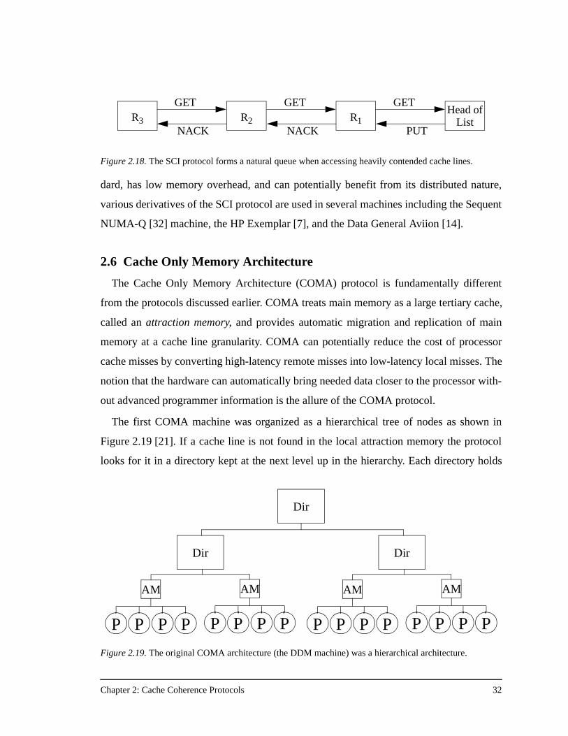
Chapter 2: Cache Coherence Protocols 32
dard, has low memory overhead, and can potentially benefit from its distributed nature,
various derivatives of the SCI protocol are used in several machines including the Sequent
NUMA-Q [32] machine, the HP Exemplar [7], and the Data General Aviion [14].
2.6 Cache Only Memory Architecture
The Cache Only Memory Architecture (COMA) protocol is fundamentally different
from the protocols discussed earlier. COMA treats main memory as a large tertiary cache,
called an attraction memory, and provides automatic migration and replication of main
memory at a cache line granularity. COMA can potentially reduce the cost of processor
cache misses by converting high-latency remote misses into low-latency local misses. The
notion that the hardware can automatically bring needed data closer to the processor with-
out advanced programmer information is the allure of the COMA protocol.
The first COMA machine was organized as a hierarchical tree of nodes as shown in
Figure 2.19 [21]. If a cache line is not found in the local attraction memory the protocol
looks for it in a directory kept at the next level up in the hierarchy. Each directory holds
Figure 2.18. The SCI protocol forms a natural queue when accessing heavily contended cache lines.
R3 R1R2Head of
List
GET
NACK
GET
PUT
GET
NACK
Figure 2.19. The original COMA architecture (the DDM machine) was a hierarchical architecture.
P
AM
P P P P
AM
P P P
Dir
Dir
P
AM
P P P P
AM
P P P
Dir
Chapter 2: Cache Coherence Protocols 33
information only for the processors beneath it in the hierarchy, and thus a single cache
miss may require several directory lookups at various points in the tree. Once a directory
locates the requested cache line, it forwards the request down the tree to the attraction
memory containing the data. The hierarchical directory structure of this COMA imple-
mentation causes the root of the directory tree to become a bottleneck, and the multiple
directory lookups yield poor performance as the machine size scales.
A second version of COMA, called flat COMA or COMA-F [53] assigns a static home
for the directory entries of each cache line just as in the previous protocols. If the cache
line is not in the local attraction memory, the statically assigned home is immediately con-
sulted to find out where the data resides. COMA-F removes the disadvantages of the hier-
archical directory structure, generally performs better [53], and makes it possible to
implement COMA on a traditional DSM architecture. It is the COMA-F protocol that is
presented in this section and the remainder of this text, and for brevity it is referred to sim-
ply as COMA.
Unlike the other protocols, COMA reserves extra memory on each node to act as an
additional memory cache for remote data. COMA needs extra memory to efficiently sup-
port cache line replication. Without extra memory, COMA could only migrate data, since
any new data placed in one attraction memory would displace the last remaining copy of
another cache line. The last remaining copy of a cache line is called the master copy. With
the addition of reserved memory, the attraction memory is just a large cache, and like the
processor’s cache it does not always have to send a message when one of its cache lines is
displaced. The attraction memory need only take action if it is replacing a master copy of
the cache line. All copies of the line that are not master copies can be displaced without
requiring further action by the protocol. To displace a master copy, a node first sends a
replacement message to the home node. It is the home node that has the responsibility to
find a new node for the master copy. The best place to try initially is the node which just
sent the data to the requesting node that caused this master copy to be displaced (see
Figure 2.20). That node likely has “room” for data at the proper location in its attraction
memory since it just surrendered a cache line that mapped there.
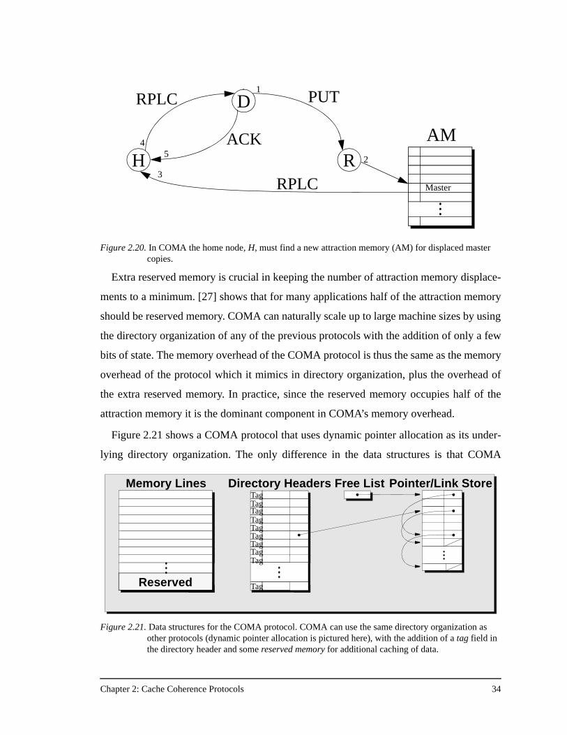
Chapter 2: Cache Coherence Protocols 34
Extra reserved memory is crucial in keeping the number of attraction memory displace-
ments to a minimum. [27] shows that for many applications half of the attraction memory
should be reserved memory. COMA can naturally scale up to large machine sizes by using
the directory organization of any of the previous protocols with the addition of only a few
bits of state. The memory overhead of the COMA protocol is thus the same as the memory
overhead of the protocol which it mimics in directory organization, plus the overhead of
the extra reserved memory. In practice, since the reserved memory occupies half of the
attraction memory it is the dominant component in COMA’s memory overhead.
Figure 2.21 shows a COMA protocol that uses dynamic pointer allocation as its under-
lying directory organization. The only difference in the data structures is that COMA
Figure 2.20. In COMA the home node, H, must find a new attraction memory (AM) for displaced master copies.
D
H
RPLC
ACKR
PUT
45
1
3
AM
Master
2
RPLC
Directory Headers Pointer/Link StoreFree ListMemory Lines
Reserved
Figure 2.21. Data structures for the COMA protocol. COMA can use the same directory organization as other protocols (dynamic pointer allocation is pictured here), with the addition of a tag field in the directory header and some reserved memory for additional caching of data.
TagTagTagTagTagTagTag
Tag
Tag
Tag
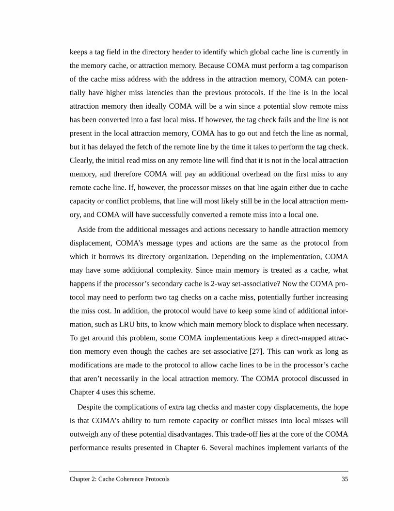
Chapter 2: Cache Coherence Protocols 35
keeps a tag field in the directory header to identify which global cache line is currently in
the memory cache, or attraction memory. Because COMA must perform a tag comparison
of the cache miss address with the address in the attraction memory, COMA can poten-
tially have higher miss latencies than the previous protocols. If the line is in the local
attraction memory then ideally COMA will be a win since a potential slow remote miss
has been converted into a fast local miss. If however, the tag check fails and the line is not
present in the local attraction memory, COMA has to go out and fetch the line as normal,
but it has delayed the fetch of the remote line by the time it takes to perform the tag check.
Clearly, the initial read miss on any remote line will find that it is not in the local attraction
memory, and therefore COMA will pay an additional overhead on the first miss to any
remote cache line. If, however, the processor misses on that line again either due to cache
capacity or conflict problems, that line will most likely still be in the local attraction mem-
ory, and COMA will have successfully converted a remote miss into a local one.
Aside from the additional messages and actions necessary to handle attraction memory
displacement, COMA’s message types and actions are the same as the protocol from
which it borrows its directory organization. Depending on the implementation, COMA
may have some additional complexity. Since main memory is treated as a cache, what
happens if the processor’s secondary cache is 2-way set-associative? Now the COMA pro-
tocol may need to perform two tag checks on a cache miss, potentially further increasing
the miss cost. In addition, the protocol would have to keep some kind of additional infor-
mation, such as LRU bits, to know which main memory block to displace when necessary.
To get around this problem, some COMA implementations keep a direct-mapped attrac-
tion memory even though the caches are set-associative [27]. This can work as long as
modifications are made to the protocol to allow cache lines to be in the processor’s cache
that aren’t necessarily in the local attraction memory. The COMA protocol discussed in
Chapter 4 uses this scheme.
Despite the complications of extra tag checks and master copy displacements, the hope
is that COMA’s ability to turn remote capacity or conflict misses into local misses will
outweigh any of these potential disadvantages. This trade-off lies at the core of the COMA
performance results presented in Chapter 6. Several machines implement variants of the
Chapter 2: Cache Coherence Protocols 36
COMA protocol including the Swedish Institute of Computer Science’s Data Diffusion
Machine [21], and the KSR1 [8] from Kendall Square Research.
2.7 Which Protocol is Best?
Having discussed four intriguing cache coherence protocols, the natural question that
arises is: Which protocol is best? In the past this has proved a difficult question to answer.
Often the virtues of each protocol are argued with an almost religious fervor by their sup-
porters. The question is problematic because traditionally any given cache coherence pro-
tocol implementation was tied to a specific machine, and vice versa. Since each
multiprocessor hard-wired a cache coherence protocol, comparing protocols meant com-
paring performance across different machines. This approach is doomed since differences
in machine architecture or other implementation artifacts inevitably obfuscate the protocol
comparison.
Fortunately, there is a now a solution to the difficult problem of comparing coherence
protocols. The solution lies in the flexibility of the Stanford FLASH multiprocessor. Using
the FLASH multiprocessor as an experimental environment, it is now possible to put some
quantitative reasoning behind the search for the optimal cache coherence protocol, and
help answer the following questions:
• Is there a single optimal protocol for all applications?
• Does the optimal protocol vary with machine size?
• Does the optimal protocol change with application optimization level?
• Does the optimal protocol change with cache size?
• Can a single architecture achieve robust performance across a wide range of machine sizes and application characteristics?
The next chapter details the FLASH machine and its protocol environment.
Chapter 3: FLASH Architecture 37
Chapter 3
FLASH Architecture
To understand why FLASH offers the perfect experimental vehicle for coherence proto-
col comparisons, it is necessary to first discuss the FLASH architecture as well as the
micro-architecture of the FLASH node controller. This chapter begins with the FLASH
design rationale and follows with a description of the FLASH node. Particularly high-
lighted are elements of the FLASH architecture that support a flexible communication
protocol environment or aid in the deadlock avoidance strategy of the machine. A crucial
part of this performance study is that the protocols discussed here are full-fledged proto-
cols that run on a real machine and therefore must deal with all the real-world problems
encountered by a general-purpose multiprocessor architecture. In the context of the
FLASH multiprocessor, this chapter discusses the centralized resource and deadlock
avoidance issues that each protocol must handle in addition to managing the directory
state of cache lines in the system.
3.1 An Argument for Flexibility
The previous chapter described four vastly different cache coherence protocols, ranging
from the simple bit-vector/coarse-vector protocol to very complex protocols like SCI and
COMA. While the bit-vector protocol is amenable to hardware implementation in finite
state machines, the task of implementing all-hardware SCI and COMA protocols is much
more daunting. Not only would the more complex protocols require more hardware
resources, but they would also be more difficult to debug and verify. In machines with
fixed, hard-wired protocols, the ability to verify the correctness of the protocol is a critical
factor in the choice of protocol. If the cache coherence protocol is incorrect, the machine
will simply be unstable. A machine is either cache-coherent, or it isn’t.
For this reason, commercial DSM machines usually employ the bit-vector protocol
because it is the simplest, or the SCI protocol because the IEEE has made it a standard and
ensures designers that the protocol is correct as long as they adhere to that standard.
Unfortunately, in practice it is difficult to verify a hardware implementation of either the
bit-vector or the SCI protocol. In addition, there is the larger issue of which protocol is the
Chapter 3: FLASH Architecture 38
best protocol anyway? The scalability issues of the four protocols described in Chapter 2
are simply not well understood. The robustness of the protocols over a wide range of
machine sizes, application characteristics, and architectural parameters is an open ques-
tion, and the main focus of this research.
Rather than fix the cache coherence protocol in hardware finite state machines at design
time, an alternative approach is to design a flexible, programmable node controller archi-
tecture that implements the coherence protocol in software. This was precisely the
approach taken by Sequent when designing their SCI-based NUMA-Q machine.
Figure 3.1 shows the cache state diagram for the Sequent SCI protocol. The details are not
important—note only that it is extraordinarily complicated! The SCI protocol is compli-
cated enough that one could argue the best way to implement SCI is in a programmable
environment where debugging, verification, and future protocol optimizations are easier
than in an all-hardware approach.
The difficulty with designing programmable node controllers is doing so without sacri-
ficing the performance of an all-hardware solution. This was the primary goal of the Stan-
ford FLASH multiprocessor. The FLASH approach takes flexibility one step further and
embeds in the node controller a protocol processor capable of running multiple cache
coherence protocols. This flexibility allows the use of FLASH to explore the performance
impact of multiple cache coherence protocols on the same underlying architecture. The
next sections describe the FLASH node and the node controller architecture in detail.
3.2 FLASH and MAGIC Architecture
Figure 3.2 shows a high-level overview of a FLASH node. Each node consists of a
MIPS R10000 processor and its secondary cache, a portion of the machine’s physically
distributed main memory, and the FLASH node controller called MAGIC (Memory And
General Interconnect Controller). MAGIC is a flexible, programmable node controller
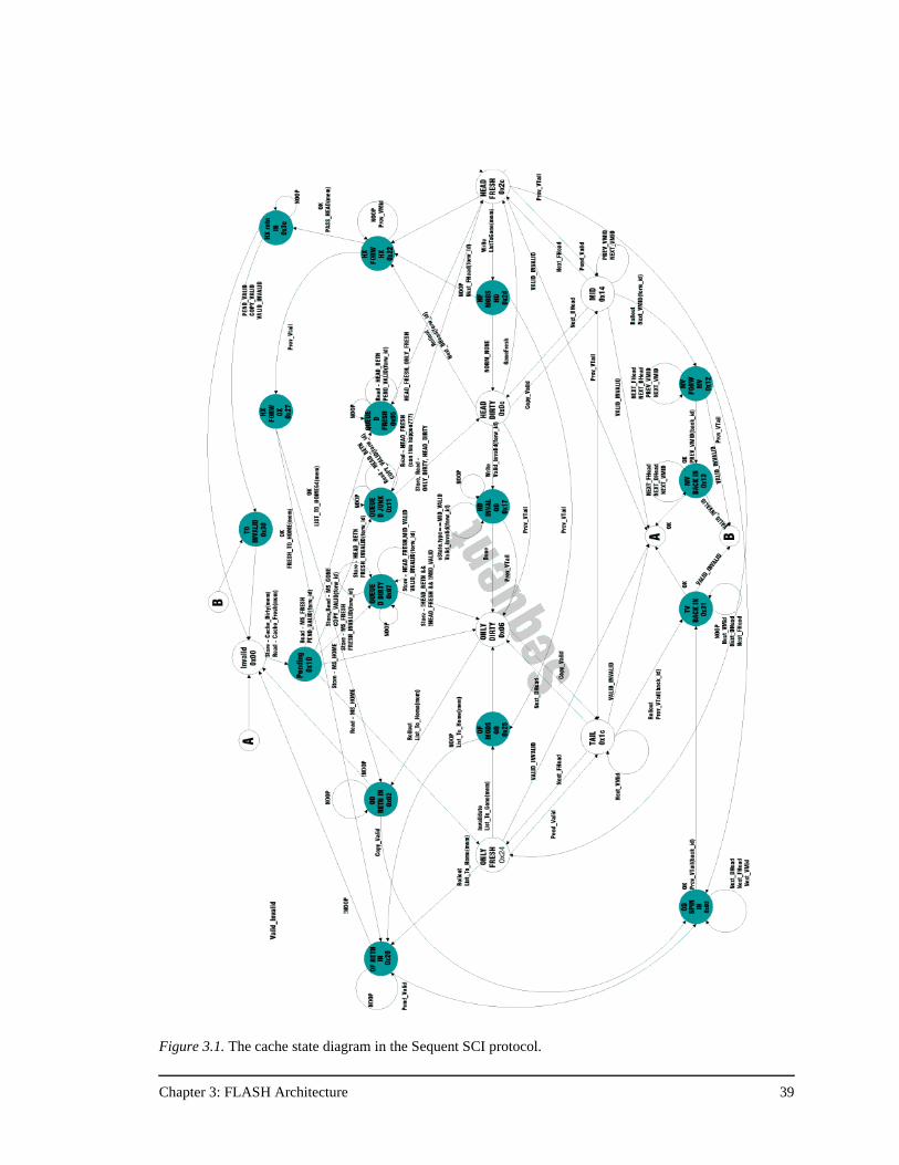
Chapter 3: FLASH Architecture 39
Figure 3.1. The cache state diagram in the Sequent SCI protocol.
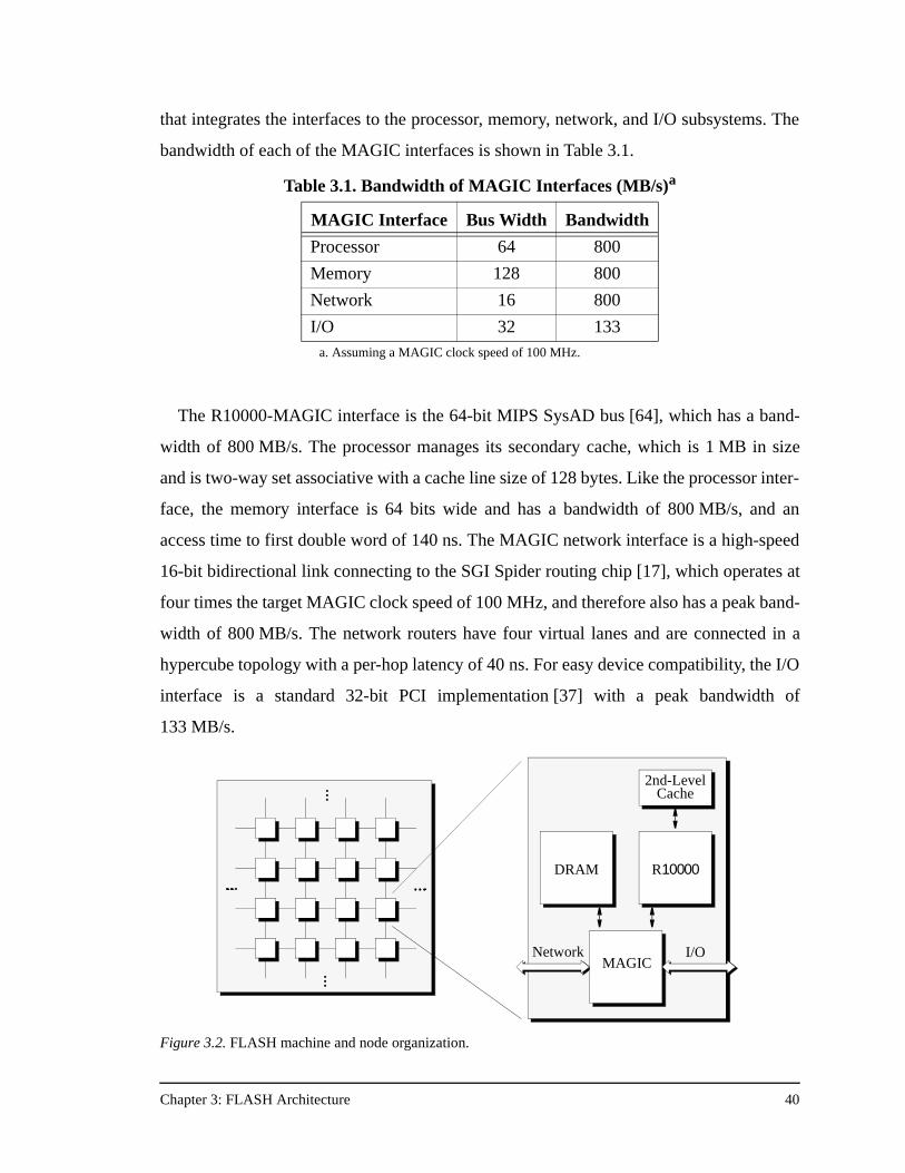
Chapter 3: FLASH Architecture 40
that integrates the interfaces to the processor, memory, network, and I/O subsystems. The
bandwidth of each of the MAGIC interfaces is shown in Table 3.1.
The R10000-MAGIC interface is the 64-bit MIPS SysAD bus [64], which has a band-
width of 800 MB/s. The processor manages its secondary cache, which is 1 MB in size
and is two-way set associative with a cache line size of 128 bytes. Like the processor inter-
face, the memory interface is 64 bits wide and has a bandwidth of 800 MB/s, and an
access time to first double word of 140 ns. The MAGIC network interface is a high-speed
16-bit bidirectional link connecting to the SGI Spider routing chip [17], which operates at
four times the target MAGIC clock speed of 100 MHz, and therefore also has a peak band-
width of 800 MB/s. The network routers have four virtual lanes and are connected in a
hypercube topology with a per-hop latency of 40 ns. For easy device compatibility, the I/O
interface is a standard 32-bit PCI implementation [37] with a peak bandwidth of
133 MB/s.
2$
I/ONetwork
2nd-LevelCache
2nd-LevelCache
DRAM µP
MAGIC
R10000DRAM
MAGIC
Figure 3.2. FLASH machine and node organization.
Table 3.1. Bandwidth of MAGIC Interfaces (MB/s)a
a. Assuming a MAGIC clock speed of 100 MHz.
MAGIC Interface Bus Width Bandwidth
Processor 64 800
Memory 128 800
Network 16 800
I/O 32 133
Chapter 3: FLASH Architecture 41
As the heart of the FLASH node, MAGIC is responsible for managing communication
both within and between FLASH nodes by running the appropriate communication proto-
col. Rather than hard-wiring a single communication protocol in hardware finite state
machines, MAGIC has a programmable core that runs software code sequences, or han-
dlers, to implement the communication protocols. This flexibility enables FLASH to run
multiple communication protocols, including all of the cache coherence protocols
described in Chapter 2, message passing protocols, and specialized synchronization proto-
cols. Flexibility also allows protocol designers to tune the protocol (or fix bugs!) even
after the machine has been implemented, and facilitates system performance monitoring.
Since all requests within the node must pass through MAGIC, the normal communication
protocol code sequences can be optionally augmented with performance monitoring infor-
mation such as counters and latency timers to track otherwise hard to monitor system per-
formance information [34].
As the node controller, MAGIC’s main job is essentially to act as a data crossbar, man-
aging the transfer of data between each of its four external interfaces. MAGIC’s central
location and its data crossbar functionality dictate that performance is a key design crite-
rion lest MAGIC itself become a bottleneck. One design alternative is to use a general-
purpose processor to implement the functions of the MAGIC chip. This would be an ideal
solution—let the complexity of the communication protocols be implemented in software
that runs on a commodity microprocessor acting as the node controller. The designers of
FLASH initially considered this option but discovered that it was too slow [29], especially
at moving long cache lines of data. At the other extreme, the “all-hardware” hard-wired
communication protocol approach was inflexible, and lacked the advantages of the more
flexible architecture. The key idea behind the design of MAGIC is an application of the
RISC philosophy: separate the data transfer logic from the control logic that implements
the communication protocols, and implement the data transfer logic in hardware to
achieve low-latency, high-bandwidth data transfers, and the control logic in a flexible,
programmable macro-pipeline to keep complex control decisions under software control.
Thus MAGIC is an exercise in hardware/software co-design, and the challenge lies in
meeting its strict performance goals.
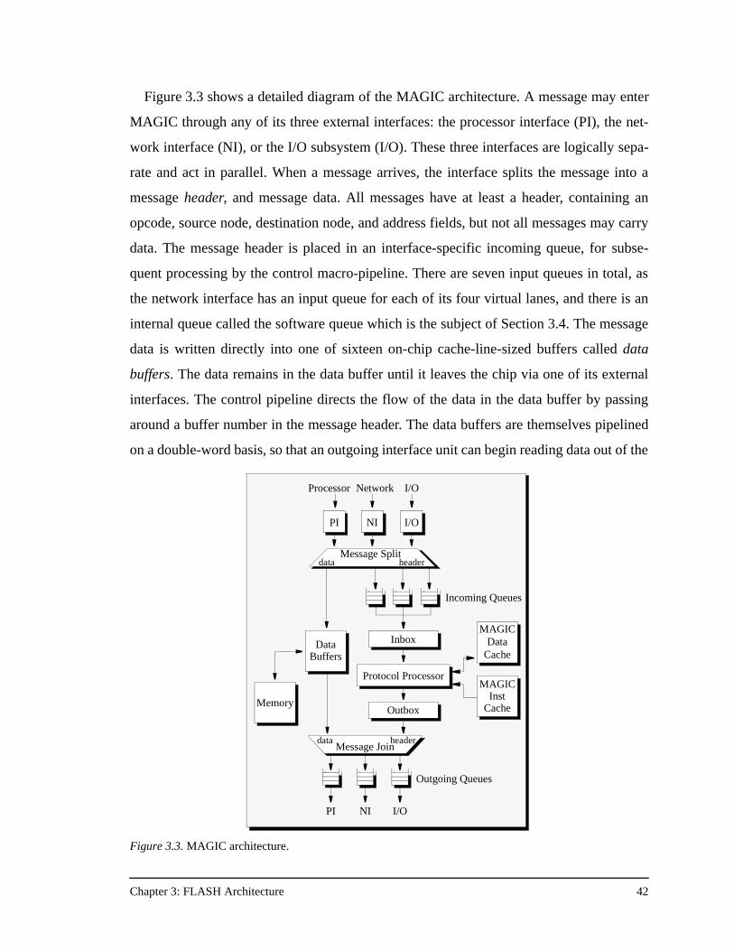
Chapter 3: FLASH Architecture 42
Figure 3.3 shows a detailed diagram of the MAGIC architecture. A message may enter
MAGIC through any of its three external interfaces: the processor interface (PI), the net-
work interface (NI), or the I/O subsystem (I/O). These three interfaces are logically sepa-
rate and act in parallel. When a message arrives, the interface splits the message into a
message header, and message data. All messages have at least a header, containing an
opcode, source node, destination node, and address fields, but not all messages may carry
data. The message header is placed in an interface-specific incoming queue, for subse-
quent processing by the control macro-pipeline. There are seven input queues in total, as
the network interface has an input queue for each of its four virtual lanes, and there is an
internal queue called the software queue which is the subject of Section 3.4. The message
data is written directly into one of sixteen on-chip cache-line-sized buffers called data
buffers. The data remains in the data buffer until it leaves the chip via one of its external
interfaces. The control pipeline directs the flow of the data in the data buffer by passing
around a buffer number in the message header. The data buffers are themselves pipelined
on a double-word basis, so that an outgoing interface unit can begin reading data out of the
Protocol Processor
InboxMAGIC
DataCache
PI
Processor Network I/O
PI NI I/O
PI NI I/O
Message Split
Protocol Processor
Inbox
MAGICInst
Cache
MAGICData
CacheData
Buffers
Incoming Queues
Outgoing Queues
data header
MemoryOutboxOutbox
Message Joindata header
Figure 3.3. MAGIC architecture.
Chapter 3: FLASH Architecture 43
buffer while an incoming interface is still filling the buffer. The lack of data copies and the
pipelined nature of the data buffers yield the desired low-latency, high bandwidth data
transfers mandated by MAGIC’s data crossbar functionality.
Once the external interface separates the message header from the message data, the
message header is ready to flow through MAGIC’s control macro-pipeline. The first stage
of the control macro-pipeline is the inbox. The inbox is responsible for selecting a mes-
sage header and associated address from one of the seven incoming queues, and generat-
ing a starting program counter (PC) for the protocol processor (PP), the next and most
important stage of the control pipeline. The PC is obtained by pushing the message header
through an associative hardware dispatch table called the jumptable. The matching jumpt-
able entry contains the starting PC for the protocol processor as well as a speculative
memory indication. The idea behind the speculative memory indication is that for com-
mon operations like a local cache fill, it is crucial to start the memory access as soon as
possible. Instead of waiting for the protocol processor to initiate the memory operation in
the software handler, the inbox can make that decision earlier in the macro-pipeline based
on the message opcode and thereby lower the overall request latency. After passing the
program counter and copies of the message header and address to the protocol processor,
the inbox can begin scheduling the next message.
The second stage in MAGIC’s control macro-pipeline is the protocol processor. The
protocol processor is a dual-issue statically-scheduled 64-bit RISC core. For implementa-
tion ease it does not support hardware interlocks, restartable exceptions, virtual memory
(it has no TLB), or floating point operations. The protocol processor implements 32 64-bit
physical registers, two complete integer units, one branch unit, one load/store unit, and
one shifter. The instruction set is MIPS-based [24], with additional support for efficient
bit-wise operations and special instructions to access state in MAGIC’s other internal
units. The bit-wise operations include bit-field insert and extract instructions as well as
branch-on-bit-set and branch-on-bit-clear instructions, all of which occur frequently in
typical protocol code sequences. To reduce memory bandwidth requirements, protocol
code is kept in an on-chip 16 KB MAGIC instruction cache, and protocol data structures
are kept in an off-chip 1 MB MAGIC data cache. Both caches are direct-mapped, have
line sizes of 128 bytes, and are backed by normal main memory. To handle the current
Chapter 3: FLASH Architecture 44
message, the protocol processor jumps to the program counter specified by the inbox and
begins executing the protocol handler at that location. The protocol handler is responsible
for updating protocol-specific state, and sending response messages if necessary. To send
a response, the protocol processor constructs a new message header and issues a send
instruction. The send instruction passes the header to the outbox which is responsible for
handling the mechanics of the message send. The protocol processor then issues a switch
instruction which blocks until the inbox hands it another message header, address, and
program counter.
The final stage of the three-stage macro-pipeline is the outbox, which receives send
instructions from the protocol processor and is responsible for placing the outgoing mes-
sage header in the appropriate external interface output queue, and possibly blocking if
that output queue is full. All three stages of MAGIC’s control macro-pipeline operate in
parallel, allowing up to three messages to be operated on concurrently. This parallelism
decreases the load on the protocol processor and improves the effective controller band-
width of MAGIC.
Once the message header has been placed in the outgoing queue of one of the external
interfaces, it eventually percolates to the head of the queue where the external interface re-
combines the message header with any associated message data by using the data buffer
specified in the message header, and sends the outgoing message out of MAGIC via its
external interface.
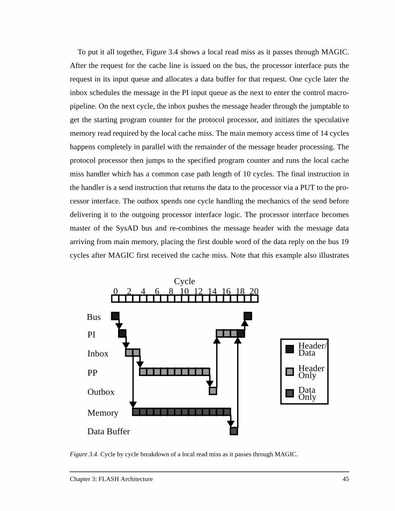
Chapter 3: FLASH Architecture 45
To put it all together, Figure 3.4 shows a local read miss as it passes through MAGIC.
After the request for the cache line is issued on the bus, the processor interface puts the
request in its input queue and allocates a data buffer for that request. One cycle later the
inbox schedules the message in the PI input queue as the next to enter the control macro-
pipeline. On the next cycle, the inbox pushes the message header through the jumptable to
get the starting program counter for the protocol processor, and initiates the speculative
memory read required by the local cache miss. The main memory access time of 14 cycles
happens completely in parallel with the remainder of the message header processing. The
protocol processor then jumps to the specified program counter and runs the local cache
miss handler which has a common case path length of 10 cycles. The final instruction in
the handler is a send instruction that returns the data to the processor via a PUT to the pro-
cessor interface. The outbox spends one cycle handling the mechanics of the send before
delivering it to the outgoing processor interface logic. The processor interface becomes
master of the SysAD bus and re-combines the message header with the message data
arriving from main memory, placing the first double word of the data reply on the bus 19
cycles after MAGIC first received the cache miss. Note that this example also illustrates
0 2 4 6 8 10 12 14 16 18
Bus
PI
Inbox
PP
Outbox
Memory
Data Buffer
20Cycle
Header/Data
HeaderOnly
DataOnly
Figure 3.4. Cycle by cycle breakdown of a local read miss as it passes through MAGIC.
Chapter 3: FLASH Architecture 46
the use of data buffer pipelining, as the PI is reading data out of the beginning of the data
buffer while the memory system is still filling the latter part of the same buffer.
This section provides a high-level description of the path of a message as it travels
through MAGIC. The detailed workings of the MAGIC chip are beyond the scope of this
paper (a complete description can be found in [29]), but there are some details relevant to
the implementation of communication protocols in general and cache coherence protocols
in particular, which are important to the understanding of how cache coherence protocols
run on MAGIC and how they can run in a deadlock-free manner. The next section dis-
cusses several such detailed implementation issues.
3.3 MAGIC Subsystem Protocol Support
Many of MAGIC’s internal units have features that facilitate the execution of deadlock-
free communication protocols, or have internal state that the communication protocol
needs to manage as part of the global system state. This section details these unit charac-
teristics working from the external interfaces of MAGIC inward to the protocol processor
itself.
3.3.1 Processor Interface
The processor interface is MAGIC’s interface to the SysAD bus of the R10000. The
processor interface must manage processor-to-MAGIC requests such as cache read and
write misses, writebacks, and replacement hints, as well as MAGIC-to-processor transac-
tions. The MAGIC-to-processor commands fall into two categories: replies to processor
requests for cache lines, and interventions. Interventions are unsolicited commands sent
from MAGIC to the processor and include invalidations, which simply mark a line invalid
in the cache if present, GET interventions, which retrieve the cache line from the cache if
present and leave the line in the SHARED state, and GETX interventions, which retrieve
the cache line from the cache and leave it in an INVALID state. Table 3.2 lists the major
processor-to-MAGIC and MAGIC-to-processor commands.
Absent from the list of supported interventions on FLASH is the ability to update a
cache line in the processor’s secondary cache. Recall from Chapter 2 that there are two
main classes of cache coherence protocols, invalidation-based protocols and update-based
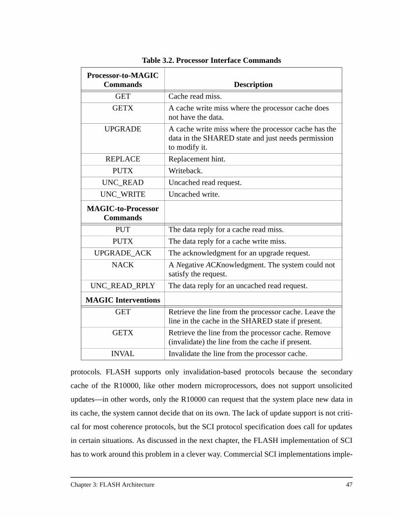
Chapter 3: FLASH Architecture 47
protocols. FLASH supports only invalidation-based protocols because the secondary
cache of the R10000, like other modern microprocessors, does not support unsolicited
updates—in other words, only the R10000 can request that the system place new data in
its cache, the system cannot decide that on its own. The lack of update support is not criti-
cal for most coherence protocols, but the SCI protocol specification does call for updates
in certain situations. As discussed in the next chapter, the FLASH implementation of SCI
has to work around this problem in a clever way. Commercial SCI implementations imple-
Table 3.2. Processor Interface Commands
Processor-to-MAGIC Commands Description
GET Cache read miss.
GETX A cache write miss where the processor cache does not have the data.
UPGRADE A cache write miss where the processor cache has the data in the SHARED state and just needs permission to modify it.
REPLACE Replacement hint.
PUTX Writeback.
UNC_READ Uncached read request.
UNC_WRITE Uncached write.
MAGIC-to-Processor Commands
PUT The data reply for a cache read miss.
PUTX The data reply for a cache write miss.
UPGRADE_ACK The acknowledgment for an upgrade request.
NACK A Negative ACKnowledgment. The system could not satisfy the request.
UNC_READ_RPLY The data reply for an uncached read request.
MAGIC Interventions
GET Retrieve the line from the processor cache. Leave the line in the cache in the SHARED state if present.
GETX Retrieve the line from the processor cache. Remove (invalidate) the line from the cache if present.
INVAL Invalidate the line from the processor cache.
Chapter 3: FLASH Architecture 48
ment a third-level cluster cache under system control, and have the ability to update the
cluster cache, but not the main processor cache.
Because the PI supports bi-directional communication between MAGIC and the
R10000 it is easy to imagine race conditions. For example, what happens if an invalidation
request arrives for a cache line which currently has an outstanding read miss? These kinds
of decisions should ideally be under protocol control, as different protocols may wish to
perform different actions. To maintain this flexibility, the PI has two separate internal data
structures: the Outstanding Transaction Table (OTT) and the Conflict Resolution Table
(CRT). The OTT contains any currently outstanding transactions from the main processor,
of which there can be a maximum of four. Any time an intervention request arrives at the
processor interface, it searches the OTT to check for the presence of the same address. If it
is present, the PI consults the programmable CRT which outputs an appropriate action.
This programmability has proved useful. Consider the case where an invalidation inter-
vention arrives for a line which has a currently outstanding read request in the OTT. The
CRT marks that an invalidation request has occurred and processes the invalidation nor-
mally. The question is what happens when the PUT reply shows up for the outstanding
GET? The answer is protocol-specific. The CRT shows that a PUT has arrived for a previ-
ous GET and that the line has also been invalidated in the interim. Under the bit-vector
protocol it cannot be guaranteed that the data in the PUT reply is safe to use, so the CRT is
programmed to output a NACK reply that is forwarded on to the processor. The NACK
reply indicates that the processor needs to retry the request if it still wants the cache line.
But under the SCI protocol a PUT arriving in this situation always has data that is safe to
use, so the CRT entry for this case is programmed to allow the PUT to be forwarded to the
processor, satisfying the cache miss. Sprinkling this type of flexibility throughout the
MAGIC chip makes things easier for a protocol designer and increases the likelihood that
MAGIC can run any kind of coherence protocol, even those with unforeseen message
interactions, such as SCI.
Another processor interface feature for protocol support is the fence count register. The
fence count register is the key to supporting relaxed memory consistency models in
FLASH. The R10000 has the ability to perform a memory barrier, or fence, operation in
the form of a sync instruction. A sync from the R10000 ensures that all previous requests
Chapter 3: FLASH Architecture 49
have been completed. From the R10000 point of view this means it needs to make sure
that all of its internal queues are empty so that the system has seen all previous processor
requests. It then checks an external pin controlled by MAGIC called GloballyPerformed.
On a sync instruction, the R10000 stalls until the GloballyPerformed pin is asserted.
MAGIC asserts this pin only when the fence count register in the PI is zero. Any time the
processor interface receives a read miss or a write miss from the R10000 it increments the
fence count register. Read replies sent back to the processor decrement the fence count
register. Write replies may or may not decrement the register depending on the memory
consistency model currently being supported. Only when all invalidation acknowledg-
ments have been collected on behalf of a particular write miss should the fence count be
decremented for that miss. If the coherence protocol is running under a weak consistency
model, the write-miss data reply will not decrement the fence count register. Instead, the
write-miss data reply is sent to the processor immediately, and a separate message is sent
to the PI to decrement the fence count register when all invalidation acknowledgments
have been collected. Because of the way in which the data reply and the fence count decre-
ment are de-coupled, weak consistency models require the processor to issue a sync
instruction any time it wants to ensure that all of its previous writes are visible to the rest
of the system.
Finally, the processor interface has several features to support error detection, fault
recovery, and deadlock avoidance which are exported to the protocol level. To help detect
invalid memory references by the R10000, the PI is programmed to know the amount of
main memory on the local node. Any attempt to access a local memory address above this
value will cause the PI to set an OutOfRange bit. When the inbox schedules the message,
it passes the OutOfRange bit through the JumpTable and therefore has the capability of
calling a different handler based on whether the OutOfRange bit is set or not. In practice
the OutOfRange bit can be used to protect high regions of memory from access by the pro-
cessor, acting as a firewall—even from the operating system! FLASH uses this trick to
protect sensitive protocol code and data from being overwritten by the main processor.
The PI also detects parity errors on the SysAD bus, and the inbox will dispatch a special
ErrorPC if the PI indicates a SysAD parity error. To aid fault recovery, the inbox runs a
special handler called the IdleHandler at a programmable interval that is responsible for
Chapter 3: FLASH Architecture 50
making sure MAGIC is still functioning properly. One of its duties is to check timer values
associated with each entry in the PI’s Outstanding Transaction Table. If the IdleHandler
determines that the timer values have exceeded some time-out value, it can drop the sys-
tem into fault recovery. An OTT time-out would indicate either a cache coherence proto-
col bug, or a serious hardware error somewhere in the system.
3.3.2 Network Interface
The network interface connects MAGIC to the SGI Spider routing chips. The network
implements four virtual lanes on top of one physical link. The cache coherence protocols
use these virtual lanes to implement logically separate request and reply networks. Lane 0
is the request network and lane 1 is the reply network. The remaining two lanes are used
for fault recovery and performance monitoring purposes. Using virtual lanes to implement
separate request and reply networks is the first step toward deadlock-free cache coherence
protocols. However, the mere existence of logically separate networks is not sufficient to
guarantee that the machine will not deadlock. The logically separate networks break any
request/reply cycles. As described next, other steps need to be taken to break reply/reply
cycles and request/request cycles.
Reply/reply cycles are broken simply by requiring that any cache coherence protocol
must sink all replies. In other words, the handler for a reply message must not generate
any additional messages (either requests or replies). But even with this requirement, proto-
cols still need some hardware support from MAGIC to ensure that all replies are sunk.
Recall that all incoming messages allocate one of MAGIC’s sixteen data buffers. Each
message in MAGIC’s input queues consumes one data buffer, and messages with data in
MAGIC’s output queues also consume a data buffer. It is possible that an arriving message
is ready to be pulled off the network reply lane, but MAGIC doesn’t have a data buffer
available and thus is unable to accept the message. This breaks the rule that MAGIC
should always be able to sink replies. It is not guaranteed that a data buffer will become
free eventually, because MAGIC may have to send a message from its output queue to
guarantee this, but it is not guaranteed to be able to do that because the network could be
backed up by other nodes in the same predicament as this MAGIC chip. To solve this
problem, MAGIC implements the notion of reserved data buffers. Each network virtual
Chapter 3: FLASH Architecture 51
lane may have a reserved data buffer that only it can allocate. This means that the reply
lane can always eventually pull an arriving reply message off the network by using its
reserved data buffer. This is qualified with “eventually” because at any point in time the
NI may have just used its reserved buffer for this purpose and thus it is not available. But
since this reply message is guaranteed not to send any additional messages, the data buffer
will become free as soon as the protocol processor handles the message. At that point, the
NI can re-use the reply lane reserved data buffer. Request/request cycles are broken, in
part, by the existence of a reserved buffer for the request lane as well. However, in the case
of request/request cycles more hardware support is required, and that is discussed in the
Inbox and Protocol Processor sections.
Like the processor interface, the network interface has support for error detection and
fault recovery. All network packets are protected by a cyclic redundancy check (CRC)
code. If the CRC check fails, the network interface sets an error indication, just as the pro-
cessor interface marks an error when it detects bad SysAD bus parity. The inbox will dis-
patch the ErrorPC in response to a network header CRC error. To aid in fault containment
and recovery, the network interface also calculates a worker bit that determines whether
the source node of the message lies in the same partition, or cell, as the current node. Once
again the inbox has the ability to dispatch a different handler based on the value of the
worker bit. Certain cell-based operating systems [42] can use this ability to implement
firewalls on write operations to limit the ability of programs running in one cell to corrupt
critical portions of main memory in another cell.
3.3.3 I/O Interface
The I/O interface connects MAGIC to an industry-standard 32-bit PCI bus. MAGIC
acts as the PCI master. All messages received from the PCI bus are placed in a single input
queue read by the inbox. Incoming messages are either DMA read or write requests or
interrupts coming from one of the devices attached to the PCI bus. All DMA requests
fetch an entire cache line (128 bytes) of data and return it to a single entry on-chip
MAGIC I/O cache. The I/O cache is really just one of MAGIC’s on-chip data buffers, with
the actual buffer number dynamically allocated from the pool of free buffers.
Chapter 3: FLASH Architecture 52
From the protocol’s perspective, the I/O system acts just like any processor in the sys-
tem: it is capable of asking for, and caching, any cache line in the system. Normally this
would mean that any protocol data structure that reflects the “machine size” would need to
expand to accommodate twice as many nodes because now there is 1 additional I/O inter-
face per processor. To avoid this problem, the I/O interface takes the simplifying action of
only requesting lines exclusively. That is, any line in the I/O cache has been fetched such
that no other cache (processor, or I/O) in the system may continue to hold that cache line.
This allows FLASH protocols to implement support for cache-coherent I/O by simply
adding an I/O bit to the protocol data structure, and setting that bit as well as the existing
owner field to the node number of the I/O system that requests the cache line.
The existence of the I/O bit does complicate some protocol cases. Normally if a cache
line is dirty somewhere in the system, and another processor requests that line, the proto-
col will notice that the line is dirty and retrieve it from the processor on the node indicated
in the owner field. However, with cache-coherent I/O the cache line may be either in the
processor cache or the I/O cache, depending on the value of the I/O bit. So the protocol
must check an additional bit, and send the appropriate message type (GET from I/O or a
normal GET).
3.3.4 Inbox
Recall that the main function of the inbox is to schedule MAGIC’s seven input queues.
Communication protocols impose some requirements on scheduling to ensure that dead-
lock-free protocols can be implemented on FLASH.
The first requirement is fairness. The inbox must ensure that at the hardware level, the
scheduling algorithm is fair and does not lead to starvation of any of the seven message
sources. The inbox meets this requirement by implementing a round robin scheduling
algorithm. The current highest priority queue is the queue immediately “after” the queue
last scheduled, as shown in Equation 3.1.
(3.1)Highest Priority Queue Number = Last Scheduled Queue Number 1+( ) modulo 7
Chapter 3: FLASH Architecture 53
While the fairness requirement is fairly basic, a much more interesting question is under
what conditions can the inbox schedule an incoming queue. Can the inbox schedule an
input queue as soon as the queue has a message available? The answer is maybe. The
inbox must also ensure that certain network output queue space requirements are met. Cer-
tain input queues may need to have a certain amount of guaranteed space available in one
of the four MAGIC network output queues to ensure that the machine will not deadlock.
For example the network request input queue requires space in the network reply output
queue because most requests need to send replies. If the inbox scheduled an incoming
request without space in the outgoing reply queue and the protocol handler needed to send
a reply, it would be stuck. The protocol processor could not just wait for outgoing reply
queue space to free up because the only way it is guaranteed to do so is if this MAGIC
keeps draining incoming replies from the network. Of course, MAGIC cannot drain
incoming replies from the network if the protocol processor is blocked, waiting for outgo-
ing queue space.
The inbox solves this problem by preventing it from arising. Each of the seven interface
input queues has a programmable 4-bit vector associated with it that indicates whether it
requires space in the corresponding network output queue before it can be scheduled.
Table 3.3 shows how the bit-vector for each of the input queues is programmed for all
FLASH coherence protocols to date. Note that the NI request queue requires outgoing
reply queue space (lane 1) before it can be scheduled, avoiding the scenario outlined
above. Note also that the reply queue does not have any outgoing queue space require-
ments. This is a corollary to the rule that MAGIC must drain all incoming replies—
MAGIC must always be able to schedule incoming replies regardless of the state of its
output queues. If the bit-vector indicates outgoing queue space is required, the inbox actu-
ally guarantees that two slots are free before it schedules the message. This was a design
decision made to ease the job of the protocol programmer, since many coherence protocols
that include a common optimization called forwarding have incoming requests that need
to send two replies.
Finally, the inbox performs a critical address comparison function that allows the
MAGIC architecture’s control macro-pipeline to safely operate on up to three separate
messages simultaneously. Because of the pipelined structure of the inbox and the protocol

Chapter 3: FLASH Architecture 54
processor, and the fact that both can initiate memory operations, there is a potential race
condition between the two units. If both units are operating on two separate requests to the
same cache line, then it is possible that the inbox may initiate a speculative read operation
and that the protocol processor may initiate a memory write operation. In the absence of
any special hardware, the read initiated by the inbox may return the value of the cache line
before the protocol processor’s write, or it may return the value after the protocol proces-
sor’s write depending on the timing of the two requests. Because the control macro-pipe-
line is only an implementation optimization, its existence should never be visible to the
protocol designer. In other words, any memory read by the inbox needs to return the value
written by the protocol processor if such a case arises. To handle this case, the inbox per-
forms a cache line-aligned address comparison with its current address and its previous
address (the one now in the protocol processor). If the two cache lines are the same, the
inbox delays any speculative memory operations until the previous handler completes.
This guarantees that the inbox will read any data written to that address by the protocol
processor in that handler.
There are times however, where this address comparison is insufficient. The address
comparison works if the protocol processor writes only the address contained in the mes-
sage header. While this is true of all the cache coherence protocols discussed in this paper,
there are other protocols, including some message passing protocols designed for FLASH,
where the protocol processor writes to addresses not passed around in the message header,
and therefore the race condition between the inbox and the protocol processor persists.
The inbox solves the problem completely by including a wait bit in the jumptable. Each
handler has a wait bit associated with it that is set if that handler is one in which the proto-
Table 3.3. Output Queue Space Scheduling Requirements
Input QueueScheduling Vector
(lane 0, lane 1, lane 2, lane3)
PI (1, 0, 0, 0)
NI request (0, 1, 0, 0)
NI reply (0, 0, 0, 0)
I/O (1, 0, 0, 0)
Software Queue (1, 1, 0, 0)
Chapter 3: FLASH Architecture 55
col processor may write to addresses not contained within the message header. It is up to
the protocol designer to ensure that the jumptable is programmed with the proper wait bit
information. If the inbox ever dispatches a handler with the wait bit set, the inbox will
delay any speculative memory operations for the next message it handles until the proto-
col processor has finished executing the handler with the wait bit set. In effect the wait bit
indication is logically ORed with the results of the address comparison to determine
whether the inbox delays speculative memory operations to avoid the possible race condi-
tion caused by the presence of the control macro-pipeline.
3.3.5 Protocol Processor
The protocol processor runs the software handler that processes the current message,
and therefore naturally plays a key role in both the correctness of the coherence protocol
and the deadlock avoidance strategy of the FLASH machine. While the external interface
units and the inbox provide much of the hardware support needed to correctly run a coher-
ence protocol, there are still a few things left to the protocol processor, and a few guide-
lines the protocol designer has to follow when writing code for the protocol processor.
The first requirement is that the protocol processor cannot block, nor can it poll, waiting
for space to free in any of the external interface output queues. As previously discussed
this can trivially lead to deadlock of the entire machine. This rule has different conse-
quences depending on which output queue is in question. For both the processor interface
and I/O output queues this means that the processor and I/O system must be capable of
draining those queues without requiring further help from MAGIC. In other words, a pro-
tocol processor send to a full PI or I/O output queue is allowed to happen and temporarily
stalls the protocol processor. But because these queues must drain on their own, the proto-
col processor is guaranteed to be able to eventually complete the send.
The network output queues are treated differently. The protocol processor cannot send
to a full NI output queue. In most cases this is not an issue because the inbox guarantees
output reply queue space for incoming requests, and incoming replies do not send any out-
going messages. But, unfortunately, there are times when incoming requests need to send
one or more outgoing requests. The inbox cannot and does not require outgoing request
queue space for incoming requests because that would lead to deadlock. Instead, any
Chapter 3: FLASH Architecture 56
incoming request that wants to send outgoing requests must check for space in the output
request queue within the handler. The protocol processor provides special load state and
store state instructions that allow it to access state in MAGIC’s other internal units. This is
how the protocol processor decrements the aforementioned fence count register in the PI,
and it is also how it reads the amount of space remaining in the network output request
queue. Since the inbox may be reserving output request queue space for some other han-
dler that it has already scheduled, the protocol processor conservatively assumes that the
amount of outgoing request queue space that it can use is the amount actually available
minus the two slots potentially reserved by the inbox. If the handler determines that there
is enough available output request queue space then it is safe to send the outgoing request
and the handler is allowed to proceed. If the handler detects insufficient outgoing queue
space it must negatively acknowledge (NACK) the request. Since a NACK is a reply, and
outgoing reply queue space is guaranteed by the inbox for all incoming requests, it is
always safe to NACK an incoming request and convert it into a reply. The combination of
inbox scheduling guarantees, handler output queue space checking, and NACKs solve
almost all the deadlock avoidance problems encountered by cache coherence protocols.
Unfortunately, “almost” is not good enough. There is one more important case that
deserves some special consideration since the previously proposed solutions are not suffi-
cient to provide a deadlock-free environment for cache coherence protocols. Consider a
write to a cache line which is widely shared throughout the machine. The write request
requires the protocol processor to send an invalidation to every processor which caches
the line. Since the write miss is an incoming request, and invalidations are outgoing
requests, the protocol processor is required to check for enough queue space to send inval-
idations. Since MAGIC’s NI output request queue is only sixteen entries deep, it is easy to
imagine situations where the protocol processor needs to send more invalidations than it
has available queue space to send. The handler does its best to maximize the number it can
send by reading the initial number of queue spaces available, sending that many invalida-
tions, and then reading the number of queue spaces available again. This process repeats,
and is often sufficient to allow all invalidations to be sent and the handler to complete suc-
cessfully. But this is not necessarily always the case. If the protocol processor reads insuf-
ficient queue space and it still has invalidations to send, what does it do? It cannot simply
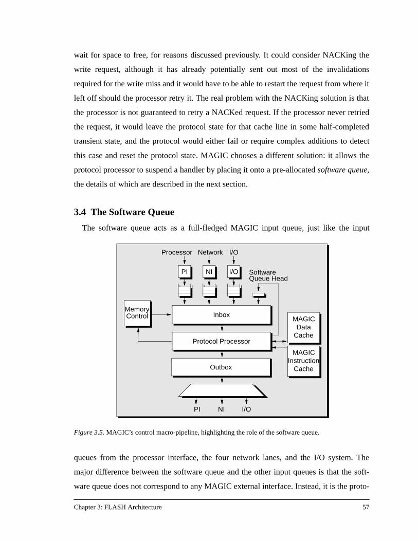
Chapter 3: FLASH Architecture 57
wait for space to free, for reasons discussed previously. It could consider NACKing the
write request, although it has already potentially sent out most of the invalidations
required for the write miss and it would have to be able to restart the request from where it
left off should the processor retry it. The real problem with the NACKing solution is that
the processor is not guaranteed to retry a NACKed request. If the processor never retried
the request, it would leave the protocol state for that cache line in some half-completed
transient state, and the protocol would either fail or require complex additions to detect
this case and reset the protocol state. MAGIC chooses a different solution: it allows the
protocol processor to suspend a handler by placing it onto a pre-allocated software queue,
the details of which are described in the next section.
3.4 The Software Queue
The software queue acts as a full-fledged MAGIC input queue, just like the input
queues from the processor interface, the four network lanes, and the I/O system. The
major difference between the software queue and the other input queues is that the soft-
ware queue does not correspond to any MAGIC external interface. Instead, it is the proto-
DP
Inbox
Outbox
MemoryControl
PI NI I/O
Protocol Processor
Processor Network I/O
PI NI I/O SoftwareQueue Head
Inbox
Outbox
PI NI I/O
MemoryControl
MAGICInstruction
Cache
MAGICInstruction
Cache
MAGICInstruction
Cache
MAGICData
Cache
Figure 3.5. MAGIC’s control macro-pipeline, highlighting the role of the software queue.
Chapter 3: FLASH Architecture 58
col processor itself which places messages onto the software queue. The software queue is
simply a reserved region of main memory where the protocol processor can suspend han-
dlers so that they run at some later time. The first element of the software queue is kept in
hardware in the inbox so that it can participate in the hardware scheduling among all seven
input queues (see Figure 3.5). Any time the software queue is scheduled, the handler is
responsible for moving the next element of the queue from main memory (cacheable by
the MAGIC data cache) into the inbox software queue head registers.
The software queue provides the last piece of the FLASH deadlock avoidance solution.
Any time a request has the capability of sending out more than one outgoing network
request, the handler must reserve a space in the software queue by incrementing the soft-
ware queue count register, usually kept in a global protocol processor register by the
coherence protocol. If there is no space because the software queue is full, the incoming
request is immediately NACKed. In practice this case can be completely avoided by sizing
the software queue appropriately (64 to 128 entries). Once the handler reserves software
queue space it proceeds with handler execution as normal.
The classic use of the software queue is exemplified by continuing the earlier invalida-
tion example. When the handler needs to send more invalidation requests out the network
and there is no more outgoing request queue space, the protocol processor simply places
the current request on the software queue. At some later time, perhaps even the next han-
dler, the protocol processor will pick up where it left off. Using the software queue does
not cause any race conditions in the protocol because the directory is kept in a pending
state which causes any other requests for that cache line to be immediately NAKed. Only
the software queue handler can make forward progress on the state of the suspended cache
line. Once all invalidations have been sent, the software queue handler terminates nor-
mally without rescheduling itself. When the protocol receives all the invalidation
acknowledgments, the software queue count register is decremented, freeing the space the
original write request had reserved in the software queue.
All FLASH protocols, including message passing and specialized synchronization pro-
tocols use the software queue as a critical weapon in their deadlock avoidance strategy. It
is not only used to break request/request cycles as above, but it is also used to break
reply/reply cycles in protocols like SCI where despite the golden rule, incoming replies
Chapter 3: FLASH Architecture 59
sometimes send additional messages. The Alewife machine from MIT proposed a similar
software queue idea to solve the deadlock problem, but in their implementation once one
message was placed on the software queue, all messages had to go to the software queue
because of ordering concerns. This presented a possible “machine slowdown” scenario
where once the controller started to schedule from the software queue it could never get
itself out of that state. The MAGIC software queue provides a highly flexible solution to
the deadlock avoidance problem without handicapping the rest of the machine.
3.5 Programming MAGIC
The previous sections detailed MAGIC hardware support for running communication
protocols. Although MAGIC hardware performs the useful tasks of handling the data
movement and implementing part of the deadlock avoidance strategy, the bulk of the work
still falls on the protocol designer in writing the protocol handlers for the protocol proces-
sor. The protocol code is still responsible for knowing the outgoing message send require-
ments, checking outgoing queue space when necessary, freeing data buffers, and
managing the software queue in addition to simply running the code that implements the
underlying protocol.
Worse yet, any mistake in managing these machine resources can easily lead to dead-
lock of the entire machine. Combined with the complexity of the protocols themselves, it
is easy to see that writing protocols is a difficult task and it is easy to get wrong. This
argues for flexibility and programmability in the protocol implementation, and that is the
main tenet of the MAGIC design philosophy.
The flexibility and programmability of MAGIC allows each of the four coherence pro-
tocols discussed in Chapter 2 to be implemented on FLASH, and ultimately leads the way
to a performance comparison of four drastically different protocols running on top of the
same multiprocessor architecture. The next chapter details the implementation of each of
these protocols on the FLASH machine in route to a quantitative analysis of their perfor-
mance, scalability, and robustness.
Chapter 4: FLASH Protocol Implementations 60
Chapter 4
FLASH Protocol Implementations
To fully understand the results of comparing the performance and scalability of DSM
cache coherence protocols using the FLASH multiprocessor as the experimental test-bed,
it is first necessary to describe the specific FLASH implementation of the four protocols
described in Chapter 2. Although Chapter 2 discusses the high-level data structures, mem-
ory overhead, and common transactions of each protocol, it does not present enough infor-
mation to understand the direct protocol overhead of each protocol as it is implemented on
FLASH.
This chapter discusses the particulars of the FLASH implementation of the bit-vec-
tor/coarse-vector, dynamic pointer allocation, SCI, and COMA cache coherence proto-
cols. Section 4.1 first details the FLASH protocol development environment, showing
how protocols are written and what tools are used in the process. With a clear picture of
this environment in mind, each protocol is described in detail, including the layout and
meaning of low-level data structures, global register usage, network message type and
lane encodings, and any unique protocol-specific requirements or special deadlock avoid-
ance concerns. Examples of common protocol sequences for each protocol are given in
Appendix A. From this chapter the reader will gain a thorough understanding of each pro-
tocol implementation, and will then be ready for the comparison of performance, scalabil-
ity and robustness of the protocols in Chapter 6.
4.1 FLASH Protocol Development Environment
Every cache coherence protocol developed for FLASH is written in C. The first step in
writing a new protocol is deciding what protocol data structures to use to store the direc-
tory and any other auxiliary information the protocol needs to maintain. These data struc-
tures are simply declared as C struct statements. The main purpose of the next four
sections is to describe these C structures and their fields for each of the four cache coher-
ence protocols.
Chapter 4: FLASH Protocol Implementations 61
After declaring the data structures for a protocol, the designer must declare the message
types that the protocol sends, and declare each type of message as either a request or a
reply. The choice of message type determines the lane the message will use in the FLASH
network, which has four virtual lanes. The lane used by a message has protocol implica-
tions, since point-to-point order is guaranteed between two nodes only if messages are
sent on the same virtual lane. A protocol can take advantage of this per-lane message
ordering to reduce its number of race conditions and transient states.
Once the protocol data structures and message types are well defined, the final step of
FLASH protocol development is to write the protocol handlers. The protocol handlers are
the code that the protocol processor executes when the inbox dispatches a new incoming
message. The number of protocol handlers varies between protocols, depending both on
the number of message types in the protocol and the number of other dispatch conditions
specified by the jumptable in the inbox. The jumptable can dispatch different handlers
based not only on the message type, but also based on the external interface from which
the message arrived (PI, NI, I/O), whether the address in the message is local or remote,
and a host of other conditions contained in the incoming message’s header and address, as
shown in Table 4.1. Each protocol handler must have an associated jumptable entry speci-
fying the starting program counter (PC) value of the handler as well as whether a specula-
tive memory operation should be initiated, and if so, what type of operation.
The starting PC in the jumptable is actually specified by the handler name, which is
converted into a numerical PC value during the protocol compilation phase. The handler
names for all the FLASH protocols are the concatenation of the incoming interface, the
local/remote indication, and the message type. For example, a local cache read miss trig-
gers the PILocalGet handler since the incoming MAGIC interface is the PI, the
local/remote indication is local, and the message type is GET. A remote write miss satis-
fied by the home triggers a sequence of three handlers: PIRemoteGetX at the requester,
NILocalGetX at the home, and NIRemotePutX for the response back at the requester.
Some handler names append other information, for example NILocalGetX has two
variants depending on the consistency mode—NILocalGetXEager for EAGER mode
and NILocalGetXDelayed for DELAYED mode. Examples of some common han-
dlers are shown in the individual protocol sections that follow.
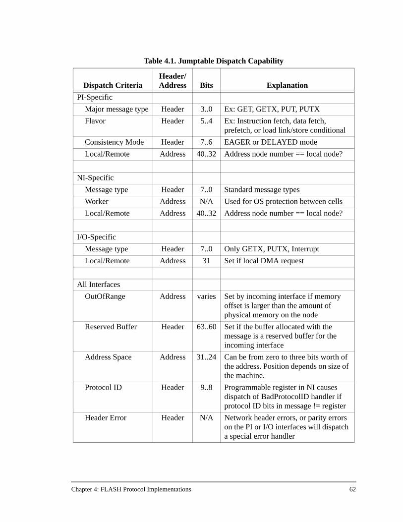
Chapter 4: FLASH Protocol Implementations 62
Table 4.1. Jumptable Dispatch Capability
Dispatch CriteriaHeader/Address Bits Explanation
PI-Specific
Major message type Header 3..0 Ex: GET, GETX, PUT, PUTX
Flavor Header 5..4 Ex: Instruction fetch, data fetch, prefetch, or load link/store conditional
Consistency Mode Header 7..6 EAGER or DELAYED mode
Local/Remote Address 40..32 Address node number == local node?
NI-Specific
Message type Header 7..0 Standard message types
Worker Address N/A Used for OS protection between cells
Local/Remote Address 40..32 Address node number == local node?
I/O-Specific
Message type Header 7..0 Only GETX, PUTX, Interrupt
Local/Remote Address 31 Set if local DMA request
All Interfaces
OutOfRange Address varies Set by incoming interface if memory offset is larger than the amount of physical memory on the node
Reserved Buffer Header 63..60 Set if the buffer allocated with the message is a reserved buffer for the incoming interface
Address Space Address 31..24 Can be from zero to three bits worth of the address. Position depends on size of the machine.
Protocol ID Header 9..8 Programmable register in NI causes dispatch of BadProtocolID handler if protocol ID bits in message != register
Header Error Header N/A Network header errors, or parity errors on the PI or I/O interfaces will dispatch a special error handler
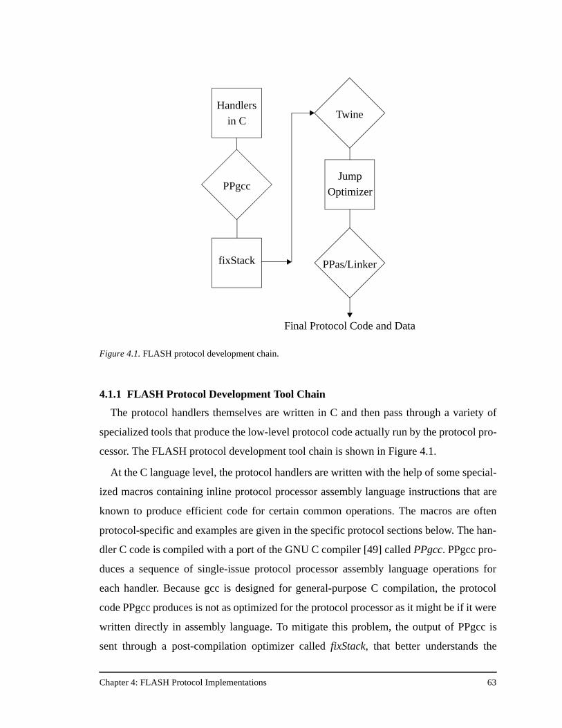
Chapter 4: FLASH Protocol Implementations 63
4.1.1 FLASH Protocol Development Tool Chain
The protocol handlers themselves are written in C and then pass through a variety of
specialized tools that produce the low-level protocol code actually run by the protocol pro-
cessor. The FLASH protocol development tool chain is shown in Figure 4.1.
At the C language level, the protocol handlers are written with the help of some special-
ized macros containing inline protocol processor assembly language instructions that are
known to produce efficient code for certain common operations. The macros are often
protocol-specific and examples are given in the specific protocol sections below. The han-
dler C code is compiled with a port of the GNU C compiler [49] called PPgcc. PPgcc pro-
duces a sequence of single-issue protocol processor assembly language operations for
each handler. Because gcc is designed for general-purpose C compilation, the protocol
code PPgcc produces is not as optimized for the protocol processor as it might be if it were
written directly in assembly language. To mitigate this problem, the output of PPgcc is
sent through a post-compilation optimizer called fixStack, that better understands the
Figure 4.1. FLASH protocol development chain.
Handlers
in C
PPgcc
fixStack
Twine
Jump
Optimizer
PPas/Linker
Final Protocol Code and Data
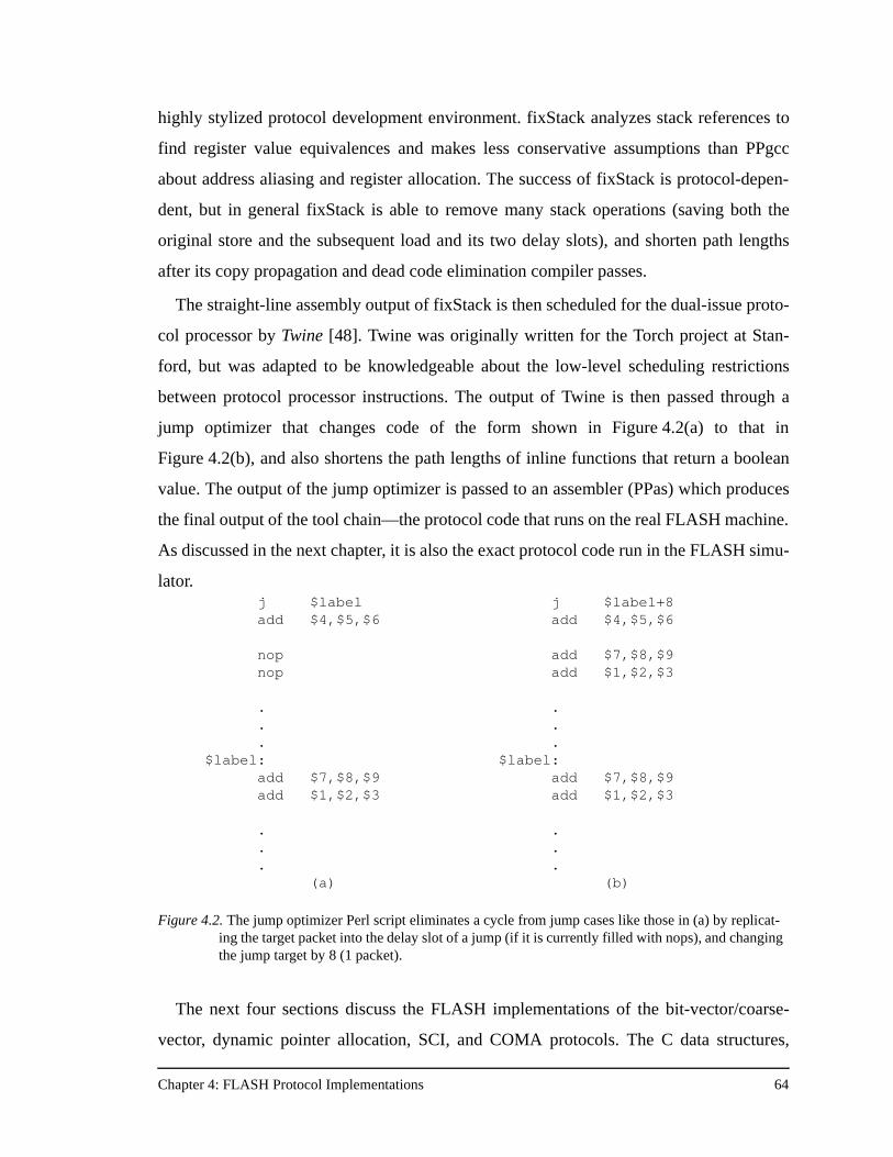
Chapter 4: FLASH Protocol Implementations 64
highly stylized protocol development environment. fixStack analyzes stack references to
find register value equivalences and makes less conservative assumptions than PPgcc
about address aliasing and register allocation. The success of fixStack is protocol-depen-
dent, but in general fixStack is able to remove many stack operations (saving both the
original store and the subsequent load and its two delay slots), and shorten path lengths
after its copy propagation and dead code elimination compiler passes.
The straight-line assembly output of fixStack is then scheduled for the dual-issue proto-
col processor by Twine [48]. Twine was originally written for the Torch project at Stan-
ford, but was adapted to be knowledgeable about the low-level scheduling restrictions
between protocol processor instructions. The output of Twine is then passed through a
jump optimizer that changes code of the form shown in Figure 4.2(a) to that in
Figure 4.2(b), and also shortens the path lengths of inline functions that return a boolean
value. The output of the jump optimizer is passed to an assembler (PPas) which produces
the final output of the tool chain—the protocol code that runs on the real FLASH machine.
As discussed in the next chapter, it is also the exact protocol code run in the FLASH simu-
lator.
The next four sections discuss the FLASH implementations of the bit-vector/coarse-
vector, dynamic pointer allocation, SCI, and COMA protocols. The C data structures,
j $labeladd $4,$5,$6
nopnop
.
.
.$label:
add $7,$8,$9add $1,$2,$3
.
.
.(a)
j $label+8add $4,$5,$6
add $7,$8,$9add $1,$2,$3
.
.
.$label:
add $7,$8,$9add $1,$2,$3
.
.
.(b)
Figure 4.2. The jump optimizer Perl script eliminates a cycle from jump cases like those in (a) by replicat-ing the target packet into the delay slot of a jump (if it is currently filled with nops), and changing the jump target by 8 (1 packet).
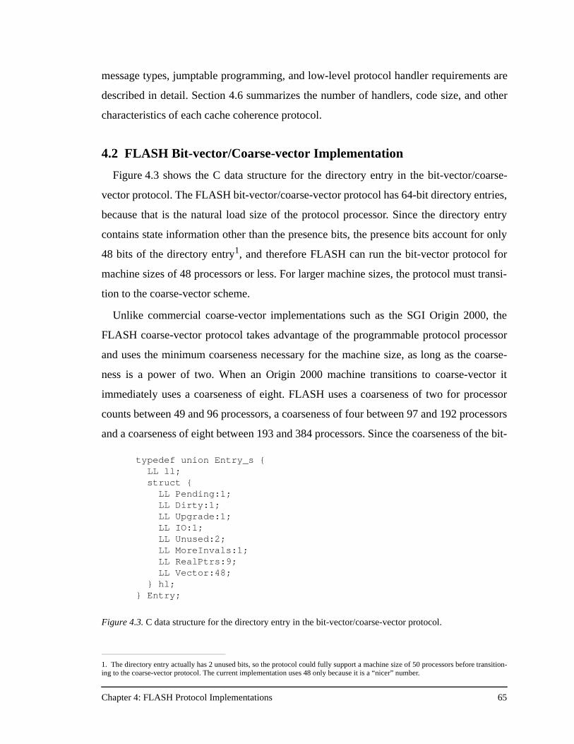
Chapter 4: FLASH Protocol Implementations 65
message types, jumptable programming, and low-level protocol handler requirements are
described in detail. Section 4.6 summarizes the number of handlers, code size, and other
characteristics of each cache coherence protocol.
4.2 FLASH Bit-vector/Coarse-vector Implementation
Figure 4.3 shows the C data structure for the directory entry in the bit-vector/coarse-
vector protocol. The FLASH bit-vector/coarse-vector protocol has 64-bit directory entries,
because that is the natural load size of the protocol processor. Since the directory entry
contains state information other than the presence bits, the presence bits account for only
48 bits of the directory entry1, and therefore FLASH can run the bit-vector protocol for
machine sizes of 48 processors or less. For larger machine sizes, the protocol must transi-
tion to the coarse-vector scheme.
Unlike commercial coarse-vector implementations such as the SGI Origin 2000, the
FLASH coarse-vector protocol takes advantage of the programmable protocol processor
and uses the minimum coarseness necessary for the machine size, as long as the coarse-
ness is a power of two. When an Origin 2000 machine transitions to coarse-vector it
immediately uses a coarseness of eight. FLASH uses a coarseness of two for processor
counts between 49 and 96 processors, a coarseness of four between 97 and 192 processors
and a coarseness of eight between 193 and 384 processors. Since the coarseness of the bit-
1. The directory entry actually has 2 unused bits, so the protocol could fully support a machine size of 50 processors before transition-ing to the coarse-vector protocol. The current implementation uses 48 only because it is a “nicer” number.
typedef union Entry_s { LL ll;
struct { LL Pending:1; LL Dirty:1; LL Upgrade:1; LL IO:1;
LL Unused:2; LL MoreInvals:1;
LL RealPtrs:9; LL Vector:48; } hl; } Entry;
Figure 4.3. C data structure for the directory entry in the bit-vector/coarse-vector protocol.
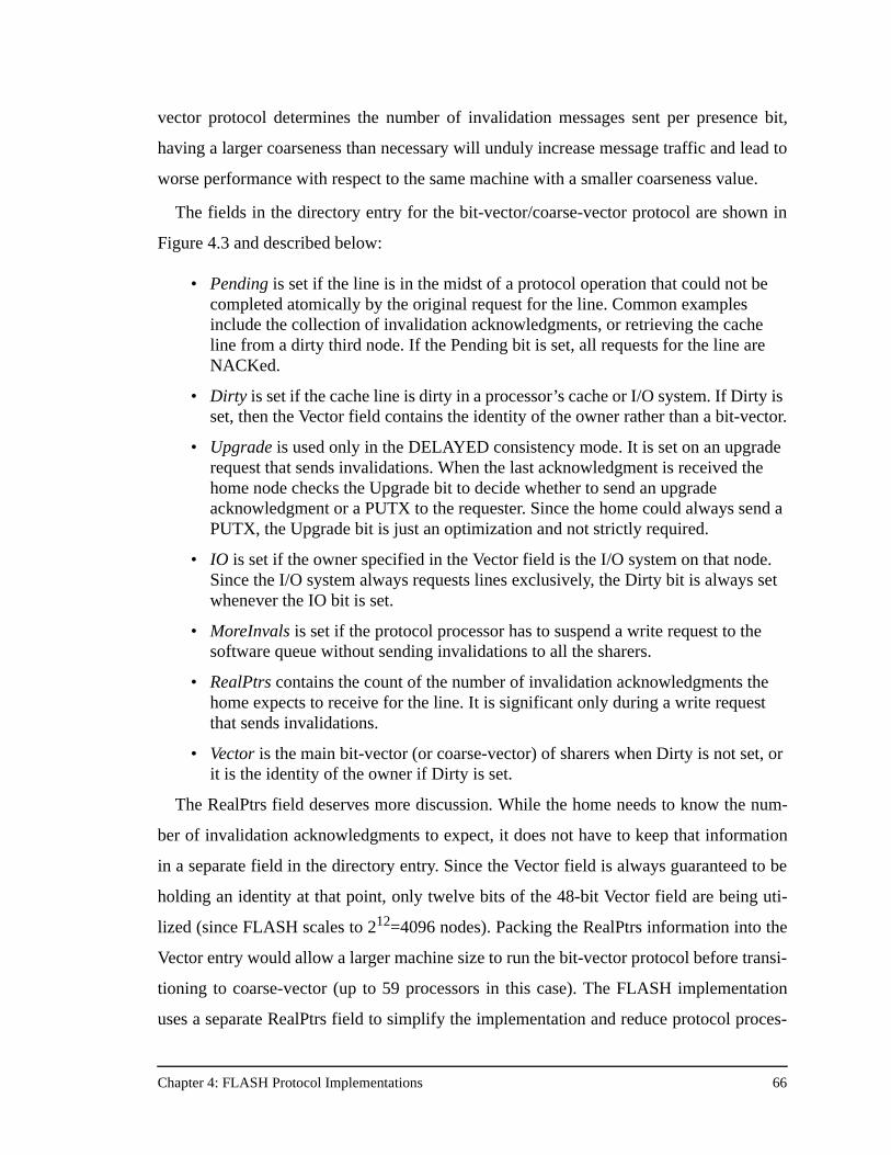
Chapter 4: FLASH Protocol Implementations 66
vector protocol determines the number of invalidation messages sent per presence bit,
having a larger coarseness than necessary will unduly increase message traffic and lead to
worse performance with respect to the same machine with a smaller coarseness value.
The fields in the directory entry for the bit-vector/coarse-vector protocol are shown in
Figure 4.3 and described below:
• Pending is set if the line is in the midst of a protocol operation that could not be completed atomically by the original request for the line. Common examples include the collection of invalidation acknowledgments, or retrieving the cache line from a dirty third node. If the Pending bit is set, all requests for the line are NACKed.
• Dirty is set if the cache line is dirty in a processor’s cache or I/O system. If Dirty is set, then the Vector field contains the identity of the owner rather than a bit-vector.
• Upgrade is used only in the DELAYED consistency mode. It is set on an upgrade request that sends invalidations. When the last acknowledgment is received the home node checks the Upgrade bit to decide whether to send an upgrade acknowledgment or a PUTX to the requester. Since the home could always send a PUTX, the Upgrade bit is just an optimization and not strictly required.
• IO is set if the owner specified in the Vector field is the I/O system on that node. Since the I/O system always requests lines exclusively, the Dirty bit is always set whenever the IO bit is set.
• MoreInvals is set if the protocol processor has to suspend a write request to the software queue without sending invalidations to all the sharers.
• RealPtrs contains the count of the number of invalidation acknowledgments the home expects to receive for the line. It is significant only during a write request that sends invalidations.
• Vector is the main bit-vector (or coarse-vector) of sharers when Dirty is not set, or it is the identity of the owner if Dirty is set.
The RealPtrs field deserves more discussion. While the home needs to know the num-
ber of invalidation acknowledgments to expect, it does not have to keep that information
in a separate field in the directory entry. Since the Vector field is always guaranteed to be
holding an identity at that point, only twelve bits of the 48-bit Vector field are being uti-
lized (since FLASH scales to 212=4096 nodes). Packing the RealPtrs information into the
Vector entry would allow a larger machine size to run the bit-vector protocol before transi-
tioning to coarse-vector (up to 59 processors in this case). The FLASH implementation
uses a separate RealPtrs field to simplify the implementation and reduce protocol proces-
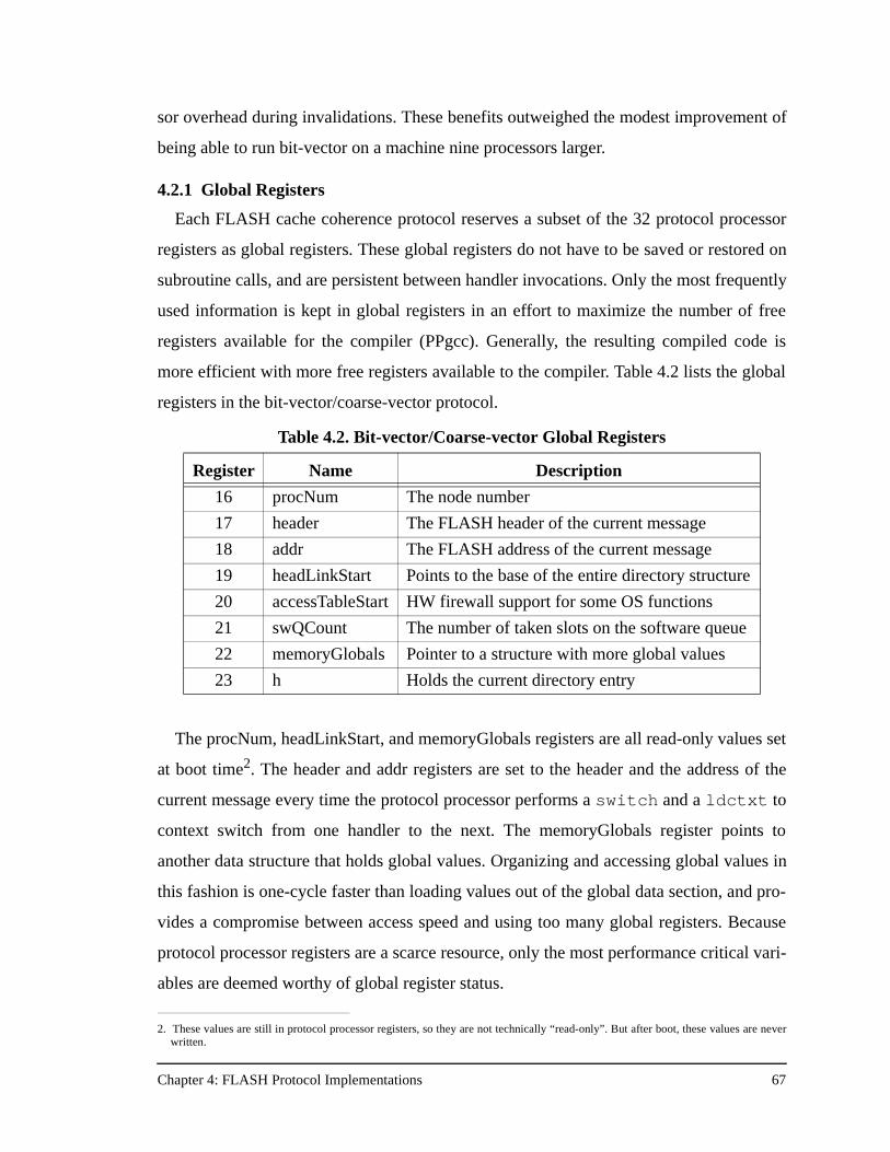
Chapter 4: FLASH Protocol Implementations 67
sor overhead during invalidations. These benefits outweighed the modest improvement of
being able to run bit-vector on a machine nine processors larger.
4.2.1 Global Registers
Each FLASH cache coherence protocol reserves a subset of the 32 protocol processor
registers as global registers. These global registers do not have to be saved or restored on
subroutine calls, and are persistent between handler invocations. Only the most frequently
used information is kept in global registers in an effort to maximize the number of free
registers available for the compiler (PPgcc). Generally, the resulting compiled code is
more efficient with more free registers available to the compiler. Table 4.2 lists the global
registers in the bit-vector/coarse-vector protocol.
The procNum, headLinkStart, and memoryGlobals registers are all read-only values set
at boot time2. The header and addr registers are set to the header and the address of the
current message every time the protocol processor performs a switch and a ldctxt to
context switch from one handler to the next. The memoryGlobals register points to
another data structure that holds global values. Organizing and accessing global values in
this fashion is one-cycle faster than loading values out of the global data section, and pro-
vides a compromise between access speed and using too many global registers. Because
protocol processor registers are a scarce resource, only the most performance critical vari-
ables are deemed worthy of global register status.
2. These values are still in protocol processor registers, so they are not technically “read-only”. But after boot, these values are neverwritten.
Table 4.2. Bit-vector/Coarse-vector Global Registers
Register Name Description
16 procNum The node number
17 header The FLASH header of the current message
18 addr The FLASH address of the current message
19 headLinkStart Points to the base of the entire directory structure
20 accessTableStart HW firewall support for some OS functions
21 swQCount The number of taken slots on the software queue
22 memoryGlobals Pointer to a structure with more global values
23 h Holds the current directory entry
Chapter 4: FLASH Protocol Implementations 68
4.2.2 Message Types
All FLASH protocols must have protocol handlers for both the local and remote vari-
ants of the seven processor-to-MAGIC commands listed in Table 3.2. The encoding of
these commands is fixed by the FLASH hardware, specifically the processor interface
(PI). The encoding and the number of network message types, however, are left up to the
protocol designer. The network message types for the bit-vector/coarse-vector protocol are
shown in Table 4.3. Including the support for both EAGER and DELAYED consistency
modes, cache-coherent I/O, and uncached operations to both main memory and I/O
devices, the bit-vector coarse-vector protocol uses 36 network message types. Many of the
message encodings are carefully chosen so that the network message types have the same
lower four bits as the corresponding processor request (since the processor message types
are only four bits long while the FLASH network message types are eight bits long). For
example the MSG_PUT message type is the response to a remote read request. This mes-
sage triggers the NIRemotePut handler, which is responsible for forwarding the PUT from
the NI to the PI to satisfy the cache miss. Because the lower four bits of MSG_PUT and
PI_DP_PUT_RPLY are the same (0xf) the protocol processor does not have to waste a
cycle changing the message type. Instead the very first instruction of the NIRemotePut
handler is a send to the PI.
Similar encoding tricks are used with the MSG_INVAL and MSG_INVAL_ACK mes-
sage types. The message types are the same, so how does the jumptable know whether to
dispatch the NIInval handler or the NIInvalAck handler? The answer is that in the bit-vec-
tor/coarse-vector protocol, invalidation messages arrive only at remote nodes, and invali-
dation acknowledgments arrive only at local nodes. The jumptable uses the local/remote
bit to know which routine to dispatch. Having the same message type for both
MSG_INVAL and MSG_INVAL_ACK saves a cycle in the invalidation handler.
The cache-coherent I/O support in the protocol also takes advantage of message encod-
ing to re-use the same message types and the same protocol handlers as the base cache
coherence protocol. The FLASH I/O system makes only exclusive requests for cache
lines, and it only operates in DELAYED mode, meaning all invalidation acknowledg-
ments must be received before the home node can return data to the I/O system. The
FLASH I/O system places the device number of the I/O device making the DMA request
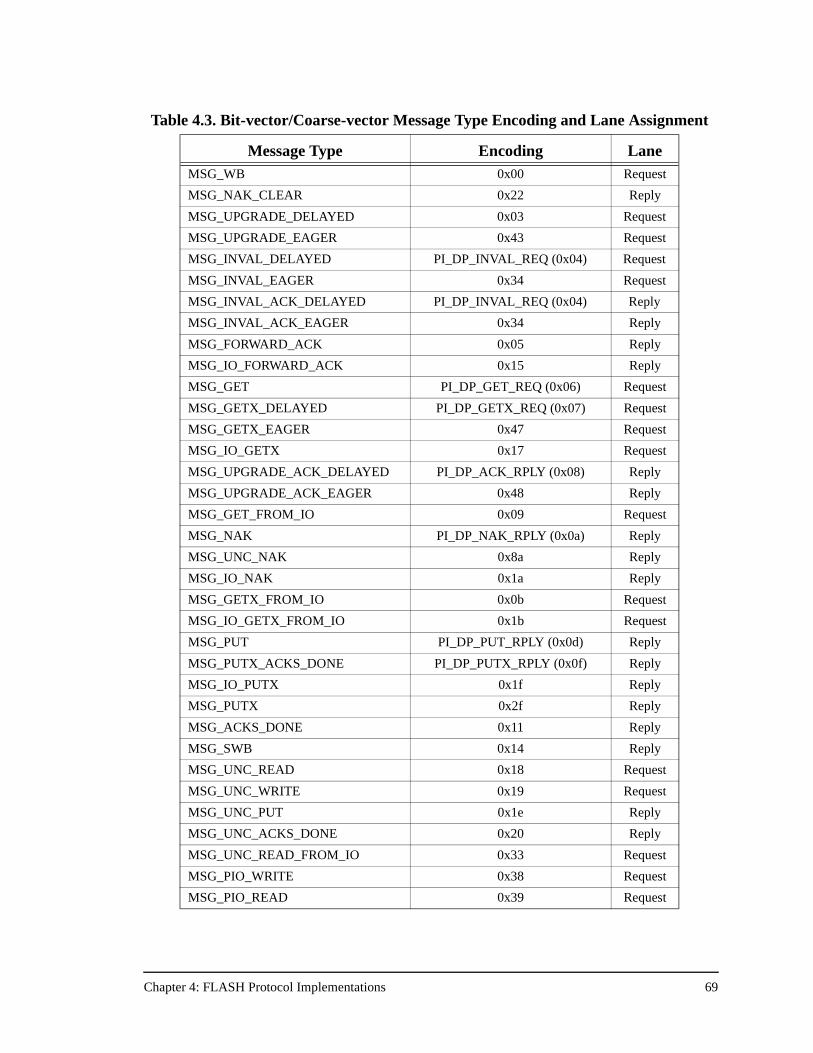
Chapter 4: FLASH Protocol Implementations 69
Table 4.3. Bit-vector/Coarse-vector Message Type Encoding and Lane Assignment
Message Type Encoding LaneMSG_WB 0x00 Request
MSG_NAK_CLEAR 0x22 Reply
MSG_UPGRADE_DELAYED 0x03 Request
MSG_UPGRADE_EAGER 0x43 Request
MSG_INVAL_DELAYED PI_DP_INVAL_REQ (0x04) Request
MSG_INVAL_EAGER 0x34 Request
MSG_INVAL_ACK_DELAYED PI_DP_INVAL_REQ (0x04) Reply
MSG_INVAL_ACK_EAGER 0x34 Reply
MSG_FORWARD_ACK 0x05 Reply
MSG_IO_FORWARD_ACK 0x15 Reply
MSG_GET PI_DP_GET_REQ (0x06) Request
MSG_GETX_DELAYED PI_DP_GETX_REQ (0x07) Request
MSG_GETX_EAGER 0x47 Request
MSG_IO_GETX 0x17 Request
MSG_UPGRADE_ACK_DELAYED PI_DP_ACK_RPLY (0x08) Reply
MSG_UPGRADE_ACK_EAGER 0x48 Reply
MSG_GET_FROM_IO 0x09 Request
MSG_NAK PI_DP_NAK_RPLY (0x0a) Reply
MSG_UNC_NAK 0x8a Reply
MSG_IO_NAK 0x1a Reply
MSG_GETX_FROM_IO 0x0b Request
MSG_IO_GETX_FROM_IO 0x1b Request
MSG_PUT PI_DP_PUT_RPLY (0x0d) Reply
MSG_PUTX_ACKS_DONE PI_DP_PUTX_RPLY (0x0f) Reply
MSG_IO_PUTX 0x1f Reply
MSG_PUTX 0x2f Reply
MSG_ACKS_DONE 0x11 Reply
MSG_SWB 0x14 Reply
MSG_UNC_READ 0x18 Request
MSG_UNC_WRITE 0x19 Request
MSG_UNC_PUT 0x1e Reply
MSG_UNC_ACKS_DONE 0x20 Reply
MSG_UNC_READ_FROM_IO 0x33 Request
MSG_PIO_WRITE 0x38 Request
MSG_PIO_READ 0x39 Request
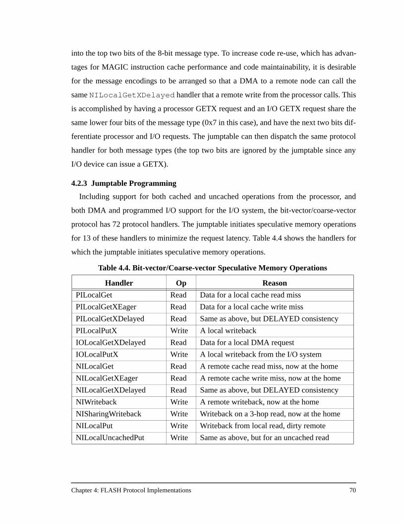
Chapter 4: FLASH Protocol Implementations 70
into the top two bits of the 8-bit message type. To increase code re-use, which has advan-
tages for MAGIC instruction cache performance and code maintainability, it is desirable
for the message encodings to be arranged so that a DMA to a remote node can call the
same NILocalGetXDelayed handler that a remote write from the processor calls. This
is accomplished by having a processor GETX request and an I/O GETX request share the
same lower four bits of the message type (0x7 in this case), and have the next two bits dif-
ferentiate processor and I/O requests. The jumptable can then dispatch the same protocol
handler for both message types (the top two bits are ignored by the jumptable since any
I/O device can issue a GETX).
4.2.3 Jumptable Programming
Including support for both cached and uncached operations from the processor, and
both DMA and programmed I/O support for the I/O system, the bit-vector/coarse-vector
protocol has 72 protocol handlers. The jumptable initiates speculative memory operations
for 13 of these handlers to minimize the request latency. Table 4.4 shows the handlers for
which the jumptable initiates speculative memory operations.
Table 4.4. Bit-vector/Coarse-vector Speculative Memory Operations
Handler Op Reason
PILocalGet Read Data for a local cache read miss
PILocalGetXEager Read Data for a local cache write miss
PILocalGetXDelayed Read Same as above, but DELAYED consistency
PILocalPutX Write A local writeback
IOLocalGetXDelayed Read Data for a local DMA request
IOLocalPutX Write A local writeback from the I/O system
NILocalGet Read A remote cache read miss, now at the home
NILocalGetXEager Read A remote cache write miss, now at the home
NILocalGetXDelayed Read Same as above, but DELAYED consistency
NIWriteback Write A remote writeback, now at the home
NISharingWriteback Write Writeback on a 3-hop read, now at the home
NILocalPut Write Writeback from local read, dirty remote
NILocalUncachedPut Write Same as above, but for an uncached read
Chapter 4: FLASH Protocol Implementations 71
4.2.4 Additional Considerations
Section 2.3 discusses the potential increase in message traffic associated with the transi-
tion from the bit-vector protocol to the coarse-vector protocol. The increase is the result of
imprecise sharing information in the directory entry, causing invalidations to be sent to
more nodes than are strictly necessary. The same imprecise sharing information leads to
another problem in the coarse-vector protocol—what to do about upgrade requests.
Upgrade requests are write requests from the processor where the processor has a
shared copy of the line in its cache. In this case the processor needs only a write acknowl-
edgment from the memory system, since the cache already has the correct data. Upgrades
are an optimization since the processor could always issue a normal write miss (GETX),
though the access to main memory in that case would be unnecessary. Memory bandwidth
savings and, in the case of a remote write miss, network bandwidth savings are the funda-
mental advantage of using upgrades for write misses to shared lines. The bit-vector proto-
col dispatches upgrade protocol handlers for processor upgrade requests, but
complications arise in the coarse-vector protocol because of its imprecise sharing informa-
tion.
For example, if the coarseness is four and the Vector field of the directory entry is 1,
then at least one of the first four processors in the machine has a shared copy of the data. If
an upgrade request arrives at the home from processor 0, is it safe to reply with an upgrade
acknowledgment? The home node cannot be sure that processor 0 has a shared copy of the
line, since it knows only that some processor in the first group of four has a shared copy. It
is true that in the common case, processor 0 does indeed have a shared copy, and the cor-
rect action is to issue an upgrade acknowledgment to processor 0 and invalidations to the
other three processors in the group. But via a more complicated protocol case, it is possi-
ble for this upgrade request to be arriving at the home when it is another processor in the
group, and only that processor, that has the shared copy.
What happens if the home issues an upgrade acknowledgment to processor 0 in that
case? The results are highly implementation dependent. On FLASH, that acknowledgment
would be turned into a NACK by the processor interface on processor 0, because for this
case to arise an invalidation message must have arrived while the upgrade request was
outstanding. The Conflict Resolution Table (CRT) in the processor interface tracks this
Chapter 4: FLASH Protocol Implementations 72
event and converts the acknowledgment for that upgrade into a NACK. The processor will
then retry that upgrade as a GETX write miss. So at this point there is still no problem.
The problem is that when this GETX gets to the home node, the directory entry is now in
the Dirty state, and the owner is the requester! This is normally an invalid condition in the
protocol code because the exclusive owner should never be requesting the cache line that
it owns. The protocol could ignore this error condition and send the PUTX anyway, but
this may be undesirable because it could mask real protocol errors.
Unfortunately, this same case gets worse when the processor has the capability of issu-
ing speculative memory references like the MIPS R10000 used in FLASH. With specula-
tive processors, the original upgrade request above may get NACKed back to the
processor, but then never retried. If the upgrade request was issued speculatively then it is
possible for that to happen. At this point the directory entry says the line is Dirty and the
owner is processor 0, but processor 0 does not have the line and may never request it
again. This is a deadlock condition waiting to happen. The next request for that cache line
will be forwarded to processor 0, which does not have the line. That request will be
NACKed and retried, assuming that the line must be in transit back to the home from pro-
cessor 0 (this transient case is quite common). However, in this case, the retried request
will again be forwarded to processor 0, NACKed, and retried again ad infinitum. Dead-
lock.
There are two solutions to this problem. The first is a complicated protocol change that
involves holding off invalidation messages if an upgrade is outstanding until the upgrade
response is returned. This change is necessary only for coarseness greater than one. This
change is non-trivial as it now requires state to be kept for the previously stateless invali-
dation sequence. The change may also affect performance since the system is holding onto
invalidations and therefore not completing other writes as quickly as it was under the bit-
vector protocol. The second solution is to simply turn off upgrades when the coarseness of
the protocol is greater than one. This is the solution adopted in the FLASH implementa-
tion. The FLASH system does not “turn off” upgrades literally, since the processor still
issues upgrade requests. Instead the Jumptable simply dispatches the GETX handler when
it receives an upgrade request from the processor. Recall that this is always correct, with
the only downsides being an increase in main memory and network bandwidth. The
Chapter 4: FLASH Protocol Implementations 73
results in Chapter 6 show that for parallel programs running on large machines (coarseness
> 1) the FLASH network bandwidth is never a performance concern. The increase in main
memory bandwidth also has a negligible effect on performance as most codes are domi-
nated by the occupancy of the protocol processor (controller bandwidth) and not memory
bandwidth.
If protocol processor latency is defined as the number of cycles to the first send
instruction, and protocol processor occupancy is defined as the number of cycles from the
start of the handler to the end, the bit-vector/coarse-vector protocol in general has the low-
est protocol processor latencies and occupancies of any of the protocols because it
employs only simple bit manipulations to keep track of sharing information. However, this
direct protocol overhead is only one of the components of overall protocol performance
and robustness. The coarse-vector protocol retains the low direct protocol overhead of bit-
vector, but loses precise sharing information which can increase message traffic in large
systems. This trade-off is at the core of the bit-vector/coarse-vector performance results in
Chapter 6.
4.3 FLASH Dynamic Pointer Allocation Protocol Implementation
Unlike the bit-vector/coarse-vector protocol, the dynamic pointer allocation protocol
maintains two data structures to track sharing information. The first is the directory entry,
and the second is a block of storage for pointers called the pointer/link store. On read and
write requests, the home node allocates pointers from the pointer/link store to use as ele-
ments for a linked list of sharers that hang off each directory entry. On replacement hint
requests the home searches the sharing list and removes the requester, returning the list
element to the pointer/link store for future re-use. Because the directory entry serves as the
head of the linked list, in the dynamic pointer allocation protocol the directory entry is
referred to as the directory header.
The C data structure for the directory header in the dynamic pointer allocation protocol
is shown in Figure 4.4. As in the bit-vector protocol, the directory entry for the dynamic
pointer allocation is 64 bits wide. Each field in the directory header is described below:
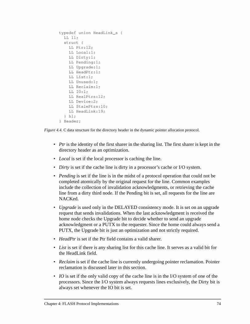
Chapter 4: FLASH Protocol Implementations 74
• Ptr is the identity of the first sharer in the sharing list. The first sharer is kept in the directory header as an optimization.
• Local is set if the local processor is caching the line.
• Dirty is set if the cache line is dirty in a processor’s cache or I/O system.
• Pending is set if the line is in the midst of a protocol operation that could not be completed atomically by the original request for the line. Common examples include the collection of invalidation acknowledgments, or retrieving the cache line from a dirty third node. If the Pending bit is set, all requests for the line are NACKed.
• Upgrade is used only in the DELAYED consistency mode. It is set on an upgrade request that sends invalidations. When the last acknowledgment is received the home node checks the Upgrade bit to decide whether to send an upgrade acknowledgment or a PUTX to the requester. Since the home could always send a PUTX, the Upgrade bit is just an optimization and not strictly required.
• HeadPtr is set if the Ptr field contains a valid sharer.
• List is set if there is any sharing list for this cache line. It serves as a valid bit for the HeadLink field.
• Reclaim is set if the cache line is currently undergoing pointer reclamation. Pointer reclamation is discussed later in this section.
• IO is set if the only valid copy of the cache line is in the I/O system of one of the processors. Since the I/O system always requests lines exclusively, the Dirty bit is always set whenever the IO bit is set.
typedef union HeadLink_s { LL ll;
struct { LL Ptr:12;
LL Local:1; LL Dirty:1; LL Pending:1; LL Upgrade:1; LL HeadPtr:1; LL List:1;
LL Unused:1; LL Reclaim:1;
LL IO:1; LL RealPtrs:12;
LL Device:2; LL StalePtrs:10; LL HeadLink:19;
} hl; } Header;
Figure 4.4. C data structure for the directory header in the dynamic pointer allocation protocol.
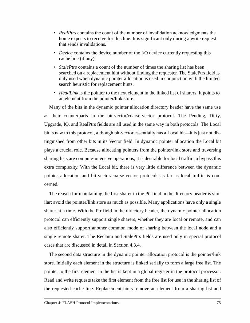
Chapter 4: FLASH Protocol Implementations 75
• RealPtrs contains the count of the number of invalidation acknowledgments the home expects to receive for this line. It is significant only during a write request that sends invalidations.
• Device contains the device number of the I/O device currently requesting this cache line (if any).
• StalePtrs contains a count of the number of times the sharing list has been searched on a replacement hint without finding the requester. The StalePtrs field is only used when dynamic pointer allocation is used in conjunction with the limited search heuristic for replacement hints.
• HeadLink is the pointer to the next element in the linked list of sharers. It points to an element from the pointer/link store.
Many of the bits in the dynamic pointer allocation directory header have the same use
as their counterparts in the bit-vector/coarse-vector protocol. The Pending, Dirty,
Upgrade, IO, and RealPtrs fields are all used in the same way in both protocols. The Local
bit is new to this protocol, although bit-vector essentially has a Local bit—it is just not dis-
tinguished from other bits in its Vector field. In dynamic pointer allocation the Local bit
plays a crucial role. Because allocating pointers from the pointer/link store and traversing
sharing lists are compute-intensive operations, it is desirable for local traffic to bypass this
extra complexity. With the Local bit, there is very little difference between the dynamic
pointer allocation and bit-vector/coarse-vector protocols as far as local traffic is con-
cerned.
The reason for maintaining the first sharer in the Ptr field in the directory header is sim-
ilar: avoid the pointer/link store as much as possible. Many applications have only a single
sharer at a time. With the Ptr field in the directory header, the dynamic pointer allocation
protocol can efficiently support single sharers, whether they are local or remote, and can
also efficiently support another common mode of sharing between the local node and a
single remote sharer. The Reclaim and StalePtrs fields are used only in special protocol
cases that are discussed in detail in Section 4.3.4.
The second data structure in the dynamic pointer allocation protocol is the pointer/link
store. Initially each element in the structure is linked serially to form a large free list. The
pointer to the first element in the list is kept in a global register in the protocol processor.
Read and write requests take the first element from the free list for use in the sharing list of
the requested cache line. Replacement hints remove an element from a sharing list and
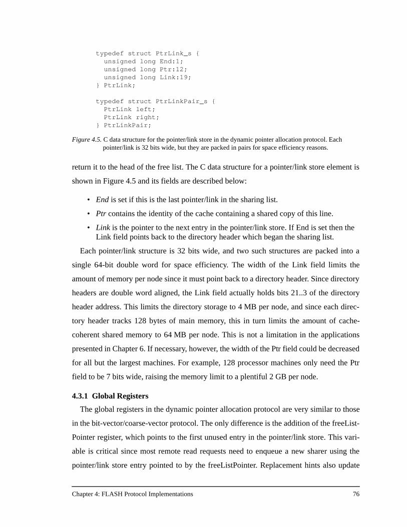
Chapter 4: FLASH Protocol Implementations 76
return it to the head of the free list. The C data structure for a pointer/link store element is
shown in Figure 4.5 and its fields are described below:
• End is set if this is the last pointer/link in the sharing list.
• Ptr contains the identity of the cache containing a shared copy of this line.
• Link is the pointer to the next entry in the pointer/link store. If End is set then the Link field points back to the directory header which began the sharing list.
Each pointer/link structure is 32 bits wide, and two such structures are packed into a
single 64-bit double word for space efficiency. The width of the Link field limits the
amount of memory per node since it must point back to a directory header. Since directory
headers are double word aligned, the Link field actually holds bits 21..3 of the directory
header address. This limits the directory storage to 4 MB per node, and since each direc-
tory header tracks 128 bytes of main memory, this in turn limits the amount of cache-
coherent shared memory to 64 MB per node. This is not a limitation in the applications
presented in Chapter 6. If necessary, however, the width of the Ptr field could be decreased
for all but the largest machines. For example, 128 processor machines only need the Ptr
field to be 7 bits wide, raising the memory limit to a plentiful 2 GB per node.
4.3.1 Global Registers
The global registers in the dynamic pointer allocation protocol are very similar to those
in the bit-vector/coarse-vector protocol. The only difference is the addition of the freeList-
Pointer register, which points to the first unused entry in the pointer/link store. This vari-
able is critical since most remote read requests need to enqueue a new sharer using the
pointer/link store entry pointed to by the freeListPointer. Replacement hints also update
typedef struct PtrLink_s { unsigned long End:1; unsigned long Ptr:12;
unsigned long Link:19; } PtrLink; typedef struct PtrLinkPair_s {
PtrLink left; PtrLink right;
} PtrLinkPair;
Figure 4.5. C data structure for the pointer/link store in the dynamic pointer allocation protocol. Each pointer/link is 32 bits wide, but they are packed in pairs for space efficiency reasons.
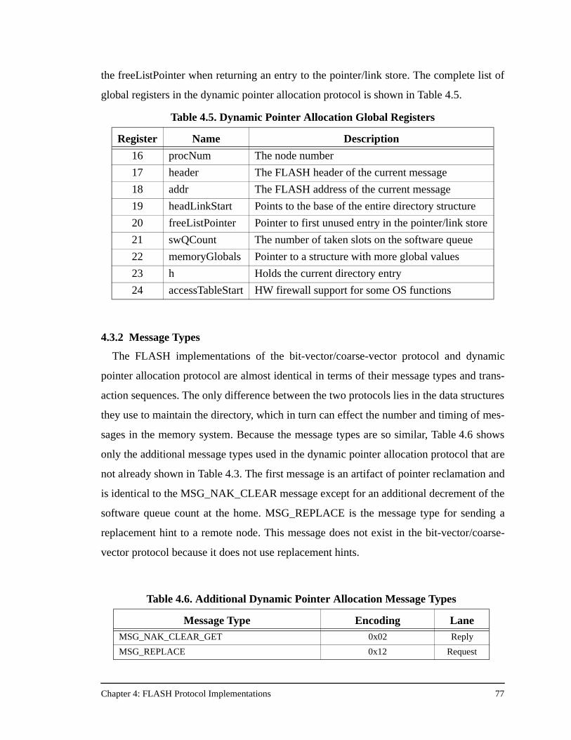
Chapter 4: FLASH Protocol Implementations 77
the freeListPointer when returning an entry to the pointer/link store. The complete list of
global registers in the dynamic pointer allocation protocol is shown in Table 4.5.
4.3.2 Message Types
The FLASH implementations of the bit-vector/coarse-vector protocol and dynamic
pointer allocation protocol are almost identical in terms of their message types and trans-
action sequences. The only difference between the two protocols lies in the data structures
they use to maintain the directory, which in turn can effect the number and timing of mes-
sages in the memory system. Because the message types are so similar, Table 4.6 shows
only the additional message types used in the dynamic pointer allocation protocol that are
not already shown in Table 4.3. The first message is an artifact of pointer reclamation and
is identical to the MSG_NAK_CLEAR message except for an additional decrement of the
software queue count at the home. MSG_REPLACE is the message type for sending a
replacement hint to a remote node. This message does not exist in the bit-vector/coarse-
vector protocol because it does not use replacement hints.
Table 4.5. Dynamic Pointer Allocation Global Registers
Register Name Description
16 procNum The node number
17 header The FLASH header of the current message
18 addr The FLASH address of the current message
19 headLinkStart Points to the base of the entire directory structure
20 freeListPointer Pointer to first unused entry in the pointer/link store
21 swQCount The number of taken slots on the software queue
22 memoryGlobals Pointer to a structure with more global values
23 h Holds the current directory entry
24 accessTableStart HW firewall support for some OS functions
Table 4.6. Additional Dynamic Pointer Allocation Message Types
Message Type Encoding LaneMSG_NAK_CLEAR_GET 0x02 Reply
MSG_REPLACE 0x12 Request
Chapter 4: FLASH Protocol Implementations 78
4.3.3 Jumptable Programming
Including support for both cached and uncached operations from the processor, and
both DMA and programmed I/O support for the I/O system, the dynamic pointer alloca-
tion protocol has 77 protocol handlers. The 5 additional handlers over the bit-vec-
tor/coarse-vector protocol include replacement hint handlers and more software queue
handlers stemming from the more complicated invalidation code. The jumptable initiates
speculative memory operations for exactly the same 13 handlers shown in Table 4.4.
4.3.4 Additional Considerations
Section 2.4 discusses the process of pointer reclamation in some detail. Pointer recla-
mation is necessary only when all the elements in the pointer/link store are being used in
sharing lists. At that point, an element is picked at random from the pointer/link store and
its list is followed back to its initial directory header. Then the entire list is invalidated,
reclaiming all its pointers by placing them back on the free list.
The reclamation implementation on FLASH is done within the context of normal proto-
col transactions. The only additional feature necessary is the Reclaim bit in the directory
header. The protocol processor sets the Reclaim bit, then sends out normal invalidation
messages to every sharer on the sharing list. Invalidation acknowledgments are collected
as normal. When the last invalidation acknowledgment arrives, normally the protocol
takes some final action like responding with data in DELAYED consistency mode, or dec-
rementing a fence count in EAGER consistency mode. In this case, however, either of
these actions would be improper since the invalidation sequence was not initiated by a
processor, but by the memory system. The NIInvalAck handler is simply modified to
check the Reclaim bit, and if set, silently clear the Pending bit without taking any other
action.
In practice, pointer reclamation is not something to worry about as long as the system
employs replacement hints. By sizing the pointer/link store appropriately, reclamation can
be made an extremely rare event. In the results presented in Chapter 6, pointer reclamation
never occurred.
Aside from pointer reclamation, the other major difference between the bit-vec-
tor/coarse-vector protocol and the dynamic pointer allocation protocol is the use of
Chapter 4: FLASH Protocol Implementations 79
replacement hints. Replacement hints are necessary to keep the steady bidirectional flow
of list elements to and from the pointer/link store. They are the means by which the
dynamic pointer allocation can retain precise sharing information at large machine sizes.
However, replacement hints present special problems with long sharing lists. For example,
in a 128 processor machine, a particular cache line may be shared by all processors. A
replacement hint arriving at the home node must linearly search through the sharing list
until it finds the requester. This search can consume precious protocol processor cycles for
something which does not have a direct benefit to the running application. A new perfor-
mance problem has arisen out of the need to avoid pointer reclamation by using replace-
ment hints, and the fact that those replacement hints can result in occupancy-induced
contention and hot-spotting in the memory system at large machine sizes.
The FLASH solution to this problem is to employ a limited search heuristic. Instead of
searching the entire sharing list on every replacement hint, the FLASH implementation
searches only a small, fixed number of sharers. For the protocol results presented in Chap-
ter 6, the maximum number of sharers searched is eight. If the requester is found, the
replacement hint behaves just as it does in a full list search. If, however, the requester is
not found within the first eight sharers, the protocol increments the StalePtrs field in the
directory header. To keep the algorithm stable, when StalePtrs reaches a threshold value
(currently 256) it is reset to 0 and the entire list is invalidated exactly as in pointer recla-
mation mode above. The performance improvement from using limited pointers is so sub-
stantial that it has become the default mode of operation for the dynamic pointer allocation
protocol. For example, at 128 processors FFT runs 70% faster with limited search.
When dynamic pointer allocation can avoid using the pointer/link store, the direct over-
head of the protocol is approximately the same as the bit-vector/coarse-vector protocol.
Pointer/link store operations such as enqueueing a new sharer, searching the list on
replacement hints, and invalidating a long sharing list are much more costly than their bit-
vector equivalents. In the bit-vector protocol to “enqueue” a sharer just means setting a
single bit. There are no replacement hints to worry about, and an invalidation is sent out
every 8 cycles in the bit-vector protocol versus every 15 cycles in dynamic pointer alloca-
tion. Nonetheless, it is the pointer/link store that makes dynamic pointer allocation scal-
able, and a potentially superior protocol at larger machine sizes.
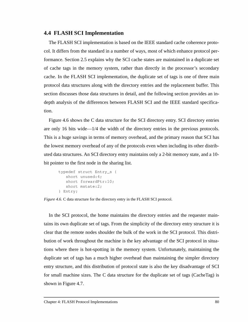
Chapter 4: FLASH Protocol Implementations 80
4.4 FLASH SCI Implementation
The FLASH SCI implementation is based on the IEEE standard cache coherence proto-
col. It differs from the standard in a number of ways, most of which enhance protocol per-
formance. Section 2.5 explains why the SCI cache states are maintained in a duplicate set
of cache tags in the memory system, rather than directly in the processor’s secondary
cache. In the FLASH SCI implementation, the duplicate set of tags is one of three main
protocol data structures along with the directory entries and the replacement buffer. This
section discusses those data structures in detail, and the following section provides an in-
depth analysis of the differences between FLASH SCI and the IEEE standard specifica-
tion.
Figure 4.6 shows the C data structure for the SCI directory entry. SCI directory entries
are only 16 bits wide—1/4 the width of the directory entries in the previous protocols.
This is a huge savings in terms of memory overhead, and the primary reason that SCI has
the lowest memory overhead of any of the protocols even when including its other distrib-
uted data structures. An SCI directory entry maintains only a 2-bit memory state, and a 10-
bit pointer to the first node in the sharing list.
In the SCI protocol, the home maintains the directory entries and the requester main-
tains its own duplicate set of tags. From the simplicity of the directory entry structure it is
clear that the remote nodes shoulder the bulk of the work in the SCI protocol. This distri-
bution of work throughout the machine is the key advantage of the SCI protocol in situa-
tions where there is hot-spotting in the memory system. Unfortunately, maintaining the
duplicate set of tags has a much higher overhead than maintaining the simpler directory
entry structure, and this distribution of protocol state is also the key disadvantage of SCI
for small machine sizes. The C data structure for the duplicate set of tags (CacheTag) is
shown in Figure 4.7.
typedef struct Entry_s { short unused:4; short forwardPtr:10;
short mstate:2; } Entry;
Figure 4.6. C data structure for the directory entry in the FLASH SCI protocol.
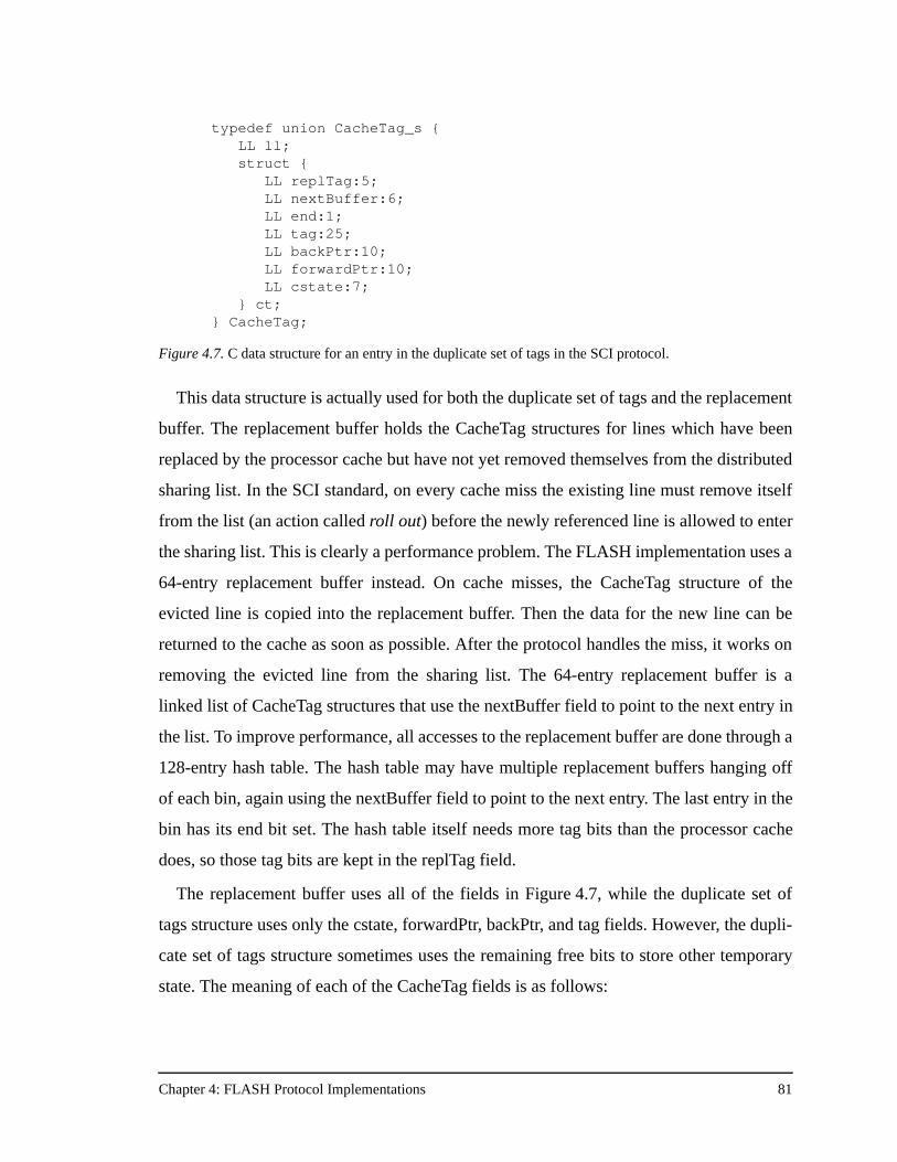
Chapter 4: FLASH Protocol Implementations 81
This data structure is actually used for both the duplicate set of tags and the replacement
buffer. The replacement buffer holds the CacheTag structures for lines which have been
replaced by the processor cache but have not yet removed themselves from the distributed
sharing list. In the SCI standard, on every cache miss the existing line must remove itself
from the list (an action called roll out) before the newly referenced line is allowed to enter
the sharing list. This is clearly a performance problem. The FLASH implementation uses a
64-entry replacement buffer instead. On cache misses, the CacheTag structure of the
evicted line is copied into the replacement buffer. Then the data for the new line can be
returned to the cache as soon as possible. After the protocol handles the miss, it works on
removing the evicted line from the sharing list. The 64-entry replacement buffer is a
linked list of CacheTag structures that use the nextBuffer field to point to the next entry in
the list. To improve performance, all accesses to the replacement buffer are done through a
128-entry hash table. The hash table may have multiple replacement buffers hanging off
of each bin, again using the nextBuffer field to point to the next entry. The last entry in the
bin has its end bit set. The hash table itself needs more tag bits than the processor cache
does, so those tag bits are kept in the replTag field.
The replacement buffer uses all of the fields in Figure 4.7, while the duplicate set of
tags structure uses only the cstate, forwardPtr, backPtr, and tag fields. However, the dupli-
cate set of tags structure sometimes uses the remaining free bits to store other temporary
state. The meaning of each of the CacheTag fields is as follows:
typedef union CacheTag_s { LL ll;
struct { LL replTag:5; LL nextBuffer:6;
LL end:1; LL tag:25; LL backPtr:10; LL forwardPtr:10; LL cstate:7; } ct; } CacheTag;
Figure 4.7. C data structure for an entry in the duplicate set of tags in the SCI protocol.
Chapter 4: FLASH Protocol Implementations 82
• replTag is the extra tag needed for the replacement buffer hash table. The duplicate tag structure also uses this field to indicate upgrade requests that have not yet returned from the home.
• nextBuffer points to the next replacement buffer entry in either the free list, or the hash table bin, depending on where the entry is linked.
• end is set if this replacement buffer entry is the last in the list.
• tag is the duplicate tag from the processor cache for this address.
• backPtr points to the previous node in the sharing list, or to the home node if this is the first entry in the list.
• forwardPtr points to the next node in the sharing list, or a special null value if it is the last entry in the list.
• cstate is the cache state of the current line. There are many more than the three simple invalid, shared, and dirty states. The cstate field corresponds to the SCI state of the cache line, and there are many different stable and transient states. See below.
4.4.1 FLASH SCI Cache States
The SCI protocol specification defines 128 cache states. Many of these states are
unused in the specification, and marked as reserved for future use. The FLASH SCI
implementation uses many of the same states defined in the implementation. In addition,
the FLASH implementation adds some new states in the reserved types, and does not use
the remainder of the defined states (similar to most SCI implementations). Table 4.7 lists
the FLASH SCI cache states using the IEEE standard nomenclature, and indicates whether
this is an IEEE standard cache state, or a FLASH-specific one.
Many of the new cache states arise from implementation constraints when writing an
SCI protocol for FLASH. Certain protocol operations must be changed, or cannot be sup-
ported altogether on FLASH, so alternate solutions had to invented. The next section
details the differences between the FLASH SCI implementation and the IEEE standard. In
the course of this discussion, many of the unique characteristics of the FLASH SCI imple-
mentation manifest themselves.
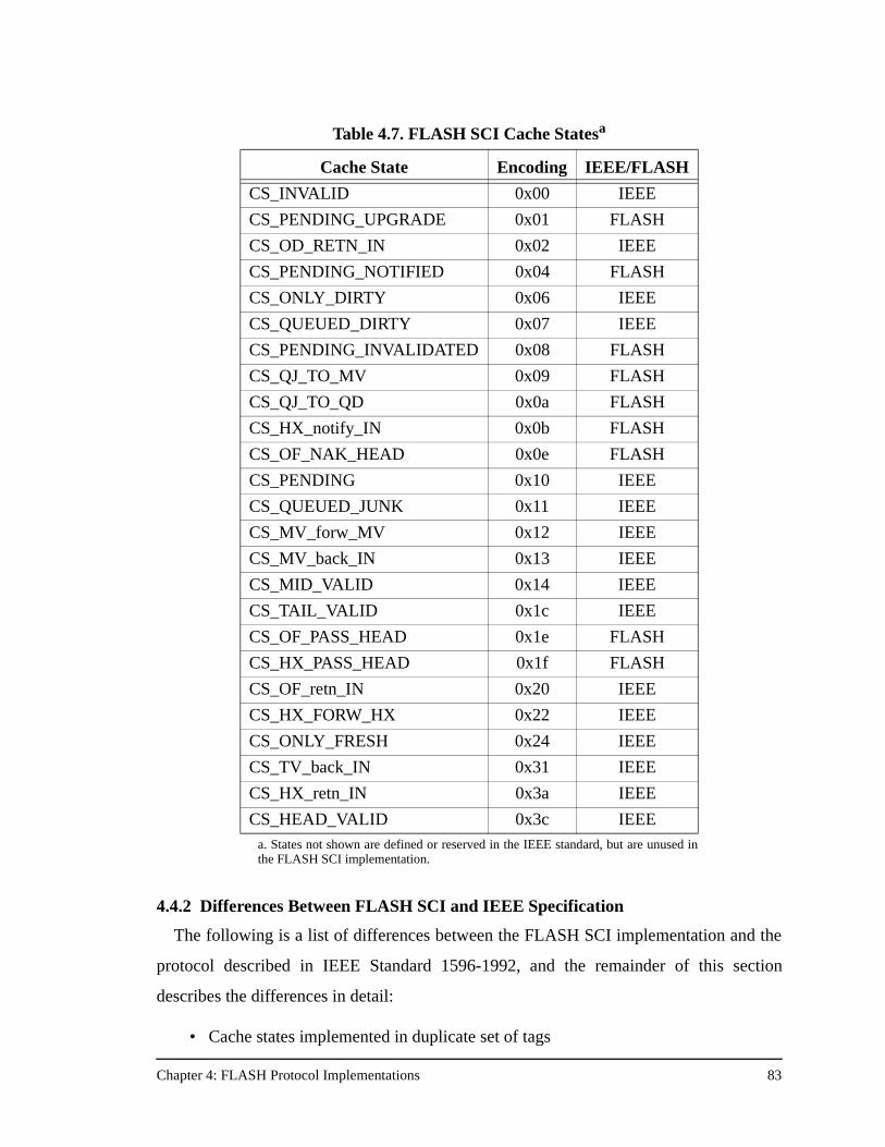
Chapter 4: FLASH Protocol Implementations 83
4.4.2 Differences Between FLASH SCI and IEEE Specification
The following is a list of differences between the FLASH SCI implementation and the
protocol described in IEEE Standard 1596-1992, and the remainder of this section
describes the differences in detail:
• Cache states implemented in duplicate set of tags
Table 4.7. FLASH SCI Cache Statesa
a. States not shown are defined or reserved in the IEEE standard, but are unused inthe FLASH SCI implementation.
Cache State Encoding IEEE/FLASH
CS_INVALID 0x00 IEEE
CS_PENDING_UPGRADE 0x01 FLASH
CS_OD_RETN_IN 0x02 IEEE
CS_PENDING_NOTIFIED 0x04 FLASH
CS_ONLY_DIRTY 0x06 IEEE
CS_QUEUED_DIRTY 0x07 IEEE
CS_PENDING_INVALIDATED 0x08 FLASH
CS_QJ_TO_MV 0x09 FLASH
CS_QJ_TO_QD 0x0a FLASH
CS_HX_notify_IN 0x0b FLASH
CS_OF_NAK_HEAD 0x0e FLASH
CS_PENDING 0x10 IEEE
CS_QUEUED_JUNK 0x11 IEEE
CS_MV_forw_MV 0x12 IEEE
CS_MV_back_IN 0x13 IEEE
CS_MID_VALID 0x14 IEEE
CS_TAIL_VALID 0x1c IEEE
CS_OF_PASS_HEAD 0x1e FLASH
CS_HX_PASS_HEAD 0x1f FLASH
CS_OF_retn_IN 0x20 IEEE
CS_HX_FORW_HX 0x22 IEEE
CS_ONLY_FRESH 0x24 IEEE
CS_TV_back_IN 0x31 IEEE
CS_HX_retn_IN 0x3a IEEE
CS_HEAD_VALID 0x3c IEEE
Chapter 4: FLASH Protocol Implementations 84
• Removed serialized invalidations
• Implemented a 64-entry replacement buffer and hash table
• Upgrades do not have to first roll out of the sharing list
• Cannot “hold-off” writebacks
• No support for updates
• Cannot retrieve shared data from the processor cache
• Optimize “dirty at the home” cases
• Fewer bits in node IDs, but similar cache states
First, like all commercial implementations, the FLASH SCI implementation does not
implement that SCI cache states directly in the processor cache as described in the stan-
dard. In modern microprocessors the secondary cache is under tight control of the proces-
sor for timing reasons, and needs to be kept as small as possible for optimal performance.
Furthermore, the secondary cache is typically a backside cache that is accessible only via
the processor, making it impossible for the node controller to directly manipulate the
cache state. From both a cost and implementation complexity standpoint, it is better to
implement the SCI cache states in the memory system. The implication of this for the
FLASH implementation is that the MAGIC chip has to know which cache line is being
replaced on every cache miss. The FLASH system knows this information, even without
replacement hints, because the processor interface indicates which set of the processor
cache is being replaced on every cache read or write miss as part of the header of the mes-
sage. Because the protocol maintains a duplicate set of cache tags, the replaced set infor-
mation is all that is necessary to determine the address of the line that is being replaced.
Second, the SCI specification describes a highly serialized process for sending invalida-
tions to a list of sharers. In the SCI specification, when the home node receives a write
request and the line is currently shared, it responds to the writer with permission to write
the line, as well as the pointer to the first node in the sharing list. The write then sends an
invalidation to the first sharer. When the sharer receives the invalidation, it invalidates its
cache and sends an invalidation acknowledgment back to the writer, encoded with the
identity of the next sharer in the list. The writer then continues invalidating the list, with a
round-trip message transaction between itself and every sharer on the list! Clearly, this is
sub-optimal. The FLASH implementation allows each sharer to send the invalidation on to
Chapter 4: FLASH Protocol Implementations 85
the next sharer in the list, with the last sharer sending back a single invalidation acknowl-
edgment. This optimization decreases application write stall times.
Third, the 64-entry replacement buffer minimizes the request latency of cache misses,
allowing cache misses to complete while the line being replaced is rolled out of the list in
the background. The only latency cost of the replacement buffer is a quick check in the
cache miss handlers to see if the replacement buffer is full, or if the address being missed
on is currently in the replacement buffer. If the replacement buffer is full, the request must
be NACKed for deadlock avoidance reasons. If the requested address is already in the
replacement buffer then the request must also be NACKed. This can happen if the line
being requested was recently kicked out of the cache, but has not completely finished roll-
ing out of the sharing list. Allowing the current request to continue would require allowing
a node to appear on the sharing list twice. While this can be done (see the description of
upgrades), it complicates the protocol substantially. The FLASH implementation performs
a quick check of the hash table before allowing cache misses to proceed. In practice, this
check is overlapped with other essential handler operations like loading the directory
entry, particularly in the local handlers. The remote handlers pay a larger latency penalty,
with respect to the previous protocols, for checking these local data structures before issu-
ing the request into the network. Section 6.3 discusses these issues further when compar-
ing the direct protocol overhead of all four protocols across several different protocol
operations.
Fourth, the SCI specification requires all writers to roll out of the list and become the
new head before allowing the write to complete. There are two possible scenarios on a
write request—one where the writer is on the sharing list, and one where it is not. If the
writer is not on the sharing list, then the FLASH implementation follows the SCI standard.
The writer becomes the head of the list and begins the invalidation process. If, however,
the writer is already on the sharing list (the write request is an upgrade), the FLASH
implementation does not require the writer to first roll out of the list. Rolling out of the list
can be a time-consuming operation, requiring two serialized round-trip communications.
Requiring roll out on upgrades adversely affects write performance. The FLASH SCI
implementation removes the roll out requirement and allows the writer to begin sending
invalidations immediately. When an invalidation reaches the writer, it ignores it and
Chapter 4: FLASH Protocol Implementations 86
passes it on to the next sharer in the list. The “trick” needed to allow the same node on the
list twice is a way to encode the first sharer on the list in the duplicate tag structure of the
writer, which is now the new head. Normally the next sharer in the list is encoded in the
forwardPtr field, but that field is already being used because the writer is already in the
sharing list. The FLASH SCI implementation uses the top 10 bits in the duplicate tag
structure (bits normally used only by the replacement buffer) to hold this new forwardPtr
field. This field is valid whenever the cache state is CS_PENDING_UPGRADE. Based on
the type of incoming transaction, the protocol knows which forwardPtr to use to complete
that particular request. Implementing upgrades in this fashion adds complexity to the pro-
tocol, but it has the large advantage of removing the roll out requirement and therefore
removing a large performance penalty on upgrades.
Fifth, because the SCI standard implements the cache states directly in the processor
cache, it implicitly assumes that the protocol is also integrated with the cache controller. In
particular, there are some protocol conditions for which the standard requires the cache
controller to “hold off” a writeback of a dirty line until a particular message arrives. In the
FLASH implementation there is no way to hold off writebacks. The R10000 issues a
writeback whenever it needs to, like it or not. So the FLASH SCI implementation lets
writebacks happen and makes some adjustments to the protocol to ensure that it is still
correct in all cases. The end result is that the FLASH protocol exposes itself to a few more
transient cases than can occur in the SCI standard.
Sixth, there are some optimizations in the SCI standard which call for updates. Updates
are used in some systems on write requests rather than sending invalidation messages.
This poses a problem for the FLASH SCI implementation since the MIPS R10000, like
most modern microprocessors, does not allow updates to its caches. Cache lines can only
be “pulled” in by the processor via normal cache miss requests, they may not be “pushed”
in by the memory system. Most modern processors do not support update into the cache
because of the extra complexity involved in the cache control, the desire to keep things
simple for improved cache timing, and because of the non-trivial deadlock avoidance
implications of allowing unsolicited updates from the memory system.
Seventh, FLASH does not support retrieving data from a processor cache if the proces-
sor has only a shared copy of the cache line. This limitation is actually a MIPS R10000
Chapter 4: FLASH Protocol Implementations 87
limitation that is also present in other modern microprocessors. Most cache coherence pro-
tocols request interventions for a cache line from the processor only if the processor has a
dirty copy of the line. There are some cases in the SCI standard, however, where an
incoming request at a remote node needs to be satisfied with the data from the processor
cache, but that data is in the shared state. Since it is a remote node, the only place the pro-
tocol can acquire the data at that node is by retrieving it from the processor cache, but the
protocol cannot do that if the data is only shared. Properly implementing these cases was
challenging in the FLASH SCI implementation. The FLASH implementation needed to
change the state at the processor with the cached data to hold off the requester, and then
send a message to the home node requesting that a data reply be sent to the requester
(which could be the home node itself!). This method works because the home is always
guaranteed to have the latest copy of the cache line when the line is in the shared state.
This solution is clearly not as optimal as being able to fetch the data from the processor
cache, but with the optimal solution not a possibility, this approach works well and does
not greatly alter the underlying protocol.
Eighth, the SCI standard does not include 3-hop cases for dirty remote reads, instead
defining a 4-hop sequence of requester to home, home to requester, request to dirty node,
and dirty node to requester. The FLASH SCI implementation does not deviate from the
specification in most cases, but it does optimize the transactions if the dirty node is the
home node itself. In that case, the protocol retrieves the dirty data from the home node’s
processor cache and replies to the requester with the data. This converts what would have
been a 4-hop case into a 2-hop case. This optimization is important because it is quite
common in many parallel applications to have the home node also be the node that writes
application data structures. FFT and Ocean from the SPLASH-2 suite (discussed in Sec-
tion 5.1) are two such applications.
Finally, the FLASH directory entry only uses 10 bits to encode the identity of the first
sharer on the list, and the forward and backward pointers in the duplicate tag structure.
The SCI standard calls for 16 bits. This really has no effect other than limiting the machine
size to a smaller number of nodes (1024). As shown in Table 4.7, the cache states used are
similar to the SCI standard states, with a few additions that use reserved encodings in the
standard. FLASH does not use all of the SCI states because some are defined only for
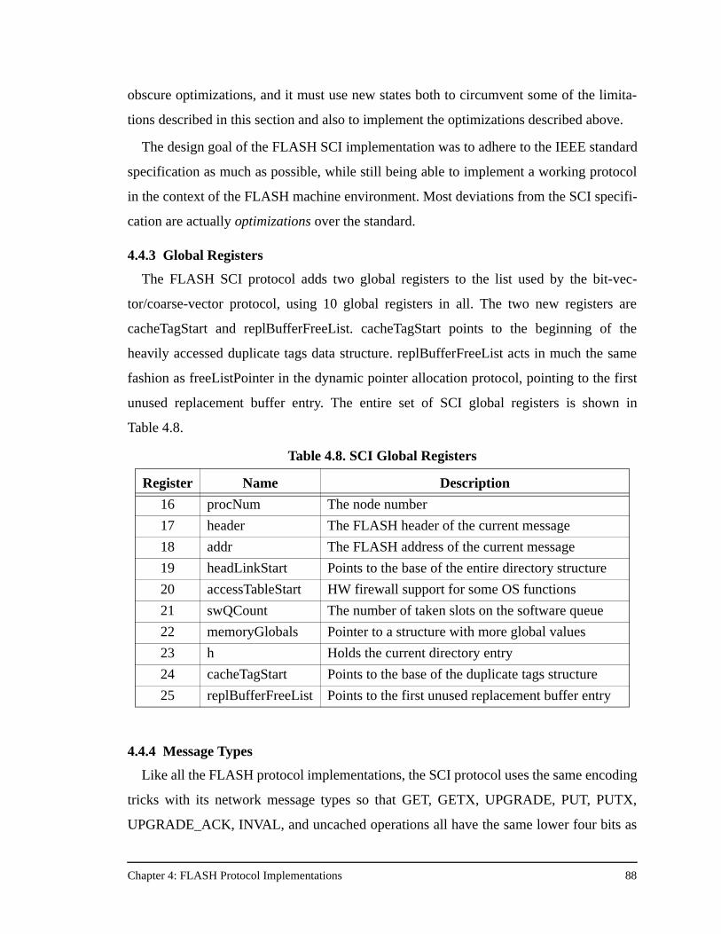
Chapter 4: FLASH Protocol Implementations 88
obscure optimizations, and it must use new states both to circumvent some of the limita-
tions described in this section and also to implement the optimizations described above.
The design goal of the FLASH SCI implementation was to adhere to the IEEE standard
specification as much as possible, while still being able to implement a working protocol
in the context of the FLASH machine environment. Most deviations from the SCI specifi-
cation are actually optimizations over the standard.
4.4.3 Global Registers
The FLASH SCI protocol adds two global registers to the list used by the bit-vec-
tor/coarse-vector protocol, using 10 global registers in all. The two new registers are
cacheTagStart and replBufferFreeList. cacheTagStart points to the beginning of the
heavily accessed duplicate tags data structure. replBufferFreeList acts in much the same
fashion as freeListPointer in the dynamic pointer allocation protocol, pointing to the first
unused replacement buffer entry. The entire set of SCI global registers is shown in
Table 4.8.
4.4.4 Message Types
Like all the FLASH protocol implementations, the SCI protocol uses the same encoding
tricks with its network message types so that GET, GETX, UPGRADE, PUT, PUTX,
UPGRADE_ACK, INVAL, and uncached operations all have the same lower four bits as
Table 4.8. SCI Global Registers
Register Name Description
16 procNum The node number
17 header The FLASH header of the current message
18 addr The FLASH address of the current message
19 headLinkStart Points to the base of the entire directory structure
20 accessTableStart HW firewall support for some OS functions
21 swQCount The number of taken slots on the software queue
22 memoryGlobals Pointer to a structure with more global values
23 h Holds the current directory entry
24 cacheTagStart Points to the base of the duplicate tags structure
25 replBufferFreeList Points to the first unused replacement buffer entry

Chapter 4: FLASH Protocol Implementations 89
Table 4.9. SCI Message Types and Lane Assignment for Cacheable Operations
Message Type Encoding LaneMSG_WB 0x00 Request
MSG_PASS_HEAD 0x01 Request
MSG_UPGRADE_DELAYED 0x03 Request
MSG_INVAL_DELAYED PI_DP_INVAL_REQ (0x04) Request
MSG_INVAL_DELAYED_UPGRADE 0x84 Request
MSG_GET PI_DP_GET_REQ (0x06) Request
MSG_GETX_DELAYED PI_DP_GETX_REQ (0x07) Request
MSG_UPGRADE_ACK_DELAYED PI_DP_ACK_RPLY (0x08) Reply
MSG_NAK PI_DP_NAK_RPLY (0x0a) Reply
MSG_PUT 0x0c Reply
MSG_PUT_ONLY_FRESH PI_DP_PUT_RPLY (0x0d) Reply
MSG_INVAL_ACK_DELAYED 0x0e Reply
MSG_INVAL_ACK_DELAYED_UPGRADE 0x8e Reply
MSG_PUTX_ONLY_DIRTY PI_DP_PUTX_RPLY (0x0f) Reply
MSG_PUTX 0x2f Reply
MSG_FORW_GET 0x11 Request
MSG_FORW_GET_IO 0x39 Request
MSG_MEMORY_GET 0x14 Request
MSG_MEMORY_GETX 0x15 Request
MSG_BACK_PUT 0x16 Reply
MSG_FORW_GETX 0x17 Request
MSG_FORW_GETX_IO 0x87 Request
MSG_PASS_HEAD_ACK 0x18 Reply
MSG_NAK_GETX 0x1a Reply
MSG_NAK_GETX_IO 0x8a Reply
MSG_SWB 0x1b Request
MSG_BACK_PUT_SWB 0x1c Reply
MSG_BACK_PUTX 0x1f Reply
MSG_NAK_GET 0x23 Reply
MSG_NAK_GET_IO 0x83 Reply
MSG_NAK_UPGRADE_GETX 0x25 Reply
MSG_NAK_UPGRADE 0x26 Reply
MSG_FORW_UPGRADE 0x28 Request
MSG_NOTIFY 0x29 Request
MSG_REPLACE_NOTIFY 0x33 Request
MSG_NAK_REPLACE_NOTIFY 0x35 Reply
MSG_DEC_SWQ_COUNT 0x37 Reply
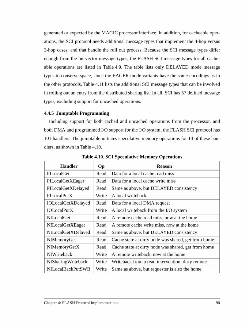
Chapter 4: FLASH Protocol Implementations 90
generated or expected by the MAGIC processor interface. In addition, for cacheable oper-
ations, the SCI protocol needs additional message types that implement the 4-hop versus
3-hop cases, and that handle the roll out process. Because the SCI message types differ
enough from the bit-vector message types, the FLASH SCI message types for all cache-
able operations are listed in Table 4.9. The table lists only DELAYED mode message
types to conserve space, since the EAGER mode variants have the same encodings as in
the other protocols. Table 4.11 lists the additional SCI message types that can be involved
in rolling out an entry from the distributed sharing list. In all, SCI has 57 defined message
types, excluding support for uncached operations.
4.4.5 Jumptable Programming
Including support for both cached and uncached operations from the processor, and
both DMA and programmed I/O support for the I/O system, the FLASH SCI protocol has
101 handlers. The jumptable initiates speculative memory operations for 14 of these han-
dlers, as shown in Table 4.10.
Table 4.10. SCI Speculative Memory Operations
Handler Op Reason
PILocalGet Read Data for a local cache read miss
PILocalGetXEager Read Data for a local cache write miss
PILocalGetXDelayed Read Same as above, but DELAYED consistency
PILocalPutX Write A local writeback
IOLocalGetXDelayed Read Data for a local DMA request
IOLocalPutX Write A local writeback from the I/O system
NILocalGet Read A remote cache read miss, now at the home
NILocalGetXEager Read A remote cache write miss, now at the home
NILocalGetXDelayed Read Same as above, but DELAYED consistency
NIMemoryGet Read Cache state at dirty node was shared, get from home
NIMemoryGetX Read Cache state at dirty node was shared, get from home
NIWriteback Write A remote writeback, now at the home
NISharingWriteback Write Writeback from a read intervention, dirty remote
NILocalBackPutSWB Write Same as above, but requester is also the home
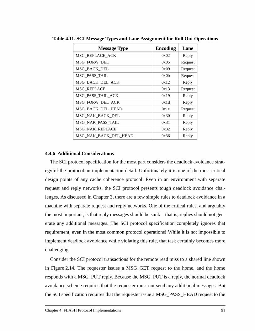
Chapter 4: FLASH Protocol Implementations 91
4.4.6 Additional Considerations
The SCI protocol specification for the most part considers the deadlock avoidance strat-
egy of the protocol an implementation detail. Unfortunately it is one of the most critical
design points of any cache coherence protocol. Even in an environment with separate
request and reply networks, the SCI protocol presents tough deadlock avoidance chal-
lenges. As discussed in Chapter 3, there are a few simple rules to deadlock avoidance in a
machine with separate request and reply networks. One of the critical rules, and arguably
the most important, is that reply messages should be sunk—that is, replies should not gen-
erate any additional messages. The SCI protocol specification completely ignores that
requirement, even in the most common protocol operations! While it is not impossible to
implement deadlock avoidance while violating this rule, that task certainly becomes more
challenging.
Consider the SCI protocol transactions for the remote read miss to a shared line shown
in Figure 2.14. The requester issues a MSG_GET request to the home, and the home
responds with a MSG_PUT reply. Because the MSG_PUT is a reply, the normal deadlock
avoidance scheme requires that the requester must not send any additional messages. But
the SCI specification requires that the requester issue a MSG_PASS_HEAD request to the
Table 4.11. SCI Message Types and Lane Assignment for Roll Out Operations
Message Type Encoding LaneMSG_REPLACE_ACK 0x02 Reply
MSG_FORW_DEL 0x05 Request
MSG_BACK_DEL 0x09 Request
MSG_PASS_TAIL 0x0b Request
MSG_BACK_DEL_ACK 0x12 Reply
MSG_REPLACE 0x13 Request
MSG_PASS_TAIL_ACK 0x19 Reply
MSG_FORW_DEL_ACK 0x1d Reply
MSG_BACK_DEL_HEAD 0x1e Request
MSG_NAK_BACK_DEL 0x30 Reply
MSG_NAK_PASS_TAIL 0x31 Reply
MSG_NAK_REPLACE 0x32 Reply
MSG_NAK_BACK_DEL_HEAD 0x36 Reply
Chapter 4: FLASH Protocol Implementations 92
old head of the sharing list, which then replies with an acknowledgment. From the discus-
sion of the inbox in Chapter 3, it is not guaranteed that incoming replies will find outgoing
request queue space available. This, in turn, requires that the protocol processor must have
some pre-reserved space to set this transaction aside, since simply waiting for outgoing
request queue space to become available can deadlock the machine. The FLASH solution
to this problem is to use the software queue. The problem then becomes one of ensuring
that space is available on the software queue. Checking for existing software queue space
would need to be done at the beginning of every transaction when the cache miss is first
issued at the requester, and adding such checks would impose an unnecessary latency pen-
alty on common protocol transactions. Instead, the FLASH implementation pre-reserves
software queue space specifically for these transactions at boot time. The software queue
count register is not initialized to 0, but to 4, the number of outstanding references allow-
able from each processor. Even though those slots may never be used, they are marked as
such so that they are always available to handle the deadlock avoidance strategy problems
caused by the SCI protocol specification.
Another deadlock avoidance requirement is that incoming requests can send additional
outgoing requests only after first checking for outgoing request network queue space. If no
space is available, the protocol must convert the incoming request into a reply, usually in
the form of a NAK. The astute reader may have noted that the FLASH SCI invalidation
optimization can potentially violate this deadlock avoidance requirement since the invali-
dation request in turn sends another invalidation request to the next node in the distributed
sharing list. The FLASH solution is to have each node check for outgoing queue space,
and if none exists, to send an invalidation acknowledgment reply back to the writer,
encoded with the identity of the next sharer in the list yet to be invalidated. At that point it
is up to the writer to continue invalidating the list. The writer is confronted with the prob-
lem above of having to convert a reply (the invalidation acknowledgment) into a request
(the next invalidation). If no outgoing request queue space is available the writer takes
advantage of the same pre-allocated software queue space guarantee described above to
set aside the transaction for future processing, completing the deadlock avoidance strategy
for this scenario.
Chapter 4: FLASH Protocol Implementations 93
Finally, the issue of increased protocol processor occupancy stemming from the man-
agement of the duplicate tags structure is at the core of the SCI results presented in Chap-
ter 6. Interestingly, the occupancy news for SCI is not all bad. Specifically, SCI only
occurs large occupancies at the requester (for the PI handlers). These are the handlers that
manipulate the duplicate tags data structure. The protocol processor occupancy at the
home node in SCI is actually comparable to the previous protocols and often less than the
COMA protocol, described next. The handlers executed at the home have both low
latency and low occupancy. This, combined with the fact that on retries the SCI protocol
does not ask the home node but instead asks the node in front of it in the distributed linked
list, helps distribute the message traffic more evenly throughout the machine and can
improve overall performance when there is significant hot-spotting in the memory system
of large machines.
4.5 FLASH COMA Implementation
The FLASH COMA protocol is a full-featured COMA-F protocol that provides both
hardware migration and replication of cache lines without requiring programmer interven-
tion. The FLASH COMA protocol uses the same directory organization as the dynamic
pointer allocation protocol—a linked list of sharers maintained at the home for each cache
line. The COMA protocol allocates an additional tag field in the directory header so that
the local main memory may be used as the COMA attraction memory (AM). To make
room for the tag field, some of the entries in the directory header are changed or shortened
from those in the dynamic pointer allocation directory header. The directory header for the
FLASH COMA protocol is shown in Figure 4.8 and each field is described below:
• HeadLink is the pointer to the next element in the linked list of sharers. It points to an element from the pointer/link store.
• Invalidate is set if the line to be invalidated does not yet reside in the attraction memory. If the line arrives from a non-master node and Invalidate is set, the line is not placed in the attraction memory.
• Reclaim is set if the cache line is currently undergoing pointer reclamation. Pointer reclamation was discussed in Section 4.3.4.
• Amstat is the state of the line currently in the attraction memory at this location. The possible attraction memory states are described below.
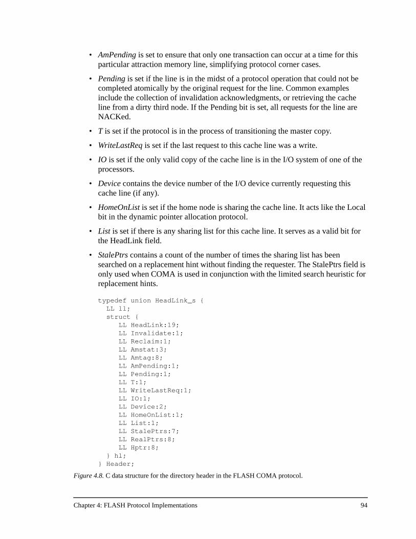
Chapter 4: FLASH Protocol Implementations 94
• AmPending is set to ensure that only one transaction can occur at a time for this particular attraction memory line, simplifying protocol corner cases.
• Pending is set if the line is in the midst of a protocol operation that could not be completed atomically by the original request for the line. Common examples include the collection of invalidation acknowledgments, or retrieving the cache line from a dirty third node. If the Pending bit is set, all requests for the line are NACKed.
• T is set if the protocol is in the process of transitioning the master copy.
• WriteLastReq is set if the last request to this cache line was a write.
• IO is set if the only valid copy of the cache line is in the I/O system of one of the processors.
• Device contains the device number of the I/O device currently requesting this cache line (if any).
• HomeOnList is set if the home node is sharing the cache line. It acts like the Local bit in the dynamic pointer allocation protocol.
• List is set if there is any sharing list for this cache line. It serves as a valid bit for the HeadLink field.
• StalePtrs contains a count of the number of times the sharing list has been searched on a replacement hint without finding the requester. The StalePtrs field is only used when COMA is used in conjunction with the limited search heuristic for replacement hints.
typedef union HeadLink_s { LL ll;
struct { LL HeadLink:19;
LL Invalidate:1; LL Reclaim:1;
LL Amstat:3; LL Amtag:8; LL AmPending:1; LL Pending:1; LL T:1; LL WriteLastReq:1; LL IO:1; LL Device:2; LL HomeOnList:1; LL List:1; LL StalePtrs:7; LL RealPtrs:8;
LL Hptr:8; } hl; } Header;
Figure 4.8. C data structure for the directory header in the FLASH COMA protocol.
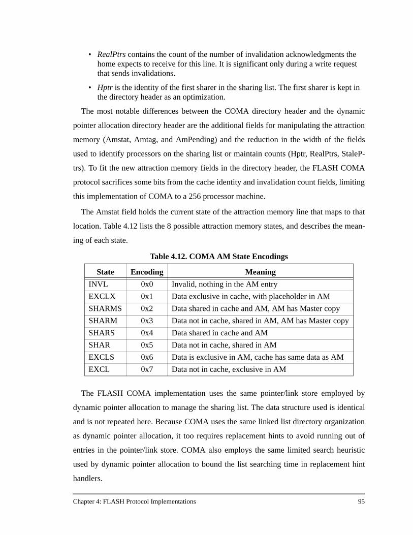
Chapter 4: FLASH Protocol Implementations 95
• RealPtrs contains the count of the number of invalidation acknowledgments the home expects to receive for this line. It is significant only during a write request that sends invalidations.
• Hptr is the identity of the first sharer in the sharing list. The first sharer is kept in the directory header as an optimization.
The most notable differences between the COMA directory header and the dynamic
pointer allocation directory header are the additional fields for manipulating the attraction
memory (Amstat, Amtag, and AmPending) and the reduction in the width of the fields
used to identify processors on the sharing list or maintain counts (Hptr, RealPtrs, StaleP-
trs). To fit the new attraction memory fields in the directory header, the FLASH COMA
protocol sacrifices some bits from the cache identity and invalidation count fields, limiting
this implementation of COMA to a 256 processor machine.
The Amstat field holds the current state of the attraction memory line that maps to that
location. Table 4.12 lists the 8 possible attraction memory states, and describes the mean-
ing of each state.
The FLASH COMA implementation uses the same pointer/link store employed by
dynamic pointer allocation to manage the sharing list. The data structure used is identical
and is not repeated here. Because COMA uses the same linked list directory organization
as dynamic pointer allocation, it too requires replacement hints to avoid running out of
entries in the pointer/link store. COMA also employs the same limited search heuristic
used by dynamic pointer allocation to bound the list searching time in replacement hint
handlers.
Table 4.12. COMA AM State Encodings
State Encoding Meaning
INVL 0x0 Invalid, nothing in the AM entry
EXCLX 0x1 Data exclusive in cache, with placeholder in AM
SHARMS 0x2 Data shared in cache and AM, AM has Master copy
SHARM 0x3 Data not in cache, shared in AM, AM has Master copy
SHARS 0x4 Data shared in cache and AM
SHAR 0x5 Data not in cache, shared in AM
EXCLS 0x6 Data is exclusive in AM, cache has same data as AM
EXCL 0x7 Data not in cache, exclusive in AM
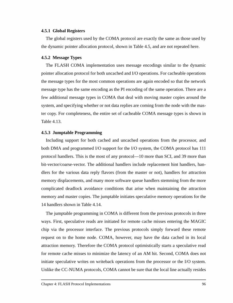
Chapter 4: FLASH Protocol Implementations 96
4.5.1 Global Registers
The global registers used by the COMA protocol are exactly the same as those used by
the dynamic pointer allocation protocol, shown in Table 4.5, and are not repeated here.
4.5.2 Message Types
The FLASH COMA implementation uses message encodings similar to the dynamic
pointer allocation protocol for both uncached and I/O operations. For cacheable operations
the message types for the most common operations are again encoded so that the network
message type has the same encoding as the PI encoding of the same operation. There are a
few additional message types in COMA that deal with moving master copies around the
system, and specifying whether or not data replies are coming from the node with the mas-
ter copy. For completeness, the entire set of cacheable COMA message types is shown in
Table 4.13.
4.5.3 Jumptable Programming
Including support for both cached and uncached operations from the processor, and
both DMA and programmed I/O support for the I/O system, the COMA protocol has 111
protocol handlers. This is the most of any protocol—10 more than SCI, and 39 more than
bit-vector/coarse-vector. The additional handlers include replacement hint handlers, han-
dlers for the various data reply flavors (from the master or not), handlers for attraction
memory displacements, and many more software queue handlers stemming from the more
complicated deadlock avoidance conditions that arise when maintaining the attraction
memory and master copies. The jumptable initiates speculative memory operations for the
14 handlers shown in Table 4.14.
The jumptable programming in COMA is different from the previous protocols in three
ways. First, speculative reads are initiated for remote cache misses entering the MAGIC
chip via the processor interface. The previous protocols simply forward these remote
request on to the home node. COMA, however, may have the data cached in its local
attraction memory. Therefore the COMA protocol optimistically starts a speculative read
for remote cache misses to minimize the latency of an AM hit. Second, COMA does not
initiate speculative writes on writeback operations from the processor or the I/O system.
Unlike the CC-NUMA protocols, COMA cannot be sure that the local line actually resides
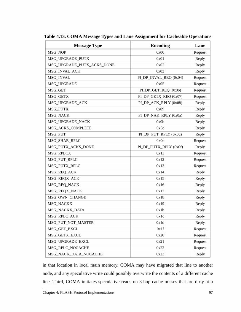
Chapter 4: FLASH Protocol Implementations 97
in that location in local main memory. COMA may have migrated that line to another
node, and any speculative write could possibly overwrite the contents of a different cache
line. Third, COMA initiates speculative reads on 3-hop cache misses that are dirty at a
Table 4.13. COMA Message Types and Lane Assignment for Cacheable Operations
Message Type Encoding LaneMSG_NOP 0x00 Request
MSG_UPGRADE_PUTX 0x01 Reply
MSG_UPGRADE_PUTX_ACKS_DONE 0x02 Reply
MSG_INVAL_ACK 0x03 Reply
MSG_INVAL PI_DP_INVAL_REQ (0x04) Request
MSG_UPGRADE 0x05 Request
MSG_GET PI_DP_GET_REQ (0x06) Request
MSG_GETX PI_DP_GETX_REQ (0x07) Request
MSG_UPGRADE_ACK PI_DP_ACK_RPLY (0x08) Reply
MSG_PUTX 0x09 Reply
MSG_NACK PI_DP_NAK_RPLY (0x0a) Reply
MSG_UPGRADE_NACK 0x0b Reply
MSG_ACKS_COMPLETE 0x0c Reply
MSG_PUT PI_DP_PUT_RPLY (0x0d) Reply
MSG_SHAR_RPLC 0x0e Request
MSG_PUTX_ACKS_DONE PI_DP_PUTX_RPLY (0x0f) Reply
MSG_RPLCX 0x11 Request
MSG_PUT_RPLC 0x12 Request
MSG_PUTX_RPLC 0x13 Request
MSG_REQ_ACK 0x14 Reply
MSG_REQX_ACK 0x15 Reply
MSG_REQ_NACK 0x16 Reply
MSG_REQX_NACK 0x17 Reply
MSG_OWN_CHANGE 0x18 Reply
MSG_NACKX 0x19 Reply
MSG_NACKX_DATA 0x1b Reply
MSG_RPLC_ACK 0x1c Reply
MSG_PUT_NOT_MASTER 0x1d Reply
MSG_GET_EXCL 0x1f Request
MSG_GETX_EXCL 0x20 Request
MSG_UPGRADE_EXCL 0x21 Request
MSG_RPLC_NOCACHE 0x22 Request
MSG_NACK_DATA_NOCACHE 0x23 Reply
Chapter 4: FLASH Protocol Implementations 98
remote node. The previous protocols do not perform any memory operations in these cases
because the data is dirty in the processor’s cache. But in COMA the AM may have the
desired data, and in the FLASH machine it is faster to retrieve the data from main memory
than it is from the processor cache. Consequently dirty remote handlers initiate speculative
reads and then check the AM state to ensure that the line can be transferred directly from
the AM. In some cases the AM does not have the latest copy of the data, and COMA has
to issue the processor intervention just as in the previous protocols.
4.5.4 Additional Considerations
The FLASH COMA implementation uses a direct-mapped attraction memory, even
though the processor cache is two-way set associative. As described in Section 2.6, this
simplifies the protocol and decreases its direct overhead since every cache miss needs
only to check one set of AM tags, and there is no need to keep LRU bits to run an AM
replacement algorithm. The downside of a direct-mapped attraction memory is that the
attraction memory needs to be much larger than the two-way set-associative processor
cache to avoid excessive AM conflicts. The FLASH COMA implementation solves this
Table 4.14. COMA Speculative Memory Operations
Handler Op Reason
PILocalGet Read Data for a local cache read miss
PILocalGetXEager Read Data for a local cache write miss
PILocalGetXDelayed Read Same as above, but DELAYED consistency
PIRemoteGet Read Data for a remote read miss, assume an AM hit!
PIRemoteGetXEager Read Data for a remote write miss, assume an AM hit!
PIRemoteGetXDelayed Read Same as above, but DELAYED consistency
IOLocalGetXDelayed Read Data for a local DMA request
NILocalGet Read A remote cache read miss, now at the home
NILocalGetXEager Read A remote cache write miss, now at the home
NILocalGetXDelayed Read Same as above, but DELAYED consistency
NIRemoteGet Read AM read at shared third node to satisfy a read miss
NIRemoteGetExcl Read Same as above, but at dirty third node
NIRemoteGetX Read AM read at shared third node to satisfy a write miss
NIRemoteGetXExcl Read Same as above, but at dirty third node
Chapter 4: FLASH Protocol Implementations 99
problem by allowing the processor to cache data that is not in the local attraction memory.
This, in turn, introduces extra complexity into the protocol that could have been avoided
by using a two-way set-associative attraction memory. A two-way set-associative attrac-
tion memory version of the COMA protocol is being developed at the time of this writing.
Further research will examine the tradeoffs of these two attraction memory organizations
on FLASH.
The FLASH COMA implementation operates best with large amounts of reserved
memory. As noted in Section 2.6, large amounts of reserved memory decrease the number
of AM displacements and therefore decrease the message overhead of the COMA proto-
col. In most of the simulations in Chapter 6, the reserved memory size is half of the local
main memory.
Finally, COMA’s higher latency in the remote processor interface handlers (shown in
Appendix A), and its higher occupancies for network interface handlers, both at the home
and on data replies (also shown in Appendix A), result in much high direct protocol over-
head than the previous protocols. Still, COMA may achieve better performance if the AM
hit rate is high enough. This trade-off is at the heart of the COMA results presented in
Chapter 6.
4.6 Protocol Summary
The previous sections have detailed each of the four FLASH protocol implementations
in this study. This section provides a table that summarizes some of the major characteris-
tics of each of the protocol implementations. Table 4.15 shows the number of handlers, the
approximate code size in bytes, whether the protocol has any data structures at the
requester, where invalidation acknowledgments are collected, whether replacement hints
are used, and whether the protocol keeps precise sharing information or not. Table 4.15 is
a useful reference when examining the results presented in Chapter 6.
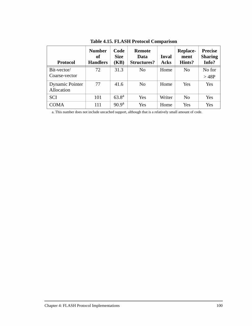
Chapter 4: FLASH Protocol Implementations 100
Table 4.15. FLASH Protocol Comparison
Protocol
Numberof
Handlers
CodeSize(KB)
RemoteData
Structures?InvalAcks
Replace-ment
Hints?
Precise Sharing
Info?
Bit-vector/Coarse-vector
72 31.3 No Home No No for
> 48P
Dynamic PointerAllocation
77 41.6 No Home Yes Yes
SCI 101 63.8a
a. This number does not include uncached support, although that is a relatively small amount of code.
Yes Writer No Yes
COMA 111 90.9a Yes Home Yes Yes
Chapter 5: Simulation Methodology 101
Chapter 5
Simulation Methodology
This chapter describes the simulation methodology used for the protocol comparisons
in this study. Since this research examines the scalability of cache coherence protocols to
128 processor machines, it must simulate applications that can scale to that number of pro-
cessors. The applications used, the multiple variants of the same application that were
simulated, and the problem sizes of the applications are discussed in Section 5.1. Section
5.2 describes the FLASH simulator, including both the processor model, and FlashLite,
the detailed memory system simulator for the Stanford FLASH multiprocessor. The chap-
ter concludes with a discussion of synchronization in Section 5.3.
5.1 Applications
To properly assess the scalability and robustness of cache coherence protocols it is nec-
essary to choose applications that scale well to large machine sizes. This currently trans-
lates to the realm of scientific applications but does not limit the applicability of this study.
As will be shown in Chapter 6, this study finds that protocol performance is important
over a reasonable spectrum of parallel applications, and that the optimal cache coherence
protocol can change with the application or the architectural parameters of the machine.
The applications are selected from the SPLASH-2 application suite [62]. In particular,
this study examines FFT, Ocean, Radix-Sort, LU, Barnes-Hut, and Water. All applications
except Barnes-Hut and Water use hand-inserted prefetches to reduce read miss
penalty [35]. To further improve scalability, the applications use software tree barriers
rather than traditional spin-lock barriers. For some applications this improved perfor-
mance by over 40% at large processor counts.
So that the applications achieve reasonable parallel performance, their problem sizes
are chosen to achieve a target minimum parallel efficiency at 128 processors. Parallel effi-
ciency is simply defined as speedup divided by the number of processors, and always var-
ies between 0 and 1. An application’s problem size is determined by choosing a target
minimum parallel efficiency of 60% for the best version of the application running the
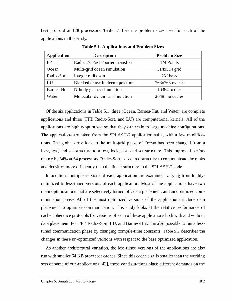
Chapter 5: Simulation Methodology 102
best protocol at 128 processors. Table 5.1 lists the problem sizes used for each of the
applications in this study.
Of the six applications in Table 5.1, three (Ocean, Barnes-Hut, and Water) are complete
applications and three (FFT, Radix-Sort, and LU) are computational kernels. All of the
applications are highly-optimized so that they can scale to large machine configurations.
The applications are taken from the SPLASH-2 application suite, with a few modifica-
tions. The global error lock in the multi-grid phase of Ocean has been changed from a
lock, test, and set structure to a test, lock, test, and set structure. This improved perfor-
mance by 34% at 64 processors. Radix-Sort uses a tree structure to communicate the ranks
and densities more efficiently than the linear structure in the SPLASH-2 code.
In addition, multiple versions of each application are examined, varying from highly-
optimized to less-tuned versions of each application. Most of the applications have two
main optimizations that are selectively turned off: data placement, and an optimized com-
munication phase. All of the most optimized versions of the applications include data
placement to optimize communication. This study looks at the relative performance of
cache coherence protocols for versions of each of these applications both with and without
data placement. For FFT, Radix-Sort, LU, and Barnes-Hut, it is also possible to run a less-
tuned communication phase by changing compile-time constants. Table 5.2 describes the
changes in these un-optimized versions with respect to the base optimized application.
As another architectural variation, the less-tuned versions of the applications are also
run with smaller 64 KB processor caches. Since this cache size is smaller than the working
sets of some of our applications [43], these configurations place different demands on the
Table 5.1. Applications and Problem Sizes
Application Description Problem Size
FFT Radix Fast Fourier Transform 1M Points
Ocean Multi-grid ocean simulation 514x514 grid
Radix-Sort Integer radix sort 2M keys
LU Blocked dense lu decomposition 768x768 matrix
Barnes-Hut N-body galaxy simulation 16384 bodies
Water Molecular dynamics simulation 2048 molecules
n
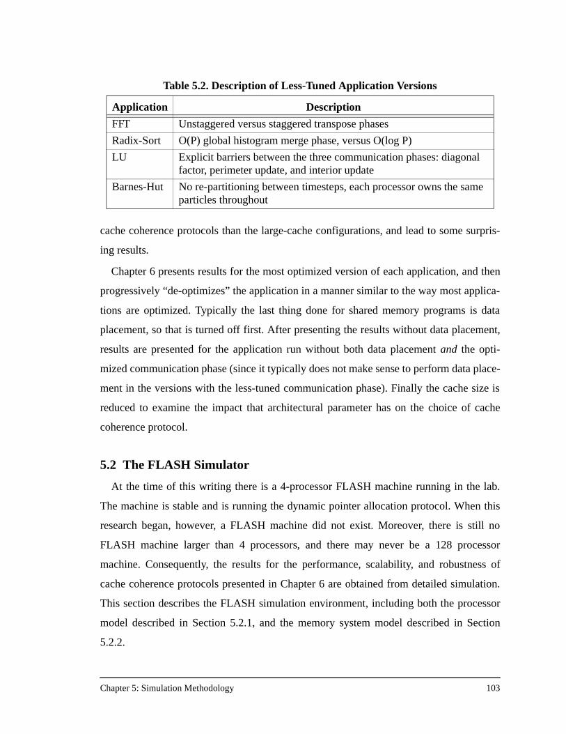
Chapter 5: Simulation Methodology 103
cache coherence protocols than the large-cache configurations, and lead to some surpris-
ing results.
Chapter 6 presents results for the most optimized version of each application, and then
progressively “de-optimizes” the application in a manner similar to the way most applica-
tions are optimized. Typically the last thing done for shared memory programs is data
placement, so that is turned off first. After presenting the results without data placement,
results are presented for the application run without both data placement and the opti-
mized communication phase (since it typically does not make sense to perform data place-
ment in the versions with the less-tuned communication phase). Finally the cache size is
reduced to examine the impact that architectural parameter has on the choice of cache
coherence protocol.
5.2 The FLASH Simulator
At the time of this writing there is a 4-processor FLASH machine running in the lab.
The machine is stable and is running the dynamic pointer allocation protocol. When this
research began, however, a FLASH machine did not exist. Moreover, there is still no
FLASH machine larger than 4 processors, and there may never be a 128 processor
machine. Consequently, the results for the performance, scalability, and robustness of
cache coherence protocols presented in Chapter 6 are obtained from detailed simulation.
This section describes the FLASH simulation environment, including both the processor
model described in Section 5.2.1, and the memory system model described in Section
5.2.2.
Table 5.2. Description of Less-Tuned Application Versions
Application Description
FFT Unstaggered versus staggered transpose phases
Radix-Sort O(P) global histogram merge phase, versus O(log P)
LU Explicit barriers between the three communication phases: diagonal factor, perimeter update, and interior update
Barnes-Hut No re-partitioning between timesteps, each processor owns the same particles throughout
Chapter 5: Simulation Methodology 104
5.2.1 Processor Model
Execution-driven simulation is used to produce the results in this study. The processor
simulator is Mipsy, an emulation-based simulator that is part of the SimOS suite [41] and
interfaces directly to FlashLite, our system-level simulator. Mipsy models the processor
and its caches, while FlashLite models everything from the processor bus downward.
In this study Mipsy simulates a single-issue 400 MHz processor with blocking reads
and non-blocking writes. Although the MIPS R10000 is a superscalar 200MHz processor,
the FLASH simulator is run with a single-issue processor model running 4 times faster
than the memory system rather than 2 times faster. This faster speed effectively sets the
average instructions per clock (IPC) to 2.0, approximating the complex behavior of the
R10000 and yielding a more realistic interval between memory references.
Mipsy controls both the first and second-level caches, which are parameterized to
match the R10000. The processor model has split first-level instruction and data caches of
32 KB each and a combined 1 MB, 2-way set-associative secondary cache with 128 byte
cache lines. There is a four entry miss handling table that holds all outstanding operations
including read misses, write misses, and prefetch operations. Though Mipsy has blocking
reads, this study uses prefetched versions of the applications to simulate a more aggressive
processor and memory system. Moreover, all the protocols operate in the relaxed EAGER
consistency mode that allows write data to be returned to the processor before all invalida-
tion acknowledgments have been collected [18]. To run in EAGER consistency mode, all
unlock operations use the R10000 sync instruction to ensure that all previous writes have
completed before the unlock operation. In addition, some flag writes in Barnes-Hut
needed to perform sync operations before the write to the flag.
5.2.2 FlashLite
FlashLite is the lightweight, threads-based, system-level simulator for the entire
FLASH machine. FlashLite uses Mipsy as its execution driven processor model [41] to
run real applications on a simulated FLASH machine. FlashLite sees every load and store
in the application and lets each memory reference travel through the FLASH node, giving
it the proper delay as it progresses. FlashLite allows easy modeling of functional units and
independent state machines that may interact in complex ways.
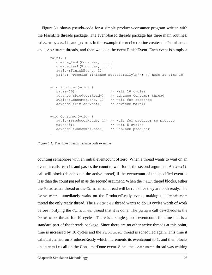
Chapter 5: Simulation Methodology 105
Figure 5.1 shows pseudo-code for a simple producer-consumer program written with
the FlashLite threads package. The event-based threads package has three main routines:
advance, await, and pause. In this example the main routine creates the Producer
and Consumer threads, and then waits on the event FinishEvent. Each event is simply a
counting semaphore with an initial eventcount of zero. When a thread wants to wait on an
event, it calls await and passes the count to wait for as the second argument. An await
call will block (de-schedule the active thread) if the eventcount of the specified event is
less than the count passed in as the second argument. When the main thread blocks, either
the Producer thread or the Consumer thread will be run since they are both ready. The
Consumer immediately waits on the ProducerReady event, making the Producer
thread the only ready thread. The Producer thread wants to do 10 cycles worth of work
before notifying the Consumer thread that it is done. The pause call de-schedules the
Producer thread for 10 cycles. There is a single global eventcount for time that is a
standard part of the threads package. Since there are no other active threads at this point,
time is increased by 10 cycles and the Producer thread is scheduled again. This time it
calls advance on ProducerReady which increments its eventcount to 1, and then blocks
on an await call on the ConsumerDone event. Since the Consumer thread was waiting
main() {create_task(Consumer, ...);create_task(Producer, ...);await(&FinishEvent, 1);printf(“Program finished successfully\n”); // here at time 15
}
void Producer(void) {pause(10); // wait 10 cycles advance(&ProducerReady); // advance Consumer threadawait(&ConsumerDone, 1); // wait for responseadvance(&FinishEvent); // advance main()
}
void Consumer(void) {await(&ProducerReady, 1); // wait for producer to producepause(5); // wait 5 cyclesadvance(&ConsumerDone); // unblock producer
}
Figure 5.1. FlashLite threads package code example
Chapter 5: Simulation Methodology 106
for the ProducerReady eventcount to be 1, it is marked as a ready thread at the point of the
advance. However, the Producer thread does not yield control until it calls await.
This is an important and powerful feature of the threads package—all actions inside a
thread are atomic until the thread calls either await or pause. Only on an await or a
pause will a thread yield control to another available thread. This makes it easier to write
critical sections and manage potentially complex thread interactions without giving up any
of the power of parallel threads. To finish our example, the Consumer thread then does 5
cycles worth of work and informs the Producer that it has finished. The Producer
wakes up and informs main that it is finished as well. Finally, the main routine wakes up
and ends gracefully at time 15.
Though the example above is purposefully simple, it is possible to model very complex
interactions quite easily with the threads package. To make it easy to model points of arbi-
tration (like scheduling a shared bus): the internal simulator clock runs at twice the clock
frequency of the system. It is easiest to think of this as running the simulation at half-cycle
granularity (or alternatively as being analogous to two-phase hardware design). All nor-
mal system threads call advance, await, or pause on integral cycle counts. If two
threads both want a shared bus on the same cycle, both may signify this with an advance
of some event. Normally an arbiter thread would wake up when this event is advanced and
that arbiter thread would run a scheduling policy to decide which of the two requesters
actually gets the bus. But the arbiter thread cannot run on integral cycle multiples, because
it needs to wait until all possible requests for the bus have been posted to make the proper
scheduling decision, and there is no implicit thread ordering within the same cycle. To
solve this problem, all arbitration threads run on half-cycle multiples. In this manner an
arbiter thread can now see everyone who made requests for the bus on the previous inte-
gral cycle, and make an informed decision as to who really gets the bus. After making the
decision, the arbiter thread waits a half-cycle to re-align itself to whole system clocks and
advances the eventcount of the winner.
Accuracy in the simulation environment is critical in assessing the performance differ-
ences of cache coherence protocols. This is especially true in the model of the communi-
cation controller, in this case the MAGIC chip and in particular, the protocol processor.
For example, rather than simulating the exact execution of the protocol code on the proto-
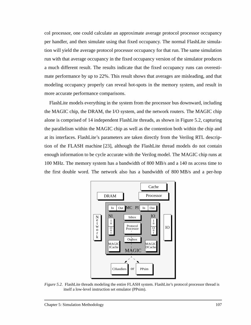
Chapter 5: Simulation Methodology 107
col processor, one could calculate an approximate average protocol processor occupancy
per handler, and then simulate using that fixed occupancy. The normal FlashLite simula-
tion will yield the average protocol processor occupancy for that run. The same simulation
run with that average occupancy in the fixed occupancy version of the simulator produces
a much different result. The results indicate that the fixed occupancy runs can overesti-
mate performance by up to 22%. This result shows that averages are misleading, and that
modeling occupancy properly can reveal hot-spots in the memory system, and result in
more accurate performance comparisons.
FlashLite models everything in the system from the processor bus downward, including
the MAGIC chip, the DRAM, the I/O system, and the network routers. The MAGIC chip
alone is comprised of 14 independent FlashLite threads, as shown in Figure 5.2, capturing
the parallelism within the MAGIC chip as well as the contention both within the chip and
at its interfaces. FlashLite’s parameters are taken directly from the Verilog RTL descrip-
tion of the FLASH machine [23], although the FlashLite thread models do not contain
enough information to be cycle accurate with the Verilog model. The MAGIC chip runs at
100 MHz. The memory system has a bandwidth of 800 MB/s and a 140 ns access time to
the first double word. The network also has a bandwidth of 800 MB/s and a per-hop
In OutPIIn Out MC
In
Out
In
Out
NI IO
Protocol
MAGIC
Processor
Cache
DRAM
IO
Network
Inbox
Outbox
ICache
CHandlers PPsim
MAGIC
or
MAGICDCache
Processor
Figure 5.2. FlashLite threads modeling the entire FLASH system. FlashLite’s protocol processor thread is itself a low-level instruction set emulator (PPsim).
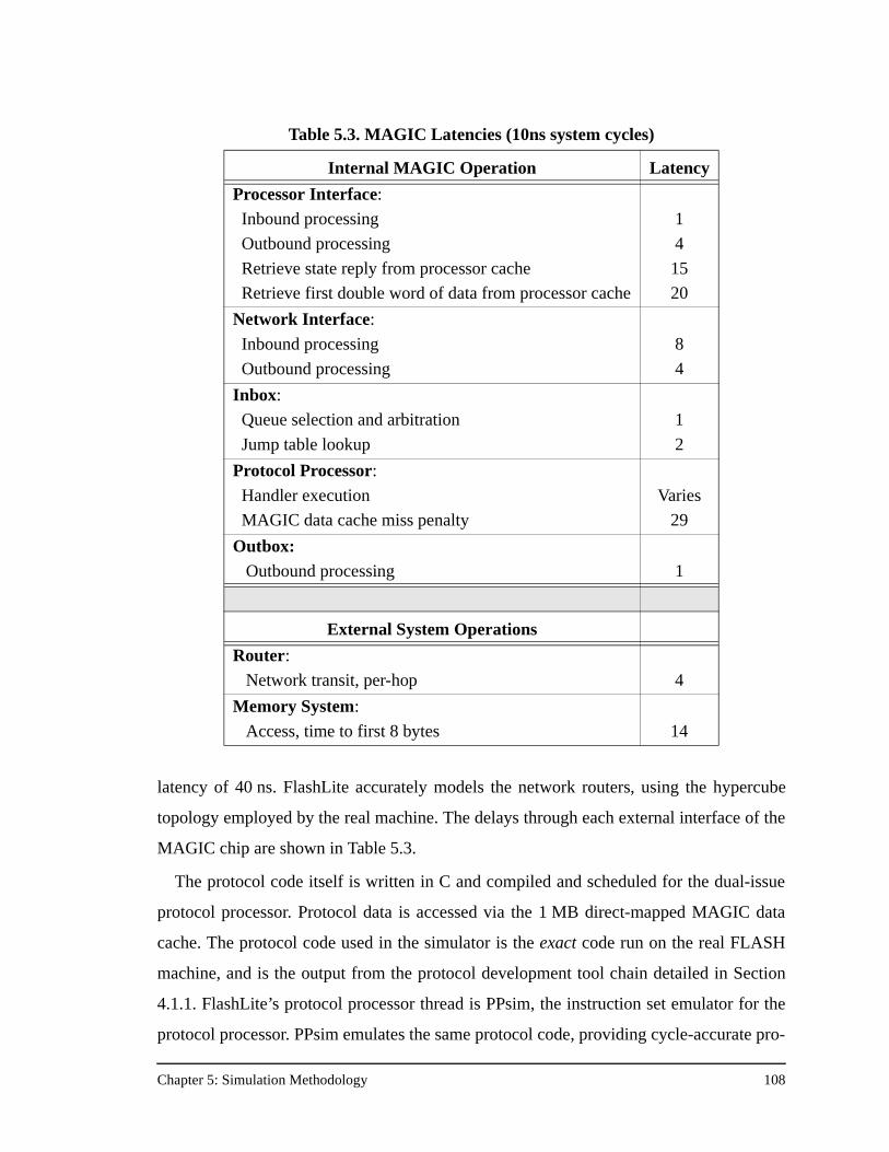
Chapter 5: Simulation Methodology 108
latency of 40 ns. FlashLite accurately models the network routers, using the hypercube
topology employed by the real machine. The delays through each external interface of the
MAGIC chip are shown in Table 5.3.
The protocol code itself is written in C and compiled and scheduled for the dual-issue
protocol processor. Protocol data is accessed via the 1 MB direct-mapped MAGIC data
cache. The protocol code used in the simulator is the exact code run on the real FLASH
machine, and is the output from the protocol development tool chain detailed in Section
4.1.1. FlashLite’s protocol processor thread is PPsim, the instruction set emulator for the
protocol processor. PPsim emulates the same protocol code, providing cycle-accurate pro-
Table 5.3. MAGIC Latencies (10ns system cycles)
Internal MAGIC Operation Latency
Processor Interface:
Inbound processing
Outbound processing
Retrieve state reply from processor cache
Retrieve first double word of data from processor cache
1
4
15
20
Network Interface:
Inbound processing
Outbound processing
8
4
Inbox:
Queue selection and arbitration
Jump table lookup
1
2
Protocol Processor:
Handler execution
MAGIC data cache miss penalty
Varies
29
Outbox:Outbound processing 1
External System Operations
Router:
Network transit, per-hop 4
Memory System:
Access, time to first 8 bytes 14
Chapter 5: Simulation Methodology 109
tocol processor timing information and precise MAGIC cache behavior. To factor out the
effect of protocol instruction cache misses, a perfect MAGIC instruction cache is simu-
lated in this study, rather than the normal 16 KB MAGIC instruction cache. Due to hard-
ware implementation constraints, the real MAGIC instruction cache is undersized. As the
protocol code sizes in Table 4.15 suggest, even a 32 KB instruction cache would capture
the important handlers sets in all four of the protocols. While SCI and COMA do have
larger code sizes than bit-vector and dynamic pointer allocation, the number of instruction
cache misses can be reduced with a more realistic instruction cache size and with more
aggressive instruction cache packing techniques [57][63].
5.3 Synchronization
The scientific applications in this study initially used LL/SC barriers when the applica-
tion required a barrier, but the simulations reproduced the well-known result that LL/SC
barriers are not scalable. As an alternative, the applications were re-coded to employ soft-
ware tree barriers. There is very little difference between LL/SC barriers and tree barriers
on 16 processor systems, but for larger machine sizes the tree barrier code is significantly
faster. For example, in Ocean the tree barrier code is 1.1 times faster on 32 processor sys-
tems, 1.3 times faster on 64 processor machines, and an eye-popping 2.9 times faster on
128 processor machines. The results presented in Chapter 6 use software tree barriers to
help the applications naturally scale to 128 processors. This enables the measurement of
the performance impact of the different cache coherence protocols on a FLASH machine
that is fundamentally operating well.
Aside from allowing multiple cache coherence protocols, the flexibility of the MAGIC
chip enables the implementation of efficient synchronization primitives and custom syn-
chronization protocols. Other work has focused on implementing tree barriers using only
MAGIC chips, and implementing a custom scalable lock protocol [22]. As that research
proceeded concurrently with this, the results presented here do not use the special MAGIC
synchronization primitives. Although MAGIC synchronization primitives would slightly
improve the performance of the most-optimized versions of the applications, their affect
on the less-optimized application versions is less clear. Many of those applications have
large read and write stall times which would not be affected by the new MAGIC synchro-
Chapter 5: Simulation Methodology 110
nization. However, some of the less-optimized applications so suffer from severe hot-spot-
ting during global synchronization, a condition which could be improved by using
MAGIC synchronization.
From the perspective of this research, it is not critical which scalable synchronization
methods are used as long as the machine is operating well for the most optimized applica-
tions. Either method of synchronization would still produce the results in the next chapter
that highlight the differences between the four cache coherence protocols as the machine
size scales, application characteristics change, or architectural parameters are varied.
Chapter 6: Results 111
Chapter 6
Results
This chapter presents the simulation results of the comparison of the performance, scal-
ability, and robustness of four DSM cache coherence protocols running on the Stanford
FLASH multiprocessor: bit-vector/coarse-vector, dynamic pointer allocation, SCI, and
COMA. Details of the protocols were outlined in Chapter 2 and Chapter 4, details of the
FLASH architecture that pertain to protocol development were discussed in Chapter 3,
and the simulation methodology used for these performance comparisons was described in
Chapter 5. Although this chapter does not discuss every simulation result in the study, the
results presented are representative of the entire set and show the range of performance
observed for each of the cache coherence protocols. The full table of results is given in
Appendix B.
Section 6.1 begins by re-stating the research questions explored in this study. Section
6.2 shows performance information for both FLASH and commercially available DSM
machines, making the point that FLASH is performing well, and the cache coherence pro-
tocols implemented in software on FLASH’s protocol processor can achieve “hardware-
like” performance. Next, Section 6.3 details the differences in direct protocol overhead for
the four cache coherence protocols. Section 6.4 then discusses the relative message over-
head of the four protocols. These two factors play a significant role in the performance
results presented next. Section 6.5 presents the detailed simulation results for each of the
applications and their variants described in Section 5.1. Finally, Section 6.6 summarizes
the main findings of this chapter.
6.1 Key Questions Revisited
The FLASH multiprocessor provides the vehicle for the comparative performance eval-
uation of DSM cache coherence protocols. Using the FLASH implementation of the pro-
tocols, it is possible to quantitatively compare the four protocols and find the answers to
the research questions first proposed in Section 2.7. For convenience, those question are
repeated here:
Chapter 6: Results 112
• Is there a single optimal protocol for all applications?
• Does the optimal protocol vary with machine size?
• Does the optimal protocol change with application optimization level?
• Does the optimal protocol change with the cache size?
• Can a single architecture achieve robust performance across a wide range of machine sizes and application characteristics?
6.2 DSM Latencies
The Stanford FLASH multiprocessor implements its cache coherence protocols in soft-
ware, but it is not a software cache-coherent machine. Rather, FLASH is a hardware
cache-coherent machine with a flexible protocol engine. Sequent takes a similar approach
in the design of their SCI Cache Link Interface Controller (SCLIC) for the NUMA-Q
machine [33]. The SCLIC contains a pipelined protocol engine that can operate on one of
twelve independent hardware tasks and receives instructions from an on-chip 16 KB pro-
gram store. Although the SCLIC is programmable, it is not as flexible as MAGIC's proto-
col processor as it supports only single cache coherence protocol and has limits on the
number of outstanding messages per node.
These architectures do not implement the coherence protocols on the main compute
processor as in software cache-coherent machines. Instead, like all hardware cache-coher-
ent machines, they have node controllers that handle communication both within and
between nodes. FLASH's node controller, MAGIC, is carefully designed to keep the data
transfer paths in hardware and only implement the control logic in software. Thus FLASH
maintains several advantages of software cache-coherent machines, but operates at the
speed of hardware cache-coherent machines.
In fact, as Table 6.1 shows, FLASH operates faster than many other hardware cache-
coherent DSM machines. Table 6.1 shows read latencies in nanoseconds for FLASH and
commercially available DSM machines at the time of this writing. The table shows three
read times: a local cache read miss, a remote read miss where the data is supplied by the
home node, and a remote read miss where the data must be supplied by a dirty third node.
The latter two cases involve network traversals where the average number of hops is
assumed for a 32 processor machine, except in the case of the HAL machine which
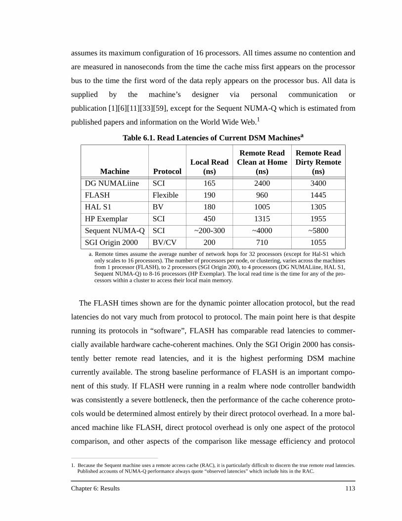
Chapter 6: Results 113
assumes its maximum configuration of 16 processors. All times assume no contention and
are measured in nanoseconds from the time the cache miss first appears on the processor
bus to the time the first word of the data reply appears on the processor bus. All data is
supplied by the machine’s designer via personal communication or
publication [1][6][11][33][59], except for the Sequent NUMA-Q which is estimated from
published papers and information on the World Wide Web.1
The FLASH times shown are for the dynamic pointer allocation protocol, but the read
latencies do not vary much from protocol to protocol. The main point here is that despite
running its protocols in “software”, FLASH has comparable read latencies to commer-
cially available hardware cache-coherent machines. Only the SGI Origin 2000 has consis-
tently better remote read latencies, and it is the highest performing DSM machine
currently available. The strong baseline performance of FLASH is an important compo-
nent of this study. If FLASH were running in a realm where node controller bandwidth
was consistently a severe bottleneck, then the performance of the cache coherence proto-
cols would be determined almost entirely by their direct protocol overhead. In a more bal-
anced machine like FLASH, direct protocol overhead is only one aspect of the protocol
comparison, and other aspects of the comparison like message efficiency and protocol
1. Because the Sequent machine uses a remote access cache (RAC), it is particularly difficult to discern the true remote read latencies.Published accounts of NUMA-Q performance always quote “observed latencies” which include hits in the RAC.
Table 6.1. Read Latencies of Current DSM Machinesa
Machine ProtocolLocal Read
(ns)
Remote ReadClean at Home
(ns)
Remote ReadDirty Remote
(ns)
DG NUMALiine SCI 165 2400 3400
FLASH Flexible 190 960 1445
HAL S1 BV 180 1005 1305
HP Exemplar SCI 450 1315 1955
Sequent NUMA-Q SCI ~200-300 ~4000 ~5800
SGI Origin 2000 BV/CV 200 710 1055a. Remote times assume the average number of network hops for 32 processors (except for Hal-S1 which
only scales to 16 processors). The number of processors per node, or clustering, varies across the machinesfrom 1 processor (FLASH), to 2 processors (SGI Origin 200), to 4 processors (DG NUMALiine, HAL S1,Sequent NUMA-Q) to 8-16 processors (HP Exemplar). The local read time is the time for any of the pro-cessors within a cluster to access their local main memory.
Chapter 6: Results 114
scalability features come into play. The results in Section 6.5 will show significant perfor-
mance differences between the cache coherence protocols due to all of these protocol
characteristics.
6.3 Direct Protocol Overhead
To help understand the performance results presented in Section 6.5, it is first useful to
examine what happens on a cache read miss under each protocol. Figure 6.1 shows the
protocol processor latencies and occupancies for two common read miss cases: a local
read miss, and a remote read miss satisfied by the home node. Although there are other
read miss cases, the ones shown in Figure 6.1 are representative and bring out the salient
points in this discussion. The remote read miss in Figure 6.1 is separated into the portion
of the request handled at the requester on the way to the home (the second group of bars),
the portion of the miss handled by the home itself (the third group), and the reply portion
of the miss handled back at the requester (the fourth group). Latency is defined as the time
from the beginning of the miss handler until the time the protocol processor sends the out-
going request or reply. Occupancy is defined as the time from the beginning of the handler
to the end. Latency and occupancy are often different because each protocol strives to
send the outgoing message as soon as possible to minimize overall request latency, and
finishes up its bookkeeping operations after the message is sent.
Note also that the latency in Figure 6.1 is not the overall end-to-end miss latency, but
rather just the handler component (path length) of the miss. The overall miss latency also
includes fixed MAGIC interface delays, the memory access (if required, and the memory
latency is the critical path rather than the handler latency), and in the case of a remote
miss, the network traversal itself. In fact, in FLASH, local read miss handlers with laten-
cies of 9 or 10 protocol processor cycles result in precisely the same overall local read
miss latency because performance is limited by the memory access operating in parallel
with the miss handler and not the handler component of the miss.
Figure 6.1 shows that the latency for the local read miss case is about the same in all the
protocols. SCI has the highest latency because as part of its deadlock avoidance scheme it
must check for space in the replacement buffer before allowing the request to proceed.
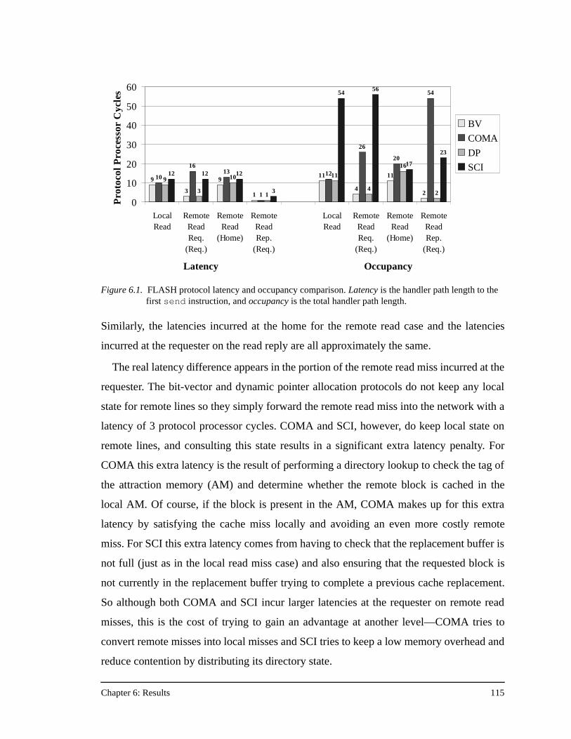
Chapter 6: Results 115
Similarly, the latencies incurred at the home for the remote read case and the latencies
incurred at the requester on the read reply are all approximately the same.
The real latency difference appears in the portion of the remote read miss incurred at the
requester. The bit-vector and dynamic pointer allocation protocols do not keep any local
state for remote lines so they simply forward the remote read miss into the network with a
latency of 3 protocol processor cycles. COMA and SCI, however, do keep local state on
remote lines, and consulting this state results in a significant extra latency penalty. For
COMA this extra latency is the result of performing a directory lookup to check the tag of
the attraction memory (AM) and determine whether the remote block is cached in the
local AM. Of course, if the block is present in the AM, COMA makes up for this extra
latency by satisfying the cache miss locally and avoiding an even more costly remote
miss. For SCI this extra latency comes from having to check that the replacement buffer is
not full (just as in the local read miss case) and also ensuring that the requested block is
not currently in the replacement buffer trying to complete a previous cache replacement.
So although both COMA and SCI incur larger latencies at the requester on remote read
misses, this is the cost of trying to gain an advantage at another level—COMA tries to
convert remote misses into local misses and SCI tries to keep a low memory overhead and
reduce contention by distributing its directory state.
Figure 6.1. FLASH protocol latency and occupancy comparison. Latency is the handler path length to the first send instruction, and occupancy is the total handler path length.
9
3
9
1
11
4
11
2
10
1613
1
12
26
20
54
9
3
10
1
11
4
16
2
12 12 12
3
5456
17
23
0
10
20
30
40
50
60
LocalRead
RemoteReadReq.
(Req.)
RemoteRead
(Home)
RemoteReadRep.
(Req.)
LocalRead
RemoteReadReq.
(Req.)
RemoteRead
(Home)
RemoteReadRep.
(Req.)
Latency Occupancy
Pro
toco
l Pro
cess
or C
ycle
sBV
COMA
DP
SCI
Chapter 6: Results 116
The latency differences between the protocols are small compared to the occupancy dif-
ferences shown on the right-hand side of Figure 6.1. In the local read case, bit-vector,
COMA, and dynamic pointer allocation have only marginally larger occupancies than
their corresponding latencies. But SCI incurs almost five times the occupancy of the other
protocols on a local read miss. The same holds for the remote read case at the requester—
SCI again suffers a huge occupancy penalty. In addition, both SCI and COMA have much
larger occupancies than bit-vector and dynamic pointer allocation at the requester on the
read reply, although in this case COMA has the highest controller occupancy. But interest-
ingly, at the home node, SCI’s occupancy is near the occupancies of bit-vector and
dynamic pointer allocation and slightly less than COMA's occupancy of 20 protocol pro-
cessor cycles. The reasons behind the higher occupancies of SCI and COMA at the
requester are discussed in turn, below.
SCI’s high occupancy at the requester is due to its cache replacement algorithm. As dis-
cussed in Chapter 4, SCI does not use replacement hints, but instead maintains a set of
duplicate cache tags. On every cache miss, whether local or remote, SCI must roll out the
block that is being displaced from the cache by the current cache miss. After first handling
the current miss to keep its latency as low as possible, SCI begins the roll out of the old
block. During roll out SCI performs the following actions:
• extracts the cache “way” indication from the incoming message header
• reads the old tag information from the duplicate tags structure
• builds the new tag structure for the cache line being currently requested
• writes the new tag information into the duplicate tags structure
• converts the tag index of the line being rolled out into a full physical address
• checks the old tag state and begins a distributed replacement sequence
• hashes the old tag into the replacement buffer for future retrieval
All of this work adds up to the large occupancies incurred at the requester in the first
two cases in Figure 6.1. The 23 cycle occupancy at the requester on the reply stems from
the way SCI maintains its distributed linked list of sharing information. After the data is
returned to the processor, the requesting node must notify the old head of the sharing list
that it is now the new head, and the old head updates its backward pointer to the requester.
Chapter 6: Results 117
The process of looking up the duplicate tag information to check the cache state, and then
sending the change-of-head message accounts for the additional occupancy on the read
reply. The results in Section 6.5 will show that this high occupancy (particularly on
requests) is difficult to overcome at small processor counts, but at larger processor counts,
especially in the presence of hot-spotting, incurring occupancy at the requester rather than
the home can help balance the load in the memory system and result in lower synchroniza-
tion times and better overall performance.
COMA incurs 10 cycles of occupancy above and beyond its latency for the portion of a
remote read miss handled at the requesting node. Besides the normal update of its AM
data structures, COMA has to deal with the case of a conflict between the direct-mapped
AM and the 2-way set associative processor secondary cache, adding some additional
overhead to the handler. A COMA protocol with a 2-way set associative AM would not
incur this particular overhead, but it would have its own additional costs in both latency
and occupancy. For the remote read case at the home, COMA’s occupancy is only four
cycles more than that of dynamic pointer allocation. The extra occupancy stems from
COMA updating the master indication and a few extra state bits in the directory entry.
The largest controller occupancy for COMA, however, is incurred at the requester on
the read reply. COMA immediately sends the data to the processor cache, incurring only
one cycle of latency, but then it must check to see if any AM replacements need to be per-
formed, and if so, send off those messages. Because this is the case of a reply generating
additional requests, careful checks have to be made in terms of software queue space to
avoid deadlock. In addition, AM replacements may contain data. Since this handler is
already a read reply with data, the handler may need to allocate a new data buffer for the
AM replacement. Once the AM replacement is sent, the handler must then write the cur-
rent data reply into the proper spot in the AM. Although this particular case incurs high
occupancy in COMA, the good news is that it is not incurred at the home, and it occurs on
a reply that finishes a transaction, rather than a request which can be NAKed by the home
and retried many times, incurring large occupancy each time.
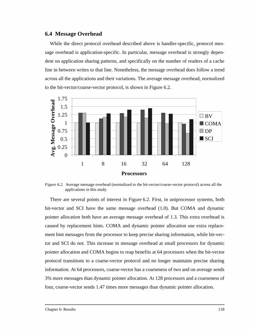
Chapter 6: Results 118
6.4 Message Overhead
While the direct protocol overhead described above is handler-specific, protocol mes-
sage overhead is application-specific. In particular, message overhead is strongly depen-
dent on application sharing patterns, and specifically on the number of readers of a cache
line in between writes to that line. Nonetheless, the message overhead does follow a trend
across all the applications and their variations. The average message overhead, normalized
to the bit-vector/coarse-vector protocol, is shown in Figure 6.2.
There are several points of interest in Figure 6.2. First, in uniprocessor systems, both
bit-vector and SCI have the same message overhead (1.0). But COMA and dynamic
pointer allocation both have an average message overhead of 1.3. This extra overhead is
caused by replacement hints. COMA and dynamic pointer allocation use extra replace-
ment hint messages from the processor to keep precise sharing information, while bit-vec-
tor and SCI do not. This increase in message overhead at small processors for dynamic
pointer allocation and COMA begins to reap benefits at 64 processors when the bit-vector
protocol transitions to a coarse-vector protocol and no longer maintains precise sharing
information. At 64 processors, coarse-vector has a coarseness of two and on average sends
3% more messages than dynamic pointer allocation. At 128 processors and a coarseness of
four, coarse-vector sends 1.47 times more messages than dynamic pointer allocation.
Figure 6.2. Average message overhead (normalized to the bit-vector/coarse-vector protocol) across all the applications in this study.
0
0.25
0.5
0.75
1
1.25
1.5
1.75
1 8 16 32 64 128
Processors
Avg
. Mes
sage
Ove
rhea
d
BVCOMADPSCI
Chapter 6: Results 119
COMA maintains about a 1.3 times average message overhead over bit-vector/coarse-
vector until the machine size reaches 128 processors. One of the main goals of the COMA
protocol is to reduce the number of remote read misses with respect to a NUMA protocol
like bit-vector. A by-product of this goal is a reduction in message count. The fact that
COMA’s message overhead remains higher than bit-vector/coarse-vector for all but the
largest machine sizes foreshadows somewhat the COMA results in Section 6.5. There is a
small dip in COMA’s message overhead at 8 processors where average message overhead
drops to 1.1 times the bit-vector protocol. Section 6.5.2.3 will show that COMA performs
best with small processor caches at small machine sizes. Its lower message overhead at 8
processors stems from that behavior.
SCI’s message overhead is always higher than the bit-vector/coarse-vector protocol.
This is not as damaging a statement as it is for COMA, which relies on a reduction in mes-
sage count. For scalable performance SCI is willing to tradeoff message efficiency for
scalability and improved memory efficiency. At small processor counts, SCI’s average
message overhead increases from 1.3 at 8 processors to 1.44 at 32 processors. Because
SCI maintains precise sharing information, its message overhead begins to drop as the
coarseness of the bit-vector/coarse-vector protocol increases.
Specific results for relative message overhead across the protocols will be given in each
application section in Section 6.5 where it is necessary to explain the performance differ-
ences between the protocols.
6.5 Application Performance
Most of the graphs in this section show normalized execution time versus the number of
processors, with the processor count varying from 1 to 128. For each processor count, the
application execution time under each of the four cache coherence protocols is normalized
to the execution time for the bit-vector/coarse-vector protocol for that processor count. In
other words, the bit-vector/coarse-vector bars always have a height of 1.0, and shorter bars
indicate better performance. Sections 6.5.1 through 6.5.6 present the results for each appli-
cation and their variations discussed in Section 5.1.
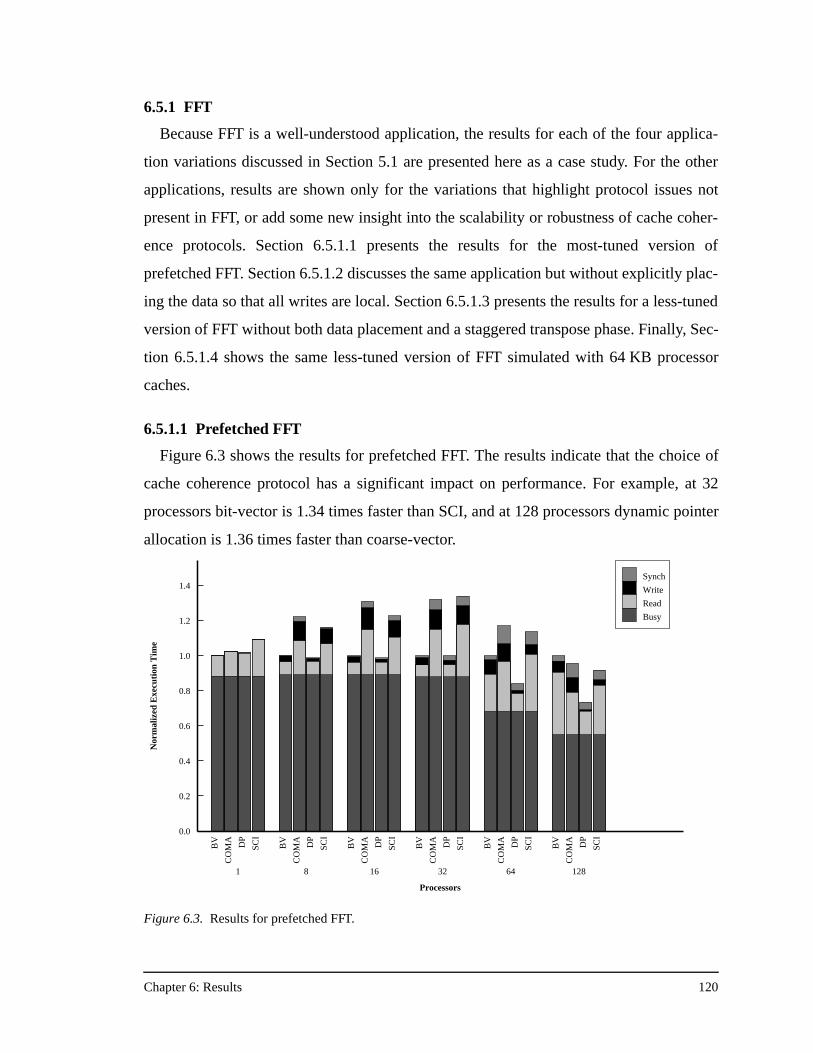
Chapter 6: Results 120
6.5.1 FFT
Because FFT is a well-understood application, the results for each of the four applica-
tion variations discussed in Section 5.1 are presented here as a case study. For the other
applications, results are shown only for the variations that highlight protocol issues not
present in FFT, or add some new insight into the scalability or robustness of cache coher-
ence protocols. Section 6.5.1.1 presents the results for the most-tuned version of
prefetched FFT. Section 6.5.1.2 discusses the same application but without explicitly plac-
ing the data so that all writes are local. Section 6.5.1.3 presents the results for a less-tuned
version of FFT without both data placement and a staggered transpose phase. Finally, Sec-
tion 6.5.1.4 shows the same less-tuned version of FFT simulated with 64 KB processor
caches.
6.5.1.1 Prefetched FFT
Figure 6.3 shows the results for prefetched FFT. The results indicate that the choice of
cache coherence protocol has a significant impact on performance. For example, at 32
processors bit-vector is 1.34 times faster than SCI, and at 128 processors dynamic pointer
allocation is 1.36 times faster than coarse-vector.
BV
CO
MA DP
SCI
1
BV
CO
MA DP
SCI
8
BV
CO
MA DP
SCI
16
BV
CO
MA DP
SCI
32
BV
CO
MA DP
SCI
64
BV
CO
MA DP
SCI
128
Processors
0.0
0.2
0.4
0.6
0.8
1.0
1.2
1.4
Nor
mal
ized
Exe
cuti
on T
ime
Synch
Write
Read
Busy
Figure 6.3. Results for prefetched FFT.
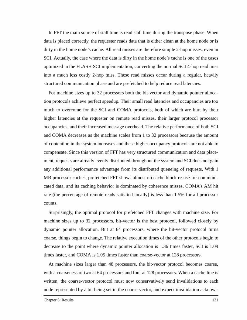
Chapter 6: Results 121
In FFT the main source of stall time is read stall time during the transpose phase. When
data is placed correctly, the requester reads data that is either clean at the home node or is
dirty in the home node’s cache. All read misses are therefore simple 2-hop misses, even in
SCI. Actually, the case where the data is dirty in the home node’s cache is one of the cases
optimized in the FLASH SCI implementation, converting the normal SCI 4-hop read miss
into a much less costly 2-hop miss. These read misses occur during a regular, heavily
structured communication phase and are prefetched to help reduce read latencies.
For machine sizes up to 32 processors both the bit-vector and dynamic pointer alloca-
tion protocols achieve perfect speedup. Their small read latencies and occupancies are too
much to overcome for the SCI and COMA protocols, both of which are hurt by their
higher latencies at the requester on remote read misses, their larger protocol processor
occupancies, and their increased message overhead. The relative performance of both SCI
and COMA decreases as the machine scales from 1 to 32 processors because the amount
of contention in the system increases and these higher occupancy protocols are not able to
compensate. Since this version of FFT has very structured communication and data place-
ment, requests are already evenly distributed throughout the system and SCI does not gain
any additional performance advantage from its distributed queueing of requests. With 1
MB processor caches, prefetched FFT shows almost no cache block re-use for communi-
cated data, and its caching behavior is dominated by coherence misses. COMA’s AM hit
rate (the percentage of remote reads satisfied locally) is less than 1.5% for all processor
counts.
Surprisingly, the optimal protocol for prefetched FFT changes with machine size. For
machine sizes up to 32 processors, bit-vector is the best protocol, followed closely by
dynamic pointer allocation. But at 64 processors, where the bit-vector protocol turns
coarse, things begin to change. The relative execution times of the other protocols begin to
decrease to the point where dynamic pointer allocation is 1.36 times faster, SCI is 1.09
times faster, and COMA is 1.05 times faster than coarse-vector at 128 processors.
At machine sizes larger than 48 processors, the bit-vector protocol becomes coarse,
with a coarseness of two at 64 processors and four at 128 processors. When a cache line is
written, the coarse-vector protocol must now conservatively send invalidations to each
node represented by a bit being set in the coarse-vector, and expect invalidation acknowl-
Chapter 6: Results 122
edgments from those nodes as well, regardless of whether or not that node is actually shar-
ing the cache line. Because coarse-vector is keeping imprecise sharing information, it
simply does not know the true sharing state of any individual processor.
The performance impact of this conservative sending of invalidations is at its peak in
FFT. FFT is structured such that any time a cache line is written during the transpose
phase, there is always exactly one sharer. This means that to maintain coherence, a proto-
col needs to send only one invalidation per write. Dynamic pointer allocation, SCI, and
COMA all maintain precise sharing information at all machine sizes, so they indeed send
only one invalidation per write for FFT. But the coarse-vector protocol sends a number of
invalidations equal to its coarseness—two at 64 processors and four at 128 processors.
These extra invalidations and invalidation acknowledgments result in significant message
overhead. Figure 6.4 shows the message overhead versus processor count for prefetched
FFT under each of the protocols.
Figure 6.4 brings to light two interesting points. First, COMA and dynamic pointer allo-
cation send 1.25 times the number of messages as bit-vector and SCI for a uniprocessor
machine! These extra messages are due solely to replacement hints. COMA and dynamic
pointer allocation use replacement hints, while bit-vector and SCI do not. Second, while
the bit-vector protocol sends the fewest messages for machine sizes between 1 and 32 pro-
cessors, it sends the most messages for any machine size larger than 32 processors. At 64
Figure 6.4. Relative protocol message overhead for prefetched FFT.
0
0.2
0.4
0.6
0.8
1
1.2
1.4
1.6
1.8
1 8 16 32 64 128
Processors
Mes
sage
Ove
rhea
d
BV
COMA
DP
SCI
Chapter 6: Results 123
processors coarse-vector sends 1.4 times more messages than dynamic pointer allocation,
and at 128 processors coarse-vector sends 2.78 times more messages than dynamic pointer
allocation. Even though the bit-vector/coarse-vector protocol handles each individual
message efficiently (with low direct protocol overhead), at large machine sizes there are
now simply too many messages to handle, and performance degrades relative to the other
protocols that are maintaining precise sharing information.
Note that while message overhead is the reason for the performance degradation of the
coarse-vector protocol, it is not the sole determinant of performance. At 128 processors
the bit-vector protocol sends 2.0 times more messages than COMA but COMA enjoys
only a modest 5% performance advantage. In applications like this most optimized version
of prefetched FFT with good data placement and very little hot-spotting in the memory
system, message overhead tends to be the most critical determinant of performance at
large processor counts. However, at small machine sizes or in the presence of significant
hot-spotting in the memory system at larger machine sizes, the importance of message
overhead diminishes, as the reader will see.
6.5.1.2 Prefetched FFT without Data Placement
To examine the effect of protocol performance on less-tuned applications, the optimized
FFT of the previous section is successively de-optimized in the next 3 sections. The first
step of that process is removing the explicit data placement directives from the optimized
code. The results for prefetched FFT without explicit data placement are shown in
Figure 6.5.
Qualitatively, for machine sizes up to 64 processors, the results for FFT without data
placement are similar to the optimized results in Figure 6.3. Bit-vector and dynamic
pointer allocation perform about equally well, and SCI and COMA cannot overcome their
higher direct protocol overhead. The performance of SCI and COMA relative to bit-vector
is slightly worse than in optimized FFT. This is due to an increase in the average protocol
processor utilization from 30% for the optimized FFT to over 40% for this version without
data placement. The lack of careful data placement results in fewer local writes, more han-
dlers per miss, and therefore busier protocol processors. In addition, because data has not
been carefully placed, communication is not as regular and there is some hot-spotting in
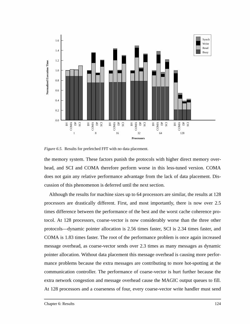
Chapter 6: Results 124
the memory system. These factors punish the protocols with higher direct memory over-
head, and SCI and COMA therefore perform worse in this less-tuned version. COMA
does not gain any relative performance advantage from the lack of data placement. Dis-
cussion of this phenomenon is deferred until the next section.
Although the results for machine sizes up to 64 processors are similar, the results at 128
processors are drastically different. First, and most importantly, there is now over 2.5
times difference between the performance of the best and the worst cache coherence pro-
tocol. At 128 processors, coarse-vector is now considerably worse than the three other
protocols—dynamic pointer allocation is 2.56 times faster, SCI is 2.34 times faster, and
COMA is 1.83 times faster. The root of the performance problem is once again increased
message overhead, as coarse-vector sends over 2.3 times as many messages as dynamic
pointer allocation. Without data placement this message overhead is causing more perfor-
mance problems because the extra messages are contributing to more hot-spotting at the
communication controller. The performance of coarse-vector is hurt further because the
extra network congestion and message overhead cause the MAGIC output queues to fill.
At 128 processors and a coarseness of four, every coarse-vector write handler must send
Figure 6.5. Results for prefetched FFT with no data placement.
BV
CO
MA DP
SCI
1
BV
CO
MA DP
SCI
8
BV
CO
MA DP
SCI
16B
V
CO
MA DP
SCI
32
BV
CO
MA DP
SCI
64
BV
CO
MA DP
SCI
128
Processors
0.0
0.2
0.4
0.6
0.8
1.0
1.2
1.4
1.6
Nor
mal
ized
Exe
cuti
on T
ime
Synch
Write
Read
Busy
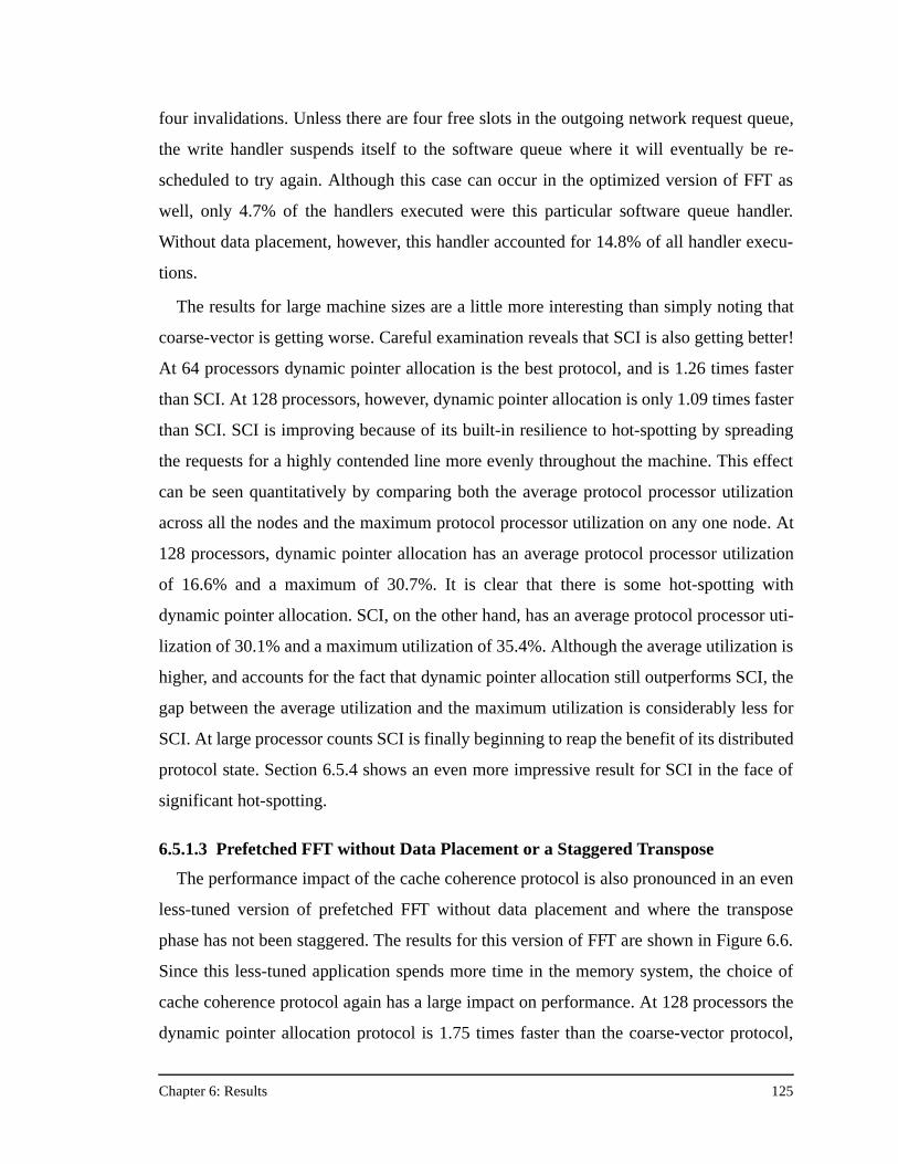
Chapter 6: Results 125
four invalidations. Unless there are four free slots in the outgoing network request queue,
the write handler suspends itself to the software queue where it will eventually be re-
scheduled to try again. Although this case can occur in the optimized version of FFT as
well, only 4.7% of the handlers executed were this particular software queue handler.
Without data placement, however, this handler accounted for 14.8% of all handler execu-
tions.
The results for large machine sizes are a little more interesting than simply noting that
coarse-vector is getting worse. Careful examination reveals that SCI is also getting better!
At 64 processors dynamic pointer allocation is the best protocol, and is 1.26 times faster
than SCI. At 128 processors, however, dynamic pointer allocation is only 1.09 times faster
than SCI. SCI is improving because of its built-in resilience to hot-spotting by spreading
the requests for a highly contended line more evenly throughout the machine. This effect
can be seen quantitatively by comparing both the average protocol processor utilization
across all the nodes and the maximum protocol processor utilization on any one node. At
128 processors, dynamic pointer allocation has an average protocol processor utilization
of 16.6% and a maximum of 30.7%. It is clear that there is some hot-spotting with
dynamic pointer allocation. SCI, on the other hand, has an average protocol processor uti-
lization of 30.1% and a maximum utilization of 35.4%. Although the average utilization is
higher, and accounts for the fact that dynamic pointer allocation still outperforms SCI, the
gap between the average utilization and the maximum utilization is considerably less for
SCI. At large processor counts SCI is finally beginning to reap the benefit of its distributed
protocol state. Section 6.5.4 shows an even more impressive result for SCI in the face of
significant hot-spotting.
6.5.1.3 Prefetched FFT without Data Placement or a Staggered Transpose
The performance impact of the cache coherence protocol is also pronounced in an even
less-tuned version of prefetched FFT without data placement and where the transpose
phase has not been staggered. The results for this version of FFT are shown in Figure 6.6.
Since this less-tuned application spends more time in the memory system, the choice of
cache coherence protocol again has a large impact on performance. At 128 processors the
dynamic pointer allocation protocol is 1.75 times faster than the coarse-vector protocol,
Chapter 6: Results 126
the SCI protocol is 1.21 times faster, and COMA is 1.18 times faster. With this version of
FFT, message overhead is still the main contributor to the performance difference between
the protocols. At 64 processors coarse-vector is sending 1.18 times more messages than
dynamic pointer allocation, and at 128 processors it jumps to 2.19 times more messages.
The principal difference between the previous version and this is that coarse-vector does
not perform as badly at 128 processors in this version. Only 10.7% (versus 14.8%) of the
protocol handlers are the software queue handlers for the invalidation continuations.
Surprisingly, for all machine sizes, even without data placement COMA does not per-
form as well as expected. Given COMA’s ability to migrate data at the hardware level
without programmer intervention, conventional wisdom would argue that COMA should
perform relatively better without data placement than with data placement. Unfortunately,
for both the previous version of FFT without data placement and this less-tuned version
without data placement, COMA performs worse than it does for the most optimized ver-
sion of FFT with explicit data placement.
BV
CO
MA DP
SCI
1
BV
CO
MA DP
SCI
8
BV
CO
MA DP
SCI
16
BV
CO
MA DP
SCI
32
BV
CO
MA DP
SCI
64
BV
CO
MA DP
SCI
128
Processors
0.0
0.2
0.4
0.6
0.8
1.0
1.2
1.4
1.6
1.8
Nor
mal
ized
Exe
cuti
on T
ime
Synch
Write
Read
Busy
Figure 6.6. Results for prefetched FFT with no data placement and an unstaggered transpose phase.
Chapter 6: Results 127
The even more surprising statistic is that the COMA attraction memory hit rate is much
higher in the versions of FFT without data placement, yet COMA’s relative performance is
worse. For the most optimized version of FFT, the percentage of remote reads satisfied
locally is less than 2.5% for all machine sizes. As mentioned in Section 6.5.1.1, FFT is
dominated by coherence misses and has very few capacity or conflict misses to bolster the
AM hit rate. For the less-tuned version of FFT without data placement, at 8 processors,
COMA locally satisfies 46% percent of the remote read misses, yet the bit-vector protocol
is still 1.45 times faster. As the machine size scales for FFT the percentage of remote read
misses goes up, offering potential benefit for COMA—but the absolute number of remote
read misses decreases with increasing processor count because of the increased total cache
size in the system. So for FFT, COMA achieves the best AM hit rate at 8 processors, but
any advantage in latency reduction is mitigated by COMA’s higher direct protocol over-
head. The average protocol processor utilization for COMA at 8 processors is 38%, versus
15.7% for the bit-vector protocol.
6.5.1.4 Less-Tuned FFT with 64 KB Processor Caches
Since large processor caches seem to mitigate any potential COMA performance advan-
tage, the same version of prefetched FFT shown in Figure 6.6 is simulated with a proces-
sor secondary cache size of 64 KB. With smaller caches there is more cache-block re-use,
and also far more conflict and capacity misses. In such situations COMA is expected to
thrive. The results for the 64 KB cache run are shown in Figure 6.7.
Surprisingly, COMA’s performance is much worse than expected despite AM hit rates
for remote reads around 70% at small machine sizes, and 45% at the largest machine sizes.
At 64 and 128 processors the coarse-vector protocol is 2.39 times and 2.34 times faster
than COMA, respectively. But note that the coarse-vector protocol is also over 2.64 times
faster than dynamic pointer allocation. The main performance culprit here is replacement
hints. Both COMA and dynamic pointer allocation use replacement hints to maintain pre-
cise sharing information. Even though COMA is expected to perform well with small
caches, the same small caches give rise to a large number of replacement hints. Replace-
ment hints invoke high-occupancy handlers that walk the linked list of sharers to remove
nodes from the list. The combination of large numbers of replacement hints and high-
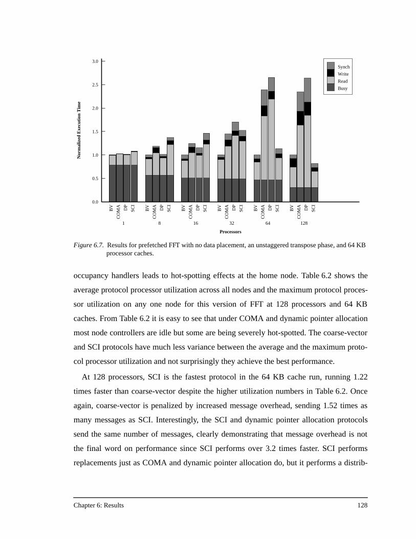
Chapter 6: Results 128
occupancy handlers leads to hot-spotting effects at the home node. Table 6.2 shows the
average protocol processor utilization across all nodes and the maximum protocol proces-
sor utilization on any one node for this version of FFT at 128 processors and 64 KB
caches. From Table 6.2 it is easy to see that under COMA and dynamic pointer allocation
most node controllers are idle but some are being severely hot-spotted. The coarse-vector
and SCI protocols have much less variance between the average and the maximum proto-
col processor utilization and not surprisingly they achieve the best performance.
At 128 processors, SCI is the fastest protocol in the 64 KB cache run, running 1.22
times faster than coarse-vector despite the higher utilization numbers in Table 6.2. Once
again, coarse-vector is penalized by increased message overhead, sending 1.52 times as
many messages as SCI. Interestingly, the SCI and dynamic pointer allocation protocols
send the same number of messages, clearly demonstrating that message overhead is not
the final word on performance since SCI performs over 3.2 times faster. SCI performs
replacements just as COMA and dynamic pointer allocation do, but it performs a distrib-
BV
CO
MA DP
SCI
1
BV
CO
MA DP
SCI
8
BV
CO
MA DP
SCI
16B
V
CO
MA DP
SCI
32
BV
CO
MA DP
SCI
64
BV
CO
MA DP
SCI
128
Processors
0.0
0.5
1.0
1.5
2.0
2.5
3.0
Nor
mal
ized
Exe
cuti
on T
ime
Synch
Write
Read
Busy
Figure 6.7. Results for prefetched FFT with no data placement, an unstaggered transpose phase, and 64 KB processor caches.
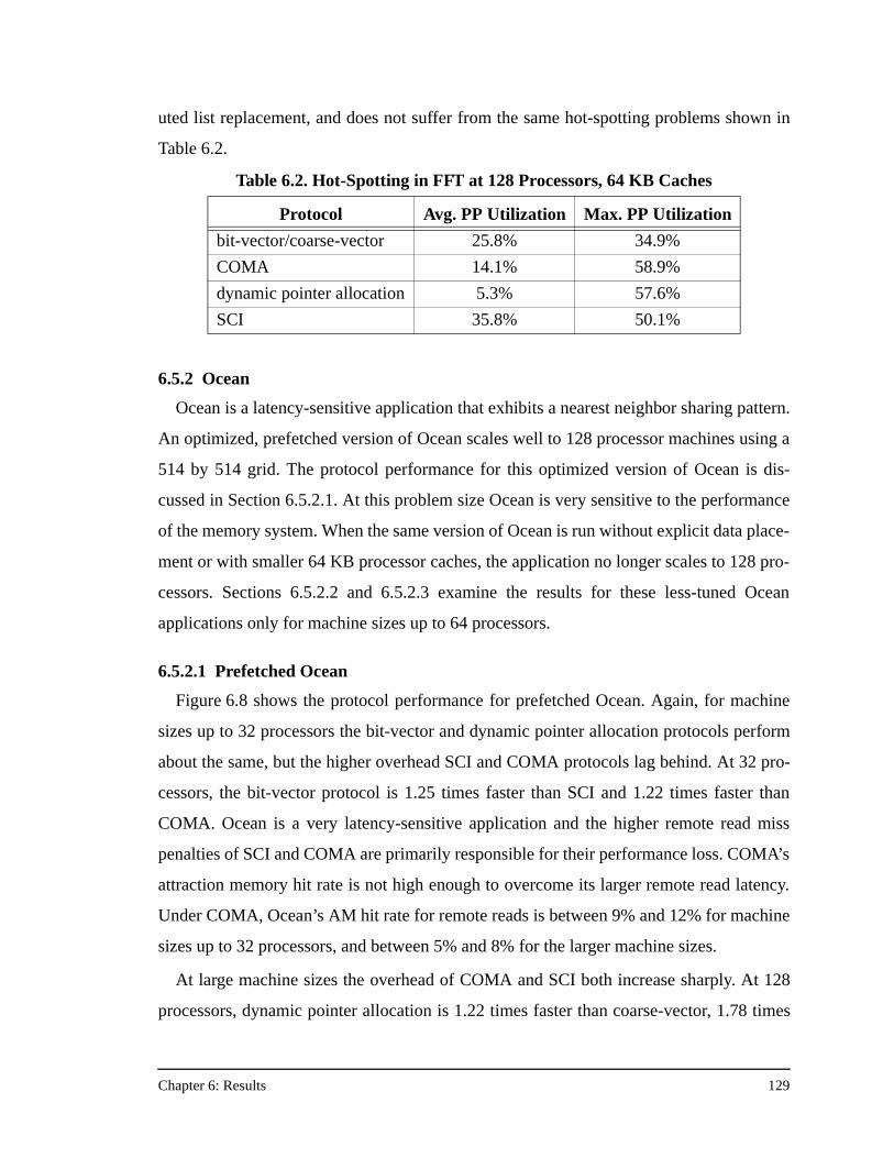
Chapter 6: Results 129
uted list replacement, and does not suffer from the same hot-spotting problems shown in
Table 6.2.
6.5.2 Ocean
Ocean is a latency-sensitive application that exhibits a nearest neighbor sharing pattern.
An optimized, prefetched version of Ocean scales well to 128 processor machines using a
514 by 514 grid. The protocol performance for this optimized version of Ocean is dis-
cussed in Section 6.5.2.1. At this problem size Ocean is very sensitive to the performance
of the memory system. When the same version of Ocean is run without explicit data place-
ment or with smaller 64 KB processor caches, the application no longer scales to 128 pro-
cessors. Sections 6.5.2.2 and 6.5.2.3 examine the results for these less-tuned Ocean
applications only for machine sizes up to 64 processors.
6.5.2.1 Prefetched Ocean
Figure 6.8 shows the protocol performance for prefetched Ocean. Again, for machine
sizes up to 32 processors the bit-vector and dynamic pointer allocation protocols perform
about the same, but the higher overhead SCI and COMA protocols lag behind. At 32 pro-
cessors, the bit-vector protocol is 1.25 times faster than SCI and 1.22 times faster than
COMA. Ocean is a very latency-sensitive application and the higher remote read miss
penalties of SCI and COMA are primarily responsible for their performance loss. COMA’s
attraction memory hit rate is not high enough to overcome its larger remote read latency.
Under COMA, Ocean’s AM hit rate for remote reads is between 9% and 12% for machine
sizes up to 32 processors, and between 5% and 8% for the larger machine sizes.
At large machine sizes the overhead of COMA and SCI both increase sharply. At 128
processors, dynamic pointer allocation is 1.22 times faster than coarse-vector, 1.78 times
Table 6.2. Hot-Spotting in FFT at 128 Processors, 64 KB Caches
Protocol Avg. PP Utilization Max. PP Utilization
bit-vector/coarse-vector 25.8% 34.9%
COMA 14.1% 58.9%
dynamic pointer allocation 5.3% 57.6%
SCI 35.8% 50.1%
Chapter 6: Results 130
faster than COMA, and 2.06 times faster than SCI. In this optimized version of Ocean the
performance problem at large processor counts is message overhead for SCI and a combi-
nation of low AM hit rate and protocol overhead-induced hot-spotting for COMA. SCI
sends 2.9 times the number of messages as dynamic pointer allocation, and more surpris-
ingly, 1.6 times more messages than the coarse-vector protocol with its imprecise sharing
information.
Part of the problem with SCI can be attributed to its distributed replacements, as Ocean,
with its large number of private arrays, is notorious for its processor cache conflicts. In
SCI, each cache replacement is a four message sequence rather the single replacement hint
message in either COMA or dynamic pointer allocation. Even on a uniprocessor, SCI’s
replacement overhead is higher than the other protocols because maintaining the replace-
ment buffer is a more complicated operation than handling a replacement hint. This is why
even at 1 processor, bit-vector is 1.14 times faster than SCI. The other problem for SCI is
its lack of forwarding. On a remote read miss, if a block is dirty in one of the processor
caches, the home node returns the identity of the dirty cache to the requester and the
requester must re-issue the read request to the dirty node. In the other three protocols the
BV
CO
MA DP
SCI
1
BV
CO
MA DP
SCI
8
BV
CO
MA DP
SCI
16B
V
CO
MA DP
SCI
32
BV
CO
MA DP
SCI
64
BV
CO
MA DP
SCI
128
Processors
0.0
0.2
0.4
0.6
0.8
1.0
1.2
1.4
1.6
1.8
Nor
mal
ized
Exe
cuti
on T
ime
Synch
Write
Read
Busy
Figure 6.8. Results for prefetched Ocean.
Chapter 6: Results 131
home node forwards the original read request directly to the dirty node. The result is a “4-
hop” read miss in SCI rather than the “3-hop” misses of the other protocols. If the home
node itself has the dirty data, then the FLASH SCI implementation handles that case in 2
hops, in the same manner as the other protocols. This was one of the FLASH-specific SCI
optimizations discussed in Section 4.4.2. This optimization is critical—for SCI at 128 pro-
cessors 67% of all remote reads are satisfied from the dirty processor cache at the home.
A final note of interest from Figure 6.8 is that at 64 processors the coarse-vector proto-
col is still the optimal protocol, running 1.10 times faster than dynamic pointer allocation.
In FFT, the increased message overhead of coarse-vector caused its performance to
degrade at 64 processors and dynamic pointer allocation was the best protocol. The differ-
ence here is that Ocean exhibits nearest-neighbor sharing patterns. This behavior maps
well onto the coarse-vector protocol because the nodes represented by a single bit in the
coarse-vector are neighbors, and thus the fact that coarse-vector has to send invalidations
to all the nodes represented by a single bit in the coarse-vector does not imply that the pro-
tocol is doing any “extra” work. That is, the protocols with precise sharing information
have to send the same number of invalidations. Consequently, the message overhead of
bit-vector/coarse-vector increases more slowly with machine size. At 128 processors
dynamic pointer allocation finally becomes the best protocol, because coarse-vector is at a
coarseness of four, and sending four invalidations is no longer the right thing to do. This
example illustrates how application-specific sharing patterns can affect which protocol is
best, or change the crossover point in performance between two protocols.
6.5.2.2 Prefetched Ocean without Data Placement
Although COMA’s AM hit rate for the optimized Ocean was still low at around 10%, it
is much higher than the hit rate for optimized FFT. Therefore it is reasonable to expect that
the AM hit rate will increase for a version of Ocean without explicit data placement, and
that this in turn will improve the relative performance of the COMA protocol. Figure 6.9
shows the results for the version of Ocean without data placement. Clearly, COMA is not
performing better; in fact, it is performing relatively worse than before. The bit-vector
protocol is 1.18 times faster than COMA at 8 processors, 1.49 times faster at 16 proces-
sors, and 2.34 times faster at 32 processors. However, the intuition about AM hit rates is
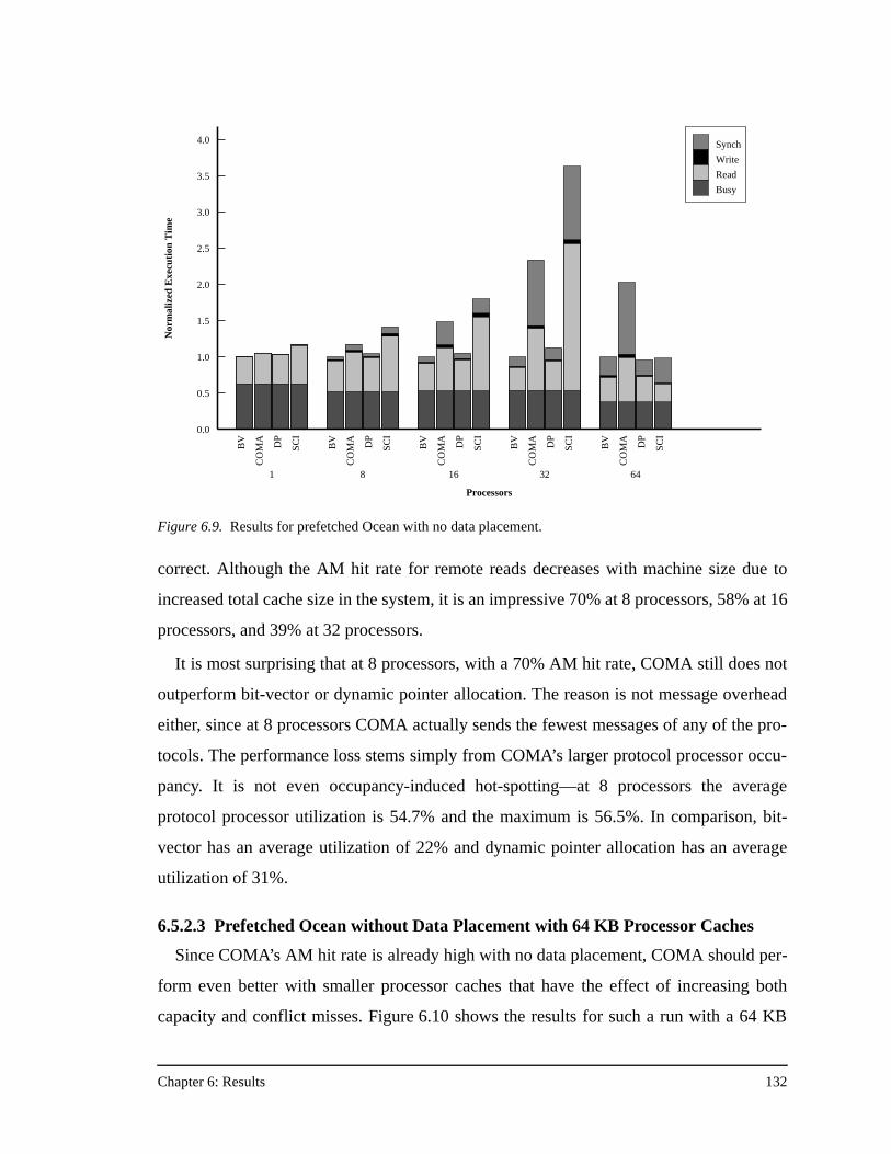
Chapter 6: Results 132
correct. Although the AM hit rate for remote reads decreases with machine size due to
increased total cache size in the system, it is an impressive 70% at 8 processors, 58% at 16
processors, and 39% at 32 processors.
It is most surprising that at 8 processors, with a 70% AM hit rate, COMA still does not
outperform bit-vector or dynamic pointer allocation. The reason is not message overhead
either, since at 8 processors COMA actually sends the fewest messages of any of the pro-
tocols. The performance loss stems simply from COMA’s larger protocol processor occu-
pancy. It is not even occupancy-induced hot-spotting—at 8 processors the average
protocol processor utilization is 54.7% and the maximum is 56.5%. In comparison, bit-
vector has an average utilization of 22% and dynamic pointer allocation has an average
utilization of 31%.
6.5.2.3 Prefetched Ocean without Data Placement with 64 KB Processor Caches
Since COMA’s AM hit rate is already high with no data placement, COMA should per-
form even better with smaller processor caches that have the effect of increasing both
capacity and conflict misses. Figure 6.10 shows the results for such a run with a 64 KB
BV
CO
MA DP
SCI
1
BV
CO
MA DP
SCI
8
BV
CO
MA DP
SCI
16
BV
CO
MA DP
SCI
32
BV
CO
MA DP
SCI
64
Processors
0.0
0.5
1.0
1.5
2.0
2.5
3.0
3.5
4.0
Nor
mal
ized
Exe
cuti
on T
ime
Synch
Write
Read
Busy
Figure 6.9. Results for prefetched Ocean with no data placement.
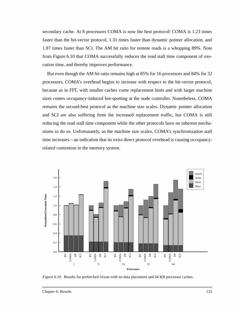
Chapter 6: Results 133
secondary cache. At 8 processors COMA is now the best protocol! COMA is 1.23 times
faster than the bit-vector protocol, 1.31 times faster than dynamic pointer allocation, and
1.87 times faster than SCI. The AM hit ratio for remote reads is a whopping 89%. Note
from Figure 6.10 that COMA successfully reduces the read stall time component of exe-
cution time, and thereby improves performance.
But even though the AM hit ratio remains high at 85% for 16 processors and 84% for 32
processors, COMA’s overhead begins to increase with respect to the bit-vector protocol,
because as in FFT, with smaller caches come replacement hints and with larger machine
sizes comes occupancy-induced hot-spotting at the node controller. Nonetheless, COMA
remains the second-best protocol as the machine size scales. Dynamic pointer allocation
and SCI are also suffering from the increased replacement traffic, but COMA is still
reducing the read stall time component while the other protocols have no inherent mecha-
nisms to do so. Unfortunately, as the machine size scales, COMA’s synchronization stall
time increases—an indication that its extra direct protocol overhead is causing occupancy-
related contention in the memory system.
BV
CO
MA DP
SCI
1
BV
CO
MA DP
SCI
8
BV
CO
MA DP
SCI
16
BV
CO
MA DP
SCI
32
BV
CO
MA DP
SCI
64
Processors
0.0
0.2
0.4
0.6
0.8
1.0
1.2
1.4
1.6
Nor
mal
ized
Exe
cuti
on T
ime
Synch
Write
Read
Busy
Figure 6.10. Results for prefetched Ocean with no data placement and 64 KB processor caches.
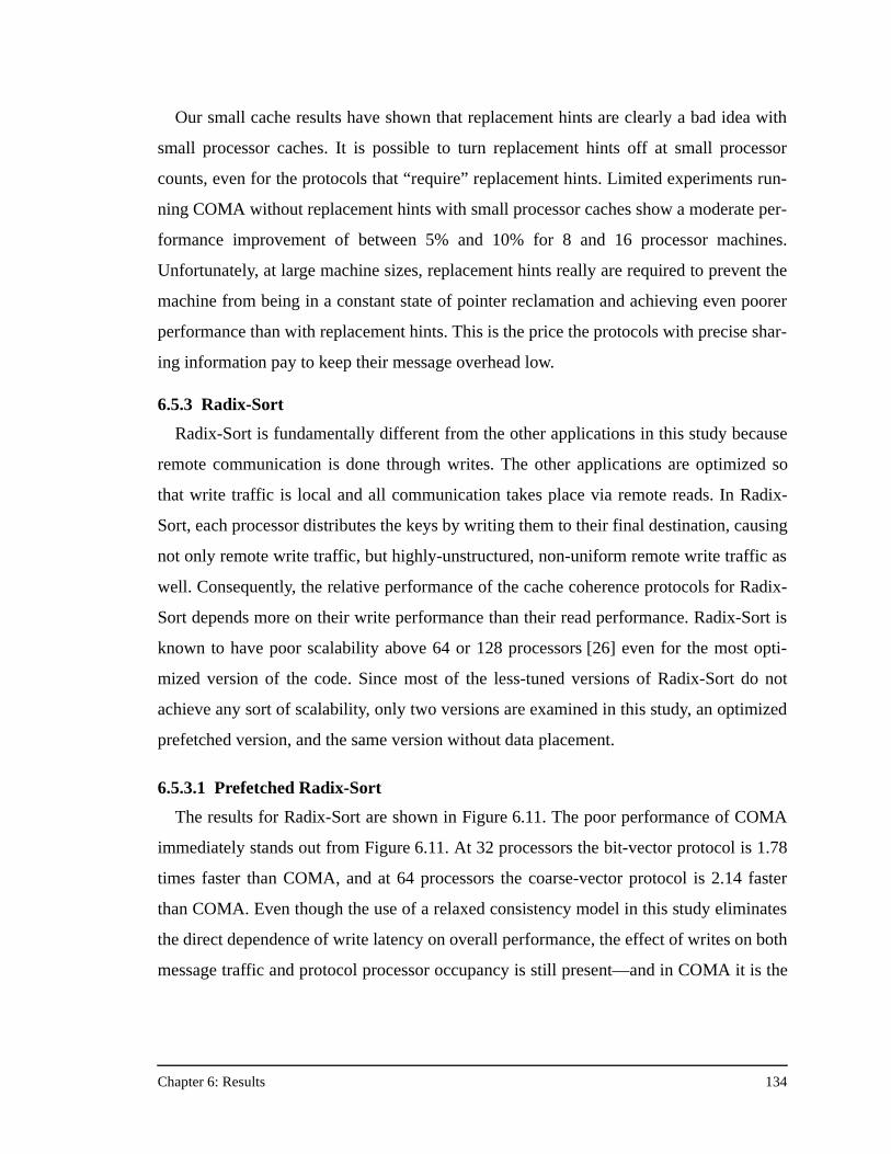
Chapter 6: Results 134
Our small cache results have shown that replacement hints are clearly a bad idea with
small processor caches. It is possible to turn replacement hints off at small processor
counts, even for the protocols that “require” replacement hints. Limited experiments run-
ning COMA without replacement hints with small processor caches show a moderate per-
formance improvement of between 5% and 10% for 8 and 16 processor machines.
Unfortunately, at large machine sizes, replacement hints really are required to prevent the
machine from being in a constant state of pointer reclamation and achieving even poorer
performance than with replacement hints. This is the price the protocols with precise shar-
ing information pay to keep their message overhead low.
6.5.3 Radix-Sort
Radix-Sort is fundamentally different from the other applications in this study because
remote communication is done through writes. The other applications are optimized so
that write traffic is local and all communication takes place via remote reads. In Radix-
Sort, each processor distributes the keys by writing them to their final destination, causing
not only remote write traffic, but highly-unstructured, non-uniform remote write traffic as
well. Consequently, the relative performance of the cache coherence protocols for Radix-
Sort depends more on their write performance than their read performance. Radix-Sort is
known to have poor scalability above 64 or 128 processors [26] even for the most opti-
mized version of the code. Since most of the less-tuned versions of Radix-Sort do not
achieve any sort of scalability, only two versions are examined in this study, an optimized
prefetched version, and the same version without data placement.
6.5.3.1 Prefetched Radix-Sort
The results for Radix-Sort are shown in Figure 6.11. The poor performance of COMA
immediately stands out from Figure 6.11. At 32 processors the bit-vector protocol is 1.78
times faster than COMA, and at 64 processors the coarse-vector protocol is 2.14 faster
than COMA. Even though the use of a relaxed consistency model in this study eliminates
the direct dependence of write latency on overall performance, the effect of writes on both
message traffic and protocol processor occupancy is still present—and in COMA it is the
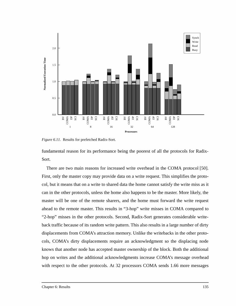
Chapter 6: Results 135
fundamental reason for its performance being the poorest of all the protocols for Radix-
Sort.
There are two main reasons for increased write overhead in the COMA protocol [50].
First, only the master copy may provide data on a write request. This simplifies the proto-
col, but it means that on a write to shared data the home cannot satisfy the write miss as it
can in the other protocols, unless the home also happens to be the master. More likely, the
master will be one of the remote sharers, and the home must forward the write request
ahead to the remote master. This results in “3-hop” write misses in COMA compared to
“2-hop” misses in the other protocols. Second, Radix-Sort generates considerable write-
back traffic because of its random write pattern. This also results in a large number of dirty
displacements from COMA’s attraction memory. Unlike the writebacks in the other proto-
cols, COMA’s dirty displacements require an acknowledgment so the displacing node
knows that another node has accepted master ownership of the block. Both the additional
hop on writes and the additional acknowledgments increase COMA’s message overhead
with respect to the other protocols. At 32 processors COMA sends 1.66 more messages
BV
CO
MA DP
SCI
1
BV
CO
MA DP
SCI
8
BV
CO
MA DP
SCI
16B
V
CO
MA DP
SCI
32
BV
CO
MA DP
SCI
64
BV
CO
MA DP
SCI
128
Processors
0.0
0.5
1.0
1.5
2.0N
orm
aliz
ed E
xecu
tion
Tim
e
Synch
Write
Read
Busy
Figure 6.11. Results for prefetched Radix-Sort.
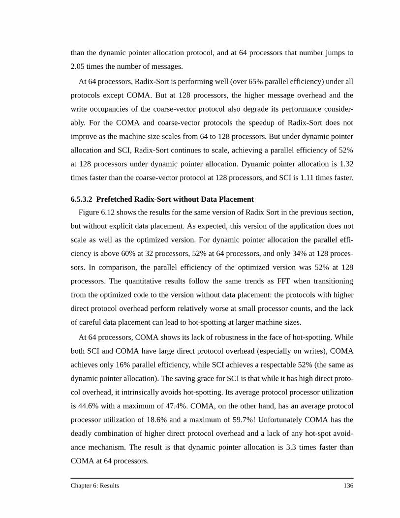
Chapter 6: Results 136
than the dynamic pointer allocation protocol, and at 64 processors that number jumps to
2.05 times the number of messages.
At 64 processors, Radix-Sort is performing well (over 65% parallel efficiency) under all
protocols except COMA. But at 128 processors, the higher message overhead and the
write occupancies of the coarse-vector protocol also degrade its performance consider-
ably. For the COMA and coarse-vector protocols the speedup of Radix-Sort does not
improve as the machine size scales from 64 to 128 processors. But under dynamic pointer
allocation and SCI, Radix-Sort continues to scale, achieving a parallel efficiency of 52%
at 128 processors under dynamic pointer allocation. Dynamic pointer allocation is 1.32
times faster than the coarse-vector protocol at 128 processors, and SCI is 1.11 times faster.
6.5.3.2 Prefetched Radix-Sort without Data Placement
Figure 6.12 shows the results for the same version of Radix Sort in the previous section,
but without explicit data placement. As expected, this version of the application does not
scale as well as the optimized version. For dynamic pointer allocation the parallel effi-
ciency is above 60% at 32 processors, 52% at 64 processors, and only 34% at 128 proces-
sors. In comparison, the parallel efficiency of the optimized version was 52% at 128
processors. The quantitative results follow the same trends as FFT when transitioning
from the optimized code to the version without data placement: the protocols with higher
direct protocol overhead perform relatively worse at small processor counts, and the lack
of careful data placement can lead to hot-spotting at larger machine sizes.
At 64 processors, COMA shows its lack of robustness in the face of hot-spotting. While
both SCI and COMA have large direct protocol overhead (especially on writes), COMA
achieves only 16% parallel efficiency, while SCI achieves a respectable 52% (the same as
dynamic pointer allocation). The saving grace for SCI is that while it has high direct proto-
col overhead, it intrinsically avoids hot-spotting. Its average protocol processor utilization
is 44.6% with a maximum of 47.4%. COMA, on the other hand, has an average protocol
processor utilization of 18.6% and a maximum of 59.7%! Unfortunately COMA has the
deadly combination of higher direct protocol overhead and a lack of any hot-spot avoid-
ance mechanism. The result is that dynamic pointer allocation is 3.3 times faster than
COMA at 64 processors.
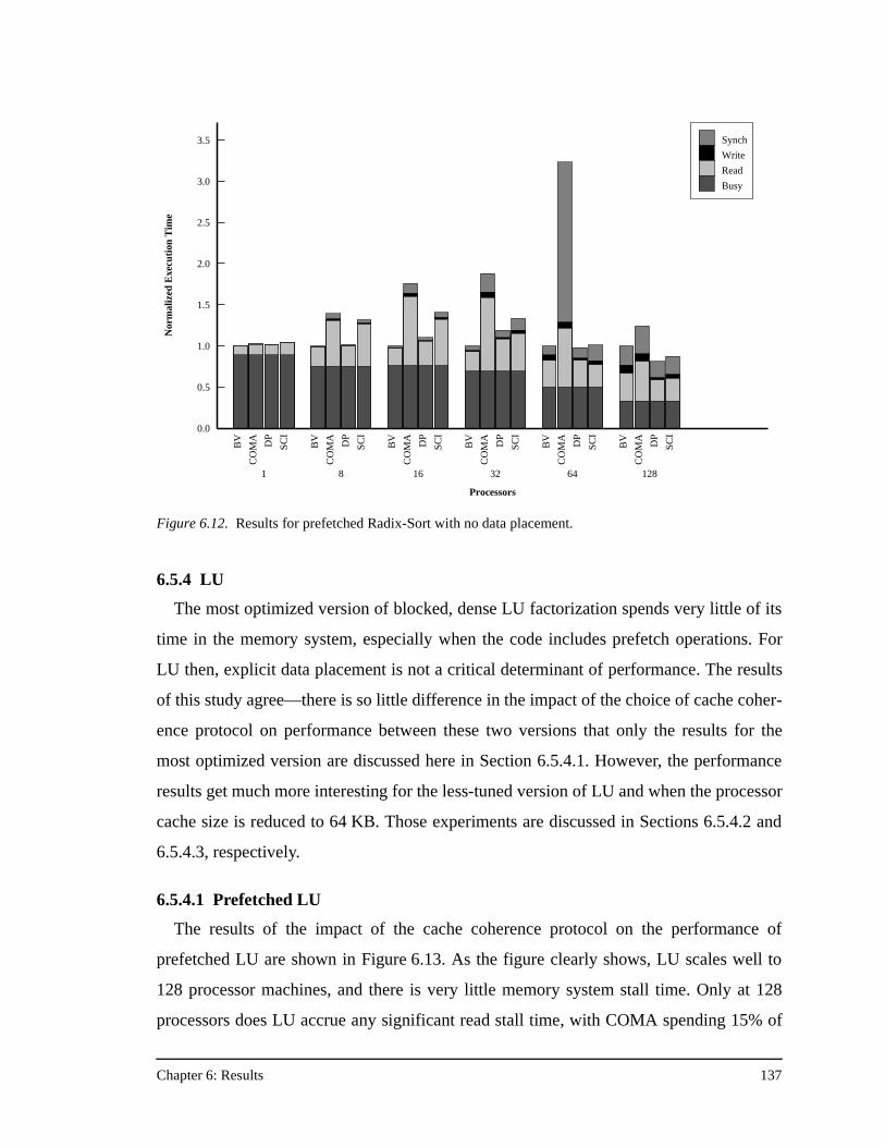
Chapter 6: Results 137
6.5.4 LU
The most optimized version of blocked, dense LU factorization spends very little of its
time in the memory system, especially when the code includes prefetch operations. For
LU then, explicit data placement is not a critical determinant of performance. The results
of this study agree—there is so little difference in the impact of the choice of cache coher-
ence protocol on performance between these two versions that only the results for the
most optimized version are discussed here in Section 6.5.4.1. However, the performance
results get much more interesting for the less-tuned version of LU and when the processor
cache size is reduced to 64 KB. Those experiments are discussed in Sections 6.5.4.2 and
6.5.4.3, respectively.
6.5.4.1 Prefetched LU
The results of the impact of the cache coherence protocol on the performance of
prefetched LU are shown in Figure 6.13. As the figure clearly shows, LU scales well to
128 processor machines, and there is very little memory system stall time. Only at 128
processors does LU accrue any significant read stall time, with COMA spending 15% of
BV
CO
MA DP
SCI
1
BV
CO
MA DP
SCI
8
BV
CO
MA DP
SCI
16B
V
CO
MA DP
SCI
32
BV
CO
MA DP
SCI
64
BV
CO
MA DP
SCI
128
Processors
0.0
0.5
1.0
1.5
2.0
2.5
3.0
3.5
Nor
mal
ized
Exe
cuti
on T
ime
Synch
Write
Read
Busy
Figure 6.12. Results for prefetched Radix-Sort with no data placement.
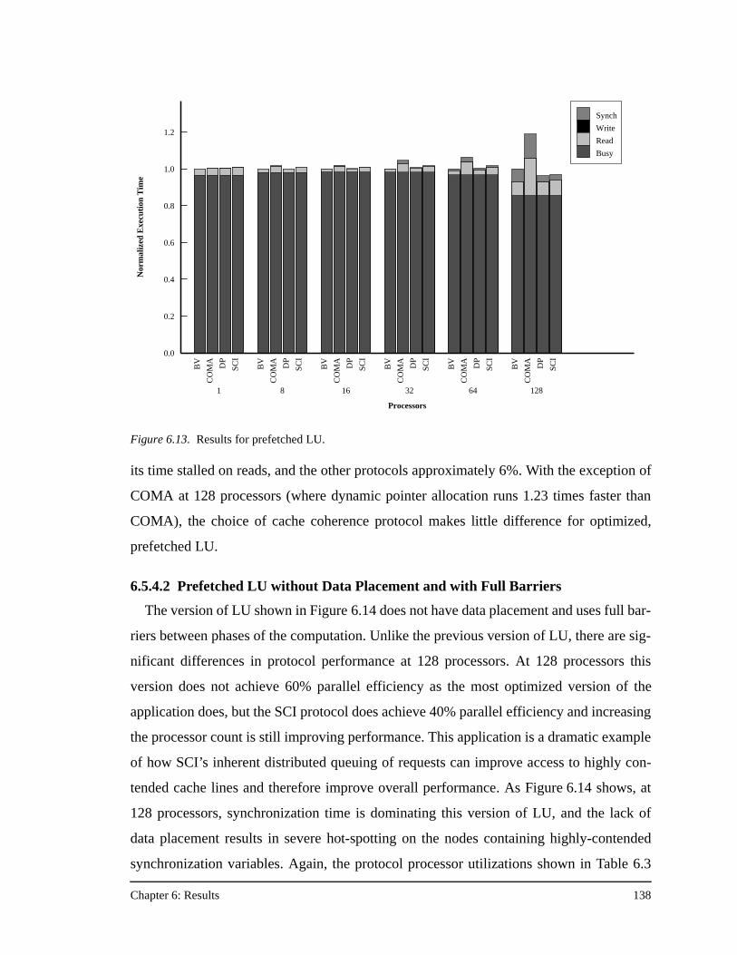
Chapter 6: Results 138
its time stalled on reads, and the other protocols approximately 6%. With the exception of
COMA at 128 processors (where dynamic pointer allocation runs 1.23 times faster than
COMA), the choice of cache coherence protocol makes little difference for optimized,
prefetched LU.
6.5.4.2 Prefetched LU without Data Placement and with Full Barriers
The version of LU shown in Figure 6.14 does not have data placement and uses full bar-
riers between phases of the computation. Unlike the previous version of LU, there are sig-
nificant differences in protocol performance at 128 processors. At 128 processors this
version does not achieve 60% parallel efficiency as the most optimized version of the
application does, but the SCI protocol does achieve 40% parallel efficiency and increasing
the processor count is still improving performance. This application is a dramatic example
of how SCI’s inherent distributed queuing of requests can improve access to highly con-
tended cache lines and therefore improve overall performance. As Figure 6.14 shows, at
128 processors, synchronization time is dominating this version of LU, and the lack of
data placement results in severe hot-spotting on the nodes containing highly-contended
synchronization variables. Again, the protocol processor utilizations shown in Table 6.3
Figure 6.13. Results for prefetched LU.
BV
CO
MA DP
SCI
1
BV
CO
MA DP
SCI
8
BV
CO
MA DP
SCI
16B
V
CO
MA DP
SCI
32
BV
CO
MA DP
SCI
64
BV
CO
MA DP
SCI
128
Processors
0.0
0.2
0.4
0.6
0.8
1.0
1.2N
orm
aliz
ed E
xecu
tion
Tim
e
Synch
Write
Read
Busy
Chapter 6: Results 139
show the effect of the SCI protocol in the face of severe application hot-spotting behavior.
While SCI has a much higher average protocol processor utilization, the maximum utiliza-
tion on any node is drastically smaller, and the variance between the two is by far the low-
est of any of the protocols. The result is that despite having the largest message overhead,
SCI has the least synchronization stall time and is the best protocol at large machine
sizes—2.25 times faster than the coarse-vector protocol at 128 processors.
Figure 6.14. Results for prefetched LU with no data placement, and full barriers between the three commu-nication phases.
BV
CO
MA DP
SCI
1
BV
CO
MA DP
SCI
8
BV
CO
MA DP
SCI
16B
V
CO
MA DP
SCI
32
BV
CO
MA DP
SCI
64
BV
CO
MA DP
SCI
128
Processors
0.0
0.2
0.4
0.6
0.8
1.0
1.2N
orm
aliz
ed E
xecu
tion
Tim
e
Synch
Write
Read
Busy
Table 6.3. SCI’s Aversion to Hot-Spotting at 128 Processors
Protocol Avg. PP Utilization Max. PP Utilization
bit-vector/coarse-vector 1.7% 85.1%
COMA 4.9% 69.5%
dynamic pointer allocation 2.2% 60.9%
SCI 22.0% 32.2%
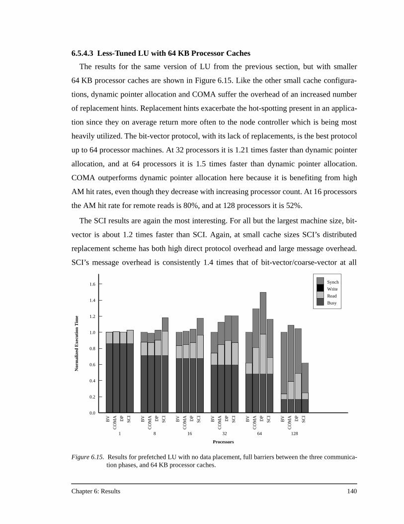
Chapter 6: Results 140
6.5.4.3 Less-Tuned LU with 64 KB Processor Caches
The results for the same version of LU from the previous section, but with smaller
64 KB processor caches are shown in Figure 6.15. Like the other small cache configura-
tions, dynamic pointer allocation and COMA suffer the overhead of an increased number
of replacement hints. Replacement hints exacerbate the hot-spotting present in an applica-
tion since they on average return more often to the node controller which is being most
heavily utilized. The bit-vector protocol, with its lack of replacements, is the best protocol
up to 64 processor machines. At 32 processors it is 1.21 times faster than dynamic pointer
allocation, and at 64 processors it is 1.5 times faster than dynamic pointer allocation.
COMA outperforms dynamic pointer allocation here because it is benefiting from high
AM hit rates, even though they decrease with increasing processor count. At 16 processors
the AM hit rate for remote reads is 80%, and at 128 processors it is 52%.
The SCI results are again the most interesting. For all but the largest machine size, bit-
vector is about 1.2 times faster than SCI. Again, at small cache sizes SCI’s distributed
replacement scheme has both high direct protocol overhead and large message overhead.
SCI’s message overhead is consistently 1.4 times that of bit-vector/coarse-vector at all
BV
CO
MA DP
SCI
1
BV
CO
MA DP
SCI
8
BV
CO
MA DP
SCI
16
BV
CO
MA DP
SCI
32
BV
CO
MA DP
SCI
64
BV
CO
MA DP
SCI
128
Processors
0.0
0.2
0.4
0.6
0.8
1.0
1.2
1.4
1.6
Nor
mal
ized
Exe
cuti
on T
ime
Synch
Write
Read
Busy
Figure 6.15. Results for prefetched LU with no data placement, full barriers between the three communica-tion phases, and 64 KB processor caches.
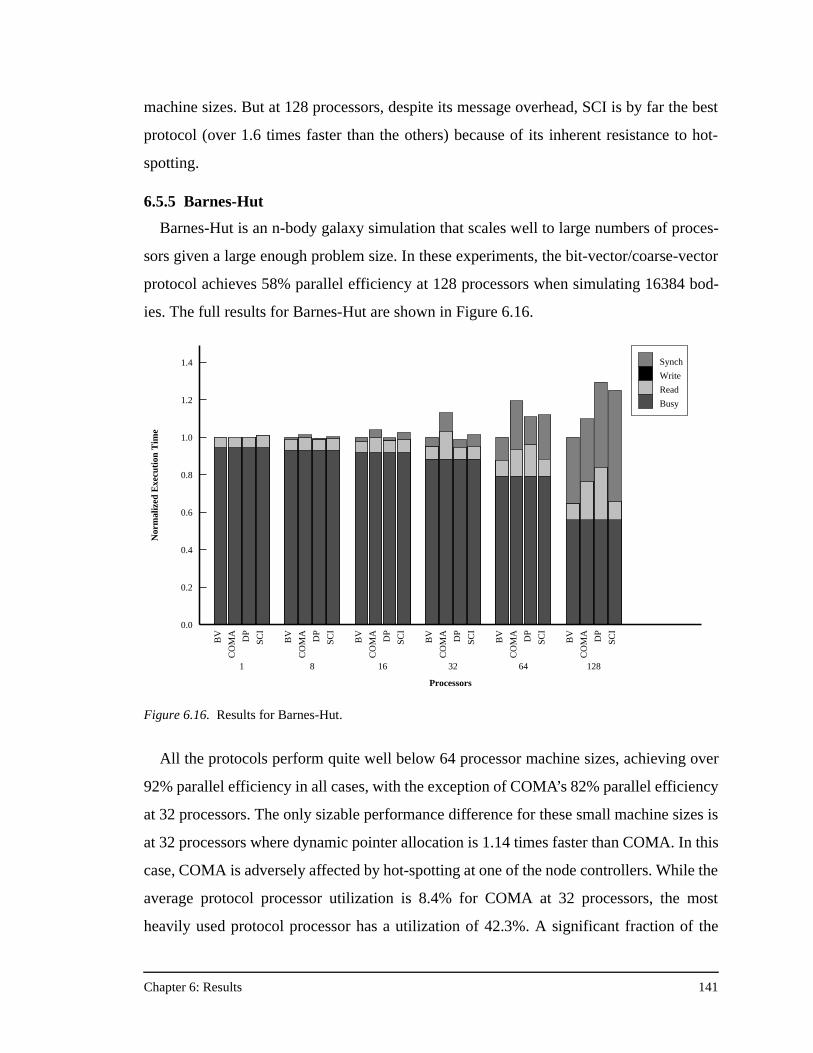
Chapter 6: Results 141
machine sizes. But at 128 processors, despite its message overhead, SCI is by far the best
protocol (over 1.6 times faster than the others) because of its inherent resistance to hot-
spotting.
6.5.5 Barnes-Hut
Barnes-Hut is an n-body galaxy simulation that scales well to large numbers of proces-
sors given a large enough problem size. In these experiments, the bit-vector/coarse-vector
protocol achieves 58% parallel efficiency at 128 processors when simulating 16384 bod-
ies. The full results for Barnes-Hut are shown in Figure 6.16.
All the protocols perform quite well below 64 processor machine sizes, achieving over
92% parallel efficiency in all cases, with the exception of COMA’s 82% parallel efficiency
at 32 processors. The only sizable performance difference for these small machine sizes is
at 32 processors where dynamic pointer allocation is 1.14 times faster than COMA. In this
case, COMA is adversely affected by hot-spotting at one of the node controllers. While the
average protocol processor utilization is 8.4% for COMA at 32 processors, the most
heavily used protocol processor has a utilization of 42.3%. A significant fraction of the
Figure 6.16. Results for Barnes-Hut.
BV
CO
MA DP
SCI
1
BV
CO
MA DP
SCI
8
BV
CO
MA DP
SCI
16
BV
CO
MA DP
SCI
32
BV
CO
MA DP
SCI
64
BV
CO
MA DP
SCI
128
Processors
0.0
0.2
0.4
0.6
0.8
1.0
1.2
1.4
Nor
mal
ized
Exe
cuti
on T
ime
Synch
Write
Read
Busy
Chapter 6: Results 142
read misses (37%) in Barnes-Hut are “3-hop” dirty remote misses—a case where COMA
has a higher direct protocol overhead than the other protocols—and the AM hit rate of
30% is not enough to balance out this overhead increase.
At larger machine sizes, load imbalance becomes the bottleneck in Barnes-Hut, and
application synchronization stall times dominate the total stall time. The bit-vector/coarse-
vector is by far the best protocol at both 64 and 128 processors. Unlike the previous appli-
cations, Barnes-Hut has many cache lines that are shared amongst all of the processors.
Long sharing lists help the bit-vector/coarse-vector protocol because there is a larger
chance that it will not be sending unnecessary invalidations on write misses. Long sharing
lists also hurt dynamic pointer allocation and COMA, because replacement hints have to
traverse a long linked list to remove a node from the sharing list, resulting in a high occu-
pancy protocol handler. This can degrade performance by creating a hot-spot at the home
node for the replaced block. SCI is indirectly hurt by long sharing lists for two reasons:
invalidating long lists is slower on SCI than the other protocols due to its serial invalida-
tion scheme, and cache replacements from the middle of an SCI sharing list have higher
overhead than a replacement from a sharing list with two or fewer sharers.
6.5.6 Water
The final application examined in this study is Water, a cutoff-radius n-body application
from the field of computational chemistry. The protocol performance results for the most
optimized version of Water are shown in Figure 6.17. Like Barnes-Hut, Water has long
sharing lists, which hurt the performance of dynamic pointer allocation and COMA at the
largest machine sizes.
The results in Figure 6.17 show that at small machine sizes Water does not do a lot of
communication and all the protocols perform equally well. But at 32 processors and
above, the presence of long sharing lists begins to affect COMA and dynamic pointer allo-
cation. At 64 processors the coarse-vector protocol is 1.21 times faster than COMA and
1.14 times faster than dynamic pointer allocation. At 128 processors SCI is the fastest pro-
tocol, achieving 3.2% better performance than the coarse-vector protocol even though it
sends 1.83 times more messages (the most of any protocol). Again, SCI’s even message
distribution reduces contention and therefore memory system stall time.
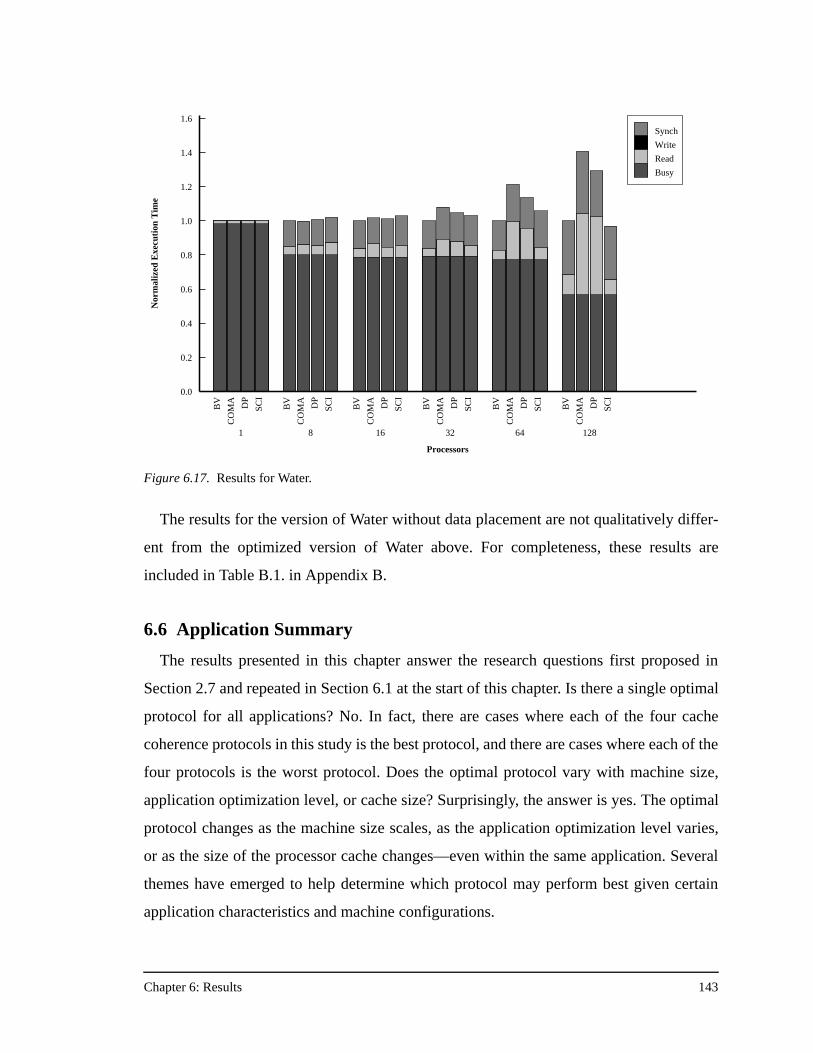
Chapter 6: Results 143
The results for the version of Water without data placement are not qualitatively differ-
ent from the optimized version of Water above. For completeness, these results are
included in Table B.1. in Appendix B.
6.6 Application Summary
The results presented in this chapter answer the research questions first proposed in
Section 2.7 and repeated in Section 6.1 at the start of this chapter. Is there a single optimal
protocol for all applications? No. In fact, there are cases where each of the four cache
coherence protocols in this study is the best protocol, and there are cases where each of the
four protocols is the worst protocol. Does the optimal protocol vary with machine size,
application optimization level, or cache size? Surprisingly, the answer is yes. The optimal
protocol changes as the machine size scales, as the application optimization level varies,
or as the size of the processor cache changes—even within the same application. Several
themes have emerged to help determine which protocol may perform best given certain
application characteristics and machine configurations.
BV
CO
MA DP
SCI
1
BV
CO
MA DP
SCI
8
BV
CO
MA DP
SCI
16B
V
CO
MA DP
SCI
32
BV
CO
MA DP
SCI
64
BV
CO
MA DP
SCI
128
Processors
0.0
0.2
0.4
0.6
0.8
1.0
1.2
1.4
1.6
Nor
mal
ized
Exe
cuti
on T
ime
Synch
Write
Read
Busy
Figure 6.17. Results for Water.
Chapter 6: Results 144
First, the bit-vector protocol is difficult to beat at small-to-medium scale machines
before it turns coarse. It is so efficient that only COMA, which can convert remote misses
into local misses, ever beats the bit-vector protocol below 32 processors, and even then it
only occurred in this study for some 8-processor machines configured with small proces-
sor caches. For the large cache configurations, dynamic pointer allocation typically per-
forms about as well as the bit-vector protocol for these small machine sizes. SCI on the
other hand, always performs poorly at low processor counts, regardless of the processor
cache size or application characteristics. Relative to bit-vector and dynamic pointer alloca-
tion, the large direct protocol overhead and message overhead of SCI yield uncompetitive
performance for small machine sizes.
Second, with small processor caches where COMA is expected to perform better, it suf-
fers the same fate as dynamic pointer allocation—small processor caches translates to
large numbers of replacement hints. With small processor caches the protocols without
replacement hints (bit-vector/coarse-vector and SCI) generally outperform the protocols
with replacement hints.
Third, although the bit-vector/coarse-vector, dynamic pointer allocation, and COMA
protocols on average all incur less protocol processor occupancy than the SCI protocol,
SCI incurs occupancy at the requester rather than the home. This occupancy at the
requester is the result of SCI maintaining its most complex data structures, the duplicate
tags and the replacement buffer, at the requester. The advantage of keeping this distributed
state is the ability to form a distributed queue for highly-contended lines and more evenly
distribute the retried requests throughout the machine. For applications which exhibit sig-
nificant hot-spotting behavior at large numbers of processors, SCI may be the most robust
protocol.
Fourth, for applications with a small, fixed number of sharers (e.g., FFT and Ocean)
running on machines with large processor caches, the dynamic pointer allocation protocol
performs well at all machine sizes, and is the best protocol at the largest machine sizes
because replacement hints do not cause performance problems with small sharing lists.
For these same applications at large machine sizes, the coarse-vector protocol usually per-
forms poorly because of increased message overhead due to its lack of precise sharing
information.
Chapter 6: Results 145
Fifth, the COMA protocol can achieve very high attraction memory hit rates on applica-
tions that do not perform data placement, but its higher remote read miss latencies and
generally higher protocol processor occupancies often remain too large to overcome. With
large processor caches and the most optimized versions of the parallel applications, the
attraction memory hit rates are extremely poor because the large caches remove most
capacity and conflict misses, and the optimized applications incur cache misses only for
true communication misses for which COMA is of no use.
Finally, increased message overhead is often the root of the performance difference
between the protocols at large machine sizes. However, this is not always the case. While
message overhead is a key issue, other effects such as hot-spotting or an abundance of
high-occupancy protocol handlers are usually more important to overall performance. In
the absence of these other effects (usually in optimized applications) message overhead is
a key determinant of performance. But when hot-spotting or high-occupancy handlers are
present, these effects dominate. This explains why SCI, which shows an aversion to hot-
spotting, can be the best protocol at 128 processors for less-tuned applications despite the
fact that it has the largest message overhead.
Chapter 7: Conclusions, Related Work, and Beyond 146
Chapter 7
Conclusions, Related Work, and Beyond
This implementation-based, quantitative comparison of scalable cache coherence proto-
cols is made feasible by taking advantage of the flexibility of MAGIC, the node controller
of the Stanford FLASH multiprocessor. While holding constant both the application and
the other aspects of the FLASH architecture (microprocessor, memory, network, and I/O
subsystems), the FLASH machine can vary only the cache coherence protocol that runs on
its programmable protocol processor. Four such cache coherence protocols have been
designed and implemented for the FLASH machine: bit-vector/coarse-vector, dynamic
pointer allocation, SCI, and COMA. This study details the design of each of these four
popular protocols, and compares their performance and robustness on machine sizes from
1 to 128 processors.
The results demonstrate that protocols with small latency differences can still have large
overall performance differences because controller occupancy is a key to robust perfor-
mance in CC-NUMA machines. The importance of controller occupancy increases with
machine size, as parallel applications hit scalability bottlenecks as a result of hot-spotting
in the memory system or at the node controller. The protocols with the highest controller
occupancies typically perform the worst, with the notable exception of SCI. At small pro-
cessor counts SCI, with its high controller occupancy, does indeed perform badly. But at
large processor counts SCI is sometimes the best protocol despite its large controller occu-
pancy, because it incurs that occupancy at the requester rather than home, thereby avoid-
ing the performance degradation that hot-spotting is causing in the other home-based
protocols.
Surprisingly, this study finds that the optimal protocol changes as the machine size
scales—even within the same application. In addition, changing architectural aspects
other than machine size (like cache size) can change the optimal coherence protocol. Both
of these findings are of particular interest to commercial industry, where today the choice
of cache coherence protocol is made at design time and is fixed by the hardware. If a cus-
tomer wants to run FFT with a 16-processor machine, the right protocol to use is bit-vec-
Chapter 7: Conclusions, Related Work, and Beyond 147
tor/coarse-vector. But if that same customer later upgrades to a 128-processor machine to
run FFT, bit-vector/coarse-vector would be the worst protocol choice.
In the end, the results of this study argue for programmable protocols on scalable
machines, or a newer and more flexible cache coherence protocol. For designers who want
a single architecture to span machine sizes and cache configurations with robust perfor-
mance across a wide spectrum of applications using existing cache coherence protocols,
flexibility in the choice of cache coherence protocol is vital. Ideas for the alternative direc-
tion of designing a single, more robust protocol are discussed in Section 7.2.
7.1 Related Work
Early work in directory cache coherence protocols focused on designing directory orga-
nizations that allow the memory overhead to scale gracefully with the number of proces-
sors. Fruits of this research were the coarse-vector, dynamic pointer allocation, and SCI
protocols examined in this dissertation. In addition, there were some other significant pro-
tocols developed during this period.
Weber developed the concept of sparse directories [61], which is a technique to reduce
the number of directory entries by caching only the most recently used entries. Prior tech-
niques to reduce the size of the directory focused on changing only the format or width of
the directory entries themselves. The sparse directory technique could easily be applicable
to any of the protocols discussed in this dissertation, although these protocols already have
acceptable memory overhead levels.
Chaiken et al. developed the LimitLESS protocol [10] that keeps a small, fixed number
of pointers in hardware (one in their implementation) and then traps to software to handle
any exceptional cases. The advantages of this scheme are low memory overhead and sim-
pler control logic since the node controller handles only the trivial protocol cases. The dis-
advantage of this protocol is that it must interrupt the compute processor to handle the
exceptional cases. For good performance this requires both that the exceptional cases are
rare, and that the compute processor has low interrupt overhead, something that is not typ-
ical of current microprocessors. Still, at a high level, the LimitLESS protocol shares the
same design philosophy as the MAGIC chip: keep the complicated protocol logic under
Chapter 7: Conclusions, Related Work, and Beyond 148
software control. The difference being that the MAGIC approach is a co-processor imple-
mentation that performs the data movement in hardware and eliminates the need to send
interrupts to the main processor, with the goal of better overlapping communication with
computation.
After the advent of these directory-based coherence protocols, several researchers
attempted to compare their performance. Stenstrom and Joe performed a qualitative and
quantitative comparison of the bit-vector and original hierarchical COMA protocols [53].
Unlike the performance comparison in this dissertation, their study was based on high-
level descriptions of the protocols, and it is not clear if the direct protocol overhead of the
protocols they examined accurately reflects any implementation of those protocols. How-
ever, the main contribution of the paper is that a hybrid CC-NUMA/COMA protocol,
COMA-F (the COMA protocol examined in this dissertation) outperforms the original
hierarchical COMA protocol.
Singh et al. also compared the performance of CC-NUMA and COMA machines, but
they compared actual implementations of each architecture [46]. The CC-NUMA machine
in their study was the Stanford DASH multiprocessor (running a bit-vector protocol) and
the KSR-1 COMA machine. Using many of the original SPLASH applications [47], the
authors found that the working set properties of scalable applications were such that
COMA did not benefit much from its automatic replication, but instead got benefits pri-
marily from its migration of data. The results of this study agree—COMA shows gains
only in situations where applications do not perform data placement, and COMA can
migrate the data to the processor that needs it. However, this study has shown that the lack
of data placement is a necessary condition, but not a sufficient one, since even without
data placement the direct protocol overhead of COMA is often too large to overcome.
Singh et al. could not directly compare the performance of the two protocols in terms of
execution time because of the problems cited earlier in this dissertation with respect to
comparing protocols across vastly different architectures.
Both Soundararajan et al. [51] and Zhang and Torrellas [65] compared a flat COMA
protocol to a Remote Access Cache (RAC) protocol where each node reserves a portion of
main memory for the caching of remote data. As in this study, Soundararajan et al. used
the Stanford FLASH multiprocessor as the vehicle for protocol comparison, although that
Chapter 7: Conclusions, Related Work, and Beyond 149
study examined only 8-processor machines and focused more on the performance of mul-
tiprogrammed workloads and the operating system than on scalable parallel applications.
Both Soundararajan et al. and Zhang find that the RAC protocol outperforms the COMA
protocol, and for the same reason: the latency penalty (direct overhead) of COMA is too
high.
Lovett and Clapp implemented an SCI protocol for the Sequent STiNG machine that
has some similar properties to the FLASH SCI protocol [32]. Both protocols shorten the
width of the bit-fields in the SCI directory, include support for critical word first data
return, and eliminate the need for a network round-trip per invalidation. In addition, the
Sequent machine combines the SCI protocol with a RAC that caches remote data. From
[32] it is difficult to determine the actual remote latencies in the machine because the
authors always cite “observed” remote miss latencies (counting hits in the RAC), making
a direct comparison of their SCI to FLASH SCI difficult. Lovett and Clapp admit that the
machine sizes they designed for were small enough for a straight bit-vector protocol. They
allude to a study they conducted that showed that their SCI performance was always
within 8% of what the bit-vector performance would have been. No further details are
given. The results of this dissertation contradict the latter claim, as bit-vector is often 1.3
to 1.8 times faster than SCI on FLASH, especially at small processor counts.
Falsafi and Wood constructed R-NUMA, a reactive hybrid protocol that tries to com-
bine the advantages of page-based CC-NUMA and COMA protocols by dynamically
choosing the best protocol on a per-page basis [16]. Although R-NUMA sometimes per-
formed better than the CC-NUMA or COMA protocol, it also performed as much as 57%
worse. Because the experimental system was more loosely-coupled and had a sharing
granularity of a page versus a cache line, it is not obvious how these results apply to finer-
grained, tightly-coupled systems. Still, the notion of dynamically choosing the best proto-
col on a per-block basis is one that remains potentially appealing in any environment with
programmability in the node controller. This is one of the topics discussed in Section 7.2.
The importance of controller occupancy to overall system performance in DSM
machines was first introduced in Holt et al. [25]. The authors find that for tightly-coupled
machines controller occupancy is a much more important determinant of performance
than network latency, even in the absence of latency-hiding mechanisms like prefetching,
Chapter 7: Conclusions, Related Work, and Beyond 150
which consume bandwidth to hide latency. Further, they find that for many applications
the effects of controller occupancy are not diminished simply by running a larger problem
size. Like having too few address bits, having high controller occupancy is something
from which an architecture may never recover. While the focus of [25] is on a range of
viable architectures, this dissertation focuses on tightly-coupled machines and how vary-
ing the cache coherence protocol within that domain can affect overall machine perfor-
mance. The results of this study show that occupancy variations stemming from the choice
of cache coherence protocol can have dramatic affects on system performance even within
tightly-coupled architectures.
Reinhardt et al. [40] later examined implementations of DSM on loosely-coupled sys-
tems and find again that high controller occupancy (though never named as such) limits
the performance of loosely-coupled DSM systems. Not surprisingly, the authors conclude
that the more loosely-coupled systems provide an alternative to tightly-coupled machines
only for applications that have very little communication.
Another axis in research on the comparison of cache coherence protocols is whether the
protocols are invalidation-based or update-based. Each protocol presented in this disserta-
tion is invalidation-based, although that decision has more to do with the underlying archi-
tecture than the cache coherence protocol. As discussed in Section 4.4.2, most modern
microprocessors do not allow unsolicited updates into their caches, making it impossible
to implement update protocols at the cache level. There have been many invalidation ver-
sus update studies [19][56][58] and most find that update helps with synchronization but
causes excess traffic when there is locality in the write stream. With the trend toward
longer cache lines to amortize the cost of accessing memory (and remote memory), inval-
idation-based protocols have prevailed. However, many architectures do provide special
hardware support for synchronization operations in an attempt to gain back some of the
advantages of update-based protocols.
Another recent topic of interest is adding so-called “migratory optimizations” to proto-
cols [12][13][52]. The idea being that in certain applications data is written by one proces-
sor and then is first read and then written by another processor. Under typical protocols,
the second processor would read the data and get a shared copy, and then the following
write would cause more system traffic by the need to invalidate all other sharers and return
Chapter 7: Conclusions, Related Work, and Beyond 151
exclusive ownership of the data. With the migratory optimization, the initial read would be
returned in the exclusive state so that the subsequent write is simply a cache hit and causes
no additional traffic. This works well in some applications, but in others it is the wrong
thing to do. The migratory optimization is orthogonal to the results presented in this dis-
sertation, and could be applied to any of the four protocols.
Finally, Falsafi et al. [15] suggest that application-specific protocols may have perfor-
mance benefits. As detailed in Chapter 3, writing cache coherence protocols is challenging
and the designer needs to understand the lowest-levels of the machine’s architecture to get
it right without deadlocking the entire machine. The belief expressed in this dissertation
agrees that flexibility is important, but envisions a set of protocols being designed by
experts and offered by the system, rather than a situation where users write application-
specific protocols.
7.2 Future Work
Like other aspects of memory system design, each cache coherence protocol in this
study has its drawbacks. The bit-vector protocol has unacceptable memory overhead and
the width of its directory entry becomes unwieldy as the machine size scales. Coarse-vec-
tor remedies those problems, but its imprecise sharing information leads to increased mes-
sage traffic in many applications. Dynamic pointer allocation relies on replacement hints
that contribute to hot-spotting in some applications and adversely impact performance
with small processor caches. COMA incurs extra latency overhead when data blocks do
not reside in the AM, and has large protocol processor occupancies, making it especially
vulnerable to hot-spotting at large machine sizes. SCI has high controller occupancy at the
requester, and is not a good protocol choice at small machine sizes.
A question that comes out of this work is whether a hybrid protocol can be synthesized
based on these results that always performs optimally. More practically, perhaps a hybrid
protocol can be designed that does not always perform optimally, but is always close to
optimal and has much better robustness across a wide range of machine sizes and architec-
tural parameters than the protocols discussed in this study.
Chapter 7: Conclusions, Related Work, and Beyond 152
This study has shown that certain protocol characteristics are appealing, and that archi-
tects would prefer a protocol that incorporates most or all of the following characteristics:
• low direct protocol overhead (both latency and occupancy)
• precise sharing information
• forwarding (3-hop versus 4-hop misses)
• inherent hot-spot avoidance mechanisms
• reduction in remote miss latency
Unfortunately, designing a single optimal protocol for all applications and machine
sizes is difficult. Each protocol in this study has at most three attributes from the above
wish list. The desire for higher-level protocol characteristics like SCI’s inherent hot-spot
avoidance or COMA’s reduction in remote miss latency make the first requirement of low
direct protocol overhead significantly more challenging. Some early results with a RAC
protocol on FLASH [51] indicate that it can achieve a reduction in remote miss latency
with direct protocol overhead that is not as low as bit-vector, but that is “low enough”.
Unfortunately, for some applications the higher remote read latencies of the RAC protocol
(resulting from having to check the RAC before forwarding a remote miss into the net-
work) can cause it to suffer performance degradation similar to the COMA protocol.
Again, designing a single protocol that is robust in all cases is a difficult task.
The coarse-vector results with large processor caches clearly show that maintaining pre-
cise sharing information is important to keep message overhead low at large machine
sizes. But keeping precise sharing information has costs—replacement hints in dynamic
pointer allocation and roll outs in SCI consume both controller bandwidth and network
bandwidth, and in applications where there is high stress on the memory system, they can
significantly degrade performance.
One vision of the future is a system where the user, or even better, the compiler, chooses
what is likely the best protocol from a set of system-provided protocols based on the char-
acteristics of the particular application being run. The application summary at the end of
Chapter 6 is a good starting point for this type of system. This is a more pragmatic
approach that does not attempt to solve the difficult problem of finding a single optimal
coherence protocol.
Chapter 7: Conclusions, Related Work, and Beyond 153
One possible hybrid approach is to combine the direct protocol overhead advantages of
bit-vector at small machine sizes with the hot-spot avoidance mechanisms of SCI. There
are three steps in this approach. First, keep some protocol state at the requester so that bit-
vector can collect invalidation acknowledgments at the requester (like SCI) rather than the
home node. This change can reduce hot-spotting at the home node, and can marginally
improve write latencies. Second, use MAGIC-based synchronization protocols for locks
and barriers to remove some of the hot-spotting present on those variables at large
machine sizes. Third, take advantage of extra virtual lanes in the network to eliminate
NACKs from the protocol. Each of these changes would enhance the bit-vector protocol,
but they do nothing to eliminate the necessity of transitioning to the coarse-vector protocol
at large machine sizes.
Another approach is to dynamically switch between protocols on a per-block basis,
along the lines of the way R-NUMA chooses between CC-NUMA and COMA protocols
on a per-page basis. For some cache lines the bit-vector protocol may be best, while others
may need to run the dynamic pointer allocation protocol. The research problems here are
in determining which protocol is right, detecting when to switch from one protocol to
another, and implementing the protocol change in an efficient manner. The danger is that
these schemes can get quite complex very quickly, and without careful attention in the
implementation, complexity can lead to reduced performance.
The good news is that flexible machines like FLASH provide a new environment for
the construction of robust hybrid cache coherence protocols. Multiple system-provided
protocols, hybrid protocols, or dynamically switching between protocols on a per-block
basis are likely too complicated for fixed hardware implementations. However, such
schemes become possible on architectures where the communication protocols are pro-
grammable, and may lead to more robust, scalable parallel systems.
Appendix A: Example Protocol Handlers 154
Appendix A
Example Protocol Handlers
This appendix details specific protocol handlers from each cache coherence protocol in
this study. The protocol handlers are chosen to highlight the salient features of each proto-
col and to facilitate the comparison of the advantages and disadvantages of each protocol.
A.1 Bit-vector/Coarse-vector Handlers
The biggest advantage of the bit-vector/coarse-vector protocol is its simplicity. The
only data structure maintained by the protocol is the directory entry itself, and common
protocol operations change only the Vector field of the directory entry. Figure A.1 shows a
portion of the PILocalGet handler for the bit-vector/coarse-vector protocol. Recall that
PILocalGet is the handler that services local cache read misses (instruction misses,
data misses, prefetches, and load links).
The code in Figure A.1 makes heavy use of macros for two reasons. The first is that the
simulation environment can compile the handler for the simulator using the normal C
compiler, and the simulator will model the effects of the cache coherence protocol at a
high level of abstraction. Handlers compiled with this approach are called C-handlers.
The same handler code can also be compiled by PPgcc to produce the real protocol code
and data segments, as described in Section 4.1. FlashLite, the FLASH simulator, can also
run this protocol code via an instruction set emulator for the protocol processor called
PPsim. The trade-off between C-handlers and PPsim handlers is the classic speed versus
accuracy trade-off. The C-handlers have the advantage of faster simulation time, but do
not yield accurate protocol processor timing, cache behavior, or instruction count. PPsim
simulation is slower, but provides accuracy for those same metrics. The macros allow the
protocol handlers to be written with high-level commands like CACHE_READ_ADDRESS,
which reads a cache line from the MAGIC data cache, while abstracting away the fact that
the low-level code is slightly different for C-handlers and PPsim handlers.
The second reason macros are used heavily is important only for PPsim handlers, and
that is performance optimization. Since PPgcc produces the protocol code run on the real
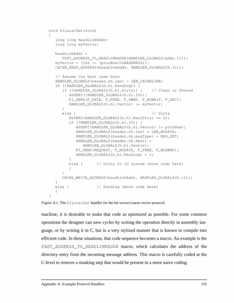
Appendix A: Example Protocol Handlers 155
machine, it is desirable to make that code as optimized as possible. For some common
operations the designer can save cycles by writing the operation directly in assembly lan-
guage, or by writing it in C, but in a very stylized manner that is known to compile into
efficient code. In those situations, that code sequence becomes a macro. An example is the
FAST_ADDRESS_TO_HEADLINKADDR macro, which calculates the address of the
directory entry from the incoming message address. This macro is carefully coded at the
C-level to remove a masking step that would be present in a more naive coding.
void PILocalGet(void) { long long headLinkAddr;
long long myVector;
headLinkAddr =FAST_ADDRESS_TO_HEADLINKADDR(HANDLER_GLOBALS(addr.ll));
myVector = (1LL << (procNum/COARSENESS)); CACHE_READ_ADDRESS(headLinkAddr, HANDLER_GLOBALS(h.ll));
// Assume the best case here HANDLER_GLOBALS(header.nh.len) = LEN_CACHELINE; if (!HANDLER_GLOBALS(h.hl.Pending)) { if (!HANDLER_GLOBALS(h.hl.Dirty)) { // Clean or Shared ASSERT(!HANDLER_GLOBALS(h.hl.IO));
PI_SEND(F_DATA, F_FREE, F_SWAP, F_NOWAIT, F_DEC); HANDLER_GLOBALS(h.hl.Vector) |= myVector;
} else { // Dirty
ASSERT(HANDLER_GLOBALS(h.hl.RealPtrs) == 0); if (!HANDLER_GLOBALS(h.hl.IO)) {
ASSERT(HANDLER_GLOBALS(h.hl.Vector) != procNum); HANDLER_GLOBALS(header.nh.len) = LEN_NODATA; HANDLER_GLOBALS(header.nh.msgType) = MSG_GET; HANDLER_GLOBALS(header.nh.dest) =
HANDLER_GLOBALS(h.hl.Vector); NI_SEND(REQUEST, F_NODATA, F_FREE, F_NOSWAP); HANDLER_GLOBALS(h.hl.Pending) = 1;
} else { // Dirty in IO system (more code here)}
}CACHE_WRITE_ADDRESS(headLinkAddr, HANDLER_GLOBALS(h.ll));
}else { // Pending (more code here)}
}
Figure A.1. The PILocalGet handler for the bit-vector/coarse-vector protocol.
Appendix A: Example Protocol Handlers 156
The PILocalGet handler is optimized for the common case where the cache line is clean
in main memory, or is shared by any number of other processors. In either of these cases,
main memory has a valid copy of the line, which is being fetched by a speculative read
from the inbox. The handler code begins by converting the message address into the
address of the directory entry, then reading the entry from the MAGIC data cache. The
result of the cache read is returned in a global register (hence HANDLER_GLOBALS)
reserved to hold the current directory entry. The remainder of the handler checks various
bits of the directory entry and then takes the appropriate action. In the best case, the line is
not Pending, nor is it Dirty. In this case the handler simply executes a PI_SEND, returning
the cache line to the processor. The send instruction in the protocol processor includes
various flags which are set inside the PI_SEND macro. In this case, these flags tell the
outbox that the message has data associated with it, that it should free the data buffer, and
that the PI should decrement its fence count register when the send is complete.
Note the use of ASSERT statements in the protocol handlers. Assertions can be used in
both C-handlers and PPsim handlers to ensure that the protocol is in a valid state. Asser-
tions are invaluable debugging tools, both in FlashLite and on the real hardware. In the
simulator, failed assertions cause the application to halt and dump useful state. For the real
hardware, assertions are typically not compiled into the protocol code for performance
reasons. However, assertions are extremely useful on the real machine when debugging
system failures.
In the bit-vector/coarse-vector protocol even the uncommon cases are fast. In the case
where the line is not Pending, but it is Dirty, the handler is only slightly more complicated.
In this case the handler has to send a MSG_GET request to the dirty node. To accomplish
this, the handler changes the message length, the message type, and the message destina-
tion, and then issues an NI_SEND. The NI_SEND macro has similar flags to the
PI_SEND macro, with the main differences being the addition of a lane flag, and the lack
of flags for control of interventions and the fence count. After the send, the handler sets
the Pending bit in the directory entry, and writes the entry back to the MAGIC data cache.
To really appreciate the efficiency of the bit-vector/coarse-vector protocol one needs to
see the final, scheduled protocol code for the real machine. Figure A.2 shows the same
portions of PILocalGet shown in Figure A.1. The critical path through the handler is
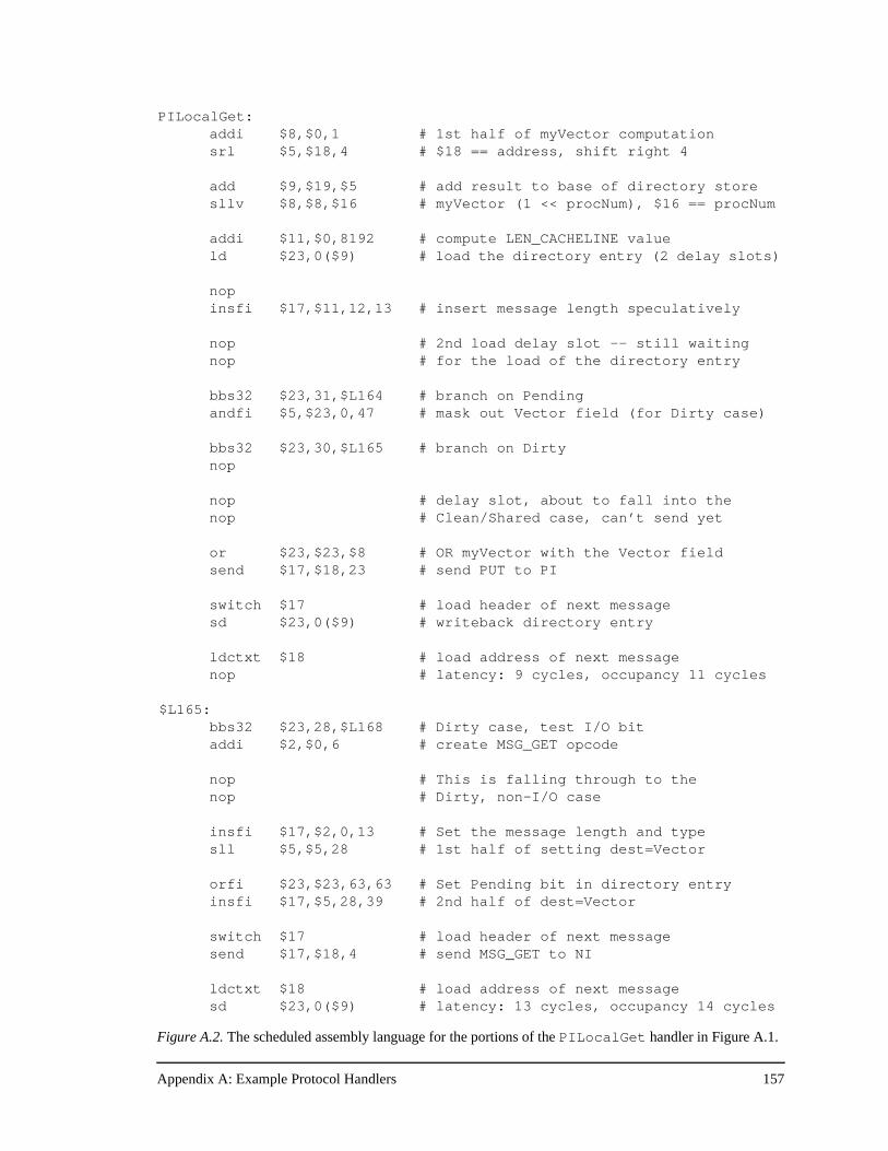
Appendix A: Example Protocol Handlers 157
PILocalGet:addi $8,$0,1 # 1st half of myVector computationsrl $5,$18,4 # $18 == address, shift right 4
add $9,$19,$5 # add result to base of directory storesllv $8,$8,$16 # myVector (1 << procNum), $16 == procNum
addi $11,$0,8192 # compute LEN_CACHELINE valueld $23,0($9) # load the directory entry (2 delay slots)
nopinsfi $17,$11,12,13 # insert message length speculatively
nop # 2nd load delay slot -- still waitingnop # for the load of the directory entry
bbs32 $23,31,$L164 # branch on Pendingandfi $5,$23,0,47 # mask out Vector field (for Dirty case)
bbs32 $23,30,$L165 # branch on Dirtynop
nop # delay slot, about to fall into thenop # Clean/Shared case, can’t send yet
or $23,$23,$8 # OR myVector with the Vector fieldsend $17,$18,23 # send PUT to PI
switch $17 # load header of next messagesd $23,0($9) # writeback directory entry
ldctxt $18 # load address of next messagenop # latency: 9 cycles, occupancy 11 cycles
$L165: bbs32 $23,28,$L168 # Dirty case, test I/O bitaddi $2,$0,6 # create MSG_GET opcode
nop # This is falling through to the nop # Dirty, non-I/O case
insfi $17,$2,0,13 # Set the message length and typesll $5,$5,28 # 1st half of setting dest=Vector
orfi $23,$23,63,63 # Set Pending bit in directory entryinsfi $17,$5,28,39 # 2nd half of dest=Vector
switch $17 # load header of next messagesend $17,$18,4 # send MSG_GET to NI
ldctxt $18 # load address of next messagesd $23,0($9) # latency: 13 cycles, occupancy 14 cycles
Figure A.2. The scheduled assembly language for the portions of the PILocalGet handler in Figure A.1.
Appendix A: Example Protocol Handlers 158
the loading of the directory entry and the branches on the possible states. The
FAST_ADDRESS_TO_HEADLINKADDR macro results in a 2-cycle sequence of shifting
the incoming address and adding it to a global register that is initialized to the base address
of the directory store. The CACHE_READ_ADDRESS macro results in the load of the
directory entry from the cache. Since loads have two delay slots in the protocol processor,
other potentially useful work is pushed up to make sure the common case is as fast as pos-
sible. The handler sets the length to LEN_CACHELINE, anticipating that the line will be
clean or shared in main memory.
The version of PILocalGet shown in Figure A.2 has a coarseness value of one.
When computing the bit-vector value to logically OR into the Vector field of the directory
entry, the protocol handler must divide the processor number by the coarseness value and
use that result as the amount to shift left a “1”. The protocol handler, however, does not
perform a division. Since coarseness is a power of two and is known at compile time, the
protocol handler simply performs a shift right. Furthermore, this does not impact the per-
formance of PILocalGet since the shift right adds only one additional instruction, and
there are many empty slots between the load of the directory entry and its eventual use.
Since all protocol handlers that read the directory entry have this same sequence of
instructions, having a coarseness value greater than one has very little impact on the direct
overhead of the bit-vector/coarse-vector protocol.
After the two load delay slots, the handler performs the branch tests for Pending and
Dirty in consecutive cycles. The protocol processor has squashing branches, meaning any
branch or jump in the delay slot of a taken branch is squashed, but other instructions are
always executed. The ability to execute branches in consecutive cycles is a critical feature
of the protocol processor, and one that helps to reduce request latency and protocol proces-
sor occupancy in branch-laden protocol code.
After the test against Dirty, the handler only needs to send a PUT message to the PI. The
handler must wait one cycle since the first cycle after the Dirty branch is in the delay slot
of the branch and any instructions there would be executed even if the branch were taken.
The handler does not need to set the message type to PUT because the encodings were
carefully chosen so that the incoming GET message from the PI has the same encoding as
Appendix A: Example Protocol Handlers 159
the outgoing PUT message. So, in the ninth instruction packet, PILocalGet sends its
result to the PI.
If protocol processor latency is defined as the number of cycles to the first send
instruction, PILocalGet has a latency of 9 cycles in this case. However, the handler has
not yet run to completion. The setting of the Vector field, and the writeback of the direc-
tory entry take an additional two cycles. If protocol processor occupancy is defined as the
number of cycles from the start of the handler to the end, PILocalGet has an occupancy
of 11 cycles in this case.
A.2 Dynamic Pointer Allocation Handlers
Figure A.3 shows the same two cases for the PILocalGet handler that were shown in
Figure A.1. Because of the Local bit in the directory header, there is very little difference
between this code and the bit-vector/coarse-vector code for this handler. A more illustra-
tive handler is the NILocalGet handler, responsible for handling remote read misses.
The C code for the most common case, where the cache line is either clean at the home or
shared by some number of processors, is shown in Figure A.4.
Since NILocalGet must read the directory entry, it begins the same way PILocal-
Get begins, by converting the address in the message into the address for the directory
entry, and reading the directory entry through the MAGIC data cache. Again, the handler
is optimized for the common case and the message type and length are speculatively set so
that they are correct for returning a cache line of data to the requester. After similar checks
against the Pending and Dirty bits, the code diverges from its bit-vector/coarse-vector
counterpart. Because dynamic pointer allocation maintains the first remote sharer in the
directory header, the NILocalGet routine must check the HeadPtr bit to see if there is
already a valid sharer in that location. If HeadPtr is not set, then the protocol handler sends
the expected MSG_PUT response to the requester, inserts the requester (the src field in the
message) into the Ptr position in the directory header, sets the HeadPtr bit to valid, and
writes back the directory header.
If HeadPtr is already set, then the protocol handler must use the pointer/link store and
add an element to the linked list of sharers. This is the job of the EnqueueNewSharer
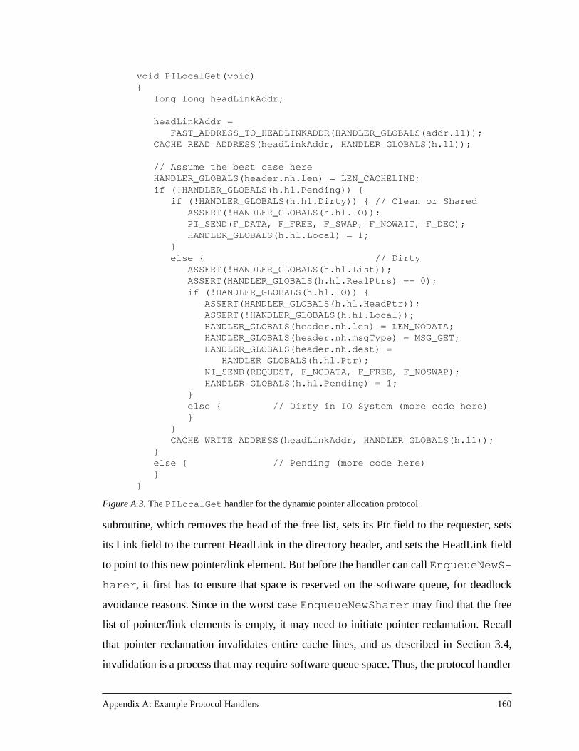
Appendix A: Example Protocol Handlers 160
subroutine, which removes the head of the free list, sets its Ptr field to the requester, sets
its Link field to the current HeadLink in the directory header, and sets the HeadLink field
to point to this new pointer/link element. But before the handler can call EnqueueNewS-
harer, it first has to ensure that space is reserved on the software queue, for deadlock
avoidance reasons. Since in the worst case EnqueueNewSharer may find that the free
list of pointer/link elements is empty, it may need to initiate pointer reclamation. Recall
that pointer reclamation invalidates entire cache lines, and as described in Section 3.4,
invalidation is a process that may require software queue space. Thus, the protocol handler
void PILocalGet(void) { long long headLinkAddr;
headLinkAddr = FAST_ADDRESS_TO_HEADLINKADDR(HANDLER_GLOBALS(addr.ll));
CACHE_READ_ADDRESS(headLinkAddr, HANDLER_GLOBALS(h.ll));
// Assume the best case here HANDLER_GLOBALS(header.nh.len) = LEN_CACHELINE; if (!HANDLER_GLOBALS(h.hl.Pending)) { if (!HANDLER_GLOBALS(h.hl.Dirty)) { // Clean or Shared ASSERT(!HANDLER_GLOBALS(h.hl.IO));
PI_SEND(F_DATA, F_FREE, F_SWAP, F_NOWAIT, F_DEC); HANDLER_GLOBALS(h.hl.Local) = 1;
} else { // Dirty ASSERT(!HANDLER_GLOBALS(h.hl.List)); ASSERT(HANDLER_GLOBALS(h.hl.RealPtrs) == 0);
if (!HANDLER_GLOBALS(h.hl.IO)) { ASSERT(HANDLER_GLOBALS(h.hl.HeadPtr)); ASSERT(!HANDLER_GLOBALS(h.hl.Local)); HANDLER_GLOBALS(header.nh.len) = LEN_NODATA; HANDLER_GLOBALS(header.nh.msgType) = MSG_GET; HANDLER_GLOBALS(header.nh.dest) =
HANDLER_GLOBALS(h.hl.Ptr); NI_SEND(REQUEST, F_NODATA, F_FREE, F_NOSWAP); HANDLER_GLOBALS(h.hl.Pending) = 1;
} else { // Dirty in IO System (more code here)}
}CACHE_WRITE_ADDRESS(headLinkAddr, HANDLER_GLOBALS(h.ll));
}else { // Pending (more code here)}
}
Figure A.3. The PILocalGet handler for the dynamic pointer allocation protocol.
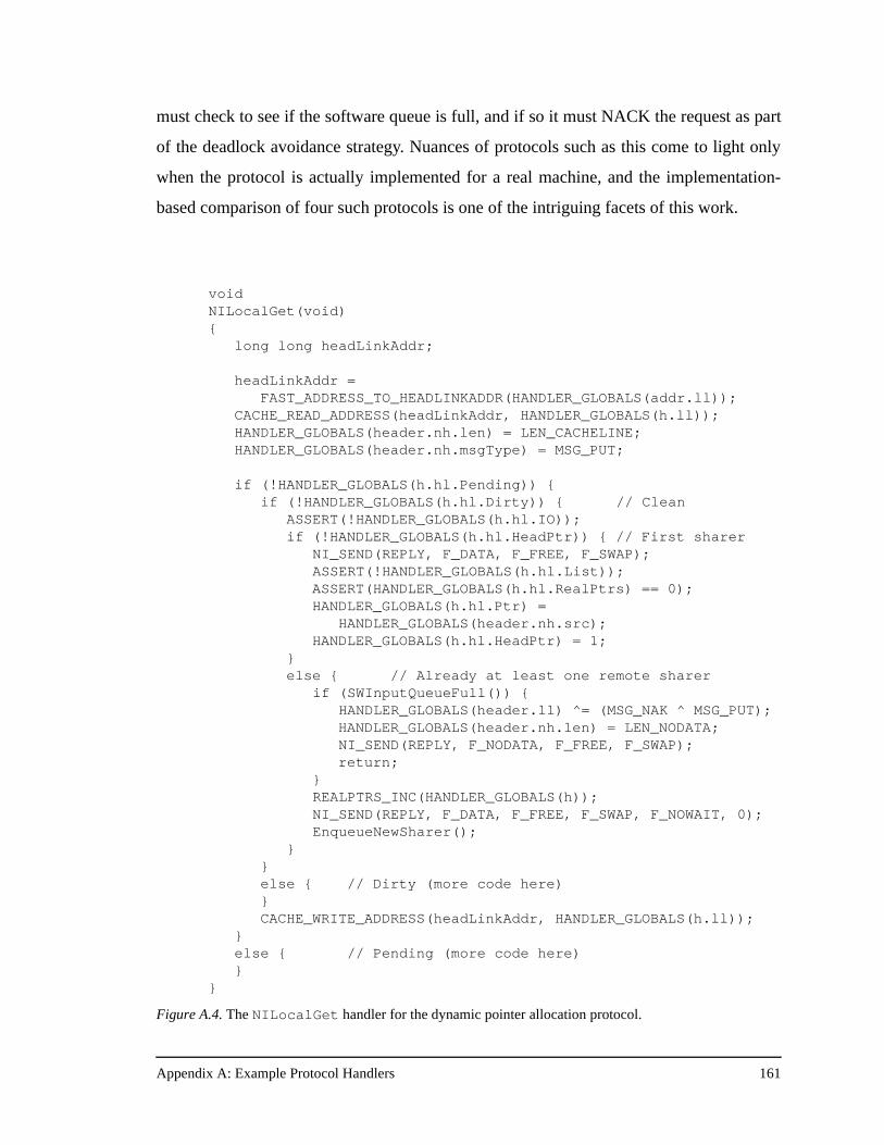
Appendix A: Example Protocol Handlers 161
must check to see if the software queue is full, and if so it must NACK the request as part
of the deadlock avoidance strategy. Nuances of protocols such as this come to light only
when the protocol is actually implemented for a real machine, and the implementation-
based comparison of four such protocols is one of the intriguing facets of this work.
void NILocalGet(void) {
long long headLinkAddr;
headLinkAddr = FAST_ADDRESS_TO_HEADLINKADDR(HANDLER_GLOBALS(addr.ll));
CACHE_READ_ADDRESS(headLinkAddr, HANDLER_GLOBALS(h.ll)); HANDLER_GLOBALS(header.nh.len) = LEN_CACHELINE; HANDLER_GLOBALS(header.nh.msgType) = MSG_PUT;
if (!HANDLER_GLOBALS(h.hl.Pending)) { if (!HANDLER_GLOBALS(h.hl.Dirty)) { // Clean
ASSERT(!HANDLER_GLOBALS(h.hl.IO)); if (!HANDLER_GLOBALS(h.hl.HeadPtr)) { // First sharer
NI_SEND(REPLY, F_DATA, F_FREE, F_SWAP); ASSERT(!HANDLER_GLOBALS(h.hl.List));
ASSERT(HANDLER_GLOBALS(h.hl.RealPtrs) == 0); HANDLER_GLOBALS(h.hl.Ptr) =
HANDLER_GLOBALS(header.nh.src); HANDLER_GLOBALS(h.hl.HeadPtr) = 1;
} else { // Already at least one remote sharer
if (SWInputQueueFull()) { HANDLER_GLOBALS(header.ll) ^= (MSG_NAK ^ MSG_PUT);
HANDLER_GLOBALS(header.nh.len) = LEN_NODATA; NI_SEND(REPLY, F_NODATA, F_FREE, F_SWAP);
return; }
REALPTRS_INC(HANDLER_GLOBALS(h)); NI_SEND(REPLY, F_DATA, F_FREE, F_SWAP, F_NOWAIT, 0); EnqueueNewSharer();
} } else { // Dirty (more code here)
}CACHE_WRITE_ADDRESS(headLinkAddr, HANDLER_GLOBALS(h.ll));
}else { // Pending (more code here)}
}
Figure A.4. The NILocalGet handler for the dynamic pointer allocation protocol.
Appendix A: Example Protocol Handlers 162
A.3 SCI Handlers
Unlike the previous two protocols, SCI keeps protocol state at the requester, in the form
of the duplicate set of tags and the replacement buffer. Both SCI and the previous proto-
cols keep protocol state at the home node, in the form of the directory entries. Keeping
state at the requester can be advantageous in terms of better distributing the load in the
memory system, but it can also impose a performance penalty when remote requests des-
tined for the home node must first check the local state before issuing into the network.
For example, in the previous two protocols the PIRemoteGet handler that is dispatched
for remote cache read misses has a latency of 3 protocol processor cycles. The same han-
dler in the SCI protocol has a latency of 13 protocol processor cycles.
Figure A.5 shows the C-version of the SCI PIRemoteGet handler. The common path
through the handler first checks that there is room in the replacement buffer, ensures that
this particular address is not already in the hash table, and then forwards the read request
on to the home node. These actions incur a protocol processor latency of 13 cycles. The
PIRemoteGet handler is nowhere near completed, however. There is a final call to
RolloutDuplicateTags which handles the duplicate tags data structure manipula-
tions. The old cache line is copied out of the duplicate tags structure, and the newly
accessed cache line is inserted in its place. Then, based on the state of the old cache line, a
distributed roll out transaction may be initiated. If so, the entire data structure is placed in
a replacement buffer and entered into the hash table so that the roll out may complete at
some point in the future. All of this duplicate tag manipulation takes time and therefore
consumes protocol processor cycles. Note that this roll out process is not affecting the
latency of the request since the cache miss was forwarded on to the home node before the
roll out procedure began. This process does, however, have an impact on protocol proces-
sor occupancy. The protocol processor is tied up handling the duplicate tag structure and
cannot handle additional requests until the handler completes.
The issue of increased protocol processor occupancy is at the core of the SCI results
presented in Chapter 6. Interestingly, the occupancy news for SCI is not all bad. Specifi-
cally, SCI only occurs large occupancies at the requester (for the PI handlers). These are
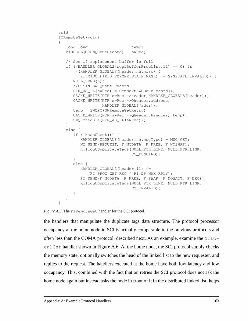
Appendix A: Example Protocol Handlers 163
the handlers that manipulate the duplicate tags data structure. The protocol processor
occupancy at the home node in SCI is actually comparable to the previous protocols and
often less than the COMA protocol, described next. As an example, examine the NILo-
calGet handler shown in Figure A.6. At the home node, the SCI protocol simply checks
the memory state, optionally switches the head of the linked list to the new requester, and
replies to the request. The handlers executed at the home have both low latency and low
occupancy. This, combined with the fact that on retries the SCI protocol does not ask the
home node again but instead asks the node in front of it in the distributed linked list, helps
void PIRemoteGet(void) { long long temp; PTRDECL(CCSWQueueRecord) swRec;
// See if replacement buffer is full if ((HANDLER_GLOBALS(replBufferFreeList.ll) == 0) && ((HANDLER_GLOBALS(header.nh.misc) &
PI_MISC_FIELD_FORMER_STATE_MASK) != SYSSTATE_INVALID)) { NULL_SEND(5);
//Build SW Queue Record PTR_AS_LL(swRec) = GetNextSWQueueRecord(); CACHE_WRITE(PTR(swRec)->header,HANDLER_GLOBALS(header)); CACHE_WRITE(PTR(swRec)->Qheader.address, HANDLER_GLOBALS(addr)); temp = SWQPC(SWRemoteGetRetry); CACHE_WRITE(PTR(swRec)->Qheader.handler, temp); SWQSchedule(PTR_AS_LL(swRec)); } else { if (!HashCheck()) { HANDLER_GLOBALS(header.nh.msgType) = MSG_GET;
NI_SEND(REQUEST, F_NODATA, F_FREE, F_NOSWAP); RolloutDuplicateTags(NULL_PTR_LINK, NULL_PTR_LINK,
CS_PENDING); } else {
HANDLER_GLOBALS(header.ll) ^= (PI_PROC_GET_REQ ^ PI_DP_NAK_RPLY);
PI_SEND(F_NODATA, F_FREE, F_SWAP, F_NOWAIT, F_DEC); RolloutDuplicateTags(NULL_PTR_LINK, NULL_PTR_LINK,
CS_INVALID); } } }
Figure A.5. The PIRemoteGet handler for the SCI protocol.
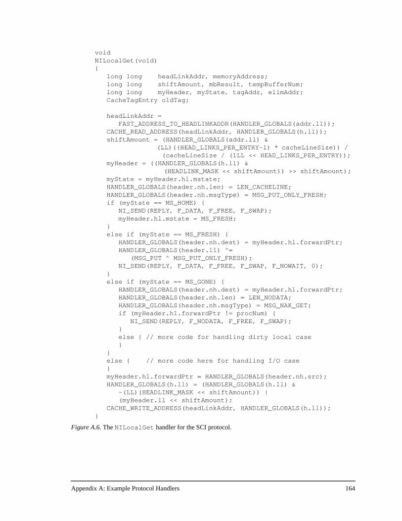
Appendix A: Example Protocol Handlers 164
void NILocalGet(void) {
long long headLinkAddr, memoryAddress; long long shiftAmount, mbResult, tempBufferNum; long long myHeader, myState, tagAddr, elimAddr; CacheTagEntry oldTag;
headLinkAddr = FAST_ADDRESS_TO_HEADLINKADDR(HANDLER_GLOBALS(addr.ll));
CACHE_READ_ADDRESS(headLinkAddr, HANDLER_GLOBALS(h.ll)); shiftAmount = (HANDLER_GLOBALS(addr.ll) &
(LL)((HEAD_LINKS_PER_ENTRY-1) * cacheLineSize)) / (cacheLineSize / (1LL << HEAD_LINKS_PER_ENTRY));
myHeader = ((HANDLER_GLOBALS(h.ll) & (HEADLINK_MASK << shiftAmount)) >> shiftAmount);
myState = myHeader.hl.mstate; HANDLER_GLOBALS(header.nh.len) = LEN_CACHELINE;
HANDLER_GLOBALS(header.nh.msgType) = MSG_PUT_ONLY_FRESH; if (myState == MS_HOME) {
NI_SEND(REPLY, F_DATA, F_FREE, F_SWAP); myHeader.hl.mstate = MS_FRESH;
} else if (myState == MS_FRESH) {
HANDLER_GLOBALS(header.nh.dest) = myHeader.hl.forwardPtr; HANDLER_GLOBALS(header.ll) ^=
(MSG_PUT ^ MSG_PUT_ONLY_FRESH); NI_SEND(REPLY, F_DATA, F_FREE, F_SWAP, F_NOWAIT, 0); } else if (myState == MS_GONE) {
HANDLER_GLOBALS(header.nh.dest) = myHeader.hl.forwardPtr; HANDLER_GLOBALS(header.nh.len) = LEN_NODATA;
HANDLER_GLOBALS(header.nh.msgType) = MSG_NAK_GET; if (myHeader.hl.forwardPtr != procNum) { NI_SEND(REPLY, F_NODATA, F_FREE, F_SWAP); } else { // more code for handling dirty local case
}}else { // more code here for handling I/O case} myHeader.hl.forwardPtr = HANDLER_GLOBALS(header.nh.src); HANDLER_GLOBALS(h.ll) = (HANDLER_GLOBALS(h.ll) &
~(LL)(HEADLINK_MASK << shiftAmount)) | (myHeader.ll << shiftAmount);
CACHE_WRITE_ADDRESS(headLinkAddr, HANDLER_GLOBALS(h.ll));}
Figure A.6. The NILocalGet handler for the SCI protocol.
Appendix A: Example Protocol Handlers 165
distribute the message traffic more evenly throughout the machine and can improve over-
all performance when there is significant hot-spotting in the memory system of large
machines.
A.4 COMA Handlers
The protocol handlers that are most different in COMA are the handlers for remote
cache misses. COMA, like SCI, has remote miss handlers that check protocol state at the
requester, while in bit-vector/coarse-vector and dynamic pointer allocation remote misses
are simply forwarded to the home node. COMA also has more work to do on the data
reply handlers, since it must send the data both to the processor and the attraction memory,
maintain the attraction memory tags and state, and handle any attraction memory displace-
ments generated by the data reply. In the previous protocols, these data reply handlers are
among the shortest in terms of both protocol processor latency and occupancy. In COMA,
the latencies are still low since the handlers immediately send the data to the processor,
but the occupancies are much higher. Example protocol handlers for each of these two
cases are discussed below.
Figure A.7 shows the COMA PIRemoteGet handler, which is responsible for han-
dling processor cache read misses to remote cache lines. This handler begins exactly like
the PILocalGet handler in COMA and the other protocols, since COMA is assuming
the line is gong to be in the local attraction memory even though it is a remote address.
After reading the directory header, the handler compares the tag in the directory entry with
the tag of the cache miss address. If the tags match, then it is an AM hit, and the handler
simply responds with the data from the speculative read initiated by the inbox. This is the
good case for COMA since it just responded to a remote read miss in 10 cycles, over 8
times faster than a remote read miss in the previous protocols.
If the tags do not match, then the PIRemoteGet handler suffers an AM miss, and the
line is forwarded to the home just as in the previous protocols. It is clear from this handler
why it is important that conflict or capacity misses dominate if COMA wants to achieve
good performance. In those cases, remote data is likely to be found in the attraction mem-
ory and therefore fall into the AM hit case above. But if cold misses or coherence misses
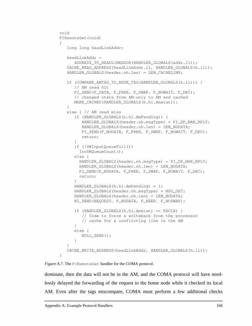
Appendix A: Example Protocol Handlers 166
dominate, then the data will not be in the AM, and the COMA protocol will have need-
lessly delayed the forwarding of the request to the home node while it checked its local
AM. Even after the tags miscompare, COMA must perform a few additional checks
void PIRemoteGet(void) { long long headLinkAddr;
headLinkAddr = ADDRESS_TO_HEADLINKADDR(HANDLER_GLOBALS(addr.ll));
CACHE_READ_ADDRESS(headLinkAddr.ll, HANDLER_GLOBALS(h.ll)); HANDLER_GLOBALS(header.nh.len) = LEN_CACHELINE;
if (COMPARE_AMTAG_TO_ADDR_TAG(HANDLER_GLOBALS(h.ll))) { // AM read hitPI_SEND(F_DATA, F_FREE, F_SWAP, F_NOWAIT, F_DEC); // changed state from AM-only to AM and cached
MAKE_CACHED(HANDLER_GLOBALS(h.hl.Amstat)); }else { // AM read miss
if (HANDLER_GLOBALS(h.hl.AmPending)) { HANDLER_GLOBALS(header.nh.msgType) = PI_DP_NAK_RPLY;
HANDLER_GLOBALS(header.nh.len) = LEN_NODATA; PI_SEND(F_NODATA, F_FREE, F_SWAP, F_NOWAIT, F_DEC);
return; }
if (!SWInputQueueFull()) IncSWQueueCount(); else {
HANDLER_GLOBALS(header.nh.msgType) = PI_DP_NAK_RPLY; HANDLER_GLOBALS(header.nh.len) = LEN_NODATA;
PI_SEND(F_NODATA, F_FREE, F_SWAP, F_NOWAIT, F_DEC); return; }
HANDLER_GLOBALS(h.hl.AmPending) = 1; HANDLER_GLOBALS(header.nh.msgType) = MSG_GET;
HANDLER_GLOBALS(header.nh.len) = LEN_NODATA; NI_SEND(REQUEST, F_NODATA, F_KEEP, F_NOSWAP);
if (HANDLER_GLOBALS(h.hl.Amstat) == EXCLX) { // Code to force a writeback from the processor// cache for a conflicting line in the AM
}else {
NULL_SEND(); }
}CACHE_WRITE_ADDRESS(headLinkAddr, HANDLER_GLOBALS(h.ll));
}
Figure A.7. The PIRemoteGet handler for the COMA protocol.
Appendix A: Example Protocol Handlers 167
before forwarding the request to the home node. Similar to the replacement buffer in SCI,
COMA needs to check to ensure that there is no other outstanding transaction on that par-
ticular AM line. COMA must also check for software queue space because it may need
that software queue space in the eventual data reply handler. If either of these conditions is
not met, the handler must NACK the request back to the processor rather than forwarding
it to the home. The end result for a read miss that goes remote is a PIRemoteGet latency
of 16 cycles, as compared to 3 cycles in the bit-vector/coarse-vector protocol.
An example of a COMA data reply handler is NIRemotePut, shown in Figure A.8.
The very first instruction of the handler is a send to the processor interface, so the han-
dler has a latency of only one cycle. However, the remainder of the handler deals with put-
ting the data into the AM and the possible displacement of an attraction memory line to
make room for the new data reply. The displacement process is very involved and depends
first on whether this PUT message is from the master or not, and then on the particular
AM state of the line being replaced. The handler must check the AM state and then based
on the state issue either a replace or replace exclusive message. Because this is the NIRe-
motePut handler and MSG_PUT is a reply, the deadlock avoidance rules do not allow
this handler to send any outgoing network messages. Unfortunately, that is precisely what
it has to do in the AM displacement case. The software queue bails out the protocol in this
case, since software queue space was reserved initially by the PIRemoteGet handler as
shown in Figure A.7. Still, after NIRemotePut decides it needs to replace the line, it
incurs extra overhead because it has to check the outgoing queue request space and pro-
ceed if there is enough space to send the replacement message, or suspend to the software
queue if there is not enough outgoing queue space.
In addition, the NIRemotePut handler is sending these replacement messages with
data, unlike the replacement hint messages in the dynamic pointer allocation protocol. To
get the data, the handler must first allocate a new data buffer, since the one with the origi-
nal data reply is being used to send the data back to the processor. Once a buffer has been
allocated, the handler must initiate a memory read to load the contents of the AM line
being displaced. Once the read is initiated, the handler can issue the send to the network
and finish up the state manipulations. The remaining bookkeeping is the changing of the
AM tag to the tag for the new data reply, setting the new AM state appropriately, decre-
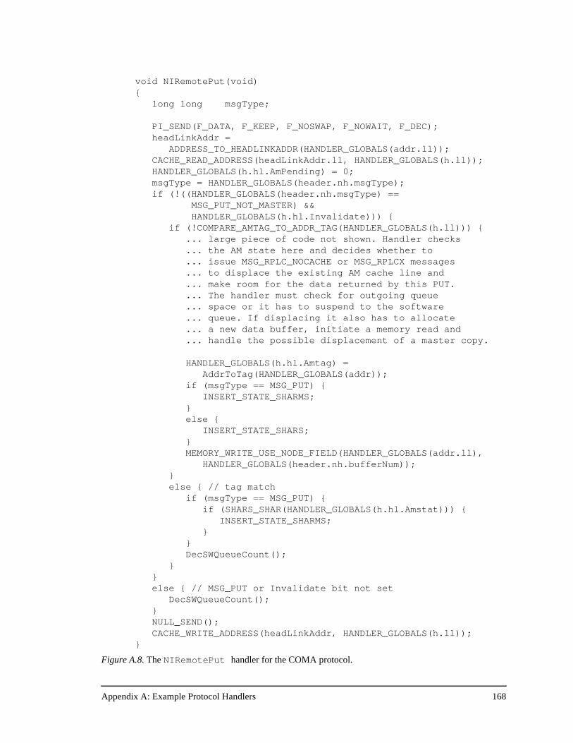
Appendix A: Example Protocol Handlers 168
void NIRemotePut(void) {
long long msgType;
PI_SEND(F_DATA, F_KEEP, F_NOSWAP, F_NOWAIT, F_DEC); headLinkAddr =
ADDRESS_TO_HEADLINKADDR(HANDLER_GLOBALS(addr.ll)); CACHE_READ_ADDRESS(headLinkAddr.ll, HANDLER_GLOBALS(h.ll)); HANDLER_GLOBALS(h.hl.AmPending) = 0; msgType = HANDLER_GLOBALS(header.nh.msgType);if (!((HANDLER_GLOBALS(header.nh.msgType) ==
MSG_PUT_NOT_MASTER) && HANDLER_GLOBALS(h.hl.Invalidate))) {
if (!COMPARE_AMTAG_TO_ADDR_TAG(HANDLER_GLOBALS(h.ll))) { ... large piece of code not shown. Handler checks ... the AM state here and decides whether to ... issue MSG_RPLC_NOCACHE or MSG_RPLCX messages... to displace the existing AM cache line and... make room for the data returned by this PUT.... The handler must check for outgoing queue... space or it has to suspend to the software... queue. If displacing it also has to allocate... a new data buffer, initiate a memory read and... handle the possible displacement of a master copy.
HANDLER_GLOBALS(h.hl.Amtag) = AddrToTag(HANDLER_GLOBALS(addr));
if (msgType == MSG_PUT) { INSERT_STATE_SHARMS;
} else {
INSERT_STATE_SHARS; } MEMORY_WRITE_USE_NODE_FIELD(HANDLER_GLOBALS(addr.ll),
HANDLER_GLOBALS(header.nh.bufferNum)); } else { // tag match
if (msgType == MSG_PUT) { if (SHARS_SHAR(HANDLER_GLOBALS(h.hl.Amstat))) {
INSERT_STATE_SHARMS; } }
DecSWQueueCount(); }
} else { // MSG_PUT or Invalidate bit not set
DecSWQueueCount(); } NULL_SEND();
CACHE_WRITE_ADDRESS(headLinkAddr, HANDLER_GLOBALS(h.ll)); }
Figure A.8. The NIRemotePut handler for the COMA protocol.
Appendix A: Example Protocol Handlers 169
menting the software queue count (and therefore freeing the slot), and freeing the data
buffer. This extra protocol overhead only affects the occupancy of the handler, but it can
be significant. While these handlers have occupancies of 3 cycles in the bit-vector/coarse-
vector and dynamic pointer allocation protocols, the NIRemotePut occupancy for the
COMA protocol is typically about 48 protocol processor cycles.
COMA’s higher latency in the remote processor interface handlers (like PIRemote-
Get), and its higher occupancies for network interface handlers, both at the home (not
shown) and on data replies (like NIRemotePut), result in much high direct protocol
overhead than the previous protocols. Still, COMA may achieve better performance if the
AM hit rate is high enough. This trade-off is at the heart of the COMA results presented in
Chapter 6.
Appendix B: Table of Results 170
Appendix B
Table of Results
This appendix includes Table B.1., the full table of results of the experiments described
in Chapter 5, from which selected results were given in detail in Chapter 6. For each appli-
cation, each protocol, and each processor count, the table records the execution time (Ex),
the parallel efficiency (PE), and the message overhead (MO). The execution time and the
message overhead are normalized to the bit-vector/coarse-vector protocol.
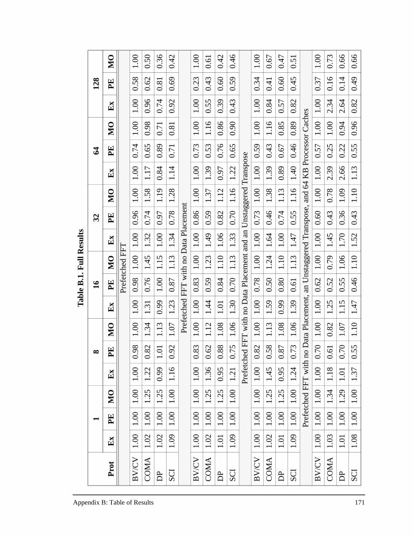
Appendix B: Table of Results 171
Tab
le B
.1. F
ull R
esul
ts
18
1632
6412
8
Pro
tE
xP
EM
OE
xP
EM
OE
xP
EM
OE
xP
EM
OE
xP
EM
OE
xP
EM
O
Pref
etch
ed F
FT
BV
/CV
1.00
1.00
1.00
1.00
0.98
1.00
1.00
0.98
1.00
1.00
0.96
1.00
1.00
0.74
1.00
1.00
0.58
1.00
CO
MA
1.02
1.00
1.25
1.22
0.82
1.34
1.31
0.76
1.45
1.32
0.74
1.58
1.17
0.65
0.98
0.96
0.62
0.50
DP
1.02
1.00
1.25
0.99
1.01
1.13
0.99
1.00
1.15
1.00
0.97
1.19
0.84
0.89
0.71
0.74
0.81
0.36
SCI
1.09
1.00
1.00
1.16
0.92
1.07
1.23
0.87
1.13
1.34
0.78
1.28
1.14
0.71
0.81
0.92
0.69
0.42
Pref
etch
ed F
FT
with
no
Dat
a Pl
acem
ent
BV
/CV
1.00
1.00
1.00
1.00
0.83
1.00
1.00
0.83
1.00
1.00
0.86
1.00
1.00
0.73
1.00
1.00
0.23
1.00
CO
MA
1.02
1.00
1.25
1.36
0.62
1.12
1.44
0.59
1.23
1.49
0.59
1.37
1.39
0.53
1.16
0.55
0.43
0.61
DP
1.01
1.00
1.25
0.95
0.88
1.08
1.01
0.84
1.10
1.06
0.82
1.12
0.97
0.76
0.86
0.39
0.60
0.42
SCI
1.09
1.00
1.00
1.21
0.75
1.06
1.30
0.70
1.13
1.33
0.70
1.16
1.22
0.65
0.90
0.43
0.59
0.46
Pref
etch
ed F
FT w
ith n
o D
ata
Plac
emen
t and
an
Uns
tagg
ered
Tra
nspo
se
BV
/CV
1.00
1.00
1.00
1.00
0.82
1.00
1.00
0.78
1.00
1.00
0.73
1.00
1.00
0.59
1.00
1.00
0.34
1.00
CO
MA
1.02
1.00
1.25
1.45
0.58
1.13
1.59
0.50
1.24
1.64
0.46
1.38
1.39
0.43
1.16
0.84
0.41
0.67
DP
1.01
1.00
1.25
0.95
0.87
1.08
0.99
0.80
1.10
1.00
0.74
1.13
0.89
0.67
0.85
0.57
0.60
0.47
SCI
1.09
1.00
1.00
1.24
0.73
1.06
1.39
0.61
1.13
1.47
0.55
1.16
1.40
0.46
0.89
0.82
0.45
0.51
Pref
etch
ed F
FT w
ith n
o D
ata
Plac
emen
t, an
Uns
tagg
ered
Tra
nspo
se, a
nd 6
4K
B P
roce
ssor
Cac
hes
BV
/CV
1.00
1.00
1.00
1.00
0.70
1.00
1.00
0.62
1.00
1.00
0.60
1.00
1.00
0.57
1.00
1.00
0.37
1.00
CO
MA
1.03
1.00
1.34
1.18
0.61
0.82
1.25
0.52
0.79
1.45
0.43
0.78
2.39
0.25
1.00
2.34
0.16
0.73
DP
1.01
1.00
1.29
1.01
0.70
1.07
1.15
0.55
1.06
1.70
0.36
1.09
2.66
0.22
0.94
2.64
0.14
0.66
SCI
1.08
1.00
1.00
1.37
0.55
1.10
1.47
0.46
1.10
1.52
0.43
1.10
1.13
0.55
0.96
0.82
0.49
0.66
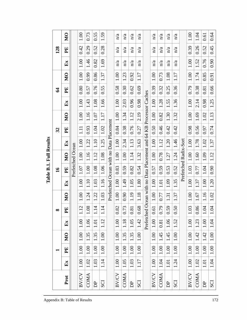
Appendix B: Table of Results 172
Tab
le B
.1. F
ull R
esul
ts
18
1632
6412
8
Pro
tE
xP
EM
OE
xP
EM
OE
xP
EM
OE
xP
EM
OE
xP
EM
OE
xP
EM
O
Pre
fetc
hed
Oce
an
BV
/CV
1.00
1.00
1.00
1.00
1.12
1.00
1.00
1.07
1.00
1.00
1.11
1.00
1.00
0.80
1.00
1.00
0.42
1.00
CO
MA
1.02
1.00
1.35
1.06
1.08
1.24
1.10
1.00
1.16
1.22
0.93
1.16
1.43
0.57
0.99
1.46
0.29
0.73
DP
1.03
1.00
1.35
1.01
1.14
1.22
1.03
1.08
1.12
1.10
1.04
1.07
1.08
0.76
0.86
0.82
0.52
0.55
SCI
1.14
1.00
1.00
1.12
1.14
1.03
1.16
1.06
1.08
1.25
1.02
1.17
1.66
0.55
1.37
1.69
0.28
1.59
Pref
etch
ed O
cean
with
no
Dat
a Pl
acem
ent
BV
/CV
1.00
1.00
1.00
1.00
0.82
1.00
1.00
0.83
1.00
1.00
0.84
1.00
1.00
0.58
1.00
n/a
n/a
n/a
CO
MA
1.05
1.00
1.35
1.18
0.73
0.90
1.49
0.59
1.00
2.34
0.38
1.34
2.03
0.30
1.23
n/a
n/a
n/a
DP
1.03
1.00
1.35
1.05
0.81
1.19
1.05
0.82
1.14
1.13
0.76
1.12
0.96
0.62
0.92
n/a
n/a
n/a
SCI
1.17
1.00
1.00
1.42
0.68
1.18
1.80
0.54
1.32
3.63
0.27
2.19
0.98
0.69
1.17
n/a
n/a
n/a
Pref
etch
ed O
cean
with
no
Dat
a Pl
acem
ent a
nd 6
4K
B P
roce
ssor
Cac
hes
BV
/CV
1.00
1.00
1.00
1.00
0.61
1.00
1.00
0.57
1.00
1.00
0.50
1.00
1.00
0.39
1.00
n/a
n/a
n/a
CO
MA
1.04
1.00
1.45
0.81
0.79
0.77
1.01
0.59
0.78
1.12
0.46
0.82
1.28
0.32
0.73
n/a
n/a
n/a
DP
1.01
1.00
1.45
1.06
0.59
1.31
1.09
0.53
1.27
1.20
0.42
1.30
1.55
0.25
1.08
n/a
n/a
n/a
SCI
1.24
1.00
1.00
1.52
0.50
1.37
1.35
0.52
1.24
1.46
0.42
1.32
1.36
0.36
1.17
n/a
n/a
n/a
Pref
etch
ed R
adix
-Sor
t
BV
/CV
1.00
1.00
1.00
1.00
1.03
1.00
1.00
1.03
1.00
1.00
0.98
1.00
1.00
0.79
1.00
1.00
0.39
1.00
CO
MA
1.02
1.00
1.42
1.23
0.86
1.67
1.37
0.77
1.60
1.78
0.56
1.69
2.14
0.38
1.74
1.52
0.26
1.04
DP
1.01
1.00
1.42
1.00
1.04
1.16
1.00
1.04
1.09
1.02
0.97
1.02
0.98
0.81
0.85
0.76
0.52
0.61
SCI
1.04
1.00
1.00
1.04
1.04
1.02
1.20
0.90
1.12
1.37
0.74
1.13
1.25
0.66
0.91
0.90
0.45
0.64
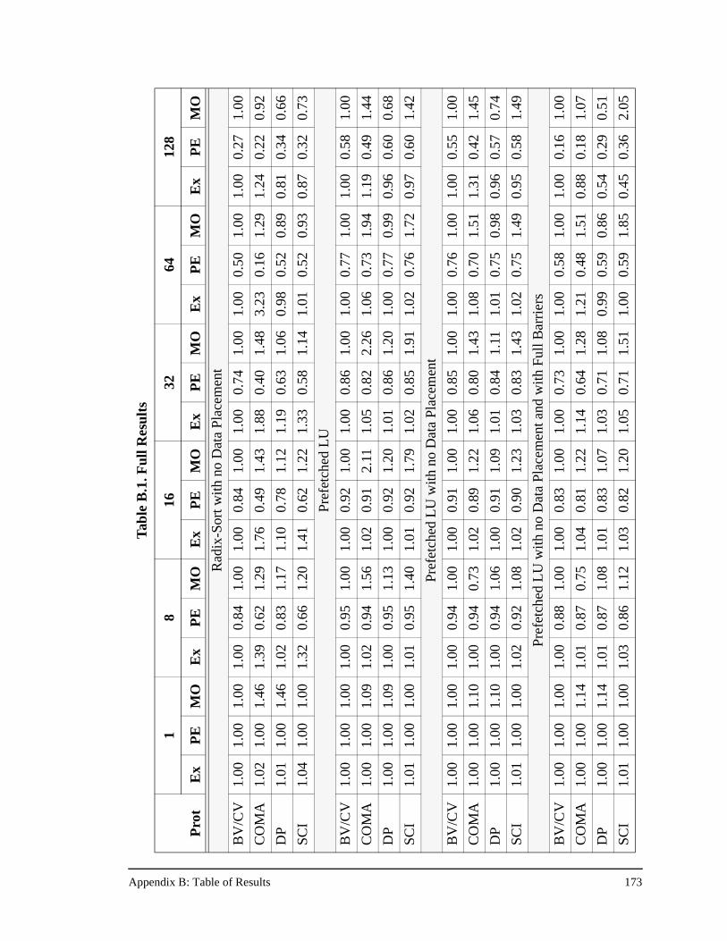
Appendix B: Table of Results 173
Tab
le B
.1. F
ull R
esul
ts
18
1632
6412
8
Pro
tE
xP
EM
OE
xP
EM
OE
xP
EM
OE
xP
EM
OE
xP
EM
OE
xP
EM
O
Rad
ix-S
ort w
ith n
o D
ata
Plac
emen
t
BV
/CV
1.00
1.00
1.00
1.00
0.84
1.00
1.00
0.84
1.00
1.00
0.74
1.00
1.00
0.50
1.00
1.00
0.27
1.00
CO
MA
1.02
1.00
1.46
1.39
0.62
1.29
1.76
0.49
1.43
1.88
0.40
1.48
3.23
0.16
1.29
1.24
0.22
0.92
DP
1.01
1.00
1.46
1.02
0.83
1.17
1.10
0.78
1.12
1.19
0.63
1.06
0.98
0.52
0.89
0.81
0.34
0.66
SCI
1.04
1.00
1.00
1.32
0.66
1.20
1.41
0.62
1.22
1.33
0.58
1.14
1.01
0.52
0.93
0.87
0.32
0.73
Pre
fetc
hed
LU
BV
/CV
1.00
1.00
1.00
1.00
0.95
1.00
1.00
0.92
1.00
1.00
0.86
1.00
1.00
0.77
1.00
1.00
0.58
1.00
CO
MA
1.00
1.00
1.09
1.02
0.94
1.56
1.02
0.91
2.11
1.05
0.82
2.26
1.06
0.73
1.94
1.19
0.49
1.44
DP
1.00
1.00
1.09
1.00
0.95
1.13
1.00
0.92
1.20
1.01
0.86
1.20
1.00
0.77
0.99
0.96
0.60
0.68
SCI
1.01
1.00
1.00
1.01
0.95
1.40
1.01
0.92
1.79
1.02
0.85
1.91
1.02
0.76
1.72
0.97
0.60
1.42
Pref
etch
ed L
U w
ith n
o D
ata
Plac
emen
t
BV
/CV
1.00
1.00
1.00
1.00
0.94
1.00
1.00
0.91
1.00
1.00
0.85
1.00
1.00
0.76
1.00
1.00
0.55
1.00
CO
MA
1.00
1.00
1.10
1.00
0.94
0.73
1.02
0.89
1.22
1.06
0.80
1.43
1.08
0.70
1.51
1.31
0.42
1.45
DP
1.00
1.00
1.10
1.00
0.94
1.06
1.00
0.91
1.09
1.01
0.84
1.11
1.01
0.75
0.98
0.96
0.57
0.74
SCI
1.01
1.00
1.00
1.02
0.92
1.08
1.02
0.90
1.23
1.03
0.83
1.43
1.02
0.75
1.49
0.95
0.58
1.49
Pref
etch
ed L
U w
ith n
o D
ata
Plac
emen
t and
with
Ful
l Bar
rier
s
BV
/CV
1.00
1.00
1.00
1.00
0.88
1.00
1.00
0.83
1.00
1.00
0.73
1.00
1.00
0.58
1.00
1.00
0.16
1.00
CO
MA
1.00
1.00
1.14
1.01
0.87
0.75
1.04
0.81
1.22
1.14
0.64
1.28
1.21
0.48
1.51
0.88
0.18
1.07
DP
1.00
1.00
1.14
1.01
0.87
1.08
1.01
0.83
1.07
1.03
0.71
1.08
0.99
0.59
0.86
0.54
0.29
0.51
SCI
1.01
1.00
1.00
1.03
0.86
1.12
1.03
0.82
1.20
1.05
0.71
1.51
1.00
0.59
1.85
0.45
0.36
2.05
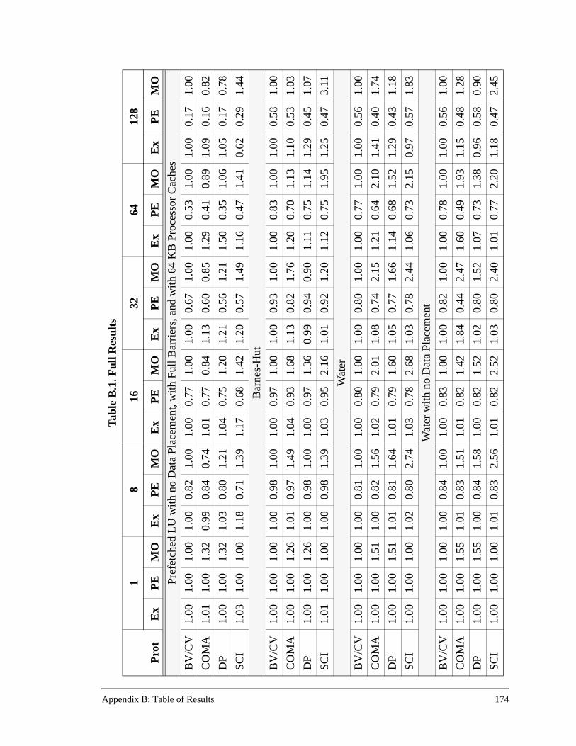
Appendix B: Table of Results 174
Tab
le B
.1. F
ull R
esul
ts
18
1632
6412
8
Pro
tE
xP
EM
OE
xP
EM
OE
xP
EM
OE
xP
EM
OE
xP
EM
OE
xP
EM
O
Pref
etch
ed L
U w
ith n
o D
ata
Plac
emen
t, w
ith F
ull B
arri
ers,
and
with
64
KB
Pro
cess
or C
ache
s
BV
/CV
1.00
1.00
1.00
1.00
0.82
1.00
1.00
0.77
1.00
1.00
0.67
1.00
1.00
0.53
1.00
1.00
0.17
1.00
CO
MA
1.01
1.00
1.32
0.99
0.84
0.74
1.01
0.77
0.84
1.13
0.60
0.85
1.29
0.41
0.89
1.09
0.16
0.82
DP
1.00
1.00
1.32
1.03
0.80
1.21
1.04
0.75
1.20
1.21
0.56
1.21
1.50
0.35
1.06
1.05
0.17
0.78
SCI
1.03
1.00
1.00
1.18
0.71
1.39
1.17
0.68
1.42
1.20
0.57
1.49
1.16
0.47
1.41
0.62
0.29
1.44
Bar
nes-
Hut
BV
/CV
1.00
1.00
1.00
1.00
0.98
1.00
1.00
0.97
1.00
1.00
0.93
1.00
1.00
0.83
1.00
1.00
0.58
1.00
CO
MA
1.00
1.00
1.26
1.01
0.97
1.49
1.04
0.93
1.68
1.13
0.82
1.76
1.20
0.70
1.13
1.10
0.53
1.03
DP
1.00
1.00
1.26
1.00
0.98
1.00
1.00
0.97
1.36
0.99
0.94
0.90
1.11
0.75
1.14
1.29
0.45
1.07
SCI
1.01
1.00
1.00
1.00
0.98
1.39
1.03
0.95
2.16
1.01
0.92
1.20
1.12
0.75
1.95
1.25
0.47
3.11
Wat
er
BV
/CV
1.00
1.00
1.00
1.00
0.81
1.00
1.00
0.80
1.00
1.00
0.80
1.00
1.00
0.77
1.00
1.00
0.56
1.00
CO
MA
1.00
1.00
1.51
1.00
0.82
1.56
1.02
0.79
2.01
1.08
0.74
2.15
1.21
0.64
2.10
1.41
0.40
1.74
DP
1.00
1.00
1.51
1.01
0.81
1.64
1.01
0.79
1.60
1.05
0.77
1.66
1.14
0.68
1.52
1.29
0.43
1.18
SCI
1.00
1.00
1.00
1.02
0.80
2.74
1.03
0.78
2.68
1.03
0.78
2.44
1.06
0.73
2.15
0.97
0.57
1.83
Wat
er w
ith n
o D
ata
Pla
cem
ent
BV
/CV
1.00
1.00
1.00
1.00
0.84
1.00
1.00
0.83
1.00
1.00
0.82
1.00
1.00
0.78
1.00
1.00
0.56
1.00
CO
MA
1.00
1.00
1.55
1.01
0.83
1.51
1.01
0.82
1.42
1.84
0.44
2.47
1.60
0.49
1.93
1.15
0.48
1.28
DP
1.00
1.00
1.55
1.00
0.84
1.58
1.00
0.82
1.52
1.02
0.80
1.52
1.07
0.73
1.38
0.96
0.58
0.90
SCI
1.00
1.00
1.00
1.01
0.83
2.56
1.01
0.82
2.52
1.03
0.80
2.40
1.01
0.77
2.20
1.18
0.47
2.45
References 175
References
[1] G. Abandah and E. Davidson. Effects of Architectural and Technological Advanceson the HP/Convex Exemplar’s Memory and Communication Performance. In Pro-ceedings of the 25th Annual International Symposium on Computer Architecture,pages 318-329. June 1998.
[2] A. Agarwal, R. Simoni, J. Hennessy, and M. Horowitz. An evaluation of directoryschemes for cache coherence. In Proceedings of the 15th Annual InternationalSymposium on Computer Architecture, pages 280-289, June 1988.
[3] J. K. Archibald. The Cache Coherence Problem in Shared-Memory Multiproces-sors. Ph.D. Dissertation, Department of Computer Science, University of Washing-ton, February 1987.
[4] G. Astfalk and K. Shaw. Four-State Cache-Coherence in the Convex Exemplar Sys-tem. Convex Computer Corporation, October 1995.
[5] BBN Laboratories, Butterfly Parallel Processor. Tech. Rep. 6148, Cambridge, MA,1986.
[6] T. Brewer. Personal Communication, February 1998.
[7] T. Brewer and G. Astfalk. The evolution of the HP/Convex Exemplar. In Proceed-ings of COMPCON Spring’97: Forty Second IEEE Computer Society InternationalConference, pages 81-86, February 1997.
[8] H. Burkhardt III, S. Frank, B. Knobe, and J. Rothnie. Overview of the KSR-1 Com-puter System. Tech. Rep KSR-TR-9202001, Kendall Square Research, Boston,February 1992.
[9] L. Censier and P. Feautrier. A New Solution to Coherence Problems in MulticacheSystems. IEEE Transactions on Computers, C-27(12):1112-1118, December 1978.
[10] D. Chaiken, J. Kubiatowicz, and A. Agarwal. LimitLESS Directories: A ScalableCache Coherence Scheme. In Proceedings of the Fourth International Conferenceon Architectural Support for Programming Languages and Operating Systems,pages 224-234, April 1991.
[11] R. Clark. Personal Communication, February 1998.
[12] A. Cox and R. Fowler. Adaptive Cache Coherency for Detecting Migratory SharedData. In Proceedings of the 20th Annual International Symposium on ComputerArchitecture, pages 98-108, May 1993.
[13] F. Dahlgren, M Dubois, and P. Stenstrom. Combined Performance Gains of SimpleCache Protocol Extensions. In Proceedings of the 21st International Symposium onComputer Architecture, pages 187-197, April 1994.
[14] Data General Corporation. Aviion AV 20000 Server Technical Overview. DataGeneral White Paper, 1997.
References 176
[15] B. Falsafi, A. Lebeck, S. K. Reinhardt, et al. Application-Specific Protocols forUser-Level Shared Memory. In Proceedings of Supercomputing ‘94, pages 380-389, November 1994.
[16] B. Falsafi and D. Wood. Reactive NUMA: A Design for Unifying S-COMA andCC-NUMA. In Proceedings of the 24th International Symposium on ComputerArchitecture, pages 229-240, May 1997.
[17] M. Galles. Spider: A High-Speed Network Interconnect. IEEE Micro, 17(1):34-39,January-February 1997.
[18] K. Gharachorloo. Memory Consistency Models for Shared-Memory Multiproces-sors. Ph.D. Dissertation, Stanford University, Stanford, CA, December 1995.
[19] H. Grahn and P. Stenstrom. Evaluation of a Competitive-Update Cache CoherenceProtocol with Migratory Data Detection. In Journal of Parallel and DistributedComputing, vol. 39, no. 2, pages 168-180, December 1996.
[20] A. Gupta, W.-D. Weber, and T. Mowry. Reducing Memory and Traffic Require-ments for Scalable Directory-Based Cache Coherence Schemes. In Proceedings ofthe 1990 International Conference on Parallel Processing, pages I.312-I.321,August 1990.
[21] E. Hagersten, A. Landin, and S. Haridi. DDM—A Cache-Only Memory Architec-ture. IEEE Computer, pages 44-54. September 1992.
[22] J. Heinlein. Optimized Multiprocessor Communication and Synchronization Usinga Programmable Protocol Engine. Ph.D. Dissertation, Stanford University, Stan-ford, CA, March 1998.
[23] M. Heinrich, J. Kuskin, D. Ofelt, et al. The Performance Impact of Flexibility in theStanford FLASH Multiprocessor. In Proceedings of the Sixth International Confer-ence on Architectural Support for Programming Languages and Operating Sys-tems, pages 274-285, October 1994.
[24] J. Hennessy and D. Patterson. Computer Architecture: A Quantitative Approach.Morgan Kaufmann Publishers, San Mateo, CA, 1990.
[25] C. Holt, M. Heinrich, J. P. Singh, et al. The Effects of Latency, Occupancy, andBandwidth in Distributed Shared Memory Multiprocessors. Technical Report CSL-TR-95-660, Computer Systems Laboratory, Stanford University, January 1995.
[26] C. Holt, J.P. Singh, and J. Hennessy. Application and Architectural Bottlenecks inLarge Scale Distributed Shared Memory Machines. In Proceedings of the 23rdInternational Symposium on Computer Architecture, pages 134-145, May 1996.
[27] T. Joe and J. L. Hennessy. Evaluating the Memory Overhead Required for COMAArchitectures. In Proceedings of the 21st International Symposium on ComputerArchitecture, pages 82-93, April 1994.
References 177
[28] J. Kuskin, D. Ofelt, M. Heinrich, et al. The Stanford FLASH Multiprocessor. InProceedings of the 21st International Symposium on Computer Architecture, pages302-313, April 1994.
[29] J. S. Kuskin. The FLASH Multiprocessor: Designing a Flexible and Scalable Sys-tem. Ph.D. Dissertation, Stanford University, Stanford, CA, November 1997.
[30] J. Laudon and D. Lenoski. The SGI Origin: A ccNUMA Highly Scalable Server. InProceedings of the 24th International Symposium on Computer Architecture, pages241-251, June 1997.
[31] D. Lenoski, J. Laudon, K. Gharachorloo, et al. The Stanford DASH Multiprocessor.IEEE Computer, 25(3):63-79, March 1992.
[32] T. D. Lovett and R. M. Clapp. STiNG: A CC-NUMA Computer System for theCommercial Marketplace. In Proceedings of the 23rd International Symposium onComputer Architecture, pages 308-317, May 1996.
[33] T. D. Lovett, R. M. Clapp, and R. J. Safranek. NUMA-Q: An SCI-based EnterpriseServer. Sequent Computer Systems Inc., 1996.
[34] M. Martonosi, D. Ofelt, and M. Heinrich. Integrating Performance Monitoring andCommunication in Parallel Computers. In ACM SIGMETRICS International Con-ference on Measurement and Modeling of Computer Systems, pages 138-147, May1996.
[35] T. C. Mowry. Tolerating Latency Through Software-Controlled Data Prefetching.Ph.D. Dissertation, Stanford University, Stanford, CA, June 1994.
[36] M. Papamarcos and J. Patel. A Low Overhead Coherence Solution for Multiproces-sors with Private Cache Memories. In Proceedings of the 11th International Sympo-sium on Computer Architecture, pages 348-354, 1984.
[37] PCI Special Interest Group. PCI Local Bus Specification, Revision 2.1. June, 1995.
[38] G.F. Pfister et al. The IBM Research Parallel Processor Prototype (RP3): Introduc-tion and Architecture. In Proceedings of the 1985 Conference on Parallel Process-ing, pages 764-771, 1985.
[39] S. Reinhardt, J. Larus, D. Wood. Tempest and Typhoon: User-Level Shared Mem-ory. In Proceedings of the 21st International Symposium on Computer Architecture,pages 325-336, April 1994.
[40] S. Reinhardt, R. Pfile, and D. Wood. Decoupled Hardware Support for DistributedShared Memory. In Proceedings of the 23rd International Symposium on ComputerArchitecture, pages 34-43, May 1996.
[41] M. Rosenblum, S. A. Herrod, E. Witchel, and A. Gupta. Complete Computer Simu-lation: The SimOS Approach. IEEE Parallel and Distributed Technology, 3(4):34-43, Winter 1995.
References 178
[42] M. Rosenblum, J. Chapin, D. Teodosiu, et al. Implementing Efficient Fault Con-tainment for Multiprocessors. Communications of the ACM, 39(3):52-61, Septem-ber 1996.
[43] E. Rothberg, J.P. Singh, and A. Gupta. Working Sets, Cache Sizes, and Node Gran-ularity Issues for Large-Scale Multiprocessors. In Proceedings of the 20th AnnualInternational Symposium on Computer Architecture, pages 14-25, May 1993.
[44] Scalable Coherent Interface, ANSI/IEEE Standard 1596-1992, August 1993.
[45] R. Simoni. Cache Coherence Directories for Scalable Multiprocessors. Ph.D. Dis-sertation, Stanford University, Stanford, CA, October 1992.
[46] J. P. Singh, T. Joe, A. Gupta, and J. L. Hennessy. An Empirical Comparison of theKendall Square Research KSR-1 and Stanford DASH Multiprocessors. In Proceed-ings of Supercomputing ‘93, pages 214-225, November 1993.
[47] J. P. Singh, W.-D. Weber, and A. Gupta. SPLASH: Stanford Parallel Applicationsfor Shared Memory. Computer Architecture News, 1992.
[48] M. D. Smith. Support for Speculative Execution in High-Performance Processors.Ph.D. Dissertation, Stanford University, Stanford, CA, November 1992.
[49] R. Stallman. Using and Porting GNU CC. Free Software Foundation, Cambridge,MA, January 1992.
[50] V. Soundararajan. Personal communication, May 1998.
[51] V. Soundararajan, M. Heinrich, B. Verghese, et al. Flexible Use of Memory forReplication/Migration in Cache-Coherent DSM Multiprocessors. In Proceedings ofthe 25th International Symposium on Computer Architecture, pages 342-355, July1998.
[52] P. Stenstrom, M. Brorsson, and L. Sandberg. An Adaptive Cache Coherence Proto-col for Migratory Sharing. In Proceedings of the 20th Annual International Sympo-sium on Computer Architecture, pages 109-118, May 1993.
[53] P. Stenstrom, T. Joe, and A. Gupta. Comparative Performance Evaluation of Cache-Coherent NUMA and COMA Architectures. In Proceedings of the 19th AnnualInternational Symposium on Computer Architecture, pages 80-91. May 1992.
[54] R.J. Swan et al. The implementation of the Cm* multi-microprocessor. In Proceed-ings AFIPS NCC, 645-654, 1977.
[55] C. K. Tang. Cache Design in the Tightly Coupled Multiprocessor System. In AFIPSConference Proceedings, National Computer Conference, pages 749-753, June1976.
[56] J. Torrellas. Multiprocessor Cache Memory Performance: Characterization andOptimization. Ph.D. Dissertation, Stanford University, Stanford, CA, August 1992.
References 179
[57] J. Torrellas, C. Xia, and R. Daigle. Optimizing Instruction Cache Performance forOperating System Intensive Workloads. In Proceedings of the First InternationalSymposium on High-Performance Computer Architecture, pages 360-369, January1995.
[58] J. Veenstra and R.J. Fowler. A Performance Evaluation of Optimal Hybrid CacheCoherence Protocols. In Proceedings of the Fifth International Conference onArchitectural Support for Programming Languages and Operating Systems, pages149-160, October 1992.
[59] W.-D. Weber. Personal Communication, February 1998.
[60] W.-D. Weber, S. Gold, P. Helland, et al. The Mercury Interconnect Architecture: ACost-Effective Infrastructure for High-Performance Servers. In Proceedings of the24th International Symposium on Computer Architecture, pages 98-107, June 1997.
[61] W.-D. Weber. Scalable Directories for Cache-Coherent Shared Memory Multipro-cessors. Ph.D. Dissertation, Stanford University, Stanford, CA, January 1993.
[62] S. C. Woo, M. Ohara, E. Torrie, et al. The SPLASH-2 Programs: Characterizationand Methodological Considerations. In Proceedings of the 22nd International Sym-posium on Computer Architecture, pages 24-36, June 1995.
[63] C. Xia and J. Torrellas. Instruction Prefetching of Systems Codes with Layout Opti-mized for Reduced Cache Misses. In Proceedings of 23rd International Symposiumon Computer Architecture, pages 271-282, May 1996.
[64] K. Yeager. The MIPS R10000 Superscalar Microprocessor. IEEE Micro, 16(2):28-40, April 1996.
[65] Z. Zhang and J. Torrellas. Reducing Remote Conflict Misses: NUMA with RemoteCache versus COMA. In Proceedings of the Third Annual Symposium on High Per-formance Computer Architecture. February 1997.