Embed Size (px)
Citation preview
,\/NASA Technical Memorandum 81264 USAAVRADCOM TR 81-A-6
The Phenomenonof Dynamic StallW. J. McCroskey
• (_lALiA-Tt_-dl,toq) 'P,],.; PHENOI4Et_ON O_ DY_A_J.C Ndl--)'Ju295'].'ALL {RASk) 3.) I._ IIC AO_/{4[' A01 CSCL O|A
OJ_clds
G3/O_ 41b£u
!=
i._ March 1981
_- _':' "2_s,_AcIL,,\i
_,:,, ..... ..,,.,_-:
1981011.501
https://ntrs.nasa.gov/search.jsp?R=19810011501 2018-06-03T10:08:06+00:00Z
NASA Technical Memorandum 131264 USAAVRADCOM TR _1A-6,:T
_--
The-Phenomenon of Dynamic--StallW. J. McCroskey, Aeromechanics Laboratory
AVRADCOM Research and Technology LaboratoriesAmes Research Center, Moffett Field, California
N/A A
kdAmes Rosei|rchCogfler
1981011501-TSA03
Lecture Notes On
THE PHENOMENON OF DYNAMIC STALL
by
W. J. HcCroskey
Ames Research Center, NASAand
O. S. Army Research and Technology Laboratories (AVP_DCOM)Ames Research Center
Moffett Field, California, USA
Presented to yon K_rm_n Institute Lecture Series on
Unsteady Airloads and Aeroelastic Problems in Separated
and Transonic Flows
:1Rhode-Salnt-Ct'n_-'se, Belgium
9-13 March 1981
1981011501-TSA04
THE PIJENOMENON OF DYNAMIC STALL
I W. J, McCroskey
i Ames Research Center, NASA and U. S. Army Research
_" and Technology Laboratories (AVRADCOM)
Ames Research Center, Moffett Field, California, USA
1. INTRODUCTION
Stall and its consequences are fundamentally important to the design and
operation of flight vehicles. A certain degree of unsteadiness always accom-
panies tbe flow over an airfoil or other streamlined body at high angle of
attack, but the stall o_ a lifting surface undergoing unsteady motion is even
more complex than static stall. Although much progress has been made in
recent years, dynamic stall remains a major unsolved problem with a variety of
current applications in aeronautics, hydrodynamics, and wind engineering.
These lectures will summarize the main physical features of the phenomenon
and the aLgempts that have been made to predict it. The information presented
is drawn mainly from recent review articles (Ref. I-5) and investigations by
the author and his colleagues (Refs. 6-9). Since a large fraction of the
existing knowledge has come from experimental research, the details of dynamic
stall are discussed principally in physical terms.
2. GENERAL FEATURES
Above a certa.Ln critical anglo of attack, the flow around a slender lift-
int. surface breaks down into the phenomenon ca!led stall. On an oscillating
airfoil whose incidence is increasing r_oidly, the onset of the stall can be
delayed to iucidenees considerably in excess of the static stall angle. Once
dynamic stall does occur, however, it is nsually more severe and more persis-
tent than static stall. The attendaet aerodynamic forces and moments exhibit
large amounts of hysteresis wit}] respect to the inst_qnt:meous angle of attack
,x(t), especially if _ oscillates around some menn v_lue Lxo that is of the
order of the static sial] angle ass.
1981011501-T£AOfi
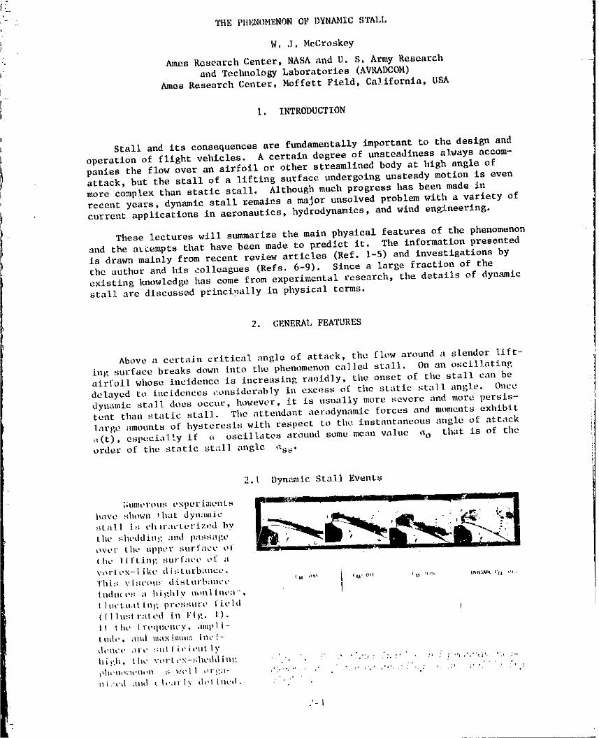
It b_gias near the leading edge and passe_ throu_l the distinct s_agesillustrated in Figs. 2 and 3. Figure 2 a_d the a_ompanying Table I show
2 tiletypiea] hysteresls in CL, CM, and CD versu_ angle of attack, wb£1oFig. 3 Indicates tile loci of the various stall events on the airfoil plotted
"i in an x-t diagram.
In the unseparated region betw=on points i and 2 in Figs. 2 and 3,
the llft and pitching moment follow approximately the trends of unsteady
linear thin airfoil theory. Sometime after n exceeds ass, a thin layer
of reversed flow develops at the bottom of the boundary Layer. On the
so-called trailing-edge stalling airfoils (e.g., Fig. 3), this tongn_ ofreversed flow starts at the rear of the airfoil and moves forward to the
? leadlng-edge region, whereas on leading-edge stalling profiles it develops
aa
25 .... STATIC 2 _ ]_
,,r
0 I I t_
6 3_12 5
"'---- UNSEPARATED 8
CM _ 15
4b EPARAT£O 22
=/; m_-- 125I 0 4," 5
n
co o tINS[- PAHAT [ I0 _'_J
!2 4 6 8 1.0
..... _2 .... • "10 20 LEAI)ING 1RAILING
,_.de_ EDG! EOGE
i',',,:.'.' Vii-, . 4;W'r:'! ,;t ,_<., = i!.::;,, .':'c_' :;:, :qr,'_' .,:o'.qt', '" ::,' ,,.'(.'-
" 1981011501-TSA06
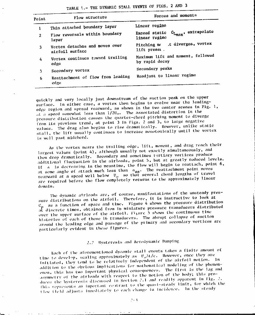
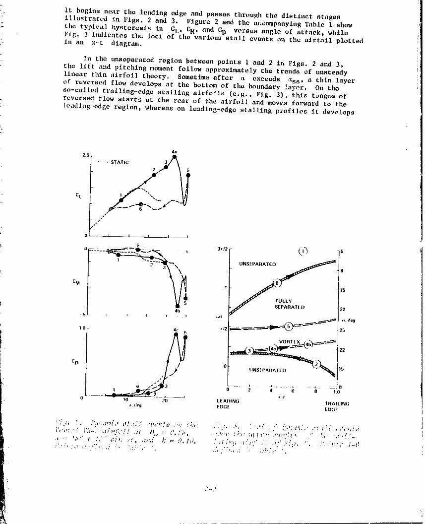
TABLE !.- THE DYNAMIC STAI.I,EVENTS OF FIGS. 2 AND 3
Point Flow structure Forces and moments
I Thin attached boundary layer Linear regime
2 Flow reversals within bouadary Exceed static CLmax, extrapolatelayer linear regime
3 Vortex detaches and moves over Pitching mr .t diverge$, vertex
airfoil surface llft preset.
4 Vortex continues toward trailing Maximum lift and moment, followed
edge by rapid decay
5 Secondary vortex Secondary peaks
6 Reattacl_ent of flow from leading Readjust to linear regime
edge
quickly and very locally just downstream of tilesuction peak o11 tileupper
surface, in either case, a vortex Lhen begins to evolve near tlle leading-edge region and spread rearward, as shown in the two center scenes in Fig. I,,,t a speed somewhat less than I/2U.... Tile associated distortion in the
pressure distribution causes the quarter-chord pitehlng moment tu diverge
from its previous trend, at point 3 in lqgs. 2 and 3, to large negative
values. 'Filedrag also begins to rise dramatically. However, unlike static
stall, tile lift asua] ]y coatinees to increase monotonically until the vortexis well i>ast mldeburd.
As tile w_rtex nears the trailing edge, lift, moment, and drag reach theirI;irgest values (point 4), although usually not exactly simultaneously, andthen drop dramatically. Secondary and sometimes tertiary vortices prodnceadditional flnetuatlon in tlleair loads, point 5, but at greatly reduced levels.
if a is decreasing in tilemeantime, tlm flow will begin to reatt;Ich, pelnt 6,
;it some angle of attack much less than _Xss. Tile reattaehment point movesrearward at a speed we[l below U,, so that sever_il chord lengths of travelilrc required before tile flow completely returns to tile approxlr_ltely lineardomain •
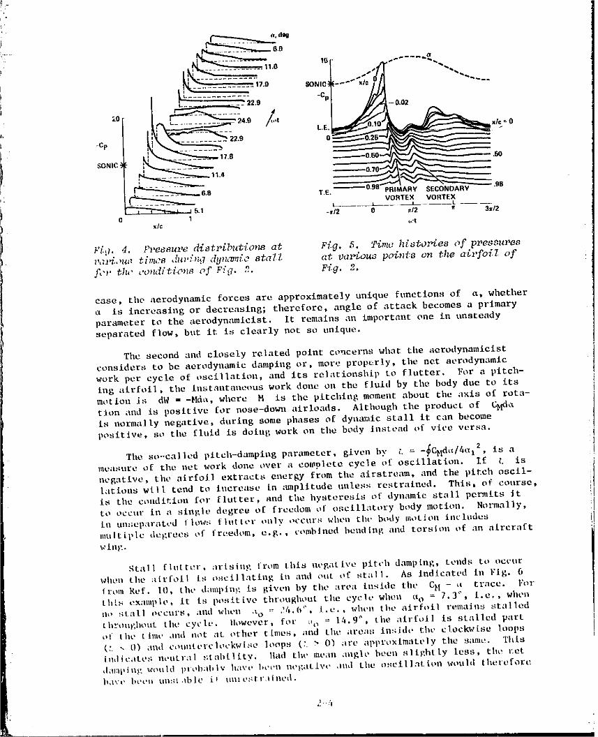
'rhe dynamic atrloads are, of course, manifestations of the unsteady pres-sure distributions on the airfoil. Therefore, it is instructive to look at
(; as a functlon of space and tlnie. Figure 4 shows the pressure dlstributionl_ discrete times, obtained from It*miniature pressure transducers distributed
over tlte upper surface of tile airfoil. Fil,urc 5 allOWS tile continuous timeh|storles of each of these 16 transducers. Tile abrupt collapse of suctionaround tile leading edge and passage of tile primary and secondary vortices arcparticularly evident ill these figures.
2.2 Ilysteresis and Aerodyulmlic Damping
Each of tile aforementioned dy;lamic still 1 events tilkes a fieitt" /ulleunt of
ttme to devt'l_,p, scaling approximately as U,,At/c. Ilowever+ once they are
hlltlated, t ht.y tend t,, be relatively tadel+eadeat of the ;IJrfo[1 motion. Ill
dtld it i oil [ tl t he obv toes imp l t cdt i oils for ma thereat I ca I mode 11 ill,, of t he phenom-tqlOll, this I1;Is two Important physical Collst+qtlellCt, s. Tile first Is tilt, I;|g and
•ISyl_ltlt'll'y tit" file :lirloads with respt,et to tilt" motion of the body; tills pro-
t]Ot, l,t; lilt, hysttut,sis d[+_cut;sed ill Sect[oo 2.1 dlld rcadIly apparent Ill l:tl:. 2.
Ihl:; rl'i_lt'._euts rill illlpeltdnt i't; itrast to tilt" qlla!_i-stt*ady Illlllt. for which the
I h,a' lit'Ill ;lOjllats Ii!t:m,,liately to £';It'h t'b. llll;t+ ill IIICidt'lh'e. lit the ste;hly
- + ..... _
I
i'981011501-TSA07
(leg
.9+........."++f ......"._'_..____...... 1'/.o SONIO_--- x/
L .......... = -c.
-Cp _,__ 22.9 O_
SONIC! _17.B _0,50 .50
11.4
6,8 T.E, PRIMARY SECONDARYVORTEX VORTEX
=5.1 .....-_12 0 ./2 f 3w/20 1x/c t.'t
_L:I. 4. Pz,esauz,edist_._bz,tio_ at Fig. 5. Time hL_to:.tes of prees_Pe_
l,,_J_:,,_+.._t_'mos ,f_l':%L,7 _(y_z_m_:ost_IZ at uczz'_ouapoit_t8 on the ate,foil of
fL.J'th+" _'o_2d/t£o_sof F:',7. 2. Fig. 2.
case, the aerodynamic forces are approximately unique functions of a, wheLher
a is increasing or decreasing; tllerefore, angle of attack becomes a primary
part,meter to the aerodynamlcist. It remains _In important one In unsteadyseparated flow, but it is clearly not so unique.
Tile second and closely related point ct,ncerns what tlteaerodynamlclst
considers to be aerodynamic damping or, more prop_rly, tile net aerodynamic
work per cycle of oscillation, and its relationsl_ip to flutter. For a pitch-
Ing alrfoil, tile ittstautaneous work done on the fluid by the body due to its
motion is dW = -Md_, wilerc M is the pitching moment about ti_e axis of rota-
tion and is positive for nose-dowll airloads. Altl_ough the product of C_<_is normally negative, during some phases of dynamic stall it can become
positive, so tile fluid is doing work on tllebody instead of vire versa.
The so-called pltch-dampit_g parameter, given bx' _ = -_CNd_t/4t_l2, is ameasure of tile net work done over a complete cycle of oscillation. If t, is
negative, tile airfoil extracts energy from tileairstream, and _he pitch oscil-
latioas will tend to increase [n _unplitudc unless restrained. This, of course,
is tile Collditiotl for litterer, and tileilysteresis of dynamic st;lll permits |tto occur in a single degree of freedom ef oscillatory body motion. Notmlally.
is un:;eparated I lew:; flutter only t_ceurs wllee tilt" body motion lsclt_desmt(1til, le degl'eos of frt_edom, e.g., combined belldinl,, itlld torsion of ;hi atrcr_lftwing.
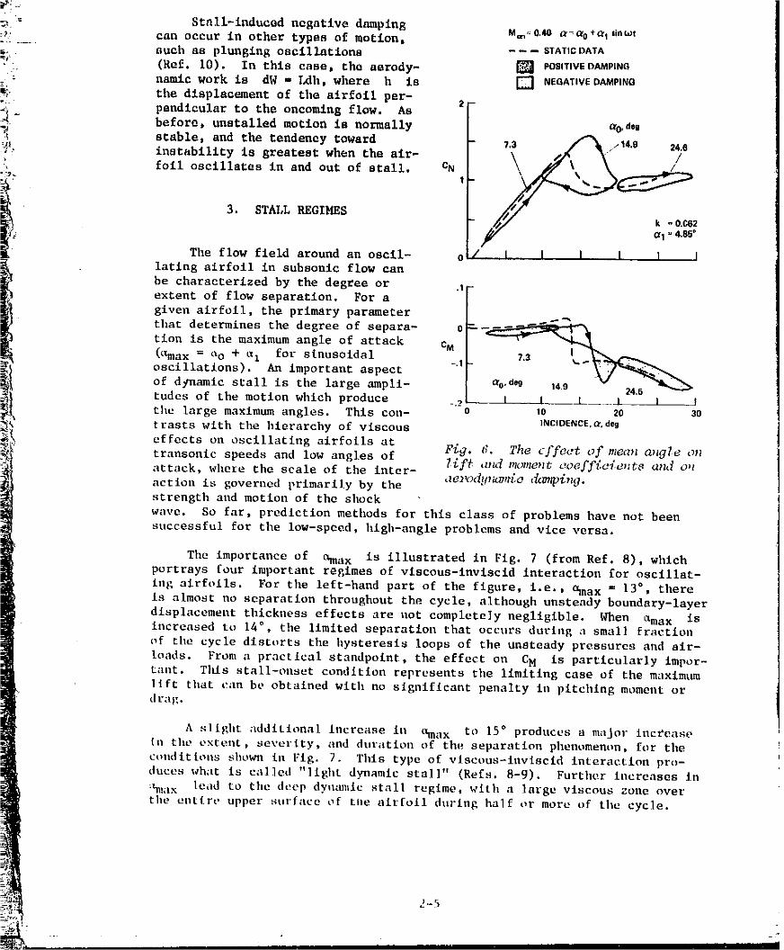
Stall fltltl'el', _lrfsinp" from El*is negative pitch damping, tends tt_ eccurwhen tile ;tirfoil Is oscillating ill and out ef st_lii. As Indicated ill Fig. 6
from R_,f. 10, tilt, dtlmplug is given by the :tree inside tile CH - _ trt*ce, l:ortilts example, it is positive throughout the cycle when a o = 7.3 °' i.e,, wilen
lie _Itall occurs. _nld when .to ,= 24.6". l.e.. whell the airfoil remains stalledtltrt_tl)lhout tile cycle. Ilowever, for _,_ = 14.9 ° , tile ;ill-foil is stalled partel the [ |ale ,Did not at *,tiler tlmes, laid the are;is in_iide tilt' clockt,,[se loops(:. "+ [)) illtd t't_tllltel'c|t+t'kwise ]I+OpS (:. > O) ;ire ;ll)prt);<lmate]y tile s+lmc+. 'this
isdic_ttes nt,atr;ll ,,;tabLilty. llad tilt' me,in ,ingle bees sllghtly less. tl_e l:et*l(ll:lpin+, would I)lob+ll.l%' Itilx't' I+et,n tle)_ative ,llld tile tlscillation would thereforeil_I_'( _ I+eell ilntl{ ,ibic i_ ulllt!,+:_l',liaed.
_.. :'t
' ' ' ' 9811 011501-TSA08
_5 = Stall-inducad negative dampingcan occur in other types of motion, M"o"0'4O _r'_°+cr_'i"_at
such as plunging oscillations - - - STATICDATA
!- (Ref. i0). In this case, tho aerody- [] POSITiV_OAMPINGnamic work is dW - Ldh, where h is [] NEGATtVEDAMPINa
_, the displacement of tlle airfoil per- 2"_ pendlcular to the oncoming flow. As
--_- before, unstalled motion is normally a_d,g
stable, and the tendency toward 7,3 _ / 14.g 24.6
JL instability is greatest when the air- \ .//l\\ _ J /• foll oscillates in and out of stall. CN \ f/ ",\\
"'J.
3. STALL REGIMES - 2
G1=4_85_
The flow field around an oscil- 0 i I l l l I l
i lating airfoil in subsonic flow can
be characterized by the degree or .I
extent of flow separation. For a
given airfoil, the primary parameter
that determines the degree of separa- c --_
tion is the maximum angle of attack CM(C_a x = t_o + tzI for slnosoidal
oscillations). An important aspect -"
of dynamic stall is the large ampli- 24.6
tudcs of the motion which produce -.2 I I _i_.... I l !
tile large maximum angles. This con- 10 20 3o
trasts with the hierarchy of viscous INCIDEmCE._r.deg
effects on oscillating airfoils at F_. t_. The cffoc.t of nzcc_ a,agTe o_transonic speeds and low angles of
attack, where the scale of the inter- llft _u_ moment c_oeff{c_ent8 _zn,__o_
action is governed primarily by the _ze1_)dll_u2_t_e,&m_p4n_3.
strength and motion of the shock
wave. So far, prediction methods for this class of problems have not been
successful for the low-speed, hlgh-angle problems and vice versa.
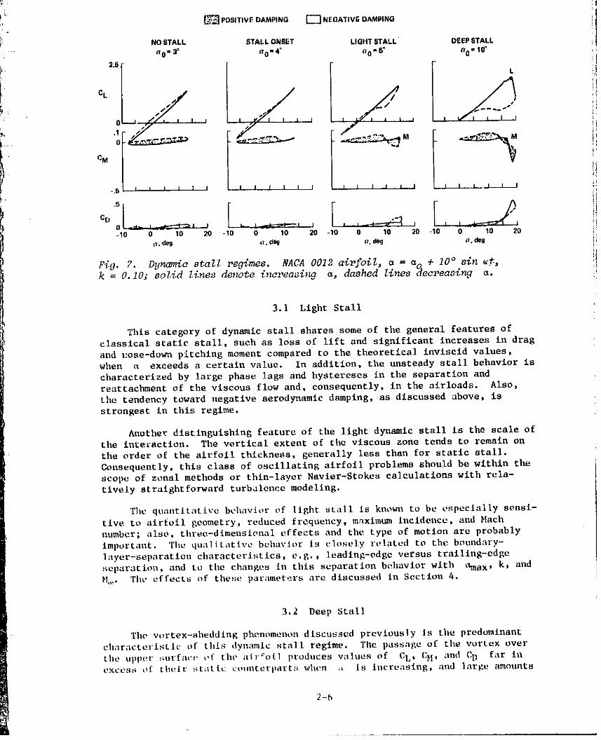
The importance of ¢hnax is illustrated in Fig. 7 (from Ref. 8), whichportrays four important regimes of vlscous-inviscld interaction for oscillat-
ing airfoils. For the left-hand part of the figure, i.e., Sma x ffi13 °, there
is almost no separation throughout the cycle, although unsteady boundary-layer
displacement thickness effects are uot completely negligible. When _max is
increased to 14 ° , the limited separation that occurs during n small fraction
of the cycle distorts tile hysteresis loops of the unsteady pressures and air-
loads. From a practical standpoint, the effect on CM is particularly Impor-
tant. TIds stall-onset condltlon represents tile limiting case of the maximum
lift that can be obtained with no s]gniflcane penalty in pitching moment or
drag.
A slight additional increase in _max to 15 ° produces a major increase
In the extent, severity, and duration of the separation phenomenon, for tile
coudltlons shown In Fig. 7. Tills type of vlscous-lnvlscld interaction pro-
duces what is called "light dynamic stall" (Refs. 8-g). Further increases In
_!ax le,ld to the deep dyamtllc stall regime, with a large viscous zoue over
t11e entire upper surface of t11e airfoil durlag half or more uf the cycle.
1981011501-TSA09
:I
POSITIVE DAMPING [,_ NEGATIV_ DAMPING l
tNO STALL STALL ONSET LIGHT STALL DEEP 6TALL
a 0- 3_ SO"4 ° a0,, 6° a 0 - 10" ,
i, L t
ct !Ii ! i
0 ,i i i i 1 I L//" J i I i I
J¢1
-.5 I I I I I I I I I i i i i _ i 1 I 1 I I F
ICD ' ' _ I i i i- q
-10 0 10 20 -10 0 10 20 -10 0 10 20 -10 0 10 20 _;]a, dog a. deg a. dog a. dog !
k = O.10; 8ol.id Zines denote i,ereasing a, dashed lznes _qeereas_n_, a.
3.1 Light Stall
This category of dynamic stall shares some of the general features of
classical static stall, such as loss of llft and stgnlfleant increases in drag
and i:ose-down pitching moment compared to the theoretical inviscld values,when _ exceeds a certain value. In addition, the unsteady stall behavior is
characterized by large phase lags and hystereses in the separation and
reattachment of the viscous flow and, consequently, in the alrloads. Also,
the tendency toward negative aerodynamic damping, as discussed above, is
strongest in this regime.
Another distinguishing feature of the light dynamic stall is the scale ofthe interaction. The vertical extent of the viscous zone tends to remain on
the order of the airfoil thickness, generally less than for static stall.
Consequently, this class of oscillatlng airfoil problems should be within the
scope of zonal methods or thin-layer Navler-Stokes calculations with rela-
tively straightforward turbalence modeling.
The quantltative behavior of light stall Is knoll to be especially sensl-
tlve to airfoil geometry, reduced frequency, maximum incidence, and Hath
number; also, three-dlmeusional effects and the type of motion are probablyimportant. The qualitative behavior is closely related to the boundary-
layer-separation characteristics, e,g.j leading-edge versus trailing-edge
separation, and to the changes in this separation behavior with tXmax, kt and_.. The effects of these parameters are discussed in Section 4.
3.2 Deep Stall
The vortex-shedding phenomenon discussed previously is the predominant
characteristic of this dynamic stall regime. The passage of the vortex over
the upper surfaev ef the airfoil produces values of EL, CH, and CD far inexcess ef their static counterparts when ,t is increasing, and large amounts
2-5
1981011501-TSA10
of hysteresis occur during the rest ofthe cycle. _he scale of the viscous NACA0012 M¢.=O_ .=_o+lO'|ln_.,!interaction zone is also large; the
thlcknoss of the viscous layer is on LIGHTRVAI.L
the vortex-shedding process.cM
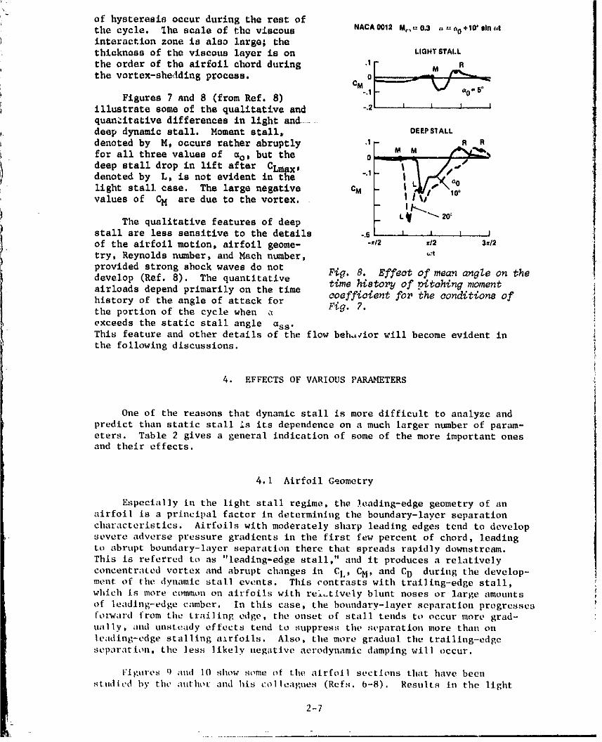
Figures 7 and 8 (from Ref. 8) 721 i _ a°'sillustrate some of the qualitative and . l l I
quan:'ita_ive differences in light and .....
deep dynamic stall. Moment stall, OEEPSlALL
denoted by M, occurs rather abruptly .1 R RM M _,
for all three values of _o, but the 0 "l _ A--'/deep stall drop in lift after CLmax _
denoted by L, is not evident in the " I ,/_N| L|/=_'_O
light stall case. The large negative CM I I"_/ 10"values of CH are due to the vortex.
The qualitative features of deep t_ -"'Z0°stall are less sensitive to the details -.s I I I Iof the airfoil motion, airfoil geome- -./2 s/2 3,/2
try, Reynolds number, and Math number, _t
provided strong shock waves do not FiG. 8. Effect of mean c_gle on the
develop (Ref. 8). The quantitative time histo_j of pitohlng momentalrloads depend primarily on the time
coeffloient for the conditions of
history of the angle of attack for Fig. 7.the portion of the cycle when
exceeds the static stall angle ass.This feature and other details of the flow beh,_ior will become evident in
the following discussions.
4. EFFECTS OF VARIOUS PARAb_TERS
One of the reasons that dynamic stall is more difficult to analyze and
predict than static stall is its dependence on a much larger number of param-
eters. Table 2 gives a general indication of some of the more important onesand their effects.
4. I Airfoil Geometry
Especially in the light stall regime, the leading-edge geometry of an
airfoil is a principal factor In determining the boundary-layer separation
characteristics. Airfoils with moderately sharp leading edges tend to develop
severe adverse pressure gradients in the first few percent of chord, leading
to abrupt boundary-layer separation there that spreads rapidly downstream.
This is referred to as "leadlng-edge stall," and it produces a relatively
concentrated vortex and abrupt changes In CL, CH, and CD during the develop-ment of the dynamic stall events. This contrasts with traillng-edge stall,
which is more common on airfoils with rei_tlvely blunt noses or large amounts
of leadlng-edge camber. In this case, the boundary-layer separation progresses
forward from the trailing edge, the onset of stall tends to occur more grad-ually, and unsteady effects tend to suppress the separation more than on
leading-edge stalling azrfoils. Also, the more gradual the trolling-edgeseparation, the less likely negative aerodynamic damping will occur.
Figures O amt lO show some of the airfoil sections that have been
studied by the author and his colleagues (Refs. b-8). Results in the light
2-7
1981011501-TSA11
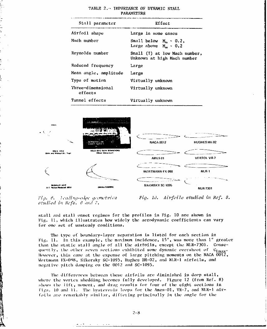
TABLE 2.'_ IbWORTANCE OF DYNAHIC STALLPARAMETERS
Stall parameter Ef feet
. Airfoil shape Largs in some cases
Hacb number Small below M_ ~ 0.2,
Large above M_ - 0,2
Reyno]ds number Small (?) at low Mach number,
Unknown at high Hath number
Reduced frequency Large
Hean angle, amplitude Largoi
Type of motion Virtually unknown
Three-dlmensional Virtually unknowneffects
Tunnel effects Virtually unknown
_Kt
•_ NACA0012 HUGHESHH02
AMES01 V[:RTOLVR7
_. '_'- ,. WORTMAN_ FX 098 NLR.S
_o,_*0 o_*_ SIKORSKY SC 1005aF_._,.,r*._,__'o o,¢.aa.c,,aamt NLH-7301
•Fid. o. [,',l,li_zg-,',t,w cj,',,mc_w,','_ Fig. 10. A[pfo{l_'. sfTed_;ed _;_, Ref. 8.stu,ti_<_d zb: ticft;, v" ,z_:d 7.
stall and stall enset regimes for tile profiles in Fig. i0 are sholca in
Fig. II, whlch illustrates how widely tile aerodynanlic coefficients can vary
for one set of unsteady eoudltions.
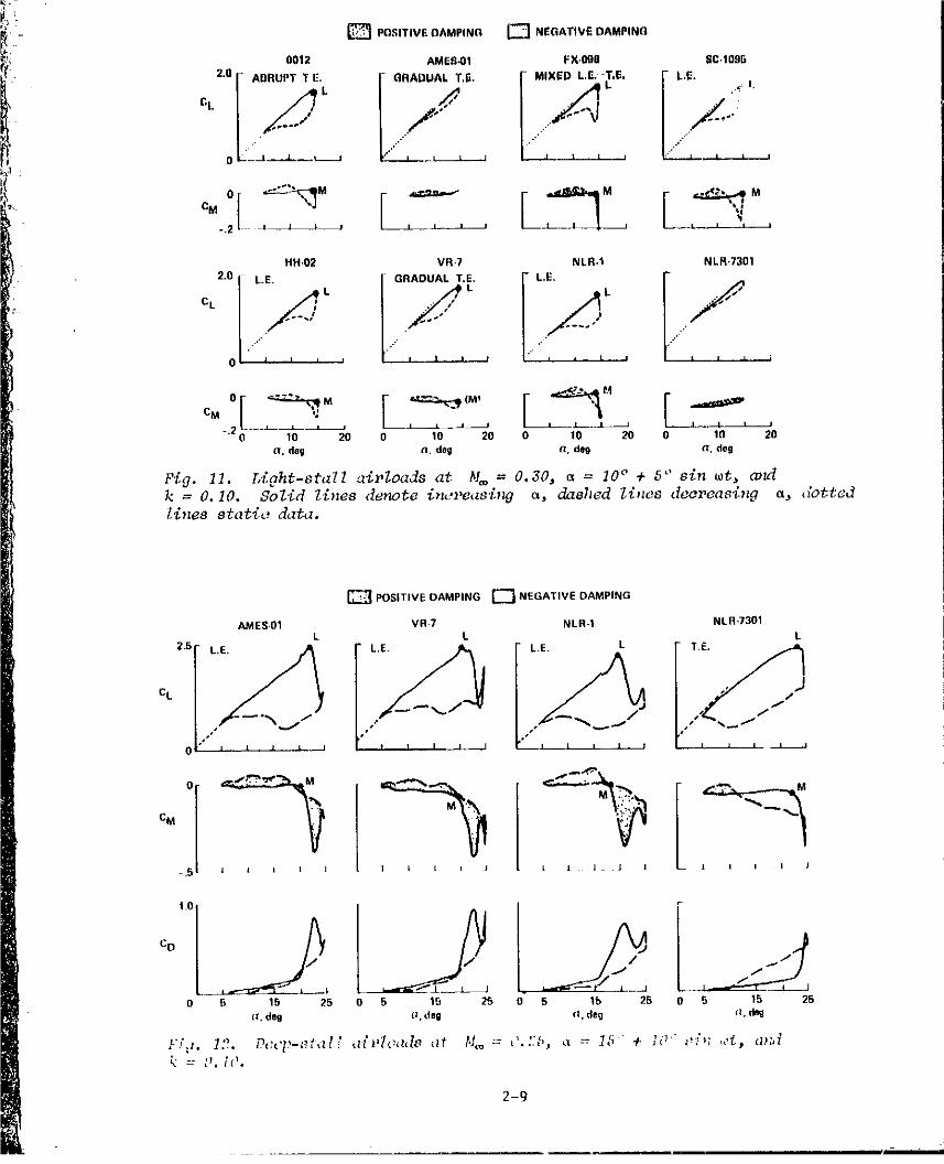
The type of boundary-layer separation Is listed for each section in
F[g. II. In this example, the maximum incidence, 15°, was more than 1° greater
than tilestatic stall angle of all the airfoils, except tilt!NI.R-7301. Conse-
que,:tly, tilt, other seven sections exhibited some dyllamic overshoot of Cl.ma x.IIowever, thl:; canle at the expense of large pitelltng 0loments on the NACA 0012,Wortnlaau FX-OqS, Sikorsky SC-1095, llughes tlH-02, and N1,R-1 airfoils, andnegative pitch damping on the 0012 alld SC-1095.
The differences between these airfoils are dinllnl.shed in deep stall,
where the vertex sheddlllg becomes fully developed. Figure 12 (from Ref. 8)MloWS tilt' lift, Ilhmlellt, Rlld drag results for four of tile eight sections inI'[_:s, 10 ;ind I1. The hysteresis loops for tile Ames-01, VR-7, and NI,R-I air-
otis are remarkably _hllilar, d iffvthlg prtuci.ally iu thv angle for tile
2-8
, , i • I
1981011501-TSA12
'- _ POSITIVE OAMPINC_ _] NENATIVE DAMPINQi.
_! 0012 AMES,01 FX.090SC.1095
• • 2.0 I- ABRUPT T E. (- GRADUAL TJ;. r MIXED L.E, +T,E, F L.E.._ L
,l/ / , '• " ' "f',l ":"0 V--I___L.___.j ..... |i:"" , i , ,
L
1 °,°I_'_" [_ [HH.02 VR-7 NLR.I NLR.7301
l-ou,+i0 "'" t n I I a " "', • n , I n I
.,o_o,_" F"+'++,+__ I _o__ J L_ __ , I / t I
20 0 10 20 0 10 20 0 1 20a, deg n. de@ _q.(Jell a. deg
Fig. 11. I,ight-staZ7 aiz,loads at M_ = 0.30, _ = 10° + 5" sin tot,op_k = O.I0. SoZid 7,inesdenote in,'reas'D_ _, da#hed I,inos deoreasing _, dotted/,inesstatio data.
POSITIVE DAMPING [_ NEGATIVE DAMPING
AMES 01 VR7 NLR-I NLR-7301L L L
CL _2"5 L'E''*"", z , _ , '""/L'_L'E'I1 l l I __""/ _ L T.E_
++S i i I I l I I ( I l l I J J J I I [ J
0 g 15 25 0 ,5 15 25 0 5 lb 25 0 5 15 25(I.deg (ideE (I,deg (I.dng
1-';::. 12. Pccp-_f.z./," _z[*'loadc_ _lt t'l_o= J.::[;, ct = 15 + }0"" _,',; ,,'t, ¢_n,t'_= U. IC.
2-9
Pl
1981011501-TSA13
onset of stall, in tho m_gnltnd¢ of the peak for_a_ and moments, and in the
strength of the secondary vortex at or n_ar %lax' Thc same could ba saidfor the other four alrfoilo (not shown).
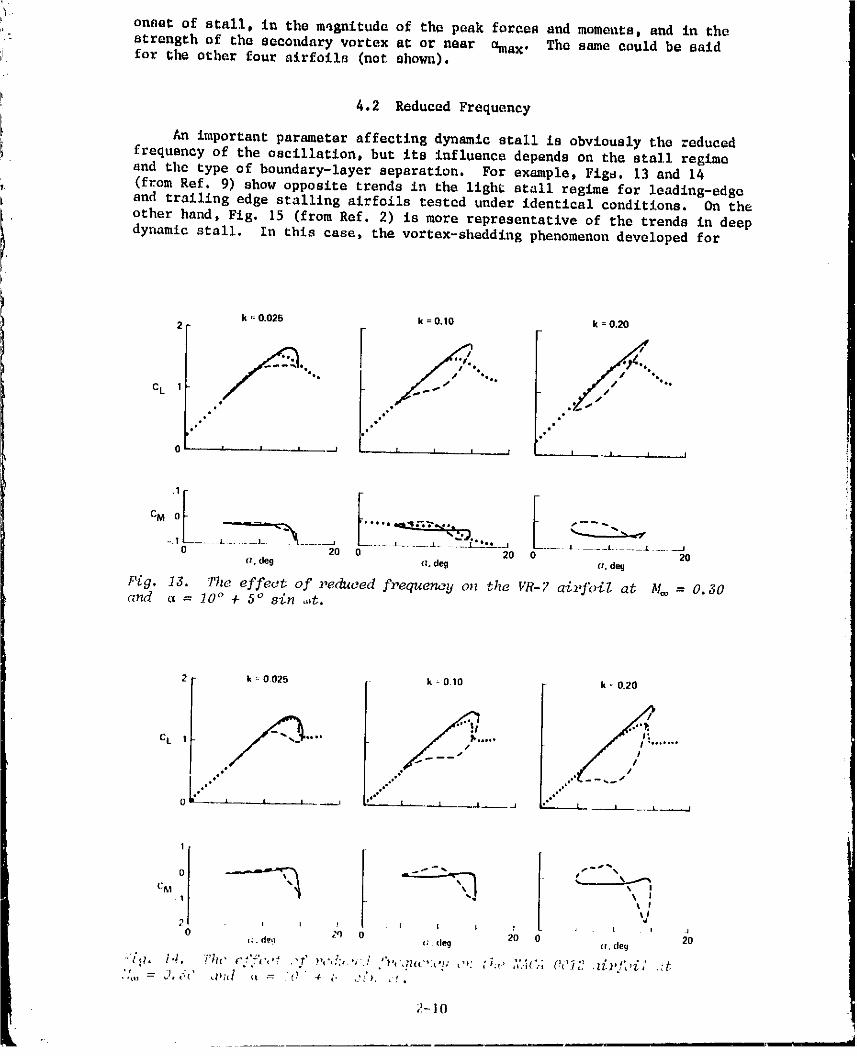
4.2 Reduced Frequency
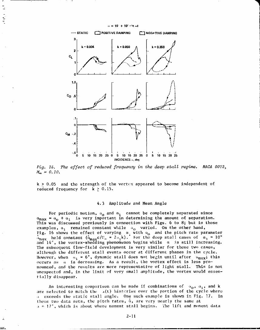
An important parameter affecting dynamic stall is obviously the reducedfrequency of the oscillation, but its influence depends on the stall regimeand _hc type of boundary-layer separation. For example, Figs. 13 and 14(from Ref. 9) show opposit_ trends in the light stall regime for leading-edg_and trailing edge stalling airfoils testod under identical conditions. On theother hand, Fig. 15 (from Ref. 2) is more representative of the trends in deepdynamic stall. In this case, the vertex-shQddlng phenomenon developed for
k = 0.025 k =0.10 k = 0.202
/s.°o • / %°°°'%*Q _ jJ *'*" ,#
C k• .* .sI
t" •° p alo
0 I I I ,,.M __ I I I I .-..,.,.-.A-.--.-- _ I I I
L ECM 0
0 20 20 0 20(_. deg oz.deg (.'. deq
Pig, 13. The effect of reduced frequency on tlzeVR-7 airfoil at M_ = 0.30c_>Idct= 10° + 5° si_ ,._t.
2 k _ 002,5 k " 0 10 k = 0.20
C L 1 "'" "'*" _°" "
..J° .+
._ oe. e o*"
1
C&I \ II I
VI J I I 1 t I I _00 2q 0 2{) 0
_:. de!l _:. dt_9 (I,day
:"/g. i.!, T'I." c'_'f',','f ,'f n,'_,s:,', .! "_,,',n(c,:,,_; ,,,: :;i,, ,','..;:., (!_"_2 .z_:_,]',,i," .:f
2-10
. _ I in -- i ill ili i -- q
i98'10i iS0i-TSAi4
.... STATIC [_ POBITIVEDAMPING _ NEG/-_TIVEDAMPING
3
/2 ,
1 -
/ /_ , _ J : : f" , , I I ; r ! ! i I I
1.0 /_;
cD .. ;;]]
,t _.f =
.1
CM -.2 "_
ti
-.4 _,
I = . . ; ; J • i , 3
"'60 5 10 15 20 25 5 1Q 15 20 25 5 10 15 20 25INCIDENCE.. de9
Fig. ]5. The effect of reduced frequency in the deep staZl regime. NACA 0022,
,V,:= 0.10.
k > 0.05 and the strength of the vortt.x appeared to become independent of
reduced frequency for k > O.15.
4.3 Amplitude and Moan Angle
For periodic motion, so and a z cannot be completely separated since
areax = uo + a I is very important in determining the amount of separation.
This was discussed previously in connection with Figs. 6 to 8; but in those
examples, _I remained constant while _o varied. On the other hand,
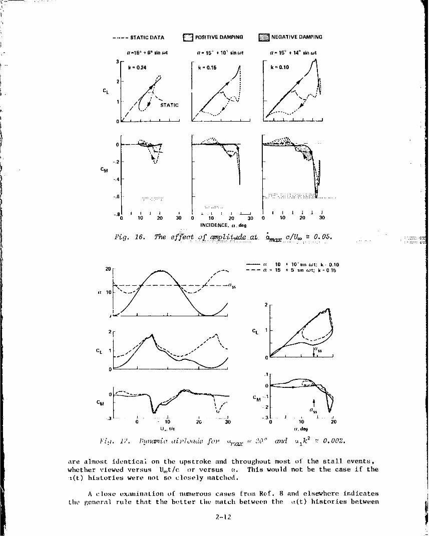
.Fig. 16 shows the effect of varying a with ao and the pitch rate parameter
'_aax held constant (_;maxC/U._ = 2tlk). For the deep sta]l cases of a I = 10 °and 14 °, the vortex-shedding phenomenon begins while a _s still increasing.
The subsequent flow-fleld development is very similar for these two cases,
although the different stall events occur at different phases in the cycle.
However, when _tI = 6 ° , dynamic stall does not begin until after _hnax; thisoccurs as _ is decreasing. As a result, the vortex effect is less pro-
nounced, and the results are more representative of light stall. This is not
unexpected and, in the limit of very sma]] amplitude, the vortex would essen-
Ilally disappear.
An interesting comparison can be made if combinations of (_o, ¢i), and karc selected to match the a(t) hist,:rles over the portion of the cycle where
,t exceeds the static stall angle. One such example is shown in Fig. !7. In
these two data sets, the pitch rates, _, are very nearly the same at
= 17 _',which is about where moment stall begins. The lift and moment data
2-11
1981011501 -TSBO1
i
POSITIVE DAMPING _ NEGATIVE DAMPINGSTATIC DATAn
a-15 _ *6" sinai ,- 1G:" • 10 _ sinai a- 15_ + 14° linwt
_ k _ 0"10
k = 0.24 k = 0.15
I" t
C L _/ '
1 // : \_ TATIC Q'; "_....>"*
0 _ g I i i I J , i I I 1 [ I I I
:..: .:=-: ,.
-.8 I I I 1 I ;- t l t _ I I 1 l J 110 20 30 0 10 20 30 10 20 30
INCIDENCE. a. deg
Fiq Is. The efJ_Ot.q2.a_._:L._& at _ c/U. _ O.OS............. :........ -r'no_:... . = .. . . :: .... :._;7 i-_
-- fz 10 _ 10's.* _t: k 0.10
CL 12[
CL 1 -" _. •
.1
CM CM -12
(xl_ V.3 _ 1 t _ J -3 J ' J J
0 10 2O 30 10 20
U,. tic .. de9
17. P,!_Z(:_'[a " "-- :,_0_' and uzk 2 _ 0.002.F,,'g.
are almost identical on the upstroke and throughout most of the stall events,whether viewed versus U=t/e or versus ¢¢. This would not be the case if the
t(t) histories were not so closely matched,
A close ex_m_ination of ntmlerous cases from Ref. 8 and elsewhere indicates
the _/eneral rule that tile better the matd_ between the _t(t) histories between
2-12
1981011501-TSB02
::: 7
astatle stall, amax, and areattachment , the better the match between the aero-i dynamic coefficients, at least for pitching motions _n deep stall. 1{owever,-- the extent to which title conclusion can be extended to light stall or to other
types of motion reum_ina to be established.
i 4.4 Mach Number
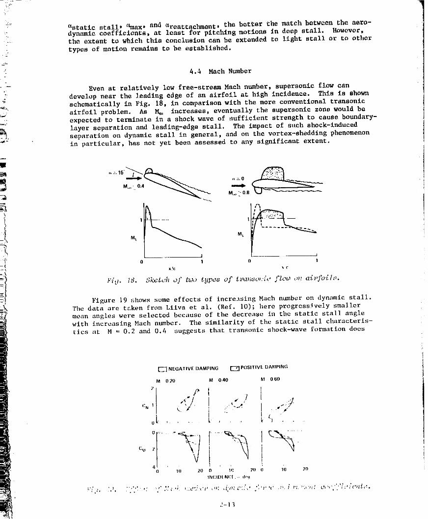
Even at relatively low free-stream Mash number, supersonic flow can
develop near the leading edge of an airfoil at high incidence. This is shown
_ schematically in Fig. 18, in comparison with the more conventional transonic3 airfoil problem. As M_ increases, eventually the supersonic mona would be• expected to tez_inate in a shock wave of _uffielent strength to cause boundary-
layer separation and leading-edge stall. The impact of s_teh shock-inducedseparation on dynamic stall in general, and on the vortex-sheddlng phenomenonin particular, has not yet been assessed to any significant extent.
- Mi M_
J --__ I
xlc • c
:: Figure 19 shows some effects of incre.tsing Mach number on dynamic stal].
The data are taken from Liiva et al. (Ref. I0); here progressively smallerinean angles were selected because of the decrease in the static stall angle
with increasing blach number. The similarity of the static stall characteris-
tics at M = 0.2 and 0.4 suggests that transonic shock-wave formation does
[_ NEGATIVE DAMPING _] POSITIVE DAMPING
M 020 M (].40 M (]60
/'I4"/. "
oL ....
0 111 2(] 1_ 711 1"0 _O
IN(:II)I N(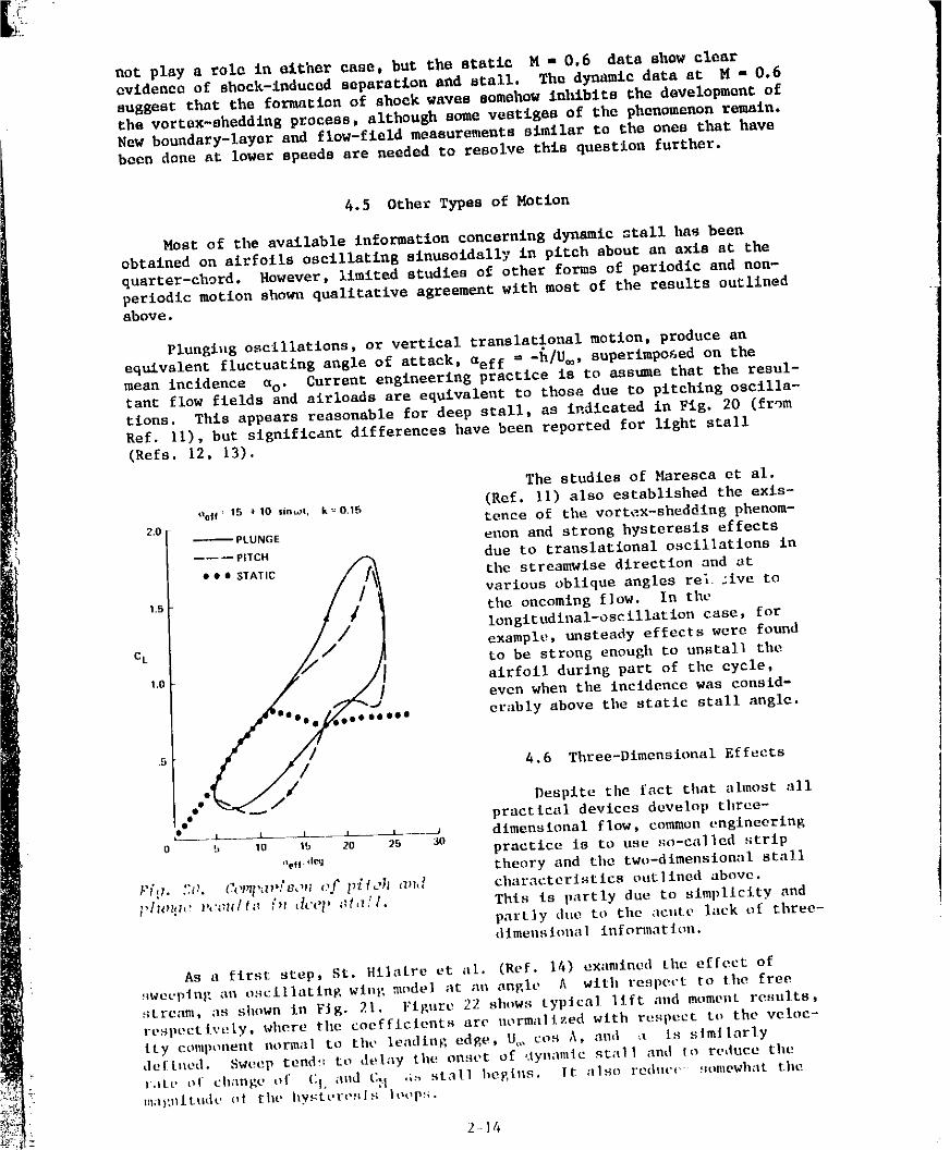
not play a role in either case, but the static M - 0.6 data show clearovidcnca of shock-induced separation and stall. The dynamic data at M - 0.6suggest that the formation of shock waves somehow in.bits the development ofthe vortax-aheddin 8 process, although some vestiges of the phenomenon remain.New boundary-layer and flow-field measurements similar to the ones that havebeen done at lower speeds are needed to resolve this question further.
4.5 Other Types of Motion
Most of the available information concerning dynamic stall has beenobtained on airfoils oscillating sinusoidally in pitch about an axis at thequarter-chord. However, limited studies o£ other forms of periodic and non-
periodic motion shown qualitative agreement with moat of the results outllnedabove.
Plunglug oscillations, or vertical translational motion, produce an
equivalent fluctuating angle of attack, aeff = -h/U_, superimposed on themean incidence as" Current engineering practice is to ass_e that the resul-tant flow fields and airloads arc equivalent to those due to pitching oscilla-
tions. Thla appears reasonable for deep stall, as indicated in Fig. 20 (from
Ref. ll), but significant differences have been reported for light stall(Refs. 12, 13),
The studles of Hareaea etal.
Oolf=15 +10 $inwL k_0.15 (Ref. ll) also established the exis-z0 tense of the vortex-sheddlng phenom-
_PLUNG£ anon and strong hysteresis effects
------PITCH _ due to translational oscillations in
• • e STATm // [_ the streamwlse direction and at
//various oblique angles tel :iv• to
15 the oncoming flow. In the
longltudinal-oscillatlon case, for
eL example, unsteady effects were found
i _ to be strong enough to unstal] tileto _ airfoil during part of the cycle,
even when the incidence was eonsid-
'_eeeeee• erably above tilestatic stall angle.4.6 Three-Dimensional Effects
ee_j//- Despite the fact that shnost allpractical devices develop three-
_-_ _ _---_ dimensional flow, common engineering
_. m _ 2o _ _0 practice is to use so-called strip
%, d_ theory and the two-dimenslonal sial]
F[_. ::_. _v_,d_&m (,f l>{lo]l a_hl characteristics outlined above._']m_ _:_ults i,_ _'_'p _t,7/l. This is partly due to slmpllclty and
partly due to the acute lack of three-dimensional information.
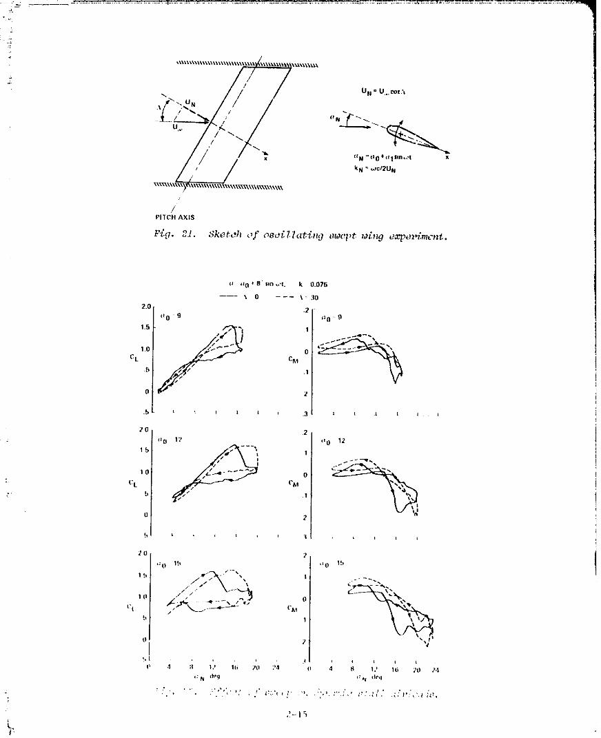
As a first step, St. Hilaire et al. (Ref. 14) examined tileeffect of_wet'plnR au oscillating wing model at an angle h with respect to the free
stream, as shown in Flg. 21. Figure 22 shows typical llft and moment results,
respectively, where the coefficients are normalized with respect to the veloc-
ity cemponent eurmal to the leading edge. U_,, cue A, and _t is similarlydef[ued. Sweep tend!: to delay the oest_t Of ,.iyoamicst;t|| and to reduce the
t,tte of change of CI. a0d (_I .i_ stall heglns. It ;l|so redttvc *iomewhat tilel!l;ll:ll_[tldt' of the hy_tt, r¢,_Us loop!;.
2-14
1.qR1nl 1Knl _Tq _nA
0 _z(]_ 8' sm ,.'t. k 0.07_
2.0 "i _l0 9_0 g
. _-_" oCL CI_I
2
°I2 I (_0 1220
(z0 12 1
0
0 CM
: CL 1
;
2
?
20 I 'ZO '__"
,,., /._?'% , ,./ ." "_.-_.-_ _._._
t!| / |!,
7
_, t ' ' ?4 4 tl 1_* 1(_ 20 ?4
_, 1981011501-TSE
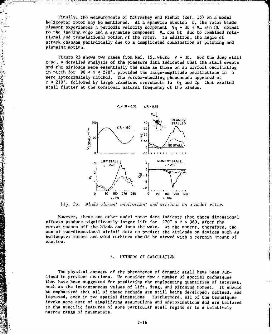
Finally, the measurements of McCroskey and Fiahur (Ref. 15) on a model
_. hullcopter rotor may be montloned. At a apanwlse atntlun r, the rotor blade
_ ..... element experiences a periodic velocity component VN - Or + V_ sin Rt normal
_; to the leading edge and a apnnwia_ component V_ cos fit due to combined rota-tional and translational motion of the rotor. In addition, the angle of
_ attack changes periodically due to a complicated combination of pitching and
plunging motion.
Figure 23 shows two cases from Ref. 15, where T = _t. For the deep stallcase, a dutailod analysis of the pressure data indicated that the stall events
and the airloads were essentially the same as those on an airfoil oscillating
e_. in pitch for 90 < T < 270 °, provided the large-amplitude oscillations in a
were approximately matched. The vortex-shedding phenomenon appeared at¥ ; 210 °, followed by large transient overshoots in CL and CM that excitedstall flutter at the torsional natural frequency of the blades.
However, these and other model rotor data indicate that three-dimensional
effects produce significantly larger llft for 270 = < T < 360, after the
vortex passes off the blade and into the wake. At the moment, therefore, the
use of two-dimensional airfoil data to predlct the alrloads on devices such ashelicopter rotors and wind turbines should be viewed with a certain _nount ofcaution.
5. _THODS OF CALCULATION
The physical aspects of the phenomenon of dynamic stall have been out-
lined in previous sections. We consider now a number of special techniques
that have been suggested for predicting the engineering quantities of interest,
such as the instantaneous values of lift, drag, and pitching moment. It should
be emphasized that all of these methods are still being developed, refined, and
improved, even in two spatial dimensions. Furthermore, all of the techniques
invoke some sort of simplifying assumptlons and approximations and are tailored
re the specific features of some particular stall regime or to a relativelynarrow range of parameters.
2-16
1981011501-TSB06
-N
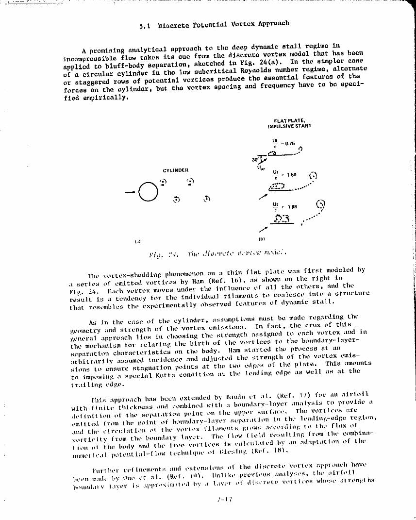
5.1 Dlacrcta Po_ontlal Vertex Approach 1
A promising analytical approach to tile deep dynamic stall regime inIncomproas_blo flow takes its cue from the discret_ vertex model that has been
applied to bluff-body separation, sketched £n Fig. 24(a). In the simpler case
of a circular cylinder in the low subcritical Re, acids number rQgium, alternate
or staggered rows of potential vertices produce the essential features ef _heforces on the cylinder, but the vortex spacing and frequency have to be speci-fied empirically.
FLATPLATE.IMPULSIVESTART
Ut . 0.76
CYLINDER U_
,,1.E0
ut =- 1.88 (_T
i=
/,_,H {hi
P/t;. ?4. i'h¢' ,!/_:,'pc/c V,'t,l,'.r rt,_tc.'.
The vortex-shedding phenomenon on a thin flat plate was first modeled bya series of emitted vortices by Ham (Ref. 1_), ;IS sholnl on tile right in
Fig. 24. Each vortex moves tinder the tnflllenee of all tile others, and theresult is a teodeney for tile individual filaments to coalesce into a structurethat resembles the experimental]y observed features of dynamic stall.
As Ill tllecase of tlle cylinder, a.-;sumptLon_must be made regarding the
geometry and strength of tile vortex emissions. In fact, tile crnx of this
gellera] appro:lcb ]tt, s ill choosing the strength assigned to each vortex ;lnd lotilemechanism for relarin£ the birth of tilevort tees to tllcboundary-layer-separation characteristics ell the body. Item started tile process st allarbitrarily asstmled incidence and adjusted tile strength of tile vortex emis-sions to unsure stagllatJOll pOlllt_ at tile two edges of th0 plate, This zlmoulltS
to impoaini: a special Kntta condition a'_ tile leading edIle as well as at tiletralllng edge.
rhl:; approach has been extendt,d by l_audu vt el. (Ref. 17) for an alrfollwith fJuitt, thi¢kt_ess and combined with a boundary--layer analysl_ to provide a
definition of the Bepal'atioll poillt on the upper tinl'[ilee. Tilt! vortices arecmttted |l-COl tile point of honndzlry-laycr separatioll Ill tilt' |estling-edl;e rate,till _
Slid tilt' c|rel:latiOll of tilt' vol'tt,x fll.lmt, nts glOW:; at'col'dlll_ _, tO the flux of
vorticlLy from the boundary layer. Tilt, flow iiehI reso1tlll), from tilt" eombina-I ion of the body led tilt, free vort ices [8 calculated I,3' :Ill adaptation of tilt'
ulullerlcdl pote.ntial-flow technitlUe at Glet;illg (gef. |8_.
Furl bet t'('flllelnt'nt,_i asd extenslolls of tile discrete vortex a|,ploach have
bt, t,n inildt, by One ct el. (Ref. Iq_. I]ulike prevh,us analy:;t!s, tile tiLl:foilbt,_llld,tlv I,ivt'r Is al, pr.'xlm:llt'd bv ;i 1,lvt, r t,t- dlscrt, te eel-Liter; who:_e Stl'ellt, th_;
2-1;
1981011501-TgR07
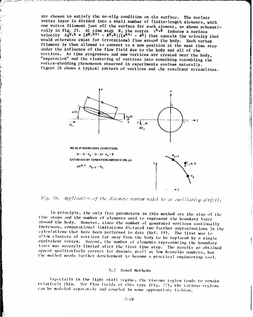
are chosen ,'o satisfy the no-slip condition on tl',a surface. Tha snrfacevortex layer is divided into a small n_bar of finite-length alements, witho110 vorte_ filament Just off the surface for e_ch element, as sho_nl schemati-
cally in Fig. 25. At time step N, the vorte_, v_, k Induces a surfaco
velocity AqN, k = [_N,k+1 _ _N,k]/[ak+1 _ sk] that cancels the velocity thatwould otlmrwlso exist for irrotatlonal flow around the body. Each vortex
filament ls then allow_d to convect to a new position at the next time step
under th= influence of the flow field due to the body and all of the
vortlees. As time progresses and new vortices are created near the body,
"separation" and the clustering of vortices into something resembling thevortex-sheddln_ _henomenon observed in experiments evolves naturally.
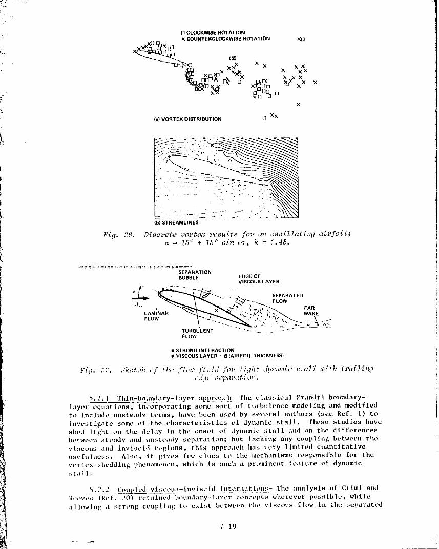
_ Figure 26 shows a typical pattern of vortices and the resultant streamlines.
h¥ _l
U,.. aU,..
NO SLIP BOUNDARY CONDITION:
(u- i) ' ny - (v - _') " n,_ =_0 @k �SATISFIED BY CONDITION IMPOSED ON A,b ,1 _ N k
In principle, tileonly free par_mleters in th£s method are the size of the
time steps and the mmlber of elements used to represent the boundary layer
around the body. _iowex,er, since the n_m_ber of generated voteless continually
Increa.qes, computational limitations dictated two further approxLmations in thecalculations that have been performed to date (Ref. lq). The first was to
;11 low clusters of vortices far away from the body to be replaced by a singleequivalent vortex. Second, the number at" elements representing the boundarylayer was severely limited after the first time step. The resells so obtainedappear qua|ltatix'ely correct for dynamic stall at low Reynolds ntunbers, butLilt' method needs further development to become a practical (?ngineerhlg tool.
5.2 Zonal Hethods
I':spcctally in the light ._tall regime, the viscous region teuds to remain
relatlx'ely thin. 15_I" flow fields of this type (Fig. .'7), the \'artou:4 reg[ens
(_lll lie modelel] sepa1a|elv ;Ind coupled ill sollle _lpproprltltc [il!:]l]OI1.
J-[8
= 1981011501-TSB08
[1CLOCKWIS_ ROTATIONX COUNTERCLOCKWISE ROTATION X[]
xX_nl E_X, Jl
x .x
?X
(a) VORTEX DISTRIBUTION [3 XX
!. ::.
J --:;. - ......
_1STREAMLINES
*) • • •Yi._, .6. DT.sevete cortege vcsul.ts Jbl, m2 oso_d.l.at_ntlairfoil;
= 15 _ + 15 ° sin wE, k = 2,45,
:_._::;_::__]::i:_TE.__ b:_;:__?_L: i::;-:;Z_;i-_i:E:_h'_.......SEPARATIONBUBBLE EDGE OF
VISCOUS LAYER
"f _,. B PARA.O"" , _,,_ _l_ d"P"P_ )>o-,J_£ FAR
TURBULENT ---_ ....... --_FLOW
• STRONG INTERACTION• VISCOUS LAYER _ OIAIBFOIL "IHICKNESS)
.. ...... 9h t • ., lt::_ll't,:. ... ::kctwn ,>f tt:c flow " '" .top /_ ,V,_,_zz,' _:f,z77 w[/h /;l_:d.l.li'l,ji h ,_[ll" il_.?t?tlll, It i' el;,
5.2.1 Thin-boundarl/-layt.r appro;ich- The classical Prandtl boundary-
layer equations, incorporating some sort of turbulence modeling and modified
to inchtde unsteady terms, llilve been used by several atitllors (see Ref. l) to
Investigate some of the characteristics of dynamic stall. These studies ilave
siled light on the delay in the onset of dyllami¢ still I lind on the differences
betwoell :itt, ady _lnd uosteady separaLien; but l:leking ally coupling between tileviscous and invisvid rt.gtons, tilts approach has very limited quantitat:lve
usefuhiess. Also, it gives few cities to Lilu mecilanisms responsible fer t.he
vorLex-sheddJlig pilellomt, iloilt wilit!il is i_ticil LI prominent feilttlre of dynamicst:al i.
5.'.__ t:o31J_led viscou:t-iuvlscld interactions- Tile analysis Elf Crimt andRt,t,vos (Ref. .}O_ l't,t;lined bound;Iry-],iver t'oot'epLs wiierever possible, while
;lliow|llg ;I s[l'ong coupiltlt; to exist bet'deeo the v[st2ous [Iot4 ill tht! sepal'ated
?- 1'.1
1981011501-TSB09
zone and the surrounding inviscld flow. These authors modeled the inviscld
flow with an extension of unsteady thln-alrfoll theory, representing the _ir-
-- fell and tile _leparated flou wiLh dlstrlhatod source and vortex singularities.
Finite-dlfference calculations of tile unsteady boundary-layer equations were
performed for the attached flow, nsln_ an eddy-vlseoslty model for the turbu-lent flow. In the absence of boundary-layer separation, no interaction
between the viscous and invlscld flow was considered. The leadlng-edge sops-
ration bubble formation was analyzed to determine whether reattaehment would
occur or whether the bubble would "burst," and this criterion was used to
distlngulsh between leading-edge and t_ ailing-edge stall.
A nlmlber of approximations and assumptions were made in developlng the
analysis, but most of the essential flow elements seem to have been included°
Although the application to traillng-edge stall was not attempted, the method
was applied to & variety of unsteady airfoil and helicopter problems, with
varying degrees of success, One of the main faults was that the basic pre-
diction of whether the leading-edge bubble would burst did not seem to depend
on Reynolds number and leadlng-edge geometry in the proper manner. Attempts
by the present author to apply the method to the prediction of the static and
dynamic stall characteristics of several hellcopter-type airfoils which are
thought to stall by tile bubble bursting mechanism did not correlate well with
experiments. Furthermore, the viscous part of the analyslg does not account
for the feature of a thin layer of reversed flow near the wall before and dur-
ing tile beginning of trailing-edge stall, nor for highly organized vortex-
shedding, as discussed earlier.
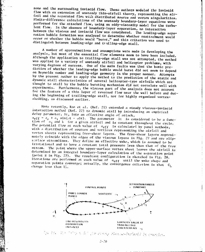
More recently, Rao et al. (Ref. 21) extended a steady vlscous-invlscid
interaction method (Ref. 22) to d%mamlc stall by introducing an empirical
delay parameter, AT, fnto ;Illeffective angle of attsck,
aeff = "_o + al sla(..'t - _,,AT). Tile parameter AI is considered to be a func-
tion of ,a_ and k for a given airfoil and is constant throughout tile cycle.
Tile potential flow at each value of _aeff is calculate'] by panel methods,
with a distributio_l of sources and vortices representing tile airfoil and
vortex sheets representing free-shear layers. The free-shear layers arJproxi-
mately coincide with tile edges of tile viscous layers in Fig. 27 aud are sllp-
s ,.rface stream|lass. They define all effective wake, which is assumed to be
[rrotatloaal and to have a constaot total pressure less than that ,_f the free
stre_ml. The polar where the upper-surface vortex sheet leaves the airfoil is
determined by all integral bouodary-hlyer calculation of tile separation point
(point S ill Fig. 27). The resultant configuration is sketched Ill Fig, 28.
Iterations are performed at each wthle of aef f until the wake shilpe and
st_p_tt'atiou points converge; actually, tile convergence criterion is that CL
ch:mge h'ss than 1.'_.
StPAItATION PANEl S't. CONTROLPOIN_'S _ ceNSTAN1
! POIN]:; I _ . -/
I I "
IINt ,1}I _l|l | let I _ % ON1 II'W1%" VALll[ AT
DIS1 IIl_ltll ION 1 _All I_tl I 11(31
tlNI*j_NI I.N IO'_'_tRglIItlACI _l
..-_0
-" 1981011501-TSB10"
•-' Although realistio hysteresis loops of CL and C_! versus a have been_ calculated, the results published so far (Ref. 21) cannot be considered pro-
dictive because they depend heavily on the arbitrary choice of A_. And as in
the analysis of Crlmi and Reeves (Re|. 20), neither the special festuroe of
unsteady reversed flow nov strong vertex shedding have been included, floweret,
with additional modifications and refinements, these zonal methods could offer
a reasonable balance of rigor, accuracy, and computational efficiency, at
least for light dynamic stall.
5.3 Navier-Stokes Calculations
Tllc limitatlons and approximations of zonal methods and the questions of
unsteady separation models can, in prinolple, be avoided by solving the full
Navier-Stokes equations. However, turbulence must be modeled and a number of
computational difficulties must be overcome if this approach is to be realisticfor most practical applications,
Several recently developed methods for laminar flows, discussed in Refs. Ito 4, have shed considerable light on the physical mechanisms of deep dynamic
stall at low Reynolds numbers and have lald the computational foundations for
high-Reynolds-ntmaber solutions of the so-called Reynolds-averaged, Navier-Stokes equations. For Incompressible flow in two dimensions, they may be
expressed as:
= o (l)
Vp + v\':_ - _ (2)1
J
where q represents tilevelocity vector (u,v) time-averaged over an interval
short with respect to the time scale of tile motion, but long with respect to
the time scale of the turbulence, and -PUiU i is tileReyamlds stress due totile random turbulent fluctuations. _he Reyn_Ids stress term vanishes iu
laminar flow and is to be modeled (empirically or otherwise) in tile turbulent
case. The particular representation of the detailed pbyslcs of turbulence is
crucial in many steady-flow problemls that are dominated by viscous effects.
tlowever, the importance of turbulence modeling fu dynamic stall has yet to beestablished.
Ntuaerica| codes tsshlg varioss turbtllesce models that have been developed_or steady flow are curretltly under developmeut at several research centers.A few very preliminary results have been published (Refs. 23, 24) and morew! II become available in the near future. However, quite apart from the qtleS-ties of the large computational times anti storagt.s required, tt will be sometime before these codes are adequately tested and verified. Nevertheless, tilt"
.. eart.f,l aml selective analysis of new numerical res,lts fer both light anddeep dyuamte stall will be especially beneficial in guidiug tile developmeat ofmol'e approximate elll_|.aeerill}', analyses and prediction methods b_lsed ea emp[ricsl
"" t'orrt.lat_ollS of _¢]lld-tulluel d_lta.
_-_ q.4 I._npirlcal Correlatlou 'rechniqne._
i The he l [copter iodn:;t ry ba_; dt.vt'lept.d severs] eut;tnet.rhH; predict[oil
fet'bnltlnes bilst'd on emplrtt'al correlstioes t_l wtnd-ttmuel dal[! for estlmatlugt|lt" tlnsteadv airier|d:; t_e o._cillatiug _lll'|oils. 'rhese rlethods seek tO corre-I.|tt! [orce aud mOmellt d.l|:l obLaiued Ii'o:z_ lelatively sll!lple wiDtl-tunnl?l |t.Ntt_
_ il_ |-Ol_ltl].ll Iollr; th.ll t_|low|be t.ffet'l_: oI tilL' nenlt'retl:_ t'elev;llll parameters
2-21
1981011501-TSB11
::. such as airfoil shape, Mach number, amplitude and frequency of oscillations,: mean angles and type of motion.
Common to all the available literature relevant to dynamic stall is the
;:J" observation that unsteady effects increase with increasing pitch rata, that
- is, rate of change of airfoil incidence. It is also evident that the dynamic
.= stall events require finite times to develop, Therefore, some form of =he__ ...... dimensionless parameters _c/Uoo and U_&t/c appears in all of the empirical
methods. A_oth_r co.on aspect is that the ampitlcal correlations are used as
corrections to steady airfoil data, so that most geometrical, Reynolds m_ber,
and Mach number effects are only accounted for insofar as they determine the_- static section eharaeteristlcs.
_._i The highlights of several methods currently in use by the helicopter
_: industry are outlined below. More detailed accounts of each can be found inthe references cited and in Refs. 2 to 4,
5.4. l Boeing-Vet:el gamma function method (Refs. 25, 26)- The onset oZ
_i dynamic stall is assumed to occur at aDS = + daD, where aSS is theaSS
static stall angle and daD = 7_ec_p_/u_.The quantity y, which is the essen-tial empirical function, depends on airfoil geometry and Mach number and is
__ different for lift and moment stall. The gamma functions were generated froma large amount of data generated in a transonic wlnd-tunnel test of various
airfoils oscillating sitmsoidally in pitch. The force and moment coefficients
i are constructed from static data using an equivalent angle of attack that
accounts for unsteady potential-flow effects, _eq' and a reference angle.ar = a +-y_,* as follows:
_ [aeql%]Cl(%)}
T_ Cl"ar based on )lift
_ CD _ CD(t_r) (3)
CM = [0.25 - Xcp]C L
The location of the aerodynamic center of pressure, Xe , is specified empiri-Ptally in the current version of the method. This formulation permits a
dynamic overshoot of CL above its maximum static value, but not of CD."
Also, note that aDS in always less than _max' since A_xD = 0 when ,x= 0.
5.4.2 UTRC t_, A, B method (Rcfs. 27, 28)- A table-lookup correlation
method, which has recently been synthesized into a more str.-m_lined format,
was developed at United Technologies Research Center to determine CI, and CMfrom three independent par_mleters of tile airfoil motion. The choice of theparameters was inspired by thin-airfoil potential theory; they are instant;m-
cons incidence n(t), angular velocity parameter A = _xc/2U_, and angular
lurati_n parameter B = _e'/4£m _. It is interesting to note that theseaccc • _ " l _
thrcc pa)'ameters are sufficient to define to engtneertag accuracy the matetE[ng_l(t) histories for the two cast, s shown in Fig. 17. Tile data base for tileempirical correlations came from experiments on an NACA 0012 airfoil oscillat-ing in pitch at M 5 0.3, including both steusotdal and nonstuusoidal motion.None of the data attained the extreme values that have bccn observed to
accompany the fully developed vortex-shedding phenontenon of deep stall.
5.4.3 FlIT method (Ref. 29)- Thi,'; method i:_ basically an • _ ", 1_m I iric'l repre-
_entatiell of the for,.'ll.q and momeete due to the vorte.x-shcddtllg phenome_lon for
ramp changes in angle of attack. The actual angle of dynamic stall must be
• _he !_|gn el the retail.el telTx_ It; takcl_ to be t_ppo:_lte to t.ht, ._[}',l_ of ,'t,
2-22
,,, _ I I I
1981011501-TSB12
specified separately; the value aDS - aSS + 3° has normally been uRed. ForE aSS < _ < aDS, the data are extrapolated _rom below static stall, Starting _t
a - aDS, CL and CM are assumed to increase linearly with time over a speci-fied time interval, from invlscid values to peak values that depend on _c/U_
at the instant of dynamic stall. If this is attained before a - =max, then
CL and CM remain constant tlntll _aax' They decay exponentlally* with pre-assigned time constants thereafter until the static stall values are attained.
These new values are ratalnsd until a m aSS on the downstroke, when theunstalled static section characteristics are reattained.
,_ 5.4.4 Lockheed method _Refs. 30 r 31)- This combined analytical andempirical modeling of dynamic stall incorporates phass-l_g time constants and
pltch-rate-dependent, stall-angle delay increments into a fictlclous effective
_,_ angle of attack. This effective angle is used to construct CL and CM fromh<
,_ static airfoil characteristics and a linear combination of _number of sepa-
• rate dynamic stall elements. Some of these elements are assumed to be analo-
l_ gous to flow phenomena that have been treated elsewhere in the literature,
, such as leadlng-edge Jets, the lag in circulation buildup on a pitching air-foil in potential flow, separation over moving walls, fluctuating pressure
propagation in turbulent boundary layers, and the vortex llft due to leading-
edge vortices on delta wings. Other elements are modeled directly from
dynamic stall measurements on oscillating airfoils. In this sense, the
method has more degrees of freedom than any of the others, and information
from many sources has been utilized.
At low frequency, the phase lag of the effective incidence is linearly
proportional to k. The latest version (Ref. 31) includes increments of CLand CM due to the vortex-sheddlng phenomenon that are proportional tosin 2 a. Compressibility corrections are developed from various arplicatlonsof the Prandtl-Glauert rule. This is the only method which distinguishes
between pitching and plunging motion.
5.4.5 Time-delay methods (Refs. 4, 32)- The basic idea of this approachis that each dynamic stall event is governed by a separate uni'¢ersal dimen-
sionless time constant of the form r _ U=At/c, regardless of the time history
of the motion; T may be identified with the parameter s - 2U_t/c, which is
fundamental to expressions for the indicial aerodynamic response in the
attached-flow regime. The construction of the force and moment characteris-
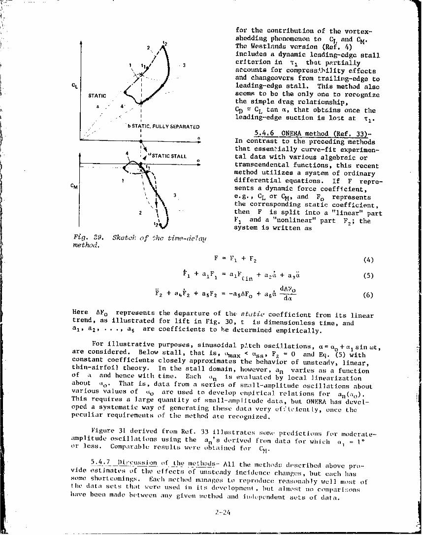
tics can be explained with the aid of Fig. 29. If tu is the tilae at which
the angle of attack passes through aSS, then moment stall begins at time
tI = to + _Ic/U_ and CLmax occurs at t 2 = to + T2c/U _. For t < tI
(llne segments I in the figure), the values of CL and CM are taken from
unsteady potential theory. For tI < t < t2, CL continues this trend, butthe aerodynamic center of pressure moves rearward along the locus of the static
curve of Xcp versus _. Therefore, -CM increases along line segment 2 accord-
ing to the relation CM = (0.25 - Xcp)C L during this time interval.
After lift stall at t = t2' CL decreases by an empirical exponential
law with respect to time, whereas CM is calculated from the same relation
as before. Line segments 3 terminate at _ = oSS and at a value of CLthat corresponds to a fully separated approximation, indicated in Fig. 29.
The return to minimum incidence, llne sea,eats 4, is governed by still otherexponential functions.
The Sikorsky version (Ref. 32) now uses the values rI = 2.5 and
za = 5.0 for the time constants. It makes no provision for compressibillty
phenomena other than in the static characteristics for CL(U) and Xcp(_), nor
*A linear decay over a time interval h¢0t , 0.2 has also been used.
2-23
-- ii[ I II II II I
,w .--
4.
fe_ the contribution of the vortex-
shedding ph(momenon to Of. and C_4.
The Wcstlands vcrslon (Ref. 4)
;_ 2/i includes a dynamic leadlng-edgo stall
_i_ criterion in "r.t that p.-.rtlaily
i l\ t 1 / 3 accounts for compressibility effects
and changeovers from traillttg-edge to
i eL / :f. leading-edge stall. Tills method also
I ff ', / seems to be tile only one to reeognlze- STATIC . _ the simple drag relationship,
a " 4". t] CD _ CL tan _, that obtains once the
/ , _ leadlng-edge suetlon is io_t at TI.
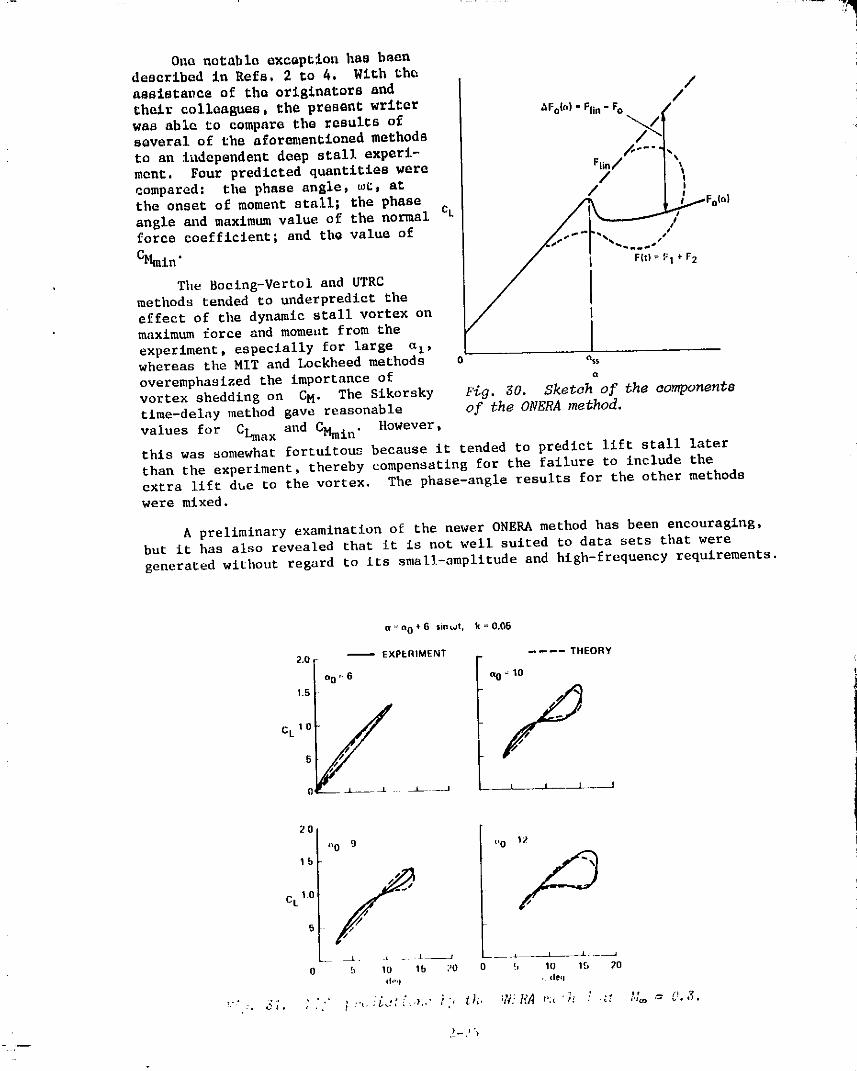
/ bSTATIC.FULLY SEPARATED' , 5.4.6 ONERA met ho d (Ref. 33)-
I _"" ' _ In eo'ntrast to the preceding methods
_ that essentially curve-flt experlmen-
4 ',4_STATICSTALL tal data with various algebraic or
_ _ transcendental functions, this recent
..... t_ method utilizes a system of ordinary
differential equations. If F repre-
cM _",__ I sents a dynamic force coeffielent_
_ '_1, 3 e.g., CL or CH, and Fo represents' the corresponding static coefficient,
2 % _. then F is split into a "linear" parti _ F I and a "nonlinear" part F 2 ; the
t
2%_ system is written as
Fig. ,?,°9. Sketei: of "Jhc t_me-de_a[_method.
F = F I + F2 (4)
_i + alF l = azFci n + a2& + a_ (5)
dA_o
F2 + 8_F2 + asF2 = -abAFo + as& dtx (6)
Here AF o represents the departure of the 8tttt[c coefficient from its lineartrend, as illustrated for llft in Fig. 30, t is dimensionless time, and
al, a 2, . .., a s are coefficients to he determined empirically.
For illustrative purposes_ sinusoidal p'.tch oscillations, _= ao + a I sin _t,
are considered. Below stall, that is, thnax < ass, Fz = 0 and Eq. (5) with
constant coefficients closely approximates the behavior of unsteadv_ linear,
thln-alrfoil theory. In the stall domain, however, an varies as a function
of ,a and hence with time. Each 'Xn is ex,aluated by local linearizatlon
about a o. That is, data from a series of sm;_ll-amplitudc osclllatlons about
varlous values of tie arc used to develop empirical relations for an(So).
Thls requires a large quantity of small-amplitude data, but ONERA has devel-
oped a systematic way of generating these data very efficiently, once tile
peculiar requlremeuts of the method ate recoguJzed.
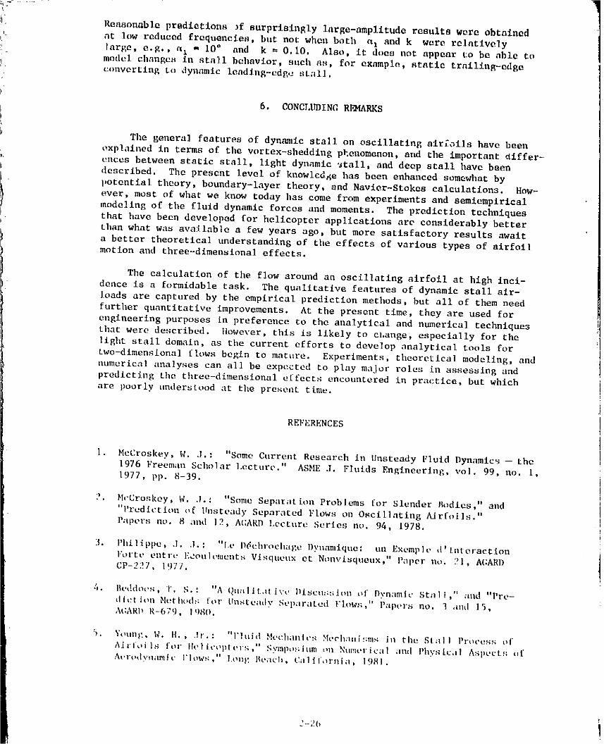
Figure 31 derived from Ref. 33 Illustrates semi. predlcthms for moderate-
amplitude oscillations using the an's derived from data for which (_] = I°
or less. Comparable results wt,re obtailled for CH.
5.4.7 Dt!'cussion of tilt,methods- All tile method!:: described above pro-
vide estimates t,f tile effects of unsteady Incidence chaugt_s, hut each has
some shortcemin|'.s. Each method manatees to rel)t'odt_ce reasonably well most of
the data sets that were used in its dt, velopmel_!, l_ut alme_t: ZlO comparir;ons
have heen made h_qween auy given method and _dt:pendel_t sets of dal a.
2-24
1981011501-TSB14
One notable excuption has beendescribed in Refs, 2 to 4. gich the
aeeistavce of the originators and /
thelv colleagues, the present writer _Fol.)._lin__ /was able to compare the results of _ ]several of the aforementioned methods
to an independent deep stall experi- _ ....ment. Four predicted quantities were Flin/ _
compared: the phase angle, _t, at /the onset of moment stall; the phase / '
force coefficient; and the value of
_|mie" = :
The Boeing-Vertol and UTRCmethods tended Co underpredict the
effect of the dynamic stall vortex onmaximum force and mome,tt from the
experiment, especially for large _i,whereas the MIT and Lockheed methods %overemphasized the importance of o
vortex shedding on CM. The Sikorsky _g. 30. Sketah of the ao.vlponentgtime-delay method gave reasonable of the ONERA _ethod.
values for CLmax and CMmin. However,
this was somewhat fortuitous because it tended to predict lift stall later
than the experiment, thereby compensating for the failure to include the
extra lift due to the vortex. The phase-angle results for the other methodswere mixed.
A preliminary examination of the newer ONERA method has been encouraging,but it has also revealed that it is not well suited to data sets that were
generated without regard to its small-amplitude and high-frequency requirements.
_n0+6 _in_Jt, k=0,G5
2.0 -- EXPERIMENT .... THEORY
_0 _ 6 e0 _ _0
1+5 f
CL105 j
2O
o0 9 _'0 12
CL l0 _ s
b 10 15 20 !+ lO 15 20¢h"l , ¢leq
+_-- ,I rI
1981011501-T.q('t.n'
:1[ Reasonable predictions Jf surprisingly large-amplitude results were obtained
_ at low reduced frequencies, but not when both a a and k were relatively
large, e.g., a x ,, 100 and k = 0,10. Also, it does not appear to be able temodel changes in stall behavior, such as, for exampl_, statle traillng-edge
[I. coaver_ing to dynamic leadlng-edgo stall.
6. CONCLI_)INC RFLMARKS
The general features of dynamic stall on oscillating airfoils have been
oxplalned in terms of the w_rtex-sheddlng phenomenon, and the important differ-.
ences between stagic stall, light dynamic 'stall, and deep stall have been
described. The present le_cl of knowledge has been enhanced somewhat by
- potential theory, boundary-layer theory, and Navier-Stokes calculations. How-ever, most of what we know today has come from experiments and semlempirlcal
modeling of the fluid dynamic forces and moments. The prediction techniques
I that have been developed for helleopter applications are considerably better
Ehan what was available a few years ago, but more satisfactory results await
a better theoretical understanding of the effects of various types of alrfoilmotion and three-dimensional effects.
The ca]culation of the flow around an oscillating airfoil at high inci-
dence is a formidable task. The qualitative features of dynamic stall air-loads are captured by the empirical prediction methods j but all of them need
further quantitative improvements. At the present time, they are used for
engineering purposes in preference to the analytlcal and numerical techniques
that were described. }lowever, this is likely to change, especially for the
light stall domain, as the current efforts to develop analytical tools for
two-dimensional flows begin to mature. Experiments, theoretical modeling, and
aumerical analyses can all be expected to play major roles in assessing and
predicting the three-dimensional effects encountered in practice, but which
are poorly understood at the present time.
REFERENCES
I. McCroskey, W. J.: "Some Current Research in Unsteady Fluid Dynamic_ -- the
1976 Freeman Scholar Lecture." ASME J. Fhilds EngineerJag, col. 99, no. l,
1977, pp. 8-39.
2. HcCroskey, W. 3." "Some SeparatEon Problems [or Slender Bodies," and
"1'rudlctloa of Unsteady Separated Flows on Oscil]ating A/flails."
Papers no. 8 and ]2, Ai;ARD Lecture Series no. 94, 1978.
3. Pht|ippe, .1. .1.; "l.e I*_ehrt',cha_,e Dynamique: tin Exemplt. d'[nteractionI:ortt.cntl-c Ecoulements Vlsqttuux et Ntnlvisqueux," P;iper no. [_I, A(;ARI)CP-227, 1977.
4. Bt.ddot's, T. S.: "A QllalJtdti\'t' Dlseus:;hnl of Dyn;Imtt' Stnll," aad "Pre-
tllt:t ion bltrtht>(t._; |or Uosteady Sep;iratet| |'low._;, '' P;ipers co. ] ;Hid 15,At;AR|_ R-679, I qS(%.
5. Yoell}'_, W. H., .tr.: "V]uid Hechde|cs Ht,challJf;nl_ Jl1 tile Stall Process ofAil loils for Ih, licoptt, r!¢," Syl:lpo._;iHm t,a NHmt, l'Jc;ll lind P]lys[c,l| Aspects _,fA_q-ody_anmlc View.q," long Beach, ¢._ill]l/_YllJil, 1981.
.'_-2b
1981011501-TSC02
................. q
6. McAlieter, K. W.; and Cart, L. W.: "Water-Tunnel Experiments on an
Oscillating Airfoil at Re - 21000," NASA I_-78446, 1978.
7. McCroakey, W. J.; Cart, L. W.; and McAlister, K. W.: "Dynamic Stall
Experiments on Oscillating Airfoil0, e J, A!AA. vol. 14, no. I, 1976,
pp. 57-63.f_-
i_ 8. McCroskey, W. J., et al.: "Dynamic Stall on Advanced Airfoil Sections,"American Helicopter Society Preprlnt 80-01, 1980.
9. McCroskey, W. J.; Pucci, S. L.: "Viscous-lnviscld Interaction on Oscil-
lating Airfoils in Subsonic Flow," AIAA Paper 81-0051, 1981.
I0. Liiva, J.: "Unsteady Aerodynamics and Stall Effects on Helicopter Rotor• Blade Sections." J. Aircraft, vol. 6, no. i, 1969, pp. 46-51.
ii. Maresca, C.; Favler, D.; and Rebont, J.: "Unsteady Aerodynamics of an
Airfoil at High Angle of Incidence Performing Various Linear Oscillations
| in a Uniform Stream." Paper no. 12, Fifth European Rotorcraft and
..... Powered Lift Aircraft Forum, Amsterdam, Netherlands, 1979.
I 12. Fukushima, T.; and Dadone, L. U.: "Comparison of Dynamic Stall Phenomena
.... for Pitching and Vertical Translation Motions." NASA CR-2793, 1977.
13. Carta, F. O.: "A Comparison of the Pitching and Plunging Response of an
Oscillating Airfoil." NASA CR-3172, 1979.
14. St. llilaire, A. O.; Carta, F. O.; and Jepson, W. D.: The Influence of
Sweep on the Aerodynamic Loading of an Oscillating NACA 0012 Airfoil."
AHS Preprlnt 79-4, 1979.
15. McCroskey, W. J.; and Fisher, R. K., Jr.: "Detal]ed Aerodynamic Measure-
ii manta on a Model Rotor in the Blade-Stall Regime." J. AHS, vol. 17, no. i,1972, pp. 20-30.
! 16. Ham, N. D.: "Aerodynamic Loading on a Two-Dimenslonal Airfoil during
_ Dynamic Stall." J. AIAA, vol. 6, no. }0, 1968, pp. I_27-1934.
17. Baudu, N.; Sagner, M.; and Souquet, J.: "Modoliaation du D4ehrochage
Dynamlque d'un Profil Oscillant." AAAF 10th Colloque d'A4ronautlque
Appliqu4e, Lille, France, 1973.
18. Glesing, J. P.: "Nonlinear Two-Dimenslonal Potential Flow with lift."
.I. Aircraft, vol. 5, no. 2, 1968, pp. 135-143.
19. One, K.; Kuwahara, K.; and Oshlma, K.: "Numerical Analysis of Dynamic
Sial] Phenomena of an Osclllatlng Airfoil by the Discrete Vortex Approxi-
matlon." Paper no. 8, Seventh Internatlona] Conference on Numerical
Metl'_ds lu Fluid Dynamics, Stanford, California, !980.
20. CrlmJ, P.; and Reeves, B. L.: "A Method for Analyzing Dynamic Stall of
Helicopter Rotor B]ades." NASA CR-2009, 1972; also NASA CR-2335, 1974.
21. Rao, B. H.; Maskew, 8.; and Dw>rak, F. A.: "Theoretical Prediction of
Dynamic Stall on Oscillating Airfoils," AIIS Paper 78-62, 1978.
i!2. Haskew, B.; and Dvorak, F. A.: "Investigation o| Separ;itlon Models for
the ]'rodit'tton of Cl_ax." .1. AIiS, vol 23, no. it, 1978, pp. 2-8.
2-27
1981011501-T8C03
23. Shamroth, S. J. ; and Gibcling, H. J." "The Prediction of the TurbulentFlow Field about an Isolated Airfoil." AIAA Paper 79-1543, 1979_ alsoNASA CR-3183, 1979.
24, Sugavanum, A._ and Wu, J. C." "Nluaerical Study of S_parated Turbulent
Flow over Airfoils." AIAA Paper 80-1441, 1980.
25. l_arria, F. D.; Tarzanin, F. J., Jr.; and Fisher, R. K., Jr.: "Rotor
IIigh-Speed Performance; Theory vs Test." J. /diS, vol, 15, no. 3, 1970,
pp. 35-44.
26. Cormont, R. E.: "A Mathematical Model of Unsteady Aerodynamics and
Radial Flow for Application to Helleopter Rotors." U.S. Army AMRDL-
Eustis Directorate Report TR-72-67, 1973.
27. Carta, F. O, et al.: "Investigation of Airfoil Dynamic Stall and Its
Influence on Helicopter Control Loads." U.S. Army AMRDL-Eustis Director-ate Report TR-72-51, 1972.
28. Bielawa, R. L." "Synthesized Unsteady Airfoil Data with Applications to
Stall-Flutter Calculations." AIIS Preprint no. 935, 1975,
29. Johnson, W. : "The Effect of Dynamic Stall on tile Response and Airloadlng
of Relicop[er Rotor Blades." J. /diS, vol. 14, no. 2t 1969, pp. 68-79.
30. Ericsson, L. E, ; and Reding, J. P. : "Dynamic Stall Anal3"=_s in _he Light
of Recent Numerical and Experimental Results." J. Aircraft, vol. 13,
no. 4, 1976, pp. 248-255.
31. Ericsson, L. E.; and Reding, J. P.: "Dynamic Stall at Nigh Frequency
and Large Amplitude." J. Aircraft, vol. 17, no. 3, 1980, pp. 13b-142.
32. Carlson, R. G. et el.: "Dynamic Stall Modeling and Correlation withExperimental Data on Airfoils and Rotors." Paper no. 2, NASA SP-352,1974.
33. Tran, C. T.; and Petot, D.: "Semi-Empirical Model for the Dynmnic Stallof Airfoils in View of tile Application to the Calculation of Responses
of a llelicopter Blade in Forward Flight." Paper no. 48, Sixth EuropeanRotorcraft and Powered-Lift Aircraft Forura, Bristol, England, 1980.
,,_?,q
1981011501 -TSC04