Embed Size (px)
Citation preview

The Physical LayerChapter 2
CN5E by Tanenbaum & Wetherall, © Pearson Education-Prentice Hall and D. Wetherall, 2011
• Theoretical Basis for Data Communications• Guided Transmission Media• Wireless Transmission• Communication Satellites• Digital Modulation and Multiplexing• Public Switched Telephone Network• Mobile Telephone System• Cable Television
Revised: August 2011
CN5E by Tanenbaum & Wetherall, © Pearson Education-Prentice Hall and D. Wetherall, 2011
The Physical Layer
Foundation on which other layers build• Properties of wires, fiber, wireless
limit what the network can do
Key problem is to send (digital) bits using only (analog) signals• This is called modulation
Physical
Link
Network
Transport
Application

Theoretical Basis for Data Communication
Communication rates have fundamental limits
• Fourier analysis »• Bandwidth-limited signals »• Maximum data rate of a channel »
CN5E by Tanenbaum & Wetherall, © Pearson Education-Prentice Hall and D. Wetherall, 2011
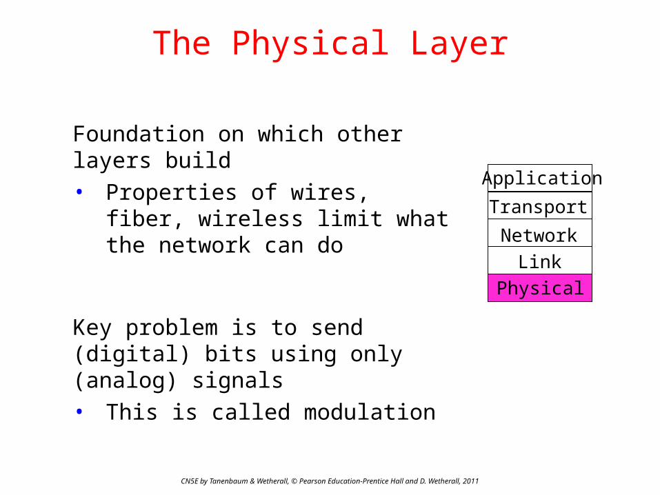
Fourier Analysis
A time-varying signal can be equivalently represented as a series of frequency components (harmonics):
CN5E by Tanenbaum & Wetherall, © Pearson Education-Prentice Hall and D. Wetherall, 2011
a, b weights of harmonicsSignal over time
=

CN5E by Tanenbaum & Wetherall, © Pearson Education-Prentice Hall and D. Wetherall, 2011
Bandwidth-Limited Signals
Having less bandwidth (harmonics) degrades the signal
8 harmonics
4 harmonics
2 harmonics
Lost!
Bandwidth
Lost!
Lost!
CN5E by Tanenbaum & Wetherall, © Pearson Education-Prentice Hall and D. Wetherall, 2011
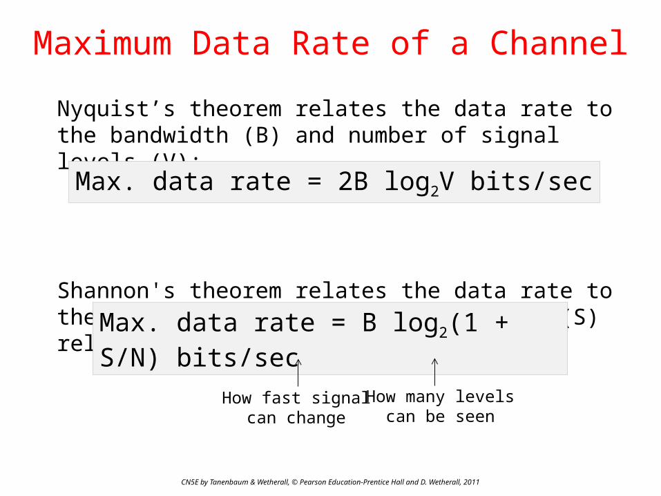
Maximum Data Rate of a Channel
Nyquist’s theorem relates the data rate to the bandwidth (B) and number of signal levels (V):
Shannon's theorem relates the data rate to the bandwidth (B) and signal strength (S) relative to the noise (N):
Max. data rate = 2B log2V bits/sec
Max. data rate = B log2(1 + S/N) bits/sec
How fast signalcan change
How many levelscan be seen

CN5E by Tanenbaum & Wetherall, © Pearson Education-Prentice Hall and D. Wetherall, 2011
Guided Transmission (Wires & Fiber)
Media have different properties, hence performance• Reality check
− Storage media »
• Wires:− Twisted pairs »− Coaxial cable »− Power lines »
• Fiber cables »
CN5E by Tanenbaum & Wetherall, © Pearson Education-Prentice Hall and D. Wetherall, 2011
Reality Check: Storage media
Send data on tape / disk / DVD for a high bandwidth link• Mail one box with 1000 800GB tapes (6400 Tbit)• Takes one day to send (86,400 secs)• Data rate is 70 Gbps.
Data rate is faster than long-distance networks!
But, the message delay is very poor.

CN5E by Tanenbaum & Wetherall, © Pearson Education-Prentice Hall and D. Wetherall, 2011
Wires – Twisted Pair
Very common; used in LANs, telephone lines• Twists reduce radiated signal (interference)
Category 5 UTP cable with four twisted pairs
Link Terminology
CN5E by Tanenbaum & Wetherall, © Pearson Education-Prentice Hall and D. Wetherall, 2011
Full-duplex link• Used for transmission in both directions at once• e.g., use different twisted pairs for each direction
Half-duplex link• Both directions, but not at the same time• e.g., senders take turns on a wireless channel
Simplex link• Only one fixed direction at all times; not common

CN5E by Tanenbaum & Wetherall, © Pearson Education-Prentice Hall and D. Wetherall, 2011
Wires – Coaxial Cable (“Co-ax”)
Also common. Better shielding and more bandwidth for longer distances and higher rates than twisted pair.
CN5E by Tanenbaum & Wetherall, © Pearson Education-Prentice Hall and D. Wetherall, 2011
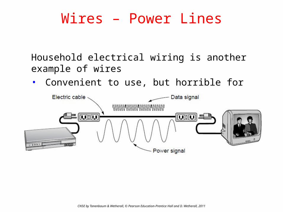
Wires – Power Lines
Household electrical wiring is another example of wires• Convenient to use, but horrible for sending data
CN5E by Tanenbaum & Wetherall, © Pearson Education-Prentice Hall and D. Wetherall, 2011
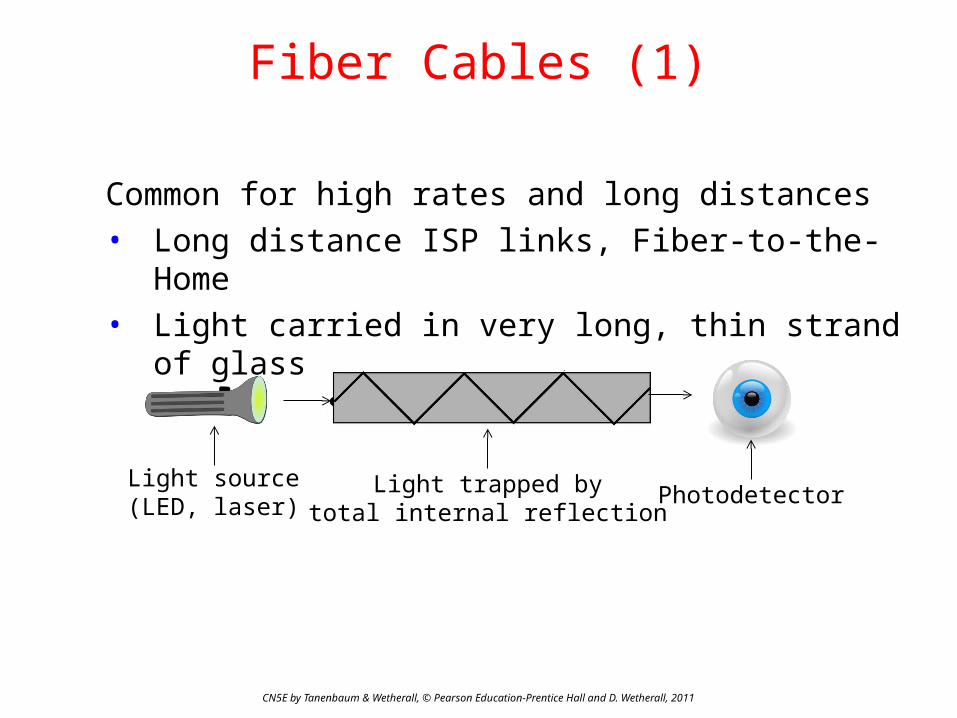
Fiber Cables (1)
Common for high rates and long distances• Long distance ISP links, Fiber-to-the-Home• Light carried in very long, thin strand of glass
Light source(LED, laser) PhotodetectorLight trapped by
total internal reflection

Fiber Cables (2)
CN5E by Tanenbaum & Wetherall, © Pearson Education-Prentice Hall and D. Wetherall, 2011
Fiber has enormous bandwidth (THz) and tiny signal loss – hence high rates over long distances

CN5E by Tanenbaum & Wetherall, © Pearson Education-Prentice Hall and D. Wetherall, 2011
Fiber Cables (3)
Single-mode• Core so narrow (10um) light
can’t even bounce around• Used with lasers for long
distances, e.g., 100km
Multi-mode• Other main type of fiber• Light can bounce (50um core)• Used with LEDs for cheaper,
shorter distance linksFibers in a cable

CN5E by Tanenbaum & Wetherall, © Pearson Education-Prentice Hall and D. Wetherall, 2011
Comparison of the properties of wires and fiber:
Fiber Cables (4)
Property Wires Fiber
Distance Short (100s of m) Long (tens of km)
Bandwidth Moderate Very High
Cost Inexpensive Less cheap
Convenience Easy to use Less easy
Security Easy to tap Hard to tap
CN5E by Tanenbaum & Wetherall, © Pearson Education-Prentice Hall and D. Wetherall, 2011
Wireless Transmission
• Electromagnetic Spectrum »• Radio Transmission »• Microwave Transmission »• Light Transmission »• Wireless vs. Wires/Fiber »

CN5E by Tanenbaum & Wetherall, © Pearson Education-Prentice Hall and D. Wetherall, 2011
Electromagnetic Spectrum (1)
Different bands have different uses:− Radio: wide-area broadcast; Infrared/Light: line-of-sight − Microwave: LANs and 3G/4G;
Microwave
Networking focus

CN5E by Tanenbaum & Wetherall, © Pearson Education-Prentice Hall and D. Wetherall, 2011
Electromagnetic Spectrum (2)
To manage interference, spectrum is carefully divided, and its use regulated and licensed, e.g., sold at auction.
Source: NTIA Office of Spectrum Management, 20033 GHz 30 GHz
3 GHz300 MHz
WiFi (ISM bands)
Part of the US frequency allocations
CN5E by Tanenbaum & Wetherall, © Pearson Education-Prentice Hall and D. Wetherall, 2011
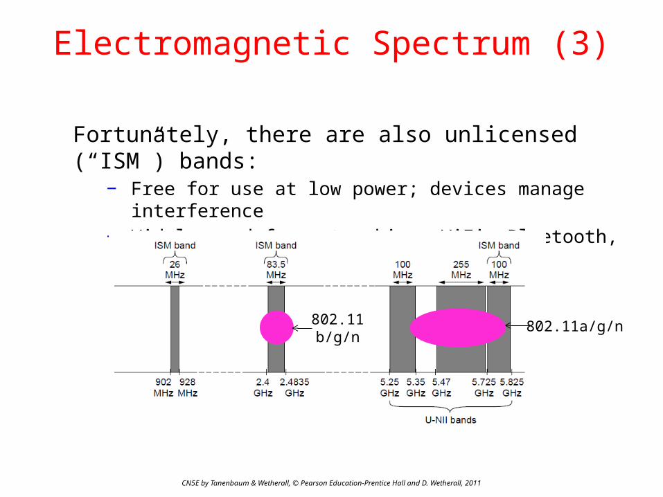
Electromagnetic Spectrum (3)
Fortunately, there are also unlicensed (“ISM”) bands:− Free for use at low power; devices manage interference− Widely used for networking; WiFi, Bluetooth, Zigbee, etc.
802.11b/g/n
802.11a/g/n
CN5E by Tanenbaum & Wetherall, © Pearson Education-Prentice Hall and D. Wetherall, 2011
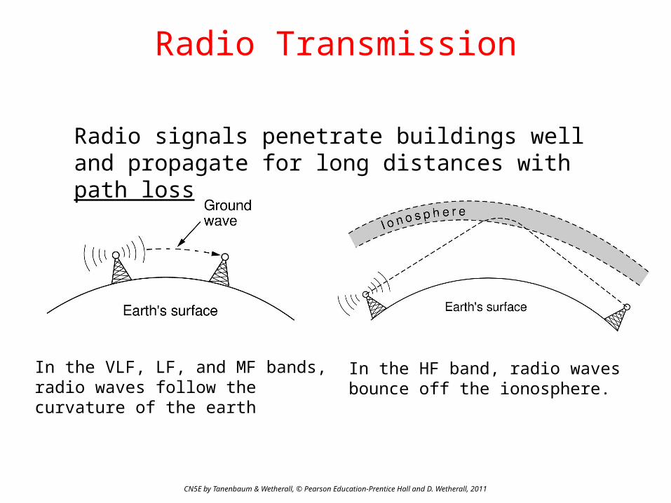
Radio Transmission
In the HF band, radio waves bounce off the ionosphere.
In the VLF, LF, and MF bands, radio waves follow the curvature of the earth
Radio signals penetrate buildings well and propagate for long distances with path loss
CN5E by Tanenbaum & Wetherall, © Pearson Education-Prentice Hall and D. Wetherall, 2011
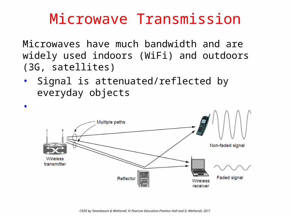
Microwave Transmission
Microwaves have much bandwidth and are widely used indoors (WiFi) and outdoors (3G, satellites)• Signal is attenuated/reflected by everyday objects• Strength varies with mobility due multipath fading, etc.

CN5E by Tanenbaum & Wetherall, © Pearson Education-Prentice Hall and D. Wetherall, 2011
Light Transmission
Line-of-sight light (no fiber) can be used for links• Light is highly directional, has much bandwidth• Use of LEDs/cameras and lasers/photodetectors
Wireless vs. Wires/Fiber
CN5E by Tanenbaum & Wetherall, © Pearson Education-Prentice Hall and D. Wetherall, 2011
Wireless:+ Easy and inexpensive to deploy+ Naturally supports mobility+ Naturally supports broadcast− Transmissions interfere and must be managed− Signal strengths hence data rates vary greatly
Wires/Fiber:+ Easy to engineer a fixed data rate over point-to-point links− Can be expensive to deploy, esp. over distances− Doesn’t readily support mobility or broadcast

CN5E by Tanenbaum & Wetherall, © Pearson Education-Prentice Hall and D. Wetherall, 2011
Communication Satellites
Satellites are effective for broadcast distribution and anywhere/anytime communications
• Kinds of Satellites »• Geostationary (GEO) Satellites »• Low-Earth Orbit (LEO) Satellites »• Satellites vs. Fiber »

CN5E by Tanenbaum & Wetherall, © Pearson Education-Prentice Hall and D. Wetherall, 2011
Kinds of Satellites
Satellites and their properties vary by altitude:• Geostationary (GEO), Medium-Earth Orbit (MEO),
and Low-Earth Orbit (LEO)
Sats needed for global coverage
CN5E by Tanenbaum & Wetherall, © Pearson Education-Prentice Hall and D. Wetherall, 2011
Geostationary Satellites
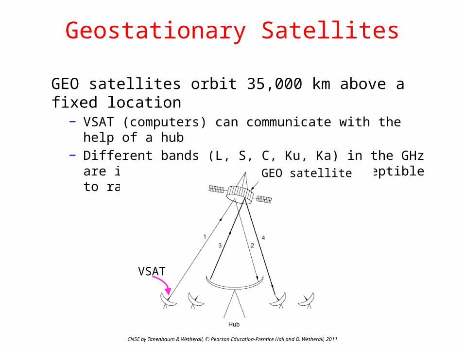
GEO satellites orbit 35,000 km above a fixed location− VSAT (computers) can communicate with the help of a hub− Different bands (L, S, C, Ku, Ka) in the GHz are in use but
may be crowded or susceptible to rain.
VSAT
GEO satellite

CN5E by Tanenbaum & Wetherall, © Pearson Education-Prentice Hall and D. Wetherall, 2011
Low-Earth Orbit Satellites
Systems such as Iridium use many low-latency satellites for coverage and route communications via them
The Iridium satellites form six necklaces around the earth.

CN5E by Tanenbaum & Wetherall, © Pearson Education-Prentice Hall and D. Wetherall, 2011
Satellite vs. Fiber
Satellite:+ Can rapidly set up anywhere/anytime communications (after
satellites have been launched)+ Can broadcast to large regions− Limited bandwidth and interference to manage
Fiber:+ Enormous bandwidth over long distances− Installation can be more expensive/difficult

CN5E by Tanenbaum & Wetherall, © Pearson Education-Prentice Hall and D. Wetherall, 2011
Digital Modulation and Multiplexing
Modulation schemes send bits as signals; multiplexing schemes share a channel among users.
• Baseband Transmission »• Passband Transmission »• Frequency Division Multiplexing »• Time Division Multiplexing »• Code Division Multiple Access »
CN5E by Tanenbaum & Wetherall, © Pearson Education-Prentice Hall and D. Wetherall, 2011
Baseband Transmission
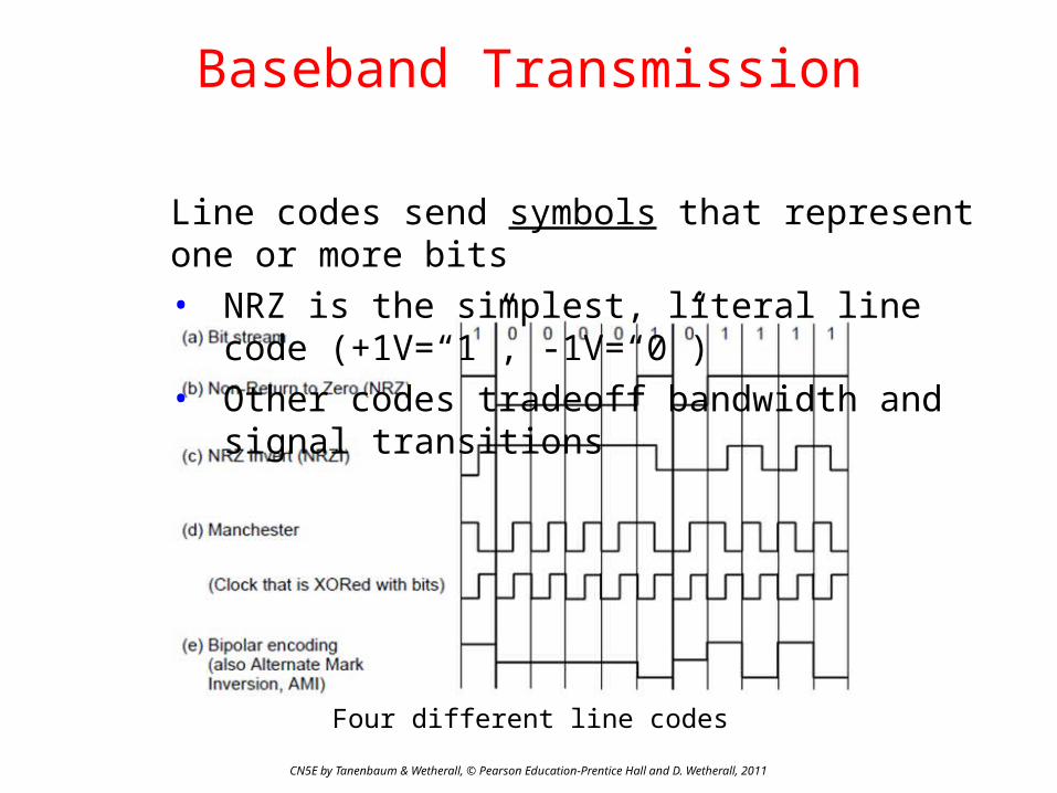
Line codes send symbols that represent one or more bits• NRZ is the simplest, literal line code (+1V=“1”, -
1V=“0”)• Other codes tradeoff bandwidth and signal
transitions
Four different line codes

Clock Recovery
To decode the symbols, signals need sufficient transitions• Otherwise long runs of 0s (or 1s) are confusing, e.g.:
Strategies:• Manchester coding, mixes clock signal in every symbol• 4B/5B maps 4 data bits to 5 coded bits with 1s and 0s:
• Scrambler XORs tx/rx data with pseudorandom bits
CN5E by Tanenbaum & Wetherall, © Pearson Education-Prentice Hall and D. Wetherall, 2011
1 0 0 0 0 0 0 0 0 0 0 um, 0? er, 0?
Data Code Data Code Data Code Data Code0000 11110 0100 01010 1000 10010 1100 110100001 01001 0101 01011 1001 10011 1101 110110010 10100 0110 01110 1010 10110 1110 111000011 10101 0111 01111 1011 10111 1111 11101

CN5E by Tanenbaum & Wetherall, © Pearson Education-Prentice Hall and D. Wetherall, 2011
Passband Transmission (1)
Modulating the amplitude, frequency/phase of a carrier signal sends bits in a (non-zero) frequency range
NRZ signal of bits
Amplitude shift keying
Frequency shift keying
Phase shift keying

BPSK2 symbols
1 bit/symbol
QPSK4 symbols
2 bits/symbol
QAM-1616 symbols
4 bits/symbol
QAM-6464 symbols
6 bits/symbol
QAM varies amplitude and phaseBPSK/QPSK varies only phase
Passband Transmission (2)
CN5E by Tanenbaum & Wetherall, © Pearson Education-Prentice Hall and D. Wetherall, 2011
Constellation diagrams are a shorthand to capture the amplitude and phase modulations of symbols:
CN5E by Tanenbaum & Wetherall, © Pearson Education-Prentice Hall and D. Wetherall, 2011
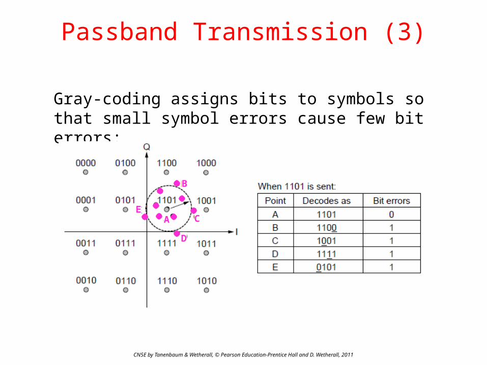
Passband Transmission (3)
Gray-coding assigns bits to symbols so that small symbol errors cause few bit errors:
A
B
C
D
E
CN5E by Tanenbaum & Wetherall, © Pearson Education-Prentice Hall and D. Wetherall, 2011
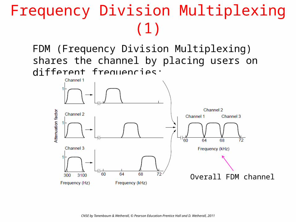
Frequency Division Multiplexing (1)
FDM (Frequency Division Multiplexing) shares the channel by placing users on different frequencies:
Overall FDM channel

CN5E by Tanenbaum & Wetherall, © Pearson Education-Prentice Hall and D. Wetherall, 2011
Frequency Division Multiplexing (2)
OFDM (Orthogonal FDM) is an efficient FDM technique used for 802.11, 4G cellular and other communications• Subcarriers are coordinated to be tightly packed
CN5E by Tanenbaum & Wetherall, © Pearson Education-Prentice Hall and D. Wetherall, 2011
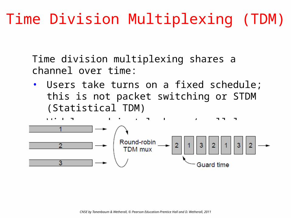
Time Division Multiplexing (TDM)
Time division multiplexing shares a channel over time:• Users take turns on a fixed schedule; this is not
packet switching or STDM (Statistical TDM)• Widely used in telephone / cellular systems
CN5E by Tanenbaum & Wetherall, © Pearson Education-Prentice Hall and D. Wetherall, 2011
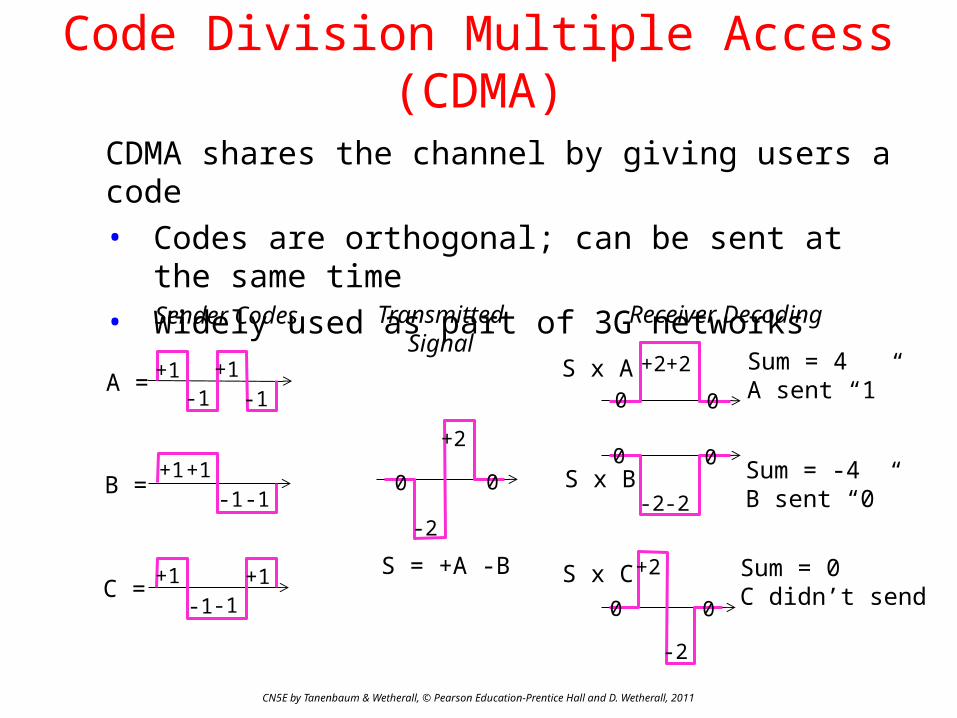
Code Division Multiple Access (CDMA)
CDMA shares the channel by giving users a code• Codes are orthogonal; can be sent at the same time• Widely used as part of 3G networks
A = +1-1
+1-1
B =+1 +1
-1 -1
+1 +1-1-1
C =
-2
+2
0 0
S = +A -B
S x A +2+2
-2-2
-2
+2
0 0
S x B
S x C
Sum = 4A sent “1”
Sum = -4B sent “0”
Sum = 0C didn’t send
Sender Codes TransmittedSignal
Receiver Decoding
0 0
0 0

CN5E by Tanenbaum & Wetherall, © Pearson Education-Prentice Hall and D. Wetherall, 2011
The Public Switched Telephone Network
• Structure of the telephone system »• Politics of telephones »• Local loop: modems, ADSL, and FTTH »• Trunks and multiplexing »• Switching »

CN5E by Tanenbaum & Wetherall, © Pearson Education-Prentice Hall and D. Wetherall, 2011
Structure of the Telephone System
A hierarchical system for carrying voice calls made of:• Local loops, mostly analog twisted pairs to houses• Trunks, digital fiber optic links that carry calls• Switching offices, that move calls among trunks

CN5E by Tanenbaum & Wetherall, © Pearson Education-Prentice Hall and D. Wetherall, 2011
The Politics of Telephones
In the U.S., there is a distinction for competition between serving a local area (LECs) and connecting to a local area (at a POP) to switch calls across areas (IXCs)• Customers of a LEC can dial via any IXC they
choose

CN5E by Tanenbaum & Wetherall, © Pearson Education-Prentice Hall and D. Wetherall, 2011
Local loop (1): modems
Telephone modems send digital data over an 3.3 KHz analog voice channel interface to the POTS• Rates <56 kbps; early way to connect to the Internet
CN5E by Tanenbaum & Wetherall, © Pearson Education-Prentice Hall and D. Wetherall, 2011
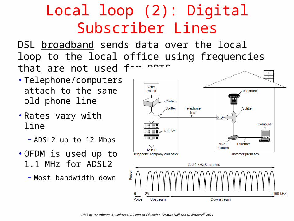
Local loop (2): Digital Subscriber Lines
DSL broadband sends data over the local loop to the local office using frequencies that are not used for POTS
• Telephone/computers attach to the same old phone line
• Rates vary with line
− ADSL2 up to 12 Mbps
• OFDM is used up to 1.1 MHz for ADSL2
− Most bandwidth down
CN5E by Tanenbaum & Wetherall, © Pearson Education-Prentice Hall and D. Wetherall, 2011
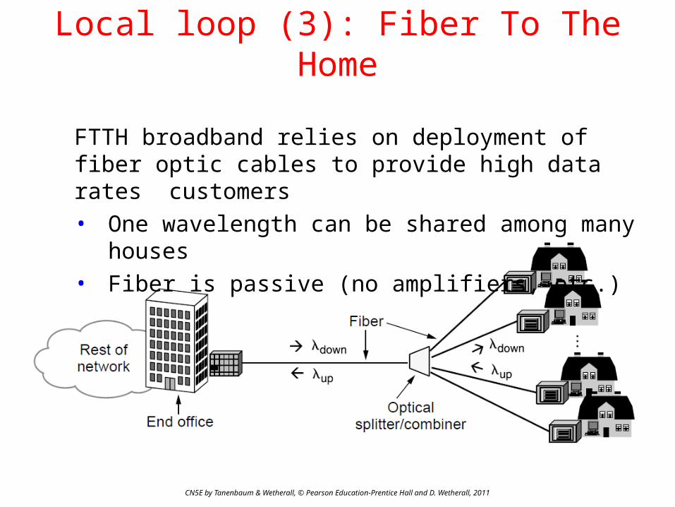
Local loop (3): Fiber To The Home
FTTH broadband relies on deployment of fiber optic cables to provide high data rates customers• One wavelength can be shared among many houses• Fiber is passive (no amplifiers, etc.)
CN5E by Tanenbaum & Wetherall, © Pearson Education-Prentice Hall and D. Wetherall, 2011
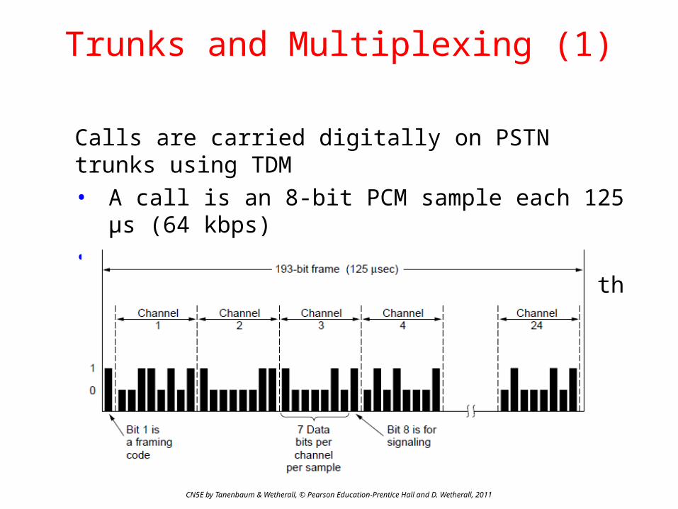
Trunks and Multiplexing (1)
Calls are carried digitally on PSTN trunks using TDM• A call is an 8-bit PCM sample each 125 μs (64 kbps)• Traditional T1 carrier has 24 call channels each 125
μs (1.544 Mbps) with symbols based on AMI

CN5E by Tanenbaum & Wetherall, © Pearson Education-Prentice Hall and D. Wetherall, 2011
Trunks and Multiplexing (2)
SONET (Synchronous Optical NETwork) is the worldwide standard for carrying digital signals on optical trunks• Keeps 125 μs frame; base frame is 810 bytes (52Mbps)• Payload “floats” within framing for flexibility

CN5E by Tanenbaum & Wetherall, © Pearson Education-Prentice Hall and D. Wetherall, 2011
Trunks and Multiplexing (3)
Hierarchy at 3:1 per level is used for higher rates• Each level also adds a small amount of framing• Rates from 50 Mbps (STS-1) to 40 Gbps (STS-768)
SONET/SDH rate hierarchy
CN5E by Tanenbaum & Wetherall, © Pearson Education-Prentice Hall and D. Wetherall, 2011
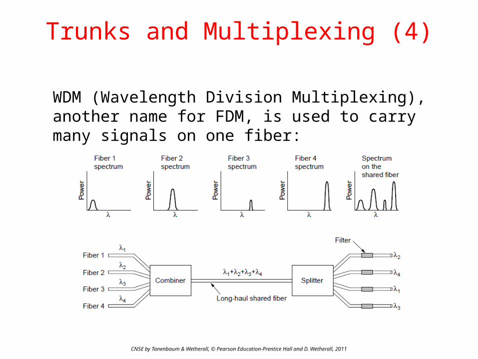
Trunks and Multiplexing (4)
WDM (Wavelength Division Multiplexing), another name for FDM, is used to carry many signals on one fiber:
CN5E by Tanenbaum & Wetherall, © Pearson Education-Prentice Hall and D. Wetherall, 2011
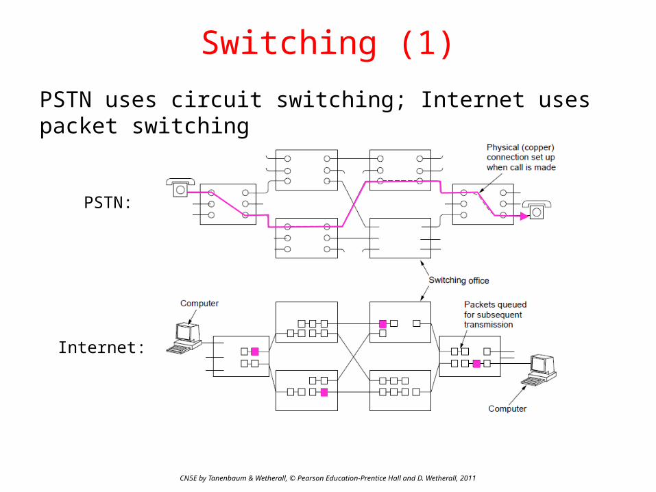
PSTN uses circuit switching; Internet uses packet switching
Switching (1)
PSTN:
Internet:

CN5E by Tanenbaum & Wetherall, © Pearson Education-Prentice Hall and D. Wetherall, 2011
Switching (2)
Circuit switching requires call setup (connection) before data flows smoothly• Also teardown at end
(not shown)
Packet switching treats messages independently• No setup, but variable
queuing delay at routers
Circuits Packets

CN5E by Tanenbaum & Wetherall, © Pearson Education-Prentice Hall and D. Wetherall, 2011
Switching (3)
Comparison of circuit- and packet-switched networks
CN5E by Tanenbaum & Wetherall, © Pearson Education-Prentice Hall and D. Wetherall, 2011
Mobile Telephone System
• Generations of mobile telephone systems »• Cellular mobile telephone systems »• GSM, a 2G system » • UMTS, a 3G system »
Generations of mobile telephone systems
CN5E by Tanenbaum & Wetherall, © Pearson Education-Prentice Hall and D. Wetherall, 2011
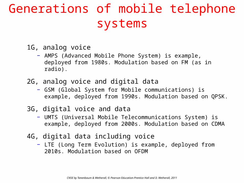
1G, analog voice− AMPS (Advanced Mobile Phone System) is example, deployed
from 1980s. Modulation based on FM (as in radio).
2G, analog voice and digital data− GSM (Global System for Mobile communications) is example,
deployed from 1990s. Modulation based on QPSK.
3G, digital voice and data− UMTS (Universal Mobile Telecommunications System) is
example, deployed from 2000s. Modulation based on CDMA
4G, digital data including voice− LTE (Long Term Evolution) is example, deployed from 2010s.
Modulation based on OFDM

CN5E by Tanenbaum & Wetherall, © Pearson Education-Prentice Hall and D. Wetherall, 2011
Cellular mobile phone systems
All based on notion of spatial regions called cells− Each mobile uses a frequency in a cell; moves cause handoff− Frequencies are reused across non-adjacent cells− To support more mobiles, smaller cells can be used
Cellular reuse pattern Smaller cells for dense mobiles

CN5E by Tanenbaum & Wetherall, © Pearson Education-Prentice Hall and D. Wetherall, 2011
GSM – Global System for Mobile Communications (1)
• Mobile is divided into handset and SIM card (Subscriber Identity Module) with credentials
• Mobiles tell their HLR (Home Location Register) their current whereabouts for incoming calls
• Cells keep track of visiting mobiles (in the Visitor LR)

CN5E by Tanenbaum & Wetherall, © Pearson Education-Prentice Hall and D. Wetherall, 2011
GSM – Global System for Mobile Communications (2)
Air interface is based on FDM channels of 200 KHz divided in an eight-slot TDM frame every 4.615 ms• Mobile is assigned up- and down-stream slots to use• Each slot is 148 bits long, gives rate of 27.4 kbps

CN5E by Tanenbaum & Wetherall, © Pearson Education-Prentice Hall and D. Wetherall, 2011
UMTS – Universal Mobile Telecommunications System (1)
Architecture is an evolution of GSM; terminology differs
Packets goes to/from the Internet via SGSN/GGSN
Internet

CN5E by Tanenbaum & Wetherall, © Pearson Education-Prentice Hall and D. Wetherall, 2011
UMTS – Universal Mobile Telecommunications System (2)
Air interface based on CDMA over 5 MHz channels• Rates over users <14.4 Mbps (HSPDA) per 5 MHz • CDMA allows frequency reuse over all cells• CDMA permits soft handoff (connected to both cells)
Softhandoff
CN5E by Tanenbaum & Wetherall, © Pearson Education-Prentice Hall and D. Wetherall, 2011
Cable Television
• Internet over cable »• Spectrum allocation »• Cable modems »• ADSL vs. cable »

CN5E by Tanenbaum & Wetherall, © Pearson Education-Prentice Hall and D. Wetherall, 2011
Internet over Cable
Internet over cable reuses the cable television plant• Data is sent on the shared cable tree from the head-
end, not on a dedicated line per subscriber (DSL)
ISP(Internet)

CN5E by Tanenbaum & Wetherall, © Pearson Education-Prentice Hall and D. Wetherall, 2011
Spectrum Allocation
Upstream and downstream data are allocated to frequency channels not used for TV channels:

CN5E by Tanenbaum & Wetherall, © Pearson Education-Prentice Hall and D. Wetherall, 2011
Cable Modems
Cable modems at customer premises implement the physical layer of the DOCSIS standard• QPSK/QAM is used in timeslots on frequencies that
are assigned for upstream/downstream data

CN5E by Tanenbaum & Wetherall, © Pearson Education-Prentice Hall and D. Wetherall, 2011
Cable vs. ADSL
Cable:+ Uses coaxial cable to customers (good bandwidth)− Data is broadcast to all customers (less secure)− Bandwidth is shared over customers so may vary
ADSL:+ Bandwidth is dedicated for each customer+ Point-to-point link does not broadcast data− Uses twisted pair to customers (lower bandwidth)
End
Chapter 2
CN5E by Tanenbaum & Wetherall, © Pearson Education-Prentice Hall and D. Wetherall, 2011