Embed Size (px)
Citation preview
The Planning and Building Instruments of Architects in the Late Middle Ages
Francesco Abbate
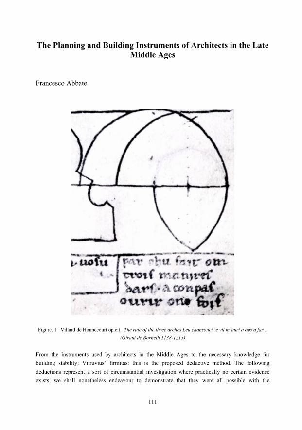
Figure. 1 Villard de Honnecourt op.cit. The rule of the three arches Leu chansonet’ e vil m’auri a obs a far...
(Giraut de Bornelh 1138-1215)
From the instruments used by architects in the Middle Ages to the necessary knowledge for building stability: Vitruvius’ firmitas: this is the proposed deductive method. The following deductions represent a sort of circumstantial investigation where practically no certain evidence exists, we shall nonetheless endeavour to demonstrate that they were all possible with the
111
knowledge of the time: this is not to say, of course, that such were their methods, however something quite similar was certainly employed. The architects of the time have hardly left any trace of their planning and building methods, almost as if to preserve the secrets of their workshops, limiting to the bare minimum their revelations: only what was absolutely essential to actually carry out the building came out of their chamber des traits (drawing studio), nothing whatsoever concerning the design procedures. There exist few exceptions with some sort of evidence and among them there is the drawing of the rose window of the cathedral of Chartres, transferred by Villard de Honnecourt, not as it was successively built, but during a planning phase, which leads us to presume that he was in some way linked to the architects who were actually working on it. The development of building techniques in the architecture of the late Middle Ages, which is considerably different from that of the previous centuries, seems to be the result of a natural evolution of building techniques rather than a continuous search for improvements to apply to better and more logical workmanship. Even if in a cryptic manner, this is visible in Villar de Honnecourt’s Livre de Portraiture which could be considered the builder’s manual of the time, an avant-garde handbook for the building and perhaps even the work optimization solutions it contains. Among the evidence present in the architecture of the time, the drawing (folio 21 recto) (fig. 1), known as the rule of the three arches, is particularly significant. “Par chu fait om trois manieres d’ars a compas ovrir one fois”, by opening a pair of compasses only once three types of arches can be inscribed: a round arch, a quarter lancet arch and a pointed arch that have the same radius in common and all that derives from a constant radius; centring curvature, ashlaring, but above all the organisation of the building yard and the different ways of assembling equal elements. What has so far been examined now needs to be confirmed through application: let’s apply it to a church viewed through the schematic development of the typology. In cathedrals where the technology of the vault structure was employed (with reference to the rather simple pattern of an aisleless church with side chapels), cross vaults on a square plan were built for the nave and cross vaults half of the width on a square plan for the chapel, so that two chapels on each side corresponded to the nave vault. The medieval cross vaults generally have diagonal round arches and the side arches are pointed, obviously raised to obtain the alignment of the keystones (fig 2 A); this solution, however, does not allow the contrasting inward thrust generated by the transversal and diagonal arches of the chapels that are in the centre of the nave arch: the solution to this problem was obtained only by increasing the load on the separating walls of the chapels, impeding a solution with pillars. In order to rest the vaults of the chapels and the nave on pillars, at least a planimetrical contrast of the thrusts is necessary by inserting in the vault a transversal arch (arc doubleau) half way along the nave vault
112

to obtain a six-part cross vault (fig. 2 B) such as in Notre-Dame-de-Paris and in the nave of the cathedral of Laon where, however, the transept has a different solution. These vaults have three different arches: the round diagonal arch, the pointed arches, the quasi-quarter lancet arches, in direction of the nave, and the quasi-ogives towards the chapels, but, even if the components are optimised, a six-part cross vault is rather complicated to build because the elements are too diversified. The simplest solution indicated by Villard de Honnecourt in the rule of the three arches results in a quadripartite vault with round diagonal arches, quarter lancet arches towards the nave and ogives corresponding to the chapels: this is the solution Villard de Honnecourt adopted in the apse of the cathedral of Meaux which he apparently planned.
Figure 2 Development Of The Medieval Cross Vault: A quadripartite cross vault on square plan B six-part cross vault
C quadripartite cross vaults on rectangular plan D from Auguste Choisy, op. Cit. The geometry of vaults From the geometrical comparison of the rule of the three arches, it can be immediately deduced, however, that the contemporary assembly in a rectangular cross vault of the three arches, round,
113

quarter lancet and ogive, as described in Villard de Honnecourt’s drawing, is not possible. It seems hardly fit to disregard the unification of the ashlaring and the shaping of the centring. Given, therefore, the single radius, the planner has other adjustment elements at his disposal: compensate by modifying, even slightly, the span of the pointed arches (by means of a cusp. i.e. the insertion of non-tapered ashlars in the keystone) and vary the thickness of the poly-stile pillars, or both at the same time. Furthermore, to obtain the alignment of the keystones of different arches, the springer level was adequately varied. The quadripartite cross vault solution on a rectangular plan (fig. 2 C) in fact replaced the six-part vaults and it is present in all the successive cathedrals: Chartres, Reims, etc., right up to the cathedral of Amiens.
Figure 3 HUGUES LIBERGIER’S COMPASS: A The compass (detail of the gravestone) B The reconstructed compass C The spread of the compass-legs according to the rules of the three arches D Hugues Libergier’s gravestone
In 1264, the abbot of Saint-Nicase, Hugue Libergier, died in Reims. He seems to be the author, or co-author with Robert de Coucy, of the plans of the cathedral of Reims, where his gravestone is placed (fig. 3 E). On the stone, to signify his activity as architect, are engraved a square and measuring rod as well as a mysterious pair of compasses which looks more like an instrument
114

similar to an alterable pattern that in three of the possible positions not only fits in perfectly with Villard de Honnecourt’s rule of the three arches but also completes it, enabling to draw an infinity of arches (allowing the automatic adjustment of the pattern) implied in the very principle of a common radius (fig. 3 A). This interpretation seems rather narrow and hardly justifies the construction of an instrument that compared to an ordinary pair of compasses could draw the same things with the limitations of the compulsory radius of the pattern (fig. 3 C). We know that in building arches and vault structures it was then quite a common practice, just as it is today for the few remaining master vault builders, to add appropriate counterweight, even if empirically, to the arches and the vault span during construction (fig. 3 D). This is absolutely essential in a construction without centring or reduced centring, since the structure behaves as such from the very start and the least imbalance could have catastrophic consequences. The thickness difference of the so-called Libergier’s compass, as deduced directly from the representation engraved on the gravestone, logically assuming that its author placed the original directly on the drawing, could well indicate the necessary counterweight for the arch being constructed, when it’s a round arch, given the necessity to place specific weights on the keystone, when the geometry of the curve showed interruption as in the case of a pointed arch.
Figure. 4 ROPE BALANCING : A Rope balancing model of a round arch B Rope model of the cathedral of Reims C Weight distribution in the cathedral of Barletta D Rope reconstruction of San Lorenzo in Naples E Frontispiece of Stevin’s Hipomnemata Mathematica All this tends to indicate that in the 13th century there existed the necessary technical and mathematical means to determine the correct load an arch should bear, how was it otherwise possible to achieve such admirably balanced structures? Some sort of method surely existed: trial and error, as some suggest, would have been extremely dangerous and many more than have
115

actually been documented would have collapsed. (Imagine the number of victims caused by the dismantling of the cupola scaffolding of Santa Maria del Fiore in Florence if Brunelleschi had not managed to find the correct balance during the various stages, building it without centrings and if these had really been constructed in packed earth mixed with gold coins, as suggested by Vasari’s imagination). Of course a method is not written down until Simon Stevin’s Hypomnemata Mathematica in 1608 that “Wonder en is gheen Wonder” (astonishment is no longer an astonishment) (fig. 4 E). Stevin, however, never claims to have discovered a method to calculate the balance of the arches, he simply systematizes it; besides, the term Merveille (Astonishment) was in use since 1212 to indicate a complex of buildings in Mont-Saint-Michel constructed by Raoul des Iles; it’s reasonable to assume that Stevin was referring to the astonishing balance of late medieval constructions. In the Middle Ages, it was certainly possible to build a model of an arch with strings and it was sufficient to draw it upside down on a flat surface, with two nails to mark thirty degrees (the limit position of the arch was already well-known) and tie a string of the same length as the inscribed arch. Variable weights (such as sandbags) could be hung on the string and the load patiently changed until it coincided with the described arch. This exact but rather laborious method could be replaced by a more logical and immediate system: a multiple scales machine with sliding rods enabled to gauge the exact distribution on the string, starting from a sole counterweight, until it coincided with the described arch. Obviously, this method of analysis, giving always the same result, was codified once and for all and applied to an instrument (Libergier’s compass) in which the internal curve follows the described arch and the external curve traces the necessary load of the counterweight. With the reconstructed compass it’s possible to verify that, having described and then disassembled the round arch, it’s sufficient to match the internal curve of one of the two parts overturned with the drawing of the difference of the curves to obtain the drawing of the counterweight (fig 3 D). However, in the case of a pointed arch, a keystone load was necessary to stabilise it and, in fact, a mullion window with two lights was set above a window with one light, one with three lights above one with two. As for vaults, various solutions can be noticed, such as the roof covering of the cathedral of Meaux, constructed to alternate the keystone load on the pointed arches to unburden the diagonal round arch keystone. Having reconstructed the probable scales system to define the ideal load performance on a round arch, an immediate invariant solution emerged that did not justify its use; the load performance
116

could be codified and thus Libergier’s pattern-compass interpretation becomes plausible. If, however, this scales system can equilibrate an arch in relation to the ashlar barycentre, then it can be extended to more complex structures, as long as they pertain to plane situations, and all late medieval constructions can be ascribed to the plane (fig. 4 A). Lacking any documented knowledge of specific methods used by medieval builders, we have endeavoured to carry out plausible experiments on some significant examples of structures where the stability has been ensured by different methods: the cathedral of Reims, Santa Maria Maggiore in Barletta (Apulia) and San Lorenzo in Naples. The choice of these three buildings was based on the different typologies and systems of equilibrium of the thrust: flying buttresses in the case of Reims, whose apse section is reported by Villard de Honnecourt, limestone covering as counterweight in Santa Maria Maggiore in Barletta and walled arches in San Lorenzo in Naples (fig. 4 C). These are not the only examples worthy of study: every building could be considered on its own, but lack of space perforce obliges to concentrate on three that, in our opinion, are amongst the most famous and significant as far as the approach to the problem of plane equilibrium is concerned. As already mentioned, in the cathedral of Reims, typical of cathedrals in the Ile de France region, the thrust of the entire vault system is balanced by a system of flying buttresses pushing towards the counterforts, which is also what takes place in the apse of the church of San Lorenzo in Naples, aptly considered the most French of the medieval churches of the city. The nave of San Lorenzo is instead different from the French model imported by the Anjou kings: it has a trussed roof – typical of the churches of Naples of the time – which induces to think that another solution became necessary due to contingencies that modified the model. The theory sustained by some concerning the diversity of materials doesn’t seem convincing since the tuff of Campania (Pozzuoli tuff, to be precise) was efficaciously employed for the apse where the radial thrust is conveyed towards the buttresses according to the imported model; instead there seems to be validity in the hypothesis of the necessity to create disjointedness in the structure, and the trussed roof does just that, to resist better to a phenomenon unknown in Ile de France: earthquakes, which had already obliged the architects building the Maschio Angioino (the Angevin Keep) to replace a planned vault with a wooden covering. If ropes or strings, on the one hand, may have been used to define a planning method of medieval buildings, although there is no documented evidence that has reached us and it has therefore been necessary to assume a probable application, on the other, it appears indispensable in drawing the construction and proof of this, fanciful though it may seem, does indeed exist: it concerns the builder of the third abbey of Cluny. The legend narrates that saint Peter, saint Paul and saint Stephen appeared in dream to the architect Gauzon, drawing on the ground the plan of the abbey with the aid of ropes. Why bother three saints
117

for a drawing? Because three people are needed to determine a right angle using the so-called Druids’ rope, a rope with twelve knots at thirteen equal intervals. With this rope (fig. 5 A,B,C e D) it’s possible to construct a right-angled triangle with the exact Pythagorean triple 3-4-5 and therefore the right angle as well as an acute angle of 36°52’12” and one of 53°7’48” at the vertex. But even with three saints pulling taut the Druids’ rope at the vertices to form one of the possible triangles, it’s not possible to draw it on the ground: the triangle has to be horizontal and a suitable instrument is needed, the plumb rule, known since ancient times and reported in many representations of the time. In particular, that of the stained glass window of the cathedral of Chartres, properly reconstructed, has shown a precision worthy of the spirit level. The faithful reconstruction of the plumb rule of Chartres, with the eccentric position of the handle, has revealed how important the handiness of the instrument was at the time: the handgrip allows the wrist to coincide with the centre of rotation, thus eliminating all superfluous effort adding precision to the horizon adjustment (fig. 5 E).
Figure 5 The DRUID’S ROPE and the PLUMB RULE: A Rectangular triangle from the Pythagorean triple 3,4,5 B Isosceles triangle from the triple 5,4,4 C Isosceles triangle from the triple 5,3,3 D Isosceles triangle from the triple 4,4,4 E The Chartres plumb rule (reconstruction) F Representation of the plumb rule on a stained glass window of Chartres
118

Regarding tracing on the ground, the triangulation and sighting systems, as they are represented in Villard de Honnecourt’s Livre de Portraiture, were well-known. On Hugues Libergier’s tombstone, there is a representation of the measuring stick, la canne des Maîtres d’oeuvre, summarising the measuring systems in use at the time clearly deriving from applications of the golden section. The measuring system of the time began from the smallest measure of the line (ligne) taken from the diameter of a grain of barley – the smallest basic measure – and was traditionally represented in inches, feet and arm spans, where an inch was the equivalent of 12 lines, a foot equalled 12 inches and an arm span was 6 feet: a sexagesimal sequence, therefore, which permitted exact subdivisions. Furthermore, a clearly anthropometric (fig. 6) subdivision applied to the metric rod was in use: a hand span (paume), palm (palme), handbreadth (empan), foot (pied) and cubit (coudée), always in relation to entire parts of the basic line. The corresponding value in relation to a metre is inferred from the following table deduced from the table reported in Cahiers de Boscodom, number 4: Henri Bilheust, L’art des bâtisseurs romans, 1990.
Figure 6 ANTHROPOMETRIC MEASUREMENTS
It’s worthy to note that the sequence hand span, palm, handbreadth, foot and cubit is expressed according Fibonacci’s progression so that a hand span + a palm = a handbreadth, a palm + a handbreadth = a foot and a foot + a handbreadth = a cubit and this is true both for Chatelet’s sample and the insider sample which differ slightly in the basic diameter measure of the barley grain (Chatelet’s sample is cm. 0,22558 while the insider sample is cm. 0,2247). The master
119

builders’ measuring stick employed the insider measure which was 555 lines long (m. 124,7085) and was divided in hand span, palm, handbreadth, foot and cubit and was just over two lines shorter than Chatelet’s sample. If the terms inch, foot, cubit and arm span recall the classic Attic-Roman measures, others have disappeared, such as digit and of the sequence 1hand span=4 digits and 1 hand span=3 inches, 1 foot=4 hand spans and 1 foot=12 inches, 1 cubit=6 hand spans and 1 cubit =18 inches, 1 arm span=4 cubits and 1 arm span=6 feet there only remains the division of the foot in 12 inches and the arm span in 6 feet. Two measures of anthropometric origin were added to the hand span, the palm and the handbreadth, more suitable for progressive measurements in order to reduce the margin of error implicit in measuring objects by sum. Fibonacci’s succession, close to the golden ratio1.618033989, has permitted to obtain through the sum what was previously possible only by geometrical construction with ruler and compass: the possibility to draw directly without recurring to a system of projection and sight, simplifying the use of the plane-table and sighting technique. There is synthetic evidence of the plotting and drawing methods in Villard de Honnecourt’s Livre de la Portraiture, folio 20 recto and verso (fig. 7), methods always obtained by means of similar triangles and by sighting an inaccessible point, and which are also found in the use of the plane-table well-known since Roman times. On Hugues Libergier’s tombstone is also engraved a peculiar square: from the dimension ratio with the measuring stick which is engraved as well, it’s possible to deduce the dimension of the greater arm equal to a cubit (cm 52.36). The interesting thing about this square is that the outer and the inner borders, though subtending a right angle, are not parallel in analogy with the square represented several times by Villard de Honnecourt (folio 20, recto and verso). Villard de Honnecourt describes the use of the square to cut the vault toothing (fig. 8 A), to draw non-right angles (fig. 8 B), for circles double the area (fig, 8 C) of another and to obtain the diameter of circular objects (fig. 8 D). The angle formed by the outer and inner borders of the arms of the square present in Villard de Honnecourt’s examples is clearly different from the angle engraved on Hugues Libergier’s tombstone, which leads us to think that several such squares were in use and the angle was different according to the required use, though the functions remained unvaried. In folio 21 recto, Villard de Honnecourt gives a description of the drawing method, referred to an outer and inner right angle of the square, by rotating a previously fixed angle. Although Villard de Honnecourt has not left us any detailed description and Hugues Libergier took his secrets with him on his grave, the most logical function of this square is given by the angle formed by its external and internal parts, the angle that represents the tapering of the ashlars of the arches and the vaults. This would imply different squares for different arches but the already quoted trend towards the unification of the radius in the construction of rectangular cross vaults leads to the
120

unified use of the same square with the due adjustments. Among the examples of this application there is the nave of the cathedral of Meaux in which the quadripartite rectangular cross vaults were accomplished by a lateral ogive, diagonal round arches and the adjustment of the transversal arch was obtained by the spiral of ten parallel-plane ashlars in key to maintain the curve radius equal to the other arches and hence the same edge of the ashlars using, of course, the same square (fig.9).
Figure. 7 Villard de Honnecourt, op. cit folio 20 recto and verso
Figure 8 from Villard de Honnecourt, Figure 9 THE POINTED ARCHES op. cit., USING the SQUARE of the CATHEDRAL of MEAUX
121

The same radius and the same ashlars also involve the same centring and it’s logical to suppose the application of the telescopic centring rediscovered and reused by Eugene Viollet-le-Duc in many restoration works (fig.10). The necessity to maintain the radius as constant as possible for arches with different spans led to the birth of the entire vault system in medieval architecture. The continuum of traditional vaults or of Roman derivation was abandoned for a system of assembling structurally different elements with a precise hierarchical function in the structure as a whole. It’s here necessary to make an assumption about the development of the cross vaults, starting from the cross vault of the Romans. This vault, usually achieved with a concretion moulding, obviously needed a complete and rather sturdy mould to hold the weight and even though the opus cementicium was made of the lightest inert material available (lapillus), this provisional work had to carry out its function for a long time until the lime concrete set. And even the certain advantage of achieving an almost monolithic structure, thanks to this technique, was in any case undermined by the considerable pressure that these vaults exerted on the rest of the structure. It must not be forgotten that the Roman cross vault is generated by the intersection of two round barrel vaults with equal radius, the four groins that form it have the advantage of a fluted surface and therefore its mould can be made with flat boards, the diagonal arch, however, is an ellipse and it’s precisely the diagonal thrust that compelled the builders to contrast these vaults with other quite massive structures. If this, for the Romans, did not entail great problems, since they supported their structures with a wall continuum, when building techniques started to move away from the continuum to single elements, the reduction and the control of the thrust of a structure became extremely important for builders. In order to reduce the thrust, the diagonal arch had to be round too. However, keeping the lateral arches round, the groin surface was no longer fluted and would have involved a specific formwork which would have complicated quite a lot the construction and would have also augmented the transversal pressure on the side arches; furthermore, with this type of arches, the radius singleness is lost. If, instead, the radius remained constant, the automatic result is an acute arch whose rise is however inferior to that of the diagonal arch: in order to keep the vault groins cylindrical an artifice was needed, raise slightly the springer of the lancet side arch to bring the key to the same level. Referred to the unitary radius, the rise is 0.9561 and the inscribed base angle of the isosceles triangle is 53°30’8”, very close to the angle of 53°7’48”, the greater of the two acute angles obtained by the Druids’ rope with the exact Pythagorean triple 3-4-5. For the reasons that have so far been analysed, this type of cross vault on a square plan was replaced by the six-part cross vault on a plan close to a square with a ratio varying from 9:10 of Notre-Dame-
122

de-Paris to 7:10 of the nave of the cathedral of Laon. Even in the case of six-part cross vaults, it becomes necessary to adjust the keys of the arches or raise the lancet arch springers.
FIGURE 10 MEDIEVAL CENTRINGS A from E. Viollet Le Duc, op. cit., Telescopic centring B from A. Choisy, op. cit, Centring techniques C from J. Fitchen, op. cit., scaffolding systems of Gothic vaults The use of the ogive for the side arches was always preferred and hence raise the springer, whilst for the transversal arches of the naves, also due to an inferior height, other techniques such as the cusp were used. Besides, the overall visual impact was not in the least affected, also because these structures were destined for further decoration, since the main task of architects has always been to hide from sight the discrepancy of forms or, as we say in Naples, cummuglià ’e schifezze (hide the rubbish under the carpet). Inspired by Villard de Honnecourt’s rule of the three arches, the development of the cross vault turned back to the quadripartite but on a rectangular plan, bringing a pair of vaults close to the planimetrical square. This system does indeed need another transversal arch, but the uniformity of the vault spans made it so much easier to construct that it was adopted in the transept of the cathedral of Laon and in all the cathedrals that followed. In the side aisles, the layout of the cross vault on a square plan was maintained by utilising the ogives of the nave for the side arches and
123
consequently the radius of the transversal round arches had to be varied. These structures are particularly fascinating because of the perfect visual equilibrium of the forces that were put together to create them. Most of them have outlasted time, layer upon layer, almost out of a sense of horror vacui, deprived of all the frills that have sometimes concealed them. Fortunately, plaster and painting have not lasted and it’s thus possible to gaze upon the structure almost as it was originally conceived. It’s a type of structure accomplished by means of elementary but efficient instruments thanks to a constant search for simple techniques acting in unison. Based more on testing rather than planning, the construction theory, which has developed in the present form during the following centuries, has replaced structural intuition, typical of the master architects of the Middle Ages, but it will never be able to take the place of all the knowledge that can be defined as the art of building. These medieval structures are evidence of the long-neglected intuitive structure calculus know-how which however remains so ingrained in human thought that it continuously crops up from time to time in masterpieces of architecture.
SPECIAL THANKS
I am grateful for the cooperation in reconstructing the models to the architects Daniela Galasso (cathedral of Reims), Ulderica Lucera (Santa Maria Maggiore in Barletta), Margherita Risolo (San Lorenzo in Naples) and Salvatore Lovecchio (Libergier’s compass). My heartfelt appreciation to architect Maria Lippiello who should have been co-author of this research. REFERENCES Abbate, F, 2005. Sollecitazione e forma – la forma delle strutture, Naples. Catelnuovo, E and Sergi, G, 2003. Del costruire: tecniche, artisti, artigiani, committenti in Arti e storia nel Medioevo, vol. II, Venice, 2003 Choisy, Auguste, 1867. Histoire de l’achitecture, Paris. Coldagelli, E, 1968. Gothic in Dizionario Enciclopedico di Architettura e Urbanistica, Rome. De Honnecourt, Villiard, 12th century manuscript. Livre de Portraiture. Fitchen, John, 1961.The Construction of Gothic Cathedrals, A Study of Medieval Vault Erection, Oxford.
124

Galasso, D, 1994. Villard de Honnecourt e la “Rivoluzione strutturale del Medioevo”, Naples. Gimpel, J, 1980. Les bâtisseur de cathedrales, Paris, 1980 Oudin, B, 1994. Dictionnaire des Architectes, Paris, 1994 Viollet Le Duc, Eugene, 1854-1866. Dictionnaire raisonné de l’architecture française du XI au XVI siècle, Paris.
125


![LIST OF REGISTERED ARCHITECTS 2000 - slp.wa.gov.au · PDF file3 February 2000] GOVERNMENT GAZETTE, WA 395 ARCHITECTS ACT 1922 REGISTER OF ARCHITECTS Architects Board Of Western Australia](https://img.pdfslide.net/doc/110x75/5a7e2eae7f8b9a66798e41b5/list-of-registered-architects-2000-slpwagovau-february-2000-government-gazette.jpg)