Embed Size (px)
Citation preview
REPORT OF GEOT~CHNICAL EXPLORATION
THE PONDS Alr LAFAYETTE (LAFAYETTE BUS,NESS PARK - PARCEL 2) Fairf.. Counly, VirgiDi~
APRIL 2005
Prepared For:
MOORE & ASSOCIAliES, INC. 8484 Georgia Avenue. S~ite 720 Silver Spring, Maryland 20910
Attn: Mr. Jeffery M. Grijfin
Prepared By:
GEO-TECHNOLOG~SSOCIATES'INC. Geotechnical and Enviro menial Consultants 45064-A Underwood L Sterling, Virginia 20166, (703) 478-0055
GTA Job No: 041370
I (~;" ~
April 27, 2005
Moore & Associates, Inc. 8484 Georgia Avenue, Suite 720 Silver Spring, Maryland 20910
Attn: Mr. Jeffel)' M. Griffin
Re: Report of Geotechnical E~ploration (Revised) The Ponds at Lafayette (fa/ayelte Business Park - Parcell) Fairfax COWlty, Virginia,
Gentlemen:
In aceordance with yourl request" Geo-Teclmology Associates, Ineorporated (OTA) has completed a geotechnical expl0tfltion for the above refereneed project. Transmitted herein is a revised report of our findings *,d conclusions regarding foundation support, slab support, site grading, pavement subgrade pre aration, and utility eonstruction. The work was completed in accordance with GTA's proposa dated December 3, 2004.
I
Thank you for the opporpunty to be of assistance on this project. Should you have any questions or require additional i~formation, please do not hesitate to eontact our office.
!
Vel}' truly yours, GEO-TECHNOLOGY ASSOCIATES, INC.
filJ' Naseer Nayeem, P.E. ,,::Eo. Proj t Engineer
Am an, P.E.
, Viee President ,
Cc: Mr. David Dwomik, RinkerlDesign Associates
NN(L:\Docs\Report\2004\041370_Lafayetle BusfneSYl Plllk\lAf:tyetle Buisness Part Geok:ch Report'rev,doc) ].0. #041J70,V ,
I, ,- -,.
,- ,-"

TABLE OF CONTENTS
---------1 PAGE INTRODUCTION 11
SITE CONDITIONS I 1
PROPOSED CONSTRUCTIONI · 2 1
SITE GEOLOGY I .3
SUBSURFACE EXPLORATI01 5
SUBSURFACE CONDITIONS .1 6
LABORATORY TESTING 1 7
CONCLUSIONS AND RECO~NDATIONS 8
Earthwork 9i Subsurlacc Utilities -f 11 Foundations , ~ , 12 Seismic Infonnation 131 ,
Floor Slabs 141
Retaining Wall I 14 Pavements : 16
ADDITIONAL SERVICES I 1 17 ,
~:~A:::~;.~~=~~~~.J~~~;.;~~.~~~~:~~l~~~~~~=~..~~~~ 17 APPENDICES
Appendix A - Figures ,: Figure No.1 -ISite Location Plan Figure No. 2 -~'Site Soils Map Figurc No, 3 - Boring Location Plan Figure Nos. 4 ugh 9 - Subswface Profiles
Appendix B - Soil Boring Lo~s Notes for Borijtg Logs (1 Sbeet) Soil Boring Lqgs (33 Sheets)
Appendix C - Laboratory Daja (6 Sheets) I
1
1
REPORT F GEOTECHNICAL EXPLORATION
T PONDS AT LAFAYETTE F IRFAX COUNTY, VIRGINIA
I APRIL 2005
I
INTRODUCTION
Moore & Associates, In . plans to eonstruet two office buildings within the Lafayette
Business Park in the Chantilly ar a ofFairfax County, Virginia. The larger flex-industrial building
(Building # 1) with mezzanine 0 ce level will be located on the northern portion ofthe site and a 2
story office building (Building # ) will be located on the southwestern portion of the site.
In conjunction with the proposed improvements, Geo-Technology Associates, Inc. (OTA)
was retained to perfonn a geotec~ical exploration of the site. The scope of this study ineluded a
field exploration, laboratory testi~g. and engineering analysis. lncluded in the field exploration were
33 Standard Penetration Test bo~gs located within the proposed building, utility and pavement
areas of the site. Limited labor~tory testing was performed upon samples recovered during the
subsurface exploration. A site p an named The Ponds at Lafayette dated April 2005, prepared by
Rinker Design Associates, P .C. A) was reviewed by GTA. Conclusions and recommendations
regarding site development were erived from engineering analysis offield and laboratory data and
review of the site plan. I ,
A Phase I EnvironmentallASSessment entitled Lafayette Business Center - Parcel 2, dated
January 24, 2005, was previousl~ prepared by GTA and has been presented under a separate cover.
I SITE CONDITIONS I
The property is located at e southwestern comer ofthe intersection ofPleasant Valley Road
and Lafayette Business Drive, wi 'n the Lafayette Business Park in Chantilly, Virginia. The site is
bounded by Lafayette Business rive to the north and east, Pleasant Valley Road to the south, and
commercial properties to the we t. A site location map is included as Figure 1 in Appendix A.
Report of Geotechnical Exploration' Tht Ponds 111 Lafaytttt A ril2005 GTA Pro eetNo. 041370
, The site is mostly covered rth shrubs and brushes with occasional trees at the central JXlrtion
of the site. The RnA site plan sh4ws an existing stonnwater management (SWM) pond located at
the northeastern comer of the sitel and encompasses approximately 2 acres.
!
I The subject property slopef gently downward to the east toward the SWM JXlnd. Aneasterly
trending drainage ehannelloca~1Dear the central portion of the subject property conveys surficial
drainage from the northern, south rn, and western JXlrtions of the subject property toward the SWM
pond. The site plan indicates that e maximwn surface grades approach elevation 274± feet above
Mean Sea Level (MSL) on the so~em portion of the site. Minimum surface grades approach 262±
feet above MSL on the northernl~entral portion of the site.
I
Review of the Fairfax Cqunty Soils Map for the site and previous environmental studies
perfonned at the site indicates th~t a portion of an old farm pond existed at the site in the 1980s in
the western portion of the propertt. The environmental reports indicated that the pond was filled in
without removing the topsoil lay, and a portion ofLafayette Business Drive was constructed over
the pond. The extents and orig~al elevations of the bottom of the filled-in pond within the site
bOWldaries are Wlkno'W£l at this ti~e.
PROPOSED CONSTRUCTIO~ I
Based on the previously rEerenced site plan, the proposed improvements will consist oftwo
office buildings. The larger U-s ped building will be approximately 76,695 square feet (sf) with
approximately 20,000 sfofmezz . e level. In addition, a 2-story office level will be constructed at
the northeastern comer ofthe bui¥mg. The building will be 1] 7 feet wide. The larger building \-ViD
be located in the northern portioh of the site and \-Vill be an integrated single-story flex-industrial
warehouse \-Vith a dock and van Ida-ding area. The smaller building to be Located in the southwestern I
portion of the site \-ViII be a 2-stcfry L-shaped building and will be approximately 31,100 sf. The
Finished Floor (FF) elevations for the buildings are planned at El. 266.5 feet above MSL for
Building #1 and El. 265.5 feet ~bove MSL for Building #2. A retaining wall is planned on the
western side of Building #2. Th~ maximum exposed height of the retaining wall \-ViII be 4 feet.
2

Report ofGeokchnkal Exploratio The Ponds at Lafayene A ,iJ 2005 GTA Pro'ectNo. 041370
The site plan indicates that the office buildings will be surrounded by parking facilities, and
accessed by proposed entrances lqcated along Pleasant Valley Road and Lafayette Center Drive. In
addition, the existing triple RCP tor stonn sewer will be rerouted to follow the property boundary ,
behind the larger building and thqn discharge into the existing SWM pond.
SITE GEOLOGY
According to the Geolo&J/r Map of Virginia_(1993), the site is located within the Jurassic
Triassic Mesozoic Basin, which p~allels the western edge ofthc Piedmont Physiographic Province.
The basin is comprised of the D+ville, Scottsville, Burnley, Barboursville, and Culpeper Basins,
which have been categorized as Ibelonging to the Newark Supergroup, The subject property is
underlain by the undifferentiat~d sandstone portion of the Newark Supergroup, which is
characterized by light-gray to red~rown, interbedded sandstone, siltstone and shale which has been ,
intruded by diabase. Diabase is ai extrusive igneous rock, which occurs as dikcs and sills intruding
the parent materiaL. These rocks! are generally more resistant to weathering than thc sedimentary ,
rocks and commonly decomposel to fme sand and silt mixturcs, with significant clay fractions in !
some regions. Based on the com~ination ofsedimentary and igneous rocks, differential weathering I
is common and as a result, the Ne1v"ark Supergroup is characterized by irregular rock profiles. These
rocks weather into a saprolite ot variable thickness, underlain by less weathered and relatively
competent bedrock,
;
More specifically, the ncif-surface soils at the sitc typically consist of sand and silt, mixcd
with clay and trace to some roc~ fragments weathered from the bedrock. For a more detailed
description of the geologic unit, flease refer to the above publication.
, According to the Soil sutvey ofFairfax County, Virginia, published by thc United States
Department of Agriculture, soillConservation Service in cooperation with Virginia Polytechnic
Institute and State University, ~e subject site is underlain by 4 soil types. Bucks Silt loam, ,
Undulating Phase (71B2) is [oc+-ted on the northwest comer of the site, Readington Silt Loam,
Undulating Phase (273B 1) is 10cJted on the southern one-third portion ofthe property and in a smali
3
Report ofGeotechnical Exploratio The Ponds at LafayetJe A rUlOOS GTA Pro ectNo. 041370
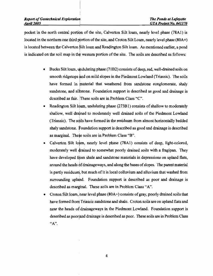
pocket in the north central porti<)n of the site, Calverton Silt loam, nearly level phase (7RAI) is
located in the northern one third pbrtion of the site, and Croton Silt Loam, nearly level phase (80A+) ,
is located between the Calverton ~ilt loam and Readington Silt loam. As mentioned earlier, a pond
is indicated on the soil map in tht western portion of the site. The soils are described as follows:
• Bucks Silt loam, urdulating phase (71B2) consists ofdeep, red, well-<lrained soils on
smooth ridgetops and on mild slopes in the Piedmont Lowland (Triassic). The soils , ,
have formed in Imaterial that weathered from sandstone eonglomerate, shaly
sandstone, and silbtone. Foundation support is described as good and drainage is
described as fair. :These soils are in Problem Class "C".
• Readington Silt IQam, undulating phase (273B1) consists ofshallow to moderately
shallow, well dratned to moderately well drained soils of the Piedmont Lowland ,
(Triassic). The sqils have formed in the residuwn from almost horizontally bedded
shaly sandstone. foundation support is described as good and drainage is described
as marginal. The~e soils are in Problem Class "B".
• Calverton Silt lorm, nearly level phase (7RAI) consists of deep, light-colored,
moderately well (,trained to somewhat poorly drained soils with a fragipan. They
have developed filom shale and sandstone materials in depressions on upland flats,
around the heads <Dfdrainageways, and along the bases ofslopes. The parent material
is partly residuwq, but much of it is local colluviwn and alluvium that washed from ;
surrounding upla,b.d. Foundation support is described as poor and drainage is
described as mar~l. These soils are in Problem Class "A".
• Croton Silt loam, :near level phase (80A+) consists ofgray, poorly drained soils that
have formed fro~ Triassie sandstone and shale. Croton soils are on upland flats and
near the heads ott drainageways in the Piedmont Lowland. Foundation support is
deseribed as poor land drainage is deseribed as poor. These soils are in Problem Class
"A".
4

Report ofGeotechnical Exploration., The Ponds at Lafayette Apri1200j , GTA Projec:tNo. 04IJ70
The Fairfax COWlty Soils. Map, which depicts the distribution of the soil types within the
vicinity ofthe site and approximate extents of the old pond, is included as Figure 2, in Appendix A.
SUBSURFACE EXPLORATlql!
In order to characterize the general subsurface conditions at the site, 33 borings, designated
B-1 through B-21, P-l through P,?, and 8-1 through 8-5 were drilled at the proposed improvement
areas at the site. The locations flj'lr the test borings were seleeted and field located by GTA using
existing site features and hand ~ld GPS (Garmin 60C) as shown on the Boring Location Plan,
presented as Figure 3 in Appendi~A. GroWld surface eJevations were not provided. However, GTA
has estimated the ground surface ¢Ievations at the boring loeations from the site plan. Therefore, the
boring locations and elevations s.ltould be considered approximate. The Boring Location Plan is a
reproduction of the site plan prepared by RDA, altered to show the boring locations.
Borings B-1 through B-15 were drilled in Building #1, Borings B-16 through B-21 were
drilled adjacent and within the 2-,tory building (Building #2), Borings P-I through P-7 were drilled
in the paved areas, and Boring S-l through S-5 were drilled along the new alignment for the
relocated triple RCP. The larger building (Building #1) area borings were planned to be drilled to
depths of 15 feet below existing :;Inface grades or to refusal, the 2-story building (Building #2) area
borings were planned to be drilled to 20 feet below existing surface grades or to refusal, the borings
for the Rep were planned to be dtilled to 15 feet below existing surface grades or to refusal, and the
parking area borings were plannt;1d to be drilled to a depth of 5 feet below existing grades.
Auger refusal was eneouQtered in the bui lding and relocated RCP borings. Tabular summary
ofthe auger refusal and weathered rock depths and elevations is included as Table B-1, in Appendix
B. It sbould be noted that the a~ger refusal elevations are based on the groWld surface elevations
estimated from the site plan.
Standard Penetration Testing (SPT) was perfonned, and soil samples were retrieved at 2.5
foot intervals to 10 feet and at 5-lfoot intervals, thereafter. Samples retrieved from the test borings
5
Report ofGeotechnical Exploration,' The Ponds til Lafayetie April 200$ GTA Pro;<ctNo. 041370
were returned to GTA's laboratory for visual classification and limited laboratory testing. Unified
Soil Classification System (USCS) classifications as provided on the logs are based on visual
examination, supplemented by a\1ailable laboratory test results.
SUBSURFACE CONDITIONS
Approximately 5 to 8 inci:)es oftopsoil was encountered at the boring locations. Belowthe
topsoil, the borings generally consist of a stratum of fme-grained material, designated Stratum I,
overlaying a coarse-grained stratt,un, designated Stratwn II.
Stratum I, as encountered in the borings, consists of a multi-colored, moist, soft to hard
mixture of clay with varying amdunts of sand and rock fragments. Stratum I contains medium-to
high plasticity soils in some areas. Medium-plasticity soil is defined by GTA as baving a liquid limit
between 40 and 50 percent and plasticity index greater than 15 percent. The USCS defines high
plasticity soil as having a liquid ljimit greater than 50 percent. SPT "N" values in Stratwn I varied
from 3 blows per foot to 50 blows for no penetration. Stratum I ranged from approximately 3 to 8.5
feet in thickness in the borings. Slratwn I was not encountered in Borings B-ll and P-7. Borings B
2, B-3, B-5, B-6, B-12, B-[4, B-19, B-20, P-4, P-5, and S-4 tenninated within Stratum I.
Stratum n, as encountered in the borings, consists ofa multi-colored, moist, stiffto hard and
dense to very dense mixture of silt and sand with varying amounts ofclay and rock fragments. SPT
"N" values in Stratum II varied from 15 bpf to 50 blows per zero inches of penetration. All the
remaining borings tenninated within Stratum II.
Materials so dense as to impede penetration of the auger were encountered in the borings,
with the exception ofBorings P-I through P-7 at depths ranging from approximately 3.5 to 8.5 feet
below <Kisling grades, corresponding to El. 256.5 feet to 266.5 feet above MSL. Partially to fully
weathered rock with SPT '~" values of 50 bpfor greater were eneountered in all the borings, with
the exception of Borings B-12, B-14, P-5, and P-6, at depths ranging from approximately 3.5 to 6.0
feet below existing grades, corresponding to El. 259.0 to 266.5 feet above MSL.
6

Report ofGeotechnical Exploration The Ponds at Lafayette AprU2005 GTA ProjectNo. 041370
GroWldwater was encoWltered in Borings B-2, B-13, and B-15, directly after completion of
drilling at depths ranging from approximately 1.3 to 5.3 feet below the existing ground swface,
corresponding to El. 260.7 to 264.9 feet above MSL. The rest of the borings did not encoWlter
groundwater during and after eornpletion of drilling.
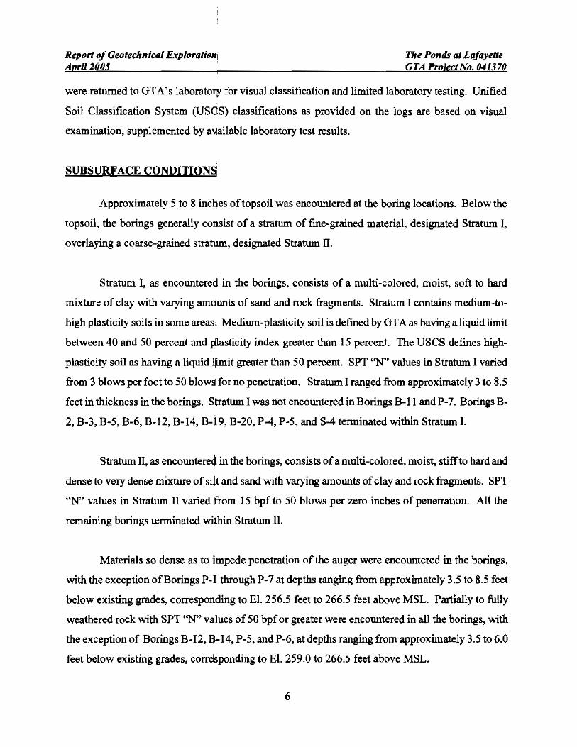
Please refer to the Table B-1, "Swnmary ofAuger Refusal and Weathered Rock" and boring
logs provided in Appendix 8 for further information. Idealized soil profiles representing the
subsurface information have been prepared and are presented as Figures 4 through 9 within
Appendix A.
LABORATORY TESTING
Selected samples recovered from the borings were submitted for limited laboratory analysis,
including natural moisture deteI1l)ination and testing for mechanical properties for classification in
accordance with the USCS, moisture-density relationship (proctor) testing and California Bearing
Ratio (eBR) testing.
Soils moisture contents for selected near-surface samples were detennined to range from 11.1
to 20.6 percent. Soil moisture contents averaged 13.2 pereent.
Two samples were submitted for grain size and index property testing to be classified in
accordance with the uses. The results ofthc testing are swnmarized in the following table:
Table I SUMMARY OF LABORATORY TESTING
BORING NO. DEPTH (It) USCS CLASSIFICATION LL% PI""
B-2 10-2.5 Fat CLAY, Ultle Sand (CH) 78 52
P-1 1.0-5.0 Lean CLAY Some Sand (CL) 36 15 ..
Note. LL LiqUId Lilmt PI Plastic Index
7

Report ofGeotechnical Exploration The Ponds at Lafayette April 2005 GTAProjectNo.041370
The bulk sample obtained from Boring P-l was also tested for moisture-density relationship
in accordance with the Standard Proctor modified as per Virginia Test Method for Laboratory
Determination of Theoretical Maximum Density Optimum Moisture Content of Soil, Granular
Subbase, andBase Materials (VTM-I). Additional1y, a CBR test was performed in accordance with
Virginia Test Method for Conducting California Bearing Ratio Test (VTM-8) on the same soil
sample collected from Boring P-l, eompacted to approximately 99 percent ofthe Standard Proctor
(VTM-l) maximum dry density for the tested sample. The results ofthe Standard Proctor and CBR
testing are as follows:
Table II SummarY of Moisture - Densitv Relationship
MaXimum Optimum Natural Dry Moisture Moisture CBR-
Boring Depth Donolly Content Content Soaked No. IIi.) 'Deft' 1%1 1%) 1%1
P-1 1.0-5.0 112.3 16.9 18.2 3.6
Please refer to the laboratory test data provided in Appendix C for further information.
CONCLUSIONS AND RECOMMENDATIONS
Based upon the results of this exploration, it is GTA's oplTIlon that the proposed
improvements are feasible, given that the following recommendations are observed. and that the
standard level ofcare is maintained during construction. However, medium- to high-plasticity soils
will possibly be eneountered during foundation excavations, slab and pavement construction that will
require removal and replacement. Also, undocumented fill materials from the filled-in old pond may
be encountered in the building and paved areas that will require removal and replacement. In
addition, shallow roek will be enoountered along the triple RCP that may require ripping or blasting.
GTA's reeommendations for foundation support and other geotechnical eonsiderations are
transmitted in the following paragraphs.
8
Report ofGeotechnical Exploration The Ponds at Lafayette April 2005 GTA Pro;ectNo. 041370
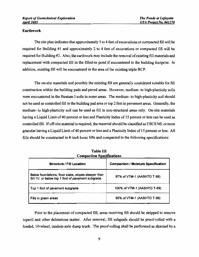
Earthwork
The site plan indicates that approximately 3 to 4 feet ofexcavations or compacted fill will be
required for Building #1 and approximately 2 to 4 feet of excavations or compacted fill will be
required for Building #2. Also, the earthwork may include the removal ofexisting fill materials and
replacement with compacted fill in the filled-in pond if encountered in the building footprint. In
addition, existing fill will be encountered in the area of the existing triple RCP.
The on-site materials and possibly the existing fill are generally considered suitable for fill
construction within the building pads and paved areas. However, medium- to high-plasticity soils
were encountered in the Stratwn I soils in some areas. The medium- to high-plasticity soil should
not be used as controlled fill in the building pad area or top 2 feet in pavement areas. Generally, the
medium- to bigh~plasticity soil can be used as fill in non-structural areas only. On-site materials
having a Liquid Limit of40 percent or less and Plasticity Index of 15 percent or less can be used as
controlled fill. Ifoff-site material is required, the material should be classified as USCS ML or more
granular having a Liquid Limit of40 percent or less and a PLasticity Index of 15 pereent or less. All
fills should be constructed in 8-inch loosc lifts and compacted to the following specifications:
Table III omDaction SDeCI leaIiODSC S'li
Structure I Fill L..oc::ation Compaction I Moisture Specification
Below foundations, floor slabs, slopes steeper than 97% of VTM-1 (AASHTO T-99) 5H:1V. or below top 1 foot of pavement subgrade
Top 1 foot of pavement subgrade 100% ofVTM-1 (AASHTO T-99)
Fills in green areas 90% of VTM-1 (AASHTO T-99)
Prior to the placement of compacted fill, areas receiving fill should be stripped to remove
topsoil and other deleterious matter. After removal, fill subgrade should be proof-rolled with a
loaded, lO-wheel, tandem-axle dump truck. The proof-rolling shall be performed as directed by a
9

Report ofGeotechnical Explo,ation Tlte Ponds at LafayetJe Ap,U2005 GTAProjeclNo.041370
geotechnical engineer or hislher qualified representative. Soft, yielding subgrade will require over
excavation to stable natural soil and replacement with compacted filL No fill should be placed until
the subgrade is approved by the geotechnical engineer. Fill construction should be monitored by a
professional engineer or hislher qualified representative. All compaction efforts should be verified
by in-pLace density testing.
The on-site soil will most likely require moisture conditioning prior to compaction efforts
in the fi II area. Depending on the time of construction, moisture may have to be added in some
instance or need to dry, if the soil is significantly over optimum moisture. As an altemate to
spreading, lime may be used as an admixture to dry the soil and compact to the specifications
outline above. Based on GTA's experience on similar materials in Fairfax County, GTA
recommends that 2 to 5 percent lime content (dry writ base) to dry the soil possibly to improve
the subgrade condition at the site. Five percent dry weight is equivalent to a spread rate of
approximately 48 pOWlds of lime per square yard, 12 inches deep compacted to 100 percent of
the Standard Proctor maximum dry density.
GTA recommends that the lime treated subgrade be constructed and cured in accordance
with Virginia Department of Transportation (VOOT) Section 307 specifications. The lime
treated material subgrade should bc compacted to at least 100 percent of the Standard Proctor
(AASHTO T-99) maximum dry density. Additional laboratory testing will be required to
detennine the lime pcrcentage that can be compacted to 100 percent of the Standard Proctor
compaction level and achieve the desired strength.
The subgradc should be proof-rolled prior to stabilization. Probing should also be
performed to verify thickness ofwet, unstable material. Localized areas may require additional
treatment. Soil lime and pavement construction should be monitored by experienced engineering
professional. Heavy construction traffic should be prohibited for a period of seven days after
completion.
10
Report ojGl!otl!chnical Exploration TIll! Ponds at Lajaydtl! AprUJ005 GTA Proll!ctNo. 041370
The work for the projeet should be performed in accordance with the guidelines presented in
the Fairfax County Public Facilities Manual. The buildings will be constructed under the guidance
of the Critical Structure Program due to the proposed structural steel construction.
Subsurface Utilities
The medium stiff to hard and medium dense to very dense natural soils are considered
suitable for support ofthe proposed utility system. GTA recommends thata 6-inch granular bedding
be placed beneath the pipe to provide uniform support when the pipe is supported on clayey soil,
rock, or when groWldwater is encoWltered. The proposed utility invert elevations may encounter
competent rock. In addition, very dense partially weathered rock were encountered in all the borings,
except Borings B-12, B-14, P-5, and P-6, at depths of approximately 3.5 to 6.0 feet below the
existing surface, eorresponding to £1. 259.0 to 266.5 feet above MSL. Therefore, difficult
excavations should be expected during the installation of the utilities, especiaLLy the proposed
relocated Rep.
Groundwater was not encoWltered in any ofthe borings, except Borings B-2, B~ 13, and B-15
direetly after the completion ofdrilling. However, perched groundwater may be encountered during
utility installation. Contractors should provide construction dewatering devices and adequate earth
support systems in the utility treneh excavations. Utility pipe systems below pavement and structural
areas should be backfilled using controlled, compacted fill, constructed in accordance with the
earthwork recommendations. The contractor should anticipate elevated soil moisture that will
require drying of backfill to meet compaetion specifications.
Compaction of the soils to the degree specified in the Earthwork section of this report may
require that the soils be moisture conditioned prior to placement and compaction within the treneh.
If the exeavated materials are wet of the optimum moisture content, they should be spread in thin
layers and aerated by discing to within 2 to 4 percentage points ofthe optimum moisture. Ifsoils are
not dried, suitable borrow material will need to be imported from other areas of the site for utility
treneh backfill. If the excavated materials are dry ofthe optimum moisture content, they should be
11

Report ofGeotechnical ExploraIWn The Ponds at Lafayetk AnrUl005 GTAProjectNo.041370
carefully hydrated prior to reuse. Settlement and instability are likely if the on-site soils are used as
backfill at moisture levels more than 4 percentage points above or below optimum
Foundations
The buildings may be supported on shallow spread footings designed for a net allowable
bearing pressure of2,500 pounds per square foot (pst). Minimum widths for wall footings of 16
inches and column footings of30 inches are recommended when design based on 2,500 psfresults in
a more narrow footing. Settlement on the order of 1 inch total and Y2 inch differential can be
anticipated based upon this design. Exterior footings should be founded a minimum of 30 inches
below the final exterior grades to provide protection from frost action, unless otherwise required by
local code.
Footings should be supported on the stiff to very stiff, low plasticity, fme-grained soils of
Stratum l, the medium dense to very dense, more coarse-grained soils ofStratum n, or on controlled,
compacted fill, helow any soft or loose near-surface soils or existing fill. Loose/soft near surface
soils or existing fill are not considered adequate for direet foundation support. The near surface
loose/soft layers or existing fill should be compacted in-place in accordance with the earthwork
recommendations or excavated to a stable stratum and backfilled with controlled, compacted fill.
Rock may be encountered at or above footing subgrade, especially for Building #2. 1be rock
should bc overexcavated by 6 inches below the design footing bottom. The overexcavated areas
should be backfilled with sand to design subgrade, in order to provide a "sand cushion" for unifonn
support. Blasting to remove rock from the footing should be perfonned prior to any concrete
construction. GTA recommends that a blasting contingency be established for the site.
Although, existing fill materials were not encountered in the borings, existing fill materials
are likely to be encountered in the filled-in old pond area in the western portion of the site and in the
area of the existing triple Rep. Generally, existing fill is not considered adequate for direct
foundation support. GTA recommends that a contingency he established to perfonn test pits to
12

Report ofGeotechnical Exploration The Ponds at Lafayelle Apri/200S GTAProieetNo.041370
evaluate the extent and depth of the fill placed for the old fann pond and to asccrtain ifexisting fill
materials are underneath Building #1 footprint. If existing fill materials are encountered during
fOWldation excavations, the existing fill should be completely removed and grade should be
reestablished in accordance with the earthwork recommendations.
Medium-to high-plasticity soils were encountered in some areas. Therefore, it is likely that
these types of soils may be encountered during foundation excavations. Thesc soils are not
considered adequate for direct foundation support. If medium- to high-plasticity soils are
encountered at footing elevations they should be overexcavatcd an additional 2 feet below proposed
footing bottom and baekfilled with controlled, compacted fill. The top of the high-plasticity soil
layer under the footing should be at least 4 feet below the final exterior grade.
Footing excavations sbould be reviewed by GTA prior to concrete placement. Penetration
testing should be perfonned upon exposed footing subgrades to confirm the allowable bearing
capacity. Particular care should be taken during the foundation inspection for the larger building
especially near the western portion of the site to locate areas offill materials. If the fiLL materials are
encountered dming the inspection they should be completely removed and replaeed with eontrolled,
compacted fill. In addition, the soil below the footings should be evaluated to detennine the
presence ofmediwn- to high-plasticity soils that will require special considerations. Footings shOuld
be conereted on the same day they arc excavated.
Seismic Information
Utilizing the SPT data from the field exploration and the guideline set forth by the 2000
International Building Code (!BC 2000 ~ Table 1615.1.1), the subsurface soils at the site is classified
as "Site Class C".
13

Report ofGeotechnical Exploration The Ponds a1 Lafayene April 2005 GTAProjeetNo.041370
Floor Slabs
Floor slabs should be designed as concrete slab-on-grade. The typieal slab consists of4 to 6
inches ofconcrete reinforced with welded wire mesh. The thickness ofthe concrete slab will depend
upon the antieipated traffic and subgrade support. GTA reeommends a design soil support K.'l Value
(Modulus of Subgrade Reaction) of 100 pounds per cubic inch for the competent, natural sand, silt
and elay materials. We recommend that the eoncrete floor slabs supported on grade be founded on a
four-ineh open graded washed gravel or stone layer covered with a polyethylene vapor barrier to
interrupt the rise of moisture through the slab.
Medium- to high-plastieity soils are likely to be encountered at the slab subgrade. In
addition, existing fill assoeiated with the fiLLed-in pond and existing triple RCP may be encountered
at slab subgrade. When slab subgrade consists of medium- to high-plastieity soil or existing fill,
overexeavation will be required. The medium- to high-plasticity soil or existing fin should be
overexcavated by at least 2 feet and replaced with controlled, eompacted fill.
Floor slabs should not be rigidly connected to fOWldation walls so that slight movements of
the wall will not affect the slab. Control joints should be provided to control shrinkage cracks ofthe
eonerete floor system.
Retaining Wall
Based on the site plan. GTA Wlderstands that a retaining wall is planned west ofBuilding #2
for the site. The proposed retaining wall will be approximately 340 feet long with a maximum
exposed height of4 feet.
The retaining wall will not restrict the lateral movement of soil backfill, and as a result, the
full internal resistance of the soil will be mobilized. We therefore, recommend the use of"active"
lateral earth pressure criteria for the retaining wall. GTA recommends the following soil parameters
for design of the retaining wall:
14

Report ofGeotechnical Exploration The Ponds aL Lafayette April 2005 GTAProjedNo.041170
Phi ~ 30 degrees
Moist Unit WI. ~ 120 pef
Cohesion = 0 psf
For Unrestrained Wall (Retaining Wall)
Coeffieient of Aetive Earth Pressure, K. =-c 0.36
Equivalent Fluid Pressure, EFP = 40 pcfi'ft
Walls should be backfilled with non-plastic soils meeting AASHTO classificationA-2-4 or
more granular. The parameters recommended above are based upon: 1) adequate drainage of
backfill to prevent the accumulation of free water against the wall or within any part of the backfill,
2) exterior granular backfil1 capped with a 12 inch thick layer of impervious soil, and 3) surcharge
loadings from vehicles and other sources mwt he added to the stated lateral earth pressures. Care
should be exercised so that heavy compaction equipment does not damage the walls during backfill
operations.
Surcharge loads at the surface should be multiplied by 0.5 and superimposed on the
reconunended lateral loading. We reeommend a friction factor of 0.34 to resist against sliding for
the walls that are fOWlded on fine-grained soils. A friction factor of0.53 should be wed ifthe walls
are fOWlded on more coarse-grained soils.
The fomulation walls may be backfilled with on-site granular material, which meet the
following requirements:
20 percent maximwn passing a V.S. Standard #200 sieve
60 pereent minimwn passing a V.S. Standard #40 sieve
Angle of Internal Friction = 30 degrees (minimum)
15
Report ofGeotednkal Exploration Tire Ponds at Lafayette AprU200S GTA Projet:tNo. 041370
Bulk (wet) Density ~ 120 pcf (maximwn)
Plasticity = Non-Plastic
All fills behind the walls should be constructed in 6-ineh loose lifts and compacted to 95
percent ofVTM-1 (AASHTO T-99) maximwn dry density.
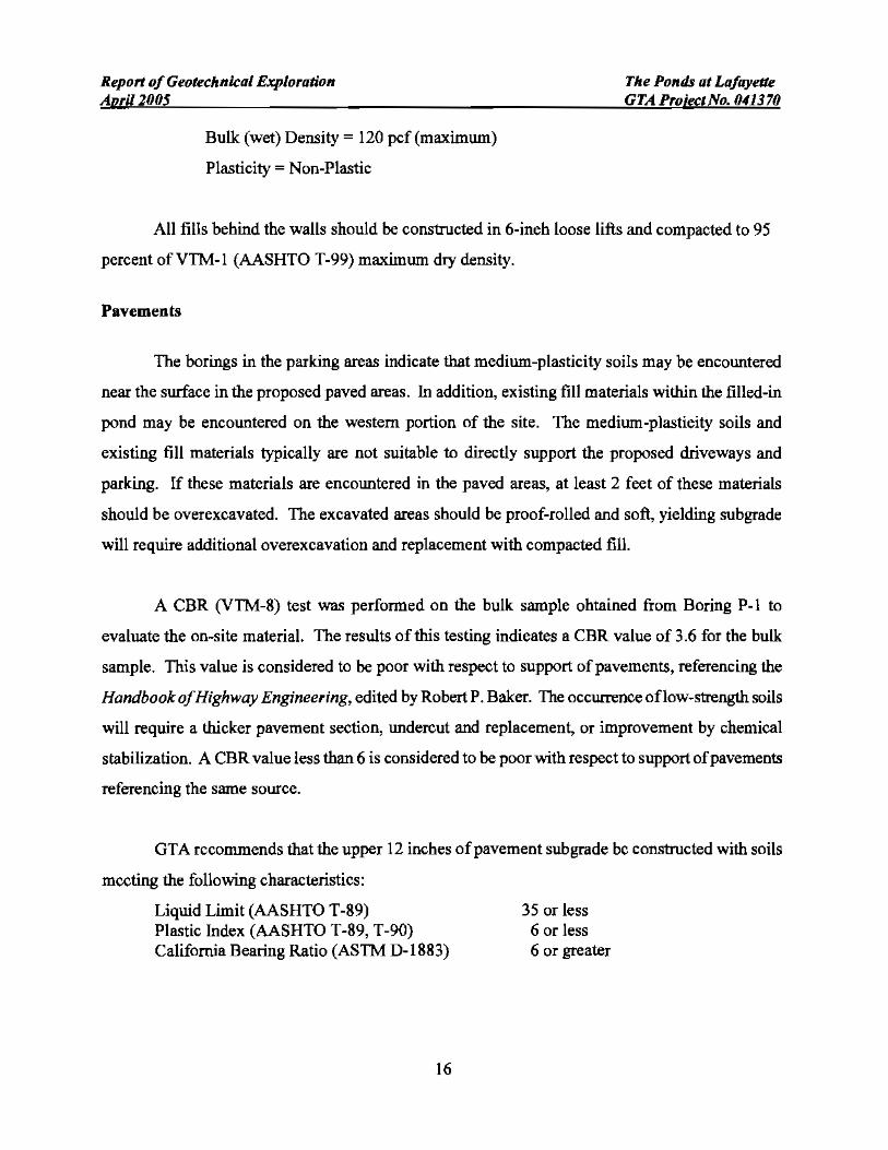
Pavements
The borings in the parking areas indicate that medium-plasticity soils may be encoWltered
near the surface in the proposed paved areas. In addition, existing fill materials within the filled-in
pond may be encoWltered on the western portion of the site. The medium-plastieity soils and
existing fill materials typically are not suitable to directly support the proposed driveways and
parking. If these materials are encoWltered in the paved areas, at least 2 feet of these materials
should be overexcavated. The excavated areas should be proof-rolled and soft, yielding subgrade
will require additional overexcavation and replacement with compacted fill.
A CBR (VTM-8) test was performed on the bulk sample obtained from Boring P-l to
evaluate the on-site material. The results of this testing indieates a CBR value of 3.6 for the bulk
sample. This value is considered to be poor with respect to support of pavements, referencing the
Handbook ofHighway Engineering, edited by Robert P. Baker. The occurrence oflow-strength soils
will require a thicker pavement section, Wldercut and replacement, or improvement by chemical
stabilization. A CBR value less than 6 is considered to be poor with respect to support ofpavements
referencing the same source.
GTA recommends that the upper 12 inches ofpavement subgrade bc constructed with soils
mccting the following characteristics:
Liquid Limit (AASHTO T-89) 3S or less Plastic Index (AASHTO T-89, T-90) 6 or less California Bearing Ratio (ASTM D-1883) 6 or greater
16

Report ofGeotechnical Exploration The Ponds at Lafayette April 2005 GTAProiectNo.041370
GTA recommends that materials in cut areas not meeting these guidelines be removed from
the top 12 inches of pavemcnt subgrade and replaced with suitable materials compacted in
accordance with the carthwork recommendations. Alternatively, the materials can be improved by
chemical stabilization.
Grain size, plasticity testing, and CBR tcsting should be performed on subgrade material
before placement ofgraded aggregate base. Additional testing will be required on subgrade material
ifchcmical stabilization is performed.
ADDITIONAL SERVICES
We recommcnded that during construction ofthe subject project, a geotechnical engineer be
retained to provide observation and testing services for the foLLowing items.
• Review final site and architectural plans to evaluate if they conform with the intent of this report.
• Provide testing observation and services during fill placement to evaluate if the work is being performed in accordance with the project specifications and intent of this report,
• Observe the proof~roUing of fill and roadway subgrades prior to placing fill or base course to evaluate stability.
• Review excavatcd footings for compliance with the project drawings and thc intent of this geotechnical report.
• Others as necessary.
LIMITATIONS
This report. including all supporting boring logs, field da~ field notes, laboratory test data,
calculations, estimates and other documents prepared by GTA in connection with this Project have
been prepared for the exclusive use of Moore & Associates, Inc. pursuant to agreements between
GTA and Moore & Associates, Inc. in accordance with generally accepted engineering practice. All
17

Report ofGeoreclinkal Exploration Tile Ponds al LafayetJe ADril2005 GTAProi«tNo.041370
terms and conditions set forth in the Agreement and thc General Provisions attached thereto are
incorporated herein by reference. No warranty. express or implied, is made herein. Use and
reproduction ofthis report by any other person without the expressed written pennission ofGTAand
Moore & Associates, Inc. is unauthorized and such use is at the sole risk of the user.
The analysis and recommendations contained in this report are based on the data obtained
from limited observation and testing of the encountered materials. Test borings indicate soil
conditions only at specific locations and times, and only at the depths penetrated. They do not
necessarily reflect strata or variations that may exist bctween test boring Locations. Consequently,
the analysis and recommendations must be considered preliminary until the subsurface conditions
can be verified by direct observation at the time of construction. If variations of subsurface
conditions from those described in this report are noted dwing construction, recommendations in this
report may need to be re~evaluated.
In the event that any changes in the nature, design, or location ofthe facilities are planned. the
conclusions and recommendations contained in this report should not be considered valid unless the
changes arc reviewed and conclusions of this report are verified in writing. Geo-Technology
Associates, Inc. is not responsible for any claims, damages, or liability associated with interpretation
of subsurface data or reuse of the subsurface data or engineering analysis without the expressed
written authorization of Geo-Technology Associates, Inc.
The scope ofOur services for this geotechnical exploration did not include anyenviromnental
assessment or investigation for the presence or absence ofwetlands, or hazardous or toxic materials
in the soil, surface water, groundwater or air, on or below or around this site. Any statements in this
report or on the logs regarding odors or unusual or suspicious items or conditions ohserved are
strictly for the information ofour Client. An environmental site assessment was conducted for this
site, which addresses environmental eoncems, and is trWlSmitted under separate cover.
18

Report of Geotechnical Exploration The Ponds at Lafayette AorU2005 GTA ProjectNo. 041370
This report and the attached logs are instruments ofservice. The subject matter ofthis report
is limited to the facts and matters stated herein. Absence of a reference to any other conditions or
subject matter shall not be construed by the reader to imply approval hy the writer.
041370 GEO-TECHNOLOGY ASSOCIATES, INC.
19

lmportant Information About Your
GlIOl8dInIl:alllorvlcea Arl PIII'IlImI" I... Bpdc .......011•• P8I'8IInB.... PI'lIIIet8 Geotechnical engineers structure their servioos to meet the specific needs 01 111eir clienls. Ageotechnical engineering sludy conducted for acivil enginoer may nollullill the needs 01 aconstruction contractor or even another civil engineer Becaus5" each geotechnical engineering study is unique. each geotechnical engineering report is unique, prepared so/e/ylor the client. No one except you should rely on your geotechnical engineering report wilhout IIrsl corJlerring with [he geotechnical engineel who prepared il. And no one - (/01 even you - should apply the report for any purpose or ~roiecl
except the one originally contemplaled.
RBlId 1hI Full RIIPOl'I Serious problems have occurred because those relying on ageolechnical engineering repO!! did not read it all. Do nol rely on an executive summary Do not read selected elements only.
AGllIlIc:IInIcaI fQmItII'hIllllllPBl'lll B••ed .n AlInIqu. BIt 01 ProJect-BplclllC FactIll'S Geotechnical engineers consider anumber of unique. project-specific factors when eslablishing Ihe scope of a study, Typical factors include lhe client's goals, objectives, and risk managemenl preferences: the general nature of the struc!uro Involved. its size, and configuration: the location of ltle struclure on the site: and olher planned or existing site improvements, such as access roads, parking lots, and underground utilities. Unless the geotechnical engineer who conducted the study specifically indicales otherwise, do nOI rely on ageolechnical engineering reporttha\ was' • nol prepared for you, • nol prepared lor your project. • not prepared lor the specific sile explored. or • compleled l.lefure Inlporlant projecl changes were madE
Typicol cllallges lIlal call erode IIle reiiability o! all 8xisling gootedmical engineering reporl include lhose Ihal affect: • the function 01 lhe proposed struclure, as when it's cllanged Irom a
parking garage to an office building, or from alight induslrial plan( 10 arefrigerated warehouse,
• elevation. configuration, localion, orientation, or weighl of Ihe proposed slruclure,
• composition o( lhe design learn, or • project ownership
As ageneral rU,le, J!ways inlorm your geoteChnical engineer of project changes---even mirlOr ones-----i3.nd request an assessment of their impact. GfJolechnical engineers cannot accept responsibility or liability for problems Ihal occur because their reports do no! consider developments of which IIley were noi inlol/ned.
Sub8llrlace C.nd/llOlls Can Change Ageotechnical engineering report is based on conditions {nat exisleu al the lime the study was performed. 00 not rely on ageotechnical engineering reporl whose adequacy may have been a!fected by: Ihe passage of lime; by man-made events. such as conslrllction on or adjacenlto the sile: or by natural events, such as floods. earlhquakes, or qroundwaler fluclua" tions. Always contact lhs geotechnical englfleer before applying Ihe report 10 determine if it is still reliable. Aminer am'Junl 01 addilional tesling or analysis could prevenl major problems,
MoB! Geotechnical fmdIntIB Are PrBfessional Opinion. Site exploration identi1ies subsurface conditions only allhose poinls where subsurface tesls are conducted or samples are laken, Geotechnical engineefS review field and laboratory data and then apply their professional judgmenllo render an orinlonabout subsurface conditions IhroughOul the sile Actuaf subsurlace conditions may differ-sometimes significanllyfrom those indicaled in your report, Relaining the geotechnical engineer who developed YOLir report 10 provide construction observation is the most eflecti...-e method 01 managing the risks assoclaled wilh unantiCipated condilio.'1s.
AKepol'l's Recommendaliun. Ar. NIIt Rnal Do nol overrely on lhe conslruction recommendations included ill your report. Those recommenda/lons are not final, because geotechnical engineers devefop them pr,incipally trom Judgmenl and opinion Geotechnical engineers can linalize their recommendations oilly by observing actual
'-I

APPENDIX A
FIGURES

---
..M:
, D LLE~
I I
\ ,1/l
I/
I
V' ER AllO
i <I
1/""--<---<'
.~ ~=---
Gatll 2'>
I,
" ,I ;"11 !II
,.....•IIII
AirUp~ St_FUdlo
, • YDOTN<lV lUndlfCDn\_~'-''A DistHdq <jI..~
-~ ." . "~~.w';;;~ .,; '4:J.. OJ "~!S!!T ~':~503~F~IG~U::,:R:::E:";1~f ,~U1~P~~~~~:~~T~~@~~~~~:~:::";:"r·-~~T:he~pondS at Lafayette GA SITE LOCATION MAP
Fairfax Coun Iy• Virginia
SCALE DATE REVIEWED BY PROJECT NO.
Approx. , 041370.V1"=2000' April. 2005 ADC AR

BLANK
GEO·TECHNOLOGY ASSOCIATES, INC, Geofachnicsl fJnd Environmental Consuflanls
45064 Underwood Lane, Suite A Slerllng, Virginia 20166 (703) 478-0055 Fa:ll: (703) 478-0137
",,'f" 'J. ;.....-'\1I' ~-,,_, ,
7JB 1 ~
(
FIGURE 2
The Ponds at Lafayette
SITE SOILS MAP
Fairfax County, Virginia
SCALE DATE SOURCE REVIEWED BY PROJECT NO.
Approx 1" = 500' April2005 Fairiax County Soils Ma AR 041370V

------------
~ 100 290 300 100 ;;00 OQQ 700 800 I I , ···1290
f:\pp.r:Q.~'m~ie ..1,..imj1~ .Q.~ ..28: BUilding ~2 2-StOlY ",..
Buil~ing
2, 12..
21: 275 Finii:>hed Floor
Elevation =265.5• ~"'=I'p-, !- ' ~ 271 ",'",.'' '!l -.' > .!! ?------] ~~i5~;;.-( ,,". r I • ~Co~trolled Fill .APpm~i";~I~ "'"""Approximale, m' "'"
w , iJrj""""/"" • p' EXlsling ,1270
... ,- ... , .'- ·12652 =~,;.':c:~;:::~,~ "",' ,,'c:':~Grade / ~
_~"::<~~.~~C:~ ~'-'-T" "'~ ~ " //;., ,eo", Stratum II 5014..... --..::.---- : ,..... ,.. --~' om1....
, 1255
Approximate ;Top of Rock
250
1\ 1M m ~ DIiI fJ\1) ml 100 AM 1245,..·------T---,iOO---2i!O---~il-__;:=~'::_~~~---,OO---"!O---WO-----__J Di!'1ance Along Baseline
GEO-TECHNOLOGY ASSOCIATES, INC. The Ponds at Lafayette OEOTECHNICAL AND E...,..,tROIolMENTAL CONSULTANTS
SUBSURFACE PROFILE DIAGRAM 45094 UNDERWOOD lANE. SUITE A
STERLING. VIRGINIA 20166 SECTION A-A (703)-418-0055
FAA (703)-478-tl131 Fairfax County, Virginia
SCALE IREVIEWED BY I PROJECT# I DATE I FIGURE
~ HORZ: 1" = 120' VERT: 1w = 10' AR I 041370.V I Aprll2005 f 4I

I
• ... ·1290
ApPfQ~!m<;l.tl;l. ,~!rn(~s Qf. .:. _.. Building #2 2-Story ,
Building
Appro)(im~te Limits of HWrdlii9:#" "'";StOry"' .... ·1285
Btiilding
r .... 1280
27: ·'27S
-- Approximate < o
l '"
27< 1.:0..,.,:::::::.-:-::_
·-··E:~~~~~1:~~~:5l-· "-A'~C~7~~~!~a;Jj5 ·····1·······[··.·..~:~.. ···127' . : Approximate
.-1~ ·...·,<L~·~··~·~~d~~· '---12~
11 : -,_ .. _. -
---""'- ... ,,-.~-_.~.-:------? .. _". "260
25: Appr:oximate
--Topi)fRoCf(" Fat ....... bay' .. :.....
, -':- Stratum II
. -'Fat""Clay
, oIU/"'~
..... "' ..
'JlJ/4.5"' --:
7
·1255
. .. ,.. ··········1250
2451 1245o 100 200 W ~ ~ 600 700 W Distance Along Baseline
1~ 1- GED-TECHNOLO~Y ASSOCIATES. INC. The Ponds at Lafayette OEOTE;CHNICAL AND ENVIRONMENTAL CONSULTA."ll"S
SUBSURFACE PROFILE DIAGRAM .5064 UNDERWOOD lANE, SUITE A
STERUNG, VIRGINIA ro,6tj SECTION B-B (103)-476-00:55
FAX (703)-47B-0137 Fairfax County, Virginia
SCALE TREVIEWED BY PROJECT # DATE FIGURE
HORZ: 1- '" 120' VERT: 1" '" 10' AR 041370.v April 2005 5

" ........................, . ·1285
-'280
27! "1275
APProXimate, ApproximatE> . . ···1270Proposed Existing ,", IJ y'
. Grad:'. . .. .....[G de .1'65 - - ~-----. , 'rr·····, . ,26: -.'- - - - - - • - ------"'_ H .. M.;...., >' .;... ~=_=_ .....__ '" .
'i -- -:~."t--~:-="'~5tJ~-; ~umI: ""'""".• ~. 7 '7 . ' ~_.. - ". -- .•...'" - - - -" 50/""...;." . "/D.>"" "Sttat,m II ,.. ? . I
'!lJf4':... __';I
Fat : Fat __····day: ············':aay """:';';1-- . "255
Approximate Tali ofRock "250
.,.'- ,.. ..,_. "245
2401 1240D SO. 1/10 150 200 2M 3M 350 0i00 150 50il 550
Distanc! Along Baseline
GEQ-TECHNOLOGY ASSOCIATES, INC. The Ponds at Lafayette GEOTECHNICAL AND ENVIRONIIlENTAL COI'lSULTANTs
SUBSURFACE PROFILE DIAGRAM 45064 UNDERWOOD LANE, SUITE A
STERLING. VIRGINIA 20168 SECTION C-C (Relocated RCP) (103;-478-0055
FAX(10J)-47l1-{1137 Fairfax County, Virginia
SCALE REVIEWED BY PROJECT # DATE FIGURE
HORZ: 1-:: 80' VERT: 1~ = 10' AR 041370.v April 2004 6---"

- ---
I o 50 150
28: ",., Approxi.r.ate Limit~ Of
" ,$uildiog,#l,'·story!>oildiog\" """"" ·'280
... ;_ , :Y•:
27: ""275 I:...' APproximat~ Limits of Parking :'. I
Approximate:Area
", ,
;,~rnP.9.~_~,-=Firrisbed"FIoor': ..... ,.", .. , "270 ~
Elevation = 266.5 ~:G..de 1
-' _..*,1 ...-1:>-7_I,::-:-::: :-::-. ",o,",_L",~;::_" ....._;.(.,,:._.,.,..... _
'~.¢i~YiO'ti~~tRlr.:~<,~;:~':"- ,ApproXImatec
0 , ..::.... ...i!:..M . .,..,:•••r --- .. _--.: .... ,,~~i.~!n.g "265........,.'-_-"i'-,."...:.:::.-~.'6 ....1_. , ._" .• "'-:.,""-~;~,"':_c:~,' __ """'·-~~N":·""··· ...··'''·,··,· ~.,.... -...
';.~~.·~:.;r~.p'<t~:;S-'1·:,~Q, . -~ _
>•'"
..... 501. GradeIl~ '- -~,='"- -!lOti',- . ,_ _.1, .~/(-. SD7r--? t . . 50"/1·'1 1'60• :StraturTj"j ,""" ·!F····:":":>::
Fat-./ -:-----~--,.: Stratum II: ",..,.... _... ;.__ ....... _,.. __ '.J.
T'_
Clay""ApprQximate Top ci;t fiock
'Appl"tl~mate .....•.. ,1250
Top o(Rock
·'245
10 1240 o ~ 100 1~ m ~ ~ 3M @ & W 5~
Distance Along Baseline
GEO-TECHNOLOGY ASSOCIATES, INC. HIe Ponds at Lafayette GEOTI::CHNICAL AND EN\lIRONMENTAL CONSULT......nS
SUBSURFACE PROFILE DIAGRAM 450&4 UNDERWOOD lANE. SUITE A
STERLING, VIRGINIA 2D' 6li SECTIOND-D (103)-416-0055
FAX {103H18-l1131 F· C V" .alffax ounty, Irgmla
~LE I REVIEWED BY I PROJECT# I DATE I FIGURE
Il- .JL HORZ, '" = 80' VERT, ," = 10' [ AR I Q4'370V I Apnl2005 I 7 I

2SO 300 350 iOO @ m OW I I
159 200 .. .. '" o 59 100 . ... ....... ,.. . ..............•.... ... ;.. - - - ; - - . - - - - _. - - - > ••••••••••• -,,; •• - ••~.,
. '280
Approximate - - ,- ----·········,·.······12.75" ApprOXimate"E~:~:9 "\- ""I"~'" ,,- -;.- '~~~~~ji~~_~t~~t~~;~~~~ :.. 1
Proposed Grade", ···1270
P-5 M -..-=- i-:::-..---j - --:"" - - -- - - Finished Fleor Elevation = 266.5 c
•io
, ·~:z:;::::*}:~f££Ei;:2~±:;;;i3'~~tLq~)~~~J(i\7~;f~:~~t ···1265 ~ . Stratum I ~::53 : : WZIIl :"-- """"'-::':':":;';'~'::"':':'<::::"''''':'''
17 :.-----1: . :-Ji5D/4.$····_·~ .Il., lz6O ______ 7
? I:50/0· "'~.· . .
· . .Fat Pi!. ?· .J ___ . 5l1O _.. ·1255-Faf~"Clay ~ppro~j~a~· .. ....:... :Fat Clay: Clay
.}QP.Qf.R.Q.cK .. _ ··'250
"2.065
~ Iw o M 100 19 200 2M ~ 3~ @ ~ 500 5~
Distance Along Baseline
I ~ I IGEO-TECHNOLOGY ASSOCIATES, INC. The Ponds al Lafayette - - GI<OTECHNICAL AND ENVIRONMENTAL CONSULTANTS
SUBSURFACE PROFILE DIAGRAM 45Oll4 UNDERWOOD l..,6JIIE, SUITE A
STERLING. VIRGINlA201fll1 SECTION E-E (703}-478-0055
FAX (703}-478-ll131 Fairfax County, Virginia
. I I I SCALE REVIEWED BY PROJECT. DATE ~FIGURE
L HORZ: 1" '" 80' VERT: 1" - 10' AR 041370V Apri12005 I 8 -----.--J

350
" --. ',285
"280
~I
27~
ApproxImateE'Xlstln9 \ Grade
. ~proxfmate limits of
BuUdlng #1 1~slory bUilding
---;... " ;.f ControlledFill
----1275
2701. Z -M . -, .,.···1270
c
1 w
- 7 -:-_ ~,'~,._. !.i~~he.dFI?Q~.~levation-266.5 /APproximate """" =W'...". ~'~~. . -,,-,"'-.. -.--".,.'"'''''' ." ,'c' . ,-~. ProposedV/M .. _ ,.",~. "-'~.,~ 7'»:
., 5t I" I'" I: """~"'<"'<'-''''',''-' Graderatl;lm 12 -....:;., ~/2. 1__ ..... __ _ 1 11 -
'"'...~..,_ II »/0.5" fIJ/U" '!IJ!3.5
··········1265
.........t*~_~.'!'!.: ,_ .. , 1260
Fat Clay
Approi<:imate" '''' Top of Rock
' ... 1250
"245
2-401 0 so 100 150 200 250 300 35d 400 450 500 S50 1240
Distance Along Baseline
GE().TECHNOLOGY ASSOCIATES,INC. The Ponds at Lafayette GEOTE<;;HNICAI.. A"'O EHVIRON~ENTALCONSULTANT:S
SUBSURFACE PROFILE DIAGRAM 45064 UNOERWOOD LANE, SUITE A
STERUNG. VIRGINIA 20166 SECTION F-F (703}-478-0055
l HORZ: l' '" 80' VERT: 1" = 10'
SCAlE
FAX (703}-<171Hl137
REVIEWED BY
AR
Fairtax County, Virginia
PROJECT~ DATE ~~U=R=E---11
041370.v I April 2005 I 9

APPENDIXB
SOIL BORING LOGS

NOTES FOR EXPLORATICN LOGS
KEY TO USCS TERMINOLOGY AND GRAPH'C SYMBOLS SYMBOLS
MAJOR DIVISIONS (BASED UPON ASTM 02.487.QO] GRAPHIC LmER
GRAVEL GWAND
GRAVELYCOARSE SOILS GP GRAINED
MORE THAN 50%SOILS O'COARSE GRAVELS WITH GM FRACTION
FINESRETAINED ON NO, 4 SIEVE
(MORE THAN 15% PASSING THE NO, 200 SIEVE) GC
SAND CLEAN SANDS SWAND
t.lClRC THAN 50% SANDY OF MATERIAL IS (LESS THAN 15% PASSING THE NO, 200 SIEVE) .' .•. '.< . SPSOILS .. ' .'.' ,lARGER THAN NO, 200 SIEVE
,'-' >.MORE THAN 50%51'" SANDS WITH SMOF COARSE ;' " .'. .FINESFRACTION
PASSING ON NO. (MORE THAN 15% PASSING THE NO, 200 SIEVE) SC4 SIEVE
SILT OReLAY ML«15% RETAINEO THE NO. 200 SIEVE)SILTS FINE AND SILT OR CLAY WITH SAND OR GRAVEL
GRAINED CLAYS 115% TO 30% RETAINED THE NO, 200 SIEVE) CL SOilS
LIQUID Ut.lIT SANOY OR GRAVELY SilTOR CLAY LESSll-IAN 50 (>30% RETAINED ll-IE NO. 200 SlEII'E) OL
SilT OR CLAYSilTS MH«15% RETAINED THE 1010.200 SIE....E)'-lORE THAN 50% ANDOF tMTERI.IL IS SILT OR CLAY WITH SAND OR GRAVELSMAlLER "THAN CLAYS
(1&% TO 30'110 RETAINED THE NO. 200 SIEVE) CHNO. 200 SIEVE SIZE L1aUID L1t.lIT SANDY OR GRAVELY SilT OR CLAY
GREATER THAN 50 (>30'110 RtTAI"lEOTl-lE "l0. 200 SIEVE) OH
HIGHLY ORGANIC SOilS PT
toOTE: DUAL SYlIIBOLS ME USED TO l"lDICATE BORDERLINE SOIL CLASSIFICATIONS
ADDITIONAL TERMINOLOGY AND GRAPHIC SYMBOlS
GRAPHICDESCRIPTION SYMBOLS
TOPSOil
ADDITIONAL I-------:-:~=::-:~------~~~ggj DESIGNATION MAN MADE Fill
GLACIAL Till
COBBLES AND BOULDERS
DESCRIPTION "N"VAlUE RESIDUAL
SOil DESIGNATION HIGHLY WEATHERED ROCK 50 TO 5011"
lESS THAN 5011"ARTIAllY WEATHERED ROCK AUGER PENETRABLE
COARSE GRAINfn ;'j(}, (GRA....EL AND SAND)
BLOWS PERDESIGNATiON FOOT (BPF!
"N"
VERY lOOSE 0·'
lOOSE 5-10
MEDIUM DENSE 11·30
DENSE 31 - 50
VERY DENSE >50
..NOTE: "I ....ALUE DETERMINED AS PER ASTM 01586
FINE GRAINED SOilS (SllT..,.O CLAY)
CONSISTENCY BP'
VERY SOFT <2
SOFT 2· ,
MEDIUM STlFF 5·8
STIFF 9 - 15
VERY STIFF 16·30
HARD >30
NOTE: AOOITIONAL DESIGNATIONS TO AOVANCE SAMPLER INOICATED IN BLOW COUNT COLUMN: WOH = WEIGHT OF HAMMER WOR =WEIGHT OR RODlS)
SAMPL.E TYPE
DESIGNATION SYMBOL
SPUT-SPOON S.
SHElBY TUBE u·
ROCK CORE R·
WATER DESIGr-;,t..TION
DESCRIPTION SYMBOl
ENCOUNTERED DURING DRILLING ~ UPON COMPlEnON Of DRilLING Z 24liOURS AFTER COMPlETION ~
NOTE: WATER OBSERVATIONS WERE MACE AT THE TIME INDICATED. POROSITY OF SOIL STRATA, WEATHER CONDITIONS, SITE TOPOGRAPHY, ETC. MAyeAUSE WATER LE ....EL CHANGES.
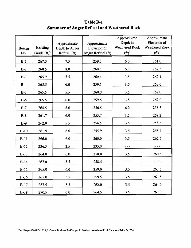
Table B-1 Summary of Auger Refusal and Weathered Rock
Approximate Approximate
Approximate Approximate Depth to Elevation of
Boring Existing Depth to Auger Elevation of Weathered Rock Weathered Roek
No. Grade (ftt Refusal (ft) Auger Refusal (ft) (ft)' (fi)'
B-1 267.0 7.5 259.5 6.0 261.0 ,
B-2 268.5 8.0 260.5 6.0 262.5 I
B-3 265.9 5.5 260.4 3.5 262.4
B-4 265.5 6.0 259.5 3.5 262.0
B-5 265.5 5.5 260.0 3.5 262.0
B-6 265.5 6.0 259.5 3.5 262.0
B-7 264.5 8.0 256.5 6.0 258.5
B-8 261.7 6.0 255.7 3.5 258.2
B-9 262.0 5.5 256.5 3.5 258.5
B-10 261.9 6.0 255.9 3.5 258.4
B-11 266.0 6.0 260.0 3.5 262.5
B-12 236.5 3.5 233.0 -- --
B-13 264.0 6.0 258.0 3.5 260.5
B-14 267.0 8.5 258.5 -- --B-15 265.0 6.0 259.0 3.5 261.5
B-16 265.0 5.5 259.5 3.5 261.5
B-17 267.5 5.5 262.0 3.5 264.0
B-18 270.5 6.0 264.5 3.5 267.0
L:\DocslReportU004\04lJ70_Lafsyo::llr Business ParklAuger Refusal and Weathered Rock Summary Table 041370

Table B-1 Summary of Auger Refusal and Weathered Rock
Approximate Approximate Depth to Elevation ofApproximate Approximate
Existing Elevation of Weathered Rock Weathered Rock Boring Depth to Auger No. Grade (ft)' Refusal (ft) Auger Refusal (ft) (ft)b (ft)b
B-19 271.0 6.0 265.0 3.5 2675
B-20 268.0 5.5 262.5 35 264.5
B-21 265.5 5.5 260.0 3.5 262.0
Pol 263.0 --- --- 3.5 2595
P-2 272.0 --- - -- 3.5 2685 I
P-3 264.0 --- --- 3.5 2605
P-4 265.6 - - - - - - 3.5 262.1
P-5 267.0 --- --- - - - --
P-6 264.0 --- --- -- - --P-7 2635 --- --- 35 260.0
S-l 261.5 6.0 255.5 3.5 258.0
S-2 263.8 5.5 258.3 3.5 260.3
S-3 2645 6.5 258.0 35 261.0
S-4 268.0 8.0 260.0 6.0 262.0
S-5 264.0 5.5 258.5 3.5 260.5
II (p_ 5'1
Notes: a - Elevation above MSL. Existing ground surface elevation were estimated from Fairfax County topographic maps.
b - "Weathered Rock" refers to partially to completely weathen:d bedrock with a SPT "N" value of so blows per foot, or greater.
L:"[)ocs\Reporl\200'l\041 nO_Lafayette Business Park'IAugcr Renlsal MId Weathered Rock Summary Table 041 370

Sheet 1 of 1 LOG OF BORING NO. B-1
PROJECT: The Ponds at Lafayette WATER lEVEL: '!¥. Dry ,J: Drv .i. PROJECT NO: 041370.V OATE, 12/21120041212212004 "':==-~-
PROJECT LOCATiON: fairfax County, VirgInia CAVED (ttl: 5.7 SA
DATE STARTED: December 21. 2004 GROUND SURFACE ELEVATION: 267.0 DATE COMPLETED: December 21,2004 DATUM: MSl
DRILLING CONTRACTOR: Free State Drilling, Inc. EQUIPMENT: CME 65 DRILLER: Free State Drilling, Inc. lOGGED BY: JS
DRILLING METHOD: HSA CHECKEO BY: NN SAMPLING METHOD: S lit Spoon
:[ §; w<r WE w> ~ z §; u~ ~w ~.E ~g~~ om Ow~" ~ ~ n.~
~~ ~ ~ ~~h "" e!z
w
~
~~ :Jig :Ji ~ l> Q ,,~
~ ~ ~ m w DESCRIPTION I REMARKS
267.0 0 CL Reddi9h brown, moist, stiff, lean CLA Y, some sand, trace rodt. Topsoil: 5 in.
fragmeRts. (el)
,81 10 '.&4"
264.0 ML Grayish brown, dry, stiff, Sandy SilT, some rock fragments.
• (Ml)3.5 2-4-118' "
5
, ,
IIII259.5 Auger Refu181@ 1.5 ft Waler not
encounteredEnd 0' [email protected], during drilling,
~•tIlOTES: Ground Surface Elevation Interpolated trom Site Plan provided by RDA
GEO-TECHNOLOGY LOG OF BORING NO. B-1ASSOCIATES, INC. 45064 Underwood Lane, Suile A Ip Sheel1 011
~ Sterling, Virginia 20166

Sheet 1 or 1LOG OF BORING NO. B·2
PROJECT: PROJECT NO:
PROJECT LOCATION:
DATE STARTED: DATE COMPLETED:
DRILLING CONTRACTOR: DRILLER:
DRILLING METHOD: SAMPUNG METHOD:
;[ w. w€ w~ .w .£ .. m ~~ .. ~~~ ~~ :I~ :I§ ~~
•w m
., 3-3-~'.0 10
6' 2-1-63.5 ,
.3 ,6.0 12-5014"
The Ponds at Lafayette 041370.V Fairfax County, Virginia
December 21,2004 December 21, 2004 Free State Drrlllng, Inc. Free State Drilling, Inc. HSA S lit SDoan
g
" g
~ ~
u.i'i -0~ "mI ~~ w ~~ z •w 0 ~~
0 CHJ~'5
, l,s
.::::~
,
263.5 5CL
50/4"
260,5
WATER lEVEL: Yl Dry :t. 6.3 Z'----__ DATE 12/211200412/22/2004 _
CAVED (n): 6.1 6.0
GROUND SURFACE ELEVATION: 268.5 OAruM: MSL
EaUIPMENT: CME 55 LOGGED BY: JS
CHECKED BY: NN
DESCRIPTION I REMARKS
Tannish brown. moist, medium stiff, fat CLAY, Uttle lend. (CH) Topsoil: 7 in.
I
Gr&:iish brown, moist, hard, lean CLAY, some sand. (race rock fragments. (eL)
Auger Refusal @8.0ft. Water nol encountemdEnd of Boring @ 8.0 ft. during drilling.
~ ;; NOTES: Ground Surface Elevation Interpolated from Site Plan provided by RDA
I'.GEO-TECHNOLOGY LOG OF BORING NO. B-2ASSOCIATES, INC.
45064 Underwood Lane, Suite A Sheet 1 of 1Sterling, Virginia 20166
"
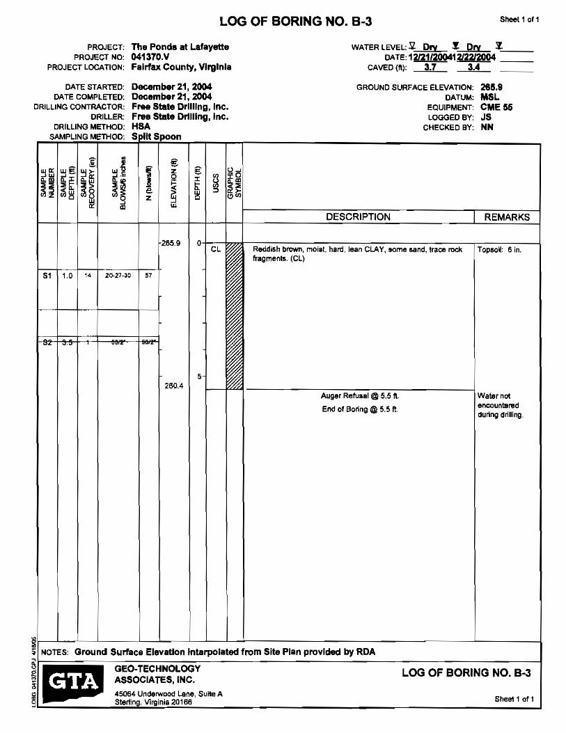
Sheet 1 of 1 LOG OF BORING NO. B-3
PROJECT: PROJECT NO:
PROJECT LOCATION:
DATE STARTED: DATE COMPLETED;
DRILLING CONTRACTOR:
DRILLER: DRILLING METHOD:
SAMPLING METHOD:
•;[ ~~ ~~
~~ ~~ ~> ~ .~~ ~m
~~ ~~ ~~ ~§~~ ~o ~ ~
~
I
., 10 " 20-27-30
The Ponds at Lafayette WATER LEVEL: 2 Dry .!. Dry 7.'---__ 041370.V DATE,12!21/200412/2212004 _ Fairfax County, Virginia CAVED (fl.): 3.7 3A
December 21,2004 GROUND SURFACE ELEVATION: 285.9 December 21, 2004 DATUM: MSl Free State Drilling, Inc. eQUIPMENT: CME 55 Free State Drilling. Inc. LOGGED BY: JS HSA CHECKED BY: NN S III Spoon
g I u~z g
I ~
t -00 ~
~ ~m ~ l;l
z ~ ~~ ~~
~
DESCRIPTION I REMARKS
265.9 0 CL Reddish brown, moist, hard, lean CLAY, lIome sand, Iraoe rock Topso~: 6 in.
fragments. (el)
"
5 260.4
Auger ReMal @ 5.5 fl.. Water not encountel'lclEnd of Boring @ 5.5 ft, during drilling.
~I ~ NOTES: Ground Surface Elevation Intarpolated from Site Plan provided by RDA
GEO-TECHNOLOGY LOG OF BORING NO. B-3 ;§IP. ASSOCIATES, INC.
45064 Underwood Lane, Suite A Sheet 1 ot 1Stef1ing, Virginia 20166
"

Sheet 1 of 1LOG OF BORING NO. B-4
PROJECT: PROJECT NO:
PROJECT LOCATION:
DATE STARTED: DATE COMPLETED:
DRILLING CONTRACTOR: DRILLER:
DRILLING METI-lOO: SAMPLING METHOD:
= w~ .W~
~~ w€ " w~
~w
~m ~;: ~
~. ~~ !~ :Ji~ :Ji8 ~~ w
•z ~
S, 1.0 7-13-25"
S, 3.' ,.. 50/C.6"
, 5010"S, '.0
The Ponds at Lafayette WATER LEVEl: £. Dry :t. Dry ~'-:::== 041370.V DATE: 12/21120041212212004 _ FaIrfax County, Virginia CAVEC (ft): 3.1 3.0
December 21, 2004 GROUND SURFACE ELEVATION: 265.5 December21,2004 DATUM: MSL Free Slam Drflllng, Inc. EQUIPMENT: CME 55 Free st.-t. Drtlllng, Inc. LOGGED BY: JS HSA CHECKED BY: NN Spilt SDOon
fg z g u~
0 00 I-0 I U mI;: 00 e
z
~
!!i " ~~ ~ w DESCRIPTION I REMARKS
265.5 0 CL Reddish brtMIo, moist, hard, lean CLAY, some sand, trace rock Topsoi!: 7 in.
fragments. (el)
"
262.5 Ml Reddish brown, moist, hard, Sandy SILT, little rock fragments.
(ML)0/0.5'
• 259.5 ~ .
SOlO" Auger Refusal @ 6.0 ft. Water nol encounteredEnd of [email protected].. durtng drilling.
,
§ ~ NOTES: Ground Surface Elevation Interpolated from Site Plan provIded by RCA§IIJ~ GEO-TECHNOLOGY LOG OF BORING NO. B-4 ~ If';' ASSOCIATES, INC.
~ 45064 Underwood Lane, Suite A Sheel 1 ot 1
...J Sterting, Virginia 20166

Sheet 1 "f 1LOG OF BORING NO. B-5
PROJECT: The Ponds at Lafayette WATER LEVEL: ~ Dry ~ Dry ::t'---__ PROJECT NO: 041370.V DATE: 121211200412122/2004 __
PROJECT LOCATION: Fairfax County, Virginia CAVED (It): 3.1 3.0
DATE STARTED: December 21,2004 GROUND SURFACE ELEVATION: 285.8 DATE COMPLETED: December 21, 2004 DATUftlI: MSl
DRILLING CONTRACTOR: Free State Drilling, Inc. EQUIPMENT: CME 65 DRILLER: Free State Drtlllng, Inc. LOGGED BY: JS
DRILLING METHOD: HSA CHECKED BY: NN SAMPLING METHOD: Split SnitOh
I, '" €~ ~ ,,~ w~
~w ~€ ~~ ~.5 € -0w~ • "",~'" ~~" ~~ ~ "I;:
~ ~~ Ii ~ ~~ ~~ ~~ ~8 ~o z w ~ "",w•
~ ~ ~ w
DESCRIPTION I REMARKS
265,5 0 CL Reddish brown, moist, hard, lean CLAY. some sand, trace rock Topsoil: 6 in.
fragments. (eLl
51 1.0 5-13<11 .."
5 260.0
Auger Refusal @ 5.5 fl. Waler not
End of Boring@ 5.5 fl. encountered during drilling.
I ~
"NOTES: Ground Surface Ekwatlon Interpolated from Site Plen provided by ROA "
GEO-TECHNOLOGY LOG OF BORING NO. B-5 ASSOCIATES, INC. ! . 45064 Underwood Lane, Suite A°IP Sheet 1 of 1 Sterlmg, Virginia 20166
I
9

Sheel1 of 1LOG OF BORING NO. B-6
PROJECT: The Pond. at Lafayette WATER lEVEL: 5l Dry ,J. Dry :1- _ PROJECT NO: 041370.V DATE,12121/20041212aa004 ===
PROJECT LOCATION: Fairfax County, Virginia CAVED (tt): 3.0 2.5
OI'TE STARTED; December 21. 2004 GROUND SURFACE ELEVATION: 265.5 DATE COMPLETED: December 21, 2004 DATUM: MSL
DRIlliNG COtfTRACTOR: Free State Drilling, Inc. EQUIPMENT: CME 55 DRILLER: Free State Orlll109,lnc. LOGGED BY: JS
DRILLING METHOD: HSA CHECKED BY: NN SAMPLING METHOD: S lit Spoon
;g • g u~w~ wE: w, z g
~w ~~ "~ u ~~ ~~ I t ~
<~ ~~ e ~ ~ n~z ;);~ ~8 ;);0 z w ~ ",,,,
w ~ w~ m " DESCRIPTION I REMARKS
265.5 0 CL Reddish brown, moist, stiff, lean CLAY, Borne sand, trace rock Topsoil: 6 in.
fragments. (el)
51 1.0 I 16 H< "
.
5
259.5 ,53 6.0 5010" 5010" Auger Refusal @ 6.0 ft. Water nol encounleradEnd 01 Boring @: 6.0 ft. during drilling.
I
~ ~ NOTES: Ground Surface Elevation interpolated from Site Plan provided by RCA
§~ GEO~ECHNOLOGY LOG OF BORING NO. B-6 !:! ~ ASSOCIATES, INC.
~ 45064 Underwood Lane, Suite A Sheel1 of 1 g Sterling, Virginia 20166
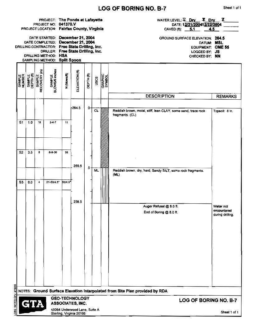
Sheel1 011LOG OF BORING NO. B-7
PROJECT; The Ponds at Lafayette WATER LEVEL: SI- Dry ,J. D~ -1.'----__ PROJECT NO: 041370.V CATE: 12/21/20041212212004 ===
PROJECT LOCATION: FaIrfax County, VIrginia CAVED (ft): 5.1 4.5
DATE STARTED: December 21,2004 GROUND SURFACE ELEVATION: 264.5 DATE COMPLETED: December 21, 2004 DATUM: MSl
DRILLING CONTRACTOR: Free State Drilling, Inc. EaUIPMENT: CME 55 DRILLER: Free State Drilling, Inc. LOGGED BY: JS
DRILLING METI-iOD: HSA CHECKED BY: NN SAMPLING METHOD: Spilt SDOan
~~ w" w> ~
z ~~ q ~~
~
~i €€ ~g
~w
.~ I ~ t w ~ ~> "wz ~i'l ~f z w 0
~ ~,
~~ ~ ~ w "'''' m DESCRIPTION REMARKS
264.5 0 CL Reddish brown, moilt, stiff. lean CLAY, some sand, trace rock Topsoil: 8 in.
fragments. (CL)
51 10 2.04·7" "
52 3.5 6-~30• " 259.5
5 ML Reddish brown, dry, hard, Sandy SILT, some rock fragments.
(ML)
53 6.0 4 21-5014.5" 014.5
256.5 Jill Auger Refusal @ 8,0 ft Wst8r nol
encounteredEnd of Boring @ 8.0 ft. during drilling.
~ ~ p Surfac. EI.v.tlon Interpol.ted from Site Plen provided by RDA
g GEO-TECHNOlOGY LOG OF BORING NO. B-7 ~ 'ASSOCIATES, INC. ll: 45064 Underwood Lane, SLllte A
Sheel1 of 1 Sterling, Virginia 20166 9

53
Sheel1 of 1LOG OF BORING NO. B-8
PROJECT: PROJECT NO:
PROJECT LOCATION:
DATE STARTED: DATE COMPLETED:
DRILLING CONTRACTOR: DRILLER:
DRIlLING METHOD: SAMPLING METHOD"
~~.IM ~~
~~
S,
S2
gwe w, ~~~~
.~ .~
~~ ~~
10 H
,3.'
6.0 0
•• w~ ~-
~~ ~o ~ ~
2-3-8
50/5.5"
SOIa"
The Ponds at Lafayette 041370.V Fairfax County, VIrginia
December 22. 2004 December 22, 2004 Free State Drilling, Inc. Free State Drilling, Inc. HSA Split Spoon
i € z
~ g
~ ~
~ ~
u~-0 ~~
~~ z w ~ ~~
~ w
261.7 a CH
"
256.7 SM
0/5.5
5
255.7 5010'
I
WATER LEVEL: £. Dry.t: '1-'----__ DATE: 1212212004 ===
CAVED (tI): 2.8
GROUND SURFACE ELEVATION: 261.7 DATUM: MSL
EQUIPMENT: CME 55 LOGGED BY: JS
CHECKED BY: NN
DESCRIPTION I REMARKS
Tannish brown, moist, stiff, fat CLAY, little Band. (CH) Topsoil: 7 in.
Greyish brown, dry. very dense, Silty SAND. some rod! fragments. (8M)
Auger Refusal @6.0 fl. Water not encounteredEnd of Boring @ 6.0 fl. during drilling.
~ ~ NOlES: Ground Surface Elevation interpolated from Site Plan provided by RDA
0 GEO·TECHNOLOGY LOG OF BORING NO. B-8 ASSOCIATES. INC. i~.. 45064 Underwood Lane, Suite A
Sheel 1 of 1 Sterling, Virginia 20166 "
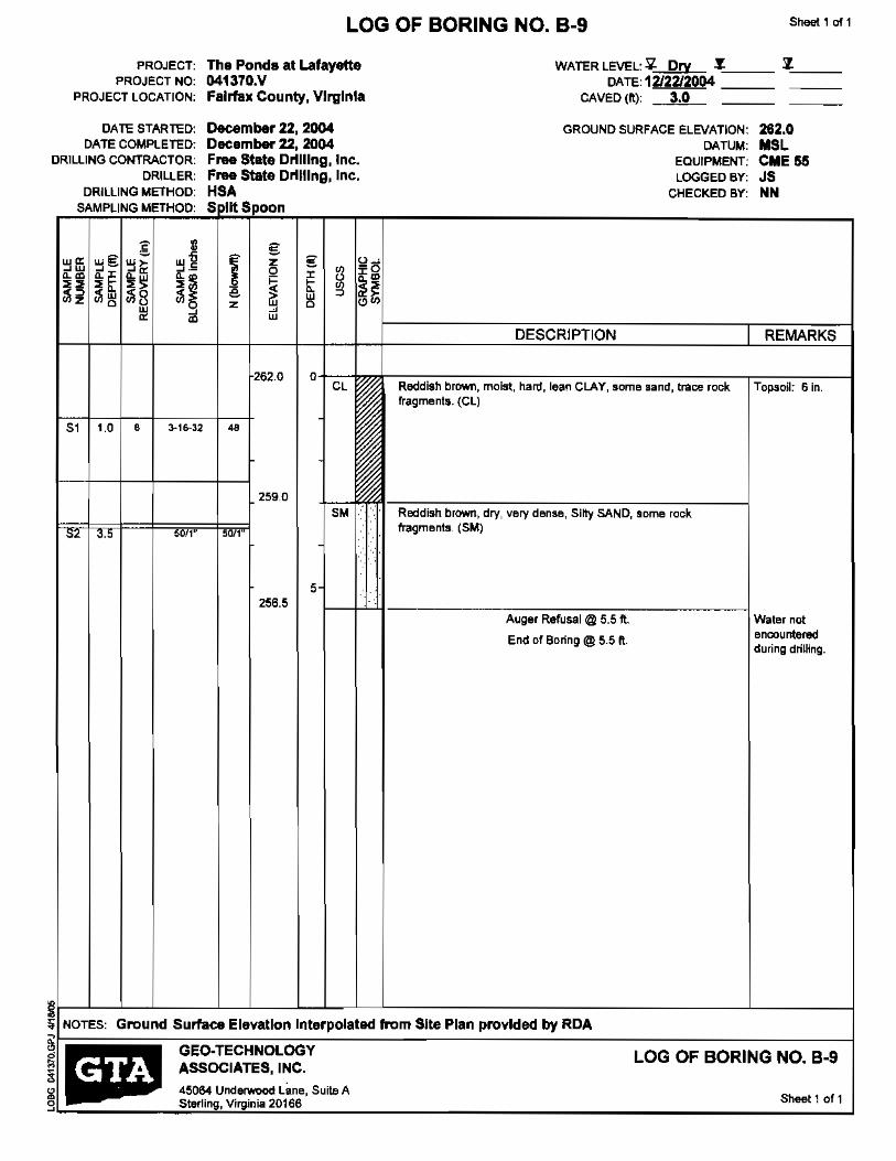
Sheet 1 DI' 1LOG OF BORING NO. B-9
PROJECT: PROJECT NO:
PROJECT LOCATION:
DATE STARTED: DATE COMPLETED:
DRILLING CONTRACTOR: DRILLER:
DRILLING METHOD: SAMPLING METHOD:
w~ .w wi!: ~ ~
w~ .~
•• ~~
~'" ~~ ~~ !;~ ~i! ~~ ~8 ~~ w ~
~ '"
,51 1.0 3-16"32
still"1.2 I '.5
The Ponds at Lafayette WATER LEVEL: ~ DrY.t: 7"----__ 041370.V DATE,1212212004 === Fairfax County, Virginia CAVED (ft.): 3.0
December 22,2004 GROUND SURFACE ELEVATION: 262.0 December 22,2004 DATUM: MSl Free State Drilling, Inc. EQUIPMENT: CME 55 Free State Drilling, Inc. LOGGED BY: JS HSA CHECKED BY: NN S I~Sipoon
u~€ ~ -0
~ u~ ~'" ~
wI €
t ~ ~~ z ~ 0 ~ w
DESCRIPTION I REMARKS
262.0 0 CL Reddish brown, moist, hartl, lean CLAY, some land, crace rock Topsoil: 6 in.
fragments. (eLl
"
259,0
5M Reddish brown, dry, very dense, Silty SAND, some rock fragments, (5M)'M
5 256.5
Auger Refusal @ 5.5 ft. Water not encountered
End of Boring @ 5.5 ft. during drilling.
~ ~ NOTES: Ground Surface Elevation Interpolated from Site Plan provided by RCA
GEO·TECHNOLOGY LOG OF BORING NO. B-9 ASSOCIATES, INC.!m:ar~ 45064 Underwood Lime, Suite A
Sheet 1 of 1Sterling, Virginia 20166"

Sheet 1 of 1 LOG OF BORING NO. B·10
PROJECT: The Ponds at L.afayette WATER LEVEL: 'Q pry ,f.~== 'l"----__PROJECT NO: 041370.V DATE: 12/2212004
PROJECT LOCATION: Fairfax: County, Virginia CAVED (tt): 2.8
DATE STARTED: December 22, 2004 GROUND SURFACE ELEVATION: 281.9 DATE COMPLETED: December 22, 2004 DATUM: MSL
DRILLING CONTRACTOR: Free State Drilling, Inc.. eQUIPMENT: CME 55 DRILLER: Free State Drilling, Inc. LOGGED BY: JS
DRILLING METHOD: HSA CHECKED BY: NN SAMPLING METHOD: S lit Spoon
'2
I €~
w~ u~we: wI z €w~ ~w
~" u ~~ ~- Q 00 ~g
~m ~. ~~ ~~ 00~~ t< "" ~ ~~;1 ~~ ~8 ~o z >w aw ~~
~ ~~ m w
DESCRIPTION I REMARKS
261.9 0 CH Tannish brown, moist medium stiff, fat CLAY, trace 'and. (CH) Topsoil: Bin.
,, .0 13 2~-3S'
258.9 SM Reddish brown, dry, very dense, Silty SAND, some rock
fragments. (5M)S2 3.5 , 50/5" 50/5"
5
255,9
S3 '.0 0 ""0' 5010" Auger Refusal @6,0 ft. Water nol encount1!lnKIEnd of Boring @ 6.0 ft. during drilling.
,
I
~ ~ NOTES: Ground Surface ElevatJon interpolated from Sft. Plan provided by RDA
~IP GEO-TECHNOLOGY LOG OF BORING NO. B·10 ASSOCIATES, INC.
~ " . 45064 Underwood Lane, Suite A
Sheet 1 of 1g Sterling, Virginia 20166

PROJECT: PROJECT NO:
PROJECT LOCATION:
DATE STARTED: DATE COMPLETED:
DRILLING CONTRACTOR: DRILLER:
DRILLING METHOD: SAMPLING METHOD:
<' •• W~ wi§: "j>
~
"W ~~ ~~
.~ "~ "'~h h ;:;8
w ~~ " ~ m
Sheet 1 of 1 LOG OF BORING NO. B-11
The Pond. at Lafayette 041370.V Fairfax County, VIrginia
December 22, 2004 December 22, 2004 Free Swte Drilling, Inc. Free State Drilling, Inc. HSA S lit Spoon
g z g 2 0Q u ~m• ~ tI w '" ~'" ,,~z ~ c
~
w "
266.0 0
WATER LEVEL: ~ Dry .!.'--::== "'~===DATE: 1212212004 _ CAVED (ft): 2.5
GROUND SURFACE ELEVATION: DATUM:
eQUIPMENT: LOGGED BY:
CHECKED BY:
288.0 MSL CME 55 JS NN
DESCRIPTION I REMARKS
ML Reddish brown, moist, hard, Sandy SilT, some rock fragments. Topsoil: 5 in (ML)
51 1.0 " 5-1(1..3-4 '"
.. .
5
260.0 53 6.0 0 5010" 5010" Auger [email protected]. Water nol
end of [email protected]. encountered during driUing.
,
• ~
NOTES: Ground Surface Elevation interpolated from Site Plan provided by RDA
GEO-TECHNOLOGY LOG OF BORING NO. B-ll ASSOCIATES, INC.
45064 Underwood Lane, SUite A Sheel1 of 1if. Sterling, Virginia 20166
i
9
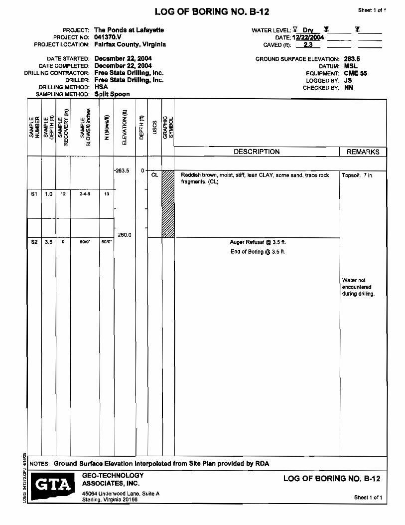
Sheet 1 at 1LOG OF BORING NO. B-12
PROJECT: The Ponds at Lafayette WATER LEVEL: ~ Dry .J.,--:=== '1:'----__ PROJECT NO: 041370.V DATE: 1212212004 _
PROJECT LOCATION: fairfax County, VirginIa CAVED (ft): 2.3
DATE STARTED: Decsmber 22, 2004 GROUND SURFACE ELEVAllON: 283.5 DATE COMPLETED: December 22,2004 CAruM: MSL
DRILLING CONTRACTOR: Free State Drilling, Inc. EQUIPMeNT: CME 55 DRILLER: Free State Drilling, Inc. LOGGED BY: JS
DRILLING METHOD: HSA CHECKED BY: NN SAMPLING METHOD: S lit Spoon
g~ wO: z g ~w
~g ~~ ~~ ~ ~B ~o: I
~m I ~ m~~ ~ ~ ~ ~~~~ ~e ~ w ~ ~~~~ h ~8 ~~ ~~0 z 0w• ~
~ wm DESCRIPTION I REMARKS
263.5 0 CL Reddish brown, moist. stiff, lean CLAY, some sand, Irace rock Topsoil: 7 in,
fragments. (el)
51 1.0 ,-<-," "
260.0 ,5' " 5010" 5010" Auger Refusal@ 3.5 ft.
End of Boring@ 3.5 ft,
Water not encountered during drilling.
~ ~IGround Surface Elevation Intarpolated from Sita Plan provldad by RCA
~ ~ GEO·TECHNOLOGY LOG OF BORING NO. B-12 " I ~.' ASSOCIATES, INC. ~ 45064 Underwood Lane. Suite A
Sheet 1 of 1g Sterling, Virginia 20166

Sheet 1 of 1 LOG OF BORING NO. B-13
PROJECT: The Ponds at Laf.y8Ue WATER lEVEL: ~ Dry ,J. 1.8 ~'--:==::: PROJECT NO: 041370.V DATE' 12121120041212212004 _
PROJECT LOCATION:
CATE STARTED: CATE COMPLETED;
DRILLING CONTRACTOR: DRIL.LER:
DRILLING METHOD: SAMPLING METHOD'
;[ •w~ wi? ~w ~- ~> ~F ~m
~~ ~~~~ ~~
~~ ~~ ~~ ~8 ~o
w ~ ~ m
51 1.0 ,. 6-22-31
52 3.5 , 50/-4.5"
53 6.0 0 5010"
Fairfax County, VIrginia
December 21, 2004 December 21, 2004 Free Stale Drilling, Inc. Free Stale Drilling, Inc. HSA Spill Spoon
f E z0 E
Z ~ u~-0Zm
! z ~
~ ~
~ 00 ~
~~ ~> 0 00
~ w
264.0 0 CL
53
261.0 5M
OIH
5
258.0 5010'
CAVED (1'1): 3.3 3.3
GROUND SURFACE ELEVATION: 264.0 DATUM: MSL
EQUIPMENT: CME 66 LOGGED BY: JS
CHECKED BY: NN
DESCRIPTION I REMARKS
Reddish brown, moist, hard, lean CLAY, 50me sind, trace rock Topsoil: 6 in. fragments. (ell
'" Reddillt> brown, dry, very deflse, Si!ty SAND, some roCk fragments. (5M)
Auger [email protected]. Water not encounl&redEnd of [email protected]. during drilling.
I
NOTES: Ground Surfaee Elavatlon Interpolated from Site Plan provided by RCA
GEO-TECHNOLOGY . LOG OF BORING NO. B-13 ASSOCIATES, INC.
45064 Underwood Lane, Suite A Sneet 1 of 1 Sterling, Virginia 20166

Sheet 1 of 1 LOG OF BORING NO. B·14
PROJECT: PROJECT NO:
PROJECT LOCATION:
DATE STARTED: DATE COMPLETED:
DRILLING CONTRACTOR: DRILLER:
ORILlING METHOD: SAMPLING METHOD'
v w~ wi? w," l ~w ~.:=~~~-.m .,
!i~~~ ~~ ~~ ~fu ;;;8 ~o0 ~~ m
" ,...~" 1.0
.2 3.5 2-2·~"
.3 6.0 3-5-12"
, 5OI(l"54 8.5
The Ponds at Lafayette 041370.V Fairfax County, Virginia
December 21, 2004 December 21, 2004 Free State Drilling, Inc. Free State Drllllng,lnc. HSA Split Spoon
Ig
" ,,~z g, ~Q ~g
~ ~ ~ e •w ~ ~~
0 o~z ~ w
267.0 0 CL
•
264.0 CH
•
5
"
258.5 SOlO·
WATER lEVEl:.2. Dry .!- Dry ~
DATE' 12121/20041212212004 '=== CAVED (ft): 7.8 7.2
GROUND SURFACE ELEVATION: 287.0 DATUM: MSl
EQUIPMENT: CME 55 lOGGEO BY: JS
CHECKEO BY: NN
DESCRIPTION I REMARKS
Reddish brown, moist, stiff, lean CLAY, 50me sand, trace rock Topsoil: 7 in. fnIgmenle. (ell
Tannish brown, moist, medium stiff, tat CLAY, some sand. trace rock fragmBnm. (CH)
I
---, gray, stiff
Auger Refusal @ 8.5 ft. Water !'tot encounteredEnd of Bol1ng @ 8.5 fl. during drilling.
~ ;j NOTES: Ground Surfaca Elevation Interpolated from Site Plan provided by RDA
• GEO-TECHNOLOGY§p LOG OF BORING NO. B-14 ASSOCIATES. INC.
~ , 45064 Underwood Lane, Suite A
Sheet 1 of 1 Sterling, Virginia 20166 9

Sheet 1 of 1LOG OF BORING NO. B-15
PROJECT: PROJECT NO:
PROJECT LOCATION:
DATE STARTED: DATE COMPLETED:
DRILLING CONTRACTOR: DRILLER:
DRILLING METHOD: SAMPLING METHOD:
g .0: wE .~.w ~~
~;: ..
~~U ~~ <~ ~z ~~ ~~ ~~ •m
,51 1.0 3-2-:Z
,., , 4-5015"5'
53 6.0 0 Mia'
The Ponds at Lafayette WATER LEVEL:.:!l DrY .f. 1.3 'l.'----__ 041370.V DATE, 12121/20041212212004 _ FaIrfax County, Virginia CAVED (ft.): 5.0 1.3
December 21, 2004 GROUND SURFACE ElEVATION: 265.0 December 21, 2004 CAnJM: MSL Free St8te Drilling, Inc. eQUIPMENT: CME 55 Free Stats Drilling, Inc. LOGGED BY: JS HSA CHECKED BY: NN Split 8DOon
g ~ Z g !,2i5
Q ;: l'l ~
~mI ~" w•
~ ~~~ w O~2 W 0
DESCRIPTION I REMARKS
265,0 0 CL Reddish brown, moist, son, lean CLAY, some sand, trece rock Topsoil: e in,
fragments. (ell
• ~
262.0 5M Reddish brown, dry, dense, Silty SAND, some rock fragments.
(8M)50/5"
I , 259.0
"".. Auger Refusal @ 6.0 fl.. Water nol encounteredEnd of [email protected].. during drilling.
~ NarES: Ground Surfece Elevation Interpolated from Site Plan prOVided by RDA§P GEO-TECHNOLOGY LOG OF BORING NO. B-15
'i:! & ASSOCIATES. INC.
~ 45064 UndelWOod lane, Suite A Sheet 1 of 1
...J Sterling, Virginia 20166
i
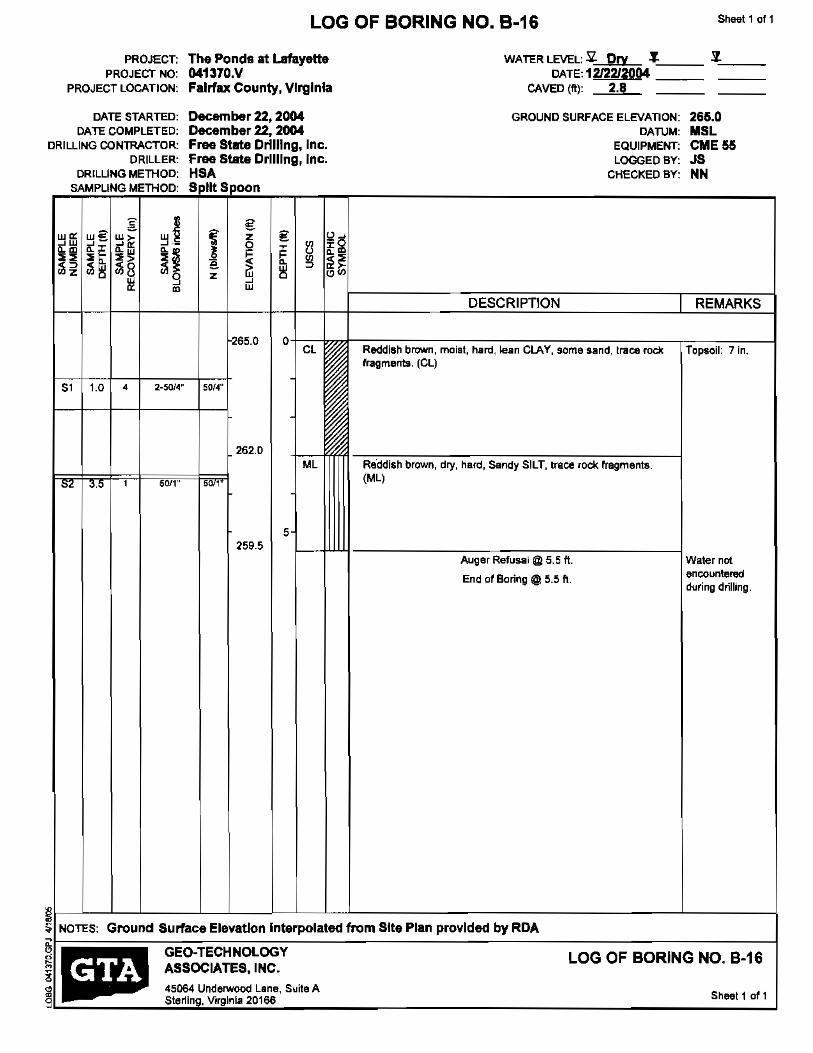
PROJECT: PROJECT NO:
PROJECT LOCATION:
DATE STARTED: DATE COMPLETED:
DRILLING CONTRACTOR: DRILLER:
DRILLING METHOD: SAMPLING METHOD'
w~ ~w ~€
;[ w> ~~
w~ ~-
~m ~r
~~ ~I;: ~~ ~~ ~i1 ~~ ~8
w ~o ~
~ m
265.0 0 CL
S, 1.0 2-50W 501~"•
262.0 ML
OL 50/1"'.0 , ,.
5 259.5
I
~
Sheet 1 of 1 LOG OF BORING NO. B-16
The Ponds at Lafayette 041370.V Fairfax County, Virginia
December 22, 2004 December 22,2004 Free State Drtlllng, Inc. Free State Drilling, Inc. HSA Split Spoon
g z g u~
r u 00 ~:ii
~~ 00•I ~ ~ => ~t;z ~ ~ w
WATER LEVEL: sz. Dry,J. .7.'--__
DATU2I2212004 === CAVED (ft): 2.8
GROUND SURFACE ELEVATION: DATUM:
EQUIPMENT: LOGGED BY:
CHECKED BY:
DESCRIPTION
265.0 MSL CME 55 JS NN
REMARKS
Reddish brown, moist, hard, lean CLAY, some sand, trace rocll: Topsoil: 7 in. fragments. (eL)
Reddish brown, dry, hard, Sandy SILT, Irace rock rregments. (ML)
Auger [email protected]. Water not
End 0' Boring @ 5.5 ft. encountered during drilling.
S NOTES: Ground Surface Elevation Interpolated from Site Plan provided by RDA
GEO-TECHNOLOGY LOG OF BORING NO. B-16 ASSOCIATES, INC.
45064 Underwood Lane, Suite A lip Sheel1 of 1 Sterling, Virginia 20166 "

Sheet 1 011LOG OF BORING NO. B-17
PROJECT: The Ponds at Lafayette WATER lEVEL: ~ Dry .1,--:=== :l~==PROJECT NO: 041370.V DATE:1212V20Q4 _
PROJECT LOCATION: Fairfax County, Virginia CAveD (ft): 3.0
DATE STARTED: December 22, 2004 GROUND SURFACE ELEVATION: 267.5 DATE COMPLETED: December 22,2004 DATUM: MSL
DRILLING CONTRACTOR: Fr'1t8 State DrUllng, Inc. EQUIPMENT: CME 55 DRILLER: Free State Drilling. Inc. LOGGED BY: JS
DRILLING MElHOD: MBA CHECKED BY: NN SAMPLING METHOD: spins oon
C' • ~ =
w~ ~g z o. .w ~> ~~ ~ 0
~ 0 -0 ~m ~m~~ ~~
~
~ ~~ ~~ ~ t ~~
I > w ~ ~~ ~~ ~~ ~8 ~g w ,,0z 0w ~ m w•
DESCRIPTION I REMARKS
267.5 0 CL Re<lclish brown, moist, hard, leiln CLAY, some land, trace roell. Topsoil: 7 ill.
fragmenB. (el)
51 1.0 " 10-17-28 "
264.5 Ml Reddish brown, moist, hard, Sandy SILT, some rodl; fragments.
(ML)52 3.5 , 18-5012" 5012"
262.0 5
1111 Auger [email protected]. Water not
encounteredEnd of Boring @ 5.5 ft. during drilling.
~ ~ NOTES: Ground SUrfaC& Elevation Interpolated from Site Plan provided by RDA
GEO-TECHNOLOGY LOG OF BORING NO. B-17 ASSOCIATES. INC.
45064 Underwood Lane, Suite A Sheet 1 of 1 liP Sterling, Virginia 20166
"

Sheet 1 of 1LOG OF BORING NO. B-18
PROJECT: The Ponds at Lafayette WATER LEVEL::'jZ Dry ~ :1-,-=:==PROJECT NO: 041370.V
DATE: 1212212004 === _PROJECT LOCATION: Fairfax County, Virginia CAVED (ftl: 3.0
DATE STARTED: DKember 22. 2004 GROUND SURFACE ELEVATION: 270.5 DATE COMPLETED: December U. 2004 DATUM: MSl
DRILLING CONTRACTOR: Free Stat, Drilling, Inc. eQUIPMENT: CME 55 DRILLER: Free State Drilling, Inc. LOGGeD BY: JS
DRILLING METHOD: HSA CHECKED BY: NN SAMPLING METHOD: Spilt Sooon
g •• €w", w~~g ~~ € ~~ ~w ~~ ~z ~"' ~ z 13•• ·t ~~ ~~ I ~ t ~ ~~<w w~~ ~o ~~ ~o z w 0 ~0
~ w ~
~
DESCRIPTION I REMARKS
270.5 0 CL Grayish brown, moist, very stitt', lean CLAY. some sand, trsce Topsoil: 6 in.
rock fragments. (CL)
51 1.0 7·6-10 , " "
267.5 ML Reddi$h brown, moist, hard, Sandy SILT, trace [oci( fragments.
52 '.5 • 39-50/5.5" 015,5 (Ml)
5
I I 264.5
5' 6.0 0 SOlO" 5010' Auger Refuaal @6.0ft. Water nol encounteredEnd of Boring @6.0 rt. during drilling.
~ !i NOTES: Ground Surface Elevation Interpolated from Site Plan provided by RCA
~p GEO-TECHNOlOGY LOG OF BORING NO. B-18 ~ • ASSOCIATES, INC.
o 45064 Underwood lane, Suite A Sheet 1 of iSterling, Virgini8 20166 9
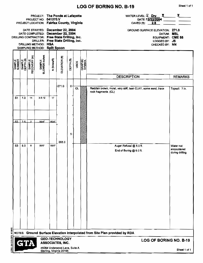
PR.OJECT: PROJECT NO:
PROJECT LOCATION:
DATE STARTED: DATE COMPLETED:
DRILLING CONTRACTOR: DRILLER:
DR.ILlING METHOD: SAMPLING METHOD:
:§: ~~ w€ ">
~~ ~.-"~ • ill .~~~ ~i~~ ~i'i ~8 00 0 ~
~ ~ "
Sl 1.0 14 3-5-12 "
5
1---1---+--I_--+----+ 265.0 50/{)" 5WO"
LOG OF BORING NO. B-19
The Ponds at lafayette 041370.V Fairfax County, Vlrglnle
December 22, 2004 December 22, 2004 F.... State Drilling, Inc. Frue State Drilling, Inc. HSA S lit Snoon
E I.
Z~ Q ,E ~gl ~! \< 0> • ~ ~~
z i'i 000
" ~ "
271.0 0 CL
WATER LEVEL:.sz. Pry y.DATE: 12f2212004
CAVED ('1 2.B
GROUND SURFACE ELEVATION: DATUM:
EQUIPMENT: LOGGED BY:
CHECKED BY:
DESCRIPTION I
Reddiah brown, moist, very sliff, lean CLAY, some sand, trace rock fragments. (Cll
Auger Refusal@ 6.0 fl.
End of Boring @ 6.0 fI
Sheet 1 of 1
~'-::== _
271.0 MSL eME 55 JS NN
REMARKS
Topsoil: 7 in.
Waler not encountered during drtlling.
LOG OF BORING NO. B-19
Sheet 1 of 1

PROJECT: PROJECT NO:
PROJECT LOCATION:
DATE STARTED: DATE COMPLETED:
DRILLING CONTRACTOR; DRILLER:
DRILLING METHOD: SAMPLING METHOD:
§:w"' WE ~.~~~ §~ <;:
.~ ~~ ~~ ~~ ~~
m"' ~
Sheet 1 of 1LOG OF BORING NO. B·20
The Pond. at l.8flJyett& 041370.V Fairfax County. Virginia
December 22, 2004 December 22, 2004 Free Sta.. Drflllng, Inc. Free State Drilling, Inc. HSA Spilt SDOon
€ ~~~ z €
~ ~1 z
~
~ n o~z ~ ~
iii
268.0 0
WATER LEVEL: ~ Drv.Y. ~=== DATE: 1212212004 -=== CAVED (ft): 2.8 _
GROUNO SURFACE ELEVATION: CAruM:
EQUIPMENT: LOGGED BY:
CHECKED BY:
268.0 MSl CME 55 JS NN
DESCRIPTION I REMARKS
CL Reddish brown, moist, hard, lean CLAY, some sand, trace rock /mfld- 1 • fragments. (el)
51 1.0 " 1<).8-5013" 50/3"
8' ,., , 50/0,5" 0(0,5'
5 262.5
Auger Refusal @ 5.5 ft. Waler nOt
End of Boring @ 5.5 fl. encountered during drilling.
• ~ ';j NOTES: Ground Surface Elevation Interpolated from Site Plan provided by RDA
!I"GEO-TECHNOLOGY lOG OF BORING NO. B·20ASSOCIATES, INC.
45064 UnderwoOd Lane, Suite A Sneet 1 of 1 Sterling, Virginia 20166 9

Sl'leal 1 011 LOG OF BORING NO. B-21
PROJECT: PROJECT NO:
PROJECT LOCATION:
DATE STARTED: DATE COMPLETED:
DRILLING CONTRACTOR: DRILLER:
DRILLING METHOD: SAMPLING METHOD:
.. ~
•• w~ ~g w~ w~ ~w ~~ ~.-
"~
~~ ~~ <~ oo~
~~ ;:;g w
~~ ;:;0 ~
~ ~
81 1.0 , 10-5014"
82 3.5 1 SOIO,5"
The Ponds at lafayette WATER LEVEL: 5l Dry.l. .1-'-__ 041370.V DATE: 1212212004 === Felrfax County, Virginia CAVED (II): 2.0
December 22,2004 GROUND SURFACE ELEVATION: 285.5 December 22, 2004 DATUM: MSl Free State Drilling, Inc. EQUIPMENT: CME 55 Free State Drllllng, Inc. LOGGED BY: JS HSA CHECKED BY: NN S litSnnon
z € € !Jg000 , I ~ ill ~~
e w ~ ~~" ~ooz 0 ~ w
DESCRIPTION i REMARKS
2655 0 CL Reddish brown, moist, hard,lean CLAy, some sand, Iraoe rock Topsoil: 7 in.
fragments. (ell
5llI'4"
262.5 8M Reddish brown, dry, very dense, Silty SAND, some rock
fragments. (5M)0105'
, 260.0
Auger Refusal@ 5.5 ft, Wstetnol ftncounteredEnd af BOrlng@ 5,5 ft. during drilling.
~ ~ NOTES: Ground Surface Elevation interpolated from SIte Plan provided by RDA
~ GEO-TECHNOLOGY LOG OF BORING NO. B-21 ASSOCIATES, INC.
4!r064 UndelWood lane, Suite A Sheet 1 of 1 liP Sterling, Virginia 20166
~

Sheel1 or 1 LOG OF BORING NO. P-i
PROJECT: The Ponde at Lafayette WATER. LEVEL::!l Dry:t. 7-'--__ PROJECT NO: 041370.V DATE: 1212212OO4 _
PROJECT lOCATION: Fairfax County, Virginia CAVED 1ft) 1.8
DATE STARTED: December 22, 2004 GROUND SURFACE ELEVATION: 263.0 DATE COMPLETED: December 22, 2004 CATUM: MSl
DRILLING CONTRACTOR: Free Stlte Drilling, Inc. EQUIPMENT: CME 55 DRilLER: Free Stete Drilling, Inc. lOGGED BY: Js
DRilLING METHOD: HSA CHECKED BY: NN SAMPLING METHOD: S lit Spoon
I z
DESCRIPTION I REMARKS
263.0 o CL Reddish brown, moist, very aliff, lean CLAY, SOme sand, trace Topsoil: 7 in.
rock fragments. (Cl)
51 1.0 1~ 3-6-16
260.0
8M Reddish brown, dry, \/ery dense, Silty SAND, some rock fragments. (SM) 52 3.5 1 5010.5" 010.5
258.0 ';+--+-''-'1 ------;:--;-;=--===-----1End of [email protected].
Water not am;;ountered during drilling
lif----l--.---l---L_---L-L-----L.-L-l-l -'-__-I ~ NOTES: Ground Surface Elevation interpolated from Site Plan provided by RDA
GEO-TECHNOLOGY LOG OF BORING NO. P-lASSOCIATES, INC.
45064 UndelWOod lane, Suite A Sheet 1 of 1S\eJling, Virginia 20156

Sheet 1 of 1LOG OF BORING NO. P-2
PROJECT: The Ponds at Lafayette WATER LEVEL: '].. Dry .t:'"-=== 7-,"-===
PROJECT NO: 041370.V OATE;1~2212~ __ __ PROJECT LOCATION: Fairfax County, Virginia CAVED (It): 2.0
DATE STARTED: December 22, 2004 GROUND SURFACE ELEVATION; 272.0 DATE COMPLETED: December 22, 2004 DATUM: MSl
DRfLUNG CONTRACTOR: Free State Drf"'ng, Inc. EQUIPMENT: CME 55 DRILLER: Free Sl8te Drilling, Inc. LOGGED BY; JS
DRILLING METHOD: HSA CHECKED BY; NN SAMPLING METHOD: S IItSpoon
'2 U gW'" w~ "J>
~
w~ Z g ~w ~- ~- ~ x Oom x u .. m.. '" f ,,~
~~ g,~ ,,~ ~~ !< t 3 ~~ ;J;~ ;Ji~ ;JiS ;Jio ~ z ~ "ww ~ ~ wm'" DESCRIPTIDN REMARKS
272.0 0 CL Reddish brown, moist, hard, lean CLAY, some sand, trace rock Topsoil: 7 in.
fragmenta, (ell
9-21-~O51 1.0 " "
269.0 ML Reddish b'own, dry. hard, Sandy SILT, some rock fragments.
S2 35 , 5010.5" 010.5' (M'I Water not encoumeilld durlng drilling.
267.0 5 End of Boring@ 5.0 ft,
~ ~rP Surface Elevation interpolated from Site Plan provided by RCA
0:;
• • GEO·TECHNOLOGY ASSOCIATES, INC.
LOG OF BORING NO. P-2
~ .....
45064 Underwood lane, Suite A Sterling, Vrginia 20166 Sheet 1 of 1
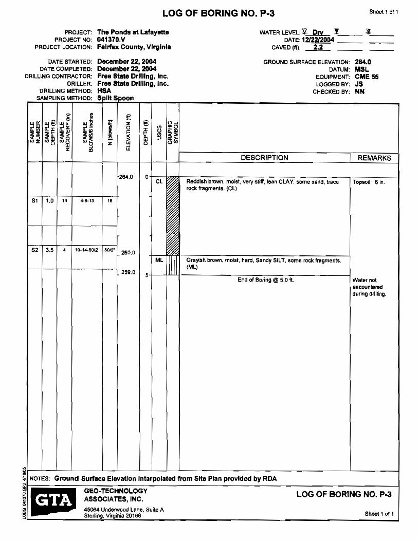
Sheet 1 of 1LOG OF BORING NO. P·3
PROJECT: The Ponds at Lafayette WATER LEVEL: ~ Dry:J. ~~=:: PROJECT NO: 041370.V DATE 1212212004 _
PROJECT LOCATION: FalrfllX County, Virginia CAVED (ft): 2.2
DATE STARTED: December 22, 2004 GROUND SURFACE ELEVATION: 264.0 DATE COMPLETED; December 22, 2004 DATUM: MSl
DRILLING CONTRACTOR: Free State DrllUng, Inc. EQUIPMENT: CME 56 DRILLER: Free State Drilling, Inc. LOGGED BY: JS
DRILLING METHOO: HSA CHECKED BY: NN SAMPLING METHOD: S lit Saoon
-c ~ €w€ z €~ffi ~1'i ~~ o~
~m ~w» >. »
~
t ~~" ~~g
~~ e w ~ ~~ ~>! ~~ ~8 00 z ~ 0w ~ ~
m I w "'" " DESCRIPTION I REMARKS
264.0 0 Cl Reddish brown, moi,t, very still', lean CLAY, some sand, trace Topsoil: 6 in.
rocK fragments. (eLl
51 1.0 4-6-13" "
52 3.' 19-14-5012" 50/2'• 260.0 Ml GrayiSh brown, moist, hard, Sandy SILT, some rock fragments.
• (ML)
259.0 End of Boring@ 5.0 ft. Water not
encountered tluring drilling.
~ ~ NOTES: Ground Surface ElevatIon Intarpalated from Site Plan provided by ROA ,
GEO-TECHNOLOGY LOG OF BORING NO. P-3 ASSOCIATES, INC.
45064 un~~~d lane, Suite A Sheet 1 of 1III!! Sterling, Vi inia 20160 ~

Sheel 1 of 1 LOG OF BORING NO. P-4
PROJECT: The Ponds at Lefayette PROJECT NO: 041370.V
PROJECT LOCATION: Fairfax County, Virginia
DATE STARTED: December 21, 2004 DATE COMPLETED: December 21, 2004
DRILLING CONTRACTOR: Free State Drilling, Inc. DRILLER: Free State Drilling, Inc.
DRIUING METHOD: HSA SAMPLING METHOD: SplRSpoon
~
w~ w£: ~>
'2
~I ~ g z g
~ f:'! 31~w I
~m ~~ m ~~ ! ~ i>l ~~~~
~~~ ~~ ~ w ~>~§ ~ ~ooz 0 ~ ~ '"~ '"0 w
~
~ m
I 265.6 0 CL
51 1.0 S·13-31 ~"
52 32·50f5.5" 015.5'3.' •
260.6 5
I
WATER LEVEl.:.2. Dry .!. Dry '.1- _ DATE 12121120041212212004 _
CAVED (II): 3.3 3.1
GROUND SURFACE ELEVATiON: 265.6 DATUM: MSL
EQUIPMENT: CME 55 LOGGED BY: JS
CHECKED BY: NN
DESCRIPTION I REMARKS
Reddish brown, moist, herd, lean CLAY, some sand, trace rock Topsoil: 6 in. fragments. (Cl)
End Df Boring@ 5.0 ft. Water net encounMrod during drilling.
,
~ NOTES: Ground Surface Elevation Interpolated from Site Plan provided by RCA
GEO-TECHNOLOGY LOG OF BORING NO. P4,• . ASSOCIATES, INC.
45064 UnclelWoocllane, Suite A "ltD Sheel1 of 1Sterling, Virginia 20166 "
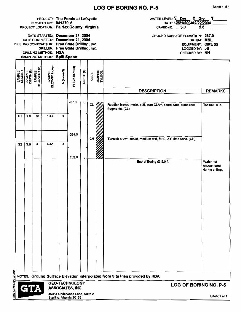
PROJECT: PROJECT NO:
PROJECT LOCATION:
DATE STARTED: DATE COMPLETED:
DRILLING CONTRACTOR: DR.ILLER:
DRILLING METHOD:
SAMPLING METHOD:
w~
gw§: W~ w~
~w ~m ~~ ~~ ~.-
~~ ~. ~~ ~~ <Ji~ ~~ ~o
~ '"
S1 1.0 12
S2 3.5 8
l---+-+--+---t---+ 262.0 5
Sheet 1 of 1 LOG OF BORING NO. P·5
The Ponds at Lafayette 041370.V Fairfax County, Virginia
December 21, 2004 December 21, 2004 Free State Drilling, Inc. Free St.te Drilling, Inc. HSA S It Spoon
g Z g~ ~1i
~ ~mS ~1 w ~ ~~ z ~ 0 ,,
~ w
267.0 0
,
264.0
,
WATER. LEVEL: £. Dry .I Dry ~'--::== DATE, 12/21/200412/22/2004 _
CAVED (fl.): 3.0 2.8
GROUND SURFACE ELEVATION:
DATUM: EQUIPMENT: LOGGED BY:
CHECKED BY:
DESCRIPTION
267.0 MaL CME 55 JS NN
REMARKS
ReddJah brown, mo~t, IIUff, lean CLAY, some sand, trace roc« Topsoil: e in. fragments. (Cl)
Tannish brown, moist, medium stiff, fat CLAY. little sand. (CH)
End of Boring @ 5.0 ft. Water nol encountered during drilling.
i NOTES: Ground Surface Elevation Interpolated from Sit. ptan provided by RDA
~/-;::===~-=G-=Eo-=TE:::C:;H::-NO=LO:::G:::Y~------~--~----L-O-G-O-F-B-O-R-I-N-G-N-O-.-P-.-S---l ~ ASSOCIArES, INC. " 45064 Underwood Lane, Suite A 9L..:: -"s:::,.:::''':::'''''...:V:::''',,':::,':..::'':.:'.::''::..... s_...._'_'_"_'...J

Sheet 1 of 1LOG OF BORING NO. P-6
PROJECT: The Ponds at lafayette WATER LEVEL: ¥. Dry .s: Dry Z,--::==PROJECT NO: 041370.V DATE' 121211200412122/2004 _
PROJECl LOCATION: Fairfax. County, Virginia CAveD (fl.): 4.0 3.6
DATE STARTED: December 21, 2004 GROUND SURFACE ELEVAl1ON: 264.0 DATE COMPLETED: December 21, 2004 DA'T\JM: MSL
ORILLING CONTRACTOR: Free state Drilling, Inc. EQUIPMENT: CME 55 DRILLER: Free State Dnlllng, Inc. LOGGED BY: JS
DRILLING METHOD: HSA CHECKED BY: NN SAMPLING METHOD: S lit Snoon
g • g w« ~g w~ w~ z g !,26~w ~« ~ .-
Z w zm~m ~z Ii~~ ~ ~2~~~ ~!5 ,,~Q U ~o I ~ ~Z ~~ m
~ w
DESCRIPTION I REMARKS
254.0 o Cl Reddish brown, moist. soft., lean CLAY, some sand, trace ro<x Topsoil: 71n.
fragments. (ell
51 1.0 1 2-1-2 ,
I Ml Grayish brown, moist, hard, Sandy SILT, little rock fragments. (FlAL)S2 3,5 15 9-15-23
1-----1--+---+-----\--+ 259.0 s-l---\llllj -----:o-'7'"-;::-c-c~_:___---_____j End of [email protected]. Water not
encolJntered dUring drilling.
~!I--l-l---'-------L---L-l-L-L--L------------...l--------1 ;a: NOTES: Ground Surface Elevation Interpolated from Site Plan provided by RDA
~I. GEO~ECHNOLOGY LOG OF BORING NO. p~ ~~ • ASSOCIATES, INC. v
...J
45064 Underwood Lane, Suite A Sterling. Virginia 20166 Sheet 1 of 1

Sheet 1 Of 1LOG OF BORING NO. P-7
PROJECT: The Ponds at Lafayette WATER LEVEL: '!l Dry .1.,--:=== 'l,--:===PROJECT NO: 0413TO.V DATE: 1212212004 _ _
PROJECT LOCATION: Fairfax County, Virginia CAVED (Il): 2.4
DATE STARTED: December 22, 2004 GROUND SURFACE ELEVATION: 263.5 DATE COMPLETED: December 22. 2004 OATUM: MSl
DRILLING CONTRACTOR: Free State Drilling, Inc. EQUIPMENT; CME 55 DRILLER: Free Stem DtUllng, Inc. LOGGED BY: JS
DRILLING METHOD: HSA CHECKED By: NN SAMPLING ME11-IOD: Split Spoon
,,~WOO wg Z g~I ~~
:g ~I ~
g ~ -0
~~ g I~ ~~ ~~ ~ ~ ill e W ~:Ji;;? !~ :Jig !~ Z ~ 0
~> o~
W
• ~
~ oo • DESCRIPTION REMARKS
263.5 0 ML Reddish brown, moist, hard, Sandy SILT, little rock fragments. Topsoil: 7 in.
I (ML)
51 1.0 , 9·Z1-SG/2" son"
,IS> I 3.' 50 l' 50/1"
1II11258,5 , End of [email protected]. Water riot
encountered during drilling.
~ ;; NOTES: Ground Surface Elevation Interpolated from Site Plan provided by ROA
GEO-TECHNOLOGY LOG OF BORING NO. P-7 ASSOCIATES, INC.
45064 Underwood lane, Suite A !IP Sheet 1 of 1 Sterling, Virginia 20166 9
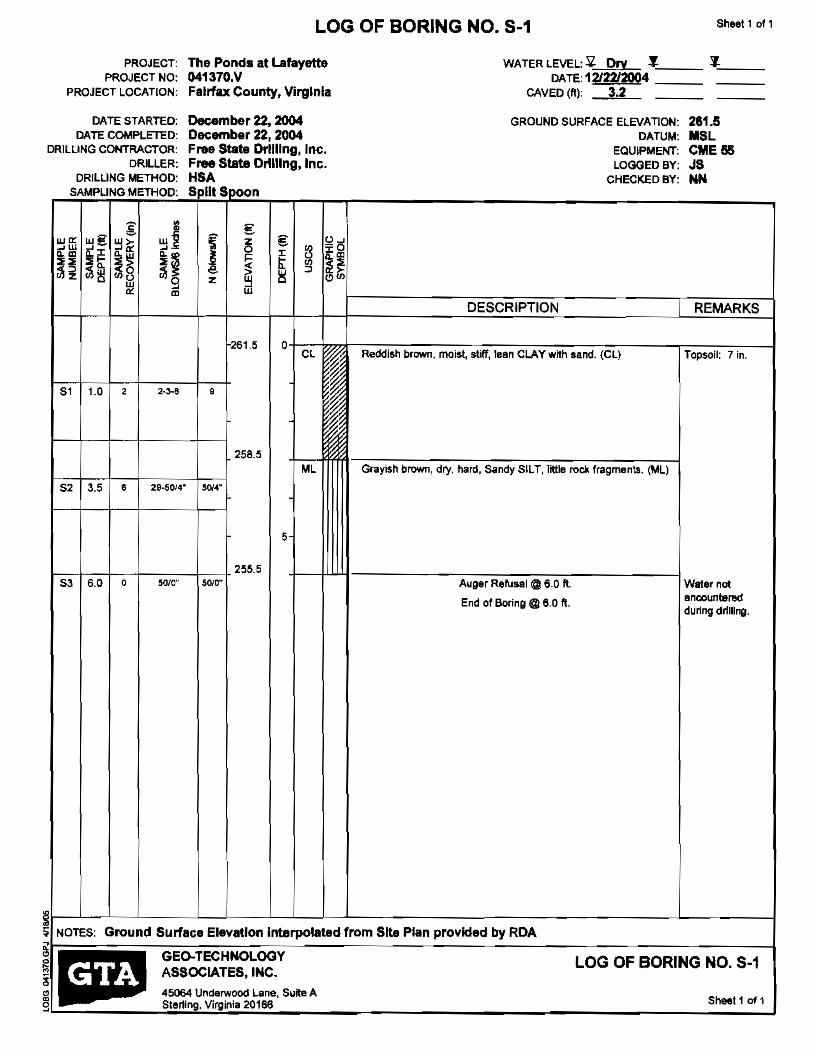
Sheet 1 011LOG OF BORING NO. 5-1
PROJECT: The Ponds at Lafayett& WATER LEVEL: 5l Dry :1.'-=== ~"===
PROJECT NO: 041370.V DATE:1212212004 _ _ PROJECT LOCATION:
DATE STARTED; DATE COMPLETED:
DRIlliNG CONTRACTOR: DRILLER:
DRIlliNG METHOO: SAMPLING METHOD;
m ~ wg '" w~
~w ~I ~~ ~~ ~~U ~~ ~~
~~ ~~ ~8w ~9 ~ m
51 1.0 , 2-3-6
51 3.5 29-5014'•
53 6.0 0 SOlO"
F.lrfax County, Virginia
December 22, 2004 December 22, 2004 Free State Drilling, Inc. Free State Ol1l11ng, Inc. HSA Spill S~on
g u~[ -0
! z0
g II ~ m~ ~ e ~ 0 ~~
z ~ o~
261.5 0 Cl~
~ , ~ ~
f ~ ~
258.s Ml
SllI4"
5
255.5 SOJO"
CAVED (ft): 3.2
GROUND SURFACE ELEVATION: DATUM:
EQUIPMENT: LOGGED BY:
CHECKED BY:
DESCRIPTION
Reddish brown. moist, stiff, lean CLAY with sand. {ell
Gfaylsh brown, dry, hard, Sandy SILT, little rock fragments. (ML)
Auger Refusal @6.0 ft.
End of Boring@6,0 ft.
I
281.5 MSl CME 55 JS NN
REMARKS
Topsoil: 7 in.
Water not ancounterBd during: drilling.
~ ~ NOTES: Ground Surface Elevation Interpolated from Site Plan provtded by RDA§. GEO-TECHNOLOGY LOG OF BORING NO. 5-1 !'! • ASSOCIATES. INC.
~ 45064 Underwood Lane, Suite A Sterling, Virpinia 20166 Sheet 1 0' 1
I
I
9
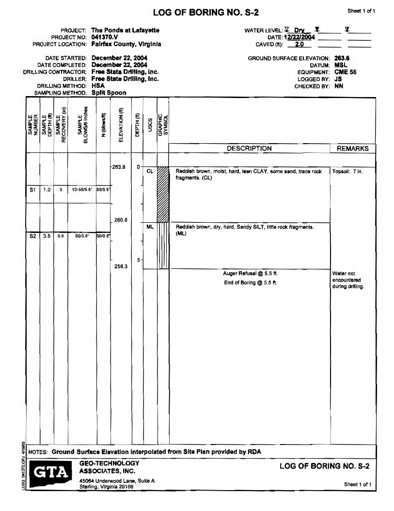
Sheet 1 of 1LOG OF BORING NO. 8-2
PROJECT: The Pond. at Lafayette WATER LEVEL: ~ Dry .!.~== 'l~__PROJECT NO: 041370.V DATE: 12J2212OO4
PROJECT LOCATION: FaIrfax County, Virginia CAVED (tl): 2.0
DATE STARTED: December 22, 2004 GROUND SURFACE ELEVATION: 283•• DATE COMPLETED: December 22, 2004 CAlUM: MSl
DRILLING CONTRACTOR: Free Stata Drilling, Inc. EQUIPMENT: CME 56 DRILLER: Free State Drilling, Inc. LOGGED BY: JS
DRILLING METHOD: HSA CHECKED BY: NN SAMPLING METHOD: SpIII S;poon
•g €w€ w~ z € u.
~ffi ~~ ..- ~ -0Q ,,~."H ~"~~ ~~ ~~ I e "t ~ ~~ ~~ ~8 ~o z ~ ~ ~'" w ~" ~ • •w
~
~
DESCRIPTION I REMARKS
263.8 0 CL Recldlsh brown, moist, hard, lelln CLAY, some sand, trace rock TOP50il: Tin.
fragments. (eL)
51 1.0 , 11J_50/5,5" 015.5'
260.6 ML Redaish brown, dry, hard, Sandy SILT, little rode. fragments.
(ML)52 35 0.' S(lIO,S" 010,5
5 II1I Auger Refusal @ 5.5 ft. Water not
encountered
258.3
End of Boring @ 5.5 ft. during drilling.
~ ;;;: NOTES: Ground Surface Elevation Interpolated rrom Site Plan provided by RDA
GEO·TECHNOLOGY LOG OF BORING NO. 5-2 ASSOCIATES. INC. ;p 45064 Underwood lane, Sutte A
Sheet' of 1 Sterling, Virginia 20166"
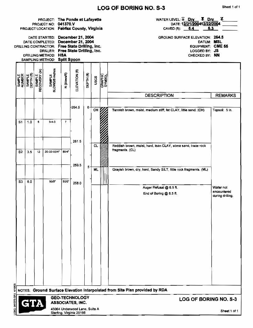
Sheet 1 of 1LOG OF BORING NO. 5-3
PROJECT: The Ponds st Lafayette WATER LEVEL: ~ Dry ,J Dry .1."----__ PROJECT NO: 041370.V DATE,12121!2!!041212212004 ===
PROJECT LOCATION: Fairfax County, Virginia CAVED (ttl: 5.4 5.3
DATE STARTED: Deeember21,2004 GROUND SURFACE ELEVATION: 264.5 DATE COMPLETED: December 21,2004 DATUM: MSL
DRILUNG CONTRACTOR: Free Stale Drilling, Ine. EQUIPMENT: CME 55 DRILLER: Free State Drilling, Ine. LOGGED BY: JS
DRILLING METHOD: HSA CHECKED BY: NN SAMPLING METHOD: SDllt SDoon
g •• g w~ wE w> z g u~~~ ~ -0~w Q I~i'l"~ ~~ ~ ",;~~ ~ ~ ~o ~~ e w ~>~~ ;:;~ ~u ~o
•z ~ ·0
~
~
~
"'~ ~ ~ w
DESCRIPTION I REMARKS
264.5 o CH Tannish brown, moist, medium stiff, fat CLAY, little sand. (CH) Topso": 5 In.
51 1.0 6
261.5 CL Relfdish brown, moist, hard, lean CLAY, SOme sand, tl1lte rock
fragments. (Cl)52 3.5 12 20-32-50/.4" 50/4"
1--+-+--1---+--1 259.5 , ML Grayish brown, dry, hard, Sandy SILT, little rock fI1IgmenllJ. (Ml)
53 6.0 50/0" 50/0" 258.0
Auger Refusal @ 6.5 ft Water nol encounteredEnd 01 [email protected] fl. during drilling.
~ ~ ~ NOTES:
. Ground Surfaee Elevation Interpolated from SIte Plan provldsd by RDA
~. GEO-TECHNOlOGY ~ ~ ASSOCIATES, INC.
LOG OF BORING NO. 5-3
~ g
45064 UndefWood lane, Suite A Sterling, Vlrginia 20166 Sheet 1 of 1

ShllllK 1 of 1LOG OF BORING NO. 5-4
PROJECT: The Ponda at Lafayette PROJECT NO: 041370.V
PROJECT LOCATION: Felrfllx County, Virginia
DATE STARTED: December 21. 2004 DATE COMPLETED: December 21, 2004
DRILLING CONTRACTOR: Frw Stat. Drilling, Inc. DRILLER: Free State Drilling, Inc.
DRIlliNG METHOD: HSA SAMPLING METHOD: Spl~ S'POon
;g §;wE w~ z §; o~
~ffi ~~ ~- ~ ~ -0 Z zm~m j[~ ~ ~~ t ~ ~~ <~ ~
~z ~lh ~~ a w ,,!;0 U ~o z ~ 0 ~ w• '"
268.0 a CH
,81 1.0 2-4-4 •
265.0
6' 3.5 4-3-4•
5-+-~
CL
83 6.0 1 50/5.5" 0/5.5'
260.0
WAlER LEVEL: Sl Dry t. Dry 7."-__ DATE,12121f2004121W2Q04 _
CAVED (ft): 8A 6.3
GROUND SURFACE ELEVATION; 268.0 DATUM: MSL
EQUIPMENT: CME 55 LOGGED BY: JS
CHECKED BY: NN
DESCRIPTION I REMARKS
Tannish brown, mQist, medium sllff, fat CLAY, little send. (CH) Topsoil: 5 in,
I Reddiltl brown, moist, stiff, lesn CLAY, little sand, trace rock fragm~mts. (eL)
I
Auger Refusal@ 8.0 ft, Water not encounteredEnd of [email protected]. during drilling.
LL~ ;;;: NOTES: Ground Surface Elevation Interpolated from Site Plan provided by RDA
~I. GEO.TECHNOLOGY LOG OF BORING NO. S-4 , • ASSOCIATES, INC.
; 45064 Underwood Lane, Suite A Sheet 1 of 1 -' Sterling, Virginia 20166
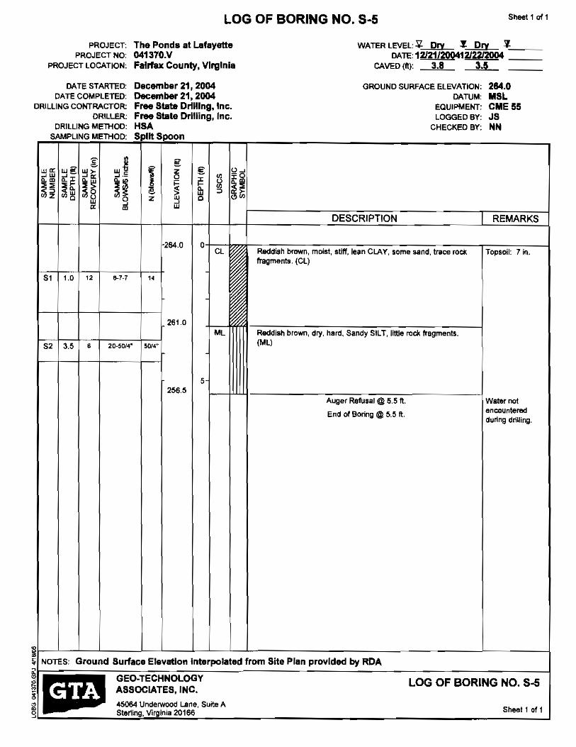
PROJECT: PROJECT NO:
PROJECT LOCATION:
DATE STARTED: DATE COMPLETED:
DRILLING CONTRACTOR: DRILLER:
DRILLING METHOD: SAMPLING METHOD:
g • w~ w€ w> om ~w
~~~~ ~~
~~ ~~ ~~ ~l1 h ~8 ~oa w « ~ m
51 1.0 12
52 3.5 6 20-50/4"
Sheet 1 of 1LOG OF BORING NO. 8-5
The Ponds at l.&fayette WATER lEVEL: ~ Dry ~ Dry '!l-,--:==::041370.V DATE 12121/2OO412122!2OO4 _ Fairfax County, VIrginia CAVED eft): 3.8 3.5
December 21,2004 GROUND SURFACE ELEVATION: 284.0 December 21, 2004 DATUM: MSL Free Stllte Drilling, Inc. EaUIPMENT: CME 55 Free Stille Drilling, Inc. LOGGED BY: J8 HSA CHECK.ED BY: ~N Split Snoon
§: z §: u~~ a 0
u 'i'g~ o~0I ~l;z ~ ~
~
w DESCRIPTION I REMARKS
264.0 a CL Reddish brown, moisl, stlff,lean CLAY, some sana, trace roef::. Topsoil: 7 in.
fragments. (el)
261.0 ML Reddish brown, dry, hard, Sandy SILT, little rock fragments.
(ML)50,14"
5 256.5
Auger Refusal @ 5.5 ft. Watetnot encounteredEnd of Boring @: 5.5 ft. during drilling.
~1-_L-L-L-_L_L-J-~~L- --L-__--1 ~ NOTES: Ground Surface Elevation Interpolated from Site Plan provided by RDA
~f1--- GEO-TECHNOLOGY LOG OF BORING NO. 8-5 ~ I i.:1I ASSOCIATES. INC.
e!) 45064 Underwood Lane, Suite A Sheet 1 of 1 g Sterling, Virginia 20166
APPENDIXC
LABORATORY TEST RESULTS

Boring No.
B-1
B-2
B-4
,
B-7
B-16
B-19
P-1
P-6
GEO-TECHNOLOGY ASSOCIATES, INC. Natural Moisture Content Summary
Lafayette Business Park January 12, 200S
041370.v
Sample No.
8-1
8-2
8-1
8-1
8-2
8-1
8-2
8-1
8-2
8-1
8-2
Bulk
8-1
8-2
Averajte Natural Moisture Content
Natural Moisture
Depth Content (ft) (%)
1.0-2.5 15.7
3.5 - 5.0 11.1
10 - 2.5 20.6
1.0 -2.5 15.1
3.5 - 5.0 9.2
1.0-2.5 12.4
3.5 - 5.0 12.2
1.0 - 2.5 12.0
35 - 5.0 3.8
1.0-2.5 19.3
3.5 - 5.0 11.8
1.0 - 5.0 18.2
1.0 - 2.5 12.7
35 - 5.0 11.1
13.2
nmcLafayetteBusi nessPark-041370

P L A s T I C I T y
I N 0 E X
60
50
40
30
20
10
Cl-ML
0 0 20
V ./
@
V;@
40
@
V
(3
/
60
V
• V
./
60
V
I
100 LIQUID LIMIT
Specimen Identification LL PL PI uses Classification
• B·2 1.• 78 26 52 CH Tannish Brown, Fat CLAY wi Little Sand
III P-1 1.• 36 21 15 CL Reddish Brown. Lean CLAY wi Some Sand
• ~ 0 "0
•0~
•,0~
;;"! . ATTERBERG LIMITS RESULTS !IIJ~ Geo-Technology Assoclales, Inc, 1i: I"~ 45064 Underwood Lane, Suite A Project: Lafayette Business ParkJ ,.:. Ster1ing, Virginia
_ Telephone: 703-478-0055 Location: Fairfax County, Virginia « Fax: 703478-0137 Number: 041370.V 3

--
100
U,S. SIEVE OPENING IN INCHES , US. SIEVE NUMBERS , HYDROMETER
~ • 8N~ ~ '" • ~ ~" • ,. i' , ~I ' f'.-' I' 95
90
1'-as ~
80
75 r-s.. 70
65 >I S:2 60 ;,'" >-55
'" ffi 50 zu: >- 45
'" z
~ 40
a. '" J5
30
25
20
15
10
5
0 100 10 1 0.1 0.01 0.001
GRAIN SIZE IN MiLLIMETERS
GRAVEL I SAND COBBLES : SILT OR CLAY
I coarse I Icoarge I medium J'''' ". Specimen Identification Classification LL PL PI Cc Cu
• B.,2 1.0 Tannish Brown, Fat CLAY wI Little Sand 78 26 52
III p·1 1.0 Reddish Brown. Lean CLAY wI Some Sand 36 21 15
Specimen Identification Nat. Moist. 060 030 010 %Gravel %Sand %Silt& Clay
;:;. B·2 1.0 20.6 0.0 10.4 89.6
gill P-l 1.0 18.2 9.8 18.8 71.4
,,"~
~ GRAIN SIZE DISTRIBUTION
~ 45064 Underwood Lane, Suite A Project: Lafayette Business Park _ir··'--~'oc"" • Sterflng, Virginia ~ Telephone: 7()3-478-Q()55 Location: Fairfax County, Virginia eo Fax: 703-478-0137
Number: 041370.V 3

135
P-1 1.0Source of Material
130 Description of Material Reddish Brown. Lesn CLAY wi Some Sand
VTM"~·,,-1 _Test Method
125 TEST RESULTS
Maximum Dry Density 112.3 PCF Optimum Moisture Content 16.9 %
Natural Moisture Content 18.2 %120 Percent Retained on #4 9.8 %
Corrected Maximum Dry Density 116.1 PCF
Corrected Optimum Moisture Conte~ % 115
NOTE:
SOIL CLASSIFICATIONS 110 uses Classification CL
" AASHTO Classification A-6 ~
g ATTERBERG LIMITS z 105w Q
>- LL PL PI '" 36 21 15'"
100 Curves of 100% Saturation for Specific Gravity Equal 10:
2.80
95 270
260
90
85
I 80
~
75 o 5 10 15 20 25 30 35 40 45~
"J -"W::.A::.TE:::R.:,C:::O:::N.::T.::E:.:NT.::.,:%=-=---,--=-c=-=--,---c-::=_ --,,---,-----1
~ Geo-Technolo9Y Associales. Inc. MOISTURE·DENSITY RELATIONSHIP S: 45064 Underwood Lane, Suite A Project: Lafayette Business Park ~ Sterling, Virginia !!i! Telephone: 703-478-0055 Location: Fairfax County, Virginia ~ Fax: 703478-0137'L- ---l=;;;;..:;.;.:,:;,,;:,;,:,..,.-Number: 041370.v ...J

GEO-TECHNOLOGY ASSOCIATES, INC. STERLING, VIRGINIA CBR (VTM-8) TEST RESULTS
Project Name: Lafayette Business Park Project Number: 041370 Report Dale: 1/12/05
Sample Number: P·1 (Bulk) Depth, ft.: 1.0 USCS Classification: el Condition: SOAKED SU!'l:harge WI., Ibs. 10 Soil + Mold + Basa Plate, gm. 13057 Mold + Base Plate, gm. 7195 Compaction MC, % 17.8 Wet Density of Soli, pet 131.6 Dry Density of Soli, pcf 111.7
Initial Swelling Reading, in. 0.109 Final Swelling Reading, in. 0.123 Swell, % 0.233
Final Moisture, % 18.7 Final Moislure, top 1", % 21.9
Proctor MDD, pcf 112.3
Before Soaking After Soaking Penetration Load Load Load Load (in.) ib. psi. lb. psi.
0.000 a a a a 0.025 84 28 35 12 0.050 144 48 59 20 0.075 192 64 86 29 0.100 231 77 109 36 0.150 300 100 160 53 0.200 360 120 202 67 0.300 444 148 272 91 0.400 492 164 326 10' 0.500 540 180 372 124
CBR Value 0-0.1 :: 3.63 CBR Value 0.05-0.15 = 3.37 CBR Value 0.1-0.2 = 3.10
Page 1

GEO-TECHNOlOGY ASSOCIATES,INC.� STERLING, VIRGINIA� CBR (VTM-8) TEST RESut.TS�
Project Nall'\lt: Larayetta Business PinK� Project Number: 041370� Report Date: 01112105�
LOCATION� Sample Humber: P-1 (Bulk)� Depth, ft.: 1.'�AASKTO Claaalftt:ation� A" Condition: SOAKED Surcharue WI.. Ibs. 10 INITIAl.. DRY DENSITY, PCF 111.7 INITIAl.. MOISTURE. % 17.8 INITiAl COMPACTION, % 99.5 FINAL ORY DENSITY, PCF 110.9 FINAL MOISTURE, % 16.7 FINAL MOISTURE, TOP 1", 0/0 21.9 FINAL COMPACTION, % 98.8 SWELL, % 0.233
CBR Valua (After SoakIng) 3.6 Reemancy Factor 1
Penetration VS. PIston load I1000
I '00
00.
700 ~•" 600 c 0
~ l=:: Bafort! Soakin91 1500 ~
c - -After Soaking I 0 ~ 400•0 ~
300
20.
100
• 0.00 0.10 0.20 0.30 0.40 0.50
Penatration (Inches)
Reviewed By: