Embed Size (px)
Citation preview
The Poor Man’s Guide to
Computer Networks and their Applications
Robin SharpInformatics and Mathematical Modelling, DTU
October 2007
Contents
1 Introduction 2
2 Networks 3
3 Layered Architectures 4
3.1 The OSI Reference Model . . . . . . . . . . . . . . . . . . . . . . . . . . . . . . . . 4
3.2 Other layered architectures . . . . . . . . . . . . . . . . . . . . . . . . . . . . . . . 8
4 Services and Protocols 10
4.1 Services . . . . . . . . . . . . . . . . . . . . . . . . . . . . . . . . . . . . . . . . . . 10
4.2 Quality of Service . . . . . . . . . . . . . . . . . . . . . . . . . . . . . . . . . . . . . 15
4.3 Protocols . . . . . . . . . . . . . . . . . . . . . . . . . . . . . . . . . . . . . . . . . 16
5 Network Technology 21
5.1 Routers . . . . . . . . . . . . . . . . . . . . . . . . . . . . . . . . . . . . . . . . . . 22
5.2 Bridges . . . . . . . . . . . . . . . . . . . . . . . . . . . . . . . . . . . . . . . . . . 23
5.3 LAN Technologies . . . . . . . . . . . . . . . . . . . . . . . . . . . . . . . . . . . . 24
6 Basic Protocols in the Internet 30
6.1 Internet Protocol, IP . . . . . . . . . . . . . . . . . . . . . . . . . . . . . . . . . . . 30
6.2 Transmission Control Protocol, TCP . . . . . . . . . . . . . . . . . . . . . . . . . . 37
6.3 User Datagram Protocol, UDP . . . . . . . . . . . . . . . . . . . . . . . . . . . . . 43
6.4 Internet Application Layer Protocols . . . . . . . . . . . . . . . . . . . . . . . . . . 43
7 Simple Mail Transfer Protocol, SMTP 44
7.1 The Basic SMTP protocol . . . . . . . . . . . . . . . . . . . . . . . . . . . . . . . . 45
7.2 MIME . . . . . . . . . . . . . . . . . . . . . . . . . . . . . . . . . . . . . . . . . . . 49
1
2 1 INTRODUCTION
8 HTTP and the World Wide Web 52
8.1 Uniform Resource Identifiers . . . . . . . . . . . . . . . . . . . . . . . . . . . . . . 54
8.2 Hypertext Transfer Protocols . . . . . . . . . . . . . . . . . . . . . . . . . . . . . . 55
9 Network Programming with Sockets 60
9.1 Java Client Sockets . . . . . . . . . . . . . . . . . . . . . . . . . . . . . . . . . . . . 61
9.2 Java Server Sockets . . . . . . . . . . . . . . . . . . . . . . . . . . . . . . . . . . . . 66
10 Remote Procedures and Objects 67
10.1 Remote Procedure Call . . . . . . . . . . . . . . . . . . . . . . . . . . . . . . . . . 67
10.2 Binding . . . . . . . . . . . . . . . . . . . . . . . . . . . . . . . . . . . . . . . . . . 70
10.3 Remote Object Invocation . . . . . . . . . . . . . . . . . . . . . . . . . . . . . . . . 70
11 CORBA 78
11.1 The Object Request Broker . . . . . . . . . . . . . . . . . . . . . . . . . . . . . . . 79
11.2 CORBA Interfaces and the CORBA IDL . . . . . . . . . . . . . . . . . . . . . . . 80
11.3 CORBA Clients and Servers . . . . . . . . . . . . . . . . . . . . . . . . . . . . . . . 82
12 Web Services and SOAP 88
12.1 XML Encoding of the Request Message . . . . . . . . . . . . . . . . . . . . . . . . 89
12.2 SOAP Response Messages . . . . . . . . . . . . . . . . . . . . . . . . . . . . . . . . 91
12.3 SOAP Types . . . . . . . . . . . . . . . . . . . . . . . . . . . . . . . . . . . . . . . 93
12.4 Web Service Clients and Servers . . . . . . . . . . . . . . . . . . . . . . . . . . . . 95
13 Further Reading 100
1 Introduction
These days, computers very rarely operate on their own. Instead, they are connectedtogether by computer networks which enable them to exchange information. There can bemany reasons for wanting to do this in relation to a particular computer application. Forexample:
• The application may directly involve transfer of information between human users,as in systems for transferring e-mail or other documents, or in teleconferencing.
• The application may involve a need to access an information base of some kind, asin searching the World Wide Web, electronic banking or database applications.
• The application may need several computers to collaborate on performing a largecalculation, or to share data or other resources, as in many technical computationsin engineering, the natural sciences and economic modelling.
The aim of these notes is to present the main concepts of computer networks, give a veryshort introduction to their architecture and technology and give some simple examples
3
of how the use of networks can be incorporated into applications. There are many bookswhich deal with the subject in much more detail. You should consult some of the referencesin the bibliography if you want to know more about a particular topic.
2 Networks
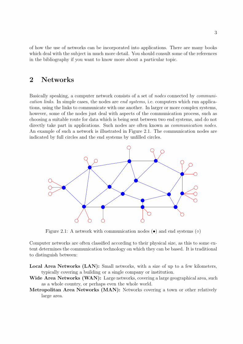
Basically speaking, a computer network consists of a set of nodes connected by communi-cation links. In simple cases, the nodes are end systems, i.e. computers which run applica-tions, using the links to communicate with one another. In larger or more complex systems,however, some of the nodes just deal with aspects of the communication process, such aschoosing a suitable route for data which is being sent between two end systems, and do notdirectly take part in applications. Such nodes are often known as communication nodes.An example of such a network is illustrated in Figure 2.1. The communication nodes areindicated by full circles and the end systems by unfilled circles.
Figure 2.1: A network with communication nodes (•) and end systems (◦)
Computer networks are often classified according to their physical size, as this to some ex-tent determines the communication technology on which they can be based. It is traditionalto distinguish between:
Local Area Networks (LAN): Small networks, with a size of up to a few kilometers,typically covering a building or a single company or institution.
Wide Area Networks (WAN): Large networks, covering a large geographical area, suchas a whole country, or perhaps even the whole world.
Metropolitan Area Networks (MAN): Networks covering a town or other relativelylarge area.
4 3 LAYERED ARCHITECTURES
Some of these distinctions are historically based, since for legal reasons it was at one timeimportant whether the network was run by and for a single owner such as a company oruniversity (who were only allowed to set up a LAN covering a limited area), or whetherthe network’s capacity was intended to be sold to subscribers in general (typically a WAN,which could only be run by an privileged telecommunications monopoly). Nowadays, wheretelecommunication services have in most countries been extensively liberalised, this typeof criterion is less important. However, the basic differences in technology remain. Wediscuss some of these below in Section 5.
3 Layered Architectures
The requirement that some nodes in a computer network should be able to do more thanothers leads naturally to the idea that systems in a network can be built up as a numberof layers, where the upper layers add some kind of extra functionality to the lower ones.Thus for example, an end system can be built up as a communication node with one ormore extra layers to add the functions needed for dealing with the requirements of theapplications.
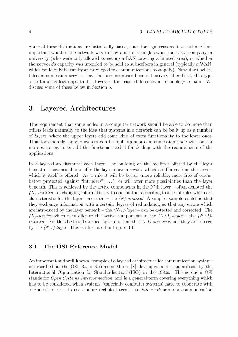
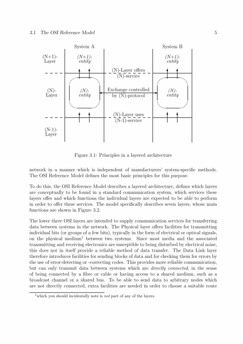
In a layered architecture, each layer – by building on the facilities offered by the layerbeneath – becomes able to offer the layer above a service which is different from the servicewhich it itself is offered. As a rule it will be better (more reliable, more free of errors,better protected against “intruders”, . . . ) or will offer more possibilities than the layerbeneath. This is achieved by the active components in the N’th layer – often denoted the(N)-entities – exchanging information with one another according to a set of rules which arecharacteristic for the layer concerned – the (N)-protocol. A simple example could be thatthey exchange information with a certain degree of redundancy, so that any errors whichare introduced by the layer beneath – the (N-1)-layer – can be detected and corrected. The(N)-service which they offer to the active components in the (N+1)-layer – the (N+1)-entities – can thus be less disturbed by errors than the (N-1)-service which they are offeredby the (N-1)-layer. This is illustrated in Figure 3.1.
3.1 The OSI Reference Model
An important and well-known example of a layered architecture for communication systemsis described in the OSI Basic Reference Model [8] developed and standardised by theInternational Organization for Standardization (ISO) in the 1980s. The acronym OSIstands for Open Systems Interconnection, and is a general term covering everything whichhas to be considered when systems (especially computer systems) have to cooperate withone another, or – to use a more technical term – to interwork across a communication
3.1 The OSI Reference Model 5
(N+1)-entity
(N+1)-entity
(N)-entity
'
&
$
%(N)-entity
'
&
$
%(N)-Layer
(N+1)-Layer
(N-1)-Layer
� -Exchange controlledby (N)-protocol
(N)-Layer offers(N)-service
(N)-Layer uses(N-1)-service
6 6 6 6
6 6 6 6
System A System B
Figure 3.1: Principles in a layered architecture
network in a manner which is independent of manufacturers’ system-specific methods.The OSI Reference Model defines the most basic principles for this purpose.
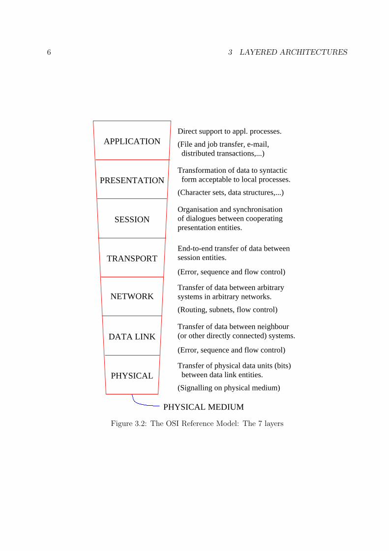
To do this, the OSI Reference Model describes a layered architecture, defines which layersare conceptually to be found in a standard communication system, which services theselayers offer and which functions the individual layers are expected to be able to performin order to offer these services. The model specifically describes seven layers, whose mainfunctions are shown in Figure 3.2.
The lower three OSI layers are intended to supply communication services for transferringdata between systems in the network. The Physical layer offers facilities for transmittingindividual bits (or groups of a few bits), typically in the form of electrical or optical signals,on the physical medium1 between two systems. Since most media and the associatedtransmitting and receiving electronics are susceptible to being disturbed by electrical noise,this does not in itself provide a reliable method of data transfer. The Data Link layertherefore introduces facilities for sending blocks of data and for checking them for errors bythe use of error-detecting or -correcting codes. This provides more reliable communication,but can only transmit data between systems which are directly connected, in the senseof being connected by a fibre or cable or having access to a shared medium, such as abroadcast channel or a shared bus. To be able to send data to arbitrary nodes whichare not directly connected, extra facilities are needed in order to choose a suitable route
1which you should incidentally note is not part of any of the layers.
6 3 LAYERED ARCHITECTURES
PHYSICAL MEDIUM
PHYSICAL
DATA LINK
NETWORK
TRANSPORT
SESSION
PRESENTATION
APPLICATION (File and job transfer, e-mail, distributed transactions,...)
Transformation of data to syntactic form acceptable to local processes.
(Character sets, data structures,...)
Organisation and synchronisationof dialogues between cooperatingpresentation entities.
End-to-end transfer of data betweensession entities.
Transfer of data between arbitrarysystems in arbitrary networks.
(Routing, subnets, flow control)
Transfer of data between neighbour(or other directly connected) systems.
(Error, sequence and flow control)
Transfer of physical data units (bits) between data link entities.
(Signalling on physical medium)
(Error, sequence and flow control)
Direct support to appl. processes.
Figure 3.2: The OSI Reference Model: The 7 layers
3.1 The OSI Reference Model 7
TT
N
D
N
D
End system End systemCommunication network
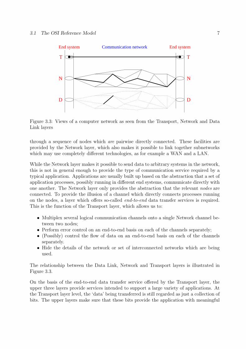
Figure 3.3: Views of a computer network as seen from the Transport, Network and DataLink layers
through a sequence of nodes which are pairwise directly connected. These facilities areprovided by the Network layer, which also makes it possible to link together subnetworkswhich may use completely different technologies, as for example a WAN and a LAN.
While the Network layer makes it possible to send data to arbitrary systems in the network,this is not in general enough to provide the type of communication service required by atypical application. Applications are usually built up based on the abstraction that a set ofapplication processes, possibly running in different end systems, communicate directly withone another. The Network layer only provides the abstraction that the relevant nodes areconnected. To provide the illusion of a channel which directly connects processes runningon the nodes, a layer which offers so-called end-to-end data transfer services is required.This is the function of the Transport layer, which allows us to:
• Multiplex several logical communication channels onto a single Network channel be-tween two nodes;
• Perform error control on an end-to-end basis on each of the channels separately;• (Possibly) control the flow of data on an end-to-end basis on each of the channels
separately.• Hide the details of the network or set of interconnected networks which are being
used.
The relationship between the Data Link, Network and Transport layers is illustrated inFigure 3.3.
On the basis of the end-to-end data transfer service offered by the Transport layer, theupper three layers provide services intended to support a large variety of applications. Atthe Transport layer level, the ‘data’ being transferred is still regarded as just a collection ofbits. The upper layers make sure that these bits provide the application with meaningful
8 3 LAYERED ARCHITECTURES
data in a form which the application can understand. The Session layer is used to organisedialogues between two or more parties involved in an application, the Presentation layerconverts data into a representation which the application in the receiving system can under-stand, and the Application layer offers functionality such as transfer of files or coordinationof parallel activities, which are required in general by applications, or facilities such as mailor Web transfer required by particular applications. We shall look more closely at someexamples of particular Application protocols later in these notes. Note that the applicationitself is – like the physical medium – not covered by the model. The application processesare to be considered as users of the facilities offered by the Application layer.
The importance of the OSI Reference Model is that it introduced a standard architectureand a standard notation for many concepts related to data communication. The termsgiven in italics above are examples of terms introduced in the model. That, for example,there are seven layers is relatively unimportant, and the explanations of why there shouldbe exactly seven are mostly entertaining rather than strictly technical. In practice, for de-scriptive purposes some of the layers (particularly the Data Link, Network and Applicationlayers) are often divided into sub-layers, while implementations, on the other hand, oftenimplement several layers as a single unit.
3.2 Other layered architectures
The OSI Reference Model architecture is not the only layered architecture which youmay meet in communication systems. Several commercial manufacturers have developedproducts which are structured in a similar way. Well-known examples are IBM’s SNAarchitecture and Digital’s DECNET. Naturally, the protocols used are not in general thesame as OSI protocols, and the layers do not always correspond exactly to the OSI ones,especially in the so-called Upper Layers: the OSI Session, Presentation and Applicationlayers.
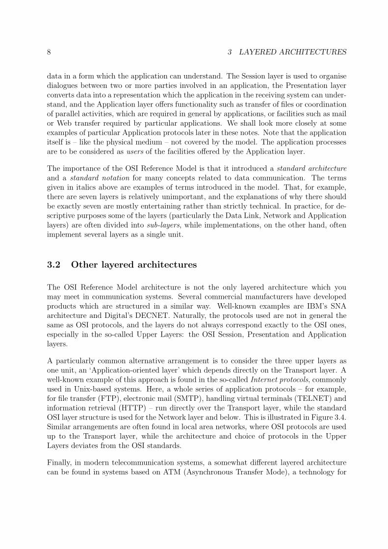
A particularly common alternative arrangement is to consider the three upper layers asone unit, an ‘Application-oriented layer’ which depends directly on the Transport layer. Awell-known example of this approach is found in the so-called Internet protocols, commonlyused in Unix-based systems. Here, a whole series of application protocols – for example,for file transfer (FTP), electronic mail (SMTP), handling virtual terminals (TELNET) andinformation retrieval (HTTP) – run directly over the Transport layer, while the standardOSI layer structure is used for the Network layer and below. This is illustrated in Figure 3.4.Similar arrangements are often found in local area networks, where OSI protocols are usedup to the Transport layer, while the architecture and choice of protocols in the UpperLayers deviates from the OSI standards.
Finally, in modern telecommunication systems, a somewhat different layered architecturecan be found in systems based on ATM (Asynchronous Transfer Mode), a technology for
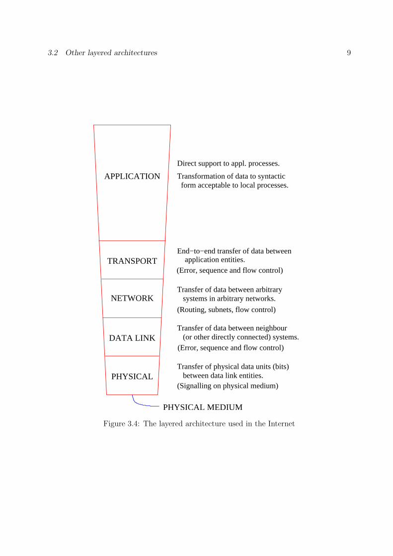
3.2 Other layered architectures 9
(Routing, subnets, flow control)
(Error, sequence and flow control)
(Signalling on physical medium)
(Error, sequence and flow control) application entities.
PHYSICAL MEDIUM
Direct support to appl. processes.
Transformation of data to syntactic form acceptable to local processes.
PHYSICAL
DATA LINK
NETWORK
TRANSPORT
Transfer of data between arbitrary
Transfer of data between neighbour
Transfer of physical data units (bits)
APPLICATION
End−to−end transfer of data between
between data link entities.
(or other directly connected) systems.
systems in arbitrary networks.
Figure 3.4: The layered architecture used in the Internet
10 4 SERVICES AND PROTOCOLS
supporting high-speed transfer of data over a local area or wide area network. This archi-tecture is described by the Broadband ISDN Protocol Reference Model (B-ISDN PRM) [27].In this model, although the layers roughly correspond to the OSI RM, there are severalimportant technical differences, especially with respect to the way in which control andsignalling information is transferred: In OSI, it forms part of the ordinary data flow; inB-ISDN, it is transferred over a separate connection.
4 Services and Protocols
The service offered by a layer describes the facilities offered by the layer viewed as a ‘blackbox’. In other words the service describes what the layer offers without telling us how thisis achieved. The protocol is the set of rules for how to behave in order to offer the requiredservice. This is analogous to concepts used in program design: the service corresponds toa description of an interface and the protocol to its implementation.
4.1 Services
Properties of services fall into two general classes, one concerned with the logical operationof the service (“what does it do?”), and the other with its economy (“what does it cost?”).In these notes, we shall only look at the logical properties of services. Important onesinclude:
• Sequence preservation• Data unit synchronisation• Freedom from error• Connection-orientation• (N)-peer operation• Simplex/duplex/multiplex operation• Expedited data• Security
Let us look at these concepts in turn.
4.1.1 Sequence preservation
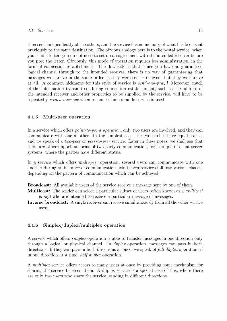
In a service which offers sequence preservation, messages sent by a sender are received inthe same order as they were sent. This property of a service can be extremely important tosome types of service user. For example, in an application in which video frames are to be
4.1 Services 11
1234512345 Service
12345 Service
Cut anywhere
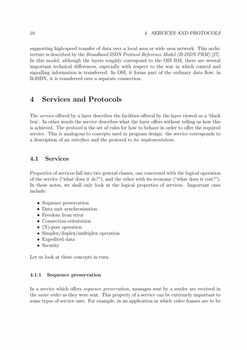
Figure 4.1: A block-oriented service (above) and a stream-oriented service (below).
transferred from one system to another for immediate display, it would be very inconvenientif the frames arrived in a different order, as the application would then itself have to managethe task of buffering and re-ordering them before display. Likewise, changes to a databaseshould not arrive in a different order than the one chosen by the user. On the other hand,for an application which transfers numbered disk blocks from one system to another, inorder to maintain identical copies of a disk on two systems, sequence preservation is oftenirrelevant.
4.1.2 Data unit synchronisation
In a service which offers data unit synchronisation, there is a one-to-one correspondencebetween the messages passed to the service for transmission and the messages deliveredto the receivers. In other words, each message supplied by a user for transmission will –if it arrives at all – be delivered to the intended receiver(s) as a unit. Such services aresometimes called message oriented services or block oriented services, as they deliver blocksof data in their entirety.
A common alternative is for the service to be stream oriented. This means that the bound-aries between units of data supplied to the service are not necessarily preserved when thedata are delivered to the receiver. Data are regarded as making up a (potentially endless)stream, which can be chopped up and delivered in units of any convenient size. This isillustrated in Figure 4.1.
4.1.3 Freedom from error
An error-free service delivers the same messages as those which are sent off, without lossor corruption of any kind. In communication systems, the basic types of error are:
12 4 SERVICES AND PROTOCOLS
Message loss: the receiver fails to receive a message which has been sent by the sender.Message corruption: the receiver receives a message which differs from that sent by the
sender.Spurious message: the receiver receives a message which has not been sent by the (ap-
parent) sender.
Other types of error, such as duplication or misdelivery of messages, can be expressed ascombinations of these basic error types.
A service is often described in terms of its error rate, which roughly speaking is the numberof erroneous units of data as a fraction of the number of units of data which the sendertries to send. Common measures of this are:
• Bit Error Rate (BER), measured as the number of bits which are in error as a fractionof the total number of bits sent.
• Residual Error Rate (RER), measured as the number of erroneous blocks of data asa fraction of the number of blocks sent:
RER =Nl + Nc + Nu
Ns + Nu
where Ns is the number of blocks sent by the sender, Nc the number of corruptedblocks received, Nl the number of lost blocks and Nu the number of spurious blocksreceived by the receiver (but not sent by the genuine sender).
4.1.4 Connection-orientation
In a connection-mode service, the users of the service have to establish a connection withone another before they can exchange ‘real’ data. The connection is a logical channelthrough which the real data will be sent, and is set up by exchange of particular types ofmessage in a so-called connection establishment phase of communication. This is followedby the data transfer phase of communication, in which actual data are exchanged, andfinally by a connection release phase, in which the connection is broken. For a reliableservice, connection release will of course be something which the users decide voluntarilyto do; an unreliable service can also produce involuntary release of a connection (in OSIjargon known as a Provider Abort). You probably recognise this style of operation fromthe ordinary telephone service, which is the archetypal example of a connection-orientedservice, where you have to set up the connection before you can exchange ‘data’. In thecase of an old-fashioned telephone the data will of course be in the form of digital or analogencoded speech; in more modern systems other possibilities may also be available.
The alternative to this mode of operation is seen in a connectionless-mode service. Here, itis not necessary to set up a connection before exchange of data. Essentially, each message is
4.1 Services 13
then sent independently of the others, and the service has no memory of what has been sentpreviously to the same destination. The obvious analogy here is to the postal service: whenyou send a letter, you do not need to set up an agreement with the intended receiver beforeyou post the letter. Obviously, this mode of operation requires less administration, in theform of connection establishment. The downside is that, since you have no guaranteedlogical channel through to the intended receiver, there is no way of guaranteeing thatmessages will arrive in the same order as they were sent – or even that they will arriveat all. A common nickname for this style of service is send-and-pray ! Moreover, muchof the information transmitted during connection establishment, such as the address ofthe intended receiver and other properties to be supplied by the service, will have to berepeated for each message when a connectionless-mode service is used.
4.1.5 Multi-peer operation
In a service which offers point-to-point operation, only two users are involved, and they cancommunicate with one another. In the simplest case, the two parties have equal status,and we speak of a two-peer or peer-to-peer service. Later in these notes, we shall see thatthere are other important forms of two-party communication, for example in client-serversystems, where the parties have different status.
In a service which offers multi-peer operation, several users can communicate with oneanother during an instance of communication. Multi-peer services fall into various classes,depending on the pattern of communication which can be achieved:
Broadcast: All available users of the service receive a message sent by one of them.
Multicast: The sender can select a particular subset of users (often known as a multicastgroup) who are intended to receive a particular message or messages.
Inverse broadcast: A single receiver can receive simultaneously from all the other serviceusers.
4.1.6 Simplex/duplex/multiplex operation
A service which offers simplex operation is able to transfer messages in one direction onlythrough a logical or physical channel. In duplex operation, messages can pass in bothdirections. If they can pass in both directions at once, we speak of full duplex operation; ifin one direction at a time, half duplex operation.
A multiplex service offers access to many users at once by providing some mechanism forsharing the service between them. A duplex service is a special case of this, where thereare only two users who share the service, sending in different directions.
14 4 SERVICES AND PROTOCOLS
4.1.7 Expedited data
Expedited data is an OSI term for data to be transferred with high priority. By definition,expedited data will arrive not later than ‘ordinary’ data sent subsequently to the samedestination, and may arrive before ordinary data sent to the same destination at an earlierinstant of time. Note that this is not a guarantee that they will arrive before ordinary datasent at the same time! In Internet protocols, the term urgent data is used for essentiallythe same concept.
To model this, we can model the service as containing a prioritised queue for the messagesin transit, so that queue elements sent via the expedited data service can overtake thosesent via the normal service. Obviously, this is in conflict with the concept of sequencepreservation for messages sent between two service users, seen from a universal point ofview. But the individual services (normal and expedited) may each possess the sequencepreservation property when considered separately.
Although the OSI term is confined to a single high-priority service, the concept can begeneralised to cover arbitrary numbers of priority levels. This type of service is commonlyoffered at the hardware level in Local Area Networks. Examples are the ISO/IEEE TokenBus [11], which offers four levels of priority, and the ISO/IEEE Token Ring [12], whichoffers eight levels.
4.1.8 Security
A secure service is one which prevents unauthorised persons from obtaining access to datatransferred by it. This means that data cannot be read or altered by parties other thanthe intended sender and receiver(s). This is a matter of extreme practical importance, anda great deal of effort has been expended on developing methods to protect data in transitfrom ‘intruders’.
Various types of security can be identified. A generally accepted classification is:
Confidentiality: A confidential service provides protection of data from unauthoriseddisclosure. This protection may, for example, cover:
1. All data sent between users of the service,2. Particular fields within data (for example, fields containing passwords or keys),3. Information about the amount of data traffic being transmitted.
The primary mechanism for ensuring confidentiality of data is encipherment, and astudy of cryptography is essential for understanding the issues involved.
Integrity: A service offering (data) integrity takes measures to withstand active attemptsto modify data being passed via the service. As with confidentiality, all data may beprotected, or only selected fields.
4.2 Quality of Service 15
Availability: A service which ensures availability is designed to make the service availableto (authorised) users at all times. It is not possible for intruders to prevent access byattacking the systems which provide the service. As you may know, typical attacksmay come in the form of vira, worms, trojan horses or by the service being floodedwith excessive numbers of messages (so-called denial of service (DoS) attacks).
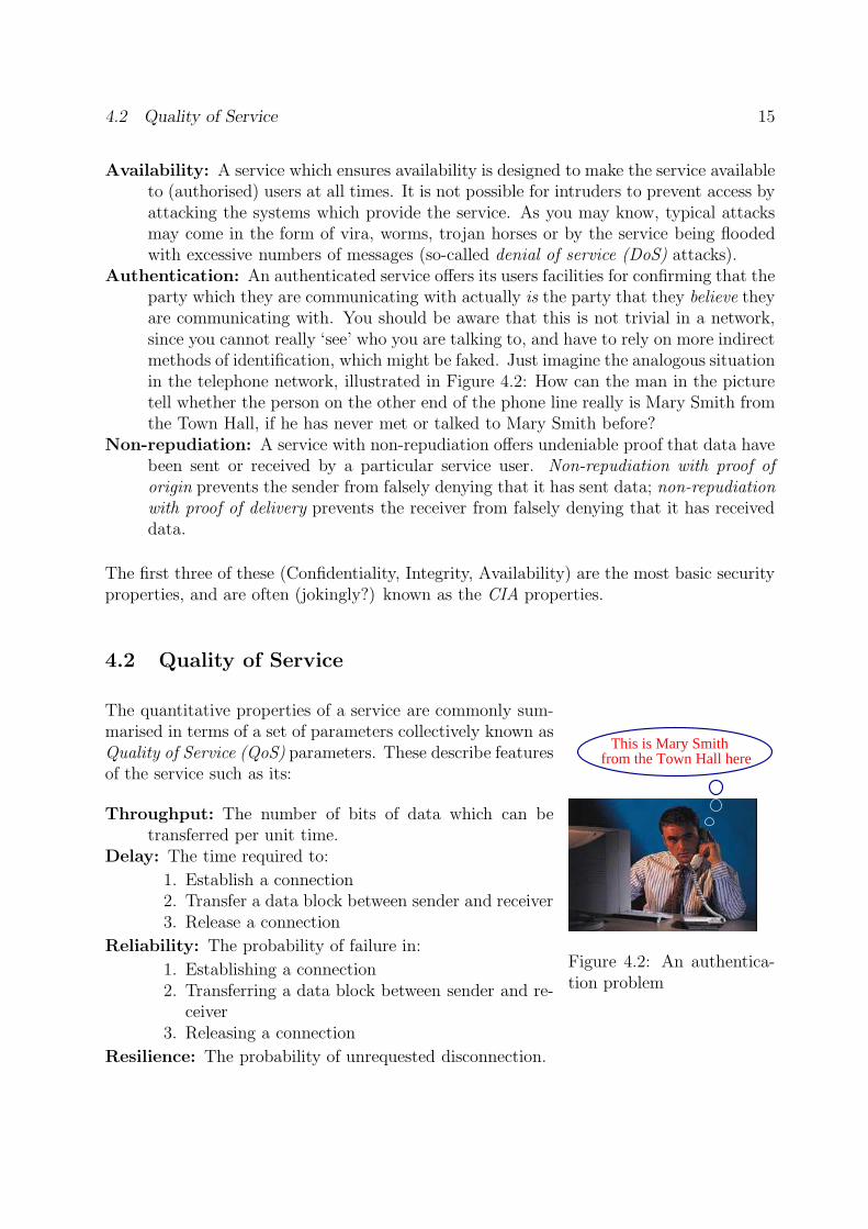
Authentication: An authenticated service offers its users facilities for confirming that theparty which they are communicating with actually is the party that they believe theyare communicating with. You should be aware that this is not trivial in a network,since you cannot really ‘see’ who you are talking to, and have to rely on more indirectmethods of identification, which might be faked. Just imagine the analogous situationin the telephone network, illustrated in Figure 4.2: How can the man in the picturetell whether the person on the other end of the phone line really is Mary Smith fromthe Town Hall, if he has never met or talked to Mary Smith before?
Non-repudiation: A service with non-repudiation offers undeniable proof that data havebeen sent or received by a particular service user. Non-repudiation with proof oforigin prevents the sender from falsely denying that it has sent data; non-repudiationwith proof of delivery prevents the receiver from falsely denying that it has receiveddata.
The first three of these (Confidentiality, Integrity, Availability) are the most basic securityproperties, and are often (jokingly?) known as the CIA properties.
4.2 Quality of Service
This is Mary Smithfrom the Town Hall here
Figure 4.2: An authentica-tion problem
The quantitative properties of a service are commonly sum-marised in terms of a set of parameters collectively known asQuality of Service (QoS) parameters. These describe featuresof the service such as its:
Throughput: The number of bits of data which can betransferred per unit time.
Delay: The time required to:
1. Establish a connection2. Transfer a data block between sender and receiver3. Release a connection
Reliability: The probability of failure in:
1. Establishing a connection2. Transferring a data block between sender and re-
ceiver3. Releasing a connection
Resilience: The probability of unrequested disconnection.
16 4 SERVICES AND PROTOCOLS
Error rate: The BER and/or RER (as defined above).Protection: Degree of protection against intruders who at-
tempt:
1. Passive monitoring of information in transit.2. Active modification, replay, addition or deletion of information in transit.
Priority: This can be understood in two senses:
1. Priority in delivery of data. High priority data is delivered “faster”.2. Priority in maintaining the requested QoS if the service provider has to degrade
the service for some users. A high priority service in this sense is more likely toget what was requested.
QoS parameters are often specified in terms of a target (mean or median) value, togetherwith some indication of the acceptable spread of values, given for example in terms ofpermissible maximum and minimum values or in terms of a variance. It may also berelevant to specify a (prioritised) list of acceptable discrete values. For example, you mightwant to state that a service offers (or is requested to offer):
• Throughput: Preferably 128 kbit/s, but otherwise 56 kbit/s.• Delay in data transfer: 200 ms., +5 ms./-10 ms.• Resilience: 1 · 10−8
• BER: 1 · 10−9.• Priority in delivery: Highest.
The importance of the various parameters depends strongly on the type of data beingtransferred by the service. For example, the variation in data transfer delay (often knownas the jitter) is relatively unimportant for transfer of data such as text files, whereas it is avery important parameter for transfer of continuous media, such as live video or audio ina multimedia application, where variations in the delay can markedly reduce the qualityof the user’s experience.
4.3 Protocols
A communication protocol is a set of rules which describe how a set of parties are to behavein order to achieve successful communication, which in a layered architecture means thatthey provide the service which the layer is supposed to provide. Typically the rules specify:
• Which messages are to be exchanged in response to particular events which occureither at the interface to the layer or internally (say in the form of timeouts). Suchrules are known as the rules of procedure for the protocol.
• The format and encoding of the messages for transfer between the participating en-tities.
4.3 Protocols 17
������������
������������
������������
������������
(N)−SDU
(N)−SDU
(N)−SAP
Transmission
via (N)−Protocol
(N+1)−Layer
(N)−Layer
(N)−PDU
(N)−PCI
(N)−PCI
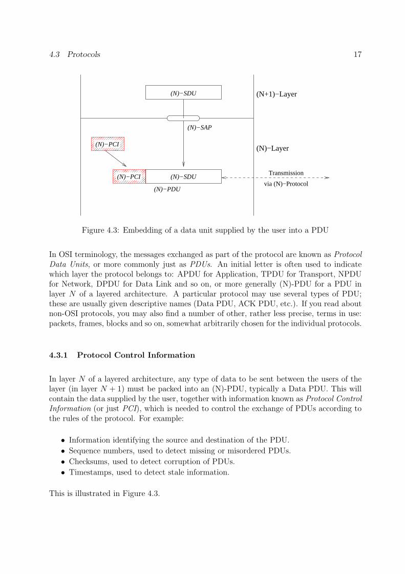
Figure 4.3: Embedding of a data unit supplied by the user into a PDU
In OSI terminology, the messages exchanged as part of the protocol are known as ProtocolData Units, or more commonly just as PDUs. An initial letter is often used to indicatewhich layer the protocol belongs to: APDU for Application, TPDU for Transport, NPDUfor Network, DPDU for Data Link and so on, or more generally (N)-PDU for a PDU inlayer N of a layered architecture. A particular protocol may use several types of PDU;these are usually given descriptive names (Data PDU, ACK PDU, etc.). If you read aboutnon-OSI protocols, you may also find a number of other, rather less precise, terms in use:packets, frames, blocks and so on, somewhat arbitrarily chosen for the individual protocols.
4.3.1 Protocol Control Information
In layer N of a layered architecture, any type of data to be sent between the users of thelayer (in layer N + 1) must be packed into an (N)-PDU, typically a Data PDU. This willcontain the data supplied by the user, together with information known as Protocol ControlInformation (or just PCI), which is needed to control the exchange of PDUs according tothe rules of the protocol. For example:
• Information identifying the source and destination of the PDU.
• Sequence numbers, used to detect missing or misordered PDUs.
• Checksums, used to detect corruption of PDUs.
• Timestamps, used to detect stale information.
This is illustrated in Figure 4.3.
18 4 SERVICES AND PROTOCOLS
The figure illustrates a simple case, where the amount of data supplied (in the figuredenoted the Service Data Unit or SDU, in accordance with OSI notation) can convenientlyfit into a single PDU, and where all the PCI is added as a header at the start of the PDU.In more complex cases, some of the PCI may appear in a trailer at the end of the PDU2,or it may be necessary to:
• Divide the data in the SDU up among several PDUs. This is usually known assegmentation or fragmentation. The opposite process, known as reassembly takesplace in the receiver, in order to recover the entire SDU with all its parts in thecorrect order.
• Include several SDUs in a single PDU. This process, known as packing, may beconvenient for efficiency reasons. The receiver will then have the task of unpackingthe SDUs for delivery to the users.
Some types of PDU, used for purely administrative purposes such as acknowledging receiptof a PDU, do not need to contain data supplied by the service user, and thus consist solelyof PCI.
4.3.2 PCI in a layered architecture
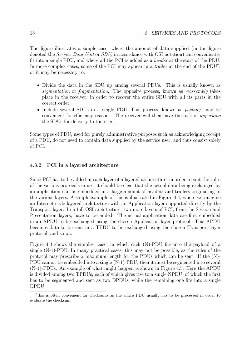
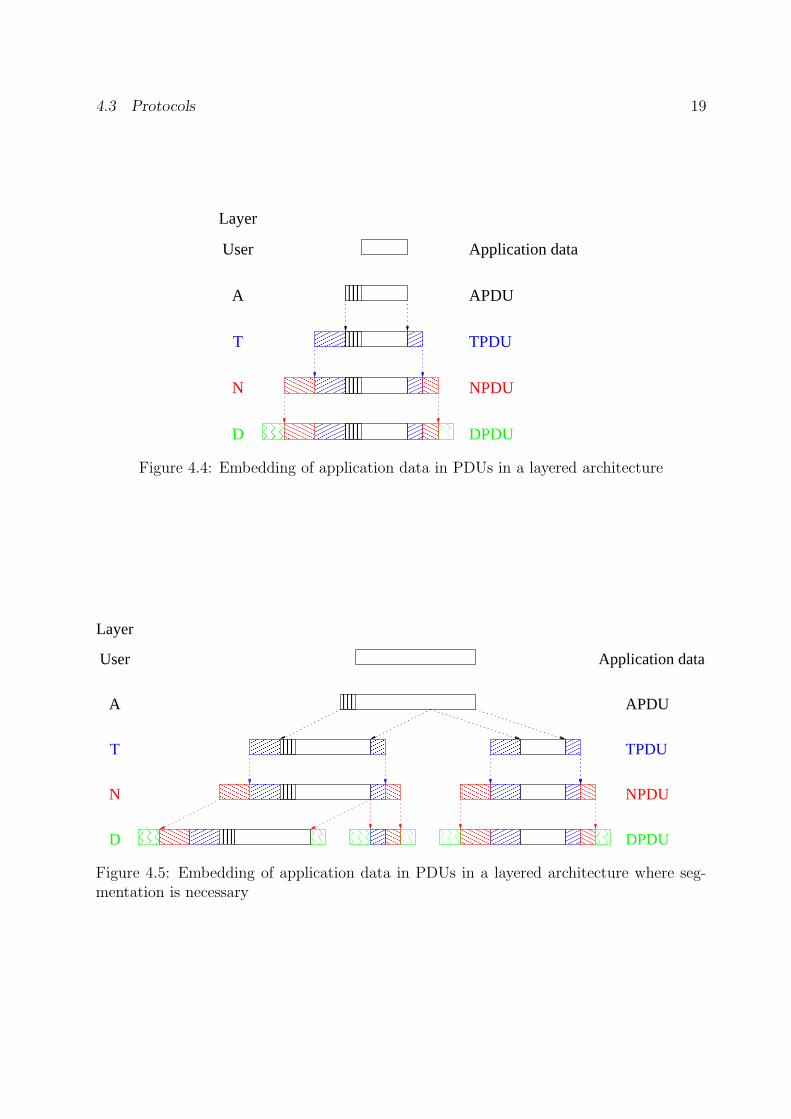
Since PCI has to be added in each layer of a layered architecture, in order to suit the rulesof the various protocols in use, it should be clear that the actual data being exchanged byan application can be embedded in a large amount of headers and trailers originating inthe various layers. A simple example of this is illustrated in Figure 4.4, where we imaginean Internet-style layered architecture with an Application layer supported directly by theTransport layer. In a full OSI architecture, two more layers of PCI, from the Session andPresentation layers, have to be added. The actual application data are first embeddedin an APDU to be exchanged using the chosen Application layer protocol. This APDUbecomes data to be sent in a TPDU to be exchanged using the chosen Transport layerprotocol, and so on.
Figure 4.4 shows the simplest case, in which each (N)-PDU fits into the payload of asingle (N-1)-PDU. In many practical cases, this may not be possible, as the rules of theprotocol may prescribe a maximum length for the PDUs which can be sent. If the (N)-PDU cannot be embedded into a single (N-1)-PDU, then it must be segmented into several(N-1)-PDUs. An example of what might happen is shown in Figure 4.5. Here the APDUis divided among two TPDUs, each of which gives rise to a single NPDU, of which the firsthas to be segmented and sent as two DPDUs, while the remaining one fits into a singleDPDU.
2this is often convenient for checksums as the entire PDU usually has to be processed in order toevaluate the checksum.
4.3 Protocols 19
������
������
������
������
������
������
���
���
���
���
���
���
������������
��������
������
������
������
������
���
���
���
���
��������
��������
��������
��������
A
T
N
D
TPDU
NPDU
DPDU
Application data
APDU
Layer
User
Figure 4.4: Embedding of application data in PDUs in a layered architecture
������
������
���
���
������
������
���
���
������
������
���
���
������
������
���
���
������
������
���
���
������������
��������
A
T
N
D
Layer
User
������
������
������
������
������
������
��������������������
��������������������
��������������������
��������������������
��������������������
��������������������
���
���
���
���
���
���
������������
�����������
���
���
���
��������
��������
��������
��������
������������������
������
��������
������
����������
����������������
��������������������
TPDU
NPDU
DPDU
APDU
Application data
Figure 4.5: Embedding of application data in PDUs in a layered architecture where seg-mentation is necessary
20 4 SERVICES AND PROTOCOLS
(a)
(b) s d c
s d l b ct
t
DATA PDU
ACK PDU
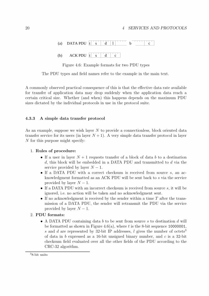
Figure 4.6: Example formats for two PDU types
The PDU types and field names refer to the example in the main text.
A commonly observed practical consequence of this is that the effective data rate availablefor transfer of application data may drop suddenly when the application data reach acertain critical size. Whether (and when) this happens depends on the maximum PDUsizes dictated by the individual protocols in use in the protocol suite.
4.3.3 A simple data transfer protocol
As an example, suppose we wish layer N to provide a connectionless, block oriented datatransfer service for its users (in layer N + 1). A very simple data transfer protocol in layerN for this purpose might specify:
1. Rules of procedure:
• If a user in layer N + 1 requests transfer of a block of data b to a destinationd, this block will be embedded in a DATA PDU and transmitted to d via theservice provided by layer N − 1.
• If a DATA PDU with a correct checksum is received from source s, an ac-knowledgment formatted as an ACK PDU will be sent back to s via the serviceprovided by layer N − 1.
• If a DATA PDU with an incorrect checksum is received from source s, it will beignored, i.e. no action will be taken and no acknowledgment sent.
• If no acknowledgment is received by the sender within a time T after the trans-mission of a DATA PDU, the sender will retransmit the PDU via the serviceprovided by layer N − 1.
2. PDU formats:
• A DATA PDU containing data b to be sent from source s to destination d willbe formatted as shown in Figure 4.6(a), where t is the 8-bit sequence 10000001,s and d are represented by 32-bit IP addresses, l gives the number of octets3
of data in b expressed as a 16-bit unsigned binary number, and c is a 32-bitchecksum field evaluated over all the other fields of the PDU according to theCRC-32 algorithm.
38-bit units
21
• An ACK PDU to be sent from destination d to source s will be formatted asshown in Figure 4.6(b), where t is the 8-bit sequence 10000010, s and d arerepresented by 32-bit IP addresses, and c is a 32-bit checksum field evaluatedover all the other fields of the PDU according to the CRC-32 algorithm.
More complicated rules of procedure and a greater variety of PDU formats can be expectedto occur in more realistic examples. In such cases, a more formal notation than ordinaryprose is often preferred, in order to achieve a concise description with a high degree of pre-cision. Most such notations are based on one of two principles for describing the behaviourof the protocol:
1. In terms of a state machine, which reacts to incoming events and produces outgo-ing events. Two well-known internationally standardised languages based on thisprinciple are SDL (standardised by the International Telecommunications Union,ITU-T [29])and ESTELLE (standardised by the International Organization for Stan-dardization, ISO [10]).
2. In terms of a set of interacting processes which exchange messages. Process algebraiclanguages such as CCS [30] and CSP [7], and the language LOTOS (standardised byISO [9]) are typical examples of notations which have been used with this approach.
5 Network Technology
These notes will not deal in any depth with network technology, and if you need to knowmore you will need to look at some of the more technology-oriented references. However, weshall try to explain what some of the commonly used terms mean, so that you understandwhat the salesman is talking about when he calls to sell you some network equipment.
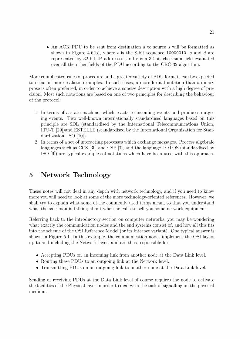
Referring back to the introductory section on computer networks, you may be wonderingwhat exactly the communication nodes and the end systems consist of, and how all this fitsinto the scheme of the OSI Reference Model (or its Internet variant). One typical answer isshown in Figure 5.1. In this example, the communication nodes implement the OSI layersup to and including the Network layer, and are thus responsible for:
• Accepting PDUs on an incoming link from another node at the Data Link level.
• Routing these PDUs to an outgoing link at the Network level.
• Transmitting PDUs on an outgoing link to another node at the Data Link level.
Sending or receiving PDUs at the Data Link level of course requires the node to activatethe facilities of the Physical layer in order to deal with the task of signalling on the physicalmedium.
22 5 NETWORK TECHNOLOGY
Medium
Communication nodesEnd systemA
End systemB
Ph
A
P
S
T
N
D
Ph
A
P
S
T
N
D
N
D
Ph
D
Ph
N
D
Ph
D
Ph
N
D
Ph
D
Ph
Figure 5.1: Layers in the communication nodes and end systems in a computer network
5.1 Routers
A node which implements the layers up to the Network layer and is capable of choosing asuitable route for sending an NPDU on to its destination is known as a router. Althoughthis cannot be seen in Figure 5.1, a router will in general have a larger number of linksto deal with than just two – otherwise there would be no need to make any choices aboutwhich route to take. You should refer back to Figure 3.3 for a view of the computer networkwhich should make this more clear.
When routing decisions have to be made, most routers are also able to decide that certainPDUs are not to be passed on to the destination which has been specified for them. Thisactivity of removing irrelevant PDUs is known as filtering. Typical reasons for doing thisinclude:
• The router can determine that the destination cannot be reached via any of theoutgoing links from the router.
• The router can determine that data from the given (or apparent) source is not desiredby the specified destination system.
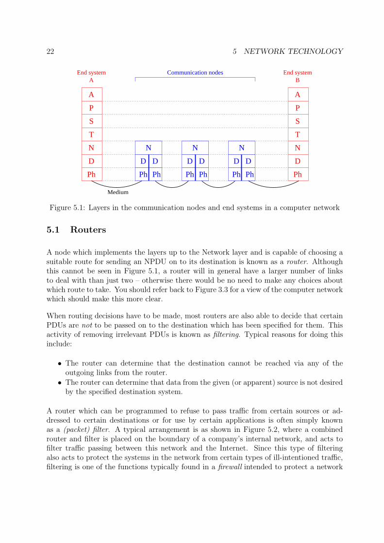
A router which can be programmed to refuse to pass traffic from certain sources or ad-dressed to certain destinations or for use by certain applications is often simply knownas a (packet) filter. A typical arrangement is as shown in Figure 5.2, where a combinedrouter and filter is placed on the boundary of a company’s internal network, and acts tofilter traffic passing between this network and the Internet. Since this type of filteringalso acts to protect the systems in the network from certain types of ill-intentioned traffic,filtering is one of the functions typically found in a firewall intended to protect a network
5.2 Bridges 23
To network B
To network C
Internal network
To network A
Internet
Router + Filter
Figure 5.2: A combined router and filter on the boundary between an internal network andthe Internet.
or subnet from attack by intruders such as hackers. Many modern routers in fact combinethe functions of a router and a firewall in the same piece of equipment.
5.2 Bridges
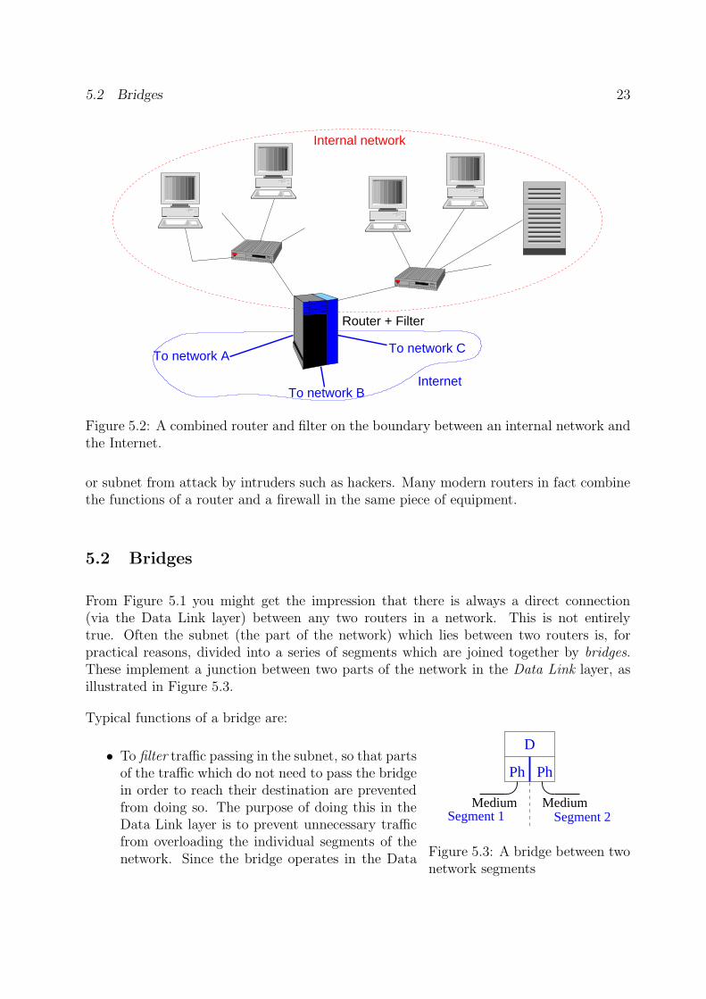
From Figure 5.1 you might get the impression that there is always a direct connection(via the Data Link layer) between any two routers in a network. This is not entirelytrue. Often the subnet (the part of the network) which lies between two routers is, forpractical reasons, divided into a series of segments which are joined together by bridges.These implement a junction between two parts of the network in the Data Link layer, asillustrated in Figure 5.3.
D
Ph Ph
Medium MediumSegment 1 Segment 2
Figure 5.3: A bridge between twonetwork segments
Typical functions of a bridge are:
• To filter traffic passing in the subnet, so that partsof the traffic which do not need to pass the bridgein order to reach their destination are preventedfrom doing so. The purpose of doing this in theData Link layer is to prevent unnecessary trafficfrom overloading the individual segments of thenetwork. Since the bridge operates in the Data
24 5 NETWORK TECHNOLOGY
Link layer, the filtering decision is based on theaddresses used to identify systems in this layer(rather than the Network addresses used by therouter).
• To adapt between different conventions for datatransmission used in the Physical layer in differ-ent segments which use the same Data Link pro-tocol (see Section 5.3 below). For example, onesegment may use electrical signalling on twistedpair cable, while the neighbouring segment uses afibre optic connection.
A bridge usually possesses no real routing capability – the kind of yes/no decisions madeby a filter do not qualify in this respect. However, a bridge will sometimes be a collectingpoint for several segments of a subnet, and in such a case it will also provide a rudimentaryform of routing, in order to pass data on to the appropriate segment.
5.3 LAN Technologies
A LAN is intended to offer data communication facilities over a limited area, such as asingle building, a company premises or an institution such as a university department oran entire university. Over such a limited area, it becomes technically feasible to let allthe nodes attached to the network have shared access to a common medium, which canbe based on cables or wireless facilities covering the area concerned. The Physical Layertechnologies are therefore chosen to suit such media, and the Data Link protocols controlaccess to the shared medium. Traditionally, the LAN Data Link layer is conceptuallydivided into two sub-layers:
1. A lower, technology-dependent Medium Access Control (MAC) sublayer, of which weshall look at two examples in detail below.
2. An upper Logical Link Control (LLC) sublayer, which is intended to provide atechnology-independent Data Link service based on a variety of MAC sublayers.
Most LAN MAC sublayers in current use follow one of the IEEE standards from the so-called 802.x series, which have been more or less taken over lock, stock and barrel by ISOto form the various parts of the ISO8802 standard. These are summarised in Table 5.1.You will notice that several numbers are missing in the table. Some of the missing itemscover general topics, such as LAN architecture (802.1), Logical Link Control (802.2) andsecurity (802.10); others have just never become standards. Many of the standards alsocome in several variants, for different Physical Layer data rates or different physical media(or both). We shall see some examples of this in the following sections.
5.3 LAN Technologies 25
IEEE ISO Technology
802.3 8802-3 Carrier Sense Multiple Access/Collision Detect (CSMA/CD)802.4 8802-4 Token Bus802.5 8802-5 Token Ring802.6 8802-6 Distributed Queue Dual Bus (DQDB)802.9 8802-9 Integrated Services (IS) LAN802.11 8802-11 Wireless LAN802.12 8802-12 Demand-priority Access802.15 8802-15 Wireless Personal Area Networks (WPAN)802.16 8802-16 Fixed Broadband Wireless Access (FBWA)
Table 5.1: IEEE and ISO standardised LAN technologies
5.3.1 CSMA/CD Technology
CSMA/CD technology is nowadays the dominant technology for wired LANs, i.e. local areanetworks where the signals are transmitted via some kind of cable which is laid out roundthe building(s) to be covered. Originally, the cable was a thick coaxial cable which couldcarry data at 10 Mbit/s; subsequently, thinner coaxial cables and shielded twisted pairs ofwires have been used, and data rates from 1 to 1000 Mbit/s have become readily available.The original technology was developed by a consortium of companies, and registered underthe trade name EthernetTM. This name is commonly (but not very correctly) used asa synonym for CSMA/CD, so for example the technology for operating CSMA/CD at1000 Mbit/s is often referred to as Gigabit Ethernet.
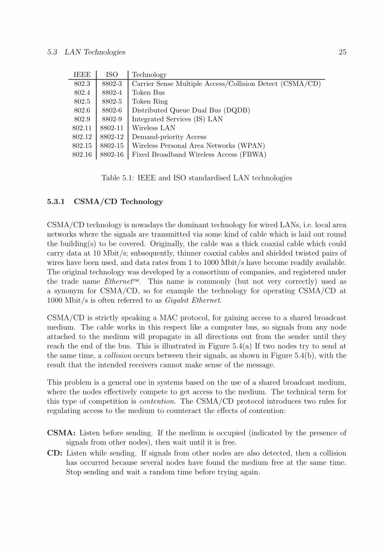
CSMA/CD is strictly speaking a MAC protocol, for gaining access to a shared broadcastmedium. The cable works in this respect like a computer bus, so signals from any nodeattached to the medium will propagate in all directions out from the sender until theyreach the end of the bus. This is illustrated in Figure 5.4(a) If two nodes try to send atthe same time, a collision occurs between their signals, as shown in Figure 5.4(b), with theresult that the intended receivers cannot make sense of the message.
This problem is a general one in systems based on the use of a shared broadcast medium,where the nodes effectively compete to get access to the medium. The technical term forthis type of competition is contention. The CSMA/CD protocol introduces two rules forregulating access to the medium to counteract the effects of contention:
CSMA: Listen before sending. If the medium is occupied (indicated by the presence ofsignals from other nodes), then wait until it is free.
CD: Listen while sending. If signals from other nodes are also detected, then a collisionhas occurred because several nodes have found the medium free at the same time.Stop sending and wait a random time before trying again.
26 5 NETWORK TECHNOLOGY
A B C D E F G
B C D E F GA
(a)
(b)
Figure 5.4: Propagation of signals along a shared bus or cable.
(a) Signals from a single sender (C) propagate along the bus in both directions.(b) If two nodes (C, F) try to send at the same time, their signals collide and
the transfer of data does not succeed.
when medium free
Randomretransmission delay
Randomretransmission delay
occupiedMedium
������������
��������������������
���������������������������������������
�����
�����
�����
������������������������
����������������������������
��������
�����
�����
������������
������������
����������������������
����������������������
����������������������
����������������������
����������������������
����������������������
���������������������������������
���������������������������������
���������������������������������
���������������������������������
Position
CE timeCD time
CD time CE time Transmission starts
Transmission startswhen medium free
Time
A
B
������������������������������������������
������������
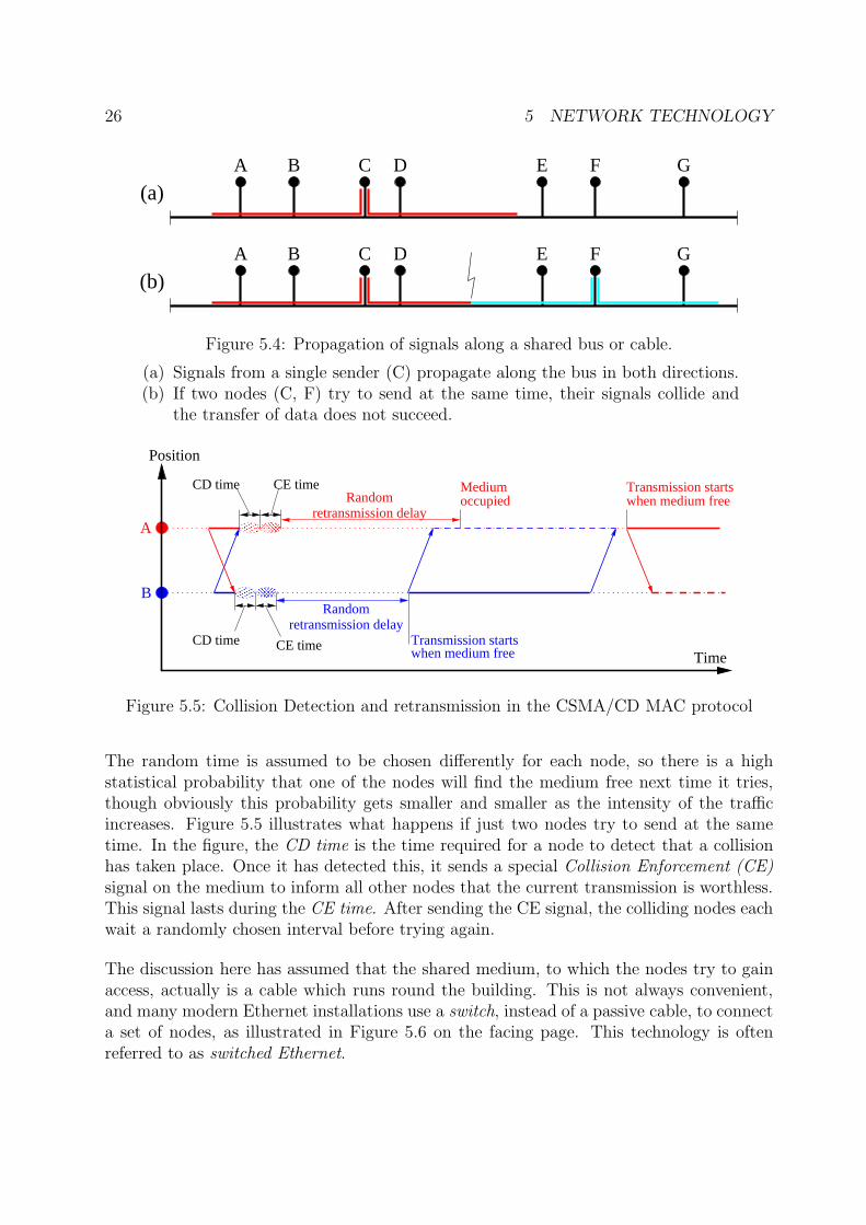
Figure 5.5: Collision Detection and retransmission in the CSMA/CD MAC protocol
The random time is assumed to be chosen differently for each node, so there is a highstatistical probability that one of the nodes will find the medium free next time it tries,though obviously this probability gets smaller and smaller as the intensity of the trafficincreases. Figure 5.5 illustrates what happens if just two nodes try to send at the sametime. In the figure, the CD time is the time required for a node to detect that a collisionhas taken place. Once it has detected this, it sends a special Collision Enforcement (CE)signal on the medium to inform all other nodes that the current transmission is worthless.This signal lasts during the CE time. After sending the CE signal, the colliding nodes eachwait a randomly chosen interval before trying again.
The discussion here has assumed that the shared medium, to which the nodes try to gainaccess, actually is a cable which runs round the building. This is not always convenient,and many modern Ethernet installations use a switch, instead of a passive cable, to connecta set of nodes, as illustrated in Figure 5.6 on the facing page. This technology is oftenreferred to as switched Ethernet.
5.3 LAN Technologies 27
Switch
A B C D EF GNodes
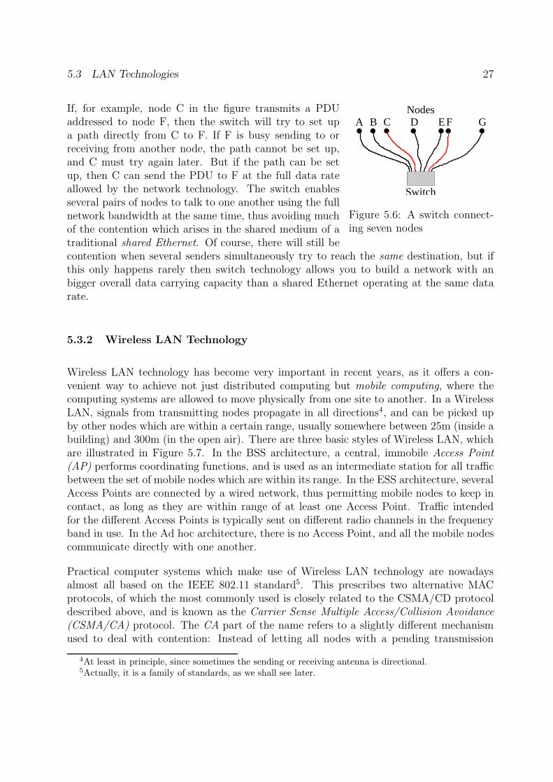
Figure 5.6: A switch connect-ing seven nodes
If, for example, node C in the figure transmits a PDUaddressed to node F, then the switch will try to set upa path directly from C to F. If F is busy sending to orreceiving from another node, the path cannot be set up,and C must try again later. But if the path can be setup, then C can send the PDU to F at the full data rateallowed by the network technology. The switch enablesseveral pairs of nodes to talk to one another using the fullnetwork bandwidth at the same time, thus avoiding muchof the contention which arises in the shared medium of atraditional shared Ethernet. Of course, there will still becontention when several senders simultaneously try to reach the same destination, but ifthis only happens rarely then switch technology allows you to build a network with anbigger overall data carrying capacity than a shared Ethernet operating at the same datarate.
5.3.2 Wireless LAN Technology
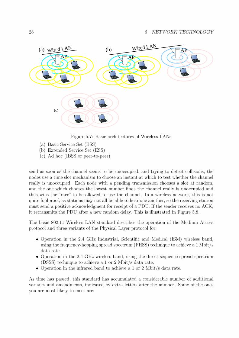
Wireless LAN technology has become very important in recent years, as it offers a con-venient way to achieve not just distributed computing but mobile computing, where thecomputing systems are allowed to move physically from one site to another. In a WirelessLAN, signals from transmitting nodes propagate in all directions4, and can be picked upby other nodes which are within a certain range, usually somewhere between 25m (inside abuilding) and 300m (in the open air). There are three basic styles of Wireless LAN, whichare illustrated in Figure 5.7. In the BSS architecture, a central, immobile Access Point(AP) performs coordinating functions, and is used as an intermediate station for all trafficbetween the set of mobile nodes which are within its range. In the ESS architecture, severalAccess Points are connected by a wired network, thus permitting mobile nodes to keep incontact, as long as they are within range of at least one Access Point. Traffic intendedfor the different Access Points is typically sent on different radio channels in the frequencyband in use. In the Ad hoc architecture, there is no Access Point, and all the mobile nodescommunicate directly with one another.
Practical computer systems which make use of Wireless LAN technology are nowadaysalmost all based on the IEEE 802.11 standard5. This prescribes two alternative MACprotocols, of which the most commonly used is closely related to the CSMA/CD protocoldescribed above, and is known as the Carrier Sense Multiple Access/Collision Avoidance(CSMA/CA) protocol. The CA part of the name refers to a slightly different mechanismused to deal with contention: Instead of letting all nodes with a pending transmission
4At least in principle, since sometimes the sending or receiving antenna is directional.5Actually, it is a family of standards, as we shall see later.
28 5 NETWORK TECHNOLOGY
(c)
(a) (b)Wired LAN Wired LAN
AP APAP
Figure 5.7: Basic architectures of Wireless LANs
(a) Basic Service Set (BSS)(b) Extended Service Set (ESS)(c) Ad hoc (IBSS or peer-to-peer)
send as soon as the channel seems to be unoccupied, and trying to detect collisions, thenodes use a time slot mechanism to choose an instant at which to test whether the channelreally is unoccupied. Each node with a pending transmission chooses a slot at random,and the one which chooses the lowest number finds the channel really is unoccupied andthus wins the “race” to be allowed to use the channel. In a wireless network, this is notquite foolproof, as stations may not all be able to hear one another, so the receiving stationmust send a positive acknowledgment for receipt of a PDU. If the sender receives no ACK,it retransmits the PDU after a new random delay. This is illustrated in Figure 5.8.
The basic 802.11 Wireless LAN standard describes the operation of the Medium Accessprotocol and three variants of the Physical Layer protocol for:
• Operation in the 2.4 GHz Industrial, Scientific and Medical (ISM) wireless band,using the frequency-hopping spread spectrum (FHSS) technique to achieve a 1 Mbit/sdata rate.
• Operation in the 2.4 GHz wireless band, using the direct sequence spread spectrum(DSSS) technique to achieve a 1 or 2 Mbit/s data rate.
• Operation in the infrared band to achieve a 1 or 2 Mbit/s data rate.
As time has passed, this standard has accumulated a considerable number of additionalvariants and amendments, indicated by extra letters after the number. Some of the onesyou are most likely to meet are:
5.3 LAN Technologies 29
occupiedMedium
��
����������������������������
�����������
���������������������
����������
����������
����������
�����������
�����������
�����������
�����������
�����������
�����������
Position
A
Time
B
C
if medium free
ACK
ACK
Transmission starts
Medium free.B’s transmission starts
during A’s chosen slot
Slot
9
Slot
0
Slot
1
Slot
2
Slot
4
Slot
3
IFS
������������������
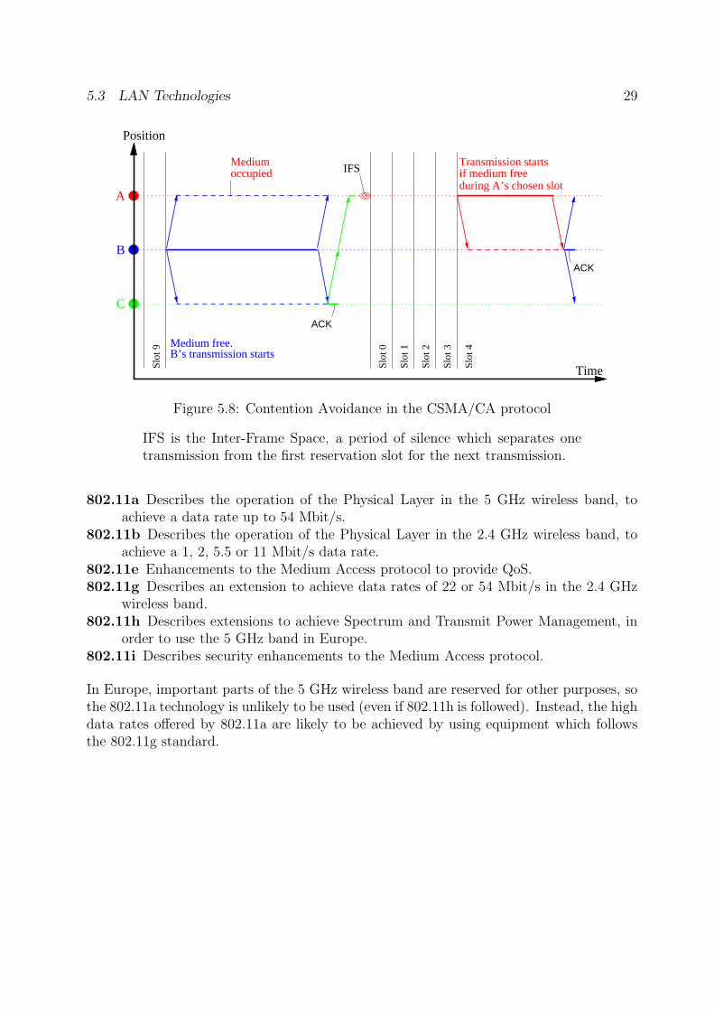
Figure 5.8: Contention Avoidance in the CSMA/CA protocol
IFS is the Inter-Frame Space, a period of silence which separates onetransmission from the first reservation slot for the next transmission.
802.11a Describes the operation of the Physical Layer in the 5 GHz wireless band, toachieve a data rate up to 54 Mbit/s.
802.11b Describes the operation of the Physical Layer in the 2.4 GHz wireless band, toachieve a 1, 2, 5.5 or 11 Mbit/s data rate.
802.11e Enhancements to the Medium Access protocol to provide QoS.802.11g Describes an extension to achieve data rates of 22 or 54 Mbit/s in the 2.4 GHz
wireless band.802.11h Describes extensions to achieve Spectrum and Transmit Power Management, in
order to use the 5 GHz band in Europe.802.11i Describes security enhancements to the Medium Access protocol.
In Europe, important parts of the 5 GHz wireless band are reserved for other purposes, sothe 802.11a technology is unlikely to be used (even if 802.11h is followed). Instead, the highdata rates offered by 802.11a are likely to be achieved by using equipment which followsthe 802.11g standard.
30 6 BASIC PROTOCOLS IN THE INTERNET
6 Basic Protocols in the Internet
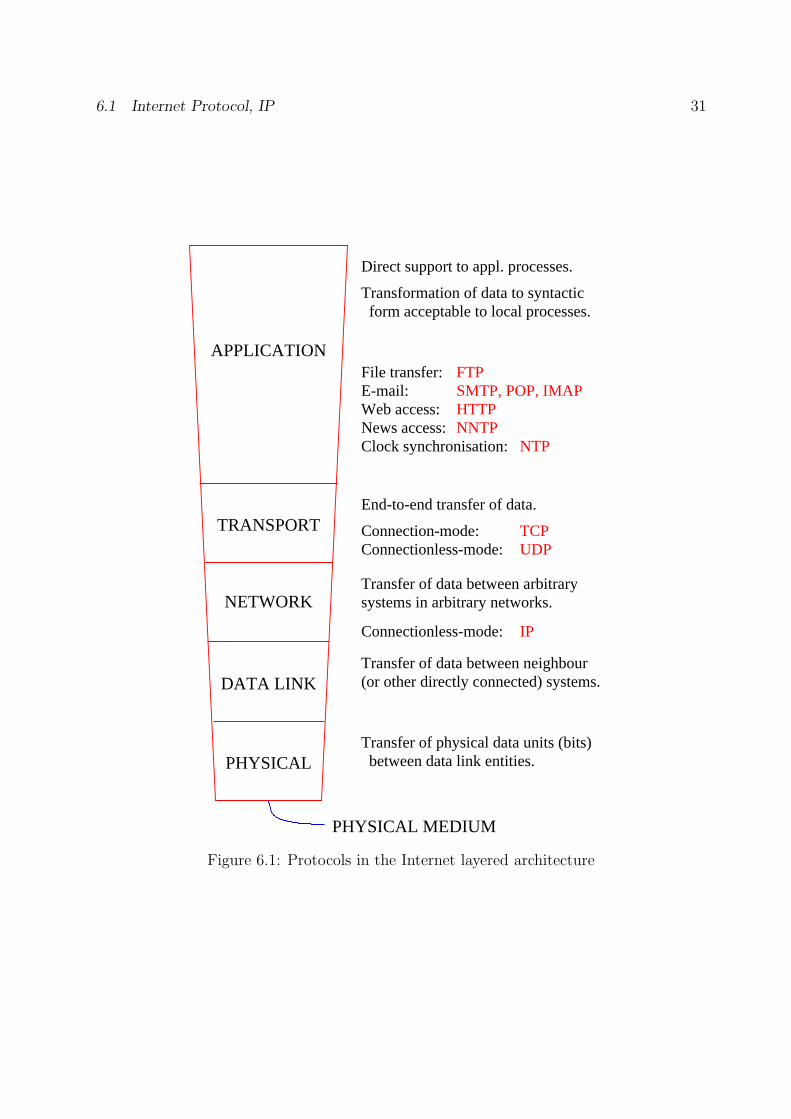
In these notes, most of the examples will be concerned with the kind of protocols usedin the Internet. An overview of some of the best known ones can be seen in Figure 6.1.There are no special Internet protocols assigned for use in the Data Link or Physicallayers. The protocols in these layers are very technology dependent, and the appropriatechoice will depend on the environment in which the network is to operate. For example,if communication takes place within a single building or building complex, it would benatural to base the network on LAN technology, and one of the IEEE 802.x protocolsdescribed in the previous section would be used in these layers. If communication is alsoto extend over a public WAN, an ITU-T protocol suite such as ATM would typically beused; in practice, the choice of protocol in a WAN will be made by the Internet ServiceProvider (ISP) who offers the IP service, and the user is unaware of what is going on inthe layers below the Network layer.
6.1 Internet Protocol, IP
IP is the basic Network layer protocol used in the Internet. The full name of the protocolmay cause you some confusion, since the word “internet” has two meanings: When speltwith a small “i” it refers to a type of protocol which is used to offer Network layer servicesover a set of interconnected subnets, possibly based on different technologies, while with alarge “I” it refers to the whole concept of the modern Internet. A more correct name forIP would really be “the Internet internet protocol”, but by now it is too late to change!
IP is a connectionless-mode protocol which is used to implement a connectionless-mode,full duplex, point-to-point or multicast stream service for data transfer. IP offers facilitiesfor segmentation and reassembly, and for various forms of routing. It is defined in twoversions:
1. “Classic” IP, often known as IPv4, which identifies the source and destination systemsby 32-bit addresses. This is described in the Internet document RFC791 which formspart of Internet Standard 5 [16].
2. Internet Protocol version 6, often just known as IPv6, which identifies source anddestination by 128-bit addresses and includes more comprehensive facilities for deal-ing with different classes of traffic, incorporating security, and other features. Theprotocol is described in RFC1883 [26], and the addressing scheme in RFC2373 [24].
Most current ISPs support IPv4, but a considerable international effort is currently goinginto the deployment of IPv6. An important reason for this is that the number of systemsattached to the Internet is increasing so rapidly that the supply of 32-bit addresses usedin IPv4 is running out.
6.1 Internet Protocol, IP 31
PHYSICAL MEDIUM
PHYSICAL
DATA LINK
NETWORK
TRANSPORT
Transfer of data between arbitrarysystems in arbitrary networks.
Transfer of data between neighbour(or other directly connected) systems.
Transfer of physical data units (bits) between data link entities.
Direct support to appl. processes.
APPLICATION
End-to-end transfer of data.
Transformation of data to syntactic form acceptable to local processes.
File transfer: E-mail: Web access:News access:Clock synchronisation:
FTP
HTTP
NTPNNTP
SMTP, POP, IMAP
Connection-mode:Connectionless-mode:
TCPUDP
Connectionless-mode: IP
Figure 6.1: Protocols in the Internet layered architecture
32 6 BASIC PROTOCOLS IN THE INTERNET
Bit
Version Type of service Total length
Fragment info.
Header checksum
Identification
Time−to−live Protocol
Source address
Destination address
Padding
Data (payload)
31150Headerlength
Header options
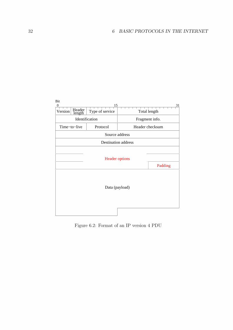
Figure 6.2: Format of an IP version 4 PDU
6.1 Internet Protocol, IP 33
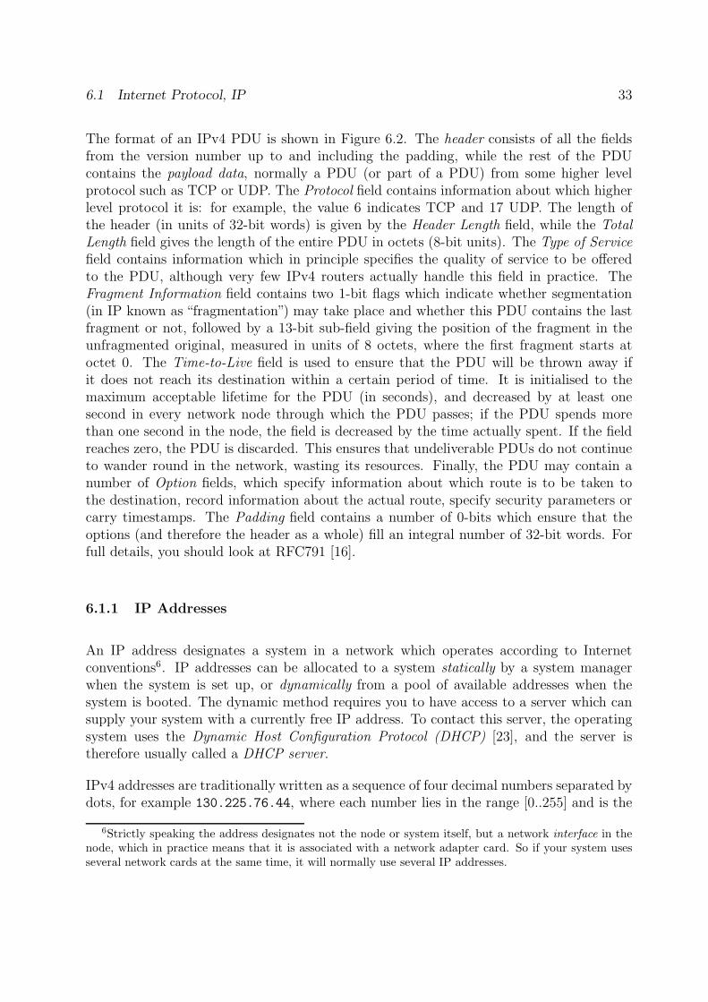
The format of an IPv4 PDU is shown in Figure 6.2. The header consists of all the fieldsfrom the version number up to and including the padding, while the rest of the PDUcontains the payload data, normally a PDU (or part of a PDU) from some higher levelprotocol such as TCP or UDP. The Protocol field contains information about which higherlevel protocol it is: for example, the value 6 indicates TCP and 17 UDP. The length ofthe header (in units of 32-bit words) is given by the Header Length field, while the TotalLength field gives the length of the entire PDU in octets (8-bit units). The Type of Servicefield contains information which in principle specifies the quality of service to be offeredto the PDU, although very few IPv4 routers actually handle this field in practice. TheFragment Information field contains two 1-bit flags which indicate whether segmentation(in IP known as “fragmentation”) may take place and whether this PDU contains the lastfragment or not, followed by a 13-bit sub-field giving the position of the fragment in theunfragmented original, measured in units of 8 octets, where the first fragment starts atoctet 0. The Time-to-Live field is used to ensure that the PDU will be thrown away ifit does not reach its destination within a certain period of time. It is initialised to themaximum acceptable lifetime for the PDU (in seconds), and decreased by at least onesecond in every network node through which the PDU passes; if the PDU spends morethan one second in the node, the field is decreased by the time actually spent. If the fieldreaches zero, the PDU is discarded. This ensures that undeliverable PDUs do not continueto wander round in the network, wasting its resources. Finally, the PDU may contain anumber of Option fields, which specify information about which route is to be taken tothe destination, record information about the actual route, specify security parameters orcarry timestamps. The Padding field contains a number of 0-bits which ensure that theoptions (and therefore the header as a whole) fill an integral number of 32-bit words. Forfull details, you should look at RFC791 [16].
6.1.1 IP Addresses
An IP address designates a system in a network which operates according to Internetconventions6. IP addresses can be allocated to a system statically by a system managerwhen the system is set up, or dynamically from a pool of available addresses when thesystem is booted. The dynamic method requires you to have access to a server which cansupply your system with a currently free IP address. To contact this server, the operatingsystem uses the Dynamic Host Configuration Protocol (DHCP) [23], and the server istherefore usually called a DHCP server.
IPv4 addresses are traditionally written as a sequence of four decimal numbers separated bydots, for example 130.225.76.44, where each number lies in the range [0..255] and is the
6Strictly speaking the address designates not the node or system itself, but a network interface in thenode, which in practice means that it is associated with a network adapter card. So if your system usesseveral network cards at the same time, it will normally use several IP addresses.
34 6 BASIC PROTOCOLS IN THE INTERNET
Addressclass
Private Network addresses
IPv4 address classes
1−127 0−255 0−255
128−191 0−255 0−255
192−223 0−255 0−255
0−255
0−255
0−255
224−239 0−255 0−255 0−255
Host idNetwork id
Multicast group id
0−255 0−255
0−255 0−255
0−255 0−255
0−25510
172 16−31
192 168
h h h h h h h h h h h h h h h h h h h h h h h h
h h h h h h h h h h h h h h h h
h h h h h h h h
A
B
C
h h h h h h h h h h h h h h h h h h h h h h h h
h h h h h h h h h h h h h h h h
h h h h h h h h
Multi−cast
A
B
C
n n n n n n n n
n n n n n n n n n n n n n n n n
0
1
1 1 0
0
n n n n n n n
n n n n n n
n n n n n
n n n n n n n n
1 1 1 0
0
1
1 1 0
0
0 0 0 10 01
1 1 10 0 0 n n n n0 0 0 1
0 0 0 0 0 1 0 1 0 1 0 0 0
Figure 6.3: IPv4 addresses (above) and Private Network addresses (below)
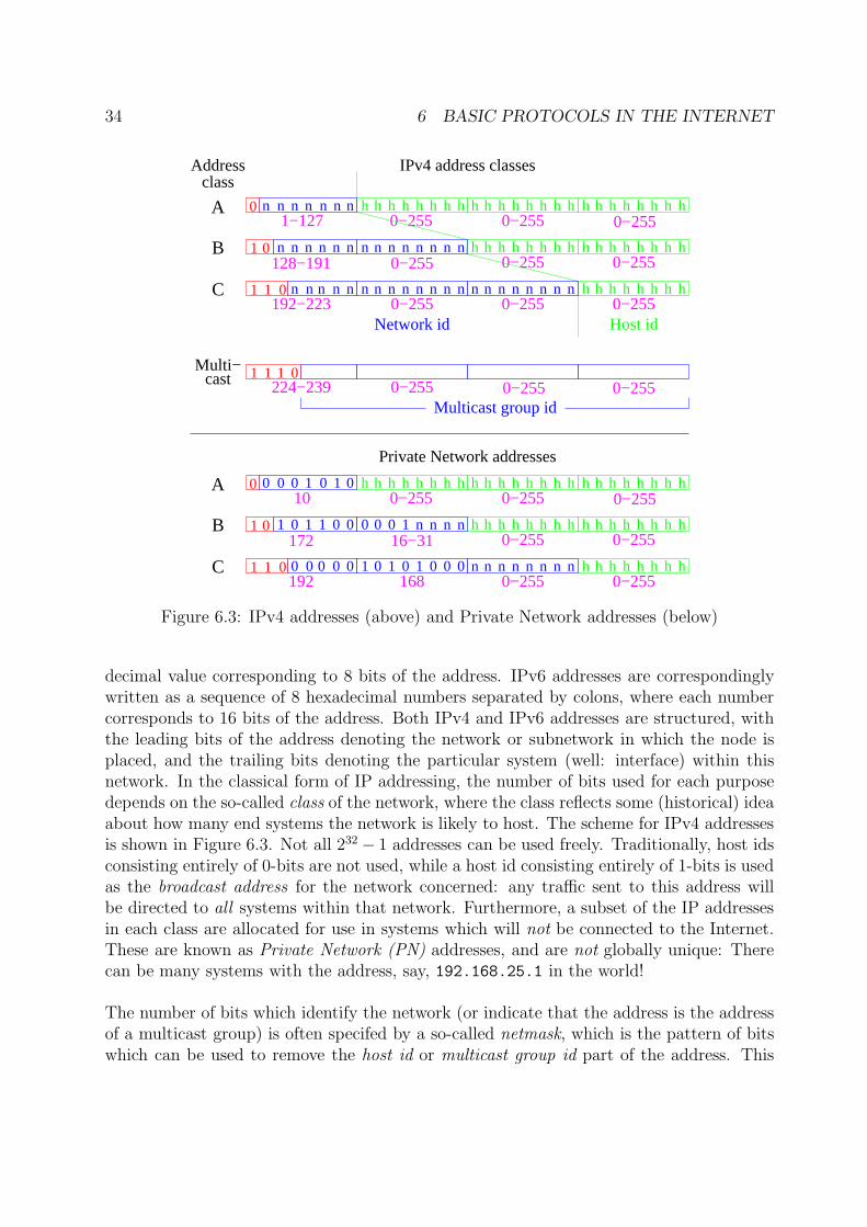
decimal value corresponding to 8 bits of the address. IPv6 addresses are correspondinglywritten as a sequence of 8 hexadecimal numbers separated by colons, where each numbercorresponds to 16 bits of the address. Both IPv4 and IPv6 addresses are structured, withthe leading bits of the address denoting the network or subnetwork in which the node isplaced, and the trailing bits denoting the particular system (well: interface) within thisnetwork. In the classical form of IP addressing, the number of bits used for each purposedepends on the so-called class of the network, where the class reflects some (historical) ideaabout how many end systems the network is likely to host. The scheme for IPv4 addressesis shown in Figure 6.3. Not all 232 − 1 addresses can be used freely. Traditionally, host idsconsisting entirely of 0-bits are not used, while a host id consisting entirely of 1-bits is usedas the broadcast address for the network concerned: any traffic sent to this address willbe directed to all systems within that network. Furthermore, a subset of the IP addressesin each class are allocated for use in systems which will not be connected to the Internet.These are known as Private Network (PN) addresses, and are not globally unique: Therecan be many systems with the address, say, 192.168.25.1 in the world!
The number of bits which identify the network (or indicate that the address is the addressof a multicast group) is often specifed by a so-called netmask, which is the pattern of bitswhich can be used to remove the host id or multicast group id part of the address. This
6.1 Internet Protocol, IP 35
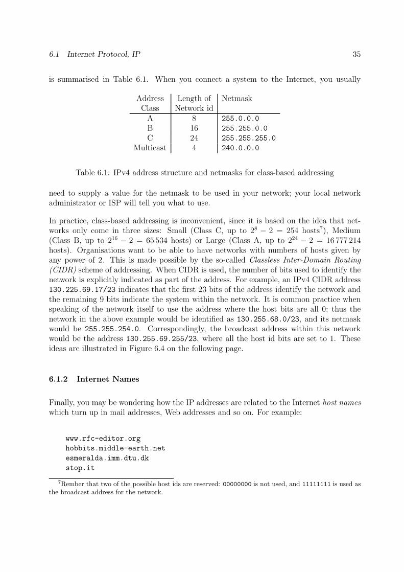
is summarised in Table 6.1. When you connect a system to the Internet, you usually
Address Length of NetmaskClass Network id
A 8 255.0.0.0
B 16 255.255.0.0
C 24 255.255.255.0
Multicast 4 240.0.0.0
Table 6.1: IPv4 address structure and netmasks for class-based addressing
need to supply a value for the netmask to be used in your network; your local networkadministrator or ISP will tell you what to use.
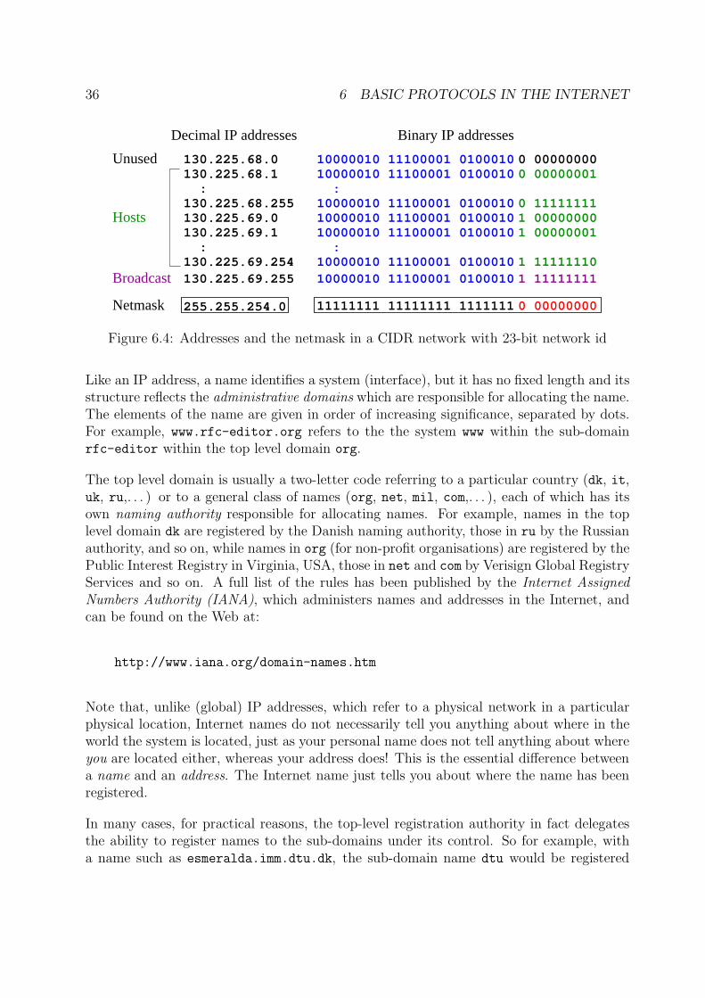
In practice, class-based addressing is inconvenient, since it is based on the idea that net-works only come in three sizes: Small (Class C, up to 28 − 2 = 254 hosts7), Medium(Class B, up to 216 − 2 = 65 534 hosts) or Large (Class A, up to 224 − 2 = 16 777 214hosts). Organisations want to be able to have networks with numbers of hosts given byany power of 2. This is made possible by the so-called Classless Inter-Domain Routing(CIDR) scheme of addressing. When CIDR is used, the number of bits used to identify thenetwork is explicitly indicated as part of the address. For example, an IPv4 CIDR address130.225.69.17/23 indicates that the first 23 bits of the address identify the network andthe remaining 9 bits indicate the system within the network. It is common practice whenspeaking of the network itself to use the address where the host bits are all 0; thus thenetwork in the above example would be identified as 130.255.68.0/23, and its netmaskwould be 255.255.254.0. Correspondingly, the broadcast address within this networkwould be the address 130.255.69.255/23, where all the host id bits are set to 1. Theseideas are illustrated in Figure 6.4 on the following page.
6.1.2 Internet Names
Finally, you may be wondering how the IP addresses are related to the Internet host nameswhich turn up in mail addresses, Web addresses and so on. For example:
www.rfc-editor.org
hobbits.middle-earth.net
esmeralda.imm.dtu.dk
stop.it
7Rember that two of the possible host ids are reserved: 00000000 is not used, and 11111111 is used asthe broadcast address for the network.
36 6 BASIC PROTOCOLS IN THE INTERNET
11111111 11111111 1111111
Broadcast
Hosts
Unused
Decimal IP addresses Binary IP addresses
:
:
10000010 11100001 0100010
10000010 11100001 010001010000010 11100001 010001010000010 11100001 0100010
10000010 11100001 01000100 00000001
0 111111111 000000001 00000001
130.225.68.0130.225.68.1 :130.225.68.255130.225.69.0130.225.69.1 :
10000010 11100001 0100010130.225.69.25510000010 11100001 0100010 1 11111110130.225.69.254
1 11111111
0 00000000
0 00000000255.255.254.0Netmask
Figure 6.4: Addresses and the netmask in a CIDR network with 23-bit network id
Like an IP address, a name identifies a system (interface), but it has no fixed length and itsstructure reflects the administrative domains which are responsible for allocating the name.The elements of the name are given in order of increasing significance, separated by dots.For example, www.rfc-editor.org refers to the the system www within the sub-domainrfc-editor within the top level domain org.
The top level domain is usually a two-letter code referring to a particular country (dk, it,uk, ru,. . . ) or to a general class of names (org, net, mil, com,. . . ), each of which has itsown naming authority responsible for allocating names. For example, names in the toplevel domain dk are registered by the Danish naming authority, those in ru by the Russianauthority, and so on, while names in org (for non-profit organisations) are registered by thePublic Interest Registry in Virginia, USA, those in net and com by Verisign Global RegistryServices and so on. A full list of the rules has been published by the Internet AssignedNumbers Authority (IANA), which administers names and addresses in the Internet, andcan be found on the Web at:
http://www.iana.org/domain-names.htm
Note that, unlike (global) IP addresses, which refer to a physical network in a particularphysical location, Internet names do not necessarily tell you anything about where in theworld the system is located, just as your personal name does not tell anything about whereyou are located either, whereas your address does! This is the essential difference betweena name and an address. The Internet name just tells you about where the name has beenregistered.
In many cases, for practical reasons, the top-level registration authority in fact delegatesthe ability to register names to the sub-domains under its control. So for example, witha name such as esmeralda.imm.dtu.dk, the sub-domain name dtu would be registered
6.2 Transmission Control Protocol, TCP 37
IPs IPd2580110123 NTP
POP3HTTPSMTP
7496
Ass
igne
d to
Ports
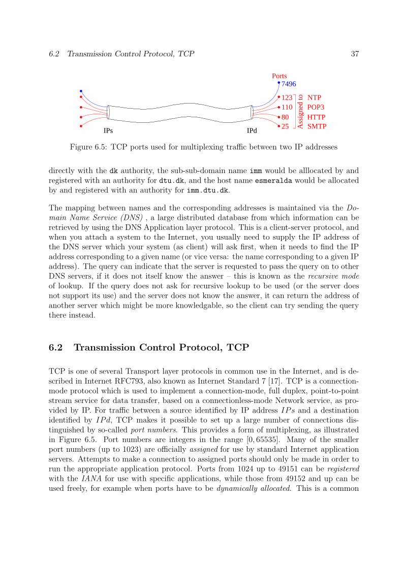
Figure 6.5: TCP ports used for multiplexing traffic between two IP addresses
directly with the dk authority, the sub-sub-domain name imm would be alllocated by andregistered with an authority for dtu.dk, and the host name esmeralda would be allocatedby and registered with an authority for imm.dtu.dk.
The mapping between names and the corresponding addresses is maintained via the Do-main Name Service (DNS) , a large distributed database from which information can beretrieved by using the DNS Application layer protocol. This is a client-server protocol, andwhen you attach a system to the Internet, you usually need to supply the IP address ofthe DNS server which your system (as client) will ask first, when it needs to find the IPaddress corresponding to a given name (or vice versa: the name corresponding to a given IPaddress). The query can indicate that the server is requested to pass the query on to otherDNS servers, if it does not itself know the answer – this is known as the recursive modeof lookup. If the query does not ask for recursive lookup to be used (or the server doesnot support its use) and the server does not know the answer, it can return the address ofanother server which might be more knowledgable, so the client can try sending the querythere instead.
6.2 Transmission Control Protocol, TCP
TCP is one of several Transport layer protocols in common use in the Internet, and is de-scribed in Internet RFC793, also known as Internet Standard 7 [17]. TCP is a connection-mode protocol which is used to implement a connection-mode, full duplex, point-to-pointstream service for data transfer, based on a connectionless-mode Network service, as pro-vided by IP. For traffic between a source identified by IP address IPs and a destinationidentified by IPd, TCP makes it possible to set up a large number of connections dis-tinguished by so-called port numbers. This provides a form of multiplexing, as illustratedin Figure 6.5. Port numbers are integers in the range [0, 65535]. Many of the smallerport numbers (up to 1023) are officially assigned for use by standard Internet applicationservers. Attempts to make a connection to assigned ports should only be made in order torun the appropriate application protocol. Ports from 1024 up to 49151 can be registeredwith the IANA for use with specific applications, while those from 49152 and up can beused freely, for example when ports have to be dynamically allocated. This is a common
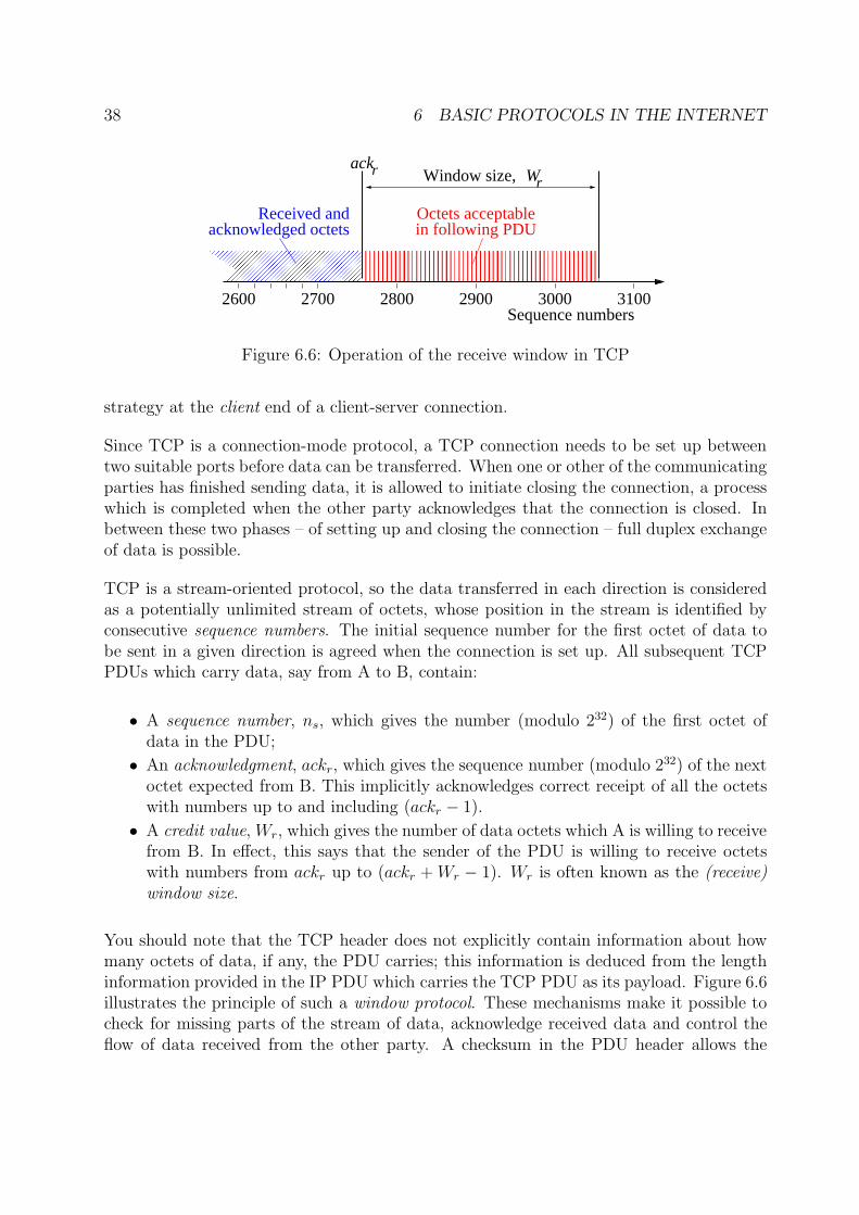
38 6 BASIC PROTOCOLS IN THE INTERNET
������������������������������
������������������������������
������������������������������������������������������������������������������������
������������������������������������������������������������������������������������
in following PDUOctets acceptable
ackr Wr����������������������������Window size,
����
����
2600Sequence numbers
2700 2800 2900 3000 3100
Received andacknowledged octets
Figure 6.6: Operation of the receive window in TCP
strategy at the client end of a client-server connection.
Since TCP is a connection-mode protocol, a TCP connection needs to be set up betweentwo suitable ports before data can be transferred. When one or other of the communicatingparties has finished sending data, it is allowed to initiate closing the connection, a processwhich is completed when the other party acknowledges that the connection is closed. Inbetween these two phases – of setting up and closing the connection – full duplex exchangeof data is possible.
TCP is a stream-oriented protocol, so the data transferred in each direction is consideredas a potentially unlimited stream of octets, whose position in the stream is identified byconsecutive sequence numbers. The initial sequence number for the first octet of data tobe sent in a given direction is agreed when the connection is set up. All subsequent TCPPDUs which carry data, say from A to B, contain:
• A sequence number, ns, which gives the number (modulo 232) of the first octet ofdata in the PDU;
• An acknowledgment, ackr, which gives the sequence number (modulo 232) of the nextoctet expected from B. This implicitly acknowledges correct receipt of all the octetswith numbers up to and including (ackr − 1).
• A credit value, Wr, which gives the number of data octets which A is willing to receivefrom B. In effect, this says that the sender of the PDU is willing to receive octetswith numbers from ackr up to (ackr + Wr − 1). Wr is often known as the (receive)window size.
You should note that the TCP header does not explicitly contain information about howmany octets of data, if any, the PDU carries; this information is deduced from the lengthinformation provided in the IP PDU which carries the TCP PDU as its payload. Figure 6.6illustrates the principle of such a window protocol. These mechanisms make it possible tocheck for missing parts of the stream of data, acknowledge received data and control theflow of data received from the other party. A checksum in the PDU header allows the
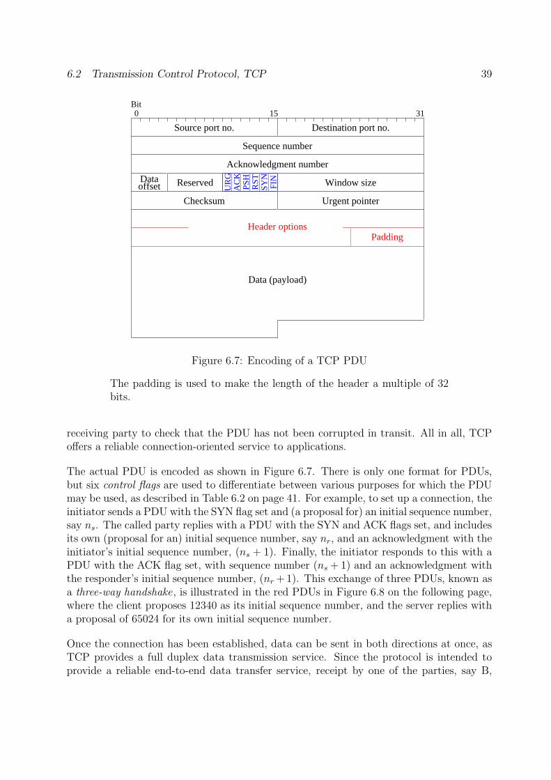
6.2 Transmission Control Protocol, TCP 39
UR
GA
CK
PSH
RST
SYN
FIN
Bit
Sequence number
Acknowledgment number
Checksum Urgent pointer
Window sizeDataoffset Reserved
Padding
Source port no. Destination port no.
0 3115
Data (payload)
Header options
Figure 6.7: Encoding of a TCP PDU
The padding is used to make the length of the header a multiple of 32bits.
receiving party to check that the PDU has not been corrupted in transit. All in all, TCPoffers a reliable connection-oriented service to applications.
The actual PDU is encoded as shown in Figure 6.7. There is only one format for PDUs,but six control flags are used to differentiate between various purposes for which the PDUmay be used, as described in Table 6.2 on page 41. For example, to set up a connection, theinitiator sends a PDU with the SYN flag set and (a proposal for) an initial sequence number,say ns. The called party replies with a PDU with the SYN and ACK flags set, and includesits own (proposal for an) initial sequence number, say nr, and an acknowledgment with theinitiator’s initial sequence number, (ns + 1). Finally, the initiator responds to this with aPDU with the ACK flag set, with sequence number (ns + 1) and an acknowledgment withthe responder’s initial sequence number, (nr +1). This exchange of three PDUs, known asa three-way handshake, is illustrated in the red PDUs in Figure 6.8 on the following page,where the client proposes 12340 as its initial sequence number, and the server replies witha proposal of 65024 for its own initial sequence number.
Once the connection has been established, data can be sent in both directions at once, asTCP provides a full duplex data transmission service. Since the protocol is intended toprovide a reliable end-to-end data transfer service, receipt by one of the parties, say B,
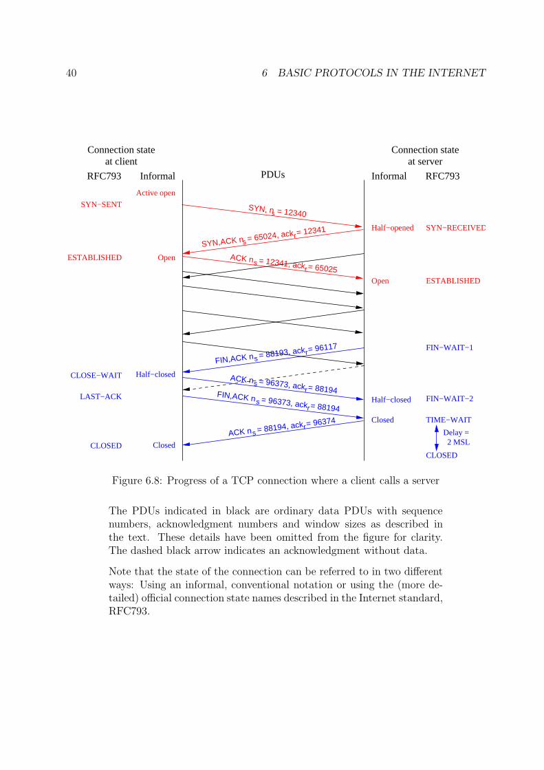
40 6 BASIC PROTOCOLS IN THE INTERNET
= 12340
SYN,ACK n = 65024, ackrs
= 12341
= 12341, ackrs = 65025
ACK n
Connection stateat client
Connection stateat server
= 88193, ackrs
= 96117
FIN,ACK n
= 96373, ackrs = 88194
ACK n
= 96373, ackrs = 88194
FIN,ACK n
= 88194, ackrs
= 96374
ACK n Delay = 2 MSL
Half−opened
Open
Open
Half−closed
Closed
Half−closed
Closed
SYN−RECEIVED
ESTABLISHED
FIN−WAIT−1
FIN−WAIT−2
SYN−SENT
Active open
ESTABLISHED
CLOSE−WAIT
LAST−ACK
CLOSED
PDUsRFC793 Informal Informal RFC793
TIME−WAIT
SYN, n
CLOSED
s
Figure 6.8: Progress of a TCP connection where a client calls a server
The PDUs indicated in black are ordinary data PDUs with sequencenumbers, acknowledgment numbers and window sizes as described inthe text. These details have been omitted from the figure for clarity.The dashed black arrow indicates an acknowledgment without data.
Note that the state of the connection can be referred to in two differentways: Using an informal, conventional notation or using the (more de-tailed) official connection state names described in the Internet standard,RFC793.
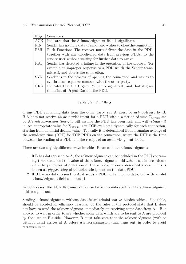
6.2 Transmission Control Protocol, TCP 41
Flag SemanticsACK Indicates that the Acknowledgement field is significant.FIN Sender has no more data to send, and wishes to close the connection.PSH Push Function: The receiver must deliver the data in the PDU,
together with any undelivered data from previous PDUs, to theservice user without waiting for further data to arrive.
RST Sender has detected a failure in the operation of the protocol (forexample an improper response to a PDU which the Sender trans-mitted), and aborts the connection.
SYN Sender is in the process of opening the connection and wishes tosynchronise sequence numbers with the other party.
URG Indicates that the Urgent Pointer is significant, and that it givesthe offset of Urgent Data in the PDU.
Table 6.2: TCP flags
of any PDU containing data from the other party, say A, must be acknowledged by B.If A does not receive an acknowledgment for a PDU within a period of time Tretrans setby A’s retransmission timer, it will assume the PDU has been lost, and will retransmitit. An appropriate value for Tretrans is in TCP evaluated dynamically for each connection,starting from an initial default value. Typically it is determined from a running average ofthe round-trip time (RTT) for TCP PDUs on the connection, where the RTT is the timebetween the sending of a PDU and the receipt of an acknowledgment for it.
There are two slightly different ways in which B can send an acknowledgment:
1. If B has data to send to A, the acknowledgment can be included in the PDU contain-ing these data, and the value of the acknowledgment field ackr is set in accordancewith the principles of operation of the window protocol described above. This isknown as piggybacking of the acknowledgment on the data PDU.
2. If B has no data to send to A, it sends a PDU containing no data, but with a validacknowledgment field as in case 1.
In both cases, the ACK flag must of course be set to indicate that the acknowledgmentfield is significant.
Sending acknowledgments without data is an administrative burden which, if possible,should be avoided for efficiency reasons. So the rules of the protocol state that B doesnot have to send the acknowledgment immediately on receiving some data from A – B isallowed to wait in order to see whether some data which are to be sent to A are providedby the user on B’s side. However, B must take care that the acknowledgment (with orwithout data) arrives at A before A’s retransmission timer runs out, in order to avoidretransmission.
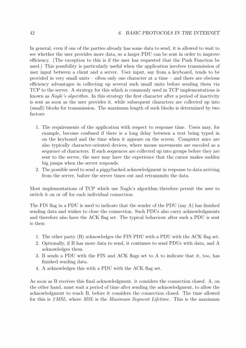
42 6 BASIC PROTOCOLS IN THE INTERNET
In general, even if one of the parties already has some data to send, it is allowed to wait tosee whether the user provides more data, so a larger PDU can be sent in order to improveefficiency. (The exception to this is if the user has requested that the Push Function beused.) This possibility is particularly useful when the application involves transmission ofuser input between a client and a server. User input, say from a keyboard, tends to beprovided in very small units – often only one character at a time – and there are obviousefficiency advantages in collecting up several such small units before sending them viaTCP to the server. A strategy for this which is commonly used in TCP implementations isknown as Nagle’s algorithm. In this strategy the first character after a period of inactivityis sent as soon as the user provides it, while subsequent characters are collected up into(small) blocks for transmission. The maximum length of such blocks is determined by twofactors:
1. The requirements of the application with respect to response time. Users may, forexample, become confused if there is a long delay between a text being typed inon the keyboard and the time when it appears on the screen. Computer mice arealso typically character-oriented devices, where mouse movements are encoded as asequence of characters. If such sequences are collected up into groups before they aresent to the server, the user may have the experience that the cursor makes suddenbig jumps when the server responds.
2. The possible need to send a piggybacked acknowledgment in response to data arrivingfrom the server, bafore the server times out and retransmits the data.
Most implementations of TCP which use Nagle’s algorithm therefore permit the user toswitch it on or off for each individual connection.
The FIN flag in a PDU is used to indicate that the sender of the PDU (say A) has finishedsending data and wishes to close the connection. Such PDUs also carry acknowledgmentsand therefore also have the ACK flag set. The typical behaviour after such a PDU is sentis then:
1. The other party (B) acknowledges the FIN PDU with a PDU with the ACK flag set.
2. Optionally, if B has more data to send, it continues to send PDUs with data, and Aacknowledges them.
3. B sends a PDU with the FIN and ACK flags set to A to indicate that it, too, hasfinished sending data.
4. A acknowledges this with a PDU with the ACK flag set.
As soon as B receives this final acknowledgment, it considers the connection closed. A, onthe other hand, must wait a period of time after sending the acknowledgment, to allow theacknowledgment to reach B, before it considers the connection closed. The time allowedfor this is 2MSL, where MSL is the Maximum Segment Lifetime. This is the maximum
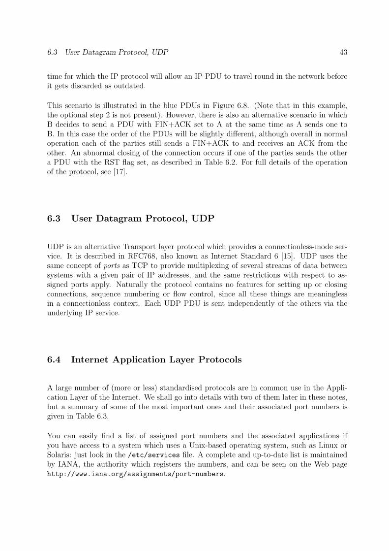
6.3 User Datagram Protocol, UDP 43
time for which the IP protocol will allow an IP PDU to travel round in the network beforeit gets discarded as outdated.
This scenario is illustrated in the blue PDUs in Figure 6.8. (Note that in this example,the optional step 2 is not present). However, there is also an alternative scenario in whichB decides to send a PDU with FIN+ACK set to A at the same time as A sends one toB. In this case the order of the PDUs will be slightly different, although overall in normaloperation each of the parties still sends a FIN+ACK to and receives an ACK from theother. An abnormal closing of the connection occurs if one of the parties sends the othera PDU with the RST flag set, as described in Table 6.2. For full details of the operationof the protocol, see [17].
6.3 User Datagram Protocol, UDP
UDP is an alternative Transport layer protocol which provides a connectionless-mode ser-vice. It is described in RFC768, also known as Internet Standard 6 [15]. UDP uses thesame concept of ports as TCP to provide multiplexing of several streams of data betweensystems with a given pair of IP addresses, and the same restrictions with respect to as-signed ports apply. Naturally the protocol contains no features for setting up or closingconnections, sequence numbering or flow control, since all these things are meaninglessin a connectionless context. Each UDP PDU is sent independently of the others via theunderlying IP service.
6.4 Internet Application Layer Protocols
A large number of (more or less) standardised protocols are in common use in the Appli-cation Layer of the Internet. We shall go into details with two of them later in these notes,but a summary of some of the most important ones and their associated port numbers isgiven in Table 6.3.
You can easily find a list of assigned port numbers and the associated applications ifyou have access to a system which uses a Unix-based operating system, such as Linux orSolaris: just look in the /etc/services file. A complete and up-to-date list is maintainedby IANA, the authority which registers the numbers, and can be seen on the Web pagehttp://www.iana.org/assignments/port-numbers.
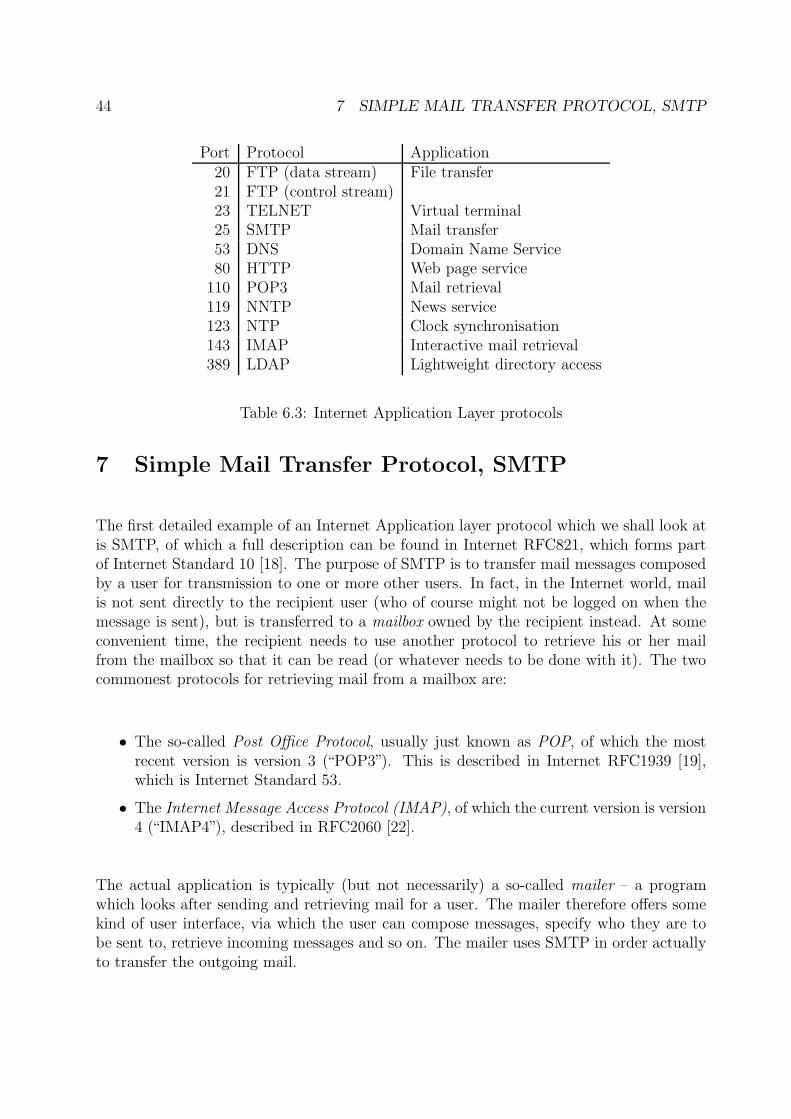
44 7 SIMPLE MAIL TRANSFER PROTOCOL, SMTP
Port Protocol Application20 FTP (data stream) File transfer21 FTP (control stream)23 TELNET Virtual terminal25 SMTP Mail transfer53 DNS Domain Name Service80 HTTP Web page service
110 POP3 Mail retrieval119 NNTP News service123 NTP Clock synchronisation143 IMAP Interactive mail retrieval389 LDAP Lightweight directory access
Table 6.3: Internet Application Layer protocols
7 Simple Mail Transfer Protocol, SMTP
The first detailed example of an Internet Application layer protocol which we shall look atis SMTP, of which a full description can be found in Internet RFC821, which forms partof Internet Standard 10 [18]. The purpose of SMTP is to transfer mail messages composedby a user for transmission to one or more other users. In fact, in the Internet world, mailis not sent directly to the recipient user (who of course might not be logged on when themessage is sent), but is transferred to a mailbox owned by the recipient instead. At someconvenient time, the recipient needs to use another protocol to retrieve his or her mailfrom the mailbox so that it can be read (or whatever needs to be done with it). The twocommonest protocols for retrieving mail from a mailbox are:
• The so-called Post Office Protocol, usually just known as POP, of which the mostrecent version is version 3 (“POP3”). This is described in Internet RFC1939 [19],which is Internet Standard 53.
• The Internet Message Access Protocol (IMAP), of which the current version is version4 (“IMAP4”), described in RFC2060 [22].
The actual application is typically (but not necessarily) a so-called mailer – a programwhich looks after sending and retrieving mail for a user. The mailer therefore offers somekind of user interface, via which the user can compose messages, specify who they are tobe sent to, retrieve incoming messages and so on. The mailer uses SMTP in order actuallyto transfer the outgoing mail.
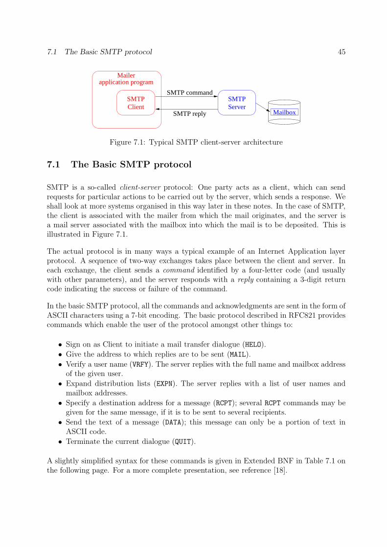
7.1 The Basic SMTP protocol 45
SMTPClient
SMTPServer
Mailbox
SMTP command
SMTP reply
Mailerapplication program
Figure 7.1: Typical SMTP client-server architecture
7.1 The Basic SMTP protocol
SMTP is a so-called client-server protocol: One party acts as a client, which can sendrequests for particular actions to be carried out by the server, which sends a response. Weshall look at more systems organised in this way later in these notes. In the case of SMTP,the client is associated with the mailer from which the mail originates, and the server isa mail server associated with the mailbox into which the mail is to be deposited. This isillustrated in Figure 7.1.
The actual protocol is in many ways a typical example of an Internet Application layerprotocol. A sequence of two-way exchanges takes place between the client and server. Ineach exchange, the client sends a command identified by a four-letter code (and usuallywith other parameters), and the server responds with a reply containing a 3-digit returncode indicating the success or failure of the command.
In the basic SMTP protocol, all the commands and acknowledgments are sent in the form ofASCII characters using a 7-bit encoding. The basic protocol described in RFC821 providescommands which enable the user of the protocol amongst other things to:
• Sign on as Client to initiate a mail transfer dialogue (HELO).
• Give the address to which replies are to be sent (MAIL).
• Verify a user name (VRFY). The server replies with the full name and mailbox addressof the given user.
• Expand distribution lists (EXPN). The server replies with a list of user names andmailbox addresses.
• Specify a destination address for a message (RCPT); several RCPT commands may begiven for the same message, if it is to be sent to several recipients.
• Send the text of a message (DATA); this message can only be a portion of text inASCII code.
• Terminate the current dialogue (QUIT).
A slightly simplified syntax for these commands is given in Extended BNF in Table 7.1 onthe following page. For a more complete presentation, see reference [18].
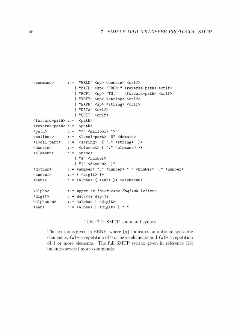
46 7 SIMPLE MAIL TRANSFER PROTOCOL, SMTP
<command> ::= "HELO" <sp> <domain> <crlf>
| "MAIL" <sp> "FROM:" <reverse-path> <crlf>
| "RCPT" <sp> "TO:" <forward-path> <crlf>
| "VRFY" <sp> <string> <crlf>
| "EXPN" <sp> <string> <crlf>
| "DATA" <crlf>
| "QUIT" <crlf>
<forward-path> ::= <path>
<reverse-path> ::= <path>
<path> ::= "<" <mailbox> ">"
<mailbox> ::= <local-part> "@" <domain>
<local-part> ::= <string> { "." <string> }*
<domain> ::= <element> { "." <element> }*
<element> ::= <name>
| "#" <number>
| "[" <dotnum> "]"
<dotnum> ::= <number> "." <number> "." <number> "." <number>
<number> ::= { <digit> }+
<name> ::= <alpha> { <anh> }* <alphanum>
<alpha> ::= upper or lower case English letters
<digit> ::= decimal digits
<alphanum> ::= <alpha> | <digit>
<anh> ::= <alpha> | <digit> | "-"
Table 7.1: SMTP command syntax
The syntax is given in EBNF, where [x] indicates an optional syntacticelement x, {x}* a repetition of 0 or more elements and {x}+ a repetitionof 1 or more elements. The full SMTP syntax given in reference [18]includes several more commands.
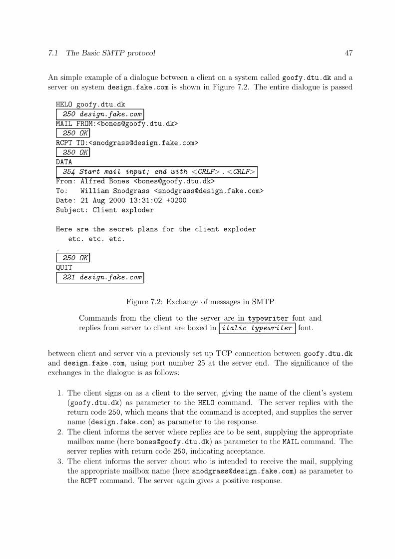
7.1 The Basic SMTP protocol 47
An simple example of a dialogue between a client on a system called goofy.dtu.dk and aserver on system design.fake.com is shown in Figure 7.2. The entire dialogue is passed
HELO goofy.dtu.dk
250 design.fake.com
MAIL FROM:<[email protected]>
250 OK
RCPT TO:<[email protected]>
250 OK
DATA
354 Start mail input; end with <CRLF> . <CRLF>
From: Alfred Bones <[email protected]>
To: William Snodgrass <[email protected]>
Date: 21 Aug 2000 13:31:02 +0200
Subject: Client exploder
Here are the secret plans for the client exploder
etc. etc. etc.
.
250 OK
QUIT
221 design.fake.com
Figure 7.2: Exchange of messages in SMTP
Commands from the client to the server are in typewriter font andreplies from server to client are boxed in italic typewriter font.
between client and server via a previously set up TCP connection between goofy.dtu.dk
and design.fake.com, using port number 25 at the server end. The significance of theexchanges in the dialogue is as follows:
1. The client signs on as a client to the server, giving the name of the client’s system(goofy.dtu.dk) as parameter to the HELO command. The server replies with thereturn code 250, which means that the command is accepted, and supplies the servername (design.fake.com) as parameter to the response.
2. The client informs the server where replies are to be sent, supplying the appropriatemailbox name (here [email protected]) as parameter to the MAIL command. Theserver replies with return code 250, indicating acceptance.
3. The client informs the server about who is intended to receive the mail, supplyingthe appropriate mailbox name (here [email protected]) as parameter tothe RCPT command. The server again gives a positive response.
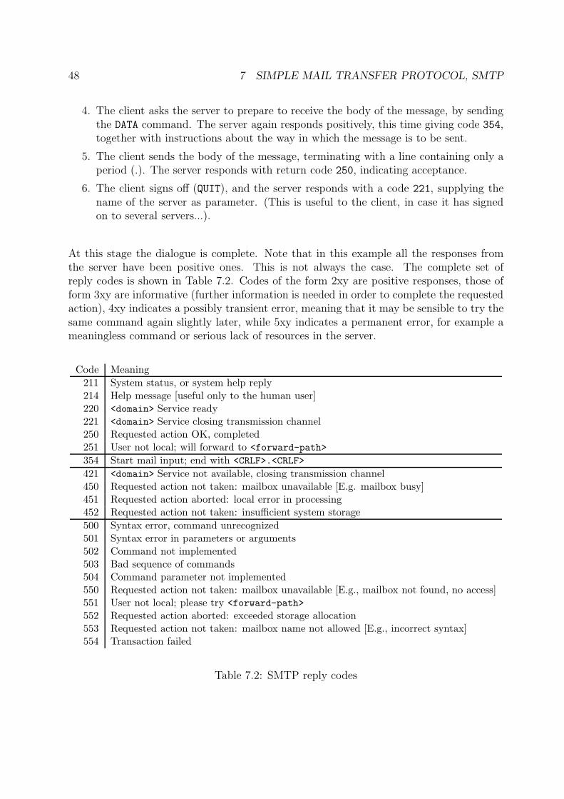
48 7 SIMPLE MAIL TRANSFER PROTOCOL, SMTP
4. The client asks the server to prepare to receive the body of the message, by sendingthe DATA command. The server again responds positively, this time giving code 354,together with instructions about the way in which the message is to be sent.
5. The client sends the body of the message, terminating with a line containing only aperiod (.). The server responds with return code 250, indicating acceptance.
6. The client signs off (QUIT), and the server responds with a code 221, supplying thename of the server as parameter. (This is useful to the client, in case it has signedon to several servers...).
At this stage the dialogue is complete. Note that in this example all the responses fromthe server have been positive ones. This is not always the case. The complete set ofreply codes is shown in Table 7.2. Codes of the form 2xy are positive responses, those ofform 3xy are informative (further information is needed in order to complete the requestedaction), 4xy indicates a possibly transient error, meaning that it may be sensible to try thesame command again slightly later, while 5xy indicates a permanent error, for example ameaningless command or serious lack of resources in the server.
Code Meaning
211 System status, or system help reply214 Help message [useful only to the human user]220 <domain> Service ready221 <domain> Service closing transmission channel250 Requested action OK, completed251 User not local; will forward to <forward-path>
354 Start mail input; end with <CRLF>.<CRLF>
421 <domain> Service not available, closing transmission channel450 Requested action not taken: mailbox unavailable [E.g. mailbox busy]451 Requested action aborted: local error in processing452 Requested action not taken: insufficient system storage
500 Syntax error, command unrecognized501 Syntax error in parameters or arguments502 Command not implemented503 Bad sequence of commands504 Command parameter not implemented550 Requested action not taken: mailbox unavailable [E.g., mailbox not found, no access]551 User not local; please try <forward-path>
552 Requested action aborted: exceeded storage allocation553 Requested action not taken: mailbox name not allowed [E.g., incorrect syntax]554 Transaction failed
Table 7.2: SMTP reply codes
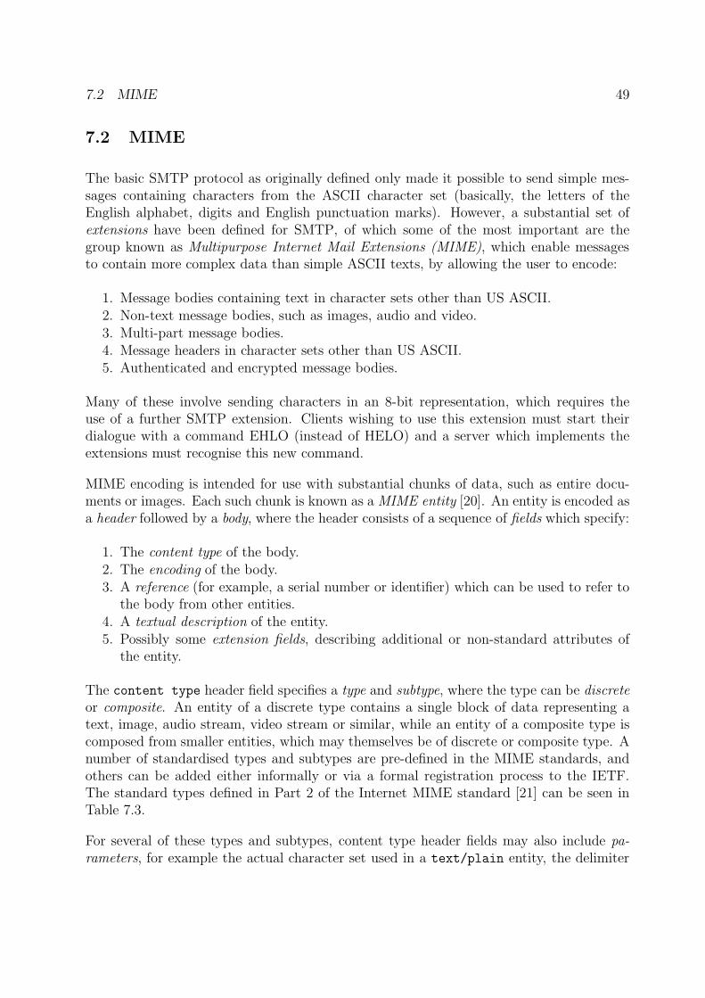
7.2 MIME 49
7.2 MIME
The basic SMTP protocol as originally defined only made it possible to send simple mes-sages containing characters from the ASCII character set (basically, the letters of theEnglish alphabet, digits and English punctuation marks). However, a substantial set ofextensions have been defined for SMTP, of which some of the most important are thegroup known as Multipurpose Internet Mail Extensions (MIME), which enable messagesto contain more complex data than simple ASCII texts, by allowing the user to encode:
1. Message bodies containing text in character sets other than US ASCII.2. Non-text message bodies, such as images, audio and video.3. Multi-part message bodies.4. Message headers in character sets other than US ASCII.5. Authenticated and encrypted message bodies.
Many of these involve sending characters in an 8-bit representation, which requires theuse of a further SMTP extension. Clients wishing to use this extension must start theirdialogue with a command EHLO (instead of HELO) and a server which implements theextensions must recognise this new command.
MIME encoding is intended for use with substantial chunks of data, such as entire docu-ments or images. Each such chunk is known as a MIME entity [20]. An entity is encoded asa header followed by a body, where the header consists of a sequence of fields which specify:
1. The content type of the body.2. The encoding of the body.3. A reference (for example, a serial number or identifier) which can be used to refer to
the body from other entities.4. A textual description of the entity.5. Possibly some extension fields, describing additional or non-standard attributes of
the entity.
The content type header field specifies a type and subtype, where the type can be discreteor composite. An entity of a discrete type contains a single block of data representing atext, image, audio stream, video stream or similar, while an entity of a composite type iscomposed from smaller entities, which may themselves be of discrete or composite type. Anumber of standardised types and subtypes are pre-defined in the MIME standards, andothers can be added either informally or via a formal registration process to the IETF.The standard types defined in Part 2 of the Internet MIME standard [21] can be seen inTable 7.3.
For several of these types and subtypes, content type header fields may also include pa-rameters, for example the actual character set used in a text/plain entity, the delimiter
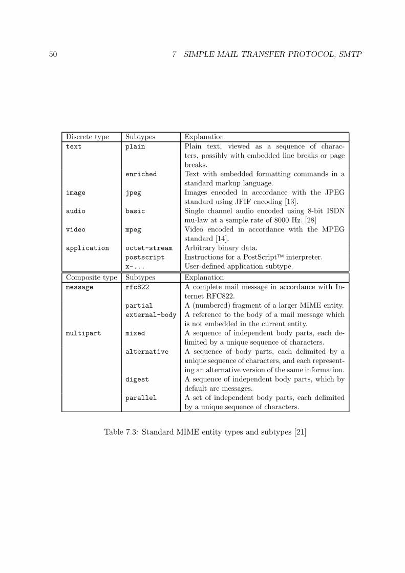
50 7 SIMPLE MAIL TRANSFER PROTOCOL, SMTP
Discrete type Subtypes Explanation
text plain Plain text, viewed as a sequence of charac-ters, possibly with embedded line breaks or pagebreaks.
enriched Text with embedded formatting commands in astandard markup language.
image jpeg Images encoded in accordance with the JPEGstandard using JFIF encoding [13].
audio basic Single channel audio encoded using 8-bit ISDNmu-law at a sample rate of 8000 Hz. [28]
video mpeg Video encoded in accordance with the MPEGstandard [14].
application octet-stream Arbitrary binary data.postscript Instructions for a PostScriptTM interpreter.x-... User-defined application subtype.
Composite type Subtypes Explanation
message rfc822 A complete mail message in accordance with In-ternet RFC822.
partial A (numbered) fragment of a larger MIME entity.external-body A reference to the body of a mail message which
is not embedded in the current entity.multipart mixed A sequence of independent body parts, each de-
limited by a unique sequence of characters.alternative A sequence of body parts, each delimited by a
unique sequence of characters, and each represent-ing an alternative version of the same information.
digest A sequence of independent body parts, which bydefault are messages.
parallel A set of independent body parts, each delimitedby a unique sequence of characters.
Table 7.3: Standard MIME entity types and subtypes [21]
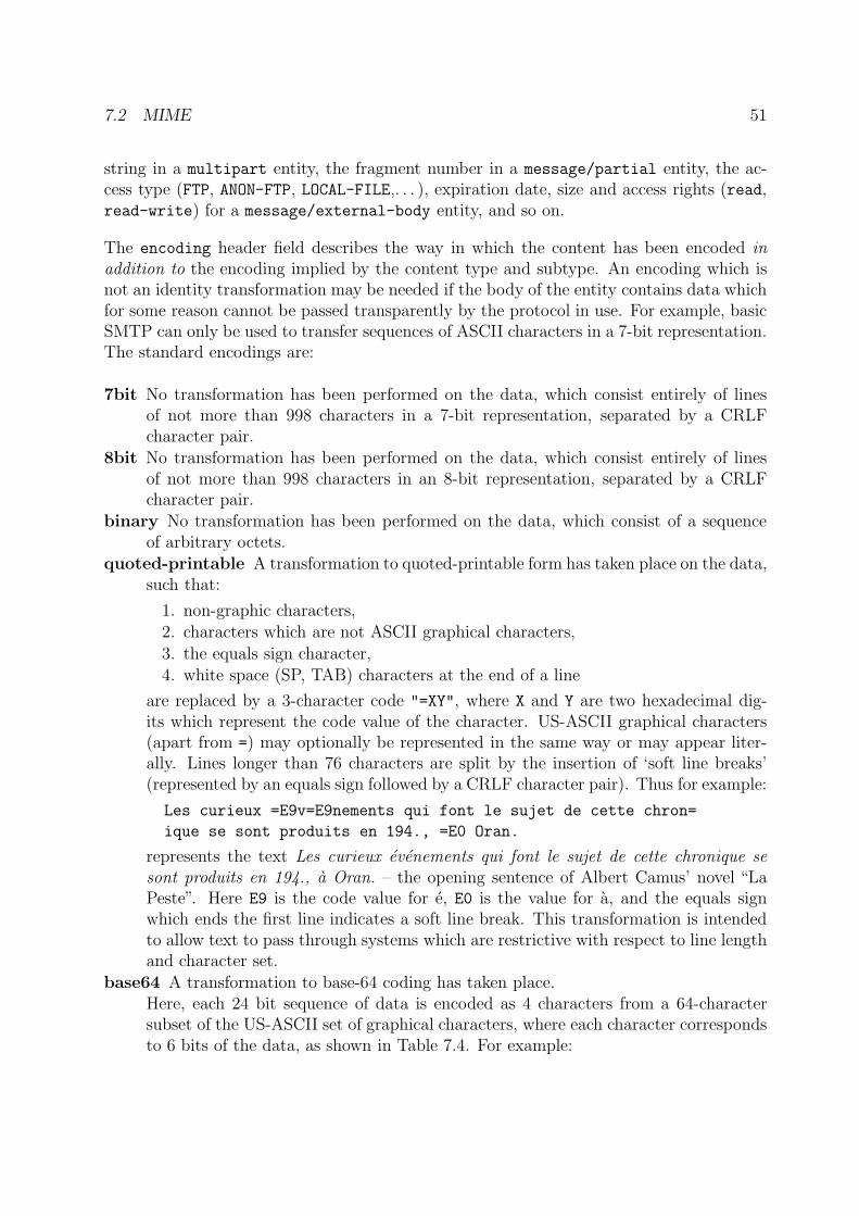
7.2 MIME 51
string in a multipart entity, the fragment number in a message/partial entity, the ac-cess type (FTP, ANON-FTP, LOCAL-FILE,. . . ), expiration date, size and access rights (read,read-write) for a message/external-body entity, and so on.
The encoding header field describes the way in which the content has been encoded inaddition to the encoding implied by the content type and subtype. An encoding which isnot an identity transformation may be needed if the body of the entity contains data whichfor some reason cannot be passed transparently by the protocol in use. For example, basicSMTP can only be used to transfer sequences of ASCII characters in a 7-bit representation.The standard encodings are:
7bit No transformation has been performed on the data, which consist entirely of linesof not more than 998 characters in a 7-bit representation, separated by a CRLFcharacter pair.
8bit No transformation has been performed on the data, which consist entirely of linesof not more than 998 characters in an 8-bit representation, separated by a CRLFcharacter pair.
binary No transformation has been performed on the data, which consist of a sequenceof arbitrary octets.
quoted-printable A transformation to quoted-printable form has taken place on the data,such that:
1. non-graphic characters,2. characters which are not ASCII graphical characters,
3. the equals sign character,4. white space (SP, TAB) characters at the end of a line
are replaced by a 3-character code "=XY", where X and Y are two hexadecimal dig-its which represent the code value of the character. US-ASCII graphical characters(apart from =) may optionally be represented in the same way or may appear liter-ally. Lines longer than 76 characters are split by the insertion of ‘soft line breaks’(represented by an equals sign followed by a CRLF character pair). Thus for example:
Les curieux =E9v=E9nements qui font le sujet de cette chron=
ique se sont produits en 194., =E0 Oran.
represents the text Les curieux evenements qui font le sujet de cette chronique sesont produits en 194., a Oran. – the opening sentence of Albert Camus’ novel “LaPeste”. Here E9 is the code value for e, E0 is the value for a, and the equals signwhich ends the first line indicates a soft line break. This transformation is intendedto allow text to pass through systems which are restrictive with respect to line lengthand character set.
base64 A transformation to base-64 coding has taken place.Here, each 24 bit sequence of data is encoded as 4 characters from a 64-charactersubset of the US-ASCII set of graphical characters, where each character correspondsto 6 bits of the data, as shown in Table 7.4. For example:
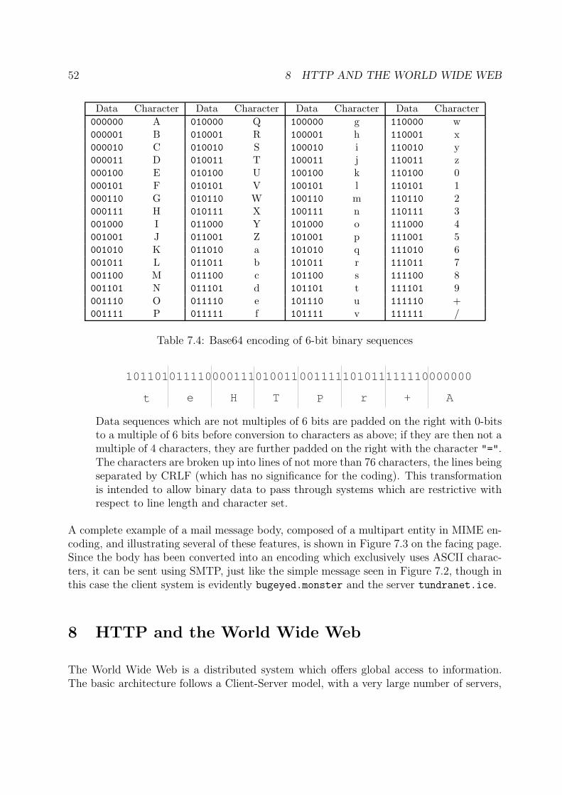
52 8 HTTP AND THE WORLD WIDE WEB
Data Character Data Character Data Character Data Character
000000 A 010000 Q 100000 g 110000 w000001 B 010001 R 100001 h 110001 x000010 C 010010 S 100010 i 110010 y000011 D 010011 T 100011 j 110011 z000100 E 010100 U 100100 k 110100 0000101 F 010101 V 100101 l 110101 1000110 G 010110 W 100110 m 110110 2000111 H 010111 X 100111 n 110111 3001000 I 011000 Y 101000 o 111000 4001001 J 011001 Z 101001 p 111001 5001010 K 011010 a 101010 q 111010 6001011 L 011011 b 101011 r 111011 7001100 M 011100 c 101100 s 111100 8001101 N 011101 d 101101 t 111101 9001110 O 011110 e 101110 u 111110 +001111 P 011111 f 101111 v 111111 /
Table 7.4: Base64 encoding of 6-bit binary sequences
101101011110000111010011
t e H T
001111101011111110000000
P r + A
Data sequences which are not multiples of 6 bits are padded on the right with 0-bitsto a multiple of 6 bits before conversion to characters as above; if they are then not amultiple of 4 characters, they are further padded on the right with the character "=".The characters are broken up into lines of not more than 76 characters, the lines beingseparated by CRLF (which has no significance for the coding). This transformationis intended to allow binary data to pass through systems which are restrictive withrespect to line length and character set.
A complete example of a mail message body, composed of a multipart entity in MIME en-coding, and illustrating several of these features, is shown in Figure 7.3 on the facing page.Since the body has been converted into an encoding which exclusively uses ASCII charac-ters, it can be sent using SMTP, just like the simple message seen in Figure 7.2, though inthis case the client system is evidently bugeyed.monster and the server tundranet.ice.
8 HTTP and the World Wide Web
The World Wide Web is a distributed system which offers global access to information.The basic architecture follows a Client-Server model, with a very large number of servers,
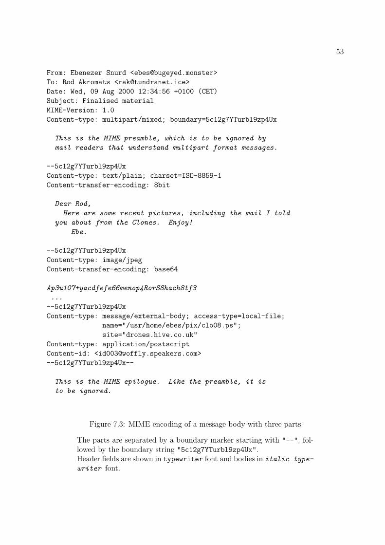
53
From: Ebenezer Snurd <[email protected]>
To: Rod Akromats <[email protected]>
Date: Wed, 09 Aug 2000 12:34:56 +0100 (CET)
Subject: Finalised material
MIME-Version: 1.0
Content-type: multipart/mixed; boundary=5c12g7YTurbl9zp4Ux
This is the MIME preamble, which is to be ignored by
mail readers that understand multipart format messages.
--5c12g7YTurbl9zp4Ux
Content-type: text/plain; charset=ISO-8859-1
Content-transfer-encoding: 8bit
Dear Rod,
Here are some recent pictures, including the mail I told
you about from the Clones. Enjoy!
Ebe.
--5c12g7YTurbl9zp4Ux
Content-type: image/jpeg
Content-transfer-encoding: base64
Ap3u107+yacdfefe66menop4RorS8hach8tf3
...
--5c12g7YTurbl9zp4Ux
Content-type: message/external-body; access-type=local-file;
name="/usr/home/ebes/pix/clo08.ps";
site="drones.hive.co.uk"
Content-type: application/postscript
Content-id: <[email protected]>
--5c12g7YTurbl9zp4Ux--
This is the MIME epilogue. Like the preamble, it is
to be ignored.
Figure 7.3: MIME encoding of a message body with three parts
The parts are separated by a boundary marker starting with "--", fol-lowed by the boundary string "5c12g7YTurbl9zp4Ux".Header fields are shown in typewriter font and bodies in italic type-
writer font.
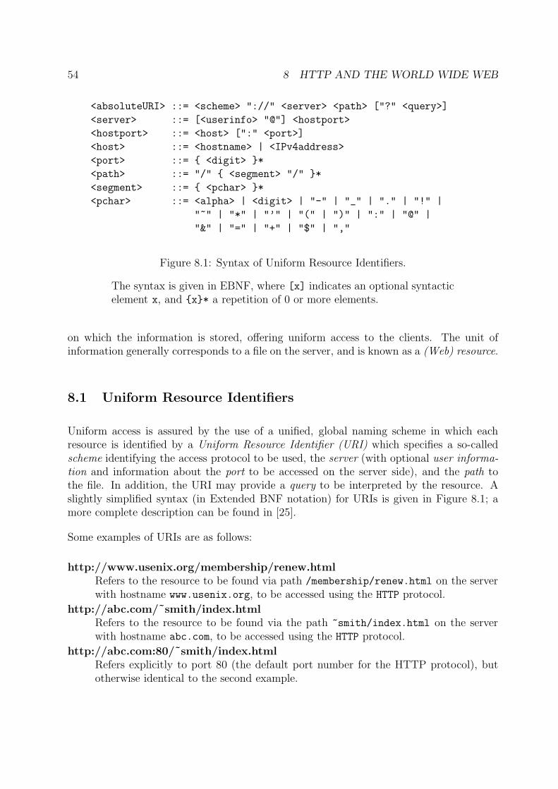
54 8 HTTP AND THE WORLD WIDE WEB
<absoluteURI> ::= <scheme> "://" <server> <path> ["?" <query>]
<server> ::= [<userinfo> "@"] <hostport>
<hostport> ::= <host> [":" <port>]
<host> ::= <hostname> | <IPv4address>
<port> ::= { <digit> }*
<path> ::= "/" { <segment> "/" }*
<segment> ::= { <pchar> }*
<pchar> ::= <alpha> | <digit> | "-" | "_" | "." | "!" |
"~" | "*" | "’" | "(" | ")" | ":" | "@" |
"&" | "=" | "+" | "$" | ","
Figure 8.1: Syntax of Uniform Resource Identifiers.
The syntax is given in EBNF, where [x] indicates an optional syntacticelement x, and {x}* a repetition of 0 or more elements.
on which the information is stored, offering uniform access to the clients. The unit ofinformation generally corresponds to a file on the server, and is known as a (Web) resource.
8.1 Uniform Resource Identifiers
Uniform access is assured by the use of a unified, global naming scheme in which eachresource is identified by a Uniform Resource Identifier (URI) which specifies a so-calledscheme identifying the access protocol to be used, the server (with optional user informa-tion and information about the port to be accessed on the server side), and the path tothe file. In addition, the URI may provide a query to be interpreted by the resource. Aslightly simplified syntax (in Extended BNF notation) for URIs is given in Figure 8.1; amore complete description can be found in [25].
Some examples of URIs are as follows:
http://www.usenix.org/membership/renew.htmlRefers to the resource to be found via path /membership/renew.html on the serverwith hostname www.usenix.org, to be accessed using the HTTP protocol.
http://abc.com/˜smith/index.htmlRefers to the resource to be found via the path ~smith/index.html on the serverwith hostname abc.com, to be accessed using the HTTP protocol.
http://abc.com:80/˜smith/index.htmlRefers explicitly to port 80 (the default port number for the HTTP protocol), butotherwise identical to the second example.
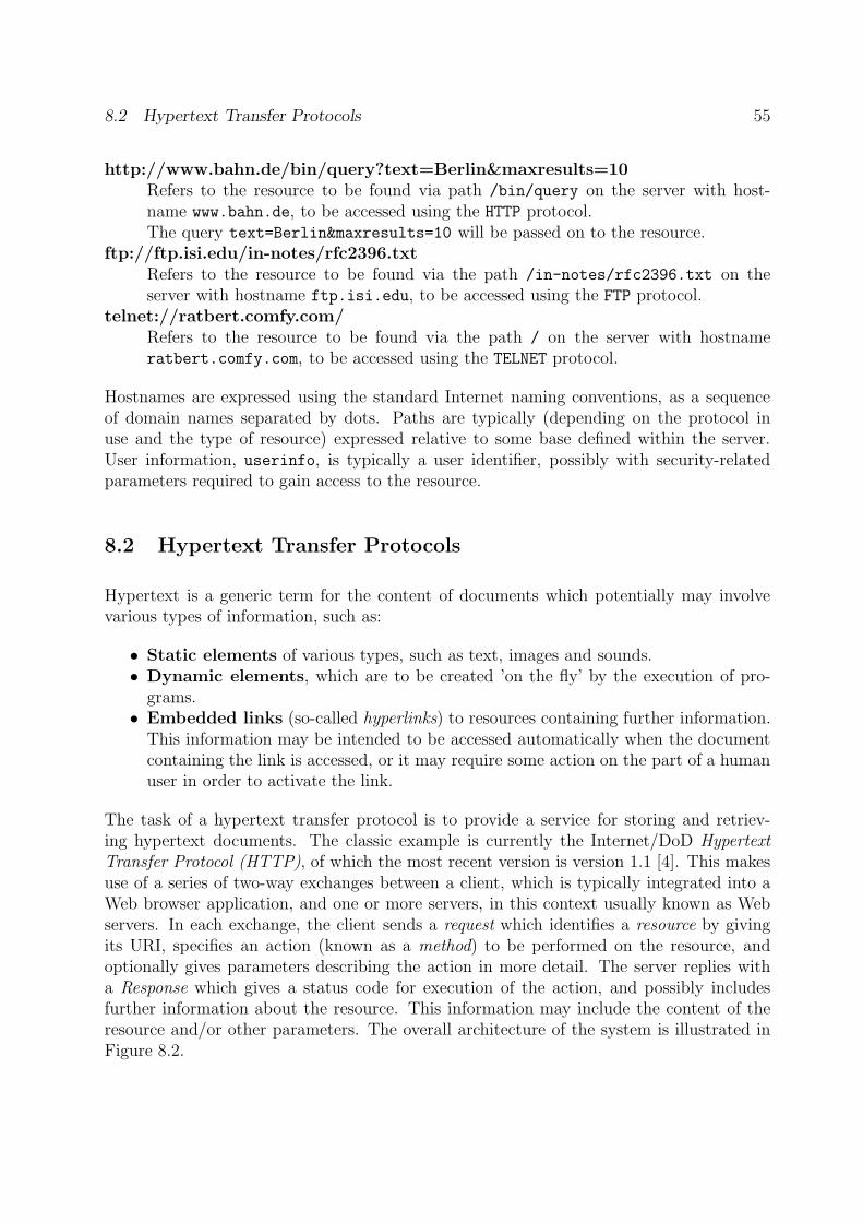
8.2 Hypertext Transfer Protocols 55
http://www.bahn.de/bin/query?text=Berlin&maxresults=10Refers to the resource to be found via path /bin/query on the server with host-name www.bahn.de, to be accessed using the HTTP protocol.The query text=Berlin&maxresults=10 will be passed on to the resource.
ftp://ftp.isi.edu/in-notes/rfc2396.txtRefers to the resource to be found via the path /in-notes/rfc2396.txt on theserver with hostname ftp.isi.edu, to be accessed using the FTP protocol.
telnet://ratbert.comfy.com/Refers to the resource to be found via the path / on the server with hostnameratbert.comfy.com, to be accessed using the TELNET protocol.
Hostnames are expressed using the standard Internet naming conventions, as a sequenceof domain names separated by dots. Paths are typically (depending on the protocol inuse and the type of resource) expressed relative to some base defined within the server.User information, userinfo, is typically a user identifier, possibly with security-relatedparameters required to gain access to the resource.
8.2 Hypertext Transfer Protocols
Hypertext is a generic term for the content of documents which potentially may involvevarious types of information, such as:
• Static elements of various types, such as text, images and sounds.• Dynamic elements, which are to be created ’on the fly’ by the execution of pro-
grams.• Embedded links (so-called hyperlinks) to resources containing further information.
This information may be intended to be accessed automatically when the documentcontaining the link is accessed, or it may require some action on the part of a humanuser in order to activate the link.
The task of a hypertext transfer protocol is to provide a service for storing and retriev-ing hypertext documents. The classic example is currently the Internet/DoD HypertextTransfer Protocol (HTTP), of which the most recent version is version 1.1 [4]. This makesuse of a series of two-way exchanges between a client, which is typically integrated into aWeb browser application, and one or more servers, in this context usually known as Webservers. In each exchange, the client sends a request which identifies a resource by givingits URI, specifies an action (known as a method) to be performed on the resource, andoptionally gives parameters describing the action in more detail. The server replies witha Response which gives a status code for execution of the action, and possibly includesfurther information about the resource. This information may include the content of theresource and/or other parameters. The overall architecture of the system is illustrated inFigure 8.2.
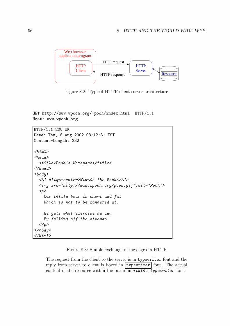
56 8 HTTP AND THE WORLD WIDE WEB
HTTPClient
HTTPServer
Web browserapplication program
HTTP request
HTTP response Resource
Figure 8.2: Typical HTTP client-server architecture
GET http://www.wpooh.org/~pooh/index.html HTTP/1.1
Host: www.wpooh.org
HTTP/1.1 200 OK
Date: Thu, 8 Aug 2002 08:12:31 EST
Content-Length: 332
<html>
<head>
<title>Pooh’s Homepage</title>
</head>
<body>
<h1 align=center>Winnie the Pooh</h1>
<img src="http://www.wpooh.org/pooh.gif",alt="Pooh">
<p>
Our little bear is short and fat
Which is not to be wondered at.
He gets what exercise he can
By falling off the ottoman.
</p>
</body>
</html>
Figure 8.3: Simple exchange of messages in HTTP
The request from the client to the server is in typewriter font and thereply from server to client is boxed in typewriter font. The actualcontent of the resource within the box is in italic typewriter font.
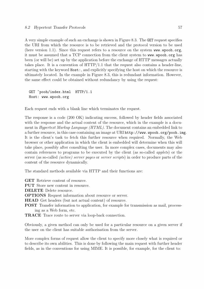
8.2 Hypertext Transfer Protocols 57
A very simple example of such an exchange is shown in Figure 8.3. The GET request specifiesthe URI from which the resource is to be retrieved and the protocol version to be used(here version 1.1). Since this request refers to a resource on the system www.wpooh.org,it must be assumed that a TCP connection from the client system to www.wpooh.org hasbeen (or will be) set up by the application before the exchange of HTTP messages actuallytakes place. It is a convention of HTTP/1.1 that the request also contains a header-line,starting with the keyword Host:, and explicitly specifying the host on which the resource isultimately located. In the example in Figure 8.3, this is redundant information. However,the same effect could be obtained without redundancy by using the request:
GET ~pooh/index.html HTTP/1.1
Host: www.wpooh.org
Each request ends with a blank line which terminates the request.
The response is a code (200 OK) indicating success, followed by header fields associatedwith the response and the actual content of the resource, which in the example is a docu-ment in Hypertext Markup Language (HTML). The document contains an embedded link toa further resource, in this case containing an image at URI http://www.wpooh.org/pooh.img.It is the client’s task to fetch this further resource when required. Normally, the Webbrowser or other application in which the client is embedded will determine when this willtake place, possibly after consulting the user. In more complex cases, documents may alsocontain references to programs to be executed by the client (as so-called applets) or theserver (as so-called (active) server pages or server scripts) in order to produce parts of thecontent of the resource dynamically.
The standard methods available via HTTP and their functions are:
GET Retrieve content of resource.PUT Store new content in resource.DELETE Delete resource.OPTIONS Request information about resource or server.HEAD Get headers (but not actual content) of resource.POST Transfer information to application, for example for transmission as mail, process-
ing as a Web form, etc.TRACE Trace route to server via loop-back connection.
Obviously, a given method can only be used for a particular resource on a given server ifthe user on the client has suitable authorisation from the server.
More complex forms of request allow the client to specify more closely what is required orto describe its own abilities. This is done by following the main request with further headerfields, as in the conventions for using MIME. It is possible, for example, for the client to:
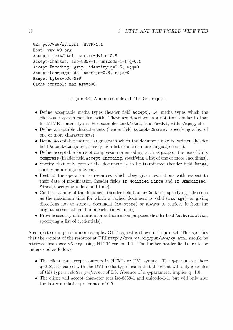
58 8 HTTP AND THE WORLD WIDE WEB
GET pub/WWW/xy.html HTTP/1.1
Host: www.w3.org
Accept: text/html, text/x-dvi;q=0.8
Accept-Charset: iso-8859-1, unicode-1-1;q=0.5
Accept-Encoding: gzip, identity;q=0.5, *;q=0
Accept-Language: da, en-gb;q=0.8, en;q=0
Range: bytes=500-999
Cache-control: max-age=600
Figure 8.4: A more complex HTTP Get request
• Define acceptable media types (header field Accept), i.e. media types which theclient-side system can deal with. These are described in a notation similar to thatfor MIME content-types. For example: text/html, text/x-dvi, video/mpeg, etc.
• Define acceptable character sets (header field Accept-Charset, specifying a list ofone or more character sets).
• Define acceptable natural languages in which the document may be written (headerfield Accept-Language, specifying a list or one or more language codes).
• Define acceptable forms of compression or encoding, such as gzip or the use of Unixcompress (header field Accept-Encoding, specifying a list of one or more encodings).
• Specify that only part of the document is to be transferred (header field Range,specifying a range in bytes).
• Restrict the operation to resources which obey given restrictions with respect totheir date of modification (header fields If-Modified-Since and If-Unmodified-
Since, specifying a date and time).• Control caching of the document (header field Cache-Control, specifying rules such
as the maximum time for which a cached document is valid (max-age), or givingdirections not to store a document (no-store) or always to retrieve it from theoriginal server rather than a cache (no-cache)).
• Provide security information for authorisation purposes (header field Authorization,specifying a list of credentials).
A complete example of a more complex GET request is shown in Figure 8.4. This specifiesthat the content of the resource at URI http://www.w3.org/pub/WWW/xy.html should beretrieved from www.w3.org using HTTP version 1.1. The further header fields are to beunderstood as follows:
• The client can accept contents in HTML or DVI syntax. The q-parameter, hereq=0.8, associated with the DVI media type means that the client will only give filesof this type a relative preference of 0.8. Absence of a q-parameter implies q=1.0.
• The client will accept character sets iso-8859-1 and unicode-1-1, but will only givethe latter a relative preference of 0.5.
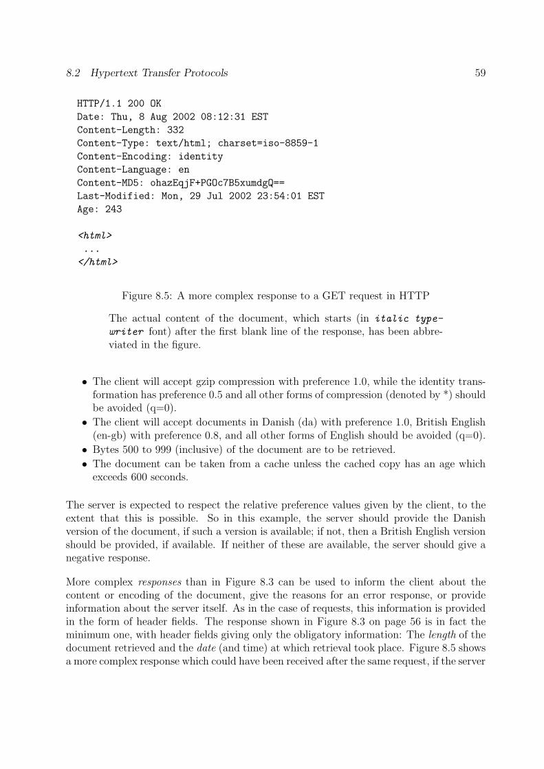
8.2 Hypertext Transfer Protocols 59
HTTP/1.1 200 OK
Date: Thu, 8 Aug 2002 08:12:31 EST
Content-Length: 332
Content-Type: text/html; charset=iso-8859-1
Content-Encoding: identity
Content-Language: en
Content-MD5: ohazEqjF+PGOc7B5xumdgQ==
Last-Modified: Mon, 29 Jul 2002 23:54:01 EST
Age: 243
<html>
...
</html>
Figure 8.5: A more complex response to a GET request in HTTP
The actual content of the document, which starts (in italic type-
writer font) after the first blank line of the response, has been abbre-viated in the figure.
• The client will accept gzip compression with preference 1.0, while the identity trans-formation has preference 0.5 and all other forms of compression (denoted by *) shouldbe avoided (q=0).
• The client will accept documents in Danish (da) with preference 1.0, British English(en-gb) with preference 0.8, and all other forms of English should be avoided (q=0).
• Bytes 500 to 999 (inclusive) of the document are to be retrieved.
• The document can be taken from a cache unless the cached copy has an age whichexceeds 600 seconds.
The server is expected to respect the relative preference values given by the client, to theextent that this is possible. So in this example, the server should provide the Danishversion of the document, if such a version is available; if not, then a British English versionshould be provided, if available. If neither of these are available, the server should give anegative response.
More complex responses than in Figure 8.3 can be used to inform the client about thecontent or encoding of the document, give the reasons for an error response, or provideinformation about the server itself. As in the case of requests, this information is providedin the form of header fields. The response shown in Figure 8.3 on page 56 is in fact theminimum one, with header fields giving only the obligatory information: The length of thedocument retrieved and the date (and time) at which retrieval took place. Figure 8.5 showsa more complex response which could have been received after the same request, if the server
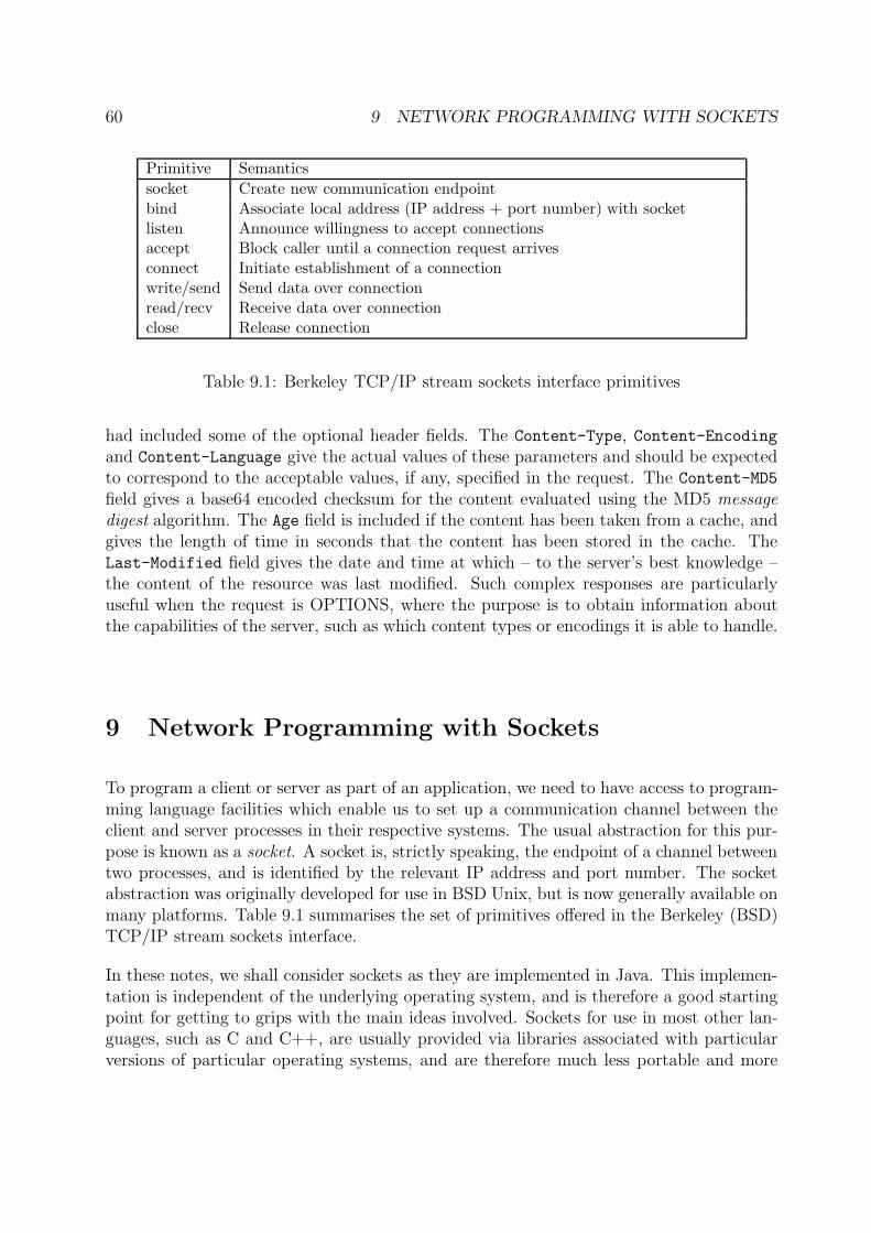
60 9 NETWORK PROGRAMMING WITH SOCKETS
Primitive Semantics
socket Create new communication endpointbind Associate local address (IP address + port number) with socketlisten Announce willingness to accept connectionsaccept Block caller until a connection request arrivesconnect Initiate establishment of a connectionwrite/send Send data over connectionread/recv Receive data over connectionclose Release connection
Table 9.1: Berkeley TCP/IP stream sockets interface primitives
had included some of the optional header fields. The Content-Type, Content-Encodingand Content-Language give the actual values of these parameters and should be expectedto correspond to the acceptable values, if any, specified in the request. The Content-MD5
field gives a base64 encoded checksum for the content evaluated using the MD5 messagedigest algorithm. The Age field is included if the content has been taken from a cache, andgives the length of time in seconds that the content has been stored in the cache. TheLast-Modified field gives the date and time at which – to the server’s best knowledge –the content of the resource was last modified. Such complex responses are particularlyuseful when the request is OPTIONS, where the purpose is to obtain information aboutthe capabilities of the server, such as which content types or encodings it is able to handle.
9 Network Programming with Sockets
To program a client or server as part of an application, we need to have access to program-ming language facilities which enable us to set up a communication channel between theclient and server processes in their respective systems. The usual abstraction for this pur-pose is known as a socket. A socket is, strictly speaking, the endpoint of a channel betweentwo processes, and is identified by the relevant IP address and port number. The socketabstraction was originally developed for use in BSD Unix, but is now generally available onmany platforms. Table 9.1 summarises the set of primitives offered in the Berkeley (BSD)TCP/IP stream sockets interface.
In these notes, we shall consider sockets as they are implemented in Java. This implemen-tation is independent of the underlying operating system, and is therefore a good startingpoint for getting to grips with the main ideas involved. Sockets for use in most other lan-guages, such as C and C++, are usually provided via libraries associated with particularversions of particular operating systems, and are therefore much less portable and more
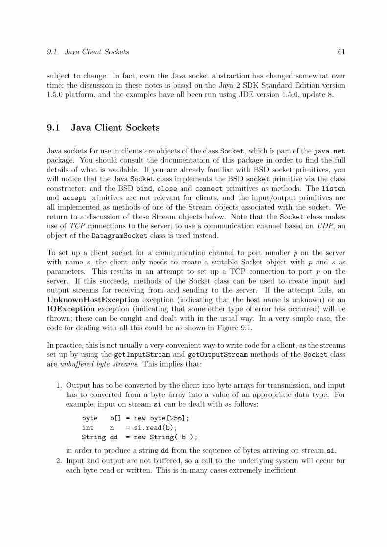
9.1 Java Client Sockets 61
subject to change. In fact, even the Java socket abstraction has changed somewhat overtime; the discussion in these notes is based on the Java 2 SDK Standard Edition version1.5.0 platform, and the examples have all been run using JDE version 1.5.0, update 8.
9.1 Java Client Sockets
Java sockets for use in clients are objects of the class Socket, which is part of the java.netpackage. You should consult the documentation of this package in order to find the fulldetails of what is available. If you are already familiar with BSD socket primitives, youwill notice that the Java Socket class implements the BSD socket primitive via the classconstructor, and the BSD bind, close and connect primitives as methods. The listen
and accept primitives are not relevant for clients, and the input/output primitives areall implemented as methods of one of the Stream objects associated with the socket. Wereturn to a discussion of these Stream objects below. Note that the Socket class makesuse of TCP connections to the server; to use a communication channel based on UDP, anobject of the DatagramSocket class is used instead.
To set up a client socket for a communication channel to port number p on the serverwith name s, the client only needs to create a suitable Socket object with p and s asparameters. This results in an attempt to set up a TCP connection to port p on theserver. If this succeeds, methods of the Socket class can be used to create input andoutput streams for receiving from and sending to the server. If the attempt fails, anUnknownHostException exception (indicating that the host name is unknown) or anIOException exception (indicating that some other type of error has occurred) will bethrown; these can be caught and dealt with in the usual way. In a very simple case, thecode for dealing with all this could be as shown in Figure 9.1.
In practice, this is not usually a very convenient way to write code for a client, as the streamsset up by using the getInputStream and getOutputStream methods of the Socket classare unbuffered byte streams. This implies that:
1. Output has to be converted by the client into byte arrays for transmission, and inputhas to converted from a byte array into a value of an appropriate data type. Forexample, input on stream si can be dealt with as follows:
byte b[] = new byte[256];
int n = si.read(b);
String dd = new String( b );
in order to produce a string dd from the sequence of bytes arriving on stream si.
2. Input and output are not buffered, so a call to the underlying system will occur foreach byte read or written. This is in many cases extremely inefficient.
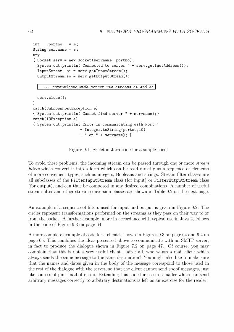
62 9 NETWORK PROGRAMMING WITH SOCKETS
int portno = p ;
String servname = s ;
try
{ Socket serv = new Socket(servname, portno);
System.out.println("Connected to server " + serv.getInetAddress());
InputStream si = serv.getInputStream();
OutputStream so = serv.getOutputStream();
... communicate with server via streams si and so
serv.close();
}
catch(UnknownHostException e)
{ System.out.println("Cannot find server " + servname);}
catch(IOException e)
{ System.out.println("Error in communicating with Port "
+ Integer.toString(portno,10)
+ " on " + servname); }
Figure 9.1: Skeleton Java code for a simple client
To avoid these problems, the incoming stream can be passed through one or more streamfilters which convert it into a form which can be read directly as a sequence of elementsof more convenient types, such as integers, Booleans and strings. Stream filter classes areall subclasses of the FilterInputStream class (for input) or FilterOutputStream class(for output), and can thus be composed in any desired combinations. A number of usefulstream filter and other stream conversion classes are shown in Table 9.2 on the next page.
An example of a sequence of filters used for input and output is given in Figure 9.2. Thecircles represent transformations performed on the streams as they pass on their way to orfrom the socket. A further example, more in accordance with typical use in Java 2, followsin the code of Figure 9.3 on page 64
A more complete example of code for a client is shown in Figures 9.3 on page 64 and 9.4 onpage 65. This combines the ideas presented above to communicate with an SMTP server,in fact to produce the dialogue shown in Figure 7.2 on page 47. Of course, you maycomplain that this is not a very useful client – after all, who wants a mail client whichalways sends the same message to the same destination? You might also like to make surethat the names and dates given in the body of the message correspond to those used inthe rest of the dialogue with the server, so that the client cannot send spoof messages, justlike sources of junk mail often do. Extending this code for use in a mailer which can sendarbitrary messages correctly to arbitrary destinations is left as an exercise for the reader.
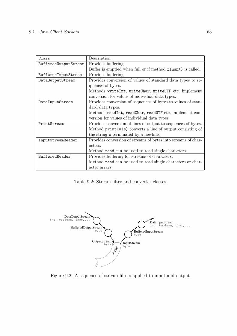
9.1 Java Client Sockets 63
Class Description
BufferedOutputStream Provides buffering.Buffer is emptied when full or if method flush() is called.
BufferedInputStream Provides buffering.
DataOutputStream Provides conversion of values of standard data types to se-quences of bytes.Methods writeInt, writeChar, writeUTF etc. implementconversion for values of individual data types.
DataInputStream Provides conversion of sequences of bytes to values of stan-dard data types.Methods readInt, readChar, readUTF etc. implement con-version for values of individual data types.
PrintStream Provides conversion of lines of output to sequences of bytes.Method println(s) converts a line of output consisting ofthe string s terminated by a newline.
InputStreamReader Provides conversion of streams of bytes into streams of char-acters.Method read can be used to read single characters.
BufferedReader Provides buffering for streams of characters.Method read can be used to read single characters or char-acter arrays.
Table 9.2: Stream filter and converter classes
Sock
et
InputStream
BufferedInputStream
DataInputStream
OutputStream
BufferedOutputStream
DataOutputStream
int, boolean, char,...
int, boolean, char,...
bytebyte
bytebyte
Figure 9.2: A sequence of stream filters applied to input and output
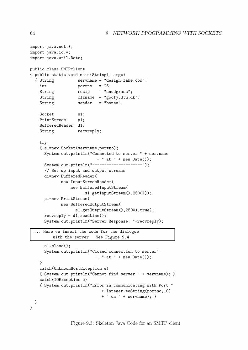
64 9 NETWORK PROGRAMMING WITH SOCKETS
import java.net.*;
import java.io.*;
import java.util.Date;
public class SMTPclient
{ public static void main(String[] argc)
{ String servname = "design.fake.com";
int portno = 25;
String recip = "snodgrass";
String cliname = "goofy.dtu.dk";
String sender = "bones";
Socket s1;
PrintStream p1;
BufferedReader d1;
String recvreply;
try
{ s1=new Socket(servname,portno);
System.out.println("Connected to server " + servname
+ " at " + new Date());
System.out.println("---------------------");
// Set up input and output streams
d1=new BufferedReader(
new InputStreamReader(
new BufferedInputStream(
s1.getInputStream(),2500)));
p1=new PrintStream(
new BufferedOutputStream(
s1.getOutputStream(),2500),true);
recvreply = d1.readLine();
System.out.println("Server Response: "+recvreply);
... Here we insert the code for the dialogue
with the server. See Figure 9.4
s1.close();
System.out.println("Closed connection to server"
+ " at " + new Date());
}
catch(UnknownHostException e)
{ System.out.println("Cannot find server " + servname); }
catch(IOException e)
{ System.out.println("Error in communicating with Port "
+ Integer.toString(portno,10)
+ " on " + servname); }
}
}
Figure 9.3: Skeleton Java Code for an SMTP client
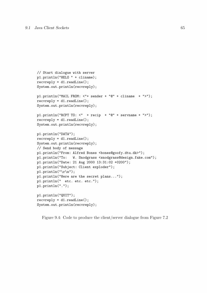
9.1 Java Client Sockets 65
// Start dialogue with server
p1.println("HELO " + cliname);
recvreply = d1.readLine();
System.out.println(recvreply);
p1.println("MAIL FROM: <"+ sender + "@" + cliname + ">");
recvreply = d1.readLine();
System.out.println(recvreply);
p1.println("RCPT TO: <" + recip + "@" + servname + ">");
recvreply = d1.readLine();
System.out.println(recvreply);
p1.println("DATA");
recvreply = d1.readLine();
System.out.println(recvreply);
// Send body of message
p1.println("From: Alfred Bones <[email protected]>");
p1.println("To: W. Snodgrass <[email protected]");
p1.println("Date: 21 Aug 2000 13:31:02 +0200");
p1.println("Subject: Client exploder");
p1.println("\r\n");
p1.println("Here are the secret plans...");
p1.println(" etc. etc. etc.");
p1.println(".");
p1.println("QUIT");
recvreply = d1.readLine();
System.out.println(recvreply);
Figure 9.4: Code to produce the client/server dialogue from Figure 7.2
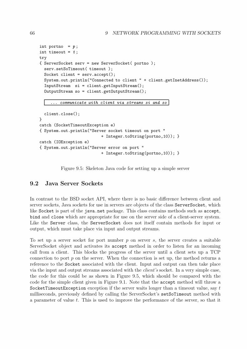
66 9 NETWORK PROGRAMMING WITH SOCKETS
int portno = p ;
int timeout = t ;
try
{ ServerSocket serv = new ServerSocket( portno );
serv.setSoTimeout( timeout );
Socket client = serv.accept();
System.out.println("Connected to client " + client.getInetAddress());
InputStream si = client.getInputStream();
OutputStream so = client.getOutputStream();
... communicate with client via streams si and so
client.close();
}
catch (SocketTimeoutException e)
{ System.out.println("Server socket timeout on port "
+ Integer.toString(portno,10)); }
catch (IOException e)
{ System.out.println("Server error on port "
+ Integer.toString(portno,10)); }
Figure 9.5: Skeleton Java code for setting up a simple server
9.2 Java Server Sockets
In contrast to the BSD socket API, where there is no basic difference between client andserver sockets, Java sockets for use in servers are objects of the class ServerSocket, whichlike Socket is part of the java.net package. This class contains methods such as accept,bind and close which are appropriate for use on the server side of a client-server system.Like the Server class, the ServerSocket does not itself contain methods for input oroutput, which must take place via input and output streams.
To set up a server socket for port number p on server s, the server creates a suitableServerSocket object and activates its accept method in order to listen for an incomingcall from a client. This blocks the progress of the server until a client sets up a TCPconnection to port p on the server. When the connection is set up, the method returns areference to the Socket associated with the client. Input and output can then take placevia the input and output streams associated with the client’s socket. In a very simple case,the code for this could be as shown in Figure 9.5, which should be compared with thecode for the simple client given in Figure 9.1. Note that the accept method will throw aSocketTimeoutException exception if the server waits longer than a timeout value, say t
milliseconds, previously defined by calling the ServerSocket’s setSoTimeout method witha parameter of value t. This is used to improve the performance of the server, so that it
67
does not just “hang” if no clients are active.
The example given here is very simple, and for practical use would need to be extended inseveral ways. Firstly, the code would usually be modified to use appropriate stream filterson the input and output streams, as in the case of the SMTP client shown in Figure 9.3.Secondly, we note that the server only has a single thread of control, so only one client canbe dealt with for each activation of the server. This is hardly appropriate for use in a realsystem. As a minimum, the code shown here would be placed in a loop, so that severalclients could be dealt with sequentially. More typically, the server would be organised tostart a new thread for dealing with each new client which calls up, and to kill the threadwhen the dialogue with the client terminates. Or, for increased efficiency, the server couldset up a pool of threads in a wait state, releasing one of them whan a new client calls upand returning the thread to the waiting pool when the client terminates. Extending thecode of Figure 9.5 to use threads is left as an exercise for the reader.
10 Remote Procedures and Objects
Simple network socket programming, where two parties interact by directly exchangingmessages over a logical channel between them, is the most basic paradigm for distributedprogramming. However, if we pursue the idea that a server’s purpose is to offer some kindof services to its clients, then we would often prefer to hide the details of the exchangeof messages, and offer the programmer a programming model which allows the client toperform some action on the remote server. In this section we shall look at two such models:
Remote Procedure Call (RPC), where the client is able to call a procedure which isexecuted on the server, possibly returning results to the client.
Remote Object Invocation (ROI), where the client is able to activate a method on aserver, which is regarded as an object.
10.1 Remote Procedure Call
An essential element in distributed systems based on the Client-Server paradigm is theRemote Procedure Call (RPC) abstraction. This offers an interface which appears to beidentical with an ordinary procedure call, but where the called procedure may be in anotherprocess in the same machine or on a remote system. RPC was originally defined by Birrelland Nelson [1] as “the synchronous language-level transfer of control between programs indisjoint address spaces, whose primary communication medium is a narrow channel”, adefinition which stresses three important properties of RPC:
1. The participants are in different address spaces.
68 10 REMOTE PROCEDURES AND OBJECTS
2. There is a (logical) channel which permits transfer of data between the participants.3. Transfer of data is associated with transfer of control, as in activation of ordinary
procedures in classical programming languages.
Subsequent work on RPC mechanisms has occasionally deviated from the definition onother points, for example by providing asynchronous (non-blocking) rather than syn-chronous (blocking) transfer of control, while the narrowness of the channel depends onthe technology used, and can obviously be debated.
The semantics of actually executing the procedure may in fact deviate from what wouldbe expected with a traditional procedure call, since after a failure in a remote machineit may be impossible to tell whether a message requesting execution of a procedure hasbeen received and acted upon. Repeating the message may cause the procedure to beexecuted more than once; on the other hand, failing to repeat the message may resultin the procedure not being executed at all. It has become conventional to refer to RPCmechanisms as having different call semantics, depending on what is guaranteed, as follows:
Exactly-once: The system guarantees that the procedure will return a result after beingexecuted once, just as in a traditional local procedure call.
At-most-once: The system guarantees that the procedure will return a result after beingexecuted not more than once.
At-least-once: The system guarantees that the procedure will return a result after beingexecuted one or more times.
Maybe: The system makes no guarantees about execution of the procedure or the returnof results after a failure.
Exactly-once semantics is unfortunately extremely costly, if not impossible, to achieve ina distributed system; this may make it difficult to ensure that local and remote RPC workin the same way. On the other hand, with at-most-once or maybe semantics there is a riskthat the procedure will not be executed at all, while a system with at-least-once semanticswill possibly execute the procedure several times. This can be tolerated if the procedure isidempotent, i.e. leads to the same result regardless of how many times execution is repeated,whereas it is a problem if the procedure has side effects.
The standard view of a system which uses RPC is shown in Figure 10.1. Both the callingprocess (the caller) and the called procedure (the callee) see an interface just as if it werea local procedure being activated. To make this possible when the caller and callee residein different address spaces, each is extended with a stub, which passes the parameters andresults to the underlying communication system for transfer between the processes. Thecaller and its associated stub make up the client and the callee and its stub make up theserver8.
8In some RPC-based systems, servers are known as objects, to underline the similarity between client-server systems and the caller/object structure characteristic of object oriented systems.
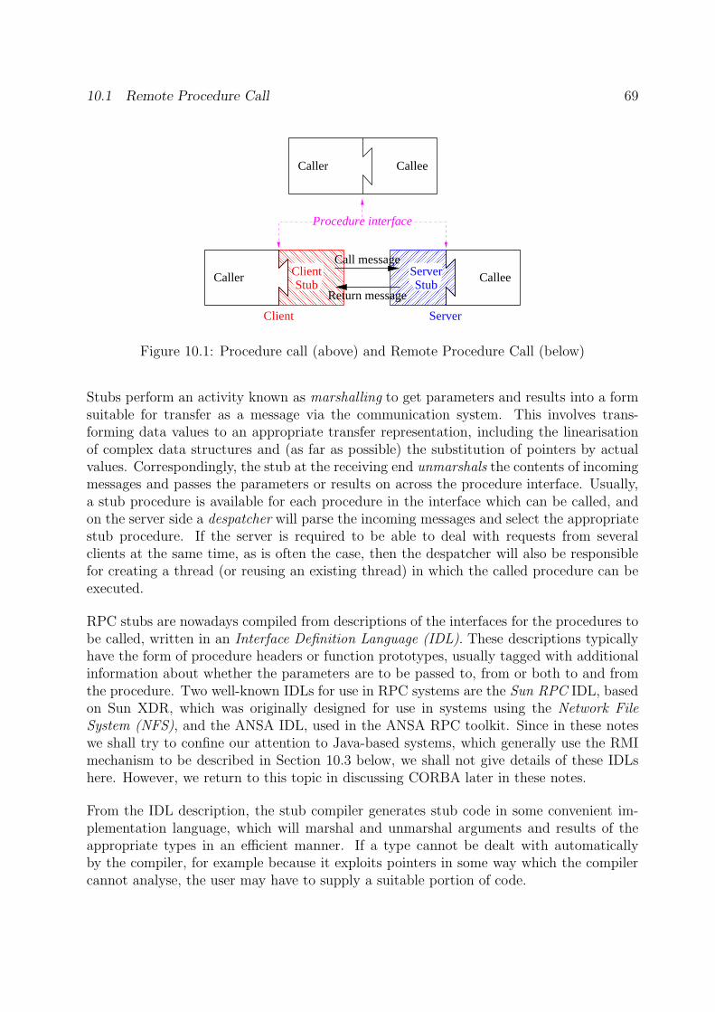
10.1 Remote Procedure Call 69
�������������������������������������������������
�������������������������������������������������
�������������������������������������������������
�������������������������������������������������
Caller Callee
Return message
Caller Callee
Call message
StubServerStub
Procedure interface
Client Server
Client
Figure 10.1: Procedure call (above) and Remote Procedure Call (below)
Stubs perform an activity known as marshalling to get parameters and results into a formsuitable for transfer as a message via the communication system. This involves trans-forming data values to an appropriate transfer representation, including the linearisationof complex data structures and (as far as possible) the substitution of pointers by actualvalues. Correspondingly, the stub at the receiving end unmarshals the contents of incomingmessages and passes the parameters or results on across the procedure interface. Usually,a stub procedure is available for each procedure in the interface which can be called, andon the server side a despatcher will parse the incoming messages and select the appropriatestub procedure. If the server is required to be able to deal with requests from severalclients at the same time, as is often the case, then the despatcher will also be responsiblefor creating a thread (or reusing an existing thread) in which the called procedure can beexecuted.
RPC stubs are nowadays compiled from descriptions of the interfaces for the procedures tobe called, written in an Interface Definition Language (IDL). These descriptions typicallyhave the form of procedure headers or function prototypes, usually tagged with additionalinformation about whether the parameters are to be passed to, from or both to and fromthe procedure. Two well-known IDLs for use in RPC systems are the Sun RPC IDL, basedon Sun XDR, which was originally designed for use in systems using the Network FileSystem (NFS), and the ANSA IDL, used in the ANSA RPC toolkit. Since in these noteswe shall try to confine our attention to Java-based systems, which generally use the RMImechanism to be described in Section 10.3 below, we shall not give details of these IDLshere. However, we return to this topic in discussing CORBA later in these notes.
From the IDL description, the stub compiler generates stub code in some convenient im-plementation language, which will marshal and unmarshal arguments and results of theappropriate types in an efficient manner. If a type cannot be dealt with automaticallyby the compiler, for example because it exploits pointers in some way which the compilercannot analyse, the user may have to supply a suitable portion of code.
70 10 REMOTE PROCEDURES AND OBJECTS
10.2 Binding
In a system which supports remote operations via RPC or ROI, clients must be able tofind servers offering the interfaces in which they are interested. The client may be providedwith the name of the server as an item of ‘common knowledge’, or may find an appropriateserver via a registry or trader, which maintains a database of available interfaces and theservers which provide them. Typical registries, such as the one for RMI discussed in thenext section, offer at least the four operations:
bind: Registers a service interface and associates it with a network name or URI.rebind: Associates a new service interface with an already registered network name or
URI.unbind: Removes information about a service interface with a given network name or
URI.
lookup: Obtains a reference to a service interface with a given network name or URI.
bind, rebind and unbind are used by the server to register its services, while lookup isused by the client to find a desired service.
In many practical RPC systems, the lookup function will also deal with importing thenecessary stub code, identifying the client to the server and so on. Sometimes this activityis (rather confusingly) denoted client binding, as it sets up a relationship between the clientand the server. This is especially important in secure systems, where the server needs tohave convincing information about the identity of the client, before it will allow actualRPC calls to be executed. The identity may be supplied in various ways, for example(with increasing security):
• As a process identifier.• As a previously agreed (identifier,password) pair.• As a digital signature.
In a secure system, the server will check the identity of the client during client binding, andmay also require identity information to be supplied together with each call of a remoteprocedure.
10.3 Remote Object Invocation
Remote Object Invocation (ROI) systems are more complex than plain RPC systems be-cause of the need to pass references to remote objects through a distributed system. Theobject itself, including all its state, continues to reside on the server side of the system. Onthe client side, a so-called (object) proxy is imported from the server. This is illustrated in
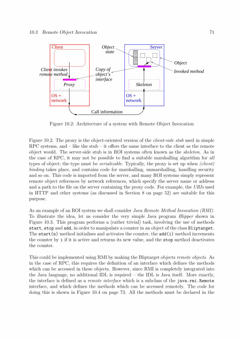
10.3 Remote Object Invocation 71
OS +network
OS +network
��������
��������
Proxy Skeleton
Object
Invoked method
Objectstate
Client invokes Copy ofobject’sinterface
remote method
Call information
Client Server
Figure 10.2: Architecture of a system with Remote Object Invocation
Figure 10.2. The proxy is the object-oriented version of the client-side stub used in simpleRPC systems, and – like the stub – it offers the same interface to the client as the remoteobject would. The server-side stub is in ROI systems often known as the skeleton. As inthe case of RPC, it may not be possible to find a suitable marshalling algorithm for alltypes of object; the type must be serializable. Typically, the proxy is set up when (client)binding takes place, and contains code for marshalling, unmarshalling, handling securityand so on. This code is imported from the server, and many ROI systems simply representremote object references by network references, which specify the server name or addressand a path to the file on the server containing the proxy code. For example, the URIs usedin HTTP and other systems (as discussed in Section 8 on page 52) are suitable for thispurpose.
As an example of an ROI system we shall consider Java Remote Method Invocation (RMI).To illustrate the idea, let us consider the very simple Java program Blipper shown inFigure 10.3. This program performs a (rather trivial) task, involving the use of methodsstart, stop and add, in order to manipulate a counter in an object of the class Bliptarget.The start(n) method initialises and activates the counter, the add(i) method incrementsthe counter by i if it is active and returns its new value, and the stop method deactivatesthe counter.
This could be implemented using RMI by making the Bliptarget objects remote objects. Asin the case of RPC, this requires the definition of an interface which defines the methodswhich can be accessed in these objects. However, since RMI is completely integrated intothe Java language, no additional IDL is required – the IDL is Java itself. More exactly,the interface is defined as a remote interface which is a subclass of the java.rmi.Remote
interface, and which defines the methods which can be accessed remotely. The code fordoing this is shown in Figure 10.4 on page 73. All the methods must be declared in the
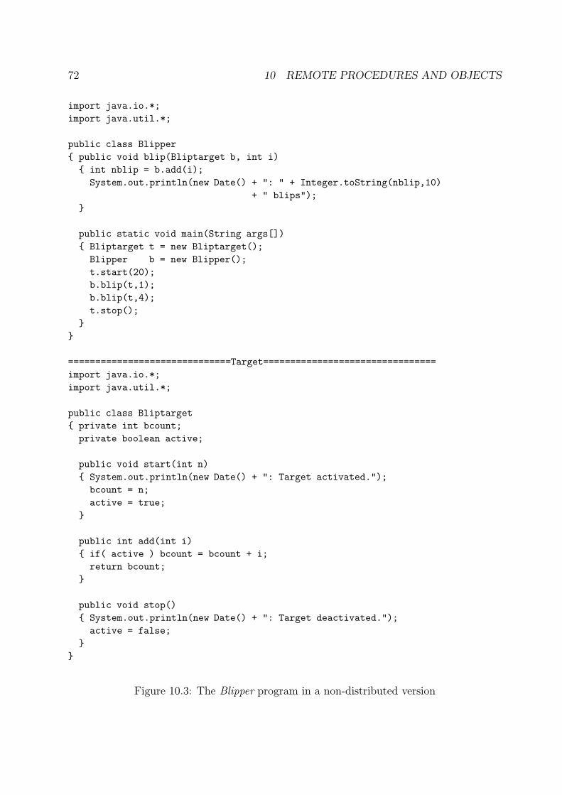
72 10 REMOTE PROCEDURES AND OBJECTS
import java.io.*;
import java.util.*;
public class Blipper
{ public void blip(Bliptarget b, int i)
{ int nblip = b.add(i);
System.out.println(new Date() + ": " + Integer.toString(nblip,10)
+ " blips");
}
public static void main(String args[])
{ Bliptarget t = new Bliptarget();
Blipper b = new Blipper();
t.start(20);
b.blip(t,1);
b.blip(t,4);
t.stop();
}
}
==============================Target================================
import java.io.*;
import java.util.*;
public class Bliptarget
{ private int bcount;
private boolean active;
public void start(int n)
{ System.out.println(new Date() + ": Target activated.");
bcount = n;
active = true;
}
public int add(int i)
{ if( active ) bcount = bcount + i;
return bcount;
}
public void stop()
{ System.out.println(new Date() + ": Target deactivated.");
active = false;
}
}
Figure 10.3: The Blipper program in a non-distributed version
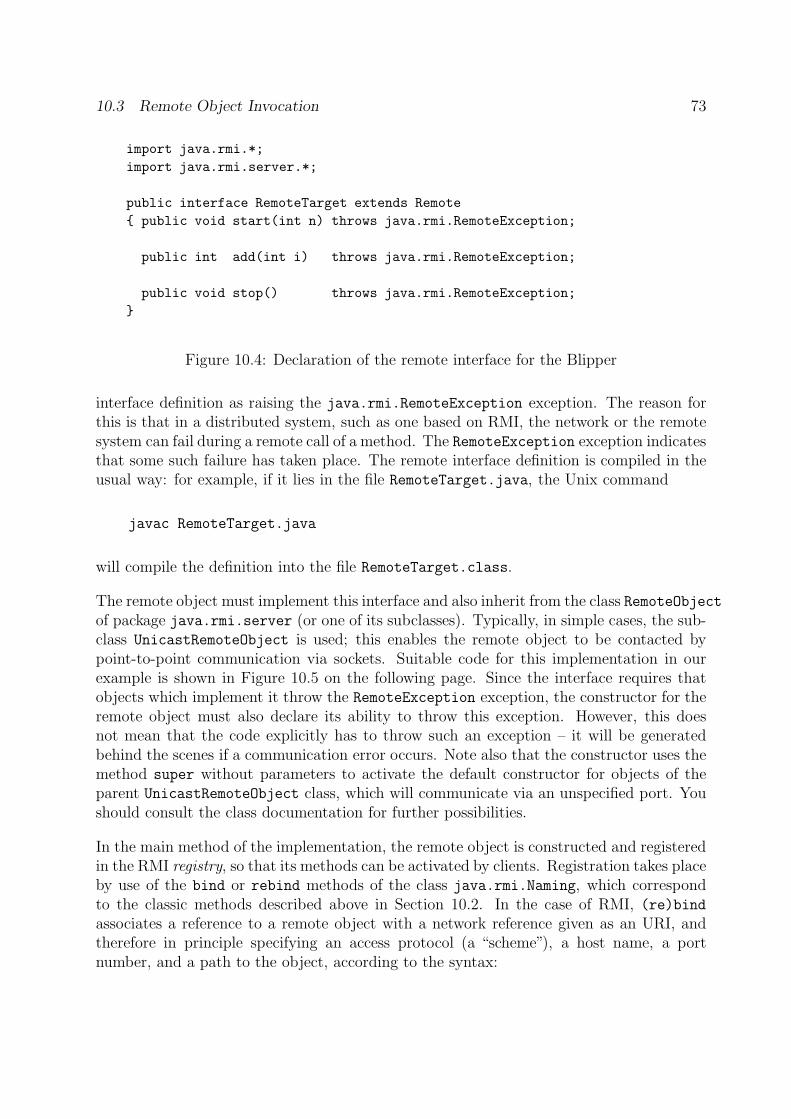
10.3 Remote Object Invocation 73
import java.rmi.*;
import java.rmi.server.*;
public interface RemoteTarget extends Remote
{ public void start(int n) throws java.rmi.RemoteException;
public int add(int i) throws java.rmi.RemoteException;
public void stop() throws java.rmi.RemoteException;
}
Figure 10.4: Declaration of the remote interface for the Blipper
interface definition as raising the java.rmi.RemoteException exception. The reason forthis is that in a distributed system, such as one based on RMI, the network or the remotesystem can fail during a remote call of a method. The RemoteException exception indicatesthat some such failure has taken place. The remote interface definition is compiled in theusual way: for example, if it lies in the file RemoteTarget.java, the Unix command
javac RemoteTarget.java
will compile the definition into the file RemoteTarget.class.
The remote object must implement this interface and also inherit from the class RemoteObjectof package java.rmi.server (or one of its subclasses). Typically, in simple cases, the sub-class UnicastRemoteObject is used; this enables the remote object to be contacted bypoint-to-point communication via sockets. Suitable code for this implementation in ourexample is shown in Figure 10.5 on the following page. Since the interface requires thatobjects which implement it throw the RemoteException exception, the constructor for theremote object must also declare its ability to throw this exception. However, this doesnot mean that the code explicitly has to throw such an exception – it will be generatedbehind the scenes if a communication error occurs. Note also that the constructor uses themethod super without parameters to activate the default constructor for objects of theparent UnicastRemoteObject class, which will communicate via an unspecified port. Youshould consult the class documentation for further possibilities.
In the main method of the implementation, the remote object is constructed and registeredin the RMI registry, so that its methods can be activated by clients. Registration takes placeby use of the bind or rebind methods of the class java.rmi.Naming, which correspondto the classic methods described above in Section 10.2. In the case of RMI, (re)bindassociates a reference to a remote object with a network reference given as an URI, andtherefore in principle specifying an access protocol (a “scheme”), a host name, a portnumber, and a path to the object, according to the syntax:
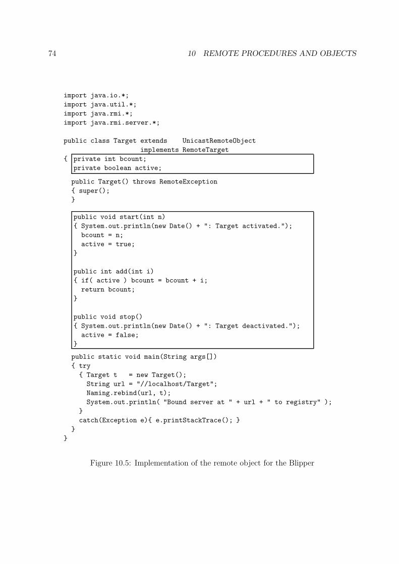
74 10 REMOTE PROCEDURES AND OBJECTS
import java.io.*;
import java.util.*;
import java.rmi.*;
import java.rmi.server.*;
public class Target extends UnicastRemoteObject
implements RemoteTarget
{ private int bcount;
private boolean active;
public Target() throws RemoteException
{ super();
}
public void start(int n)
{ System.out.println(new Date() + ": Target activated.");
bcount = n;
active = true;
}
public int add(int i)
{ if( active ) bcount = bcount + i;
return bcount;
}
public void stop()
{ System.out.println(new Date() + ": Target deactivated.");
active = false;
}
public static void main(String args[])
{ try
{ Target t = new Target();
String url = "//localhost/Target";
Naming.rebind(url, t);
System.out.println( "Bound server at " + url + " to registry" );
}
catch(Exception e){ e.printStackTrace(); }
}
}
Figure 10.5: Implementation of the remote object for the Blipper
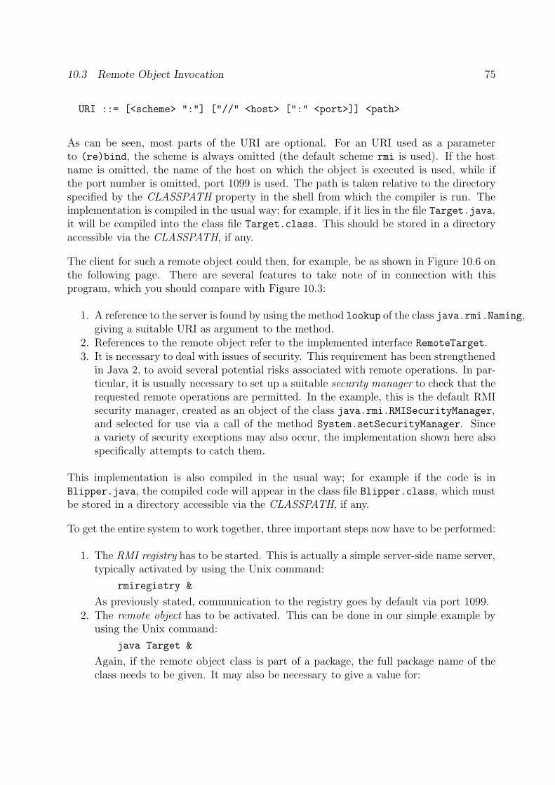
10.3 Remote Object Invocation 75
URI ::= [<scheme> ":"] ["//" <host> [":" <port>]] <path>
As can be seen, most parts of the URI are optional. For an URI used as a parameterto (re)bind, the scheme is always omitted (the default scheme rmi is used). If the hostname is omitted, the name of the host on which the object is executed is used, while ifthe port number is omitted, port 1099 is used. The path is taken relative to the directoryspecified by the CLASSPATH property in the shell from which the compiler is run. Theimplementation is compiled in the usual way; for example, if it lies in the file Target.java,it will be compiled into the class file Target.class. This should be stored in a directoryaccessible via the CLASSPATH, if any.
The client for such a remote object could then, for example, be as shown in Figure 10.6 onthe following page. There are several features to take note of in connection with thisprogram, which you should compare with Figure 10.3:
1. A reference to the server is found by using the method lookup of the class java.rmi.Naming,giving a suitable URI as argument to the method.
2. References to the remote object refer to the implemented interface RemoteTarget.3. It is necessary to deal with issues of security. This requirement has been strengthened
in Java 2, to avoid several potential risks associated with remote operations. In par-ticular, it is usually necessary to set up a suitable security manager to check that therequested remote operations are permitted. In the example, this is the default RMIsecurity manager, created as an object of the class java.rmi.RMISecurityManager,and selected for use via a call of the method System.setSecurityManager. Sincea variety of security exceptions may also occur, the implementation shown here alsospecifically attempts to catch them.
This implementation is also compiled in the usual way; for example if the code is inBlipper.java, the compiled code will appear in the class file Blipper.class, which mustbe stored in a directory accessible via the CLASSPATH, if any.
To get the entire system to work together, three important steps now have to be performed:
1. The RMI registry has to be started. This is actually a simple server-side name server,typically activated by using the Unix command:
rmiregistry &
As previously stated, communication to the registry goes by default via port 1099.2. The remote object has to be activated. This can be done in our simple example by
using the Unix command:
java Target &
Again, if the remote object class is part of a package, the full package name of theclass needs to be given. It may also be necessary to give a value for:
76 10 REMOTE PROCEDURES AND OBJECTS
import java.io.*;
import java.util.*;
import java.rmi.*;
public class Blipper
{ public Target t;
public void blip(RemoteTarget b, int i)
{ try
{ int nblip = b.add(i);
System.out.println(new Date() + ": " + Integer.toString(nblip,10)
+ " blips");
}
catch (RemoteException e) { System.out.println("blip: " + e); }
}
public static void main(String args[])
{ Blipper b = new Blipper();
String server = "localhost";
try
{ if (System.getSecurityManager() == null)
{ System.setSecurityManager(new RMISecurityManager());
};
if (args.length != 0) server = args[0];
String url = "//" + server + "/Target";
RemoteTarget rTarget =
(RemoteTarget) Naming.lookup( url );
rTarget.start(20);
b.blip(rTarget, 1);
b.blip(rTarget, 4);
rTarget.stop();
}
catch (SecurityException e)
{ System.out.println("Blipper: Security exception.");
e.printStackTrace(); }
catch (Exception e)
{ System.out.println("Blipper: Other exception.");
e.printStackTrace(); }
}
}
Figure 10.6: Implementation of an RMI client for the Blipper
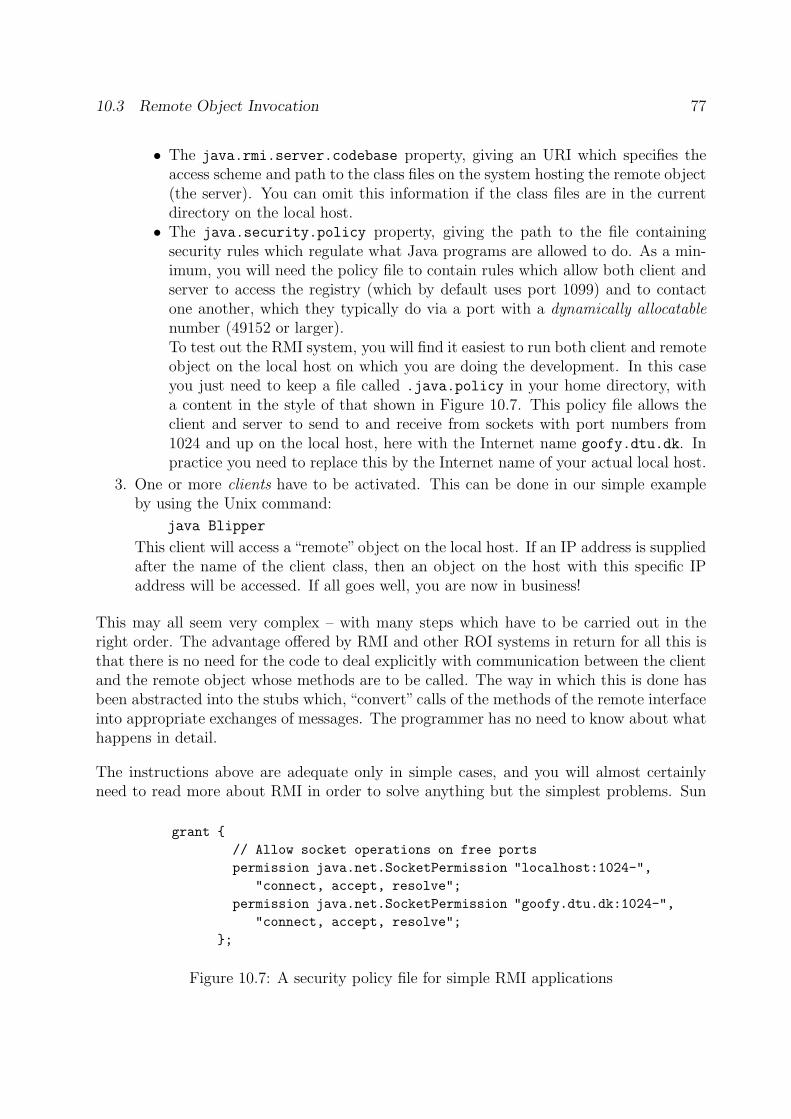
10.3 Remote Object Invocation 77
• The java.rmi.server.codebase property, giving an URI which specifies theaccess scheme and path to the class files on the system hosting the remote object(the server). You can omit this information if the class files are in the currentdirectory on the local host.
• The java.security.policy property, giving the path to the file containingsecurity rules which regulate what Java programs are allowed to do. As a min-imum, you will need the policy file to contain rules which allow both client andserver to access the registry (which by default uses port 1099) and to contactone another, which they typically do via a port with a dynamically allocatablenumber (49152 or larger).To test out the RMI system, you will find it easiest to run both client and remoteobject on the local host on which you are doing the development. In this caseyou just need to keep a file called .java.policy in your home directory, witha content in the style of that shown in Figure 10.7. This policy file allows theclient and server to send to and receive from sockets with port numbers from1024 and up on the local host, here with the Internet name goofy.dtu.dk. Inpractice you need to replace this by the Internet name of your actual local host.
3. One or more clients have to be activated. This can be done in our simple exampleby using the Unix command:
java Blipper
This client will access a “remote”object on the local host. If an IP address is suppliedafter the name of the client class, then an object on the host with this specific IPaddress will be accessed. If all goes well, you are now in business!
This may all seem very complex – with many steps which have to be carried out in theright order. The advantage offered by RMI and other ROI systems in return for all this isthat there is no need for the code to deal explicitly with communication between the clientand the remote object whose methods are to be called. The way in which this is done hasbeen abstracted into the stubs which, “convert” calls of the methods of the remote interfaceinto appropriate exchanges of messages. The programmer has no need to know about whathappens in detail.
The instructions above are adequate only in simple cases, and you will almost certainlyneed to read more about RMI in order to solve anything but the simplest problems. Sun
grant {
// Allow socket operations on free ports
permission java.net.SocketPermission "localhost:1024-",
"connect, accept, resolve";
permission java.net.SocketPermission "goofy.dtu.dk:1024-",
"connect, accept, resolve";
};
Figure 10.7: A security policy file for simple RMI applications
78 11 CORBA
Microsystems have produced a useful tutorial introduction and a FAQ, which you can findon the Web at:
http://java.sun.com/j2se/1.5.0/docs/guide/rmi/hello/hello-world.html
http://java.sun.com/j2se/1.5.0/docs/guide/rmi/faq.html
The tutorial also illustrates how to use RMI in a Windows environment. Further detailsabout security issues are dealt with at:
http://java.sun.com/j2se/1.5.0/docs/guide/security/PolicyFiles.html
http://java.sun.com/j2se/1.5.0/docs/guide/security/permissions.html
Finally, you should note that the instructions above apply to a remote object which (oncestarted) runs continously. Remote objects which are activated when a client request occursare dealt with in:
http://java.sun.com/j2se/1.5.0/docs/guide/rmi/activation/overview.html
11 CORBA
RPC and ROI/RMI introduce a level of abstraction into the software which enables theprogrammer to forget about the details of marshalling, the protocol used to exchange databetween client and server, and other features which were very prominent in the simplenetwork programming approach. In this section we shall look at a further approach toprogramming network applications which introduces even more abstraction into the soft-ware, by offering a software environment which can operate with software componentsirrespective of their implementation language.
CORBA is a software architecture and environment for developing and implementing dis-tributed applications, which has been developed by a consortium known as the ObjectManagement Group (OMG), and is now widely accepted as an industry standard. Thecurrent version of CORBA is version 2.3.1 [32]. The acronym CORBA stands for CommonObject Request Broker Architecture, where the Object Request Broker (ORB for short)refers to a “software bus” which can be used to connect many different kinds of softwarecomponent in a software system. The same approach to software system design, some-times known as component-based programming, lies behind Microsoft’s proprietary DCOMarchitecture. The CORBA documentation explains how these two systems can interwork.
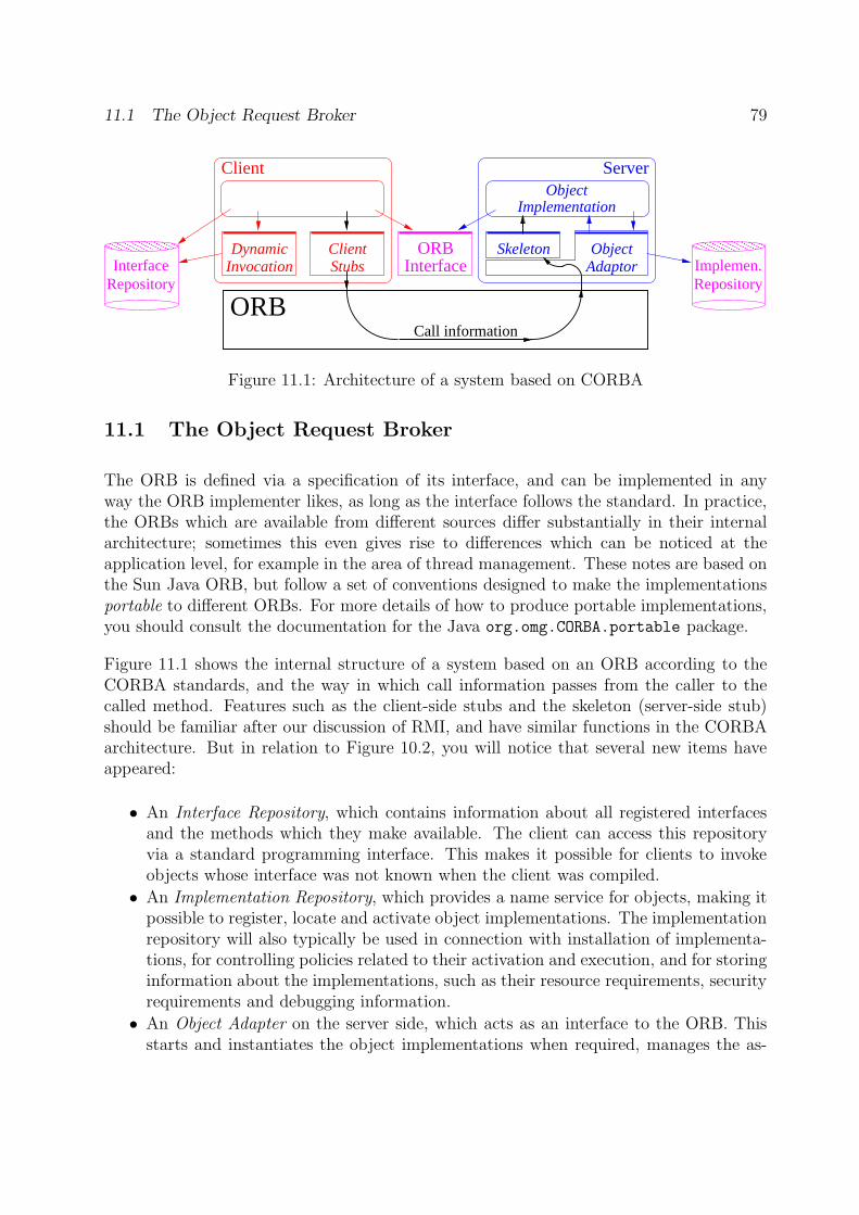
11.1 The Object Request Broker 79
��������������������
InterfaceRepository
��������������������ORB
InterfaceRepositoryImplemen.
Client Server
InvocationDynamic Client
StubsSkeleton Object
Adaptor
ObjectImplementation
Call informationORB
Figure 11.1: Architecture of a system based on CORBA
11.1 The Object Request Broker
The ORB is defined via a specification of its interface, and can be implemented in anyway the ORB implementer likes, as long as the interface follows the standard. In practice,the ORBs which are available from different sources differ substantially in their internalarchitecture; sometimes this even gives rise to differences which can be noticed at theapplication level, for example in the area of thread management. These notes are based onthe Sun Java ORB, but follow a set of conventions designed to make the implementationsportable to different ORBs. For more details of how to produce portable implementations,you should consult the documentation for the Java org.omg.CORBA.portable package.
Figure 11.1 shows the internal structure of a system based on an ORB according to theCORBA standards, and the way in which call information passes from the caller to thecalled method. Features such as the client-side stubs and the skeleton (server-side stub)should be familiar after our discussion of RMI, and have similar functions in the CORBAarchitecture. But in relation to Figure 10.2, you will notice that several new items haveappeared:
• An Interface Repository, which contains information about all registered interfacesand the methods which they make available. The client can access this repositoryvia a standard programming interface. This makes it possible for clients to invokeobjects whose interface was not known when the client was compiled.
• An Implementation Repository, which provides a name service for objects, making itpossible to register, locate and activate object implementations. The implementationrepository will also typically be used in connection with installation of implementa-tions, for controlling policies related to their activation and execution, and for storinginformation about the implementations, such as their resource requirements, securityrequirements and debugging information.
• An Object Adapter on the server side, which acts as an interface to the ORB. Thisstarts and instantiates the object implementations when required, manages the as-
80 11 CORBA
signment of unique references to new object instances and passes calls up to theimplementations. In principle, an ORB implementation can offer several objectadapters, but in CORBA version 2.3 there is a preferred object adapter for stan-dard use known as the Portable Object Adapter (POA), which is designed specificallyfor use with multiple ORB implementations. We shall discuss the POA in more detailbelow.
• A Dynamic Invocation Interface (DII), which (in contrast to a stub) allows the clientto activate a method in an object whose interface was not known at compile time.
Finally, both the client and the server have direct access to the ORB via an ORB interface,used primarily for starting and initialising the ORB.
An important feature of CORBA which is not explicitly shown in Figure 11.1 is that avariety of services which are useful to many applications have been defined as part of theproject of developing the CORBA framework. These are generally known as CommonObject Services (COS), and include such services as:
Naming Service: for registration of bindings between names and object references.
Event Service: for dealing with asynchronous events in CORBA-based systems, allow-ing components on the ORB to register and de-register their interest in receivingparticular events.
Security Service: which provides security facilities, such as authentication, non-repudiationand audit trails.
Concurrency Service: which provides a lock manager.
Time Service: which offers a service for clock synchronisation over multiple computers,a feature necessary for accurate timestamping in distributed applications.
Like all other CORBA services, these appear as objects with specified interfaces, accessedvia the ORB.
11.2 CORBA Interfaces and the CORBA IDL
As in the case of RPC and RMI, it is necessary to define an interface which the serverpresents to its clients. Once again, this interface is defined using an IDL, in this case onespecially designed for use with CORBA. This CORBA IDL has a syntax based on C++,with well-defined mappings of the IDL’s types, constants and exceptions to constructs ina range of implementation languages such as C++ itself, Java, C, SmallTalk, Cobol andother languages. This makes CORBA especially valuable for developing applications wheredifferent parts of the application software have been (or will be) implemented in differentlanguages. In these notes, we shall confine our attention to the CORBA IDL to Java map-ping. For details of other mappings, you need to consult the CORBA documentation [32].
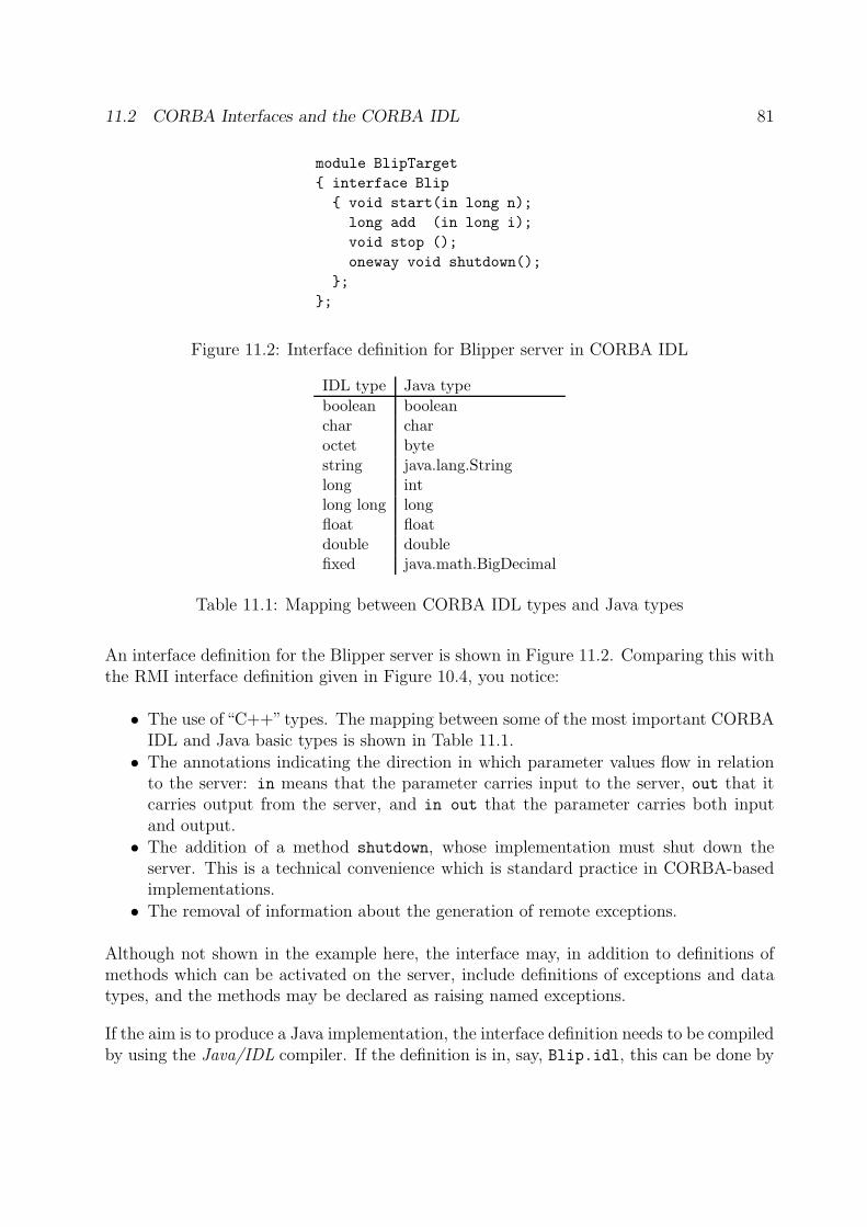
11.2 CORBA Interfaces and the CORBA IDL 81
module BlipTarget
{ interface Blip
{ void start(in long n);
long add (in long i);
void stop ();
oneway void shutdown();
};
};
Figure 11.2: Interface definition for Blipper server in CORBA IDL
IDL type Java type
boolean booleanchar charoctet bytestring java.lang.Stringlong intlong long longfloat floatdouble doublefixed java.math.BigDecimal
Table 11.1: Mapping between CORBA IDL types and Java types
An interface definition for the Blipper server is shown in Figure 11.2. Comparing this withthe RMI interface definition given in Figure 10.4, you notice:
• The use of “C++”types. The mapping between some of the most important CORBAIDL and Java basic types is shown in Table 11.1.
• The annotations indicating the direction in which parameter values flow in relationto the server: in means that the parameter carries input to the server, out that itcarries output from the server, and in out that the parameter carries both inputand output.
• The addition of a method shutdown, whose implementation must shut down theserver. This is a technical convenience which is standard practice in CORBA-basedimplementations.
• The removal of information about the generation of remote exceptions.
Although not shown in the example here, the interface may, in addition to definitions ofmethods which can be activated on the server, include definitions of exceptions and datatypes, and the methods may be declared as raising named exceptions.
If the aim is to produce a Java implementation, the interface definition needs to be compiledby using the Java/IDL compiler. If the definition is in, say, Blip.idl, this can be done by
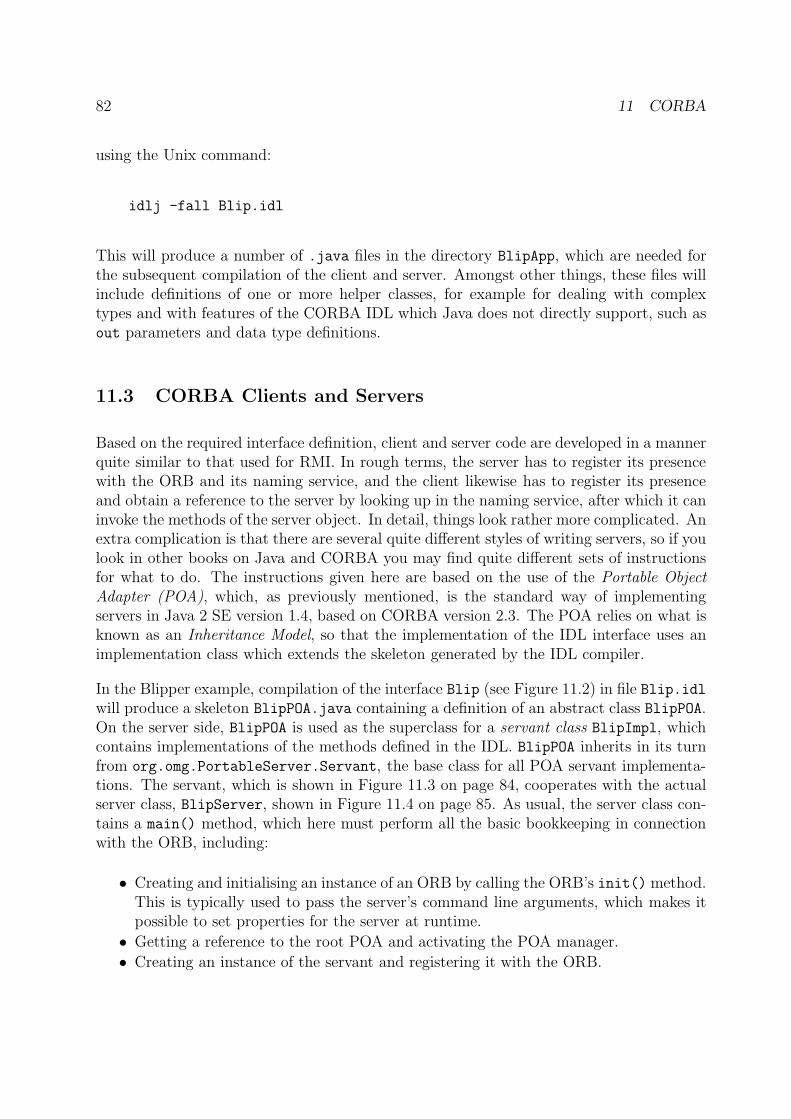
82 11 CORBA
using the Unix command:
idlj -fall Blip.idl
This will produce a number of .java files in the directory BlipApp, which are needed forthe subsequent compilation of the client and server. Amongst other things, these files willinclude definitions of one or more helper classes, for example for dealing with complextypes and with features of the CORBA IDL which Java does not directly support, such asout parameters and data type definitions.
11.3 CORBA Clients and Servers
Based on the required interface definition, client and server code are developed in a mannerquite similar to that used for RMI. In rough terms, the server has to register its presencewith the ORB and its naming service, and the client likewise has to register its presenceand obtain a reference to the server by looking up in the naming service, after which it caninvoke the methods of the server object. In detail, things look rather more complicated. Anextra complication is that there are several quite different styles of writing servers, so if youlook in other books on Java and CORBA you may find quite different sets of instructionsfor what to do. The instructions given here are based on the use of the Portable ObjectAdapter (POA), which, as previously mentioned, is the standard way of implementingservers in Java 2 SE version 1.4, based on CORBA version 2.3. The POA relies on what isknown as an Inheritance Model, so that the implementation of the IDL interface uses animplementation class which extends the skeleton generated by the IDL compiler.
In the Blipper example, compilation of the interface Blip (see Figure 11.2) in file Blip.idlwill produce a skeleton BlipPOA.java containing a definition of an abstract class BlipPOA.On the server side, BlipPOA is used as the superclass for a servant class BlipImpl, whichcontains implementations of the methods defined in the IDL. BlipPOA inherits in its turnfrom org.omg.PortableServer.Servant, the base class for all POA servant implementa-tions. The servant, which is shown in Figure 11.3 on page 84, cooperates with the actualserver class, BlipServer, shown in Figure 11.4 on page 85. As usual, the server class con-tains a main() method, which here must perform all the basic bookkeeping in connectionwith the ORB, including:
• Creating and initialising an instance of an ORB by calling the ORB’s init() method.This is typically used to pass the server’s command line arguments, which makes itpossible to set properties for the server at runtime.
• Getting a reference to the root POA and activating the POA manager.
• Creating an instance of the servant and registering it with the ORB.
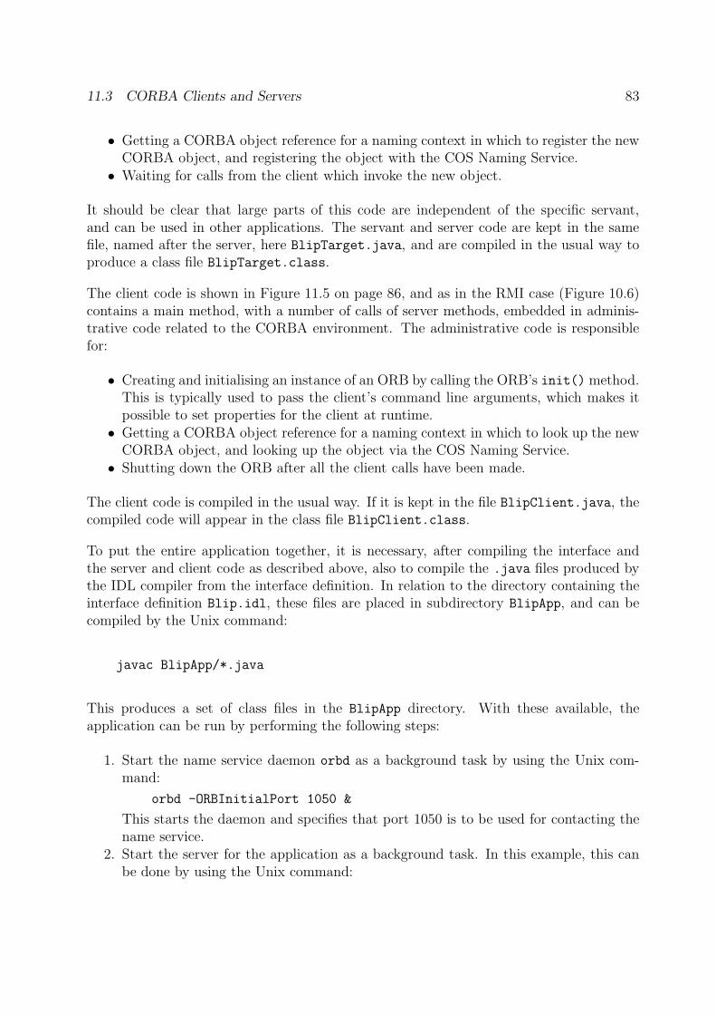
11.3 CORBA Clients and Servers 83
• Getting a CORBA object reference for a naming context in which to register the newCORBA object, and registering the object with the COS Naming Service.
• Waiting for calls from the client which invoke the new object.
It should be clear that large parts of this code are independent of the specific servant,and can be used in other applications. The servant and server code are kept in the samefile, named after the server, here BlipTarget.java, and are compiled in the usual way toproduce a class file BlipTarget.class.
The client code is shown in Figure 11.5 on page 86, and as in the RMI case (Figure 10.6)contains a main method, with a number of calls of server methods, embedded in adminis-trative code related to the CORBA environment. The administrative code is responsiblefor:
• Creating and initialising an instance of an ORB by calling the ORB’s init() method.This is typically used to pass the client’s command line arguments, which makes itpossible to set properties for the client at runtime.
• Getting a CORBA object reference for a naming context in which to look up the newCORBA object, and looking up the object via the COS Naming Service.
• Shutting down the ORB after all the client calls have been made.
The client code is compiled in the usual way. If it is kept in the file BlipClient.java, thecompiled code will appear in the class file BlipClient.class.
To put the entire application together, it is necessary, after compiling the interface andthe server and client code as described above, also to compile the .java files produced bythe IDL compiler from the interface definition. In relation to the directory containing theinterface definition Blip.idl, these files are placed in subdirectory BlipApp, and can becompiled by the Unix command:
javac BlipApp/*.java
This produces a set of class files in the BlipApp directory. With these available, theapplication can be run by performing the following steps:
1. Start the name service daemon orbd as a background task by using the Unix com-mand:
orbd -ORBInitialPort 1050 &
This starts the daemon and specifies that port 1050 is to be used for contacting thename service.
2. Start the server for the application as a background task. In this example, this canbe done by using the Unix command:
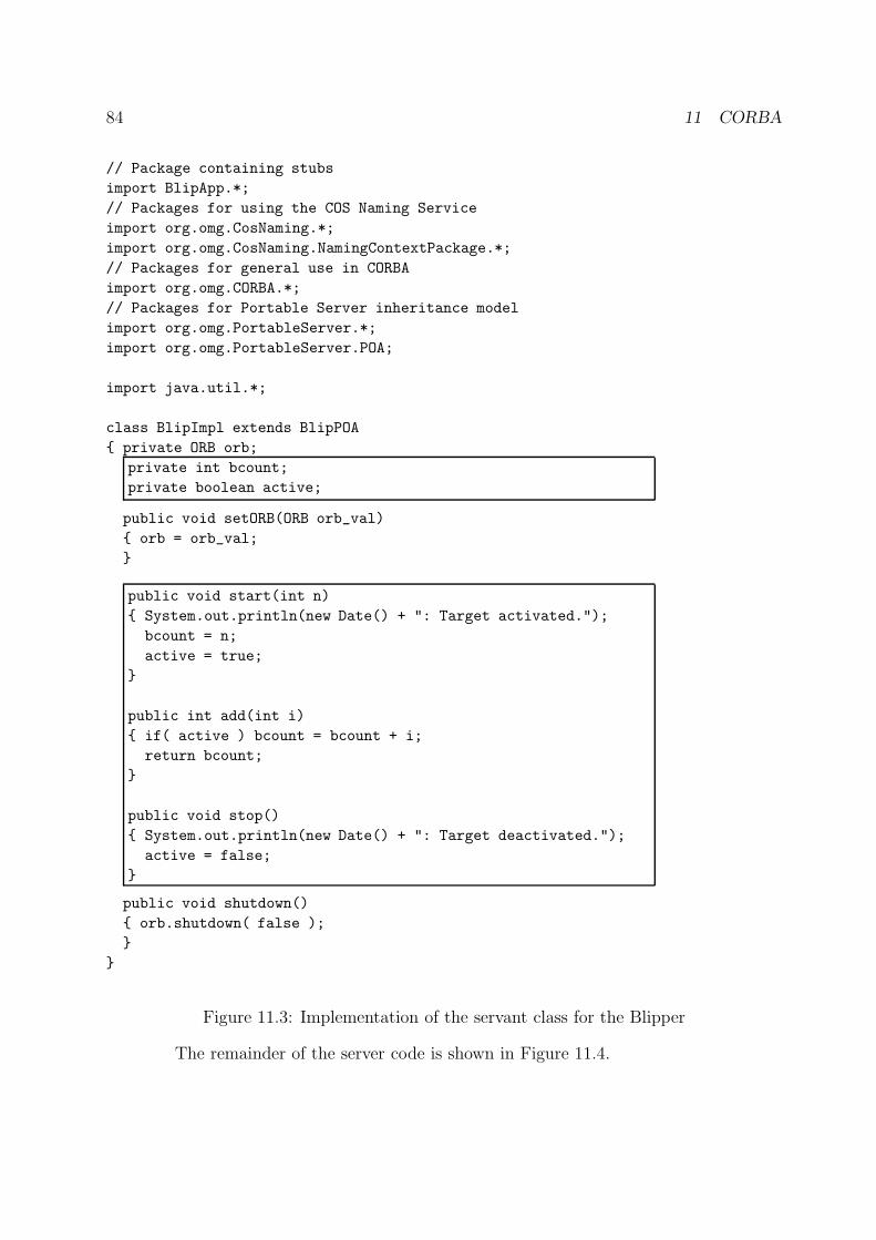
84 11 CORBA
// Package containing stubs
import BlipApp.*;
// Packages for using the COS Naming Service
import org.omg.CosNaming.*;
import org.omg.CosNaming.NamingContextPackage.*;
// Packages for general use in CORBA
import org.omg.CORBA.*;
// Packages for Portable Server inheritance model
import org.omg.PortableServer.*;
import org.omg.PortableServer.POA;
import java.util.*;
class BlipImpl extends BlipPOA
{ private ORB orb;
private int bcount;
private boolean active;
public void setORB(ORB orb_val)
{ orb = orb_val;
}
public void start(int n)
{ System.out.println(new Date() + ": Target activated.");
bcount = n;
active = true;
}
public int add(int i)
{ if( active ) bcount = bcount + i;
return bcount;
}
public void stop()
{ System.out.println(new Date() + ": Target deactivated.");
active = false;
}
public void shutdown()
{ orb.shutdown( false );
}
}
Figure 11.3: Implementation of the servant class for the Blipper
The remainder of the server code is shown in Figure 11.4.
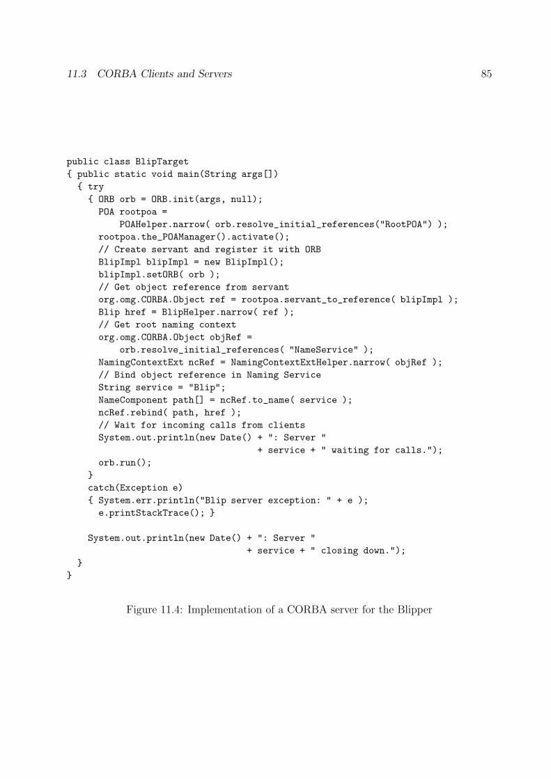
11.3 CORBA Clients and Servers 85
public class BlipTarget
{ public static void main(String args[])
{ try
{ ORB orb = ORB.init(args, null);
POA rootpoa =
POAHelper.narrow( orb.resolve_initial_references("RootPOA") );
rootpoa.the_POAManager().activate();
// Create servant and register it with ORB
BlipImpl blipImpl = new BlipImpl();
blipImpl.setORB( orb );
// Get object reference from servant
org.omg.CORBA.Object ref = rootpoa.servant_to_reference( blipImpl );
Blip href = BlipHelper.narrow( ref );
// Get root naming context
org.omg.CORBA.Object objRef =
orb.resolve_initial_references( "NameService" );
NamingContextExt ncRef = NamingContextExtHelper.narrow( objRef );
// Bind object reference in Naming Service
String service = "Blip";
NameComponent path[] = ncRef.to_name( service );
ncRef.rebind( path, href );
// Wait for incoming calls from clients
System.out.println(new Date() + ": Server "
+ service + " waiting for calls.");
orb.run();
}
catch(Exception e)
{ System.err.println("Blip server exception: " + e );
e.printStackTrace(); }
System.out.println(new Date() + ": Server "
+ service + " closing down.");
}
}
Figure 11.4: Implementation of a CORBA server for the Blipper
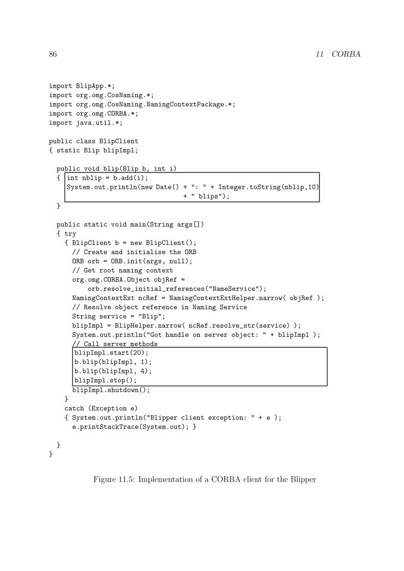
86 11 CORBA
import BlipApp.*;
import org.omg.CosNaming.*;
import org.omg.CosNaming.NamingContextPackage.*;
import org.omg.CORBA.*;
import java.util.*;
public class BlipClient
{ static Blip blipImpl;
public void blip(Blip b, int i)
{ int nblip = b.add(i);
System.out.println(new Date() + ": " + Integer.toString(nblip,10)
+ " blips");
}
public static void main(String args[])
{ try
{ BlipClient b = new BlipClient();
// Create and initialise the ORB
ORB orb = ORB.init(args, null);
// Get root naming context
org.omg.CORBA.Object objRef =
orb.resolve_initial_references("NameService");
NamingContextExt ncRef = NamingContextExtHelper.narrow( objRef );
// Resolve object reference in Naming Service
String service = "Blip";
blipImpl = BlipHelper.narrow( ncRef.resolve_str(service) );
System.out.println("Got handle on server object: " + blipImpl );
// Call server methods
blipImpl.start(20);
b.blip(blipImpl, 1);
b.blip(blipImpl, 4);
blipImpl.stop();
blipImpl.shutdown();
}
catch (Exception e)
{ System.out.println("Blipper client exception: " + e );
e.printStackTrace(System.out); }
}
}
Figure 11.5: Implementation of a CORBA client for the Blipper
11.3 CORBA Clients and Servers 87
java BlipTarget -ORBInitialPort 1050 -ORBInitialHost localhost &
This is appropriate if the name server is running on same machine as the Blip server.If the name server is to run on a remote host, the name of this host should besubstituted for localhost.
3. Start the client. In this example, this can be done by using the Unix command:
java BlipClient -ORBInitialPort 1050 -ORBInitialHost localhost
As in the case of the server, this is appropriate if the name server is running on thesame machine as the Blip client. If the name server is to run on a remote host, thename of this host should be substituted for localhost.
4. When the client has finished running, it will close the ORB down by invoking theshutdown(false) method. However, this still leaves the name server demon orbd
running, waiting for things to do. You must explicitly kill the Unix process whichis running the name server: Use the Unix ps command to look up the number ofthe orbd process, then kill the process explicitly, for example by using the Unixcommand:
kill -9 12345
where 12345 (or whatever) is the number of the process.
As with RMI, you may like (or need) to find out more details about how to use CORBAin connection with Java. However, you need to be careful what you read: Although thereare several books on the subject, many of them are not up to date, because they deal withhow to use older versions of Java, or older versions of CORBA, or other techniques forimplementing the server-side code. A current tutorial and a glossary of terms can be foundon the Web at:
http://java.sun.com/j2se/1.5.0/docs/guide/idl/jidlExample.html
http://java.sun.com/j2se/1.5.0/docs/guide/idl/jidlGlossary.html
These contain a number of links to further material on CORBA, the CORBA-to-Javamapping and other useful topics.
This short presentation of CORBA has focussed on using CORBA in the classic manner,with interfaces described in the CORBA IDL, and using standard CORBA tools for pro-ducing an implementation in a particular programming language, in this case Java. This isnot the only approach to combining CORBA and Java. One common alternative is to usethe RMI-based Internet Inter-ORB Protocol, usually known as RMI-IIOP, which makes itpossible to program using RMI conventions, but to use IIOP as the underlying transportmechanism. RMI-IIOP provides interoperability with other CORBA objects implementedin various languages if all the remote interfaces are defined as Java RMI interfaces. Doc-umentation on RMI-IIOP and a tutorial covering this approach can be found on the Webat:
http://java.sun.com/j2se/1.5.0/docs/guide/rmi-iiop/index.html
http://java.sun.com/j2se/1.5.0/docs/guide/rmi-iiop/rmiiiopexample.html
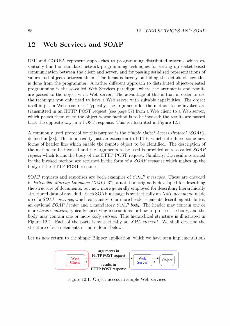
88 12 WEB SERVICES AND SOAP
12 Web Services and SOAP
RMI and CORBA represent approaches to programming distributed systems which es-sentially build on standard network programming techniques for setting up socket-basedcommunication between the client and server, and for passing serialised representations ofvalues and objects between them. The focus is largely on hiding the details of how thisis done from the programmer. A rather different approach to distributed object-orientedprogramming is the so-called Web Services paradigm, where the arguments and resultsare passed to the object via a Web server. The advantage of this is that in order to usethe technique you only need to have a Web server with suitable capabilities. The objectitself is just a Web resource. Typically, the arguments for the method to be invoked aretransmitted in an HTTP POST request (see page 57) from a Web client to a Web server,which passes them on to the object whose method is to be invoked; the results are passedback the opposite way in a POST response. This is illustrated in Figure 12.1.
A commonly used protocol for this purpose is the Simple Object Access Protocol (SOAP),defined in [38]. This is in reality just an extension to HTTP, which introduces some newforms of header line which enable the remote object to be identified. The description ofthe method to be invoked and the arguments to be used is provided as a so-called SOAPrequest which forms the body of the HTTP POST request. Similarly, the results returnedby the invoked method are returned in the form of a SOAP response which makes up thebody of the HTTP POST response.
SOAP requests and responses are both examples of SOAP messages. These are encodedin Extensible Markup Language (XML) [37], a notation originally developed for describingthe structure of documents, but now more generally employed for describing hierarchicallystructured data of any kind. Each SOAP message is syntactically an XML document, madeup of a SOAP envelope, which contains zero or more header elements describing attributes,an optional SOAP header and a mandatory SOAP body. The header may contain one ormore header entries, typically specifying instructions for how to process the body, and thebody may contain one or more body entries. This hierarchical structure is illustrated inFigure 12.2. Each of the parts is syntactically an XML element. We shall describe thestructure of such elements in more detail below.
Let us now return to the simple Blipper application, which we have seen implementations
ClientWeb
ServerWeb Object
HTTP POST response
HTTP POST request
results in
arguments in
Figure 12.1: Object access in simple Web services
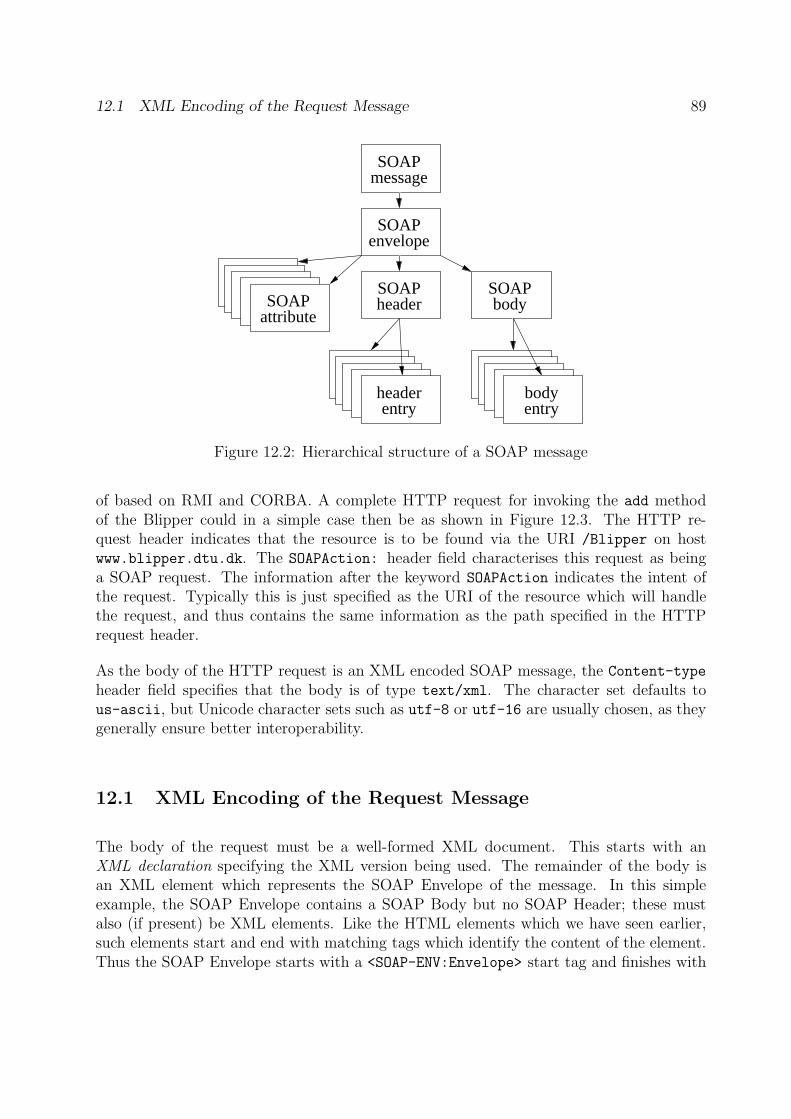
12.1 XML Encoding of the Request Message 89
SOAPmessage
SOAPheader
SOAPbody
SOAPenvelope
headerentry
headerentry
headerentry
headerentry
headerentry
headerentry
headerentry
headerentry
headerentry
headerentry
headerentry
headerentry
headerentry
SOAPattribute
entrybody
Figure 12.2: Hierarchical structure of a SOAP message
of based on RMI and CORBA. A complete HTTP request for invoking the add methodof the Blipper could in a simple case then be as shown in Figure 12.3. The HTTP re-quest header indicates that the resource is to be found via the URI /Blipper on hostwww.blipper.dtu.dk. The SOAPAction: header field characterises this request as beinga SOAP request. The information after the keyword SOAPAction indicates the intent ofthe request. Typically this is just specified as the URI of the resource which will handlethe request, and thus contains the same information as the path specified in the HTTPrequest header.
As the body of the HTTP request is an XML encoded SOAP message, the Content-type
header field specifies that the body is of type text/xml. The character set defaults tous-ascii, but Unicode character sets such as utf-8 or utf-16 are usually chosen, as theygenerally ensure better interoperability.
12.1 XML Encoding of the Request Message
The body of the request must be a well-formed XML document. This starts with anXML declaration specifying the XML version being used. The remainder of the body isan XML element which represents the SOAP Envelope of the message. In this simpleexample, the SOAP Envelope contains a SOAP Body but no SOAP Header; these mustalso (if present) be XML elements. Like the HTML elements which we have seen earlier,such elements start and end with matching tags which identify the content of the element.Thus the SOAP Envelope starts with a <SOAP-ENV:Envelope> start tag and finishes with
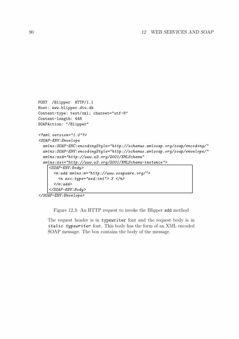
90 12 WEB SERVICES AND SOAP
POST /Blipper HTTP/1.1
Host: www.blipper.dtu.dk
Content-type: text/xml; charset="utf-8"
Content-length: 448
SOAPAction: "/Blipper"
<?xml version="1.0"?>
<SOAP-ENV:Envelope
xmlns:SOAP-ENC:encodingStyle="http://schemas.xmlsoap.org/soap/encoding/"
xmlns:SOAP-ENV:encodingStyle="http://schemas.xmlsoap.org/soap/envelope/"
xmlns:xsd="http://www.w3.org/2001/XMLSchema"
xmlns:xsi="http://www.w3.org/2001/XMLSchema-instance">
<SOAP-ENV:Body>
<m:add xmlns:m="http://www.soapware.org/">
<n xsi:type="xsd:int"> 3 </n>
</m:add>
</SOAP-ENV:Body>
</SOAP-ENV:Envelope>
Figure 12.3: An HTTP request to invoke the Blipper add method
The request header is in typewriter font and the request body is initalic typewriter font. This body has the form of an XML encodedSOAP message. The box contains the body of the message.
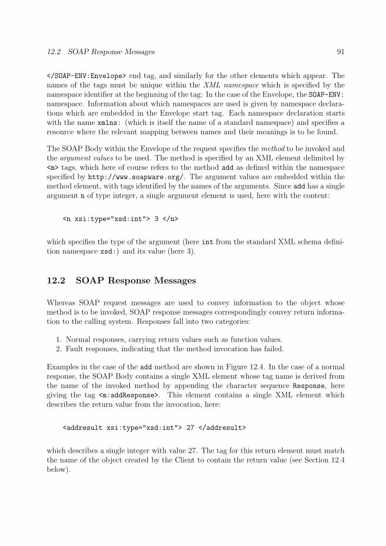
12.2 SOAP Response Messages 91
</SOAP-ENV:Envelope> end tag, and similarly for the other elements which appear. Thenames of the tags must be unique within the XML namespace which is specified by thenamespace identifier at the beginning of the tag: In the case of the Envelope, the SOAP-ENV:namespace. Information about which namespaces are used is given by namespace declara-tions which are embedded in the Envelope start tag. Each namespace declaration startswith the name xmlns: (which is itself the name of a standard namespace) and specifies aresource where the relevant mapping between names and their meanings is to be found.
The SOAP Body within the Envelope of the request specifies the method to be invoked andthe argument values to be used. The method is specified by an XML element delimited by<m> tags, which here of course refers to the method add as defined within the namespacespecified by http://www.soapware.org/. The argument values are embedded within themethod element, with tags identified by the names of the arguments. Since add has a singleargument n of type integer, a single argument element is used, here with the content:
<n xsi:type="xsd:int"> 3 </n>
which specifies the type of the argument (here int from the standard XML schema defini-tion namespace xsd:) and its value (here 3).
12.2 SOAP Response Messages
Whereas SOAP request messages are used to convey information to the object whosemethod is to be invoked, SOAP response messages correspondingly convey return informa-tion to the calling system. Responses fall into two categories:
1. Normal responses, carrying return values such as function values.2. Fault responses, indicating that the method invocation has failed.
Examples in the case of the add method are shown in Figure 12.4. In the case of a normalresponse, the SOAP Body contains a single XML element whose tag name is derived fromthe name of the invoked method by appending the character sequence Response, heregiving the tag <m:addResponse>. This element contains a single XML element whichdescribes the return value from the invocation, here:
<addresult xsi:type="xsd:int"> 27 </addresult>
which describes a single integer with value 27. The tag for this return element must matchthe name of the object created by the Client to contain the return value (see Section 12.4below).
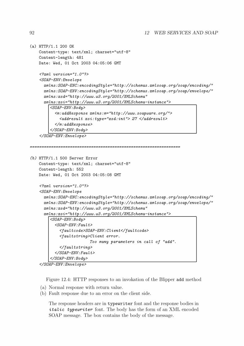
92 12 WEB SERVICES AND SOAP
(a) HTTP/1.1 200 OK
Content-type: text/xml; charset="utf-8"
Content-length: 481
Date: Wed, 01 Oct 2003 04:05:06 GMT
<?xml version="1.0"?>
<SOAP-ENV:Envelope
xmlns:SOAP-ENC:encodingStyle="http://schemas.xmlsoap.org/soap/encoding/"
xmlns:SOAP-ENV:encodingStyle="http://schemas.xmlsoap.org/soap/envelope/"
xmlns:xsd="http://www.w3.org/2001/XMLSchema"
xmlns:xsi="http://www.w3.org/2001/XMLSchema-instance">
<SOAP-ENV:Body>
<m:addResponse xmlns:m="http://www.soapware.org/">
<addresult xsi:type="xsd:int"> 27 </addresult>
</m:addResponse>
</SOAP-ENV:Body>
</SOAP-ENV:Envelope>
================================================================
(b) HTTP/1.1 500 Server Error
Content-type: text/xml; charset="utf-8"
Content-length: 552
Date: Wed, 01 Oct 2003 04:05:08 GMT
<?xml version="1.0"?>
<SOAP-ENV:Envelope
xmlns:SOAP-ENC:encodingStyle="http://schemas.xmlsoap.org/soap/encoding/"
xmlns:SOAP-ENV:encodingStyle="http://schemas.xmlsoap.org/soap/envelope/"
xmlns:xsd="http://www.w3.org/2001/XMLSchema"
xmlns:xsi="http://www.w3.org/2001/XMLSchema-instance">
<SOAP-ENV:Body>
<SOAP-ENV:Fault>
<faultcode>SOAP-ENV:Client</faultcode>
<faultstring>Client error.
Too many parameters in call of "add".
</faultstring>
</SOAP-ENV:Fault>
</SOAP-ENV:Body>
</SOAP-ENV:Envelope>
Figure 12.4: HTTP responses to an invokation of the Blipper add method
(a) Normal response with return value.(b) Fault response due to an error on the client side.
The response headers are in typewriter font and the response bodies initalic typewriter font. The body has the form of an XML encodedSOAP message. The box contains the body of the message.
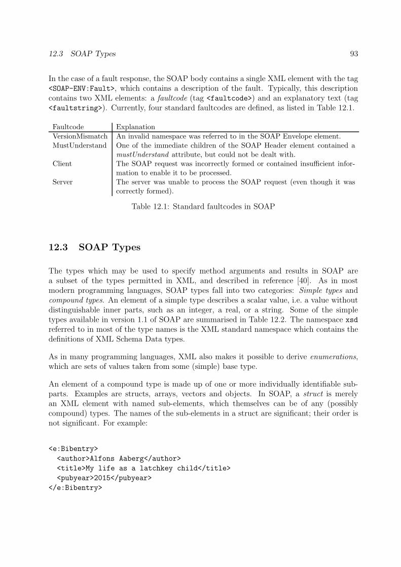
12.3 SOAP Types 93
In the case of a fault response, the SOAP body contains a single XML element with the tag<SOAP-ENV:Fault>, which contains a description of the fault. Typically, this descriptioncontains two XML elements: a faultcode (tag <faultcode>) and an explanatory text (tag<faultstring>). Currently, four standard faultcodes are defined, as listed in Table 12.1.
Faultcode Explanation
VersionMismatch An invalid namespace was referred to in the SOAP Envelope element.MustUnderstand One of the immediate children of the SOAP Header element contained a
mustUnderstand attribute, but could not be dealt with.Client The SOAP request was incorrectly formed or contained insufficient infor-
mation to enable it to be processed.Server The server was unable to process the SOAP request (even though it was
correctly formed).
Table 12.1: Standard faultcodes in SOAP
12.3 SOAP Types
The types which may be used to specify method arguments and results in SOAP area subset of the types permitted in XML, and described in reference [40]. As in mostmodern programming languages, SOAP types fall into two categories: Simple types andcompound types. An element of a simple type describes a scalar value, i.e. a value withoutdistinguishable inner parts, such as an integer, a real, or a string. Some of the simpletypes available in version 1.1 of SOAP are summarised in Table 12.2. The namespace xsd
referred to in most of the type names is the XML standard namespace which contains thedefinitions of XML Schema Data types.
As in many programming languages, XML also makes it possible to derive enumerations,which are sets of values taken from some (simple) base type.
An element of a compound type is made up of one or more individually identifiable sub-parts. Examples are structs, arrays, vectors and objects. In SOAP, a struct is merelyan XML element with named sub-elements, which themselves can be of any (possiblycompound) types. The names of the sub-elements in a struct are significant; their order isnot significant. For example:
<e:Bibentry>
<author>Alfons Aaberg</author>
<title>My life as a latchkey child</title>
<pubyear>2015</pubyear>
</e:Bibentry>
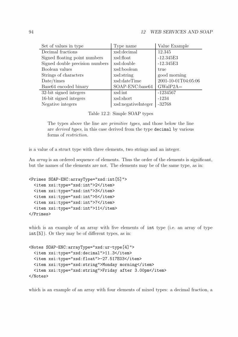
94 12 WEB SERVICES AND SOAP
Set of values in type Type name Value ExampleDecimal fractions xsd:decimal 12.345Signed floating point numbers xsd:float -12.345E3Signed double precision numbers xsd:double -12.345E3Boolean values xsd:boolean trueStrings of characters xsd:string good morningDate/times xsd:dateTime 2001-10-01T04:05:06Base64 encoded binary SOAP-ENC:base64 GWalP2A=32-bit signed integers xsd:int -123456716-bit signed integers xsd:short -1234Negative integers xsd:negativeInteger -32768
Table 12.2: Simple SOAP types
The types above the line are primitive types, and those below the lineare derived types, in this case derived from the type decimal by variousforms of restriction.
is a value of a struct type with three elements, two strings and an integer.
An array is an ordered sequence of elements. Thus the order of the elements is significant,but the names of the elements are not. The elements may be of the same type, as in:
<Primes SOAP-ENC:arrayType="xsd:int[5]">
<item xsi:type="xsd:int">2</item>
<item xsi:type="xsd:int">3</item>
<item xsi:type="xsd:int">5</item>
<item xsi:type="xsd:int">7</item>
<item xsi:type="xsd:int">11</item>
</Primes>
which is an example of an array with five elements of int type (i.e. an array of typeint[5]). Or they may be of different types, as in:
<Notes SOAP-ENC:arrayType="xsd:ur-type[4]">
<item xsi:type="xsd:decimal">11.3</item>
<item xsi:type="xsd:float">-27.517E03</item>
<item xsi:type="xsd:string">Monday morning</item>
<item xsi:type="xsd:string">Friday after 3.00pm</item>
</Notes>
which is an example of an array with four elements of mixed types: a decimal fraction, a
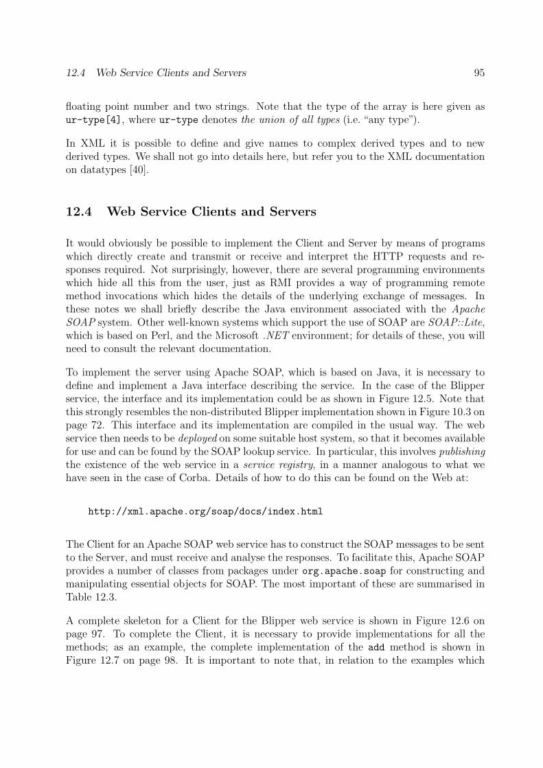
12.4 Web Service Clients and Servers 95
floating point number and two strings. Note that the type of the array is here given asur-type[4], where ur-type denotes the union of all types (i.e. “any type”).
In XML it is possible to define and give names to complex derived types and to newderived types. We shall not go into details here, but refer you to the XML documentationon datatypes [40].
12.4 Web Service Clients and Servers
It would obviously be possible to implement the Client and Server by means of programswhich directly create and transmit or receive and interpret the HTTP requests and re-sponses required. Not surprisingly, however, there are several programming environmentswhich hide all this from the user, just as RMI provides a way of programming remotemethod invocations which hides the details of the underlying exchange of messages. Inthese notes we shall briefly describe the Java environment associated with the ApacheSOAP system. Other well-known systems which support the use of SOAP are SOAP::Lite,which is based on Perl, and the Microsoft .NET environment; for details of these, you willneed to consult the relevant documentation.
To implement the server using Apache SOAP, which is based on Java, it is necessary todefine and implement a Java interface describing the service. In the case of the Blipperservice, the interface and its implementation could be as shown in Figure 12.5. Note thatthis strongly resembles the non-distributed Blipper implementation shown in Figure 10.3 onpage 72. This interface and its implementation are compiled in the usual way. The webservice then needs to be deployed on some suitable host system, so that it becomes availablefor use and can be found by the SOAP lookup service. In particular, this involves publishingthe existence of the web service in a service registry, in a manner analogous to what wehave seen in the case of Corba. Details of how to do this can be found on the Web at:
http://xml.apache.org/soap/docs/index.html
The Client for an Apache SOAP web service has to construct the SOAP messages to be sentto the Server, and must receive and analyse the responses. To facilitate this, Apache SOAPprovides a number of classes from packages under org.apache.soap for constructing andmanipulating essential objects for SOAP. The most important of these are summarised inTable 12.3.
A complete skeleton for a Client for the Blipper web service is shown in Figure 12.6 onpage 97. To complete the Client, it is necessary to provide implementations for all themethods; as an example, the complete implementation of the add method is shown inFigure 12.7 on page 98. It is important to note that, in relation to the examples which
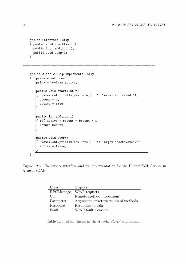
96 12 WEB SERVICES AND SOAP
public interface IBlip
{ public void start(int n);
public int add(int i);
public void stop();
}
==========================================================================
public class WSBlip implements IBlip
{ private int bcount;
private boolean active;
public void start(int n)
{ System.out.println(new Date() + ": Target activated.");
bcount = n;
active = true;
}
public int add(int i)
{ if( active ) bcount = bcount + i;
return bcount;
}
public void stop()
{ System.out.println(new Date() + ": Target deactivated.");
active = false;
}
}
Figure 12.5: The service interface and its implementation for the Blipper Web Service inApache SOAP
Class ObjectsRPCMessage SOAP requests.Call Remote method invocations.Parameter Arguments or return values of methods.Response Responses to calls.Fault SOAP fault elements.
Table 12.3: Main classes in the Apache SOAP environment
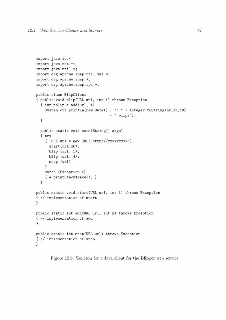
12.4 Web Service Clients and Servers 97
import java.io.*;
import java.net.*;
import java.util.*;
import org.apache.soap.util.xml.*;
import org.apache.soap.*;
import org.apache.soap.rpc.*;
public class BlipClient
{ public void blip(URL url, int i) throws Exception
{ int nblip = add(url, i)
System.out.println(new Date() + ": " + Integer.toString(nblip,10)
+ " blips");
}
public static void main(String[] args)
{ try
{ URL url = new URL("http://xxxxxxxxx");
start(url,20);
blip (url, 1);
blip (url, 4);
stop (url);
}
catch (Exception e)
{ e.printStackTrace(); }
}
public static void start(URL url, int i) throws Exception
{ // implementation of start
}
public static int add(URL url, int n) throws Exception
{ // implementation of add
}
public static int stop(URL url) throws Exception
{ // implementation of stop
}
Figure 12.6: Skeleton for a Java client for the Blipper web service
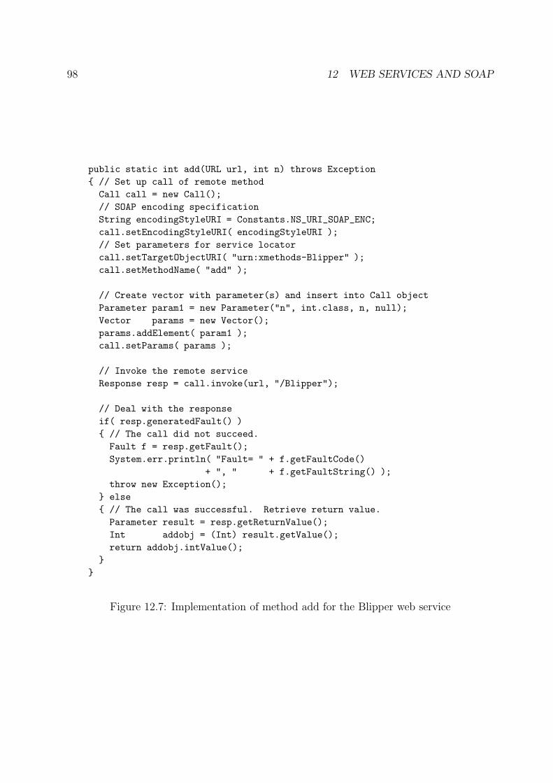
98 12 WEB SERVICES AND SOAP
public static int add(URL url, int n) throws Exception
{ // Set up call of remote method
Call call = new Call();
// SOAP encoding specification
String encodingStyleURI = Constants.NS_URI_SOAP_ENC;
call.setEncodingStyleURI( encodingStyleURI );
// Set parameters for service locator
call.setTargetObjectURI( "urn:xmethods-Blipper" );
call.setMethodName( "add" );
// Create vector with parameter(s) and insert into Call object
Parameter param1 = new Parameter("n", int.class, n, null);
Vector params = new Vector();
params.addElement( param1 );
call.setParams( params );
// Invoke the remote service
Response resp = call.invoke(url, "/Blipper");
// Deal with the response
if( resp.generatedFault() )
{ // The call did not succeed.
Fault f = resp.getFault();
System.err.println( "Fault= " + f.getFaultCode()
+ ", " + f.getFaultString() );
throw new Exception();
} else
{ // The call was successful. Retrieve return value.
Parameter result = resp.getReturnValue();
Int addobj = (Int) result.getValue();
return addobj.intValue();
}
}
Figure 12.7: Implementation of method add for the Blipper web service
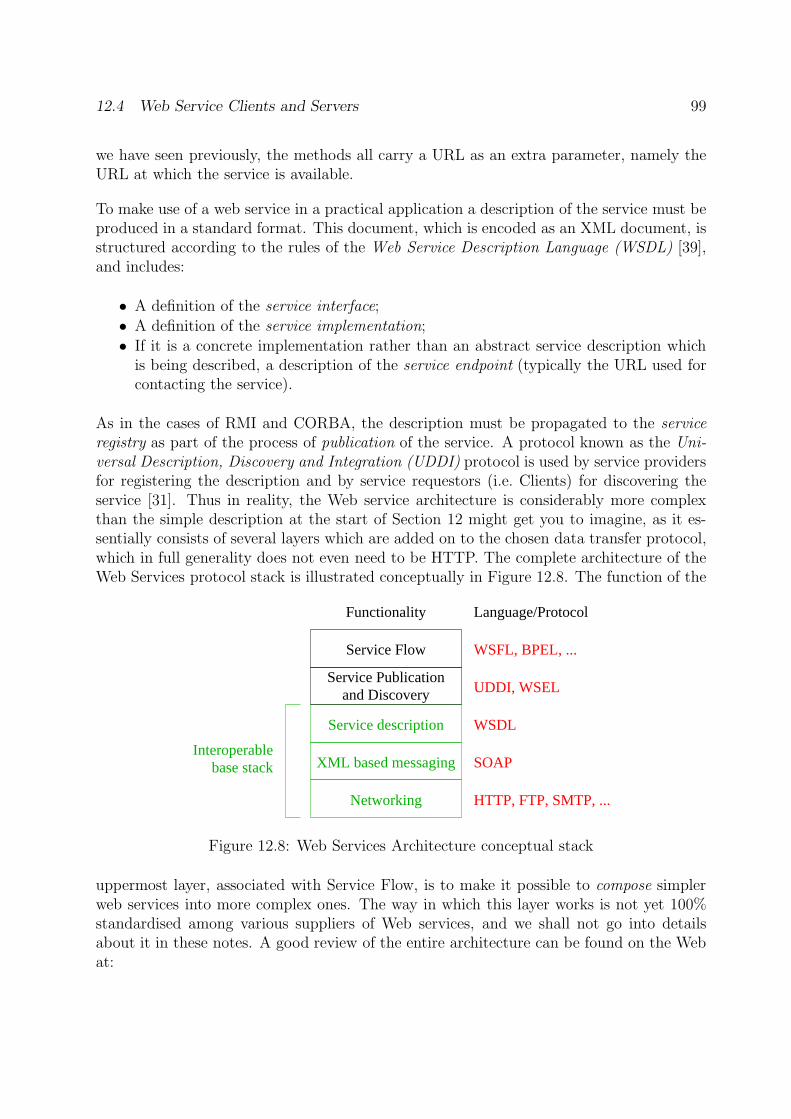
12.4 Web Service Clients and Servers 99
we have seen previously, the methods all carry a URL as an extra parameter, namely theURL at which the service is available.
To make use of a web service in a practical application a description of the service must beproduced in a standard format. This document, which is encoded as an XML document, isstructured according to the rules of the Web Service Description Language (WSDL) [39],and includes:
• A definition of the service interface;
• A definition of the service implementation;
• If it is a concrete implementation rather than an abstract service description whichis being described, a description of the service endpoint (typically the URL used forcontacting the service).
As in the cases of RMI and CORBA, the description must be propagated to the serviceregistry as part of the process of publication of the service. A protocol known as the Uni-versal Description, Discovery and Integration (UDDI) protocol is used by service providersfor registering the description and by service requestors (i.e. Clients) for discovering theservice [31]. Thus in reality, the Web service architecture is considerably more complexthan the simple description at the start of Section 12 might get you to imagine, as it es-sentially consists of several layers which are added on to the chosen data transfer protocol,which in full generality does not even need to be HTTP. The complete architecture of theWeb Services protocol stack is illustrated conceptually in Figure 12.8. The function of the
UDDI, WSEL
Service Flow
Service Publicationand Discovery
WSDL
SOAP
HTTP, FTP, SMTP, ...
Language/ProtocolFunctionality
Interoperablebase stack
Service description
XML based messaging
Networking
WSFL, BPEL, ...
Figure 12.8: Web Services Architecture conceptual stack
uppermost layer, associated with Service Flow, is to make it possible to compose simplerweb services into more complex ones. The way in which this layer works is not yet 100%standardised among various suppliers of Web services, and we shall not go into detailsabout it in these notes. A good review of the entire architecture can be found on the Webat:
100 13 FURTHER READING
http://www.sigmod.org/sigmod/record/issues/0506/p86-column-libkin.pdf
while organisations such as SoapWare, which acts as a forum for SOAP developers, haveproduced a number of more specialised tutorials on the use of SOAP, which can be foundon SoapWare’s website at www.soapware.org.
13 Further Reading
There are many books and other sources for more information about the topics of thesenotes. For a gentle, but more detailed, introduction to Internet protocols, Comer’s “Com-puter Networks and Internets” [3] is an excellent starting point. More information aboutcomputer networks in general can be found in the books by Tanenbaum [36], Halsall [6] andStallings [34], while local area networks are treated in detail in [35]. Of course, these bookscover a lot of ground, and run to several hundred pages, so they are not really suitable asintroductory material.
For full details of Internet protocols, you need to refer to the Internet Requests for Com-ments (RFC’s), of which several important ones are listed in the Bibliography. These canall be obtained from the Internet itself via the Web page:
http://www.rfc-editor.org/rfcsearch.html
from where you can search for and retrieve RFCs by number or keyword. It is not possibleto see directly from an RFC which status it has, i.e. whether it describes an acceptedstandard, a proposed standard or just a draft for comment. To find this out, you needto look at the latest version of the list of Internet standards; this list is itself an RFC,currently RFC3300. Standards from the International Telecommunications Union (ITU-T), the International Organization for Standardization (ISO) and IEEE can be purchasedfrom these organisations.
These notes have focussed on how to construct distributed applications based on the sim-plest form of client-server model, with one or more clients and a single server. While thisis an important and very much used model, it is by no means the only one. Many inter-esting systems use multi-tier models, where a server can itself be a client for one or moreother servers. A simple example of this is shown in Figure 13.1, which shows a three-tierarchitecture, involving presentation, an actual application and data storage.
A further development of this is to use hierarchical architectures, in which participatingprocesses are organised in a tree-like structure, and where information passes up and downthe branches of the tree. Other systems make use of a set of cooperating agents. Agents may
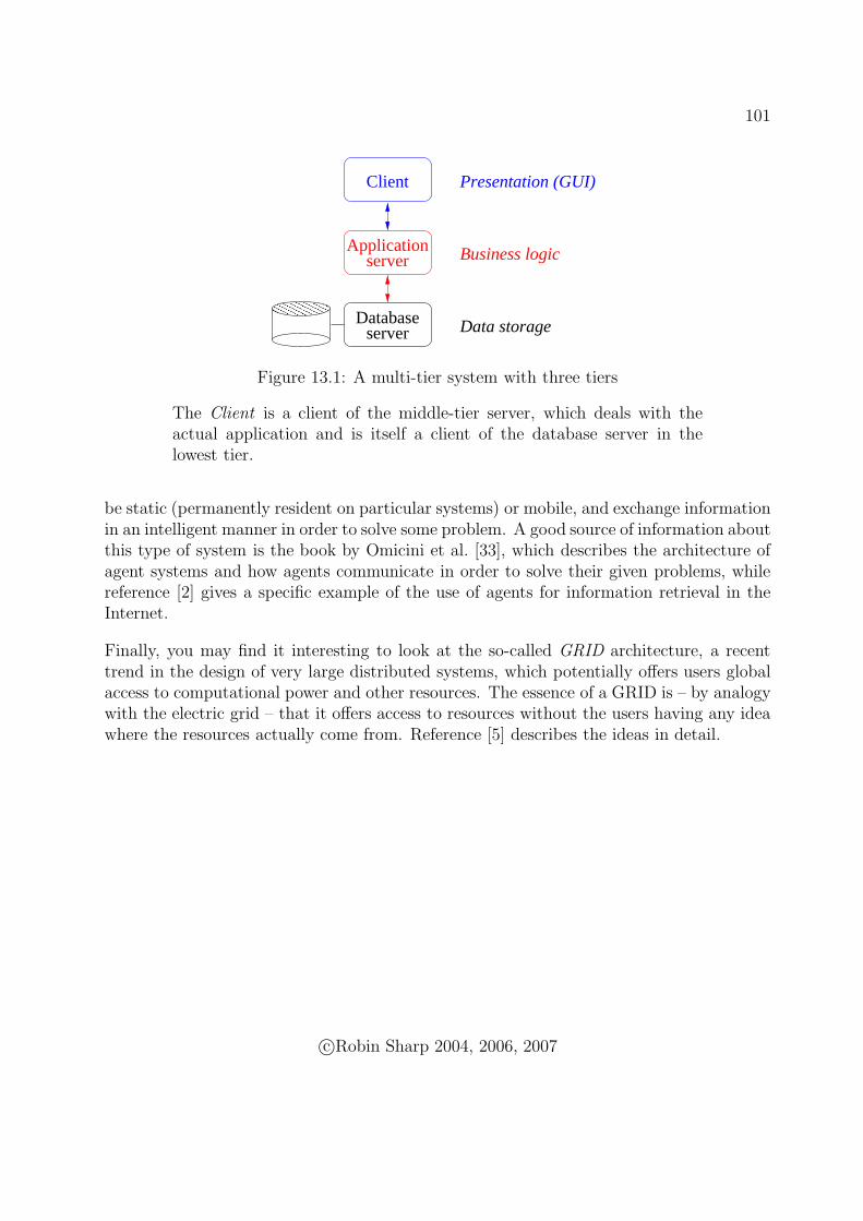
101
��������������������
Client
Applicationserver
Databaseserver
Business logic
Data storage
Presentation (GUI)
Figure 13.1: A multi-tier system with three tiers
The Client is a client of the middle-tier server, which deals with theactual application and is itself a client of the database server in thelowest tier.
be static (permanently resident on particular systems) or mobile, and exchange informationin an intelligent manner in order to solve some problem. A good source of information aboutthis type of system is the book by Omicini et al. [33], which describes the architecture ofagent systems and how agents communicate in order to solve their given problems, whilereference [2] gives a specific example of the use of agents for information retrieval in theInternet.
Finally, you may find it interesting to look at the so-called GRID architecture, a recenttrend in the design of very large distributed systems, which potentially offers users globalaccess to computational power and other resources. The essence of a GRID is – by analogywith the electric grid – that it offers access to resources without the users having any ideawhere the resources actually come from. Reference [5] describes the ideas in detail.
c©Robin Sharp 2004, 2006, 2007

102 13 FURTHER READING
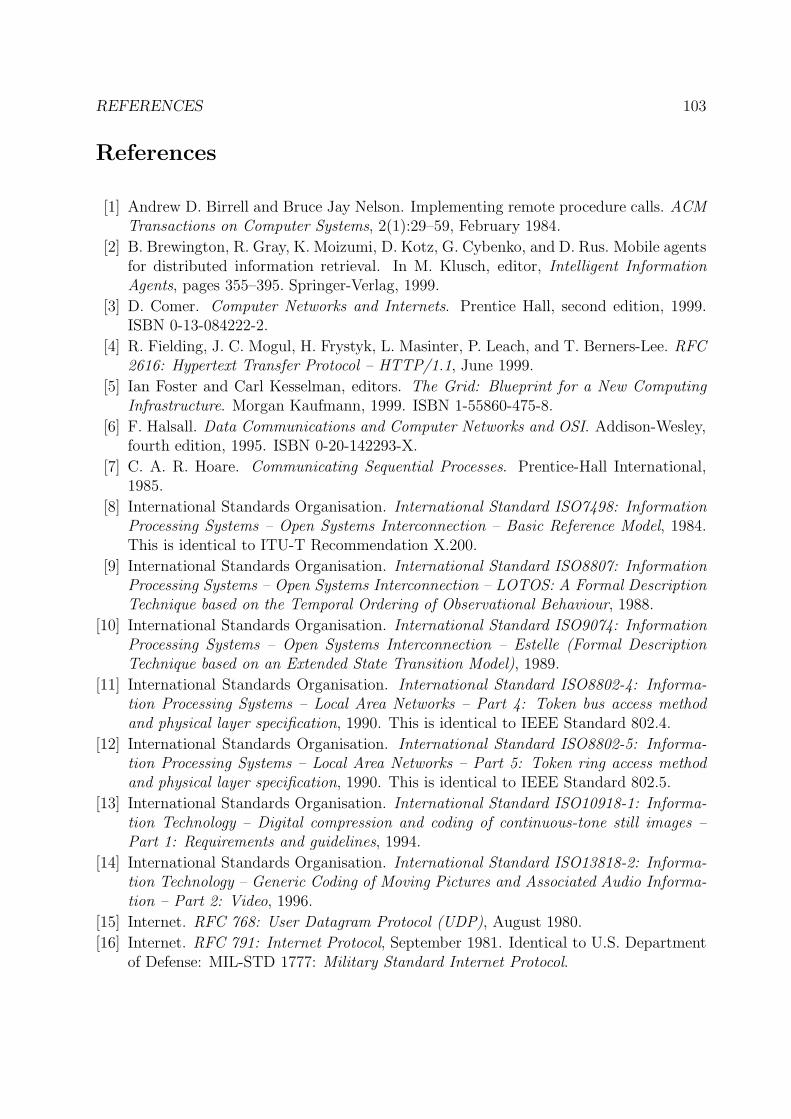
REFERENCES 103
References
[1] Andrew D. Birrell and Bruce Jay Nelson. Implementing remote procedure calls. ACMTransactions on Computer Systems, 2(1):29–59, February 1984.
[2] B. Brewington, R. Gray, K. Moizumi, D. Kotz, G. Cybenko, and D. Rus. Mobile agentsfor distributed information retrieval. In M. Klusch, editor, Intelligent InformationAgents, pages 355–395. Springer-Verlag, 1999.
[3] D. Comer. Computer Networks and Internets. Prentice Hall, second edition, 1999.ISBN 0-13-084222-2.
[4] R. Fielding, J. C. Mogul, H. Frystyk, L. Masinter, P. Leach, and T. Berners-Lee. RFC2616: Hypertext Transfer Protocol – HTTP/1.1, June 1999.
[5] Ian Foster and Carl Kesselman, editors. The Grid: Blueprint for a New ComputingInfrastructure. Morgan Kaufmann, 1999. ISBN 1-55860-475-8.
[6] F. Halsall. Data Communications and Computer Networks and OSI. Addison-Wesley,fourth edition, 1995. ISBN 0-20-142293-X.
[7] C. A. R. Hoare. Communicating Sequential Processes. Prentice-Hall International,1985.
[8] International Standards Organisation. International Standard ISO7498: InformationProcessing Systems – Open Systems Interconnection – Basic Reference Model, 1984.This is identical to ITU-T Recommendation X.200.
[9] International Standards Organisation. International Standard ISO8807: InformationProcessing Systems – Open Systems Interconnection – LOTOS: A Formal DescriptionTechnique based on the Temporal Ordering of Observational Behaviour, 1988.
[10] International Standards Organisation. International Standard ISO9074: InformationProcessing Systems – Open Systems Interconnection – Estelle (Formal DescriptionTechnique based on an Extended State Transition Model), 1989.
[11] International Standards Organisation. International Standard ISO8802-4: Informa-tion Processing Systems – Local Area Networks – Part 4: Token bus access methodand physical layer specification, 1990. This is identical to IEEE Standard 802.4.
[12] International Standards Organisation. International Standard ISO8802-5: Informa-tion Processing Systems – Local Area Networks – Part 5: Token ring access methodand physical layer specification, 1990. This is identical to IEEE Standard 802.5.
[13] International Standards Organisation. International Standard ISO10918-1: Informa-tion Technology – Digital compression and coding of continuous-tone still images –Part 1: Requirements and guidelines, 1994.
[14] International Standards Organisation. International Standard ISO13818-2: Informa-tion Technology – Generic Coding of Moving Pictures and Associated Audio Informa-tion – Part 2: Video, 1996.
[15] Internet. RFC 768: User Datagram Protocol (UDP), August 1980.
[16] Internet. RFC 791: Internet Protocol, September 1981. Identical to U.S. Departmentof Defense: MIL-STD 1777: Military Standard Internet Protocol.
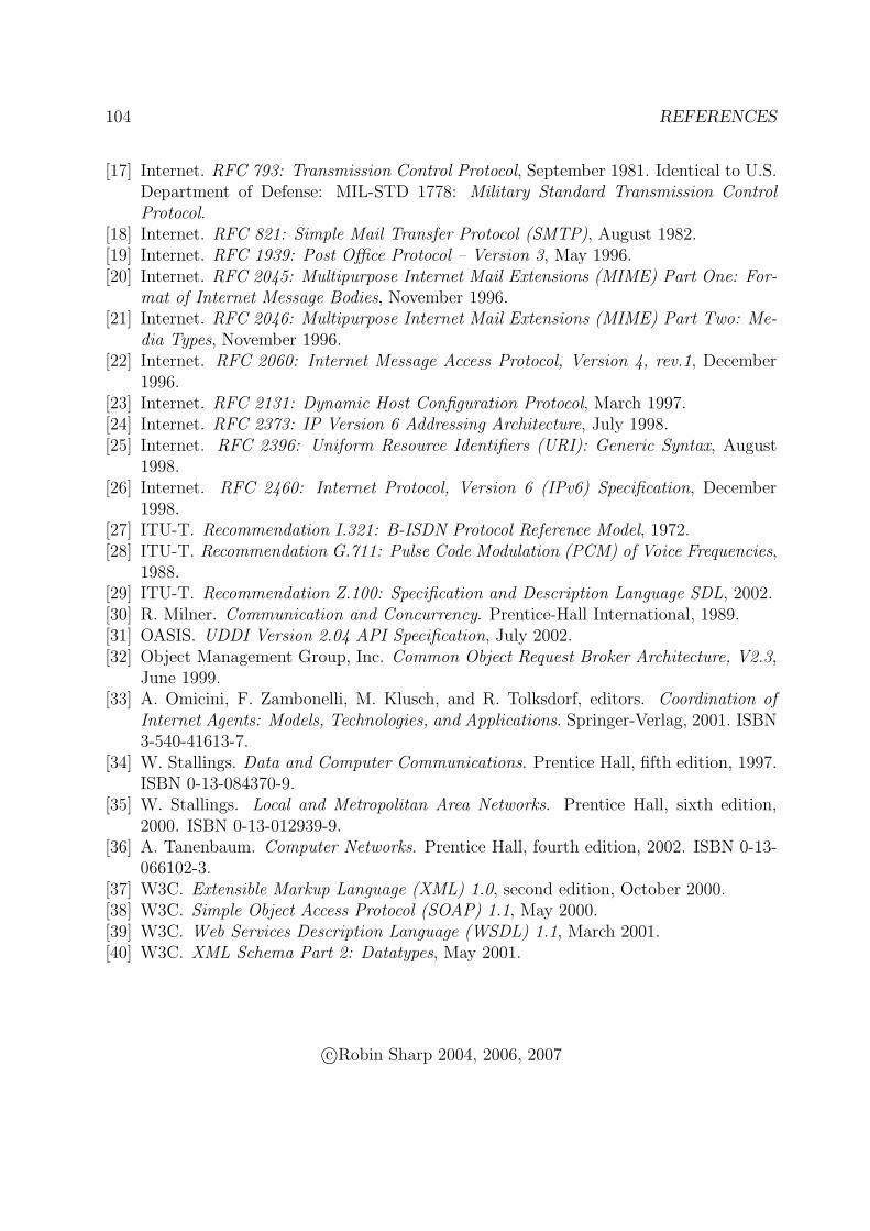
104 REFERENCES
[17] Internet. RFC 793: Transmission Control Protocol, September 1981. Identical to U.S.Department of Defense: MIL-STD 1778: Military Standard Transmission ControlProtocol.
[18] Internet. RFC 821: Simple Mail Transfer Protocol (SMTP), August 1982.[19] Internet. RFC 1939: Post Office Protocol – Version 3, May 1996.[20] Internet. RFC 2045: Multipurpose Internet Mail Extensions (MIME) Part One: For-
mat of Internet Message Bodies, November 1996.[21] Internet. RFC 2046: Multipurpose Internet Mail Extensions (MIME) Part Two: Me-
dia Types, November 1996.[22] Internet. RFC 2060: Internet Message Access Protocol, Version 4, rev.1, December
1996.[23] Internet. RFC 2131: Dynamic Host Configuration Protocol, March 1997.[24] Internet. RFC 2373: IP Version 6 Addressing Architecture, July 1998.[25] Internet. RFC 2396: Uniform Resource Identifiers (URI): Generic Syntax, August
1998.[26] Internet. RFC 2460: Internet Protocol, Version 6 (IPv6) Specification, December
1998.[27] ITU-T. Recommendation I.321: B-ISDN Protocol Reference Model, 1972.[28] ITU-T. Recommendation G.711: Pulse Code Modulation (PCM) of Voice Frequencies,
1988.[29] ITU-T. Recommendation Z.100: Specification and Description Language SDL, 2002.[30] R. Milner. Communication and Concurrency. Prentice-Hall International, 1989.[31] OASIS. UDDI Version 2.04 API Specification, July 2002.[32] Object Management Group, Inc. Common Object Request Broker Architecture, V2.3,
June 1999.[33] A. Omicini, F. Zambonelli, M. Klusch, and R. Tolksdorf, editors. Coordination of
Internet Agents: Models, Technologies, and Applications. Springer-Verlag, 2001. ISBN3-540-41613-7.
[34] W. Stallings. Data and Computer Communications. Prentice Hall, fifth edition, 1997.ISBN 0-13-084370-9.
[35] W. Stallings. Local and Metropolitan Area Networks. Prentice Hall, sixth edition,2000. ISBN 0-13-012939-9.
[36] A. Tanenbaum. Computer Networks. Prentice Hall, fourth edition, 2002. ISBN 0-13-066102-3.
[37] W3C. Extensible Markup Language (XML) 1.0, second edition, October 2000.[38] W3C. Simple Object Access Protocol (SOAP) 1.1, May 2000.[39] W3C. Web Services Description Language (WSDL) 1.1, March 2001.[40] W3C. XML Schema Part 2: Datatypes, May 2001.
c©Robin Sharp 2004, 2006, 2007
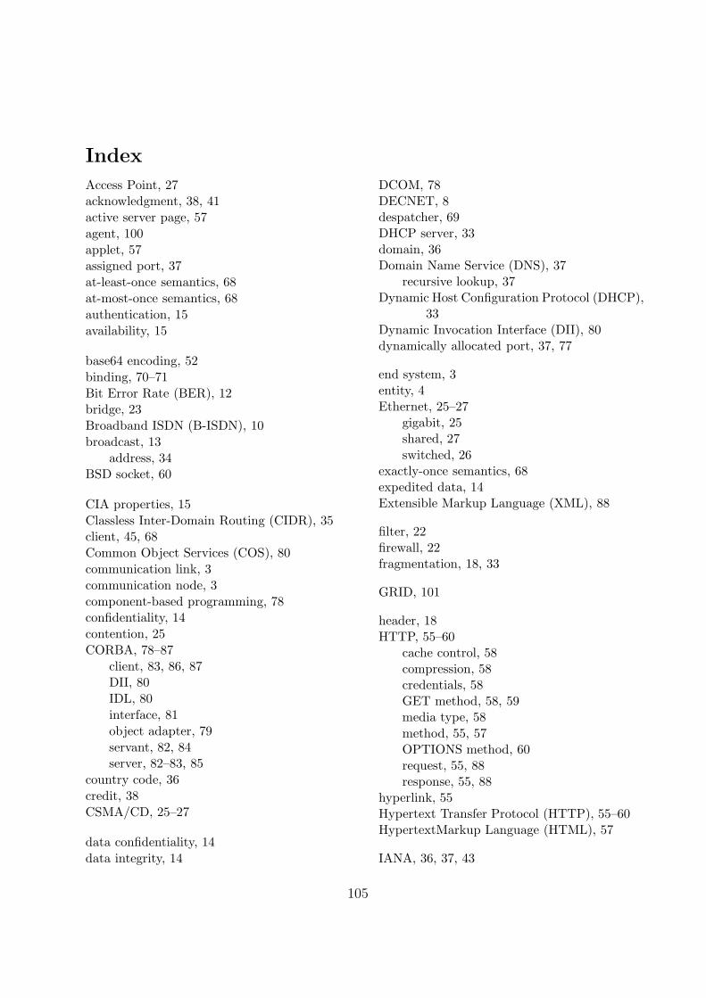
Index
Access Point, 27acknowledgment, 38, 41
active server page, 57
agent, 100
applet, 57assigned port, 37
at-least-once semantics, 68
at-most-once semantics, 68
authentication, 15
availability, 15
base64 encoding, 52
binding, 70–71
Bit Error Rate (BER), 12bridge, 23
Broadband ISDN (B-ISDN), 10
broadcast, 13
address, 34BSD socket, 60
CIA properties, 15
Classless Inter-Domain Routing (CIDR), 35client, 45, 68
Common Object Services (COS), 80
communication link, 3
communication node, 3
component-based programming, 78confidentiality, 14
contention, 25
CORBA, 78–87
client, 83, 86, 87DII, 80
IDL, 80
interface, 81
object adapter, 79
servant, 82, 84server, 82–83, 85
country code, 36
credit, 38
CSMA/CD, 25–27
data confidentiality, 14
data integrity, 14
DCOM, 78DECNET, 8despatcher, 69DHCP server, 33domain, 36Domain Name Service (DNS), 37
recursive lookup, 37Dynamic Host Configuration Protocol (DHCP),
33Dynamic Invocation Interface (DII), 80dynamically allocated port, 37, 77
end system, 3entity, 4Ethernet, 25–27
gigabit, 25shared, 27
switched, 26exactly-once semantics, 68expedited data, 14Extensible Markup Language (XML), 88
filter, 22
firewall, 22fragmentation, 18, 33
GRID, 101
header, 18HTTP, 55–60
cache control, 58compression, 58credentials, 58GET method, 58, 59media type, 58
method, 55, 57OPTIONS method, 60request, 55, 88response, 55, 88
hyperlink, 55Hypertext Transfer Protocol (HTTP), 55–60HypertextMarkup Language (HTML), 57
IANA, 36, 37, 43
105
106 INDEX
implementation repository, 79inheritance model, 82
integrity, 14
interface, 80, 81Interface Definition Language (IDL), 69, 71,
80
interface repository, 79
International Organization for Standardisa-tion (ISO), 21
International Telecommunications Union (ITU-T), 21
Internet, 8protocol, 8
Internet Application Layer, 43
Internet Message Access Protocol (IMAP),44
Internet Protocol (IP), 30–37
IPv4, 30IPv6, 30
ISO, 21
ITU-T, 21
Javacodebase, 77
IDL, 81
remote exception, 73remote interface, 71, 73
remote object, 71, 74
RMI, 71–78security manager, 75
security policy, 77
jitter, 16
LAN, 14
layer, 4
layered architecture, 4–10link, 55, 57
Local Area Network (LAN), 3, 14
Logical Link Control (LLC), 24
mailbox, 44mailer, 44
marshalling, 69
Maximum Segment Lifetime (MSL), 42maybe semantics, 68
MD5, 60
Medium Access Control (MAC), 24method
accept, 66
HTTP, 55, 57Metropolitan Area Network (MAN), 3
MIME, 49–53body, 49
composite type, 49, 50
discrete type, 49, 50entity, 49
header, 49
subtype, 49, 50type, 49, 50, 58
multi-tier model, 100multicast, 13
multicast group, 13, 34
multiplexing, 13
(N)-entity, 4
(N)-protocol, 4Nagle’s algorithm, 42
name, 35naming authority, 36
naming domain, 36
.NET, 95netmask, 34
network class, 34
node, 3communication, 3
non-repudiation, 15
object, 68
object adapter, 79Object Management Group (OMG), 78
Object Request Broker (ORB), 78
Open Systems Interconnection (OSI), 4OSI Reference Model, 4–8
packing, 18path, 54
PDU format, 20piggybacking, 41
port, 37, 43, 54
assigned, 37dynamically allocated, 37, 77
registered, 37
INDEX 107
portable implementation, 79Portable Object Adapter (POA), 80, 82
Post Office Protocol (POP), 44
Private Network (PN), 34protocol, 4, 10
Protocol Control Information (PCI), 17–20Protocol Data Unit (PDU), 17
proxy
object, 70
Quality of Service (QoS), 15–16
query, 54
reassembly, 18
receive window, 38registered port, 37
registry, 70, 73, 75, 95, 99
remote interface, 71, 73Remote Method Invocation (RMI), 71–78
remote object, 70, 71, 75Remote Object Invocation (ROI), 70–78
Remote Procedure Call (RPC), 67–69
Residual Error Rate (RER), 12resource, 54
retransmission, 41RFC, 100
RMI-IIOP, 87
ROI, 70–78round-trip time (RTT), 41
router, 22
RPC, 67–69call semantics, 68
idempotent, 68marshalling, 69
stub, 68
Rules of procedure, 20
scheme, 54
secure service, 14security, 14–15
security manager, 75security policy, 77
segmentation, 18, 33
sequence number, 38sequence preservation, 14
serialise, 71
servant, 82
server, 45, 68, 82
server script, 57
service, 4, 10–16
authenticated, 15
block oriented, 11
broadcast, 13
confidential, 14
connection-mode, 12
connectionless-mode, 12
duplex, 13, 39
integrity of, 14
inverse broadcast, 13
message oriented, 11
multi-peer, 13
multicast, 13
multiplex, 13
non-repudiating, 15
peer-to-peer, 13
secure, 14
sequence preserving, 10
simplex, 13
stream oriented, 11
two-peer, 13
Service Data Unit (SDU), 18
Simple Mail Transfer Protocol (SMTP), 44–52
Simple Object Access Protocol (SOAP), 87–100
skeleton, 79
SMTP
command, 45–46
extensions, 49
reply, 45, 48
SNA, 8
SOAP, 87–100
Apache, 95
body, 88, 91
body entry, 88
compound type, 93
envelope, 88
faultcode, 93
header, 88
header entry, 88
message, 88
108 INDEX
request, 88response, 88, 91–93
simple type, 93type, 93–95
socket, 60
BSD, 60Java client, 61–62Java server, 66–67
software component, 78stream, 11
stream filter, 62stub, 68, 71, 79Sun RPC, 69
switch, 26
TCP, 37–43acknowledgment, 38, 41
credit, 38flags, 41padding, 39
reset, 43retransmission, 41round-trip time (RTT), 41
sequence number, 38window, 38
thread, 67, 69
three-way handshake, 39time-to-live, 33
timeout, 66token bus, 14token ring, 14
trader, 70trailer, 18Transmission Control Protocol (TCP), 37–43
typeserialisable, 71
Uniform Resource Identifier (URI), 54–55
Universal Description, Discovery and Inte-gration (UDDI), 99
urgent data, 14URI, 54–55, 71, 73
path, 54port, 54query, 54
scheme, 54
User Datagram Protocol (UDP), 43
Web resource, 54Web service, 88, 99–100
publication, 95, 99registry, 95, 99
Web Service Description Language (WSDL),99
Wide Area Network (WAN), 3window, 38window protocol, 38Wireless LAN, 27–29World Wide Web, 52–60
XML, 88–95array, 94datatype, 93–95declaration, 89derived type, 95document, 88element, 88, 89enumeration type, 93namespace, 91struct, 93ur-type, 95


![The Poor Man's Porter (Synopsis of chs. 1-5 of *Verbal ...ntresources.com/documents/porter.pdf · “The Poor Man’s Porter ... tagmemic grammar [Pike], or word grammar ... expression](https://img.pdfslide.net/doc/110x75/5b3e68507f8b9ac34d8b49bb/the-poor-mans-porter-synopsis-of-chs-1-5-of-verbal-the-poor-mans.jpg)