Embed Size (px)
Citation preview

© Copyright September 2019, Presby Environmental, Inc., All Rights Reserved.
The Presby Wastewater
Treatment System
Enviro-Septic®
Design and Installation Manual
Minimizes the Expense Protects the Environment Preserves the Site
Presby Environmental, Inc.
An Infiltrator Water Technologies Company The Next Generation of Wastewater Treatment Technology
143 Airport Rd., Whitefield, NH 03598 Tel: 800-473-5298 Fax: 603-837-9864
[email protected] www.PresbyEnvironmental.com
The information in this manual is subject to change without notice. We recommend that you check your state’s page on our website on a regular basis for updated information. Your suggestions and comments are welcome. Please contact us at:
Presby Environmental, Inc. 143 Airport Road
Whitefield, NH 03598 Phone: 1-800-473-5298 Fax: (603) 837-9864
Website: www.presbyenvironmental.com
The products and methods depicted in this manual are protected by one or more patents. For more information:
Pat. www.presbyeco.com/patents.
Enviro-Septic® is a registered trademark of Presby Environmental Inc.
IMPORTANT NOTICE: This Manual is intended ONLY for use in designing and installing Presby Environmental’s Enviro-Septic® Wastewater Treatment Systems. The use of this Manual with any other product is prohibited. The processes and design criteria contained herein are based solely on our experience with and testing of Enviro-Septic®. Substitution of any other large diameter gravelless pipe will result in compromised treatment of wastewater and other adverse effects.
This manual refers to the Certification for General Use (Transmittal Number X233394) and the Certification for Remedial Use (Transmittal Number X233395) for use under Title 5 Innovative / Alternative Technology Approval
issued by the State of Massachusetts Department of Environmental Protection.
All designers must provide the above approval letter to each landowner who is a prospective purchaser of a System prior to the sale of the system and prior to the filing of any application for a site-specific approval.
To access the approval letters and the Standard Conditions for Alternative SAS Systems, please go to
Massachusetts Department of Environmental Protection web page at: https://www.mass.gov/guides/approved-title-5-innovativealternative-technologies.
© 2010-2019 Presby Environmental, Inc.
All rights reserved
© Presby Environmental, Inc., Massachusetts Enviro-Septic® D&I Manual, September 2019 Edition -1-
Enviro-Septic® Wastewater Treatment System Massachusetts Design and Installation Manual
Preview
Background Liquid that exits from a septic tank (effluent) contains suspended solids that cause other types
of leaching systems to fail. Solids overload bacteria, cut off aeration required for bacterial activity, and seal the underlying soil.
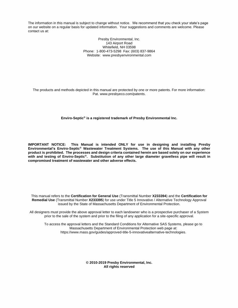
System components
Here’s a picture of the Enviro-Septic® system components.
What our system does
By utilizing simple, yet effective natural processes, the Enviro-Septic® wastewater treatment system treats septic tank effluent in a manner that prevents solids from entering surrounding soils, increases system aeration, and provides a greater bacterial area (biomat) than traditional systems.
Why our system excels
The Enviro-Septic® wastewater treatment system retains solids in its pipe and provides multiple bacterial surfaces to treat effluent prior to its contact with the soil. The continual cycling of effluent (the rising and falling of liquid inside the pipe) enhances bacterial growth. No other design offers this functionality. Our systems excel because they are more efficient, last longer, and have a minimal environmental impact.
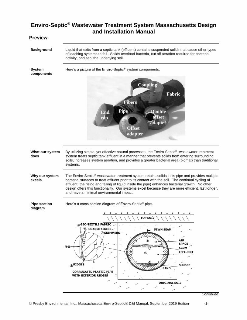
Pipe section diagram
Here’s a cross section diagram of Enviro-Septic® pipe.
Continued
ORIGINAL SOIL
CORRUGATED PLASTIC PIPE WITH EXTERIOR RIDGES
4 RIDGES 2 SAND
2 1
COARSE FIBERS GEO-TEXTILE FABRIC
SKIMMERS 5
3
6 SEWN SEAM
TOP SOIL
SCUM EFFLUENT
SLUDGE
AIR SPACE
9
8 7
Offset
adapter
End
cap
Pipe
Fibers
Coupling
Fabric
Double
offset
adapter
© Presby Environmental, Inc., Massachusetts Enviro-Septic® D&I Manual, September 2019 Edition -2-
Preview Continued
How it works These are the nine stages in the Enviro-Septic® Wastewater Treatment System.
Stage What Happens
1 Warm effluent enters the pipe and is cooled to ground temperature.
2 Suspended solids separate from the cooled liquid effluent.
3 Skimmers further capture grease and suspended solids from the effluent as it exits through perforations in the pipe.
4 Pipe ridges allow the effluent to flow uninterrupted around the circumference of the pipe and aid in cooling.
5 A mat of random, coarse fibers separates more suspended solids from the effluent.
6 Effluent passes into the geo-textile fabric and grows a protected bacterial surface.
7 Sand wicks the liquid from the geo-textile fabric and enables air to transfer to the bacterial surface.
8 Fabric and fibers provide a large bacterial surface to break down solids.
9 An ample air supply and fluctuating liquid levels increase bacterial efficiency.
System advantages
An Enviro-Septic® (ES) wastewater treatment system
• costs less than traditional installation products and materials
• requires a smaller area
• blends into sloping terrain
• adapts to difficult sites
• installs more easily and quickly than traditional systems
• eliminates the need for expensive washed stone
• adapts easily to both commercial and residential sites
• uses a protected receiving surface
• increases system performance and longevity
• tests environmentally safer than conventional systems
• recharges groundwater more safely than conventional systems
In this manual This manual contains the following sections.
Section Page
A – Introduction 3
B – Definitions of Terms 4
C – Design Criteria, Requirements, and Restrictions 7
D – Title 5 and Aggregate Systems Exceptions 11
E – Installation, Handling, and Storage Guidelines 12
F – System Sand Requirements 14
G – Standard System Configurations 15
H – Non-Standard System Configurations 23
I – Pump System Requirements 25
J – Venting Requirements 26
K – Inspection Port Requirements 28
L – Bottom Drains and Requirements 29
M – System Rejuvenation and Expansion 30
N – Quick Reference Guide for Percolation Rates Up to 60 Minutes/Inch 31
O – Quick Reference Guide for Percolation Rates of 61-90 Minutes/Inch 35
System Installation Form Appendix A
Enviro-Septic® Wastewater Treatment System Technology Checklist Appendix B
Enviro-Septic® Wastewater Treatment System Operating Manual Appendix C
© Presby Environmental, Inc., Massachusetts Enviro-Septic® D&I Manual, September 2019 Edition -3-
Section A Introduction
Purpose
The purpose of this manual is to provide guidance in the design and installation of the Presby Environmental, Inc., Enviro-Septic® (ES) wastewater treatment system products.
Presby Environmental, Inc., standards
All systems using Presby Environmental, Inc., ES wastewater treatment system products must be designed and installed in compliance with the procedures and specifications described in this manual.
State standards Title 5, 310 CMR 15.000, the State Environmental Code for Massachusetts covers issues not
addressed in this manual. Title 5 requirements take precedence unless specifically changed by the General Use or Remedial Use approvals issued for the ES system.
Certification required
MassDEP and Presby Environmental, Inc., require all designers and installers to be certified. Certification is obtained by attending the “Enviro-Septic® Designer and Installer Certification Course” presented by Presby Environmental, Inc., or its sanctioned representatives. Until designers and installers are certified, designs and installations must be approved/inspected by Presby Environmental, Inc., or its sanctioned representatives. Special Note: Presby Environmental, Inc., recommends that all individuals involved in the
approval or permitting process also attend these sessions.
“System Installation Form” required
Installers of ES systems shall provide Presby Environmental, Inc., and the local approving authority with a copy of a completed “System Installation Form” for each new or remedial system installed. Reference: See “Appendix A – System Installation Form.”
Technical support Presby Environmental, Inc., provides technical support to all individuals using our products. For
questions about the information contained in this manual, please review our website at www.presbyenvironmental.com or contact us at 1-800-473-5298.
© Presby Environmental, Inc., Massachusetts Enviro-Septic® D&I Manual, September 2019 Edition -4-
Section B Definitions of Terms
Introduction This section defines terms as they are used in this manual.
Basic serial system
A basic serial system is a system consisting of one bed of ES pipe in serial configuration.
Bed A bed is 2 or more lines of ES pipe located within a contiguous inground or raised system sand
bed area.
Bottom drain A bottom drain is a sealed pipe connecting the end of a basic serial system, the ends of all
distribution box system lines, or the end of each section of a combination serial system to a sealed drain.
Center-to-center spacing
Center-to-center spacing is the horizontal distance from the center of one line to the center of the adjacent line.
Combination serial system
A combination serial system is a system incorporating two or more sections of ES pipe in serial configuration, each section receiving effluent from a distribution box.
Coupling A coupling is a fitting that joins two pieces of ES pipe.
D-box D-box is an abbreviation for distribution box.
Design flow Design flow is the assigned peak daily flow of sewage, in gallons per day, from a residence or
commercial facility.
Differential venting
Differential venting is a method of venting an ES system using high and low vents.
Distribution box A distribution box is a device used to divide and/or control effluent flow.
Distribution box manifold
A distribution box manifold is a method of joining any number of distribution box outlets to a single pipe.
Distribution box system
A distribution box system is a number of ES lines of equal length, each supplied evenly with effluent through a distribution box.
Double offset adapter
A double offset adapter is an end cap with a two 4 in. offset holes. Double offset adapters are used in bottom drain installations.
Drain sump A drain sump is a watertight chamber connected to the end of a bottom drain line.
Reference: See Section L, “Bottom Drains and Requirements,” p. 29.
EHGW EHGW is an abbreviation for estimated high ground-water elevations.
End cap An end cap is a cap used at the end of an ES line or section.
Continued
© Presby Environmental, Inc., Massachusetts Enviro-Septic® D&I Manual, September 2019 Edition -5-
Definitions of Terms, Continued
Enviro-Septic® (ES) pipe
An Enviro-Septic® (ES) pipe is a single unit of pipe, 10 ft. in length with an outside diameter of 12 in. and a storage capacity of approximately 58 gallons.
Flow equalizer A flow equalizer is an insert installed in each outlet of a distribution box to equalize the effluent
distribution for multiple outlets.
GPD GPD is an abbreviation for gallons per day.
High and low vents
High and low vents are pipe components used in all systems to ensure that air is drawn completely through the entire ES system.
High flow High flow is a “design daily flow” greater than 500 GPD. High flows require combination or
distribution box system designs or multiple serial beds.
Inground system An inground system is a system installed with the bottom of the system sand bed below the
existing grade.
Level system A level system is a system in which lines of ES are installed at the same elevation.
Line A line is a number of ES pipes connected by couplings with an offset adapter on the inlet
end and an offset adapter on the opposite end.
Low flow Low flow is a “design daily flow” of 500 GPD or less. Basic serial system configuration is
preferred for low flow systems.
Multiple bed System
A multiple bed system incorporates two or more beds, each bed with basic serial or combination serial distribution and receiving effluent from a distribution box.
Offset adapter An offset adapter is an end cap with a 4 in. offset hole. Offset adapters are used for raised
connections, venting and system inlets.
Raised connection
A raised connection is an arrangement of sewer and drain PVC pipe used to connect lines of ES pipe to maintain the correct liquid level inside each line.
Raised system A raised system is a system installed with the bottom of the system sand bed at or above the
existing grade.
Section A section is a group of ES lines in serial distribution receiving effluent from a distribution box in
a combination system.
Serial distribution A serial distribution is a group of ES lines connected with a raised connection.
Reference: See “line”, above.
Slope Slope is the ratio of the difference in elevation and the difference in horizontal distance between
two points on the surface of a landform expressed as a percent, and commonly stated as rise over run. Example: A slope of one percent is the difference in elevation of one foot (rise) over a horizontal distance of one hundred feet (run).
Continued
© Presby Environmental, Inc., Massachusetts Enviro-Septic® D&I Manual, September 2019 Edition -6-
Definitions of Terms, Continued
Sloping system A sloping system is a system in which lines of ES are installed in decreasing elevations.
Smear To smear is to mechanically seal the natural pores of soil along an excavated or tilled surface.
Surrounding sand Surrounding sand is the sand/soil material adjacent to the system sand.
Reference: See specifications, “Section F – System Sand Requirements,” p. 14.
System Sand System sand is the sand immediately surrounding the pipe and is required in all ES
installations. Reference: See specifications, “Section F – System Sand Requirements,” p. 14.
© Presby Environmental, Inc., Massachusetts Enviro-Septic® D&I Manual, September 2019 Edition -7-
Section C Design Criteria, Requirements, and Restrictions
Introduction This section contains a variety of criteria, requirements, and restrictions for designing ES
wastewater treatment systems.
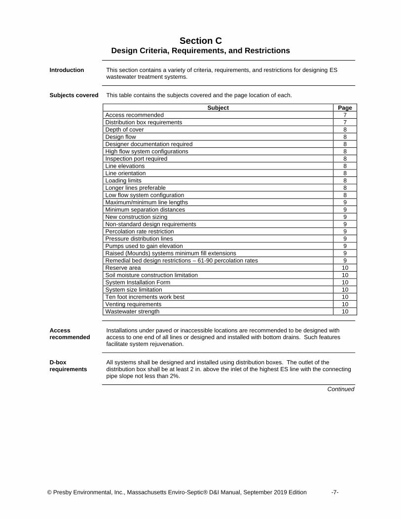
Subjects covered This table contains the subjects covered and the page location of each.
Subject Page
Access recommended 7
Distribution box requirements 7
Depth of cover 8
Design flow 8
Designer documentation required 8
High flow system configurations 8
Inspection port required 8
Line elevations 8
Line orientation 8
Loading limits 8
Longer lines preferable 8
Low flow system configuration 8
Maximum/minimum line lengths 9
Minimum separation distances 9
New construction sizing 9
Non-standard design requirements 9
Percolation rate restriction 9
Pressure distribution lines 9
Pumps used to gain elevation 9
Raised (Mounds) systems minimum fill extensions 9
Remedial bed design restrictions – 61-90 percolation rates 9
Reserve area 10
Soil moisture construction limitation 10
System Installation Form 10
System size limitation 10
Ten foot increments work best 10
Venting requirements 10
Wastewater strength 10
Access recommended
Installations under paved or inaccessible locations are recommended to be designed with access to one end of all lines or designed and installed with bottom drains. Such features facilitate system rejuvenation.
D-box requirements
All systems shall be designed and installed using distribution boxes. The outlet of the distribution box shall be at least 2 in. above the inlet of the highest ES line with the connecting pipe slope not less than 2%.
Continued

© Presby Environmental, Inc., Massachusetts Enviro-Septic® D&I Manual, September 2019 Edition -8-
Design Criteria, Requirements, and Restrictions, Continued
Depth of cover H-10 / H-20 loading requirements
The minimum total depth of cover on Enviro-Septic® lines is 7 inches: 3 in. of system sand plus 4 in. of topsoil. For H-10 and H-20 loading, a minimum of 6 in. of system sand is required over the ES pipes. 12 in. of structural cover over the pipes is designed for H-10 loading and ES pipe with 18 in. of structural cover is designed for H-20 loading* (see illustration below).
*ES pipe with 18 in. of structural cover is designed for H-20 loading by Presby Environmental
Inc. The Mass DEP makes no determination that this design meets the H-20 loading
requirement.
Design flow Design flow is defined in Title 5, 310 CMR 15.002. Design flow criteria are presented in 310
CMR 15.203. When design flow is not established in 310 CMR 15.203, water meter readings
can be used in accordance with 310 CMR 15.203 (6). For residential systems, design flows
below 330 gallons per day require a variance.
Designer documentation required
The designer must provide the system owner with copies of the State’s Certification for General Use and/or Approval for Remedial Use and an “Enviro-Septic® Wastewater Treatment Operating Manual,” and a “Technology Checklist.” Reference: See “Appendix B, Technology Checklist.”
High flow system configurations
High flow is a “design flow” greater than 500 GPD. High flows in soils with perc rates of up to 60 min/inch require combination or distribution box system configurations or multiple serial beds. All high flow systems in soils with perc rates of 61-90 min/inch require multiple serial beds.
Inspection Port required
All systems require an inspection port. Reference: See Section K , Inspection Port Requirements, p. 28.
Line elevations For sloping systems, it is helpful to provide elevations on the design for each line of the system.
Line orientation ES lines must be laid level and should run parallel to contours (perpendicular to sloping terrain).
Loading limits Each basic serial bed, line of a distribution box system, and section of a combination system
has a maximum limit design daily flow of 500 GPD.
Longer lines preferable
All systems should be designed and installed as long and narrow as possible for the site, with the system length perpendicular to the slope of the natural soil, which is usually parallel to the existing site contour.
Low flow system configuration
Low flow is a “design flow” of 500 GPD or less. Basic serial system configuration is preferred for low flow systems.
Continued
AES PIPE
INSTALL STABILIZATION FABRIC WITH A
GRAB TENSILE STRENGTH OF 315 LBS PER
ASTM D 4632" SIX INCHES OVER AES PIPE
EXTEND FABRIC 3' MIN BEYOND
EDGE OF PIPE (ALL EDGES)
BANK RUN GRAVEL
(NO STONES OVER 2"Ø)
PAVEMENT
12" MIN (BELOW PAVEMENT)
6" SYSTEM SAND
VENT MAINIFOLD
NO SAND VOIDS ALLOWED. WALK BETWEEN
ROWS (COMPRESSING SAND) TO ENSURE SAND
FILLS ALL VOIDS AROUND AES PIPES.
BOTTOM DRAINS RECOMMENDED WHEN
AES PIPE ENDS ARE INACCESSIBLE
VE
NT
ST
AC
K
SLOPE
© Presby Environmental, Inc., Massachusetts Enviro-Septic® D&I Manual, September 2019 Edition -9-
Design Criteria, Requirements, and Restrictions, Continued
Maximum / minimum line lengths
No single line of any system may exceed 100 ft. or be less than 30 ft. in length, but the multiple lines of a basic serial system or section of a combination system may total more than 100 ft. in length when connected in series using raised connections.
Reference: See “Section H – Non-Standard System Configurations,” p. 23.
Note: In some instances, site conditions may require lines shorter than 30 ft. or systems longer than 100 ft.. These are non-standard system configurations.
Minimum separation distances
Setback distances are measured from the outer edge of the required system sand. The distances to the estimated high groundwater elevation (EHGW) and other restrictive features are measured from the bottom of the 6 in. of system sand below the bottom of the ES pipe.
Reference: See “Section D – Title 5 and Aggregate Systems Exceptions,” p.11
New construction sizing
For new construction, the system owner initially shall size a soil absorption system in accordance with 310 CMR 15.242 to demonstrate that a conventional Title 5 soil absorption system using aggregate, including a reserve area, can be installed on the site. The system owner may then size the soil absorption system for the ES system.
Non-standard design requirements
Designers shall include on all non-standard system configuration plans, a statement that Presby Environmental, Inc., will not be responsible for systems designed or installed that do not meet the standards established by these procedures and specifications.
Percolation rate restriction
General use systems are limited to sites with a percolation rate of up to 60 min/inch. Remedial systems can be constructed where the percolation rate is up to 90 min/inch.
Pressure distribution lines
The use of pressure distribution lines in ES Wastewater Treatment Systems is prohibited.
Pumps used to gain elevation
Systems incorporating pumps to gain elevation must use differential venting and velocity reduction to control liquid flow. Velocity reduction may be accomplished through the use of a distribution box with a tee or 90° elbow at the force main outlet.
References: See “Section I - Pump System Requirements” p. 25 and “Section J – Venting Requirements,” p. 26.
Special Note: The use of pressure distribution lines in ES Wastewater Treatment Systems is prohibited.
Raised (Mounds) systems minimum fill extensions
All mounded systems shall be designed and constructed in accordance with 310 CMR 15.255. Raised ES systems are designed for sites with soil or depth constraints that do not allow inground configurations. Topsoil is required around the fill perimeter of raised systems.
Reference: See detailed diagrams, p.22.
Note: All mounded systems shall be designed and constructed in accordance with 310 CMR 15.255.
Remedial bed design restrictions – 61-90 percolation rates
Remedial systems in soils with percolation rates greater than 60 and up to 90 minutes per inch must be designed as basic serial systems. A multiple bed system uses a distribution box with flow equalizers. No bed in a multiple bed system can have a design flow of more than 500 GPD. Beds shall be separated by at least six feet of naturally occurring undisturbed soil. To accommodate construction access, additional separation distance may be necessary.
Continued

© Presby Environmental, Inc., Massachusetts Enviro-Septic® D&I Manual, September 2019 Edition -10-
Design Criteria, Requirements, and Restrictions, Continued
Reserve area For new construction a system must contain a reserve area the size of a conventional Title 5
soil absorption system using aggregate. For Remedial systems the system owner must demonstrate that sufficient reserve is not available so that the system can be designed without a reserve area.
Soil moisture construction limitation
If a fragment of soil from about 9 in. below the surface can easily be rolled into a wire, the soil moisture content is too high for construction.
System Installation Form
Installers of ES systems shall provide Presby Environmental, Inc., and the approving authority with a copy of a completed “System Installation Form” for each new or replacement system installed. Reference: See “Appendix A – System Installation Form.”
System size limitation
To meet Massachusetts’ requirements, at no time may an ES system be designed to have a sand bed area less than 60% of a conventional Title 5 aggregate system designed in accordance with 310 CMR 15.252 for the same site. In addition, the minimum area for a system installed for new construction shall be 400 square feet.
Ten foot increments work best
It is easier if line lengths are designed in exact 10 ft. increments since ES pipe is 10 ft. in length. However, if necessary, the pipe is easily cut to meet site constraints.
Venting requirements
Each ES system must be installed with venting at the end of each distribution box line, section, or serial bed. Vent manifolds may be used to connect multiple vents to one vent outlet.
Wastewater strength
Where wastewater strength exceeds typical human sewage waste, additional ES pipe is required. In some cases additional sand bed area will be required to accommodate the additional pipe. Should designers identify high wastewater strength and need assistance, they may consult Presby Environmental, Inc.
© Presby Environmental, Inc., Massachusetts Enviro-Septic® D&I Manual, September 2019 Edition -11-
Section D Title 5 and Aggregate Systems Exceptions
Introduction Due to the unique capabilities of ES systems, some Title 5 and other requirements commonly
associated with aggregate systems do not apply. This page presents some of the more common exceptions.
No septic tank tee filters
Effluent tee filters will not be required for septic tanks used in ES systems.
Serial distribution allowed
Lines of ES pipe may be installed in serial configuration for flows of up to 500 GPD per basic serial bed or combination section.
No pressure distribution
Pressure distribution may not be used with any ES system, including systems that are designed for over 2000 GPD.
Restaurants/ grease traps
ES systems may be used for restaurants and other facilities that use grease traps.
New construction provisions
These are provisions for new construction. Reduced area size ES systems may be installed in an area up to 40% smaller than a conventional Title 5 bed designed in accordance with 310 CMR 15.252. Note: The system sizing tables used in this manual identify minimum ES requirements
reflecting this reduction. Reduction Limitation: Massachusetts limits all systems to a minimum bed size of 400 sq. ft. Minimum vertical separation distances to EHGW In soils with percolation rates of 2 min/in or less the minimum vertical separation distance to the EHGW is 5 ft. measured from the required 6 in. of system sand at the bottom of the ES pipe. In soils with percolation rates greater than 2-60 min/in the minimum vertical separation distance to the EHGW is 4 ft. measured from the required 6 in. of system sand at the bottom of the ES pipe. Minimum naturally occurring pervious soil depth In soils with percolation rates to 60 min/in, the minimum depth of naturally occurring pervious material under a bed is 4 ft., measured from the required 6 in. of system sand at the bottom of the ES pipe.
Remedial use provisions
Minimum vertical separation distances to EHGW For remedial systems in soils with percolation rates of 2 min/in or less, the minimum vertical separation distance to the EHGW, measured from the bottom of the 6 in. of system sand below the ES pipe, may be reduced to 3 ft. if allowed by the local approving authority. In soils with percolation rates greater than 2 to 90 min/in, the minimum vertical separation distance to the EHGW, measured from the bottom of the 6 in. of system sand below the ES pipe, may be reduced to 2 ft. if allowed by the local approving authority. Minimum naturally occurring pervious soil depth In soils with percolation rates to 90 min/in the depth of naturally occurring pervious material under a bed, measured from the bottom of the 6 in. of system sand below the ES pipe, may be reduced to no less than 2 ft. if allowed by the local approving authority.

© Presby Environmental, Inc., Massachusetts Enviro-Septic® D&I Manual, September 2019 Edition -12-
Section E Installation, Handling, and Storage Guidelines
Introduction These guidelines must be observed while installing, handling, and storing ES products.
Site preparation • Remove stumps and organic matter under the required sand bed area of a proposed
system, including the slope extensions of raised systems. Note: In soils with percolation rates of up to 60 minutes per inch also remove the A
Horizon (topsoil).
• Maintain the existing characteristics of the underlying soil as much as possible.
• Add the system sand and/or surrounding sand on the same day that the leach area is excavated.
• Do not allow water to run into or over the system during construction.
• Do not work wet or frozen soils. Do not smear or compact soils while preparing the site. Reference: See “smear,” p. 6. Note: Excavation irregularities shall be filled with system sand or Title 5 fill.
Soil moisture construction limitation
If a fragment of soil from about 9 in below the surface can easily be rolled into a wire, the soil moisture content is too high for construction.
Soil compaction Minimize machine movement to avoid soil compaction and destruction of the soil structure
under and around the system. Be careful not to compact soil on the down slope side of the system.
Level line tolerances
Use a laser level or transit to install lines level. Variations beyond ¼ in. may affect system performance.
Backfilling lines Spread system sand between the lines; carefully walk between the lines to insure system sand
fills all void spaces beneath the ES pipe. Finish spreading system sand to the top of the lines.
Backfilling and final grading
Spread a minimum of 3 in. of system sand over the pipe. Spread the remaining surrounding sand and a minimum of 4 in. of topsoil. Final grading should shed water away from the system. Note: A tracked vehicle may be used to spread the system sand and topsoil as long as it
maintains at least 12 in. of cover over the pipe.
Erosion control Protect the site from erosion by proper grading, mulching, seeding, and control of runoff.
Use raised connections
Raised connections consist of offset adapters, 4 in. PVC sewer and drainpipe, and 90° elbows. Use raised connections to connect lines of ES pipe. They enable greater liquid storage capacity and increase the bacterial surfaces being developed.
Installation Notes: 1. Insert PVC pipe no more than 4 in. into the offset adapter to
prevent air locking. 2. Install the raised connection so that the top of the 90° bend is
level with the top of the offset adapter. 3. Pack sand under and around the raised connection to prevent
movement.
Continued
MAX. 4" 4" PVC Pipe
OFFSET ADAPTER
LEVEL
4" PVC Pipe
OFFSET ADAPTER
90 PVC Bend
90 PVC Bend ENVIRO-SEPTIC PIPE
TOP VIEW SIDE VIEW END VIEW
OFFSET ADAPTER
© Presby Environmental, Inc., Massachusetts Enviro-Septic® D&I Manual, September 2019 Edition -13-
Installation, Handling, and Storage Guidelines, Continued
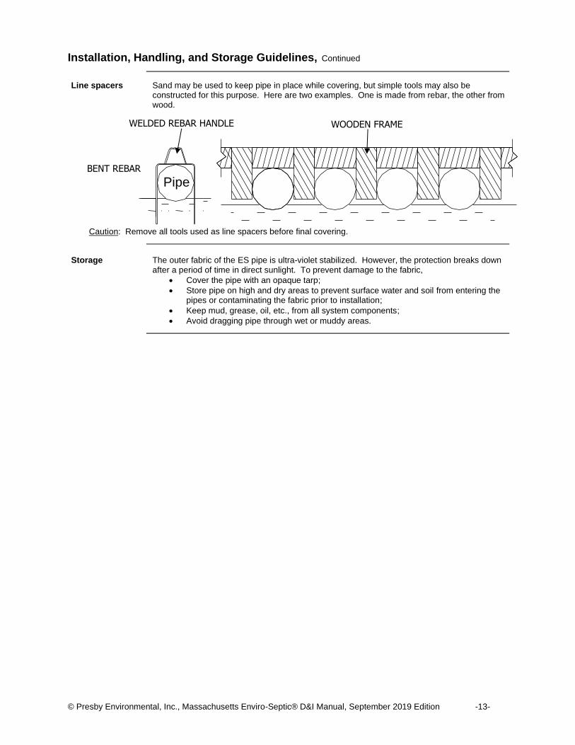
Line spacers Sand may be used to keep pipe in place while covering, but simple tools may also be
constructed for this purpose. Here are two examples. One is made from rebar, the other from wood.
Caution: Remove all tools used as line spacers before final covering.
Storage The outer fabric of the ES pipe is ultra-violet stabilized. However, the protection breaks down
after a period of time in direct sunlight. To prevent damage to the fabric,
• Cover the pipe with an opaque tarp;
• Store pipe on high and dry areas to prevent surface water and soil from entering the pipes or contaminating the fabric prior to installation;
• Keep mud, grease, oil, etc., from all system components;
• Avoid dragging pipe through wet or muddy areas.
BENT REBAR
WELDED REBAR HANDLE WOODEN FRAME
Pipe
© Presby Environmental, Inc., Massachusetts Enviro-Septic® D&I Manual, June 2019 Edition -14-
Section F System Sand Requirements
Introduction This page describes the system sand requirements for the ES wastewater treatment system.
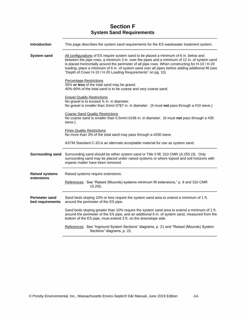
System sand All configurations of ES require system sand to be placed a minimum of 6 in. below and
between the pipe rows, a minimum 3 in. over the pipes and a minimum of 12 in. of system sand is placed horizontally around the perimeter of all pipe rows. When constructing for H-10 / H-20 loading, place a minimum of 6 in. of system sand over all pipes before adding additional fill (see “Depth of Cover H-10 / H-20 Loading Requirements” on pg. 10) Percentage Restrictions 35% or less of the total sand may be gravel. 40%-90% of the total sand is to be coarse and very coarse sand. Gravel Quality Restrictions No gravel is to exceed ¾ in. in diameter. No gravel is smaller than 2mm/.0787 in. in diameter. (It must not pass through a #10 sieve.) Coarse Sand Quality Restrictions No coarse sand is smaller than 0.5mm/.0196 in. in diameter. (It must not pass through a #35 sieve.) Fines Quality Restrictions No more than 3% of the total sand may pass through a #200 sieve. ASTM Standard C-33 is an alternate acceptable material for use as system sand.
Surrounding sand Surrounding sand should be either system sand or Title 5 fill, 310 CMR 15.255 (3). Only
surrounding sand may be placed under raised systems or where topsoil and soil horizons with organic matter have been removed.
Raised systems extensions
Raised systems require extensions. References: See “Raised (Mounds) systems minimum fill extensions,” p. 9 and 310 CMR
15.255.
Perimeter sand bed requirements
Sand beds sloping 10% or less require the system sand area to extend a minimum of 1 ft. around the perimeter of the ES pipe. Sand beds sloping greater than 10% require the system sand area to extend a minimum of 1 ft. around the perimeter of the ES pipe, and an additional 6 in. of system sand, measured from the bottom of the ES pipe, must extend 3 ft. on the downslope side. References: See “Inground System Sections” diagrams, p. 21 and “Raised (Mounds) System
Sections” diagrams, p. 22.
© Presby Environmental, Inc., Massachusetts Enviro-Septic® D&I Manual, September 2019 Edition -15-
Section G Standard System Configurations
Preview
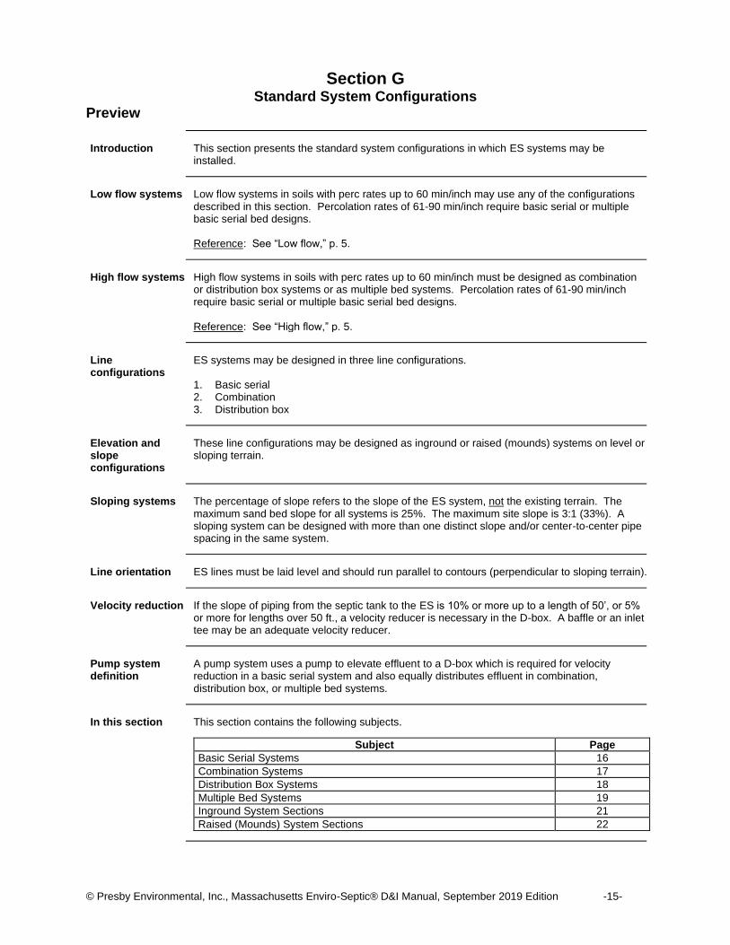
Introduction This section presents the standard system configurations in which ES systems may be
installed.
Low flow systems Low flow systems in soils with perc rates up to 60 min/inch may use any of the configurations
described in this section. Percolation rates of 61-90 min/inch require basic serial or multiple basic serial bed designs. Reference: See “Low flow,” p. 5.
High flow systems High flow systems in soils with perc rates up to 60 min/inch must be designed as combination
or distribution box systems or as multiple bed systems. Percolation rates of 61-90 min/inch require basic serial or multiple basic serial bed designs. Reference: See “High flow,” p. 5.
Line configurations
ES systems may be designed in three line configurations. 1. Basic serial 2. Combination 3. Distribution box
Elevation and slope configurations
These line configurations may be designed as inground or raised (mounds) systems on level or sloping terrain.
Sloping systems The percentage of slope refers to the slope of the ES system, not the existing terrain. The
maximum sand bed slope for all systems is 25%. The maximum site slope is 3:1 (33%). A sloping system can be designed with more than one distinct slope and/or center-to-center pipe spacing in the same system.
Line orientation ES lines must be laid level and should run parallel to contours (perpendicular to sloping terrain).
Velocity reduction If the slope of piping from the septic tank to the ES is 10% or more up to a length of 50’, or 5%
or more for lengths over 50 ft., a velocity reducer is necessary in the D-box. A baffle or an inlet tee may be an adequate velocity reducer.
Pump system definition
A pump system uses a pump to elevate effluent to a D-box which is required for velocity reduction in a basic serial system and also equally distributes effluent in combination, distribution box, or multiple bed systems.
In this section This section contains the following subjects.
Subject Page
Basic Serial Systems 16
Combination Systems 17
Distribution Box Systems 18
Multiple Bed Systems 19
Inground System Sections 21
Raised (Mounds) System Sections 22
© Presby Environmental, Inc., Massachusetts Enviro-Septic® D&I Manual, September 2019 Edition -16-
Basic Serial Systems
Introduction Basic serial distribution is preferred for single beds of 500 GPD or less and multiple bed
systems where each bed receives 500 GPD or less. Basic serial distribution is quick to develop a strong biomat in the first line, providing improved effluent treatment. Basic serial distribution provides a longer flow route to allow decomposition of solids and greases, providing improved long term treatment.
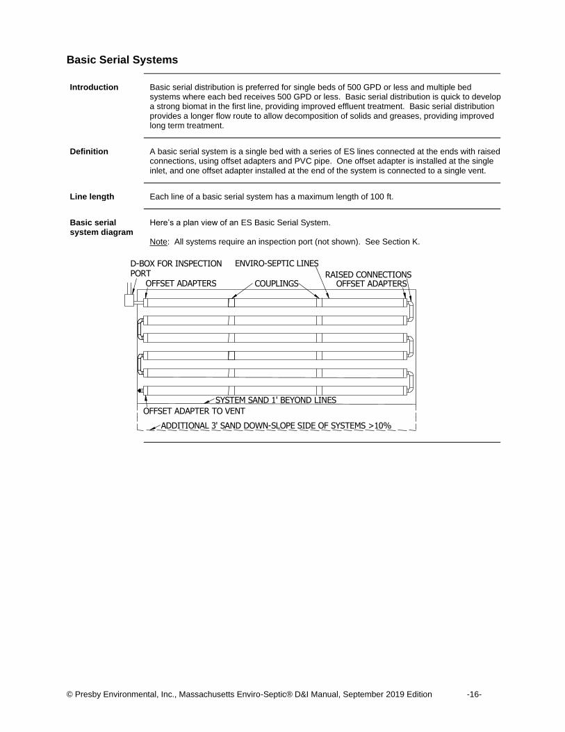
Definition A basic serial system is a single bed with a series of ES lines connected at the ends with raised
connections, using offset adapters and PVC pipe. One offset adapter is installed at the single inlet, and one offset adapter installed at the end of the system is connected to a single vent.
Line length Each line of a basic serial system has a maximum length of 100 ft.
Basic serial system diagram
Here’s a plan view of an ES Basic Serial System. Note: All systems require an inspection port (not shown). See Section K.
ENVIRO-SEPTIC LINES RAISED CONNECTIONS
SYSTEM SAND 1' BEYOND LINES OFFSET ADAPTER TO VENT
OFFSET ADAPTERS OFFSET ADAPTERS COUPLINGS
D-BOX FOR INSPECTION PORT
ADDITIONAL 3' SAND DOWN-SLOPE SIDE OF SYSTEMS >10%

© Presby Environmental, Inc., Massachusetts Enviro-Septic® D&I Manual, September 2019 Edition -17-
Combination Systems
Introduction Combination distribution is required for systems with greater than 500 GPD and for multiple bed
systems where each section receives no greater than 500 GPD. Combination distribution is quick to develop a strong biomat in the first line of each section providing improved effluent treatment. All systems require a distribution box for use as an observation port. Combination systems also use the same distribution box for dividing flow to multiple serial sections to provide longer flow routes to allow decomposition of solids and greases, providing improved long term treatment.
Definition A combination system is a bed of two or more sections of ES lines in serial configuration
supplied equally through a distribution box. Each section of a combination system is a series of ES lines connected at the ends with raised connections, using offset adapters and PVC sewer and drainpipe. An offset adapter is installed at each section inlet, and at the end of each section where it is connected to a vent or vent manifold.
Loading Each section of a combination system has a maximum design flow of 500 GPD.
Flow equalizers required
All distribution boxes that divide effluent flow in pump or gravity systems require flow equalizers in their outlets. Most flow equalizers are limited to a maximum of 10 gallons/minute in gravity systems and 20 gallons/minute in pumped systems. Note: To prevent movement, be sure distribution boxes are placed on a stable soil base or
concrete pad.
Line length Each line of a combination system has a maximum length of 100 ft.
Section length requirement
Each section of a combination system must have at least the same minimum linear feet of pipe. The minimum linear feet of pipe per section is determined by dividing the total linear feet required by the number of sections. A section may exceed the minimum linear length. Lines within a section may vary in length to accommodate site constraints.
Combination system diagram
Here’s a plan view of an ES combination system. Note: Inspection Port required (not shown). Refer to Section K.
SE
CT
ION
#2
SE
CT
ION
#1
D-BOX INSPECTION PORT/FLOW DIVIDER
OFFSET ADAPTERS
ENVIRO-SEPTIC LINES
COUPLINGS RAISED CONNECTIONS
OFFSET ADAPTERS
SYSTEM SAND 1' BEYOND LINES OFFSET ADAPTER TO VENT MANIFOLD
ADDITIONAL 3' SAND DOWN-SLOPE SIDE OF SYSTEMS >10%
© Presby Environmental, Inc., Massachusetts Enviro-Septic® D&I Manual, September 2019 Edition -18-
Distribution Box Systems
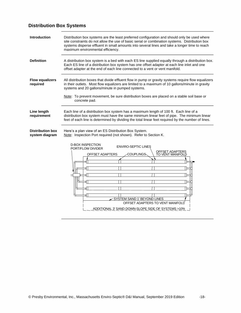
Introduction Distribution box systems are the least preferred configuration and should only be used where
site constraints do not allow the use of basic serial or combination systems. Distribution box systems disperse effluent in small amounts into several lines and take a longer time to reach maximum environmental efficiency.
Definition A distribution box system is a bed with each ES line supplied equally through a distribution box.
Each ES line of a distribution box system has one offset adapter at each line inlet and one offset adapter at the end of each line connected to a vent or vent manifold.
Flow equalizers required
All distribution boxes that divide effluent flow in pump or gravity systems require flow equalizers in their outlets. Most flow equalizers are limited to a maximum of 10 gallons/minute in gravity systems and 20 gallons/minute in pumped systems. Note: To prevent movement, be sure distribution boxes are placed on a stable soil base or
concrete pad.
Line length requirement
Each line of a distribution box system has a maximum length of 100 ft. Each line of a distribution box system must have the same minimum linear feet of pipe. The minimum linear feet of each line is determined by dividing the total linear feet required by the number of lines.
Distribution box system diagram
Here’s a plan view of an ES Distribution Box System. Note: Inspection Port required (not shown). Refer to Section K.
SYSTEM SAND 1' BEYOND LINES OFFSET ADAPTERS TO VENT MANIFOLD
ADDITIONAL 3' SAND DOWN-SLOPE SIDE OF SYSTEMS >10%
TO VENT MANIFOLD
ENVIRO-SEPTIC LINES
COUPLINGS OFFSET ADAPTERS
D-BOX INSPECTION PORT/FLOW DIVIDER
OFFSET ADAPTERS
© Presby Environmental, Inc., Massachusetts Enviro-Septic® D&I Manual, September 2019 Edition -19-
Multiple Bed Systems
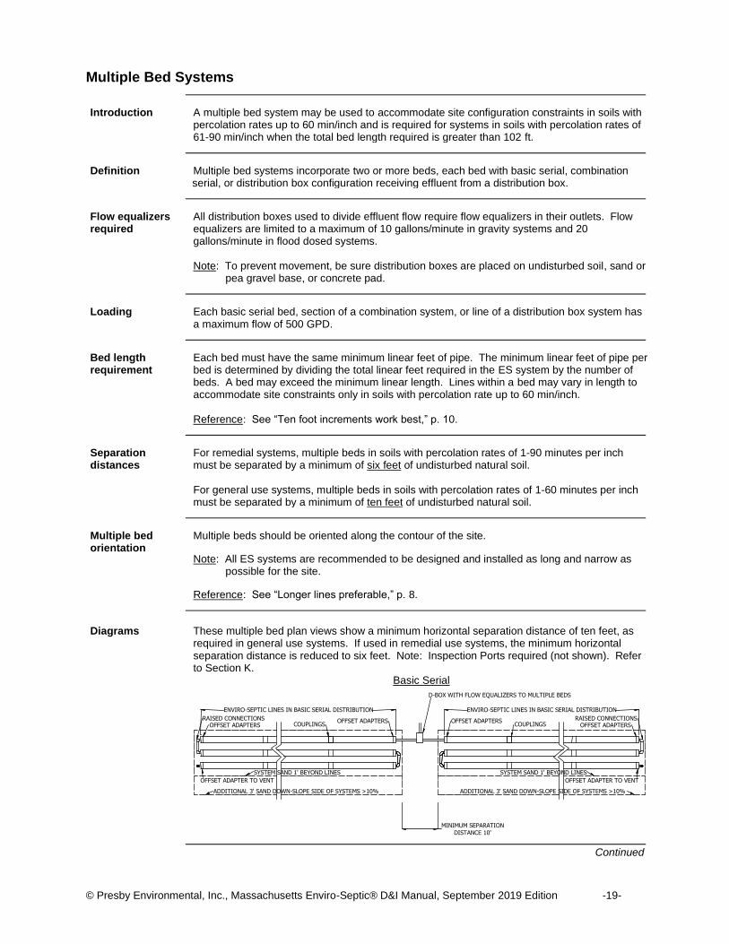
Introduction A multiple bed system may be used to accommodate site configuration constraints in soils with
percolation rates up to 60 min/inch and is required for systems in soils with percolation rates of 61-90 min/inch when the total bed length required is greater than 102 ft.
Definition Multiple bed systems incorporate two or more beds, each bed with basic serial, combination
serial, or distribution box configuration receiving effluent from a distribution box.
Flow equalizers required
All distribution boxes used to divide effluent flow require flow equalizers in their outlets. Flow equalizers are limited to a maximum of 10 gallons/minute in gravity systems and 20 gallons/minute in flood dosed systems. Note: To prevent movement, be sure distribution boxes are placed on undisturbed soil, sand or
pea gravel base, or concrete pad.
Loading Each basic serial bed, section of a combination system, or line of a distribution box system has
a maximum flow of 500 GPD.
Bed length requirement
Each bed must have the same minimum linear feet of pipe. The minimum linear feet of pipe per bed is determined by dividing the total linear feet required in the ES system by the number of beds. A bed may exceed the minimum linear length. Lines within a bed may vary in length to accommodate site constraints only in soils with percolation rate up to 60 min/inch. Reference: See “Ten foot increments work best,” p. 10.
Separation distances
For remedial systems, multiple beds in soils with percolation rates of 1-90 minutes per inch must be separated by a minimum of six feet of undisturbed natural soil. For general use systems, multiple beds in soils with percolation rates of 1-60 minutes per inch must be separated by a minimum of ten feet of undisturbed natural soil.
Multiple bed orientation
Multiple beds should be oriented along the contour of the site.
Note: All ES systems are recommended to be designed and installed as long and narrow as possible for the site.
Reference: See “Longer lines preferable,” p. 8.
Diagrams These multiple bed plan views show a minimum horizontal separation distance of ten feet, as
required in general use systems. If used in remedial use systems, the minimum horizontal separation distance is reduced to six feet. Note: Inspection Ports required (not shown). Refer to Section K.
Basic Serial
Continued
D-BOX WITH FLOW EQUALIZERS TO MULTIPLE BEDS
OFFSET ADAPTERS COUPLINGS RAISED CONNECTIONS
OFFSET ADAPTERS ENVIRO-SEPTIC LINES IN BASIC SERIAL DISTRIBUTION
RAISED CONNECTIONS OFFSET ADAPTERS OFFSET ADAPTERS
COUPLINGS ENVIRO-SEPTIC LINES IN BASIC SERIAL DISTRIBUTION
MINIMUM SEPARATION DISTANCE 10'
SYSTEM SAND 1' BEYOND LINES OFFSET ADAPTER TO VENT
ADDITIONAL 3' SAND DOWN-SLOPE SIDE OF SYSTEMS >10% ADDITIONAL 3' SAND DOWN-SLOPE SIDE OF SYSTEMS >10% OFFSET ADAPTER TO VENT
SYSTEM SAND 1' BEYOND LINES

© Presby Environmental, Inc., Massachusetts Enviro-Septic® D&I Manual, September 2019 Edition -20-
Multiple Bed Systems, Continued
Diagrams Continued
Combination Serial
Distribution Box
D-BOXES WITH FLOW EQUALIZERS
ENVIRO-SEPTIC LINES IN DISTRIBUTION BOX CONFIGURATION OFFSET ADAPTERS COUPLINGS RAISED CONNECTIONS
OFFSET ADAPTERS
SYSTEM SAND 1' BEYOND LINES OFFSET ADAPTERS TO VENT MANIFOLD
ADDITIONAL 3' SAND DOWN-SLOPE SIDE OF SYSTEMS >10% OFFSET ADAPTERS TO VENT MANIFOLD
ADDITIONAL 3' SAND DOWN-SLOPE SIDE OF SYSTEMS >10%
SYSTEM SAND 1' BEYOND LINES
OFFSET ADAPTERS COUPLINGS OFFSET ADAPTERS ENVIRO-SEPTIC LINES IN DISTRIBUTION BOX CONFIGURATION
RAISED CONNECTIONS
MINIMUM SEPARATION DISTANCE 10'
D-BOX WITH FLOW EQUALIZERS TO MULTIPLE BEDS
ENVIRO-SEPTIC LINES IN COMBINATION SERIAL DISTRIBUTION
MINIMUM SEPARATION DISTANCE 10'
SECTIO
N #
4
SECTIO
N #
3
OFFSET ADAPTERS COUPLINGS RAISED CONNECTIONS
OFFSET ADAPTERS
ENVIRO-SEPTIC LINES IN COMBINATION SERIAL DISTRIBUTION
SECTIO
N #
2
SECTIO
N #
1
COUPLINGS OFFSET ADAPTERS RAISED CONNECTIONS OFFSET ADAPTERS
SYSTEM SAND 1' BEYOND LINES OFFSET ADAPTER TO VENT
ADDITIONAL 3' SAND DOWN-SLOPE SIDE OF SYSTEMS >10% ADDITIONAL 3' SAND DOWN-SLOPE SIDE OF SYSTEMS >10% OFFSET ADAPTER TO VENT
SYSTEM SAND 1' BEYOND LINES
© Presby Environmental, Inc., Massachusetts Enviro-Septic® D&I Manual, September 2019 Edition -21-
Inground System Sections
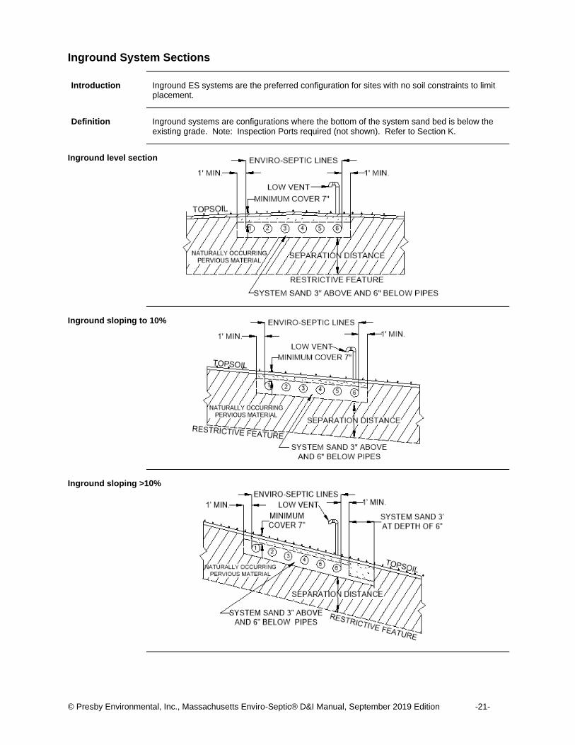
Introduction Inground ES systems are the preferred configuration for sites with no soil constraints to limit
placement.
Definition Inground systems are configurations where the bottom of the system sand bed is below the
existing grade. Note: Inspection Ports required (not shown). Refer to Section K.
Inground level section
Inground sloping to 10%
Inground sloping >10%
© Presby Environmental, Inc., Massachusetts Enviro-Septic® D&I Manual, September 2019 Edition -22-
Raised (Mounds) System Sections
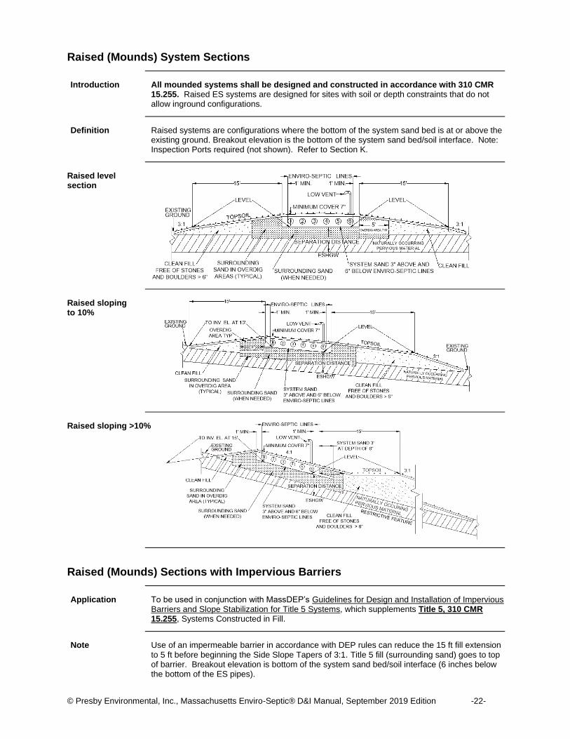
Introduction All mounded systems shall be designed and constructed in accordance with 310 CMR
15.255. Raised ES systems are designed for sites with soil or depth constraints that do not allow inground configurations.
Definition Raised systems are configurations where the bottom of the system sand bed is at or above the
existing ground. Breakout elevation is the bottom of the system sand bed/soil interface. Note: Inspection Ports required (not shown). Refer to Section K.
Raised level section
Raised sloping to 10%
Raised sloping >10%
Raised (Mounds) Sections with Impervious Barriers
Application To be used in conjunction with MassDEP’s Guidelines for Design and Installation of Impervious
Barriers and Slope Stabilization for Title 5 Systems, which supplements Title 5, 310 CMR 15.255, Systems Constructed in Fill.
Note Use of an impermeable barrier in accordance with DEP rules can reduce the 15 ft fill extension
to 5 ft before beginning the Side Slope Tapers of 3:1. Title 5 fill (surrounding sand) goes to top of barrier. Breakout elevation is bottom of the system sand bed/soil interface (6 inches below the bottom of the ES pipes).
© Presby Environmental, Inc., Massachusetts Enviro-Septic® D&I Manual, September 2019 Edition -23-
Section H Non-Standard System Configurations
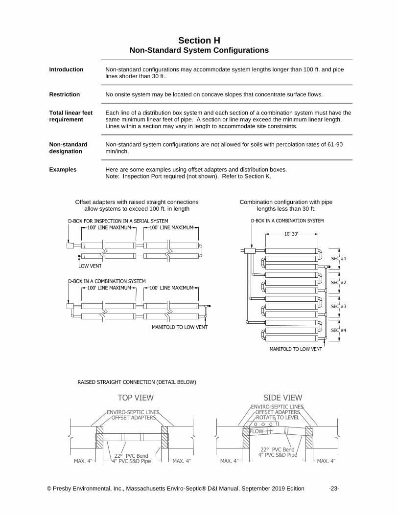
Introduction Non-standard configurations may accommodate system lengths longer than 100 ft. and pipe
lines shorter than 30 ft..
Restriction No onsite system may be located on concave slopes that concentrate surface flows.
Total linear feet requirement
Each line of a distribution box system and each section of a combination system must have the same minimum linear feet of pipe. A section or line may exceed the minimum linear length. Lines within a section may vary in length to accommodate site constraints.
Non-standard designation
Non-standard system configurations are not allowed for soils with percolation rates of 61-90 min/inch.
Examples Here are some examples using offset adapters and distribution boxes.
Note: Inspection Port required (not shown). Refer to Section K.
Combination configuration with pipe lengths less than 30 ft.
RAISED STRAIGHT CONNECTION (DETAIL BELOW)
Offset adapters with raised straight connections allow systems to exceed 100 ft. in length
100' LINE MAXIMUM 100' LINE MAXIMUM
100' LINE MAXIMUM 100' LINE MAXIMUM
MANIFOLD TO LOW VENT
LOW VENT
D-BOX FOR INSPECTION IN A SERIAL SYSTEM
D-BOX IN A COMBINATION SYSTEM
SEC #1
SEC #2
SEC #3
SEC #4
D-BOX IN A COMBINATION SYSTEM
MANIFOLD TO LOW VENT
10'-30'
4" PVC S&D Pipe
OFFSET ADAPTERS
22° PVC Bend
ENVIRO-SEPTIC LINES
TOP VIEW
MAX. 4" MAX. 4"
ENVIRO-SEPTIC LINES
MAX. 4" MAX. 4" 4" PVC S&D Pipe 22° PVC Bend
OFFSET ADAPTERS
SIDE VIEW
FLOW
ROTATE TO LEVEL
© Presby Environmental, Inc., Massachusetts Enviro-Septic® D&I Manual, September 2019 Edition -24-
Non-Standard System Configurations, Continued
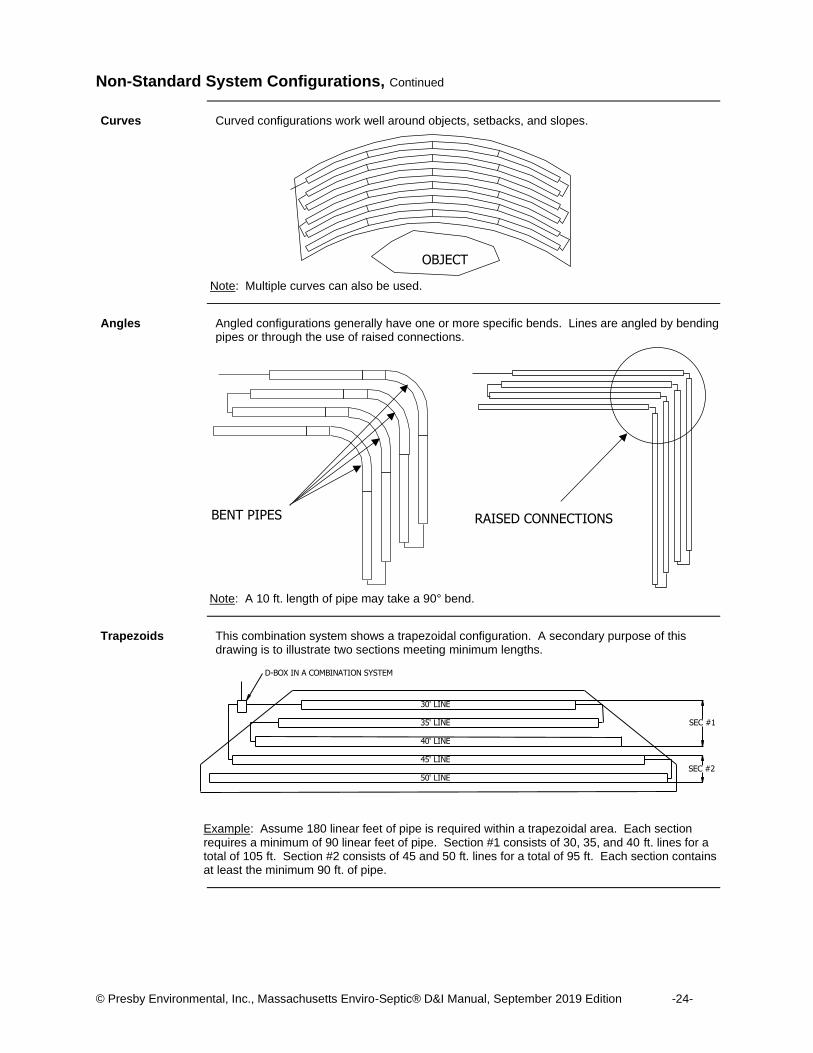
Curves Curved configurations work well around objects, setbacks, and slopes.
Note: Multiple curves can also be used.
Angles Angled configurations generally have one or more specific bends. Lines are angled by bending
pipes or through the use of raised connections.
Note: A 10 ft. length of pipe may take a 90° bend.
Trapezoids This combination system shows a trapezoidal configuration. A secondary purpose of this
drawing is to illustrate two sections meeting minimum lengths.
Example: Assume 180 linear feet of pipe is required within a trapezoidal area. Each section requires a minimum of 90 linear feet of pipe. Section #1 consists of 30, 35, and 40 ft. lines for a total of 105 ft. Section #2 consists of 45 and 50 ft. lines for a total of 95 ft. Each section contains at least the minimum 90 ft. of pipe.
OBJECT
D-BOX IN A COMBINATION SYSTEM
SEC #1
SEC #2
30' LINE 35' LINE 40' LINE 45' LINE 50' LINE
RAISED CONNECTIONS BENT PIPES
© Presby Environmental, Inc., Massachusetts Enviro-Septic® D&I Manual, September 2019 Edition -25-
Section I Pump System Requirements
Introduction Pump systems typically supply effluent to ES pipe using a pressured line and a distribution box
as a velocity reducer when site conditions do not permit a gravity system. Pumps and chambers shall be designed in accordance with 310 CMR 15.231.
Differential venting
All pump systems must use differential venting. Reference: See Section J, “Venting Requirements,” p. 26.
Velocity control It is important to control the rate at which effluent enters ES pipe. Excessive effluent velocity
can disrupt suspended solids that have settled out in the pipes.
Velocity reduction Never pump effluent directly into ES pipes. Pressurized lines must discharge into a velocity
reducing distribution box with a baffle, a 90-degree elbow, or a tee fitting. If the design already incorporates a distribution box to divide effluent flow, an additional distribution box may not be necessary.
Pipe length per pumped gallon
Each gallon of effluent pumped per cycle requires a minimum of 1.0 ft. of ES pipe.
Basic System GPM Limit
A maximum of 40 GPM is permitted for each basic serial bed.
GPM per flow equalizer limit
A flow equalizer used in a pump system is limited to a maximum of 20 gallons per minute.
Section or line GPM limit
Each line of a pumped D-box system or each section of a pumped combination system is limited to a maximum of 20 GPM. Each basic serial bed without a flow equalizer can have a maximum flow of 40 GPM.
Pump cycling Pump cycling is recommended to be six or more cycles per day.
© Presby Environmental, Inc., Massachusetts Enviro-Septic® D&I Manual, September 2019 Edition -26-
Section J Venting Requirements
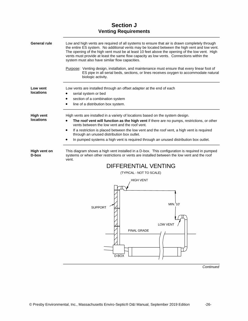
General rule Low and high vents are required of all systems to ensure that air is drawn completely through
the entire ES system. No additional vents may be located between the high vent and low vent. The opening of the high vent must be at least 10 feet above the opening of the low vent. High vents must provide at least the same flow capacity as low vents. Connections within the system must also have similar flow capacities. Purpose: Venting design, installation, and maintenance must ensure that every linear foot of
ES pipe in all serial beds, sections, or lines receives oxygen to accommodate natural biologic activity.
Low vent locations
Low vents are installed through an offset adapter at the end of each
• serial system or bed
• section of a combination system
• line of a distribution box system.
High vent locations
High vents are installed in a variety of locations based on the system design.
• The roof vent will function as the high vent if there are no pumps, restrictions, or other vents between the low vent and the roof vent.
• If a restriction is placed between the low vent and the roof vent, a high vent is required through an unused distribution box outlet.
• In pumped systems a high vent is required through an unused distribution box outlet.
High vent on D-box
This diagram shows a high vent installed in a D-box. This configuration is required in pumped systems or when other restrictions or vents are installed between the low vent and the roof vent.
Continued
DIFFERENTIAL VENTING
(TYPICAL - NOT TO SCALE)
MIN. 10'
FINAL GRADE
HIGH VENT
D-BOX
SUPPORT
LOW VENT
© Presby Environmental, Inc., Massachusetts Enviro-Septic® D&I Manual, September 2019 Edition -27-
SLOPE
SLOPE
BY-PASS VENT
ATTACH BY-PASS VENT TO
PUMP CHAMBER OR UNUSED
OPENING IN SEPTIC TANK
WHEN USING BY-PASS VENTING THE ROOF VENT
REPLACES THE "HIGH" VENT AND PUMP CHAMBER
VENT (IF REQ'D). THE OPENING OF ROOF VENT MUST
BE AT LEAST 10 FT. ABOVE OPENING OF LOW VENT
D-BOX
FINISH GRADE
SEPTIC TANK WITH
SANITARY TEE BAFFLESPUMP
CHAMBER
BY-PASS VENTING REPLACES BOTH
THE HIGH VENT AND PUMP CHAMBER
VENT (IF REQUIRED)
EL
IMIN
AT
ED
LOW VENT IS AIR
INTAKE
ENILPMUP
TO D-BOX
NO EFFLUENT
FILTER
ADD PUMP CHAMBER BY-PASS VENT IF EFFLUENT
FILTER IS USED ON SEPTIC TANK OUTLET BAFFLE
A
A
PUMP CHAMBER BY-PASS
VENT HIGHER THAN INLET
& ABOVE TOP OF TANK
VIEW A-A(ROTATED 90°)
SEPTIC TANK
OPTIONAL CONFIGURATION(IF EFFLUENT FILTER USED)
SEPTIC TANK
PUMP BOX
10' MIN
3'
PMUPLIN
E
PRESBY FIELD
NOTES:
1. NOT TO BE USED WITH GRAVITY SYSTEMS.
2. INVERT OF PIPE EXITING D-BOX MUST RISE
2" MINIMUM ABOVE D-BOX.
3. USE 4" SCH. 40 PVC OR EQUAL FOR BY-PASS
VENTING.
4. GLUE ALL PVC JOINTS OR EQUAL.
Venting Requirements, Continued
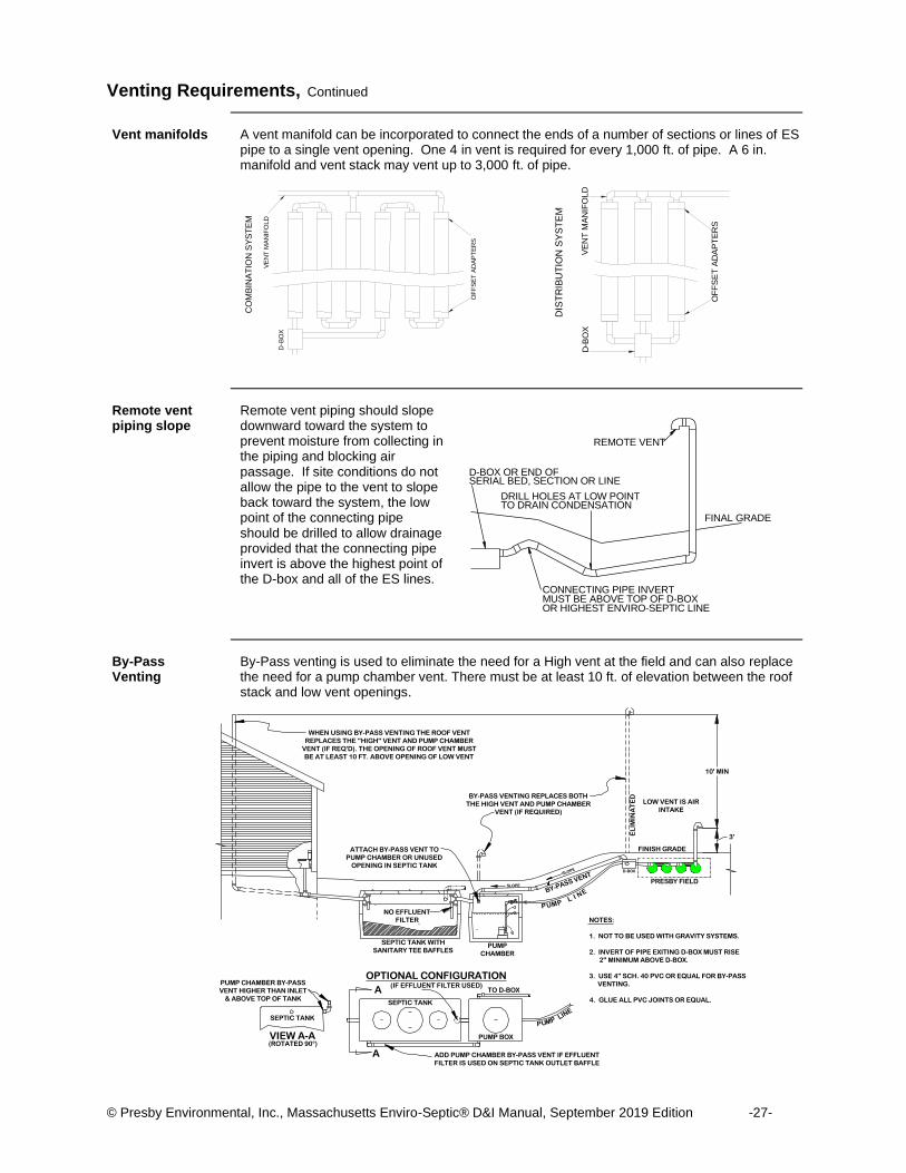
Vent manifolds A vent manifold can be incorporated to connect the ends of a number of sections or lines of ES
pipe to a single vent opening. One 4 in vent is required for every 1,000 ft. of pipe. A 6 in. manifold and vent stack may vent up to 3,000 ft. of pipe.
Remote vent piping slope
Remote vent piping should slope downward toward the system to prevent moisture from collecting in the piping and blocking air passage. If site conditions do not allow the pipe to the vent to slope back toward the system, the low point of the connecting pipe should be drilled to allow drainage provided that the connecting pipe invert is above the highest point of the D-box and all of the ES lines.
By-Pass Venting
By-Pass venting is used to eliminate the need for a High vent at the field and can also replace the need for a pump chamber vent. There must be at least 10 ft. of elevation between the roof stack and low vent openings.
OF
FS
ET
AD
AP
TE
RS
CO
MB
INA
TIO
N S
YS
TE
M
D - B
OX
VE
NT
MA
NIF
OLD
OF
FS
ET
AD
AP
TE
RS
D - B
OX
VE
NT
MA
NIF
OLD
DIS
TR
IBU
TIO
N S
YS
TE
M
OR HIGHEST ENVIRO - SEPTIC LINE MUST BE ABOVE TOP OF D - BOX CONNECTING PIPE INVERT
TO DRAIN CONDENSATION DRILL HOLES AT LOW POINT
SERIAL BED, SECTION OR LINE D - BOX OR END OF
REMOTE VENT
FINAL GRADE
© Presby Environmental, Inc., Massachusetts Enviro-Septic® D&I Manual, September 2019 Edition -28-
Section K Inspection Port Requirements
Massachusetts requires inspection ports
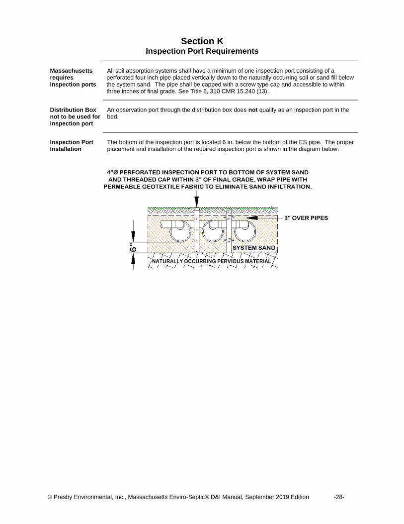
All soil absorption systems shall have a minimum of one inspection port consisting of a perforated four inch pipe placed vertically down to the naturally occurring soil or sand fill below the system sand. The pipe shall be capped with a screw type cap and accessible to within three inches of final grade. See Title 5, 310 CMR 15.240 (13).
Distribution Box not to be used for inspection port
An observation port through the distribution box does not qualify as an inspection port in the bed.
Inspection Port Installation
The bottom of the inspection port is located 6 in. below the bottom of the ES pipe. The proper placement and installation of the required inspection port is shown in the diagram below.
© Presby Environmental, Inc., Massachusetts Enviro-Septic® D&I Manual, September 2019 Edition -29-
Section L Bottom Drains and Requirements
Purpose Bottom drains aid in the rejuvenation of overloaded or abused systems and are recommended
for commercial systems at risk of misuse, under pavement, or in inaccessible areas. Bottom drains allow effluent to be pumped from systems without requiring excavation. Once pumped, systems may be rejuvenated instead of replaced.
Requirements Bottom drains connect to sealed drain sumps. Here are some drain requirements.
• The top of the drain sump should be a minimum of 12 in. above the top of the highest ES pipe.
• The bottom drain inlet must be a minimum of 18 in. above the drain sump floor.
• Level systems may use single drain sumps.
• Sloping systems may require multiple drain sumps.
• All bottom drain connections and drain sumps must be sealed.
• Connect bottom drain to every row, even when system is configured in Basic or Combination Serial configuration. This will allow the entire field to drain when the sump is pumped out.
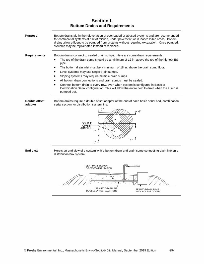
Double offset adapter
Bottom drains require a double offset adapter at the end of each basic serial bed, combination serial section, or distribution system line.
End view Here’s an end view of a system with a bottom drain and drain sump connecting each line on a
distribution box system.
OFFSET DOUBLE
ADAPTER
SEALED DRAIN SUMP SEALED DRAIN LINE
VENT
WITH ACCESS COVER DOUBLE OFFSET ADAPTERS
D-BOX CONFIGURATION VENT MANIFOLD ON
© Presby Environmental, Inc., Massachusetts Enviro-Septic® D&I Manual, September 2019 Edition -30-
Section M System Rejuvenation and Expansion
Introduction This section covers procedures for rejuvenating systems installed according to this manual but
failing because of misuse. It also explains how to expand existing systems.
Why systems fail System failures related to misuse or lack of oxygen, almost without exception, are related to the
conversion of bacteria from an aerobic to an anaerobic state. Flooding, improper venting, alteration or lack of oxygen, sudden use changes, introduction of chemicals or medicines, and a variety of other conditions can contribute to this problem.
Rejuvenating failing systems
Failing systems need to be returned from an anaerobic to an aerobic state. Most ES systems can be put back on line and not require costly removal and replacement by using the following procedure. 1. Determine the problem causing system failure and repair. 2. Drain the system by pumping out the sump of a bottom drain or by excavating one end of
all the lines and removing the end cap or offset adapter. 3. Drain the lines. 4. If foreign matter has entered the system, flush the pipes. 5. Safeguard the open excavation. 6. Guarantee a passage of air through the system. 7. Allow all lines to dry for a minimum of 72 hours. 8. Manually excavate a small area of system sand adjacent to the pipe.
Note: System sand in failed systems is blackened by anaerobic bacteria. Rejuvenation returns the sand to nearly its original color.
9. When the system sand color has returned, re-assemble the system to its original design configuration.
System expansion ES systems are easily expanded by adding equal lengths of pipe to each line of the original
design or by adding additional equal sections. Note: All system expansions need to meet State and/or local regulations.
Re-usable pipe ES components are not biodegradable and may be reused. In cases of improper installation, it
may be possible to excavate, clean, and reinstall all ES system components.
System replacement
If system components are damaged, remove and replace.
© Presby Environmental, Inc., Massachusetts Enviro-Septic® D&I Manual, September 2019 Edition -31-
Section N Quick Reference Guide for Percolation Rates Up to 60 Minutes/Inch
Purpose The unique ES design provides an infinite number of system configurations that vary in length,
width, slope, and shape. The purpose of this guide is to help designers compare layouts for any site quickly and easily. We recommend designers read this entire manual before using this Quick Reference Guide.
Exceptions require variance
Exceptions to any requirements used in this quick reference guide require a variance from the local approving authority.
Minimum separation distances
Title 5, 310 CMR 15.000 of the State Environmental Code establishes rules for minimum vertical and horizontal separation distances. Setback distances are measured from the outer edge of the required system sand. The distances to EHGW and other restrictive features are measured from the bottom of the 6 in. of system sand below the ES pipe.
System configuration
Basic serial configuration is recommended for low flow systems. High flow systems are preferably designed as combination systems or multiple serial bed systems, but distribution box systems may also be used.
Procedure Complete these tasks to size a single level ES system.
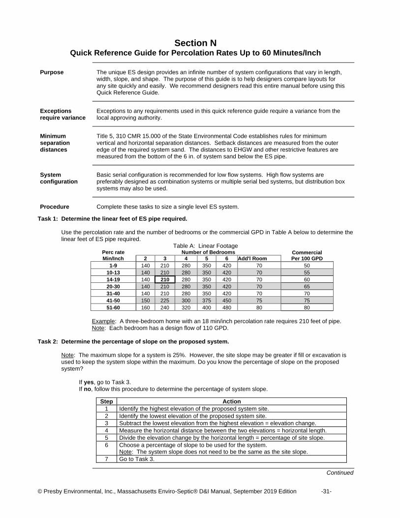
Task 1: Determine the linear feet of ES pipe required.
Use the percolation rate and the number of bedrooms or the commercial GPD in Table A below to determine the linear feet of ES pipe required.
Table A: Linear Footage Perc rate Number of Bedrooms Commercial
Per 100 GPD Min/Inch 2 3 4 5 6 Add'l Room
1-9 140 210 280 350 420 70 50
10-13 140 210 280 350 420 70 55
14-19 140 210 280 350 420 70 60
20-30 140 210 280 350 420 70 65
31-40 140 210 280 350 420 70 70
41-50 150 225 300 375 450 75 75
51-60 160 240 320 400 480 80 80
Example: A three-bedroom home with an 18 min/inch percolation rate requires 210 feet of pipe. Note: Each bedroom has a design flow of 110 GPD.
Task 2: Determine the percentage of slope on the proposed system.
Note: The maximum slope for a system is 25%. However, the site slope may be greater if fill or excavation is used to keep the system slope within the maximum. Do you know the percentage of slope on the proposed system?
If yes, go to Task 3. If no, follow this procedure to determine the percentage of system slope.
Step Action
1 Identify the highest elevation of the proposed system site.
2 Identify the lowest elevation of the proposed system site.
3 Subtract the lowest elevation from the highest elevation = elevation change.
4 Measure the horizontal distance between the two elevations = horizontal length.
5 Divide the elevation change by the horizontal length = percentage of site slope.
6 Choose a percentage of slope to be used for the system. Note: The system slope does not need to be the same as the site slope.
7 Go to Task 3.
Continued
© Presby Environmental, Inc., Massachusetts Enviro-Septic® D&I Manual, September 2019 Edition -32-
Quick Reference Guide for Percolation Rates Up to 60 Minutes/Inch, Continued
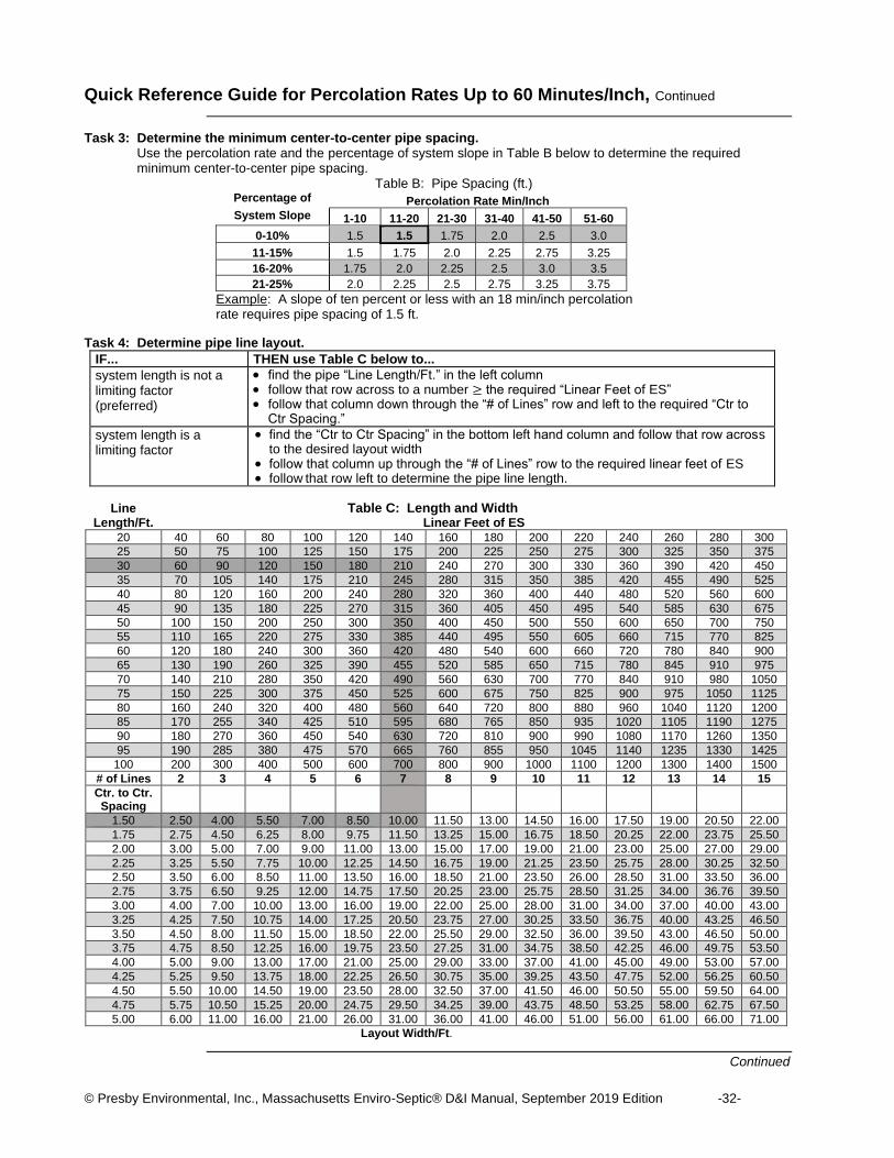
Task 3: Determine the minimum center-to-center pipe spacing. Use the percolation rate and the percentage of system slope in Table B below to determine the required minimum center-to-center pipe spacing.
Table B: Pipe Spacing (ft.) Percentage of Percolation Rate Min/Inch
System Slope 1-10 11-20 21-30 31-40 41-50 51-60
0-10% 1.5 1.5 1.75 2.0 2.5 3.0
11-15% 1.5 1.75 2.0 2.25 2.75 3.25
16-20% 1.75 2.0 2.25 2.5 3.0 3.5
21-25% 2.0 2.25 2.5 2.75 3.25 3.75
Example: A slope of ten percent or less with an 18 min/inch percolation rate requires pipe spacing of 1.5 ft.
Task 4: Determine pipe line layout.
IF... THEN use Table C below to...
system length is not a limiting factor (preferred)
• find the pipe “Line Length/Ft.” in the left column • follow that row across to a number ≥ the required “Linear Feet of ES” • follow that column down through the “# of Lines” row and left to the required “Ctr to
Ctr Spacing.”
system length is a limiting factor
• find the “Ctr to Ctr Spacing” in the bottom left hand column and follow that row across to the desired layout width
• follow that column up through the “# of Lines” row to the required linear feet of ES • follow that row left to determine the pipe line length.
Line Table C: Length and Width Length/Ft. Linear Feet of ES
20 40 60 80 100 120 140 160 180 200 220 240 260 280 300
25 50 75 100 125 150 175 200 225 250 275 300 325 350 375
30 60 90 120 150 180 210 240 270 300 330 360 390 420 450
35 70 105 140 175 210 245 280 315 350 385 420 455 490 525
40 80 120 160 200 240 280 320 360 400 440 480 520 560 600
45 90 135 180 225 270 315 360 405 450 495 540 585 630 675
50 100 150 200 250 300 350 400 450 500 550 600 650 700 750
55 110 165 220 275 330 385 440 495 550 605 660 715 770 825
60 120 180 240 300 360 420 480 540 600 660 720 780 840 900
65 130 190 260 325 390 455 520 585 650 715 780 845 910 975
70 140 210 280 350 420 490 560 630 700 770 840 910 980 1050
75 150 225 300 375 450 525 600 675 750 825 900 975 1050 1125
80 160 240 320 400 480 560 640 720 800 880 960 1040 1120 1200
85 170 255 340 425 510 595 680 765 850 935 1020 1105 1190 1275
90 180 270 360 450 540 630 720 810 900 990 1080 1170 1260 1350
95 190 285 380 475 570 665 760 855 950 1045 1140 1235 1330 1425
100 200 300 400 500 600 700 800 900 1000 1100 1200 1300 1400 1500
# of Lines 2 3 4 5 6 7 8 9 10 11 12 13 14 15
Ctr. to Ctr. Spacing
1.50 2.50 4.00 5.50 7.00 8.50 10.00 11.50 13.00 14.50 16.00 17.50 19.00 20.50 22.00
1.75 2.75 4.50 6.25 8.00 9.75 11.50 13.25 15.00 16.75 18.50 20.25 22.00 23.75 25.50
2.00 3.00 5.00 7.00 9.00 11.00 13.00 15.00 17.00 19.00 21.00 23.00 25.00 27.00 29.00
2.25 3.25 5.50 7.75 10.00 12.25 14.50 16.75 19.00 21.25 23.50 25.75 28.00 30.25 32.50
2.50 3.50 6.00 8.50 11.00 13.50 16.00 18.50 21.00 23.50 26.00 28.50 31.00 33.50 36.00
2.75 3.75 6.50 9.25 12.00 14.75 17.50 20.25 23.00 25.75 28.50 31.25 34.00 36.76 39.50
3.00 4.00 7.00 10.00 13.00 16.00 19.00 22.00 25.00 28.00 31.00 34.00 37.00 40.00 43.00
3.25 4.25 7.50 10.75 14.00 17.25 20.50 23.75 27.00 30.25 33.50 36.75 40.00 43.25 46.50
3.50 4.50 8.00 11.50 15.00 18.50 22.00 25.50 29.00 32.50 36.00 39.50 43.00 46.50 50.00
3.75 4.75 8.50 12.25 16.00 19.75 23.50 27.25 31.00 34.75 38.50 42.25 46.00 49.75 53.50
4.00 5.00 9.00 13.00 17.00 21.00 25.00 29.00 33.00 37.00 41.00 45.00 49.00 53.00 57.00
4.25 5.25 9.50 13.75 18.00 22.25 26.50 30.75 35.00 39.25 43.50 47.75 52.00 56.25 60.50
4.50 5.50 10.00 14.50 19.00 23.50 28.00 32.50 37.00 41.50 46.00 50.50 55.00 59.50 64.00
4.75 5.75 10.50 15.25 20.00 24.75 29.50 34.25 39.00 43.75 48.50 53.25 58.00 62.75 67.50
5.00 6.00 11.00 16.00 21.00 26.00 31.00 36.00 41.00 46.00 51.00 56.00 61.00 66.00 71.00
Layout Width/Ft.
Continued

© Presby Environmental, Inc., Massachusetts Enviro-Septic® D&I Manual, September 2019 Edition -33-
Quick Reference Guide for Percolation Rates Up to 60 Minutes/Inch, Continued
Task 5: Calculate the total system sand bed area. Massachusetts requires that ES systems be no less than 60% of the area of a pipe and aggregate system and no less than 400 square feet. Complete this task to determine area size. Add two feet to the layout width and line length from Table C and multiply them together to obtain the sand bed area in sq. ft. For sloping systems greater than 10%, add 5 ft. to the system width and two feet to the pipe length and multiply them together. (The 5 ft. width accounts for the 4 ft. sand bed extension required on slopes of 10% or more.) If the area calculated above is less than the minimum sand bed area size required by Massachusetts in Table D, see “Increasing sand bed area footage”, next page.
Table D – Minimum Sand bed Area Size (sq. ft.)
PERC 2 BEDROOM 220 GPD 3 BEDROOM 330 GPD 4 BEDROOM 440 GPD 5 BEDROOM 550 GPD
RATE* SOIL CLASS SOIL CLASS SOIL CLASS SOIL CLASS
Min/Inch I II III IV I II III IV I II III IV I II III IV
1-5 400 400 400 400 400 440 446 550
6 400 400 400 400 400 440 471 550
7 400 400 400 400 400 440 485 550
8 400 400 400 400 400 440 500 550
10 400 400 440 550
15 400 400 400 535 471 714 589 892
20 400 400 400 582 498 776 623 971
25 400 400 495 600 660 800 825 1000
30 400 455 600 683 800 910 1000 1138
40 528 792 1056 1320
50 660 660 990 990 1320 1320 1650 1650
60 880 880 1320 1320 1760 1760 2200 2200
PERC 6 BEDROOM 660 GPD ADD'L. BEDROOM 110 GPD COMMERCIAL PER 100 GPD
RATE* SOIL CLASS SOIL CLASS SOIL CLASS
Min/Inch I II III IV I II III IV I II III IV
1-5 535 660 89 110 81 100
6 566 660 94 110 86 100
7 582 660 97 110 88 100
8 600 660 100 110 91 100
10 660 110 100
15 707 1070 117 178 107 162
20 747 1165 124 194 113 176
25 990 1200 165 200 150 182
30 1200 1366 200 227 182 207
40 1584 264 240
50 1980 1980 330 330 300 300
60 2640 2640 440 440 400 400
*When percolation rate is between those listed in Table D, the next slower rate shall be used for design purposes.

© Presby Environmental, Inc., Massachusetts Enviro-Septic® D&I Manual, September 2019 Edition -34-
Quick Reference Guide for Percolation Rates of Up to 60 Minutes/Inch, Continued
Increasing sand bed area footage
Our 3-bedroom home requires 210 linear feet of pipe at 1.5 ft. on center. Using Table C, with 7-30 ft. lines the system width is 10 ft. with a sand bed area of 32 ft. x 12 ft. for a total of 384 sq. ft. of sand bed. To meet the Massachusetts minimum bed area requirement of 400 sq. ft. for soil class II from Table D, our sand bed area must be increased. Our sand bed area may be increased by adding width and/or length to the system. Adding width: To meet the minimum sand bed area size required, the minimum pipe spacing may be increased. Add 2 ft. to the pipe length and divide the minimum sand bed area size by that amount to obtain the minimum sand bed width. Subtract 2 ft. from the minimum sand bed width and find the line spacing that provides at least that layout width in Table C. For slopes greater than 10%, subtract 5 ft. from the minimum sand bed width before referring to Table C for line spacing. Adding width example: To increase the sand bed area footage in our example by adding width, divide 400 ft. by 32 ft. to obtain a minimum sand bed width of 12.5 ft. Subtract 2 ft. from that to obtain the minimum layout width of 10.5 ft. Table C indicates that a line spacing of 1.75 ft. on center provides a layout width of 10.5 ft. for a 7-line system, providing a sand bed width of 12.5 ft. to meet the required 12.5 ft. minimum sand bed width. This now gives us a sand bed area of 400 sq. ft. (12. ft. x 32 ft.) and a system configuration of 7-30 ft. lines spaced 1.75 ft. on center. Adding length: Add 2 ft. to the system width (5 ft. for slopes over 10%) and divide the minimum sand bed area size by that amount to obtain the minimum sand bed length required. Subtract 2 ft. from the minimum sand bed length to obtain the pipe line length. Adding length example: To increase the sand bed area footage in our example by adding length, divide 400 ft. by 12 ft. to obtain a sand bed length of 33.5 ft. Subtract 2 ft. from that to obtain a line length of 31.5 ft. 33.5 ft. x 12 ft. equals 402 sq. ft. of sand bed area. The system configuration would be 7-31.5 ft. lines spaced 1.5 ft. on center. Note: This example uses 7-31.5 ft. line lengths. Limiting pipe to 5 ft. and 10 ft. lengths makes
systems simpler to construct. This system would be more easily installed as 7-35 ft. lines, eliminating the need to cut the pipe.
© Presby Environmental, Inc., Massachusetts Enviro-Septic® D&I Manual, September 2019 Edition -35-
Section O Quick Reference Guide for Percolation Rates of 61-90 Minutes/Inch
Introduction Systems in high-density soils or soils with slow percolation rates are limited in configuration to
adequately disperse and treat effluent and minimize groundwater mounding.
Purpose The purpose of this guide is to help designers choose system layouts for percolation rates in
the 61-90 minutes/inch range. We recommend designers read this entire manual before using this Quick Reference Guide.
Restriction Installations in soils with percolation rates of 61-90 minutes/inch are restricted to remedial use
systems only.
Exceptions require variance
Exceptions to any requirements used in this quick reference guide require a variance from the local approving authority.
Minimum separation distances
Title 5, 310 CMR 15.000 of the State Environmental Code for Massachusetts establishes rules for minimum vertical and horizontal separation distances. Setback distances are measured from the outer edge of the required system sand. The distances to EHGW and other restrictive features are measured from the bottom of the 6 in. of system sand below the ES pipe.
Slope percentages allowed
Use Table E below to determine the maximum slope percentages allowed.
Table E – Maximum Slopes for Perc. Rates 61-90 Min./Inch
Perc. Rate % Slope
61-70 15%
71-90 10%
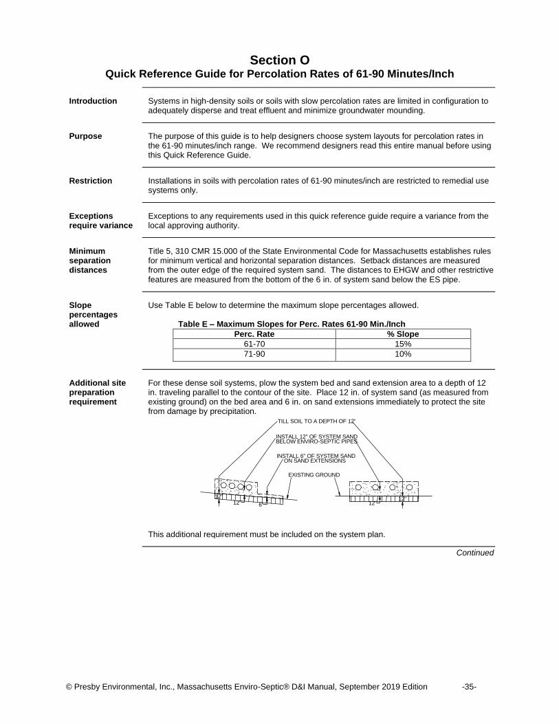
Additional site preparation requirement
For these dense soil systems, plow the system bed and sand extension area to a depth of 12 in. traveling parallel to the contour of the site. Place 12 in. of system sand (as measured from existing ground) on the bed area and 6 in. on sand extensions immediately to protect the site from damage by precipitation. This additional requirement must be included on the system plan.
Continued
TILL SOIL TO A DEPTH OF 12"
INSTALL 12" OF SYSTEM SAND BELOW ENVIRO-SEPTIC PIPES
6" 12"
INSTALL 6" OF SYSTEM SAND ON SAND EXTENSIONS
12" 12"
EXISTING GROUND
12"
© Presby Environmental, Inc., Massachusetts Enviro-Septic® D&I Manual, September 2019 Edition -36-
Quick Reference Guide for Percolation Rates of 61-90 Minutes/Inch, Continued
Procedure Complete these tasks to design a single level ES leaching system with percolation rates
between 61-90 minutes/inch.
Task 1: Determine the percentage of slope on the proposed system. Note: The maximum system slope is limited to 15% depending on percolation rates. However, the site
slope may be greater if fill or excavation is used to keep the system slope within the maximum. Do you know the percentage of slope on the proposed system? If yes, go to Task 2. If no, follow this procedure to determine the percentage of system slope.
Step Action
1 Identify the highest elevation of the proposed system site.
2 Identify the lowest elevation of the proposed system site.
3 Subtract the lowest elevation from the highest elevation = elevation change.
4 Measure the horizontal distance between the two elevations = horizontal length.
5 Divide the elevation change by the horizontal length = percentage of site slope.
6 Choose a percentage of slope to be used for the system. Note: The system slope does not need to be the same as the site slope.
7 Go to Task 2.
Task 2: Choose the proper sizing table.
Sizing tables use the number of bedrooms for homes or the GPD flow in commercial installations to determine system size. System size is the total square footage of sand bed area required for a system. Sand bed area is designed as one or more individual sand beds. Sand bed widths are pre-established at 12, 9, and 6 ft. Sand bed lengths vary according to percolation rates and slope percentages. Reference: See Level and Sloping Bed Diagrams, pp. 42-43.
When the system is for... THEN use the following table to complete Task 3.
2-bedrooms 2-Bedroom Sizing, page 38
3-bedrooms 3-Bedroom Sizing, page 38
4-bedrooms 4-Bedroom Sizing, page 39
5-bedrooms 5-Bedroom Sizing, page 39
6-bedrooms 6-Bedroom Sizing, page 40
more than 6 bedrooms Additional Bedroom Sizing, page 40
commercial use Commercial System Sizing, page 41
Task 3: Determine bed(s) widths and lengths.
To determine the number and sizes of beds required, use the proper sizing table identified in task 2. 1. Find your percolation rate and slope in the left hand column.
Note: Percolation rates/slopes limit system widths to 12 ft., 9 ft., or 6 ft. No other system widths are allowed without approval by the local approval authority.
2. Follow the row(s) across to the “Min. Bed Length” column and choose the longest bed length your site will accommodate. Note: Beds must be 32 ft. - 102 ft. in length.
3. If the minimum bed length exceeds 102 ft., divide the system into multiple beds of equal length Example: A minimum bed length of 288 ft. could be designed as 3 beds of 96 ft. each. Note: This example supports using the longest beds possible. Four beds of 72 ft., five beds of 58 ft., etc., are other alternatives. Remember that 32 ft. is the minimum bed length allowable.
Task 4: Design beds.
1. Design as many beds as required, inserting 4, 3, or 2 lines of ES pipe in each as dictated by the bed width. Note: Pipe is designed 1 ft. from the end of the sand bed. Example: A line of pipe in a 96 ft. bed would be 94 ft. long. Reference: See pipe lengths in Table F on the following page.
2. Use the bed diagrams on pp. 42-43 to aid in the design of each bed.
Continued
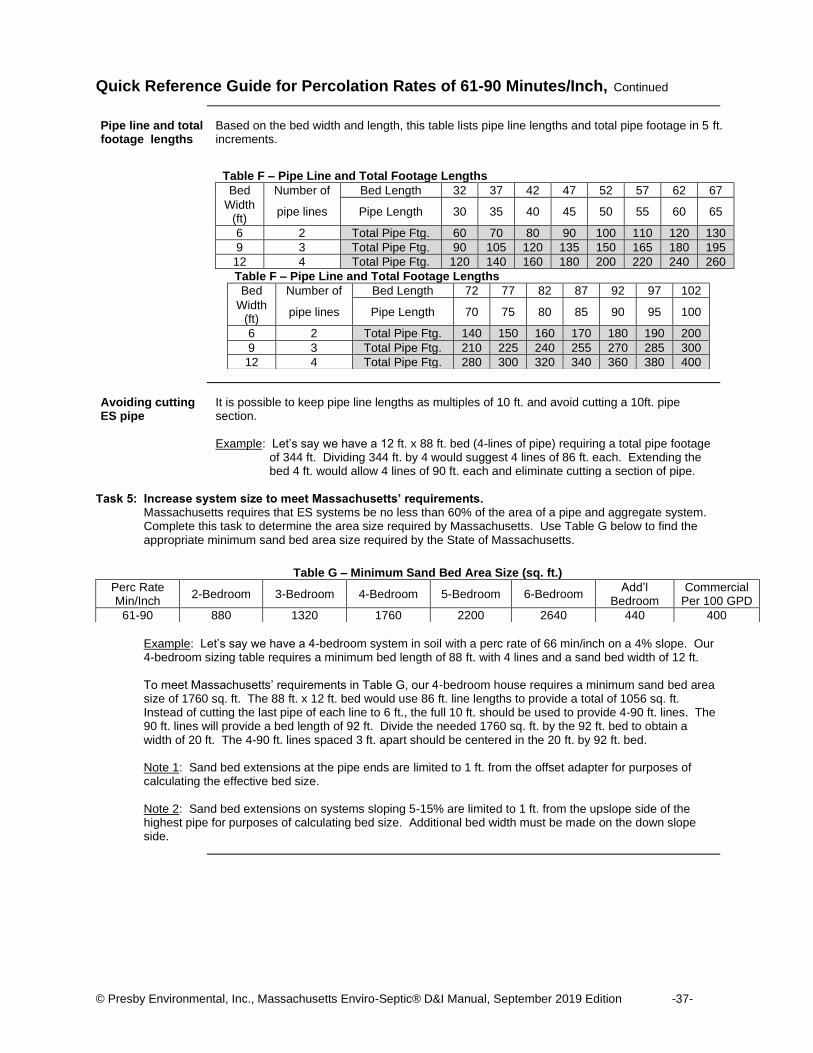
© Presby Environmental, Inc., Massachusetts Enviro-Septic® D&I Manual, September 2019 Edition -37-
Quick Reference Guide for Percolation Rates of 61-90 Minutes/Inch, Continued
Pipe line and total footage lengths
Based on the bed width and length, this table lists pipe line lengths and total pipe footage in 5 ft. increments.
Table F – Pipe Line and Total Footage Lengths
Bed Number of Bed Length 32 37 42 47 52 57 62 67
Width (ft)
pipe lines Pipe Length 30 35 40 45 50 55 60 65
6 2 Total Pipe Ftg. 60 70 80 90 100 110 120 130
9 3 Total Pipe Ftg. 90 105 120 135 150 165 180 195
12 4 Total Pipe Ftg. 120 140 160 180 200 220 240 260
Table F – Pipe Line and Total Footage Lengths
Bed Number of Bed Length 72 77 82 87 92 97 102
Width (ft)
pipe lines Pipe Length 70 75 80 85 90 95 100
6 2 Total Pipe Ftg. 140 150 160 170 180 190 200
9 3 Total Pipe Ftg. 210 225 240 255 270 285 300
12 4 Total Pipe Ftg. 280 300 320 340 360 380 400
Avoiding cutting ES pipe
It is possible to keep pipe line lengths as multiples of 10 ft. and avoid cutting a 10ft. pipe section. Example: Let’s say we have a 12 ft. x 88 ft. bed (4-lines of pipe) requiring a total pipe footage
of 344 ft. Dividing 344 ft. by 4 would suggest 4 lines of 86 ft. each. Extending the bed 4 ft. would allow 4 lines of 90 ft. each and eliminate cutting a section of pipe.
Task 5: Increase system size to meet Massachusetts’ requirements.
Massachusetts requires that ES systems be no less than 60% of the area of a pipe and aggregate system. Complete this task to determine the area size required by Massachusetts. Use Table G below to find the appropriate minimum sand bed area size required by the State of Massachusetts.
Example: Let’s say we have a 4-bedroom system in soil with a perc rate of 66 min/inch on a 4% slope. Our 4-bedroom sizing table requires a minimum bed length of 88 ft. with 4 lines and a sand bed width of 12 ft. To meet Massachusetts’ requirements in Table G, our 4-bedroom house requires a minimum sand bed area size of 1760 sq. ft. The 88 ft. x 12 ft. bed would use 86 ft. line lengths to provide a total of 1056 sq. ft. Instead of cutting the last pipe of each line to 6 ft., the full 10 ft. should be used to provide 4-90 ft. lines. The 90 ft. lines will provide a bed length of 92 ft. Divide the needed 1760 sq. ft. by the 92 ft. bed to obtain a width of 20 ft. The 4-90 ft. lines spaced 3 ft. apart should be centered in the 20 ft. by 92 ft. bed. Note 1: Sand bed extensions at the pipe ends are limited to 1 ft. from the offset adapter for purposes of calculating the effective bed size. Note 2: Sand bed extensions on systems sloping 5-15% are limited to 1 ft. from the upslope side of the highest pipe for purposes of calculating bed size. Additional bed width must be made on the down slope side.
Table G – Minimum Sand Bed Area Size (sq. ft.)
Perc Rate Min/Inch
2-Bedroom 3-Bedroom 4-Bedroom 5-Bedroom 6-Bedroom Add’l
Bedroom Commercial
Per 100 GPD
61-90 880 1320 1760 2200 2640 440 400
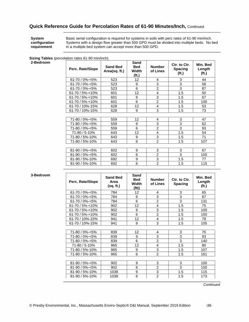
© Presby Environmental, Inc., Massachusetts Enviro-Septic® D&I Manual, September 2019 Edition -38-
Quick Reference Guide for Percolation Rates of 61-90 Minutes/Inch, Continued
System configuration requirement
Basic serial configuration is required for systems in soils with perc rates of 61-90 min/inch. Systems with a design flow greater than 500 GPD must be divided into multiple beds. No bed in a multiple bed system can accept more than 500 GPD.
Sizing Tables (percolation rates 61-90 min/inch) 2-Bedroom
Perc. Rate/Slope Sand Bed
Area(sq. ft.)
Sand Bed
Width (ft.)
Number of Lines
Ctr. to Ctr. Spacing
(ft.)
Min. Bed Length
(ft.)
61-70 / 0%-<5% 523 12 4 3 44
61-70 / 0%-<5% 523 9 3 3 58
61-70 / 0%-<5% 523 6 2 3 87
61-70 / 5%-<10% 601 12 4 1.5 50
61-70 / 5%-<10% 601 9 3 1.5 67
61-70 / 5%-<10% 601 6 2 1.5 100
61-70 / 10%-15% 628 12 4 1.5 53
61-70 / 10%-15% 628 9 3 1.5 73
71-80 / 0%-<5% 559 12 4 3 47
71-80 / 0%-<5% 559 9 3 3 62
71-80 / 0%-<5% 559 6 2 3 93
71-80 / 5-10% 643 12 4 1.5 54
71-80 / 5%-10% 643 9 3 1.5 71
71-80 / 5%-10% 643 6 2 1.5 107
81-90 / 0%-<5% 602 9 3 3 67
81-90 / 0%-<5% 602 6 2 3 100
81-90 / 5%-10% 692 9 3 1.5 77
81-90 / 5%-10% 692 6 2 1.5 115
3-Bedroom
Perc. Rate/Slope Sand Bed
Area (sq. ft.)
Sand Bed
Width (ftt)
Number of Lines
Ctr. to Ctr. Spacing
Min. Bed Length
(ft.)
61-70 / 0%-<5% 784 12 4 3 65
61-70 / 0%-<5% 784 9 3 3 87
61-70 / 0%-<5% 784 6 2 3 131
61-70 / 5%-<10% 902 12 4 1.5 75
61-70 / 5%-<10% 902 9 3 1.5 100
61-70 / 5%-<10% 902 6 2 1.5 150
61-70 / 10%-15% 941 12 4 1.5 78
61-70 / 10%-15% 941 9 3 1.5 105
71-80 / 0%-<5% 839 12 4 3 70
71-80 / 0%-<5% 839 9 3 3 93
71-80 / 0%-<5% 839 6 2 3 140
71-80 / 5-10% 965 12 4 1.5 80
71-80 / 5%-10% 965 9 3 1.5 107
71-80 / 5%-10% 965 6 2 1.5 161
81-90 / 0%-<5% 902 9 3 3 100
81-90 / 0%-<5% 902 6 2 3 150
81-90 / 5%-10% 1038 9 3 1.5 115
81-90 / 5%-10% 1038 6 2 1.5 173
Continued

© Presby Environmental, Inc., Massachusetts Enviro-Septic® D&I Manual, September 2019 Edition -39-
Sizing Tables (percolation rates 61-90 min/inch), Continued
4-Bedroom
Perc. Rate/Slope Sand Bed
Area (sq. ft.)
Sand Bed
Width (ft.)
Number of Lines
Ctr. to Ctr. Spacing
(ft.)
Min. Bed Length
(ft.)
61-70 / 0%-<5% 1046 12 4 3 88
61-70 / 0%-<5% 1046 9 3 3 116
61-70 / 0%-<5% 1046 6 2 3 174
61-70 / 5%-<10% 1203 12 4 1.5 101
61-70 / 5%-<10% 1203 9 3 1.5 134
61-70 / 5%-<10% 1203 6 2 1.5 201
61-70 / 10%-15% 1255 12 4 1.5 105
61-70 / 10%-15% 1255 9 3 1.5 139
71-80 / 0%-<5% 1118 12 4 3 94
71-80 / 0%-<5% 1118 9 3 3 124
71-80 / 0%-<5% 1118 6 2 3 186
71-80 / 5-10% 1286 12 4 1.5 108
71-80 / 5%-10% 1286 9 3 1.5 143
71-80 / 5%-10% 1286 6 2 1.5 214
81-90 / 0%-<5% 1203 9 3 3 134
81-90 / 0%-<5% 1203 6 2 3 201
81-90 / 5%-10% 1383 9 3 1.5 154
81-90 / 5%-10% 1383 6 2 1.5 231
5-Bedroom
Perc. Rate/Slope Sand Bed
Area (sq. ft.)
Sand Bed
Width (ft.)
Number of Lines
Ctr. to Ctr. Spacing
(ft.)
Min. Bed Length
(ft.)
61-70 / 0%-<5% 1307 12 4 3 109
61-70 / 0%-<5% 1307 9 3 3 145
61-70 / 0%-<5% 1307 6 2 3 218
61-70 / 5%-<10% 1503 12 4 1.5 126
61-70 / 5%-<10% 1503 9 3 1.5 167
61-70 / 5%-<10% 1503 6 2 1.5 251
61-70 / 10%-15% 1568 12 4 1.5 131
61-70 / 10%-15% 1568 9 3 1.5 174
71-80 / 0%-<5% 1398 12 4 3 117
71-80 / 0%-<5% 1398 9 3 3 155
71-80 / 0%-<5% 1398 6 2 3 233
71-80 / 5-10% 1608 12 4 1.5 134
71-80 / 5%-10% 1608 9 3 1.5 179
71-80 / 5%-10% 1608 6 2 1.5 268
81-90 / 0%-<5% 1504 9 3 3 168
81-90 / 0%-<5% 1504 6 2 3 251
81-90 / 5%-10% 1730 9 3 1.5 193
81-90 / 5%-10% 1730 6 2 1.5 288
Continued

© Presby Environmental, Inc., Massachusetts Enviro-Septic® D&I Manual, September 2019 Edition -40-
Sizing Tables (percolation rates 61-90 min/inch), Continued
6-Bedroom
Perc. Rate/Slope Sand Bed
Area (sq. ft.)
Sand Bed
Width (ft.)
Number of Lines
Ctr. to Ctr. Spacing
(ft.)
Min. Bed Length
(ft.)
61-70 / 0%-<5% 1569 12 4 3 131
61-70 / 0%-<5% 1569 9 3 3 174
61-70 / 0%-<5% 1569 6 2 3 262
61-70 / 5%-<10% 1804 12 4 1.5 150
61-70 / 5%-<10% 1804 9 3 1.5 200
61-70 / 5%-<10% 1804 6 2 1.5 301
61-70 / 10%-15% 1883 12 4 1.5 157
61-70 / 10%-15% 1883 9 3 1.5 209
71-80 / 0%-<5% 1677 12 4 3 140
71-80 / 0%-<5% 1677 9 3 3 186
71-80 / 0%-<5% 1677 6 2 3 280
71-80 / 5-10% 1929 12 4 1.5 161
71-80 / 5%-10% 1929 9 3 1.5 214
71-80 / 5%-10% 1929 6 2 1.5 322
81-90 / 0%-<5% 1805 9 3 3 201
81-90 / 0%-<5% 1805 6 2 3 301
81-90 / 5%-10% 2076 9 3 1.5 231
81-90 / 5%-10% 2076 6 2 1.5 346
Additional bedroom
Perc. Rate/Slope Sand Bed
Area (sq. ft.)
Sand Bed
Width (ft.)
Number of Lines
Ctr. to Ctr. Spacing
(ft.)
Min. Bed Length
(ft.)
61-70 / 0%-<5% 261 12 4 3 22
61-70 / 0%-<5% 261 9 3 3 29
61-70 / 0%-<5% 261 6 2 3 44
61-70 / 5%-<10% 300 12 4 1.5 25
61-70 / 5%-<10% 300 9 3 1.5 33
61-70 / 5%-<10% 300 6 2 1.5 50
61-70 / 10%-15% 313 12 4 1.5 26
61-70 / 10%-15% 313 9 3 1.5 35
71-80 / 0%-<5% 280 12 4 3 24
71-80 / 0%-<5% 280 9 3 3 31
71-80 / 0%-<5% 280 6 2 3 47
71-80 / 5-10% 322 12 4 1.5 27
71-80 / 5%-10% 322 9 3 1.5 36
71-80 / 5%-10% 322 6 2 1.5 54
81-90 / 0%-<5% 301 9 3 3 34
81-90 / 0%-<5% 301 6 2 3 50
81-90 / 5%-10% 346 9 3 1.5 39
81-90 / 5%-10% 346 6 2 1.5 58
Continued
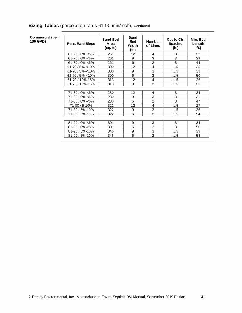
© Presby Environmental, Inc., Massachusetts Enviro-Septic® D&I Manual, September 2019 Edition -41-
Sizing Tables (percolation rates 61-90 min/inch), Continued
Commercial (per 100 GPD)
Perc. Rate/Slope Sand Bed
Area (sq. ft.)
Sand Bed
Width (ft.)
Number of Lines
Ctr. to Ctr. Spacing
(ft.)
Min. Bed Length
(ft.)
61-70 / 0%-<5% 261 12 4 3 22
61-70 / 0%-<5% 261 9 3 3 29
61-70 / 0%-<5% 261 6 2 3 44
61-70 / 5%-<10% 300 12 4 1.5 25
61-70 / 5%-<10% 300 9 3 1.5 33
61-70 / 5%-<10% 300 6 2 1.5 50
61-70 / 10%-15% 313 12 4 1.5 26
61-70 / 10%-15% 313 9 3 1.5 35
71-80 / 0%-<5% 280 12 4 3 24
71-80 / 0%-<5% 280 9 3 3 31
71-80 / 0%-<5% 280 6 2 3 47
71-80 / 5-10% 322 12 4 1.5 27
71-80 / 5%-10% 322 9 3 1.5 36
71-80 / 5%-10% 322 6 2 1.5 54
81-90 / 0%-<5% 301 9 3 3 34
81-90 / 0%-<5% 301 6 2 3 50
81-90 / 5%-10% 346 9 3 1.5 39
81-90 / 5%-10% 346 6 2 1.5 58

© Presby Environmental, Inc., Massachusetts Enviro-Septic® D&I Manual, September 2019 Edition -42-
Level Bed Diagrams (percolation rates 61-90 min/inch)
Introduction Level beds for percolation rates 61-90 min/inch installations are designed in 12, 9, or 6 ft. widths. Here are three diagrams.
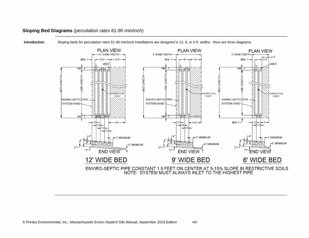
© Presby Environmental, Inc., Massachusetts Enviro-Septic® D&I Manual, September 2019 Edition -43-
Sloping Bed Diagrams (percolation rates 61-90 min/inch)
Introduction Sloping beds for percolation rates 61-90 min/inch installations are designed in 12, 9, or 6 ft. widths. Here are three diagrams.

Appendix A - System Installation Form
For each new or replacement installation, Massachusetts installers of Enviro-Septic® systems must complete and fax, email to [email protected] or mail a copy of this form to the local approving authority and to:
Presby Environmental, Inc. 143 Airport Road Whitefield, NH 03598
Fax: (603) 837-9864
Installer’s Name:
Company Name:
Street Address:
City:
State: Zip:
Property Owner:
Site Street Address:
City:
State: Zip:
System Type (circle one):
General Use or Remedial Use
Design Flow:
Installation Date:
System Startup Date:
Permit Number:
Comments:
This form may also be downloaded from our website at
www.PresbyEnvironmental.com
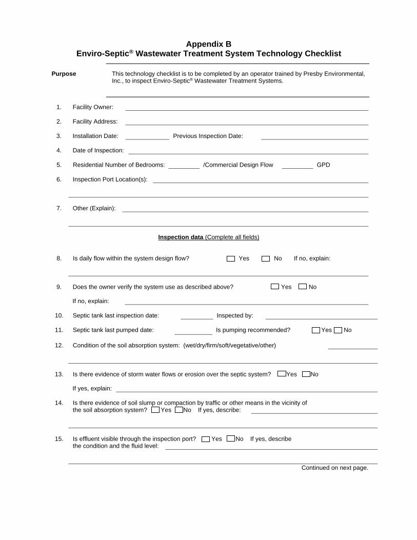
Appendix B Enviro-Septic® Wastewater Treatment System Technology Checklist
Purpose This technology checklist is to be completed by an operator trained by Presby Environmental,
Inc., to inspect Enviro-Septic® Wastewater Treatment Systems.
1. Facility Owner:
2. Facility Address:
3. Installation Date: Previous Inspection Date:
4. Date of Inspection:
5. Residential Number of Bedrooms: /Commercial Design Flow GPD
6. Inspection Port Location(s):
7. Other (Explain):
Inspection data (Complete all fields)
8. Is daily flow within the system design flow? Yes No If no, explain:
9. Does the owner verify the system use as described above? Yes No
If no, explain:
10. Septic tank last inspection date: Inspected by:
11. Septic tank last pumped date: Is pumping recommended? Yes No
12. Condition of the soil absorption system: (wet/dry/firm/soft/vegetative/other)
13. Is there evidence of storm water flows or erosion over the septic system? Yes No
If yes, explain:
14. Is there evidence of soil slump or compaction by traffic or other means in the vicinity of
the soil absorption system? Yes No If yes, describe:
15. Is effluent visible through the inspection port? Yes No If yes, describe
the condition and the fluid level:
Continued on next page.
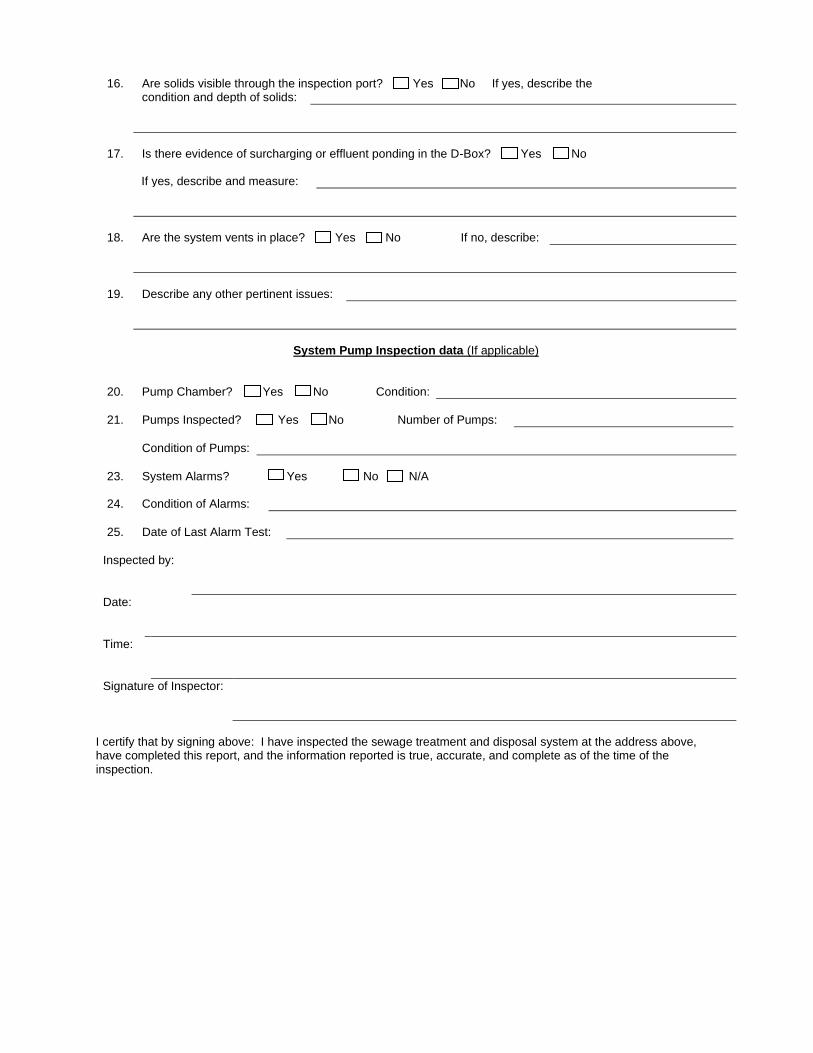
16. Are solids visible through the inspection port? Yes No If yes, describe the condition and depth of solids:
17. Is there evidence of surcharging or effluent ponding in the D-Box? Yes No
If yes, describe and measure:
18. Are the system vents in place? Yes No If no, describe:
19. Describe any other pertinent issues:
System Pump Inspection data (If applicable)
20. Pump Chamber? Yes No Condition:
21. Pumps Inspected? Yes No Number of Pumps:
Condition of Pumps:
23. System Alarms? Yes No N/A
24. Condition of Alarms:
25. Date of Last Alarm Test:
Inspected by:
Date:
Time:
Signature of Inspector:
I certify that by signing above: I have inspected the sewage treatment and disposal system at the address above, have completed this report, and the information reported is true, accurate, and complete as of the time of the inspection.

Appendix C Enviro-Septic® Wastewater Treatment System Operating Manual
Introduction ES wastewater treatment systems are virtually maintenance free. However, an awareness of system
abuse and simple easy maintenance will guarantee system longevity.
System abuse conditions
The following conditions constitute system abuse.
• Liquid in high volume (excessive number of occupants, leaking fixtures, water beds, or whirlpool tubs, hot tubs, or water softeners if not specified in system design)
• Solids in high volume (excessive number of occupants, paper products, personal hygiene products, or garbage disposals or water softeners if not specified in system design)
• Antibiotic medicines in high concentrations
• Cleaning products in high concentrations
• Fertilizers or other caustic chemicals in any amount
• Petroleum products in any amount
System maintenance
These simple procedures will guarantee system longevity.
• Inspect the septic tank at least once every two years under normal usage. Have the tank emptied when surface scum and bottom sludge occupy one-fourth or more of tank capacity.
• After pumping, inspect the septic tank for integrity to ensure than no groundwater flow is entering septic tank. Also check the integrity of the tank inlet and outlet baffles.
• Inspect the system for proper venting through either the roof or distribution box vent.