Embed Size (px)
Citation preview

S22The production platformfor your individual grinding solution.

S22
2
Advantages
S22 – Dimensions• Grinding length max. 800 mm• Center height 175/225 mm• Diameter of grinding wheel up to 610 mm
Hardware• Granitan® mineral-casting S103 machine
base• Cross slide X: pretensioned hydrostatics
with linear motor or anti-friction guideways with ball-screw.
• Longitudinal slide Z: hydrostatic with linear motor or guideway with patented surface structure and ball-screw linear drive
• C axis for the workhead• Application-specific workhead concepts• Additional NC axis for profiling the grinding
wheel• Full enclosure with movable front panels for
optimal accessibility
• Integrated loading unit or loading cell for loading and unloading from left, right or above
• Large range of accessories
Software• Easy programming with StuderWIN on
Fanuc 310i -A• StuderGRIND programming software
to create grinding and dressing programs • Standardized interfaces for loading and
peripheral devices
3
1
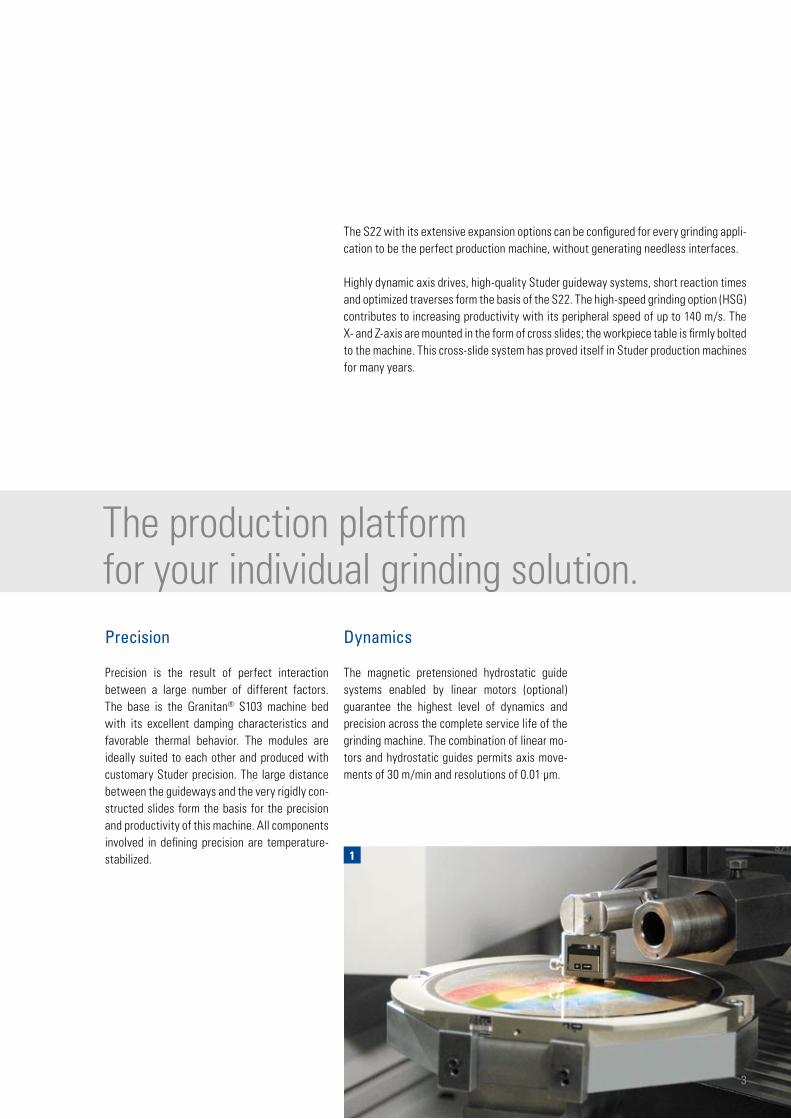
The S22 with its extensive expansion options can be configured for every grinding appli-cation to be the perfect production machine, without generating needless interfaces.
Highly dynamic axis drives, high-quality Studer guideway systems, short reaction times and optimized traverses form the basis of the S22. The high-speed grinding option (HSG) contributes to increasing productivity with its peripheral speed of up to 140 m/s. The X- and Z-axis are mounted in the form of cross slides; the workpiece table is firmly bolted to the machine. This cross-slide system has proved itself in Studer production machines for many years.
The production platform for your individual grinding solution. Precision
Precision is the result of perfect interaction between a large number of different factors. The base is the Granitan® S103 machine bed with its excellent damping characteristics and favorable thermal behavior. The modules are ideally suited to each other and produced with customary Studer precision. The large distance between the guideways and the very rigidly con-structed slides form the basis for the precision and productivity of this machine. All components involved in defining precision are temperature-stabilized.
Dynamics
The magnetic pretensioned hydrostatic guide systems enabled by linear motors (optional) guarantee the highest level of dynamics and precision across the complete service life of the grinding machine. The combination of linear mo-tors and hydrostatic guides permits axis move-ments of 30 m/min and resolutions of 0.01 µm.

1 2
3
Mineral casting machine bed
Machine base produced in Granitan®
Frequency
Ampl
itude
4
- Vibration-damping
- Thermal stability
- Non-wearing
Granitan® mineral-casting S103 machine base
The material structure developed by Studer, which has proved its superb efficiency over many years, is produced in the company's own plant using the most modern industrial techniques.• The excellent cushioning behavior of the ma-
chine base ensures outstanding surface qual-ity of the ground workpieces. The service life of the grinding wheel is also increased, lead-ing to reduced downtimes.
• Temporary temperature fluctuations are ex-tensively compensated for by the favorable thermal behavior of Granitan®, resulting in high dimensional accuracy at all times. This provides high stability throughout the day.
• The V and flat guideways for the longitudinal and cross slides are moulded directly into the machine base and are provided with a non-abrasive Granitan® S200 slideway coating. The guideways offer the highest possible ac-curacy through the entire speed range with high load capacity and cushioning levels. Thanks to the robust and maintenance-free design, these excellent guideway character-istics are more or less completely retained. The non-magnetic machine bed is particularly suitable for linear motors.

54
5
1 | Guideways with patented surface structure
2 | Vibration behavior of gray cast iron and Granitan® S103
3 | Machine base with Z guideways
4 | Z - axis with ball-screw
5 | Z - axis with linear motor
Cross-slides
The X- and Z-axis are mounted in the form of cross slides; the workpiece table is firmly bolt-ed to the machine. This cross-slide system has proved itself in STUDER production circular grin-ding machines for years.
The generous guide spacings provide the basis for a stable and robust design of cross slide and wheelhead.
Two different axis drive systems are available.Standard:X-axisAnti-friction guideways with ball-screw.Z-axisGuideway with patented surface structure and ball-screw. Economic versions that meet high quality requirements. The surface structure pre-vents the slides from swimming up and also elim-inates the stick-slip effect, which is otherwise noted in conventional guideways. The linear measuring system is mounted on the slide and is therefore not influenced by variations in tem-perature. The thermal expansion of the ball-type spindles is compensated for by direct reading on the glass scale.
Optional:X-axisPretensioned hydrostatics with linear motors. Z-axisPretensioned hydrostatics with linear motors. The pretensioned hydrostatics are applied when the highest level of precision is required. Thanks to the measuring system resolution of 0.01 µm, the tenth part µ can be securely mastered. The non-contact axis system guarantees exceptional precision throughout the whole service life of the machine.
- High geometric traverse precision
- Effective covering of the guideways

1
2
6
Wheelhead
The S22 platform has many different wheelhead variants. The machine can be optimally config-ured for any application. A swiveling with axis swiveling angle -3°/+9° for the right wheel and -9°/+3° for the left wheel, is available for the 0° machine model. A turret wheelhead with wheel left/left resp. right/left rounds off the program.
- Configurable according to client's requirements
- High performance
- Cutting speed up to 50 m /s (HSG 140 m / s)

3
4
5
7
Workhead
With its high-precision roller bearings the work-head is used for grinding between fixed centers and for live spindle grinding. The powerful work-head spindle has a MK4 or ISO50 fitting taper. The airlift simplifies adjustment when setting up or resetting the workhead. The fine adjustment enables taper corrections in the µm-range during live spindle grinding.
C-axis for form and thread grinding
Complete machining also entails form and thread grinding operations to an ever increasing extent. These processes are made possible by the posi-tion and speed-controlled C-axis. The standard C-axis with measuring system on the drive motor is suitable for thread grinding. To ensure the high-est shape accuracy a direct measuring system is mounted on the workhead spindle (high-pre-cision C-axis). Acceleration and grinding forces are absorbed without difficulty through the high dynamic rigidity of the axis drives.
1 | Examples for wheelhead configurations
2 | Wheelhead
3 | Fine adjustment for taper corrections
4 | Chuck workhead
5 | Thread grinding
- High roundness accuracy
- Low-maintenance
1
3
2
8
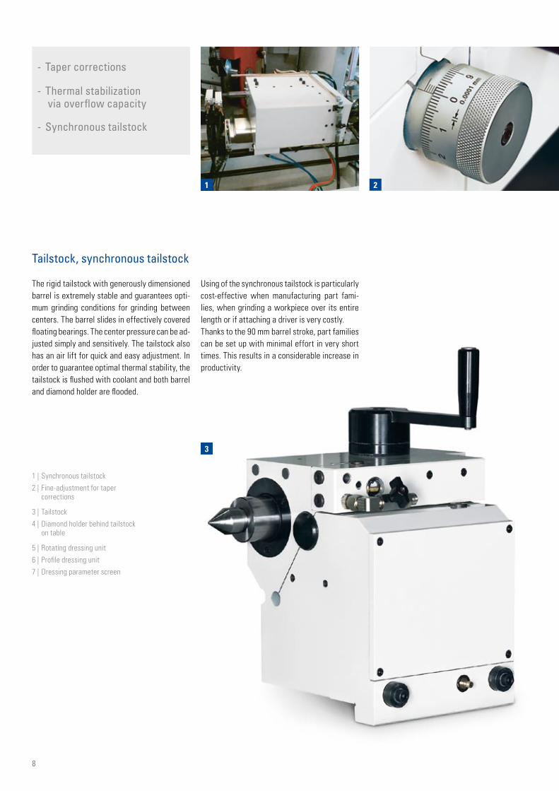
- Taper corrections
- Thermal stabilization via overflow capacity
- Synchronous tailstock
1 | Synchronous tailstock
2 | Fine-adjustment for taper corrections
3 | Tailstock
4 | Diamond holder behind tailstock on table
5 | Rotating dressing unit
6 | Profile dressing unit
7 | Dressing parameter screen
Tailstock, synchronous tailstock
The rigid tailstock with generously dimensioned barrel is extremely stable and guarantees opti-mum grinding conditions for grinding between centers. The barrel slides in effectively covered floating bearings. The center pressure can be ad-justed simply and sensitively. The tailstock also has an air lift for quick and easy adjustment. In order to guarantee optimal thermal stability, the tailstock is flushed with coolant and both barrel and diamond holder are flooded.
Using of the synchronous tailstock is particularly cost-effective when manufacturing part fami-lies, when grinding a workpiece over its entire length or if attaching a driver is very costly.Thanks to the 90 mm barrel stroke, part families can be set up with minimal effort in very short times. This results in a considerable increase in productivity.

4 5 6
7
9
Dressing
A sharp grinding wheel is essential for cost-ef-fective, high-quality grinding. In order to create a flexible and optimal dressing process that co-ordinates with the properties of the workpiece, tool and materials, Studer provides a large selec-tion of dressing units. The grinding wheel profile and dressing parameters are easily defined via macros. Another Studer speciality is the grind-ing wheel reference points (T-numbers). This enables programming with normal dimensions, which considerably facilitates the development of grinding programs.
A software package is available to fine tune the dressing process and includes additional dress-ing functions.

2
1
10
Operation and programming
The S22 is equipped with a Fanuc control sys-tem, series 310i-A. The clear and ergonomic ar-rangement of the control elements guarantees efficient operation.
The control cabinet can be positioned left, right or behind the machine, in accordance with the client's requirements. The power and control compartments are separated. The layout of the elements complies with the relevant safety norms and is EMC-tested.
- PCU manual control unit
- EMC-tested control cabinet
- Ergonomically arranged controls

4
5
3
11
1 | Manual control unit
2 | Machine control
3 | StuderWin
4 | Workpiece programming
5 | Correction
- Latest software technology
- Pictogramming
- Programming software StuderGRIND
StuderWIN
StuderWIN as user interface and the software modules of StuderGRIND create a stable pro-gramming environment and contribute to the ef-ficiency of the machine. A PC is integrated into the CNC control. The possibility of fully integrat-ing the in-process gauging and sensor technol-ogy for process monitoring as well as contact de-tection and automatic balancing systems in the Windows control enable standardised program-ming of the different systems. The software for an internal loading system is also integrated in the control. The drive elements are optimally adapted to the control.
The sophisticated mechanical engineering con-cept of the S22 is completed by a grinding soft-ware program developed in-house by Studer and continuously further optimized in collaboration with customers. This software offers:• Pictogramming: The operator strings the indi-
vidual grinding cycles together – the control unit generates the ISO code.
• Quick-Set: The software for grinding wheel alignment reduces changeover times by up to 90 %.
• Microfunctions: Free programming of grinding and dressing process sequences for optimiza-tion of the grinding process.
• StuderGRIND: Programming software for special applications such as form and thread grinding and profiling the grinding wheel for complex workpiece forms; the program is cre-ated on the PC and transferred directly to the machine control unit.
1
12
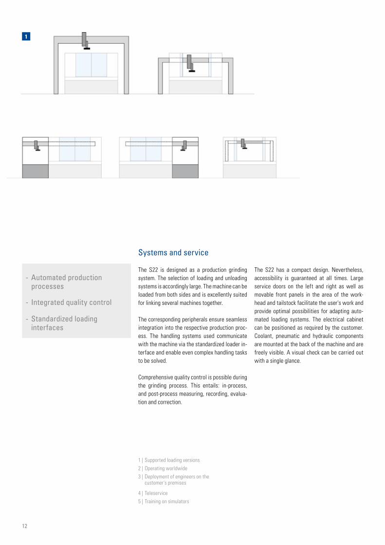
Systems and service
The S22 is designed as a production grinding system. The selection of loading and unloading systems is accordingly large. The machine can be loaded from both sides and is excellently suited for linking several machines together.
The corresponding peripherals ensure seamless integration into the respective production proc-ess. The handling systems used communicate with the machine via the standardized loader in-terface and enable even complex handling tasks to be solved.
Comprehensive quality control is possible during the grinding process. This entails: in-process, and post-process measuring, recording, evalua-tion and correction.
- Automated production processes
- Integrated quality control
- Standardized loading interfaces
The S22 has a compact design. Nevertheless, accessibility is guaranteed at all times. Large service doors on the left and right as well as movable front panels in the area of the work-head and tailstock facilitate the user's work and provide optimal possibilities for adapting auto-mated loading systems. The electrical cabinet can be positioned as required by the customer. Coolant, pneumatic and hydraulic components are mounted at the back of the machine and are freely visible. A visual check can be carried out with a single glance.
1 | Supported loading versions
2 | Operating worldwide
3 | Deployment of engineers on the customer's premises
4 | Teleservice
5 | Training on simulators

2
3 4 5
13
Accessories and services
There is an extensive range of accessories avail-able for all Studer cylindrical grinding machines. This includes centers, dressing tools, grinding wheels, clamping devices, internal grinding spin-dles and in-process gauging devices.
The Studer Training Department organizes cours-es for hundreds of customers every year special-izing in programming and machine use - a sound basis for optimum use of your Studer machines.
Maintenance courses are tailored to the respec-tive requirements of the maintenance depart-ments. On request, they can also take place on
the customer's premises. Studer specialists col-laborate in grinding problems, in order to achieve the optimal solution.
After-sales services speak the user's language and operate at an international level, meaning that the service technicians can be at the client's site quickly. With a well planned range of serv-ices offered, they help the user get optimum use of his machine. Spare parts are available for at least a further ten years after discontinuation of a series of machines.
- Commissioning
- Training
- Production support
- Warranty extension
- Helpline
- Repair
- Spare parts
- Remote service
- Inspection
- Maintenance
- Overhaul
14
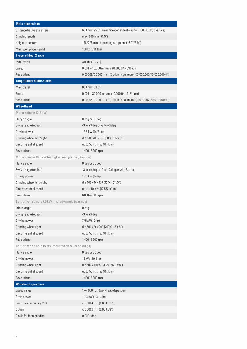
Main dimensions
Distance between centers 650 mm (25.6”) (machine-dependent – up to 1 100 (43.3”) possible)
Grinding length max. 800 mm (31.5”)
Height of centers 175/225 mm (depending on options) (6.9”/8.9”)
Max. workpiece weight 150 kg (330 lbs)
Cross-slides: X-axis
Max. travel 310 mm (12.2”)
Speed: 0,001 – 15,000 mm/min (0.000.04 – 590 ipm)
Resolution: 0.00005/0,00001 mm (Option linear motor) (0.000.002”/0.000.000.4”)
Longitudinal slide: Z-axis
Max. travel 850 mm (33.5”)
Speed: 0,001 – 30,000 mm/min (0.000.04 – 1181 ipm)
Resolution: 0.00005/0,00001 mm (Option linear motor) (0.000.002”/0.000.000.4”)
Wheelhead
Motor spindle 12.5 kW
Plunge angle 0 deg or 30 deg
Swivel angle (option) -3 to +9 deg or -9 to +3 deg
Driving power 12.5 kW (16.7 hp)
Grinding wheel left/right dia. 500 x 80 x 203 (20”x 3.15”x 8”)
Circumferential speed up to 50 m/s (9840 sfpm)
Revolutions 1 400–3 200 rpm
Motor spindle 10.5 kW for high-speed grinding (option)
Plunge angle 0 deg or 30 deg
Swivel angle (option) -3 to +9 deg or -9 to +3 deg or with B-axis
Driving power 10.5 kW (14 hp)
Grinding wheel left/right dia 400 x 40 x 127 (16”x 1.5”x 5”)
Circumferential speed up to 140 m/s (17 552 sfpm)
Revolutions 6 000–9 000 rpm
Belt-driven spindle 7.5 kW (hydrodynamic bearings)
Infeed angle 0 deg
Swivel angle (option) -3 to +9 deg
Driving power 7.5 kW (10 hp)
Grinding wheel right dia 500 x 80 x 203 (20”x 3.15”x 8”)
Circumferential speed up to 50 m/s (9840 sfpm)
Revolutions 1 400–3 200 rpm
Belt-driven spindle 15 kW (mounted on roller bearings)
Plunge angle 0 deg or 30 deg
Driving power 15 kW (20.5 hp)
Grinding wheel right dia 600 x 160 x 203 (24”x 6.3”x 8”)
Circumferential speed up to 50 m/s (9840 sfpm)
Revolutions 1 400–3 200 rpm
Workhead spectrum
Speed range 1 – 4 000 rpm (workhead-dependent)
Drive power 1 – 3 kW (1.3 – 4 hp)
Roundness accuracy MT4 < 0,0004 mm (0.000.016”)
Option < 0,0002 mm (0.000.08”)
C axis for form grinding 0,0001 deg

4600
2150
3600
3400
3360
240020
1200
1000
200
2600
39503550
2950
2150
1000
2532
213020151768
477
450
2400
3400
4550
2400
621
15
The information given is based on the technical levels of our machine at the time of this brochure going to print. We reserve the right to further develop our machines technically and make design modifications. This means that the dimensions, weights, colors, etc. of the machines supplied can differ. The diverse application possibilities of our machines depend on the technical equipment specifically requested by our customers. The equipment specifically agreed with the customer is therefore exclusively definitive for the equipping of the machines, and not any general data, information or illustrations.
Tailstock
Fitting taper MT3 (MT4)
Travel of barrel 35 mm (1.37”) [60 mm (2.3”)]
Barrel diameter 50 mm (1.97”)
Fine adjustment ± 40 µm (0.0016”)
Synchronous tailstock
Fitting taper MT3 (MT4)
Travel of barrel 90 mm (3.54”)
Barrel diameter 50 mm (1.97”)
Drive power 1,6 kW (2.2 hp)
Fine adjustment ± 40 µm (0.0016”)
Tailstock for fine grinding
Fitting taper MT3 (MT4)
Travel of barrel 35 mm (1.37”) [60 mm (2.3”)]
Barrel diameter 50 mm (1.97”)
Fine adjustment ± 80 µm (0.0031”)
Control unit
Fanuc 310i-A
Connected loads
Total connected loads Max. 47 kVA
Air pressure 5,5 bar (80 psi)
Total weight 8500 kg (18 700 lbs)

06.2
008 /
Prin
ted
in S
witz
erla
nd
ISO 9001VDA6.4certified
Fritz Studer AGCH-3602 ThunTelephone +41-33-439 11 11 · Telefax +41-33-439 11 12www.studer.com