Embed Size (px)
Citation preview


The Project Gutenberg EBook ofThings To Make, by ArchibaldWilliams
This eBook is for the use of anyoneanywhere at no cost and with almost norestrictions whatsoever. You may copyit, give it away or re-use it under theterms of the Project Gutenberg Licenseincluded with this eBook or online atwww.gutenberg.net
Title: Things To Make
Author: Archibald Williams
Release Date: January 11, 2005 [EBook#14664]

Language: English
*** START OF THIS PROJECTGUTENBERG EBOOK THINGS TOMAKE ***
Produced by Don Kostuch
Transcriber's Note:
If the pdf version of the book is viewedusing facing pages with even numbered

pages on the left, you will see a closeapproximation of the original book.
Notations of the form "(1,650) 2"appear at the bottom of some pages;they are probably printer's referencesfor assembling to book.
The text only version is of limited usebecause of the many figures used. Irecommend the pdf or rtf versions.
Some of the projects should beapproached with care since theyinvolve corrosive or explosivechemicals, electricity and steamboilers.
Do not use lead solder, particularly on
cooking utensils.
Whether you simply want to travelback into the mind of a young boy atthe beginning of the twentieth century,or want to try your hand at someinteresting projects in carpentry,machinery, kites and many other areas,have fun.
The following are definitions ofunusual (to me) terms used frequentlyin the text.
Terms
Batten - Narrow strip of wood.
Bevel (Bevelling) - A cut that is not aright angle.
Bradawl - Awl with a beveled tip tomake holes in wood for brads orscrews.
Chamfer - Cut off the edge or corner;bevel.
Boss - Enlarged part of a shaft whereanother shaft is coupled or a wheel orgear is keyed.
Broach - To shape a hole with a taperedtool.
Carbide - Calcium carbide, used toproduce acetylene (C2H2) gas for
lighting and welding.
Compo - "Composition", like plastic.
Creosote - An oily liquid containingphenols and creosols, obtained fromcoal tar. Used as a wood preservativeand disinfectant. Can cause severeneurological disturbances if inhaled.
Deal - A fir or pine board of standarddimensions
Fish-plate - A plate bolted to the sidesof two abutting railroad tracks.
Fretworking - Ornamental design, oftenin relief.
Gasholder Gasometer - Storagecontainer for fuel gas, especially alarge, telescoping, cylindrical tank.
Gland - The outer sleeve of a stuffingbox that prevents leakage past amoving machine part.
Glass paper - Paper faced withpulverized glass, like sandpaper.
Gudgeon - A metal pivot or journal atthe end of a shaft or an axle, aroundwhich a wheel or other device turns.
Joiner - A cabinetmaker.
Linoleum - A floor covering made insheets by pressing heated linseed oil,
rosin, powdered cork, and pigmentsonto a burlap or canvas backing.
Lissom - Easily bent; supple
Longitudinal - Relating to length.
Mortice - Cavity in a piece of wood orother material, prepared to receive atenon and form a joint.
Panel saw - Handsaw with fine teeth.
Pinion - Gear with a small number ofteeth designed to mesh with a largergear.
Plinth - Architectural support or base.
Rasp - Coarse file with sharp, raised,pointed projections.
Sleeper - Railroad crosstie.
Spanner - Wrench
Spirit Lamp - Alcohol lamp; seeexample on page 188.
Spirit - Alcohol
Strake - Ridge of thick planking on theside of a wooden ship.
Strut - Any part designed to hold thingsapart or resist compressive stress;
Tap - Cut screw threads

Tenon - Projection on the end of apiece of wood shaped for insertion intoa mortise to make a joint.
Tenon saw - Saw with a thin blade forcutting tenons.
Tinning - Coating with soft solder.
Turner - Person who operates a lathe orsimilar device.
Tyre - Tire
Vestas - Matches; Vestai is the Romangoddess of the hearth, worshiped in atemple containing the sacred firetended by the vestal virgins.
Currency Conversion
Prices are quoted in old Englishcurrency, pounds, shillings, pence.
"12s. 6d." is read as "12 Shillings and 6Pence."
Pence/pennyShilling—12 pence.Crown—5 shillings.Pound—20 shillings.Guinea—21 shillings.
The approximate value of 1900 pricesin 2002 is:1900 Unit Value in 2002 Currency English Pound US DollarsPence .26 .48
Shilling 3.10 5.80Crown 15.50 29.00Pound 62.00 116.00
[End Transcriber's note.]
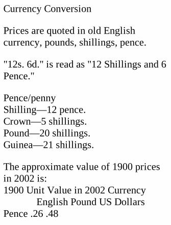
[Illustration: Large model locomotive]
Photo: Daily Mirror. Large modellocomotive built for one of the royalprinces of Siam by Messrs. Bassett-Lowke, Limited. It is one-quarter thesize of a modern express engine;weighs two tons, with tender; is fifteenfeet long; will pull seventy persons;and has a highest speed of about thirtymiles an hour.

THINGS TO MAKE BYARCHIBALD WILLIAMSAUTHOR OF "VICTORIESOF THE ENGINEER,""HOW IT WORKS,""HOW IT IS MADE,"ETC., ETC. THOMASNELSON AND SONS, LTD.LONDON, EDINBURGH,AND NEW YORK
PREFACE.

The making for oneself of toys andother objects of a more or less usefulcharacter has certain advantages overbuying them. In the case of the moreelaborate and costly articles, it mayenable one to possess things whichotherwise would be unobtainable.Secondly, a home-made article maygive a satisfaction more lasting than isconferred by a bought one, though itmay be less beautiful to look upon.Thirdly, the mere making should be apleasure, and must be an education initself.
To encourage readers to "use theirhands" the following chapters havebeen written. The subjects chosen
provide ample scope for the exercise ofingenuity and patience; but in makingmy selection I have kept before me thefact that a well-equipped workshopfalls to the lot of but a few of the boyswho are anxious to develop intoamateur craftsmen. Therefore, whilethe easiest tasks set herein are veryeasy, the most difficult will not befound to demand a very high degree ofskill, or more than a very moderateoutlay on tools. I may say here that Ihave been over the ground myself tofind out its difficulties for my readers,and that I made an engine similar tothat described in Chapter XV (the mostelaborate mechanism included in thebook) with very simple tools. Some of
the items which I had on my originallist were abandoned, because theypresupposed the possession ofcomparatively expensive machines.
My selection has also been guided bythe desire to cater for different tastes.In some cases the actual manufactureof the thing described may be regardedas the most instructive and valuableelement, and may appeal most forciblyto the "handy" boy; in others—theHarmonograph provides a goodinstance—the interest centres round theexperiments made possible by theconstruction of a simple piece ofapparatus; in some the utility of thearticle manufactured is its chief

recommendation.
I feel certain that anyone who followsout the pages of this volume with handas well as with eye, will have littlereason to regret the time so spent. Thethings made may in course of time beput aside and forgotten, but the manualskill acquired will remain. Nowadaysone can buy almost anything ready-made, or get it made without difficulty;yet he who is able to make things forhimself will always have an advantageover the person to whom the use oftools is an unprobed mystery.

CONTENTS.
I. SAWING TRESTLE II. A JOINER'SBENCH III. A HANDY BOOKSTAND IV. AHOUSE LADDER V. A DEVELOPINGSINK VI. A POULTRY HOUSE AND RUNVII. A SHED FOR YOUR BICYCLE VIII.A TARGET APPARATUS FOR RIFLESHOOTING IX. CABINET-MAKING X.TELEGRAPHIC APPARATUS XI. ARECIPROCATING ELECTRIC MOTORXII. AN ELECTRIC ALARM CLOCK XIII.A MODEL ELECTRIC RAILWAY XIV. ASIMPLE RECIPROCATING ENGINE XV.A HORIZONTAL SLIDE-VALVE ENGINEXVI. MODEL STEAM TURBINES XVII.STEAM TOPS XVIII. MODEL BOILERSXIX. QUICK-BOILING KETTLES XX. AHOT-AIR ENGINE XXI. A WATERMOTOR XXII. MODEL PUMPS XXIII.

KITES XXIV. PAPER GLIDERS XXV. ASELF-LAUNCHING MODELAEROPLANE XXVI. APPARATUS FORSIMPLE SCIENTIFIC EXPERIMENTSXXVII. A RAIN GAUGE XXVIII. WINDVANES WITH DIALS XXIX. ASTRENGTH-TESTING MACHINE XXX.LUNG-TESTING APPARATUS XXXI.HOME-MADE HARMONOGRAPHSXXXII. A SELF-SUPPLYING MATCHBOXXXXIII. A WOODEN WORKBOX XXXIV.WRESTLING PUPPETS XXXV. DOUBLEBELLOWS XXXVI. A HOME-MADEPANTOGRAPH XXXVII. A SILHOUETTEDRAWING MACHINE XXXVIII. ASIGNALLING LAMP XXXIX. AMINIATURE GASWORKS
THINGS TO MAKE.
I. A SAWING TRESTLE
A strong and stable sawing trestle isone of the most important accessoriesof the carpenter's shop, whetheramateur or professional. The saw isconstantly being used, and for it to doits work accurately the material mustbe properly supported, so that it cannotsway or shift. Anybody who has beenin the habit of using a wobbly chair orbox to saw on will be surprised to findhow much more easily wood can be cut

when resting on a trestle like thatillustrated by Figs. 1 to 3.
The top, a, of the trestle is 29 incheslong, 4 inches wide, and 2 inches thick.At one end it has a deep nick, to servemuch the same purpose as the notchedboard used in fretworking; also to holdon edge such things as doors whiletheir edges are planed up. Pushed backagainst the wall the trestle is then "asgood as a boy."
[Illustration: Fig I.—Leg of sawingtrestle (left). Trestle seen from above(right).]
The four legs are made of 2 by 2 inchstuff. To start with, the pieces should

be 24 inches long, to allow for thewaste of cutting on the angle.
Cutting the Notches.—Make fourmarks 7 inches from the four corners ofthe top, set your bevel to an angle of 70degrees (or cut an angle out of a cardwith the help of a protractor), and lay aleg against each mark in turn, the endprojecting an inch or so above the top.Move the leg about till it makes theproper angle at the mark, and draw apencil line down each side of the leg asclose up as possible. Since the legsmay vary slightly in size, use each onceonly for marking, and number it andthe place to which it belongs.

Lines must now be drawn along theupper and under sides of the top,parallel to and 3/4-inch from the edge,to complete the marking out of thenotches.
Cut just inside the side marks with afine tenon saw, and remove the woodbetween the cuts back to the top andbottom marks with a broad, sharpchisel, making the surface of the cut astrue and flat as you can. Then "offer"the leg that belongs to the cut, its endprojecting an inch or so. If it won'tenter, bevel off the sides of the cut veryslightly till it will. A good driving fit iswhat one should aim at. While the legis in place, draw your pencil in the
angles which it makes with the topabove and below, to obtain the linesAB, CD (Fig. 2, a).
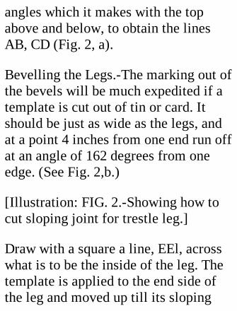
Bevelling the Legs.-The marking out ofthe bevels will be much expedited if atemplate is cut out of tin or card. Itshould be just as wide as the legs, andat a point 4 inches from one end run offat an angle of 162 degrees from oneedge. (See Fig. 2,b.)
[Illustration: FIG. 2.-Showing how tocut sloping joint for trestle leg.]
Draw with a square a line, EEl, acrosswhat is to be the inside of the leg. Thetemplate is applied to the end side ofthe leg and moved up till its sloping
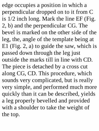
edge occupies a position in which aperpendicular dropped on to it from Cis 1/2 inch long. Mark the line EF (Fig.2, b) and the perpendicular CG. Thebevel is marked on the other side of theleg, the, angle of the template being atE1 (Fig. 2, a) to guide the saw, which ispassed down through the leg justoutside the marks till in line with CD.The piece is detached by a cross cutalong CG, CD. This procedure, whichsounds very complicated, but is reallyvery simple, and performed much morequickly than it can be described, yieldsa leg properly bevelled and providedwith a shoulder to take the weight ofthe top.
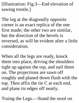
[Illustration: Fig.3—End elevation ofsawing trestle.]
The leg at the diagonally oppositecorner is an exact replica of the onefirst made; the other two are similar,but the direction of the bevels isreversed, as will be evident after a littleconsideration.
When all the legs are ready, knockthem into place, driving the shoulderstight up against the top, and nail themon. The projections are sawn offroughly and planed down flush with thetop. Then affix the tie C at each end,and plane its edges off neatly.
Truing the Legs.—Stand the stool on
end, top flat against the wall. Measureoff a 20-inch perpendicular from thewall to the outside corner of each of thetwo upper legs. (Fig. 3.) Lay astraightedge from mark to mark, anddraw lines across the legs. Reverse thetrestle, and do the same with the legs atthe other end. Then turn the trestle onits side, and draw lines on the otheroutside faces of the legs, using thelines already made as guides. If theoperation has been carried throughaccurately, all eight lines will be in aplane parallel to the top. Cut off theends of the legs below the lines, andthe trestle is finished.

II. A JOINER'S BENCH.
After finishing his sawing trestle thereader may be willing to undertake alarger job, the manufacture of a joiner'sbench—if he does not already possess agood article—heavy and rigid enoughto stand firm under plane and hammer.
For the general design and detailedmeasurements he is referred to Figs. 4and 5, in which the dimensions of eachpart are figured clearly. The length of 5feet, width of 2 feet (exclusive of theback E), and height of 2 feet 7-1/2inches will be found a good average. Ifthe legs prove a bit long for somereaders, it is a simple matter to lay a
plank beside the bench to raise the(human) feet an inch or two.
In order to give rigidity, the strutsS1S2 of the trestles at the end and thebraces DD on the front are "halved"where they overlap the legs and frontso as to offer the resistance of a"shoulder" to any thrust.
[Illustration: Fig. 4.—Front elevationof Joiner's bench]
Materials.—The cost of these will be,approximately: wood, 12s. 6d.; [12Shillings. 6 Pence] bench screw, 1s.6d.; nails and screws, 1s.; or 15s. in all.It is advisable to show the timbermerchant the specifications, so that he
may cut up the stuff mosteconomically.
If the wood is mill-planed beforedelivery a lot of trouble will be saved,as no further finish will be required,except perhaps at the top corners. Inpassing, one should remark that theboards used should be of the widthsand lengths given; while as regardsthickness the figures must be taken asnominal, as in practice the saw cut isincluded. Thus a 1-inch board would,when planed, be only 7/8 to 15/16 inchthick, unless the actual size isspecified, in which case somethingextra might be charged.
Construction.
The Trestles.—These should be madefirst. Begin by getting all the legs ofexactly the same length, and square topand bottom. Then cut off two 22-inchlengths of the 6 by 1 inch wood,squaring the ends carefully. Two of thelegs are laid on the floor, one endagainst the wall or a batten nailed tothe floor and arranged parallel to oneanother, as gauged by the piece C,which is nailed on perfectly square toboth, and with its top edge exactlyflush with the ends of the legs.
Next take the 3 by 1 inch wood for thestruts, and cut off a piece 32 inches
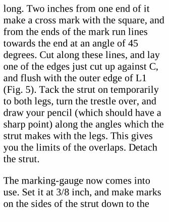
long. Two inches from one end of itmake a cross mark with the square, andfrom the ends of the mark run linestowards the end at an angle of 45degrees. Cut along these lines, and layone of the edges just cut up against C,and flush with the outer edge of L1(Fig. 5). Tack the strut on temporarilyto both legs, turn the trestle over, anddraw your pencil (which should have asharp point) along the angles which thestrut makes with the legs. This givesyou the limits of the overlaps. Detachthe strut.
The marking-gauge now comes intouse. Set it at 3/8 inch, and make markson the sides of the strut down to the
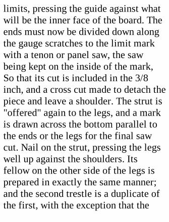
limits, pressing the guide against whatwill be the inner face of the board. Theends must now be divided down alongthe gauge scratches to the limit markwith a tenon or panel saw, the sawbeing kept on the inside of the mark,So that its cut is included in the 3/8inch, and a cross cut made to detach thepiece and leave a shoulder. The strut is"offered" again to the legs, and a markis drawn across the bottom parallel tothe ends or the legs for the final sawcut. Nail on the strut, pressing the legswell up against the shoulders. Itsfellow on the other side of the legs isprepared in exactly the same manner;and the second trestle is a duplicate ofthe first, with the exception that the
directions of the struts are reversedrelatively to the C piece, to preservethe symmetry—which, however, is notan important point.
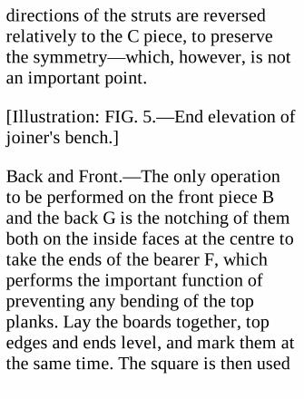
[Illustration: FIG. 5.—End elevation ofjoiner's bench.]
Back and Front.—The only operationto be performed on the front piece Band the back G is the notching of themboth on the inside faces at the centre totake the ends of the bearer F, whichperforms the important function ofpreventing any bending of the topplanks. Lay the boards together, topedges and ends level, and mark them atthe same time. The square is then used
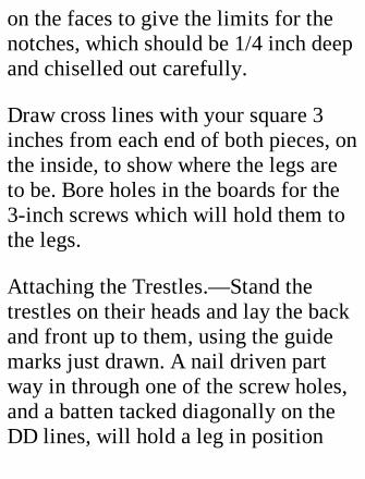
on the faces to give the limits for thenotches, which should be 1/4 inch deepand chiselled out carefully.
Draw cross lines with your square 3inches from each end of both pieces, onthe inside, to show where the legs areto be. Bore holes in the boards for the3-inch screws which will hold them tothe legs.
Attaching the Trestles.—Stand thetrestles on their heads and lay the backand front up to them, using the guidemarks just drawn. A nail driven partway in through one of the screw holes,and a batten tacked diagonally on theDD lines, will hold a leg in position

while the screws are inserted. (Makesure that the tops of the legs and thetop edges of B and G are in the sameplane.)
Affixing the Braces.—The braces DD,of 3 by 1 inch stuff, can now be markedoff and cut exactly down the middle tothe limits of the overlap. Screw on thebraces.
The bearer F is next cut out. Its lengthshould be such as to maintain the exactparallelism of B with G, and the endsbe as square as you can cut them. Fix itin position by two 2-inch screws ateach end.
The bench is now ready for covering.
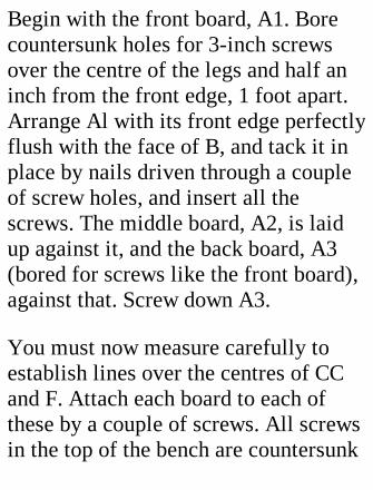
Begin with the front board, A1. Borecountersunk holes for 3-inch screwsover the centre of the legs and half aninch from the front edge, 1 foot apart.Arrange Al with its front edge perfectlyflush with the face of B, and tack it inplace by nails driven through a coupleof screw holes, and insert all thescrews. The middle board, A2, is laidup against it, and the back board, A3(bored for screws like the front board),against that. Screw down A3.
You must now measure carefully toestablish lines over the centres of CCand F. Attach each board to each ofthese by a couple of screws. All screwsin the top of the bench are countersunk
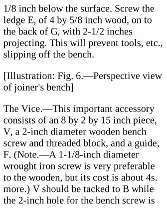
1/8 inch below the surface. Screw theledge E, of 4 by 5/8 inch wood, on tothe back of G, with 2-1/2 inchesprojecting. This will prevent tools, etc.,slipping off the bench.
[Illustration: Fig. 6.—Perspective viewof joiner's bench]
The Vice.—This important accessoryconsists of an 8 by 2 by 15 inch piece,V, a 2-inch diameter wooden benchscrew and threaded block, and a guide,F. (Note.—A 1-1/8-inch diameterwrought iron screw is very preferableto the wooden, but its cost is about 4s.more.) V should be tacked to B whilethe 2-inch hole for the bench screw is
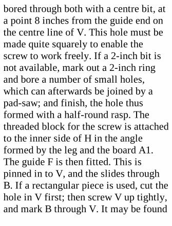
bored through both with a centre bit, ata point 8 inches from the guide end onthe centre line of V. This hole must bemade quite squarely to enable thescrew to work freely. If a 2-inch bit isnot available, mark out a 2-inch ringand bore a number of small holes,which can afterwards be joined by apad-saw; and finish, the hole thusformed with a half-round rasp. Thethreaded block for the screw is attachedto the inner side of H in the angleformed by the leg and the board A1.The guide F is then fitted. This ispinned in to V, and the slides throughB. If a rectangular piece is used, cut thehole in V first; then screw V up tightly,and mark B through V. It may be found
more convenient to use a circularpiece, in which case the holes for it canbe centre-bitted through V and B in oneoperation. If after fitting V projectsabove A, plane it down level.
The finishing touches are rounding offall corners which might catch and fraythe clothes, and boring the 3/4-inchholes, HH, for pegs on which plankscan be rested for edge planing.
For a "stop" to prevent boards slippingwhen being planed on the flat, one mayuse an ordinary 2-inch wood screw, theprojection of which must of course beless than the thickness of the boardplaned. Many carpenters employ this
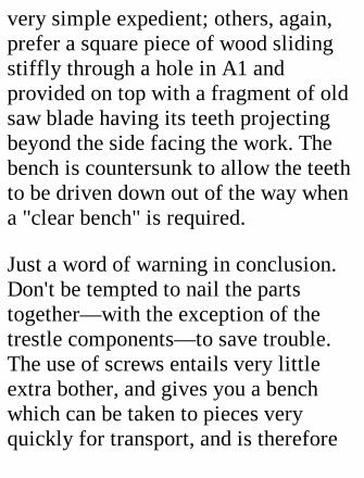
very simple expedient; others, again,prefer a square piece of wood slidingstiffly through a hole in A1 andprovided on top with a fragment of oldsaw blade having its teeth projectingbeyond the side facing the work. Thebench is countersunk to allow the teethto be driven down out of the way whena "clear bench" is required.
Just a word of warning in conclusion.Don't be tempted to nail the partstogether—with the exception of thetrestle components—to save trouble.The use of screws entails very littleextra bother, and gives you a benchwhich can be taken to pieces veryquickly for transport, and is therefore
more valuable than a nailed one.
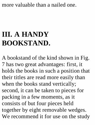
III. A HANDYBOOKSTAND.
A bookstand of the kind shown in Fig.7 has two great advantages: first, itholds the books in such a position thattheir titles are read more easily thanwhen the books stand vertically;second, it can be taken to pieces forpacking in a few moments, as itconsists of but four pieces heldtogether by eight removable wedges.We recommend it for use on the study
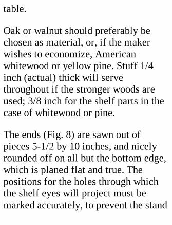
table.
Oak or walnut should preferably bechosen as material, or, if the makerwishes to economize, Americanwhitewood or yellow pine. Stuff 1/4inch (actual) thick will servethroughout if the stronger woods areused; 3/8 inch for the shelf parts in thecase of whitewood or pine.
The ends (Fig. 8) are sawn out ofpieces 5-1/2 by 10 inches, and nicelyrounded off on all but the bottom edge,which is planed flat and true. Thepositions for the holes through whichthe shelf eyes will project must bemarked accurately, to prevent the stand

showing a twist when put together. Thesimplest method of getting the marksright is to cut a template out of thincard and apply it to the two ends inturn, using the base of each as theadjusting line. Fret-saw the holes,cutting just inside the lines to allow fortruing up with a coarse file.
[Illustration: Fig. 7.—Perspective viewof bookstand.]
The shelves a and b are 15 inches long,exclusive of the lugs c, c, c, c, and 4-1/2 and 4-3/4 inches wide respectively.As will be seen from Fig. 8, b overlapsa. Both have their top edges roundedoff to prevent injury to book bindings,
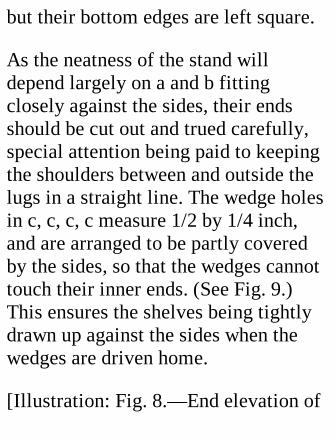
but their bottom edges are left square.
As the neatness of the stand willdepend largely on a and b fittingclosely against the sides, their endsshould be cut out and trued carefully,special attention being paid to keepingthe shoulders between and outside thelugs in a straight line. The wedge holesin c, c, c, c measure 1/2 by 1/4 inch,and are arranged to be partly coveredby the sides, so that the wedges cannottouch their inner ends. (See Fig. 9.)This ensures the shelves being tightlydrawn up against the sides when thewedges are driven home.
[Illustration: Fig. 8.—End elevation of
bookstand.]
The wedges should be cut on a veryslight taper of not more than half aninch in the foot run, in order to keeptheir grip. Prepare a strip as thick asthe smaller dimension of the holes, 3/8inch wide at one end, and 7/8 inch wideat the other. Assemble the parts andpush the piece through a hole until itgets a good hold, mark it across half aninch above the hole, and cut it off.Then plane the strip down parallel tothe edge that follows the grain until theend will project half an inch beyond thelug next fitted. Mark and cut off asbefore, and repeat the process until theeight wedges are ready in the rough.
Then bevel off the outside corners andsmooth them—as well as the rest of thewoodwork—with fine glass paper.
Shelves and sides should be wax-polished or given a coat or two ofvarnish.
[Illustration: Fig. 9. Plan or bookstandshelf.]
Don't drive the wedges in too tight, oryon may have to lament a split lug.
If the stand is to be used for very heavybooks, or the shelves are much longerthan specified here, it is advisable tobring the angle of the shelves down tothe bottom of the standards, to relieve
the shelves of bending strain at thecentre; or to use stouter material; or tounite the shelves at two or three pointsby thin brass screws inserted throughholes drilled in the overlapping part.
IV. A HOUSE LADDER.
The preparation and putting together ofthe parts of a ladder having round,tapered rungs let into holes in the twosides is beyond the capacity of theaverage young amateur; but little skillis needed to manufacture a very fairlyefficient substitute for the

professionally-built article—to wit, aladder of the kind to which buildersapply the somewhat disparagingadjective "duck."
The rungs of such a "duck" ladder aremerely nailed to the outside if theladder is required for temporarypurposes only; but as we are of courseaiming at the construction of a thingmade to last, we shall go to the troubleof "notching-in" each rung (see Fig.10), so that the sides shall take theweight directly, and the nails only haveto keep the rungs firmly in position.The objection to notching-in is that itreduces the strength of the ladder,which is of course only that of the

wood between the bottom of thenotches and the plain side. Therefore itis necessary to have sides somewhatdeeper than would be required for acentrally-runged ladder; which ispierced where the wood is subjected tolittle tension or compression.
[Illustration: Fig. 10—House ladderand details of letting in a rung]
Materials.—The length of the ladderwill decide what the stoutness of thesides should be. For a ladder about 12feet long, such as we propose todescribe, larch battens 3 by 1-1/8inches (actual) in section and free fromknots, especially at the edges, will be
sufficiently strong to carry allreasonable weights without danger ofcollapse. But be sure to get the bestwood obtainable. The rungs may be of2 by 1 inch stuff, though 2 by 3/4 inchwill suffice for the upper half-dozen,which have less wear, and are shorterthan those below.
The rungs are 10 inches apart (Fig. 10),centre to centre. The distance may beincreased to a foot, Or even more ifweight-saving is an object.
CONSTRUCTION.
Preparing the Sides.—These are cut to
exactly the same length, which we willassume to be 11 feet 6 inches, planedquite smooth and rounded off slightlyat the corners to make handlingcomfortable. Before marking them forthe rungs it is important that they shallbe so arranged that both incline equallytowards a centre line.
Stretch a string tightly three inchesabove the ground, and lay the sides ofthe ladder on edge to right and left ofit, their ends level. Adjust the bottomends 8-1/2, the top ends 6-1/2 inchesfrom the string, measuring from theoutside. Tack on cross pieces toprevent shifting, and then, startingfrom the bottom, make a mark every 10
inches on the outside corners, to showthe position of the tops of the rungs. Apiece of the wood to be used formaking the rungs of is laid up to thepairs of marks in turn, and lines aredrawn on both sides of it.
Cutting the Notches.—The work ofmarking the ends of the notches will bequickened, and rendered more accurate,if a template (Fig. 10) is cut out of tin.The side AC is 3/8 to 1/2 inch deep.Apply the template to both faces of theside in turn, with its corner A at theline below the rung, and DE flush withthe upper corner. When all the notcheshave been marked cut down the ACline of each with a tenon saw, and
chisel along BC till the wedge-shapedchip is removed. Finish off every notchas neatly as possible, so that the rungsmay make close contact and keep waterout.
Preparing the Rungs.—Lay a piece ofrung batten across the lowest notches,the end overhanging the side by aquarter of an inch or so to allow for thetaper of the ladder, and draw yourpencil along the angles which it makeswith the sides. Mark the positions ofthe nail holes. Cut off the rung at thecross lines; drill the four nail holes onthe skew, as shown in Fig. 10; andround off all the corners. The otherrungs are treated in the same manner,
and the sides are then separated, for theinside top corner and both backcorners, which will be handled most, tobe well rounded off and rubbed smoothwith glass paper.
Assembling.—Before putting the partstogether give them a coating of paint,as the contact surfaces will not beaccessible to the brush afterwards.When the paint has dried, lay the sidesout as before, and nail on the rungswith 3-inch nails. To counteract anytendency of the sides to draw apart, alight cross bar should be fixed on theback of the ladder behind the top andbottom rungs.
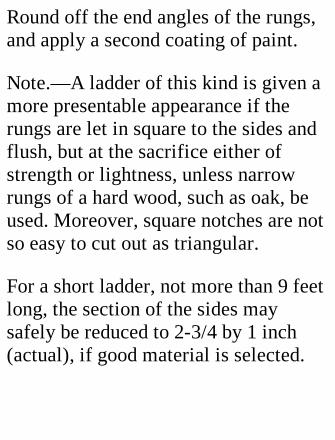
Round off the end angles of the rungs,and apply a second coating of paint.
Note.—A ladder of this kind is given amore presentable appearance if therungs are let in square to the sides andflush, but at the sacrifice either ofstrength or lightness, unless narrowrungs of a hard wood, such as oak, beused. Moreover, square notches are notso easy to cut out as triangular.
For a short ladder, not more than 9 feetlong, the section of the sides maysafely be reduced to 2-3/4 by 1 inch(actual), if good material is selected.
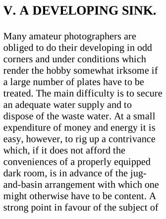
V. A DEVELOPING SINK.
Many amateur photographers areobliged to do their developing in oddcorners and under conditions whichrender the hobby somewhat irksome ifa large number of plates have to betreated. The main difficulty is to securean adequate water supply and todispose of the waste water. At a smallexpenditure of money and energy it iseasy, however, to rig up a contrivancewhich, if it does not afford theconveniences of a properly equippeddark room, is in advance of the jug-and-basin arrangement with which onemight otherwise have to be content. Astrong point in favour of the subject of
this chapter is that it can be movedwithout any trouble if the photographerhas to change his quarters.
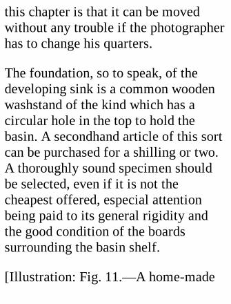
The foundation, so to speak, of thedeveloping sink is a common woodenwashstand of the kind which has acircular hole in the top to hold thebasin. A secondhand article of this sortcan be purchased for a shilling or two.A thoroughly sound specimen shouldbe selected, even if it is not thecheapest offered, especial attentionbeing paid to its general rigidity andthe good condition of the boardssurrounding the basin shelf.
[Illustration: Fig. 11.—A home-made
developing sink for the darkroom.]
The area of the top is generally about20 by 15 inches; but if a stand of largerdimensions can be found, choose it bypreference.
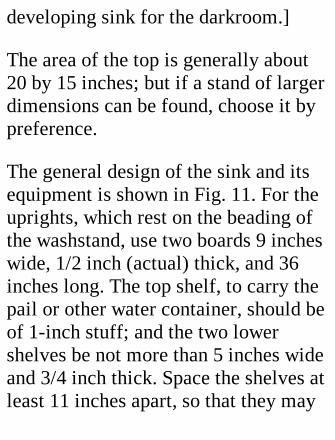
The general design of the sink and itsequipment is shown in Fig. 11. For theuprights, which rest on the beading ofthe washstand, use two boards 9 incheswide, 1/2 inch (actual) thick, and 36inches long. The top shelf, to carry thepail or other water container, should beof 1-inch stuff; and the two lowershelves be not more than 5 inches wideand 3/4 inch thick. Space the shelves atleast 11 inches apart, so that they may
accommodate tall bottles. Thesuperstructure will gain in rigidity ifthe intermediate shelves are screwed tothe uprights, in addition to beingsupported on ledges as indicated; and ifthe back is boarded over for at leasthalf its height, there will be no dangerof sideways collapse, when a fullbucket is put in position.
The top of the washstand, on which thedeveloping will be done, must beprovided with a tray of lead or zinc.Lead is preferable, as lying flatter; butthe jointing at the corners is moredifficult than the soldering of sheetzinc, which, though more liable tochemical corrosion, is much lighter
than the thinnest lead—weighing about1-1/2 lbs. to the square foot—thatcould well be used. If lead is selected,the services of a plumber had better besecured, if the reader has had noexperience in "wiping a joint."
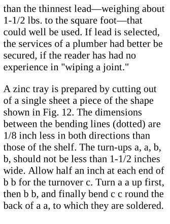
A zinc tray is prepared by cutting outof a single sheet a piece of the shapeshown in Fig. 12. The dimensionsbetween the bending lines (dotted) are1/8 inch less in both directions thanthose of the shelf. The turn-ups a, a, b,b, should not be less than 1-1/2 incheswide. Allow half an inch at each end ofb b for the turnover c. Turn a a up first,then b b, and finally bend c c round theback of a a, to which they are soldered.
A drop of solder will be needed in eachcorner to make it water-tight. Whenturning up a side use a piece of square-cornered metal or wood as mould, andmake the angles as clean as possible,especially near the joints.
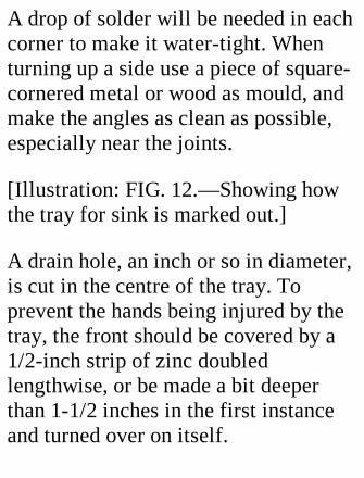
[Illustration: FIG. 12.—Showing howthe tray for sink is marked out.]
A drain hole, an inch or so in diameter,is cut in the centre of the tray. Toprevent the hands being injured by thetray, the front should be covered by a1/2-inch strip of zinc doubledlengthwise, or be made a bit deeperthan 1-1/2 inches in the first instanceand turned over on itself.
Before the tray is put in position thebasin hole must be filled in, except foran opening to take the waste pipe. Theplug is pad-sawed out of wood of thesame thickness as the top, to which it isattached by crossbars on the under side.The whole of the woodwork, or at leastthose parts which are most likely to getwetted, should then be given a coat ortwo of paint.
A waste pipe, somewhat larger than thedrain hole and 3 inches long, havingbeen firmly soldered to the tray, beatthe edges of the hole down into thepipe. Then prepare a wooden collar tofit the pipe outside, and drill a hole onthe centre line to take a carpenter's
screw. If the edges of the tray aresupported on slats 3/16 to 1/4 inchthick, and its centre is kept in contactwith the wood by the collar pressingagainst the underside of the shelf, anywater will naturally gravitate to thecentre and escape by the waste pipe.This automatic clearance of "slops" is avery desirable feature of a developingsink.
To prevent water splashing on to thesides of the stand and working downbetween tray and wood, tack pieces ofAmerican cloth on the sides with theiredges overlapping the tray edges by aninch or so.
A small two-handled bath is the mostconvenient receptacle for the wastewater. It should hold at least a quarteras much again as the water tank, so asto avoid any danger of overfilling. Apiece of old cycle tyre tubing, tied tothe waste pipe and long enough toreach below the edge of the bath, willprevent splashing—which, whenchemicals are being poured away,might prove disastrous to light-coloured clothes.
The supply pipe has a siphon-piece of"compo" tubing at the top, to draw offthe water when the tube has been filledby suction, and a small tap at thebottom. This tap, when not in use,
should be held back out of the way by awire hook attached to the lowest of theupper shelves. A piece of linoleumshould be cut to fit the bath-shelf andprotect the drawer below.
VI. A POULTRY HOUSEAND RUN.
This chapter should be of interest to thekeeper of poultry on a small scale, foreven if the instructions given are notfollowed out quite as they stand, theymay suggest modifications to suit thetaste and means of the reader.
The principle of the combined run andhouse—which will accommodate adozen fowls without overcrowding,especially if it be moved from time totime on to fresh ground—will beunderstood from Figs. 13 and 14. Thefirst of these shows the framework towhich the boards for the house and thewire for the run are nailed. Its over-alllength of 10 feet is subdivided into five"bays" or panels, 2 feet long (nearly)between centres of rafters. Two baysare devoted to the house, three to therun.
[Illustration: Fig. 13.—Frame forpoultry house and run (above).Completed house and run (below).]
One square (10 by 10 feet) of weatherboarding 6 inches wide, for covering inthe house. 44 feet of 4 by 1, for baseand ridge. 56 feet of 3 by 1, for eightrafters. 28 feet of 3 by 1-1/2, for fourrafters. 50 feet of 2 by 1-1/2, for doorframes and doors. 6 feet of 2 by 2, fortie t. 45 feet of 2-foot wire netting.Two pairs of hinges; two locks; staples,etc.
The materials used comprise:— Thetotal cost as estimated from pricescurrent at the time of writing is 25s.This cost could be considerablyreduced by using lighter stuff allthrough for the framework and doors
and by covering in the house with oldboards, which may be picked upcheaply if one is lucky. Whether it isadvisable to sacrifice durability andrigidity to cost must be left to themaker to decide. Anyhow, if thespecifications given are followed, anoutfit warranted to last for severalyears will be produced.
A Few Points.—The vertical height ofthe run is just under 6 feet, the tipsbeing cut away from the rafters at theapex. The width at the ground isexactly 6 feet. The base angles made byAA with B (Fig. 14) are 63 degrees;that which they make with one another,54 degrees. The rafters r1 and r3 at
each end of the house are half an inchthicker than the rest, as they have tostand a lot of nailing.
CONSTRUCTION.
Cutting the Rafters.—If floor space isavailable, chalk out accurately theexternal outline of a pair of rafters (80inches long each before shaping) and aline joining their lower ends. Thendraw a line bisecting the ridge angle.With this template as guide the rafterscan be quickly cut to shape. Anothermethod is to cut one rafter out verycarefully, making a notch for half thewidth of the ridge, and to use it as a
pattern for the rest. In any case thechalked lines will prove useful in thenext operation of pairing the raftersand uniting them by a tie just under theridge notch. Cut a 4 by 1 inch notch atthe bottom of each rafter, on theoutside, for the base piece. The two endpairs have the B pieces (Fig. 14) nailedon to them, and r3 the tie t, whichshould be in line with the rafters. Theother three pairs require temporary tieshalfway up to prevent straddling duringerection.
Door Frames and Doors.—The methodof fixing the frame of the door at therun end is shown in Fig. 14. Thematerial for the frame being 1/2 inch
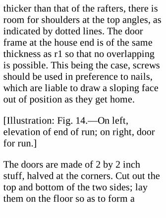
thicker than that of the rafters, there isroom for shoulders at the top angles, asindicated by dotted lines. The doorframe at the house end is of the samethickness as r1 so that no overlappingis possible. This being the case, screwsshould be used in preference to nails,which are liable to draw a sloping faceout of position as they get home.
[Illustration: Fig. 14.—On left,elevation of end of run; on right, doorfor run.]
The doors are made of 2 by 2 inchstuff, halved at the corners. Cut out thetop and bottom of the two sides; laythem on the floor so as to form a
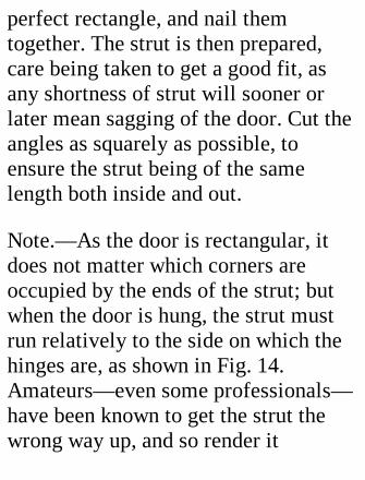
perfect rectangle, and nail themtogether. The strut is then prepared,care being taken to get a good fit, asany shortness of strut will sooner orlater mean sagging of the door. Cut theangles as squarely as possible, toensure the strut being of the samelength both inside and out.
Note.—As the door is rectangular, itdoes not matter which corners areoccupied by the ends of the strut; butwhen the door is hung, the strut mustrun relatively to the side on which thehinges are, as shown in Fig. 14.Amateurs—even some professionals—have been known to get the strut thewrong way up, and so render it
practically useless.
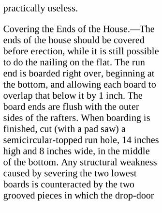
Covering the Ends of the House.—Theends of the house should be coveredbefore erection, while it is still possibleto do the nailing on the flat. The runend is boarded right over, beginning atthe bottom, and allowing each board tooverlap that below it by 1 inch. Theboard ends are flush with the outersides of the rafters. When boarding isfinished, cut (with a pad saw) asemicircular-topped run hole, 14 incheshigh and 8 inches wide, in the middleof the bottom. Any structural weaknesscaused by severing the two lowestboards is counteracted by the twogrooved pieces in which the drop-door
moves.
Odds and ends of weather boardsshould be kept for the door end of thehouse, which requires short piecesonly, and is not boarded below the topof b2. The door may be weather-boarded to match the rest of the end, orcovered by a few strakes of match-boarding put on vertically.
The two base pieces, b1 and b2, and theridge should be marked off for therafters at the same time. All three are10-foot lengths of 4 by 1 wood, unlessyou prefer the ridge to project a bit, inwhich case you must allowaccordingly.
Stand all three pieces together on edge,and make the marks with a squareacross the tops. Allow a distance of 4feet between the outside faces of r1 andr3; halve this distance to get the centreof r2; and subdivide the distancebetween r3 and r6 so that each rafter isseparated from its neighbours by anequal space, which will be 1 foot 11inches. Number the marks and continuethem down the sides of the boards withthe square. There should be a mark oneach side of the place to be occupied bythe intermediate rafters, to preventmistakes; for it is obvious that if arafter is fixed on the left side of asingle ridge mark and on the right ofthe corresponding mark on the base,
the result will not be pleasing.
Erection.—The services of a secondpair of hands are needed here, to holdwhile nailing is done. Nail holes havingbeen drilled in the tops of the raftersand in the base pieces, the ends arestood upright and tacked to the ridge atthe places marked for them, and afterthem the intermediate rafters, workingfrom one end to the other. Then tack onthe base pieces, b1, b3. Get the endsquite perpendicular, and nail atemporary cross strut or two on theoutside of the rafters to preventshifting while the final nailing up isdone.
Covering the Shed.—Sixteen boards, 4feet 2 inches long, are needed for eachside, as, owing to the overlap of oneinch, each tier covers only five of the80 inches. The ridge is made watertightby a strip of sheet zinc, a foot wide,bent over the top and nailed along eachedge.
Waterproofing.—All the woodworkshould now be given a coating of well-boiled tar, paint, creosote, or someother preservative, worked well downinto the cracks. Creosote and stoprotare most convenient to use, as they dryquickly.
Netting.—When the preservative has
dried, fix on the netting with 3/4-inchwire staples. Begin at the base on oneside, strain the netting over the ridge,and down to the base on the other side.Be careful not to draw the rafters out ofline sideways. The last edge stapledshould be that on the roof of the house.
Note.—When driving nails or staplesinto a rafter or other part, get a helperto hold up some object considerablyheavier than the hammer on the fartherside to deaden the blow. Lack of suchsupport may cause damage, besidesmaking the work much more tediousand difficult.
Finishing off.—The doors are now
hung, and fitted with buttons andpadlocks. The stops should be on thedoors, not on the frames, where theywould prove an obstruction in asomewhat narrow opening. Perchesshould be of 2 by 1 inch wood, roundedoff at the top, and supported in socketsat each end so as to be removable forcleaning; and be all on the same level,to avoid fighting for the "upper seats"among the fowls. A loose floor, madein two pieces for convenience ofmoving, will help to keep the fowlswarm and make cleaning easier, butwill add a few shillings to the cost. Theinside of the house should be wellwhitewashed before fowls areadmitted. To prevent draughts the
triangular spaces between the roofboards and rafters should be plugged,but ample ventilation must be providedfor by holes bored in the ends of thehouse at several elevations, the lowest2 feet above the base. Handles forlifting may be screwed to the faces of band b2 halfway between the door frameand the corners.
VII. A SHED FOR YOURBICYCLE.
The problem, how to house one ormore cycles, often gives trouble to the

occupiers of small premises. The hall-way, which in many cases has to serveas stable, is sadly obstructed by thehandles of a machine; and if one is keptthere, the reason generally is that noother storage is available.
If accommodation is neededpermanently for two or three cyclesbelonging to the house, andoccasionally for the machine of avisitor, and if room is obtainable in abackyard or garden in directcommunication with the road, thequestion of constructing a reallydurable and practical cycle shed is wellworth consideration. I say constructing,because, in the first place, a bought
shed costing the same money wouldprobably not be of such good quality asa home-made one; and secondly,because the actual construction, whilenot offering any serious difficulty, willafford a useful lesson in carpentry.
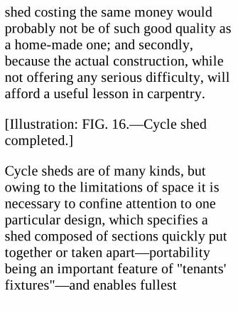
[Illustration: FIG. 16.—Cycle shedcompleted.]
Cycle sheds are of many kinds, butowing to the limitations of space it isnecessary to confine attention to oneparticular design, which specifies ashed composed of sections quickly puttogether or taken apart—portabilitybeing an important feature of "tenants'fixtures"—and enables fullest
advantage to be taken of the storageroom. As will be seen from the scaledrawings illustrating this chapter, thedoors extend right across the front, andwhen they are open the whole of theinterior is easily accessible. The factthat the cycles can be put in sidewaysis a great convenience, as the standingof the machines head to tail alternatelyeconomizes room considerably.
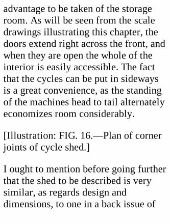
[Illustration: FIG. 16.—Plan of cornerjoints of cycle shed.]
I ought to mention before going furtherthat the shed to be described is verysimilar, as regards design anddimensions, to one in a back issue of

Cycling. By the courtesy of theproprietors of the journal I have beenpermitted to adapt the description theregiven.[1]
[Footnote 1: By Mr. Hubert Burgess. ]
Dimensions and GeneralArrangements.—The shed is 8 feetlong over all, 5 feet 6 inches high infront, 5 feet high at the back, 3 feetdeep over all, under the roof, whichprojects 3 inches fore and aft, and 2inches at each end. It consists of sevenparts: two sides, roof, back, front frameand doors, and a bottom in twosections.
The reader should examine the
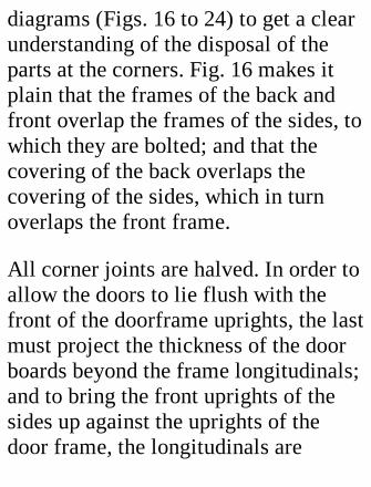
diagrams (Figs. 16 to 24) to get a clearunderstanding of the disposal of theparts at the corners. Fig. 16 makes itplain that the frames of the back andfront overlap the frames of the sides, towhich they are bolted; and that thecovering of the back overlaps thecovering of the sides, which in turnoverlaps the front frame.
All corner joints are halved. In order toallow the doors to lie flush with thefront of the doorframe uprights, the lastmust project the thickness of the doorboards beyond the frame longitudinals;and to bring the front uprights of thesides up against the uprights of thedoor frame, the longitudinals are
notched, as shown (Fig. 16), to thedepth of the set-back for the doors.
Materials.—The question of cost andthe question of materials cannot beseparated. A shed even of thedimensions given consumes a lot ofwood, and the last, that it maywithstand our variable and treacherousclimate for a good number of years,should, as regards those parts directlyexposed to the weather, be of goodquality. Yellow deal may be selectedfor the boards; pitch pine is better, butit costs considerably more. For theframes and non-exposed partsgenerally ordinary white deal willsuffice.
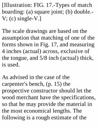
[Illustration: FIG. 17.-Types of matchboarding: (a) square joint; (b) double.-V; (c) single-V.]
The scale drawings are based on theassumption that matching of one of theforms shown in Fig. 17, and measuring4 inches (actual) across, exclusive ofthe tongue, and 5/8 inch (actual) thick,is used.
As advised in the case of thecarpenter's bench, (p. 15) theprospective constructor should let thewood merchant have the specifications,so that he may provide the material inthe most economical lengths. Thefollowing is a rough estimate of the
wood required, allowing a sufficientmargin for waste:
4-1/2 (over tongue) by 5/8 inch (actual)yellow match boarding for sides, roof,back, and doors:
1-1/2 squares = 150 sq. feet. = 450 feetrun. White 4-1/2 by 3/4 inch square-shouldered flooring: 1/4 square = 25sq. feet. = 75 feet run. 3 by 1-1/2 inchbattens = 88 feet run. 4 by 1-1/2 inchbattens = 26 feet run. 3 by 2 inchbattens = 27 feet run. 5 by 1-1/2 inchbattens = 8 feet run. 2 by 1-1/2 inchbattens = 21 feet run.
There will also be required:Twelve 6-inch bolts and nuts.
Two pairs 18-inch cross-garnet hinges.Two door bolts.One lock (a good one).Four yards of roofing felt.Two gallons of stoprot.Three lbs. wire-nailsA few dozen 3-inch and I-1/2-inchscrews.
The total cost of the materials willcome to about 2 pounds, 2s.
CONSTRUCTION.
The scale drawings are so complete asto dimensions that, assuming thematerials to be of the sizes specified,
they may be followed implicitly. It is,of course, easy to modify the design tosuit any slight differences indimensions; and to avoid mistakes allthe stuff should be gauged carefullybeforehand.
[Illustration: FIG. 18.-Side of cycleshed.]
The Sides.—When laying out theframes for these it is necessary to bearin mind that the front upright issomewhat less than 5 feet 6 incheslong, and the back upright rather morethan 5 feet, owing to the slope of theroof, and to the fact that they are set in2 inches from the back and front. To
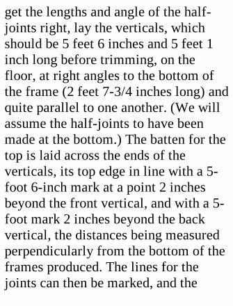
get the lengths and angle of the half-joints right, lay the verticals, whichshould be 5 feet 6 inches and 5 feet 1inch long before trimming, on thefloor, at right angles to the bottom ofthe frame (2 feet 7-3/4 inches long) andquite parallel to one another. (We willassume the half-joints to have beenmade at the bottom.) The batten for thetop is laid across the ends of theverticals, its top edge in line with a 5-foot 6-inch mark at a point 2 inchesbeyond the front vertical, and with a 5-foot mark 2 inches beyond the backvertical, the distances being measuredperpendicularly from the bottom of theframes produced. The lines for thejoints can then be marked, and the
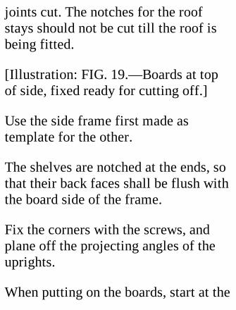
joints cut. The notches for the roofstays should not be cut till the roof isbeing fitted.
[Illustration: FIG. 19.—Boards at topof side, fixed ready for cutting off.]
Use the side frame first made astemplate for the other.
The shelves are notched at the ends, sothat their back faces shall be flush withthe board side of the frame.
Fix the corners with the screws, andplane off the projecting angles of theuprights.
When putting on the boards, start at the

back of the frame. Plane down thegroove edge of the first board until thegroove is out of the board, and applythe board with 1-1/2 inches projectingbeyond the frame. Leave a little spareat each end of every board, and whenthe side is covered run a tenon-sawacross both ends of all the boards closeto the frame, and finish up with theplane. This is quicker and makes aneater job than cutting each board tosize separately.
[Illustration: FIG. 20.-Back of cycleshed.]
The Back (Fig. 20).—When laying outthe frame for this, remember that there
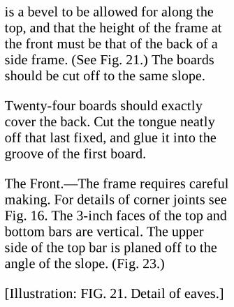
is a bevel to be allowed for along thetop, and that the height of the frame atthe front must be that of the back of aside frame. (See Fig. 21.) The boardsshould be cut off to the same slope.
Twenty-four boards should exactlycover the back. Cut the tongue neatlyoff that last fixed, and glue it into thegroove of the first board.
The Front.—The frame requires carefulmaking. For details of corner joints seeFig. 16. The 3-inch faces of the top andbottom bars are vertical. The upperside of the top bar is planed off to theangle of the slope. (Fig. 23.)
[Illustration: FIG. 21. Detail of eaves.]
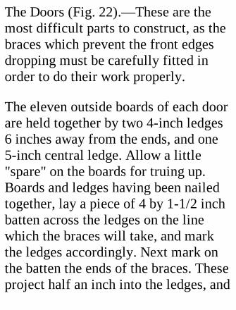
The Doors (Fig. 22).—These are themost difficult parts to construct, as thebraces which prevent the front edgesdropping must be carefully fitted inorder to do their work properly.
The eleven outside boards of each doorare held together by two 4-inch ledges6 inches away from the ends, and one5-inch central ledge. Allow a little"spare" on the boards for truing up.Boards and ledges having been nailedtogether, lay a piece of 4 by 1-1/2 inchbatten across the ledges on the linewhich the braces will take, and markthe ledges accordingly. Next mark onthe batten the ends of the braces. Theseproject half an inch into the ledges, and
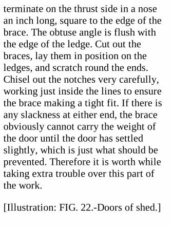
terminate on the thrust side in a nosean inch long, square to the edge of thebrace. The obtuse angle is flush withthe edge of the ledge. Cut out thebraces, lay them in position on theledges, and scratch round the ends.Chisel out the notches very carefully,working just inside the lines to ensurethe brace making a tight fit. If there isany slackness at either end, the braceobviously cannot carry the weight ofthe door until the door has settledslightly, which is just what should beprevented. Therefore it is worth whiletaking extra trouble over this part ofthe work.
[Illustration: FIG. 22.-Doors of shed.]
Cautions.—Don't get the nose of thebrace too near the end of the ledge.Nail the boards on specially securely tothe ledges near the ends of the braces.
Fitting the Doors.—The doors shouldnow be laid on the top of the frame andsecured to it by the four hinges. Thelong ends of these are held by screwsdriven through the boards into thebearers; the cross pieces are screwed tothe uprights of the door frame. Thedoors when closed should make a goodbut not tight fit with one another.
PUTTING THE PARTSTOGETHER.
The two sides, front, and back are nowassembled, on a level surface, fordrilling the holes for the bolts whichhold them together. The positions ofthe bolts will be gathered from thedrawings. Get the parts quite squarebefore drilling, and run the holesthrough as parallel to the sides aspossible. If the bolts are a bit too long,pack washers between nut and wooduntil the nut exerts proper pressure.
Caution.—The hole must not be largeenough to allow the square part justunder the head to revolve, for in such acase it would be impossible to screw upthe nut. Its size ought to be such as torequire the head to be driven up against
the wood.
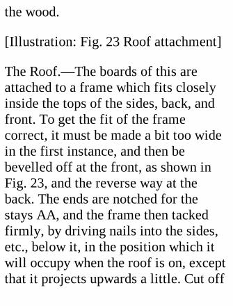
[Illustration: Fig. 23 Roof attachment]
The Roof.—The boards of this areattached to a frame which fits closelyinside the tops of the sides, back, andfront. To get the fit of the framecorrect, it must be made a bit too widein the first instance, and then bebevelled off at the front, as shown inFig. 23, and the reverse way at theback. The ends are notched for thestays AA, and the frame then tackedfirmly, by driving nails into the sides,etc., below it, in the position which itwill occupy when the roof is on, exceptthat it projects upwards a little. Cut off
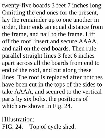
twenty-five boards 3 feet 7 inches long.Omitting the end ones for the present,lay the remainder up to one another inorder, their ends an equal distance fromthe frame, and nail to the frame. Liftoff the roof, insert and secure AAAA,and nail on the end boards. Then ruleparallel straight lines 3 feet 6 inchesapart across all the boards from end toend of the roof, and cut along theselines. The roof is replaced after notcheshave been cut in the tops of the sides totake AAAA, and secured to the verticalparts by six bolts, the positions ofwhich are shown in Fig. 24.
[Illustration:FIG. 24.—Top of cycle shed.
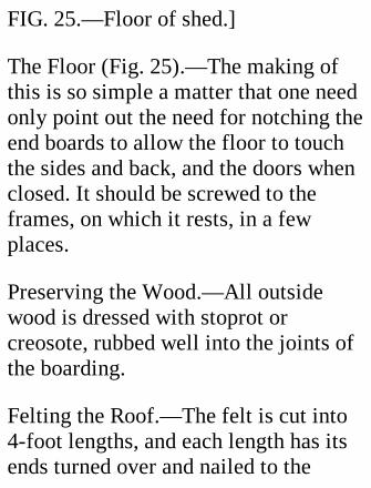
FIG. 25.—Floor of shed.]
The Floor (Fig. 25).—The making ofthis is so simple a matter that one needonly point out the need for notching theend boards to allow the floor to touchthe sides and back, and the doors whenclosed. It should be screwed to theframes, on which it rests, in a fewplaces.
Preserving the Wood.—All outsidewood is dressed with stoprot orcreosote, rubbed well into the joints ofthe boarding.
Felting the Roof.—The felt is cut into4-foot lengths, and each length has itsends turned over and nailed to the
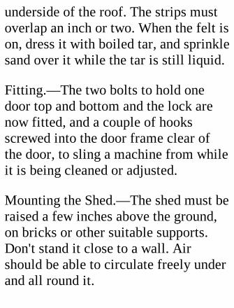
underside of the roof. The strips mustoverlap an inch or two. When the felt ison, dress it with boiled tar, and sprinklesand over it while the tar is still liquid.
Fitting.—The two bolts to hold onedoor top and bottom and the lock arenow fitted, and a couple of hooksscrewed into the door frame clear ofthe door, to sling a machine from whileit is being cleaned or adjusted.
Mounting the Shed.—The shed must beraised a few inches above the ground,on bricks or other suitable supports.Don't stand it close to a wall. Airshould be able to circulate freely underand all round it.

CUTTING DOWN EXPENSE.
If the cost appears prohibitive, it maybe reduced somewhat (1) by usingthinner boards; (2) by reducing theheight of the shed by 1 foot. A verycheap shed, but of course notcomparable in quality with the onedescribed, can be made by using oddrough boards for the outside, andcovering them with roofing felt welltarred.
VIII. A TARGETAPPARATUS FOR RIFLE
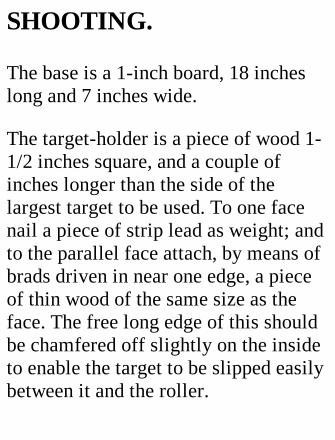
SHOOTING.
The base is a 1-inch board, 18 incheslong and 7 inches wide.
The target-holder is a piece of wood 1-1/2 inches square, and a couple ofinches longer than the side of thelargest target to be used. To one facenail a piece of strip lead as weight; andto the parallel face attach, by means ofbrads driven in near one edge, a pieceof thin wood of the same size as theface. The free long edge of this shouldbe chamfered off slightly on the insideto enable the target to be slipped easilybetween it and the roller.
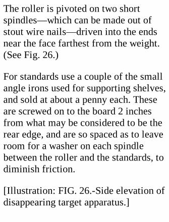
The roller is pivoted on two shortspindles—which can be made out ofstout wire nails—driven into the endsnear the face farthest from the weight.(See Fig. 26.)
For standards use a couple of the smallangle irons used for supporting shelves,and sold at about a penny each. Theseare screwed on to the board 2 inchesfrom what may be considered to be therear edge, and are so spaced as to leaveroom for a washer on each spindlebetween the roller and the standards, todiminish friction.
[Illustration: FIG. 26.-Side elevation ofdisappearing target apparatus.]
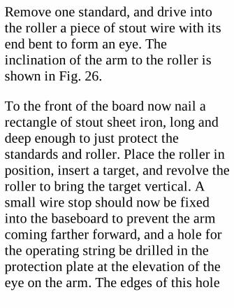
Remove one standard, and drive intothe roller a piece of stout wire with itsend bent to form an eye. Theinclination of the arm to the roller isshown in Fig. 26.
To the front of the board now nail arectangle of stout sheet iron, long anddeep enough to just protect thestandards and roller. Place the roller inposition, insert a target, and revolve theroller to bring the target vertical. Asmall wire stop should now be fixedinto the baseboard to prevent the armcoming farther forward, and a hole forthe operating string be drilled in theprotection plate at the elevation of theeye on the arm. The edges of this hole

need careful smoothing off to preventfraying of the string. A small eyelet orbrass ring soldered into or round thehole will ensure immunity fromchafing.
Drive a couple of long wire nails intothe front edge of the board outside theiron screen to wind the string on whenthe target is put away.
It may prove a convenience if plainmarks are made on the string at thedistances from which shooting will bedone.
The above description covers apparatusfor working two or more targetssimultaneously on a long roller, or
separately on separate rollers mountedon a common baseboard.
If it is desired to combine with theapparatus a "stop" for the bullets, thelatter (a sheet of stout iron of therequisite strength) may be affixed tothe rear of the baseboard, and furnishedwith a handle at the top to facilitatetransport.
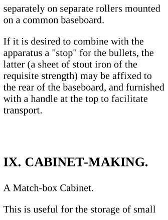
IX. CABINET-MAKING.
A Match-box Cabinet.
This is useful for the storage of small
articles, such as stamps, pens, seeds,needles, and a number of other minorthings which easily go astray if put in adrawer with larger objects.
The best boxes for the purpose arethose used for the larger Bryant andMay matches. Select only those boxesof which the tray moves easily in thecase.
The cases should be stood on end onsome flat surface while being gluedtogether. A box or drawer with trulysquare corners is useful for assemblingthem in; if they are packed into onecorner they cannot slew about. Pressthe boxes together while the glue is
setting.
Now glue the back ends of the cases(from which the trays should have beenremoved), and press them against apiece of thin card. When the glue isdry, apply some more with a smallbrush to the back angles inside thecovers, to ensure a good hold on thebacking. Trim off the card to theoutline of the pile.
[Illustration: FIG. 27.—Match-boxcabinet.]
Select for the front end of the drawerthat for which the wood is doubledover. Paste outside the end a piece ofwhite paper, whereon words and
numbers will be more plainly visible.The life of the trays will be increased ifthe insides are neatly lined with thinpaper.
For "handles" use boot buttons, orloops of thin brass wire, or brass paperclips. To give the cabinet a neatappearance you should cover it outsidewith paper of some neutral tint; and ifyou wish it to be stable and not upsetwhen a rather sticky drawer is pulledout, glue it down to a solid woodenbase of the proper size.
A Cardboard Cabinet.
We now proceed to a more ambitious
undertaking—the manufacture of acabinet for the storage of note-paper,envelopes, labels, etc. The onlymaterials needed are some cardboardand glue; the tools, a ruler and a verysharp knife. For the marking out adrawing board and T-square areinvaluable. The cardboard should befairly stout, not less than 1/16 inchthick.
Begin with the drawers; it is easier tomake the case fit the drawers than viceversa.
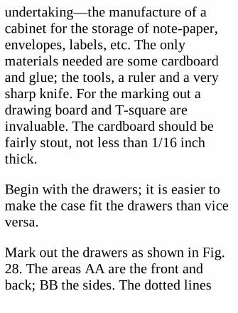
Mark out the drawers as shown in Fig.28. The areas AA are the front andback; BB the sides. The dotted lines
indicate the lines along which thecardboard is bent up. The sides are ofexactly the same length as the bottom,but the front and back are longer thanthe bottom by twice the thickness ofthe cardboard, so as to overlap thesides. (The extra length is indicated bythe heavy black lines.)
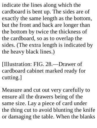
[Illustration: FIG. 28.—Drawer ofcardboard cabinet marked ready forcutting.]
Measure and cut out very carefully toensure all the drawers being of thesame size. Lay a piece of card underthe thing cut to avoid blunting the knifeor damaging the table. When the blanks
are ready, cut them almost throughalong the dotted lines. Use severalstrokes, and after each stroke test thestubbornness of the bend. When thecard is almost severed it will bend upquite easily. Note.—Bend as shown inthe inset C; not the other way, or youwill snap the card. If you should be sounlucky as to cut the card through inplaces, paste a strip of thin paper alongthe line before turning up.
The four flaps are now bent up, gluedtogether, and covered outside withpaper. This part of the business is easyenough if a small square-corneredwooden box be used as a support insideat each angle in turn. It is advisable to
glue strips along all the bends bothinside and outside. The external stripsshould be flattened down well, so as tooffer no loose edges.
Compare the drawers, and if one isslightly wider than the rest, use it toguide you in making the measurementsfor the case.
The sides and back of the case are cutout of a single piece. The sides shouldbe a quarter of an inch deeper than thedrawers to allow some overlap; theback slightly wider than the drawer.
As each drawer will be separated fromthat above it by a shelf, allowance mustbe made for the shelves, and also for a

twentieth of an inch or so of "play" toeach drawer. To keep on the safe sideleave a little extra stuff to be removedlater on.
Cut out the bottom to fit inside theback and sides exactly, and a sufficientnumber of shelves of precisely thesame size as the bottom. Attach thebottom to the sides and back withinternal and external strips. When theglue has set, place the guide drawer inposition, and lay on it a piece of thincard to cover it over. This card ismerely a removable "spacer." Alongthe side and back edges of the shelfstick projecting strips of stout paper.When the adhesive is dry, turn the
strips round the end at right angles tothe division, glue them outside, and laythe division in position on top of the"spacer."
Place the second drawer and shelf inlike manner, and continue till the top ofthe cabinet is reached. Then mark offand cut away any superfluous card.Glue the top edges, and stand thecabinet head downwards on a piece ofcardboard. Trim off the edges of this,and the top is completed, except forbinding the corners.
Then attend to the outside back cornersof the case, and paste strips in theangles under the shelves. The strips
should be forced well into the angles.
For handles use brass rings letsufficiently far through the fronts ofthe drawers for a wedge of card to beslipped through them and stuck inposition. The appearance of the cabinetwill be enhanced by a neatly appliedcovering of paper.
A Cigar-box Cabinet.
At the rate of a halfpenny or less apieceone may buy the cigar boxes made tohold twenty-five cigars. These boxes,being fashioned by machinery, are all—at any rate all those devoted to aparticular "brand"—of the samedimensions; they are neatlyconstructed, and their wood is well
seasoned. Anyone who wishes to makea useful little cabinet may well employthe boxes as drawers in the said cabinet(Fig. 29).
Each box should be prepared asfollows:-Remove the lid and paperlining, and rub all the paper binding offthe outside angles with a piece ofcoarse glass paper. This is a safermethod than soaking-off, which maycause warping and swelling of thewood. Then plane down the tops of thetwo sides till they are flush with theback and front, and glue into thecorners small pieces of wood of right-angled-triangle section to hold thesides together and the bottom to the
sides. To secure the parts further cut anumber of large pins down to 3/4 inch,and drive these into the sides throughholes carefully drilled in the bottom.Finally, rub the outside of the drawerwell with fine glass paper or emerycloth till the surface is smooth all over.
The Case.—If mahogany can beobtained for this, so much the better, asthe wood will match the boxes. Indefault of it, a white wood, stained,will have to serve.
[Illustration: FIG. 29.—Cabinet withcigar-box drawers.]
The two sides of the case should beprepared first Wood 3/8 inch thick is
advised. Each side is 1 inch wider thanthe depth (outside) of a drawer fromfront to back. (Whether the drawersshall slide in lengthways or flatways isfor the maker to decide.) The length ofa side is calculated on the basis that thedrawers will be separated from oneanother by runners 1/4 to 5/16 inchdeep, and that a slight clearance mustbe allowed for the drawers to slide inand out freely. In the first instance cutthe sides a bit too long. If it bepreferred to insert the bottom betweenthe sides, the length must be increasedaccordingly.
The runners are cut out of the box lids,and planed till their top and bottom
edges are parallel. Their length is 1/4inch less than the depth of a drawer. Tofill up the spaces between the drawersin front you will need some slips of thesame depth as the runners, and 3/8 inchlonger than the drawer, so that theymay be let 3/16 inch into the sides ofthe case at each end.
Affixing the Runners.—This is a veryeasy matter if a wooden spacer, slightlywider than the depth of the drawer, isprepared. Having decided which is tobe the inside face and the forward edgeof a side, lay the side flat, and applythe spacer with one edge flush with thebottom of the side, or as far away fromit as the thickness of the bottom, as the
case may be, and fix it lightly inposition with a couple of tacks. Thefirst runner is laid touching the spacerand a little back from the edge to giveroom for the cross-bar, and fastened bymeans of short tacks, for which holeshad better be drilled in the runner toprevent splitting. The spacer is nowtransferred to the other side of therunner, and the second runner isfastened on above it; and so on till allthe runners are in position. The squareshould be used occasionally to makesure that the tops of the runners areparallel to one another. The other sidehaving been treated in like manner, anyspare wood at the top is sawn off.
The notches for the front cross-barsbetween drawers are cut out with a verysharp narrow chisel.
The Top and Bottom.—Make the top ofthe same thickness as the sides; thebottom of somewhat stouter wood. Ifthe bottom is cut a bit longer than thewidth of the case, and neatly bevelledoff, it will help to smarten theappearance of the cabinet.
When fixing the sides to the bottomand top get the distance correct byplacing the top and bottom drawers inposition, and insert a piece of thin cardbetween one end of the drawer and theside. This will ensure the necessary
clearance being allowed for.
The Back.—Cut this out of thin wood.The top of a sweetstuff box-costingabout a halfpenny—will do wellenough. It should be quite rectangularand make a close fit, as it plays theimportant part of keeping the casesquare laterally. Bevel its back edgesoff a bit. Push it in against the backends of the runners, and fix it bypicture brads driven in behind.
The front bars should now be cut to agood fit and glued in the notches.This completes the construction.
Drop handles for the drawers may bemade out of semicircles of brass wire
with the ends turned up. The handlesare held up to the drawer by loops offiner wire passed through the front andclinched inside.
The finishing of the outside must beleft to the maker's taste. Varnishing, orpolishing with warmed beeswax, willadd to the general appearance, and keepout damp.
The total cost of a ten-drawer cabinetought not to exceed eighteen pence.
A Tool Cabinet.
The wooden cabinet shown in Fig. 30 isconstructed, as regards its case, in the
same way as that just described, but thedrawers are built up of several pieces.The over-all dimensions of the cabinetrepresented are as follows: Height,including plinth, 25 inches; width, 17-3/8 inches; depth, 10-1/2 inches. Thedrawers are 16 inches wide (outside),by 10-1/8 inches from back to front,and, reckoning from the bottomupwards, are 3-1/4, 3, 2-1/2, 2, 2, 2, 2,and 1-3/4 inches deep.
[Illustration: FIG. 30.—Large cabinet(a), details of drawer joints (b, c, d),and padlock fastening (e).]
The construction of the drawers isindicated by the diagrams, Fig. 30, b, c,
d. The fronts are of 5/8-inch, the sidesand backs of 3/8-inch, and the bottomsof (barely) 1/4-inch wood. The groovesshould not come nearer than 1/8-inchto the bottom edge, or be more than5/16 inch wide and deep. The possessorof a suitable "plough" plane will haveno difficulty in cutting them out; in theabsence or such a tool the cuttinggauge and chisel must be used.
The back piece of a drawer has 1/4-inch less height than the front, to allowthe bottom to be introduced. The endsor the bottom are bevelled off towardsthe top edge to fit the grooves, so thatno part may be above the grooves.

Glue should be used to attach the sidesof a drawer to the back and front in thefirst place, and nails be added when theglue has set. As an aid to obtainingperfect squareness, without which thedrawers will fit badly, it is advisable tomark out on a board a rectangle havingthe exact inside dimensions of adrawer, and to nail strips of wood up tothe lines on the inside. If the parts areput together round this template theywill necessarily fit squarely.
Divisions.—If the drawers are to besubdivided in one direction only, thepartitions should run preferably fromback to front, as this enables thecontents of a compartment to be more
easily seen. Where two-directiondivision is needed the partitions are cutas shown in Fig. 31. All partitionsshould touch the bottom, and be madeimmovable by gluing or nailing. It is amistake to have so many divisions in adrawer that the fingers cannot get intothem easily.
Wooden knobs for the drawers can bebought very cheaply of any turner, orsuitable brass knobs at anyironmonger's. Take care that the knobsare in line with one another; otherwisethe general appearance of the cabinetwill suffer.
[Illustration: FIG. 31.—Divisions of
drawer notched to cross each other.]
Lock and Key.—If a cabinet isintended for storage of articles of anyvalue it should be provided with lockand key. One lock will secure all thedrawers if attached to a flap hinged onone side to the cabinet, as shown inFig. 30 a, to engage a catch projectingfrom one of the drawers. A specialform of lock is sold for the purpose. Ifthe single flap seems to give a lop-sided effect, place a fellow on the otherside, and fit it with sunk bolts to shootinto the overhanging top and plinth. Ifyou wish to avoid the expense andtrouble of fitting a lock, substitute apadlock and a staple clinched through
the front of a drawer and passingthrough a slot in the flap (Fig. 30, e).
Alternative Method.—The fixing of thefront bars can be avoided if the front ofeach drawer (except the lowest) bemade to overhang the bottom by thedepth of the runner. This method, ofcourse, makes it impossible to stand adrawer level on a level surface.
X. TELEGRAPHICAPPARATUS.
The easily made but practical apparatus
described in this chapter supplies anincentive for learning the Morsetelegraphic code, which is used forsending sound signals, and for visiblesignals transmitted by means of flags,lamps, and heliograph mirrors.Signalling is so interesting, and onoccasion can be so useful, that noapology is needed for introducingsignalling apparatus into this book.
The apparatus in question is a double-instrument outfit, which enables anoperator at either end of the line tocause a "buzzer" or "tapper" to work atthe other end when he depresses a keyand closes an electric circuit. Each unitconsists of three main parts—(1) the

transmitting key; (2) the receivingbuzzer or tapper; (3) the electricbattery.
The principles of an installation areshown in Fig. 33. One unit only isillustrated, but, as the other is an exactduplicate, the working of the systemwill be followed easily.
[Illustration: Fig. 32.—Morsealphabet]
A wooden lever, L, is pivoted on asupport, A. Passing through it at theforward end is a metal bar having at thetop a knob, K, which can be graspedconveniently in the fingers; at the othera brass screw, O, which is normally
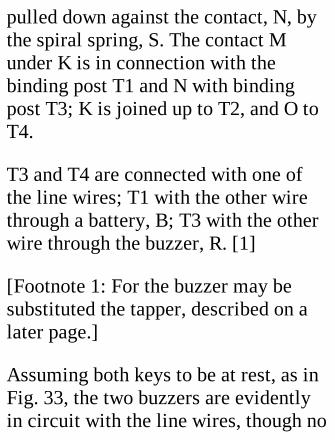
pulled down against the contact, N, bythe spiral spring, S. The contact Munder K is in connection with thebinding post T1 and N with bindingpost T3; K is joined up to T2, and O toT4.
T3 and T4 are connected with one ofthe line wires; T1 with the other wirethrough a battery, B; T3 with the otherwire through the buzzer, R. [1]
[Footnote 1: For the buzzer may besubstituted the tapper, described on alater page.]
Assuming both keys to be at rest, as inFig. 33, the two buzzers are evidentlyin circuit with the line wires, though no
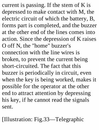
current is passing. If the stem of K isdepressed to make contact with M, theelectric circuit of which the battery, B,forms part is completed, and the buzzerat the other end of the lines comes intoaction. Since the depression of K raisesO off N, the "home" buzzer'sconnection with the line wires isbroken, to prevent the current beingshort-circuited. The fact that thisbuzzer is periodically in circuit, evenwhen the key is being worked, makes itpossible for the operator at the otherend to attract attention by depressinghis key, if he cannot read the signalssent.
[Illustration: Fig.33—Telegraphic
apparatus; sending key, buzzer andbattery]
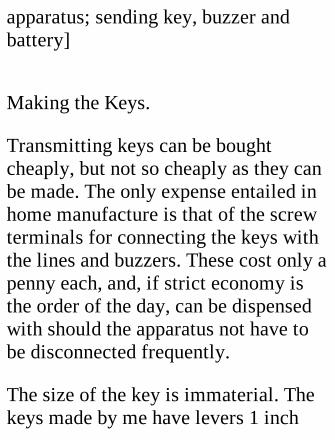
Making the Keys.
Transmitting keys can be boughtcheaply, but not so cheaply as they canbe made. The only expense entailed inhome manufacture is that of the screwterminals for connecting the keys withthe lines and buzzers. These cost only apenny each, and, if strict economy isthe order of the day, can be dispensedwith should the apparatus not have tobe disconnected frequently.
The size of the key is immaterial. Thekeys made by me have levers 1 inch
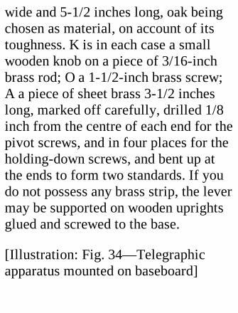
wide and 5-1/2 inches long, oak beingchosen as material, on account of itstoughness. K is in each case a smallwooden knob on a piece of 3/16-inchbrass rod; O a 1-1/2-inch brass screw;A a piece of sheet brass 3-1/2 incheslong, marked off carefully, drilled 1/8inch from the centre of each end for thepivot screws, and in four places for theholding-down screws, and bent up atthe ends to form two standards. If youdo not possess any brass strip, the levermay be supported on wooden uprightsglued and screwed to the base.
[Illustration: Fig. 34—Telegraphicapparatus mounted on baseboard]

Contact M is a small piece of brassattached to the base by a screw at oneend and by T1 at the other. K wasdrilled near the end to take the shortcoil of insulated wire joining it to T2,and O was similarly connected with T4.
The spring, S, should be fairly strong.A steel spiral with a loop at each end ismost easily fitted. Drill holes in thelever and base large enough for thespring to pass through freely, make asmall cross hole through the lever holefor a pin, and cut a slot across the basehole for a pin to hold the bottom of thespring. Adjust the lever by means ofscrew O so that there is a space ofabout 1/4-inch between K and M when
O and N are in contact, and after thespring has been put in position give thescrew a turn or two to bring K down towithin 1/16 inch of M. This will put therequired tension on the spring.
The Buzzers.—For these I selected acouple of small electric bells, costing2s. 6d. each. Their normal rate ofvibration being much too slow fortelegraphic purposes, I cut off thehammers to reduce the inertia, and soadjusted the contact screw that thearmature had to move less than onehundredth of an inch to break thecircuit. This gave so high a rate ofvibration that the key could not makeand break the circuit quickly enough to
prevent the buzzer sounding.
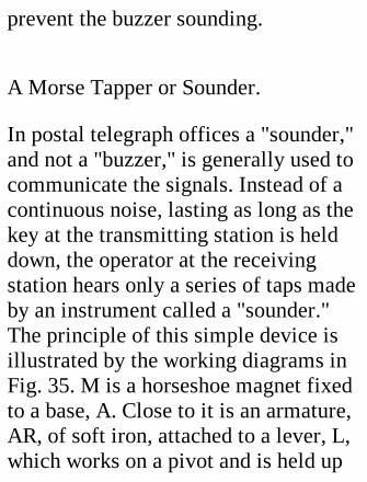
A Morse Tapper or Sounder.
In postal telegraph offices a "sounder,"and not a "buzzer," is generally used tocommunicate the signals. Instead of acontinuous noise, lasting as long as thekey at the transmitting station is helddown, the operator at the receivingstation hears only a series of taps madeby an instrument called a "sounder."The principle of this simple device isillustrated by the working diagrams inFig. 35. M is a horseshoe magnet fixedto a base, A. Close to it is an armature,AR, of soft iron, attached to a lever, L,which works on a pivot and is held up
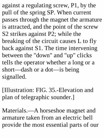
against a regulating screw, P1, by thepull of the spring SP. When currentpasses through the magnet the armatureis attracted, and the point of the screwS2 strikes against P2; while thebreaking of the circuit causes L to flyback against S1. The time interveningbetween the "down" and "up" clickstells the operator whether a long or ashort—dash or a dot—is beingsignalled.
[Illustration: FIG. 35.-Elevation andplan of telegraphic sounder.]
Materials.—A horseshoe magnet andarmature taken from an electric bellprovide the most essential parts of our
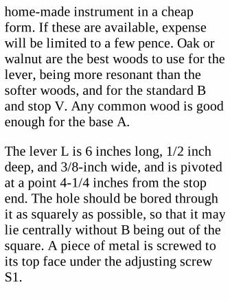
home-made instrument in a cheapform. If these are available, expensewill be limited to a few pence. Oak orwalnut are the best woods to use for thelever, being more resonant than thesofter woods, and for the standard Band stop V. Any common wood is goodenough for the base A.
The lever L is 6 inches long, 1/2 inchdeep, and 3/8-inch wide, and is pivotedat a point 4-1/4 inches from the stopend. The hole should be bored throughit as squarely as possible, so that it maylie centrally without B being out of thesquare. A piece of metal is screwed toits top face under the adjusting screwS1.

The spring is attached to L and A in themanner already described on p. 89 inconnection with the "buzzer."
The plate P2 should be stout enoughnot to spring under the impact of thelever. Fig. 36 is an end view of thestandard B. The drilling of the pivothole through this requires care. Thescrew S2 should be so adjusted as toprevent the armature actually touchingthe cores of the magnets whenattracted. The ends of the magnetwinding wire, after being scraped, areclipped tightly against the base by thebinding posts T1 T2.
If sounders are used in place of buzzers

they are connected up with the keys,batteries, and line wires in the mannershown in Fig. 33.
Batteries.
The dry cells used for electric bells arethe most convenient batteries to use.They can now be purchased at allprices from a shilling upwards, andgive about 1-1/2 volts when in goodcondition. One cell at each end willsuffice for short distances, or forconsiderable distances if largeconductors are used. If a single cellfails to work the buzzer stronglythrough the circuit, another cell mustbe added.
[Illustration: FIG. 36.—Standard forsounder.]
For ease in transport it will be foundadvisable to mount key, buzzer, andbattery on a common baseboard, whichshould be provided with a cover andhandle. The three parts areinterconnected with one another, andthe line wire terminals as sketched inFig. 34. This arrangement makes theapparatus very compact and self-contained. As a finishing touch fit thelid inside with clips for holding a stiff-backed writing pad and pencil for therecording of messages.
Lines.—Fencing made of stout
galvanized iron wires strung onwooden posts supplies excellentconductors for practice purposes,provided the posts be quite dry. In wetweather there will be leakage. (Fencingwith metal posts is, of course,unsuitable, as every post short-circuitsthe current.) The two wires selected forland lines must be scraped quite brightat the points where the connections areto be made.
It is an easy matter to rig up atelegraph line of galvanized wire 1/12to 1/8 inch in diameter, strung alonginsulators (the necks of bottles servethe purpose excellently) supported ontrees, posts, or rough poles. The length
of the line will be limited by thebattery power available, but a 6-voltbattery at each end will probablysuffice for all experimental purposes.A second wire is not needed if oneterminal at each end is connected witha copper plate sunk in the ground, orwith a metal fence, drain-pipe, etc.
XI. A RECIPROCATINGELECTRIC MOTOR.
The electric motor to be treated in thischapter illustrates very prettily theattractive force of a hollow, wire-
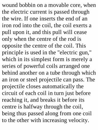
wound bobbin on a movable core, whenthe electric current is passed throughthe wire. If one inserts the end of aniron rod into the coil, the coil exerts apull upon it, and this pull will ceaseonly when the centre of the rod isopposite the centre of the coil. Thisprinciple is used in the "electric gun,"which in its simplest form is merely aseries of powerful coils arranged onebehind another on a tube through whichan iron or steel projectile can pass. Theprojectile closes automatically thecircuit of each coil in turn just beforereaching it, and breaks it before itscentre is halfway through the coil,being thus passed along from one coilto the other with increasing velocity.

Our motor is essentially a veryinefficient one, its energy being smallfor the current used, as compared witha revolving motor of the usual kind.But it has the advantage of being veryeasy to make.
[Illustration: FIG. 37.—Electricreciprocating engine and battery.]
How it works.—The experimentalengine, constructed in less than acouple of hours, which appears in Fig.38, consists of a coil, C, strapped downby a piece of tin to a wooden bedplate;a moving plunger, P, mounted on aknitting-needle slide rod, SR; a wireconnecting rod, SR; a wooden crank, K;

and a piece of knitting-needle for crankshaft, on which are mounted a smalleccentric brass wipe, W, and a coppercollar, D. Against D presses a brassbrush, B1 connected with the bindingpost, T1; while under W is a long stripof springy brass against which Wpresses during part of every revolution.T2 is connected to one end of the coilwinding, and T1 through a 4-voltaccumulator or three dry cells, with theother end of the coil. When W touchesB2 the circuit is completed, and thecoil draws in the plunger, the contactbeing broken before the plunger getshome. The crank rotates at a very highspeed if there is plenty of batterypower, all the moving parts appearing
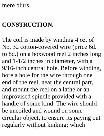
mere blurs.
CONSTRUCTION.
The coil is made by winding 4 oz. ofNo. 32 cotton-covered wire (price 6d.to 8d.) on a boxwood reel 2 inches longand 1-1/2 inches in diameter, with a9/16-inch central hole. Before winding,bore a hole for the wire through oneend of the reel, near the central part,and mount the reel on a lathe or animprovised spindle provided with ahandle of some kind. The wire shouldbe uncoiled and wound on somecircular object, to ensure its paying outregularly without kinking; which

makes neat winding almost impossible.
Draw a foot of the wire through thehole in the reel, and drive in a tiny peg—which must not protrude inwards—to prevent it slipping. Lay the turns oncarefully, forcing them into closecontact, so that the next layer may havea level bed. On reaching the end of thelayer, be equally careful to finish itneatly before starting back again.When the wire is all on, bore a hole asnear the edge of the finishing edge aspossible, and draw the spare wirethrough. Then cut a strip of tough paperof the width of the coils, coat one sidewith paste, and wrap it tightly roundthe outside to keep the wire in place.

Note.—Insulation will be improved ifevery layer of wire is painted over withshellac dissolved in alcohol before thenext layer is applied.
Flatten the reel slightly with a file atthe points of contact with thebaseboard, to prevent rolling.
The plunger is a tube of thin iron, 1/16inch less in diameter than the hole inthe reel, and 1/4 inch longer than thereel. If a ready-made tube is notavailable, construct one by twisting apiece of tin round a metal rod, andsoldering the joint. As it is difficult tomake a jointed tube cylindrical, and aclose fit is needed to give good results,
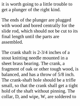
it is worth going to a little trouble toget a plunger of the right kind.
The ends of the plunger are pluggedwith wood and bored centrally for theslide rod, which should not be cut to itsfinal length until the parts areassembled.
The crank shaft is 2-3/4 inches of astout knitting needle mounted in asheet brass bearing. The crank, afragment of oak or other tough wood, isbalanced, and has a throw of 5/8 inch.The crank-shaft hole should be a triflesmall, so that the crank shall get a tighthold of the shaft without pinning. Thecollar, D, and wipe, W, are soldered to
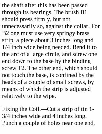
the shaft after this has been passedthrough its bearings. The brush B1should press firmly, but notunnecessarily so, against the collar. ForB2 one must use very springy brassstrip, a piece about 3 inches long and1/4 inch wide being needed. Bend it tothe arc of a large circle, and screw oneend down to the base by the bindingscrew T2. The other end, which shouldnot touch the base, is confined by theheads of a couple of small screws, bymeans of which the strip is adjustedrelatively to the wipe.
Fixing the Coil.—Cut a strip of tin 1-3/4 inches wide and 4 inches long.Punch a couple of holes near one end,
and nail this to the side of the base,with its forward end 4-1/4 inches fromthe crank shaft. Pass the strip over thecoil, and bend it down towards thebase. Drill a couple of screw holes, andscrew the other end down so that thecoil is gripped fairly tight.
Fixing the Plunger. Two small guides,G1 G2, are made for the plunger. Theholes through which the slide rodmoves should be a good fit, and theircentres at the level of the centre of thecoil. Screw holes are bored in the feet.
Pass the plunger through the coil, andplace the guides on the rod. Then drawthe plunger forward till 1/2 inch
projects. Bring G1 close up to it, markits position, and screw it to the base.The other guide, G2, should be 1-1/2inches away from the rear of the coil.
[Illustration: Fig. 38.—Plan of electricreciprocating engine.]
The coil and guides must be adjustedso that the plunger does not touch thecoil anywhere during a stroke, packingsbeing placed, if necessary, under coilor guides. When the adjustment issatisfactory, screw the coil downtightly, and cut off any superfluousparts of the rod.
The Connecting Rod.—Bore a holenear the end of the plunger for a screw
to hold the rear end of the connectingrod. Pull the plunger out till 1-3/4inches project, turn the crank fullforward, and measure off the distancebetween the centres of the plunger holeand the crank pin. Drive a couple ofwire nails into a board, and twist theends of a piece of 1/20-inch wire roundthem twice. This wire constitutes aconnecting rod amply strong enough tostand the pulls to which it will besubjected. Fix the rod in position.
Adjusting the Wipe.—Turn the wipe,W, round until it makes contact withB2, and, holding the crank shaft with apair of pliers, twist the crank on it till itjust begins the return stroke. Then turn
the crank to find out how long the wiperemains in contact, and adjust the crankrelatively to the wipe so that the crankis vertical when the period of contact ishalf finished. The length of this periodis controlled by the set screws at thefree end of B2.
OTHER DETAILS.
The fly wheel may be a disc of wood.
Oil all the rubbing parts slightly.Connect T1 to one terminal of thebattery, T2 to the coil, and the otherterminal of the battery to the coil. Setthe engine going. If it refuses to run,

make sure that B1 is pressing againstD. The speed of the engine maypossibly be improved by carefuladjustment of B2 and an alteration inthe setting of the crank, and willcertainly be accelerated by increasingthe number of battery cells.
The cost of the engine described wasabout 1s, 3d., exclusive of the battery.
XII. AN ELECTRICALARM CLOCK.
Anybody who possesses an alarm clock

with an external gong, an electric bell,and a battery, may easily make themcombine to get the drowsiest of mortalsout of bed on the chilliest of wintermornings. The arrangement has as itssecondary advantages and capabilities—
(l) That the clock can be placed whereits ticking will not disturb the personwhom it has to arouse in due course(some of the cheaper clocks are veryself-advertising);
(2) That one clock can be made tooperate any number of bells indifferent parts of the house.
The main problem to be solved is, how
to make the alarm mechanism of theclock complete an electric circuit whenthe alarm "goes off."
If you examine an alarm clock of thetype described, you will find that thegong hammer lies against the gongwhen at rest, and that its shaft when inmotion vibrates to and fro about aquarter of an inch.
[Illustration: FIG. 89.—Plan of releasegear of electric alarm, as attached toclock.]
Fig. 39 shows a. method of utilizing themovement of the hammer. A piece ofwood, 2 inches long, wide enough tofill the space between the rear edge of

the clock and the hammer slot, and 1/2inch thick, has its under side hollowedout to the curvature of the clock barrel.This block serves as a base for twobinding posts or terminals, T1 T2. Avertical slit is made in T1 and in this issoldered [to] one end of a little piece ofspring brass strip, 1 inch long and 1/4inch wide. To the back of the other endof the strip solder a piece of 1/20 inchwire, projecting l inch below the strip.The strip must be bent so that it pressesnaturally against T2. A little trigger, B,which you can cut out of sheet brass, ispivoted at a, where it must be raised offthe base by a small washer. It projects1/4 inch beyond the base on the gongsupport side. A square nick is cut in it
at such a distance from a that, when thewire spike on C is in the nick, the stripis held clear of T2. The other end of thetrigger, when the trigger is set, must be1/8 inch from the shank of the alarmhammer—at any rate not so far awaythat the hammer, when it vibrates,cannot release C from the nick.
To fix the base on to the top of theclock, the works must be removed(quite an easy matter to accomplish)and holes bored for a couple of screwsput through from the inside. If theunderside of the base is not quitecorrectly curved, take care not to forcein the screws far enough to distort thebarrel. It is advisable to do the fitting
of the parts of the release after the basehas been fixed, and before the worksare replaced. The position of thehammer shaft can be gauged accuratelyenough from the slot in the case.
The tails of the terminals T1 T2 mustbe truncated sufficiently not topenetrate the base and make contactwith the barrel, or a "short circuit" willbe evident as soon as the battery isconnected up.
[Illustration: Fig. 40.—Electric alarmreleaser, as attached to separatewooden clock casing.]
If the bell, battery, and clock are in thesame room, a single dry cell will give
sufficient current; but if the circuit is along one, or several bells have to beoperated, two or more cells will berequired.
An Alternative Arrangement.—Shouldthe reader prefer to have the clockquite free from the release—and this iscertainly convenient for winding andsetting the alarm—he should make alittle wooden case for the clock tostand in, just wide enough to take theclock, and the back just as high as thetop of the barrel. The release is thenattached to a little platform projectingfrom the back, care being taken that thelever is arranged in the correct positionrelatively to the hammer when the

clock is pushed back as far as it will go(Fig. 40).
If a self-contained outfit is desired,make the case two-storied: the upperdivision for the clock, the lower for thecell or cells. The bell may be attachedto the front. A hinged fretwork front tothe clock chamber, with an opening thesize of the face; a door at the back ofthe cell chamber; and a general neatfinish, staining and polishing, arerefinements that some readers may liketo undertake.
Setting the Alarm.—A good manyalarm clocks are not to be relied uponto act within a quarter of an hour or so
of the time to which they are set. Butabsolute accuracy of working may beobtained if the clock hands are first setto the desired hour, and the alarm dialhand revolved slowly till the alarm isreleased. The hands are then set at thecorrect time, and the alarm fullywound.
XIII. A MODELELECTRIC RAILWAY.
The rapid increase in the number ofelectrically worked railways, and thesubstitution of the electric for the
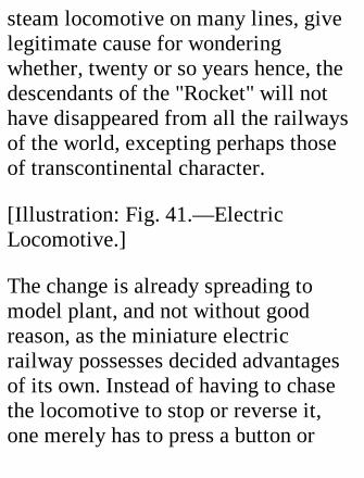
steam locomotive on many lines, givelegitimate cause for wonderingwhether, twenty or so years hence, thedescendants of the "Rocket" will nothave disappeared from all the railwaysof the world, excepting perhaps thoseof transcontinental character.
[Illustration: Fig. 41.—ElectricLocomotive.]
The change is already spreading tomodel plant, and not without goodreason, as the miniature electricrailway possesses decided advantagesof its own. Instead of having to chasethe locomotive to stop or reverse it,one merely has to press a button or
move a switch. The fascinations of amodel steam locomotive, with itsfurnace, hissing of steam, business-likepuffings, and a visible working ofpiston and connecting rods, are not tobe denied, any more than that a full-sized steam locomotive is a moreimposing object at rest or in motionthan its electric rival. On the otherhand, the ease of control alreadynoticed, and the absence of burningfuel, water leakage, smoke and fumes,are strong points in favour of theelectric track, which does no moreharm to a carpet than to a front lawn,being essentially clean to handle.Under the head of cost the electriclocomotive comes out well, as motors
can be purchased cheaply; andconnecting them up with drivingwheels is a much less troublesomebusiness than the construction of anequally efficient steamer. One may addthat the electric motor is ready to startat a moment's notice: there is no delaycorresponding to that caused by theraising of steam.
The Track
We will consider this first, as its designmust govern, within certain limits, thedesign of the locomotive. There arethree systems of electrical transmissionavailable.
1. The trolley system, with overheadcable attached to insulators on posts, tocarry the current one way, the railsbeing used as the "return." This systemhas the disadvantages associated with awire over which the human foot mayeasily trip with disastrous effect.
2. That in which one of the wheel railsis used for taking the current to themotor, and the other as the return. Theobjection to the system is that thewheels must be insulated, to preventshort circuiting; and this, besidescausing trouble in construction, makesit impossible to use the ordinary modelrolling stock. To its credit one mayplace the fact that only two rails are
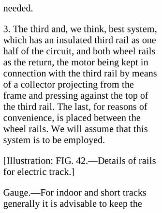
needed.
3. The third and, we think, best system,which has an insulated third rail as onehalf of the circuit, and both wheel railsas the return, the motor being kept inconnection with the third rail by meansof a collector projecting from theframe and pressing against the top ofthe third rail. The last, for reasons ofconvenience, is placed between thewheel rails. We will assume that thissystem is to be employed.
[Illustration: FIG. 42.—Details of railsfor electric track.]
Gauge.—For indoor and short tracksgenerally it is advisable to keep the
gauge narrow, so that sharp curves maybe employed without causing unduefriction between rails and wheels. Inthe present instance we specify a 2-inch gauge, for which, as also for 1-1/2and 1-1/4 inch, standard rolling stock issupplied by the manufacturers.
Track Construction.—It is essentialthat the centre rail and at least one ofthe wheel rails shall have all jointsbonded together to give a clear courseto the electric current, and the centrerail must be insulated to preventleakage and short-circuiting. Where atrack is laid down more or lesspermanently, the bonding is mostpositively effected by means of little
fish-plates, screwed into the sides ofthe abutting rails; but in the case of atrack which must be capable of quickcoupling-up and uncoupling, some sucharrangement as that shown in Fig. 42 isto be recommended.
Fig. 42 (a) is a cross vertical section ofthe track; Fig. 42 (c) a longitudinalview; while Fig. 42 (b) shows in plan apoint of junction of two lengths of rail.
The wheel rails are made of carefullystraightened brass strip 3/8 inch wideand 1/16 inch thick, sunk rather morethan 1/8 inch into wooden sleepers(Fig. 42, a), 3-1/2 inches long and 3/4inch wide (except at junctions). The
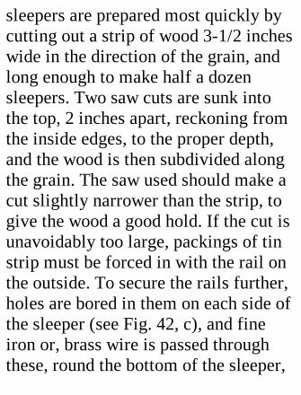
sleepers are prepared most quickly bycutting out a strip of wood 3-1/2 incheswide in the direction of the grain, andlong enough to make half a dozensleepers. Two saw cuts are sunk intothe top, 2 inches apart, reckoning fromthe inside edges, to the proper depth,and the wood is then subdivided alongthe grain. The saw used should make acut slightly narrower than the strip, togive the wood a good hold. If the cut isunavoidably too large, packings of tinstrip must be forced in with the rail onthe outside. To secure the rails further,holes are bored in them on each side ofthe sleeper (see Fig. 42, c), and fineiron or, brass wire is passed throughthese, round the bottom of the sleeper,
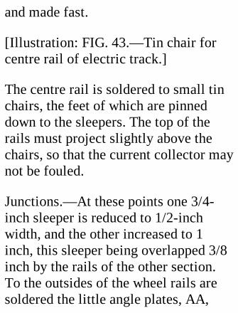
and made fast.
[Illustration: FIG. 43.—Tin chair forcentre rail of electric track.]
The centre rail is soldered to small tinchairs, the feet of which are pinneddown to the sleepers. The top of therails must project slightly above thechairs, so that the current collector maynot be fouled.
Junctions.—At these points one 3/4-inch sleeper is reduced to 1/2-inchwidth, and the other increased to 1inch, this sleeper being overlapped 3/8inch by the rails of the other section.To the outsides of the wheel rails aresoldered the little angle plates, AA,
BB, attached to the sleepers by brasstacks, which project sufficiently to takethe brass wire hooks. These hooks mustbe of the right length to pull upon thetacks in AA and make a good contact.The centre rails are bonded by twostrips of springy brass, riveted to onesection, and forced apart at their freeend by the interposed strip. Two pinsprojecting from the narrower sleeper fitinto holes in the wider to keep thesections in line at a junction.
General.—The sleepers of straightsections are screwed down to 3/4 by1/4 inch longitudinals, which help tokeep the track straight and prevent thesleepers slipping. Sections should be of
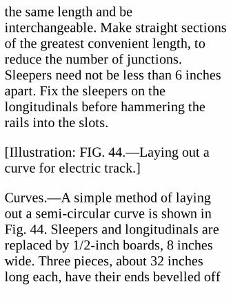
the same length and beinterchangeable. Make straight sectionsof the greatest convenient length, toreduce the number of junctions.Sleepers need not be less than 6 inchesapart. Fix the sleepers on thelongitudinals before hammering therails into the slots.
[Illustration: FIG. 44.—Laying out acurve for electric track.]
Curves.—A simple method of layingout a semi-circular curve is shown inFig. 44. Sleepers and longitudinals arereplaced by 1/2-inch boards, 8 incheswide. Three pieces, about 32 incheslong each, have their ends bevelled off
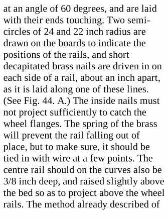
at an angle of 60 degrees, and are laidwith their ends touching. Two semi-circles of 24 and 22 inch radius aredrawn on the boards to indicate thepositions of the rails, and shortdecapitated brass nails are driven in oneach side of a rail, about an inch apart,as it is laid along one of these lines.(See Fig. 44. A.) The inside nails mustnot project sufficiently to catch thewheel flanges. The spring of the brasswill prevent the rail falling out ofplace, but to make sure, it should betied in with wire at a few points. Thecentre rail should on the curves also be3/8 inch deep, and raised slightly abovethe bed so as to project above the wheelrails. The method already described of
bonding at joints will serve equallywell on curves. If the outer rail issuper-elevated slightly, there will beless tendency for the rolling stock tojump the track when rounding thecurve.
When the rails are in place the boardsmay be cut with a pad-saw to curvescorresponding with the breadth of thetrack on the straight. If the boardsincline to warp, screw some pieces of1/8-inch strip iron to the under sideacross the grain, sinking the iron inflush with the wood.
The brass strip for the rails costs aboutone penny per foot run. Iron strip is

much cheaper, but if it rusts, as it isvery likely to do, the contact placeswill need constant brightening.
Points.—Fig. 45 shows the manner oflaying out a set of points, andconnecting up the rails. The outsidewheel rails, it will be seen, arecontinuous, and switching is effectedby altering the position of the movingtongues, pivoted at PP, by means of therod R, which passes through a hole inthe continuous rail to a lever or motorof the same reversible type as is usedfor the locomotive. If a motor isemployed, R should be joined to acrank pin on the large driven cog—corresponding to that affixed to the
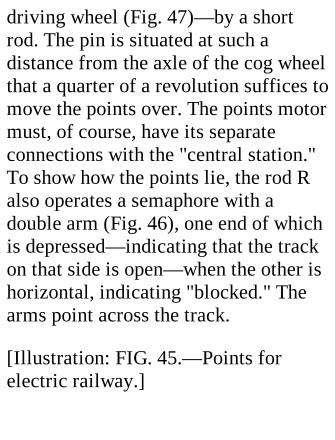
driving wheel (Fig. 47)—by a shortrod. The pin is situated at such adistance from the axle of the cog wheelthat a quarter of a revolution suffices tomove the points over. The points motormust, of course, have its separateconnections with the "central station."To show how the points lie, the rod Ralso operates a semaphore with adouble arm (Fig. 46), one end of whichis depressed—indicating that the trackon that side is open—when the other ishorizontal, indicating "blocked." Thearms point across the track.
[Illustration: FIG. 45.—Points forelectric railway.]
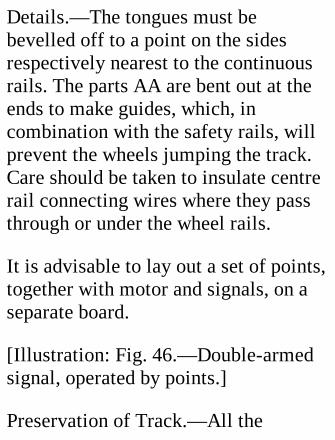
Details.—The tongues must bebevelled off to a point on the sidesrespectively nearest to the continuousrails. The parts AA are bent out at theends to make guides, which, incombination with the safety rails, willprevent the wheels jumping the track.Care should be taken to insulate centrerail connecting wires where they passthrough or under the wheel rails.
It is advisable to lay out a set of points,together with motor and signals, on aseparate board.
[Illustration: Fig. 46.—Double-armedsignal, operated by points.]
Preservation of Track.—All the

wooden parts of an outdoor trackshould be well creosoted before use.
The Electric Locomotive.
An elevation and a plan of this aregiven in Fig. 47. The two pairs ofwheels are set close together, so thatthey may pass easily round curves.
[Illustration: Fig. 47.—Plan andelevation of electric locomotive.]
The Motor.—A motor of ordinary type,with electro field magnets, isunsuitable for traction, as it cannot bereversed by changing the direction ofthe current, unless a special and rather
expensive type of automatic switch beused. While a motor of this kind is, inconjunction with such a switch, themost efficient, the motor withpermanent field magnets is preferableas regards cost and ease of fixing. Itcan be reversed through the rails. Thearmature or revolving part must betripolar to be self-starting in allpositions.
A motor of sufficient power can bebought for half a crown or less—in anycase more cheaply than it can be madeby the average amateur.
The motor used for the locomotiveillustrated was taken to pieces, and the

magnet M screwed to a strip of wood1-5/8 inches wide; and for the originalarmature bearings were substituted acouple of pieces of brass strip, HH,screwed to two wooden supports, SS,on the base, E (Fig. 47, a). It was foundnecessary to push the armature alongthe spindle close to the commutatorpiece, C, and to shorten the spindle atthe armature end and turn it down tothe size of the original bearing, in orderto bring the motor within the spacebetween the wheels.
The place of the small pulley was takenby an 8-toothed pinion wheel, engagingwith a pinion soldered to the neardriving wheel, the diameter of which it
exceeded by about 3/16 inch. The pair,originally parts of an old clockpurchased for a few pence, gave agearing-down of about 9 times.
The position of the driven wheelsrelatively to the armature must befound experimentally. There is plentyof scope for adjustment, as the wheelscan be shifted in either directionlongitudinally, while the distancebetween wheel and armature centresmay be further modified in the lengthof the bearings, BE. These last arepieces of brass strip turned up at theends, and bored for axles, and screwedto the under side of the base. Toprevent the axles sliding sideways and
the wheels rubbing the frame, soldersmall collars to them in contact withthe inner side of the bearings.
The Frame.—Having got the motorwheels adjusted, shorten E so that itprojects 2 inches beyond the centres ofthe axles at each end. Two cross bars,GG, 3-1/2 inches long, are then gluedto the under side of E, projecting 1/8inch. To these are glued two 3/8-inchstrips, FF, of the same length as E. Abuffer beam, K, is screwed to G. Aremovable cover, abedfg, is made outof cigar-box wood or tin. The ends reston GG; the sides on FF. Doors andwindows are cut out, and handrails,etc., added to make the locomotive
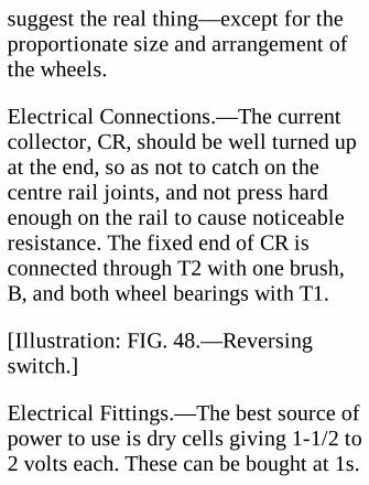
suggest the real thing—except for theproportionate size and arrangement ofthe wheels.
Electrical Connections.—The currentcollector, CR, should be well turned upat the end, so as not to catch on thecentre rail joints, and not press hardenough on the rail to cause noticeableresistance. The fixed end of CR isconnected through T2 with one brush,B, and both wheel bearings with T1.
[Illustration: FIG. 48.—Reversingswitch.]
Electrical Fittings.—The best source ofpower to use is dry cells giving 1-1/2 to2 volts each. These can be bought at 1s.
apiece in fairly large sizes. Four or fiveconnected in series will work quite along line if the contacts are in goodcondition.
A reversing switch is needed to alterthe direction of the current flow. Theconstruction of one is an exceedinglysimple matter. Fig. 48 gives a plan ofswitch and connection, from which theprinciple of the apparatus will begathered. The two links, LL, are thinspringy brass strips slightly curved,and at the rear end pivoted on thebinding posts T1 T2. Underneath theother ends solder the heads of a coupleof brass nails. The links are heldparallel to one another by a wooden
yoke, from the centre of which projectsa handle. The three contacts C1 C2 C3must be the same distance apart as thecentres of the link heads, and sosituated as to lie on the arcs of circlesdescribed by the links. The bindingpost T3 is connected with the twooutside contacts—which may be flat-headed brass nails driven in almostflush with the top of the wooden base—by wires lying in grooves under thebase, and T4 with the central contact.As shown, the switch is in the neutralposition and the circuit broken.
[Illustration: Fig. 49.—Multiplebattery switch.]
Multiple Battery Switch.—To controlthe speed of the train and economizecurrent a multiple battery switch isuseful. Fig. 49 explains how to makeand connect up such a switch. Thecontacts, C1 to C5, lie in the path of theswitch lever, and are connected throughbinding posts T1 to T6 with oneterminal of their respective cells. Thecells are coupled up in series to oneanother, and one terminal of the serieswith binding posts T0 and T6. Bymoving the lever, any number of thecells can be put in circuit with T7. Thebutton under the head of the levershould not be wide enough to bridgethe space between any two contacts.Change the order of the cells
occasionally to equalize theexhaustion.
[Illustration: FIG. 50.—Adjustableresistance for controlling current.]
Resistance.—With accumulators, a"resistance" should be included in thecircuit to regulate the flow of current.The resistance shown in Fig. 50consists of a spiral of fine Germansilver wire lying in the groovedcircumference of a wood disc. One ofthe binding posts is in connection withthe regulating lever pivot, the otherwith one end of the coil. By moving thelever along the coil the amount ofGerman silver wire, which offers
resistance to the current, is altered.When starting the motor use as littlecurrent as possible, and open theresistance as it gets up speed, chokingdown again when the necessary speedis attained.
General.—All the three fittingsdescribed should for convenience bemounted on the same board, whichitself may form the cover of the boxholding the dry cells or accumulators.
SOME SUGGESTIONS.
Instead of dry cells or accumulators asmall foot or hand operated dynamo
generating direct, not alternatingcurrent, might be used. Its life isindefinitely long, whereas dry cellsbecome exhausted with use, andaccumulators need recharging fromtime to time. On occasion such adynamo might prove very convenient.
Anyone who possesses a fair-sizedstationary engine and boiler mightincrease the realism of the outdoortrack by setting up a generating station,which will give a good deal of extrafun.
XIV. A SIMPLE
RECIPROCATINGENGINE.
Figs. 51 and 52 illustrate a very simpleform of fixed-cylinder enginecontrolled by a slide valve.
An open-ended "trunk" piston, similarin principle to that used in gas engines,is employed; and the valve is of thepiston type, which is less complicatedthan the box form of valve, though lesseasily made steam-tight in small sizes.The engine is single-acting, makingonly one power stroke per revolution.
The cylinder is a piece of brass tubing;the piston another piece of tubing,
fitting the first telescopically. Providedthat the fit is true enough to prevent theescape of steam, while not so close asto set up excessive friction, a packingbehind the piston is not needed; butshould serious leakage be anticipated, apacking of thick felt or cloth, held upby a washer and nuts on the gudgeon G,will make things secure. Similarly forthe built-up piston valve P may besubstituted a piece of close-fittingbrass rod with diameter reduced,except at the ends, by filing or turning,to allow the passage of steam.
CONSTRUCTION.
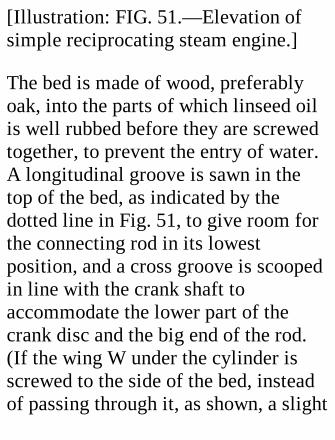
[Illustration: FIG. 51.—Elevation ofsimple reciprocating steam engine.]
The bed is made of wood, preferablyoak, into the parts of which linseed oilis well rubbed before they are screwedtogether, to prevent the entry of water.A longitudinal groove is sawn in thetop of the bed, as indicated by thedotted line in Fig. 51, to give room forthe connecting rod in its lowestposition, and a cross groove is scoopedin line with the crank shaft toaccommodate the lower part of thecrank disc and the big end of the rod.(If the wing W under the cylinder isscrewed to the side of the bed, insteadof passing through it, as shown, a slight
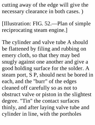
cutting away of the edge will give thenecessary clearance in both cases. )
[Illustration: FIG. 52.—Plan of simplereciprocating steam engine.]
The cylinder and valve tube A shouldbe flattened by filing and rubbing onemery cloth, so that they may bedsnugly against one another and give agood holding surface for the solder. Asteam port, S P, should next be bored ineach, and the "burr" of the edgescleaned off carefully so as not toobstruct valve or piston in the slightestdegree. "Tin" the contact surfacesthinly, and after laying valve tube andcylinder in line, with the portholes
corresponding exactly, bind themtightly together with a turn or two ofwire, or hold them lightly in a vice,while the solder is made to run againwith the aid of a spirit lamp. If it seemsnecessary, run a little extra solderalong the joint, both sides, and at theends.
The valve, if built up, consists of acentral rod, threaded at the rear end,four washers which fit the tube, and acentral spacing-piece. The forwardwasher is soldered to the rod. Behindthis is placed a felt packing. Then comein order the central spacing-piece, witha washer soldered to each end, a secondpacking, and a fourth washer. The
series is completed by an adjusting nutto squeeze the packings, and a lock nutto prevent slipping. The back end of thevalve must be wide enough to justmore than cover the steam port. If thefelt proves difficult to procure or fit,one may use a ring or two of brasstubing, with an external packing ofasbestos cord.
The cylinder wing W should have thetop edge turned over for an eighth of aninch or so to give a good bearingagainst the cylinder, and be held inposition by a wire while the solderingis done. It is important that the line ofthe wing should be at right angles to aline passing through the centres of the
valve tube and cylinder.
Shaft Bearings.—Take a piece of stripbrass half an inch or so wide and 3-1/2inches long. Bore four holes for screws,and scratch cross lines an inch fromeach extremity. Turn up the ends atthese lines at right angles to the centralpart, stand the piece on some flatsurface, and on the outer faces of theuprights scratch two cross lines at theheight of the centre of the cylinderabove the bed. Mark the central pointsof these lines.
Next select a piece of brass tubingwhich fits the rod chosen for the crankshaft, and bore in the bearing standards
two holes to fit this tubing. Slip thetubing through the standards and solderit to them. The ends and central partsof the tubing must now be so cut awayas to leave two bearings, BB—that atthe fly-wheel end projecting far enoughto allow the fly wheel, when brought upagainst it, to just clear the bed; that atthe crank end being of the properlength to allow the eccentric to be inline with the valve rod, and the crankdisc to occupy its proper positionrelatively to the central line of thecylinder. Finish off the standards byfiling the tops concentrically with thebearings.
The eccentric may be built up from a
metal disc about 3/4 inch diameter andtwo slightly larger discs solderedconcentrically to the sides. The widthof the middle disc should be the sameas that of the eccentric rod. A carefulfiler could make a passable eccentricby sinking a square or semicirculargroove in the edge of a wide disc. Thecentre of the eccentric must be foundcarefully, and a point marked at adistance from it equal to half the travelof the valve. To ascertain this, pull thevalve forward until the steam port isfully exposed, insert a bar at the rearend of the valve tube, and mark it.Then push the valve back until a wirepushed through the port from thecylinder side shows that the port is
again fully exposed. Insert and markthe bar again. The distance between themarks gives you the "travel" required.
Order of Assembly.—The followinglist of operations in their order mayassist the beginner:
Make the bed.
Cut out cylinder barrel, piston, andvalve tube.
Bevel off the ends of the last inside toallow the valve to enter easily.
Make the valve.

Bore the steam ports, and solder valvetube and cylinder together.
Solder holding-down wing, W, tocylinder.
Finish off the piston.
Solder the bearings in their standards.
Prepare shaft, crank disc, crank pin,and piston rod.
Fix the cylinder to the bed, in which aslot must be cut for the wing andholding-down bolt.
Attach the piston rod to the piston, andinsert piston in cylinder.
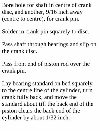
Bore hole for shaft in centre of crankdisc, and another, 9/16 inch away(centre to centre), for crank pin.
Solder in crank pin squarely to disc.
Pass shaft through bearings and slip onthe crank disc.
Pass front end of piston rod over thecrank pin.
Lay bearing standard on bed squarelyto the centre line of the cylinder, turncrank fully back, and move thestandard about till the back end of thepiston clears the back end of thecylinder by about 1/32 inch.
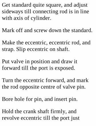
Get standard quite square, and adjustsideways till connecting rod is in linewith axis of cylinder.
Mark off and screw down the standard.
Make the eccentric, eccentric rod, andstrap. Slip eccentric on shaft.
Put valve in position and draw itforward till the port is exposed.
Turn the eccentric forward, and markthe rod opposite centre of valve pin.
Bore hole for pin, and insert pin.
Hold the crank shaft firmly, andrevolve eccentric till the port just
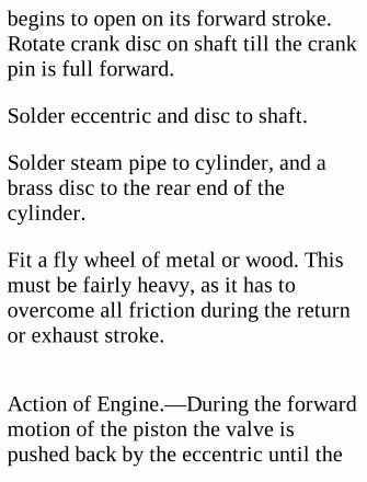
begins to open on its forward stroke.Rotate crank disc on shaft till the crankpin is full forward.
Solder eccentric and disc to shaft.
Solder steam pipe to cylinder, and abrass disc to the rear end of thecylinder.
Fit a fly wheel of metal or wood. Thismust be fairly heavy, as it has toovercome all friction during the returnor exhaust stroke.
Action of Engine.—During the forwardmotion of the piston the valve ispushed back by the eccentric until the
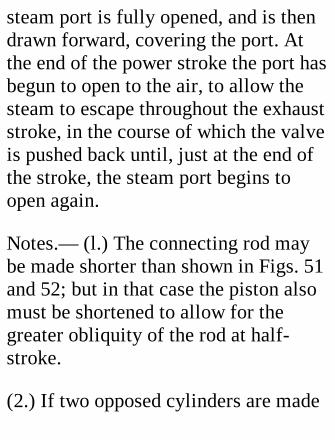
steam port is fully opened, and is thendrawn forward, covering the port. Atthe end of the power stroke the port hasbegun to open to the air, to allow thesteam to escape throughout the exhauststroke, in the course of which the valveis pushed back until, just at the end ofthe stroke, the steam port begins toopen again.
Notes.— (l.) The connecting rod maybe made shorter than shown in Figs. 51and 52; but in that case the piston alsomust be shortened to allow for thegreater obliquity of the rod at half-stroke.
(2.) If two opposed cylinders are made

to operate the one crank, a double-acting engine is obtained. Both valvesmay be operated by a single eccentric,the connecting rod of one being pivotedto a small lug projecting from theeccentric strap. If three cylinders areset 120 degrees apart round the crankshaft, a continuous turning effect isgiven. This type will be found usefulfor running small dynamos.
(3.) If it is desired to use the exhauststeam to promote a draught in theboiler furnace, it should be led away bya small pipe from the rear end of thevalve tube.
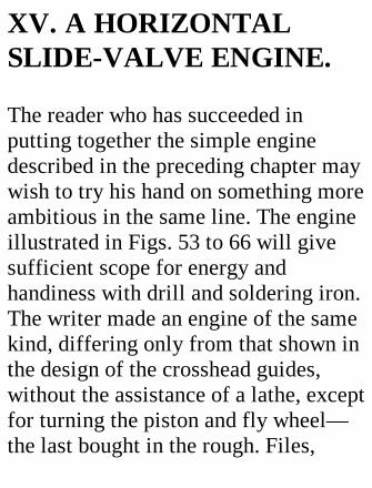
XV. A HORIZONTALSLIDE-VALVE ENGINE.
The reader who has succeeded inputting together the simple enginedescribed in the preceding chapter maywish to try his hand on something moreambitious in the same line. The engineillustrated in Figs. 53 to 66 will givesufficient scope for energy andhandiness with drill and soldering iron.The writer made an engine of the samekind, differing only from that shown inthe design of the crosshead guides,without the assistance of a lathe, exceptfor turning the piston and fly wheel—the last bought in the rough. Files,
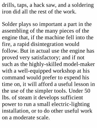
drills, taps, a hack saw, and a solderingiron did all the rest of the work.
Solder plays so important a part in theassembling of the many pieces of theengine that, if the machine fell into thefire, a rapid disintegration wouldfollow. But in actual use the engine hasproved very satisfactory; and if notsuch as the highly-skilled model-makerwith a well-equipped workshop at hiscommand would prefer to expend histime on, it will afford a useful lesson inthe use of the simpler tools. Under 50lbs. of steam it develops sufficientpower to run a small electric-lightinginstallation, or to do other useful workon a moderate scale.

[Illustration: Fig. 53.—Elevation of alarge horizontal engine.]
The principal dimensions of the engineare as follows:
Bedplate (sheet zinc), 13-1/2 incheslong; 4-1/2 inches wide; 1/8 inch thick.
Support of bedplate (1/20 inch zinc), 3inches high from wooden base tounderside of bedplate.
Cylinder (mandrel-drawn brass tubing),1-1/2 inches internal diameter; 2-13/16inches long over all.
Piston, 1-1/2 inches diameter; 1/2 inch
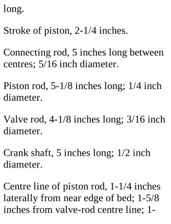
long.
Stroke of piston, 2-1/4 inches.
Connecting rod, 5 inches long betweencentres; 5/16 inch diameter.
Piston rod, 5-1/8 inches long; 1/4 inchdiameter.
Valve rod, 4-1/8 inches long; 3/16 inchdiameter.
Crank shaft, 5 inches long; 1/2 inchdiameter.
Centre line of piston rod, 1-1/4 incheslaterally from near edge of bed; 1-5/8inches from valve-rod centre line; 1-
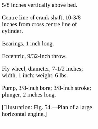
5/8 inches vertically above bed.
Centre line of crank shaft, 10-3/8inches from cross centre line ofcylinder.
Bearings, 1 inch long.
Eccentric, 9/32-inch throw.
Fly wheel, diameter, 7-1/2 inches;width, 1 inch; weight, 6 lbs.
Pump, 3/8-inch bore; 3/8-inch stroke;plunger, 2 inches long.
[Illustration: Fig. 54.—Plan of a largehorizontal engine.]

Other dimensions will be gatheredfrom the various diagrams of details.
The reader will, of course, suit his ownfancy in following these dimensions, orin working to them on a reduced scale,or in modifying details where heconsiders he can effect his object in asimpler manner.
The diagrams are sufficiently explicitto render it unnecessary to describe themaking of the engine from start tofinish, so remarks will be limited tothose points which require most carefulconstruction and adjustment.
[Illustration: Fig. 55.—Standards of

Bedplate.]
The Bedplate.—This should beaccurately squared and mounted on itsfour arch-like supports. (Fordimensions, consult Fig. 55.) Half aninch is allowed top and bottom for theturnovers by which the supports arescrewed to the bedplate and base. Theends of the longer supports are turnedback so as to lie in front of the endsupports, to which they may beattached by screws or solder, after allfour parts have been screwed to thebed. Care must be taken that the partsall have the same height. Drill all holesin the turnovers before bending. Use1/8-inch screws. Turn the bed bottom
upwards, and stand the four supports,temporarily assembled, on it upsidedown and in their correct positions, andmark off for the 3/32-inch holes to bedrilled in the bed. A hole 3/4 inch indiameter should be cut in the bedplatefor the exhaust pipe, round a centre 2inches from the end and 1-5/8 inchesfrom the edge on the fly-wheel side,and two more holes for the pump.
Making the Cylinder Slide and Valve.—The cylinder barrel must be perfectlycylindrical and free from any dents.Mandrel-drawn brass tubing, 1/16-inchthick, may be selected. If you cannotget this turned off at the ends in a lathe,mark the lines round it for working to
with the aid of a perfectly straightedged strip of paper, 2-13/16 incheswide, rolled twice round the tube. Thecoils must lie exactly under oneanother. Make plain scratches at eachend of the paper with a sharp steelpoint. Cut off at a distance of 1/16-inchfrom the lines, and work up to the lineswith a file, finishing by rubbing theends on a piece of emery cloth restingon a hard, true surface.
[Illustration: FIG. 56.-Cylinderstandard before being bent.]
A square-cornered notch 1/8 inch deepand 7/8 inch wide must now be cut ineach end of the barrel, the two notches
being exactly in line with one another.These are to admit steam from thesteam ways into the cylinder.
Cylinder Standards.-Use 5/64 or 3/32inch brass plate for these. Two piecesof the dimensions shown in Fig. 56 areneeded. Scratch a line exactly down themiddle of each, and a cross line 1/2inch from one end. The other endshould be marked, cut, and filed to asemicircle. Drill three 3/16-inch holesin the turnover for the holding-downscrews. The two standards should nowbe soldered temporarily together at theround ends and trued up to match eachother exactly. Place them in the vicewith the bending lines exactly level
with the jaws, split the turnovers apart,and hammer them over at right anglesto the main parts. Whether this hasbeen done correctly may be tested byplacing the standards on a flat surface.Take the standards apart, and scratch across line on each 1-5/8 inch from thelower surface of the foot on the sideaway from the foot. Make a punchmark where the line crosses the verticalline previously drawn, and with this ascentre describe a circle of the diameterof the outside of the barrel. Cut out theinside and file carefully up to thecircle, stopping when the barrel makesa tight fit. On the inside of the hole filea nick 1/8 inch deep, as shown in Fig.56. Remember that this nick must be

on the left of one standard and on theright of the other, so that they shall pairoff properly.
Standards and barrel must now becleaned for soldering. Screw onestandard down to a wood base; slip oneend of the barrel into it; pass the otherstandard over the other end of thebarrel, and adjust everything so that thebarrel ends are flush with the, outersurfaces of the standard, and the nicksof the barrel in line with the standardnicks. Then screw the other standard tothe base. Solder must be run well intothe joints, as these will have to standall the longitudinal working strain.

The next step is the fitting of thecylinder covers. If you can obtain twostout brass discs 2-1/8 inches indiameter, some trouble will be saved;otherwise you must cut them out of3/32-inch plate. The centre of eachshould be marked, and four lines 45degrees apart be scratched through itfrom side to side. A circle of 15/16-inch radius is now drawn to cut thelines, and punch marks are made at theeight points of intersection. Solder thecovers lightly to the foot side of theirstandards, marked sides outwards, anddrill 1/8-inch holes through cover andstandard at the punch marks. Makematching marks on the edges. Unsolderthe covers, enlarge the holes in them to

take 5/32-inch screws; and tap theholes in the standards. This methodwill ensure the holes being in line,besides avoiding the trouble ofmarking off the standards separately.
Bore a 1/4-inch hole in the centre ofone cover—be sure that it is the rightone—for the piston rod.
You can now proceed to the making ofthe piston-rod gland (Fig. 54, G1). Fig.57 shows how this is built up of piecesof tubing and brass lugs for the screws.If possible, get the tubular parts truedin a lathe.
[Illustration: FIG. 57.—Verticalsection of cylinder.]
Before the gland is soldered to thecover, the cover should be put in place,the piston rod attached to the piston,and the parts of the gland assembled.Push the piston rod through the coveruntil the piston is hard up against theback of the cover. Slip the gland overthe rod, turn it so that the screws areparallel to the foot of the standard, andmake the solder joint. This is the bestway of getting the gland exactlyconcentric with the cylinder so that thepiston rod shall move without unduefriction. But you must be careful not tounsolder the cylinder from its standardor the parts of the gland. Blacken thepiston rod in a candle flame to preventsolder adhering.
Steam Chest.—The walls of the steamchest are best made in one piece out of1/2-inch brass by cutting out to thedimension given in Fig. 58. A sharpfret saw will remove the insiderectangle. Get both inside and outsidesurfaces as square as possible in alldirections, and rub down the twocontact faces on emery cloth supportedby an old looking-glass.
[Illustration: FIG. 68.-Wall-piece forsteam chest, with gland and valve rodin position.]
Two perfectly flat plates of 1/8-inchbrass are cut to the size given in Fig.59, or a little longer both ways, to
allow for working down to the samearea as the wall-piece. This operationshould be carried out after solderingthe three pieces together. File and rubthe sides until no projections arevisible. Then drill twelve 3/32-inchholes right through the three parts.After separating them, the holes in thewalls and what will be the cover mustbe enlarged to an easy fit for 1/8-inchbolts, and the valve plate tapped.
Now drill 3/16-inch holes centrallythrough the ends of the walls for thevalve rod. If the first hole is drilledaccurately, the second hole should bemade without removing the drill, asthis will ensure the two holes being in
line. If, however, luck is against you,enlarge the holes and get the rod intoits correct position by screwing andsoldering small drilled plates to theoutside of the chest. Also drill and tapa hole for the lubricator. Theattachment of the gland (Fig. 54, G2) issimilar to that of the cylinder gland,and therefore need not be detailed.
The Valve Plate (Fig. 59).—Threeports must be cut in this—a centralone, 7/8 by 3/32 inch, for the exhaust;and two inlets, 7/8 by 3/32 inch, 1/8inch away from the exhaust. These areeasily opened out if a series of holes bedrilled along their axes.
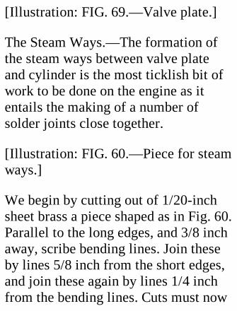
[Illustration: FIG. 69.—Valve plate.]
The Steam Ways.—The formation ofthe steam ways between valve plateand cylinder is the most ticklish bit ofwork to be done on the engine as itentails the making of a number ofsolder joints close together.
[Illustration: FIG. 60.—Piece for steamways.]
We begin by cutting out of 1/20-inchsheet brass a piece shaped as in Fig. 60.Parallel to the long edges, and 3/8 inchaway, scribe bending lines. Join theseby lines 5/8 inch from the short edges,and join these again by lines 1/4 inchfrom the bending lines. Cuts must now

be made along the lines shown doublein Fig. 60. Bend parts CC down andparts BB upwards, so that they are atright angles to parts AA. The positionsof these parts, when the piece isapplied to the cylinder, are shown inFig. 62.
[Illustration: FIG. 61.—Valve plate andsteam ways in section.]
One must now make the bridge pieces(Fig. 61, a, a) to separate the inletpassages from the exhaust. Their widthis the distance between the bent-downpieces CC of Fig. 60, and their bottomedges are shaped to the curvature of thecylinder barrel. Finally, make the
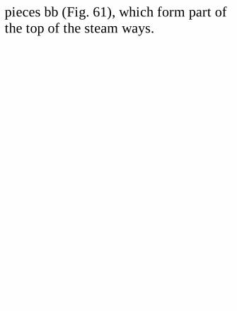
pieces bb (Fig. 61), which form part ofthe top of the steam ways.

In the assembling of these parts ablowpipe spirit lamp or a little "Tinol"soldering lamp will prove very helpful.
The following order should beobserved:
(1.) Solder the piece shown in Fig. 60to the cylinder barrel by the long edges,and to the cylinder supports at the ends.This piece must, of course, cover thesteam ports in the cylinder.
(2.) Put pieces aa (Fig. 61) in position,with their tops quite flush with the topsof BB (Fig. 62), and solder them to thecylinder barrel and sides of the steam-way piece.
(3.) Solder the valve plate centrally toBB, and to the tops of aa, which mustlie between the central and outsideports. Take great care to make steam-tight joints here, and to have the plateparallel to the standards in onedirection and to the cylinder in theother.
(4.) Solder in pieces bb. These shouldbe a tight fit, as it is difficult to holdthem in place while soldering is done.
(5.) Bore a 5/16-inch hole in the lowerside of the central division and solderon the exhaust pipe.
Slide Valve.—The contact part of thisis cut out of flat sheet brass (Fig. 63),
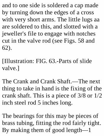
and to one side is soldered a cap madeby turning down the edges of a crosswith very short arms. The little lugs aaare soldered to this, and slotted with ajeweller's file to engage with notchescut in the valve rod (see Figs. 58 and62).
[Illustration: FIG. 63.-Parts of slidevalve.]
The Crank and Crank Shaft.—The nextthing to take in hand is the fixing of thecrank shaft. This is a piece of 3/8 or 1/2inch steel rod 5 inches long.
The bearings for this may be pieces ofbrass tubing, fitting the rod fairly tight.By making them of good length—1

inch—the wear is reduced to almostnothing if the lubricating can is used asoften as it should be.
Each bearing is shown with twostandards. The doubling increasesrigidity, and enables an oil cup to befixed centrally.
The shape of the standards will begathered from Fig. 53, their outlinebeing dotted in behind the crank.
Cut out and bend the standards—afterdrilling the holes for the foot screws—before measuring off for the centres ofthe holes; in fact, follow the course laiddown with regard to the cylinderstandards.
Make a bold scratch across thebedplate to show where the centre lineof the shaft should be, and anotheralong the bed for the piston-rod centreline. (Position given on p. 138.)
Bore holes in the bearings for the oilcups, which may be merely forced inafter the engine is complete.
The crank boss may be made out of abrass disc 2-3/4 inches diameter and3/16 inch thick, from which two curvedpieces are cut to reduce the crank to theshape shown in Fig. 53. The heavierportion, on the side of the shaft awayfrom the crank pin, helps tocounterbalance the weight of the
connecting and piston rods. In Fig. 54(plan of engine) you will see that extraweight in this part has been obtained byfixing a piece of suitably curved metalto the back of the boss.
The mounting of the crank boss on theshaft and the insertion of the crank pininto the boss might well be entrusted toan expert mechanic, as absolute"squareness" is essential forsatisfactory working. Screw-threadattachments should be used, and thecrankshaft should project sufficientlyto allow room for a flat lock nut. Thecrank pin will be rendered immovableby a small lock screw penetrating theboss edgeways and engaging with a
nick in the pin.
Fixing the Standards and Bearings.—Place the two bearings in theirstandards and slip the crank shaftthrough them. Place standards on thebed, with their centre lines on thecrank-shaft centre line. The face of thecrank should be about 3/8 inch awayfrom the piston rod centre line. Bringthe nearer bearing up against the backof the disc, and arrange the standardsequidistantly from the ends of thebearing. The other bearing shouldoverlap the edge of the bed by about1/8 inch. Get all standards square to theedge of the bed, and mark off thepositions of screw holes in bed.
Remove the standards, drill and tap thebed-plate holes, and replace parts asbefore, taking care that the lubricatingholes in the bearings point verticallyupwards. Then solder bearings tostandards.
If any difficulty is experienced ingetting all four standards to bedproperly, make the bearing holes in thetwo inner ones a rather easy fit. Thepresence of the crank-shaft will assurethe bearings being in line when thesoldering is completed.
The standards and bed should havematching marks made on them.
The Eccentric.—This can be formed by
soldering two thin brass discs 1-15/16-inch diameter concentrically to thesides of a disc of 1-15/16-inchdiameter and 5/16 inch thick. Thecentre of the shaft hole must be exactly9/32 inch from the centre of theeccentric to give the proper valve-travel. Drill and tap the eccentricedgeways for a lock screw.
A piece to which the eccentric strap,eccentric rod, and pump rod areattached is cut out of 5/16-inch brass.Its shape is indicated in Fig. 53. Theside next the eccentric must be shapedas accurately as possible to the radiusof the eccentric. The strap, of stripbrass, is fastened to the piece by four

screws, the eccentric rod by twoscrews.
Crosshead and Guides.—The crosshead(Figs. 53 and 54) is built up bysoldering together a flat foot of steel, abrass upright, and a tubular top fittingthe piston rod. The guides, whichconsist of a bed, covers, and distance-pieces united by screws (Fig. 64), haveto withstand a lot of wear, and shouldpreferably be of steel. The importanceof having them quite flat and straightis, of course, obvious.
[Illustration: FIG. 64.—Cross sectionof crosshead and guide.]
The last 1-3/8 inches of the piston rod
has a screw thread cut on it to engagewith a threaded hole in the fork (cut outof thick brass plate), to which the rearend of the connecting rod is pinned,and to take the lock nut which pressesthe crosshead against this fork.
Assuming that all the parts mentionedhave been prepared, the cylinder shouldbe arranged in its proper place on thebed, the piston rod centrally over itscentre line. Mark and drill the screwholes in the bed.
The Valve Gear.—We may now attendto the valve gear. A fork must be madefor the end of the valve rod, andsoldered to it with its slot at right
angles to the slots which engage withthe valve lugs. Slip the rod into thesteam chest, put the valve on the rod,and attach the chest (without the cover)to the valve plate by a bolt at eachcorner. Pull the valve forward till therear port is just uncovered, and turn theeccentric full forward. You will now beable to measure off exactly the distancebetween the centres of the valve-rodfork pin and the rear screw of theeccentric. The valve connecting rod(Fig. 53, VCR) should now be madeand placed in position. If the twoforward holes are filed somewhat slot-shaped, any necessary adjustment ofthe valve is made easier. If theadjustment of VCR and the throw of

the eccentric are correct, the valve willjust expose both end ports alternatelywhen the crank is revolved. If one portis more exposed than the other, adjustby means of the eccentric screws till abalance is obtained. Should the portsstill not be fully uncovered, the throwof the eccentric is too small, and youmust either make a new eccentric orreduce the width of the valve. (Thesecond course has the disadvantage ofreducing the expansive working of thesteam.) Excess movement, on the otherhand, implies too great an eccentricthrow.
Setting the Eccentric.—Turn the crankfull forward, so that a line through the
crank pin and shaft centres is parallelto the bed. Holding it in this position,revolve the eccentric (the screw ofwhich should be slackened offsufficiently to allow the eccentric tomove stiffly) round the shaft in aclockwise direction, until it is in thatposition below the shaft at which thefront steam port just begins to show.Then tighten up the eccentric lockscrew.[1]
[Footnote 1: The reader is referred toan excellent little treatise, entitled "TheSlide Valve" (Messrs. PercivalMarshall and Co., 26 Poppin's Court,Fleet Street, E.C. Price 6d.), for a fullexplanation of the scientific principles
of the slide valve.]
The Connecting Rod.—The length ofthis from centre to centre of the pins onwhich it works should be established asfollows:—Slip over the piston rod adisc of card 1/32 inch thick. Then passthe rod through the gland and assemblethe crosshead and fork on its end, andassemble the guides round thecrosshead foot. Turn the crank pin fullforward, pull the piston rod out as faras it will come, measure the distancebetween pin centres very carefully, andtransfer it to a piece of paper.
The rod consists of a straight centralbar and two rectangular halved ends.
The ends should be cut out of brass andcarefully squared. Through their exactcentres drill 1/8-inch holes, and cut thepieces squarely in two across theseholes. The sawed faces should be fileddown to a good fit and solderedtogether. Now drill holes of the size ofthe pins, using what remains of theholes first made to guide the drill. Thebolt holes are drilled next, and finallythe holes for lubrication and those totake the rods. Then lay the two endsdown on the piece of paper, so thattheir pinholes are centred on the centremarks, and the holes for the rod areturned towards one another. Cut off apiece of steel rod of the proper lengthand unsolder the ends. The rod pieces
must then be assembled on the rod, andwith it be centred on the paper and heldin position while the parts are solderedtogether.
OTHER DETAILS.
Adjusting the Guides.—Put theconnecting rod in place on its pins, andrevolve the crank until the guides havetaken up that position which allows thecrosshead to move freely. Then markoff the holes for the guide holding-down screws, and drill and tap them.
Packings.—The glands and pistonshould be packed with asbestos string.
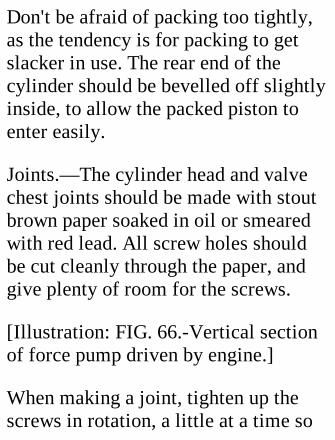
Don't be afraid of packing too tightly,as the tendency is for packing to getslacker in use. The rear end of thecylinder should be bevelled off slightlyinside, to allow the packed piston toenter easily.
Joints.—The cylinder head and valvechest joints should be made with stoutbrown paper soaked in oil or smearedwith red lead. All screw holes shouldbe cut cleanly through the paper, andgive plenty of room for the screws.
[Illustration: FIG. 66.-Vertical sectionof force pump driven by engine.]
When making a joint, tighten up thescrews in rotation, a little at a time so
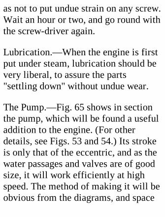
as not to put undue strain on any screw.Wait an hour or two, and go round withthe screw-driver again.
Lubrication.—When the engine is firstput under steam, lubrication should bevery liberal, to assure the parts"settling down" without undue wear.
The Pump.—Fig. 65 shows in sectionthe pump, which will be found a usefuladdition to the engine. (For otherdetails, see Figs. 53 and 54.) Its strokeis only that of the eccentric, and as thewater passages and valves are of goodsize, it will work efficiently at highspeed. The method of making it will beobvious from the diagrams, and space
will therefore not be devoted to adetailed description. The valve ballsshould, of course, be of gun-metal orbrass, and the seatings must beprepared for them by hammering in asteel ball of the same size.
In practice it is advisable to keep thepump always working, and to regulatethe delivery to the boiler by means of aby-pass tap on the feed pipe, throughwhich all or some of the water may bereturned direct to the tank.
The tank, which should be of zinc, mayconveniently be placed under theengine. If the exhaust steam pipe bemade to traverse the tank along or near
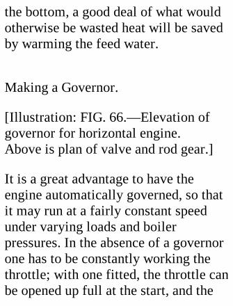
the bottom, a good deal of what wouldotherwise be wasted heat will be savedby warming the feed water.
Making a Governor.
[Illustration: FIG. 66.—Elevation ofgovernor for horizontal engine.Above is plan of valve and rod gear.]
It is a great advantage to have theengine automatically governed, so thatit may run at a fairly constant speedunder varying loads and boilerpressures. In the absence of a governorone has to be constantly working thethrottle; with one fitted, the throttle canbe opened up full at the start, and the
automatic control relied upon toprevent the engine knocking itself topieces.
The vertical centrifugal apparatusshown in Fig. 66 was made by thewriter, and acted very well. The onlyobjection to it is its displacement of thepump from the bed. But a littleingenuity will enable the pump to bedriven off the fly wheel end of thecrank shaft, or, if the shaft is cut offpretty flush with the pulley, off a pin inthe face of the pulley.
Turning to Fig. 66, A is a steel spindlefixed in a base, L, screwed to the bed.B is a brass tube fitting A closely, and
resting at the bottom on a 1/4-inchpiece of similar tubing pinned to A.
A wooden pulley jammed on Btransmits the drive from a belt whichpasses at its other end round a similar,but slightly larger, pulley on the crankshaft. This pulley is accommodated bymoving the eccentric slightly nearerthe crank and shortening the fly-wheelside bearing a little.
The piece G, fixed to B by a lockscrew, has two slots cut in it to take theupper ends of the weight links DD; andC, which slides up and down B, issimilarly slotted for the links EE. Eachof the last is made of two similarly
shaped plates of thin brass, solderedtogether for half their length, butseparated 3/32 inch at the top toembrace the projections of D. Toprevent C revolving relatively to B, anotch is filed in one side of the centralhole, to engage with a piece of brasswire soldered on B (shown solid blackin the diagram). A spiral steel spring,indicated in section by a number ofblack dots, presses at the top againstthe adjustable collar F, and at thebottom against C.
The two weights WW are pieces ofbrass bar slotted for driving on to DD,which taper gently towards the outeredge.
When the pulley revolves, centrifugalforce makes WW fly outwards againstthe pressure of the spring, and the linksEE raise C, which in turn lifts the endof lever M. A single link, N, transmitsthe motion from a pin on M to thedouble bell-crank lever O (see Fig. 66)pivoted on a standard, P, attached tothe bedplate. The slotted upper ends ofP engage with pins on an adjustableblock, R, which moves the governingvalve V (solid black), working in thetube S through a gland. The higher M israised the farther back is V moved, andits annular port is gradually pushedmore out of line with two ports in theside of the valve tube, thus reducingthe flow of steam from the supply pipe
to the cylinder connection on the otherside of the tube. This connection, by-the-bye, acts as fulcrum for lever M,which is made in two parts, heldtogether by screws, to renderdetachment easy.
The closer the fit that V makes with Sthe more effective will the governingbe. The gland at the end of S was takenfrom an old cylinder cover.
Regulation of the speed may beeffected either
(1) by driving the governor faster orslower relatively to the speed of thecrank shaft;
(2) by altering the position of W on D;
(3) by altering the compression of thespring by shifting F;
(4) by a combination of two or more ofthe above.
Generally speaking, (3) is to bepreferred, as the simplest.
The belt may be made out of a bootlaceor fairly stout circular elastic. In eithercase the ends should be chamfered offto form a smooth joint, which may bewrapped externally with thread.
FINAL HINTS.

All parts which have to be fittedtogether should have matching marksmade on them with the punch. To takethe parts of the valve chest as anexample. As we have seen, theseshould be soldered together, finishedoff outside, and drilled. Beforeseparating them make, say, two punchmarks on what will be the upper edgeof the valve plate near the end, and twosimilar marks on the chest as near thefirst as they can conveniently be. Inlike manner mark the chest cover andan adjacent part of the chest with threemarks. It is utterly impossible toreassemble the parts incorrectly afterseparation if the marks are matched.Marking is of greatest importance
where one piece is held up to anotherby a number of screws. If it is omittedin such a case, you may have a lot oftrouble in matching the holesafterwards.
Jacket the cylinder with wood orasbestos, covered in neatly with sheetbrass, to minimize condensation. If thesteam ways, valve chest, and steampipe also are jacketed, an increase inefficiency will be gained, thoughperhaps somewhat at the expense ofappearance.
Boiler.—The boiler described on pp.211-216, or a vertical multitubularboiler with about 800 sq. inches of

heating surface will drive this enginesatisfactorily.
XVI. MODEL STEAMTURBINES.
Steam turbines have come very muchto the fore during recent years,especially for marine propulsion. Inprinciple they are far simpler thancylinder engines, steam being merelydirected at a suitable angle on tospecially shaped vanes attached to arevolving drum and shaft. In theParsons type of turbine the steam

expands as it passes through successiverings of blades, the diameter of whichrings, as well as the length and numberof the blades, increases towards theexhaust end of the casing, so that theincreasing velocity of the expandingsteam may be taken full advantage of.The De Laval turbine includes but asingle ring of vanes, against which thesteam issues through nozzles so shapedas to allow the steam to expandsomewhat and its molecules to bemoving at enormous velocity beforereaching the vanes. A De Laval wheelrevolves at terrific speeds, the limitbeing tens of thousands of turns perminute for the smallest engines. Thegreatest efficiency is obtained,
theoretically, when the vane velocity ishalf that of the steam, the latter, afterpassing round the curved insidesurfaces of the vanes, being robbed ofall its energy and speed. (For a fullerdescription of the steam turbine, seeHow It Works, Chap. III., pp.74-86.)
The turbines to be described work onthe De Laval principle, which has beenselected as the easier for the beginnerto follow.
A Very Simple Turbine.
We will begin with a very simplecontrivance, shown in Fig. 67. As a"power plant" it is confessedly useless,but the making of it affords amusement
and instruction. For the boiler select acircular tin with a jointless stampedlid, not less than 4 inches in diameter,so as to give plenty of heating surface,and at least 2-1/2 inches deep, toensure a good steam space andmoderately dry steam. A shallow boilermay "prime" badly, if reasonably full,and fling out a lot of water with thesteam.
Clean the metal round the joints, andpunch a small hole in the lid, half aninch from the edge, to give egress tothe heated air during the operation ofsoldering up the point or joints, whichmust be rendered absolutely water-tight.
[Illustration: FIG. 67.—Simple steamturbine.]
For the turbine wheel take a piece ofthin sheet iron or brass; flatten it out,and make a slight dent in it an inchfrom the two nearest edges. With thisdent as centre are scribed two circles,of 3/4 and 1/2 inch radius respectively.Then scratch a series of radial marksbetween the circles, a fifth of an inchapart. Cut out along the outer circle,and with your shears follow the radiallines to the inner circle. The edge isthus separated into vanes (Fig. 68), theends of which must then be twistedround through half a right angle, withthe aid of a pair of narrow-nosed pliers,
care being taken to turn them all in thesame direction.
[Illustration: FIG. 68.—Wheel forsteam turbine, showing one vanetwisted into final position.]
A spindle is made out of a large pin,beheaded, the rough end of which mustbe ground or filed to a sharp point.Next, just break through the metal ofthe disc at the centre with a sharpenedwire nail, and push the spindle throughtill it projects a quarter of an inch orso. Soldering the disc to the spindle ismost easily effected with a blowpipe orsmall blow-lamp.
The Boiler.—In the centre of the boiler
make a dent, to act as bottom bearingfor the spindle. From this centredescribe a circle of 5/8-inch radius. Onthis circle must be made the steam portor ports. Two ports, at opposite ends ofa diameter, give better results than asingle port, as equalizing the pressureon the vanes, so that the spindle isrelieved of bending strains. Theircombined area must not, however,exceed that of the single port, if oneonly be used. It is important to keep inmind that for a turbine of this kindvelocity of steam is everything, andthat nothing is gained by increasing thenumber or size of ports if it causes afall in the boiler pressure.
The holes are best made with a tinyMorse twist drill. As the metal is thin,drill squarely, so that the steam shallemerge vertically.
For the upper bearing bend a piece oftin into the shape shown in Fig. 67. Thevertical parts should be as nearly aspossible of the same length as thespindle. In the centre of the undersideof the standard make a deep dent,supporting the metal on hard wood orlead, so that it shall not be pierced. Ifthis accident occurs the piece isuseless.
Place the wheel in position, the longerpart of the spindle upwards, and move
the standard about until the spindle isvertical in all directions. Scratch roundthe feet of the standard to mark theirexact position, and solder the standardto the boiler. The top of the standardmust now be bent slightly upwards ordownwards until the spindle is heldsecurely without being pinched.
A 3/16-inch brass nut and screw, thefirst soldered to the boiler round a holeof the same size as its internaldiameter, make a convenient "filler;"but a plain hole plugged with a taperedpiece of wood, such as the end of apenholder, will serve.
Half fill the boiler by immersion in hot
water, the large hole being keptlowermost, and one of the steam ventsabove water to allow the air to escape.
A spirit lamp supplies the necessaryheat. Or the boiler may be held in awire cradle over the fire, near enoughto make the wheel hum. Be careful notto over-drive the boiler. As a woodenplug will probably be driven out beforethe pressure can become dangerous,this is a point in favour of using one.Corrosion of the boiler will be lessenedif the boiler is kept quite full of waterwhen not in use.
A Practical Steam Turbine.
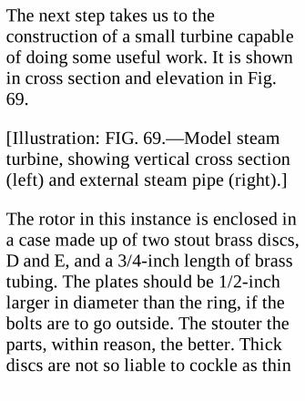
The next step takes us to theconstruction of a small turbine capableof doing some useful work. It is shownin cross section and elevation in Fig.69.
[Illustration: FIG. 69.—Model steamturbine, showing vertical cross section(left) and external steam pipe (right).]
The rotor in this instance is enclosed ina case made up of two stout brass discs,D and E, and a 3/4-inch length of brasstubing. The plates should be 1/2-inchlarger in diameter than the ring, if thebolts are to go outside. The stouter theparts, within reason, the better. Thickdiscs are not so liable to cockle as thin

ones, and a stout ring will make itpossible to get steam-tight joints withbrown-paper packing.
The wheel is a disc of brass, say, 1/25inch thick and 4 inches in diameter; thespindle is 3/16 inch, of silver steel rod;the bearings, brass tubing, making aclose fit on the rod.
If you cannot get the ring ends turnedup true in a lathe—a matter of but afew minutes' work—rub them down ona piece of emery cloth supported on atrue surface, such as a piece of thickglass.
Now mark out accurately the centres ofthe discs on both sides, and make
marks to show which face of each discis to be outside.
On the outside of both scribe circles ofthe size of the bearing tubes, and othercircles at the proper radius for the bolthole centres.
On the outside of D scribe two circlesof 2-inch and 1-11/16-inch radius,between which the steam pipe will lie.
On the inside of D scribe a circle of 1-27/32-inch radius for the steam ports.
On the outside of E mark a 7/8-inchcircle for the exhaust pipe.
On the inside of both mark the circles
between which the ring must lie.
Bolt Holes.—The marks for these, sixor twelve in number, are equallyspaced on the outside of one plate, andthe two plates are clamped or solderedtogether before the boring is done, toensure the holes being in line. If thebolts are to screw into one plate, becareful to make the holes of the tappingsize in the first instance, and to enlargethose in D afterwards. Make guidemarks in the plates before separating,between what will be the uppermostholes and the circumference.
Bolts.—These should be of brass ifpassed inside the ring. Nuts are not

necessary if E is tapped, but theiraddition will give a smarter appearanceand prevent-the bolts becoming loose.
Bearings.—Bore central holes in thediscs to a good fit for the bearings, andprepare the hole for the exhaust pipe.This hole is most easily made bydrilling a ring of small holes just insidethe mark and cutting through theintervening metal.
For A, B, and C cut off pieces ofbearing pipe, 1/2, 1/4, and 3/4 inchlong respectively, and bevel the ends ofB and C as shown, to minimize frictionif they rub. File all other ends square.(Lathe useful here.)
Bore oil holes in B and C, and clearaway all the "burr." Make scratches onthe bearings to show how far theyshould be pushed through the case.
Now assemble the case, taking carethat the edge of the ring correspondsexactly with the circles marked on thediscs, and clean the metal round thebearing holes and the bearingsthemselves. The last are then placed inposition, with the lubricating holespointing upwards towards the guidemarks on the discs. Push the spindlerod through the bearings, which mustbe adjusted until the rod can berevolved easily with the fingers. Thensolder in the bearing with a "Tinol"
lamp.
The Wheel.—Anneal this well byheating to a dull red and plunging it incold water. Mark a circle of 1-1/4-inchradius, and draw radial lines 1/4 inchapart at the circumference from thiscircle to the edge. Cut out along thelines, and twist the vanes to make anangle of about 60 degree with thecentral part, and bend the ends slightlybackward away from the direction inwhich the rotor will revolve. (Thedirections given on p. 189 for making asteam top wheel can be applied here.)
Bore a hole in the centre to make atight fit with the spindle, and place the
rotor in position, with piece B incontact on the C side. Get everythingsquare (rotation will betray a badwobble), and solder the three partstogether with the blow-lamp.
Mount the rotor squarely by the spindlepoints between two pieces of woodheld lightly in the vice, and, with theaid of a gauge fixed to the piece nearestthe wheel, true up the line of the vanes.(Lathe useful here.)
The Steam Pipe is 15 inches (or more)of 5/16-inch copper tubing, wellannealed. To assist the bending of itinto a ring one needs some circularobject of the same diameter as the
interior diameter of the ring roundwhich to curve it. I procured a tooth-powder box of the right size, and nailedit firmly to a piece of board. Then Ibevelled off the end of the pipe to theapproximately correct angle, laid itagainst the box, and drove in a nail tokeep it tight up. Bending was then aneasy matter, a nail driven in here andthere holding the pipe until the ringwas complete. I then soldered the endto the standing part, and detached thering for flattening on one side with afile and emery cloth. This done, I boreda hole through the tube at F to open upthe blind end of the ring.
Attaching the ring to disc D is effected
as follows:—Tin the contact faces ofthe ring and disc pretty heavily withsolder, after making poppet marksround the guide circles so that theymay not be lost under the solder. Thering must be pressed tightly against itsseat while heating is done with thelamp. An extra pair of hands makesthings easier at this point. Be carefulnot to unsolder the spindle bearing, athing which cannot happen if thebearing is kept cool by an occasionaldrop or two of water. A little extrasolder should be applied round thepoints where the ports will be.
The Steam Ports.—These are drilled(with a 1/32-inch twist drill), at an

angle of about 30 degrees to the plate,along the circle already scribed. If youhave any doubt as to your boiler'scapacity, begin with one hole only, andadd a second if you think it advisable.As already remarked, pressure must notbe sacrificed to steam flow.
Lubricators.—These are short pieces oftubing hollowed at one end by a roundfile of the same diameter as thebearings. A little "Tinol" is smearedover the surfaces to be joined, and thelubricators are placed in position andheated with the blow-lamp until thesolder runs. To prevent the oil flowingtoo freely, the lubricators should beprovided with airtight wooden plugs.
Escape Pipes.—The pipe for theexhaust steam is now soldered into discE, and a small water escape into thering at its lowest point. This pipeshould be connected with a closedchamber or with the exhaust at a pointlower than the base of the turbine case.
Stirrup.—Fig. 69 shows a stirrupcarrying a screw which presses againstthe pulley end of the spindle. Thisattachment makes it easy to adjust thedistance between the rotor and thesteam ports, and also concentrates allend thrust on to a point, therebyminimizing friction. The stirrup can befashioned in a few minutes out of brassstrip. Drill the holes for the holding-on
screws; drill and tap a hole for theadjusting screw; insert the screw andcentre it correctly on the spindle point.Then mark the position of the twoscrew holes in E; drill and tap them.
Feet are made of sheet brass, drilled totake the three (or two) lowermost bolts,and bent to shape. Note.—A side andfoot may be cut out of one piece ofmetal. The difficulty is that thebending may distort the side, andprevent a tight joint between side andring.
Assembling.—Cut out two rings ofstout brown paper a quarter of an inchwide and slightly larger in diameter

than the casing ring. In assembling theturbine finally, these, after beingsoaked in oil, should be insertedbetween the ring and the discs. Put infour screws only at first, and get thering properly centred and the bearingsexactly in line, which will be shown bythe spindle revolving easily. Thentighten up the nuts and insert the otherbolts, the three lowest of which arepassed through the feet. Affix thepulley and stirrup, and adjust thespindle longitudinally until the rotorjust does not rub the casing. Thesoldering on of the cap of A completesoperations.
To get efficiency, heavy gearing down
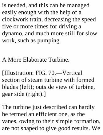
is needed, and this can be managedeasily enough with the help of aclockwork train, decreasing the speedfive or more times for driving adynamo, and much more still for slowwork, such as pumping.
A More Elaborate Turbine.
[Illustration: FIG. 70.—Verticalsection of steam turbine with formedblades (left); outside view of turbine,gear side (right).]
The turbine just described can hardlybe termed an efficient one, as thevanes, owing to their simple formation,are not shaped to give good results. We
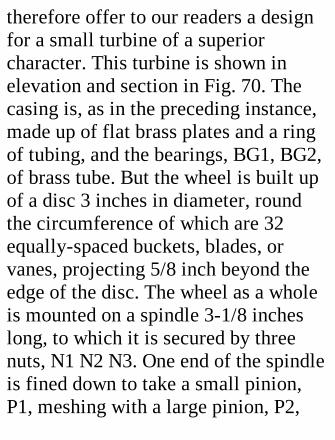
therefore offer to our readers a designfor a small turbine of a superiorcharacter. This turbine is shown inelevation and section in Fig. 70. Thecasing is, as in the preceding instance,made up of flat brass plates and a ringof tubing, and the bearings, BG1, BG2,of brass tube. But the wheel is built upof a disc 3 inches in diameter, roundthe circumference of which are 32equally-spaced buckets, blades, orvanes, projecting 5/8 inch beyond theedge of the disc. The wheel as a wholeis mounted on a spindle 3-1/8 incheslong, to which it is secured by threenuts, N1 N2 N3. One end of the spindleis fined down to take a small pinion,P1, meshing with a large pinion, P2,
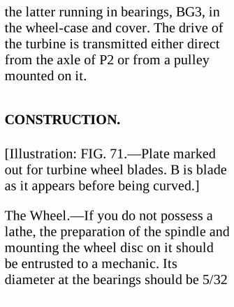
the latter running in bearings, BG3, inthe wheel-case and cover. The drive ofthe turbine is transmitted either directfrom the axle of P2 or from a pulleymounted on it.
CONSTRUCTION.
[Illustration: FIG. 71.—Plate markedout for turbine wheel blades. B is bladeas it appears before being curved.]
The Wheel.—If you do not possess alathe, the preparation of the spindle andmounting the wheel disc on it shouldbe entrusted to a mechanic. Itsdiameter at the bearings should be 5/32
inch or thereabouts. (Get the tubing forthe bearings and for the spindle turnedto fit.) The larger portion is about twiceas thick as the smaller, to allow roomfor the screw threads. The right-handend is turned down quite small for thepinion, which should be of driving fit.
The Blades.—Mark out a piece of sheetiron as shown in Fig. 71 to form 32rectangles, 1 by l/2 inch. The metal isdivided along the lines aaaa, bbbb, andab, ab, ab, ab, etc. The piece for eachblade then has a central slot 5/16 inchlong and as wide as the wheel disc cutvery carefully in it.
Bending the Blades.—In the edge of a
piece of hard wood 1 inch thick file anotch 3/8 inch wide and 1/8 inch deepwith a 1/2-inch circular file, andprocure a metal bar which fits thegroove loosely. Each blade is laid inturn over the groove, and the bar isapplied lengthwise on it and drivendown with a mallet, to give the bladethe curvature of the groove. When allthe blades have been made and shaped,draw 16 diameters through the centreof the wheel disc, and at the 32 endsmake nicks 1/16 inch deep in thecircumference.
True up the long edges of the bladeswith a file, and bring them off to asharp edge, removing the metal from
the convex side.
Fixing the Blades.—Select a piece ofwood as thick as half the width of afinished blade, less half the thicknessof the wheel disc. Cut out a circle ofthis wood 2 inches in diameter, andbore a hole at the centre. The wheeldisc is then screwed to a perfectly flatboard or plate, the wooden disc beingused as a spacer between them.
Slip a blade into place on the disc,easing the central slit, if necessary, toallow the near edge to lie in contactwith the board—that is parallel to thedisc. Solder on the blade, using theminimum of solder needed to make a
good joint. When all the blades arefixed, you will have a wheel with theblades quite true on one side. It is,therefore, important to consider, beforecommencing work, in which directionthe concave side of the blades shouldbe, so that when the wheel is mountedit shall face the nozzle.
To make this point clear: the directionof the nozzle having been decided, thebuckets on the trued side must in turnpresent their concave sides to thenozzle. In Fig. 70 the nozzle pointsdownwards, and the left side of thewheel has to be trued. Therefore B1 hasits convex, B2 its concave, side facingthe reader, as it were.
The Nozzle is a 1-1/2 inch piece ofbrass bar. Drill a 1/20-inch holethrough the centre. On the outside end,enlarge this hole to 1/8 inch to a depthof 1/8 inch. The nozzle end is bevelledoff to an angle of 20 degrees, and abroach is inserted to give the steamport a conical section, as shown in Fig.72, so that the steam may expand andgain velocity as it approaches theblades. Care must be taken not to allowthe broach to enter far enough toenlarge the throat of the nozzle to morethan 1/20 inch.
[Illustration: FIG. 72.—Nozzle ofturbine, showing its position relativelyto buckets.]

Fixing the Nozzle.—The centre of thenozzle discharge opening is 1-13/16-inches from the centre of the wheel.The nozzle must make an angle of 20degrees with the side of the casing,through which it projects far enough toall but touch the nearer edges of thevanes. (Fig. 72.) The wheel can then beadjusted, by means of the spindle nuts,to the nozzle more conveniently thanthe nozzle to the wheel. To get the holein the casing correctly situated andsloped, begin by boring a hole straightthrough, 1/4 inch away laterally fromwhere the steam discharge hole will be,centre to centre, and then work thewalls of the hole to the proper anglewith a circular file of the same
diameter as the nozzle piece, which isthen sweated in with solder. It is, ofcourse, an easy matter to fix the nozzleat the proper angle to a thin plate,which can be screwed on to the outsideof the casing, and this method has theadvantage of giving easy detachmentfor alteration or replacement.
Balancing the Wheel.—As the wheelwill revolve at very high speed, itshould be balanced as accurately aspossible. A simple method of testing isto rest the ends of the spindle on twocarefully levelled straight edges. If thewheel persists in rolling till it takes upa certain position, lighten the lowerpart of the wheel by scraping off
solder, or by cutting away bits of thevanes below the circumference of thedisc, or by drilling holes in the discitself.
Securing the Wheel.—When the wheelhas been finally adjusted relatively tothe nozzle, tighten up all the spindlenuts hard, and drill a hole for a pinthrough them and the disc parallel tothe spindle, and another through N3and the spindle. (Fig. 70.)
Gearing.—The gear wheels should beof good width, not less than 3/16 inch,and the smaller of steel, to withstandprolonged wear. Constant lubrication isneeded, and to this end the cover
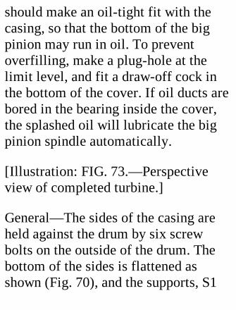
should make an oil-tight fit with thecasing, so that the bottom of the bigpinion may run in oil. To preventoverfilling, make a plug-hole at thelimit level, and fit a draw-off cock inthe bottom of the cover. If oil ducts arebored in the bearing inside the cover,the splashed oil will lubricate the bigpinion spindle automatically.
[Illustration: FIG. 73.—Perspectiveview of completed turbine.]
General—The sides of the casing areheld against the drum by six screwbolts on the outside of the drum. Thebottom of the sides is flattened asshown (Fig. 70), and the supports, S1
S2, made of such a length that whenthey are screwed down the flattenedpart is pressed hard against the bed.The oil box on top of the casing has apad of cotton wool at the bottom toregulate the flow of oil to the bearings.Fit a drain pipe to the bottom of thewheel-case.
Testing.—If your boiler will makesteam above its working pressure fasterthan the turbine can use it, the nozzlemay be enlarged with a broach until itpasses all the steam that can be raised;or a second nozzle may be fitted on theother end of the diameter on which thefirst lies. This second nozzle shouldhave a separate valve, so that it can be
shut off.
XVIL. STEAM TOPS.
A very interesting and novelapplication of the steam turbineprinciple is to substitute for a wheelrunning in fixed bearings a "free"wheel pivoted on a vertical spindle, thepoint of which takes the weight, so thatthe turbine becomes a top which can bekept spinning as long as the steamsupply lasts.
These toys, for such they must beconsidered, are very easy to make, and
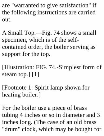
are "warranted to give satisfaction" ifthe following instructions are carriedout.
A Small Top.—Fig. 74 shows a smallspecimen, which is of the self-contained order, the boiler serving assupport for the top.
[Illustration: FIG. 74.-Simplest form ofsteam top.] [1]
[Footnote 1: Spirit lamp shown forheating boiler.]
For the boiler use a piece of brasstubing 4 inches or so in diameter and 3inches long. (The case of an old brass"drum" clock, which may be bought for
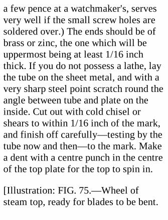
a few pence at a watchmaker's, servesvery well if the small screw holes aresoldered over.) The ends should be ofbrass or zinc, the one which will beuppermost being at least 1/16 inchthick. If you do not possess a lathe, laythe tube on the sheet metal, and with avery sharp steel point scratch round theangle between tube and plate on theinside. Cut out with cold chisel orshears to within 1/16 inch of the mark,and finish off carefully—testing by thetube now and then—to the mark. Makea dent with a centre punch in the centreof the top plate for the top to spin in.
[Illustration: FIG. 75.—Wheel ofsteam top, ready for blades to be bent.

A hole is drilled at the inner end ofevery slit to make bending easier.]
Solder the plates into the tube,allowing an overlap of a quarter of aninch beyond the lower one, to helpretain the heat.
The top wheel is cut out of a flat pieceof sheet iron, zinc, or brass. Itsdiameter should be about 2-1/2 inches,the vanes 1/2 inch long and 1/4 inchwide at the circumference. Turn themover to make an angle of about 45degrees with the spindle. They will bemore easily bent and give better resultsif holes are drilled, as shown in Fig. 75.
The spindle is made out of a bit of steel
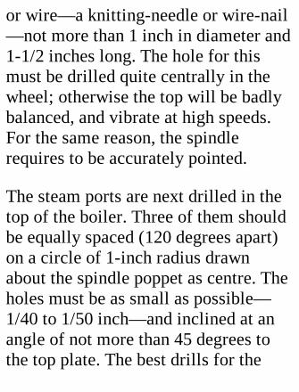
or wire—a knitting-needle or wire-nail—not more than 1 inch in diameter and1-1/2 inches long. The hole for thismust be drilled quite centrally in thewheel; otherwise the top will be badlybalanced, and vibrate at high speeds.For the same reason, the spindlerequires to be accurately pointed.
The steam ports are next drilled in thetop of the boiler. Three of them shouldbe equally spaced (120 degrees apart)on a circle of 1-inch radius drawnabout the spindle poppet as centre. Theholes must be as small as possible—1/40 to 1/50 inch—and inclined at anangle of not more than 45 degrees tothe top plate. The best drills for the
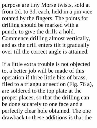
purpose are tiny Morse twists, sold atfrom 2d. to 3d. each, held in a pin vicerotated by the fingers. The points fordrilling should be marked with apunch, to give the drills a hold.Commence drilling almost vertically,and as the drill enters tilt it graduallyover till the correct angle is attained.
If a little extra trouble is not objectedto, a better job will be made of thisoperation if three little bits of brass,filed to a triangular section (Fig. 76 a),are soldered to the top plate at theproper places, so that the drilling canbe done squarely to one face and aperfectly clear hole obtained. The onedrawback to these additions is that the
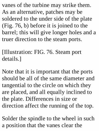
vanes of the turbine may strike them.As an alternative, patches may besoldered to the under side of the plate(Fig. 76, b) before it is joined to thebarrel; this will give longer holes and atruer direction to the steam ports.
[Illustration: FIG. 76. Steam portdetails.]
Note that it is important that the portsshould be all of the same diameter andtangential to the circle on which theyare placed, and all equally inclined tothe plate. Differences in size ordirection affect the running of the top.
Solder the spindle to the wheel in sucha position that the vanes clear the
boiler by an eighth of an inch or so. Iftests show that the top runs quitevertically, the distance might bereduced to half, as the smaller it is themore effect will the steam jets have.
A small brass filler should be affixedto the boiler halfway up. A filler withground joints costs about 6d.
A wick spirit lamp will serve to raisesteam. Solder to the boiler three legs ofsuch a length as to give an inchclearance between the lamp wick andthe boiler. If the wick is arranged toturn up and down, the speed of the topcan be regulated.
A Large Top.—The top just described

must be light, as the steam driving it islow-pressure, having free egress fromthe boiler, and small, as the steam hascomparatively low velocity. Thepossessor of a high-pressure boiler maybe inclined to make something rathermore ambitious—larger, heavier, anduseful for displaying spectrum discs,etc.
The top shown in Fig. 77 is 3 inches indiameter, weighs 1 oz., and was cut outof sheet-zinc. It stands on a brass disc,round the circumference of which issoldered a ring of 5/32-inch coppertubing, furnished with a union forconnection with a boiler.
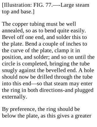
[Illustration: FIG. 77.—-Large steamtop and base.]
The copper tubing must be wellannealed, so as to bend quite easily.Bevel off one end, and solder this tothe plate. Bend a couple of inches tothe curve of the plate, clamp it inposition, and solder; and so on until thecircle is completed, bringing the tubesnugly against the bevelled end. A holeshould now be drilled through the tubeinto this end—so that steam may enterthe ring in both directions-and pluggedexternally.
By preference, the ring should bebelow the plate, as this gives a greater
thickness of metal for drilling, and alsomakes it easy to jacket the tube bysinking the plate into a wooden disc ofsomewhat greater diameter.
Under 50 lbs. of steam, a top of thiskind attains a tremendous velocity.Also, it flings the condensed steamabout so indiscriminately that a ring ofzinc 3 inches high and 18 inches indiameter should be made wherewith tosurround it while it is running.
If a little bowl with edges turned overbe accurately centred on the wheel, ademonstration of the effects ofcentrifugal force may be made withwater, quicksilver, or shot, which fly
up into the rim and disappear as the topattains high speed, and come into sightagain when its velocity decreases to acertain figure. A perforated metalglobe threaded on the spindle gives thefamiliar humming sound.
A spectrum disc of the seven primarycolours—violet, indigo, blue, green,yellow, orange, red—revolved by thetop, will appear more or less white, thepurity of which depends on theaccuracy of the tints used.
XVIII. MODEL BOILERS.

A chapter devoted to the constructionof model boilers may well open with afew cautionary words, as the dangersconnected with steam-raisers are veryreal; and though model-boilerexplosions are fortunately rare, if theydo occur they may be extremelydisastrous.
Therefore the following warnings:—
(1.) Do not use tins or thin sheet ironfor boilers. One cannot tell how farinternal corrosion has gone. Thescaling of 1/100 inch of metal off a"tin" is obviously vastly more seriousthan the same diminution in thethickness of, say, a 1/4-inch plate.
Brass and copper are the metals toemploy, as they do not deteriorate at allprovided a proper water supply bemaintained.
(2.) If in doubt, make the boiler muchmore solid than is needed, rather thanrun any risks.
(3.) Fit a steam gauge, so that you mayknow what is happening.
(4.) Test your boiler under steam, anddon't work it at more than half thepressure to which it has been tested.(See p. 220.)
In the present chapter we will assumethat the barrels of all the boilers

described are made out of solid-drawnseamless copper tubing, which can bebought in all diameters up to 6 inches,and of any one of several thicknesses.Brass tubing is more easily soldered,but not so good to braze, and generallynot so strong as copper, other thingsbeing equal. Solid-drawn tubing ismore expensive than welded tubing oran equivalent amount of sheet metal,but is considerably stronger than thebest riveted tube.
Boiler ends may be purchased readyturned to size. Get stampings ratherthan castings, as the first are morehomogeneous, and therefore can besomewhat lighter.
Flanging Boiler Ends.—To make agood job, a plate for an end should bescrewed to a circular block of hardwood (oak or boxwood), having anoutside diameter less than the insidediameter of the boiler barrel by twicethe thickness of the metal of the end,and a rounded-off edge. The plate mustbe annealed by being heated to a dullred and dipped in cold water. Theprocess must be repeated should thehammering make the copper stubborn.
Stays should be used liberally, and bescrewed and nutted at the ends. As thecutting of the screw thread reduces theeffective diameter, the strength of astay is only that of the section at the
bottom of the threads.
Riveting.—Though stays will preventthe ends of the boiler blowing off, it isvery advisable to rivet them throughthe flanges to the ends of the barrel, asthis gives mutual supportindependently of soldering or brazing.Proper boiler rivets should be procured,and annealed before use. Make therivet holes a good fit, and drill the twoparts to be held together in oneoperation, to ensure the holes being inline. Rivets will not close properly iftoo long. Dies for closing the rivetheads may be bought for a few pence.
Soldering, etc.—Joints not exposed

directly to the furnace flames may besoldered with a solder melting notbelow 350 degrees Fahr. Surfaces to beriveted together should be "tinned"before riveting, to ensure the soldergetting a good hold afterwards. Thesolder should be sweated right throughthe joint with a blow-lamp to make asatisfactory job.
All joints exposed to the flames shouldbe silver-soldered, and other joints aswell if the working pressure is toexceed 50 lbs. to the square inch.Silver-soldering requires the use of apowerful blow—lamp or gas-jet;ordinary soft soldering bits andtemperatures are ineffective. Brazing is
better still, but should be done by anexpert, who may be relied on not toburn the metal. It is somewhat risky tobraze brass, which melts at atemperature not far above that requiredto fuse the spelter (brass solder).Getting the prepared parts of a boilersilver-soldered or brazed together isinexpensive, and is worth the moneyasked.
[Illustration: FIG. 78.]
Some Points in Design.
The efficiency of a boiler is governedchiefly (1) by the amount of heatingsurface exposed to the flames; (2) by

the distribution of the heating surface;(3) by the amount of fuel which can beburnt in the furnace in a given time; (4)by avoiding wastage of heat.
The simplest form of boiler, depictedin Fig. 78, is extremely inefficientbecause of its small heating surface. Agreat deal of the heat escapes round thesides and the ends of the boiler.Moreover, a good deal of the heatwhich passes into the water is radiatedout again, as the boiler is exposeddirectly to the air.
Fig. 79 shows a great improvement indesign. The boiler is entirely enclosed,except at one end, so that the hot gases
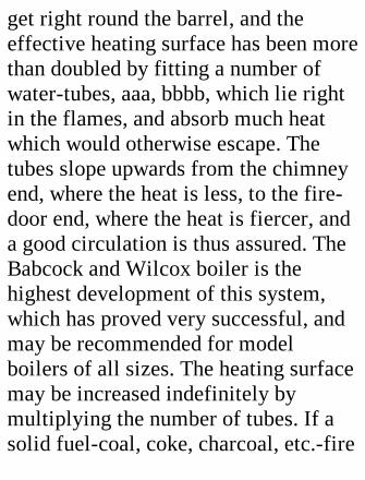
get right round the barrel, and theeffective heating surface has been morethan doubled by fitting a number ofwater-tubes, aaa, bbbb, which lie rightin the flames, and absorb much heatwhich would otherwise escape. Thetubes slope upwards from the chimneyend, where the heat is less, to the fire-door end, where the heat is fiercer, anda good circulation is thus assured. TheBabcock and Wilcox boiler is thehighest development of this system,which has proved very successful, andmay be recommended for modelboilers of all sizes. The heating surfacemay be increased indefinitely bymultiplying the number of tubes. If asolid fuel-coal, coke, charcoal, etc.-fire
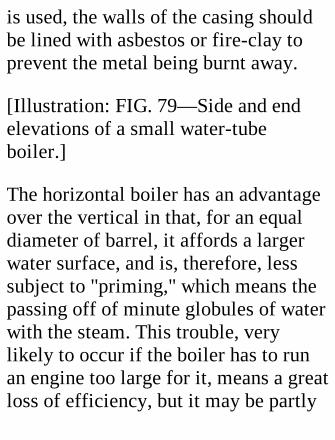
is used, the walls of the casing shouldbe lined with asbestos or fire-clay toprevent the metal being burnt away.
[Illustration: FIG. 79—Side and endelevations of a small water-tubeboiler.]
The horizontal boiler has an advantageover the vertical in that, for an equaldiameter of barrel, it affords a largerwater surface, and is, therefore, lesssubject to "priming," which means thepassing off of minute globules of waterwith the steam. This trouble, verylikely to occur if the boiler has to runan engine too large for it, means a greatloss of efficiency, but it may be partly

cured by making the steam passthrough coils exposed to the furnacegases on its way to the engine. This"superheating" evaporates the globulesand dries the steam, besides raising itstemperature. The small water-tube ispreferable to the small fire-tubeconnecting furnace and chimney, as itssurface is exposed more directly to theflames; also it increases, instead ofdecreasing, the total volume of water inthe boiler.
A Vertical Boiler.
[Illustration: FIG. 80.—Details ofvertical boiler.]
The vertical boiler illustrated by Fig.80 is easily made. The absence of awater jacket to the furnace is partlycompensated by fitting six water-tubesin the bottom. As shown, the barrel is 8inches long and 6 inches in outsidediameter, and the central flue 1-1/2inches across outside solid-drawn 1/16-inch tubing, flanged ends, and four 1/4-inch stays—disposed as indicated inFig. 80 (a) and (b)—are used. The 5/16or 3/8 inch water-tubes must beannealed and filled with lead or resinbefore being bent round woodentemplates. After bending, run the resinor lead out by heating. The outflow endof each pipe should project half an inchor so further through the boiler bottom
than the inflow end.
Mark out and drill the tube holes in thebottom, and then the flue hole, forwhich a series of small holes must bemade close together inside thecircumference and united with a fretsaw. Work the hole out carefully tillthe flue, which should be slightlytapered at the end, can be driventhrough an eighth of an inch or so. Theflue hole in the top should be made agood fit, full size.
Rivet a collar, x (Fig. 80, a), of stripbrass 1/4 inch above the bottom of theflue to form a shoulder. Another collar,y (Fig. 80, c), is needed for the flue
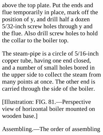
above the top plate. Put the ends andflue temporarily in place, mark off theposition of y, and drill half a dozen5/32-inch screw holes through y andthe flue. Also drill screw holes to holdthe collar to the boiler top.
The steam-pipe is a circle of 5/16-inchcopper tube, having one end closed,and a number of small holes bored inthe upper side to collect the steam frommany points at once. The other end iscarried through the side of the boiler.
[Illustration: FIG. 81.—Perspectiveview of horizontal boiler mounted onwooden base.]
Assembling.—The order of assembling
is:—Rivet in the bottom; put thesteam-pipe in place; rivet in the top;insert the flue, and screw collar y to thetop; expand the bottom of the flue byhammering so that it cannot bewithdrawn; insert the stays and screwthem up tight; silver-solder both endsof the flue, the bottom ends of thestays, and the joint between bottom andbarrel. The water-tubes are theninserted and silver-soldered, and onefinishes by soft-soldering the boiler topto the barrel and fixing in the seatingsfor the water and steam gauges, safety-valve, mud-hole, filler, and pump-if thelast is fitted.
The furnace is lined with a strip of
stout sheet iron, 7 inches wide and 19-1/4 inches long, bent round the barrel,which it overlaps for an inch and a half.Several screws hold lining and barreltogether. To promote efficiency, thefurnace and boiler is jacketed withasbestos—or fire-clay round thefurnace—secured by a thin outer cover.The enclosing is a somewhattroublesome business, but results inmuch better steaming power, especiallyin cold weather. Air-holes must be cutround the bottom of the lining to givegood ventilation.
A boiler of this size will keep a 1 by 1-1/2 inch cylinder well supplied withsteam at from 30 to 40 lbs. per square

inch.
A Horizontal Boiler.
[Illustration: FIG. 82.—Longitudinalsection of large water-tube boiler.]
The boiler illustrated by Fig. 81 isdesigned for heating with a largeparaffin or petrol blow-lamp. It hasconsiderably greater water capacity,heating surface—the furnace beingentirely enclosed—and water surfacethan the boiler just described. The lastat high-water level is about 60, and atlow-water level 70, square inches.
The vertical section (Fig. 82) shows
1/16-inch barrel, 13 inches long overall and 12 inches long between the endplates, and 6 inches in diameter. Thefurnace flue is 2-1/2 inches acrossoutside, and contains eleven 1/2-inchcross tubes, set as indicated by the endview (Fig. 83), and 3/4 inch apart,centre to centre. This arrangementgives a total heating surface of about140 square inches. If somewhat smallertubes are used and doubled (see Fig.84), or even trebled, the heating surfacemay be increased to 180-200 squareinches. With a powerful blow-lamp thisboiler raises a lot of steam.
Tubing the Furnace Flue.—Before anyof the holes are made, the lines on
which the centres lie must be scoredfrom end to end of the flue on theoutside. The positions of these lines arequickly found as follows:—Cut out astrip of paper exactly as long as thecircumference of the tube, and plot thecentre lines on it. The paper is thenapplied to the tube again, and poppetmarks made with a centre punchopposite to or through the marks on thepaper. Drive a wire-nail through apiece of square wood and sharpen thepoint. Lay the flue on a flat surface,apply the end of the nail to one of thepoppet marks, and draw it along theflue, which must be held quite firmly.When all the lines have been scored,the centring of the water tubes is a very
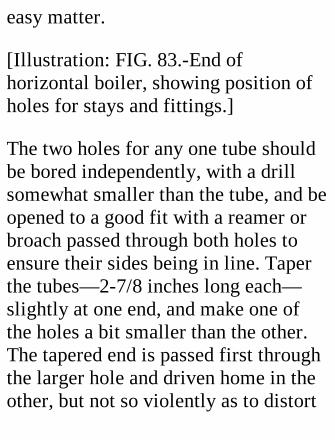
easy matter.
[Illustration: FIG. 83.-End ofhorizontal boiler, showing position ofholes for stays and fittings.]
The two holes for any one tube shouldbe bored independently, with a drillsomewhat smaller than the tube, and beopened to a good fit with a reamer orbroach passed through both holes toensure their sides being in line. Taperthe tubes—2-7/8 inches long each—slightly at one end, and make one ofthe holes a bit smaller than the other.The tapered end is passed first throughthe larger hole and driven home in theother, but not so violently as to distort
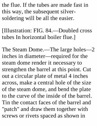
the flue. If the tubes are made fast inthis way, the subsequent silver-soldering will be all the easier.
[Illustration: FIG. 84.—Doubled crosstubes In horizontal boiler flue.]
The Steam Dome.—The large holes—2inches in diameter—required for thesteam dome render it necessary tostrengthen the barrel at this point. Cutout a circular plate of metal 4 inchesacross, make a central hole of the sizeof the steam dome, and bend the plateto the curve of the inside of the barrel.Tin the contact faces of the barrel and"patch" and draw them together withscrews or rivets spaced as shown in
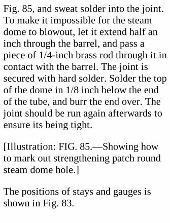
Fig. 85, and sweat solder into the joint.To make it impossible for the steamdome to blowout, let it extend half aninch through the barrel, and pass apiece of 1/4-inch brass rod through it incontact with the barrel. The joint issecured with hard solder. Solder the topof the dome in 1/8 inch below the endof the tube, and burr the end over. Thejoint should be run again afterwards toensure its being tight.
[Illustration: FIG. 85.—Showing howto mark out strengthening patch roundsteam dome hole.]
The positions of stays and gauges isshown in Fig. 83.
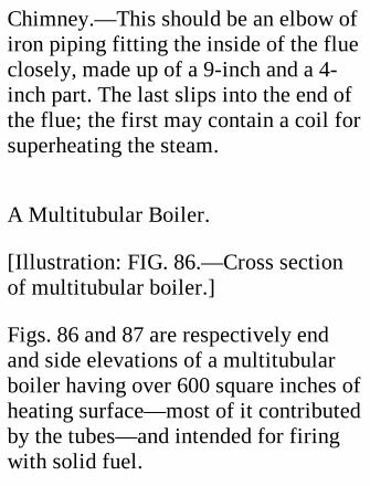
Chimney.—This should be an elbow ofiron piping fitting the inside of the flueclosely, made up of a 9-inch and a 4-inch part. The last slips into the end ofthe flue; the first may contain a coil forsuperheating the steam.
A Multitubular Boiler.
[Illustration: FIG. 86.—Cross sectionof multitubular boiler.]
Figs. 86 and 87 are respectively endand side elevations of a multitubularboiler having over 600 square inches ofheating surface—most of it contributedby the tubes—and intended for firingwith solid fuel.

The boiler has a main water-drum, A, 5inches in diameter and 18 inches long,and two smaller water-drums, B and C,2-1/2 by 18 inches, connected by twoseries of tubes, G and H, each setcomprising 20 tubes. The H tubes arenot exposed to the fire so directly asthe G tubes, but as they enter the maindrum at a higher point, the circulationis improved by uniting A to B and C atboth ends by large 1-inch drawn tubes,F. In addition, B and C are connectedby three 3/4-inch cross tubes, E, whichprevent the small drums spreading, andfurther equalize the water supply. A 1-1/2-inch drum, D, is placed on the topof A to collect the steam at a gooddistance from the water.

Materials.—In addition to 1-1/2 feet of5 by 3/32 inch solid-drawn tubing forthe main, and 3 feet of 2-1/2 by 1/16inch tubing for the lower drums, theboiler proper requires 22-1/2 feet of1/2-inch tubing, 19 inches of 3/4-inchtubing, 2-1/4 feet of 1-inch tubing, 1foot of 1-1/2-inch tubing, and ends ofsuitable size for the four drums.
[Illustration: FIG. 87.—Longitudinalsection of multitubular boiler.]
CONSTRUCTION.
[Illustration: FIG. 88.-Twoarrangements for tube holes in multi
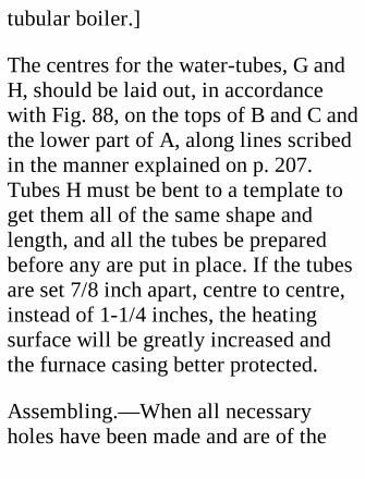
tubular boiler.]
The centres for the water-tubes, G andH, should be laid out, in accordancewith Fig. 88, on the tops of B and C andthe lower part of A, along lines scribedin the manner explained on p. 207.Tubes H must be bent to a template toget them all of the same shape andlength, and all the tubes be preparedbefore any are put in place. If the tubesare set 7/8 inch apart, centre to centre,instead of 1-1/4 inches, the heatingsurface will be greatly increased andthe furnace casing better protected.
Assembling.—When all necessaryholes have been made and are of the
correct size, begin by riveting andsilver-soldering in the ends of thedrums. Next fix the cross tubes, E,taking care that they and B and C formrectangles. Then slip the F, G, and Htubes half an inch into the main drum,and support A, by means of stripspassed between the G and H tubes, inits correct position relatively to B andC. The E tubes can now be pushed intoB and C and silver-soldered. Thesupports may then be removed, and thea and H tubes be got into position andsecured. Drum D then demandsattention. The connecting tubes, KK,should be silver-soldered in, as theboiler, if properly made, can be workedat pressures up to 100 lbs. per square
inch.
The casing is of 1/20-inch sheet iron,and in five parts. The back end must beholed to allow A, B, and C to project 1inch, and have a furnace-door opening,and an airway at the bottom, 5 incheswide and 1 inch deep, cut in it. Theairway may be provided with a flap, toassist in damping down the fire if toomuch steam is being raised. In the frontend make an inspection opening tofacilitate cleaning the tubes andremoving cinders, etc.
The side plates, m m, are bent as shownin Fig. 86, and bolted to a semicirculartop plate, n, bent to a radius of 6
inches. A slot, 1-1/2 inches wide and11-1/2 inches long, must be cut in thetop, n, to allow it to be passed overdrum D; and there must also be a 3 or3-1/2 inch hole for the chimney. Aplate, p, covers in D. A little plate, o, isslipped over the slot in n, and asbestosis packed in all round D. The interior ofthe end, side, and the top plates shouldbe lined with sheet asbestos held on bylarge tin washers and screw bolts. Toprotect the asbestos, movable ironsheets may be interposed on thefurnace side. These are replaced easilyif burnt away. The pieces m m are bentout at the bottom, and screwed down toa base-plate extending the whole lengthof the boiler.
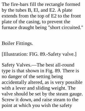
The fire-bars fill the rectangle formedby the tubes B, El, and E2. A plateextends from the top of E2 to the frontplate of the casing, to prevent thefurnace draught being "short circuited."
Boiler Fittings.
[Illustration: FIG. 89.-Safety valve.]
Safety Valves.—The best all-roundtype is that shown in Fig. 89. There isno danger of the setting beingaccidentally altered, as is very possiblewith a lever and sliding weight. Thevalve should be set by the steam gauge.Screw it down, and raise steam to thepoint at which you wish the safety
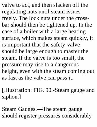
valve to act, and then slacken off theregulating nuts until steam issuesfreely. The lock nuts under the cross-bar should then be tightened up. In thecase of a boiler with a large heatingsurface, which makes steam quickly, itis important that the safety-valveshould be large enough to master thesteam. If the valve is too small, thepressure may rise to a dangerousheight, even with the steam coming outas fast as the valve can pass it.
[Illustration: FIG. 90.-Steam gauge andsiphon.]
Steam Gauges.—The steam gaugeshould register pressures considerably
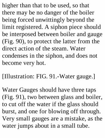
higher than that to be used, so thatthere may be no danger of the boilerbeing forced unwittingly beyond thelimit registered. A siphon piece shouldbe interposed between boiler and gauge(Fig. 90), to protect the latter from thedirect action of the steam. Watercondenses in the siphon, and does notbecome very hot.
[Illustration: FIG. 91.-Water gauge.]
Water Gauges should have three taps(Fig. 91), two between glass and boiler,to cut off the water if the glass shouldburst, and one for blowing off through.Very small gauges are a mistake, as thewater jumps about in a small tube.
When fitting a gauge, put packingsbetween the bushes and the glass-holders, substitute a piece of metal rodfor the glass tube, and pack the rodtightly. If the bushes are now sweatedinto the boiler end while thus directed,the gauge must be in line for the glass.This method is advisable in all cases,and is necessary if the boiler end is notperfectly flat.
Pumps.—Where a pump is used, thesupply should enter the boiler belowlow-water level through a non-returnvalve fitted with a tap, so that watercan be prevented from blowing backthrough the pump. As regards theconstruction of pumps, the reader is
referred to p. 164 and to Chapter XXII.
Filling Caps.—The filling cap shouldbe large enough to take the nozzle of agood-sized funnel with some room tospare. Beat the nozzle out of shape, togive room for the escape of the airdisplaced by the water.
The best form of filling cap has a self-seating ground plug, which, if properlymade, is steam-tight without anypacking. If needed, asbestos packingcan easily be inserted between plug andcap.
Mud-holes.—All but the smallestboilers should have a mud-hole andplug in the bottom at a point not
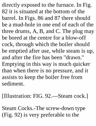
directly exposed to the furnace. In Fig.82 it is situated at the bottom of thebarrel. In Figs. 86 and 87 there shouldbe a mud-hole in one end of each of thethree drums, A, B, and C. The plug maybe bored at the centre for a blow-offcock, through which the boiler shouldbe emptied after use, while steam is up,and after the fire has been "drawn."Emptying in this way is much quickerthan when there is no pressure, and itassists to keep the boiler free fromsediment.
[Illustration: FIG. 92.—Steam cock.]
Steam Cocks.-The screw-down type(Fig. 92) is very preferable to the
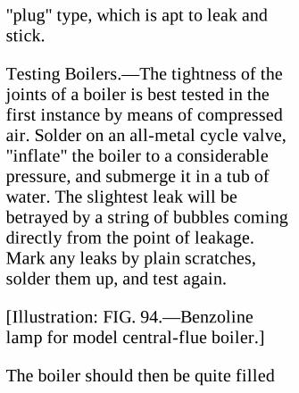
"plug" type, which is apt to leak andstick.
Testing Boilers.—The tightness of thejoints of a boiler is best tested in thefirst instance by means of compressedair. Solder on an all-metal cycle valve,"inflate" the boiler to a considerablepressure, and submerge it in a tub ofwater. The slightest leak will bebetrayed by a string of bubbles comingdirectly from the point of leakage.Mark any leaks by plain scratches,solder them up, and test again.
[Illustration: FIG. 94.—Benzolinelamp for model central-flue boiler.]
The boiler should then be quite filled

with cold water, and heated graduallyuntil the pressure gauge has risen toover the working pressure. There is norisk of an explosion, as the volume ofthe water is increased but slightly.
The third test is the most important andmost risky of all-namely, thatconducted under steam to a pressurewell above the working pressure.
In order to carry out the test withoutrisk, one needs to be able to watch thesteam-gauge from a considerabledistance, and to have the fire undercontrol. My own method is to set theboiler out in the open, screw down thesafety-valve so that it cannot lift, and
raise steam with the help of a blow-lamp, to which a string is attachedwherewith to pull it backwards along aboard. If the boiler is to be worked at50 lbs., I watch the steam gaugethrough a telescope until 100 lbs. isrecorded, then draw the lamp away.After passing the test, the boiler, whenpressure has fallen, say, 20 lbs., maysafely be inspected at close quarters forleaks.
This test is the only quite satisfactoryone, as it includes the influence of hightemperature, which has effects on themetal not shown by "cold" tests, suchas the hydraulic.
Do not increase your working pressurewithout first re-testing the boiler todouble the new pressure to be used.
Fuels.—For very small stationaryboilers the methylated spirit lamp isbest suited, as it is smell-less, and safeif the reservoir be kept well apart fromthe burner and the supply iscontrollable by a tap or valve. (See Fig.104.)
[Illustration: FIG. 95.-Paraffin burner
for vertical boiler.]
For medium-sized model boilers, andfor small launch boilers, benzoline orpetrol blow-lamps and paraffin stoveshave become very popular, as they doaway with stoking, and the amount ofheat is easily regulated by governingthe fuel supply. Fig. 94 is a sketch of ablow-lamp suitable for the horizontalboiler shown on pp. 204, and 206,while Fig. 95 shows a convenient formof paraffin stove with silent "Primus"burner, which may be used for ahorizontal with considerable furnacespace or for vertical boilers. In the caseof all these liquid fuel consumers, theamount of heat developed can be
increased by augmenting the number ofburners. Where a gas supply isavailable its use is to be recommendedfor small stationary boilers.
Solid Fuels.—The chief disadvantagesattaching to these are smoke andfumes; but as a solid fuel gives betterresults than liquid in a large furnace, itis preferred under certain conditions,one of them being that steam is notraised in a living room. Charcoal, coke,anthracite coal, and ordinary coalpartly burned are the fuels to use, thefire being started with a liberal supplyof embers from an open fire. Everysolid-fuel boiler should have a steam-blower in the chimney for drawing up
the fire; and if a really fierce blaze isaimed at, the exhaust from the engineshould be utilized for the samepurpose.
XIX. QUICK BOILINGKETTLES.
[Transcriber's note: Do not use leadsolder on articles associated withhuman or animal consumption.]
The principles of increasing the area ofheating surface in model boilers maybe applied very practically to the

common kettle. The quick-boilingkettle is useful for camping out, forheating the morning tea water of thevery early riser, and for the study"brew," which sometimes has to bemade in a hurry; and, on occasion, itwill be so welcome in the kitchen as toconstitute a very useful present to themistress of the house.
As the putting in of the tubes entailssome trouble, it is worth while to selecta good kettle for treatment. Get onethat is made of thick tinned sheet iron(cast-iron articles are unsuitable), oreven of copper, if you are intent onmaking a handsome gift which will lastindefinitely. The broad shallow kettle
is best suited for tubing, as it naturallyhas a fair heating surface, and itsbottom area gives room for insertingplenty of tubes. Also, the tubes can beof good length. Let us, therefore,assume that the kettle will be of at least8 inches diameter.
In Figs. 96 (a) and 96 (b) are showntwo forms of fire-tube kettles (a and b)and two of water-tube (c and d). Foruse over a spirit or Swedish petroleumstove the first two types are mostconvenient; the third will work well ona stove or an open fire; and the lastproves very efficient on an open fire.One may take it that, as a general rule,areas of heating surface being equal,
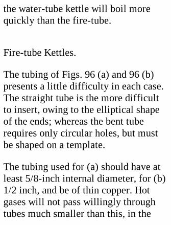
the water-tube kettle will boil morequickly than the fire-tube.
Fire-tube Kettles.
The tubing of Figs. 96 (a) and 96 (b)presents a little difficulty in each case.The straight tube is the more difficultto insert, owing to the elliptical shapeof the ends; whereas the bent tuberequires only circular holes, but mustbe shaped on a template.
The tubing used for (a) should have atleast 5/8-inch internal diameter, for (b)1/2 inch, and be of thin copper. Hotgases will not pass willingly throughtubes much smaller than this, in the
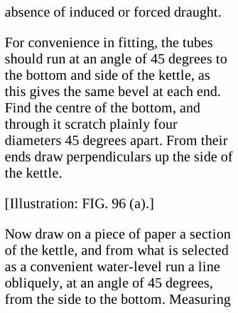
absence of induced or forced draught.
For convenience in fitting, the tubesshould run at an angle of 45 degrees tothe bottom and side of the kettle, asthis gives the same bevel at each end.Find the centre of the bottom, andthrough it scratch plainly fourdiameters 45 degrees apart. From theirends draw perpendiculars up the side ofthe kettle.
[Illustration: FIG. 96 (a).]
Now draw on a piece of paper a sectionof the kettle, and from what is selectedas a convenient water-level run a lineobliquely, at an angle of 45 degrees,from the side to the bottom. Measuring
off from this diagram, you canestablish the points in the side andbottom at which the upper and longerside of the tubes should emerge. Markthese off.
Next bevel off a piece of tubing to anangle of 45 degrees, cutting off roughlyin the first instance and finishing upcarefully with a file till the angle isexact. Solder to the end a piece of tin,and cut and file this to the preciseshape of the elliptical end. Detach byheating, scribe a line along its longestaxis, and attach it by a smallcountersunk screw to the end of aconvenient handle.
Place this template in turn on each ofthe eight radii, its long axis in line withit, being careful that the plate isbrought up to the marks mentionedabove, and is on the bottom corner sideof it. Scratch round plainly with a finesteel point.
To remove the metal for a tube hole, itis necessary to drill a succession ofalmost contiguous holes as near thescratch as possible without actuallycutting it. When the ring is completed,join the holes with a cold chisel heldobliquely. Then file carefully with around file, just not cutting the scratch.As the side of the hole nearest to thebottom corner should run obliquely to
enable the tube to pass, work this outwith the file held at an angle.
As soon as a pair of holes (one in thebottom, the other in the side) have beenmade, true up the side hole until apiece of tubing will run through it atthe correct angle. Then bevel off theend to 45 degrees and pass the tubethrough again, bringing the bevel upagainst the bottom hole from theinside. If it is a trifle difficult to pass,bevel off the edge slightly on the insideto make a fairly easy driving fit. (Takecare not to bulge the bottom of thekettle.) Mark off the tube beyond theside hole, allowing an eighth of an inchextra. Cut at the mark, and number tube

and hole, so that they may be pairedcorrectly later on.
When all the tubes are fitted, "tin" theends with a wash of solder beforereturning them to their holes. If there isa gap at any point wide enough to letthe solder run through, either beat outthe tube from the inside into contact,or, if this is impracticable, place a bitof brass wire in the gap. Use powderedresin by preference as flux for an ironkettle, as it does not cause the rustingproduced by spirit of salt. If the latteris used, wipe over the solder with astrong ammonia or soda solution, inorder to neutralize the acid.
As the hot gases may tend to escape tooquickly through large tubes, it is wellto insert in the upper end of each asmall "stop," x—a circle of tin with anarc cut away on the bottom side. Toencourage the gases to pass up thetubes instead of along the bottom, aring of metal, y, may be solderedbeyond the bottom holes, if an oil orspirit stove is to be used. This ringshould have notches cut along thekettle edge, so as not to throttle theflame too much.
[Illustration: FIG. 96—(b), (c), and(d).]
As the tubes for these require bending
to shape in each case, the three typesmay be grouped together. The tubes ofc and d, which require bending tosomewhat sharp curves, may be of 3/8-inch internal diameter. In the last twocases the direction of the water travelis shown. The up-flow end, whichprojects farther through the bottomthan the down-flow, is nearer thecentre, where, if a gas stove is used, theheat is more intense than at thecircumference of the bottom. (Note.-Iftype c is for use on a three-supportstove, increase the number of tubes to9, equally spaced, 40 degrees apart, sothat the kettle may be adjusted easily.)
The copper tubing should be annealed

or softened by heating to a dull red andplunging in cold water. Cut a woodentemplate of the exact outline of theinside line of the shape that the tube isto assume, and secure this firmly to aboard. Fill the tube with melted resin,to prevent, as much as possible,"buckling" or flattening on the curves.The tube must be kept up to thetemplate by a stop of hard wood, at theend at which bending commences.Don't cut the tube into lengths beforebending, as short pieces are moredifficult to handle. When a piecesufficient for a tube has been bent, cutit oft, and remove the resin by heating.
The fitting of the tubes is an easy
matter, as the holes are circular. Pairoff a tube with its holes and number it.A fluted reamer will be foundinvaluable for enlarging them to thecorrect size. Tin all tubes at pointswhere they are to be attached to thekettle.
In Fig. 96 (c) and (d) care should betaken to make all the tubes project thesame distance, so that the kettle may belevel when resting on them.
XX. A HOT-AIR ENGINE.
The pretty little toy about to be
described is interesting as a practicalapplication to power-producingpurposes of the force exerted byexpanding air. It is easy to make, and,for mere demonstration purposes, hasan advantage over a steam-engine ofthe same size in that it can be setworking in less than a minute, and willcontinue to act as long as a small spiritflame is kept burning beneath it; itcannot explode; and its construction isa simpler matter than the building of asteam-engine.
[Illustration: FIG. 97.—Verticalsection of hot-air engine.]
Principles of the Hot-air Engine.—Fig.
97 gives a sectional view of the engine.The place of what would be the boilerin a steam-engine of similar shape istaken by an air chamber immediatelyabove the lamp, and above that is achamber through which cold watercirculates. In what we will call theheating chamber a large piston, knownas the displacer, is moved up and downby a rod D and a connecting rod CR1.This piston does not touch the sides ofthe chamber, so that the bulk of the airis pushed past it from one end of thechamber to the other as the pistonmoves. When the displacer is in theposition shown—at the top of its stroke—the air is heated by contact with thehot plate C, and expands, forcing up the

piston of the power cylinder, seen onthe left of the engine. (The power crankand the displacer crank are, it should bementioned, set at right angles to oneanother.) During the second half of thepower stroke the displacer is moveddownwards, causing some of the air topass round it into contact with the coldplate D. It immediately contracts, andreduces the pressure on the powerpiston by the time that the piston hasfinished its stroke. When the powerpiston has reached the middle of itsdownward stroke, the displacer is at itslowest position, but is halfway up againwhen the power piston is quite down.The air is once again displaceddownwards, and the cycle begins anew.
The motive power is, therefore,provided by the alternate heating andcooling of the same air.
Construction.—The barrel and supportswere made out of a single piece of thinbrass tubing, 2-7/16 inch internaldiameter and 5-5/8 inch long. Theheating end was filed up true, the othercut and filed to the shape indicated inFig. 98 by dotted lines. The markingout was accomplished with the help ofa strip of paper exactly as wide as thelength of the tube, and as long as thetube's circumference. This strip had aline ruled parallel to one of its longeredges, and 2-1/2 inches from it, andwas then folded twice, parallel to a

shorter edge. A design like the shadedpart of Fig. 98 was drawn on an endfold, and all the four folds cut throughalong this line with a pair of scissors.When opened out, the paper appearedas in Fig. 98.
[Illustration: FIG. 98.]
We now—to pass into the present tense—wrap this pattern round the tube andscratch along its edges. The metal isremoved from the two hollows bycutting out roughly with a hack sawand finishing up to the lines with a file.
The next things to take in hand are thedisplacer rod D and the guide tube inwhich it works. These must make so
good a fit that when slightly lubricatedthey shall prevent the passage of airbetween them and yet set up very littlefriction. If you cannot find a piece ofsteel rod and brass tubing which fitclose enough naturally, the onlyalternative is to rub down a rod,slightly too big to start with, until itwill just move freely in the tube. Thisis a somewhat tedious business, butemery cloth will do it. The rod shouldbe 3-3/8 inches, the tube 2-1/8 inches,long. I used rod 3/16 inch in diameter;but a smaller rod would do equallywell.
[Illustration: FIG. 99.]

The two plates, A and B, are nextprepared by filing or turning down thinbrass[1] discs to a tight fit. (Note.—Forturning down, the disc should besoldered centrally to a piece ofaccurately square brass rod, which canbe gripped in a chuck. I used aspecially-made holder like that shownin Fig. 99 for this purpose.)
[Footnote 1: Thin iron plate has thedisadvantage of soon corroding.]
When a good fit has been obtained,solder the two discs together so thatthey coincide exactly, and bore acentral hole to fit the guide tubetightly. Before separating the plates
make matching marks, so that the sameparts may lie in the same directionwhen they are put in position. This willensure the guide tube being parallel tothe barrel.
The power cylinder is a piece of brasstubing 2 inches long and of 7/8-inchinternal diameter. The piston is of 7/8-inch tubing, fitting the cylinder easily,and thick enough to allow a shallowpacking recess to be turned in theoutside. Brass washers turned or filedto size form the ends of cylinder andpiston. The connecting rod CR2 is apiece of strip brass, 3-3/16 inches long,between centres of holes. This hadbetter be cut off a bit long in the first
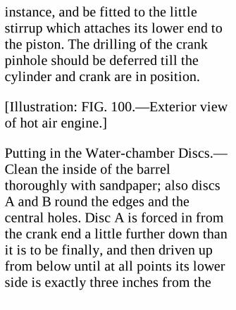
instance, and be fitted to the littlestirrup which attaches its lower end tothe piston. The drilling of the crankpinhole should be deferred till thecylinder and crank are in position.
[Illustration: FIG. 100.—Exterior viewof hot air engine.]
Putting in the Water-chamber Discs.—Clean the inside of the barrelthoroughly with sandpaper; also discsA and B round the edges and thecentral holes. Disc A is forced in fromthe crank end a little further down thanit is to be finally, and then driven upfrom below until at all points its lowerside is exactly three inches from the
bottom edge of the barrel. Disc B isthen forced up 1-1/2 inches from thebottom end. The guide tube— whichshould have been cleaned—havingbeen driven into place, solder is run allround the joints. If the barrel is heatedover a spirit lamp, this operation isperformed very quickly. ("Tinol"soldering paste is recommended.)Before soldering in B, drill a smallhole in the barrel between A and B toallow the air to escape.
Attaching the Cylinder.—Scratch abold line through the centre of one ofthe crank holes to the bottom of thebarrel, to act as guide. Drill a 5/32-inchhole in the barrel on this line just
below plate B, and a similar hole in thebottom of the cylinder. (The cylinderend should be put in positiontemporarily while this is done toprevent distortion.) Flatten down thecylinder slightly on the line of the hole,so that it may lie snugly against thebarrel, and clean the outside of thebarrel. Lay the cylinder against thebarrel with the holes opposite oneanother, and push a short piece of woodthrough to exclude solder from theholes and keep the holes in line. Half adozen turns of fine wire strained tightlyround cylinder and barrel will hold thecylinder in place while soldering isdone with a bit or lamp. The end of thecylinder should then be made fast.

The Displacer.—This is a circularblock of wood—well dried beforeturning—5/8 inch thick and 3/32 inchless in diameter than the inside of thebarrel. The rod hole in it should bebored as truly central as possible. Ahole is drilled edgeways through theblock and through the rod to take a pinto hold the two together. To prevent itsplitting with the heat, make a coupleof grooves in the sides to accommodatea few turns of fine copper wire, thetwisted ends of which should be beatendown flush with the outside of theblock. The bottom of the block isprotected by a disc of asbestos cardheld up to the wood by a disc of tinnailed on.
The Crank Shaft and Crank.—Thecentral crank of the crank shaft—thatfor the displacer—has a "throw" of 1/4inch, as the full travel of the displaceris 1/2 inch. If the bending of a rod tothe proper shape is beyond the reader'scapacity, he may build up a crank inthe manner shown in Fig. 101. Holesfor the shaft are bored near the tops ofthe supports, and the shaft is put inplace. After this has been done, smokethe shaft in a candle flame and soldertwo small bits of tubing, or boredpieces of brass, to the outside of thesupports to increase the length of thebearing. The power-crank boss is a 1-1/2-inch brass disc. This crank has a"throw" of 1/2 inch.
[Illustration: FIG. 101.-Details of built-up crank.]
Connecting Rods.—Put a piece of card1/16 inch thick in the bottom of thecylinder and push the piston home.Turn the power crank down and markoff the centre of the hole for the crankpin in the connecting rod CR2. Solder apiece of strip brass on each side of therod at this point; measure again, anddrill.
The top of the displacer rod D is nowfiled flat on two sides and drilled. Slipa ring 1/16 inch thick over the rod andpush the rod upwards through the guidetube till the displacer can go no farther.
Turn the displacer crank up andmeasure from the centre of the hole inthe rod to the centre of the crank. Thetop of the connecting rod should befiled to fit the under side of the crank,against which it should be held by alittle horseshoe-shaped strap pinned on.(Fig. 102). (Be sure to remove the ringafter it has served its purpose.)
The Water Circulation.—The waterchamber is connected by two rubbertubes with an external tank. In Fig. 97the cooling water tank is shown, forillustrative purposes, on the fly-wheelside of the engine, but can be placedmore conveniently behind the engine,as it were. Two short nozzles, E1 and
E2, of 1/4-inch tube are soldered intothe water chamber near the top andbottom for the rubber pipes to beslipped over, and two more on thewater tank. For the tank one may selecta discarded 1 lb. carbide tin. Cut off thetop and solder on a ring of brass wire;make all the joints water-tight withsolder, and give the tin a couple ofcoatings of paint inside and outside.
[Illustration: FIG. 102.]
Closing the Hot-air Chamber.—Whenall the parts except the lamp chamberhave been prepared, assemble them tomake sure that everything is in order.The lower end of the hot-air chamber
has then to be made air-tight. Solderingis obviously useless here, as the heat ofthe lamp would soon cause the solderto run, and it is impossible to make abrazed joint without unsoldering thejoints in the upper parts of the engine. Iwas a bit puzzled over the problem, andsolved it by means of the lower part ofan old tooth-powder box stamped outof a single piece of tin. This made atight fit on the outside of the barrel,and as it was nearly an inch deep, Iexpected that if it were driven home onthe barrel and soldered to it the jointwould be too near the water chamber tobe affected by the lamp. This hasproved to be the case, even when thewater is nearly at boiling point. If a
very close-fitting box is not procurable,the space between box and barrel mustbe filled in with a strip of tin cut off tothe correct length.
The Lamp Chamber.—Cut out a stripof tin 4 inches wide and 1 inch longerthan the circumference of the lowerend of the hot-air chamber. Scratch aline 1/2 inch from one of the sides, aline 3/4 inch from the other, and a line1/2 inch from each of the ends.
A lamp hole is cut in the centre, andventilation holes 1 inch apart, as shownin Fig. 103. If the latter holes are madesquare or triangular (base uppermost),and the metal is cut with a cold chisel
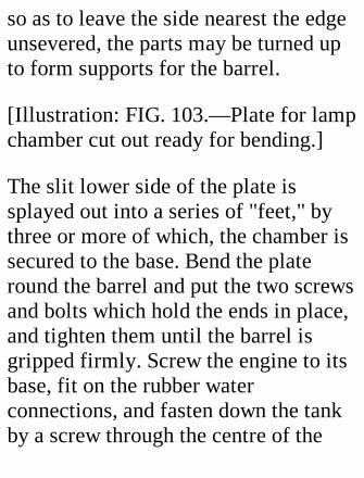
so as to leave the side nearest the edgeunsevered, the parts may be turned upto form supports for the barrel.
[Illustration: FIG. 103.—Plate for lampchamber cut out ready for bending.]
The slit lower side of the plate issplayed out into a series of "feet," bythree or more of which, the chamber issecured to the base. Bend the plateround the barrel and put the two screwsand bolts which hold the ends in place,and tighten them until the barrel isgripped firmly. Screw the engine to itsbase, fit on the rubber waterconnections, and fasten down the tankby a screw through the centre of the
bottom. The screw should pass througha brass washer, between which and thetank should be interposed a rubberwasher to make a water-tight joint.
The Lamp.—The lamp shown in Fig.104 was made out of a truncated brasselbow, a piece of 5/16-inch brass tube,and a round tin box holding about 1/3-pint of methylated spirit. A tapinterposed between the reservoir andburner assists regulation of the flame,and prevents leakage when the lamp isnot in use.
Running the Engine.—The power anddisplacer cranks must be set exactly atright angles to one another, and the
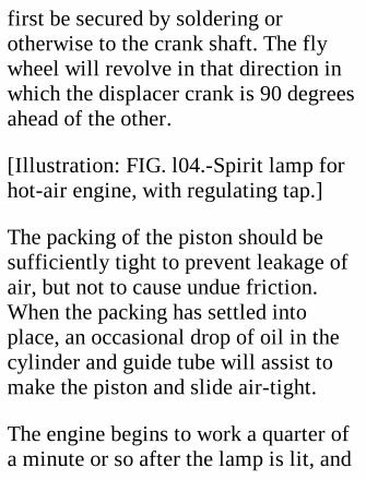
first be secured by soldering orotherwise to the crank shaft. The flywheel will revolve in that direction inwhich the displacer crank is 90 degreesahead of the other.
[Illustration: FIG. l04.-Spirit lamp forhot-air engine, with regulating tap.]
The packing of the piston should besufficiently tight to prevent leakage ofair, but not to cause undue friction.When the packing has settled intoplace, an occasional drop of oil in thecylinder and guide tube will assist tomake the piston and slide air-tight.
The engine begins to work a quarter ofa minute or so after the lamp is lit, and
increases its speed up to a certainpoint, say 300 revolutions per minute.When the water becomes very hot itmay be changed. The power might beapplied, through demultiplying gear, toa small pump drawing water from thebottom of the tank and forcing itthrough the water chamber and a bent-over stand pipe into the tank again.This will help to keep the water cool,and will add to the interest of theexhibit by showing "work being done."
XXI. A WATER MOTOR.

FIG. 105 is a perspective view of asimple water motor which costs littleto make, and can be constructed byanybody able to use carpenter's toolsand a soldering iron. It will serve todrive a very small dynamo, or do otherwork for which power on a small scaleis required. A water supply giving apressure of 40 lbs. upwards per squareinch must be available.
We begin operations by fashioning thecase, which consists of three mainparts, the centre and two sides, heldtogether by brass screws. For thecentre, select a piece of oak 1 inchthick. Mark off a square, 7 inches onthe side; find the centre of this, and
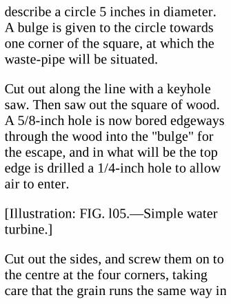
describe a circle 5 inches in diameter.A bulge is given to the circle towardsone corner of the square, at which thewaste-pipe will be situated.
Cut out along the line with a keyholesaw. Then saw out the square of wood.A 5/8-inch hole is now bored edgewaysthrough the wood into the "bulge" forthe escape, and in what will be the topedge is drilled a 1/4-inch hole to allowair to enter.
[Illustration: FIG. l05.—Simple waterturbine.]
Cut out the sides, and screw them on tothe centre at the four corners, takingcare that the grain runs the same way in
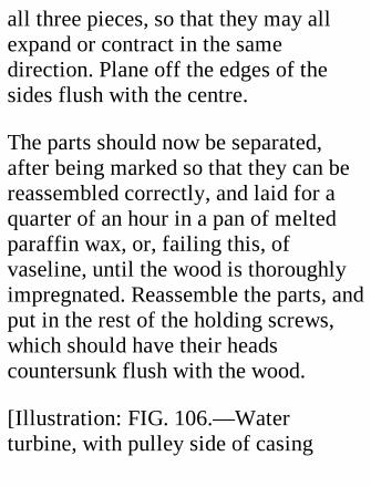
all three pieces, so that they may allexpand or contract in the samedirection. Plane off the edges of thesides flush with the centre.
The parts should now be separated,after being marked so that they can bereassembled correctly, and laid for aquarter of an hour in a pan of meltedparaffin wax, or, failing this, ofvaseline, until the wood is thoroughlyimpregnated. Reassemble the parts, andput in the rest of the holding screws,which should have their headscountersunk flush with the wood.
[Illustration: FIG. 106.—Waterturbine, with pulley side of casing
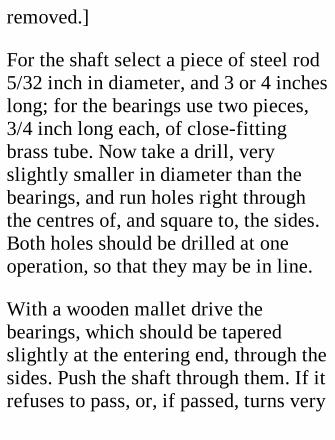
removed.]
For the shaft select a piece of steel rod5/32 inch in diameter, and 3 or 4 incheslong; for the bearings use two pieces,3/4 inch long each, of close-fittingbrass tube. Now take a drill, veryslightly smaller in diameter than thebearings, and run holes right throughthe centres of, and square to, the sides.Both holes should be drilled at oneoperation, so that they may be in line.
With a wooden mallet drive thebearings, which should be taperedslightly at the entering end, through thesides. Push the shaft through them. If itrefuses to pass, or, if passed, turns very
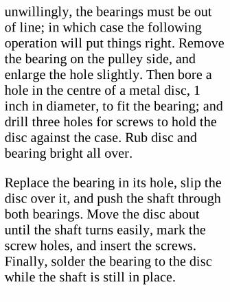
unwillingly, the bearings must be outof line; in which case the followingoperation will put things right. Removethe bearing on the pulley side, andenlarge the hole slightly. Then bore ahole in the centre of a metal disc, 1inch in diameter, to fit the bearing; anddrill three holes for screws to hold thedisc against the case. Rub disc andbearing bright all over.
Replace the bearing in its hole, slip thedisc over it, and push the shaft throughboth bearings. Move the disc aboutuntil the shaft turns easily, mark thescrew holes, and insert the screws.Finally, solder the bearing to the discwhile the shaft is still in place.
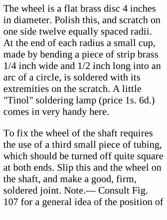
The wheel is a flat brass disc 4 inchesin diameter. Polish this, and scratch onone side twelve equally spaced radii.At the end of each radius a small cup,made by bending a piece of strip brass1/4 inch wide and 1/2 inch long into anarc of a circle, is soldered with itsextremities on the scratch. A little"Tinol" soldering lamp (price 1s. 6d.)comes in very handy here.
To fix the wheel of the shaft requiresthe use of a third small piece of tubing,which should be turned off quite squareat both ends. Slip this and the wheel onthe shaft, and make a good, firm,soldered joint. Note.— Consult Fig.107 for a general idea of the position of
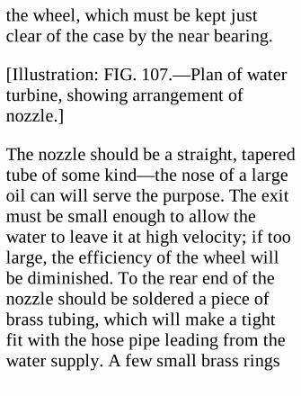
the wheel, which must be kept justclear of the case by the near bearing.
[Illustration: FIG. 107.—Plan of waterturbine, showing arrangement ofnozzle.]
The nozzle should be a straight, taperedtube of some kind—the nose of a largeoil can will serve the purpose. The exitmust be small enough to allow thewater to leave it at high velocity; if toolarge, the efficiency of the wheel willbe diminished. To the rear end of thenozzle should be soldered a piece ofbrass tubing, which will make a tightfit with the hose pipe leading from thewater supply. A few small brass rings
soldered round this piece will preventthe hose blowing off if well wired onthe outside.
Now comes the boring of the hole forthe nozzle. Fig. 106 shows the line itshould take horizontally, so that thewater shall strike the uppermost bucketjust below the centre; while Fig. 107indicates the obliquity needed to makethe stream miss the intervening bucket.A tapered broach should be used toenlarge the hole gradually till thenozzle projects sufficiently. If the lineis not quite correct, the tip should bebent carefully in the direction required.One must avoid distorting the orifice,which should be perfectly circular;
clean it out with a small twist drill ofthe proper size.
A brass elbow, which may bepurchased for a few pence, should bedriven into the waste hole, and a smallshield be nailed under the air hole. Acouple of screwed-on cross pieces arerequired to steady the motor sidewaysand raise the elbow clear of the ground.
The motor may be geared direct to avery small dynamo, if the latter isdesigned to run at high speeds. If ageared-down drive is needed, a smallpulley—such as is used for blinds, andmay be bought for a penny—should beattached to the shaft, and a bootlace be

employed as belt. Avoid overloadingthe wheel, for if it is unable to run at ahigh speed it will prove inefficient.
[Illustration: FIG. l08.-Water motorworking a photographic dish-rocker.]
Lubrication.—The water will keep thebearings cool, but the bearings shouldbe well lubricated. The mostconvenient method of effecting this isto bore holes in the bearings, and fromthem run small pipes to an oil reservoiron the top of the case (as in Fig. 70),where they are fed on the siphonprinciple through strands of worsted.
Alternative Construction.—If an all-metal case is preferred, the reader
might utilize the description given of asteam turbine on pp. 170-178. Thedetails there given will apply to wateras well as steam, the one exceptionbeing that a nozzle of the kinddescribed above must be substituted forthe steam pipe and small ports.
XXII. MODEL PUMPS.
Every steam boiler which has to run forlong periods and evaporateconsiderable quantities of water shouldbe in connection with a pump capableof forcing water in against the highest

pressure used. On a previous page (p.158) we have described a force pumpdriven directly off the crank shaft of anengine. As the action of this isdependent on the running of the engine,it is advisable, in cases where theboiler may have to work an engine notprovided with a pump of its own, toinstall an independent auxiliary pumpoperated by hand or by steam, and ofconsiderable capacity, so that in anemergency water may be suppliedquickly.
[Illustration: FIG. l09.-Vertical sectionof force pump.]
Making a Hand pump.—Fig. 109 shows

the details of a hand pump which iseasy to make. The barrel is a length ofbrass tubing; the plunger a piece ofbrass or preferably gun-metal rod,which fits the tube closely, but workseasily in it. The gland at the top of thebarrel, E, is composed of a piece, D, ofthe same tubing as the barrel, sliding ina collar, C, soldered to E. The bottomof D and top of E are bevelled to forcethe packing against the plunger. Theplates A and B, soldered to D and Crespectively, are drawn together bythree or more screws. A brass door-knob makes a convenient top for theplunger. When the knob touches A, thebottom of the plunger must not comelower than the top of the delivery pipe,
lest the water flow should be impededand the valve, V, injured. Round off theend of the plunger, so that it may bereplaced easily and withoutdisarranging the packing if pulled outof the pump.
The valves are gun-metal balls, forwhich seats have been prepared byhammering in steel cycle balls of thesame size. Be careful to select ballsconsiderably larger than the bore of thepipes on which they rest, to avoid allpossibility of jamming. An eighth of aninch or so above the ball, cross wiresshould be soldered in to prevent theball rising too far from its seat.
[Illustration: FIG. 110.]
A convenient mounting for a handpump is shown in Fig. 110. The plate,F, of the pump is screwed to a woodenbase resting on a framework of bentsheet zinc, which is attached to thebottom of a zinc water tray. Thedelivery pipe, G, will be protectedagainst undue strains if secured by astrap to the side of the wooden base.
The same pump is easily adapted to beworked by a lever, which makes thework of pumping easier. Fig. 111 givesdetails of the top of the plunger and thelinks, B. A slot must be cut in theplunger for the lever, A, to pass
through, and the sides bored for a pivotpin. The links are straddled (see sketchof end view) to prevent the back end ofthe lever wobbling from side to side.
[Illustration: FIG. 111.—Details oflever for force pump.]
A Steam Pump.—The pump illustratedin Fig. 112 belongs to what is probablythe simplest self-contained type, as nofly wheel, crank, or eccentric is neededfor operating the valve.
The steam cylinder and the pump areset in line with one another (in the caseshown, horizontally), and half as farapart again as the stroke of thecylinder. The plunger is either a
continuation of the piston rod, orattached to it.
[Illustration: FIG. 112—View of steampump, showing details.]
An arm, S, fixed at right angles to thepiston rod, has a forked end whichmoves along the rod. This rod isconnected with the slide valve throughthe rocking arm, R1 and the rod, R2.On it are two adjustable stops, T1 T2,which S strikes alternately towards theend of a stroke, causing the valve toshift over and expose the other side ofthe piston to steam pressure. Theabsence of the momentum of a flywheel makes it necessary for the thrust
exerted by the piston to beconsiderably greater than the backpressure of the water, so that themoving parts may work with a velocitysufficient to open the valve. If thespeed falls below a certain limit, thevalve opens only part way, the speedfalls, and at the end of the next strokethe valve is not shifted at all.
The diameter of the plunger must bedecided by the pressure against whichit will have to work. For boiler feedingit should not exceed one-third that ofthe piston; and in such case the pistonrod and plunger may well be one.
A piston valve, being moved more
easily than a box valve, is better suitedfor a pump of this kind, as frictionshould be reduced as much as possible.
CONSTRUCTION.
The cylinder will not be described indetail, as hints on making a slide-valvecylinder have been given on earlierpages. The piston rod should be threetimes as long as the stroke of thecylinder, if it is to serve as pumpplunger; and near the pump end anannular groove must be sunk to take apacking.
The pump, if designed to work
horizontally, will have the valvesarranged like the pump illustrated inFig. 65; if vertically, like the pumpshown in Fig. 109. Both suction anddelivery pipes should be of ample size,as the pump works very fast. The pumpis mounted on a foot, F, made byturning up the ends of a piece of brassstrip, and filing them to fit the barrel.
The bed can be fashioned out of stoutsheet brass or zinc. Let it be of amplesize to start with, and do not cut itdown until the pump is complete. Rulea centre line for cylinder and pump,and mount the cylinder. Pull out thepiston rod plunger as far as it will go,and slip the pump barrel on it. The foot
of the pump must then be brought tothe correct height by filing andspreading the ends until the plungerworks quite easily in the pump, whenthis is pressed down firmly against thebed. When adjustment is satisfactory,mark the position of the foot on thebed, solder foot to barrel, and drill andtap the foot for the holding-downscrews. Don't forget that the distancebetween pump and cylinder gland mustbe at least 1-1/3 times the stroke.
The valve motion can then be taken inhand. Cut off for the guides, G1 G2,two pieces of stout brass strip, 2-1/2inches long and 3/4 inch wide. Laythem together in a vice, and bore the
holes (Fig. 113) 1-1/4 inches apart,centre to centre, for the 1/8-inch rods,R1 R2. The feet are then turned overand a third hole bored in G1, midwaybetween those previously made, to takethe end of the support, PP, of therocking lever.
[Illustration: FIG. 113.—End view ofstriking mechanism of steam pump.]
Screw G1 G2 down to the bedplate, 3/4inch away from the cylinder centreline. G1 is abreast of the mouth of thepump, G2 about half an inch forward ofthe end of the cylinder.
The striker, S, is a piece of brass stripsoldered to 1/2 inch of tubing fitting
the piston rod. (See Fig. 113.) Itslength is decided by running a rodthrough the upper holes in G1 G2,allowance being made for the notch inthe end. The collar is tapped for twoscrews, which prevent S slipping on thepiston rod. The rods for R1 R2 are nowprovided with forks, made by cuttingand filing notches in bits of brasstubing. The notches should be half asdeep again as the rocking lever is wide,to give plenty of room for movement.Solder the forks to the rods, and put therods in place in the guides, with theforks as far away from G1 as the travelof the slide valve. Then measure to getthe length of the rocking lever support.One end of this should be filed or
turned down to fit the hole drilled forit; the other should be slotted to fit thelever accurately.
The rocking lever, RL, which should beof steel, is slotted at each end to slideon the pins in the forks, and bored forthe pivot pin, which, like those in theforks, should be of hardened steel wire.Assemble the rocking lever in itssupport and the rod forks, and solder onthe support.
To the back end of R2 solder a steelplate, A, which must be bored for thepin in the valve fork, after the correctposition has been ascertained bycareful measurement.

The stops, T1 T2, are small, adjustablecollars, kept tightly in place onR1 by screws.
Setting the Striker.—Assemble all theparts. Pull out the piston rod as far as itwill go, and push the slide valve rightback. Loosen the striker and theforward stop, and slide them along incontact until the striker is close to thepump. Tighten up their screws. Thenpush the piston rod fully in, draw thevalve rod fully out, and bring the rearstop up against the striker, and make itfast. Each stop may now be moved 1/16inch nearer to a point halfway betweenthem to cause "cushioning" of thepiston, by admitting steam before the
stroke is quite finished.
A pump made by the author on thisprinciple, having a 1-1/4 inch strokeand a 1/2-inch bore, will deliver waterat the rate of half a gallon per minuteagainst a head of a few feet.
Note.—To steady the flow and prevent"water hammer," a small air-chambershould be attached to the delivery pipe.
An Alternative Arrangement.—If thereader prefers a steam pump which willwork at slow speeds, and be available,when not pumping, for drivingpurposes, the design may be modifiedas shown diagrammatically in Fig. 114.The striker becomes a cross head, and
is connected by a forked rod passing oneach side of the pump with the crank ofa fly wheel overhanging the base. Thevalve is operated in the ordinarymanner by an eccentric on thecrankshaft. The steadying effect of thefly wheel and the positive action of thevalve make it possible to use a largerpump plunger than is advisable withthe striking gear. With a pump pistonof considerably greater diameter thanthe piston rod, the pump may be madedouble-acting, a gland being fitted atthe front end for the piston rod to workthrough, and, of course, a second set ofvalves added.
[Illustration: Fig. 114.—Plan of steam
pump with fly wheel.]
A SUGGESTION.
For exhibition purposes a small, easilyrunning, double-action pump might beworked by the spindle of agramophone. A crank of the properthrow and a connecting rod must beprovided. Both delivery pipes feed,through an air-chamber, a fountain inthe centre of a bowl, the waterreturning through an overflow to thesource of supply, so that the samewater may be used over and over again.
XXIII. KITES.
Plain Rectangular Box Kites.—Theplain box kite is easy to make and agood flier. Readers should try theirhands on it before attempting morecomplicated models.
Lifting pressure is exerted only on thesides facing the wind, but the othersides have their use in steadying thekite laterally, and in holding in thewind, so that they justify their weight.
Proportions of Box.—Each box haswind faces one and a third times aslong as the sides, and the vertical depthof the box is about the same as its fore
and aft dimensions. That is, the ends ofthe boxes are square, and the windfaces oblong, with one-third as mucharea again as the ends. Little advantageis to be gained from making the boxesproportionately deeper than this. Thedistance between the boxes should beabout equal to the depth of each box.
CONSTRUCTION.
After these general remarks, we mayproceed to a practical description ofmanufacture, which will apply to kitesof all dimensions. It will be prudent tobegin on small models, as requiringsmall outlay.
Having decided on the size of yourkite, cut out two pieces of material aswide as a box is to be deep, and as longas the circumference of the box plus aninch and a half to spare. Machine stitch5/8 inch tapes along each edge, usingtwo rows of stitching about 1/8 inchfrom the edges of the tape. Then doublethe piece over, tapes inside, andmachine stitch the ends together, threequarters of an inch from the edge.Note.—All thread ends should be tiedtogether to prevent unravelling, andends of stitching should be hand-sewnthrough the tape, as the greatest strainfalls on these points.
The most convenient shape for the rods
is square, as fitting the corners andtaking tacks most easily. The sectionalsize of the rods is governed by thedimensions of the kite, and to a certainextent by the number of stretchersused. If four stretchers are employed ineach box, two near the top and two nearthe bottom, the rods need not be sostout as in a case where only a singlepair of central stretchers is preferred.
Lay the two boxes flat on the floor, inline with one another, and the joins atthe same end. Pass two rods through,and arrange the boxes so that the outeredges are 1/2 inch from the ends of therods. (These projections protect thefabric when the kite strikes the
ground).
Lay the rods on one corner, so that thesides make an angle of 45 degrees withthe floor, pull the boxes taut—becareful that they are square to the rods—and drive three or four tacks througheach end of the box into the rods. Thenturn them over and tack the other sidessimilarly. Repeat the process with theother rods after measuring to get thedistances correct.
The length of the stretchers is foundapproximately by a simple arithmeticalsum, being the square root of the sumof the squares of the lengths of twoadjacent sides of the box. For example,
if each box is 20 by 15 inches, thediagonal is the square root of (20squared plus 15 squared) = square rootof 625 = 25 inches. The space occupiedby the vertical rods will about offsetthe stretch of the material, but to be onthe safe side and to allow for thenotches, add another half-inch forsmall kites and more proportionatelyfor large ones. It is advisable to testone pair of stretchers before cuttinganother, to reduce the effect ofmiscalculations.
The stretcher notches should be deepenough to grip the rods well andprevent them twisting, and one musttake care to have those on the same
stretcher exactly in line, otherwise oneor other cannot possibly "bed"properly. A square file is useful forshaping the notches.
Ordinarily stretchers do not tend to fallout, as the wind pressure puts extrastrain on them and keeps them up tight.But to prevent definitely anymovement one may insert screw eyesinto the rods near the points at whichthe stretchers press on them, and othereyes near the ends of the stretchers totake string fastenings. Theseattachments will be found useful forgetting the first pair of stretchers intoposition, and for preventing thestretchers getting lost when the kite is

rolled up.
The bridle is attached to four eyesscrewed into the rods near the tops ofthe boxes. (See Fig. 118.) The top andbottom elements of the bridle must bepaired off to the correct length; the topbeing considerably shorter than thebottom. All four parts may be attachedto a brass ring, and all should be tautwhen the ring is pulled on. The exactadjustment must be found byexperiment. In a very high wind it isadvisable to shorten the top of thebridle if you have any doubt as to thestrength of your string, to flatten theangle made by the kite with the wind.

[Illustration: FIG. 115.—Details ofstretcher attachment for diamond-shaped box kites.]
Diamond Box Kites.—In another typeof box kite the boxes have four equalsides, but the boxes are rhombus-shaped, as in Fig. 116, the longdiagonal being square to the wind, andthe bridle attached at the front corner.
For particulars of design andconstruction I am much indebted toMr. W. H. Dines, F.R.S., who has usedthe diamond box kite for hismeteorological experiments to carryregistering meteorographs severalthousands of feet into the air.
The longitudinal sticks used at thecorners have the section shown in Fig.115. They are about four times as wideat the front edge, which presses againstthe fabric, as at the back, and theirdepth is about twice the greater width.This shape makes it easy to attach theshorter stretchers, which have theirends notched and bound to preventsplitting.
[Illustration: FIG. 116.—Plan ofdiamond box kite, showingarrangement of stretchers.]
Fig. 117 is a perspective diagram of akite. The sail of each box measuresfrom top to bottom one-sixth the total
circumference of the box, or, to expressthe matter differently, each face of thebox is half as long again as its depth.The distance separating the boxes isequal to the depth of a box.
The sides of a box make angles of 60degrees and 120 degrees with oneanother, the depth of the spaceenclosed from front to back being thesame as the length of a side. With theseangles the effective area of the sails isabout six-sevenths of the total area.Therefore a kite of the dimensionsgiven in Fig. 117 will have an effectivearea of some thirty square feet.
[Illustration: FIG. 117.—Diamond box
kite in perspective. Ties are indicatedby fine dotted lines.]
The long stretchers pass through holesin the fabric close to the sticks, and areconnected with the sticks by stouttwine. Between stretcher and stick isinterposed a wedge-shaped piece ofwood (A in Fig. 115), which preventsthe stick being drawn out of line. Thismethod of attachment enables theboxes to be kept tight should the fabricstretch at all—as generally happensafter some use; also it does away withthe necessity for calculating the lengthof the stretchers exactly.
The stretchers are tied together at the
crossing points to give support to thelonger of the pair.
The dotted lines AB, AC, AD, EM, andEN in Fig. 117 indicate ties made withwire or doubled and hemmed strips ofthe fabric used for the wings. AB,running from the top of the front stickto the bottom of the back stick, shouldbe of such a length that, when the kiteis stood on a level surface, the frontand back sticks make right angles withthat surface, being two sides of arectangle whereof the other two sidesare imaginary lines joining the tops andbottoms of the sticks. This tie preventsthe back of the kite drooping underpressure of the wind, and increases the
angle of flight. The other four tiesprevent the back sails turning over atthe edges and spilling the wind, andalso keep them flatter. This method ofsupport should be applied to the type ofkite described in the first section ofthis chapter.
String Attachment.—A box kite willfly very well if the string is attached tothe top box only. The tail box is thenfree to tilt up and trim the kite tovarying pressures independently of theascent of the kite as a whole. When thebottom box also is connected to thestring it is a somewhat risky businesssending a kite up in a high wind, as inthe earlier part of the ascent the kite is

held by the double bridle fairly squareto the wind. If any doubt is entertainedas to the ability of the string to standthe pressure, the one-box attachment ispreferable, though possibly it does notsend the kite to as great a height asmight be attained under similarconditions by the two-box bridle.
[Illustration: FIG. 118.—Box kite withrear wings.]
When one has to attach a string or wireto a large kite at a single point, theordinary method of using an eyescrewed into the front stick is attendedby obvious risks. Mr. Dines employsfor his kites (which measure up to nine
feet in height) an attachment which isindependent of the front stick. Twosticks, equal in length to the width ofthe sail, are tacked on to the inner sideof the sail close to the front stick.Rings are secured to the middle of thesticks and connected by a loop of cord,to which the wire (in this case) used forflying the kite is made fast.
A Box Kite with Wings.—The type ofkite shown in Fig. 118 is an excellentflyer, very easy, to make and veryportable. The two boxes give goodlongitudinal stability, the sides of theboxes prevent quick lateralmovements, and the two wingsprojecting backwards from the rear
corners afford the "dihedral angle"effect which tends to keep the kitesteadily facing the wind. The "lift," orvertical upward pull, obtained with thetype is high, and this, combined withits steadiness, makes the kite useful foraerial photography, and, on a muchlarger scale, for man-lifting.
The materials required for thecomparatively small example withwhich the reader may content himselfin the first instance are:
8 wooden rods or bamboos, 4 feet longand 1/2 inch in diameter. 4 yards oflawn or other light, strong material, 30inches wide. 12 yards of unbleached
tape, 5/8 inch wide. 8 brass rings, 1inch diameter.
The Boxes.—Cut off 2 yards 8 inchesof material quite squarely, fold downthe middle, crease, and cut along thecrease. This gives two pieces 80 by 15inches.
Double-stitch tape along the edges ofeach piece.
Lay the ends of a piece together, tapesinside, and stitch them together half aninch from the edge. Bring a rod upagainst the stitching on the inside, andcalculate where to run a second row ofstitching parallel to the first, to form apocket into which the rod will slip
easily but not loosely. (See Fig. 119, a.)
Remove the rod and stitch the row.
Now repeat the process at the other endof the folded piece. The positions ofthe other two rod pockets must befound by measuring off 15 inches fromthe inner stitching of those alreadymade. (Be careful to measure in theright direction in each case, so that theshort and long sides of the box shall beopposite.) Fold the material beyond the15-inch lines to allow for the pocketsand the 1/2-inch "spare," and make thetwo rows of stitching.
[Illustration: FIG. 119.—Plan of boxkite with rear wings.]
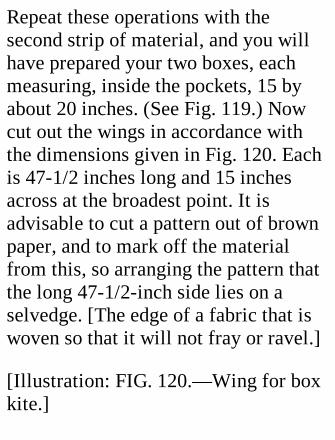
Repeat these operations with thesecond strip of material, and you willhave prepared your two boxes, eachmeasuring, inside the pockets, 15 byabout 20 inches. (See Fig. 119.) Nowcut out the wings in accordance withthe dimensions given in Fig. 120. Eachis 47-1/2 inches long and 15 inchesacross at the broadest point. It isadvisable to cut a pattern out of brownpaper, and to mark off the materialfrom this, so arranging the pattern thatthe long 47-1/2-inch side lies on aselvedge. [The edge of a fabric that iswoven so that it will not fray or ravel.]
[Illustration: FIG. 120.—Wing for boxkite.]
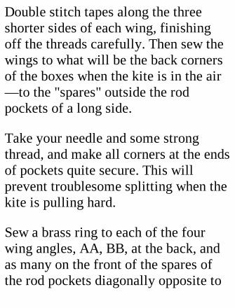
Double stitch tapes along the threeshorter sides of each wing, finishingoff the threads carefully. Then sew thewings to what will be the back cornersof the boxes when the kite is in the air—to the "spares" outside the rodpockets of a long side.
Take your needle and some strongthread, and make all corners at the endsof pockets quite secure. This willprevent troublesome splitting when thekite is pulling hard.
Sew a brass ring to each of the fourwing angles, AA, BB, at the back, andas many on the front of the spares ofthe rod pockets diagonally opposite to
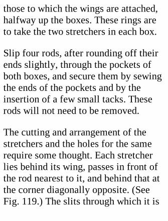
those to which the wings are attached,halfway up the boxes. These rings areto take the two stretchers in each box.
Slip four rods, after rounding off theirends slightly, through the pockets ofboth boxes, and secure them by sewingthe ends of the pockets and by theinsertion of a few small tacks. Theserods will not need to be removed.
The cutting and arrangement of thestretchers and the holes for the samerequire some thought. Each stretcherlies behind its wing, passes in front ofthe rod nearest to it, and behind that atthe corner diagonally opposite. (SeeFig. 119.) The slits through which it is
thrust should be strengthened withpatches to prevent ripping of thematerial.
Two persons should hold a box out assquarely as possible while a stretcher ismeasured. Cut a nick 3/8 inch deep inone end of the stretcher, and pass theend through the fabric slits to the ringnot on the wing. Pull the wing out,holding it by its ring, and cut thestretcher off 1 inch from the nearestpoint of the ring. The extra length willallow for the second nick and thetensioning of the material. Nowmeasure off the second stretcher by thefirst, nick it, and place it in position. Ifthe tension seems excessive, shorten
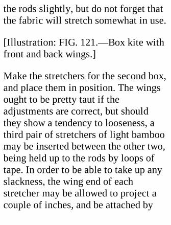
the rods slightly, but do not forget thatthe fabric will stretch somewhat in use.
[Illustration: FIG. 121.—Box kite withfront and back wings.]
Make the stretchers for the second box,and place them in position. The wingsought to be pretty taut if theadjustments are correct, but shouldthey show a tendency to looseness, athird pair of stretchers of light bamboomay be inserted between the other two,being held up to the rods by loops oftape. In order to be able to take up anyslackness, the wing end of eachstretcher may be allowed to project acouple of inches, and be attached by
string to the near ring, as described onp. 271. The bridle to which the flyingstring is attached is made up of fourparts, two long, two short, pairedexactly as regards length. These areattached to eyes screwed into the frontrods three inches below the tops of theboxes. Adjustment is made very easy ifa small slider is used at the kite end ofeach part. These sliders should be ofbone or some tough wood, and measure1 inch by 3/8 inch. The forward ends ofthe bridle are attached to a brass ringfrom which runs the flying string.
It is advisable to bind the stretcherswith strong thread just behind thenotches to prevent splitting, and to
loosen the stretchers when the kite isnot in use, to allow the fabric to retainas much as possible of its elasticity.
The area of the kite affected by wind isabout 14 square feet; the total weight,1-1/2 lb. The cost of material is about2s.
The experience gained from makingthe kite described may be used in theconstruction of a larger kite, six ormore feet high, with boxes 30 by 22 by22 inches, and wings 24 inches wide atthe broadest point. If a big lift isrequired, or it is desired to have a kiteusable in very light breezes, a secondpair of wings slightly narrower than
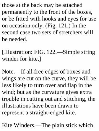
those at the back may be attachedpermanently to the front of the boxes,or be fitted with hooks and eyes for useon occasion only. (Fig. 121.) In thesecond case two sets of stretchers willbe needed.
[Illustration: FIG. 122.—Simple stringwinder for kite.]
Note.—If all free edges of boxes andwings are cut on the curve, they will beless likely to turn over and flap in thewind; but as the curvature gives extratrouble in cutting out and stitching, theillustrations have been drawn torepresent a straight-edged kite.
Kite Winders.—The plain stick which
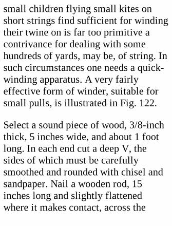
small children flying small kites onshort strings find sufficient for windingtheir twine on is far too primitive acontrivance for dealing with somehundreds of yards, may be, of string. Insuch circumstances one needs a quick-winding apparatus. A very fairlyeffective form of winder, suitable forsmall pulls, is illustrated in Fig. 122.
Select a sound piece of wood, 3/8-inchthick, 5 inches wide, and about 1 footlong. In each end cut a deep V, thesides of which must be carefullysmoothed and rounded with chisel andsandpaper. Nail a wooden rod, 15inches long and slightly flattenedwhere it makes contact, across the
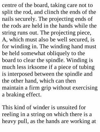
centre of the board, taking care not tosplit the rod, and clinch the ends of thenails securely. The projecting ends ofthe rods are held in the hands while thestring runs out. The projecting piece,A, which must also be well secured, isfor winding in. The winding hand mustbe held somewhat obliquely to theboard to clear the spindle. Winding ismuch less irksome if a piece of tubingis interposed between the spindle andthe other hand, which can thenmaintain a firm grip without exercisinga braking effect.
This kind of winder is unsuited forreeling in a string on which there is aheavy pull, as the hands are working at
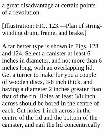
a great disadvantage at certain pointsof a revolution.
[Illustration: FIG. 123.—Plan of string-winding drum, frame, and brake.]
A far better type is shown in Figs. 123and 124. Select a canister at least 6inches in diameter, and not more than 6inches long, with an overlapping lid.Get a turner to make for you a coupleof wooden discs, 3/8 inch thick, andhaving a diameter 2 inches greater thanthat of the tin. Holes at least 3/8 inchacross should be bored in the centre ofeach. Cut holes 1 inch across in thecentre of the lid and the bottom of thecanister, and nail the lid concentrically

to one disc, the canister itself to theother. Then push the lid on the tin andsolder them together. This gives you alarge reel. For the spindle you willrequire a piece of brass tubing or steelbar 1 foot long and large enough tomake a hard driving fit with the holesin the wood. Before driving it in, makea framework of 3/4-inch strip iron (Fig.123), 3/32 or 1/8 inch thick, for the reelto turn in. The width of this frameworkis 1 inch greater than the length of thereel; its length is twice the diameter ofthe canister. Rivet or solder the endstogether. Halfway along the sides boreholes to fit the spindle.
Make a mark 1 inch from one end of
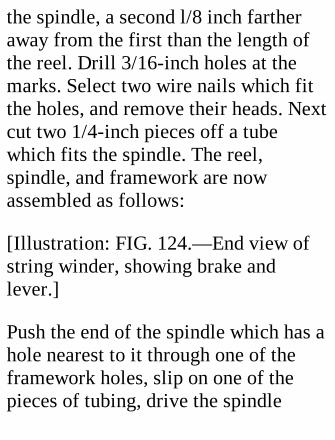
the spindle, a second l/8 inch fartheraway from the first than the length ofthe reel. Drill 3/16-inch holes at themarks. Select two wire nails which fitthe holes, and remove their heads. Nextcut two 1/4-inch pieces off a tubewhich fits the spindle. The reel,spindle, and framework are nowassembled as follows:
[Illustration: FIG. 124.—End view ofstring winder, showing brake andlever.]
Push the end of the spindle which has ahole nearest to it through one of theframework holes, slip on one of thepieces of tubing, drive the spindle
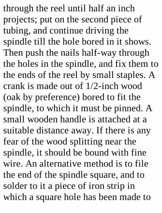
through the reel until half an inchprojects; put on the second piece oftubing, and continue driving thespindle till the hole bored in it shows.Then push the nails half-way throughthe holes in the spindle, and fix them tothe ends of the reel by small staples. Acrank is made out of 1/2-inch wood(oak by preference) bored to fit thespindle, to which it must be pinned. Asmall wooden handle is attached at asuitable distance away. If there is anyfear of the wood splitting near thespindle, it should be bound with finewire. An alternative method is to filethe end of the spindle square, and tosolder to it a piece of iron strip inwhich a square hole has been made to
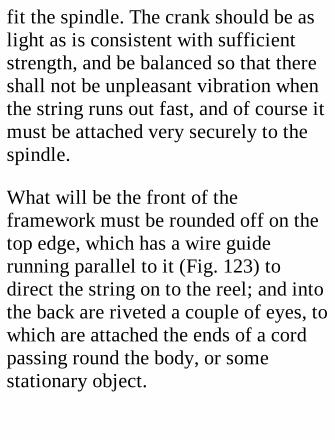
fit the spindle. The crank should be aslight as is consistent with sufficientstrength, and be balanced so that thereshall not be unpleasant vibration whenthe string runs out fast, and of course itmust be attached very securely to thespindle.
What will be the front of theframework must be rounded off on thetop edge, which has a wire guiderunning parallel to it (Fig. 123) todirect the string on to the reel; and intothe back are riveted a couple of eyes, towhich are attached the ends of a cordpassing round the body, or somestationary object.
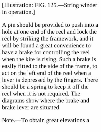
[Illustration: FIG. 125.—String winderin operation.]
A pin should be provided to push into ahole at one end of the reel and lock thereel by striking the framework, and itwill be found a great convenience tohave a brake for controlling the reelwhen the kite is rising. Such a brake iseasily fitted to the side of the frame, toact on the left end of the reel when alever is depressed by the fingers. Thereshould be a spring to keep it off thereel when it is not required. Thediagrams show where the brake andbrake lever are situated.
Note.—To obtain great elevations a
fine wire (piano wire 1/32 inch indiameter) is generally used, but toprotect the user against electric shocksthe wire must be connected with an"earthed" terminal, on the principle ofthe lightning conductor.
XXIV. PAPER GLIDERS.
In this chapter are brought to yournotice some patterns of paper gliderswhich, if made and handled carefully,prove very satisfactory. Gliders aresensitive and "moody" things, so thatfirst experiments may be attended by

failure; but a little persistence willbring its reward, and at the end of a fewhours you will, unless very unlucky, bethe possessor of a good specimen ortwo.
The three distinguishing features of agood glider are stability, straightnessof flight, and a small gliding angle. Ifthe last is as low as 1 in 10, so that themodel falls but 1 foot vertically whileprogressing 10 feet horizontally, theglider is one to be proud of.
Materials.—The materials needed forthe gliders to be described aremoderately stout paper—cream-laidnotepaper is somewhat heavy for the
purpose—and a little sealing wax orthin sheet metal for weighting.
[Illustration: FIG. 126.—Paper glider:Model "A."]
[Illustration: FIG. 127.—How tolaunch Model "A."]
Model "A."—Double a piece of paper 8inches long and 2-1/2 inches wide, andcut out, through both folds, the shapeshown in Fig. 126. Flatten the pieceand fold the "head" inwards four timeson the side away from the direction inwhich the paper was folded beforebeing cut out. Flatten the folds and fixto the centre a little clip formed bydoubling a piece of thin metal 3/16 by

1/2 inch. Make certain that the wingsare quite flat, and then, holding theglider between thumb and first finger,as shown in Fig. 127, push it off gently.If the balance is right, it will fly quite along way with an undulating motion. Iftoo heavy in front, it will dive; if toolight, it will rise suddenly and slipbackwards to the ground. The clip orthe amount of paper in the head mustbe modified accordingly. This type isextraordinarily efficient if thedimensions, weighting, and shape arecorrect, and one of the easiest possibleto make.
Model "B."—The next model (Fig.128), suggesting by its shape the

Langley steam-driven aeroplane, hastwo sets of wings tandem. Double apiece of paper and cut out of both foldssimultaneously a figure of the shapeindicated by the solid lines in thediagram. The portion A is square, andforms the head weight; B indicates thefront planes, C the rear planes. Bendthe upper fold of each pair into thepositions B1, C1, marked by dottedlines. Their front edges make less thana right angle with the keel, to ensurethe wings slanting slightly upwardstowards the front when expanded.
The model is now turned over, and theother wings are folded exactly on topof their respective fellows. Then the
halves of the head are folded twiceinwards, to bring the paper into ascompact a form as possible. It remainsto open out the wings at right angles tothe keel, and then raise their tipsslightly so that the two planes of a pairshall make what is called a "dihedral"angle with one another.
[Illustration: FIG. 128.—Details ofpaper gliders: Model "B" above,Model "C" below.]
Before launching, look at your modelendways and make sure that the rearplanes are exactly in line with those infront. It is essential that they should beso for straight flight. Then grip the keel
at its centre between finger and thumband launch gently. Mark how yourglider behaves. If it plungespersistently, trim off a very little of thehead. If, on the contrary, it settlesalmost vertically, weight must beadded in front. The position of theweight is soon found by sliding a metalclip along the keel until a good result isobtained.
Note that if the leading edges of thefront wings are bent slightlydownwards the glider may fly muchbetter than before.
A good specimen of this type is sostable that if launched upside down it
will right itself immediately and makea normal flight.
Model "C."—This is cut out of doubledpaper according to the solid lines ofFig. 128. The three sets of planes arebent back in the manner alreadydescribed, but the front planes aregiven a somewhat steeper angle thanthe others. This type is very stable andvery fairly efficient.
General Remarks.—Always pick up aglider by the keel or middle, not by oneof the wings, as a very little distortionwill give trouble.
The merits of a glider depend onlength, and on straightness of flight; so
in competition the launching heightshould be limited by a string stretchedacross the room, say 6 feet above thefloor. If the room be too short for aglider to finish its flight, the elevationat which it strikes the wall is themeasure of its efficiency.
Out-of-door flights are impracticablewith these very frail models when thereis the slightest breeze blowing. On aperfectly calm day, however, muchbetter fun can be got out of doors thanin, owing to the greater space available.A good glider launched from a second-floor window facing a large lawnshould travel many yards beforecoming to grass.
Large gliders of the types detailedabove can be made of very stout paperstiffened with slips of cane or bamboo;but the time they demand inconstruction might perhaps be moreprofitably spent on a power-drivenaeroplane such as forms the subject ofthe next chapter.
XXV. A SELF-LAUNCHING MODELAEROPLANE.By V. E. Johnson, M.A.
This article deals not with a scalemodel—a small copy of some full-sized machine—but with one designedfor actual flight; with one not specially
intended to create records either oflength or duration, but which, althoughsmall details must perforce be omitted,does along its main lines approximateto the "real thing."
Partly for this reason, and partlybecause it proves a far more interestingmachine, we choose a model able torise from the ground under its ownpower and make a good flight afterrising, assuming the instructions whichwe give to have been carefully carriedout. It is perhaps hardly necessary toadd that such a machine can always belaunched by hand when desired.
Before entering into special details we
may note some broad principles whichmust be taken into account if success isto attend our efforts.
Important Points.—It is absolutelyessential that the weight be kept downas much as possible. It is quite amistake to suppose that weightnecessarily means strength. On thecontrary, it may actually be a cause ofweakness if employed in the wrongplace and in the wrong way. Theheavier the machine, the more seriousthe damage done in the event of a badlanding. One of the best and easiestways of ensuring lightness is to let themodel be of very simple construction.Such a model is easier to build and
more efficient when constructed thanone of more complicated design.Weigh every part of your model as youconstruct it, and do not be content untilall symmetrically arranged parts whichshould weigh the same not only lookalike but do actually balance oneanother. (Note.—The writer alwaysworks out the various parts of hismodels in grammes, not ounces.) If asufficiently strong propeller bearingweighing only half a gramme can beemployed, so much the better, as youhave more margin left for some otherpart of the model in which it would beinadvisable to cut down the weight to avery fine limit.
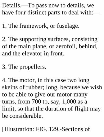
Details.—To pass now to details, wehave four distinct parts to deal with:—
1. The framework, or fuselage.
2. The supporting surfaces, consistingof the main plane, or aerofoil, behind,and the elevator in front.
3. The propellers.
4. The motor, in this case two longskeins of rubber; long, because we wishto be able to give our motor manyturns, from 700 to, say, 1,000 as alimit, so that the duration of flight maybe considerable.
[Illustration: FIG. 129.-Sections of
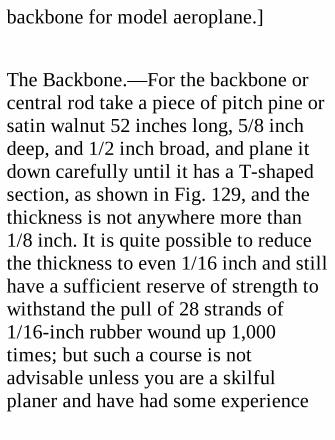
backbone for model aeroplane.]
The Backbone.—For the backbone orcentral rod take a piece of pitch pine orsatin walnut 52 inches long, 5/8 inchdeep, and 1/2 inch broad, and plane itdown carefully until it has a T-shapedsection, as shown in Fig. 129, and thethickness is not anywhere more than1/8 inch. It is quite possible to reducethe thickness to even 1/16 inch and stillhave a sufficient reserve of strength towithstand the pull of 28 strands of1/16-inch rubber wound up 1,000times; but such a course is notadvisable unless you are a skilfulplaner and have had some experience
in model-making.
If you find the construction of the T-shaped rod too difficult, two coursesare open—
(l) To get a carpenter to do the job foryou, or
(2) To give the rod the triangularsection shown in Fig. 129, each side ofthe equilateral triangle being half aninch long.
[Illustration: FIG. 150—Side elevationof model aeroplane.]
The top of the T or the base of thetriangle, as the case may be, is useduppermost. This rod must be pierced inthree places for the vertical mastsemployed in the bracing of the rod,trussing the main plane, and adjustingthe elevator. These are spaced out in
Fig. 130, which shows a side elevationof the model. Their sectionaldimensions are 1/16 by 1/4 inch; theirrespective lengths are given in Fig.130. Round the front edges and sharpenthe rear.
In Fig. 130 is shown the correctattitude or standing pose necessary tomake the model rise quickly and sweepboldly up into the air withoutskimming the ground for some 10 to 20yards as so many models do. E is theelevator (7 by 3 inches); A the mainplane (5-1/2 by 29 inches); W thewheels; and RS the rear skid,terminating in a piece of hooked steelwire. The vertical bracing of these

masts is indicated. The best material touse for the purpose is Japanese silk gut,which is very light and strong. Tobrace, drill a small, neat hole in themast and rod where necessary, passthrough, and tie. Do the same with eachone.
To return to the central mast, whichmust also form the chassis. This isdouble and opened out beneath asshown in Fig. 131, yz being a piecesimilar to the sides, which completes,the triangle x y z and gives thenecessary rigidity. Attach this piece byfirst binding to its extremities twostrips of aluminium, or by preferencevery thin tinned iron, Tl and T2. Bend
to shape and bind to xy, xz as shown inFig. 131.
[Illustration: FIG. 131.—Frontelevation of chassis.]
[Illustration: FIG. l32.-Wheel formodel aeroplane chassis.]
[Illustration: FIG. 133.—Plan of modelaeroplane.]
The Wheels and Chassis.—WW are thetwo wheels on which the model runs.They are made of hollow brass curtainrings, 1 inch in diameter, such as canbe bought at four a penny. For spokes,solder two strips of thin tinned iron tothe rings, using as little solder as
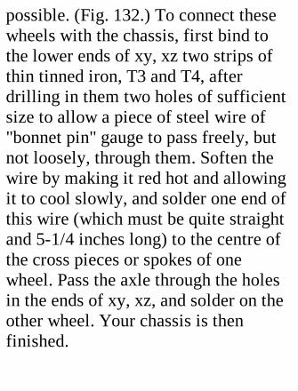
possible. (Fig. 132.) To connect thesewheels with the chassis, first bind tothe lower ends of xy, xz two strips ofthin tinned iron, T3 and T4, afterdrilling in them two holes of sufficientsize to allow a piece of steel wire of"bonnet pin" gauge to pass freely, butnot loosely, through them. Soften thewire by making it red hot and allowingit to cool slowly, and solder one end ofthis wire (which must be quite straightand 5-1/4 inches long) to the centre ofthe cross pieces or spokes of onewheel. Pass the axle through the holesin the ends of xy, xz, and solder on theother wheel. Your chassis is thenfinished.
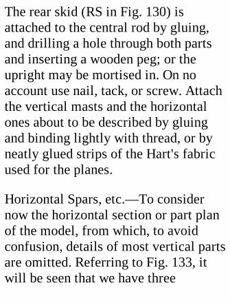
The rear skid (RS in Fig. 130) isattached to the central rod by gluing,and drilling a hole through both partsand inserting a wooden peg; or theupright may be mortised in. On noaccount use nail, tack, or screw. Attachthe vertical masts and the horizontalones about to be described by gluingand binding lightly with thread, or byneatly glued strips of the Hart's fabricused for the planes.
Horizontal Spars, etc.—To considernow the horizontal section or part planof the model, from which, to avoidconfusion, details of most vertical partsare omitted. Referring to Fig. 133, itwill be seen that we have three
horizontal masts or spars—HS1, 4inches; HS2, 6 inches; and HS3,slightly over 12 inches long. The last iswell steamed, slightly curved and leftto dry while confined in such a manneras to conform to the required shape. Itshould so remain at least twenty-fourhours before being fixed to the model.All the spars are attached by glue andneat cross bindings. If the central rodbe of triangular instead of T section,the join can be made more neatly. Thesame remarks apply to the two 9 and 10inch struts at the propeller end of therod, which have to withstand the pull ofthe rubber motor on PPl. These twopieces will have a maximum strengthand minimum weight if of the T
section used for the rod. If the work isdone carefully, 1/4 inch each way willbe sufficient.
Main Plane and Elevator.—Theframework of each plane is simply fourstrips of satin walnut or other suitablewood, 1/4 inch broad and 1/16 inch oreven less in thickness for the mainplane, and about 1/16 by 1/16 inch forthe elevator. These strips are first gluedtogether at the corners and left to set.The fabric (Hart's fabric or somesimilar very light material) is thenglued on fairly tight—that is, justsufficiently so to get rid of all creases.The main plane is then fixed flat on tothe top of the central rod by gluing and
cross binding at G and H. (A better butrather more difficult plan is to fastenthe rectangular frame on first and thenapply the fabric.) The same course isfollowed in dealing with the elevator,which is fixed, however, not to the rod,but to the 4-inch horizontal spar, HS1,just behind it, in such a manner as tohave a slight hinge movement at theback. This operation presents nodifficulty, and may be effected in avariety of ways. To set the elevator, useis made of the short vertical mast, M1.A small hole is pierced in the front sideof the elevator frame at Z, and throughthis a piece of thin, soft iron wire ispushed, bent round the spar, and tied.The other end of the wire is taken
forward and wrapped three or fourtimes round the mast M1, which shouldhave several notches in its front edge,to assist the setting of the elevator atdifferent angles. Pull the wire tight, sothat the elevator shall maintain aconstant angle when once set. H H1 is apiece of 25 to 30 gauge wire bent asshown and fastened by binding. Itpasses round the front of the rod, inwhich a little notch should be cut, so asto be able to resist the pull of the twinrubber motors, the two skeins of whichare stretched between H H1 and thehooks formed on the propeller spindles.If all these hooks are covered withcycle valve tubing the rubber will lastmuch longer. The rubber skeins pass

through two little light wire ringsfastened to the underside ends of HS2.(Fig. 133.)
The front skid or protector, FS, is madeout of a piece of thin, round, jointlesscane, some 9 inches in length, bentround as shown in Fig. 134, in which AB represents the front piece of the T-shaped rod and x y z a the cane skid;the portion x y passing on the near sideof the vertical part of the T, and z a onthe far side of the same. At E and Fthread is bound right round the rod.Should the nose of the machine strikethe ground, the loop of cane will bedriven along the underside of the rodand the shock be minimized. So adjust
matters that the skid slides fairly stiff.Note that the whole of the cane is onthe under side of the top bar of the T.
[Illustration: FIG. 134.—Front skid andattachment to backbone.]
Bearings.—We have still to deal withthe propellers and their bearings. Thelast, TN and TNl (Fig. 133), are simplytwo tiny pieces of tin about half agramme in weight, bent round thepropeller spar HS3 at B and B1. Take astrip of thin tin 1/4 inch wide and ofsufficient length to go completelyround the spar (which is 1/4 by 1/8inch) and overlap slightly. Solder theends together, using a minimum
amount of solder. Now bore two smallholes through wood and tin from rearto front, being careful to go through thecentre. The hole must be just largeenough to allow the propeller axle torun freely, but not loosely, in it.Primitive though such a bearing mayseem, it answers admirably in practice.The wood drills out or is soon wornmore than the iron, and the axle runsquite freely. The pull of the motor isthus directed through the thin curvedspar at a point where the resistance isgreatest—a very important matter inmodel aeroplane construction. Tostrengthen this spar further againsttorsional forces, run gut ties from Band Bl down to the bottom of the rear
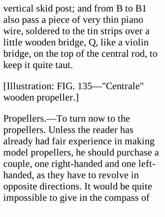
vertical skid post; and from B to B1also pass a piece of very thin pianowire, soldered to the tin strips over alittle wooden bridge, Q, like a violinbridge, on the top of the central rod, tokeep it quite taut.
[Illustration: FIG. 135—"Centrale"wooden propeller.]
Propellers.—To turn now to thepropellers. Unless the reader hasalready had fair experience in makingmodel propellers, he should purchase acouple, one right-handed and one left-handed, as they have to revolve inopposite directions. It would be quiteimpossible to give in the compass of

this article such directions as wouldenable a novice to make a reallyefficient propeller, and it must beefficient for even a decent flight with aself-launching model. The diameter ofthe two propellers should be about 11-1/2 to 11-3/4 inches, with a pitch angleat the extremities of about 25 to 30degrees as a limit. The "centrale" type(Fig. 135) is to be preferred. Suchpropellers can be procured at Messrs.A. W. Gamage, Ltd., Holborn, E.C.;Messrs. T. W. K. Clarke and Co.,Kingston-on-Thames; and elsewhere.
For the particular machine which weare considering, the total weight of thetwo propellers, including axle and hook
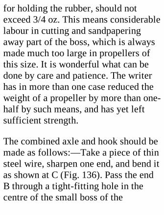
for holding the rubber, should notexceed 3/4 oz. This means considerablelabour in cutting and sandpaperingaway part of the boss, which is alwaysmade much too large in propellers ofthis size. It is wonderful what can bedone by care and patience. The writerhas in more than one case reduced theweight of a propeller by more than one-half by such means, and has yet leftsufficient strength.
The combined axle and hook should bemade as follows:—Take a piece of thinsteel wire, sharpen one end, and bend itas shown at C (Fig. 136). Pass the endB through a tight-fitting hole in thecentre of the small boss of the
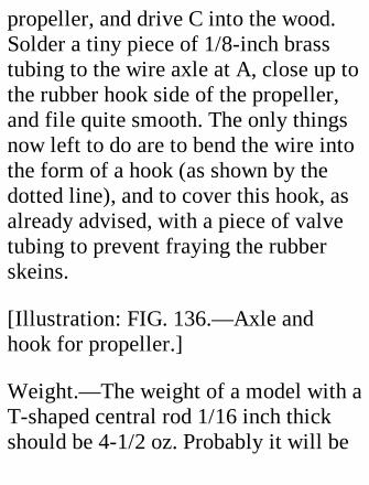
propeller, and drive C into the wood.Solder a tiny piece of 1/8-inch brasstubing to the wire axle at A, close up tothe rubber hook side of the propeller,and file quite smooth. The only thingsnow left to do are to bend the wire intothe form of a hook (as shown by thedotted line), and to cover this hook, asalready advised, with a piece of valvetubing to prevent fraying the rubberskeins.
[Illustration: FIG. 136.—Axle andhook for propeller.]
Weight.—The weight of a model with aT-shaped central rod 1/16 inch thickshould be 4-1/2 oz. Probably it will be
more than this—as a maximum let usfix 6 oz.—although 4-1/2 oz. is quitepossible, as the writer has proved inactual practice. In any case the centreof gravity of the machine without therubber motor should be situated 1 inchbehind the front or entering edge of themain plane. When the rubber motor (14strands of 1/16-inch rubber for eachpropeller, total weight 2 oz.) is inposition, the centre of gravity will befurther forward, in front of the mainplane. The amount of rubber mentionedis for a total weight of 6-1/2 oz. If theweight of the model alone be 6 oz., youwill probably have to use 16 strands,which again adds to the weight, andmakes one travel in a vicious circle.
Therefore I lay emphasis on the advice,Keep down the weight.
The front edge of the elevator shouldbe set about 3/8 inch higher than theback, and the model be tried first as aglider, with the rubber and propellersin position. If it glides satisfactorily,wind up the motor, say 500 turns, andlaunch by hand. When a good flight hasbeen obtained, and the correct angle ofthe elevator has been determined, placethe model on a strip of linoleum, windup, and release the propellers. Themodel should rise in its own length andremain in the air (if wound up 900turns) at least three quarters of aminute. Choose a calm day if possible.
If a wind blows, let the model face thebreeze. Remember that the model flieshigh, and select a wide open space. Donot push the model forward; justrelease the propellers, held one in eachhand near the boss by the fingers andthumb. As a lubricant for the rubberuse pure glycerine. It is advisable toemploy a geared-up mechanicalwinder, since to make 1,800 turns withthe fingers is rather fatiguing and verytedious.
Simple as this model may seem indesign, one built by the writer onexactly the lines given has met themost famous flying models of the dayin open competition and proved

successful against them.
XXVI. APPARATUS FORSIMPLE SCIENTIFICEXPERIMENTS.
Colour Discs for the Gramophone.—The gramophone, by virtue of its tablerevolving at a controllable speed,comes in useful for a series of opticalexperiments made with coloured discsbearing designs of different kinds.
The material needed for these discs iscardboard, covered with white paper on
one side, or the Bristol board used byartists. The discs on which the designsare drawn should be made as large asthe gramophone table will takeconveniently, so as to be viewed by anumber of people at once. Toencourage readers who do not possess agramophone, it may be pointed out thata gramophone, is merely aconvenience, and not indispensable forturning the discs, which may berevolved on a sharpened pencil or anyother spindle with pointed ends.
The Vanishing Spirals (Fig. 137).—This design, if spun slowly in aclockwise direction, gives one theimpression that the lines all move in
towards the centre. If the disc is turnedin an anti-clockwise direction, the linesseem to move towards thecircumference and disappear. To getthe proper effect the gaze should befixed and not attempt to follow thelines round.
[Illustration: FIG. 137.]
[Illustration: FIG. 138.]
The Rolling Circles.—Figs. 138 and139 are variations of the same idea. InFig. 138 two large circles are describedcutting one another and enclosing asmaller circle concentric with the disc.When spun at a certain rate the largercircles will appear to run independently
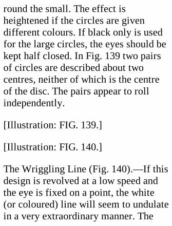
round the small. The effect isheightened if the circles are givendifferent colours. If black only is usedfor the large circles, the eyes should bekept half closed. In Fig. 139 two pairsof circles are described about twocentres, neither of which is the centreof the disc. The pairs appear to rollindependently.
[Illustration: FIG. 139.]
[Illustration: FIG. 140.]
The Wriggling Line (Fig. 140).—If thisdesign is revolved at a low speed andthe eye is fixed on a point, the white(or coloured) line will seem to undulatein a very extraordinary manner. The

line is made up of arcs of circles, andas the marking out is somewhat of ageometrical problem, a diagram (Fig.141) is added to show how it is done.The dotted curves are those parts of thecircles which do not enter into thedesign.
Begin by marking out the big circle Afor the disc. The circumference of thisis divided into six equal parts (chordequal to radius), and through the pointsof division are drawn the six lines fromthe centre. Describe circles aaa, eachhalf the diameter of A. The circles bbbare then drawn from centres on thelines RRR, and with the same radius asaaa., The same centres are used for
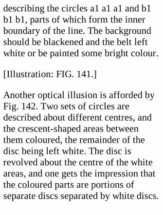
describing the circles a1 a1 a1 and b1b1 b1, parts of which form the innerboundary of the line. The backgroundshould be blackened and the belt leftwhite or be painted some bright colour.
[Illustration: FIG. 141.]
Another optical illusion is afforded byFig. 142. Two sets of circles aredescribed about different centres, andthe crescent-shaped areas betweenthem coloured, the remainder of thedisc being left white. The disc isrevolved about the centre of the whiteareas, and one gets the impression thatthe coloured parts are portions ofseparate discs separated by white discs.
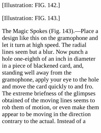
[Illustration: FIG. 142.]
[Illustration: FIG. 143.]
The Magic Spokes (Fig. 143).—Place adesign like this on the gramophone andlet it turn at high speed. The radiallines seem but a blur. Now punch ahole one-eighth of an inch in diameterin a piece of blackened card, and,standing well away from thegramophone, apply your eye to the holeand move the card quickly to and fro.The extreme briefness of the glimpsesobtained of the moving lines seems torob them of motion, or even make themappear to be moving in the directioncontrary to the actual. Instead of a
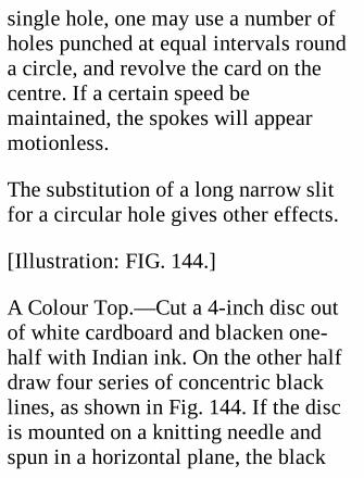
single hole, one may use a number ofholes punched at equal intervals rounda circle, and revolve the card on thecentre. If a certain speed bemaintained, the spokes will appearmotionless.
The substitution of a long narrow slitfor a circular hole gives other effects.
[Illustration: FIG. 144.]
A Colour Top.—Cut a 4-inch disc outof white cardboard and blacken one-half with Indian ink. On the other halfdraw four series of concentric blacklines, as shown in Fig. 144. If the discis mounted on a knitting needle andspun in a horizontal plane, the black
lines will appear of different colours. Aclockwise rotation makes theoutermost lines appear a greenish blue,those nearest the centre a dark red, andthe intermediate groups yellow andgreen. A reversal of the motionreverses the order of the colours, thered lines now being farthest from thecentre. The experiment is generallymost successful by artificial light,which contains a larger proportion ofred and yellow rays than does sunlight.The speed at which the top revolvesaffects the result considerably. Itshould be kept moderate, any excesstending to neutralize the colours.
[Illustration: FIG. 145.]
The Magic Windmill.—Mark a circle2-1/2 inches in diameter on a piece ofnotepaper, resting the centre leg [of thecompass] so lightly that it dentswithout piercing the paper. With thesame centre describe a 3/4-inch circle.Join the circles by eight equally spacedradial lines, and an eighth of an inchaway draw dotted parallel lines, all onthe same side of their fellow lines inorder of rotation. Cut out along thelarge circle, and then with a. sharpknife follow the lines shown double inFig. 145. This gives eight little vanes,each of which must be bent upwards toapproximately the same angle round aflat ruler held with an edge on thedotted line. Next make a dent with a
lead pencil at the exact centre on thevane side, and revolve the pencil untilthe dent is well polished.
[Illustration: FIG. 146.]
Hold a pin, point upwards, in the righthand, and with the left centre the mill,vanes pointing downwards, on the pin(Fig. 146). The mill will immediatelycommence to revolve at a steady pace,and will continue to do so indefinitely;though, if the head of the pin be stuckin, say, a piece of bread, no motion willoccur. The secret is that the heat of thehand causes a very slight upwardcurrent of warmed air, which issufficient to make the very delicately
poised windmill revolve.
A Pneumatic Puzzle.—For the verysimple apparatus illustrated by Fig. 147one needs only half a cotton reel, threepins, and a piece of glass or metaltubing which fits the hole in the reel.Adjust a halfpenny centrally over thehole and stick the pins into the reel atthree equidistant points, so that they donot quite touch the coin, and with theirends sloping slightly outwards to allowthe halfpenny to fall away.
[Illustration: FIG. 147.—Apparatus forillustrating an apparent scientificparadox.]
Press the coin against the reel and blow
hard through the tube. One wouldexpect the coin to fall; but, on thecontrary, the harder you blow thetighter will it stick, even if the reel bepointed downwards. Only when youstop blowing will it fall to the floor.
This is a very interesting experiment,and will mystify onlookers who do notunderstand the reason for the apparentparadox, which is this. The air blownthrough the reel strikes a very limitedpart of the nearer side of the halfpenny.In order to escape, it has to make aright-angle turn and pass between coinand reel, and, while travelling in thisdirection, loses most of its repulsiveforce. The result is that the total

pressure on the underside of the coin,plus the effect of gravity, is exactlybalanced by the atmospheric pressureon the outside, and the coin remains atthat distance from the reel which givesequilibrium of forces. When one stopsblowing, the air pressure on both sidesis the same, and gravity makes the coinfall away.
The function of the pins is merely tokeep the halfpenny centred on the hole.If steam is used instead of humanbreath, a considerable weight may behung from the disc without dislodgingit.
The Magic Swingers.—The easily
made toy illustrated next is much moreinteresting than would appear from themere picture, as it demonstrates a verystriking physical phenomenon, thetransference of energy. If twopendulums are hung close togetherfrom a flexible support and swung,their movements influence one anotherin a somewhat remarkable way—theswing of the one increasing as that ofthe other dies down, until a certainpoint is reached, after which theprocess is reversed, and the "dying" or"dead" pendulum commences to cometo life again at the expense of the other.This alternation is repeated over andover again, until all the energy of bothpendulums is exhausted.
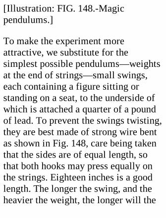
[Illustration: FIG. 148.-Magicpendulums.]
To make the experiment moreattractive, we substitute for thesimplest possible pendulums—weightsat the end of strings—small swings,each containing a figure sitting orstanding on a seat, to the underside ofwhich is attached a quarter of a poundof lead. To prevent the swings twisting,they are best made of strong wire bentas shown in Fig. 148, care being takenthat the sides are of equal length, sothat both hooks may press equally onthe strings. Eighteen inches is a goodlength. The longer the swing, and theheavier the weight, the longer will the
experiment last.
The swings are hung, six inches apart,from a stout string stretched tightlybetween two well-weighted chairs orbetween two fixed points. The stringshould be at least 4 feet long.
With two equally long and equallyweighted pendulums, the threefollowing experiments may be carriedout:—
1. Let one, A, start from rest. Theother, B will gradually die, and Aswing to and fro more and moreviolently, till B at last comes to a deadstop. Then A will die and B in turn getup speed. The energy originally
imparted to B is thus transferredthrough the string from one pendulumto the other an indefinite number oftimes, with a slight loss at everyalternation, until it is finally exhaustedby friction.
2. Swing them in opposite directions,but start A from a higher point than B.They will each alternately lose andgain motion, but will never come torest, and will continue to swing inopposite directions—that is, while Aswings north or east B will be swingingsouth or west, and vice versa.
3. Start them both in the samedirection, but one from a higher point
than the other. There will be the sametransference of energy as in (2), butneither will come to rest betweenalternations, and they will alwaysswing in the same direction.
Unequal Lengths.—If for one of theoriginal pendulums we substitute one acouple of inches longer than the other,but of the same weight, the same set ofthree experiments will provide sixvariations among them, as in each caseeither the longer or the shorter may bestarted first or given the longer initialswing, as the case may be. The resultsare interesting throughout, and shouldbe noted.
Three or more Pendulums.—If thenumber of pendulums be increased tothree or more, the length of all beingthe same, a fresh field for observationis opened. With an increase of numbera decrease in the individual weightingis advisable, to prevent an unduesagging of the string.
In conclusion, we may remark that astrong chain stretched between twotrees and a suitable supply of rope willenable the reader and his friends tocarry out all the experiments on a life-size scale.
A Smoke-ring Apparatus.—Get a largetin of the self-opening kind and cut a
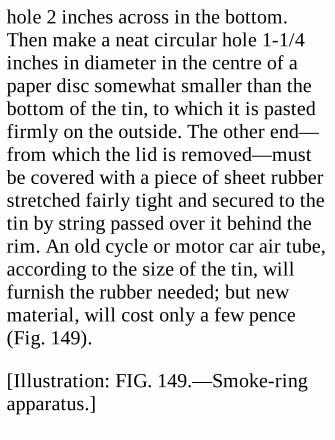
hole 2 inches across in the bottom.Then make a neat circular hole 1-1/4inches in diameter in the centre of apaper disc somewhat smaller than thebottom of the tin, to which it is pastedfirmly on the outside. The other end—from which the lid is removed—mustbe covered with a piece of sheet rubberstretched fairly tight and secured to thetin by string passed over it behind therim. An old cycle or motor car air tube,according to the size of the tin, willfurnish the rubber needed; but newmaterial, will cost only a few pence(Fig. 149).
[Illustration: FIG. 149.—Smoke-ringapparatus.]
A dense smoke is produced by puttingin the tin two small rolls of blottingpaper, one soaked in hydrochloric acid,the other in strong ammonia. The rollsshould not touch. To reduce corrosionof the tin by the acid, the inside shouldbe lined with thin card.
[Illustration: FIG. 150.—Smoke-making apparatus.]
A ring of smoke is projected from thehole in the card if the rubberdiaphragm is pushed inwards. A slow,steady push makes a fat, lazy ringcome out; a smart tap a thinner one,moving much faster. Absolutely stillair is needed for the best effects, as
draughts make the rings lose shapevery quickly and move erratically.Given good conditions, a lot of fun canbe got out of the rings by shooting onethrough another which has expandedsomewhat, or by destroying one bystriking it with another, or byextinguishing a candle set up at adistance, and so on. The experimentershould notice how a vortex ring rotatesin itself while moving forward, like arubber ring being rolled along a stick.
A continuous supply of smoke can beprovided by the apparatus shown inFig. 150. The bulb of a scent spray isneeded to force ammonia gas through abox, made air-tight by a rubber band

round the lid, in which is a pad soakedwith hydrochloric acid. The smokeformed in this box is expelled througha pipe into the ring-making box.
Caution.—When dealing withhydrochloric acid, take great care notto get it on your skin or clothes, as it isa very strong corrosive.
XXVII. A RAIN-GAUGE.
The systematic measurement ofrainfall is one of those pursuits whichprove more interesting in the doingthan in the prospect. It enables us to
compare one season or one year withanother; tells us what the weather hasbeen while we slept; affords a littlemild excitement when thunderstormsare about; and compensates to a limitedextent for the disadvantages of a wetday.
The general practice is to examine thegauge daily (say at 10 a.m.); tomeasure the water, if any, collectedduring the previous twenty-four hours;and to enter the record at once. Gaugesare made which record automaticallythe rainfall on a chart or dial, but theseare necessarily much more expensivethan those which merely catch thewater for measurement.
This last class, to which our attentionwill be confined chiefly, all includetwo principal parts—a metal receiverand a graduated glass measure, ofmuch smaller diameter than thereceiver, so that the divisionsrepresenting hundredths of an inch maybe far enough apart to bedistinguishable. It is evident that thesmaller the area of the measure is,relatively to that of the receiver, themore widely spaced will the graduationmarks of the measure be, and the moreexact the readings obtained.
[Illustration: FIG. 151.—Standard rain-gauge.]
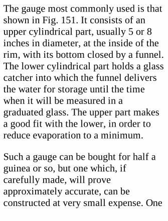
The gauge most commonly used is thatshown in Fig. 151. It consists of anupper cylindrical part, usually 5 or 8inches in diameter, at the inside of therim, with its bottom closed by a funnel.The lower cylindrical part holds a glasscatcher into which the funnel deliversthe water for storage until the timewhen it will be measured in agraduated glass. The upper part makesa good fit with the lower, in order toreduce evaporation to a minimum.
Such a gauge can be bought for half aguinea or so, but one which, ifcarefully made, will proveapproximately accurate, can beconstructed at very small expense. One
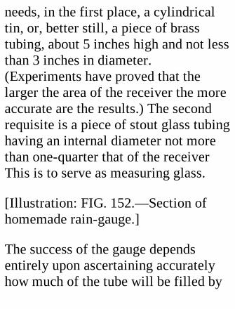
needs, in the first place, a cylindricaltin, or, better still, a piece of brasstubing, about 5 inches high and not lessthan 3 inches in diameter.(Experiments have proved that thelarger the area of the receiver the moreaccurate are the results.) The secondrequisite is a piece of stout glass tubinghaving an internal diameter not morethan one-quarter that of the receiverThis is to serve as measuring glass.
[Illustration: FIG. 152.—Section ofhomemade rain-gauge.]
The success of the gauge dependsentirely upon ascertaining accuratelyhow much of the tube will be filled by
a column of water 1 inch deep andhaving the same area as the receiver.This is easily determined as follows:—If a tin is to be used as receiver, makethe bottom and side joints watertightwith solder; if a tube, square off oneend and solder a flat metal to ittemporarily. The receptacle is placedon a perfectly level base, and water ispoured in until it reaches exactly to amark made 4 inches from the end of afine wire held perpendicularly. Nowcork one end of the tube and pour in thewater, being careful not to spill any,emptying and filling again if necessary.This will give you the number of tubeinches filled by the 4 inches in thereceiver. Divide the result by 4, and
you will have the depth unit in themeasure representing 1 inch of rainfall.The measuring should be done severaltimes over, and the average result takenas the standard. If the readings allagree, so much the better.
Preparing the Scale.—The next thing isto graduate a scale, which will mostconveniently be established in indeliblepencil on a carefully smoothed strip ofwhite wood 1 inch wide. First make azero mark squarely across the stripnear the bottom, and at the unitdistance above it a similar mark, overwhich "One Inch" should be writtenplainly. The distance between themarks is next divided by 1/2-inch lines
into tenths, and these tenths by 1/4-inch lines into hundredths, which, if thediameter of the receiver is four timesthat of the tube, will be about 3/16 inchapart. For reading, the scale is heldagainst the tube, with the zero marklevel with the top of the cork pluggingthe bottom. It will, save time andtrouble if both tube and scale areattached permanently to a board, whichwill also serve to protect the tubeagainst damage.
Making the Receiver.—A tin funnel,fitting the inside of the receiverclosely, should be obtained, or, if theexact article is not available, a longerone should be cut down to fit. Make a
central hole in the bottom of thereceiver large enough to allow thefunnel to pass through up to the swell,and solder the rim of the funnel to theinside of the receiver, using as littleheat as possible.
If you select a tin of the self-openingkind, you must now cut away the topwith a file or hack-saw, being verycareful not to bend the metal, asdistortion, by altering the area of theupper end of the tin, will render thegauge inaccurate.
The receiver should be supported byanother tin of somewhat smallerdiameter, and deep enough to contain a
bottle which will hold 3 or 4 inches ofrainfall. In order to prevent waterentering this compartment, tie a stripof rubber (cut out of an old cycle airtube) or other material round thereceiver, and projecting half an inchbeyond the bottom (Fig. 152).
All tinned iron surfaces should begiven a couple of thin coats or paint.
The standard distance between the raingauge and the ground is one foot. Theamount caught decreases with increaseof elevation, owing to the greater effectof the wind. The top of the gauge mustbe perfectly level, so that it may offerthe same catchment area to rain from
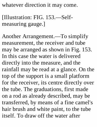
whatever direction it may come.
[Illustration: FIG. 153.—Self-measuring gauge.]
Another Arrangement.—To simplifymeasurement, the receiver and tubemay be arranged as shown in Fig. 153.In this case the water is delivereddirectly into the measure, and therainfall may be read at a glance. On thetop of the support is a small platformfor the receiver, its centre directly overthe tube. The graduations, first madeon a rod as already described, may betransferred, by means of a fine camel'shair brush and white paint, to the tubeitself. To draw off the water after
taking a reading, a hole should be burntwith a hot wire through the bottomcork. This hole is plugged with a pieceof slightly tapered brass rod, pushed intill its top is flush with the uppersurface of the cork.
If the tube has small capacity,provision should be made for catchingthe overflow by inserting through thecork a small tube reaching to aconvenient height-say the 1-inch mark.The bottom of the tube projects into aclosed storage vessel. Note that thetube must be in position before thegraduation is determined, otherwise thereadings will exaggerate the rainfall.
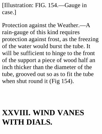
[Illustration: FIG. 154.—Gauge incase.]
Protection against the Weather.—Arain-gauge of this kind requiresprotection against frost, as the freezingof the water would burst the tube. Itwill be sufficient to hinge to the frontof the support a piece of wood half aninch thicker than the diameter of thetube, grooved out so as to fit the tubewhen shut round it (Fig 154).
XXVIII. WIND VANESWITH DIALS.
It is difficult to tell from a distance inwhich direction the arrow of a windvane points when the arrow liesobliquely to the spectator, or pointsdirectly towards or away from him. Inthe case of a vane set up in someposition where it will be plainly visiblefrom the house, this difficulty isovercome by making the wind vaneoperate an arrow moving round avertical dial set square to the point ofobservation. Figs. 155 to 157 aresketches and diagrams of an apparatuswhich does the work verysatisfactorily. The vane is attached tothe upper end of a long rod, revolvingfreely in brackets attached to the sideof a pole. The bottom end of the rod is
pointed to engage with a nick in abearer, in which it moves with but littlefriction. Near the end is fixed ahorizontal bevel-wheel, engaging witha vertical bevel of equal size andnumber of teeth attached to a short rodrunning through a hole in the post to anarrow on the other side. Between arrowand post is room for a dial on which thepoints of the compass are marked.
The construction of the apparatus is sosimple as to call for little comment.The tail of the vane is made of twopieces of zinc, tapering from 8 incheswide at the rear to 4 inches at the rod,to which they are clipped by 4 screwsand nuts. A stay soldered between them
near the stern keeps the broader ends acouple of inches apart, giving to thevane a wedge shape which is moresensitive to the wind than a single flatplate. The pointer also is cut out ofsheet metal, and is attached to the tailby means of the screws alreadymentioned. It must, of course, bearranged to lie in a line bisecting theangle formed by the two parts of thetail.
[Illustration: FIG. 165—Wind vanewith dial.]
The rod should preferably be of brass,which does not corrode like iron. If theuppermost 18 inches or so are of 1/4-

inch diameter, and assigned a bracketsome distance below the one projectingfrom the top of the pole, the remainderof the rod need not exceed 1/8 to 5/32inch in diameter, as the twisting strainon it is small. Or the rod may be builtup of wooden rods, well painted,alternating with brass at the pointswhere the brackets are.
[Illustration: FIG. 156.—Elevation andplan of vane.]
The Bevel Gearing.—Two brass bevelwheels, about 1 inch in diameter, andpurchasable for a couple of shillings orless, should be obtained to transmit thevane movements to the dial arrow.

Grooved pulleys, and a belt would dothe work, but not so positively, and anyslipping would, of course, render thedial readings incorrect. The arrowspindle (of brass) turns in a brass tube,driven tightly into a hole of suitablesize bored through the centre of thepost (Fig. 157). It will be well to fix alittle metal screen over the bevel gearto protect it from the weather.
[Illustration: FIG. 157.—Details ofbevel gear and arrow.]
The Dial—This is made of tinned ironsheet or of 1/4-inch wood nailed to 1/2-inch battens. It is held up to the post by3-inch screws passing through front
and battens. At the points of contact,the pole is slightly flattened to give agood bearing; and, to prevent the dialbeing twisted off by the wind, strip ironor stout galvanized wire stays run fromone end of a batten to the other behindthe post, to which they are secured.
The post should be well painted, thetop protected by a zinc disc laid underthe top bracket, and the bottom, up to apoint 6 inches above the ground level,protected by charring or by a coat ofboiled tar, before the dial and thebrackets for the vane rod to turn in arefastened on. A white dial and blackarrow and letters will be mostsatisfactory against a dark background;
and vice versa for a light background.The letters are of relatively littleimportance, as the position of thearrow will be sufficient indication.
It gives little trouble to affix to the topof the pole 4 arms, each carrying theinitial of one of the cardinal points ofthe compass. The position of theserelatively to the direction in which thedial will face must be carefully thoughtout before setting the position in theground. In any case the help of acompass will be needed to decidewhich is the north.
Having set in the post and rammed theearth tightly round it, loosen the
bracket supporting the vane rod so thatthe vane bevel clears the dial bevel.Turn the vane to true north, set the dialarrow also to north, and raise the bevelso that it meshes, and make the brackettight.
Note.—In the vicinity of London truenorth is 15 degrees east of the magneticnorth.
The pole must be long enough to raisethe vane clear of any objects whichmight act as screens, and its length willtherefore depend on its position. As forthe height of the dial above the ground,this must be left to individualpreference or to circumstances. If
conditions allow, it should be nearenough to the ground to be examinedeasily with a lamp at night, as one ofthe chief advantages of the system isthat the reading is independent of thevisibility of the vane.
A Dial Indoors.—If some prominentpart of the house, such as a chimneystack, be used to support the pole—which in such a case can be quite short—it is an easy matter to connect thevane with a dial indoors, provided thatthe rod can be run down an outsidewall.
An Electrically Operated Dial.—Thanks to the electric current, it is
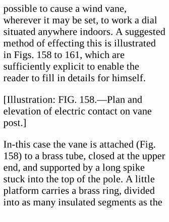
possible to cause a wind vane,wherever it may be set, to work a dialsituated anywhere indoors. A suggestedmethod of effecting this is illustratedin Figs. 158 to 161, which aresufficiently explicit to enable thereader to fill in details for himself.
[Illustration: FIG. 158.—Plan andelevation of electric contact on vanepost.]
In-this case the vane is attached (Fig.158) to a brass tube, closed at the upperend, and supported by a long spikestuck into the top of the pole. A littleplatform carries a brass ring, dividedinto as many insulated segments as the
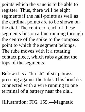
points which the vane is to be able toregister. Thus, there will be eightsegments if the half-points as well asthe cardinal points are to be shown onthe dial. The centre of each of thesesegments lies on a line running throughthe centre of the spike to the compasspoint to which the segment belongs.The tube moves with it a rotatingcontact piece, which rubs against thetops of the segments.
Below it is a "brush" of strip brasspressing against the tube. This brush isconnected with a wire running to oneterminal of a battery near the dial.
[Illustration: FIG. 159.—Magnetic

recording dial.]
The Dial.—This may be either verticalor horizontal, provided that the arrowis well balanced. The arrow, whichshould be of some light non-magneticmaterial, such as cardboard or wood,carries on its lower side, near the point,a piece of soft iron. Under the path ofthis piece is a ring of equally spacedmagnets, their number equaling that of,the segments on the vane. Betweenarrow and magnets is the dial on whichthe points are marked (Fig. 159).
Each segment is connected by aseparate wire with the correspondingdial magnet, and each of these, through

a common wire and switch, with theother terminal of the battery (Fig. 161).
In order to ascertain the quarter of thewind, the switch is closed. The magnetwhich is energized will attract theneedle to it, showing in what directionthe vane is pointing. To preventmisreading, the dial may be covered bya flap the raising of which closes thebattery circuit. A spring should bearranged to close the flap when thehand is removed, to prevent waste ofcurrent.
[Illustration: FIG. 160.—Another typeof electric dial with compass needle forpointer.]
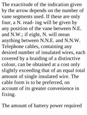
The exactitude of the indication givenby the arrow depends on the number ofvane segments used. If these are onlyfour, a N. read- ing will be given byany position of the vane between N.E.and N.W.; if eight, N. will meananything between N.N.E. and N.N.W.Telephone cables, containing anydesired number of insulated wires, eachcovered by a braiding of a distinctivecolour, can be obtained at a cost onlyslightly exceeding that of an equal totalamount of single insulated wire. Thecable form is to be preferred, onaccount of its greater convenience infixing.
The amount of battery power required

depends on the length of the circuit andthe delicacy of the dial. If an ordinarycompass needle be used, as indicated inFig. 160, very little current is needed.In this case the magnets, which can bemade of a couple of dozen turns of fineinsulated wire round a 1/8-in soft ironbar, should be arranged spokewiseround the compass case, and care mustbe taken that all the cores are wound inthe same direction, so as to have thesame polarity. Otherwise some willattract the N. end of the needle andothers repel it. The direction of thecurrent flow through the circuit willdecide the polarity of the magnets, sothat, if one end of the needle befurnished with a little paper arrow-

head, the "correspondence" betweenvane and dial is easily established. Anadvantage attaching to the use of acompass needle is that the magnetrepels the wrong end of the needle.
[Illustration: FIG. 161.—Generalarrangement of electric wind recorder.]
The brush and segments must beprotected from he weather by a cover,either attached to the segment platformor to the tube on which the vane ismounted.
The spaces between the segments mustbe filled in flush with some non-conducting material, such as fibre,vulcanite, or sealing-wax; and be very
slightly wider than the end of thecontact arm, so that two segments maynot be in circuit simultaneously. Incertain positions of the vane no contactwill be made, but, as the vane ismotionless only when there is no windor none to speak of, this is a smallmatter.
XXIX. A STRENGTH-TESTING MACHINE.
The penny-in-the-slot strength-testingmachine is popular among men andboys, presumably because many of
them like to show other people whattheir muscles are capable of, and theopportunity of proving it on agraduated dial is therefore tempting,especially if there be a possibility ofrecovering the penny by an unusuallygood performance.
For the expenditure of quite a smallnumber of pence, one may construct amachine which will show fairlyaccurately what is the value of one'sgrip and the twisting, power of thearms; and, even if inaccurate, willserve for competitive purposes. Theapparatus is very simple in principle,consisting of but five pieces of wood,an ordinary spring balance registering
up to 40 lbs., and a couple of handles.The total cost is but a couple ofshillings at the outside.
Fig. 162 is a plan of the machine asused for grip measuring. The base is apiece of deal 1 inch thick, 2 feet long,and 5-1/2 inches wide. The lever, L, ispivoted at P, attached to a springbalance at Q, and subjected to the pullof the hand at a point, R.
The pressure exerted at R is to thatregistered at Q as the distance PQ is tothe distance PR. As the spring balancewill not record beyond 40 lbs., the ratioof PQ to PR may conveniently be made5 to 1, as this will allow for the

performances of quite a strong man;but even if the ratio be lowered to 4 to1, few readers will stretch the balanceto its limit.
The balance should preferably be of thetype shown in Fig. 162, having anindicator projecting at right angles tothe scale through a slot, as this can bevery easily fitted with a sliding index,I, in the form of a 1/4-inch strip of tinbent over at the ends to embrace theedges of the balance.
CONSTRUCTION.
[Illustration: FIG. 162.—Plan of
strength tester.]
[Illustration: FIG. 163.—Grips ofstrength tester.]
As the pressures on the machine arehigh, the construction must be solidthroughout. The lever frame, A, andpivot piece, C, should be of one-inchoak, and the two last be screwed verysecurely to the baseboard. The shape ofA is shown in Fig. 163. The inside iscut out with a pad saw, a square notchbeing formed at the back for the leverto move in. The handles of an oldrubber chest expander come in usefulfor the grips. One grip, D, is used entirefor attachment to the lever; while of
the other only the wooden part isrequired, to be mounted on a 1/4-inchsteel bar running through the arms of Anear the ends of the horns. If a handleof this kind is not available for D, onemay substitute for it a piece of metaltubing of not less than 1/2-inchdiameter, or a 3/4-inch wooden rod,attached to an eye on the lever by awire passing through its centre.
A handle, if used, is joined to the leverby means of a brass plate 3/4 inch wideand a couple of inches long. A hole isbored in the centre somewhat smallerthan the knob to which the rubber wasfastened, and joined up to one longedge by a couple of saw cuts. Two
holes for good-sized screws must alsobe drilled and countersunk, and asocket for the knob must be scoopedout of the lever. After making screwholes in the proper positions, pass theshank of the knob through the slot inthe plate, and screw the plate on thelever. This method holds the handlefirmly while allowing it to movefreely.
The lever tapers from 1-1/2 inches atthe pivot to 5/8 inch at the balance end.The hole for the pivot—5/16-inch steelbar—should be long enough to admit apiece of tubing fitting the bar, todiminish friction, and an importantpoint, be drilled near the handle edge

of the lever, so as to leave plenty ofwood to take the strain. The last remarkalso applies to the hole for the balancepin at Q.
The balance support, B, and the pivotpiece, C, are 2-1/2 and 2-7/16 incheshigh respectively. Run a hole verticallythrough C and the baseboard for thepivot, which should be 4-1/2 incheslong, so as to project 1 inch whendriven right home. Take some troubleover getting the holes in L and C quitesquare to the baseboard, as anyinaccuracy will make the lever twist asit moves. To prevent the pivot cuttinginto the wood, screw to the top of C abrass plate bored to fit the pivot
accurately. The strain will then beshared by the screws.
The horns of A should be long enoughto allow the outside of the fixed grip tobe 2-1/4 inches from the inside of thehandle.
The balance is secured first to the leverby a pin driven through the eye of thehook, and then to B by a 3-inch screwpassed through the ring. The balanceshould just not be in tension.
When the apparatus is so far complete,test it by means of a second balanceapplied to D. Set the scale-marker atzero, and pull on the D balance till, say,35 lbs. is attained. If the fixed balance

shows 7 lbs. on what is meant to be a 5to 1 ratio, the setting of R relatively toP and Q is correct. If, however, there isa serious discrepancy, it would beworth while making tests with a verystrong balance, and establishing acorrected gradation on a paper dialpasted to the face of E.
For twisting tests we need a specialhandle (see Fig. 164), which is slippedon to the pivot and transmits the twistto L through a pin pressing on the backof the lever. The stirrup is made out ofstrip iron, bent to shape and drillednear the ends for the grip spindle. Tothe bottom is screwed and soldered abrass or iron plate, into the underside
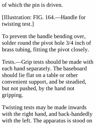
of which the pin is driven.
[Illustration: FIG. 164.—Handle fortwisting test.]
To prevent the handle bending over,solder round the pivot hole 3/4 inch ofbrass tubing, fitting the pivot closely.
Tests.—Grip tests should be made witheach hand separately. The baseboardshould lie flat on a table or otherconvenient support, and be steadied,but not pushed, by the hand notgripping.
Twisting tests may be made inwardswith the right hand, and back-handedlywith the left. The apparatus is stood on
edge, square to the performer, restingon the horns of A and a support nearthe balance.
Finger tests are made by placing thethumb on the front face of B, and twofingers on the farther side of the lever,one to the left and the other to the rightof the tail of the balance.
XXX. LUNG-TESTINGAPPARATUS.
The capacity of the lungs, and theirpowers of inspiration and expiration,

can be tested by means of easilyconstructed apparatus which willinterest most people who areintroduced to it. The reduction of thecapabilities of the lungs to figuresaffords a not unprofitable form ofentertainment, as even among adultsthese figures will be found to varywidely.
Air Volume Measuring.—The airwhich the lungs deal with isscientifically classified under fourheads:
1. Tidal air, which passes into and outof the lungs in natural breathing. About30 cubic inches in an adult (average).
2. Reserve air, which can be expelledafter a normal expiration. About 100cubic inches.
3. Complemental air, which can bedrawn in after a normal inspiration.About 100 cubic inches.
4. Residual air, which cannot beremoved from the lungs under anyconditions by voluntary effort. About120 cubic inches.
The first three added together give thevital capacity. This, as an addition sumwill show, is very much greater thanthe volume of air taken in during anormal inspiration.
The simplest method of testing thecapacity of an individual pair of lungsis embodied in the apparatus shown inFigs. 165 and 166. A metal box issubmerged, bottom upwards, in a tankof somewhat larger dimensions, untilthe water is level with the bottominside and out. A counterweight isattached to the smaller box to place italmost in equilibrium, so that if air isblown into the box it will at once beginto rise.
If we make the container 7-1/16 inchessquare inside, in plan, every inch itrises will represent approximately 50cubic inches of air blown in; and aheight of 7 inches, by allowing for 325
cubic inches, with a minimumimmersion of half an inch, shouldsuffice even for unusually capaciouslungs. The outside box need not bemore than 8 inches all ways.
[Illustration: FIG. 166.—Section oflung-capacity tester.]
Unless you are an expert with thesoldering iron, the making of the boxesshould be deputed to a professionaltinman, who would turn out the pair forquite a small charge. Specify very thinzinc for the air vessel, and have the topedges stiffened so that they mayremain straight.
On receiving the boxes, cut a hole 3/4-
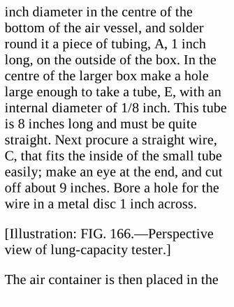
inch diameter in the centre of thebottom of the air vessel, and solderround it a piece of tubing, A, 1 inchlong, on the outside of the box. In thecentre of the larger box make a holelarge enough to take a tube, E, with aninternal diameter of 1/8 inch. This tubeis 8 inches long and must be quitestraight. Next procure a straight wire,C, that fits the inside of the small tubeeasily; make an eye at the end, and cutoff about 9 inches. Bore a hole for thewire in a metal disc 1 inch across.
[Illustration: FIG. 166.—Perspectiveview of lung-capacity tester.]
The air container is then placed in the
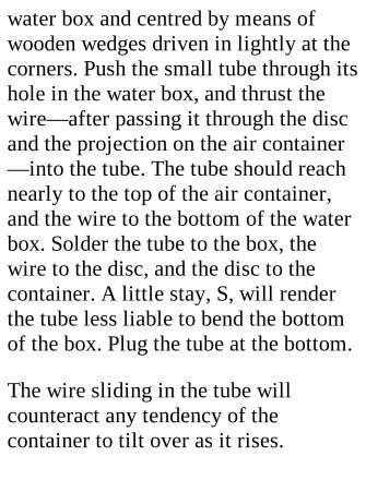
water box and centred by means ofwooden wedges driven in lightly at thecorners. Push the small tube through itshole in the water box, and thrust thewire—after passing it through the discand the projection on the air container—into the tube. The tube should reachnearly to the top of the air container,and the wire to the bottom of the waterbox. Solder the tube to the box, thewire to the disc, and the disc to thecontainer. A little stay, S, will renderthe tube less liable to bend the bottomof the box. Plug the tube at the bottom.
The wire sliding in the tube willcounteract any tendency of thecontainer to tilt over as it rises.
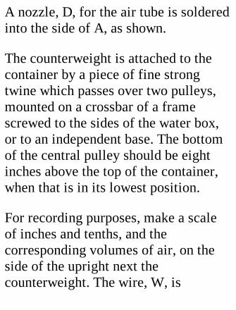
A nozzle, D, for the air tube is solderedinto the side of A, as shown.
The counterweight is attached to thecontainer by a piece of fine strongtwine which passes over two pulleys,mounted on a crossbar of a framescrewed to the sides of the water box,or to an independent base. The bottomof the central pulley should be eightinches above the top of the container,when that is in its lowest position.
For recording purposes, make a scaleof inches and tenths, and thecorresponding volumes of air, on theside of the upright next thecounterweight. The wire, W, is

arranged between counterweight andupright so that an easily sliding plate,P, may be pushed down it by theweight, to act as index.
[Illustration: FIG. 167.—Apparatus forshowing lung power.]
Notes.—The pulleys must work easily,to reduce friction, which renders thereadings inaccurate. Absolute accuracyis not obtainable by this apparatus, asthe rising of the container lowers thewater level slightly, and the air has tosupport part of the weight of thecontainer which was previously borneby the water. But the inaccuracy is sosmall as to be practically negligible.
A Pressure Recorder.
[Transcribers note: Even with theprecautions used in this project, healthstandards of 2004 would consider anyexposure to mercury dangerous. Watercould be substituted and the columnlengths scaled up by about 13.5.]
If mercury is poured into a verticaltube closed at the bottom, a pressure isexerted on the bottom in the proportionof approximately one pound per squareinch for every two inches depth ofmercury. Thus, if the column is 30inches high the bottom pressure isslightly under 15 lbs. per square inch.
This fact is utilized in the pressure
recorder shown in Fig. 167, a U-shapedglass tube half filled with mercury. Arubber tube is attached to the bent-overend of one of the legs, so that theeffects of blowing or suction may becommunicated to the mercury in thatleg. Normally the mercury stands levelin both tubes at what may be called thezero mark. Any change of level in oneleg is accompanied by an equal changein the opposite direction in the other.Therefore, if by blowing the mercury ismade to rise an inch in the left leg, thepressure exerted is obviously thatrequired to support a two-inch columnof mercury—that is, 1 lb. per sq. inch.This gives a very convenient standardof measurement, as every inch rise
above the zero mark indicates 1 lb. ofpressure.
CONSTRUCTION.
The mercury tube should be made first.Take a piece of glass tubing 20 incheslong, and bend it at a point 9 inchesfrom one end after heating in a spiritflame. The legs should be kept asparallel as possible. Lay the tube, whilethe heated part is still pliant, on a flatsurface, the bend projecting over theedge, So that the two legs shall be inline. When the glass has cooled, bendover two inches of the longer leg to anangle of about 45 degrees.

A standard for the tube is now madeout of one-inch wood. Hollow out a bedin which the tube shall lie and becompletely protected. To the right ofthe tube the standard is notched to takea small bottle. The notch should beslightly narrower than the diameter ofthe bottle, and have its sides hollowedout to fit.
Halfway up the tube draw a zero markacross the standards, and above this ascale of inches in fractions on bothsides. Each inch represents 1 lb.pressure.
The cork of the bottle must be piercedwith a red-hot wire for two glass tubes,
one of which is bent over for theblowing tube. Both tubes should bepointed at the bottle end so that theymay enter the cork easily. Make the topof the cork air tight with sealing-wax.The purpose of the bottle is to catchany mercury that might be sucked outof the tube; one does not wishmercurial poisoning to result from theexperiments. Also it prevents anysaliva entering the mercury tube.
When the latter has been secured to thestandard by a couple of slips of tinnailed to the front, connect it up withthe bottle, and fill it up to the zeromark with mercury poured in through asmall paper funnel.
The open end of the tube should beprovided with an inch of tubing. Clipsplaced on this and on the rubberconnection between tube and bottlewill prevent the escape of mercuryshould the apparatus be upset when notin use.
The average blowing pressure of whichthe lungs are capable is about 1-1/2 lbs.per square inch; inspiration pressurewithout mouth suction about 1 lb. persquare inch; suction pressure 2-1/2 to 3lbs. per square inch.
Caution.—Don't ask people with weaklungs to try experiments with theapparatus described in this chapter.
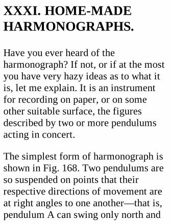
XXXI. HOME-MADEHARMONOGRAPHS.
Have you ever heard of theharmonograph? If not, or if at the mostyou have very hazy ideas as to what itis, let me explain. It is an instrumentfor recording on paper, or on someother suitable surface, the figuresdescribed by two or more pendulumsacting in concert.
The simplest form of harmonograph isshown in Fig. 168. Two pendulums areso suspended on points that theirrespective directions of movement areat right angles to one another—that is,pendulum A can swing only north and
south, as it were, and pendulum B onlyeast and west. On the top of B is aplatform to carry a card, and on theupper end of A a lever is pivoted so asto be able to swing only verticallyupwards and downwards. At its end thislever carries a pen, which when at restlies on the centre of the card platform.
[Illustration: FIG. 168.—SimpleRectilinear Harmonograph.]
The bob, or weight, of a pendulum canbe clamped at any point on its rod, sothat the rate or "period" of swing maybe adjusted or altered. The nearer theweight is brought to the point ofsuspension, the oftener will the

pendulum swing to and fro in a giventime—usually taken as one minute.From this it is obvious that the rates ofswing of the two pendulums can beadjusted relatively to one another. Ifthey are exactly equal, they are said tobe in unison, and under theseconditions the instrument would tracefigures varying in outline between theextremes of a straight line on the onehand and a circle on the other. Astraight line would result if bothpendulums were released at the sametime, a circle,[1] if one were releasedwhen the other had half finished aswing, and the intermediate ellipseswould be produced by variousalterations of "phase," or time of the
commencement of the swing of onependulum relatively to thecommencement of the swing of theother.
[Footnote 1: It should be pointed outhere that the presence of frictionreduces the "amplitude," or distancethrough which a pendulum moves, atevery swing; so that a true circlecannot be produced by free swingingpendulums, but only a spiral with coilsvery close together.]
But the interest of the harmonographcentres round the fact that the periodsof the pendulums can be tuned to oneanother. Thus, if A be set to swing

twice while B swings three times, anentirely new series of figures results;and the variety is further increased byaltering the respective amplitudes ofswing and phase of the pendulums.
We have now gone far enough to beable to point out why theharmonograph is so called. In the casejust mentioned the period rates of Aand B are as 2: 3. Now, if the note C onthe piano be struck the strings give acertain note, because they vibrate acertain number of times per second.Strike the G next above the C, and youget a note resulting from stringsvibrating half as many times again persecond as did the C strings—that is, the
relative rates of vibration of notes Cand G are the same as those ofpendulums A and B—namely, as 2 is to3. Hence the "harmony" of thependulums when so adjusted is knownas a "major fifth," the musical chordproduced by striking C and Gsimultaneously.
In like manner if A swings four timesto B's five times, you get a "majorthird;" if five times to B's six times, a"minor third;" and if once to B's threetimes, a "perfect twelfth;" if thrice toB's five times, a "major sixth;" if onceto B's twice, an "octave;" and so on.
So far we have considered the figures
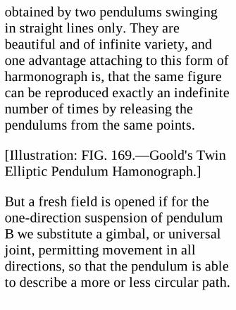
obtained by two pendulums swingingin straight lines only. They arebeautiful and of infinite variety, andone advantage attaching to this form ofharmonograph is, that the same figurecan be reproduced exactly an indefinitenumber of times by releasing thependulums from the same points.
[Illustration: FIG. 169.—Goold's TwinElliptic Pendulum Hamonograph.]
But a fresh field is opened if for theone-direction suspension of pendulumB we substitute a gimbal, or universaljoint, permitting movement in alldirections, so that the pendulum is ableto describe a more or less circular path.
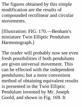
The figures obtained by this simplemodification are the results ofcompounded rectilinear and circularmovements.
[Illustration: FIG. 170.—Benham'sminiature Twin Elliptic PendulumHarmonograph.]
The reader will probably now see evenfresh possibilities if both pendulumsare given universal movement. Thiscan be effected with the independentpendulums; but a more convenientmethod of obtaining equivalent resultsis presented in the Twin EllipticPendulum invented by Mr. JosephGoold, and shown in Fig. 169. It

consists of—(1) a long pendulum, freeto swing in all directions, suspendedfrom the ceiling or some other suitablepoint. The card on which the figure isto be traced, and the weights, areplaced on a platform at the bottom ofthis pendulum. (2) A second andshorter free pendulum, known as the"deflector," hung from the bottom ofthe first.
This form of harmonograph givesfigures of infinite variety and ofextreme beauty and complexity. Itschief drawback is its length and weight,which render it more or less of afixture.
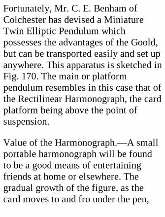
Fortunately, Mr. C. E. Benham ofColchester has devised a MiniatureTwin Elliptic Pendulum whichpossesses the advantages of the Goold,but can be transported easily and set upanywhere. This apparatus is sketched inFig. 170. The main or platformpendulum resembles in this case that ofthe Rectilinear Harmonograph, the cardplatform being above the point ofsuspension.
Value of the Harmonograph.—A smallportable harmonograph will be foundto be a good means of entertainingfriends at home or elsewhere. Thegradual growth of the figure, as thecard moves to and fro under the pen,
will arouse the interest of the leastscientifically inclined person; in fact,the trouble is rather to persuadespectators that they have had enoughthan to attract their attention. The cardson which designs have been drawn arein great request, so that the pleasure ofthe entertainment does not end with themere exhibition. An album filled withpicked designs, showing differentharmonies and executed in inks ofvarious colours, is a formidable rival tothe choicest results of the amateurphotographer's skill.
Practical Instructions for makingHarmonographs.
Pendulums.—For the Rectilinear typeof harmonograph wooden rods 5/8 to3/4 inch in diameter will be found verysuitable. They cost about 2d. each. Becareful to select straight specimens.The upper pendulum of the MiniatureTwin Elliptic type should be of stouterstuff, say a broomstick; that of theGoold apparatus stouter still.
All pendulums on which weights areslid up and down should be graduatedin inches and fractions, reckoning fromthe point of suspension as zero. Thegraduation makes it easy to re-establishany harmony after the weights havebeen shifted.
Suspensions.—For a harmonograph togive satisfaction it is necessary thatvery little friction should be set up atthe point of suspension, so that thependulums may lose amplitude ofswing very slowly.
One-way suspensions are easily made.Two types, the point and knife-edgerespectively, are shown in Fig. 168 andthe top part of Fig. 172. The pointsuspension is most suitable for smallrods and moderate weights; the knife-edge for large rods and heavy weightswhich would tend to crush a fine point.
[Illustration: FIG. 171.—Gimbalgiving universal movement: point
suspension.]
Points should rest in cup-shapeddepressions in a metal plate; knife-edges in V-shaped grooves in a metalring.
[Illustration: FIG. 172.—Knife-edgeuniversal-motion gimbal.]
Screws turned or filed to a sharp endmake convenient points, as they can bequickly adjusted so that a line joiningthe points lies exactly at right angles tothe pendulum. The cups to take thepoints should not be drilled until thepoints have been thus adjusted. Make apunch mark on the bedplate, and usingthis as centre for one of the points,
describe an arc of a circle with theother. This will give the exact centrefor the other cup. It is evident that ifpoints and cup centres do not coincideexactly there must be a certain amountof jamming and consequent friction.
In making a knife-edge, such as thatshown in Fig. 172, put the finishingtouches on with a flat file drawnlengthwise to ensure the edge beingrectilinear. For the same reason the Vslots in the ring support should beworked out together. If they are formedseparately, the chances are against theirbeing in line with one another.
Gimbals, or universal joints, giving
motion in all directions, require theemployment of a ring which supportsone pair of edges or points (Fig. 172),and is itself supported on another pairof edges or points set at right angles tothe first. The cups or nicks in the ringshould come halfway through, so thatall four points of suspension shall be inthe same plane. If they are not, thependulum will not have the sameswing-period in all directions. If agimbal does not work with equalfreedom in all ways, there will be atendency for the pendulum to losemotion in the direction in which mostfriction occurs.
By wedging up the ring of a gimbal the
motion of the pendulum is changedfrom universal to rectilinear. If you aremaking a harmonograph of the typeshown in Fig. 168, use a gimbal for theplatform pendulum, and design it sothat the upper suspension gives amotion at right angles to the penpendulum. The use of two little wedgeswill then convert the apparatus in amoment from semirectilinear to purelyrectilinear.
Weights.—The provision of weightswhich can be slipped up and down arod may present some difficulty. Ofiron and lead, lead is the moreconvenient material, as occupying lessspace, weight for weight, and being
more easily cast or shaped. I havefound thin sheet roofing lead, running 2lbs. to the square foot, very suitable formaking weights, by rolling a carefullysquared strip of the material round therod on which it will have to move, orround a piece of brass tubing which fitsthe rod. When the weight has beenrolled, drill four holes in it, on oppositesides near the ends, to take nails,shortened so that they just penetrate allthe laps but do not enter the centralcircular space. These will prevent thelaps sliding over one another endways.A few turns of wire round the weightover the heads makes everything snug.
Just one caution here. The outside lap
of lead should finish at the point on thecircumference where the first lapbegan, for the weight to beapproximately symmetrical about thecentre.
An alternative method is to melt upscrap lead and cast weights in tins orflowerpots sunk in sand, using anaccurately centred stick as the core.This stick should be very slightlylarger than the pendulum rod, to allowfor the charring away of the outside bythe molten metal. (Caution.—Themould must be quite dry.)
Failing lead, tin canisters filled withmetal scrap may be made to serve. It
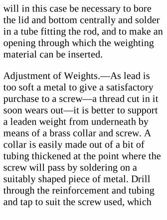
will in this case be necessary to borethe lid and bottom centrally and solderin a tube fitting the rod, and to make anopening through which the weightingmaterial can be inserted.
Adjustment of Weights.—As lead istoo soft a metal to give a satisfactorypurchase to a screw—a thread cut in itsoon wears out—it is better to supporta leaden weight from underneath bymeans of a brass collar and screw. Acollar is easily made out of a bit oftubing thickened at the point where thescrew will pass by soldering on asuitably shaped piece of metal. Drillthrough the reinforcement and tubingand tap to suit the screw used, which

may well be a camera tail screw, with alarge flat head.
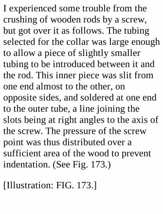
I experienced some trouble from thecrushing of wooden rods by a screw,but got over it as follows. The tubingselected for the collar was large enoughto allow a piece of slightly smallertubing to be introduced between it andthe rod. This inner piece was slit fromone end almost to the other, onopposite sides, and soldered at one endto the outer tube, a line joining theslots being at right angles to the axis ofthe screw. The pressure of the screwpoint was thus distributed over asufficient area of the wood to preventindentation. (See Fig. 173.)
[Illustration: FIG. 173.]
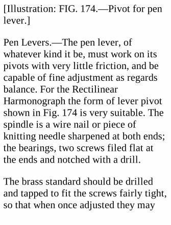
[Illustration: FIG. 174.—Pivot for penlever.]
Pen Levers.—The pen lever, ofwhatever kind it be, must work on itspivots with very little friction, and becapable of fine adjustment as regardsbalance. For the RectilinearHarmonograph the form of lever pivotshown in Fig. 174 is very suitable. Thespindle is a wire nail or piece ofknitting needle sharpened at both ends;the bearings, two screws filed flat atthe ends and notched with a drill.
The brass standard should be drilledand tapped to fit the screws fairly tight,so that when once adjusted they may
not slacken off. If the lever is made ofwood, the tail may be provided with anumber of metal pegs on which toplace the weights; if of wire, the tailshould be threaded so that a brassweight and lock screw may be movedalong it to any desired position. It isvery important that the pressure of thepen on the card should be reduced to aminimum by proper balancing, as thefriction generated by a "heavy" penslows the pendulum very quickly; andthat the centre of gravity should bebelow the point of suspension, to putthe pen in stable equilibrium. The levershown in Fig. 169 is suitable for theTwin Elliptic Pendulum.
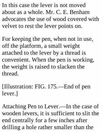
In this case the lever is not movedabout as a whole. Mr. C. E. Benhamadvocates the use of wood covered withvelvet to rest the lever points on.
For keeping the pen, when not in use,off the platform, a small weightattached to the lever by a thread isconvenient. When the pen is working,the weight is raised to slacken thethread.
[Illustration: FIG. 175.—End of penlever.]
Attaching Pen to Lever.—In the case ofwooden levers, it is sufficient to slit theend centrally for a few inches afterdrilling a hole rather smaller than the
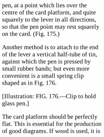
pen, at a point which lies over thecentre of the card platform, and quitesquarely to the lever in all directions,so that the pen point may rest squarelyon the card. (Fig. 175.)
Another method is to attach to the endof the lever a vertical half-tube of tin,against which the pen is pressed bysmall rubber bands; but even moreconvenient is a small spring clipshaped as in Fig. 176.
[Illustration: FIG. 176.—Clip to holdglass pen.]
The card platform should be perfectlyflat. This is essential for the productionof good diagrams. If wood is used, it is
advisable to glue two thin piecestogether under pressure, with the grainof one running at right angles to theother, to prevent warping.
Another important point is to have thecard platform square to the rod. If apiece of tubing fitting the rod is turnedup true in the lathe and soldered to adisc screwed to the underside of thetable, perpendicularity will be assured,and incidentally the table is rendereddetachable.
To hold the card in place on the table,slit a spring of an old photographicprinting frame down the middle, andscrew the two halves, convex side
upwards, by one end near two oppositecorners of the platform. (See Fig. 170.)If cards of the same size are alwaysused, the table should be marked toassist adjustment.
Making Pens.—The most satisfactoryform of pen is undoubtedly a piece ofglass tubing drawn out to a point,which is ground down quite smooth.The making of such pens is rather atedious business, but if care be taken ofthe pen when made it will last anindefinite time.
Tubing 3/16 or 1/8 inch in externaldiameter is suitable. Break it up (bynicking with a file) into 9-inch lengths.
Take a piece and hold its centre in theflame of a small spirit lamp, andrevolve it till it softens. Then draw theglass out in as straight a line aspossible, so that the points may becentral. If the drawing is done too fast,the points will be much too long to beof any use: half an inch of taper is quiteenough.
Assuming that a point of satisfactoryshape has been attained—and one mustexpect some failures before thishappens—the pen may be placed in thepen lever and ground down on aperfectly clean wet hone laid on thecard platform, which should be given acircular movement. Weight the lever so
as to put a fair pressure on the point.
The point should be examined fromtime to time under a strongmagnifying-glass, and tested byblowing through it into a glass ofwater. For very liquid ink the holeshould be as small as you can possiblyget it; thick inks, such as Indian,require coarser pens.
The sharp edge is taken off and thewidth of the point reduced by drawingthe pen at an angle along the stone,revolving it all the time. The nearer tothe hole you can wear the glass awaythe finer will be the line made by thepen.
Another method is as follows:—Sealthe point by holding it a moment in theflame. A tiny bulb forms on the end,and this has to be ground away till thecentral hole is reached. This isascertained by the water test, or byholding the pen point upwards, so thatlight is reflected from the tip, andexamining it under the magnifier. Thengrind the edge off, as in the first case.
Care of Pens.—The ink should be wellstrained, to remove the smallestparticles of "suspended matter," and bekept corked. Fill the pen by suction. Onno account allow the ink to dry in thepen. Squirt any ink out of it when it isdone with, and place it point

downwards in a vessel of water, whichshould have a soft rubber pad at thebottom, and be kept covered to excludedust. Or the pen may be cleaned outwith water and slipped into a holdermade by rolling up a piece ofcorrugated packing-paper. If the pointgets stopped up, stand the pen in nitricor sulphuric acid, which will probablydissolve the obstruction; andafterwards wash it out.
Inks.—I have found Stephens'scoloured inks very satisfactory, and canrecommend them.
Paper and Cards.—The paper or cardsused to draw the figures on should not
have a coated surface, as the coatingtends to clog the pen. The cheapestsuitable material is hot pressed paper, afew penny-worths of which will sufficefor many designs. Plain white cardswith a good surface can be bought forfrom 8s. to 10s. per thousand.
Lantern Slides.—Moisten one side of aclean lantern slide plate with paraffinand hold it over a candle flame till it isa dead black all over. Very finetracings can be obtained on the smokedsurface if a fine steel point issubstituted for the glass pen. Thedesign should be protected by a cover-glass attached to it by a binding stripround the edges.
Details of Harmonographs.
The reader may be interested in detailsof the apparatus shown in Figs. 168 and170, made by the writer.
The Rectilinear Harmonograph, shownin Fig. 168, has pendulums of 5/8-inchwood, 40 inches long, suspended 30inches from the lower ends, and set 10inches apart, centre to centre. Thesuspensions are of the point type. Theweights scale 5 lbs. each. The platformpendulum is provided with a secondweight, which can be affixed above thesuspension to slow that pendulum for2:3, 4:5, 7:8, and higher harmonies.
The baseboard is plain, and when the

apparatus is in action its ends aresupported on boxes or books laid ontwo tables, or on other convenientsupports. The whole apparatus can betaken to pieces very quickly fortransport. The total cost of materialsused did not exceed 3s. 6d.
The Twin Elliptic Pendulum of Fig.170 is supported on a tripod base madeof three pieces of 1-1/2 x 1-1/2 inchwood, 40 inches long, with ends cut offto an angle of 72 degrees to give aconvenient straddle, screwed at the topto an oak head 3/4 inch thick, andbraced a foot below the top byhorizontal crossbars 2 inches wide and1/2 inch thick. For transport this stand
can be replaced by a flat baseboardsimilar to that of the RectilinearHarmonograph described in the lastparagraph.
The main pendulum is a straight ashrod, 33 inches long and 1-1/4 inches indiameter, suspended 13-1/2 inchesfrom its upper end. Two weights of 4-1/2 lbs. each, made of rolled sheet lead,are provided for this pendulum.According to the nature of theharmony, one only, or both togetherbelow the suspension, or one above andone below, are used.
The weight of the lower pendulum, ordeflector, is supported on a disc,
resting on a pin passing through thebottom of a piece of brass tubing,which is provided with an eye at itsupper end. This eye is connected by ahook with several strands of silkthread, which are attached to the upperpendulum by part of a cycle tyre valve.The stem part of the valve was cut offfrom the nut, and driven into a suitablysized hole in the end of the mainpendulum. The screw collar for holdingthe valve in place had a little brass discsoldered to the outside, and this discwas bored centrally for the threads topass through. The edges of the hole hadbeen rounded off carefully to preventfraying of the threads. (Fig. 177.) Theover-all length of the pendulum,
reckoning from the point ofsuspension, is 20 inches. The weightsof the lower pendulum are several innumber, ranging from l lb. to 3 lbs.
[Illustration: FIG. 177.—Suspensionfor lower weight of Twin EllipticHarmonograph.]
Working the Harmonograph.—Apreliminary remark is needed here.Harmonies are, as we have seen, aquestion of ratio of swing periods. Thelarger the number of swings made bythe more quickly moving pendulumrelatively to that of the slowerpendulum in a given time, the higher orsharper is the harmony said to be.
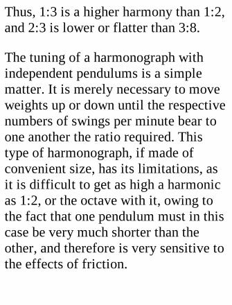
Thus, 1:3 is a higher harmony than 1:2,and 2:3 is lower or flatter than 3:8.
The tuning of a harmonograph withindependent pendulums is a simplematter. It is merely necessary to moveweights up or down until the respectivenumbers of swings per minute bear toone another the ratio required. Thistype of harmonograph, if made ofconvenient size, has its limitations, asit is difficult to get as high a harmonicas 1:2, or the octave with it, owing tothe fact that one pendulum must in thiscase be very much shorter than theother, and therefore is very sensitive tothe effects of friction.
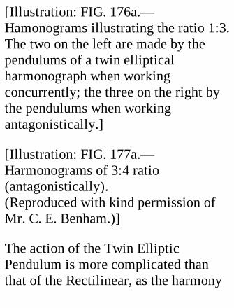
[Illustration: FIG. 176a.—Hamonograms illustrating the ratio 1:3.The two on the left are made by thependulums of a twin ellipticalharmonograph when workingconcurrently; the three on the right bythe pendulums when workingantagonistically.]
[Illustration: FIG. 177a.—Harmonograms of 3:4 ratio(antagonistically).(Reproduced with kind permission ofMr. C. E. Benham.)]
The action of the Twin EllipticPendulum is more complicated thanthat of the Rectilinear, as the harmony
ratio is not between the swings ofdeflector and upper pendulum, butrather between the swings of thedeflector and that of the system as awhole. Consequently "tuning" is amatter, not of timing, but ofexperiment.
Assuming that the length of thedeflector is kept constant—and inpractice this is found to be convenient—the ratios can be altered by alteringthe weights of one or both pendulumsand by adjustment of the upper weight.
For the upper harmonies, 1:4 down to3:8, the two pendulums may be almostequally weighted, the top one

somewhat more heavily than the other.The upper weight is brought down therod as the ratio is lowered.
To continue the harmonies beyond, say,2:5, it is necessary to load the upperpendulum more heavily, and to lightenthe lower one so that the proportionateweights are 5 or 6:1. Starting againwith the upper weight high on the rod,several more harmonies may beestablished, perhaps down to 4:7. Thena third alteration of the weights isneeded, the lower being reduced toabout one-twentieth of the upper, andthe upper weight is once moregradually brought down the rod.
Exact figures are not given, as muchdepends on the proportions of theapparatus, and the experimenter mustfind out for himself the exact positionof the main weight which gives anydesired harmonic. A few generalremarks on the action and working ofthe Twin Elliptic will, however, beuseful.
1. Every ratio has two forms.
(a) If the pendulums are workingagainst each other— antagonistically—there will be loops or points on theoutside of the figure equal in number tothe sum of the figures in the ratio.
(b) If the pendulums are working with
each other—concurrently—the loopsform inside the figure, and are equal innumber to the difference between thefigures of the ratio. To take the 1:3ratio as an example. If the tracing has3+1=4 loops on the outside, it is aspecimen of antagonistic rotation. If,on the other hand, there are 3-1=2loops on the inside, it is a case ofconcurrent rotation. (Fig. 176, A.)
2. Figures with a ratio of which thesum of the numbers composing it is aneven number (examples, 1:3, 3:5, 3:7)are symmetrical, one half of the figurereproducing the other. If the sum isUneven, as in 1:2, 2:3, 2:7, the figure isunsymmetrical. (Fig. 177, A.)

3. The ratio 1:3 is the easiest to beginupon, so the experimenter's first effortsmay be directed to it. He should watchthe growth of the figure closely, andnote whether the repeat line is made infront of or behind the previous line ofthe same loop. In the first case thefigure is too flat, and the weight of theupper pendulum must be raised; in thesecond case the weight must belowered. Immediately an exactharmonic is found, the position of theweight should be recorded.
Interesting effects are obtained byremoving the lower pendulum andallowing the apparatus to describe twoelliptical figures successively, one on

the top of the other, on the same card.The crossing of the lines gives a"watered silk" appearance to thedesign, which, if the pen is a very fineone and the lines very close together, isin many cases very beautiful.
Readers who wish for furtherinformation on this fascinating subjectare recommended to purchase"Harmonic Vibrations," published byMessrs. Newton and Co., 72 WigmoreStreet, London, W. This book, to whichI am much indebted, contains, besidesmuch practical instruction, a number ofcharming reproductions ofharmonograms.
Before closing this chapter I shouldlike to acknowledge the kind assistancegiven me by Mr. C. E. Benham, whohas made a long and careful study ofthe harmonograph.
XXXII. A SELF-SUPPLYING MATCHBOX.
This useful little article can beconstructed in a couple of hours by ahandy person. In general idea itconsists of a diamond-shaped box tohold vestas, working up and downdiagonally on a vertical member (A in
Fig. 179 (1)), which passes throughslits at the top and bottom, and runs ingrooves cut in the sides of the box. Thetop of A is grooved to allow a match torest on it. When the box is drawn up tothe full extent allowed by a transversepin in the slot shown in Fig. 179 (2),the groove is at the lowest point of thebox, and is covered by the matches.When the box is lowered, A catches avesta and takes it up through the top, asseen in Fig. 178, for removal by thefingers.
The only materials required are a cigar-box, some pins, and a supply of glue.The box should be carefully taken topieces, and the parts soaked in hot

water till freed of all paper, and thenallowed to dry under pressure, smallslips of wood being interposed acrossthe grain to keep them separate andpermit the passage of air.
[Illustration: FIG. 178.—Self-supplying matchbox, with match inposition for removal by fingers.]
When the wood is dry, cut out with afret saw two pieces shaped like Fig.179 (3), to form the ends of the box.Allow a little surplus, so that the edgesmay be finished off neatly with chiseland plane. The two ends should matchexactly, or there will be trouble at alater stage.

Now cut, down the centre of each agroove for one edge of A to run in. Bypreference it should be square; but ifyou do not possess the necessarychisel, a V groove made with a knifewill suffice—and, of course, in thiscase the edges of A will have to bebevelled to fit.
[Illustration: FIG. 179.—Details of selfsuplying matchbox.]
The four sides of the box, BB and CC,are next cut out. Their sectional shapeis shown in Fig. 179 (1). They shouldbe rather longer than the length of theordinary vesta, and all of exactly thesame length, and rectangular. A very
small hack saw (costing about 1s.) withfine teeth is the best possible tool forclose cutting, and a small 1 shillingiron plane is invaluable for truing andbevelling the edges.
The glue pot, which we will assume tobe ready for use, is now needed toattach the fixed B (the other B ishinged to form a lid for filling the boxthrough) and CC to the ends. Thisoperation must be carried outaccurately, so that the slots may not beblocked.
While the glue is setting, cut out A,allowing an extra 1/16 inch of widthfor fitting. The slot down the centre is
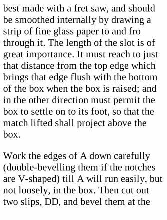
best made with a fret saw, and shouldbe smoothed internally by drawing astrip of fine glass paper to and frothrough it. The length of the slot is ofgreat importance. It must reach to justthat distance from the top edge whichbrings that edge flush with the bottomof the box when the box is raised; andin the other direction must permit thebox to settle on to its foot, so that thematch lifted shall project above thebox.
Work the edges of A down carefully(double-bevelling them if the notchesare V-shaped) till A will run easily, butnot loosely, in the box. Then cut outtwo slips, DD, and bevel them at the
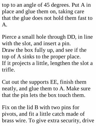
top to an angle of 45 degrees. Put A inplace and glue them on, taking carethat the glue does not hold them fast toA.
Pierce a small hole through DD, in linewith the slot, and insert a pin.Draw the box fully up, and see if thetop of A sinks to the proper place.If it projects a little, lengthen the slot atrifle.
Cut out the supports EE, finish themneatly, and glue them to A. Make surethat the pin lets the box touch them.
Fix on the lid B with two pins forpivots, and fit a little catch made ofbrass wire. To give extra security, drive
ordinary pins, cut off to 5/8 inch,through the sides into fixed B, CC, andDD, and through EE into A. This is aneasy enough business if pilot holes aremade with a very fine awl or a tinydrill, and a small, light hammer isused. It now remains only to go overthe whole box with glass paper oremery cloth, and to glue a diamond ofcoarse glass paper to one end forstriking the matches on.
Note that the lid must not be openedwhen the box is down, as it would bewrenched off its pivots.
XXXIII. A WOODENWORKBOX.
The box illustrated by Fig. 181 wascopied from an article of Norwegianmanufacture. Its construction is anextremely simple matter, provided thatone can get a piece of easily bent wood(birch, for instance), not exceeding3/16 inch in thickness, for the sides.
[Illustration: FIG. 180.—Showing howto draw an ellipse.]
[Illustration: FIG. 181.—Norwegianworkbox.]
The bottom of the box is made of 5/16
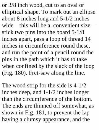
or 3/8 inch wood, cut to an oval orelliptical shape. To mark out an ellipseabout 8 inches long and 5-1/2 incheswide—this will be a. convenient size—stick two pins into the board 5-1/8inches apart, pass a loop of thread 14inches in circumference round these,and run the point of a pencil round thepins in the path which it has to takewhen confined by the slack of the loop(Fig. 180). Fret-saw along the line.
The wood strip for the side is 4-1/2inches deep, and 1-1/2 inches longerthan the circumference of the bottom.The ends are thinned off somewhat, asshown in Fig. 181, to prevent the laphaving a clumsy appearance, and the
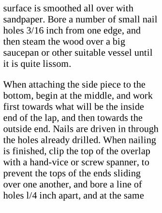
surface is smoothed all over withsandpaper. Bore a number of small nailholes 3/16 inch from one edge, andthen steam the wood over a bigsaucepan or other suitable vessel untilit is quite lissom.
When attaching the side piece to thebottom, begin at the middle, and workfirst towards what will be the insideend of the lap, and then towards theoutside end. Nails are driven in throughthe holes already drilled. When nailingis finished, clip the top of the overlapwith a hand-vice or screw spanner, toprevent the tops of the ends slidingover one another, and bore a line ofholes l/4 inch apart, and at the same
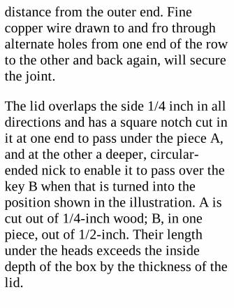
distance from the outer end. Finecopper wire drawn to and fro throughalternate holes from one end of the rowto the other and back again, will securethe joint.
The lid overlaps the side 1/4 inch in alldirections and has a square notch cut init at one end to pass under the piece A,and at the other a deeper, circular-ended nick to enable it to pass over thekey B when that is turned into theposition shown in the illustration. A iscut out of 1/4-inch wood; B, in onepiece, out of 1/2-inch. Their lengthunder the heads exceeds the insidedepth of the box by the thickness of thelid.
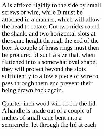
A is affixed rigidly to the side by smallscrews or wire, while B must beattached in a manner, which will allowthe head to rotate. Cut two nicks roundthe shank, and two horizontal slots atthe same height through the end of thebox. A couple of brass rings must thenbe procured of such a size that, whenflattened into a somewhat oval shape,they will project beyond the slotssufficiently to allow a piece of wire topass through them and prevent theirbeing drawn back again.
Quarter-inch wood will do for the lid.A handle is made out of a couple ofinches of small cane bent into asemicircle, let through the lid at each
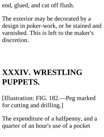
end, glued, and cut off flush.
The exterior may be decorated by adesign in poker-work, or be stained andvarnished. This is left to the maker'sdiscretion.
XXXIV. WRESTLINGPUPPETS.
[Illustration: FIG. 182.—Peg markedfor cutting and drilling.]
The expenditure of a halfpenny, and aquarter of an hour's use of a pocket
knife, bradawl, and pliers, will producea toy which is warranted to amusegrown-ups as well as children.Wrestlers made out of clothes pegsmay be bought for a copper or two inthe street, and are hardly a novelty; yeta few notes on home production willnot be a waste of space, as making ischeaper, and much more interesting,than buying.
The clothes pegs used must be of theshape shown in Fig. 182, with a roundtop. They cost one penny per dozen.
Drill holes through body and legs asindicated in Fig. 182. Cut the legs fromthe "trunk,'" and whittle them to the

shape of Fig. 183. The arms, made outof any thin wood, are 2-1/4 inches longbetween centres of end holes.
To get the best results the two arms andthe four legs should be paired off toexactly the same length.
[Illustration: FIG. 183.—Clothes-pegwrestlers.]
The neatest method of attaching theparts is to use small brass tacks, whichmust, of course, be of somewhat largerdiameter than the holes in the body.Holes in arms and legs are a loose fit,so that the wrestlers may be very loose-jointed, and the tacks must not bedriven in far enough to cause any
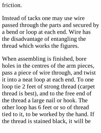
friction.
Instead of tacks one may use wirepassed through the parts and secured bya bend or loop at each end. Wire hasthe disadvantage of entangling thethread which works the figures.
When assembling is finished, boreholes in the centres of the arm pieces,pass a piece of wire through, and twistit into a neat loop at each end. To oneloop tie 2 feet of strong thread (carpetthread is best), and to the free end ofthe thread a large nail or hook. Theother loop has 6 feet or so of threadtied to it, to be worked by the hand. Ifthe thread is stained black, it will be
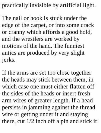
practically invisible by artificial light.
The nail or hook is stuck under theedge of the carpet, or into some crackor cranny which affords a good hold,and the wrestlers are worked bymotions of the hand. The funniestantics are produced by very slightjerks.
If the arms are set too close togetherthe heads may stick between them, inwhich case one must either flatten offthe sides of the heads or insert fresharm wires of greater length. If a headpersists in jamming against the threadwire or getting under it and stayingthere, cut 1/2 inch off a pin and stick it
into the front of the crown, so that thehead is arrested by the wire when thewrestler bends forward.
[Illustration: FIG. 184.—Largewrestlers made of stout wood.]
Large Wrestlers.—A more elaborateand realistic pair is shown in Fig. 184.The originals of the sketch are 8 incheshigh. Half-inch deal was used for thebodies, 3/8-inch for the legs and arms.The painting-in of hair, features, tights,and shoes adds considerably to theeffect. The heads and limbs are mereprofiles, but anyone with a turn forcarving might spend a little time inrounding off and adding details which
will make the puppets appear morelifelike.
XXXV. DOUBLEBELLOWS.
The small-sized bellows which havebecome popular in sitting-rooms areusually more ornamental than efficient,and make one think regretfully of theold-fashioned article of ample capacitywhich is seldom seen nowadays.
Fig. 185 illustrates a method ofcoupling up two small bellows in such
a manner as to provide an almostcontinuous blast, besides doubling theamount of air sent through the fire in agiven time, at the coat of but littleextra exertion. A piece of wood half aninch thick is screwed across onebellows just behind the valve hole. Thetwo bellows are then laid valve facingvalve, and are attached to one anotherby a strip of tin passed round the woodjust behind the nozzles and by tying thetwo fixed handles together.
[Illustration: FIG. 185.—Double-actingbellows. Two methods of couplingshown.]
Make a rectangle of stout wire

somewhat wider than the handles andlong enough to reach from the outerface of one moving handle to that ofthe other, when one bellows is quiteclosed and the other full open. Theends of the wire should be solderedtogether, and the ends of the link heldup to the handles by a couple ofstaples.
An alternative method is to use a pieceof wood with a screw driven into it atright angles near each end through thestaples on the handles (Fig. 185, a). Inplace of the staples you may use screw-in eyes fitting the screws.
XXXVI. A HOME-MADEPANTOGRAPH.
The pantograph is a simple apparatusfor copying drawings, maps, designs,etc., on a reduced or enlarged scale, orto the same size as the original.
[Illustration: FIG. 186.—Details ofsimple pantograph.]
A sketch of a pantograph is given inFig. 186. Four rods are jointed togetherto form a parallelogram, the sides ofwhich can be lengthened or shortenedto suit the scale of reproduction. One isattached by a fixed pivot at a to theboard on which the drawing is done. At

b and e are removable pivots, used foradjusting the rods; at c is a pivot whichprojects an inch or so below the rods.The pointer is inserted at d forenlargement, or at f for reduction, thepencil being in the unoccupied hole atd or f.
If a same-sized copy is desired, thefixed pivot is transferred to d, and thepencil and pointer placed at a and frespectively.
Construction of an Enlarging andReducing Pantograph.—Cut out of 1/8-inch oak, walnut, or beech four rods 5/8inch wide and 19 inches long. Smooththem well all over, and make marks
near the ends of each, exactly 18 inchesapart. The graduation of the rods forthe adjustment pivot holes is carriedout in accordance with themeasurements given in Fig. 187. It isadvisable to mark out and bore eachrod separately if you do not possess amachine which will drill holes quiteperpendicularly; if you do, all four rodscan be drilled at one operation.
In Fig. 187 the lower row of numeralsindicates the number of times (indiameters) the original is enlargedwhen all four holes similarly figuredare used; the upper row, the size of thecopy as compared with the original incase of reduction.
If proportions other than those givenare required, a very little calculationwill locate the necessary holes.
Pivots.—All the pivots must fit theirholes accurately, as any looseness atthe joints detracts from the truth ofreproduction. For pivots band b and emay use brass screws and small piecesof hard wood as nuts to hold them inposition. The nuts should screw onrather stiffly, and not be forced hardagainst the rods, as free motion withlittle friction at all joints is essentialfor good work.
[Illustration: FIG. 187.—Diagramshowing how to mark off pantograph
rods. The dotted lines above rod givedistances of holes from ends.]
The fixed pivot at a may be merely theshank of a wire nail of the proper sizedriven into the board, a cork collarbeing slipped over it to keep the rod theproper distance from the board. For cuse a screw to the head of which hasbeen soldered half an inch of a round-headed brass nail, which will moveeasily over the paper. At d is needed ahollow pivot, fashioned out of a quarterof an inch of pencil-point protector orsome other thin tube, burred overslightly at the ends so as not to fall out.The end of B at f has a slotted hole togrip the pencil or pointer, as the case
may be.
A Same-size Pantograph.—For makinga same-size copy, tracing may bepreferred to the use of a pantograph;but if a pantograph is adopted, a specialapparatus may be constructed for thepurpose. The arrangement is exactlythe same as that already described,excepting that the only holes neededare those at a, c, d, f, at the middlepoints of the four rods, theparallelogram formed by the rods beingequal-sided. The fixed pivot is situatedat d, and pencil and pointer holes aremade at a and f.
Using the Pantograph.—When
adjusting the instrument for reductionor enlargement, make sure that theadjustment pivots are in the holescorresponding with the scale. The fixedpivot, pointer, and pencil must be rigid,and, with pivot c, be of such a lengththat the pantograph as a whole movesparallel to the paper. A little slidingweight to place on the rod near thepencil will be found useful for keepingthe pencil point in constant contactwith the paper.
If the apparatus works stiffly, ease theholes a trifle and lead-pencil the woodat all points where two surfaces rub. Itis absolutely impossible to make agood reproduction with a stiff, jerky
pantograph.
To decide the positions of original andthe paper for the copy, get the pointercentred on the original and adjust thepaper till its centre is under the pencil.
XXXVII. A SILHOUETTEDRAWING MACHINE.
With this very simple apparatus youwill be able to give good entertainmentto such of your friends as may wish tohave black paper records of their facesin profile.
The machine is merely a long rod, witha sliding pencil attached to one end anda metal pointer stuck into the other,supported near the pencil end on apivot which permits free movement inall directions.
For heads and busts only, the rod andpointer combined need not be morethan 4 feet 6 inches long. The rod is a1/2-inch blind rod, the pointer a stoutknitting-needle driven axially into oneend of the rod. This pointer, being ofsmall diameter, follows the minorcurves and angles of the features muchmore closely than would be possiblewith the rod.
The support is a piece of wood, 1-1/2inches square and 12 to 15 inches long,screwed on to a large foot, whichshould be fairly heavy, as any tilting orslipping will, of course, spoil thesilhouette. The universal joint for therod is made by soldering a small U-shaped piece of metal to the end of ashort metal bar. The ends of the U aredrilled for a pin passing through therod; and a hole is sunk into the top ofthe support to take the bar. The fitshould be close, to prevent the pivotrocking about, and the hole in thesupport deep enough to bring thebottom of the stirrup down against thewood.

If a series of holes half an inch apart isdrilled, through the rod, the nearest 9inches from the pencil end, the size ofthe silhouette proportionately to theoriginal can be varied by moving thepin from one hole to another.
[Illustration: FIG. 188.—Silhouettograph in use.]
[Illustration: FIG. 188a.—Group ofsilhouettes drawn with the machinedescribed.]
The pencil holder is 4 inches of tubing,in which the pencil can slide easilywithout shaking. If necessary, the sizeof the pencil should be reduced byrubbing with glass paper. Bind the
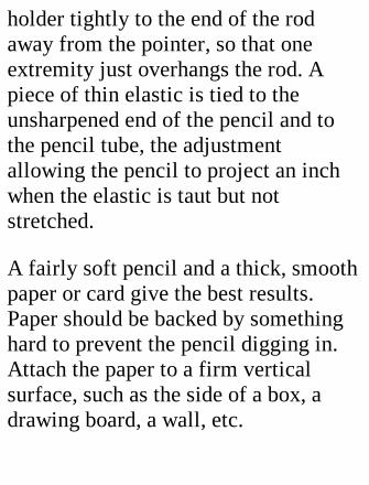
holder tightly to the end of the rodaway from the pointer, so that oneextremity just overhangs the rod. Apiece of thin elastic is tied to theunsharpened end of the pencil and tothe pencil tube, the adjustmentallowing the pencil to project an inchwhen the elastic is taut but notstretched.
A fairly soft pencil and a thick, smoothpaper or card give the best results.Paper should be backed by somethinghard to prevent the pencil digging in.Attach the paper to a firm verticalsurface, such as the side of a box, adrawing board, a wall, etc.
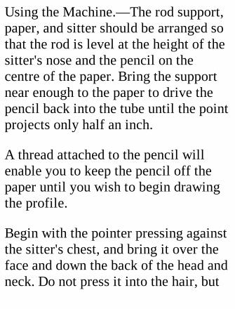
Using the Machine.—The rod support,paper, and sitter should be arranged sothat the rod is level at the height of thesitter's nose and the pencil on thecentre of the paper. Bring the supportnear enough to the paper to drive thepencil back into the tube until the pointprojects only half an inch.
A thread attached to the pencil willenable you to keep the pencil off thepaper until you wish to begin drawingthe profile.
Begin with the pointer pressing againstthe sitter's chest, and bring it over theface and down the back of the head andneck. Do not press it into the hair, but
carry it along what you consider to bethe outline; though it must be in actualcontact with the features and clothes. Itis hardly necessary to mention that thesitter must keep perfectly still if thesilhouette is to be at all accurate.
The tracing is cut round with fine-pointed scissors, and the paper blackedand stuck on a piece of white card.Some trouble is saved by using paperwhite on one aide and black on theother. If duplicates are needed, two ormore pieces of paper should be stucktogether by the corners and to the paperon which the silhouette is drawn, andall be cut through at one operation.
With a little practice the actual tracingof the outline occupies but a fewseconds. Things are expedited if anassistant adjusts the paper and pencil.
XXXVIII. A SIGNALLINGLAMP.
Visual signalling is effected at night inthe Morse code by means of a lampfitted with an easily-moved shutter,which passes or cuts off the light at thewill of the operator. Readers who knowthe Morse code might well go to thetrouble of constructing in duplicate the
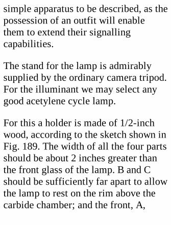
simple apparatus to be described, as thepossession of an outfit will enablethem to extend their signallingcapabilities.
The stand for the lamp is admirablysupplied by the ordinary camera tripod.For the illuminant we may select anygood acetylene cycle lamp.
For this a holder is made of 1/2-inchwood, according to the sketch shown inFig. 189. The width of all the four partsshould be about 2 inches greater thanthe front glass of the lamp. B and Cshould be sufficiently far apart to allowthe lamp to rest on the rim above thecarbide chamber; and the front, A,
should be at least an inch higher thanthe top of the lamp glass.
[Illustration: FIG. 189.—Signallinglamp with quick-moving shutter.]
The hole cut in B must be so situated asto bring the front of the lamp close tothe front of the holder, so that thegreatest possible amount of light maybe utilized. The hole in A should berather larger than the lamp front, and,of course, be accurately centred. Markthese two holes off carefully, and cutout with a pad saw or fret saw.
A socket must be attached to the centreof the underside of the base to take thecamera screw; or, if such a socket is

not easily obtainable, a hole should bedrilled in the base to take an ordinarywood screw of good size, the surplus ofwhich is cut off so as not to interferewith the lamp.
The Shutter.—The woodwork is sosimple that nothing further need besaid about it. The more difficult part ofthe business is the making of theshutter, which must be so constructedthat it can be opened and closed rapidlyby motions similar to those used inworking the telegraph key described ina preceding chapter. Speed of workingis obtained by dividing the shutter intotwo or three parts, each revolving on itsown spindle, but all connected so as to

act in perfect unison. The thinnestsheet brass or iron obtainable should beused, so that the tension of the springused to close the shutter need not begreat. Our illustration shows a two-partshutter, each half an inch wider thanthe hole in the front, and jointly asimilar amount deeper. The upper halfoverlaps the lower, outside, by aquarter of an inch.
The spindles are two straight pieces ofbrass wire, revolving in sockets whichare most easily made of notched piecesof wood (as shown in Fig. 189), withremovable caps of strip tin. The lowerspindle should be an inch longer thanthe width of the front, to allow for a
cranked end, to which the closingspring will be attached.
Having cut out the halves of theshutter, solder the spindle wires to oneedge of each on what will be the backside. The wires must be so arranged asto allow a quarter of an inch to projectbeyond the left edge of the front, as theopening mechanism is situated on thisside as the most convenient for theoperator.
Take a couple of metal discs, an inch orso in diameter, and bore a hole in eachnear the circumference to fit the endsof the pivots fairly tight. Three-eighthsof an inch from this—centre to centre
—bore and tap a hole for a smallscrew. The tapping should be done witha taper tap and carried just so far thatthe screw turns stiffly without dangerof being broken off by the screw-driver.
Next find the correct positions of theparts of the shutter and the spindlesockets on the front of the holder, andmark them off carefully. Screw thewooden parts of the sockets to thefront. Four little "distance pieces"should now be cut out of small tubing,or made by twisting tin round thespindle, to place on the spindlesbetween shutter and sockets, so that theshutters cannot shift sideways.
The right-hand end of the lower spindlemust be bent over (after slipping on thedistance piece) to form a 1/2-inchcrank making an angle of 45 degreeswith the line of the front, in an upwarddirection, as it will be depressed by theopening of the shutter. Flatten out theend with a hammer, and drill a smallhole near the tip.
The shutters can now be placed inposition, and the caps of the sockets bescrewed on. The next thing to make isthe connecting rod to join the cranks atthe left side of the front. For thispurpose we may use a piece of fairlystiff strip metal—brass by preference—5 or 6 inches long. Half an inch from
one end make a mark with the centrepunch; then measure off exactly thedistance between the shutter spindles,and make a second punch mark. Drillholes at the marks large enough, for thedisc screws to pass through easily, butnot loosely.
Attach the rod to the discs by thescrews, and slip the discs on to the endsof the shutter spindles. (The free end ofthe rod should be upwards.) Press theshutters against the front so that theycannot open, adjust the discs at anangle of 45 degrees to the front in anupward direction, and solder themfirmly to the spindles.
The upper end of the connecting rodshould be turned over to form a fingerrest, or be sharpened off to take a knob.The last operation is the fitting of thespring to close the shutter. A spiralspring attached at one end of the crankon the lower spindle and at the other toa nail projecting from the side of thefront is the most convenientarrangement. If you have not got aspiral spring, you can easily make a.fairly efficient substitute out of hardbrass wire wound a few times round alarge wire nail.
An alternative method of springing isto add an arm, a, to the connecting rod,as shown by dotted lines in Fig. 189,
and to use the projection for engaging aspring, made by winding hard brasswire a few times round a nail. A screwpassed through the coil holds it to thefront.
The tension of the spring must be justsufficient to close the shutter smartlyand prevent it rebounding far enough topass any light.
XXXIX. A MINIATUREGASWORKS.
The most primitive method of making

coal gas on a small scale is to fill a tin—which must have folded, notsoldered, joints—with small coal,punch a hole in the bottom, and place itlid downwards in the fire. Gas soonbegins to issue, but, owing to thequantity of moisture and impuritiespresent, it will not ignite until someminutes have elapsed. The flame, whenit does make its appearance, is verysmoky and gives little light, because, inaddition to the coal gas of commerce,there are present ammonia gas,sulphuretted hydrogen, carbonic acid,tar vapour, etc., which preventbrightness of flame.
[Illustration: FIG. 190.—General view
of gas-making apparatus.]
A miniature gasworks, if it is to beworthy of its name, must obviouslyendeavour to separate the troublesomecomponents from the useful gas. Thedoing of this involves severalprocesses, all simple enough inprinciple, and requiring but simpleapparatus for demonstration on a smallscale. To take them in order theprocesses are—
(l) The formation of gas in a retort;
(2) The condensation of the tar;
(3) The condensation of steam;
(4) The removal of the ammonia gas;
(5) The removal of the sulphurettedhydrogen and carbonic acid.
The last two processes are, in a realgasworks, usually separated, but forsimplicity's sake we will combinethem. Finally, the storage of the gashas to be provided for.
The Retort.—To get very good results,the retort should be of cast iron, andhave a removable air-tight cover; but,to keep down expense, we will use anordinary 2-pound self-opening coffeetin. A short piece of brass pipe issoldered into the lid near one edge tocarry off the gas as it is generated. To

get a fairly gas-tight joint, red-leadedasbestos string should be rammedtightly between the lid and the tin. Thetin may be laid on an open fire on theslant, the lid end uppermost, and thepipe at the top, where the gas willcollect; or, if you wish to make thingsmore realistic, you may easilyconstruct an oven with sides and backof fire-brick, and front of sheet iron,through the hole in which the tin ispushed horizontally, so that only halfan inch projects. This is a. suitablearrangement for out of doors.
[Illustration: FIG. 191.—Verticalsection of condenser.]
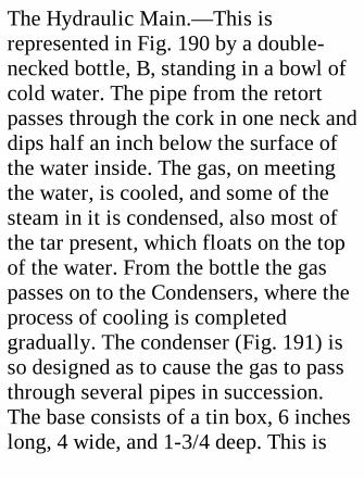
The Hydraulic Main.—This isrepresented in Fig. 190 by a double-necked bottle, B, standing in a bowl ofcold water. The pipe from the retortpasses through the cork in one neck anddips half an inch below the surface ofthe water inside. The gas, on meetingthe water, is cooled, and some of thesteam in it is condensed, also most ofthe tar present, which floats on the topof the water. From the bottle the gaspasses on to the Condensers, where theprocess of cooling is completedgradually. The condenser (Fig. 191) isso designed as to cause the gas to passthrough several pipes in succession.The base consists of a tin box, 6 incheslong, 4 wide, and 1-3/4 deep. This is
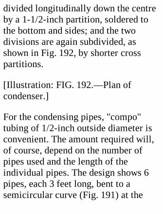
divided longitudinally down the centreby a 1-1/2-inch partition, soldered tothe bottom and sides; and the twodivisions are again subdivided, asshown in Fig. 192, by shorter crosspartitions.
[Illustration: FIG. 192.—Plan ofcondenser.]
For the condensing pipes, "compo"tubing of 1/2-inch outside diameter isconvenient. The amount required will,of course, depend on the number ofpipes used and the length of theindividual pipes. The design shows 6pipes, each 3 feet long, bent to asemicircular curve (Fig. 191) at the
middle to form very long, narrowhorse-shoes. The pipes are supported atthe curve by the crossbar, S (Fig. 191),of a frame, and their ends enter shortpieces of brass tubing soldered intoholes in the bottom of the tin box.Rubber bands make the joints air-tight.
[Illustration: FIG. 193.—Verticalsection of purifier.]
The base is stood bottom upwards in alarger tin containing an inch and a halfof water. The water acts as a seal,preventing the passage of the gas fromone compartment to another throughthe pipes which it traverses, in theorder indicated by the arrows and
numbers in Fig. 192, to reach theoutlet. On its way the gas is deprived ofany water and of any traces of tar. Thecondensed water and tar fall from theopen ends of the pipes into the base.
The Purifier is made of a large tin withoverlapping lid. Near the bottom issoldered on an inlet pipe; just belowthe lid an outlet pipe. Cut out two discsof perforated zinc or sheet tin to fitinside the tin easily, but not loosely. (Iftin is used, make a number of smallholes in it.) The lower of the discs (Fig.193, Bl) has three wire legs, AA,soldered to it, to support the upper disc,B. Three short supports keep it clear ofthe bottom.
The tin must be charged with a mixtureof two parts green sulphate of iron andone part lime. The lime should beslaked a short time before use. Thesulphate, lime, and sufficient water tomoisten the whole are ground into apulp and left to dry. The dry mixture,which has a reddish-yellow colour, isbroken up fine. Put tray B1 into placeand spread half the chemical over it;then lay B on the top and cover it withthe remainder. The lid joint is sealedby a broad rubber band.
While passing through the tin, theammonia, sulphuretted hydrogen andcarbonic acid gases all combine withthe chemical, and fairly pure gas issues
from the outlet.
The Gasholder.—As the gasometer isan important feature of a gasworks, oursmall plant should contain itscounterpart, as it serves to regulate thepressure of the gas, and, therefore, thesteadiness of the flame, as well asaffording storage room.
As a gasometer, one may use acontainer made on the principle of thelung-testing apparatus described on p.361; or the gasholder of a lanternacetylene apparatus, which must, ofcourse, be suitably counterweighted.
Working the Plant.—When starting upthe plant, leave the burner open until
inflammable gas issues, so that the airpresent in the various chambers may bedisplaced.
[Transcribers note: Premature lightingof the burner may cause the flame topropagate into the system and explode.I speak from experience.]
INDEX.
Aeroplane, model, self-launching.Bedplate for engine.Bellows, double.Bench, joiner's.Benham's harmonograph.Bicycle shed.
Boilers, model.Bookstand.Box kites.
Cabinets, cardboard, cigar-box, match-box, tool.Circles, rolling.Clock, electric alarm.Colour top.Cylinder, double-acting steam.
Developing sink.Doors for shed.Double-acting horizontal steam engine.Double bellows.
Eccentrics.Electric alarm clock.Electric motor, reciprocating.

Electric railway.Engine, hot-air.Experiments, apparatus for simplescientific.
Fuels for model boilers.
Gasworks, miniature.Ganges, rain, water,Gimbals, or universal joints.Gliders, paper.Goold's harmonograph.Governor for engine.
Harmonographs.Hot-air engines.House ladder.
Joiner's bench.
Kettles, quick-boiling.Kites, box.Kite winders.
Ladder, house.Lamp, signalling.Locomotive, electric.Lung-testing apparatus.Magic swingers.windmill.Match-boarding.Match-box, self-supplying.Morse code.Morse sounder.Motor, electric.Motor, water.
Nozzle for steam turbine.

Pantograph.Pendulums for harmonograph.Pens for harmonograph.Pneumatic puzzle.Poultry house.Propellers for aeroplane.Pumps.Puppets, wrestling.Puzzle, pneumatic.
Railway, electric.Rain gauges.Reciprocating steam engine, simple.Resistance, adjustable, for electricrailway.Reversing switch for electric railway.Riveting.
Safety Valves.Sawing trestle.Shed for bicycle.Signalling lamp.Silhouette drawing machine.Simple scientific experiments.Sink, developing.Slide valve.Smoke-ring apparatus.Soldering.Spokes, magic.Steam cocks.Steam engines.Steam gauge.Steam pump.Steam tops.Steam turbines.Strength. testing machines.
Swingers, magic.Switch, multiple battery.Switch, reversing.
Target apparatus.Telegraphic apparatus.Testing boilers.Tool cabinet.Top, colour.Tops, steam.Track for model railway.Trestle, sawing.Turbines, model steam.
Vanishing spiral.Vice for Joiner's bench.
Water gauge.Water motor.
Weights for harmonograph pendulums.Windmill, magic.Wind vanes; electric.Workbox, Norwegian.Wrestling puppets.Wriggling line.
THE END.
PRINTED IN GREAT BRITAIN AT THEPRESS OF THE PUBLISHERS.
End of the Project Gutenberg EBook ofThings To Make, by Archibald

Williams
*** END OF THIS PROJECTGUTENBERG EBOOK THINGS TOMAKE ***
***** This file should be named14664.txt or 14664.zip ***** This andall associated files of various formatswill be found in:http://www.gutenberg.net/1/4/6/6/14664/
Produced by Don Kostuch
Updated editions will replace theprevious one—the old editions will berenamed.
Creating the works from public domain

print editions means that no one owns aUnited States copyright in these works,so the Foundation (and you!) can copyand distribute it in the United Stateswithout permission and without payingcopyright royalties. Special rules, setforth in the General Terms of Use partof this license, apply to copying anddistributing Project Gutenberg-tmelectronic works to protect thePROJECT GUTENBERG-tm conceptand trademark. Project Gutenberg is aregistered trademark, and may not beused if you charge for the eBooks,unless you receive specific permission.If you do not charge anything forcopies of this eBook, complying withthe rules is very easy. You may use this

eBook for nearly any purpose such ascreation of derivative works, reports,performances and research. They maybe modified and printed and givenaway—you may do practicallyANYTHING with public domaineBooks. Redistribution is subject to thetrademark license, especiallycommercial redistribution.
*** START: FULLLICENSE ***
THE FULL PROJECT GUTENBERGLICENSE PLEASE READ THIS BEFORE

YOU DISTRIBUTE OR USE THIS WORK
To protect the Project Gutenberg-tmmission of promoting the freedistribution of electronic works, byusing or distributing this work (or anyother work associated in any way withthe phrase "Project Gutenberg"), youagree to comply with all the terms ofthe Full Project Gutenberg-tm License(available with this file or online athttp://gutenberg.net/license).
Section 1. General Terms of Use andRedistributing Project Gutenberg-tmelectronic works

1.A. By reading or using any part ofthis Project Gutenberg-tm electronicwork, you indicate that you have read,understand, agree to and accept all theterms of this license and intellectualproperty (trademark/copyright)agreement. If you do not agree to abideby all the terms of this agreement, youmust cease using and return or destroyall copies of Project Gutenberg-tmelectronic works in your possession. Ifyou paid a fee for obtaining a copy ofor access to a Project Gutenberg-tmelectronic work and you do not agree tobe bound by the terms of thisagreement, you may obtain a refundfrom the person or entity to whom youpaid the fee as set forth in paragraph

1.E.8.
1.B. "Project Gutenberg" is a registeredtrademark. It may only be used on orassociated in any way with anelectronic work by people who agree tobe bound by the terms of thisagreement. There are a few things thatyou can do with most ProjectGutenberg-tm electronic works evenwithout complying with the full termsof this agreement. See paragraph 1.Cbelow. There are a lot of things you cando with Project Gutenberg-tmelectronic works if you follow theterms of this agreement and helppreserve free future access to ProjectGutenberg-tm electronic works. See

paragraph 1.E below.
1.C. The Project Gutenberg LiteraryArchive Foundation ("the Foundation"or PGLAF), owns a compilationcopyright in the collection of ProjectGutenberg-tm electronic works. Nearlyall the individual works in thecollection are in the public domain inthe United States. If an individual workis in the public domain in the UnitedStates and you are located in the UnitedStates, we do not claim a right toprevent you from copying, distributing,performing, displaying or creatingderivative works based on the work aslong as all references to ProjectGutenberg are removed. Of course, we

hope that you will support the ProjectGutenberg-tm mission of promotingfree access to electronic works byfreely sharing Project Gutenberg-tmworks in compliance with the terms ofthis agreement for keeping the ProjectGutenberg-tm name associated with thework. You can easily comply with theterms of this agreement by keeping thiswork in the same format with itsattached full Project Gutenberg-tmLicense when you share it withoutcharge with others.
1.D. The copyright laws of the placewhere you are located also govern whatyou can do with this work. Copyrightlaws in most countries are in a constant

state of change. If you are outside theUnited States, check the laws of yourcountry in addition to the terms of thisagreement before downloading,copying, displaying, performing,distributing or creating derivativeworks based on this work or any otherProject Gutenberg-tm work. TheFoundation makes no representationsconcerning the copyright status of anywork in any country outside the UnitedStates.
1.E. Unless you have removed allreferences to Project Gutenberg:
1.E.1. The following sentence, withactive links to, or other immediate

access to, the full Project Gutenberg-tm License must appear prominentlywhenever any copy of a ProjectGutenberg-tm work (any work onwhich the phrase "Project Gutenberg"appears, or with which the phrase"Project Gutenberg" is associated) isaccessed, displayed, performed,viewed, copied or distributed:
This eBook is for the use of anyoneanywhere at no cost and with almost norestrictions whatsoever. You may copyit, give it away or re-use it under theterms of the Project Gutenberg Licenseincluded with this eBook or online atwww.gutenberg.net

1.E.2. If an individual ProjectGutenberg-tm electronic work isderived from the public domain (doesnot contain a notice indicating that it isposted with permission of thecopyright holder), the work can becopied and distributed to anyone in theUnited States without paying any feesor charges. If you are redistributing orproviding access to a work with thephrase "Project Gutenberg" associatedwith or appearing on the work, youmust comply either with therequirements of paragraphs 1.E.1through 1.E.7 or obtain permission forthe use of the work and the ProjectGutenberg-tm trademark as set forth inparagraphs 1.E.8 or 1.E.9.

1.E.3. If an individual ProjectGutenberg-tm electronic work is postedwith the permission of the copyrightholder, your use and distribution mustcomply with both paragraphs 1.E.1through 1.E.7 and any additional termsimposed by the copyright holder.Additional terms will be linked to theProject Gutenberg-tm License for allworks posted with the permission ofthe copyright holder found at thebeginning of this work.
1.E.4. Do not unlink or detach orremove the full Project Gutenberg-tmLicense terms from this work, or anyfiles containing a part of this work orany other work associated with Project

Gutenberg-tm.
1.E.5. Do not copy, display, perform,distribute or redistribute this electronicwork, or any part of this electronicwork, without prominently displayingthe sentence set forth in paragraph1.E.1 with active links or immediateaccess to the full terms of the ProjectGutenberg-tm License.
1.E.6. You may convert to anddistribute this work in any binary,compressed, marked up, nonproprietaryor proprietary form, including anyword processing or hypertext form.However, if you provide access to ordistribute copies of a Project

Gutenberg-tm work in a format otherthan "Plain Vanilla ASCII" or otherformat used in the official versionposted on the official ProjectGutenberg-tm web site(www.gutenberg.net), you must, at noadditional cost, fee or expense to theuser, provide a copy, a means ofexporting a copy, or a means ofobtaining a copy upon request, of thework in its original "Plain VanillaASCII" or other form. Any alternateformat must include the full ProjectGutenberg-tm License as specified inparagraph 1.E.1.
1.E.7. Do not charge a fee for access to,viewing, displaying, performing,

copying or distributing any ProjectGutenberg-tm works unless youcomply with paragraph 1.E.8 or 1.E.9.
1.E.8. You may charge a reasonable feefor copies of or providing access to ordistributing Project Gutenberg-tmelectronic works provided that
- You pay a royalty fee of 20% of thegross profits you derive from the use ofProject Gutenberg-tm works calculatedusing the method you already use tocalculate your applicable taxes. The feeis owed to the owner of the ProjectGutenberg-tm trademark, but he hasagreed to donate royalties under thisparagraph to the Project Gutenberg

Literary Archive Foundation. Royaltypayments must be paid within 60 daysfollowing each date on which youprepare (or are legally required toprepare) your periodic tax returns.Royalty payments should be clearlymarked as such and sent to the ProjectGutenberg Literary Archive Foundationat the address specified in Section 4,"Information about donations to theProject Gutenberg Literary ArchiveFoundation."
- You provide a full refund of anymoney paid by a user who notifies youin writing (or by e-mail) within 30 daysof receipt that s/he does not agree tothe terms of the full Project Gutenberg-

tm License. You must require such auser to return or destroy all copies ofthe works possessed in a physicalmedium and discontinue all use of andall access to other copies of ProjectGutenberg-tm works.
- You provide, in accordance withparagraph 1.F.3, a full refund of anymoney paid for a work or areplacement copy, if a defect in theelectronic work is discovered andreported to you within 90 days ofreceipt of the work.
- You comply with all other terms ofthis agreement for free distribution ofProject Gutenberg-tm works.
1.E.9. If you wish to charge a fee ordistribute a Project Gutenberg-tmelectronic work or group of works ondifferent terms than are set forth in thisagreement, you must obtain permissionin writing from both the ProjectGutenberg Literary Archive Foundationand Michael Hart, the owner of theProject Gutenberg-tm trademark.Contact the Foundation as set forth inSection 3 below.
1.F.
1.F.1. Project Gutenberg volunteers andemployees expend considerable effortto identify, do copyright research on,transcribe and proofread public domain

works in creating the ProjectGutenberg-tm collection. Despite theseefforts, Project Gutenberg-tmelectronic works, and the medium onwhich they may be stored, may contain"Defects," such as, but not limited to,incomplete, inaccurate or corrupt data,transcription errors, a copyright orother intellectual propertyinfringement, a defective or damageddisk or other medium, a computervirus, or computer codes that damageor cannot be read by your equipment.
1.F.2. LIMITED WARRANTY,DISCLAIMER OF DAMAGES -Except for the "Right of Replacementor Refund" described in paragraph

1.F.3, the Project Gutenberg LiteraryArchive Foundation, the owner of theProject Gutenberg-tm trademark, andany other party distributing a ProjectGutenberg-tm electronic work underthis agreement, disclaim all liability toyou for damages, costs and expenses,including legal fees. YOU AGREETHAT YOU HAVE NO REMEDIESFOR NEGLIGENCE, STRICTLIABILITY, BREACH OFWARRANTY OR BREACH OFCONTRACT EXCEPT THOSEPROVIDED IN PARAGRAPH F3.YOU AGREE THAT THEFOUNDATION, THE TRADEMARKOWNER, AND ANY DISTRIBUTORUNDER THIS AGREEMENT WILL

NOT BE LIABLE TO YOU FORACTUAL, DIRECT, INDIRECT,CONSEQUENTIAL, PUNITIVE ORINCIDENTAL DAMAGES EVEN IFYOU GIVE NOTICE OF THEPOSSIBILITY OF SUCH DAMAGE.
1.F.3. LIMITED RIGHT OFREPLACEMENT OR REFUND - Ifyou discover a defect in this electronicwork within 90 days of receiving it,you can receive a refund of the money(if any) you paid for it by sending awritten explanation to the person youreceived the work from. If you receivedthe work on a physical medium, youmust return the medium with yourwritten explanation. The person or

entity that provided you with thedefective work may elect to provide areplacement copy in lieu of a refund. Ifyou received the work electronically,the person or entity providing it to youmay choose to give you a secondopportunity to receive the workelectronically in lieu of a refund. If thesecond copy is also defective, you maydemand a refund in writing withoutfurther opportunities to fix theproblem.
1.F.4. Except for the limited right ofreplacement or refund set forth inparagraph 1.F.3, this work is providedto you 'AS-IS' WITH NO OTHERWARRANTIES OF ANY KIND,
EXPRESS OR IMPLIED, INCLUDINGBUT NOT LIMITED TOWARRANTIES OFMERCHANTIBILITY OR FITNESSFOR ANY PURPOSE.
1.F.5. Some states do not allowdisclaimers of certain impliedwarranties or the exclusion orlimitation of certain types of damages.If any disclaimer or limitation set forthin this agreement violates the law ofthe state applicable to this agreement,the agreement shall be interpreted tomake the maximum disclaimer orlimitation permitted by the applicablestate law. The invalidity orunenforceability of any provision of

this agreement shall not void theremaining provisions.
1.F.6. INDEMNITY - You agree toindemnify and hold the Foundation, thetrademark owner, any agent oremployee of the Foundation, anyoneproviding copies of Project Gutenberg-tm electronic works in accordance withthis agreement, and any volunteersassociated with the production,promotion and distribution of ProjectGutenberg-tm electronic works,harmless from all liability, costs andexpenses, including legal fees, thatarise directly or indirectly from any ofthe following which you do or cause tooccur: (a) distribution of this or any

Project Gutenberg-tm work, (b)alteration, modification, or additions ordeletions to any Project Gutenberg-tmwork, and (c) any Defect you cause.
Section 2. Information about theMission of Project Gutenberg-tm
Project Gutenberg-tm is synonymouswith the free distribution of electronicworks in formats readable by thewidest variety of computers includingobsolete, old, middle-aged and newcomputers. It exists because of theefforts of hundreds of volunteers anddonations from people in all walks oflife.

Volunteers and financial support toprovide volunteers with the assistancethey need, is critical to reachingProject Gutenberg-tm's goals andensuring that the Project Gutenberg-tmcollection will remain freely availablefor generations to come. In 2001, theProject Gutenberg Literary ArchiveFoundation was created to provide asecure and permanent future for ProjectGutenberg-tm and future generations.To learn more about the ProjectGutenberg Literary Archive Foundationand how your efforts and donations canhelp, see Sections 3 and 4 and theFoundation web page athttp://www.pglaf.org.

Section 3. Information about theProject Gutenberg Literary ArchiveFoundation
The Project Gutenberg LiteraryArchive Foundation is a non profit501(c)(3) educational corporationorganized under the laws of the state ofMississippi and granted tax exemptstatus by the Internal Revenue Service.The Foundation's EIN or federal taxidentification number is 64-6221541.Its 501(c)(3) letter is posted athttp://pglaf.org/fundraising.Contributions to the Project GutenbergLiterary Archive Foundation are taxdeductible to the full extent permittedby U.S. federal laws and your state's

laws.
The Foundation's principal office islocated at 4557 Melan Dr. S. Fairbanks,AK, 99712., but its volunteers andemployees are scattered throughoutnumerous locations. Its business officeis located at 809 North 1500 West, SaltLake City, UT 84116, (801) 596-1887,email [email protected]. Emailcontact links and up to date contactinformation can be found at theFoundation's web site and official pageat http://pglaf.org
For additional contact information: Dr. Gregory B. Newby Chief Executive and Director

Section 4. Information aboutDonations to the Project GutenbergLiterary Archive Foundation
Project Gutenberg-tm depends uponand cannot survive without wide spreadpublic support and donations to carryout its mission of increasing thenumber of public domain and licensedworks that can be freely distributed inmachine readable form accessible bythe widest array of equipmentincluding outdated equipment. Manysmall donations ($1 to $5,000) areparticularly important to maintaining

tax exempt status with the IRS.
The Foundation is committed tocomplying with the laws regulatingcharities and charitable donations in all50 states of the United States.Compliance requirements are notuniform and it takes a considerableeffort, much paperwork and many feesto meet and keep up with theserequirements. We do not solicitdonations in locations where we havenot received written confirmation ofcompliance. To SEND DONATIONS ordetermine the status of compliance forany particular state visithttp://pglaf.org

While we cannot and do not solicitcontributions from states where wehave not met the solicitationrequirements, we know of noprohibition against acceptingunsolicited donations from donors insuch states who approach us with offersto donate.
International donations are gratefullyaccepted, but we cannot make anystatements concerning tax treatment ofdonations received from outside theUnited States. U.S. laws alone swampour small staff.

Please check the Project GutenbergWeb pages for current donationmethods and addresses. Donations areaccepted in a number of other waysincluding including checks, onlinepayments and credit card donations. Todonate, please visit:http://pglaf.org/donate
Section 5. General InformationAbout Project Gutenberg-tmelectronic works.
Professor Michael S. Hart is theoriginator of the Project Gutenberg-tmconcept of a library of electronic worksthat could be freely shared with

anyone. For thirty years, he producedand distributed Project Gutenberg-tmeBooks with only a loose network ofvolunteer support.
Project Gutenberg-tm eBooks are oftencreated from several printed editions,all of which are confirmed as PublicDomain in the U.S. unless a copyrightnotice is included. Thus, we do notnecessarily keep eBooks in compliancewith any particular paper edition.
Most people start at our Web sitewhich has the main PG search facility:
http://www.gutenberg.net

This Web site includes informationabout Project Gutenberg-tm, includinghow to make donations to the ProjectGutenberg Literary ArchiveFoundation, how to help produce ournew eBooks, and how to subscribe toour email newsletter to hear about neweBooks.