Embed Size (px)
Citation preview

Proceedings of the 24th ITTC - Volume I 73
The Propulsion Committee
Final Report and Recommendations to the 24th ITTC
1. INTRODUCTION
1.1 Membership and Meetings
The Members of the Propulsion Committee of the 24th International Towing Tank Conference were as follows:
Prof. Anthony F. Molland (Chairman).
University of Southampton, UK. Dr. Ki-Han Kim (Secretary).
Naval Surface Warfare Center, U.S.A. Mr. Lilian Descotte (until August 2004).
Bassin d’Essais des Carènes, France. Mr. Erwan Jacquin (from September 2004).
Bassin d’Essais des Carènes, France. Mr. Hans-Jürgen Heinke.
Schiffbau Versuchsanstalt Potsdam, Germany.
Dr. Tatsuro Kudo (until April 2003). National Maritime Research Institute, Japan.
Dr. Yoshitaka Ukon (from May 2003). National Maritime Research Institute, Japan.
Dr. Anton Minchev. FORCE Technology-DMI, Denmark.
Dr. Francesco Salvatore. Instituto Nazionale per Studi ed Esperienze di Architettura Navale, Italy.
Mr. Deng-Hai Tang. China Ship Scientific Research Centre, China.
Dr. Suak-Ho Van.
Korea Research Institute of Ships and Engineering, Korea.
Four meetings of the Committee were held as follows:
University of Southampton, UK, February
2003. KRISO, Korea, September 2003. INSEAN, Italy, March-April, 2004. DTMB, USA, November 2004.
1.2 Recommendations of the 23rd ITTC
The recommendations for the work of the Propulsion Committee made by the 23rd ITTC were as follows:
1. Review the state-of-the art, comment on
the potential impact of new developments on the ITTC and identify the need for research and development for propulsion systems. Monitor and follow the develop-ment of new experimental techniques and extrapolation methods.
2. Review the ITTC Recommended Proce-dures, benchmark data and test cases for validation and uncertainty analysis and update as required. Identify the require-ments for new procedures, benchmark data, validation and uncertainty analysis and stimulate the research necessary for their preparation.
3. Develop an ITTC Procedure for specify-

74 The Propulsion Committee
ing the accuracy of model propeller geometry required for propulsion and cavitation testing.
4. Review the development of numerical de-sign and analysis methods for propulsors.
5. Review design and performance aspects of secondary thrusters, such as tunnel, azi-muthing and dynamic positioning devices.
6. Review developments in prediction and assessment of propulsion issues in shallow water.
7. Review advancements in numerical methods for the computation of propeller induced effective wake, cavitation and induced hull pressures.
8. Review of design issues related to very large propellers for mega container ships, such as vibratory forces, cavitation and bearing forces.
1.3 General Remarks
The Propulsion Committee was able to ad-dress all the tasks assigned to it. Recommenda-tion 6 originally included an assessment of wave wash. This task was identified as being more appropriate to the Resistance Committee and was subsequently moved by the Advisory Council to that Committee.
Reviews of subject areas focus on the last three years, except for those topics not covered in recent Propulsion Committee Reports, which are extended back as necessary to cover a longer time period. During the review of the state-of-the art and ITTC Procedures the work of the Specialist Committees on Validation of Waterjet Tests, Azimuthing Podded Propulsion and Cavitation Erosion was noted. The Committee did not review the development of extrapolation methods, noting that this topic would be dealt with by the Powering Perform-ance Prediction Committee. Liaison with these Committees was maintained where possible in order to minimise duplication of work.
The Committee circulated questionnaires to a number of test tanks to survey the use and
applications of current ITTC Procedures. A summary of the results of the survey and result-ing recommendations are given in Section 3.
A new procedure for the Accuracy of Model Propeller Geometry is described in Section 4. The development of recommended tolerances included a survey of current tank practice. The final recommended procedure is included in the ITTC Quality Manual and is recommended for adoption by the 24th ITTC.
2. REVIEW THE STATE-OF-THE ART Comment on the Potential impact of New Developments on the ITTC and Identify the Need for Research and Development for Propulsion Systems. Monitor and Follow the Development of New Experimental Techniques and Extrapolation Methods
2.1 Introduction
The Propulsion Committee decided to provide only an overview of the developments in waterjets and podded propulsors, as there were Specialist Committees working on these topics, together with an overview of surface piercing propellers and to review in some detail the developments in tip plate propellers, rim-driven propellers, trans-cavitating propellers, composite propellers and experimental tech-niques.
2.2 Overview of Developments
Waterjets - Overview. Waterjets are now being applied to a wide range of ship types and for propulsion power ranging up to about 10,000 kW. Typical ongoing research and developments in waterjet design are reported in Wilson et al. (2003), Chesnakas (2003) and Altosole et al. (2003). Two trends are notice-able from the recent literature on waterjets. One is that sophisticated and thus more accurate flow measurements using LDV are
Proceedings of the 24th ITTC - Volume I 75
being applied such as those reported by Chesnakas (2001), Scherer et al. (2001) and Michael and Chesnakas (2004). Another is the increasing use of CFD tools in predicting the flow inside and around the waterjet that is difficult to measure. It has been demonstrated that CFD tools, particularly using RANS-based methods, can make significant improvements in understanding the complex hull-inlet-pump interactions for waterjet propulsion. Estimating wake and thrust deduction and understanding the influence of scale effect is also being improved by more realistic information on the flow field in and around the hull-waterjet system, such as that reported by Ebert, et al. (2003) and Benini (2004).
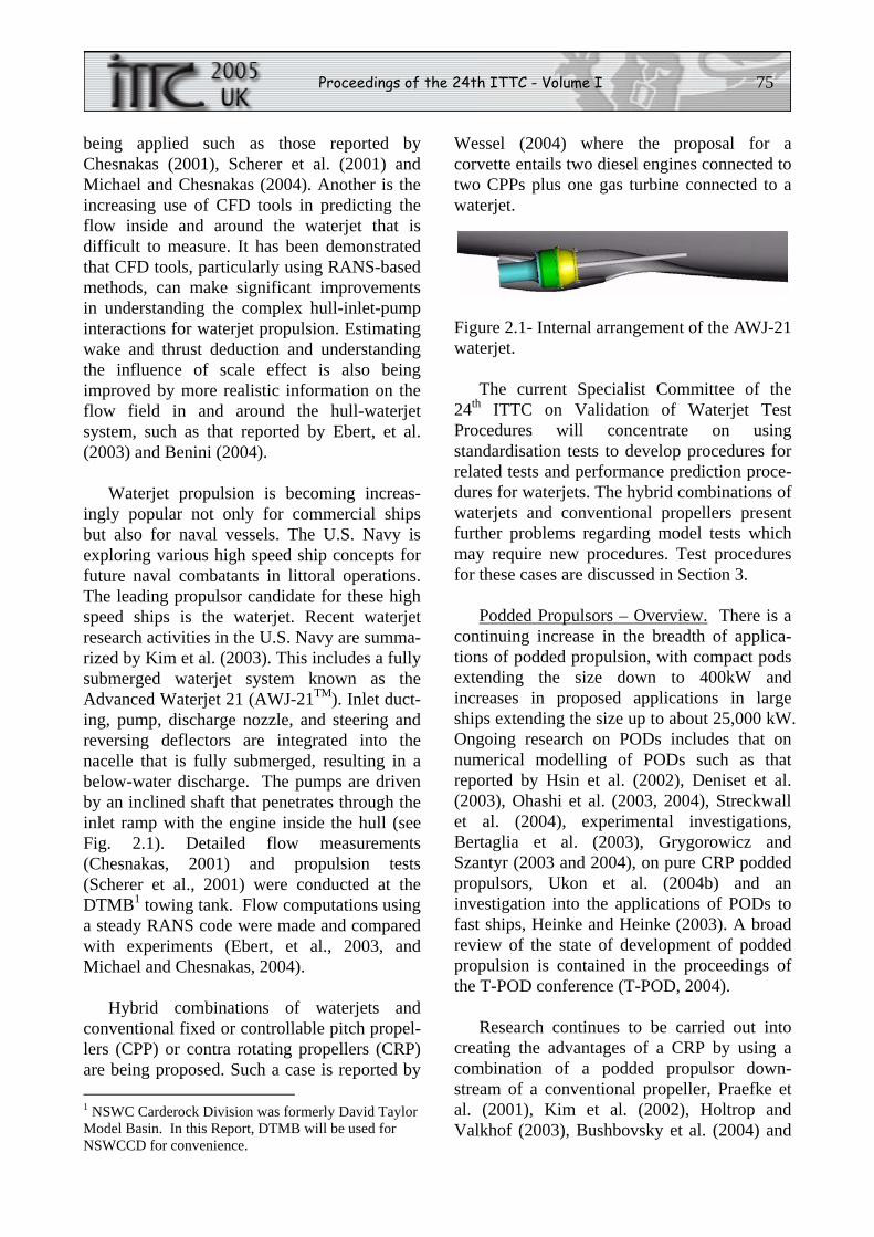
Waterjet propulsion is becoming increas-ingly popular not only for commercial ships but also for naval vessels. The U.S. Navy is exploring various high speed ship concepts for future naval combatants in littoral operations. The leading propulsor candidate for these high speed ships is the waterjet. Recent waterjet research activities in the U.S. Navy are summa-rized by Kim et al. (2003). This includes a fully submerged waterjet system known as the Advanced Waterjet 21 (AWJ-21TM). Inlet duct-ing, pump, discharge nozzle, and steering and reversing deflectors are integrated into the nacelle that is fully submerged, resulting in a below-water discharge. The pumps are driven by an inclined shaft that penetrates through the inlet ramp with the engine inside the hull (see Fig. 2.1). Detailed flow measurements (Chesnakas, 2001) and propulsion tests (Scherer et al., 2001) were conducted at the DTMB1 towing tank. Flow computations using a steady RANS code were made and compared with experiments (Ebert, et al., 2003, and Michael and Chesnakas, 2004).
Hybrid combinations of waterjets and conventional fixed or controllable pitch propel-lers (CPP) or contra rotating propellers (CRP) are being proposed. Such a case is reported by 1 NSWC Carderock Division was formerly David Taylor Model Basin. In this Report, DTMB will be used for NSWCCD for convenience.
Wessel (2004) where the proposal for a corvette entails two diesel engines connected to two CPPs plus one gas turbine connected to a waterjet.
Figure 2.1- Internal arrangement of the AWJ-21 waterjet.
The current Specialist Committee of the 24th ITTC on Validation of Waterjet Test Procedures will concentrate on using standardisation tests to develop procedures for related tests and performance prediction proce-dures for waterjets. The hybrid combinations of waterjets and conventional propellers present further problems regarding model tests which may require new procedures. Test procedures for these cases are discussed in Section 3.
Podded Propulsors – Overview. There is a continuing increase in the breadth of applica-tions of podded propulsion, with compact pods extending the size down to 400kW and increases in proposed applications in large ships extending the size up to about 25,000 kW. Ongoing research on PODs includes that on numerical modelling of PODs such as that reported by Hsin et al. (2002), Deniset et al. (2003), Ohashi et al. (2003, 2004), Streckwall et al. (2004), experimental investigations, Bertaglia et al. (2003), Grygorowicz and Szantyr (2003 and 2004), on pure CRP podded propulsors, Ukon et al. (2004b) and an investigation into the applications of PODs to fast ships, Heinke and Heinke (2003). A broad review of the state of development of podded propulsion is contained in the proceedings of the T-POD conference (T-POD, 2004).
Research continues to be carried out into creating the advantages of a CRP by using a combination of a podded propulsor down-stream of a conventional propeller, Praefke et al. (2001), Kim et al. (2002), Holtrop and Valkhof (2003), Bushbovsky et al. (2004) and
76 The Propulsion Committee
Ohshima and Hoshino (2005). It is an attractive proposition for very large ships where the power can then still be carried on one shaft line. Increased efficiencies can be developed, but several problems can exist regarding unfavour-able interactions between the propellers, particularly if the podded drive is to remain steerable (Frovola et al., 2004). In order to improve the flexibility of machinery layouts, further hybrid combinations are being proposed which entail a mix of two conventional propel-lers plus a centreline podded unit or two podded units with a centreline conventional propeller.
The current Azimuthing Podded Propulsion Committee of the 24th ITTC will concentrate on improving and developing procedures for podded propulsor model tests and the extrapolation of the results to full scale. The contra rotating and other hybrid combinations present further problems regarding model tests and their extrapolation, and test procedures for these cases are discussed in Section 3.
Surface Piercing Propellers - Overview. A thorough review of surface piercing propellers (SPP) was carried out by the 23rd ITTC Propul-sion Committee and reported in 2002. Only ongoing developments since the 23rd ITTC Report and other relevant references are reviewed. In particular, three of the papers reviewed reflect the growing awareness of the importance and influence of hydro-elastic effects on SPPs.
Caponnetto (2003) presents the study of an SPP flow by using the commercial RANS code COMET. This code is based on a finite volume approach and turbulence modelling is achieved via a standard k-ε method. The code is able to analyse complex free surfaces and sliding meshes, and hence it may be used to perform combined analyses of hull and propeller flow. Numerical results on a representative model propeller are compared with available experi-ments to demonstrate the capability of the proposed approach.
Young and Kinnas (2003a,b,c) describe how the 3-D low order boundary element method (BEM) code, PROPCAV, has been extended to predict unsteady hydrodynamic forces and ventilation patterns on SPPs. The coupling of the BEM with a finite element method (FEM) to include hydro-elastic effects is also presented. Further details of the methodology are given in Young (2004). A description of this and other complementary work is given in Section 8.5.
2.3 Tip Plate Propellers
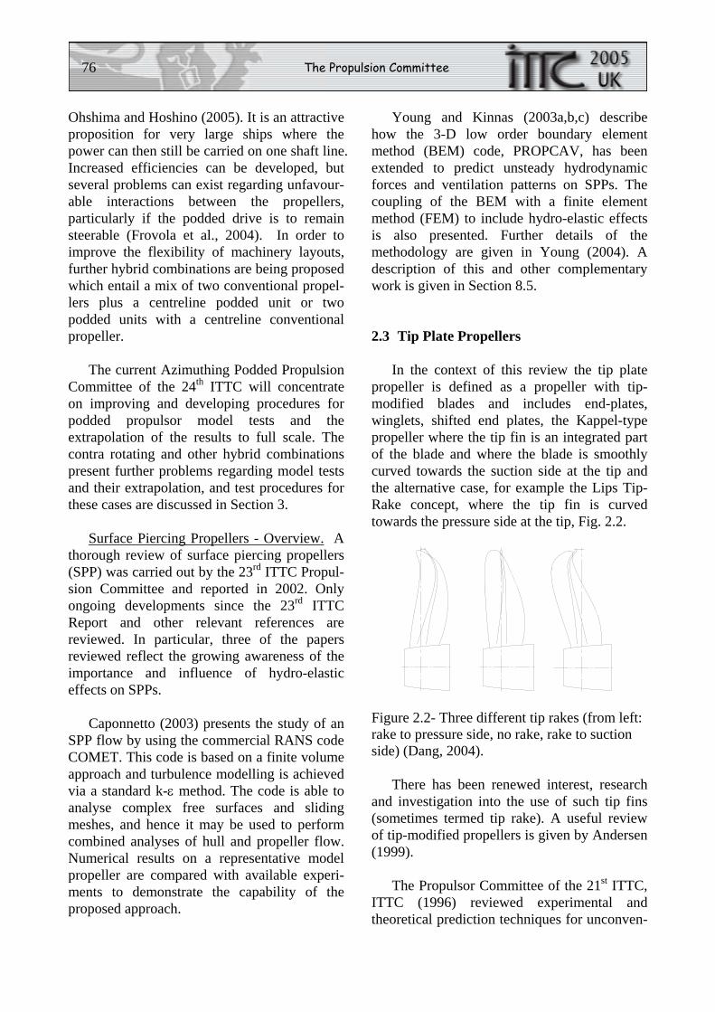
In the context of this review the tip plate propeller is defined as a propeller with tip-modified blades and includes end-plates, winglets, shifted end plates, the Kappel-type propeller where the tip fin is an integrated part of the blade and where the blade is smoothly curved towards the suction side at the tip and the alternative case, for example the Lips Tip-Rake concept, where the tip fin is curved towards the pressure side at the tip, Fig. 2.2.
Figure 2.2- Three different tip rakes (from left: rake to pressure side, no rake, rake to suction side) (Dang, 2004).
There has been renewed interest, research and investigation into the use of such tip fins (sometimes termed tip rake). A useful review of tip-modified propellers is given by Andersen (1999).
The Propulsor Committee of the 21st ITTC, ITTC (1996) reviewed experimental and theoretical prediction techniques for unconven-
Proceedings of the 24th ITTC - Volume I 77
tional methods of propulsion, including the tip plate propeller. The Specialist Committee on Unconventional Propulsors of the 22nd ITTC, ITTC (1999), included a review of tip fin propellers such as end plate, winglet and Kappel propellers. These special geometries are generally only limited modifications to the conventional propeller. It is therefore generally accepted that model tests and scaling of results to full scale can in principle be done in the same way as for a conventional propeller.
Friesch et al. (2003) describe extensive model and full scale investigations for the Kappel propeller. This cooperative research project was funded by the EU research programme KAPRICCIO. The models were tested in open water and behind conditions together with cavitation tests. Comparative full scale sea tests were performed on a product carrier with a conventional propeller and a Kappel propeller. The sea trials demonstrated higher propulsive efficiency with the Kappel propeller than with the conventional propeller. The load distribution on the Kappel propeller deviates from that of a conventional propeller and the frictional component and scale effect of a Kappel propeller is larger than for a conven-tional design. A new surface strip procedure was developed for scaling the frictional forces over the blade.
Atkinson and Andersen (2003) describe stress analysis investigations for the Kappel propeller using FEM. It was found that the inner section of the blade, out to 0.75R, exhibited response characteristics similar to those appropriate to a conventional balanced skew design. In the blade tip region, from approximately 0.8R, the numerical results defining the blade response were of an unex-pected form and it was concluded that these tip response characteristics appear to result from a torsional influence arising out of the combina-tion of blade skew and rake.
The work described by Dang (2004) includes an investigation into the use of tip rake to the pressure side to reduce the intensity
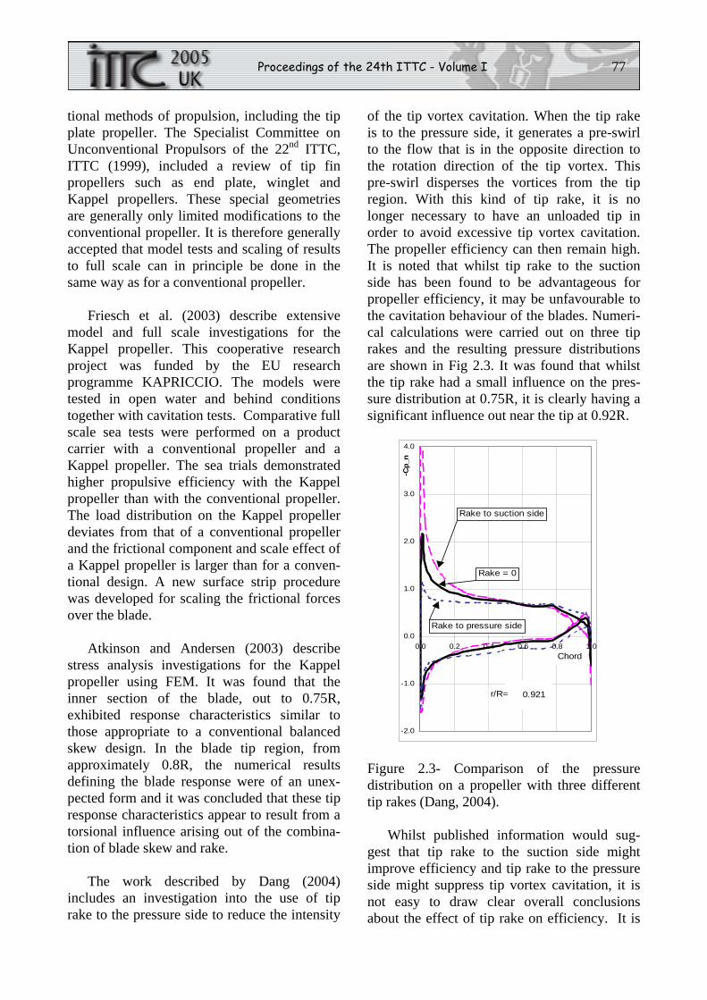
of the tip vortex cavitation. When the tip rake is to the pressure side, it generates a pre-swirl to the flow that is in the opposite direction to the rotation direction of the tip vortex. This pre-swirl disperses the vortices from the tip region. With this kind of tip rake, it is no longer necessary to have an unloaded tip in order to avoid excessive tip vortex cavitation. The propeller efficiency can then remain high. It is noted that whilst tip rake to the suction side has been found to be advantageous for propeller efficiency, it may be unfavourable to the cavitation behaviour of the blades. Numeri-cal calculations were carried out on three tip rakes and the resulting pressure distributions are shown in Fig 2.3. It was found that whilst the tip rake had a small influence on the pres-sure distribution at 0.75R, it is clearly having a significant influence out near the tip at 0.92R.
-2.0
-1.0
0.0
1.0
2.0
3.0
4.0
0.0 0.2 0.4 0.6 0.8 1.0
-Cp_
n
0.921r/R=
Chord
Rake = 0
Rake to suction side
Rake to pressure side
Figure 2.3- Comparison of the pressure distribution on a propeller with three different tip rakes (Dang, 2004).
Whilst published information would sug-gest that tip rake to the suction side might improve efficiency and tip rake to the pressure side might suppress tip vortex cavitation, it is not easy to draw clear overall conclusions about the effect of tip rake on efficiency. It is
78 The Propulsion Committee
apparent that further verification by numerical and experimental methods is required.
2.4 Rim-Driven Propellers
There has been a growing interest in developing the applications of the rim-driven (or tip-driven) propeller concept. In this concept, a permanent magnetic ring (or band) is attached to the propeller tip and the motor stator is integrated into a surrounding duct whereby the propeller is driven from the blade tips. The ring (or band) is recessed inside the duct with a small water filled gap between the band and the duct. Current proposed applica-tions include propulsors, thrusters and waterjets.
A survey of rim-driven propellers, includ-ing electrical and mechanical drives, is given by Radojcic (1997). Versions of the electrical rim-driven shrouded propeller concept are described in Hansa (1986) and Ship and Boat (1993). More recent developments are described by Van Blarcom et al. (2004), Pashias et al. (2003) and Hughes et al. (2004).
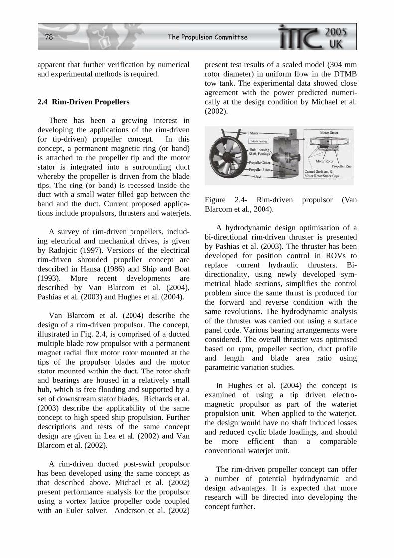
Van Blarcom et al. (2004) describe the design of a rim-driven propulsor. The concept, illustrated in Fig. 2.4, is comprised of a ducted multiple blade row propulsor with a permanent magnet radial flux motor rotor mounted at the tips of the propulsor blades and the motor stator mounted within the duct. The rotor shaft and bearings are housed in a relatively small hub, which is free flooding and supported by a set of downstream stator blades. Richards et al. (2003) describe the applicability of the same concept to high speed ship propulsion. Further descriptions and tests of the same concept design are given in Lea et al. (2002) and Van Blarcom et al. (2002).
A rim-driven ducted post-swirl propulsor has been developed using the same concept as that described above. Michael et al. (2002) present performance analysis for the propulsor using a vortex lattice propeller code coupled with an Euler solver. Anderson et al. (2002)
present test results of a scaled model (304 mm rotor diameter) in uniform flow in the DTMB tow tank. The experimental data showed close agreement with the power predicted numeri-cally at the design condition by Michael et al. (2002).
Figure 2.4- Rim-driven propulsor (Van Blarcom et al., 2004).
A hydrodynamic design optimisation of a bi-directional rim-driven thruster is presented by Pashias et al. (2003). The thruster has been developed for position control in ROVs to replace current hydraulic thrusters. Bi-directionality, using newly developed sym-metrical blade sections, simplifies the control problem since the same thrust is produced for the forward and reverse condition with the same revolutions. The hydrodynamic analysis of the thruster was carried out using a surface panel code. Various bearing arrangements were considered. The overall thruster was optimised based on rpm, propeller section, duct profile and length and blade area ratio using parametric variation studies.
In Hughes et al. (2004) the concept is examined of using a tip driven electro-magnetic propulsor as part of the waterjet propulsion unit. When applied to the waterjet, the design would have no shaft induced losses and reduced cyclic blade loadings, and should be more efficient than a comparable conventional waterjet unit.
The rim-driven propeller concept can offer a number of potential hydrodynamic and design advantages. It is expected that more research will be directed into developing the concept further.
Proceedings of the 24th ITTC - Volume I 79
2.5 Trans-Cavitating Propellers
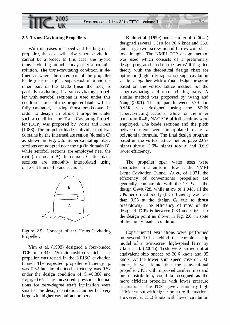
With increases in speed and loading on a propeller, the case will arise where cavitation cannot be avoided. In this case, the hybrid trans-cavitating propeller may offer a potential solution. The trans-cavitating condition is de-fined as where the outer part of the propeller blade (near the tip) is super-cavitating and the inner part of the blade (near the root) is partially cavitating. If a sub-cavitating propel-ler with aerofoil sections is used under this condition, most of the propeller blade will be fully cavitated, causing thrust breakdown. In order to design an efficient propeller under such a condition, the Trans-Cavitating Propel-ler (TCP) was proposed by Vorus and Kress (1988). The propeller blade is divided into two domains by the intermediate region (domain C) as shown in Fig. 2.5. Super-cavitating blade sections are adopted near the tip (in domain B), while aerofoil sections are employed near the root (in domain A). In domain C, the blade sections are smoothly interpolated using different kinds of blade sections.
Figure 2.5- Concept of the Trans-Cavitating Propeller.
Yim et al. (1998) designed a four-bladed TCP for a 34kt-23m air cushion vehicle. The propeller was tested in the KRISO cavitation tunnel. The expected propeller efficiency ηo was 0.62 but the obtained efficiency was 0.57 under the design condition of CT=0.380 and σV0.7R=0.65. The measured pressure fluctua-tions for zero-degree shaft inclination were small at the design cavitation number but very large with higher cavitation numbers.
Kudo et al. (1999) and Ukon et al. (2004a) designed several TCPs for 30.6 knot and 35.0 knot large twin screw inland ferries with shal-low draught. The NMRI TCP design method was used which consists of a preliminary design program based on the Lerbs’ lifting line theory with the theoretical design chart for optimum (high lift/drag ratio) supercavitating sections together with a final design program based on the vortex lattice method for the super-cavitating and non-cavitating parts. A similar method was proposed by Wang and Yang (2001). The tip part between 0.7R and 0.95R was designed using the SRJN supercavitating sections, while for the inner part from 0.4R, NACA16 airfoil sections were employed. The blade sections and the pitch between them were interpolated using a polynomial formula. The final design program based on the vortex lattice method gave 2.0% higher thrust, 2.9% higher torque and 0.6% lower efficiency.
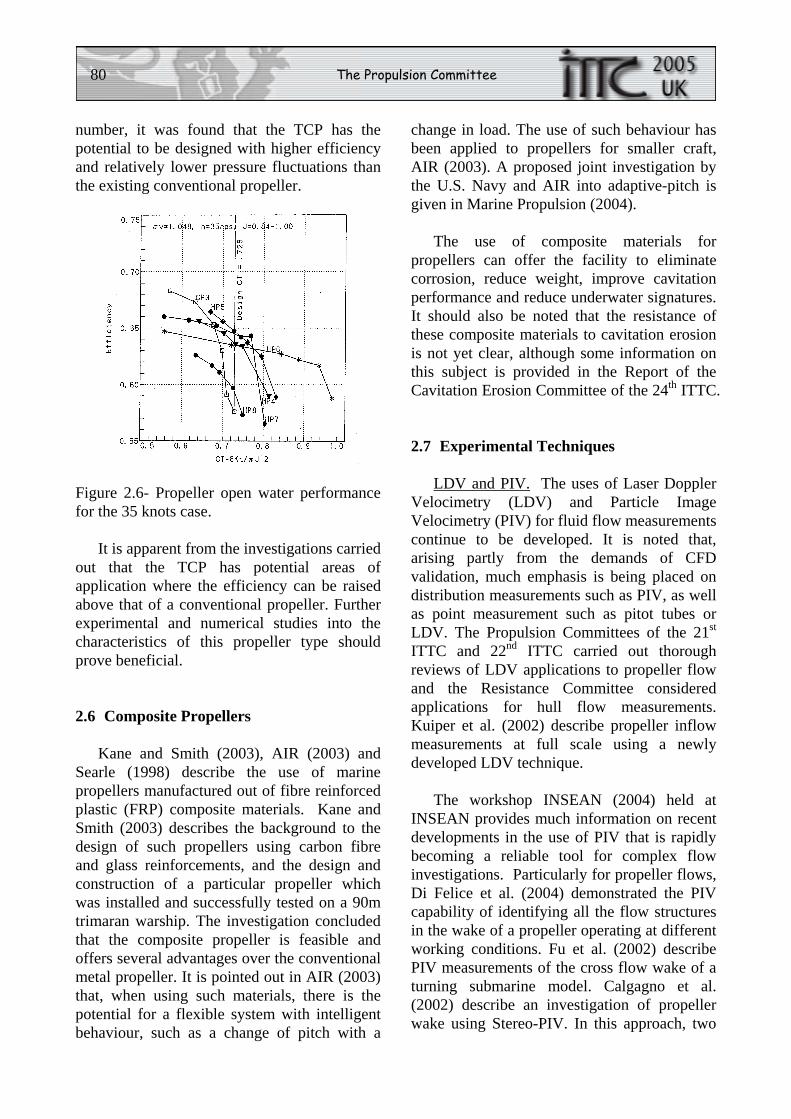
The propeller open water tests were conducted in a uniform flow at the NMRI Large Cavitation Tunnel. At σV of 1.371, the efficiency of conventional propellers are generally comparable with the TCPs at the design CT=0.728, while at σV of 1.048, all the CPs performed poorly (the efficiency was less than 0.58 at the design CT due to thrust breakdown). The efficiency of most of the designed TCPs is between 0.63 and 0.65 near the design point as shown in Fig. 2.6, in spite of the highly loaded condition.
Experimental evaluations were performed on several TCPs behind the complete ship model of a twin-screw high-speed ferry by Ukon et al. (2004a). Tests were carried out at equivalent ship speeds of 30.6 knots and 35 knots. At the lower ship speed case of 30.6 knots, it was found that the conventional propeller CP3, with improved camber lines and pitch distribution, could be designed as the more efficient propeller with lower pressure fluctuations. The TCPs gave a similarly high efficiency but with higher pressure fluctuations. However, at 35.0 knots with lower cavitation
80 The Propulsion Committee
number, it was found that the TCP has the potential to be designed with higher efficiency and relatively lower pressure fluctuations than the existing conventional propeller.
Figure 2.6- Propeller open water performance for the 35 knots case.
It is apparent from the investigations carried out that the TCP has potential areas of application where the efficiency can be raised above that of a conventional propeller. Further experimental and numerical studies into the characteristics of this propeller type should prove beneficial.
2.6 Composite Propellers
Kane and Smith (2003), AIR (2003) and Searle (1998) describe the use of marine propellers manufactured out of fibre reinforced plastic (FRP) composite materials. Kane and Smith (2003) describes the background to the design of such propellers using carbon fibre and glass reinforcements, and the design and construction of a particular propeller which was installed and successfully tested on a 90m trimaran warship. The investigation concluded that the composite propeller is feasible and offers several advantages over the conventional metal propeller. It is pointed out in AIR (2003) that, when using such materials, there is the potential for a flexible system with intelligent behaviour, such as a change of pitch with a
change in load. The use of such behaviour has been applied to propellers for smaller craft, AIR (2003). A proposed joint investigation by the U.S. Navy and AIR into adaptive-pitch is given in Marine Propulsion (2004).
The use of composite materials for propellers can offer the facility to eliminate corrosion, reduce weight, improve cavitation performance and reduce underwater signatures. It should also be noted that the resistance of these composite materials to cavitation erosion is not yet clear, although some information on this subject is provided in the Report of the Cavitation Erosion Committee of the 24th ITTC.
2.7 Experimental Techniques
LDV and PIV. The uses of Laser Doppler Velocimetry (LDV) and Particle Image Velocimetry (PIV) for fluid flow measurements continue to be developed. It is noted that, arising partly from the demands of CFD validation, much emphasis is being placed on distribution measurements such as PIV, as well as point measurement such as pitot tubes or LDV. The Propulsion Committees of the 21st ITTC and 22nd ITTC carried out thorough reviews of LDV applications to propeller flow and the Resistance Committee considered applications for hull flow measurements. Kuiper et al. (2002) describe propeller inflow measurements at full scale using a newly developed LDV technique.
The workshop INSEAN (2004) held at INSEAN provides much information on recent developments in the use of PIV that is rapidly becoming a reliable tool for complex flow investigations. Particularly for propeller flows, Di Felice et al. (2004) demonstrated the PIV capability of identifying all the flow structures in the wake of a propeller operating at different working conditions. Fu et al. (2002) describe PIV measurements of the cross flow wake of a turning submarine model. Calgagno et al. (2002) describe an investigation of propeller wake using Stereo-PIV. In this approach, two
Proceedings of the 24th ITTC - Volume I 81
cameras are used to view the flow from two perspectives allowing the measurement of all three velocity components in a plane. A new fully submersible Stereo-PIV probe has been developed at INSEAN. The system consists of a streamlined torpedo hosting high resolution cameras and laser optics and allows the measurement of the three velocity components at a plane. The system can be configured in different ways in order to match test specifications. The system has been used to survey the evolution of the far wake of a dynamic positioning thruster, El-Lababidy et al. (2004). Lee et al. (2002) describe phase-averaged measurements of propeller wake in which an adaptive hybrid PTV (Particle Tracking Velocimetry) method is used. Compared with PIV, this approach can increase the spatial resolution and measurement accuracy, while reducing the computation time. Pereira and Gharib (2002) describe the use of defocusing digital particle image velocimetry (DDPIV) for the 3-D characterisation of two-phase flows. The DDPIV technique uses a mask with two or more apertures shifted away from the optical axis to obtain multiple images from each scattering source. Using this approach, the spatial range of measurement of PIV can be extended to the third spatial dimension. Unlike PTV or Stereo PIV, DDPIV has one unique optical axis and is based on pattern matching rather than on stereoscopic matching of particle images.
The use of PIV in its various forms is proving to be important tool in the investigation of complex flows. Improvements in resolution and reliability, and developments in its potential applications, are likely to continue.
High-Speed Video Cameras. The high speed video camera can be an effective device for the visualisation of high speed and complicated flow phenomena that cannot be visualised by conventional video cameras. These phenomena include high speed flows such as cavitation inception, bubble growth/ collapse and erosion. The need for accurate
data for CFD validation has also contributed to the progress of high speed camera technology. Ongoing developments in hardware and image processing software are improving the capabilities of observing these complicated high speed flows.
With high speed cameras, it is important to be able to achieve an adequate number of pixels at high frame speeds. Etoh (2003) describes the development of a new type of high speed camera which achieves a frame speed of up to 106 fps with a resolution of 312 x 260 pixels. This camera is equipped with a new image pickup device. Developments to increase further the number of pixels are under way. Successful observations of bubble collapse were made by Sato et al. (2003) using this type of camera.
High-speed video techniques were developed within the scope of the EROCAV project (Bark, 2004). Use was made of a fast digital video recording system with the ability to record up to 4500 fps. The technique was applied at model and full scale. It is concluded from the tests that the high speed video method is a powerful tool as regards the judgement of the erosiveness of cavitation and that it should be adopted as one of the methods recommended to be used in practise. More details of the camera systems and methods used are given by Tukker and Kuiper (2004).
Pereira et al. (2002, 2004) describe the development at INSEAN of a novel cavitation pattern measurement methodology. This technique is based on digital processing of high-resolution images and is designed to be highly robust and accurate. This technique has been applied at INSEAN to the quantification of sheet cavity extension on model propellers in uniform and non-uniform inflow. In particular, high speed visualisation allows the observation of implosions of the sheet followed by the rebound of large scale vapour structures.
It is noted that high-speed video camera technology has developed such that the high-
82 The Propulsion Committee
speed camera is now an accepted tool in the visualisation of the detailed characteristics of cavitation and cavitation erosion. More developments in its applications are expected.
Model Propeller Manufacture and Materials. The increasing use of computer-aided design, drawing and manufacture has led to the poten-tial for increased accuracy of manufacture and inspection of model propellers. At the same time, the use of alternative materials and manu-facturing techniques are being investigated with the view to saving time for manufacture and decreasing manufacturing costs.
Suryanarayana (2003) describes a compre-hensive computer aided design and manufac-turing process for propellers. Various control software packages are discussed together with the chosen design, manufacturing and inspection processes.
It is noted that different levels of accuracy for propeller manufacture are appropriate, depending on the application. Recommended accuracies for model propellers used for open water and propulsion tests are given in ITTC Procedure 7.5-01-02-01 (2002). A lower level of accuracy is generally acceptable for propel-lers used for manoeuvring and seakeeping tests. Propellers used for cavitation tests generally require a higher level of accuracy and, for this reason, a new procedure is currently being developed by this Committee (see Section 4) concerning the accuracy of manufacture of propellers used in cavitation tests.
Rapid Prototyping Techniques for Model Propeller Manufacture. The use of rapid proto-typing for model propeller manufacture is being investigated in a number of institutions, including DTMB and INSEAN.
A process using stereo-lithography at DTMB is described by Michael (2004). In this technique, the model is constructed with thin layers of polymer resin which is hardened with a UV laser. It was determined that the model could be manufactured in less than one week,
compared with a longer period for an alumin-ium alloy propeller and at 3% to 10% of the cost of an aluminium alloy propeller.
In a number of propellers which have been manufactured and tested it was found that the geometric accuracy was not as good as high quality machined aluminium alloy, with errors in section thickness being up to three times that for aluminium and errors in pitch ratio up to ten times that for aluminium.
It is deduced that the material has a suitable strength for model propellers at reasonable Reynolds numbers but not for cavitation tests.
It is concluded overall that rapid prototyp-ing manufacturing for model propellers is a useful tool where rapid construction and low cost is required but where a lower level of accuracy is acceptable.
3. REVIEW THE ITTC RECOMMENDED PROCEDURES, BENCHMARK DATA AND TEST CASES. For Validation and Uncertainty Analysis and Update as Required. Identify the Requirements for New Procedures, Benchmark Data, Validation and Uncertainty Analysis and Stimulate the Research Necessary for their Preparation
3.1 Review of the ITTC Recommended Procedures
The Propulsion Committee (hereafter the Committee) reviewed the list of the existing procedures that are relevant to the Committee from the list of the ITTC Recommended Procedures: Register by the 23rd ITTC QS Group under the Propulsion (Section 7.5-02-03) and the Benchmark Database for CFD Validation for Resistance and Propulsion (Section 7.5-03-02-02). The procedures under Propulsion consist of three categories:
Proceedings of the 24th ITTC - Volume I 83
Performance (7.5-02-03-01), Propulsor (7.5-02-03-02) and Cavitation (7.5-02-03-03). Most existing procedures relevant to the Committee were adopted by the 23rd ITTC in 2002. Two procedures, 1978 ITTC Performance Prediction Method (PPM) and the Guide for Use of LDV, were adopted by the 22nd ITTC in 1999. It was decided that the Committee would not consider the Guide for Use of LDV due to its specialist nature. The 22nd ITTC Propulsion Committee had made an extensive review of the 1978 ITTC PPM with an emphasis on the form factor and scaling of the appendages and passive propulsor components. The current (24th ITTC) Special Committee on Powering Performance Prediction has included a review of friction lines and extrapolation methods as part of its task. It was, therefore, decided that this Committee would not consider extrapola-tion methods.
3.2 Survey by Questionnaire
For other procedures relevant to this Committee, it was decided to develop and circulate Questionnaires (Qs) to major ITTC member organizations for their feedback in an attempt to identify potential areas that may require updates. The Committee subsequently reviewed the existing procedures and developed Qs in three groups by combining the Propulsion and Open Water Test. The three groups are as follows:
a) Model-Scale Cavitation Test (QM 7.5-02-
03-03.1) and Description of Cavitation Appearance (QM 7.5-02-03-03.2)
b) Propulsion Test (QM 7.5-02-03-01.1) and Open Water Test (QM 7.5-02-03-02.1)
c) Uncertainty Analysis for Propulsion Test (QM7.5-02-03-01.2) and Open Water Test (QM7.5-02-03-02.2)
The Qs were sent out to 40 major ITTC member organizations of which 19 organiza-tions from 10 countries responded with full or partial answers.
Analysis of the Responses. Model-Scale Cavitation Test and Description of Cavitation Appearance: Thirteen (13) organizations re-sponded to the Qs on Model-Scale Cavitation Test and Description of Cavitation Appearance. All of them follow the ITTC recommended procedures either fully (4) or to a limited extent (9). Several important suggestions were made regarding the types of cavitation and the category of cavity dynamics. For example, root cavitation generally occurs at the root in the form of cloud cavitation, but the root and cloud cavitations are currently categorized as separate types. Another example is that there are three separate cavity dynamics; periodic, non-periodic, and unsteady. However, both periodic and non-periodic cavitation is unsteady. A clear definition and explanation would be required.
In response to the question, ‘do you think it is necessary to update the ITTC procedure for model-scale cavitation test?’ 11 (85%) said ‘no’ and 2 (15%) suggested some modifica-tions. One suggestion was that for ships with the rudder just behind the propeller, the rudder be installed for the cavitation test since the influence of the rudder on the propeller cavitation and pressure fluctuations could be significant. Another suggestion was that a comprehensive cavitation test procedure be recommended for blades with LE roughness.
In response to the question, ‘do you think it is necessary to update the ITTC procedure for description for cavitation appearance?’ 11 (85%) said ‘no’ and 2 (15%) said ‘yes’. One organization suggested that tip vortex bursting be included in the cavity dynamics category. Two organizations suggested that clarifications be made for the definition of cavity dynamics category, especially the difference between ‘steady and periodic’ and ‘unstable, non-periodic and intermittent’.
Other suggestions cover the inclusion of tunnel wall effects for model-scale cavitation tests, and smaller scale (20 micron) roughness for turbulence stimulators vice 60 micron recommended by the ITTC.
84 The Propulsion Committee
Propulsion Test and Open Water Test: Nineteen (19) organizations responded to the questions regarding propulsion and open water tests. 14 (74%) responded that they follow the ITTC Procedures for model manufacturing process and 5 (26%) indicated that they use slightly different manufacturing tolerance and slightly different locations and size of turbulence stimulator (studs) for ship model. In response to a question related to the open water test calibration, 5 indicated that the procedure recommended by the ITTC is too cumbersome to implement that they use their own simpler calibration procedure. In response to a question related to open water test at two Reynolds numbers recommended by the ITTC, 6 (32%) answered that they perform open water experiments at only one Reynolds number that is higher than 0.5 million.
The answers to the question, ‘do you think it is necessary to update the ITTC Recommended Procedure for Propeller Open Water Tests?’ were unanimous ‘no’ (all 19). In response to the question, ‘do you think it is necessary to update the ITTC Recommended Procedure for Propulsion Tests?’ 15 (79%) answered ‘no’ and 4 (21%) answered ‘yes’ with some suggestions, including the addition of POD propulsion test procedure and clarification for propulsion test procedure (e.g. Section 3.5.6 Correction to Measured Forces). The Committee also notes that the existing propulsion test procedure does not include a recommended method for the analysis of multiple (>2) propulsors.
Uncertainty Analysis for Propulsion Test and Open Water Test: In response to the question, “does your tank carry out Uncertainty Analysis recommended by the ITTC for propulsion and open water tests?” the majority (18 out of 19) said ‘no’ and 1 said ‘yes’. 6 responded that they do uncertainty analysis according to their own procedures that are simpler than the ITTC recommended ones.
In response to the question, “do you think it is necessary to update the ITTC Recommended
Uncertainty Analysis for Propulsion Test and Open Water Test?” only two organizations explicitly said ‘no’ and 17 did not answer.
3.3 Recommendation for New Procedures for Hybrid Propulsors
As mentioned in Section 2, several hybrid (mixed) propulsor arrangements have recently been reported to address the needs in the large containership and high-speed ferry industries. With the continuing increase in the size and capacity of container ships and high-speed ferries to a lesser extent, a single-screw concept is reaching its limit due to the limitations of available power and propeller performance. While a twin-screw concept appears to be an obvious alternative, the shipping industry does not appear to be ready to adopt it primarily for economic reasons; that is, higher construction and operating costs compared to single-screw ships. Instead, they are exploring alternative concepts that would allow the single-shaft concept with available engines, with additional power provided by one or more podded propellers. An excellent survey paper on very large container ships was presented by Mewis and Klug (2004).
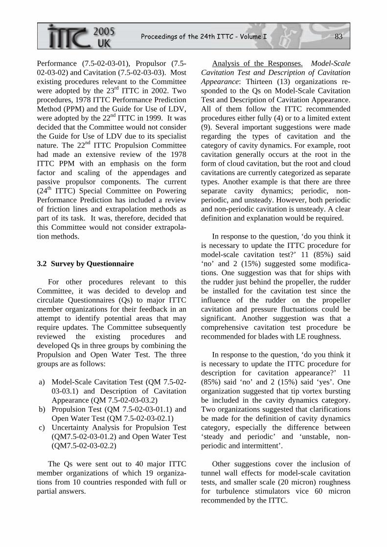
The most promising hybrid concept reported in recent years is the combination of a conventional single propeller and a down-stream pulling-type (tractor-type) podded propulsor replacing the rudder, operating as a contra-rotating unit, known as CR-Pod (see Fig. 3.1). These hybrid arrangements can still develop the high efficiency of CRP while maintaining a centreline single shaft arrange-ment. Application areas include fast ferries (Praefke et al., 2001) and large container vessels (Kim et al., 2002, Go et al., 2003, Holtrop and Valkhof, 2003). Model tests at MARIN showed 5 to 10% increase in propul-sive efficiency compared to a single propeller concept (Holtrop and Valkhof, 2003). Two high-speed Ro-Pax ferries with the same arrangement of a podded propulsor behind a conventional propeller were constructed at
Proceedings of the 24th ITTC - Volume I 85
MHI and launched in 2004 (Ohshima and Hoshino, 2005). MARIN also tested twin pods on each side of the centreline propeller. In this case, however, the required power was more than that with a single propeller. A combina-tion of conventional propellers and waterjets was also explored for a corvette (Wessel, 2004).
Figure 3.1- Hybrid CR-Pod concept.
Model testing and full-scale performance prediction for podded propulsors and waterjets are difficult in itself, and test procedures and prediction methods are currently being studied by the current 24th ITTC Specialist Committees on Azimuthing Podded Propulsion and on Validation of Waterjet Test Procedures, respec-tively. The testing and full-scale performance predictions are even more complex and difficult for hybrid propulsors.
Model test procedures for a hybrid pod and conventional propellers as a CR unit were presented by Go et al. (2003) and Bushbovsky et al. (2004). In Go’s procedure, the desired power ratio is determined a priori between the main propeller (open propeller) and the podded propeller and self-propulsion tests are carried out at design speed with different rpm ratios from which the rpm ratio that produces the pre-determined power ratio is obtained by inter-polation. With this fixed rpm ratio, self-propulsion tests are performed over a range of ship speeds. Open-water tests were carried out with the upstream propeller and the down-stream pod as a unit. Unlike the conventional open water test where the propeller is operating
in a uniform inflow, the podded CR unit is located downstream of the open-water boat, thus a correction was applied to account for the effect of the wake of the open-water boat. As expected, the influence of pod on the main propeller performance was minimal, but the influence of the main propeller on the downstream podded propeller was significant because the podded propeller is in the slipstream of the main propeller where flow is accelerated. It was also found that the power ratio was changing as a function of advance coefficient with a given rpm ratio.
Go et al. (2003) presented two different methods of predicting full-scale powering performance based on the model test described above. Scale effects on the pod operating downstream of the conventional propeller would be important as pointed out by Holtrop and Valkhof (2003). In one method, Go et al. (2003) used the thrust and torque of the total unit, KT=(Tmain+Tpod)/(ρnmain
2Dmain4) and
KQ=(Qmain+Qpod)/(ρnmain2Dmain
5), where Tpod and Qpod are the net thrust and torque of the pod accounting for the drag of the pod and the strut. They, then, followed the ITTC 1978 method in a straight forward manner. In this method, the propeller-hull interaction, that is the wake fraction and thrust deduction, of each compo-nent is not properly accounted for. In the second method, the main propeller and the podded propeller are treated separately to obtain the individual power and rpm. For the main propeller, the ITTC 1978 method was used with a modified thrust deduction factor, t, in such a way that the sum of the ts for the main propeller and the pod will be the same as the t for the first method. For the pod, the wake scaling cannot follow the ITTC 1978 procedure since the pod is operating in an accelerated flow region in the slipstream of the main propeller. Go et al. (2003) proposed a correc-tion method for the pod. Since the wake fraction of the full-scale main propeller will be smaller than the model scale value, the effec-tive J for full scale is larger than the model scale J. The delivered power (PD) by the podded propeller will then be computed by the
86 The Propulsion Committee
PD of the main propeller multiplied by the new power ratio at the shifted J value, and the rpm of the podded propeller will be computed by the rpm at the pre-determined power ratio multiplied by the 1/3 power of the change in power due to the shift in J. It turned out, however, that the final total PD is almost the same between the two methods.
Despite such efforts by Go et al. (2003) and by other towing tanks to develop new proce-dures and prediction methods, there are no standard test procedures and full-scale perform-ance prediction methods currently available for these hybrid propulsors, nor are there any attempts to develop such standard procedures and methods. In order to take full potential advantages of these hybrid propulsor concepts, improved test procedures and powering predic-tion methods must be developed. Systematic powering tests in the towing tank will be needed, together with computations using relevant CFD codes.
3.4 Benchmark Data
Since benchmark data should be accurate, reliable, and well documented, sophisticated instruments and skilled experimentalists are required to acquire such data. Several recent papers and reports present archival quality data that could be used as benchmark data.
DTMB has recently conducted experiments using LDV and PIV in its 36-inch variable-pressure water tunnel to measure in detail the tip-gap flow of a ducted propulsor (Chesnakas and Jessup, 2003). In this experiment, the evolution of the leakage vortex in the gap of the blade tip and the duct inner surface and its unsteady interaction with the blade tip vortex has accurately been measured. The interaction between the leakage vortex and the tip vortex is known to be responsible for cavitation incep-tion. Such complex flow has never been measured before.
Another set of experiments was made at DTMB to characterize the unsteady separated flow around a conventional open propeller in crash-back conditions (Jessup et al., 2004). Crash-back is defined by a condition where the ship is moving forward and the propeller is operating in a negative direction. In this experi-ment, highly unsteady separated flow around a propeller in crash-back modes has been meas-ured, together with shaft forces and moments. A large ring vortex surrounding the propeller was observed that is a typical flow phenome-non for the crash-back condition.
Researchers at INSEAN, Italy have con-ducted Stereo-PIV (SPIV) measurements of flow downstream of a propeller working behind a ship model (Series 60) in their free-surface circulating water channel (Felli et al., 2002). The SPIV technique allows measure-ments of 3-D flows to be done much faster than with LDV techniques. Three velocity compo-nents and turbulence intensity were measured at three downstream stations with propeller rotating. Evolution of propeller wake as it is moving downstream was characterized.
Another set of benchmark data are model and full-scale surface pressure measurements on two propellers of Seiun Maru ship by researchers at NMRI, Japan. Although the ex-periments were conducted many years ago and several papers were already published (Ukon et al., 1990a, 1990b, 1991a, 1991b, 1992), the full-scale data are still extremely valuable for code validation.
Measurements of such unsteady flow are extremely difficult and time-consuming. These data would be valuable for validation of CFD codes. An effort is underway to put these experimental data, together with the geometries of the propellers and the hull on the website for easy access by the potential users.
Proceedings of the 24th ITTC - Volume I 87
4. DEVELOP AN ITTC PROCEDURE FOR SPECIFYING THE ACCURACY OF MODEL PROPELLER GEOMETRY REQUIRED FOR PROPULSION AND CAVITATION TESTING
4.1 Background
One task for this Committee is to ‘Develop an ITTC procedure for specifying the accuracy of model propeller geometry required for propulsion and cavitation testing’.
The Report of the 23rd ITTC Propulsion Committee gave comments on and discussed the problems of the accuracy of model propel-ler geometry. Cavitation testing of model propellers, in particular, requires special atten-tion to the propeller geometry. The accuracy of the blade edges is important to ensure proper simulation of the full-scale cavitation behav-iour of the propeller. The ITTC procedure 7.5-01-01-01 ‘Ship Models’ contains manufactur-ing tolerances for propeller models used for propulsion and open water tests. The new procedure has been developed especially for model propellers used for cavitation tests.
4.2 Tolerances
The new procedure contains recommenda-tions for the manufacturing tolerances of diameter, pitch, chord length, blade section offsets, rake, location of blades and blade surface finish.
The sources for the recommended manufac-turing tolerances include the ISO standards 484/1 and 484/2, quality standards for model propellers at different model basins and the results of systematic calculations to study the influence of propeller parameters on the propeller characteristics.
The open water characteristics of the propeller are mainly influenced by the accuracy
of the global parameters, such as diameter, pitch, camber, chord length and thickness of the propeller blades. The maximum differences in the thrust and torque coefficients, KT, KQ due to manufacturing inaccuracies of the model propeller and measurement deviations should be smaller than ±1%. Potential flow calcula-tions for a fixed pitch propeller with a simple geometry (see Table 4.1) have been carried out to study the influence of defined, systematic deviations in the propeller geometry on the open water characteristics. Attempts at using CFD to quantify the effects of errors in leading edge geometry on pressure characteristics and cavitation inception were not successful.
Table 4.1- Propeller main data.
Diameter D = 240 mm Pitch ratio P0.7/D = 0.935 Expanded area ratio AE/A0 = 0.532 Hub ratio dh/D = 0.23 Rake ε = 8° Number of blades Z = 4 Profile type NACA 16, a = 0.8
r/R c [mm] t [mm] P/D f/c 0.3 53.4 9.88 0.963 0.0189 0.5 64.3 6.50 0.946 0.0218 0.7 75.1 4.28 0.935 0.0163 0.9 69.8 2.23 0.943 0.0132
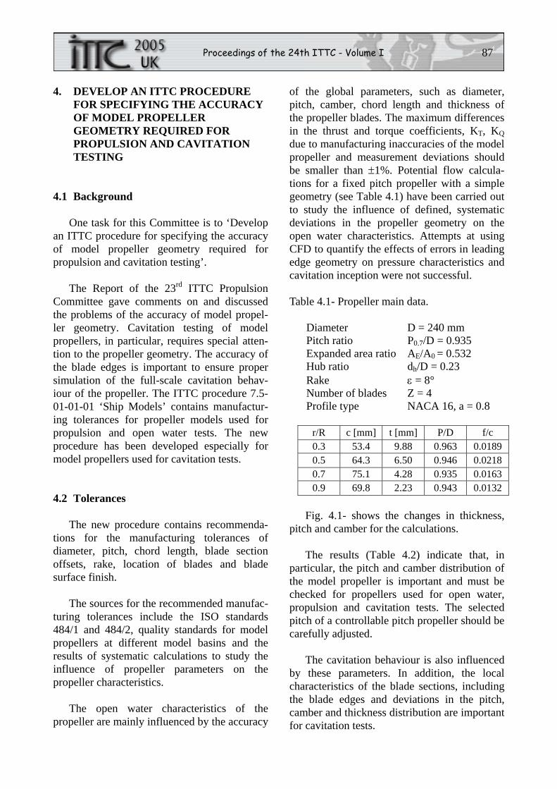
Fig. 4.1- shows the changes in thickness, pitch and camber for the calculations.
The results (Table 4.2) indicate that, in particular, the pitch and camber distribution of the model propeller is important and must be checked for propellers used for open water, propulsion and cavitation tests. The selected pitch of a controllable pitch propeller should be carefully adjusted.
The cavitation behaviour is also influenced by these parameters. In addition, the local characteristics of the blade sections, including the blade edges and deviations in the pitch, camber and thickness distribution are important for cavitation tests.
88 The Propulsion Committee
Figure 4.1- Description of the variations in pro-peller geometry.
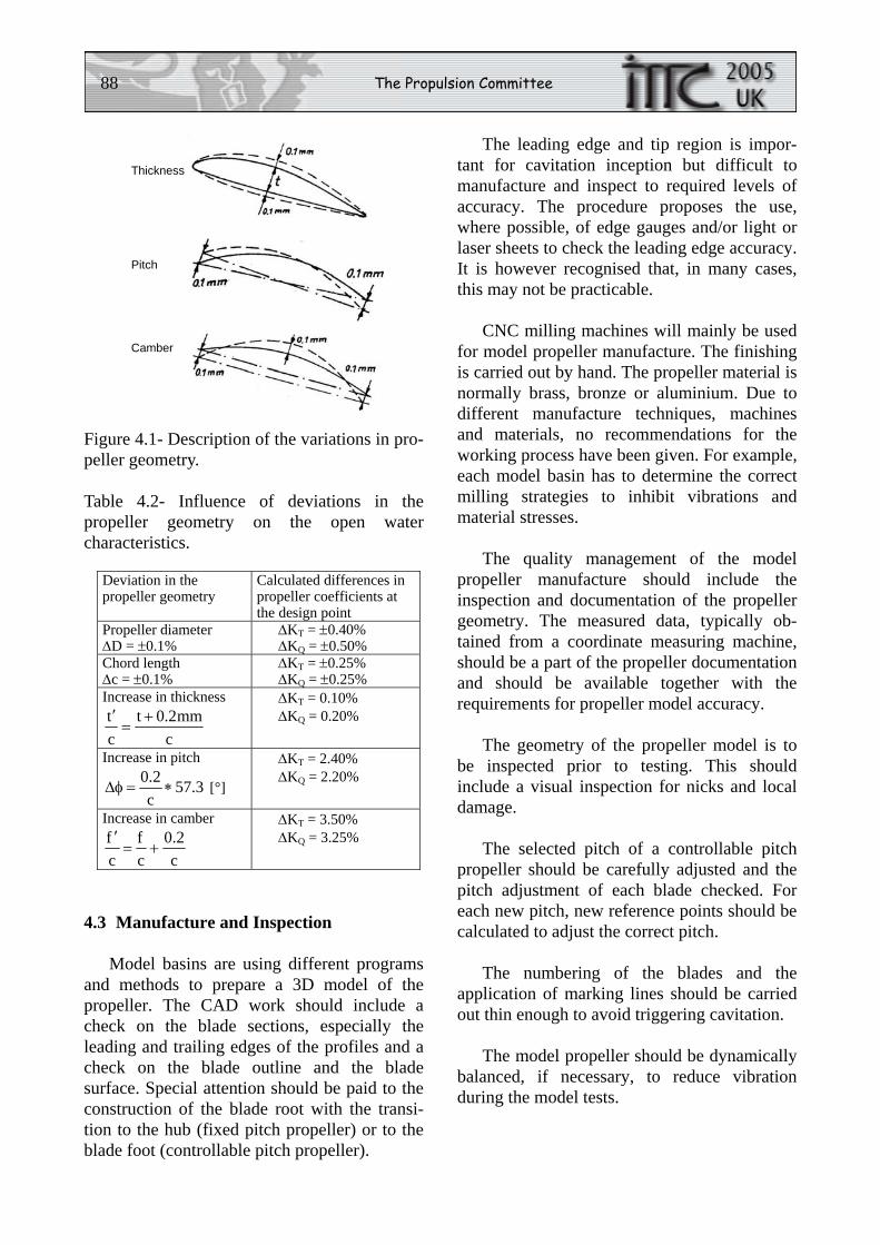
Table 4.2- Influence of deviations in the propeller geometry on the open water characteristics.
Deviation in the propeller geometry
Calculated differences in propeller coefficients at the design point
Propeller diameter ΔD = ±0.1%
ΔKT = ±0.40% ΔKQ = ±0.50%
Chord length Δc = ±0.1%
ΔKT = ±0.25% ΔKQ = ±0.25%
Increase in thickness
cmm2.0t
ct +=
′
ΔKT = 0.10% ΔKQ = 0.20%
Increase in pitch
3.57c2.0∗=φΔ [°]
ΔKT = 2.40% ΔKQ = 2.20%
Increase in camber
c2.0
cf
cf
+=′
ΔKT = 3.50% ΔKQ = 3.25%
4.3 Manufacture and Inspection
Model basins are using different programs and methods to prepare a 3D model of the propeller. The CAD work should include a check on the blade sections, especially the leading and trailing edges of the profiles and a check on the blade outline and the blade surface. Special attention should be paid to the construction of the blade root with the transi-tion to the hub (fixed pitch propeller) or to the blade foot (controllable pitch propeller).
The leading edge and tip region is impor-tant for cavitation inception but difficult to manufacture and inspect to required levels of accuracy. The procedure proposes the use, where possible, of edge gauges and/or light or laser sheets to check the leading edge accuracy. It is however recognised that, in many cases, this may not be practicable.
CNC milling machines will mainly be used for model propeller manufacture. The finishing is carried out by hand. The propeller material is normally brass, bronze or aluminium. Due to different manufacture techniques, machines and materials, no recommendations for the working process have been given. For example, each model basin has to determine the correct milling strategies to inhibit vibrations and material stresses.
The quality management of the model propeller manufacture should include the inspection and documentation of the propeller geometry. The measured data, typically ob-tained from a coordinate measuring machine, should be a part of the propeller documentation and should be available together with the requirements for propeller model accuracy.
The geometry of the propeller model is to be inspected prior to testing. This should include a visual inspection for nicks and local damage.
The selected pitch of a controllable pitch propeller should be carefully adjusted and the pitch adjustment of each blade checked. For each new pitch, new reference points should be calculated to adjust the correct pitch.
The numbering of the blades and the application of marking lines should be carried out thin enough to avoid triggering cavitation.
The model propeller should be dynamically balanced, if necessary, to reduce vibration during the model tests.
Thickness
Pitch
Camber
Proceedings of the 24th ITTC - Volume I 89
Model basins often use the same propeller for open water, propulsion and cavitation tests for the ship using the final propeller design. In this case, it is recommended that the propeller model should always be manufactured with accuracy according to the manufacturing toler-ances of the propeller model for cavitation tests.
The full recommended procedure for Model Propeller Accuracy is included in the ITTC Quality Manual as Procedure 7.5-01-02-02.
5. REVIEW THE DEVELOPMENT OF NUMERICAL DESIGN AND ANALYSIS METHODS FOR PROPULSORS
5.1 Introduction
There is a continuous trend of increased use of theoretical and computational tools to address marine propulsion hydrodynamics. Improvements in theoretical models allow the investigation of conventional and unconven-tional propellers in realistic working conditions. Also, sophisticated computational codes are becoming popular as design and optimization tools.
Recent developments in propulsor flow simulation and their impact on design are reviewed. The emphasis is on the work per-formed during the last few years, as an update of similar reviews reported in the past ITTC Propulsion Committee Reports. The review is made for theoretical and computational methods of inviscid and viscous flows, and integrated viscous/inviscid methods. The im-pact of numerical hydrodynamic tools in design applications is also discussed.
5.2 Theoretical and Computational Methods for Inviscid Flow
After decades of development and exten-sive applications, inviscid-flow methods are
still widely used and are the subject of new research, primarily because they are fast and efficient for preliminary design and analysis. Another, not less important, motivation of the present interest in inviscid-flow methods is related to the development of hybrid computa-tional tools combining inviscid and viscous solvers.
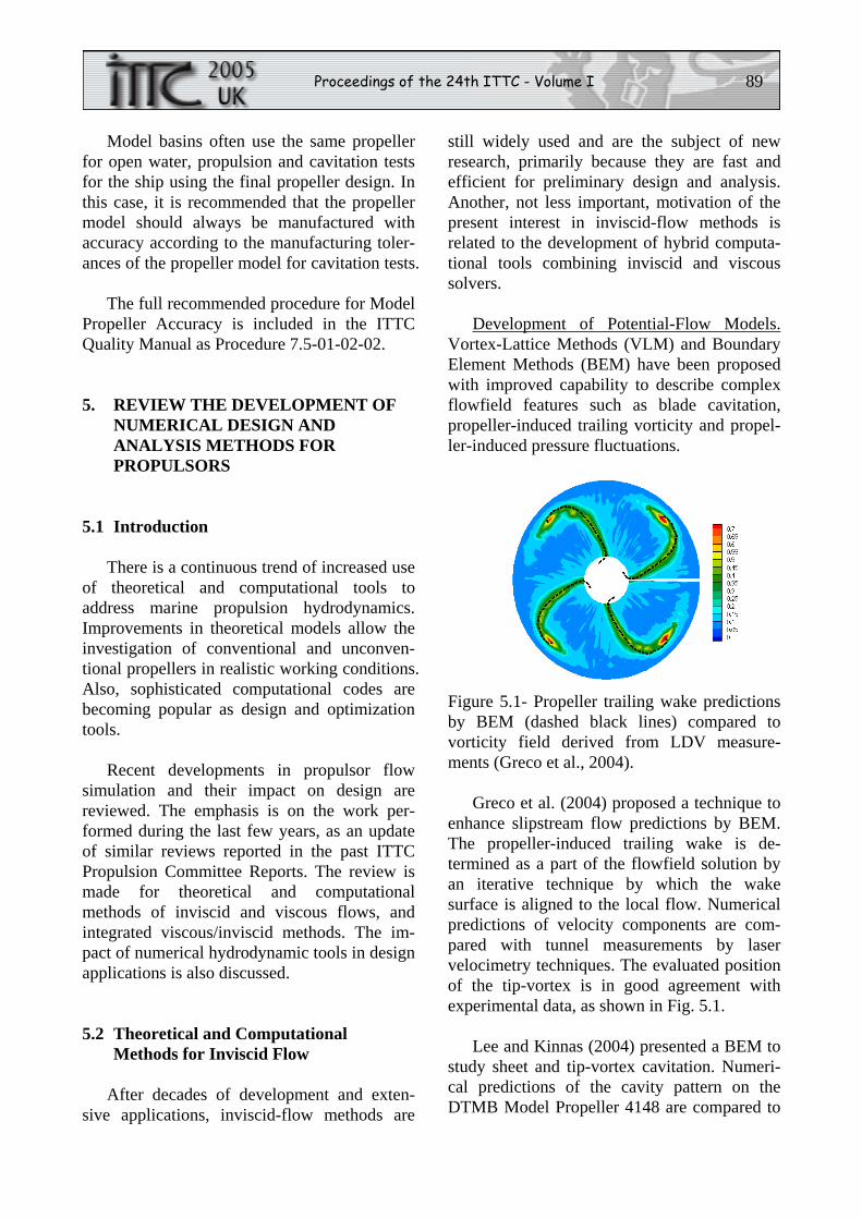
Development of Potential-Flow Models. Vortex-Lattice Methods (VLM) and Boundary Element Methods (BEM) have been proposed with improved capability to describe complex flowfield features such as blade cavitation, propeller-induced trailing vorticity and propel-ler-induced pressure fluctuations.
Figure 5.1- Propeller trailing wake predictions by BEM (dashed black lines) compared to vorticity field derived from LDV measure-ments (Greco et al., 2004).
Greco et al. (2004) proposed a technique to enhance slipstream flow predictions by BEM. The propeller-induced trailing wake is de-termined as a part of the flowfield solution by an iterative technique by which the wake surface is aligned to the local flow. Numerical predictions of velocity components are com-pared with tunnel measurements by laser velocimetry techniques. The evaluated position of the tip-vortex is in good agreement with experimental data, as shown in Fig. 5.1.
Lee and Kinnas (2004) presented a BEM to study sheet and tip-vortex cavitation. Numeri-cal predictions of the cavity pattern on the DTMB Model Propeller 4148 are compared to
90 The Propulsion Committee
visualisations from tunnel tests. The capability to predict attached cavities was demonstrated whereas prediction of the tip-vortex cavitation needs further assessment.
Krasilnikov et al. (2003) presented an invis-cid flow method to study sheet cavitation on podded propellers and on rudders. The approach extends a velocity-based BEM for an isolated propeller proposed by Achinadze and Krasilnikov (2003). The interaction between propeller and rudder is achieved by an iterative approach in which a propeller-flow solution is used to determine a circumferentially-averaged inflow to the rudder. Next, rudder flow is solved and its effect on the propeller is deter-mined. A new propeller flow solution is then evaluated and the procedure is iterated. Numerical prediction of the isolated-propeller induced velocity is in satisfactory agreement with available measurements. Rudder forces are accurately predicted at low rudder angles, where viscosity effects are negligible. Pre-dicted sheet cavity area on the rudder surface is in qualitative agreement with tunnel measure-ments.
A higher-order BEM formulation based on B-spline representations for both geometry and velocity potential was proposed by Lee et al. (2004). Computations of steady flow in the tip region showed a significant improvement compared to predictions by conventional low-order potential flow methods.
Hybrid Viscous/Inviscid Flow Models. Hy-brid models have been developed to combine the advantages of both inviscid and viscous-flow models into efficient (i.e., accurate and fast) numerical prediction tools. In a typical hybrid scheme, an iterative method is used where the propulsor inflow is computed by a viscous flow solver with the propeller effect represented by a body force model (Schetz and Favin, 1977, Stern et al., 1988).
Recent applications include propeller/ rudder configurations, podded propulsors, and combined conventional/podded propulsors.
Viscous flow solvers are typically based on RANS. Inviscid flow solvers may be either based on lifting-surface methods (Black and Michael, 2003), VLM (Lee and Chen, 2003), or BEM (Hsin et al., 2002). Kinnas et al. (2004) presented a combined Euler/VLM approach to study ducted and podded twin propellers.
Alternative to body-force methods, a zonal approach with a velocity-field iteration proce-dure is also used (Deniset et al., 2003a, 2003b, Laurens and Cordier, 2003). The propeller flow is solved by BEM and the propeller-induced velocity field is evaluated within a disk located just behind the propeller. This velocity field is used as the inlet boundary condition for an unsteady RANS simulation of the flow around strut and pod. Preliminary results showed the capability of the proposed methodology to determine pressure fluctuations on the pod strut, but comparisons with experimental data were not considered.
An important application of hybrid methods is the evaluation of the effective wake. Both Euler/potential-flow and RANS/potential-flow approaches have been proposed. Recent devel-opments on this subject include Choi and Kinnas (2001, 2003), Hsin et al. (2002), Luebke (2003), and Ohashi and Hino (2004). A detailed review of computational methods is given in Section 8 of the present Report.
5.3 Theoretical and Computational Methods for Viscous Flow
Viscous flow methods are becoming a reli-able means of investigating propeller flow details that require physical modelling beyond the capability of inviscid-flow methods. De-pending upon the degree of modelling of the flow physics, RANS, Large Eddy Simulations (LES), Detached Eddy Simulations (DES) and Direct Numerical Simulations (DNS) have been proposed for the analysis of flow around cavitating and non-cavitating propellers. However, the applicability of these methods to
Proceedings of the 24th ITTC - Volume I 91
problems of practical interest is severely limited by the excessive computational efforts required to study even very simple configura-tions (Wilkstrom et al., 2003, and Kunz et al., 2003).
Among these CFD approaches, RANS methods are most appealing for marine propul-sor flows primarily because the computational time is reasonable compared to LES and DNS. DES is also becoming increasingly used by taking advantage of both RANS and LES aspects. Although many R&D organizations and universities have been developing and maintaining their own codes, commercial codes are becoming popular in the shipyards and R&D organizations. Most current approaches have common basic features, including finite volume approximation and multi-grid accelera-tion. Different strategies are used for grid topology, turbulence modelling and cavitating-flow modelling.
Abdel-Maksoud et al. (2004) analysed the effect of the hub cap shape on propeller performance using the commercial RANS code, CFX-TASCflow that is a finite-volume, block-structured RANS solver. Computations are per-formed for a 5-bladed CPP with three different hub-cap shapes at model- and full-scale. The computed slipstream flow is qualitatively con-firmed by experimental measurements using LDV and PIV methods. Discrepancies between predicted and measured propeller efficiency are attributed to the insufficient grid resolution at outer radii. The calculated full-scale pressure coefficients show a strong reduction in the hub vortex region compared to the model scale. The authors concluded that the hub vortex cavita-tion may require a scaling law similar to those used for tip vortex cavitation (McCormic, 1962).
The same software is utilized to investigate scale effects on a ducted propeller by Abdel-Maksoud and Heinke (2002). The gap between the blade tip and the duct is taken into account. Numerical results of the Wageningen 19A nozzle with KA5-75 propeller at model and full
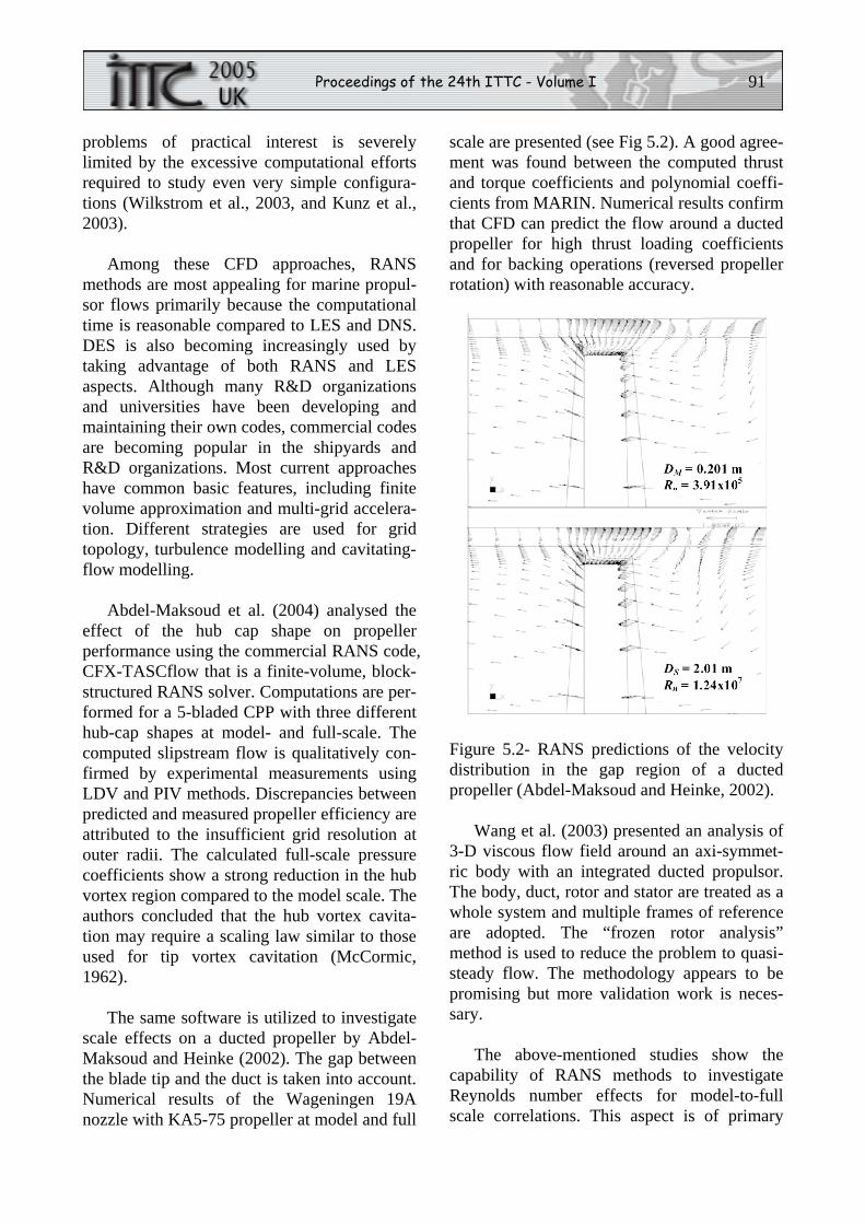
scale are presented (see Fig 5.2). A good agree-ment was found between the computed thrust and torque coefficients and polynomial coeffi-cients from MARIN. Numerical results confirm that CFD can predict the flow around a ducted propeller for high thrust loading coefficients and for backing operations (reversed propeller rotation) with reasonable accuracy.
Figure 5.2- RANS predictions of the velocity distribution in the gap region of a ducted propeller (Abdel-Maksoud and Heinke, 2002).
Wang et al. (2003) presented an analysis of 3-D viscous flow field around an axi-symmet-ric body with an integrated ducted propulsor. The body, duct, rotor and stator are treated as a whole system and multiple frames of reference are adopted. The “frozen rotor analysis” method is used to reduce the problem to quasi-steady flow. The methodology appears to be promising but more validation work is neces-sary.
The above-mentioned studies show the capability of RANS methods to investigate Reynolds number effects for model-to-full scale correlations. This aspect is of primary
92 The Propulsion Committee
importance in the study of unconventional propulsors where classical extrapolation tech-niques for conventional propellers are not applicable, and CFD can play a unique role.
The use of CFD codes to assess scaling methodologies for unconventional propulsors is addressed by Sanchez-Caja and Ory (2003) and Chicherin et al. (2004). They present RANS calculations of the flow around a tractor-type podded thruster using the software FINFLO, a multi-block, cell-centred finite volume code. The sliding mesh technique is used to match grid blocks around rotating and fixed compo-nents. To reduce the CPU time, the flow is circumferentially averaged through the sliding surface located between the propeller and the strut to enforce steady-state calculations. Hydrodynamic loads, blade pressure distribu-tions and flow velocity are studied both at model and full scales. Chicherin et al. (2004) concluded that scaling rules frequently applied to conventional appendage drag should not be used for the pod housing, as numerical predic-tions show that the form factor depends on both Reynolds number and propeller loading.
Computational Grid Topology. Gridding is a major source of difficulty in CFD analysis of marine propellers. The flowfield around a propeller is typically delimited by the complex geometry, and a smooth distribution of grid cells could be very difficult. Important flow-field structures such as the shaft and bracket wake as well as blade tip-vortices require local grid refinements. Moreover, propulsion test simulations are characterized by very different spatial and time scales for the hull and propel-ler flows. Inaccuracy of the predicted flowfield is frequently attributed to inadequate discretiza-tion of the computational domain.
Using structured curvilinear grids can result in an excessive number of cells being required and very complicated and time consuming grid generation procedures. As an alternative, unstructured grids are becoming very popular because of relative easiness of handling complex geometries and of clustering grid cells
in flow regions where large gradients of flow quantities occur. Automated grid generation is possible.
Rhee and Joshi (2003) present computa-tions of the marine propeller flow using the commercial RANS code, FLUENT with a k-ω turbulence model. Hybrid unstructured meshes are used where prismatic cells are built in the boundary layer, and tetrahedral cells fill the computational domain far from solid bounda-ries. This allows a highly accurate description of the boundary layer flow while retaining most of the advantages of unstructured grid-ding. They analysed the five-bladed CPP 5168 in open water conditions. The predicted thrust and torque coefficients are within 8% and 11%, respectively, of the experimental measurements. The circumferential averaged velocities and turbulent quantities behind propeller are also compared with the experiments. A good agree-ment is found for axial and tangential velocity components, but the predicted radial velocity component was less accurate. Turbulent veloc-ity fluctuations in the wake region are partly under-predicted due to excessive numerical dissipation.
A promising approach to improve grid generation for complex geometry is the Chimera technique. The basic idea is to deter-mine the computational grid by composing simple structured sub-grids that fill limited portions of the fluid domain ('child' grids). Sub-grids may overlap and all of them are embedded into a grid (called the 'mother' or 'background' grid) that extends to the whole fluid domain. For ship viscous-flow simula-tions, Chimera techniques are becoming popu-lar (Muscari and Di Mascio, 2005), and few early attempts to address tip-vortex and propel-ler flows have recently been presented (Hsiao and Chahine, 2001, Kim et al., 2003).
Research is still necessary to achieve robust and reliable modelling of boundary layers and wakes, turbulence and two-phase flow features. Several turbulence models are available for users to choose for specific applications. Kim

Proceedings of the 24th ITTC - Volume I 93
and Rhee (2004) analysed the tip-vortex flow by using FLUENT with four different turbu-lence models, including eddy-viscosity and Reynolds-stress transport models. The inter-play between turbulence modelling and local mesh refinements is carefully analysed and the importance of adequate grid resolution of flowfield regions where vortical flow dominates is stressed.
5.4 Numerical Design and Optimization Techniques
Recent developments in theoretical model-ling are reflected in the increased range of applicability of computational codes to design propulsion units. Well established inviscid-flow codes as well as viscous flow codes are employed.
Design exercises using potential-flow codes are presented by Wang and Yang (2003) for conventional propellers, and by Viviani et al. (2003) for new blade sections with optimized cavitation bucket. Similarly, Dang (2004) discussed a propeller design procedure based on iterative 2-D profile design and 3-D propel-ler flow verification. Applications to a chemi-cal tanker and to a large container ship are illustrated.
The feasibility of automated design-by-analysis using an enhanced potential-flow method with a simple modelling of viscosity effects is demonstrated by Krasilnikov et al. (2003). They combine a LS method for design and BEM for analysis. Design applications to conventional propellers, propeller/rudder com-binations and CR-Pod propellers were pre-sented. An example of design/analysis proce-dure for a podded propulsor is also presented. The importance of housing effects on the podded propulsor blade shape design is demon-strated.
Ukon et al. (2004a) presented a TCP design using an inviscid-flow code that is similar to the one by Kudo and Ukon (1994) for SCP.
Johnson’s and Eppler’s methods for optimal blade section design and Lerbs’ method for circulation distribution are combined with an improved LS theory to determine the final blade shape.
Bushkovsky et al. (2004) presented a proce-dure to design a conventional propeller and contra-rotating podded propeller propulsion unit. Performance predictions of the two pro-pellers were made by using VLM and BEM with cavitating flow analysis capability. Mutual interactions among propulsor components were taken into account by an iterative approach and suitable modelling of the vortical/viscous wake induced by fore propeller to the aft one was proposed.
The increased availability of high perform-ance computers stimulates attempts to use RANS codes as design tools. The advantage over inviscid methods is the capability to take into account complex vortical/viscous-flow features. The impact of small shape variations on performance can be computed and hence reliable shape optimization is possible and the amount of model testing can be reduced. Addi-tionally, full-scale Reynolds number flows can be studied and hence guidance for extrapola-tion from model to full-scale could be obtained.
Figure 5.3- Predicted vorticity field around a podded propulsor by RANS (Streckwall and Tigges, 2003).
Attempts to use CFD for design have been proposed by Streckwall and Tigges (2003) (see Fig. 5.3) and Streckwall et al. (2004), who pre-sented a design study for a fast ferry through a
94 The Propulsion Committee
complete series of CFD simulations including open water, resistance and propulsion tests. Sanchez-Caja and Pylkkanen (2004) presented a design of a non-symmetrical strut of a pulling pod in order to reduce cavitation risk in the strut leading edge region.
The feasibility of design-by-analysis of complex configurations using viscous-flow simulations was also addressed by Zhang and Wang (2003), and Zhang et al. (2003). Heinke and Heinke (2003) described a combined experimental and numerical study to determine the best arrangement of a pod unit. In particular, the parametric variation of housing diameter to length ratio is performed to determine high-efficiency shapes for fast ship pod drives.
The advantages of automated design are further exploited by numerical optimization techniques. Through a sensitivity analysis, the effect of small variations of a given set of parameters on the propeller performance is determined and the optimum configuration meeting practical constraints can be achieved. Multi-objective and multi-disciplinary analyses are appealing for practical applications.
Applications to marine propellers include both preliminary definition of the optimal propulsor characteristics and shape optimiza-tion of propulsor parts. Parametric optimization to determine the basic characteristics of a podded propeller for cargo and ferry vessels was presented by Goubault and Perree (2004). Brewer et al. (2003) presented a gradient-based steepest-descent method to determine propeller blades with enhanced performance. Flowfield calculations were performed by the unsteady RANS unstructured code UNCLE. Numerical applications include a conventional propeller, a ducted propeller and a blood pump.
Recent applications also confirm a practical interest in optimization techniques based on Genetic Algorithms (GA) and Neural Network approaches. Simple to be implemented, these methods usually require a very large number of iterations to determine the optimal solution.
Examples were given by Karim (2003) who presented a shape optimization exercise of a lifting body, and by Sverko (2003), where a methodology to determine the optimal propel-ler shaft alignment was described.
6. REVIEW DESIGN AND PERFORMANCE ASPECTS OF SECONDARY THRUSTERS, SUCH AS TUNNEL, AZIMUTHING AND DYNAMIC POSITIONING DEVICES
6.1 Introduction
The Propulsion Committee defined ‘secon-dary thrusters’ as devices, which produce thrust in any horizontal direction to balance the envi-ronmental forces on a ship or an offshore struc-ture for the purpose of station keeping and/or enhanced manoeuvring (berthing, crabbing, rotating, etc.). Typically, bow/stern tunnel thrusters, azimuthing thrusters, azimuthing pod units, Voith-Schneider propellers and pump-jets may be classified under this category. Azimuthing thrusters and pod units are gener-ally considered the primary propulsion system. When they are engaged in station keeping and/or manoeuvring mode of operation, however, they can be considered secondary thrusters.
This Committee initiated an inquiry among major thruster manufacturers about recent design and performance issues. However, re-sponses were very modest, and mostly limited to public marketing materials and brochures, as well as Internet websites. It appeared that industry is generally reluctant to reveal detailed design procedures, as those are considered confidential. Therefore, the Committee decided not to include unpublished information from industry in this Report.
Since design and performance issues for secondary thrusters have not been dealt with by the previous Committees, this Committee reviewed not only recent references but also
Proceedings of the 24th ITTC - Volume I 95
some older ones that are considered to have made significant contributions to the subject area.
6.2 Overview of Tunnel (Jet) Thruster Developments
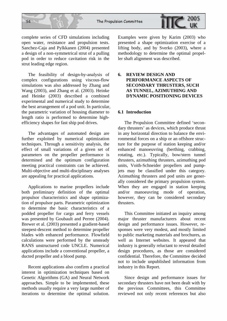
Brix (1993) presented an empirical formula for the turning rate (ψ& ) for ships with tunnel thrusters:
ρψ f
Lk
PP
=&
where, f is thrust/lateral area ratio, PPL is the ship
length between perpendiculars, k is an empiri-cal factor determined by systematic model tests.
Using this relationship and a mean k value of 190° a design diagram was developed, Fig. 6.1. Given a ship type, one can derive neces-sary thruster lateral force and power to meet required rate of turn.
Figure 6.1- Lateral thruster design figure (Brix, 1993).
Tunnel grids are installed for protection of
the jet thruster against mechanical damage and reduction of tunnel resistance at ship forward speed. Ellingsen (1998) concluded that for the most thrusters the thrust loss could be in the range of 5 to 19% depending upon the design and the projected area of the protection grids relative to the tunnel opening.
The rapidly decreasing lateral thruster per-formance at non-zero ship speed is a well-known phenomenon. In general, the thruster transverse force and steering moment decrease by about 50% at a ship speed of 2 knots (Brix, 1993).
Stuntz and Taylor (1964) studied the addi-tional resistance due to thruster tunnel openings with different geometrical characteristics. They calculated an average tunnel drag coefficient of
0.07 (based on tunnel cross-sectional area) and showed by experiments that careful rounding and fairing of the tunnel inlet/outlet could achieve significant reduction in tunnel drag.
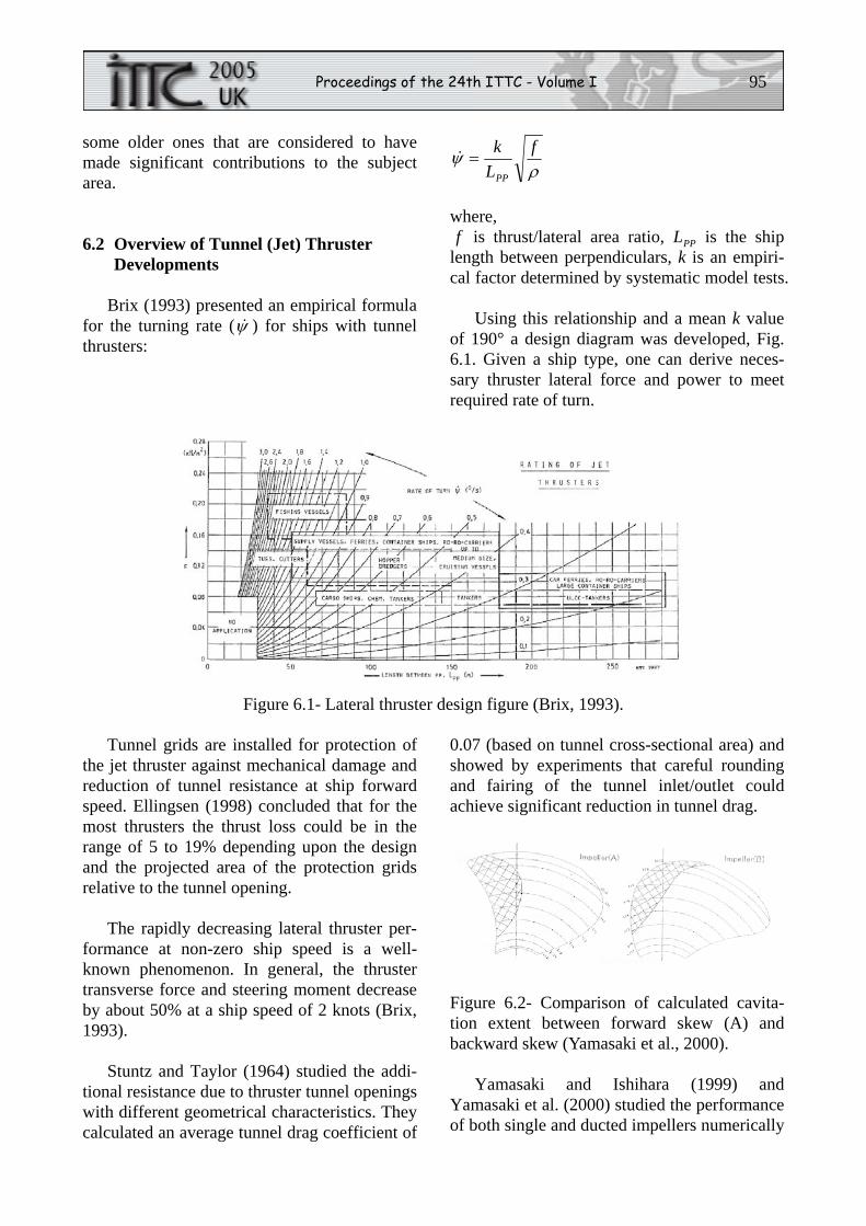
Figure 6.2- Comparison of calculated cavita-tion extent between forward skew (A) and backward skew (Yamasaki et al., 2000).
Yamasaki and Ishihara (1999) and Yamasaki et al. (2000) studied the performance of both single and ducted impellers numerically
96 The Propulsion Committee
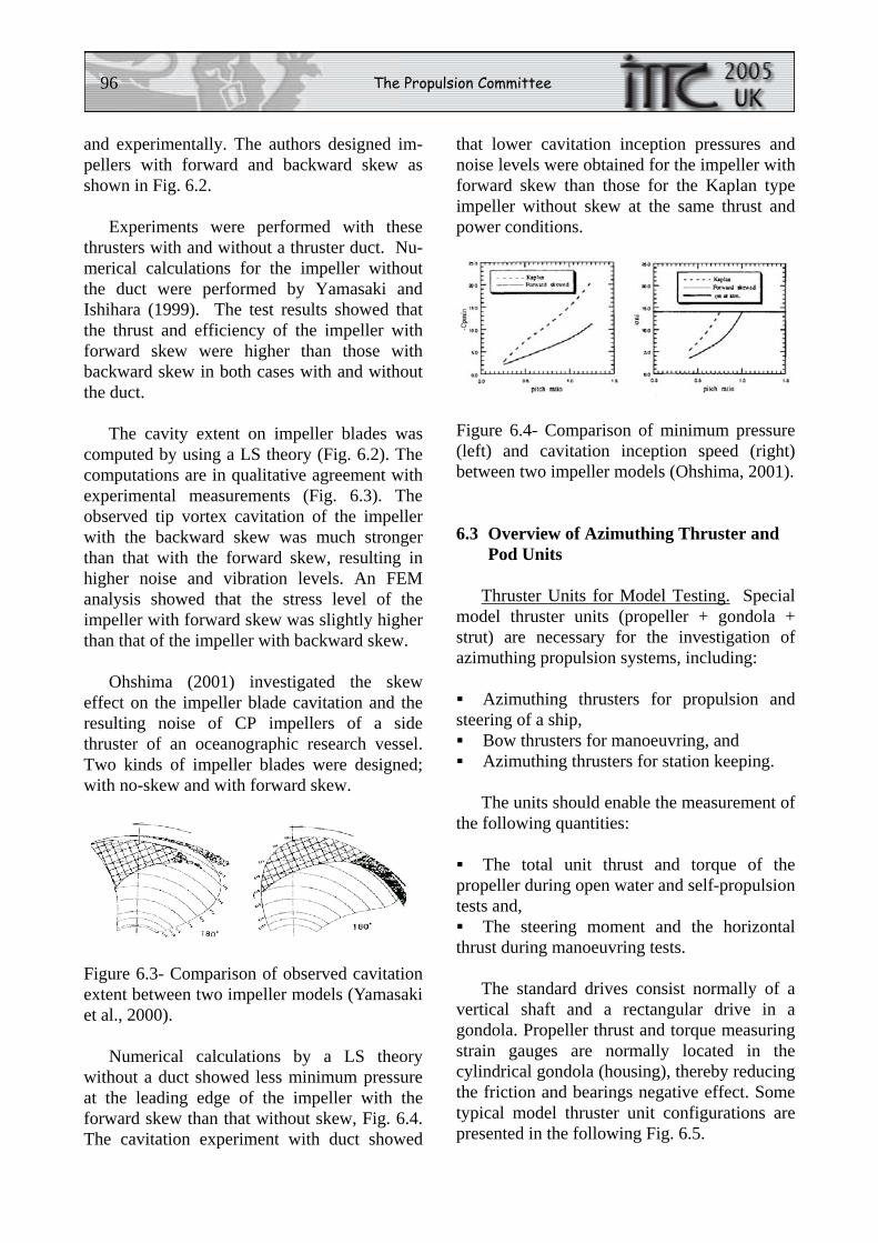
and experimentally. The authors designed im-pellers with forward and backward skew as shown in Fig. 6.2.
Experiments were performed with these thrusters with and without a thruster duct. Nu-merical calculations for the impeller without the duct were performed by Yamasaki and Ishihara (1999). The test results showed that the thrust and efficiency of the impeller with forward skew were higher than those with backward skew in both cases with and without the duct.
The cavity extent on impeller blades was computed by using a LS theory (Fig. 6.2). The computations are in qualitative agreement with experimental measurements (Fig. 6.3). The observed tip vortex cavitation of the impeller with the backward skew was much stronger than that with the forward skew, resulting in higher noise and vibration levels. An FEM analysis showed that the stress level of the impeller with forward skew was slightly higher than that of the impeller with backward skew.
Ohshima (2001) investigated the skew effect on the impeller blade cavitation and the resulting noise of CP impellers of a side thruster of an oceanographic research vessel. Two kinds of impeller blades were designed; with no-skew and with forward skew.
Figure 6.3- Comparison of observed cavitation extent between two impeller models (Yamasaki et al., 2000).
Numerical calculations by a LS theory without a duct showed less minimum pressure at the leading edge of the impeller with the forward skew than that without skew, Fig. 6.4. The cavitation experiment with duct showed
that lower cavitation inception pressures and noise levels were obtained for the impeller with forward skew than those for the Kaplan type impeller without skew at the same thrust and power conditions.
Figure 6.4- Comparison of minimum pressure (left) and cavitation inception speed (right) between two impeller models (Ohshima, 2001).
6.3 Overview of Azimuthing Thruster and Pod Units
Thruster Units for Model Testing. Special model thruster units (propeller + gondola + strut) are necessary for the investigation of azimuthing propulsion systems, including:
Azimuthing thrusters for propulsion and
steering of a ship, Bow thrusters for manoeuvring, and Azimuthing thrusters for station keeping.
The units should enable the measurement of the following quantities:
The total unit thrust and torque of the
propeller during open water and self-propulsion tests and, The steering moment and the horizontal
thrust during manoeuvring tests.
The standard drives consist normally of a vertical shaft and a rectangular drive in a gondola. Propeller thrust and torque measuring strain gauges are normally located in the cylindrical gondola (housing), thereby reducing the friction and bearings negative effect. Some typical model thruster unit configurations are presented in the following Fig. 6.5.
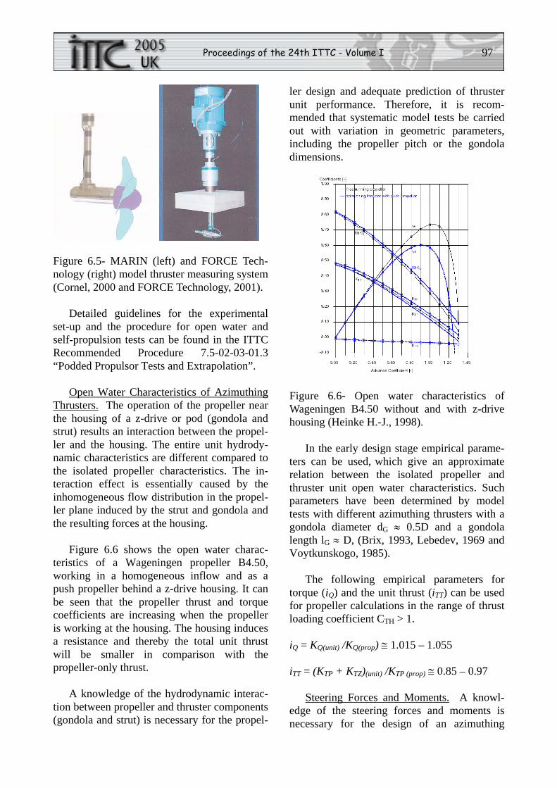
Proceedings of the 24th ITTC - Volume I 97
Figure 6.5- MARIN (left) and FORCE Tech-nology (right) model thruster measuring system (Cornel, 2000 and FORCE Technology, 2001).
Detailed guidelines for the experimental set-up and the procedure for open water and self-propulsion tests can be found in the ITTC Recommended Procedure 7.5-02-03-01.3 “Podded Propulsor Tests and Extrapolation”.
Open Water Characteristics of Azimuthing Thrusters. The operation of the propeller near the housing of a z-drive or pod (gondola and strut) results an interaction between the propel-ler and the housing. The entire unit hydrody-namic characteristics are different compared to the isolated propeller characteristics. The in-teraction effect is essentially caused by the inhomogeneous flow distribution in the propel-ler plane induced by the strut and gondola and the resulting forces at the housing.
Figure 6.6 shows the open water charac-teristics of a Wageningen propeller B4.50, working in a homogeneous inflow and as a push propeller behind a z-drive housing. It can be seen that the propeller thrust and torque coefficients are increasing when the propeller is working at the housing. The housing induces a resistance and thereby the total unit thrust will be smaller in comparison with the propeller-only thrust.
A knowledge of the hydrodynamic interac-tion between propeller and thruster components (gondola and strut) is necessary for the propel-
ler design and adequate prediction of thruster unit performance. Therefore, it is recom-mended that systematic model tests be carried out with variation in geometric parameters, including the propeller pitch or the gondola dimensions.
Figure 6.6- Open water characteristics of Wageningen B4.50 without and with z-drive housing (Heinke H.-J., 1998).
In the early design stage empirical parame-ters can be used, which give an approximate relation between the isolated propeller and thruster unit open water characteristics. Such parameters have been determined by model tests with different azimuthing thrusters with a gondola diameter dG ≈ 0.5D and a gondola length lG ≈ D, (Brix, 1993, Lebedev, 1969 and Voytkunskogo, 1985).
The following empirical parameters for torque (iQ) and the unit thrust (iTT) can be used for propeller calculations in the range of thrust loading coefficient CTH > 1.
iQ = KQ(unit) /KQ(prop) ≅ 1.015 – 1.055
iTT = (KTP + KTZ)(unit) /KTP (prop) ≅ 0.85 – 0.97
Steering Forces and Moments. A knowl-edge of the steering forces and moments is necessary for the design of an azimuthing
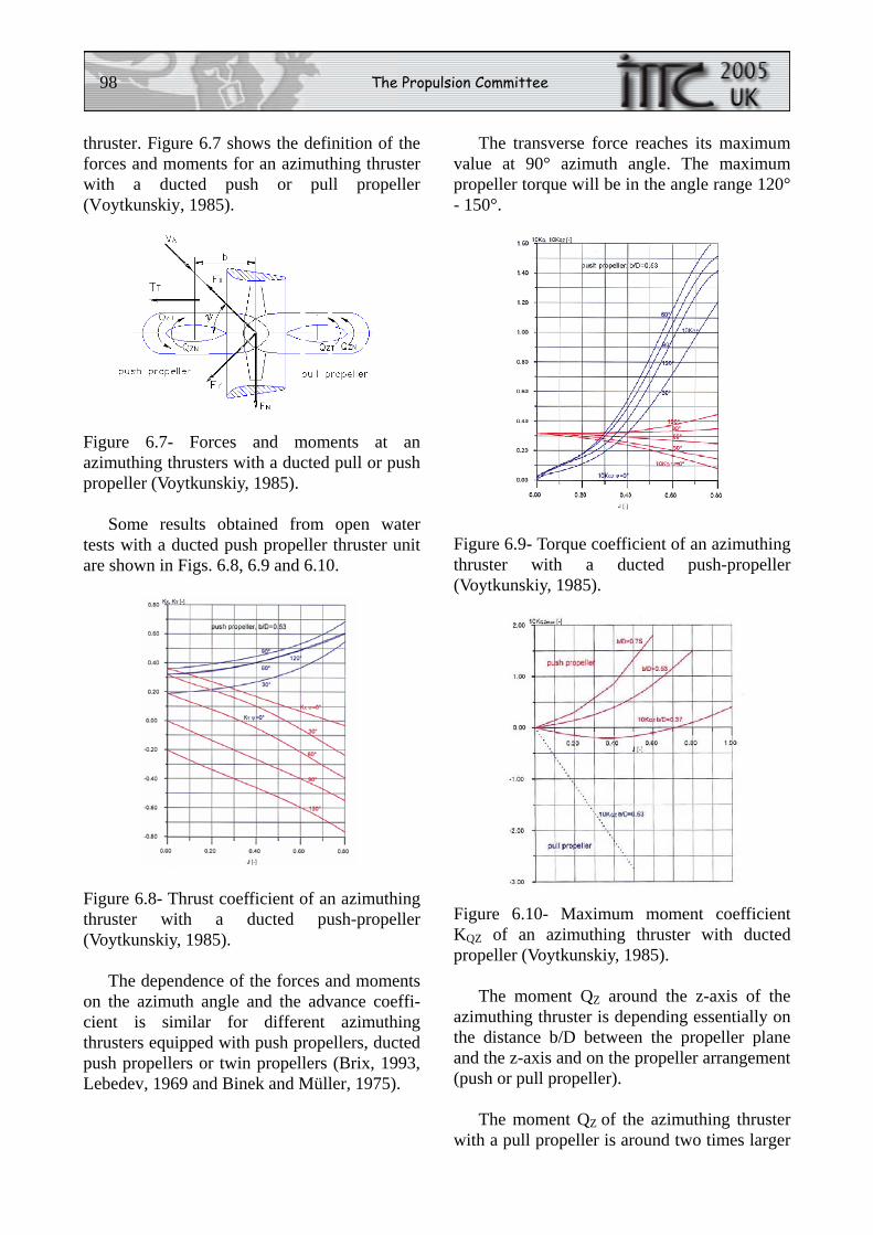
98 The Propulsion Committee
thruster. Figure 6.7 shows the definition of the forces and moments for an azimuthing thruster with a ducted push or pull propeller (Voytkunskiy, 1985).
Figure 6.7- Forces and moments at an azimuthing thrusters with a ducted pull or push propeller (Voytkunskiy, 1985).
Some results obtained from open water tests with a ducted push propeller thruster unit are shown in Figs. 6.8, 6.9 and 6.10.
Figure 6.8- Thrust coefficient of an azimuthing thruster with a ducted push-propeller (Voytkunskiy, 1985).
The dependence of the forces and moments on the azimuth angle and the advance coeffi-cient is similar for different azimuthing thrusters equipped with push propellers, ducted push propellers or twin propellers (Brix, 1993, Lebedev, 1969 and Binek and Müller, 1975).
The transverse force reaches its maximum value at 90° azimuth angle. The maximum propeller torque will be in the angle range 120° - 150°.
Figure 6.9- Torque coefficient of an azimuthing thruster with a ducted push-propeller (Voytkunskiy, 1985).
Figure 6.10- Maximum moment coefficient KQZ of an azimuthing thruster with ducted propeller (Voytkunskiy, 1985).
The moment QZ around the z-axis of the azimuthing thruster is depending essentially on the distance b/D between the propeller plane and the z-axis and on the propeller arrangement (push or pull propeller).
The moment QZ of the azimuthing thruster with a pull propeller is around two times larger
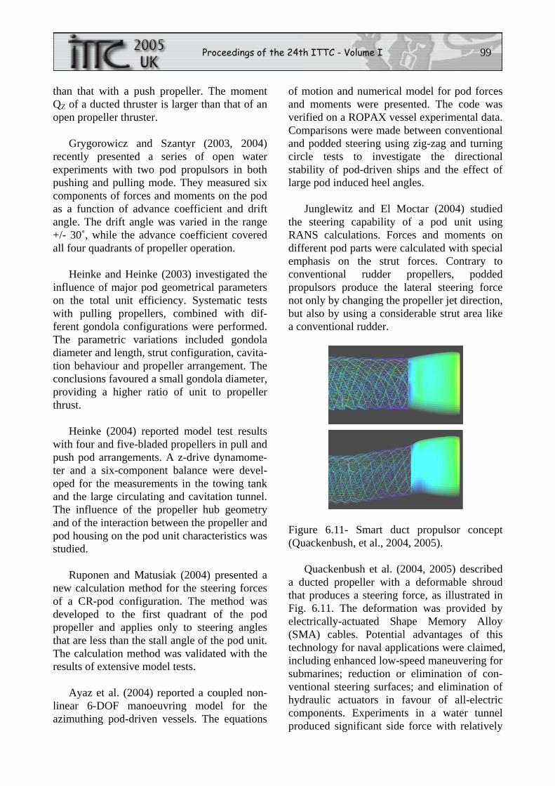
Proceedings of the 24th ITTC - Volume I 99
than that with a push propeller. The moment QZ of a ducted thruster is larger than that of an open propeller thruster.
Grygorowicz and Szantyr (2003, 2004) recently presented a series of open water experiments with two pod propulsors in both pushing and pulling mode. They measured six components of forces and moments on the pod as a function of advance coefficient and drift angle. The drift angle was varied in the range +/- 30˚, while the advance coefficient covered all four quadrants of propeller operation.
Heinke and Heinke (2003) investigated the influence of major pod geometrical parameters on the total unit efficiency. Systematic tests with pulling propellers, combined with dif-ferent gondola configurations were performed. The parametric variations included gondola diameter and length, strut configuration, cavita-tion behaviour and propeller arrangement. The conclusions favoured a small gondola diameter, providing a higher ratio of unit to propeller thrust.
Heinke (2004) reported model test results with four and five-bladed propellers in pull and push pod arrangements. A z-drive dynamome-ter and a six-component balance were devel-oped for the measurements in the towing tank and the large circulating and cavitation tunnel. The influence of the propeller hub geometry and of the interaction between the propeller and pod housing on the pod unit characteristics was studied.
Ruponen and Matusiak (2004) presented a new calculation method for the steering forces of a CR-pod configuration. The method was developed to the first quadrant of the pod propeller and applies only to steering angles that are less than the stall angle of the pod unit. The calculation method was validated with the results of extensive model tests.
Ayaz et al. (2004) reported a coupled non-linear 6-DOF manoeuvring model for the azimuthing pod-driven vessels. The equations
of motion and numerical model for pod forces and moments were presented. The code was verified on a ROPAX vessel experimental data. Comparisons were made between conventional and podded steering using zig-zag and turning circle tests to investigate the directional stability of pod-driven ships and the effect of large pod induced heel angles.
Junglewitz and El Moctar (2004) studied the steering capability of a pod unit using RANS calculations. Forces and moments on different pod parts were calculated with special emphasis on the strut forces. Contrary to conventional rudder propellers, podded propulsors produce the lateral steering force not only by changing the propeller jet direction, but also by using a considerable strut area like a conventional rudder.
Figure 6.11- Smart duct propulsor concept (Quackenbush, et al., 2004, 2005).
Quackenbush et al. (2004, 2005) described a ducted propeller with a deformable shroud that produces a steering force, as illustrated in Fig. 6.11. The deformation was provided by electrically-actuated Shape Memory Alloy (SMA) cables. Potential advantages of this technology for naval applications were claimed, including enhanced low-speed maneuvering for submarines; reduction or elimination of con-ventional steering surfaces; and elimination of hydraulic actuators in favour of all-electric components. Experiments in a water tunnel produced significant side force with relatively
100 The Propulsion Committee
small change in the angle of duct trailing edge. Measurements and computational results were in good agreement. Major issues with this concept for full scale applications are the difficulties associated with the mechanical complexity and the power required for SMA deflection.
Interaction Effects. A classical series of experimental investigations of thruster–thruster and thruster–hull interaction effects was performed by the Ship Research Institute of Norway (Lehn, 1980, 1981, 1985, 1992). Gen-eral thruster performance curves were derived including cavitation for both pulling and push-ing propellers (Lehn, 1980), which readily can be used for preliminary performance estimates. It was found that thrusters-thruster interaction effect may degrade the net thrust up to 50% when one thruster is operating in the slipstream of the other (Lehn, 1981). The thruster-hull interaction forces were strongly dependent on the geometry of the hull and the position of the thrusters. Propeller slipstream hitting the hull/ skeg was found to be the primary source of thrust degradation.
Kourosh (2004) summarized various effects of ventilation/wave interaction between propul-sors, current velocity and direction, as well as possible procedures to estimate the reduction in available forces. Dynamic thrust and torque fluctuations were discussed, which can vary from 0 to 100% of the mean values during one ventilation cycle. For vessels operating in rough seas, these fluctuations can cause fatigue and failure of mechanical parts. Mean available thrust can also be reduced considerably.
Martinussen (1996) presented experimental investigations of shallow water effects on the thruster performance. Both classical fore-and-aft tunnel thrusters and azimuthing thrusters were studied. The results indicated that the shallow water (water depth to ship draught ratio of 1.1) effect could lead to a thrust loss of 30% for the bow tunnel thruster and 15% for the stern tunnel thruster.
Mattila et al. (2002) reported a study of an azimuthing pod used as a station-keeping device on a semi-submersible offshore platform. The computations gave a better understanding of the interaction between the thruster jet and drilling rig pontoons. Calculations were made for model and full scale. The results gave a clear indication that the scale effects signifi-cantly influence the effective thrust of the pod unit. With scaled model tests the optimum tilt angle of the shaft-line with respect to the pontoons was found. Tilting the pod propeller axis by 7 deg down almost eliminated the propeller slipstream – hull interaction effect.
7. REVIEW DEVELOPMENTS IN PREDICTION AND ASSESSMENT OF PROPULSION ISSUES IN SHALLOW WATER
7.1 Overview
Shallow water operation is typically encountered in coastal waters, harbours, rivers and inland waterways. Shallow and restricted water depth will normally lead to restricted design and operational draughts. Extensive research into squat, wave resistance and the generation of wash waves in shallow water has been carried out in recent years. However, published information on estimating the effects of shallow water on propulsion is very limited.
7.2 Propulsion in Shallow Water
Resistance and Propulsion in Shallow Water. The restricted design and operational draughts resulting from shallow water opera-tion tend to limit the maximum propeller diameter leading to high propeller thrust loadings and limited achievable propeller efficiencies. Changes will occur in effective wake and thrust deduction, in propeller/hull interaction and hull efficiency. If critical condi-tions are approached, when ghv= , signifi-cant increases in ship resistance will occur with
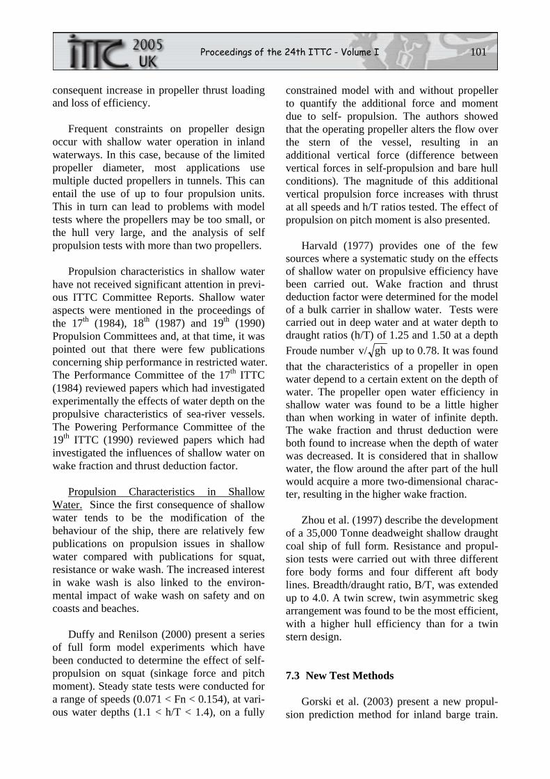
Proceedings of the 24th ITTC - Volume I 101
consequent increase in propeller thrust loading and loss of efficiency.
Frequent constraints on propeller design occur with shallow water operation in inland waterways. In this case, because of the limited propeller diameter, most applications use multiple ducted propellers in tunnels. This can entail the use of up to four propulsion units. This in turn can lead to problems with model tests where the propellers may be too small, or the hull very large, and the analysis of self propulsion tests with more than two propellers.
Propulsion characteristics in shallow water have not received significant attention in previ-ous ITTC Committee Reports. Shallow water aspects were mentioned in the proceedings of the 17th (1984), 18th (1987) and 19th (1990) Propulsion Committees and, at that time, it was pointed out that there were few publications concerning ship performance in restricted water. The Performance Committee of the 17th ITTC (1984) reviewed papers which had investigated experimentally the effects of water depth on the propulsive characteristics of sea-river vessels. The Powering Performance Committee of the 19th ITTC (1990) reviewed papers which had investigated the influences of shallow water on wake fraction and thrust deduction factor.
Propulsion Characteristics in Shallow Water. Since the first consequence of shallow water tends to be the modification of the behaviour of the ship, there are relatively few publications on propulsion issues in shallow water compared with publications for squat, resistance or wake wash. The increased interest in wake wash is also linked to the environ-mental impact of wake wash on safety and on coasts and beaches.
Duffy and Renilson (2000) present a series of full form model experiments which have been conducted to determine the effect of self-propulsion on squat (sinkage force and pitch moment). Steady state tests were conducted for a range of speeds (0.071 < Fn < 0.154), at vari-ous water depths (1.1 < h/T < 1.4), on a fully
constrained model with and without propeller to quantify the additional force and moment due to self- propulsion. The authors showed that the operating propeller alters the flow over the stern of the vessel, resulting in an additional vertical force (difference between vertical forces in self-propulsion and bare hull conditions). The magnitude of this additional vertical propulsion force increases with thrust at all speeds and h/T ratios tested. The effect of propulsion on pitch moment is also presented.
Harvald (1977) provides one of the few sources where a systematic study on the effects of shallow water on propulsive efficiency have been carried out. Wake fraction and thrust deduction factor were determined for the model of a bulk carrier in shallow water. Tests were carried out in deep water and at water depth to draught ratios (h/T) of 1.25 and 1.50 at a depth Froude number ghv/ up to 0.78. It was found that the characteristics of a propeller in open water depend to a certain extent on the depth of water. The propeller open water efficiency in shallow water was found to be a little higher than when working in water of infinite depth. The wake fraction and thrust deduction were both found to increase when the depth of water was decreased. It is considered that in shallow water, the flow around the after part of the hull would acquire a more two-dimensional charac-ter, resulting in the higher wake fraction.
Zhou et al. (1997) describe the development of a 35,000 Tonne deadweight shallow draught coal ship of full form. Resistance and propul-sion tests were carried out with three different fore body forms and four different aft body lines. Breadth/draught ratio, B/T, was extended up to 4.0. A twin screw, twin asymmetric skeg arrangement was found to be the most efficient, with a higher hull efficiency than for a twin stern design.
7.3 New Test Methods
Gorski et al. (2003) present a new propul-sion prediction method for inland barge train.
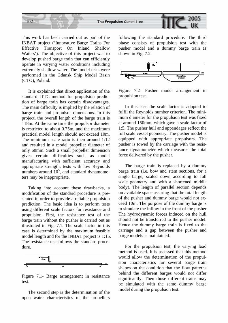
102 The Propulsion Committee
This work has been carried out as part of the INBAT project (‘Innovative Barge Trains For Effective Transport On Inland Shallow Waters’). The objective of this project was to develop pushed barge train that can efficiently operate in varying water conditions including extremely shallow water. The model tests were performed in the Gdansk Ship Model Basin (CTO), Poland.
It is explained that direct application of the standard ITTC method for propulsion predic-tion of barge train has certain disadvantages. The main difficulty is implied by the relation of barge train and propulsor dimensions. In this project, the overall length of the barge train is 118m. At the same time the propulsor diameter is restricted to about 0.75m, and the maximum practical model length should not exceed 10m. The minimum scale ratio is then around 1:12 and resulted in a model propeller diameter of only 60mm. Such a small propeller dimension gives certain difficulties such as model manufacturing with sufficient accuracy and appropriate strength, tests with low Reynolds numbers around 105, and standard dynamome-ters may be inappropriate.
Taking into account these drawbacks, a modification of the standard procedure is pre-sented in order to provide a reliable propulsion prediction. The basic idea is to perform tests using different scale factors for resistance and propulsion. First, the resistance test of the barge train without the pusher is carried out as illustrated in Fig. 7.1. The scale factor in this case is determined by the maximum feasible model length and for the INBAT project is 1:15. The resistance test follows the standard proce-dure.
Figure 7.1- Barge arrangement in resistance test.
The second step is the determination of the open water characteristics of the propellers
following the standard procedure. The third phase consists of propulsion test with the pusher model and a dummy barge train as shown in Fig. 7.2.
Figure 7.2- Pusher model arrangement in propulsion test.
In this case the scale factor is adopted to fulfil the Reynolds number criterion. The mini-mum diameter for the propulsion test was fixed at around 150mm, which gave a scale factor of 1:5. The pusher hull and appendages reflect the full scale vessel geometry. The pusher model is equipped with appropriate propulsors. The pusher is towed by the carriage with the resis-tance dynamometer which measures the total force delivered by the pusher.
The barge train is replaced by a dummy barge train (i.e. bow and stem sections, for a single barge, scaled down according to full scale geometry and with a shortened middle body). The length of parallel section depends on available space assuring that the total length of the pusher and dummy barge would not ex-ceed 10m. The purpose of the dummy barge is to simulate the inflow in the front of the pusher. The hydrodynamic forces induced on the hull should not be transferred to the pusher model. Hence the dummy barge train is fixed to the carriage and a gap between the pusher and barge models is maintained.
For the propulsion test, the varying load method is used. It is assessed that this method would allow the determination of the propul-sion characteristics for several barge train shapes on the condition that the flow patterns behind the different barges would not differ significantly. Then those different trains may be simulated with the same dummy barge model during the propulsion test.
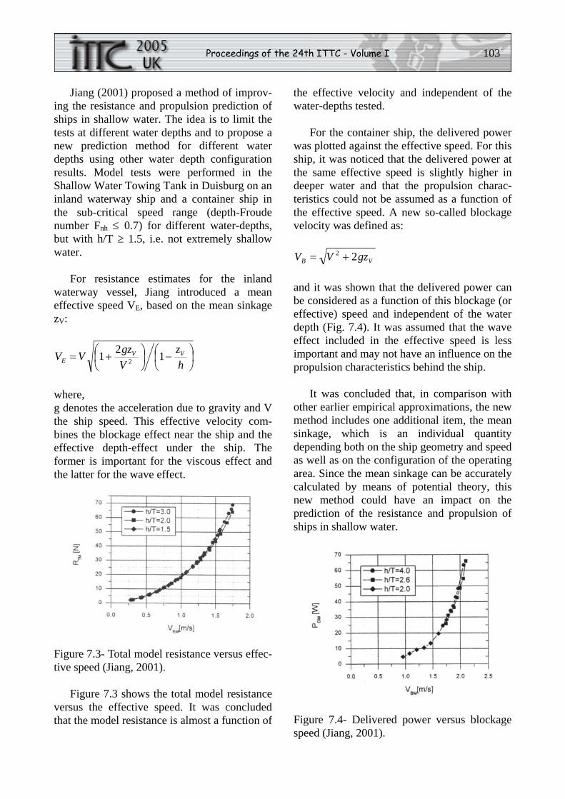
Proceedings of the 24th ITTC - Volume I 103
Jiang (2001) proposed a method of improv-ing the resistance and propulsion prediction of ships in shallow water. The idea is to limit the tests at different water depths and to propose a new prediction method for different water depths using other water depth configuration results. Model tests were performed in the Shallow Water Towing Tank in Duisburg on an inland waterway ship and a container ship in the sub-critical speed range (depth-Froude number Fnh ≤ 0.7) for different water-depths, but with h/T ≥ 1.5, i.e. not extremely shallow water.
For resistance estimates for the inland waterway vessel, Jiang introduced a mean effective speed VE, based on the mean sinkage zV:
⎟⎠⎞
⎜⎝⎛ −⎟
⎠⎞
⎜⎝⎛ +=
hz
VgzVV VV
E 121 2
where, g denotes the acceleration due to gravity and V the ship speed. This effective velocity com-bines the blockage effect near the ship and the effective depth-effect under the ship. The former is important for the viscous effect and the latter for the wave effect.
Figure 7.3- Total model resistance versus effec-tive speed (Jiang, 2001).
Figure 7.3 shows the total model resistance versus the effective speed. It was concluded that the model resistance is almost a function of
the effective velocity and independent of the water-depths tested.
For the container ship, the delivered power was plotted against the effective speed. For this ship, it was noticed that the delivered power at the same effective speed is slightly higher in deeper water and that the propulsion charac-teristics could not be assumed as a function of the effective speed. A new so-called blockage velocity was defined as:
VB gzVV 22 +=
and it was shown that the delivered power can be considered as a function of this blockage (or effective) speed and independent of the water depth (Fig. 7.4). It was assumed that the wave effect included in the effective speed is less important and may not have an influence on the propulsion characteristics behind the ship.
It was concluded that, in comparison with other earlier empirical approximations, the new method includes one additional item, the mean sinkage, which is an individual quantity depending both on the ship geometry and speed as well as on the configuration of the operating area. Since the mean sinkage can be accurately calculated by means of potential theory, this new method could have an impact on the prediction of the resistance and propulsion of ships in shallow water.
Figure 7.4- Delivered power versus blockage speed (Jiang, 2001).
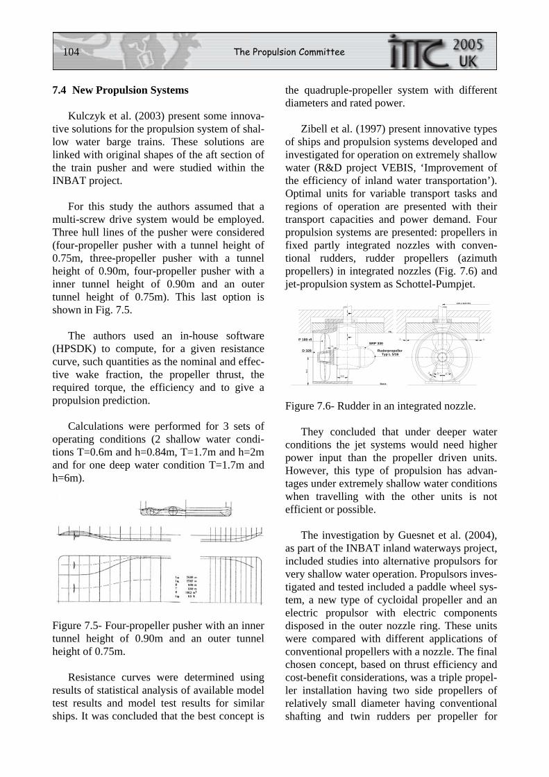
104 The Propulsion Committee
7.4 New Propulsion Systems
Kulczyk et al. (2003) present some innova-tive solutions for the propulsion system of shal-low water barge trains. These solutions are linked with original shapes of the aft section of the train pusher and were studied within the INBAT project.
For this study the authors assumed that a multi-screw drive system would be employed. Three hull lines of the pusher were considered (four-propeller pusher with a tunnel height of 0.75m, three-propeller pusher with a tunnel height of 0.90m, four-propeller pusher with a inner tunnel height of 0.90m and an outer tunnel height of 0.75m). This last option is shown in Fig. 7.5.
The authors used an in-house software (HPSDK) to compute, for a given resistance curve, such quantities as the nominal and effec-tive wake fraction, the propeller thrust, the required torque, the efficiency and to give a propulsion prediction.
Calculations were performed for 3 sets of operating conditions (2 shallow water condi-tions T=0.6m and h=0.84m, T=1.7m and h=2m and for one deep water condition T=1.7m and h=6m).
Figure 7.5- Four-propeller pusher with an inner tunnel height of 0.90m and an outer tunnel height of 0.75m.
Resistance curves were determined using results of statistical analysis of available model test results and model test results for similar ships. It was concluded that the best concept is
the quadruple-propeller system with different diameters and rated power.
Zibell et al. (1997) present innovative types of ships and propulsion systems developed and investigated for operation on extremely shallow water (R&D project VEBIS, ‘Improvement of the efficiency of inland water transportation’). Optimal units for variable transport tasks and regions of operation are presented with their transport capacities and power demand. Four propulsion systems are presented: propellers in fixed partly integrated nozzles with conven-tional rudders, rudder propellers (azimuth propellers) in integrated nozzles (Fig. 7.6) and jet-propulsion system as Schottel-Pumpjet.
Basis
TS
59.2
7.0
20.8
D 328
P 189 r/lSRP 330
RuderpropellerTyp L 5/16
158.3 aus MS
1452 2
27 273
Figure 7.6- Rudder in an integrated nozzle.
They concluded that under deeper water conditions the jet systems would need higher power input than the propeller driven units. However, this type of propulsion has advan-tages under extremely shallow water conditions when travelling with the other units is not efficient or possible.
The investigation by Guesnet et al. (2004), as part of the INBAT inland waterways project, included studies into alternative propulsors for very shallow water operation. Propulsors inves-tigated and tested included a paddle wheel sys-tem, a new type of cycloidal propeller and an electric propulsor with electric components disposed in the outer nozzle ring. These units were compared with different applications of conventional propellers with a nozzle. The final chosen concept, based on thrust efficiency and cost-benefit considerations, was a triple propel-ler installation having two side propellers of relatively small diameter having conventional shafting and twin rudders per propeller for
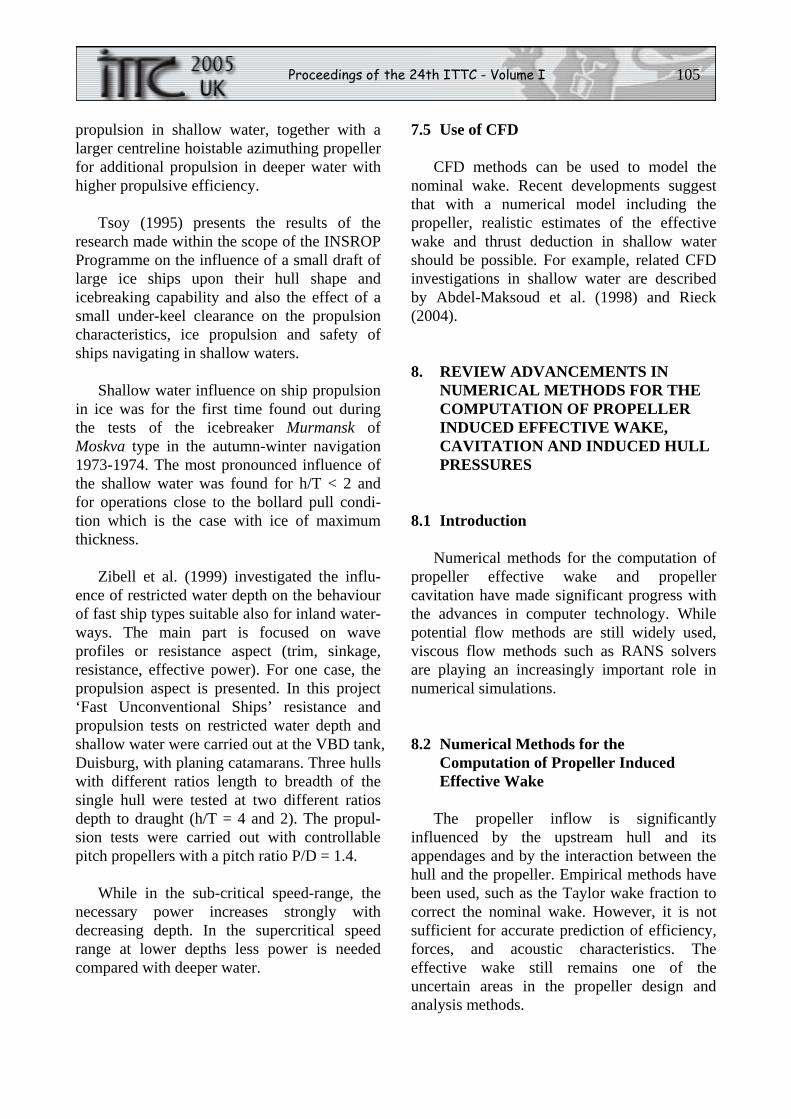
Proceedings of the 24th ITTC - Volume I 105
propulsion in shallow water, together with a larger centreline hoistable azimuthing propeller for additional propulsion in deeper water with higher propulsive efficiency.
Tsoy (1995) presents the results of the research made within the scope of the INSROP Programme on the influence of a small draft of large ice ships upon their hull shape and icebreaking capability and also the effect of a small under-keel clearance on the propulsion characteristics, ice propulsion and safety of ships navigating in shallow waters.
Shallow water influence on ship propulsion in ice was for the first time found out during the tests of the icebreaker Murmansk of Moskva type in the autumn-winter navigation 1973-1974. The most pronounced influence of the shallow water was found for h/T < 2 and for operations close to the bollard pull condi-tion which is the case with ice of maximum thickness.
Zibell et al. (1999) investigated the influ-ence of restricted water depth on the behaviour of fast ship types suitable also for inland water-ways. The main part is focused on wave profiles or resistance aspect (trim, sinkage, resistance, effective power). For one case, the propulsion aspect is presented. In this project ‘Fast Unconventional Ships’ resistance and propulsion tests on restricted water depth and shallow water were carried out at the VBD tank, Duisburg, with planing catamarans. Three hulls with different ratios length to breadth of the single hull were tested at two different ratios depth to draught (h/T = 4 and 2). The propul-sion tests were carried out with controllable pitch propellers with a pitch ratio P/D = 1.4.
While in the sub-critical speed-range, the necessary power increases strongly with decreasing depth. In the supercritical speed range at lower depths less power is needed compared with deeper water.
7.5 Use of CFD
CFD methods can be used to model the nominal wake. Recent developments suggest that with a numerical model including the propeller, realistic estimates of the effective wake and thrust deduction in shallow water should be possible. For example, related CFD investigations in shallow water are described by Abdel-Maksoud et al. (1998) and Rieck (2004).
8. REVIEW ADVANCEMENTS IN NUMERICAL METHODS FOR THE COMPUTATION OF PROPELLER INDUCED EFFECTIVE WAKE, CAVITATION AND INDUCED HULL PRESSURES
8.1 Introduction
Numerical methods for the computation of propeller effective wake and propeller cavitation have made significant progress with the advances in computer technology. While potential flow methods are still widely used, viscous flow methods such as RANS solvers are playing an increasingly important role in numerical simulations.
8.2 Numerical Methods for the Computation of Propeller Induced Effective Wake
The propeller inflow is significantly influenced by the upstream hull and its appendages and by the interaction between the hull and the propeller. Empirical methods have been used, such as the Taylor wake fraction to correct the nominal wake. However, it is not sufficient for accurate prediction of efficiency, forces, and acoustic characteristics. The effective wake still remains one of the uncertain areas in the propeller design and analysis methods.
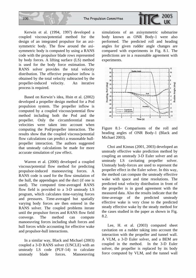
106 The Propulsion Committee
Kerwin et al. (1994, 1997) developed a coupled viscous/potential method for the design of an integrated propulsor for an axi-symmetric body. The flow around the axi-symmetric body is computed by using a RANS code with the propulsor blade rows represented by body forces. A lifting surface (LS) method is used for the body force estimation. The RANS solver provides the total velocity distribution. The effective propulsor inflow is obtained by the total velocity subtracted by the propeller-induced velocity. An iterative process is required.
Based on Kerwin’s idea, Hsin et al. (2002) developed a propeller design method for a Pod propulsion system. The propeller inflow is computed by a coupled viscous/potential flow method including both the Pod and the propeller. Only the circumferential mean velocities were taken into account when computing the Pod/propeller interaction. The results show that the coupled viscous/potential flow calculations can predict a reasonable hull-propeller interaction. The authors suggested that unsteady calculations be made for more accurate simulation of yaw effect.
Warren et al. (2000) developed a coupled viscous/potential flow method for predicting propulsor-induced manoeuvring forces. A RANS code is used for the flow simulation of the hull, the appendages and the duct (if one is used). The computed time-averaged RANS flow field is provided to a 3-D unsteady LS program, which calculates time-varying forces and pressures. Time-averaged but spatially varying body forces are then entered in the RANS solver. The coupled problems iterate until the propulsor forces and RANS flow field converge. The method can compute manoeuvring forces including shaft forces and hull forces while accounting for effective wake and propulsor-hull interactions.
In a similar way, Black and Michael (2003) coupled a 3-D RANS solver (UNCLE) with an unsteady LS code (PUF-14) to calculate unsteady blade forces. Manoeuvring
simulations of an axisymmetric submarine body known as ONR Body-1 were also performed. The predicted roll and heading angles for given rudder angle changes are compared with experiments in Fig. 8.1. The predictions are in a reasonable agreement with experiments.
Figure 8.1- Comparisons of the roll and heading angles of ONR Body-1 (Black and Michael 2003).
Choi and Kinnas (2001, 2003) developed an unsteady effective wake prediction method by coupling an unsteady 3-D Euler solver and an unsteady LS cavitating propeller solver. Unsteady body-forces are used to represent the propeller effect in the Euler solver. In this way, the method can compute the unsteady effective wake with space and time resolutions. The predicted total velocity distribution in front of the propeller is in good agreement with the measured data. Also the results indicate that the time-average of the predicted unsteady effective wake is very close to the predicted steady effective wake by the steady method for the cases studied in the paper as shown in Fig. 8.2.
Lee, H. et al. (2003) computed sheet cavitation on a rudder taking into account the interaction with the propeller and tunnel wall. A VLM, a 3-D Euler solver, and a BEM are coupled in the method. In the 3-D Euler solver, the propeller is replaced by its body force computed by VLM, and the tunnel wall
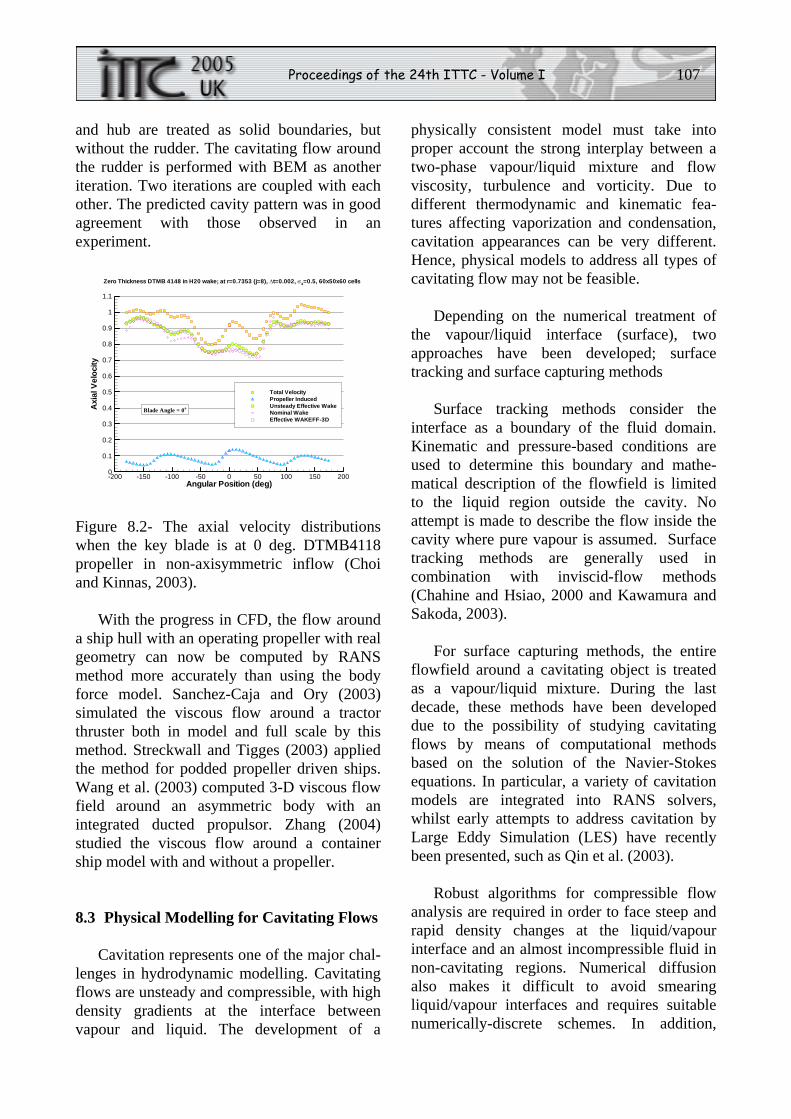
Proceedings of the 24th ITTC - Volume I 107
and hub are treated as solid boundaries, but without the rudder. The cavitating flow around the rudder is performed with BEM as another iteration. Two iterations are coupled with each other. The predicted cavity pattern was in good agreement with those observed in an experiment.
Angular Position (deg)
Axi
alV
eloc
ity
-200 -150 -100 -50 0 50 100 150 2000
0.1
0.2
0.3
0.4
0.5
0.6
0.7
0.8
0.9
1
1.1
Total VelocityPropeller InducedUnsteady Effective WakeNominal WakeEffective WAKEFF-3D
Zero Thickness DTMB 4148 in H20 wake; at r=0.7353 (j=8), Δt=0.002, σ4=0.5, 60x50x60 cells
Blade Angle = 0o
Figure 8.2- The axial velocity distributions when the key blade is at 0 deg. DTMB4118 propeller in non-axisymmetric inflow (Choi and Kinnas, 2003).
With the progress in CFD, the flow around a ship hull with an operating propeller with real geometry can now be computed by RANS method more accurately than using the body force model. Sanchez-Caja and Ory (2003) simulated the viscous flow around a tractor thruster both in model and full scale by this method. Streckwall and Tigges (2003) applied the method for podded propeller driven ships. Wang et al. (2003) computed 3-D viscous flow field around an asymmetric body with an integrated ducted propulsor. Zhang (2004) studied the viscous flow around a container ship model with and without a propeller.
8.3 Physical Modelling for Cavitating Flows
Cavitation represents one of the major chal-lenges in hydrodynamic modelling. Cavitating flows are unsteady and compressible, with high density gradients at the interface between vapour and liquid. The development of a
physically consistent model must take into proper account the strong interplay between a two-phase vapour/liquid mixture and flow viscosity, turbulence and vorticity. Due to different thermodynamic and kinematic fea-tures affecting vaporization and condensation, cavitation appearances can be very different. Hence, physical models to address all types of cavitating flow may not be feasible.
Depending on the numerical treatment of the vapour/liquid interface (surface), two approaches have been developed; surface tracking and surface capturing methods
Surface tracking methods consider the interface as a boundary of the fluid domain. Kinematic and pressure-based conditions are used to determine this boundary and mathe-matical description of the flowfield is limited to the liquid region outside the cavity. No attempt is made to describe the flow inside the cavity where pure vapour is assumed. Surface tracking methods are generally used in combination with inviscid-flow methods (Chahine and Hsiao, 2000 and Kawamura and Sakoda, 2003).
For surface capturing methods, the entire flowfield around a cavitating object is treated as a vapour/liquid mixture. During the last decade, these methods have been developed due to the possibility of studying cavitating flows by means of computational methods based on the solution of the Navier-Stokes equations. In particular, a variety of cavitation models are integrated into RANS solvers, whilst early attempts to address cavitation by Large Eddy Simulation (LES) have recently been presented, such as Qin et al. (2003).
Robust algorithms for compressible flow analysis are required in order to face steep and rapid density changes at the liquid/vapour interface and an almost incompressible fluid in non-cavitating regions. Numerical diffusion also makes it difficult to avoid smearing liquid/vapour interfaces and requires suitable numerically-discrete schemes. In addition,
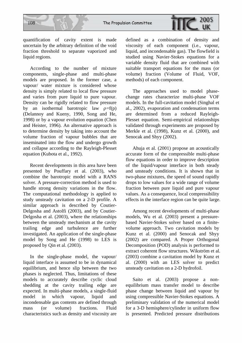
108 The Propulsion Committee
quantification of cavity extent is made uncertain by the arbitrary definition of the void fraction threshold to separate vaporized and liquid regions.
According to the number of mixture components, single-phase and multi-phase models are proposed. In the former case, a vapour/ water mixture is considered whose density is simply related to local flow pressure and varies from pure liquid to pure vapour. Density can be rigidly related to flow pressure by an isothermal barotropic law ρ=f(p) (Delannoy and Kueny, 1990, Song and He, 1998) or by a vapour evolution equation (Chen and Heister, 1996). An alternative approach is to determine density by taking into account the volume fraction of vapour bubbles that are inseminated into the flow and undergo growth and collapse according to the Rayleigh-Plesset equation (Kubota et al., 1992).
Recent developments in this area have been presented by Pouffary et al. (2003), who combine the barotropic model with a RANS solver. A pressure-correction method is used to handle strong density variations in the flow. The computational methodology is applied to study unsteady cavitation on a 2-D profile. A similar approach is described by Coutier-Delgosha and Astolfi (2003), and by Coutier-Delgosha et al. (2003), where the relationships between the unsteady mechanism at the cavity trailing edge and turbulence are further investigated. An application of the single-phase model by Song and He (1998) to LES is proposed by Qin et al. (2003).
In the single-phase model, the vapour/ liquid interface is assumed to be in dynamical equilibrium, and hence slip between the two phases is neglected. Thus, limitations of these models to accurately describe cyclic cloud shedding at the cavity trailing edge are expected. In multi-phase models, a single-fluid model in which vapour, liquid and incondensable gas contents are defined through mass (or volume) fractions. Fluid characteristics such as density and viscosity are
defined as a combination of density and viscosity of each component (i.e., vapour, liquid, and incondensable gas). The flowfield is studied using Navier-Stokes equations for a variable density fluid that are combined with suitable transport equations for the mass (or volume) fraction (Volume of Fluid, VOF, methods) of each component.
The approaches used to model phase-change rates characterize multi-phase VOF models. In the full-cavitation model (Singhal et al., 2002), evaporation and condensation terms are determined from a reduced Rayleigh-Plesset equation. Semi-empirical relationships validated through experiments are proposed by Merkle et al. (1998), Kunz et al. (2000), and Senocak and Shyy (2002).
Ahuja et al. (2001) propose an acoustically accurate form of the compressible multi-phase flow equations in order to improve description of the liquid/vapour interface in both steady and unsteady conditions. It is shown that in two-phase mixtures, the speed of sound rapidly drops to low values for a wide range of volume fraction between pure liquid and pure vapour values. As a consequence, local compressibility effects in the interface region can be quite large.
Among recent developments of multi-phase models, Wu et al. (2003) present a pressure-based Navier-Stokes solver based on a finite-volume approach. Two cavitation models by Kunz et al. (2000) and Senocak and Shyy (2002) are compared. A Proper Orthogonal Decomposition (POD) analysis is performed to extract coherent flow structures. Wikström et al. (2003) combine a cavitation model by Kunz et al. (2000) with an LES solver to predict unsteady cavitation on a 2-D hydrofoil.
Saito et al. (2003) propose a non-equilibrium mass transfer model to describe phase change between liquid and vapour by using compressible Navier-Stokes equations. A preliminary validation of the numerical model for a 3-D hemisphere/cylinder in uniform flow is presented. Predicted pressure distributions
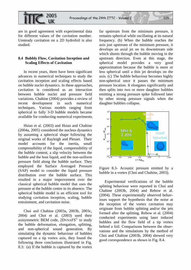
Proceedings of the 24th ITTC - Volume I 109
are in good agreement with experimental data for different values of the cavitation number. Unsteady cavitation on a 2D hydrofoil is also studied.
8.4 Bubbly Flow, Cavitation Inception and Scaling Effects of Cavitation
In recent years, there have been significant advances in numerical techniques to study the cavitation inception and scaling effects based on bubble nuclei dynamics. In these approaches, cavitation is considered as an interaction between bubble nuclei and pressure field variations. Chahine (2004) provides a review of recent development in such numerical techniques. Various models ranging from spherical to fully 3-D bubble models became available for conducting numerical experiments.
Hsiao et al. (2003) and Hsiao and Chahine (2004a, 2005) considered the nucleus dynamics by assuming a spherical shape following the original works of Rayleigh and Plesset. Their model accounts for the inertia, small compressibility of the liquid, compressibility of the bubble content, a slip velocity between the bubble and the host liquid, and the non-uniform pressure field along the bubble surface. They employed the Surface Averaged Pressure (SAP) model to consider the liquid pressure distribution over the bubble surface. This resulted in a major improvement over the classical spherical bubble model that uses the pressure at the bubble centre in its absence. The spherical bubble model is an efficient tool for studying cavitation inception, scaling, bubble entrainment, and cavitation noise.
Choi and Chahine (2003a, 2003b, 2003c, 2004) and Choi et al. (2003) used their axisymmetric BEM code, 2DYNAFS© to study the bubble deformation, elongation, splitting, and non-spherical sound generation. By simulating the dynamic behaviour of bubbles captured on a tip vortex axis, they found the following three conclusions illustrated in Fig. 8.3: (a) If the bubble is captured by the vortex
far upstream from the minimum pressure, it remains spherical while oscillating at its natural frequency. (b) When the bubble reaches the axis just upstream of the minimum pressure, it develops an axial jet on its downstream side which shoots through the bubble moving in the upstream direction. Even at this stage, the spherical model provides a very good approximation because the bubble is more or less spherical until a thin jet develops on the axis. (c) The bubble behaviour becomes highly non-spherical once it passes the minimum pressure location. It elongates significantly and then splits into two or more daughter bubbles emitting a strong pressure spike followed later by other strong pressure signals when the daughter bubbles collapse.
σ / -Cpmin
Pac
oust
ic/P
amb
0.75 0.8 0.85 0.9 0.95 1 1.0510-6
10-5
10-4
10-3
10-2
10-1
100
p
Figure 8.3- Acoustic pressure emitted by a bubble in a vortex (Choi and Chahine, 2003).
Experimental verifications of the bubble splitting behaviour were reported in Choi and Chahine (2003b, 2004) and Rebow et al. (2004). These experimentally observed behav-iours support the hypothesis that the noise at the inception of the vortex cavitation may originate from bubble splitting and/or the jets formed after the splitting. Rebow et al. (2004) conducted experiments using laser induced bubbles and the flow field of a tip vortex behind a foil. Comparisons between the obser-vations and the simulations by the method of Choi and Chahine (2003b, 2004) showed very good correspondence as shown in Fig. 8.4.
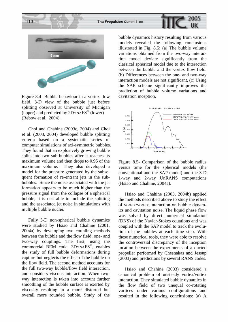
110 The Propulsion Committee
Figure 8.4- Bubble behaviour in a vortex flow field. 3-D view of the bubble just before splitting observed at University of Michigan (upper) and predicted by 2DYNAFS© (lower) (Rebow et al., 2004).
Choi and Chahine (2003c, 2004) and Choi et al. (2003, 2004) developed bubble splitting criteria based on a systematic series of computer simulations of axi-symmetric bubbles. They found that an explosively growing bubble splits into two sub-bubbles after it reaches its maximum volume and then drops to 0.95 of the maximum volume. They also developed a model for the pressure generated by the subse-quent formation of re-entrant jets in the sub-bubbles. Since the noise associated with the jet formation appears to be much higher than the pressure signal from the collapse of a spherical bubble, it is desirable to include the splitting and the associated jet noise in simulations with multiple bubble nuclei.
Fully 3-D non-spherical bubble dynamics were studied by Hsiao and Chahine (2001, 2004a) by developing two coupling methods between the bubble and the flow field; one- and two-way couplings. The first, using the commercial BEM code, 3DYNAFS©, enables the study of full bubble deformations during capture but neglects the effect of the bubble on the flow field. The second method accounts for the full two-way bubble/flow field interaction, and considers viscous interaction. When two-way interaction is taken into account further smoothing of the bubble surface is exerted by viscosity resulting in a more distorted but overall more rounded bubble. Study of the
bubble dynamics history resulting from various models revealed the following conclusions illustrated in Fig. 8.5: (a) The bubble volume variations obtained from the two-way interac-tion model deviate significantly from the classical spherical model due to the interaction between the bubble and the vortex flow field. (b) Differences between the one- and two-way interaction models are not significant. (c) Using the SAP scheme significantly improves the prediction of bubble volume variations and cavitation inception.
Figure 8.5- Comparison of the bubble radius versus time for the spherical models (the conventional and the SAP model) and the 3-D 1-way and 2-way UnRANS computations (Hsiao and Chahine, 2004a).
Hsiao and Chahine (2003, 2004b) applied the methods described above to study the effect of vortex/vortex interaction on bubble dynam-ics and cavitation noise. The liquid phase flow was solved by direct numerical simulation (DNS) of the Navier-Stokes equations and was coupled with the SAP model to track the evolu-tion of the bubbles at each time step. With these numerical tools, they were able to resolve the controversial discrepancy of the inception location between the experiments of a ducted propeller performed by Chesnakas and Jessup (2003) and predictions by several RANS codes.
Hsiao and Chahine (2003) considered a canonical problem of unsteady vortex/vortex interaction. They simulated bubble dynamics in the flow field of two unequal co-rotating vortices under various configurations and resulted in the following conclusions: (a) A
Conventional Spherical
SAP Spherical
1-Way 3D
2-Way 3D
T im e ( s e c )
R(m
)
0 .0 4 0 .0 5 0 .0 6 0 .0 7 0 .0 8 0 .0 9 0 .1
0 .0 0 1
0 .0 0 2
0 .0 0 3
0 .0 0 4
0 .0 0 5
0 .0 0 6
0 .0 0 7S p h e ric a l M o d e l N o S A PS p h e ric a l M o d e l W ith S A PO n e - W a y N o n - S p h e ric a l M o d e lT w o - W a y N o n - S p h e ric a l M o d e l
R e = 2 .8 8 x 1 0 6 R 0 = 5 0 μ m σ = 2 .5
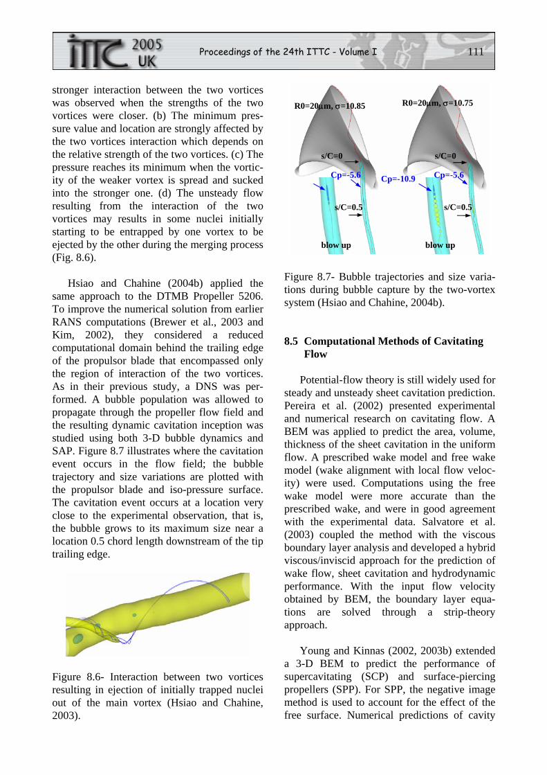
Proceedings of the 24th ITTC - Volume I 111
stronger interaction between the two vortices was observed when the strengths of the two vortices were closer. (b) The minimum pres-sure value and location are strongly affected by the two vortices interaction which depends on the relative strength of the two vortices. (c) The pressure reaches its minimum when the vortic-ity of the weaker vortex is spread and sucked into the stronger one. (d) The unsteady flow resulting from the interaction of the two vortices may results in some nuclei initially starting to be entrapped by one vortex to be ejected by the other during the merging process (Fig. 8.6).
Hsiao and Chahine (2004b) applied the same approach to the DTMB Propeller 5206. To improve the numerical solution from earlier RANS computations (Brewer et al., 2003 and Kim, 2002), they considered a reduced computational domain behind the trailing edge of the propulsor blade that encompassed only the region of interaction of the two vortices. As in their previous study, a DNS was per-formed. A bubble population was allowed to propagate through the propeller flow field and the resulting dynamic cavitation inception was studied using both 3-D bubble dynamics and SAP. Figure 8.7 illustrates where the cavitation event occurs in the flow field; the bubble trajectory and size variations are plotted with the propulsor blade and iso-pressure surface. The cavitation event occurs at a location very close to the experimental observation, that is, the bubble grows to its maximum size near a location 0.5 chord length downstream of the tip trailing edge.
Figure 8.6- Interaction between two vortices resulting in ejection of initially trapped nuclei out of the main vortex (Hsiao and Chahine, 2003).
Figure 8.7- Bubble trajectories and size varia-tions during bubble capture by the two-vortex system (Hsiao and Chahine, 2004b).
8.5 Computational Methods of Cavitating Flow
Potential-flow theory is still widely used for steady and unsteady sheet cavitation prediction. Pereira et al. (2002) presented experimental and numerical research on cavitating flow. A BEM was applied to predict the area, volume, thickness of the sheet cavitation in the uniform flow. A prescribed wake model and free wake model (wake alignment with local flow veloc-ity) were used. Computations using the free wake model were more accurate than the prescribed wake, and were in good agreement with the experimental data. Salvatore et al. (2003) coupled the method with the viscous boundary layer analysis and developed a hybrid viscous/inviscid approach for the prediction of wake flow, sheet cavitation and hydrodynamic performance. With the input flow velocity obtained by BEM, the boundary layer equa-tions are solved through a strip-theory approach.
Young and Kinnas (2002, 2003b) extended a 3-D BEM to predict the performance of supercavitating (SCP) and surface-piercing propellers (SPP). For SPP, the negative image method is used to account for the effect of the free surface. Numerical predictions of cavity
s/C=0.5
Cp=-5.6
s/C=0
s/C=0.5
Cp=-5.6 Cp=-10.9
s/C=0
R0=20μm, σ=10.85 R0=20μm, σ=10.75
blow up blow up
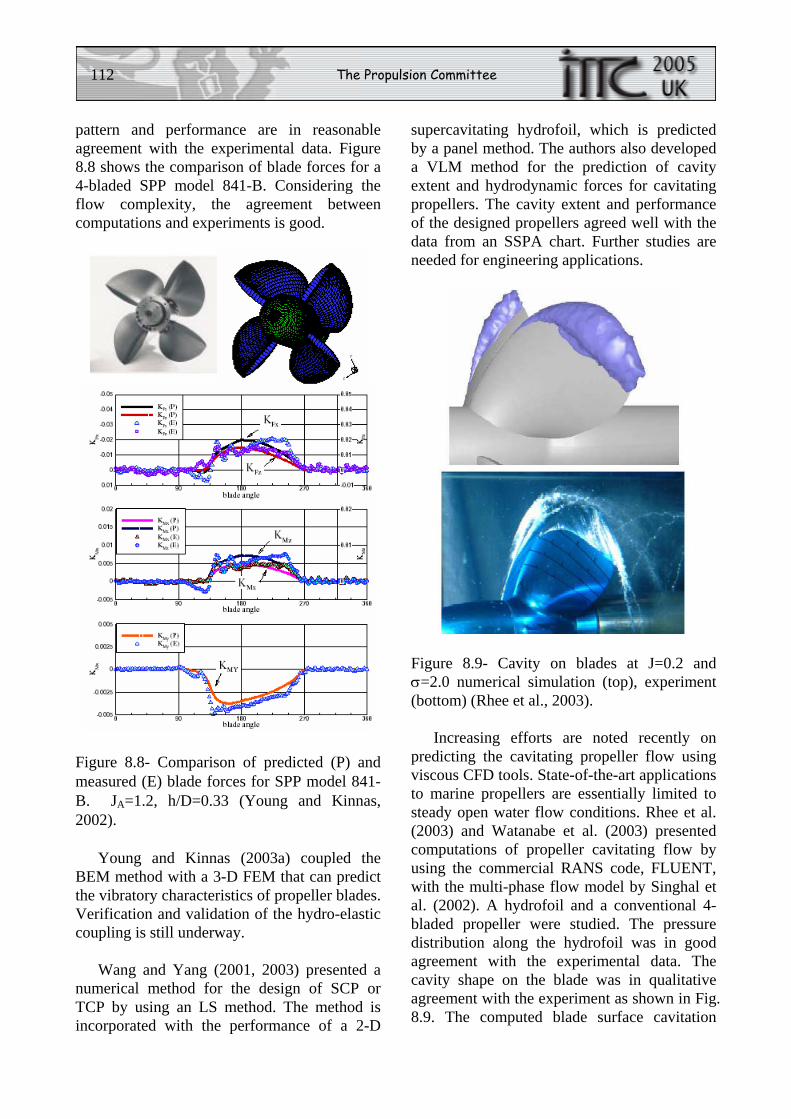
112 The Propulsion Committee
pattern and performance are in reasonable agreement with the experimental data. Figure 8.8 shows the comparison of blade forces for a 4-bladed SPP model 841-B. Considering the flow complexity, the agreement between computations and experiments is good.
Figure 8.8- Comparison of predicted (P) and measured (E) blade forces for SPP model 841-B. JA=1.2, h/D=0.33 (Young and Kinnas, 2002).
Young and Kinnas (2003a) coupled the BEM method with a 3-D FEM that can predict the vibratory characteristics of propeller blades. Verification and validation of the hydro-elastic coupling is still underway.
Wang and Yang (2001, 2003) presented a numerical method for the design of SCP or TCP by using an LS method. The method is incorporated with the performance of a 2-D
supercavitating hydrofoil, which is predicted by a panel method. The authors also developed a VLM method for the prediction of cavity extent and hydrodynamic forces for cavitating propellers. The cavity extent and performance of the designed propellers agreed well with the data from an SSPA chart. Further studies are needed for engineering applications.
Figure 8.9- Cavity on blades at J=0.2 and σ=2.0 numerical simulation (top), experiment (bottom) (Rhee et al., 2003).
Increasing efforts are noted recently on predicting the cavitating propeller flow using viscous CFD tools. State-of-the-art applications to marine propellers are essentially limited to steady open water flow conditions. Rhee et al. (2003) and Watanabe et al. (2003) presented computations of propeller cavitating flow by using the commercial RANS code, FLUENT, with the multi-phase flow model by Singhal et al. (2002). A hydrofoil and a conventional 4-bladed propeller were studied. The pressure distribution along the hydrofoil was in good agreement with the experimental data. The cavity shape on the blade was in qualitative agreement with the experiment as shown in Fig. 8.9. The computed blade surface cavitation
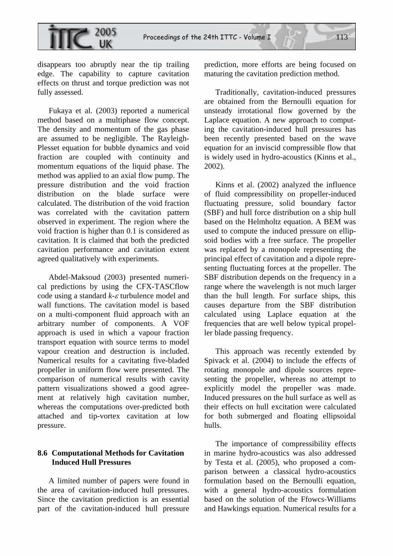
Proceedings of the 24th ITTC - Volume I 113
disappears too abruptly near the tip trailing edge. The capability to capture cavitation effects on thrust and torque prediction was not fully assessed.
Fukaya et al. (2003) reported a numerical method based on a multiphase flow concept. The density and momentum of the gas phase are assumed to be negligible. The Rayleigh-Plesset equation for bubble dynamics and void fraction are coupled with continuity and momentum equations of the liquid phase. The method was applied to an axial flow pump. The pressure distribution and the void fraction distribution on the blade surface were calculated. The distribution of the void fraction was correlated with the cavitation pattern observed in experiment. The region where the void fraction is higher than 0.1 is considered as cavitation. It is claimed that both the predicted cavitation performance and cavitation extent agreed qualitatively with experiments.
Abdel-Maksoud (2003) presented numeri-cal predictions by using the CFX-TASCflow code using a standard k-ε turbulence model and wall functions. The cavitation model is based on a multi-component fluid approach with an arbitrary number of components. A VOF approach is used in which a vapour fraction transport equation with source terms to model vapour creation and destruction is included. Numerical results for a cavitating five-bladed propeller in uniform flow were presented. The comparison of numerical results with cavity pattern visualizations showed a good agree-ment at relatively high cavitation number, whereas the computations over-predicted both attached and tip-vortex cavitation at low pressure.
8.6 Computational Methods for Cavitation Induced Hull Pressures
A limited number of papers were found in the area of cavitation-induced hull pressures. Since the cavitation prediction is an essential part of the cavitation-induced hull pressure
prediction, more efforts are being focused on maturing the cavitation prediction method.
Traditionally, cavitation-induced pressures are obtained from the Bernoulli equation for unsteady irrotational flow governed by the Laplace equation. A new approach to comput-ing the cavitation-induced hull pressures has been recently presented based on the wave equation for an inviscid compressible flow that is widely used in hydro-acoustics (Kinns et al., 2002).
Kinns et al. (2002) analyzed the influence of fluid compressibility on propeller-induced fluctuating pressure, solid boundary factor (SBF) and hull force distribution on a ship hull based on the Helmholtz equation. A BEM was used to compute the induced pressure on ellip-soid bodies with a free surface. The propeller was replaced by a monopole representing the principal effect of cavitation and a dipole repre-senting fluctuating forces at the propeller. The SBF distribution depends on the frequency in a range where the wavelength is not much larger than the hull length. For surface ships, this causes departure from the SBF distribution calculated using Laplace equation at the frequencies that are well below typical propel-ler blade passing frequency.
This approach was recently extended by Spivack et al. (2004) to include the effects of rotating monopole and dipole sources repre-senting the propeller, whereas no attempt to explicitly model the propeller was made. Induced pressures on the hull surface as well as their effects on hull excitation were calculated for both submerged and floating ellipsoidal hulls.
The importance of compressibility effects in marine hydro-acoustics was also addressed by Testa et al. (2005), who proposed a com-parison between a classical hydro-acoustics formulation based on the Bernoulli equation, with a general hydro-acoustics formulation based on the solution of the Ffowcs-Williams and Hawkings equation. Numerical results for a
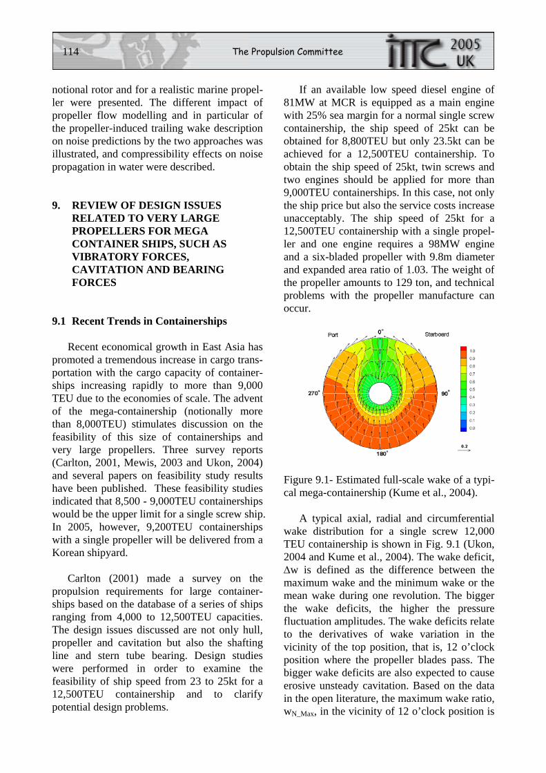
114 The Propulsion Committee
notional rotor and for a realistic marine propel-ler were presented. The different impact of propeller flow modelling and in particular of the propeller-induced trailing wake description on noise predictions by the two approaches was illustrated, and compressibility effects on noise propagation in water were described.
9. REVIEW OF DESIGN ISSUES RELATED TO VERY LARGE PROPELLERS FOR MEGA CONTAINER SHIPS, SUCH AS VIBRATORY FORCES, CAVITATION AND BEARING FORCES
9.1 Recent Trends in Containerships
Recent economical growth in East Asia has promoted a tremendous increase in cargo trans-portation with the cargo capacity of container-ships increasing rapidly to more than 9,000 TEU due to the economies of scale. The advent of the mega-containership (notionally more than 8,000TEU) stimulates discussion on the feasibility of this size of containerships and very large propellers. Three survey reports (Carlton, 2001, Mewis, 2003 and Ukon, 2004) and several papers on feasibility study results have been published. These feasibility studies indicated that 8,500 - 9,000TEU containerships would be the upper limit for a single screw ship. In 2005, however, 9,200TEU containerships with a single propeller will be delivered from a Korean shipyard.
Carlton (2001) made a survey on the propulsion requirements for large container-ships based on the database of a series of ships ranging from 4,000 to 12,500TEU capacities. The design issues discussed are not only hull, propeller and cavitation but also the shafting line and stern tube bearing. Design studies were performed in order to examine the feasibility of ship speed from 23 to 25kt for a 12,500TEU containership and to clarify potential design problems.
If an available low speed diesel engine of 81MW at MCR is equipped as a main engine with 25% sea margin for a normal single screw containership, the ship speed of 25kt can be obtained for 8,800TEU but only 23.5kt can be achieved for a 12,500TEU containership. To obtain the ship speed of 25kt, twin screws and two engines should be applied for more than 9,000TEU containerships. In this case, not only the ship price but also the service costs increase unacceptably. The ship speed of 25kt for a 12,500TEU containership with a single propel-ler and one engine requires a 98MW engine and a six-bladed propeller with 9.8m diameter and expanded area ratio of 1.03. The weight of the propeller amounts to 129 ton, and technical problems with the propeller manufacture can occur.
Figure 9.1- Estimated full-scale wake of a typi-cal mega-containership (Kume et al., 2004).
A typical axial, radial and circumferential wake distribution for a single screw 12,000 TEU containership is shown in Fig. 9.1 (Ukon, 2004 and Kume et al., 2004). The wake deficit, Δw is defined as the difference between the maximum wake and the minimum wake or the mean wake during one revolution. The bigger the wake deficits, the higher the pressure fluctuation amplitudes. The wake deficits relate to the derivatives of wake variation in the vicinity of the top position, that is, 12 o’clock position where the propeller blades pass. The bigger wake deficits are also expected to cause erosive unsteady cavitation. Based on the data in the open literature, the maximum wake ratio, wN_Max, in the vicinity of 12 o’clock position is
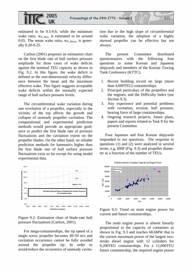
Proceedings of the 24th ITTC - Volume I 115
estimated to be 0.5-0.6, while the minimum wake ratio, wN_Min, is estimated to be around 0.05. The mean wake ratio, wN_Mean, is gener-ally 0.20-0.25.
Carlton (2001) proposes an estimation chart on the first blade rate of hull surface pressure amplitude for three cases of wake deficits against the nominal TEU capacity as shown in Fig. 9.2. In this figure, the wake deficit is defined as the non-dimensional velocity differ-ence between the mean and the maximum effective wake. This figure suggests acceptable wake deficits within the normally expected range of hull surface pressure levels.
The circumferential wake variation during one revolution of a propeller, especially in the vicinity of the top affects the growth and collapse of unsteady propeller cavitation. The computational and experimental prediction methods would provide an appropriate guid-ance to predict the first blade rate of pressure fluctuations and the cavitation extent on the propeller blades. On the other hand, no reliable prediction methods for harmonics higher than the first blade rate of hull surface pressure fluctuations exist so far except for using model experimental data.
0.0
2.0
4.0
6.0
8.0
10.0
12.0
14.0
3000 4000 5000 6000 7000 8000 9000 10000 11000 12000 13000
Nominal teu Capacity
Bla
de R
ate
Hul
l Sur
face
Pre
ssur
e (k
Pa)
Delta w = 0.2
0.3
0.4
Normally Expected Range of Radiated Hull Surface Pressuresfor a Container Ship
Figure 9.2- Estimation chart of blade-rate hull pressure fluctuations (Carlton, 2001).
For mega-containerships, the tip speed of a single screw propeller becomes 49-59 m/s and cavitation occurrence cannot be fully avoided around the propeller tip. In order to avoid/reduce the occurrence of unsteady cavita-
tion due to the high slope of circumferential wake variation, the adoption of a highly skewed propeller can be effective but not always.
The present Committee distributed questionnaires with the following four questions to some Korean and Japanese shipyards and members of the Korean Towing Tank Conference (KTTC).
1. Recent building record on large (more
than 4,000TEU) containerships. 2. Principal particulars of the propellers and
the engines, and the Difficulty Index (see Section 9.3).
3. Any experience and potential problems with cavitation, erosion, hull pressure, bearing force of large containerships.
4. Ongoing research projects, future plans, papers and reports related to Task 8 for the present Committee.
Four Japanese and four Korean shipyards responded to our questions. The response to questions (1) and (2) were analyzed in several terms, e.g. BHP (Fig. 9.3) and propeller diame-ter as a function of the number of TEUs.
Relation between Container Capacity and Engine Power
0
20,000
40,000
60,000
80,000
100,000
120,000
0 2,000 4,000 6,000 8,000 10,000 12,000 14,000
TEU
BHP [kW]
Existing
Study
Figure 9.3- Trend on main engine power for current and future containerships.
The main engine power is almost linearly proportional to the capacity of containers as shown in Fig. 9.3 and reaches 68.6MW that is the current maximum power of the largest two-stroke diesel engine with 12 cylinders for 9,200TEU containerships. For a 12,000TEU future containership, the required engine power
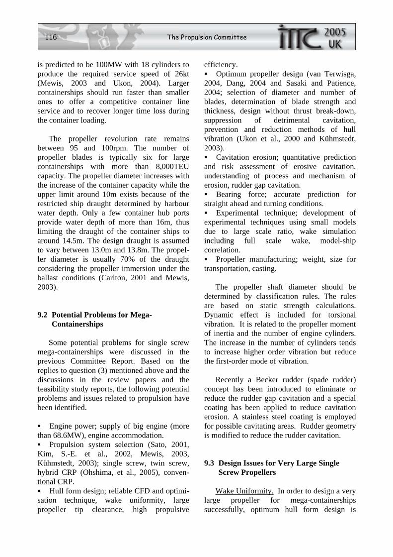
116 The Propulsion Committee
is predicted to be 100MW with 18 cylinders to produce the required service speed of 26kt (Mewis, 2003 and Ukon, 2004). Larger containerships should run faster than smaller ones to offer a competitive container line service and to recover longer time loss during the container loading.
The propeller revolution rate remains between 95 and 100rpm. The number of propeller blades is typically six for large containerships with more than 8,000TEU capacity. The propeller diameter increases with the increase of the container capacity while the upper limit around 10m exists because of the restricted ship draught determined by harbour water depth. Only a few container hub ports provide water depth of more than 16m, thus limiting the draught of the container ships to around 14.5m. The design draught is assumed to vary between 13.0m and 13.8m. The propel-ler diameter is usually 70% of the draught considering the propeller immersion under the ballast conditions (Carlton, 2001 and Mewis, 2003).
9.2 Potential Problems for Mega-Containerships
Some potential problems for single screw mega-containerships were discussed in the previous Committee Report. Based on the replies to question (3) mentioned above and the discussions in the review papers and the feasibility study reports, the following potential problems and issues related to propulsion have been identified.
Engine power; supply of big engine (more
than 68.6MW), engine accommodation. Propulsion system selection (Sato, 2001,
Kim, S.-E. et al., 2002, Mewis, 2003, Kühmstedt, 2003); single screw, twin screw, hybrid CRP (Ohshima, et al., 2005), conven-tional CRP. Hull form design; reliable CFD and optimi-
sation technique, wake uniformity, large propeller tip clearance, high propulsive
efficiency. Optimum propeller design (van Terwisga,
2004, Dang, 2004 and Sasaki and Patience, 2004; selection of diameter and number of blades, determination of blade strength and thickness, design without thrust break-down, suppression of detrimental cavitation, prevention and reduction methods of hull vibration (Ukon et al., 2000 and Kühmstedt, 2003). Cavitation erosion; quantitative prediction
and risk assessment of erosive cavitation, understanding of process and mechanism of erosion, rudder gap cavitation. Bearing force; accurate prediction for
straight ahead and turning conditions. Experimental technique; development of
experimental techniques using small models due to large scale ratio, wake simulation including full scale wake, model-ship correlation. Propeller manufacturing; weight, size for
transportation, casting.
The propeller shaft diameter should be determined by classification rules. The rules are based on static strength calculations. Dynamic effect is included for torsional vibration. It is related to the propeller moment of inertia and the number of engine cylinders. The increase in the number of cylinders tends to increase higher order vibration but reduce the first-order mode of vibration.
Recently a Becker rudder (spade rudder) concept has been introduced to eliminate or reduce the rudder gap cavitation and a special coating has been applied to reduce cavitation erosion. A stainless steel coating is employed for possible cavitating areas. Rudder geometry is modified to reduce the rudder cavitation.
9.3 Design Issues for Very Large Single Screw Propellers
Wake Uniformity. In order to design a very large propeller for mega-containerships successfully, optimum hull form design is
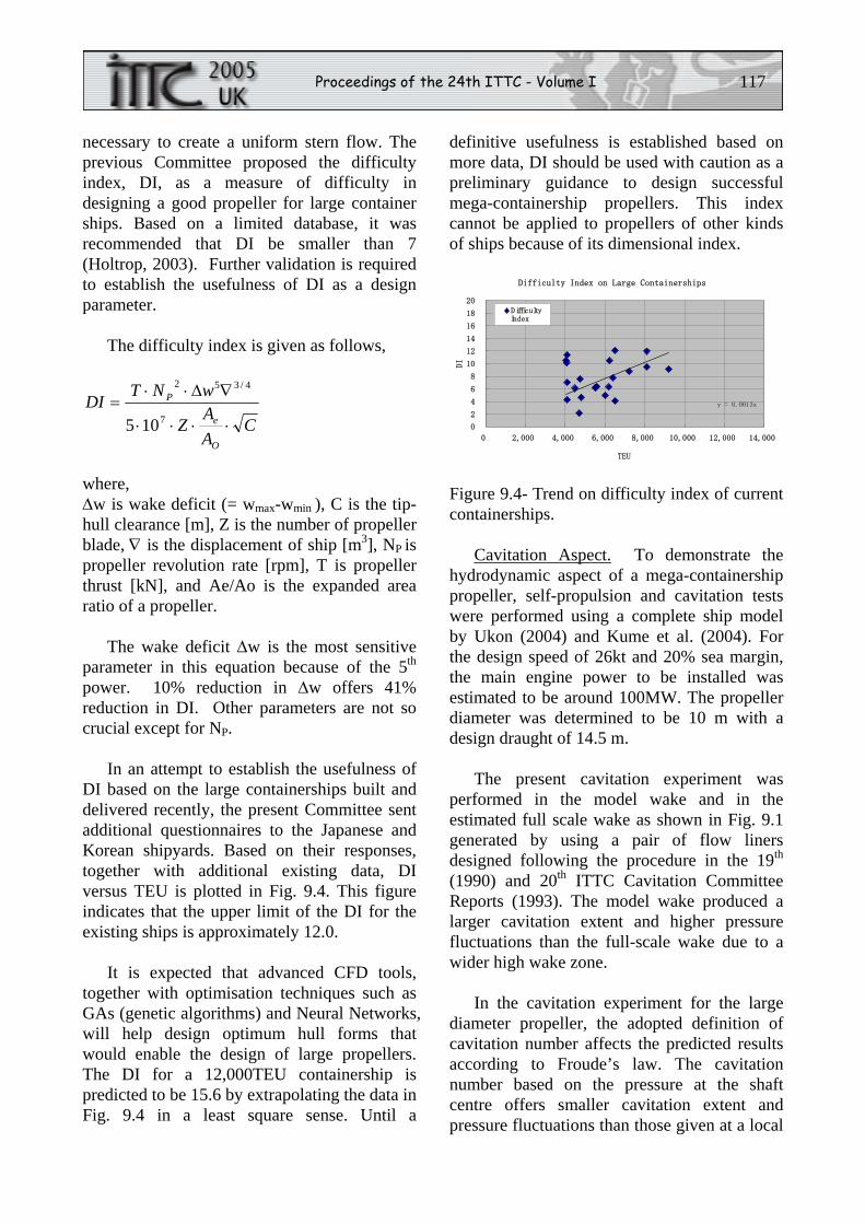
Proceedings of the 24th ITTC - Volume I 117
necessary to create a uniform stern flow. The previous Committee proposed the difficulty index, DI, as a measure of difficulty in designing a good propeller for large container ships. Based on a limited database, it was recommended that DI be smaller than 7 (Holtrop, 2003). Further validation is required to establish the usefulness of DI as a design parameter.
The difficulty index is given as follows,
CAA
Z
wNTDI
O
e
P
⋅⋅⋅⋅
∇Δ⋅⋅=
7
4/352
105
where, Δw is wake deficit (= wmax-wmin ), C is the tip-hull clearance [m], Z is the number of propeller blade, ∇ is the displacement of ship [m3], NP is propeller revolution rate [rpm], T is propeller thrust [kN], and Ae/Ao is the expanded area ratio of a propeller.
The wake deficit Δw is the most sensitive parameter in this equation because of the 5th power. 10% reduction in Δw offers 41% reduction in DI. Other parameters are not so crucial except for NP.
In an attempt to establish the usefulness of DI based on the large containerships built and delivered recently, the present Committee sent additional questionnaires to the Japanese and Korean shipyards. Based on their responses, together with additional existing data, DI versus TEU is plotted in Fig. 9.4. This figure indicates that the upper limit of the DI for the existing ships is approximately 12.0.
It is expected that advanced CFD tools, together with optimisation techniques such as GAs (genetic algorithms) and Neural Networks, will help design optimum hull forms that would enable the design of large propellers. The DI for a 12,000TEU containership is predicted to be 15.6 by extrapolating the data in Fig. 9.4 in a least square sense. Until a
definitive usefulness is established based on more data, DI should be used with caution as a preliminary guidance to design successful mega-containership propellers. This index cannot be applied to propellers of other kinds of ships because of its dimensional index.
Difficulty Index on Large Containerships
y = 0.0013x
0
2
4
6
8
10
12
14
16
18
20
0 2,000 4,000 6,000 8,000 10,000 12,000 14,000
TEUDI
D ifficultyIndex
Figure 9.4- Trend on difficulty index of current containerships.
Cavitation Aspect. To demonstrate the hydrodynamic aspect of a mega-containership propeller, self-propulsion and cavitation tests were performed using a complete ship model by Ukon (2004) and Kume et al. (2004). For the design speed of 26kt and 20% sea margin, the main engine power to be installed was estimated to be around 100MW. The propeller diameter was determined to be 10 m with a design draught of 14.5 m.
The present cavitation experiment was performed in the model wake and in the estimated full scale wake as shown in Fig. 9.1 generated by using a pair of flow liners designed following the procedure in the 19th (1990) and 20th ITTC Cavitation Committee Reports (1993). The model wake produced a larger cavitation extent and higher pressure fluctuations than the full-scale wake due to a wider high wake zone.
In the cavitation experiment for the large diameter propeller, the adopted definition of cavitation number affects the predicted results according to Froude’s law. The cavitation number based on the pressure at the shaft centre offers smaller cavitation extent and pressure fluctuations than those given at a local
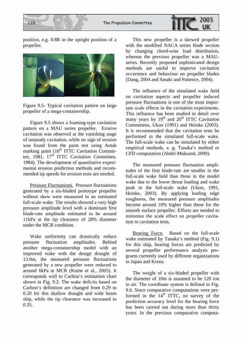
118 The Propulsion Committee
position, e.g. 0.8R in the upright position of a propeller.
Figure 9.5- Typical cavitation pattern on large propeller of a mega-containership.
Figure 9.5 shows a foaming-type cavitation pattern on a MAU series propeller. Erosive cavitation was observed at the vanishing stage of unsteady cavitation, while no sign of erosion was found from the paint test using Aotak marking paint (16th ITTC Cavitation Commit-tee, 1981, 17th ITTC Cavitation Committee, 1984). The development of quantitative experi-mental erosion prediction methods and recom-mended tip speeds for erosion tests are needed.
Pressure Fluctuations. Pressure fluctuations generated by a six-bladed prototype propeller without skew were measured in an estimated full-scale wake. The results showed a very high pressure amplitude level with a dominant first blade-rate amplitude estimated to be around 11kPa at the tip clearance of 28% diameter under the MCR condition.
Wake uniformity can drastically reduce pressure fluctuation amplitudes. Behind another mega-containership model with an improved wake with the design draught of 13.0m, the measured pressure fluctuations generated by a new propeller were reduced to around 6kPa at MCR (Kume et al., 2005). It corresponds well to Carlton’s estimation chart shown in Fig. 9.2. The wake deficits based on Carlton’s definition are changed from 0.29 to 0.20 for this shallow draught and wide beam ship, while the tip clearance was increased to 0.35.
This new propeller is a skewed propeller with the modified NACA series blade section by changing chord-wise load distribution, whereas the previous propeller was a MAU-series. Recently proposed sophisticated design methods are useful to improve cavitation occurrence and behaviour on propeller blades (Dang, 2004 and Sasaki and Patience, 2004).
The influence of the simulated wake field on cavitation aspects and propeller induced pressure fluctuations is one of the most impor-tant scale effects in the cavitation experiments. This influence has been studied in detail over many years by 19th and 20th ITTC Cavitation Committees, Ukon (1991) and Heinke (2003). It is recommended that the cavitation tests be performed in the simulated full-scale wake. The full-scale wake can be simulated by either empirical methods, e. g. Tanaka’s method or CFD computation (Abdel-Maksand, 2000).
The measured pressure fluctuation ampli-tudes of the first blade-rate are smaller in the full-scale wake field than those in the model wake due to the lower thrust loading and wake peak in the full-scale wake (Ukon, 1991, Heinke, 2003). By applying leading edge roughness, the measured pressure amplitudes became around 10% higher than those for the smooth surface propeller. Efforts are needed to minimize the scale effect on propeller cavita-tion in cavitation tests.
Bearing Force. Based on the full-scale wake estimated by Tanaka’s method (Fig. 9.1) for this ship, bearing forces are predicted by several propeller performance analysis pro-grams currently used by different organizations in Japan and Korea.
The weight of a six-bladed propeller with the diameter of 10m is assumed to be 120 ton in air. The coordinate system is defined in Fig. 9.6. Since comparative computations were per-formed in the 14th ITTC, no survey of the prediction accuracy level for the bearing force has been carried out during more than thirty years. In the previous comparative computa-
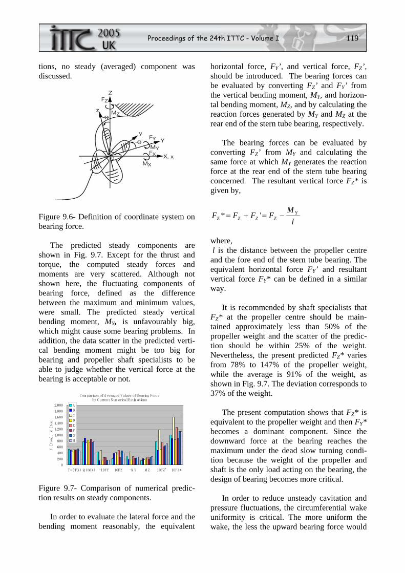
Proceedings of the 24th ITTC - Volume I 119
tions, no steady (averaged) component was discussed.
Figure 9.6- Definition of coordinate system on bearing force.
The predicted steady components are shown in Fig. 9.7. Except for the thrust and torque, the computed steady forces and moments are very scattered. Although not shown here, the fluctuating components of bearing force, defined as the difference between the maximum and minimum values, were small. The predicted steady vertical bending moment, MY, is unfavourably big, which might cause some bearing problems. In addition, the data scatter in the predicted verti-cal bending moment might be too big for bearing and propeller shaft specialists to be able to judge whether the vertical force at the bearing is acceptable or not.
C om parison of Averaged Values of Bearing Force
by C urrent Num erical Estim ations
0
200
400
600
800
1,000
1,200
1,400
1,600
1,800
2,000
T=(-FX) Q (=M X) -10FY 10FZ -M Y M Z 10FZ' 10FZ*
F [ton], M [ton-
A
B
C
D
E
F
G
H
Figure 9.7- Comparison of numerical predic-tion results on steady components.
In order to evaluate the lateral force and the bending moment reasonably, the equivalent
horizontal force, FY’, and vertical force, FZ’, should be introduced. The bearing forces can be evaluated by converting FZ’ and FY’ from the vertical bending moment, MY, and horizon-tal bending moment, MZ, and by calculating the reaction forces generated by MY and MZ at the rear end of the stern tube bearing, respectively.
The bearing forces can be evaluated by converting FZ’ from MY and calculating the same force at which MY generates the reaction force at the rear end of the stern tube bearing concerned. The resultant vertical force FZ* is given by,
lM
FFFF YZZZZ −=+= '*
where, l is the distance between the propeller centre and the fore end of the stern tube bearing. The equivalent horizontal force FY’ and resultant vertical force FY* can be defined in a similar way.
It is recommended by shaft specialists that FZ* at the propeller centre should be main-tained approximately less than 50% of the propeller weight and the scatter of the predic-tion should be within 25% of the weight. Nevertheless, the present predicted FZ* varies from 78% to 147% of the propeller weight, while the average is 91% of the weight, as shown in Fig. 9.7. The deviation corresponds to 37% of the weight.
The present computation shows that FZ* is equivalent to the propeller weight and then FY* becomes a dominant component. Since the downward force at the bearing reaches the maximum under the dead slow turning condi-tion because the weight of the propeller and shaft is the only load acting on the bearing, the design of bearing becomes more critical.
In order to reduce unsteady cavitation and pressure fluctuations, the circumferential wake uniformity is critical. The more uniform the wake, the less the upward bearing force would
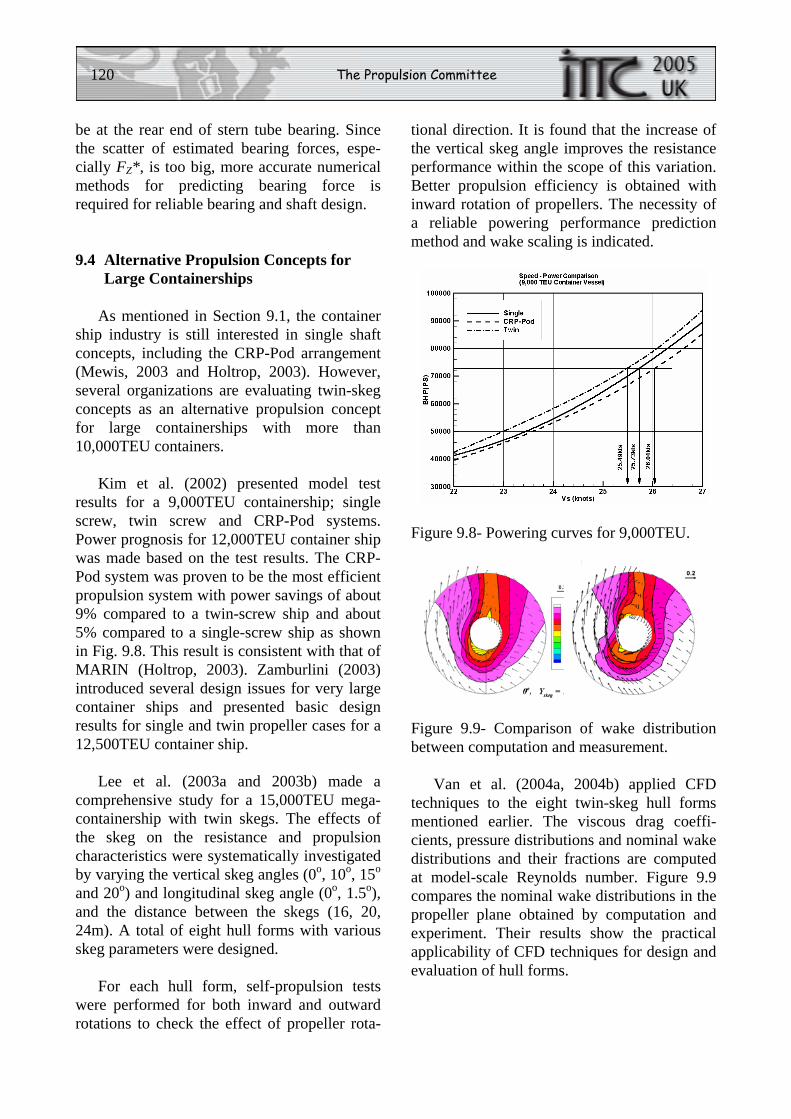
120 The Propulsion Committee
be at the rear end of stern tube bearing. Since the scatter of estimated bearing forces, espe-cially FZ*, is too big, more accurate numerical methods for predicting bearing force is required for reliable bearing and shaft design.
9.4 Alternative Propulsion Concepts for Large Containerships
As mentioned in Section 9.1, the container ship industry is still interested in single shaft concepts, including the CRP-Pod arrangement (Mewis, 2003 and Holtrop, 2003). However, several organizations are evaluating twin-skeg concepts as an alternative propulsion concept for large containerships with more than 10,000TEU containers.
Kim et al. (2002) presented model test results for a 9,000TEU containership; single screw, twin screw and CRP-Pod systems. Power prognosis for 12,000TEU container ship was made based on the test results. The CRP-Pod system was proven to be the most efficient propulsion system with power savings of about 9% compared to a twin-screw ship and about 5% compared to a single-screw ship as shown in Fig. 9.8. This result is consistent with that of MARIN (Holtrop, 2003). Zamburlini (2003) introduced several design issues for very large container ships and presented basic design results for single and twin propeller cases for a 12,500TEU container ship.
Lee et al. (2003a and 2003b) made a comprehensive study for a 15,000TEU mega-containership with twin skegs. The effects of the skeg on the resistance and propulsion characteristics were systematically investigated by varying the vertical skeg angles (0o, 10o, 15o and 20o) and longitudinal skeg angle (0o, 1.5o), and the distance between the skegs (16, 20, 24m). A total of eight hull forms with various skeg parameters were designed.
For each hull form, self-propulsion tests were performed for both inward and outward rotations to check the effect of propeller rota-
tional direction. It is found that the increase of the vertical skeg angle improves the resistance performance within the scope of this variation. Better propulsion efficiency is obtained with inward rotation of propellers. The necessity of a reliable powering performance prediction method and wake scaling is indicated.
Figure 9.8- Powering curves for 9,000TEU.
Figure 9.9- Comparison of wake distribution between computation and measurement.
Van et al. (2004a, 2004b) applied CFD techniques to the eight twin-skeg hull forms mentioned earlier. The viscous drag coeffi-cients, pressure distributions and nominal wake distributions and their fractions are computed at model-scale Reynolds number. Figure 9.9 compares the nominal wake distributions in the propeller plane obtained by computation and experiment. Their results show the practical applicability of CFD techniques for design and evaluation of hull forms.
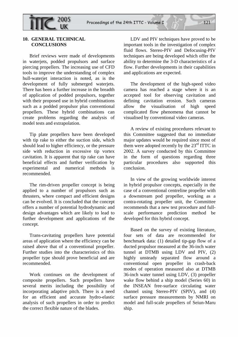
Proceedings of the 24th ITTC - Volume I 121
10. GENERAL TECHNICAL CONCLUSIONS
Brief reviews were made of developments in waterjets, podded propulsors and surface piercing propellers. The increasing use of CFD tools to improve the understanding of complex hull-waterjet interaction is noted, as is the development of fully submerged waterjets. There has been a further increase in the breadth of application of podded propulsors, together with their proposed use in hybrid combinations such as a podded propulsor plus conventional propellers. These hybrid combinations can create problems regarding the analysis of model tests and extrapolation.
Tip plate propellers have been developed with tip rake to either the suction side, which should lead to higher efficiency, or the pressure side with reduction in excessive tip vortex cavitation. It is apparent that tip rake can have beneficial effects and further verification by experimental and numerical methods is recommended.
The rim-driven propeller concept is being applied to a number of propulsors such as thrusters, where compact and efficient designs can be evolved. It is concluded that the concept offers a number of potential hydrodynamic and design advantages which are likely to lead to further development and applications of the concept.
Trans-cavitating propellers have potential areas of application where the efficiency can be raised above that of a conventional propeller. Further studies into the characteristics of this propeller type should prove beneficial and are recommended.
Work continues on the development of composite propellers. Such propellers have several merits including the possibility of incorporating adaptive pitch. There is a need for an efficient and accurate hydro-elastic analysis of such propellers in order to predict the correct flexible nature of the blades.
LDV and PIV techniques have proved to be important tools in the investigation of complex fluid flows. Stereo-PIV and Defocusing-PIV techniques are being developed which offer the ability to determine the 3-D characteristics of a flow. Further developments in their capabilities and applications are expected.
The development of the high-speed video camera has reached a stage where it is an accepted tool for observing cavitation and defining cavitation erosion. Such cameras allow the visualisation of high speed complicated flow phenomena that cannot be visualised by conventional video cameras.
A review of existing procedures relevant to this Committee suggested that no immediate major updates would be required since most of them were adopted recently by the 23rd ITTC in 2002. A survey conducted by this Committee in the form of questions regarding three particular procedures also supported this conclusion.
In view of the growing worldwide interest in hybrid propulsor concepts, especially in the case of a conventional centreline propeller with a downstream pod propeller, working as a contra-rotating propeller unit, the Committee recommends that a new test procedure and full-scale performance prediction method be developed for this hybrid concept.
Based on the survey of existing literature, four sets of data are recommended for benchmark data: (1) detailed tip-gap flow of a ducted propulsor measured at the 36-inch water tunnel at DTMB using LDV and PIV, (2) highly unsteady separated flow around a conventional open propeller in crash-back modes of operation measured also at DTMB 36-inch water tunnel using LDV, (3) propeller wake flow behind a ship model (Series 60) in the INSEAN free-surface circulating water channel using Stereo-PIV (SPIV), and (4) surface pressure measurements by NMRI on model and full-scale propellers of Seiun-Maru ship.
122 The Propulsion Committee
In the area of propeller numerical design, inviscid-flow methods, with the lifting-surface method in particular, are widely used for design and for optimization of propulsor components. A new design approach has recently been proposed based on the combined lifting line or lifting surface with Euler method. This method can design a wide variety of propellers, including multiple blade rows, ducted propellers and waterjets. The design-by-analysis approach using RANS codes is encouraging, but demanding computational efforts limit the appeal.
In the area of propeller analysis, while inviscid methods, such as lifting-surface and panel methods, continue to be routinely applied to predict the global propeller performance, RANS codes are becoming popular to predict the propeller performance including the hull effects. Viscous flow methods, together with model experiments, can provide model to full-scale extrapolation laws for unconventional and hybrid propulsors for which traditional extrapolation methods for conventional propellers are not valid.
With improved accuracy and speed, propulsor design and analysis tools are being used for optimization of propulsor and propulsion systems by various optimisation methods, including Genetic Algorithms and Neural Networks.
Coupled viscous-potential flow methods for the computation of propeller-induced effective wake appear to be very promising. Full viscous CFD methods are also used to model the hull and detailed aspects of the propeller performance. The results are encouraging. Although propeller effects are represented by variants of a body force model in most effective wake computations, more accurate propeller effects can be computed using lifting line, lifting surface or actual geometry.
Accurate numerical solution of cavitating flow remains a challenging problem. Potential flow methods, such as lifting surface and panel
methods, are still widely used for sheet cavitation prediction. Recent publications indicate significant efforts are being made to solve the cavitation problem using CFD methods with single-phase or multi-phase models. Combined bubble dynamics with viscous flow proves to be a powerful numerical tool for predicting cavitation inception.
Since the accuracy of the cavitation-induced hull pressure will primarily depend upon the accuracy of cavitation itself, research should be encouraged to improve the capability of predicting cavitation more accurately in the presence of a hull.
Recent publications on the design aspects of secondary thrusters are scarce and are directed mainly towards azimuthing pod units. Significant experimental research has been dedicated to performance aspects of secondary thrusters, addressing mainly efficiency degradation due to strong interaction effects such as thruster-thruster, thruster-hull and thruster-environment interaction. Innovative thruster concepts have been proposed including bi-lateral thrusters, rim-driven pods and a smart-duct propulsor.
Progress has been made in analytical as well as experimental methods to be able to predict the performance of podded thruster units, particularly the 6-DOF forces and moments acting on the entire unit. In this respect, application of CFD codes to resolve issues related to scale effects appears to be promising and should be encouraged.
There is a lack of published information on propulsion issues in shallow water. Work has generally been centred on inland waterway vessels and is mainly experimental. Viscous models should be able to offer a means of investigating shallow water influences on the hull efficiency components and more investigations using CFD techniques are expected. It is recommended that developments in propulsion issues in shallow water should continue to be reviewed.
Proceedings of the 24th ITTC - Volume I 123
Wake uniformity and a large tip clearance are the two most important conditions for a successful design of a very large propeller for mega-container ships. Advanced CFD tools coupled with modern optimisation tools should enable the design of improved hull forms that would produce minimal wake deficit and peaks.
Accurate and reliable prediction tools for pressure fluctuations induced by unsteady cavitation on a propeller working in a ship wake are currently lacking. Thus, experimental measurements are still preferred that are costly and time-consuming. No significant new efforts are reported recently to improve the existing potential-flow methods or to develop new methods of predicting hull pressure fluctuations. A new approach to compute the cavitation-induced hull pressure has recently been published based on the wave equation for an inviscid compressible flow that is widely used in the field of hydro-acoustics. No validation has been reported on this method.
The fluctuating components of propeller bearing force for mega-containerships and the scatter of predicted unsteady components are estimated to be small using existing prediction methods. The steady components of the vertical bending moment and the upward force acting on the stern tube bearing, however, are estimated to be very large for the bearing designers to handle easily. These components should, therefore, be reduced. In addition, the improvement in the numerical prediction of bearing force is also recommended because the scatter of the predicted vertical force, which is the most critical component, is unacceptably large.
A hybrid conventional centreline propeller with a downstream pod (CRP-Pod) and twin-skeg propulsion concepts are potential propulsion candidates for mega-container ships. Improved model test procedures and powering prediction methods for these propulsion concepts need to be developed.
11. RECOMMENDATION TO THE CONFERENCE
Adopt the procedure ‘Propeller Model
Accuracy’ 7.5-01-02-02.
12. REFERENCES AND NOMENCLATURE
12.1 References
Abdel-Maksoud, M., Rieck, K. and Hellwig, K., 1998, “Numerical calculation of the induced velocities of a self propulsed inland vessel on a river bed”, EUROMECH 374, Poitiers - Futurescope France.
Abdel-Maksoud, M., Hellwig, K. and Menter, F. R., 2000, “Calculation of the Turbulent Flow around a Model and Full Scale VLCC Ship Hull”, Proc., Workshop on Numerical Ship Hydrodynamics, Gothenburg 2000, Göteborg, Sweden.
Abdel-Maksoud, M. and Heinke, H.-J., 2002, “Scale Effects on Ducted Propellers”, Proc., 24th Symp. on Naval Hydrodynamics, Fukuoka, Japan.
Abdel-Maksoud, M., 2003, “Numerical and experimental study of cavitation behaviour of a propeller”, Proc. STG Sprechtag Kavitation, Hamburg, Germany.
Abdel-Maksoud, M., Hellwig, K., and Blaurock, J., 2004, “Numerical and Experimental Investigation of the Hub Vortex Flow of a Marine Propeller”, Proc., 25th Symp. on Naval Hydrodynamics, St. John’s, Canada.
Achkinadze, A.S. and Krasilnikov, V.I., 2003, “A New Velocity Based BEM for Analysis of Non-cavitating and Cavitating Propellers and Foils”, Oceanic Engineering International, Vol. 7, No. 1.
124 The Propulsion Committee
Ahuja, V., Hosangadi, A., and Arunajatesan, S., 2001, “Simulation of Cavitating Flows Using Hybrid Unstructured Meshes”, J. of Fluids Engineering, Vol. 123.
AIR Fertigung-Technologie GmbH, 2003, Rostock, Germany.
(http://www.air-composite.com)
Altosole, M., Benvenuto, G., and Figari, M., 2003, “Waterjet Performance Prediction”, NAV 2003, Int’l Conf. on Ship and Shipping Research, Palermo, Italy.
Andersen, P., 1999, “Tip-Modified Propellers”, Ocean Engineering International, Vol. 3, No. 1.
Anderson, K, Borda, C., and Donnelly, M., 2002, “Advanced Hull Form Inshore Demonstrator Model Strut and Propulsor Performance in Uniform Flow”, NSWCCD Tech. Report NSWCCD-50-TR-2003/012.
Atkinson, P. and Andersen, P., 2003, “On the Stress Analysis of the Kappel Propeller using Finite Elements”, HYDRONAV’2003, Gdansk, Poland.
Ayaz, Z., Turan, O., and Vassalos, D., 2004, “Manoeuvring Aspects of Pod-Driven Ships”, 1st T-POD, Newcastle upon Tyne, UK.
Bark, G., Friesch, J., Kuiper, G., and Ligtelijn, J.T., 2004, “Cavitation Erosion on Ship Propellers and Rudders”, PRADS 2004, Luebeck-Travemuende, Germany.
Benini, E., 2004, “Three-Dimensional CFD Analysis of a Waterjet with Flush Intake”, Proc., Waterjet Propulsion IV, RINA, London.
Bertaglia, G., Serra, A., and Lavini, G., 2003, "POD propellers with 5 and 6 Blades", NAV 2003, Proc., Int’l Conf. on Ship and Shipping Research, Palermo, Italy.
Binek, H. and Müller, E., 1975, “Steuerpropeller”, Schiff & Hafen, Heft 12 (in German).
Black, S. and Michael T., 2003, “Experiences using a Coupled Viscous/Potential-Flow Unsteady Propeller Analysis Procedure”, Proc. Propeller/Shafting 2003 Symp., Virginia Beach, USA.
Brewer, W.H., Newmann, J.C. III, Burgreen, W., and Burg, C.O., 2003, “A Design Method for Investigating Cavitation Delay”, Proc. 8th Int’l Conf. on Numerical Ship Hydrodynamics, Busan, Korea.
Brix, J., 1993, “Manoeuvring Technical Manual”, Seehafen Verlag, Hamburg.
Bushkovsky, V.A., Frolova, I.G., Kaprantsev, S.V., Pustoshny, A.V., Vasiljev, A.V., Jakovlev, A.J., and Veikonheimo, T., 2004, “On the Design of a Shafted Propeller Plus Electric Thruster Contra-Rotating Propulsor Complex”, 1st TPOD, Newcastle upon Tyne, UK.
Calcagno, G., Di Felice, F., Felli, M., and Pereira, F., 2002, “Propeller Wake Analysis Behind a Ship by Stereo PIV”, Proc. 24th Symp. on Naval Hydrodynamics, Fukuoka, Japan.
Caponnetto, M., 2003, “RANSE Simulations of Surface Piercing Propellers”, Proc. 6th Numerical Towing Tank Symp., NUTTS 2003, Rome.
Carlton, J.S., 2001, “The Propulsion of Large Container Ship, a Note on the Propulsion Options”, Proc. Symp. on Mega- Container Ship in Future, the Kansai Society of Naval Architects, Kobe, Japan.
Chahine, G.L., 2004, “Nuclei Effects on Cavitation Inception and Noise”, Proc. 25th Symp. on Naval Hydrodynamics, St. John’s, Canada.
Proceedings of the 24th ITTC - Volume I 125
Chahine, G.L. and Hsiao, C.T., 2000, “Modeling 3D Unsteady Sheet Cavities Using a Coupled UnRANS-BEM Code", Proc. 23rd Symp. on Naval Hydrodynamics, Val de Reuil, France.
Chen, Y. and Heister, S.D., 1996, “Modelling Hydrodynamic Non-Equilibrium in Cavitating Flows”, J. of Fluids Engineering, Vol. 118.
Chesnakas, C. J., 2001, “3-D LDV Mapping of the Flow About a Waterjet-Powered Hull in a Tow Tank”, Proc. 26th American Towing Tank Conf., New York, USA.
Chesnakas, C.J., 2003, “Velocity Measure-ments Inside the Pump of the Gulf Coast Waterjet Towing Tank Model 5600”, NSWCCD Report NSWCCD-50-TR-2003/014.
Chesnakas, C.J. and Jessup, S.D., 2003, “Tip-Vortex Induced Cavitation on a Ducted Propulsor”, Proc. 4th ASME/JSME Joint Fluids Eng. Conf., Honolulu, U.S.A. FEDSM2003-45320
Chicherin, I.A., Lobatchev, M., Poustoshny, A.V., and Sanchez-Caja, A., 2004, “On a Propulsion Prediction Procedure for Ships with Podded Propulsors Using RANS-Code Analysis”, 1st T-POD, Newcastle upon Tyne, UK.
Choi, J.-K and Chahine, G. L., 2003a, “Non-Spherical Bubble Behavior in Vortex Flow Fields”, Computational Mechanics, Vol. 32, No. 4-6.
Choi, J.-K and Chahine, G.L., 2003b, “Noise due to Extreme Bubble Deformation near Inception of Tip Vortex Cavitation”, FEDSM’03, Int’l Symp. on Cavitation Inception, 4th ASME/JSME Joint Fluids Eng. Conference, Honolulu, USA.
Choi, J.-K and Chahine, G.L., 2003c, “A Numerical Study on the Bubble Noise and
the Tip Vortex Cavitation Inception”, Proc. 8th Int’l Conf. on Numerical Ship Hydrodynamics, Busan, Korea.
Choi, J.-K. and Chahine, G.L., 2004, “Noise due to Extreme Bubble Deformation near Inception of Tip Vortex Cavitation”, Physics of Fluids, Vol. 16, No. 7.
Choi, J.-K, Chahine, G.L., and Hsiao C.-T., 2003, “Characteristics of Bubble Splitting in a Tip Vortex Flow”, CAV 2003, Osaka, Japan.
Choi, J.-K., Hsiao, C.-T., and Chahine, G.L., 2004, “Tip Vortex Cavitation Inception Study Using the Surface Averaged Pressure (SAP) Model Combined with a Bubble Splitting Model”, Proc. 25th Symp. on Naval Hydrodynamics, St. John’s, Canada.
Choi, J.K. and Kinnas, S.A., 2001, “Prediction of Non-Axisymmetric Effective Wake by a Three-Dimensional Euler Solver”, J. of Ship Research, Vol. 45, No. 1.
Choi, J.K. and Kinnas, S.A., 2003, “Prediction of Unsteady Effective Wake by a Euler Solver/Vortex-Lattice Coupled Method”, J. of Ship Research, Vol. 47, No. 2.
Cornel, T., 2000, “Model pods – a sophisticated approach”, Report No. 71, MARIN.
Coutier-Delgosha, O., and Astolfi, J.A., 2003, “Numerical Prediction of the Cavitating Flow on a Two-Dimension Symmetrical Hydrofoil With a Single Fluid Model”, CAV 2003, Osaka, Japan.
Coutier-Delgosha, O., Fortes-Patella, R., and Reboud, J.-L., 2003, “Evaluation of the Turbulence Model Influence on the Numerical Simulations of Unsteady Cavitation”, J. of Fluids Engineering, Vol. 125.
Dang, J., 2004, “Improving Cavitation Performance with New Blade Sections for
126 The Propulsion Committee
Marine Propellers”, Int’l Shipbuilding Progress, Vol. 51.
Delannoy, Y. and Kueny, J.L., 1990, “Two Phase Flow Approach in Unsteady Cavitation Modelling”, Proc. Cavitation and Multiphase Flow Forum, ASME-FED, Vol. 98.
Deniset, F., Laurens, J.-M. and Jaouen, R., 2003a, “Numerical Simulation of Podded Propulsors”, Proc. 6th Numerical Towing Tank Symp., NUTTS 2003, Rome, Italy.
Deniset, F., Billard, J.-Y., and Jaouen, R., 2003b, “Fluctuating Pressure Distribution on Pod”, 1st TPOD, Newcastle upon Tyne, UK.
Di Felice, F., Di Florio, D., Felli, M., and Romano, G.P., 2004, “Experimental Investigation of the Propeller Plow at Different Loading Conditions by PIV”, J. of Ship Research, Vol. 48, No. 2.
Duffy, J. and Renilson, M., 2000, “An investigation into the effect of propulsion on ship squat”, Oceanic Engineering International, Vol. 4, No.1.
Ebert, M.P., Gorski, J.J., and Coleman, R.M., 2003, “Viscous Flow Calculations of Waterjet Propelled Ships”, Proc. 8th Int’l Conf. on Numerical Ship Hydrodynamics, Busan, Korea.
El-Lababidy, S., Bose, N., Pengfei, L., Di Felice, F., Felli, M., and Pereira,F., 2004, “Experimental Analysis of the Wake from a Dynamic Positioning Thruster”, Proc. 25th Symp. on Naval Hydrodynamics, St. John’s, Canada.
Ellingsen, H., 1998, “Dynamic Positioning Analysis for a Drilling Vessel”, MARINTEK Report MT60 F98-325.
Etoh, T.G., Poggemann, D., Kreider, G., Mutoh, H., Theuwissen, A.J.P., Ruckelshausen, A.,
Kondo, Y., Maruno, H., Takubo, K., Soya, H., Takehara, K., Okinaka, T. and Takano, Y., 2003, “An Image Sensor which Captures 100 consecutive frames at 1000000 frames per second”, IEEE Transactions on Electron Devices, Vol. 50, No. 1, pp. 144-151.
Felli, M., Pereira, F., Calcagno, G., Di Felice, F., 2002, “Application of Stereo-PIV: Propeller Wake Analysis in a Large Circulating Water Channel”, Proc. 11th Int’l Symp. on Applications of Laser Techniques to Fluid Mechanics, Lisbon, Portugal.
FORCE Technology, 2001, Model Thruster Unit Product Sheet, FORCE Technology, Denmark.
Friesch, J., Andersen, P., and Kappel, J.J., 2003, “Model/Full Scale Correlation Investiga-tions for a New Marine Propeller”, NAV 2003, Palermo, Italy.
Frovola, I., Kaprantsev, S., Pustoshny, A., and Veikonheimo, T., 2004, “Investigation of Cavitation for Contra-Rotating Propulsor ‘Propeller on Shaft plus Pulling Azipod”, PRADS 2004, Lubeck-Travemunde, Germany.
Fu, T.C., Atsavapranee, P., and Hess, D.E., 2002, “PIV Measurements of the Cross- Flow Wake of a Turning Submarine Model (ONR Body-1)”, Proc. 24th Symp. on Naval Hydrodynamics, Fukuoka, Japan.
Fukaya, M., Okamura, T., Tamura, Y., and Matsumoto, Y., 2003, “Prediction of Cavita-tion Performance of Axial Flow Pump by Using Numerical Cavitating Flow Simula-tion with Bubble Flow Model”, CAV 2003, Osaka, Japan.
Go, S.C., Seo, H.W., and Chang, B.J., 2003, “On the Model Tests for POD Propulsion Ships”, Proc. Int’l Workshop on Frontier Technology in Ship and Ocean Eng., Seoul, Korea.
Proceedings of the 24th ITTC - Volume I 127
Gorski, W. and Skrzynski, M., 2003, “Propul-sion prediction of multipropulsor inland barge train based on unconventional model test procedure”, HYDRONAV’2003, Gdansk, Poland.
Goubault, P. and Perree, J., 2004, “Parametric Investigations Designed to Help Focused Pod Technology Developments”, 1st T-POD, Newcastle upon Tyne, UK.
Greco, L., Salvatore, F., and Di Felice, F., 2004, “Validation of a Quasi-potential Flow Model for the Analysis of Marine Propellers Wake”, Proc. 25th Symp. on Naval Hydrodynamics, St. John's, Canada.
Grygorowicz, M. and Szantyr, J., 2003, “Hydrodynamic Model Experiments with POD Propulsors”, HYDRONAV’2003, Gdansk, Poland.
Grygorowicz, M. and Szantyr, J., 2004, “Open Water Experiments with Two Pod Propulsor Models”, 1st T-POD, Newcastle upon Tyne, UK.
Guesnet, T., Delius, A. and Jastrzebski, T. 2004, “Efficient Freight Transport on Shallow Inland Waterways - Results of the INBAT R&D Project”, PRADS 2004, Lubeck-Travemunde, Germany.
Hansa, 1986, “Electrischer Motorpropeller, Konzeptionelle, electromaschinenbauliche und hydrodynamische Auslegung”, Sonder-druck aus HANSA 6/86 und 12/86.
Harvald, Sv. Aa., 1977, “Wake and Thrust Deduction at Extreme Propeller Loadings for a Ship Running in Shallow Water”, Trans. RINA, Vol. 119.
Heinke, C. and Heinke, H.-J., 2003, “Investigation About the Use of Podded Drives for Fast Ships”, FAST 2003, Ischia, Italy.
Heinke, H.-J., 2003, “The Influence of Test Parameters and Wake Field Simulation on the Cavitation and the Propeller Induced Pressure Fluctuations”, STG-Sprechtag, Cavitation, Hamburg.
Heinke, H.-J., 2004, “Investigations About the Forces and Moments at Podded Drives”, 1st T-POD, Newcastle upon Tyne, UK.
Holtrop, J. and Valkhof, H., 2003, “The Design of Propellers and Developments in the Propulsion of Container Ships”, Proc. Design and Operation of Container Ships, RINA, London, UK.
Hsiao, C.-T. and Chahine, G.L., 2001, “Numerical Simulation of Bubble Dynamics in a Vortex Flow Using Navier-Stokes Computations and Moving Chimera Grid Scheme”, CAV 2001, Pasadena, USA.
Hsiao, C.-T. and Chahine, G.L., 2003, “Effect of Vortex/Vortex Interaction on Bubble Dynamics and Cavitation Noise”, CAV 2003, Osaka, Japan.
Hsiao, C.-T. and Chahine, G.L., 2004a, “Prediction of Vortex Cavitation Inception Using Coupled Spherical and Non-Spherical Models and Navier-Stokes Computations”, J. of Marine Science and Engineering, Vol. 8, No. 3.
Hsiao, C.-T. and Chahine, G.L., 2004b, “Numerical Study of Cavitation Inception due to Vortex/Vortex Interaction in a Ducted Propulsor”, Proc., 25th Symp. on Naval Hydrodynamics, St. John’s, Canada.
Hsiao, C.-T., Chahine, G.L. and Liu, H.-L., 2003, “Scaling Effects on Prediction of Cavitation Inception in a Line Vortex Flow”, J. of Fluid Eng., Vol. 125.
Hsin, C.Y., Chou, S.K., and Chen, W.-C., 2002, “A New Propeller Design Method for the POD Propulsion System”, Proc. 24th Symp. on Naval Hydrodynamics, Fukuoka, Japan.
128 The Propulsion Committee
Hughes, A.W., Turnock, S.R., and Abu-Sharkh, S.M., 2004, “Use of an Electromagnetic Rim Driven Propulsor for Waterjet Propulsion Systems”, Trans. RINA.
INSEAN, 2004, Workshop on Applications of Particle Image Velocimetry to Naval and Industrial Hydrodynamics, INSEAN, Rome, Italy.
Jessup, S., Chesnakas, C., Fry, D., Donnelly, M., Black, S. and Park, J., 2004, “Propeller performance at extreme off-design conditions”, Proc. 25th Symp. on Naval Hydrodynamics, St. John’s, Canada.
Junglewitz, A. and El Moctar, O.M., 2004, “Numerical Analysis of the Steering Capability of a Podded Drive”, Ship Technology Research, Schiffstechnik, Vol. 51, No. 3.
Jiang, T., 2001, “A new method for resistance and propulsion prediction of ship performance in shallow water”, PRADS 2001, Shanghai, China.
Junglewitz, A., El Moctar, O.M., and Stadie-Frohbos., 2004, “Loads on Podded Drives”, PRADS 2003, Luebeck-Travemuende, Germany.
Kane, C. and Smith, J., 2003, “Composite Blades in Marine Propulsors”, Proc. Int’l Conf. on Advanced Marine Materials: Tech. and Applications, RINA, London, UK.
Karim, M., 2003, “Application of Micro-genetic Algorithm (GA) to the Optimal Design of Lifting Bodies”, Proc. Propeller/ Shafting 2003 Symp., Virginia Beach, USA.
Kawamura, T. and Saokoda, M., 2003, “Comparison of Bubble and Sheet Cavitaion Models for Simulation of Cavitating Flow over a Hydrofoil”, CAV 2003, Osaka, Japan.
Kerwin, J.E., Keenan, D.P., Black, S.D. and Diggs, J.G., 1994, “A coupled Viscous /Potential Flow Design Method for Wake-Adapted Multi-Stage Ducted Propulsors”, SNAME Transaction, Vol. 102.
Kerwin, J.E., Taylor, T.E., Black, S.D., and McHugh, G.P., 1997, “A coupled Lifting Surface Analysis Technique for Marine Propulsors in Steady Flow”, Proc. Propeller/Shafting 1997 Symp., Virginia USA.
Kim, J., 2002, “Sub-Visual Cavitation and Acoustic Modeling for Ducted Marine Propulsor”, Ph.D. Thesis, Department of Mechanical Engineering, The U. of Iowa, USA.
Kim, J., Paterson, E., and Stern, F., 2003, “Verification and Validation and Sub-Visual Cavitation and Acoustic Modeling for Ducted Marine Propulsor”, Proc. 8th Symp. on Numerical Ship Hydrodynamics, Seoul, Korea.
Kim, K.H., Gorski, J., and Scherer, O., 2003, “Naval Applications of Waterjet Propulsion”, Proc. Symp. on Vehicle Propulsion Integration, NATO RTO Applied Vehicle Technology Panel (AVT), Warsaw, Poland.
Kim, S.-E., Choi, S.-H., and Veikonheimo, T., 2002, “Model Tests on Propulsion Systems for Ultra Large Container Vessel”, Proc. 12th Int’l Offshore and Polar Eng. Conf., Kita-Kyusyu, Japan.
Kim, S.E. and Rhee, S.H., 2004, “Toward High-Fidelity Prediction of Tip-Vortex Around Lifting Surfaces”, Proc. 25th Symp. on Naval Hydrodynamics, St. John's, Canada.
Kinnas, S.A., Lee, H., Gu, H., and Gupta, A., 2004, “Predictions of Performance of Ducted and Podded Propellers”, Proc. 25th
Proceedings of the 24th ITTC - Volume I 129
Symp. on Naval Hydrodynamics, St. John's, Canada.
Kinnas, S.A. and Sun, H., 2003, “Numerical Analysis of Viscous Flow Around the Cavitating Hydrofoil”, CAV 2003, Osaka, Japan.
Kinns, R., Peake, N., and Spivack, O., 2002, “Hull Vibration Excitation by Propeller Sources: A Link Between Hydrodynamics and Marine Acoustics”, Proc. 24th Symp. on Naval Hydrodynamics, Fukuoka, Japan.
Kourosh, K., 2004, “Environmental and Interaction Effects on Propulsion Systems Used in Dynamic Positioning, an Overview”, PRADS 2004, Luebeck-Travemuende, Germany.
Krasilnikov, V., Berg, A., Achkinadze, A. and Stepanov, I., 2003, “Interactive Program System for the Design/Analysis of Marine Propulsors”, Proc. Int’l Symp. on Naval Arch. and Ocean Eng., Shanghai, China.
Krasilnikov, V., Berg, A., and Oye, I.J., 2003, “Numerical Prediction of Sheet Cavitation on Rudder and Podded Propellers Using Potential and Viscous Flow Solutions”, CAV 2003, Osaka, Japan.
Kubota, A., Kato, H., and Yamaguchi, H., 1992, “A New Modelling of Caviting Flows: a Numerical Study of Unsteady Cavitation on a Hydrofoil Section”, J. of Fluid Mechanics, Vol. 240.
Kudo, T. and Ukon, Y., 1994, “Calculation of Supercavitating Propeller Performance Using Vortex-Lattice Method”, Proc. 2nd Int’l Symp. on Cavitation, Tokyo, Japan.
Kudo, T., Ukon, Y., and Kato, H., 1999, “Study on Theoretical Design Method of Trans-Cavitating Propeller”, J. Soc. of Naval Architects of Japan, Vol. 186, (in Japanese).
Kühmstedt, T., 2003, “Containers in the Air”, Proc. Design and Operation of Container Ships, RINA, London, UK.
Kuiper, G., Grimm, M., McNeice, B., Noble, D., and Krikke, M., 2002, “Propeller Inflow at Full Scale During a Manoeuvre”, Proc. 24th Symp. on Naval Hydrodynamics, Fukuoka, Japan.
Kulczyk, J., Tabaczek, T. and Werszko, R., 2003, “An idea of the propulsion system and the pusher aft shape of a shallow water barge train”, Proc. 5th Int’l Conf. on Marine Technology and Transportation, Szczecin, Poland.
Kume, K., Ukon, Y., Fukasawa R., Fujisawa, J. and Matsuda, N., 2004, “Experimental Evaluation Techniques on a Cavitating Propeller of a Mega-Container Ship in a Cavitation Tunnel”, Proc. 4th Meeting of NMRI, Japan (in Japanese).
Kume, K., Ukon, Y., Fujisawa, J., Matsuda, N. and Yamasaki, Y., 2005, “Cavitation Test for Improved Propeller toward a Mega-Container Ship”, Proc. 5th General Meeting of NMRI, Japan (in Japanese).
Kunz, R.F., Boger, D.A. and Stinebring, D.R., 2000, “A Pre-conditioned Navier-Stokes Method for Two-Phase Flows with Application to Cavitation Prediction”, Computers & Fluids, Vol. 29.
Kunz, R.F., Lindau, J.W., Peltier, L.J., and Kaday, T.A., 2003, “Detached Eddy Simulation of Developed Cavitating Flows”, CAV 2003, Osaka, Japan.
Laurens, J.-M. and Cordier, S., 2003, “Numerical Simulation of Propeller-Rudder Interface”, Proc. 8th Symp. on Numerical Ship Hydrodynamics, Seoul, Korea.
Lea, M., Thompson, D., Van Blarcom, W., Eaton, J., Friesch, J., and Richards, J., 2002, “Scale Model Testing of a Commercial
130 The Propulsion Committee
Rim-Driven Propulsor Pod”, SNAME Annual Meeting.
Lebedew, S.P., Perschitz, R.J., Rusezkij, A.A., Awraschow, N.S. and Tarasjuk, A.B., 1969, “Technical Means for Active Ship Steering”, Sudostroenie, Leningrad (in Russian).
Lee, C.S., Kim, G.D., and Kerwin, J.E., 2004, “A B-Spline Based Higher Order Panel Method for Analysis of Steady Flow Around Marine Propellers”, Proc. 25th Symp. on Naval Hydrodynamics, St. John's, Canada.
Lee, H. and Kinnas, S.A., 2004, “Application of a Boundary Element Method in the Prediction of Unsteady Blade Sheet and Developed Tip-Vortex Cavitation on Marine Propellers”, J. of Ship Research, Vol. 48, No. 1.
Lee, H., Kinnas, S.A., Gu, H., and Natarajan, S., 2003, “Numerical Modeling of Rudder Sheet Cavitation Including Propeller/Rudder Interaction and the Effects of a Tunnel”, CAV2003, Osaka, Japan.
Lee, S.J., Paik, B.G., and Lee, C.M., 2002, “Phase-Averaged PTV Measurements of Propeller Wake”, Proc. 24th Symp. on Naval Hydrodynamics, Fukuoka, Japan.
Lee, S.K. and Chen, H.C., 2003, “A Coupled RANS/VLM Approach for Multi-component Propulsor Analysis”, Propeller Shafting 2003, Virginia Beach, USA.
Lee, Y.Y., Lee, C.J., Van, S.H., Hwang. Y.S., Park, J.S., Kim, S.P., and Park, N.J., 2003a, “A Development of Basic Hull Forms and a Survey on the Performance for Twin skeg Mega Containership”, Proc. of the Annual Spring Meeting, SNAK, pp. 24-28 (in Korean).
Lee, Y.Y., Lee, C.J., Van, S.H., Park, J.S., Kim, Y.S., and Park, N.J., 2003b, “Investigation of Powering Performance with Parametric
Variation of Distance and Vertical Angle of Twin Skegs”, Proc. Annual Autumn Meeting, Soc. of Naval Architects of Korea (in Korean).
Lehn, E., 1980, “Thruster Interaction Effects”, Ship Research Institute of Norway Report R-102.80.
Lehn, E., 1981, “Thruster-Hull Interaction Effects”, Ship Research Institute of Norway Report R-119.81.
Lehn, E., 1985, “On the Propeller Race Interaction Effects”, Ship Research Institute of Norway Report P-01.85.
Lehn, E., 1992, “Practical Methods for Estimation of Thrust Losses”, Project Report FPS 2000, Mooring and Positioning, Summary Report Part 1.6, MARINTEK.
Luebke, L., 2003, “Calculation of the Wake Field in Model and Full Scale”, NAV 2003, Palermo, Italy.
Marine Propulsion, 2004, “U.S. Navy to evaluate composite adaptive-pitch propeller”, Marine Propulsion, Oct./Nov. 2004.
Martinussen, K., 1996, “Ship Handling at Low Speed in Deep and Shallow Water”, MARSIM’96, Copenhagen, Denmark.
Mattila, M., Ylitalo, J., and Soles, J., 2002, “Semi-Submersible Rig – the Reliable Solution with Minimal Thrust Losses”, Proc. Dynamic Positioning Conference, Houston, USA.
Merkle, C.L., Feng, J., and Buelow, P.E.O., 1998, “Computational Modeling of the Dynamics of Sheet Cavitation”, CAV 1998, Grenoble, France.
Mewis, F., and Klug, H., 2003, “Very Large Container Ships Difficulties and Potential from the Hydrodynamic Standpoint”, Proc.
Proceedings of the 24th ITTC - Volume I 131
Int’l Symp. on Naval Architecture and Ocean Engineering, Shanghai, China.
Mewis, F. and Klug, H., 2004, “The Challenge of Very Large Container Ships – A Hydrodynamic View”, PRADS 2004, Luebeck-Travemuende, Germany.
Michael, T., 2004, “Stereolithography for Propulsor Models”, Proc. ATTC, St. John’s, Canada
Michael, T., Jessup, S., and Scherer, O., 2002, “AHFID Propulsor Performance Prediction”, NSWCCD Technical Report NSWCCD-50-TR-2003/003.
Michael, T.J. and Chesnakas, C.J., 2004, “Advanced Design, Analysis and Testing of Waterjet Pumps”, Proc. 25th Symp. on Naval Hydrodynamics, St. John’s, Canada.
Minsaas, K.J. and Lehn, E., 1979, “Hydrodynamical Characteristics of Rotatable Thrusters”, Ship Research Institute of Norway Report R-69.79.
Muscari, R. and Di Mascio, A., 2005, “Simulation of the Flow Around Complex Hull Geometries by an Overlapping Grid Approach”, Proc. 5th Osaka Colloquium, Osaka, Japan.
Ohashi, K, Hino, T and Ukon, Y., 2003, “Flow calculations of a ship with a podded propulsor”, Proc. 6th Numerical Towing Tank Symposium, NUTTS 2003, Rome, Italy.
Ohashi, K. and Hino, T., 2004, “Numerical Simulations of Flows Around a Ship with Podded Propulsor”, 1st T-POD, Newcastle upon Tyne, UK.
Ohshima, A., 2001, “Reduction of Cavitation Noise of Side Thruster”, Proc. 8th Symp. on Cavitation, The Science Council of Japan, Kyoto (in Japanese).
Ohshima, A. and Hoshino, T., 2005, “Hybrid CRP-POD Driven Fast ROPAX Ferry”, Proc. The Society of Naval Architects of Japan, Vol. 5, Yokohama, Japan.
Pashias, C., Turnock, S.R., and Abu-Sharkh, S.M., 2003, “Design Optimisation of a Bi-directional Integrated Thruster”, Proc. Propellers/Shafting 2003 Symp., SNAME, Virginia Beach, USA.
Pereira, F and Gharib, M., 2002, “Defocusing Digital Particle Image Velocimetry and the 3-D Characterisation of Two-Phase Flows”, Measurement Science and Technology, 13, Institute of Physics Publishing.
Pereira, F., Salvatore, F., Di Felice, F., and Elefante, M., 2002, “Experimental and Numerical Investigation of the Cavitation Pattern on a Marine Propeller”, Proc. 24th Symp.on Naval Hydro., Fukuoka, Japan.
Pereira, F., Salvatore, F., Di Felice, F., and Soave, M., 2004, “Experimental Investigation of a Cavitating Propeller in a Non-Uniform Inflow”, Proc. 25th Symp. on Naval Hydrodynamics, St. John's, Canada.
Pouffary, B., Fortes-Patella, R., and Reboud, J.-L., 2003, “Numerical Simulation of Cavitating Flow Around a 2D Hydrofoil: A Barotropic Approach”, CAV 2003, Osaka, Japan.
Praefke, E., Richards, J and Engelskirchen, J., 2001, “Counter Rotating Propellers without Complex Shafting for a Fast Monohull Ferry”, FAST 2001, Southampton, UK.
Qin, Q., Song, C.C.S., and Arndt, R.E.A., 2003, “A Virtual Single-Phase Natural Cavitation Model and its Application to Cav2003 Hydrofoil”, CAV 2003, Osaka, Japan.
Quackenbush, T.R., Carpenter, B.F. and Gowing, S., 2005, “Design and Testing of Variable Geometry Ducted Propulsor Using Shape Memory Alloy Actuation”, Proc. 49th
132 The Propulsion Committee
Aerospace Sciences Meeing, AIAA, Reno, USA.
Quackenbush, T.R., Usab, W.J., and Carpenter, B.F., 2004, “Ducted Propulsors with Steerable Outflow Using Smart Materials Technology”, Proc. Advanced Marine Materials Conf., RINA, London, UK.
Radojcic, D., 1997, “Tip-Driven Marine Propellers and Impellers – A Novel Propulsion Concept”, Proc. SNAME Propellers/ Shafting’97 Symp.
Rebow, M., Choi, J., Choi, J.-K., Chahine, G.L., and Ceccio, S.L., 2004, “Experimental Validation of BEM Code Analysis of Bubble Splitting in a Tip Vortex Flow”, Proc. 11th Int’l Symp. on Flow Visualization, U. Notre Dame, USA.
Rhee, S.H. and Joshi, S., 2003, “CFD Validation for a Marine Propeller Using an Unstructured Mesh Based RANS Method”, Proc. FEDSM’03, Honolulu, USA.
Rhee, S. H., Kawamura, T., and Li, H., 2003, “A Study of Propeller Cavitation Using a RANS CFD Method”, Proc. 8th Int’l Conf. on Numerical Ship Hydrodynamics, Busan, Korea.
Rhee, S.H. and Koutsavidis, E., 2003, “Unsteady Marine Propulsor Blade Flow – A CFD Validation with Unstructured Dynamic Meshing”, Proc. 33rd AIAA Fluid Dynamics Conf., Orlando, USA.
Rhee, S.H., Kawamura, T., and Li, H., 2003, “A Study of Propeller Cavitation Using a RANS CFD Method”, Proc. 8th Symp. on Numerical Ship Hydro., Seoul, Korea.
Richards J., Eaton J., Friesch J., Lea, M., Thomson D., and Van Blarcom, B., 2003, “Applicability of a Rim Drive Pod for High Speed Ship Propulsion”, FAST 2003, Ischia, Italy.
Rieck, K., 2004, “Numerical and Experimental Investigations on Inland Waterway Vessels including Propeller Efficiency Effects”, 11th SVA Forum, SVA Potsdam, Germany.
Ruponen, P. and Matusiak, J., 2004, “Calculation Method for the Steering Forces of a Pod in Hybrid Propulsion”, 1st T-POD, Newcastle upon Tyne, UK.
Saito, Y., Nakamori, I., and Ikohagi, T., 2003, “Numerical Analysis of Unsteady Vaporous Cavitating Flow Around a Hydrofoil”, CAV 2003, Osaka, Japan.
Salvatore, F., Testa, C., and Greco, L., 2003, “A Viscous/Inviscid Coupling Methodology for Unsteady Sheet Cavitation Modelling of Marine Propellers”, CAV 2003, Osaka, Japan.
Sanchez-Caja, A. and Ory, E., 2003, “Simulation of Incompressible Viscous Flow Around a Tractor Thruster in Model and Full Scale”, Proc. 8th Int’l Conf. on Numerical Ship Hydrodynamics, Busan, Korea.
Sanchez-Caja, A. and Pylkkanen, Y., 2004, “On the Hydrodynamic Design of Podded Propulsors for Fast Commercial Vessels”, 1st T-POD, Newcastle upon Tyne, UK.
Sasaki, N. and Patience, G., 2004, “Evolution of High Efficiency Propeller with New Blade Section”, Proc. Motor Ship Marine Propulsion Conf., Bilbao, Spain.
Sato, K., 2001, “Development on Contra-Rotating Propeller System for Large Container Ship - Preparing for 10,000TEU class”, Proc. Symp. on Mega-Container Ship in Future, the Kansai Society of Naval Architects, Kobe, Japan (in Japanese).
Sato, K., Shimojo, S. and Watanabe, J., 2003, “Observations of Chain Reaction Behaviour at Bubble Collapse Using Ultra High Speed Video Camera”, Proc. Cavitation and Multi-
Proceedings of the 24th ITTC - Volume I 133
Phase Flow Forum, ASME FEDSM 2003, USA.
Scherer, O., Mutnick, I., and Lanni, F., 2001, “Procedure for Conducting a Towing Tank Test of a Waterjet Propelled Craft using Laser Doppler Velocimetry to Determine the Momentum and Energy Flux”, Proc. 26th American Towing Tank Conference, New York, USA.
Schetz, J.A. and Favin, S., 1977, “Numerical solution for the near wake of a body with propeller”, Journal of Hydronautics, Vol. 11, No. 4.
Searle, T., 1998, “Composite propellers, the final frontier”, Design Engineering.
Senocak, I. and Shyy, W., 2002, “Evaluation of Cavitation Models for Navier-Stokes Computations”, Proc. Cavitation and Multi-Phase Flow Forum ASME FEDSM 2002, Montreal, CA.
Ship and Boat, 1993, “An Integral Electric Motor Propeller”, Ship and Boat International, RINA.
Singhal, A.K., Athavale, M.M., Li, H.Y., and Jiang, Y., 2002, “Mathematical Basis and Validation of the Full Cavitation Model”, ASME Journal of Fluids Engineering, Vol. 124, No. 3.
Song, C.C.S. and He, J., 1998, “Numerical Simulation of Cavitating Flows by Single-Phase Flow Approach”, CAV 1998, Grenoble, France.
Spivack, O.R., Kinns, R. and Peake, N., 2004, “Hull Excitation by Fluctuating and Rotating Acoustic Sources at the Propeller,” Proc. 25th Symp. on Naval Hydrodynamics, St. John's, Canada.
Stern, F., Kim, H.T., Patel, V.C., and Chen, H.C., 1988, “A viscous flow approach to the computation of propeller—hull
interaction”, J. of Ship Research, Vol. 32, No. 4.
Streckwall, H, Gatchell, S., and Tigges, K., 2004, “A Complete Numerical Model for Podded Propulsion”, PRADS 2004, Luebeck-Travemuende, Germany.
Streckwall, H. and Tigges, K., 2003, “Numerical propulsion for podded propeller driven ships”, Proc. 15th Int’l Conf. on Hydro. in Ship Design, Safety and Operation, Poland.
Stuntz, G.R. and Taylor, R.J., 1964, “Some Aspects of Bow-Thruster Design”, SNAME Transactions, Vol. 72.
Suryanarayana, Ch., 2003, “Innovative CAM Techniques for Propeller Manufacture”, Proc. NSN 2003, St. Petersburg, Russia.
Sverko, D., 2003, “Shaft Alignment Optimization With Genetic Algorithms”, Propeller/Shafting 2003, Virginia Beach, USA.
Testa, C., Salvatore, F., Ianniello, S. and Gennaretti, M., 2005, “Theoretical and Numerical Issues for Hydroacoustic Applications of the FfowcsWilliams-Hawkings Equation”, Proc. 11th AIAA/CEAS Aeroacoustics Conference, Monterey, USA.
T-POD, 2004, Proc. 1st Int’l Conf. on Technological Advances in Podded Propulsion, Newcastle upon Tyne, UK.
Tsoy, L.G., 1995, “Salient features of the design of large arctic ships with a restricted draft”, Proc. INSROP Symposium, IST ‘95, Tokyo, Japan.
Tukker, J. and Kuiper, G., 2004, “High Speed Video Observations and Erosive Cavitation”, PRADS 2004, Luebeck-Travemuende, Germany.
134 The Propulsion Committee
Ukon. Y., 1991, “Study on Experimental Prediction on Ship Hull Vibration Induced by Propeller and Cavitation”, Papers of Ship Research Institute, Vol. 28, No. 4 (in Japanese).
Ukon, Y., 2004, “Hydrodynamic Issues on a Mega Container Ship Propeller”, Proc. 4th Meeting of NMRI, Mitaka (in Japanese).
Ukon, Y., Fujisawa, J. and Kudo, T., 2000, “Reduction of Pressure Fluctuations Induced by Cavitating Propellers due to Air Injection through the Hull at the Stern of a Ship”, Trans. of the West-Japan Society of Naval Architects, Vol. 99, pp. 33-42 (in Japanese).
Ukon, Y., Kudo, T., Fujisawa, J., and Sasaki, N., 2004a, “Computational Design of Trans-Cavitating Propellers and Experimental Evaluation of Their Performance”, Proc. 25th Symp. on Naval Hydrodynamics, St. John's, Canada.
Ukon, Y., Kudo, T., and Kurobe, Y., 1990b, “Measurement of Pressure Distribution and Cavity Shape on Conventional and Highly Skewed Propeller Models”, Naval Architecture and Ocean Engineering, Vol. 28.
Ukon, Y., Kudo, T., Kurobe, Y., Kamiirisa, H., Yuasa, H., Kubo, H., and Itadani, Y., 1990a, “Measurement of Pressure Distribution on a Full Scale Propeller - Measurement on a Conventional Propeller”, J. of the Soc. of Naval Arch. Japan, Vol. 168 (in Japanese).
Ukon, Y., Kudo, T., Kurobe, Y., Yuasa, H., Kamiirisa, H., and Kubo, H., 1991a, “Measurement of Pressure Distribution on a Full Scale Propeller – Measurement on a Highly Skewed Propeller”, J. Soc. of Naval Arch. of Japan, Vol. 170 (in Japanese).
Ukon, Y., Kudo, T., Yuasa, H., and Kamiirisa, H., 1991b, “Measurement of Pressure Distribution on a Full Scale Propellers”,
Proc. Propellers/Shafting ’91, Virginia, USA.
Ukon, Y., Ohashi, K., Fujisawa, J., and Hasegawa, J., 2004b, “Propulsive Performance of a Contra-Rotating Podded Propulsor”, 1st T-POD, Newcastle upon Tyne, UK.
Ukon, Y. and Yuasa, H., 1992, “Pressure Distribution and Blade Stress on a Highly Skewed Propeller”, Proc. 19th Symp. on Naval Hydrodynamics, Seoul, Korea.
van Blarcom, B., Franco A., Lea M., Peil S. Van Dine P., and Thomson D., 2004, “Rim-Drive Propulsion – Imroving Reliability and Maintainability over Today’s Pods”, 1st T-POD, Newcastle upon Tyne, UK.
van Blarcom, W., Hanhinen, J., and Mewis, F., 2002, “The Commercial Rim-Driven Permanent Magnet Motor Propulsor Pod”, SNAME Annual Meeting.
van Terwisga, T.J.C., Noble, D.J., van't Veer, R., Assenberg, B., McNeice, B. and van Terwisga, P.F., 2004, “Effect of Operational Conditions on the Cavitation Inception Speed of Naval Propellers”, Proc. 25th Symp. on Naval Hydro., St. John’s, Canada.
Van, S.H., Park, I.R., Kim, J., Lee, Y.Y., Park, N.J., Kim, Y.S., 2004a, “Hydrodynamic Performance Analysis of Twin-skeg Containerships Using CFD Simulation”, Proc. 4th Conf. for New Ship and Marine Technology, Shanghai, China.
Van, S.H., Park, I.R., Kim, J., Park, N.J., Choi. Y.B., 2004b, “Hydrodynamic Perofrmance Analysis for the Twin-Skeg Container Ship”, PRADS 2004, Luebeck-Travemuende, Germany.
Vaz, G., Bosschers, J., and Falcao de Campos, J., 2003, “Two-Dimensional Modeling of Partial Cavitation with BEM Analysis of Several Models”, CAV2003, Osaka, Japan.
Proceedings of the 24th ITTC - Volume I 135
Viviani, U., Becchi, P., Pittaluga, C., Traverso, A., Ferrando, A., Elefante, M., and Soave, M., 2003, “Numerical and Experimental Evaluation of New Propeller Sections with Enlarged Cavitation Bucket”, NAV 2003, Palermo, Italy.
Voytkunskiy, Y.I., 1985, “Ship Theory Manual – Displacement Ships Maneuverability–Hydrodynamics of Hydrofoil and Planing Ships”, Sudostroenie, Leningrad (in Russian).
Vorus, W. S. and Kress, R. F., 1988, “The Sub-cavitating/Super-cavitating Hybrid Propellers”, Proc. SNAME STAR Symposium.
Wakiyama, N., 2001, “Over-Panamax Container Ship”, Proc., Symp. on Mega-Container Ship in Future, the Kansai Society of Naval Architects (in Japanese).
Wang, G.-Q. and Yang, C.-J., 2001, “Design of Cavitating Propellers by Lifting Surface Theory”, PRADS 2001, Shanghai, China.
Wang, G.-Q. and Yang, C.-J., 2003, “Design of Cavitating Propellers by Lifting Surface Theory”, J. of Ship Mechanics, Vol. 6, No. 1 (in Chinese).
Wang, T., Zhou, L.-D., and Zhang, X., 2003, “Numerical Simulation of 3-D Viscous Flow Field Around Axisymmetric Body with Integrated Ducted Propulsion”, J. of Ship Mechanics, Vol. 7, No. 2 (in Chinese).
Warren, C.L., Taylor, T.E., and Kerwin, J.E., 2000, “Coupled Viscous/Potential-Flow Method for the Prediction of Propulsor-Induced Maneuvering Forces”, Proc. Propeller/Shafting 2000, Virginia Beach, USA.
Watanabe, T., Kawamura, T., Takekoshi, Y., Maeda, M., and Rhee, S.H., 2003, “Simulation of Steady and Unsteady Cavitation on a Marine Propeller Using a
RANS CFD Code”, CAV2003, Osaka, Japan.
Wessel, J., 2004, “Waterjet Propulsion for a 3500 T Corvette from Blom + Voss”, Proc. Waterjet Propulsion IV, RINA, London, UK.
Wikström, W., Bark, G., and Fureby, C., 2003, “Large eddy simulation of cavitating submerged objects”, Proc. 8th Symp. on Numerical Ship Hydro., Busan, Korea.
Wilson, M.B., Hoyt III, J.G. Scherer, J.O., Gorski, J.J., and Becnel, A.J., 2003, “The Gulf Coast Waterjet Design and Experimental Evaluation Project for a Small Navy Ship”, Proc. Propellers/Shafting 2003 Symp., SNAME, Virginia Beach, USA.
Wu, J., Utturkar, Y., and Shyy, W., 2003, “Assessment of Modeling Strategies for Cavitating Flow Around a Hydrofiol”, CAV2003, Osaka, Japan.
Wu, L., Lu, C.J., and Xue, L.P., 2002, “An Approach in Modeling Two Dimensional Partially Cavitating Flow”, J. of Hydrodynamics, Ser.B, Vol. 1.
Yamasaki, S. and Ishihara, Y., 1999, “Performance Characteristics of Controllable Pitch Side Thrusters with Different Skew Distributions - 1st Report Open Water Characteristics of Side Thrusters”, J. Soc. of Naval Architects of Japan, Vol. 187 (in Japanese).
Yamasaki, S., Ishihara, Y., and Itadani, Y., 2000, “Performance Characteristics of Controllable Pitch Side Thrusters with Different Skew Distributions - 2nd Report Cavitation Characteristics and Blade Stress”, J. Soc. of Naval Arch. of Japan, Vol. 188 (in Japanese).
Yim, B., Kim, K.S., Ahn, J.W., and Lee, J.T., 1998, “Design of Trans-cavitating
136 The Propulsion Committee
Propellers and Performance Analyses of the Test Results”, J. Ship & Ocean Tech., Vol. 2, No. 1.
Young, Y.L., 2004, “A Simple Hydroelastic Model for Surface Piercing Propellers”, Proc. 25th Symp. on Naval Hydrodynamics, St. John’s, Canada.
Young, Y.L. and Kinnas, S.A., 2002, “A BEM Technique for the Modeling of Supercavitating and Surface-Piercing Propeller Flows”, Proc. 24th Symp. on Naval Hydrodynamics, Fukuoka, Japan.
Young, Y.L. and Kinnas, S.A., 2003a, “Fluid and Structural Modeling of Cavitating Propeller Flows”, CAV2003, Osaka, Japan.
Young, Y.L and Kinnas, S.A., 2003b, “Numerical Analysis of Surface Piercing Propellers”, SNAME Propellers/Shafting 2003 Symp., Virginia Beach, USA.
Young, Y.L. and Kinnas, S.A., 2003c, “Numerical Modeling of Supercavitating Propeller Flows”, J. of Ship Research, Vol. 47, No. 1.
Zamburlini, A., 2003, “Design of a Very Large Container Ship for Rule Development Work”, Proc. Design and Operation of Container Ships, RINA, London, UK.
Zhang, J-H. and Wang, G.-Q., 2003, “Numerical Methods for Hydrodynamic Analysis and Design of Ducted Propellers”, Proc. Int’l Symp. on Naval Arch. and Ocean Eng., Shanghai, China
Zhang, J-H., Wang, G-Q., and Jiang, S-J., 2003, “Unsteady Hydrodynamics Performance of Propeller and Rudder System”, J. of Ship Mechanics, Vol. 7, No. 3 (in Chinese).
Zhang, Z-R, 2004, “Practical CFD Research on Compositive Viscous Flow around Surface Ships”, Ph.D. Thesis, China Ship Scientific Research Center (In Chinese).
Zhou, Z., Hu, P., Lin, Z., Liu, S. and Xie, K., 1997, “Experimental Investigation on Extremely Shallow Draught Full Ship Form”, Selected Papers of the Chinese Society of Naval Architects and Marine Engineers, Vol. 12.
Zibell, H.G. and Muller, E., 1997, “Inland ships for extremely shallow water”, HYDRONAV’97, Szklarska Poreba, Poland.
Zibell, H.G. and Grollius, W., 1999, “Fast vessel on inland-waterways”, Proc. Int’l Conf. on Coastal Ships and Inland Waterways, RINA, London, UK.
12.2 Nomenclature
CAV International Symposium on Cavitation
FAST International Conference of Fast Sea Transportation
HYDRONAV International Conference on Hydrodynamics in Ship Design
MARSIM International Conference on Marine Simulation and Ship Manoeuvrability
NAV International Conference on Ship and Shipping Research
PRADS International Symposium on Practical Design on Ships and Other Floating Structures
T-POD International Conference on Technological Advances in Pod Propulsion