Embed Size (px)
Citation preview

The Pursuit of a Scalable NanofabricationPlatform for Use in Material and Life Science
ApplicationsSTEPHANIE E. A. GRATTON,†,‡,§ STUART S. WILLIAMS,†,‡
MARY E. NAPIER,†,‡,§ PATRICK D. POHLHAUS,†,§,⊥
ZHILIAN ZHOU,⊥ KENTON B. WILES,†
BENJAMIN W. MAYNOR,†,⊥ CLIFTON SHEN,# TOVE OLAFSEN,#
EDWARD T. SAMULSKI,†,‡ AND JOSEPH M. DESIMONE*,†,‡,§,⊥ ,|
†Department of Chemistry, ‡Institute for Advanced Materials, §Carolina Centerof Cancer Nanotechnology Excellence, University of North Carolina at Chapel
Hill, Chapel Hill, North Carolina 27599, ⊥ Liquidia Technologies,P.O. Box 110085, Research Triangle Park, North Carolina 27709, |Department
of Chemical and Biomolecular Engineering, North Carolina State University,Raleigh, North Carolina 27695, #Department of Molecular and Medical
Pharmacology, University of California at Los Angeles,Los Angeles, California 90095
RECEIVED ON FEBRUARY 1, 2008
C O N S P E C T U S
In this Account, we describe the use of perfluoropolyether(PFPE)-based materials that are able to accurately mold and
replicate micro- and nanosized features using traditional tech-niques such as embossing as well as new techniques that wedeveloped to exploit the exceptional surface characteristics of flu-orinated substrates. Because of the unique partial wetting andnonwetting characteristics of PFPEs, we were able to go beyondthe usual molding and imprint lithography approaches and havecreated a technique called PRINT (Particle [or Pattern] Replica-tion In Nonwetting Templates).
PRINT is a distinctive “top-down” fabrication technique capa-ble of generating isolated particles, arrays of particles, andarrays of patterned features for a plethora of applications inboth nanomedicine and materials science. A particular strengthof the PRINT technology is the high-resolution molding of well-defined particles with precise control over size, shape, deform-ability, and surface chemistry. The level of replication obtainedshowcases some of the unique characteristics of PFPE moldingmaterials. In particular, these materials arise from very low sur-face energy precursors with positive spreading coefficients, canbe photocured at ambient temperature, and are minimally adhe-sive, nonswelling, and conformable. These distinctive featuresenable the molding of materials with unique attributes andnanometer resolution that have unprecedented scientific and technological value. For example, in nanomedicine, the use ofPFPE materials with the PRINT technique allows us to design particles in which we can tailor key therapeutic parameterssuch as bioavailability, biodistribution, target-specific cell penetration, and controlled cargo release. Similarly, in materialsscience, we can fabricate optical films and lens arrays, replicate complex, naturally occurring objects such as adenovirus par-ticles, and create 2D patterned arrays of inorganic oxides.
Vol. 41, No. 12 December 2008 1685-1695 ACCOUNTS OF CHEMICAL RESEARCH 1685Published on the Web 08/23/2008 www.pubs.acs.org/acr10.1021/ar8000348 CCC: $40.75 © 2008 American Chemical Society

IntroductionReplication of submicrometer features is a challenging mate-
rials problem. The past few decades have witnessed the emer-
gence of soft lithography as an important tool for low cost
pattern replication on the micrometer and nanometer scale.1
Soft lithography uses embossing and stamping techniques
with applied forces as an alternative to photolithography for
the manufacture of integrated circuits and other devices with
sub-50 nm feature sizes. Embossing typically involves the pat-
terning of materials such as polymers, organics, and biologi-
cal molecules into continuous arrays of patterned features
using molds made from either hard materials (quartz/glass,
glassy polymers) or soft elastomeric materials to generate fea-
tures that form on top of an interconnecting flash layer.1-3
The field of soft lithography has traditionally been dominated
by the elastomer poly(dimethylsiloxane) (PDMS).4,5 Despite the
advantage of PDMS for use in soft lithography, it has been
shown to suffer from serious drawbacks including the fact that
it swells in common organic solvents and is known to leave
cyclic silicone derivatives on surfaces being molded or pat-
terned.6 A recent breakthrough by Rolland et al. exploits the
excellent solvent resistance and the inherent release proper-
ties of highly fluorinated perfluoropolyether (PFPE) elastomers
as an exceptional molding material.7,8 The unique range of
material properties of PFPE-based elastomersschemical resis-
tance, extremely low surface energy, high gas permeability,
solvent resistance, high elastic recovery and good mechani-
cal strengthstranslates into the ability of PFPEs to mold most
organic and aqueous liquids to generate useful materials in
the form of isolated particles, arrays of particles, and arrays of
patterned features for a number of applications in both nano-
medicine and materials science.
Embossing is the process of creating a three-dimensional
image or design in paper and in ductile materials. It is typi-
cally accomplished with a combination of heat and pressure.
Unlike embossing, PFPE-based molding opens up unique
approaches that exploit wetting, partial wetting, and nonwet-
ting phenomena instead of relying on heat and pressure asso-
ciated with traditional embossing approaches. As a result of
the very low surface energy and high gas permeability of
PFPE-based materials, we are able to mold materials by
exploiting the ability to “dead end” fill recessed cavities in
PFPE molds with a wide range of organic liquids. Depending
on the exact details of how the filling process is completed
(Figure 1), including the exact nature of the liquid to be
molded, we can uniquely fabricate isolated particles, arrays of
particles, and arrays of patterned features using a combina-
tion of cavity filling and free meniscus coating concepts. We
have reported the fabrication of features ranging in size from
2 nm to tens of micrometers and have demonstrated that we
are able to accurately mold and replicate nanometer-scale fea-
tures with a resolution of 0.4 nm.9
In addition to the unprecedented resolution enabled by the
use of PFPE-based materials in molding processes, we find that
we can fill recessed cavities within the PFPE molds with most
organic and aqueous liquids without wetting the land area
between the cavities (Figure 1). As such, once the liquid con-
tained in the cavities is solidified, discrete objects in the mold
can be achieved without the formation of the ubiquitous
“flash” or “scum” layer. The flash layer is common to tradi-
tional embossing or soft lithography techniques where applied
forces are used.7,8,10,11 With PFPE-based molds, we can fab-
ricate harvestable, flash-free objects or particles using a pro-
cess called PRINT (Particle [or Pattern] Replication In
Nonwetting Templates). The PRINT process begins with the for-
FIGURE 1. Schematic illustration of the PRINT process andtraditional embossing processes: (A) silicon master template; (B)mold release from master template; (C) mold filling via capillary fillwith countersheet having a higher surface energy than the PFPEmold; depending on the exact nature of the liquid to be moldedand the details of the process, (D) one can fill the cavities only andnot wet the land area around the cavities or (D′) one can fill thecavities and have a thin layer of liquid on the land area around thecavities. The thickness of the layer of connecting flash layer liquidis determined from the principles associated with free meniscuscoating processes with the resulting (E, E′) pattern transfer tosubstrate, (F, F′) mold release from array of isolated features, and(G) dissolution of the harvesting film to yield free particles. As analternative to PRINT, one can use PFPEs using traditional embossingprocesses where pressure and heat are applied (H, I) to form anembossed film (J) after the mold is removed.
Pursuit of a Scalable Nanofabrication Platform Gratton et al.
1686 ACCOUNTS OF CHEMICAL RESEARCH 1685-1695 December 2008 Vol. 41, No. 12

mation of a master template, typically an etched silicon wafer
formed using advanced lithographic techniques (Figure 1A),
which is coated with a photocurable liquid PFPE that is evenly
distributed across the surface of the master template. Once the
liquid fluoropolymer has completely wet the master template,
it is photochemically cross-linked and subsequently peeled
away to generate a precise mold having nanoscale cavities
(Figure 1B). For the fabrication of two-dimensional arrays of
particles or free particles, the PFPE mold is filled with an appro-
priate liquid via capillary filling without wetting the land area
around the cavities (Figure 1C). The liquid in the mold cavi-
ties is then converted to a solid using a wide range of meth-
ods including curing chemistries, evaporation, lyophilization,
or liquid to solid phase transitions (Figure 1E,E′). The result-
ant particles can be removed from the mold and transferred
to another surface to generate a two-dimensional array or to
yield free particles (Figure 1F,F′,G).
PRINT is unique from the imprint lithography techniques
promulgated by Whitesides et al.1,4,12 in that PRINT uses elas-
tomeric fluoropolymers instead of silicones, which results in
three important distinctions: (i) perfluoropolyether elastomers
have a lower surface energy, which facilitates the selective fill-
ing of nanoscale cavities in the mold with almost any organic
liquid without wetting the land area around the cavities, which
enables distinct objects or particles to be formed even at the
micro- and nanoscale; (ii) organic liquids do not swell fluo-
ropolymers as they do silicones, allowing for the fabrication of
a wide range of organic particles with desired attributes (sur-
face chemistries, degradation characteristics, deformability)
(Figure 2); (iii) the Teflon-like characteristics of the fluoropoly-
mer mold allow the resultant organic particles to be easily har-
vested or removed from the mold.
Herein we describe two research areas being pursued by
our laboratory; nanoparticles for therapeutic and imaging
applications and nanopatterned films for materials applica-
tions. Preliminary in vitro and in vivo studies using PRINT par-
ticles is presented. The use of PRINT technology in materials
applications, such as optical film and lens applications, repli-
cation of naturally occurring objects, and 2D array pattern-
ing of inorganic oxides are also discussed.
NanomedicineEstablishing the interdependency of the size, shape, deform-
ability, and surface chemistry of micro- and nanoparticles invitro and in vivo over length scales ranging from cells to tis-
sues to the entire organism are needed by many different
research communities including environmental regulators, pul-
monologists, oncologists, pharmaceutical scientists, toxicolo-
gists, cell biologists and dermatologists. There is a need for
definitive answers related to particle biodistribution maps
based on changes in particle size, shape, deformability, and
surface chemistry using “calibration quality” particles. These
nanofabricated tools (e.g., precisely defined particles) hold sig-
nificant promise to provide insight into the fundamentals of
cellular and biological processes because they can yield essen-
tial insights into the design of effective vectors for use in nano-
medicine. Beyond understanding the biodistribution of
particles delivered via parenteral routes, particle size, shape,
deformability, and surface chemistry should play a very sig-
nificant role in understanding the mechanisms associated with
FIGURE 2. PRINT particles varying in size, shape, surface chemistry, and deformability. The particle composition for all of these particles wasapproximately the same and included PEG (bulk of the matrix), a cross-linker, and a linker group for conjugation of stabilizing groups (suchas PEG) or targeting ligands (such as peptides, antibodies, etc): (A) scanning electron micrograph (SEM) of cube-shaped particles with a cubeside length of 5 µm; (B) SEM of cylindrical nanoparticles having diameter ) 110 nm and height ) 35 nm; (C) SEM of cylindrical nanoparticleshaving diameter ) 200 nm and height ) 200 nm; (D) SEM of rod-like PRINT particles having diameter ) 100 nm and height ) 300 nm; (E)SEM of 3 µm “hex nut” particles; (F) cylindrical PRINT particles containing a covalently attached red fluorophore that have beenfunctionalized on one face with a generic linker group (green fluorophore) that will allow the conjugation of targeting peptides, antibodies,and aptamers region-specifically onto the particle probes; (G, H) particles for mechanobiology studies having approximately the samedimensions as red blood cells (cylinders with a diameter ) 7 µm and a height of 1.7 µm made from (G) a nondeformable, highly cross-linked hydrogel and (H) lightly cross-linked, deformable hydrogel.
Pursuit of a Scalable Nanofabrication Platform Gratton et al.
Vol. 41, No. 12 December 2008 1685-1695 ACCOUNTS OF CHEMICAL RESEARCH 1687

particle inhalation, either intentionally for use as a therapeu-
tic or during environmental exposure.
There is a significant need to establish such definitive bio-
distribution maps for nanomaterials. Heretofore essentially all
of what is known about the biodistribution, pharmacokinet-
ics, and pharmacodynamics of “particles” in vitro and in vivohas been garnered using either ill-defined particles or systems
where there is little control to systematically vary the key
interdependent variables of size, shape, deformability, and sur-
face chemistry. Liposomal systems have been the focus of
many studies over the last 40 years and have led to the
“established” understandings of where nanomaterials parti-
tion in vivo, what sizes lead to cellular internalization and
tumor accumulation, for example.13,14 Unfortunately, liposo-
mal systems can be very misleading probes since they are
dynamic, constantly equilibrating, self-assembled entities
whose shape and surface chemistry is ill-defined especially
when placed into the biological milieu where equilibration
reactions occur with naturally occurring lipidic membranes.
Beyond liposomes, most all other nanoparticle systems that
have been reported have essentially no ability to control the
size or shape of particles in a defined way to determine the
design rules for biodistribution or cellular internalization and
intracellular trafficking.10 In addition, there is also no ability
with liposomes and many traditional nanoparticle systems to
systematically hold particle size and shape constant and iter-
ate on the range of surface characteristics such as ligand type,
spatial distribution of ligands, and stoichiometry of the ligands
so as to understand the issues of multifunctional or multi-
plexed particles. On top of these shortcomings, there is cer-
tainly no way of using traditional particle or liposomal systems
to understand how a deformable particle or object of precisely
defined size, shape, and surface chemistry can dynamically
circumvent various biological barriers. Understanding the role
that mechanobiology plays as a function of size, shape, and
surface chemistry certainly lies at the core of how biological
“particles” like neutrophils and red blood cells navigate the
barriers that confront them.15 Ascertaining definitive biodis-
tribution maps through the use of precisely defined particle
probes containing appropriate imaging beacons useful for
quantification will undoubtedly lead to a set of rules that will
be of immense use to science and to the application of nano-
carriers for improved human health, treatment, and diagnosis.
PRINT enables a pharmaco-engineering systems approach
to the development of the next generation of delivery sys-
tems with programmable, multifunctional capability. The
nature of the PRINT technology takes drug delivery for the first
time into the uncharted realm of engineered drug therapies
given its unique approach and versatility. PRINT allows for the
precise control over particle size, shape, composition, cargo,
modulus, and surface properties. PRINT opens up the possi-
bility for key therapeutic parameters such as bioavailability,
biodistribution, target-specific cell penetration and controlled
cargo release to be simultaneously designed into a therapy.
Cellular Uptake Mechanisms of Nontargeted Organic
PRINT Particles. By taking advantage of the versatility of the
PRINT process, we are able to vary and control the amount of
surface charge, the size, and the shape of “calibration qual-
ity” particles to be internalized to determine the impact these
parameters have on the mechanism of cellular internaliza-
tion.16 Several studies have addressed the role of shape and
size on cellular internalization.17-19 Using commercial poly-
styrene microspheres and murine B16F10 melanoma cells,
Rejman and co-workers have shown that spheres with a diam-
eter less than 200 nm utilized a clathrin-mediated mecha-
nism for cellular internalization whereas particles greater than
500 nm were endocytosed using a caveolae-mediated mech-
anism.18 No internalization was seen with particles greater
than 1 µm. Furthermore, surface charge was shown to affect
particle uptake with net cationically charged particles being
internalized by clathrin-coated pits while anionic particles were
endocytosed via caveolae when added to HeLa cells.20 Thus
size and charge play critical roles in determining which
endocytic pathway is used for particle internalization. To our
knowledge, few studies have been done on the intracellular
internalization of shape-specific organic nanoparticles.
Given this, a series of PRINT particles were fabricated to
characterize the cellular internalization mechanisms of non-
targeted organic nanoparticles as a function of size, shape,
composition, and surface charge (cationic, anionic) in human
cervical carcinoma epithelial (HeLa) cells. We have seen that
particle shape greatly affects cellular internalization. Particles
with a diameter of 200 nm and a height of 200 nm (200 nm
× 200 nm) were taken up at a slower rate (1.2% of the cell
population/minute) than their nonsymmetrical rod-like 150
nm × 450 nm counterparts (5.2% of the cell population/
minute). We found a strong dependence on surface charge,
where after 1 h of incubation with the HeLa cells, positively
charged particles were internalized by 84% of cells and neg-
atively charged particles were not internalized to any signifi-
cant amount (<5%). We showed that all particles tested
possessed minimal toxicity, even at long incubation times (72
h). Transmission electron microscopy (TEM) clearly showed
clathrin-mediated endocytosis as one of many methods of
endocytosis for these particles.
Pursuit of a Scalable Nanofabrication Platform Gratton et al.
1688 ACCOUNTS OF CHEMICAL RESEARCH 1685-1695 December 2008 Vol. 41, No. 12

The most commonly accepted belief for cellular internal-
ization in the literature suggests that particles larger than 200
nm will not be internalized by nonphagocytic cells; however,
we found using a range of techniques that cylindrical PRINT
particles as large as 1 µm were internalized into HeLa
cells.21-24 To our knowledge this is the first report of the intra-
cellular uptake and transport of biologically relevant nanopar-
ticles greater than 200 nm into nonphagocytic mammalian
cells. In addition, we find that rod-like, high aspect ratio nano-
particles can be internalized into nonphagocytic cells much
more rapidly and efficiently than would be expected based on
size considerations alone, suggesting a special role associ-
ated with the shape of the particles. We believe the interplay
between particle shape and size at constant surface chemis-
try will undoubtedly play a role in particle targeting strate-
gies and may even shed some light on the rationale behind
bacterial pathogen sizes and shapes.
Preliminary Biodistribution Studies of PRINT Particles.
Preliminary in vivo studies of PRINT particles have now been
conducted. Monodisperse 200 nm × 200 nm PEG-based
PRINT particles (78% (w/w) PEG triacrylate, 20% (w/w) PEG
monomethyl ether monomethacrylate, 1% (w/w) 2,2-
diethoxyacetophenone, and 1% (w/w) para-hydroxystyrene)
were fabricated and characterized via scanning electron
microscopy and dynamic light scattering.25 Incubation with
HeLa cells showed no cytotoxicity, even at high particle con-
centrations. The biodistribution and pharmacokinetics of 125I-
labeled particles were studied following intravenous (iv)
administration in nontumor bearing C57BL/6J mice. The 200
nm × 200 nm PRINT particles were distributed mainly in
FIGURE 3. Biodistribution of 200 nm [125I]-labeled PEG 1K PRINT particles in healthy mice. The organ accumulation is expressed as apercent of injected dose. The organ data is presented as the mean ( SD with n ) 4. Reprinted with permission from ref 25. Copyright 2007Elsevier.
FIGURE 4. MicroPET imaging with 64Cu-DOTA PRINT particles. Time-resolved PET images consist of a 2 h dynamic scan. The PET/CT imagesare overlaid. The mouse was injected with 136.2 µCi of 64Cu-labeled DOTA-nanoparticle. Both the coronal view (top), and sagittal view(bottom) are presented.
Pursuit of a Scalable Nanofabrication Platform Gratton et al.
Vol. 41, No. 12 December 2008 1685-1695 ACCOUNTS OF CHEMICAL RESEARCH 1689
clearance organs (i.e., liver and spleen) throughout the time
course of the study (Figure 3). The degree of particle accumu-
lation reported in the kidneys, heart, and lungs may over-rep-
resent the actual accumulation since the mice were not
perfused to clear these organs of blood. The decline in PRINT
particle concentration in serum as a function of time followed
a biexponential decay, showing characteristic distribution (half-
life ) 17 min) and elimination phases (half-life ) 200 min).
The rapid accumulation of the particles in the liver and the
spleen, as well as the relatively short elimination half-life, indi-
cates that after iv administration the particles were quickly rec-
ognized as foreign and removed from systemic circulation by
the reticuloendethelial system (RES). This is not surprising con-
sidering that the steric coat on the PRINT particles was only a
1000 Da poly(ethylene glycol) (PEG) monomethylether. It has
been suggested that the optimal coating for the creation of
long-circulating liposomes is 2-5 kDa PEG.26,27 The shorter
PEG chains used in the current particle formulation may not
offer a radius of protection that is sufficient to effectively block
the adsorption of opsonic proteins. Once opsonization occurs,
the particles are destined to be cleared by Kupffer cells in the
liver and splenic macrophages.
Imaging Modalities for a Dynamic View of Biodistri-
bution. We have successfully designed PRINT particles that
can be conjugated to 64Cu, a long-lived positron emitter use-
ful for micro-PET/CT imaging. This work, in collaboration with
the Stanford Center for Cancer Nanotechnology Excellence
Focused on Therapy Response and the CalTech/UCLA Insti-
tute for Systems Biology Nanosystems Biology Cancer Cen-
ter, allows us to monitor the biodistribution of our PRINT
particles in vivo in real time (Figure 4). In order to conduct PET
imaging on our PRINT particles, we designed particles with
amine handles for the covalent conjugation of both 1,4,7,10-
tetraazacyclododecane-1,4,7,10-tetraacetic acid (DOTA), a
macrocyclic ligand for the complexation of 64Cu, and PEG
5000 g/mol ligands. These experiments were performed using
a PEG ligand density of 8.4 × 10⁵ PEG chains/200 nm parti-
FIGURE 5. AFM image of 70 nm features on glass and transmission of s-polarized light.
FIGURE 6. Picture of an 8-in. substrate with (A) five differentpatterns and (B-F) SEM images of the individual features.
FIGURE 7. PDMS (Sylgard 184) membranes containing 3 µm diameter pores of monodisperse quality (left), PEG-diacrylate cross-linkedmonodisperse 3 µm diameter pore membranes (middle), and poly(arlene ether sulfone) 5 µm diameter porous membranes based onbiphenol and dichlorodiphenyl sulfone monomers (right).
Pursuit of a Scalable Nanofabrication Platform Gratton et al.
1690 ACCOUNTS OF CHEMICAL RESEARCH 1685-1695 December 2008 Vol. 41, No. 12

cle. The PET images suggest a relatively short half-life with
most of the particles sequestered in the liver. Currently the
group is working on increasing the density of PEG ligands on
the surface of the PRINT particles as well as the incorpora-
tion of MR contrast agents as a cargo within PRINT particles to
complement the PET/CT results described above.
Materials Science ApplicationsThe generation of high fidelity particles and arrays of nano-
scale features afforded by PFPE molding materials opens up
a host of key opportunities in the material science sector.
Below we discuss the use of PFPE molding and PRINT for
applications in optical films and lens arrays, the replication of
naturally occurring objects, porous films, and 2D array pat-
terning of inorganic oxides.
Molding of High Performance Optical Films and LensArrays. Imprint lithography is a common tool used to fabri-
cate micro- and nanopatterned embossed films or isolated fea-
tures for use in photonic and optoelectronic devices.2,3,28-30
These patterned films require microscale feature sizes with
subpatterns of nanoscale precision for surfaces, edges, cor-
ners, spacing, and angles for effective light manipulation.
Imprint lithography has the potential as a cost-effective alter-
native to photolithography for manufacturing highly precise
optical components and other patterned films and membranes
with submicrometer features.31,32 However, PRINT is differ-
ent from traditional imprint lithography since no pressure is
applied. The utilization of the PRINT process with a wide vari-
ety of optical materials has been demonstrated in batch scale
using UV-curable optical resins, conducting polymers, and
inorganic oxides.33
Figure 5 shows the fabrication of 70 nm × 70 nm cylin-
drical features patterned on a glass substrate out of a mate-
rial whose index of refraction is equivalent to that of the
substrate along with the transmission of s-polarized light
through the sample. The nanostructured sample shows an
increase in transmission for the entire visible spectrum rela-
tive to a flat film of the same material. In addition to pattern-
ing monoclonal features across a substrate, PRINT is also
capable of fabricating features of different size, shape, aspect
ratio, and packing density in a single step. Figure 6A is an
optical picture of an 8-inch diameter film with five different
patterns prepared in a single-step via PRINT. Figure 6B-F
shows high-resolution SEM images of the five different areas,
depicting the micro- and nanoscale precision of the PRINT pro-
cess throughout a large area.
Fabrication of Ultra-monodisperse Micro- and Nano-porous Thin Films. Nanoporous and mesoporous polymeric
films are used in a variety of applications such as separations,
filtrations, sensors, photonics, optoelectronics, bioactive sur-
faces, waveguides, and absorbants.34-37 PRINT’s “top-down”
FIGURE 8. Polystyrene-block-polyisoprene (PS-b-PI) micellereplication. Depending on the block-copolymer composition, self-assembly of PS-b-PI in heptane results in micelles with well-definedshapes: (A) schematic image depicting self-assembly of micelles andtheir deposition onto substrates (brown/white), molding(green/black), and replication (blue/magenta); (B) spherical micellemaster, prepared by self-assembly of a 39 kDa-b-94 kDa PS-b-PIcopolymer and solution deposition onto mica (vertical scale ) 100nm); (C) PFPE mold of a spherical micelle master (vertical scale ) 20nm); (D) triacrylate replica of spherical micelles (vertical scale )130 nm); (E) cylindrical micelle master, prepared by self-assembly ofa 40 kDa-b-10 kDa PS-b-PI copolymer and solution deposition ontomica (vertical scale ) 300 nm); (F) PFPE mold of a cylindrical micellemaster (vertical scale ) 200 nm) (G) triacrylate replica of cylindricalmicelles (vertical scale ) 300 nm); (H) toroidal micelle master,prepared by self-assembly and deposition of a 21 kDa-b-4 kDa PS-b-PI copolymer and solution deposition onto mica (vertical scale )45 nm); inset, larger AFM image showing a collection of toroidalmicelle nano-objects (vertical scale ) 150 nm); (I) PFPE mold of atoroidal micelle (vertical scale ) 25 nm); (J) triacrylate replica of atoroidal micelle master (vertical scale ) 60 nm). Reprinted withpermission from ref 9. Copyright 2007 Wiley-VCH.
Pursuit of a Scalable Nanofabrication Platform Gratton et al.
Vol. 41, No. 12 December 2008 1685-1695 ACCOUNTS OF CHEMICAL RESEARCH 1691
approach allows for the fabrication of micro- and nanoporous
membranes with nanometer precision of pore size and shape
with the concomitant effect of being able to engineer mem-
branes using a wide variety of high-performance polymers.
Traditional “bottom-up” techniques used to fabricate nanopo-
rous membranes such as cast membrane phase invers-
ion,38 solvent extraction,39 and block copolymer phase
separation40,41 have resulted in polydisperse pores or little
flexibility in the membrane material. Figure 7 depicts SEM
images of microporous membranes fabricated out of PDMS
(Sylgard 184), PEG-diacrylate, and the high-performance poly-
mer poly(arylene ether sulfone), showcasing the size and
shape control along with the chemical variability of PRINT as
a membrane fabrication process.42
Replication of Naturally Occurring Objects. The low sur-
face energy, minimally adhesive, low-viscosity, ambient-tem-
perature photocurable PFPE elastomers enable the replication
of naturally occurring objects.9 Here, the PFPE liquid precur-
sor is able to be cast over a naturally occurring motif and
cured to form an elastomeric mold with the details of the mas-
ter morphology embedded in the fluoropolymer matrix. The
PFPE molding material enables the molding of isolated,
weakly adhering, and, in some cases, metastable “soft” nanos-
cale objects. The PFPE mold can then be used to make repli-
cate objects of the naturally occurring masters in a variety of
materials with high fidelity. The molding process has been
used to replicate carbon nanotubes, block-copolymer micelles,
and virus particles (Figures 8 and 9).
Figure 8 depicts the replication of self-assembled spheri-
cal micelles, cylindrical micelles, and metastable toroidal mor-
phologies. Since the micelles are lying on the mica substrate,
only one side of the micellar structure is available for mold-
ing and replication. The micelles are particularly fragile struc-
tures, because they are only held together by noncovalent
forces and are freely lying on the substrate. The toroidal mor-
phology shown in Figure 8H-J, formed during the transition
from cylindrical micelles to vesicles,43 is a metastable mor-
phology that was able to be captured in a PFPE mold and rep-
licated into more stable materials. These structures, for which
the “hole” in the toroid has a diameter of less than 20 nm,
could potentially be used as masks for etching techniques to
generate nanoscale features in another material with interest-
ing optical, electronic, or magnetic properties.44
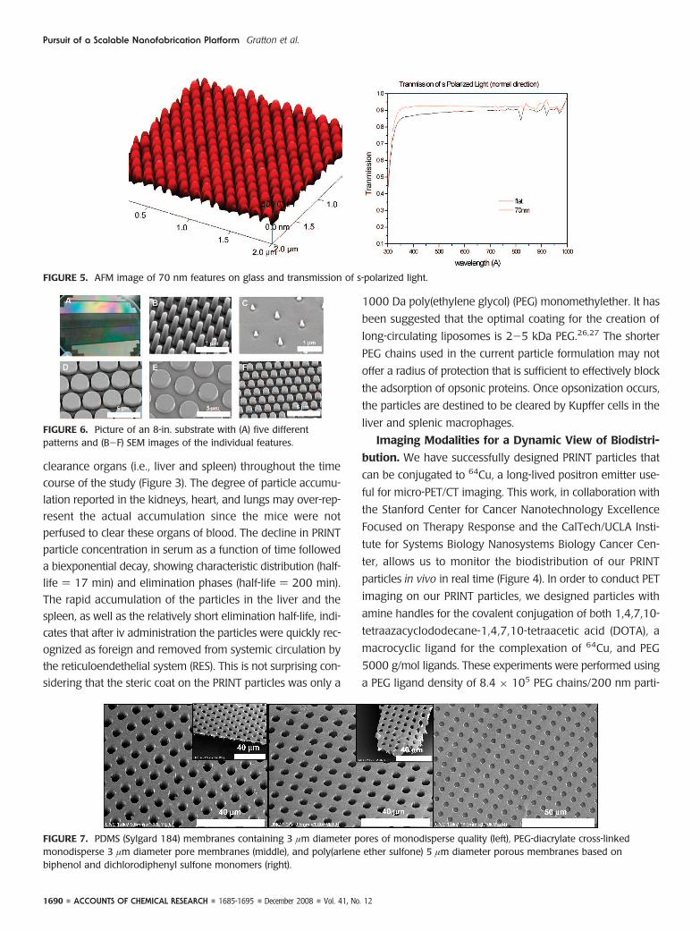
The ability to replicate biological structures may provide
crucial insight into the importance of shape in biology and
lead to advantageous new platforms for imaging and immu-
notherapies, particularly if chemical cues can simultaneously
be incorporated with these biologically derived structure. Fig-
ure 9 shows the molding and replication of dispersed aden-
oviruses on a silicon surface. We were successfully able to
replicate the viruses without degradation of the original aden-
ovirus particles, thus further demonstrating the chemical inert-
ness of the PFPE molding process.
Submicrometer Patterning of Inorganic Oxides. We
explicitly use the low surface energy and high gas permeabil-
ity of cross-linked PFPE-based materials to demonstrate the
FIGURE 9. (A) AFM image of an adenovirus master, prepared by depositing adenovirus particles onto a silicon surface (vertical scale ) 100nm), (B) AFM image of a PFPE mold formed from an adenovirus master (vertical scale ) 50 nm), (C) AFM image of a triacrylate/bisphenol Adimethacrylate adenovirus replica (vertical scale ) 100 nm), (D) transmission electron microtomography (TEMT) reconstruction of atriacrylate/bisphenol A dimethacrylate adenovirus replica, and (E) cryo-electron microscopy reconstruction of adenovirus. Reprinted withpermission from ref 9. Copyright 2007 Wiley-VCH.
Pursuit of a Scalable Nanofabrication Platform Gratton et al.
1692 ACCOUNTS OF CHEMICAL RESEARCH 1685-1695 December 2008 Vol. 41, No. 12

chemical inertness of fluoroelastomers and have illustrated the
use of aggressive chemistries during the embossing and PRINT
processes that enable the formation of uniquely patterned,
sub-500 nm size, inorganic oxide materials with potential util-
ity in electronic and optical devices.45-48 A range of oxides
including SnO2, ZnO, ITO (Sn-doped indium oxide), and
BaTiO3 have been formed into arrays with precise control over
size, shape, and composition (see Figure 10). Figure 11 shows
high aspect ratio TiO2 features derived from a sol-gel solu-
tion patterned from a 200 nm × 600 nm PFPE mold on an
ITO coated glass substrate. The patterns are able to be formed
on both insulating (glass) and conducting substrates (ITO and
FTO coated glass slides). It should be noted that when struc-
tures are patterned through a sol-gel method, volume loss
relative to the original template occurs; however the shrink-
age is able to be controlled by varying the initial sol-gel
chemistry and annealing rates. There is much interest in nano-
patterns of titania for use in titania-polymer solar cells, where
a high degree of order and reproducibility is needed to form
the desired ideal bulk heterojunction.49,50
SummaryIn this Account, we have introduced the concept of PRINT, a
powerful new particle molding, pattern generation, and repli-
cation technique that takes advantage of the unique proper-
ties of PFPE elastomeric molds. The low surface energy
perfluoropolyether network allows for the production of
monodisperse, shape-specific micro- and nanoparticles from
an extensive array of precursors and the generation of high-
fidelity patterns for a wide variety of materials applications.
This work was carried out by a group of outstanding students
and postdoctoral fellows. We would like to thank our co-work-
ers who have made significant contributions to the work
described in this Account, including Charlene M. Ross, Moo
J. Cho, Joseph L. Templeton, and Rudolf Juliano. The authors
would like to acknowledge the collaboration between the Caro-
lina Center of Cancer Nanotechnology Excellence, the Stanford
Center for Cancer Nanotechnology Excellence Focused on Ther-
apy Response, and the CalTech/UCLA Institute for Systems Biol-
ogy Nanosystems Biology Cancer Center, specifically Hsian-
Rong Tseng, Anna Wu, and Michael Phelps for their hard work
towards the PET/CT project. This work was supported in part by
the STC Program of the NSF (Grant CHE-9876674), NIH Grant
P01-GM59299, NIH Grant U54-CA119343 (the Carolina Cen-
ter of Cancer Nanotechnology Excellence), NIH Grant U54-
CA119367 (Stanford Center for Cancer Nanotechnology
Excellence - Therapy Response), NIH Grant U54-CA119347
(CalTech/UCLA Institute for Systems Biology Center Nanosys-
tems Biology Cancer Center), and the William R. Kenan Profes-
sorship of the University of North Carolina at Chapel Hill and
through a sponsored research agreement with Liquidia
Technologies.
BIOGRAPHICAL INFORMATION
Stephanie E. A. Gratton is pursuing her Ph. D. under the super-vision of Dr. Joseph M. DeSimone where she is focused on nano-particles for therapeutic and imaging applications.
Stuart S. Williams is a Ph.D. candidate in Chemistry at the Uni-versity of North Carolina at Chapel Hill under the direction of Dr.Joseph DeSimone. His research focuses on nanopatterning andcontrolling the nanoscale morphology of materials specifically forapplications in optics and photovoltaics.
Mary Napier received her B.S. in chemistry from the Universityof Illinois and her Ph.D. in chemistry from Northwestern Univer-sity under the direction of Peter Stair and was a postdoctoral asso-ciate at Harvard University under the direction of Cynthia Friend.
FIGURE 10. Arrays of features on glass made from a 200 nm ×200 nm mold in (A) SnO2, (B) ZnO, (C) ITO, and (D) BaTiO3.Reprinted with permission from ref 48. Copyright 2008 Wiley-VCH.
FIGURE 11. Array of 200 nm × 600 nm anatase TiO2 features.Reprinted with permission from ref 48. Copyright 2008 Wiley-VCH.
Pursuit of a Scalable Nanofabrication Platform Gratton et al.
Vol. 41, No. 12 December 2008 1685-1695 ACCOUNTS OF CHEMICAL RESEARCH 1693

She is currently a senior research associate at the University ofNorth Carolina in Joseph DeSimone’s laboratory.
Patrick D. Pohlhaus is currently working at LiquidiaTechnologies.
Zhilian Zhou is currently working at Liquidia Technologies.
Kenton B. Wiles is currently a Visiting Professor at Winston-Sa-lem State University in the Department of Chemistry.
Benjamin Mayor is currently is a principal scientist at LiquidiaTechnologies.
Clifton Shen is an adjunct assistant professor at UCLA.
Tove Olafsen is a postdoctoral fellow at the Crump Institute forMolecular Imaging in the Department of Molecular and MedicalPharmacology at UCLA.
Edward T. Samulski is currently the Cary C. Boshamer Profes-sor of chemistry at UNC-CH. Samulski is also a cofounder of Liq-uidia Technologies and is helping to commercialize the PRINTtechnology in material science applications.
Joseph M. DeSimone is currently the Chancellor’s Eminent Pro-fessor of chemistry at UNC-CH and William R. Kenan Jr. Distin-guished Professor of chemical engineering at North Carolina StateUniversity. DeSimone recently launched Liquidia Technologies,along with former members of his laboratory, to commercializethese recent breakthroughs from his laboratory for use in micro-and nanofluidics, soft lithography, and nanofabrication of colloi-dal particles and displays.
FOOTNOTES
*Corresponding author. E-mail: [email protected].
REFERENCES1 Xia, Y. N.; Rogers, J. A.; Paul, K. E.; Whitesides, G. M. Unconventional methods for
fabricating and patterning nanostructures. Chem. Rev. 1999, 99 (7), 1823–1848.2 Chou, S. Y.; Krauss, P. R.; Renstrom, P. J. Imprint lithography with 25-nanometer
resolution. Science 1996, 272 (5258), 85–87.3 Gates, B. D.; Xu, Q. B.; Stewart, M.; Ryan, D.; Willson, C. G.; Whitesides, G. M. New
approaches to nanofabrication: Molding, printing, and other techniques. Chem. Rev.2005, 105 (4), 1171–1196.
4 Xia, Y. N.; Whitesides, G. M. Soft lithography. Angew. Chem., Int. Ed. 1998, 37 (5),551–575.
5 Whitesides, G. M.; Ostuni, E.; Takayama, S.; Jiang, X. Y.; Ingber, D. E. Softlithography in biology and biochemistry. Annu. Rev. Biomed. Eng. 2001, 3, 335–373.
6 Lee, J. N.; Park, C.; Whitesides, G. M. Solvent compatibility ofpoly(dimethylsiloxane)-based microfluidic devices. Anal. Chem. 2003, 75 (23),6544–6554.
7 Rolland, J. P.; Hagberg, E. C.; Denison, G. M.; Carter, K. R.; DeSimone, J. M. High-resolution soft lithography: Enabling materials for nanotechnologies. Angew. Chem.,Int. Ed. 2004, 43 (43), 5796–5799.
8 Rolland, J. P.; Van Dam, R. M.; Schorzman, D. A.; Quake, S. R.; DeSimone, J. M.Solvent-Resistant Photocurable “Liquid Teflon” for Microfluidic Device Fabrication.J. Am. Chem. Soc. 2004, 126, 2322–2323.
9 Maynor, B. W.; Larue, I.; Hu, Z.; Rolland, J. P.; Pandya, A.; Fu, Q.; Liu, J.; Spontak,R. J.; Sheiko, S. S.; Samulski, R. J.; Samulski, E. T.; DeSimone, J. M.Supramolecular nanomimetics: Replication of micelles, viruses, and other naturallyoccurring nanoscale objects. Small 2007, 3 (5), 845–849.
10 Euliss, L. E.; DuPont, J. A.; Gratton, S.; DeSimone, J. Imparting size, shape, andcomposition control of materials for nanomedicine. Chem. Soc. Rev. 2006, 35 (11),1095–1104.
11 Rolland, J. P.; Maynor, B. W.; Euliss, L. E.; Exner, A. E.; Denison, G. M.; DeSimone,J. M. Direct fabrication and harvesting of monodisperse, shape-specificnanobiomaterials. J. Am. Chem. Soc. 2005, 127 (28), 10096–10100.
12 Xia, Y. N.; Whitesides, G. M. Soft lithography. Annu. Rev. Mater. Sci. 1998, 28,153–184.
13 Barenholz, Y. Liposome application: Problems and prospects. Curr. Opin. ColloidInterface Sci. 2001, 6 (1), 66–77.
14 Duncan, R. The dawning era of polymer therapeutics. Nat. Rev. Drug Discovery2003, 2 (5), 347–360.
15 Chien, S. Red-cell deformability and its relevance to blood-flow. Annu. Rev. Physiol.1987, 49, 177–192.
16 Gratton, S. E. A.; Ropp, P. A.; Pohlhaus, P. D.; Luft, J. C.; Madden, V. J.; Napier,M. E.; DeSimone, J. M. The effect of particle design on cellular internalizationpathways. Proc. Natl. Acad. Sci. U.S.A. 2008, in press.
17 Champion, J. A.; Mitragotri, S. Role of target geometry in phagocytosis. Proc. Natl.Acad. Sci. U.S.A. 2006, 103 (13), 4930–4934.
18 Rejman, J.; Oberle, V.; Zuhorn, I. S.; Hoekstra, D. Size-dependent internalization ofparticles via the pathways of clathrin- and caveolae-mediated endocytosis. Biochem.J. 2004, 377, 159–169.
19 Zauner, W.; Farrow, N. A.; Haines, A. M. R. In vitro uptake of polystyrenemicrospheres: Effect of particle size, cell line and cell density. J. Controlled Release2001, 71 (1), 39–51.
20 Harush-Frenkel, O.; Debotton, N.; Benita, S.; Altschuler, Y. Targeting ofnanoparticles to the clathrin-mediated endocytic pathway. Biochem. Biophys. Res.Commun. 2007, 353 (1), 26–32.
21 Gary, D. J.; Puri, N.; Won, Y. Y. Polymer-based siRNA delivery: Perspectives on thefundamental and phenomenological distinctions from polymer-based DNA delivery.J. Controlled Release 2007, 121 (1-2), 64–73.
22 Oupicky, D.; Konak, C.; Ulbrich, K.; Wolfert, M. A.; Seymour, L. W. DNA deliverysystems based on complexes of DNA with synthetic polycations and theircopolymers. J. Controlled Release 2000, 65 (1-2), 149–171.
23 Conner, S. D.; Schmid, S. L. Regulated portals of entry into the cell. Nature 2003,422 (6927), 37–44.
24 Oupicky, D.; Konak, C.; Ulbrich, K.; Wolfert, M. A.; Seymour, L. W. DNA deliverysystems based on complexes of DNA with synthetic polycations and theircopolymers. J. Controlled Release 2000, 65 (1-2), 149–171.
25 Gratton, S. E. A.; Pohlhaus, P. D.; Lee, J.; Guo, J.; Cho, M. J.; DeSimone, J. M.Nanofabricated particles for engineered drug therapies: A preliminary biodistributionstudy of PRINT (TM) nanoparticles. J. Controlled Release 2007, 121 (1-2), 10–18.
26 Moghimi, S. M.; Hunter, A. C.; Murray, J. C. Long-circulating and target-specificnanoparticles: Theory to practice. Pharmacol. Rev. 2001, 53 (2), 283–318.
27 Owens, D. E.; Peppas, N. A. Opsonization, biodistribution, and pharmacokinetics ofpolymeric nanoparticles. Int. J. Pharm. 2006, 307 (1), 93–102.
28 Huang, Y. Y.; Paloczi, G. T.; Yariv, A.; Zhang, C.; Dalton, L. R. Fabrication andreplication of polymer integrated optical devices using electron-beam lithographyand soft lithography. J. Phys. Chem. B 2004, 108 (25), 8606–8613.
29 Menard, E.; Meitl, M. A.; Sun, Y. G.; Park, J. U.; Shir, D. J. L.; Nam, Y. S.; Jeon, S.;Rogers, J. A. Micro- and nanopatterning techniques for organic electronic andoptoelectronic systems. Chem. Rev. 2007, 107 (4), 1117–1160.
30 Ziebarth, J. M.; Saafir, A. K.; Fan, S.; McGehee, M. D. Extracting light from polymerlight-emitting diodes using stamped Bragg gratings. Adv. Funct. Mater. 2004, 14(5), 451–456.
31 Quake, S. R.; Scherer, A. From micro- to nanofabrication with soft materials.Science 2000, 290 (5496), 1536–1540.
32 Xia, Y. N.; Kim, E.; Zhao, X. M.; Rogers, J. A.; Prentiss, M.; Whitesides, G. M.Complex optical surfaces formed by replica molding against elastomeric masters.Science 1996, 273 (5273), 347–349.
33 Zhou, Z. R., G.; Mar, D.; Meng, X.; Orr, J.; Henn, R. Low cost manufacturing ofpatterned films with nano-precision. Dig. Tech. Pap. Soc. Inf. Disp. Inf. Symp. 2008,37, 534–536.
34 Boyle, T. J.; Brinker, C. J.; Gardner, T. J.; Sault, A. G.; Hughes, R. C. Catalyticmembrane sensors. A thin film modified H-2 resistive sensor for multi-moleculardetection. Comments Inorg. Chem. 1999, 20 (4-6), 209–231.
35 Hedrick, J. L.; Miller, R. D.; Hawker, C. J.; Carter, K. R.; Volksen, W.; Yoon, D. Y.;Trollsas, M. Templating nanoporosity in thin-film dielectric insulators. Adv. Mater.1998, 10 (13), 1049–1053.
36 Huo, Q. S.; Zhao, D. Y.; Feng, J. L.; Weston, K.; Buratto, S. K.; Stucky, G. D.;Schacht, S.; Schuth, F. Room temperature growth of mesoporous silica fibers: Anew high-surface-area optical waveguide. Adv. Mater. 1997, 9 (12), 974–978.
37 Lu, Y. F.; Fan, H. Y.; Doke, N.; Loy, D. A.; Assink, R. A.; LaVan, D. A.; Brinker, C. J.Evaporation-induced self-assembly of hybrid bridged silsesquioxane film andparticulate mesophases with integral organic functionality. J. Am. Chem. Soc. 2000,122 (22), 5258–5261.
Pursuit of a Scalable Nanofabrication Platform Gratton et al.
1694 ACCOUNTS OF CHEMICAL RESEARCH 1685-1695 December 2008 Vol. 41, No. 12

38 Echigo, Y.; Iwaya, Y.; Saito, M.; Tomioka, I. A novel preparative method ofmicroporous poly(4,4′-oxydiphenylenepyromellitimide) membranes. Macromolecules1995, 28 (19), 6684–6686.
39 Odom, D. J.; Baker, L. A.; Martin, C. R. Solvent-extraction and Langmuir-adsorption-based transport in chemically functionalized nanopore membranes. J.Phys. Chem. B 2005, 109 (44), 20887–20894.
40 Hedrick, J. L.; Carter, K.; Sanchez, M.; DiPietro, R.; Swanson, S.; Jayaraman, S.;McGrath, J. G. Crosslinked polyimide foams derived from poly(imide-propyleneoxide) copolymers. Macromol. Chem. Phys. 1997, 198 (2), 549–559.
41 Hedrick, J. L.; Charlier, Y.; DiPietro, R.; Jayaraman, S.; McGrath, J. E. High T-gpolyimide nanofoams derived from pyromellitic dianhydride and 1,1-bis(4-aminophenyl)-1-phenyl-2,2,2-trifluoroethane. J. Polym. Sci., Part A: Polym. Chem.1996, 34 (14), 2867–2877.
42 Wiles, K.; B, W., N. S.; Herlihy, K. P.; Maynor, B. W.; Rolland, J. P.; DeSimone, J. M.Soft lithography using perfluorinated polyether molds and print technology forfabrication of 3-D arrays on glass substrates. Proc. Int. Soc. Opt. Eng. 2006, 6151–119.
43 LaRue, I.; Adam, M.; Pitsikalis, M.; Hadjichristidis, N.; Rubinstein, M.; Sheiko, S. S.Reversible morphological transitions of polystyrene-b-polyisoprene micelles.Macromolecules 2006, 39 (1), 309–314.
44 Brands, M.; Carl, A.; Dumpich, G. Preparation of large area sub-50 nm polymernanoring arrays. Superlattices Microstruct. 2005, 37 (6), 388–393.
45 Xia, D. Y.; Li, D.; Ku, Z. Y.; Luo, Y.; Brueck, S. R. J. Top-down approaches to theformation of silica nanoparticle patterns. Langmuir 2007, 23 (10), 5377–5385.
46 Yang, P.; Yang, M.; Zou, S. L.; Xie, J. Y.; Yang, W. T. Positive and negative TiO2
micropatterns on organic polymer substrates. J. Am. Chem. Soc. 2007, 129 (6),1541–1552.
47 Ravirajan, P.; Peiro, A. M.; Nazeeruddin, M. K.; Graetzel, M.; Bradley, D. D. C.;Durrant, J. R.; Nelson, J. Hybrid polymer/zinc oxide photovoltaic devices withvertically oriented ZnO nanorods and an amphiphilic molecular interface layer. J.Phys. Chem. B 2006, 110 (15), 7635–7639.
48 Hampton, M. J.; W, S. S.; Zhou, Z.; Nunes, J.; Ko, D. H.; Templeton, J. L.; Samulski,E. T.; DeSimone, J. M. The patterning of sub-500nm, inorganic oxide structuresusing crosslinked perfluoropolyethers. Adv. Mater. 2008, 20, 2667–2673.
49 Coakley, K. M.; McGehee, M. D. Conjugated polymer photovoltaic cells. Chem.Mater. 2004, 16 (23), 4533–4542.
50 Watkins, P. K.; Walker, A. B.; Verschoor, G. L. B. Dynamical Monte Carlo modellingof organic solar cells: The dependence of internal quantum efficiency onmorphology. Nano Lett. 2005, 5 (9), 1814–1818.
Pursuit of a Scalable Nanofabrication Platform Gratton et al.
Vol. 41, No. 12 December 2008 1685-1695 ACCOUNTS OF CHEMICAL RESEARCH 1695