Embed Size (px)
Citation preview

f! :;;
:•
' f
' -
. -' . . :-1
r -r r
~
I
National Academy
of -Sciences
-National Research Council I~
- - --- -----\
NUCLIAR· SCIENCE SERIES
_The Radiochemistry of the Rare Gases
COMMITTEE ON NUCLEAR SCIENCE
L.F.CURTIEIS,CllainflM National Bureau of Standard&
ROBLEY D. EVANS, Vke CMIPWlllll Mu11aohwMttta Inlltltute of Tec!moloBY
J, A. DeJDREN, S.CY11tary WHtlngbowie Eleotrlc Corporation
C. J. BORKOWSKI Oak Ridge Nadona.l Laboratory
ROBERT G. COCHRAN Tuaa Agricultural and Mechanical
College
SAMUEL EPSTEIN Callfornla hultltute of Teolmology
U.P'ANO National Bureau of Btandarda
HEB.BERT GOLDSTEIN Nuclear Development Corporation of
Amertoa
J. w. mvnra, JR. Mull&Chuaeua IDaUtuai al. Teo.lm.oloU"
E. D.KLEMA Northwestern University
W. WAYNE MEINKE Un1ver11lty of Mt.chlpn
J. J. NICKSON llem.ortal Hoap:l.tal, New York
ROBERT L. PLATZMAN Laboratoire de Ch1m1e Pbyldque
D.11. VAN PATrER Bartol Ra11earoh FOUlldatlon
LIAISON MEMBERS.
PAUL C. AEBERSOLD Atomlo Energy CommlHlon
J. HOW ARD MoMILLEN National Bolence Foundation
CHARLES K. REED U. s. Air Force
WILLIAM E. WRIGHT Offtce of NB.VIII Raaearoh
SUBCOMMITIEE ON RADIOCHEMISTRY
W. WAYNE MEINKE, Clun"""71 Univenlty of Michigan
GREGORY B.. CHOPPIN Flortcl.a State University
GEORGE A. COWAN Loa AlamOll BclentHlo Laboratory
ARTHUR W. FAIRHALL Vnlver11lty of Wublngton
JEB.OMJC HUDIB Brookhaven National Laboratory
EARL HYDE University of California (Berkeley)
HAROLD KIRBY Mound Laboratory
GEORGE LEDDICOTI"E Oak Ridge National Laboratory
.JULIAN NIELSEN Buford Laboratorte11
ELLIS P. STEINBERG Argonne National Laborlltory
PETER C. STEVENSON University of Callfornla (Livermore)
LEO YAFFE McGlll Univeralty
CONSULTANl'S
NA THAN BALLOU Centre d'Etuae de l'Enerpe Nucleaire
Mol-Donk, Belgium
JAMESDeVOE University of Mlchipn
Wll.LIAJI MAB.LOW National Bureau of Standards
. CHDOSTRY
The Radiochemistry of. the Rare Gases
i O> O>
~co·
i~i co
....... (¥) ·-(¥) -0>
. ==(¥).
By FLOYD F. MOllYBR, JR.
Lawerui11 Ratffatlm& Laboratory lhliwtnlty of CaUjrJnda Llvermor11. CaHjonda
Ootober 1880
.APR - 6 19Si
L]BR.ARIE$ PROPERTY
·11-,.. .. ,•I
• . -·. ·- _ . __ .. . Subcommittee OD Radl.ochemiatry Nalloaal Academy of Sclpcee-Nalloaal Research Coan.ell
PrlDtltd ID UM. Prtoe .0. 71. A'ftilable from U. Oftloe ol. Teolmical llento8•, Depu1mMlt of c-m.roe, WUbDStaD II, D. C •.
FOREWORD.
The Subcommittee on Radiochemistry is one o~ a number of subcommittees working under the Committee on Nuclear Science within the National Academy of Sciences - National Research Council. Its members represent government, industrial, and university laboratories 1n the areas of nuclear chemistry and analytical chemistry
The Subcommittee has concerned itself with those areas of nuclear science which involve the chemist, such as the collection and distribution of radiochemical procedures, the establishment of specifications for radiochemically pure reagents, availability of cyclotron time for service irradiations, the place of radiochemistry in the undergraduate college program, etc. ··
Thie series of monographs has grown out of the need for up-to-date compilations of raO.iochemical information and procedures. The Subcommittee has endeavored to present a aeries which will be of maximum use to the working scientist and which contains the latest available information. Ee.ch monograph collects in one volwne.the pertinent information required for radiochemical work with an individual element or a group of closely related elements.
An expert in the radiochemistry of the particular element has written the monograph, following a standard format developed by the Subcommittee. The Atomic'Energy Commission has sponsored the printing of the series.
The Subcommittee is confident these publications will be useful not only to the radiochemist but also to the research worker 1n other fields such as physics, biochemistry or medicine who wishes to use radiochemical techniques to solve a specific problem.
iii
w. Wayne Meinke, Chairman Subcommittee on Radiochemistry
INTRODUCTION
This report dealing with the radiochemistry of the rare gases was pre
pared at the request of the Subcommittee on Radiochemistry of the Committee
on Nuclear Science of the National Research Council as one of a series of
monographs on the radiochemistry of all the elements.
The early sections of this monograph are devoted to general reviews of
rare gas properties of interest to the radiochemist and to some general dis -
cussion of separation techniques for rare gases. The last three chapters are
respectively a discussion of the removal of rare gases from targets, a dis
cussion of techniques used for counting radioactive rare gases, and a collec
tion of radiochemical procedures for rare gas es.
The author would appreciate receiving from readers. any additional in
formation, published or unpublished, which should be included in such a report
on the radiochemistry of the rare gases.
The author takes this opportunity to acknowledge the a.ble assistance of
Mr. R. A. daRoza in the preparation of this monograph.
iv
CONTENTS
Foreword iii
Introduction iv
I. General References Pertinent to ~are Gas Radiochemistry 1
II. Table of Isotopes of He, Ne, A, Kr, Xe, and Rn z
III. Review of Features of Interest in Rare Gas Radiochemistry 5
IV. Sample Solution and Exchange with Carriers Z7
V. Counting Rare Gas Activities Z9
VI. Collection of Radiochemical Procedures for the Rare Gases 34
Procedure l - Removal of Kr and Xe from Air and
Their Subsequent Separation 34
Procedure l A - Removal and Separation of Kr and Xe Z35
Fission Products from U Targets 40
Procedure Z - The Extraction, Purification and
Industrial Uses of Kr 85 43
Procedure 3 - Rapid Removal of Fission Product
Kr from U Foil 46
Procedure 4 - Recovery of Fission Product Xe
from U Metal 46
Procedure 5 - Rapid Removal of Fission Product Xe
from uo3 or UOz (N03 >z · 6 HzO Targets 48
Procedure 6 - Separation of Long-lived Fission Gases 48
Procedure 7 - Removal of Rn from Th Targets and its
Collection on the Cathode of a Discharge
T~e ~
Procedure 8 - Determination of Active Gas Half-lives
by the Charged Wfre Technique (II) 51
v
The Radiochemistry of the Rare Gases
FLOYD F. MOMYER, JR. Lawrence Radiation Laboratory
University of California Livermore, California
I. GENERAL REFERENCES PERTINENT TO RARE GAS RADIOCHEMISTRY
H. Remy, Treatise on Inorganic Chemistry, Vol.I (translated by J. S.
Anderson), Elsevier Publishing Co., New York (1.956).
S. Dushman, Vacuum Technique, John Wiley and Sons, New York, 1949.
R. T. Sanderson, Vacuum Manipulation of Volatile Compounds, John
Wiley and Sons Inc., New York (1948).
R. E. Dodd and P. L. Robinson, Experimental Inorganic Chemistry
Chap. 2, Elsevier Publishing Co., New York (1954).
S. Brunauer, The Adsorption of Gases and Vapors, VQ.l. .I. 11 Physical
Adsorption", Princeton University Press, Princeton, N. J. (1942).
A. I. M. Keulemans, Gas Chromatography, Reinhold Publishing Co.,
New York, 1959, 2nd edition.
Lawrence A. Weller, "The Adsorption of Krypton and Xenon on Activated
Charcoal - - A Bibliography, 11 Mound Laboratory ~eport Mi..M-1092,
Miamisburg, Ohio, 1959.
A. Guthrie and R. K. Wakerling, editors, Vacuum Equipment and Tech
niques, National Nuclear Energy Series, Div. I, Vol. 1, McGraw-Hill
Book Co., Inc., New York, 1949.
C. D. Coryell and N. Sugarman, editors, Radiochemical Studies: The
Fission Products, National Nuclear Energy Series, Div. IV, Vol. 9.
~ooks 2 and 3, McGraw-Hill·Book Co., Inc., New York, 1951. Papers
64-70, 139, 141, 145-50, 154, and 311-17.
l.
Isotope
He4
He6
Nel8
Nel9
Nezo
NeZl
Nezz
NeZ3
A4Z
~r76
Kr77
Kr 78
Kr 79
Kr80
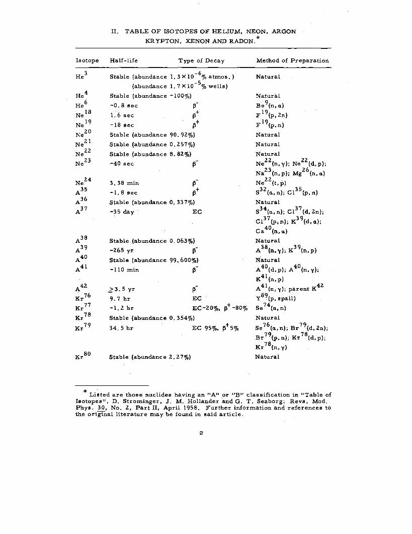
II. TABLE OF ISOTOPES OF HELIUM, NEON, ARGON
KRYPTON, XENON AND RADON.*
Half-life Type of Decay
Stable (abundance -4
1. 3 X l 0 % atmos.)
(abundance
Stable (abundance
-0.8 sec
-5 1.7Xl0 %wells)
1. 6 sec
-18 sec
-100%)
13-13 +
13+ Stable (abundance 90. 9Z%)
Stable (abundance 0. Z57%)
Stable (abundance 8. 8Z%)
-40 sec
3. 38 min
-1.8 sec
13-
Stable (abundance 0. 33 7%)
-35 day EC
Stable (abundance 0. 063%)
-Z65 yr
Stable (abundance 99. 600%) --110 min 13
-..? 3. 5 yr 13 9. 7 hr EC
-1. Z hr EC-ZOo/o,
Stable (abundance 0. 354%)
13+ -80%
+ 34. 5 hr EC 95%, 13 5%
Stable (abundance Z. Z 7%)
Method of Preparation
Natural
Natural
Be 9(n, a)
F 19(p,Zn)
Fl9(p, n)
Natural
Natural
Natural zz zz
Ne (n,y); Ne (d,p); Z3 26
Na (n, p); Mg (n, a) zz .
Ne (t, p) 3Z 35 S (a, n); Cl (p, n)
Natural 34 37
S (a, n); Cl (d; Zn}; 37 39 Cl (p, n); K (d, a); 40
Ca (n, a)
Natural 38 39 A (n,y); K (n,p)
Natural 40 40 A (d, p); A (n, y);
K41(n, p) 41 4Z
A (n, y); parent K
y 89(p, spall)
Se 74
(a, n)
Natural 76 79 Se (a, n); Br (d, Zn); 79 78 Br (p, n); Kr (d, p); 78
Kr (n, y)
Natural
* . Listed are those nuclides having an "A" or "B" classification in "Table of
Isotopes", D. Strominger, J. M. Hollander and G. T. Seaborg: Revs. Mod. Phys. 30, No. Z, Part II, April 1958. Further information and references to the original literature may be found in said article.
2
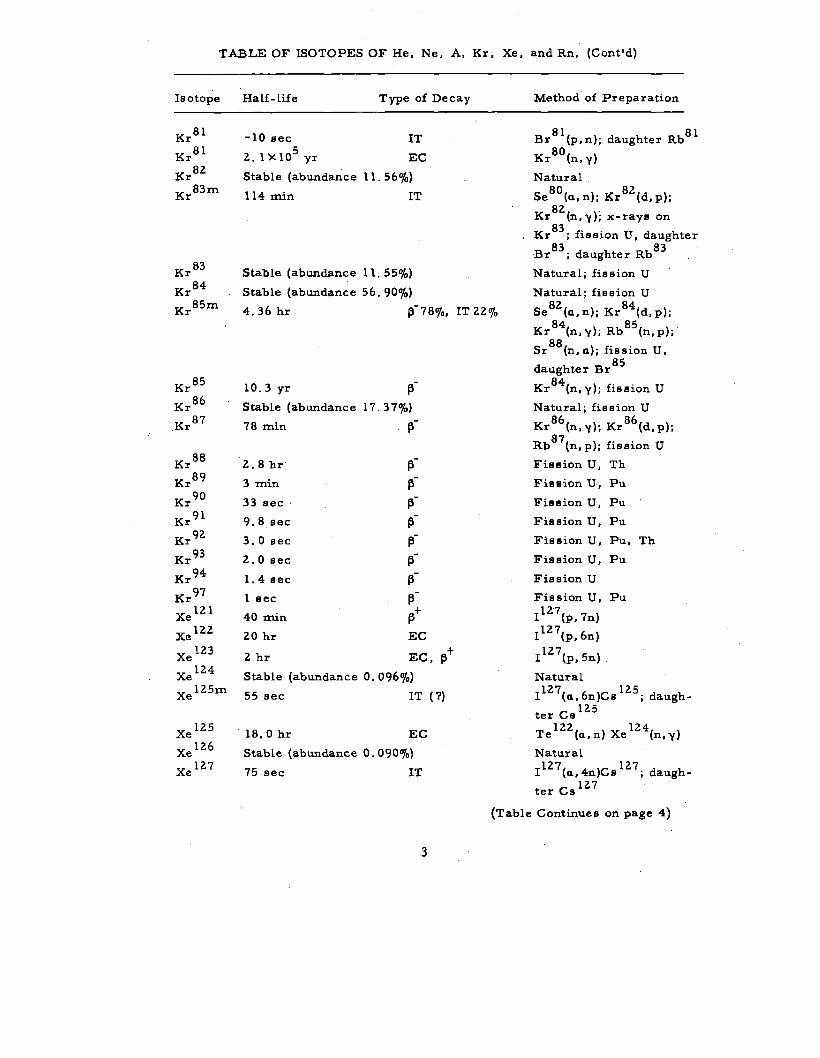
TABLE OF ISOTOPES OF He, Ne, A, Kr, Xe, and Rn, (Cont'd)
Isotope
Kr81
Kral
Kr82
Kr83m
Kr83
Kr84
Kr8Sm
Kras
Kr86
Kr87
Kras
Kr89
Kr 90
Kr 91
Kr92
Kr93
Kr94
Kr97
Xe121
Xel22
Xel23
Xel24
Xe 12Sm
Xel2S
Xel26
Xel27
Half-life Type of Decay
-10 sec IT s
2.. lXlO yr EC
Stable (abundan:ce 11. S6%)
114 min IT
Stable (abundance 11. SS%)
Stable (abundance S6. 90%)
Method of Preparation
81 81 Br (p, n); daughter Rb
80 Kr (n,y)
Natural . 80 82
Se (a., n); Kr (d, p); 82.
Kr (n, y); x-rays on
Kr83
; fission U, daughter 83 83
Br ; cj.aughter Rb
Natural; fission U
Natural; fission U
4. 36 hr ~-78%, IT 22% 82 84 Se (a., n); Kr (d, p);
10. 3 yr 13 -Stable (abundance 17. 37%)
78 min ~-
2. 8 hr 13-3 min 13-
-33 sec 13 -
9. 8 sec 13 3.0sec 13-
-2. 0 sec 13 -1. 4 sec 13 -l sec 13
40 min ~+
20 hr EC
2 hr EC, 13+ Stable (abundance 0. 096%)
SS sec IT (?)
18. 0 hr EC
Stable (abundance 0. 090%)
7S sec IT
3
84 8S Kr (n,y); Rb (n,p);
Sr88
(n, a.); fission U, 8S
daughter Br
Kr 84(n, y); fission U
Natural; fission U 86 86
Kr (n,y);Kr (d,p);
Rb87
(n, p); fission U
Fission U, Th
Fission U, Pu
Fission U, Pu
Fission U, Pu
Fission U, Pu, Th
Fission U, Pu
Fission U
Fission U, Pu
I12·7(p, 7n)
Il27(p, 6n)
Il27(p, Sn)
Natural 127 12S
I (a., 6n)Cs ; daugh-
ter Cs 12 S 122 . 124
Te (a., n) Xe (n, y)
Natural 127 127
I (a., 4n)Cs ; daugh-
ter Cs l2. 7
(Table Continues on page 4)
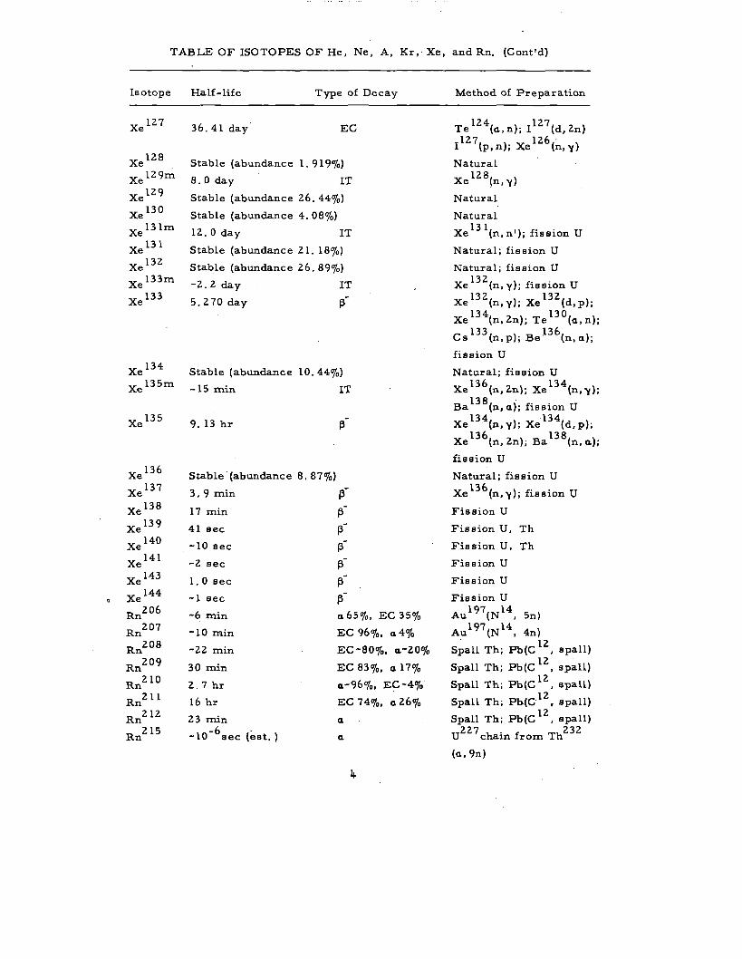
TABLE OF ISOTOPES OF He, Ne, A, Kr, Xe, and Rn. (Cont'd)
Isotope
Xel27
Xel28
Xe 129m
Xel29
Xel30
Xe 13 lm
Xel31
Xe132
Xe 133m
Xe 133
Xe 134
Xe 135m
Xel35
Xe 136
Xe 137
Xe 138
Xel39
Xe 140
Xe 141
Xe 143
Xe 144
RnZ06
RnZ07
RnZ08
RnZ09
Rnz 10
Rnz 11
Rnz lZ
RnZ.15
Half-Life Type of Decay
36. 41 day EC
Stable (abundance 1. 919"/o)
8. 0 day IT
Stable (abundance 26. 44"/o)
Stable (abundance 4. 08"/o)
lZ.Oday IT
Stable (abundance Z 1. 18"/o)
Stable (abundance Z6. 89%)
-z.z day IT
5. Z 7 0 day 13-
Stable (abundance 10. 44"/o)
-15 min IT
-9. 13 hr 13
Stable (abundance 8, 87"/o)
3. 9 min 13--17 min 13
41 sec J3 --10 sec J3 --z sec J3 -1. 0 sec 13-
--1 sec J3 -6 min a.65"/o, EC 35"/o
-10 znin EC 96"/o, a.4%
-zz min EC-80"/o, a.-ZO"/o
30 min EC 83"/o, a. 17%
Z.. 7 hr a.-96%, EC-4"/o
16 hr EC 74"fo, a. Z.6%
Z3 min a. -6 .
-10 sec (est.) a.
4
Method of Preparation
Te 124(a., n); Il27 (d, Zn) 1Z7 1Z6 .
I (p, n); Xe (n, y)
Natural 1Z8 Xe (n,y)
Natural
Natural
Xe 131
(n, n'); fission U
Natural; fission U
Natural; fission U
Xe 13 Z(n, y); fission U 13Z 13Z Xe (n,y); Xe (d,p); 134 130
Xe (n, Zn); Te (a., n); 133 136 Cs (n,p); Be (n,a.);
fission U
Natural; fission U 136 134 Xe (n,Z.n); Xe (n,y);
B 138( >" f" . u a n, a. ; 1SS1on 134 134
Xe ·(n,y);Xe (d,p); 136 138
Xe (n, Zn); Ba (n, a.);
fission U
Natural; fission U
Xe 136 (n, y); fission U
Fission U
Fission U, Th
Fission U, Th
Fission U
Fission U
Fission U
Aul97(Nl4, Sn)
Au197(Nl4, 4n) . lZ
Spall Th; Pb(C , spall) lZ
Spall Th; Pb(C , spall)
Spall Th; Pb(C lZ, spall}
Spall Th; Pb(C12
, spall) lZ
Spall Th; Pb(C , spall)
Uzz 7 chain from Th23 z
(a., 9n)
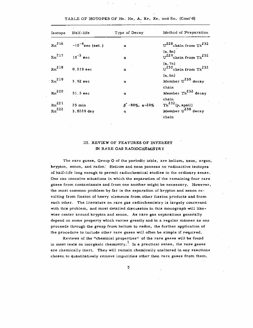
TABLE OF ISOTOPES OF He, Ne, A, Kr, Xe, and Rn, (Cont'd)
Isotope
Rn216
Rn217
Rn218
Rn219
Rn220
Rn221
Rn222
Half-life Type of Decay Method of Preparation
-10-4 sec (est. ) a. u228chain from Th
232
(a., Sn) -3 u229
chain from Th232 10 sec a.
(a., 7n)
0.019sec a. u230chain from Th
232
(a., 6n)
3. 92 sec Member 235
a. U decay
chain
51. 5 sec Member 232
a. Th decay
chain
25 min 13 - -80%, a.-20%
232 Th (p, spall)
3. 8229 day Member 238
a. U decay
··chain
III. REVIEW OF FEATURES OF INTEREST
IN RA RE GAS RADIOCHEMISTRY
The rare gases, Group 0 of the periodic table, are helium, neon, argon,
krypton, xenon, and radon.' Helium and neon possess no radioactive isotopes
of half-life long enough to permit radiochemical studies in the ordinary sense.
One can conceive situations in which the separation of the remaining four rare
gases from contaminants and from one another might be necessary. However,
the most common problem by far is the separation of krypton and xenon re -
sulting from fission of heavy elements from other fission products and from '
each other. The literature on rare gas radiochemistry is largely concerned
with this problem, and most detailed discussion in this monograph will like
wise center around krypton and xenon. As rare gas separations generally
depend on some property which varies greatly and in a regular manner as one
proceeds through the group from helium to radon, the further application of
the procedure to include other rare gases will often be simple if required.
Reviews of the "chemical properties" of the rare gases will be found
in most texts on inorganic chemistry.1. In a practical sense, the rare gases
are chemically inert. They will remain chemically unaltered in any reactions
chosen to quantitatively remove impurities other than rare gases from them.
5
However, rare gas atoms do interact with other atoms,. molecules, or ions in
their neighborhood. Whether these interactions are properly considered
chemical or "van der Waal's" in nature is of no concern here.
The existence in discharges of species such as HeH+ and He2
+ has been
established. Hydrates for the four heavier members of the group are known
to exist, and solubilities of rare gases in a number of solvents are relatively
high. Solubility in a given solvent generally increases with atomic number of
the rare gas. A number of studies of rare gas solubility dependence on sol
vent, temperature, and partial pressure ·of the rare gas (Henry's Law is ap
plicable over· wide ranges) have appeared in the literature. One of the more
comprehensive studies also outlines a proposed system for recovering krypton
and xenon from gas streams by their absorption in a counter-current stream
of organic liquid (kerosene). 2
In handling rare gases, especially tracer amounts, one does well to
'remember that contact with liquids or solids (including system walls) or
condensation from the gas phase of other liquids or solids may result in re
moval of rare gases from the .gas phase through solution, adsorption or phys -
ical occlusion. Thus in quantitative work rare gas carriers are usually added
for essentially 'the same reasons that carriers are added for species to be
separated from solutions.
A series of substances known as clathrates has received considerable 3 4
study. • Clathrates of argon, krypton and xenon have been prepared by
crystallizing quinol under an atmosphere of the rare gas at high pressure.
Rare gas atoms are contained in "cages" within the resulting crystal, .the
number of these cages setting an upper limit on the amount of rare gas in the
crystal (one rare gas atom for every three quinol molecules). The actual
concentration of rare gas in the crystal depends markedly on the conditions of
crystallization and is usually considerably less than the theoretical Limit.
Clathrates of fission-product krypton have recently been prepared for use as
f K BS t" · 5 Th . d . "b d i h f sources o r ac iv1ty. e preparation escr1 e n t e re erence re-
sults in krypton concentrations equal to 25% of the theoretical limit. This
corresponds to the concentration in the gas phase at about 25 atmospheres
pressure and results in 3 curies of Kras. per gram of clathrate (using fission
product krypton which is about 5% Kra 5). The material may be ground to a
powder with no appreciable loss of activity and the loss on standing is only a
few parts per .million. per day if the material is protected from water and
other substances which dissolve quinol.
The chemical operations involved in separating and purifying rare gases
are performed on elements or compounds other than rare gases. The separa
tion of the rare gases from one another must be accomplished on the basis of
differences in some physical property (usually vapor pressure or extent of
6
adsorption). It may often happen that this physical separation will also sepa
rate some or all of the impurities other than rare gases from a particular
rare gas. Thus it is often neither necessary nor most convenient to purify
the rare gases chemically as a group as the first step or steps in a radiochem
ical procedure. Depending upon the contaminating species and their amounts
it may be possible that no chemical operations whatever will be necessary.
Substances which may contaminate rare gases are limited to those which
may exist in appreciable concentrations in the gas phase at the temperature of
the experiinent. At said temperature this will include: 1) gases, the term
_being used here to denote appreciable amounts of substances above their
critical temperature or having vapor pressures greater than 1 atmosphere;
2) unsaturated vapors, substances whose vapor pressures are less than one
atmosphere but which are present in amounts appreciable but small enough
that their partial pressures are less than their vapor pressures; and 3) satu,
rated vapors in equilibrium with solids or liquids having appreciable vapor
pressures. The word "appreciable" in the foregoing must of course be de
fined in the context of the ~xperiment. Although the above is a large category,
the number of contaminants usually encountered is quite small. The rare
gases must ofte~ be purified from the constituents of air, from volatile species
involved in target dissolution such as hydrogen, hydrogen halides and oxides
of nitrogen, and occasionally from small amounts of hydrocarbons and trace
amounts of elemental halogens. Methods of removal are listed below for each
of these. The list is by no means complete as regards methods which have
been or could be used, but it is hoped that it is representative enough to be
useful.
1) Nitrogen: Mole amounts may be quantitatively removed by reacting
with titanium sponge, 14-20 mesh at 1000-l 100°C. Use of lower temperatures
(ca. 850°C) has been reported. 6
Oxygen is also removed quantitatively.
Quartz or ceramic furnaces are necessary as these temperatures are above
the softening point of Pyrex. glasses. The reaction is quite exothermic and
so the temperature must be monitored and flow rate of the gas controlled _to
prevent destruction of the furnace. Calcium has often been used satisfactorily
to remove nitrogen (400-5_00°C). Calcium does, however, tend to become
passive through formation of surface films. For small amounts of impurities
this problem is sometimes circumvented.by conducting the reaction in the gas
phase with Ca vapor. 7
Clean uranium turnings at 800 °C will also react with 8 nitrogen (and decompose hydrocarbons ).
2) Oxygen: Will be removed with nitrogen in the above reactions. Oxy
gen also reacts rapidly with copper turnings above 350°C to give CuO.
3) Hydrogen, carbon monoxide, light pa.raffin hydrocarbons: Passage
7
of the gas stream over CuO at 500 °C will oxidize H2
to H 20 9 and CO to co2 rapidly. Hydrocarbons will be oxidized in like manner to H 20 and COz. but a
temperature of 900°C is necessary to achieve rapid reaction. Subsequent re
moval of oxygen may be necessary (and is easily accomplished), if high enough
temperatures are used that the dissociation pressure of oxygen over CuO becomes
appreciable.
4) Water: In addition to condensation of water in cold. traps (a method
often not specific enough), water may be removed by passage through any one
of a number of desiccants. P 2o5
, Mg(Cl04 )2 ; and CaC12
are representative,
with equilibrium partial pressures of water over them at room temperature -5 -4
of 2 X 10 , 5 x 10 , and 0. 2 mm Hg respectively. P2
o5
and CaC12
rep-
resent the extremes of efficiency in common desiccants. Magnesium per
chlorate has achieved wide use as it is efficient enough for practically all pur
poses and is easily regenerated by distilling the water off in vacuo at 220 °C.
Where large amounts of water are involved, gases are often dried first with
CaC12 to remove most of the water and then with Mg(Cl04
)2 to remove re
maining traces of moisture.
5) Carbon dioxide: May be removed by passing the gas through a trap
containing Ascarite, a granular commercial preparation which is essentially
asbestos impregnated with soditrm hydroxide. Sofnolite, or soda-lime, a
mixture of NaOH and Cao may also be used. Sweeping the gas through a
solution of alkali metal hydroxide is also effective. Solutions are sometimes
less convenient in vacuum systems than solid materials, ·however.
6) Hydrogen halides: May be removed in the same manner as carbon
dioxide.
7) Oxides of nitrogen: Dissolution of targets in nitric acid will result
in evolution of N20, NO and N02 ir.. varying proportions. N 20 usually occurs
in relatively small amounts. Its removal may be accomplished by catalytic
reduction with hydrogen or by oxidation to NO by scrubbing the gas with a
solution of strong oxidizing agent such as permanganate. NO and N02 may
be removed by sweeping the gas stream through a solution of sodium hydrox
ide. Performing the solution under reflux will in fact wash a good portion of
the higher oxides back into the dissolver flask. If alternate methods of solu
tion are available it is often most convenient to avoid the use of nitric acid.
8)· Halogens: Free halogens are all relatively volatile,. and active halo
gens may often be present in trace amounts in targets from which rare gases
are to be removed. If the solution process leaves them partly or entirely in
the zero oxidation state, the gas stream will be contaminated. Sweeping the
gas through a solution of sodium hydroxide will rapidly convert all the free
halogens to non-volatile species (halide and hypohalite). IO The rapid ex
change of the halogens with their corresponding halides in solution is another
8
11 12 useful means of decontamination from tracer halogens. ' Iodine is quan-
titatively removed by contact with silver (silvered Raschig rings have been
used as a trap packing for this purpose). Iodine is reduced to iodide in NaHS03
solution.
Where reaction rates are slow enough that purification may not be com
pleted in one pass, it may be necessary to circulate the offgases from target
dissolution through a purification train. The classic, and still most generally 13
useful, device for circulation (or transfer) of gases is the Toepler pump,
with which rates of about a liter per minute may be obtained. Other circulat
ing pumps which may be useful in particular instances have been designed.
These consist essentially of a chamber designed to permit only unidirectional
flow of gas and a means of producing periodic pressure changes within the
chamber. Alternate heating and cooling of the gas in the chamber has been 13
used to achieve flow rates of 0. 5 liters per hour. An iron piston enclosed
in glass and electromagnetically operated has produced rates of a few liters
pel' minute,14
Pressure differentials developed were. not noted in the reference
but are probably small. Another achieves similarly high flow rates by pulsing
the chamber pressure by means of a mylar diaphragm driven by high pressure 15
gas.
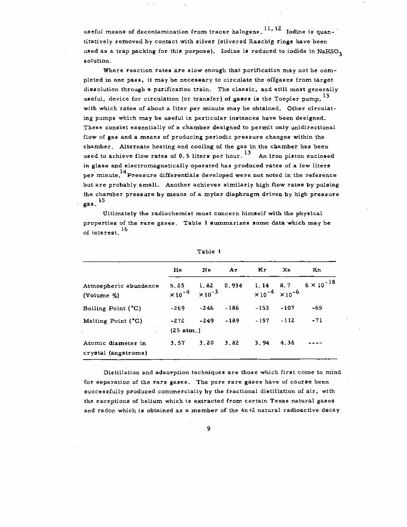
Ultimately the radiochemist must concern himself with the physical
properties of the rare gases. Table l summarizes some data which may be
f . 16
o interest.
Table l
He Ne Ar Kr Xe Rn
Atmospheric abundance 5.25 l. 82 0.934 l. 14 8.7 6XlO-l 8
(Volume %) x 10-4 x 10-3 x 10-4 x io-6
Boiling Point ( °C) -269 -246 -186 -153 -107 -65
Melting Point ( •c) -272 -249 -·189 -157 -112 -71
(25 atm.)
Atomic diameter in 3.57 3.20 3.82 3.94 4.36
crystal (angstroms)
Distillation and adsorption techniques are those which first come to mind
for separation of the rare gases. The pure rare gases have of course been
successfully produced commercially by the fractional distillation of air, with
the exceptions of helium which is extracted from certain Texas natural gases
and radon which is obtained as a member of the 4n+2 natural radioactive decay
9
series. Fractional distillation is discussed in most texts on physical chem
istry and the fractionation of rare gases from air is discussed in numerous
places. l 7-ZO Glueckauf used a procedure combining fractional distillation of
air and adsorption techniques in the determination of krypton and xenon con-21 ..
tents of the atmosphere. It is very Q.Illikely that the radiochemist will have
need to use such low temperature fractionation columns in the laboratory so
there will be no discussion of the method here.
On the other hand, simple distillation and condensation processes will
be used in practically every experiment in transferring gases or effecting
rough separations. Thus a plot ( for low temperatures) of vapor .pressures as
a function of temperature for rare gases and other volatile species commonly'
encountered will prove very handy to the radiochemist. The reader is refer -
red to the generally available Handbook .of Chemi;stry and Physics22
for data 23
necessary for such a plot. Dushman (page 781 et seq.) also tabulates vapor
pressure data for a number of substances at low temperatures. In order of
decreasing volatility (decreasing vapor pr·essure at a given temperature below
the critical temperature) the common gases. are N2
, A and o 2 , Kr, Xe, Rn
and co2
•. and H20. Gases listed in .pairs have vapor pressure curves at low
teD'lperatures which are very similar.
Efficiencies of processes such as the transfer of a gaseous species con
tained in a system to a cold trap attached to the system are determined by the
relation of the initial partial pressure of the species in the system to the vapor
pressure of its solid or liquid after condensation in the cold trap. As an ex
ample, the vapor pressure of solid Kr at -195°C is 2-3 ·mm Hg, so roughly
99%. of the Kr in a system at 20 cm Hg pressure may be collected in an attached
small cold trap at -195 °C. As liquid nitrogen is generally the coldest con
veniently available refrigerant, Kr is often manipulated by condensation at
this teD'lperature. The resultant losses. decrease with increasing initial krypton
pressure and may be minimized by using ·the smallest systems and the Iargest
amounts of krypton carrier practicable -- usually they may be made small
enough that they are acceptable for the sake of speed and convenience. If one
=ust of necessity collect krypton at pressures comparable to 2-3 mm Hg from
a system, he must resort to lower temperature refrigerants, refrigerated
adsorbents such as charcoal, or Toepler pumps. Presence of s=all amounts
of noncondensible gases may seriously lower the rates of transfer processes
such as the above krypton condensation, due to the relative slowness of gas
eous interdiffusion processes. Thus one wishes a vacuum system with a base
pressure orders of magnitude lower than the lowest vapor pressures involved
in :manipulations he may wish to perform. Systems with base pressures of -5 -6
10 to 10 mm Hg are easily constructed and will suffice for the'ma.nipula-
10
tions involved in most rare gas radiochemistry (assuming that macro rather
than tracer amounts are involved).
Removal of only the least volatile species from a gas stream is feasible
when a temperature can be found at which its vapor pressure is sufficiently
less than its partial pressure in the gas stream that condensation is essen
tially complete, while the vapor pressures of other constituents are higher
than their partial pressures ove.r the trap·. Assuming equilibrium conditions
and insolubility of the other species in the condensed phase, passage of the
g9-s stream through the cold trap effects the desired separation quite simply.
If condensation occurs under equilibrium conditions, the fraction of species
lost (passing through. the trap with the gas stream) is the ratio of its vapor
pressure at trap temperature to its partial pressure in the influent gases. To
improve the approach to equilibrilUil conditions, flow rates are limited and
cold traps packed with some material to provide a large contact area and to
prevent mechanical blow-through of condensed materials. Glass wool, beads
or rings are materials commonly used for this purpose. Stainless steel balls
(3/16 in.) combined with suitable glass wool plugs have also proved very sat
isfactory. Such a packing has the .advantage that the steel may be warmed by
the induction of. eddy currents in it to achieve rapid and efficient removal of
condensed materials. Time for thermal equilibrium to be reached in traps
must always be allowed before initiating gas flow. As cooling of trap packings
under vacuum may be quite slow, temporary introduction of some easily re
movable gas such as helium to iinprove heat transfer is often useful.
In like fashion several condensed materials. of widely differing volatil-
ities may often be separated by warming to a suitable tempe:rature and distilling
the more volatile components into another cold trap. It is often necessary to
melt and refreeze the condensate remaining behind several times, each time
removing the volatile material evolved to the other cold trap, to effect com
plete removal of occluded or disso~ved traces of the volatile materials (e.g. ,
the distillation of COz from COz-ice condensate at dry-ice temperature).
The subject of trap re~rigerants should be touched on briefly. Liquid
nitrogen (-195.8°C), dry ice (-78.5.C), and ice (0°C) are commonly available
in most laboratories. Fortunately temperatures lower than that of liquid
nitrogen will usually not be required in handling rare gases other than heliu~
and.neon, It might be noted that pumping on liquid nitrogen will cool it by
evaporation to its triple point (-Z 10. 9•c, 96. 4 mm Hg). Temperatures inter
mediate to those of liquid nitrogen, dry ice, and ice are often necessary and
are commonly obtained by cooling a suitable liquid with liquid nitrogen or dry
ice to obtain a partially frozen "slush" at the melting point. Slush or liquid
refrigerants provide better heat transfer from the trap than solid refrigerants,
ll
thus dry ice is usually mixed with acetone to provide a slush refrigerant at
-78. 5°C. Discussion of cold baths may be found in most texts where vacuum
techniques are discussed. 24
• 25
The author has found the following baths par
ticularly useful in working with rare gases: acetone, -95°C, n-pentane, -130"C,
and isopentane, -160°C.
It is usually most convenient to refrigerate traps through which large
quantities of gas will flow with liquid nitrogen, dry ice, or ice since such
traps are easily replenished in place on the line. "Slush-cooled" traps at
other temperatures may usually be reserved for operations where they need
take up only small amounts of heat.
Adsorption and Adsorption Techniques
By far the majority of separations of rare gases to be found in the litera
ture have employed adsorption techniques. Of the Large number of adsorbent
materials available, activated charcoal has most often been used because it
has the largest surface area (largest adsorptive capacity) per unit mass and
because the rare gases acisorb on charcoal to widely differing extents.
For a given adsorbate gas and adsorbent material the amount adsorbed
per unit mass of adsorbent, called v and usually expressed as cc STP
(Standard Temperature and Pressure,i.e., O"C and 760 mm Hg) of gas per
gram adsorbent, is a function of temperature of the adsorbent and partial
pressure of the gas over the adsorbent. Three functional relationships among
these variables are of interest: 1) Isotherms showing .the dependence of v on P at constant temperature; 2) Isosteres relating P and T at constant v;
and 3) ls obar s relating v and T at constant P . In experimental studies of
adsorption the isotherms are most usually determined at a series of tempera
tures. From these data the other relationships may b.z; obtained if desired.
The Clausius-Clapeyron· equation also relates heats of adsorption and the pres
sure change with temperature (shape of the isostere).
A number of equations have been used to express adsorption isotherms,
most of which are empirical in nature. Langmuir first derived the hyperbolic
isotherm fol'.' mono layer adsorption from theoretical considerations. 26
27 Brunauer, Emmett, and Teller later derived equations for multilayer ad-
sorption which reduce to Langmuir's equation in the case of a monolayer. The
h}rperbolic isotherm may be written v = vs bP /( l .+ bP), P = v /b(v s -v), or
P/v = l/bv + P/v , where v is the cc STP of adsorbate required to s s s . form a monolayer per gram of adsorbent, and b is a constant dependent on
temperature and the nature of the adsorbate and adsorbent. The last form is
particularly useful for the extension of data by interpolation since the plot of
P/v versus P is linear. At low pressures, or perhaps more definitively low
12
v, it is found that adsorption obeys Henry's law (v = kF), and interpolation.on
a linear plot of P versus v is possible. It will be noted that for P much less
than l/b, or v much less than vs, the hyperbolic isotherm reduces to Henry's
law with k equal to bv s. Freundlich's parabolic equation (semi-empirical in
nature) is often useful for linear interpolation on a log-log plot in cases where
it is obeyed: v =KP l/n. Peters and Wei128
studied the adsorption of argon,
krytpon and xenon on charcoal and calculated the constants in the Freundlich
equation from their data at several temperatures. These are given in Table
2 for handy reference. Adsorption data for a number of gases on charcoal are
tabulated in Chapter 8 of Dushman. 23
The adsorption process releases heat
and as expected from LeChatelier's principle adsorption decreases with in
creasing temperature, other factors remaining constant. Adsorption increas -
es with increasing pressure. Adsorption of different gases t.ends to increase
with decreasing volatility (extent of adsorption tends to increase in the same
order as the boiling points of the gases),
Argon
Krypton
Xenon
Table 2. Adsorption constants for argon, krypton
and xenon: v = KPl/n
T°C K
-,80 0,500 -18 0.0764
0 0.0581 -80 2. 927 -18 0.497
0 0.340 -80 15.99 -18 2.458
0 l.583
l/n
0.950 l. 0 l. 0 0. 711 0.885 1. 0 0.574 0. 692 0. 77
Theoretical treatments discuss adsorption in terms of: 1) formation of
a monolayer of adsorbate on the surface, 2) formation of multilayers on plane
surfaces, and 3) capillary condensation in small pores. Adsorption of a gas
is considered the result of van der Waal's forces of the same type involved in
its condensation. The magnitude of the interactions resulting in adsorption is
indicated by the fact that heats of adsorption are generally comparable to tQ.e
heat of condensation for a given gas. Experimental isotherms may conform
over wide ranges to theoretically derived equations (as the hyperbolic iso
therm) for suitable values of the constants in the equation. However, values
of the constants thus obtained are often not easily related to the physical
models used in the derivations. For discussion of adsorption in· general and
a key to the literature on the subject the reader is referred to Chapters 7 and
8 in Dushman23
or to S. Brunaue.-'s book on physical adsorption. 29
13
Some comments on the nature of activated charcoal may be worth while.
These are mostly from two recent review articles. 30~ 31
There are numer
ous materials from which activated charcoal may be prepared and many meth
ods of preparation. 32 For example, one might start with coconut shells and
heat in the absence of air to remove the greater part of the elements other
than carbon as volatile materials. The resulting material is then activated
with steam at 700-1000 °C. The large specific surface area of charcoal (of
the order of 1000 square meters per gram) is due to its high porosity, as
opposed to the nonporous adsorbents such as lamp black whose large specific
surface area is the result of extremely small particle size. Thus the surface
per gram of lamp black is a marked function of the average particle size,
whereas the specific surface of activated charcoal is almost independent of
particle size. Furthermore, most of the surface area in charcoal apparently
resides in pores with diameters comparable to· molecular dimensions. It
follows that one might expect principally monolayer adsorption on charcoal.
Thus adsorption on charcoal might be expected to obey the hyperbolic iso
therm, and does so over wide ranges. The potential pore structure of a char
coal is dependent on both the starting material and the conditions of pyrolysis.
Charcoals from hardwoods, nutshells and certain grades of coal generally
give the highest porosity. The material after pyrolysis (though porous) still
has low adsorptive capacity and the process of activation consists essentially
of burning out more material in order to either open new pores or to enlarge
existing pores to diameters which will accommpdate adsorbate molecules
(perhaps both processes occur) .. Steam is widely used for activation as the
reaction is endothermic. and better temperature control is possible. One ex
pects then that the properties of the material he receives in the laboratory
depend not only on ·materials used in preparation but also very markedly on
the history of its pyrolysis and activation. Excessive activation can in fact
remove more surface area than it creates, the adsorptive capacity going
through a maximum as ~he activation p:roceeds. Since the distribution of pores
a:s to size includes many with diameters comparable to molecular dimensions,
a "molecular sieve" effect may be expected tci some extent. Thus some pores
will accommodate a given molecule but are too small for a slightly larger
molecule. During activation the adsorptive capacity for various species may
therefore not be increasing in the same ratio. Charcoal has in the past been
referred to as an allotrope of carbon, but elemental analyses indicate atom
percents of carbon always less than 100% and sometimes as low as 75%. The
other elements present are principally hydrogen and oxygen, but appreciable
amounts of nitrogen, sulfur, chlorine, and inorganic ash may also be present.
It appears likely that the surfaces on which adsorption occurs are not carbon
surfaces but hydroc·arbon surfaces modified by the presence of oxygen and
J.4
traces of other elements. This implies that all adsorption sites are very
likely not identical.
Activated charcoal is thus a class of substances whose chemical and
physical properties znay vary within rather wide limits. Let us hasten to add
that this does not really impair its usefulness as an adsorbent. The adsorp
tive properties of charcoals in separation systems are usually not so critical
that even variations like factors of two or more will result in loss of separa
tion, though such variations certainly affect the procedure in detail. The
intent is to point out that the experimenter shaulq not be surprised if the ad
sorptive properties of his charcoal differ from those he sees quoted in the
literature. In one study of the adsorption of xenon on seven charcoals at room
temperature, the amount per gram of charcoal adsorbed at a given pressure
varied as much as a factor of five. 33 These charcoals were of course chosen
on the ba.sis of differences in materials and preparations expected to produce
a range of adsorption characteristics. In order that early experience may be
used to predict with fair accuracy the course of separations in systems built
at later dates, it is probably wise to originally purchase a quantity of char
coal sufficient for many years' needs.
Before use arid between successive uses it is necessary to outgas char
coal, both to prevent contamination of samples with small amounts of residual
gases from previous runs and to remove adsorbed materials (such as water)
whose accumulation may adversely affect the adsorptive properties .of the
charcoal. This process should not be so extreme as to change the material
through further activation. A routine which has proved satisfactory is out
gassing in vacuo at 350-400°C. At Lawrence Radiation Laboratory the out
gassing is routinely continued until the pressure is 10-4 mm Hg or less as
judged by a thermocouple vacuum gauge in the vacuum system manifold.
One may operate in various ways to achieve separations of gases through
differences in the adsorption on charcoal (or any other adsorbent). It may
prove useful to point out that such separations are basically similar to sep
arations of species in solution using ion exchange resins. The many radio
chemists who are familiar with separations using such resins will note close
analogies even in the various techniques used.
Separation procedures must be designed with kinetic considerations in
mind - - adsorption from a stream of gas is not an instantaneous process. It
was stated earlier that the adsorp~ive capacity of charcoals does not depend
on particle size, but it is expected that rates of adsorption will be so depend
ent. A reduction in the average particle diameter increases the exterior
surface (per gram adsorbent). presented to the gas phase and shortens paths
through cracks and pores along which adsorbate molecules must diffuse in
order to reach adsorption sites in the particle interior. Approach to equi-
15
librium conditions should thus improve with smaller particle size and in
creased contact time with the adsorbent (decreased flow rate}, A compromise
is necessary as too small particle size will result in high resistance to gas
flow. In flow systems low temperature adsorbent beds may not be maintained
in thermal equilibrium with the refrigerant if the gas enters the bed at ele
vated temperature or if the rate of heat release from the adsorption processes
occurring is hi,gh. Flow rates· and conditions affecting the rate of heat trans
fer are thus important in this respect. Although it is certainly of great inter -
est and long-range usefulness to understand in detail the kinetics of these
processes, the more practical and faster approach to design is empirical.
Design factors are ·chosen to improve the kinetics insofar as possible and the
experiment is tried. If the experiment· succeeds, factors affecting kinetics
.are usually not varied to determine the extreme conditions under which the
procedure is satisfactory. Thus in places such as the Detailed Procedures
where flow :rates and charcoal particle sizes may be quoted it should be under
stood that these are sufficient for the separation, but may or may not be
necessary should other considerations make changes desirable.
Most rare gas separations will commence with total adsorption of all
the gases of interest in an adsorbent trap. In this manner one may minimize
problems arising from non-uniform introduction of sample, temperature
variations, and adsorption kinetics by using lower temperatures and more
adsorbent than should really be necessary. By treating all adsorption steps
in this manlier one tends to reduce losses, .since in subsequent desorption
steps slow processes may affect the history of the separation in detail but
will n:ot result in actual loss of sample.
In their early work on rare gases, Peters and Wei128 showed that argon,
krypton and xenon could be separated by total adsorption followed by fractional
desorption in vacuw:n from activated charcoal. They adsorbed the mixture
on charcoal at -190°C (roughly lOcc STP of each gas was used on 38 grams
of charcoal) and then raised the trap to a suitable temperature and desorbed
the gases using a mercury diffusion pump backed by a Toeplex pump to trans
fer them to a gas buret for measurement. Temperatures at which each gas
may be desorbed "pure" of the others are somewhat a compromise between
speed and separation factor - -. removal of argon at - 93 °C, krypton at -80 °C
and xenon at 0 °C would be typical. From knowledge of the isotherms, amounts
of adsorbent and of each adsorbate initially, and the volume with which the
adsorbent bed is equilibrated before each lift of the Toepler pump one could
calculate in a straightforward but laborious fashion the composition of the
gas in the adsorbed and gaseous phases after each stroke, assuming uniform
distribution of the gases on.the adsorbent. Even cursory examination of the
16
isotherms suggests that while separations performed in this manner may pro
duce gases which are around 99% pure, separation factors of about 100 are
the limit obtainable and would not be satisfactory in most radiochemistry.
It might be noted that Glueckau£34
analyzed mathematically the operation of
a system in which rare gases are successively adsorbed and desorbed on a
series of charcoal traps and used such a system for separating helium and
neon as the final step in the determination of their abundance in air. A simi
lar sys'tem was later used35
for the separation of argon, krypton and xenon
in an experiment to determine the relative yields of krypton and xenon isotopes
from uranium fission by volume measurements on the separated gases and
later mass spectrographic analysis. In these procedures a series of many
traps was required.
A sidelight in the work of Peters and Wei128
is worth mentioning to
point out a matter of safety. They performed an experiment in which it was
shown that Rn222
adsorbed quantitatively from liquid air onto silica gel. As
they point out, silica gel was used because of the explosive potentialities of
charcoal and liquid oxygen. Because of this hazard it seems advisable to use
liquid nitrogen, ra.ther than liquid air or oxygen, to refrigerate charcoal
traps as a safeguard in case of breakage, and to operate at reduced pressure
when introducing air to a charcoal trap cooled in liquid nitrogen to avoid con
densation of liquid air in the trap itse~f.
The techniques of Peters and Weil and of Glueckauf mentioned above
have today been replaced by what may be generally termed chromatographic
techniques. These usually involve adsorption of a sample on one end of an
adsorbent column, and subsequent passage of some eluent gas through the
column to achieve separation. In fact, Glueckau£2 1
in his later determination
of the Kr and Xe contents of the atmosphere separated the rare gases by elu
tion from a charcoal column rather than by the method used in the He and Ne
determination already mentioned. Keulemans 1 recent book36
will serve as
an introduction to the subject of gas chromatography and as an up-to-date
source of literature references. Only a few remarks will be made here and
some journal references cited. Chromatographic separations involve a sta:
tionary bed of liquid or solid adsorbent through which a stream of liquid or
gas moves. Rare gas separations on charcoal involve a stream of gas moving
through a packed column of solid ii!-nd thus would be classified as gas-solid
chromatography. Methods of operating chromatographic columns will gener
ally fall into one of three categories: 1) Elution development in which a
sample of the gases to be separated is adsorbed at one end of the column and
a flow of slightly adsorbed carrier gas (eluent) set up through the column.
Z) Frontal analysis in ·which a stream of gas containing the sample miXture
17
is continuously passed through the column. 3) Displacement development in
which the sample mixture is adsorbed at one end of the column and a contin
uous flow initiated of gas more strongly adsorbed than any of the gases in the
sample. Elution development results in the eventual emergence from the
column of bands or "peaks" of the sample components- (diluted of course with
eluent) in the order of their increasing adsorption. If the components differ
enough in their adsorption it is possible under proper conditions to obtain
each component in pure form as a peak separated by pure eluent from adja
cent peaks. If the stream of gas consists of an "unadsorbed" carrier gas in
addition to the mixture of sample gases, frontal analysis results first in the
emergence of pure carrier ·and then of the least adsorbed sample component,
diluted with carrier. Eventually the component which is next to the least ad
sorbed also breaks through, and so on until the column is completely saturat
ed with all components and the influent and effluent gases have the same com
position. Only a sample of the least adsorbed component may be obtained
pure of other sample components. In displacement development, bands of
the components separated by zones containing a mixture of the species in
adjacent bands emerge in order of increasing adsorption. Eventually the pure
displacer emerges. Partial recovery of fairly pure components is possible.
Theoretical predictions as to the details of chromatographic separations
vary as the adsorption isotherm is linear or nonlinear, and the process "ideal"
(thermodynamically reversible) or "non-ideal". Linear-ideal and nonlinear
ideal chromatography were treated by Wileon37
and by de Vault. 38
Linear
non-ideal chromatography has been treated by~ number of investigat9rs. 3 9-4 6
and nonlinear non-ideal chromatography by Klinkenberg and Sjenitzer. 4 7 If
very large amounts of gas are involved, adsorption isotherms will usually be
nonlinear. Gas-solid chromatography is also likely to be non-ideal as the
attainment of equilibrium between the phases often cannot be considered in
stantaneous, among other things. Thus the radiochemist may well be con
cerned in hie separations with the nonlinear non-ideal case, the least acces
sible to accurate theoretical treatment. The theory of the simplest case of
linear-ideal chromatography for a single adsorbate provides useful qualitative
insight into the processes occurring, however. Keulemans 36 treats this case
on page 112 et seq. of his book. A brief account of the reasoning will be
given here.
Consider an adsorbent uniformly packe.d into ~ cylindrical column of
constant diameter and at constant temperature throughout. If an adsorbate
is present in some small cylindrical element of the column taken in eras s -
section, it will distribute itself so that a fraction Ill of the total is in the gas
phase and a fraction ( l - -~) on the adsorbent. As a fraction It> of the adsorbate
18
is in the gas phase, a given adsorbate molecule resides in and thus moves
with the gas phase ~ of the time on the average, It then follows that the rate
of movement of adsorbate through the .element is just ~ times the linear flow
rate F of eluent gas. Assuming the perfect gas laws, one may calculate ~
and F . Let us call Ge the volume available to the moving gas and Ae the
weight of adsorbent in the element e. Pa is the partial pressure of adsorbate
and v the amount adsorbed in cc STP per gram of adsorbent. The factor for
converting gas volumes in cc-mm of Hg at column temperature to standard
conditions may be called C = 273 "K/(T "K X 760 mm Hg). The fraction of
adsorbate in the gas phase will then be ~ = C P . G /(CP G + v A ) = ( l + v A / -1 a e a e e e
CP G ) . As the column is uniformly packed the ratio of A /G will be a e e e the same in any element of column volume and equal to the ratio of total weight
A of adsorbent to total void space G in the column. Furthermore, v/P = a k will be constant for all v if the isotherm is linear, in which case k may.
be referred to as the Henry's law constant. f -1 In this case, ~ = ( l + k.A CG)
and is the same at constant temperature everywhere in the column rega'rdlese
of adsorbate concentration. The linear flow rate of eluent will be F =
q L/C G·Ptot' where q is the gas flow in cc STP per minute, L is the column
'length in centimeters, G is the cc of total column void space, P tot is total
gas .pressure in mm Hg, and C is the constant defined above, The rate of
movement of adsorbate is then ~F = ( l + kA/C G)- l (q L/C G Ptot) = q L/Ptot
(CG + k.A). In most instances ~ << l, or (kA/C G) » 1, so that this expres -
sion simplifies to ~F = qL/kAPtot' In either case the rate of.adsorbate
movement is constant everywhere along the column regardless of the concen-
. tration of adsorbate. It follows that the rate of movement of all points in a
band is the same, and the band shape does not change during its travel along
the column.
In ideal chromatography, frontal analysis re·sults in the gradual exten
sion of a band of adsorbate at constant concentration down the column, assum
ing constant column temperature and constant partial pressure of adsorbate
in the gas entering the column. By equating total adsorbate introduced to the
column to the amount present in the gas phase plus adsorbent phase in a band
of length l on the column, one arrives at 1 = (q L/Pt· J (CG + v A/P )- l t, a a o a where t is total time of flow in minutes, In the case of a linear isotherm
this is just 1a = ~Ft, as one intuitively expects. Even if the isotherm is
nonlinear, (v/P } is constant everywhere in the band, for P constant. This a a formula is thus a useful approximation in this case if Pa is known and con-
stant in the gas entering the column, and the isotherm is known at column
temperature, All the above discussion is strictly for a single adsorbate, as
appreciable concentrations of a second adsorbate may affect the adsorption
of the first.
19
In many experiments, the sample introduction is accomplished in a man
ner corr.esponding to frontal analysis, with subsequent separation of the com
ponents by elution development. Det;ailed Procedure l (see last chapter) in
which air containing Kr and Xe is admitted to a charcoal column over a long
period is an example. After the admission of the sample is complete, the Kr
and Xe are separated and recovered by elution into a suitable. r.eceptacle with
helium at suitable colu:mn temperatures. In such cases a minimal requirement
for satisfactory operation is that the length of the band of least adsorbed sub
stance be less at the end of sample introduction than the column-length-. Thus
in Procedure l, the final length of the band of krypton must be less than the
colu:mn length. In the subsequent separation.by elution the rates of movement
fortwoadsorbatesare «i1F and ~ 2F, sothattimes of emergence can be
calculated. For separation to be achieved the rear of the first band must
overtake the front of the second band. Thus where T is the time for erner -
gence of the rear of the first band, T ~1F = T ~2F + 1. 2 = L, where 1 2 is the
band width of the more highly adsorbed component. Thus L = J. 2k2;tk
2-k
1)
is the minimum column length in which separation of two components may be
achieved, in the linear -idea:l case.
If, as is usually the case with charcoal, the isotherm is hyperbolic,
then v/P = b(v - v). Thus, as v increases toward v (that 1s, the fraction a S . ,S 25
of the surface covered with adsorbate becomes appreciable ), v /P decreas -a es. It will be seen that ~ thus increases as v increases, and the more con-
centrated regions in a band move faster. Assuming ideal conditions the re
sult is an emergent band with a very sharp front and a long tail. In a prac -
tical sense, if one has used a value of k obtained from the linear low pressure
region of the isotherm to estimate the emergence time, the peak front will
emerge earlier than calculated. In the latter portions of the peak tail where
concentrations lie in the linear region of the isotherm, rate of movement will
approximate that calculated.
Departures from "ideality" such as those due to appreciable rates of
longitudinal diffusion in the gas or non-instantaneous mass transfer between
phases result in broadening of bands during their travel, usually in a nearly
symmetrical fashion. Superposition of these effects can give useful qu11lita
tive pictures of the bands and their motion in the various cases. Thus non
linear, non-ideal conditions lead to asymmetric bands emerging earlier than
under linear-ideal conditions. As to peak shape, one might expect the emer
gence first of a region in which adsorbate concentration increases slowly,
then a steep main peak front, a less steep main peak back, and finally a long
tail in which adsorbate concentration slowly approaches zero.
There are two general approaches .to more rigorous theoretical treat
ment of chromatography.
20
The "plate" theory treats the column as a series of juxtaposed "equiv
alent theoretical plates" in each of which a separation factor between two
species corresponding to the ratio of their distribution coefficients is achieved.
The distribution coefficient is a ratio of concentrations in the two phase-a for
a substance.
The "rate" theory takes into account the physical pr.ocesses such as
convection and diffusion, and sets up partial differential equations to desGribe
them. The solution of these equations (in the adsorbate concentrations and
their derivatives, with time and axial distance along the column as independent
variables) is then essayed.
Both approaches involve various simplifying assumptions. The journal
references to theory given earlier include accounts of both treatments. It
might be specifically noted that one article by Glueckau£48
deals with the
effects of heating on movement and shapes of peaks when the adsorbate is a
highly radioactive gas such as Kr 85 Peaks are sharpened and separations
improved. One might say qualitatively that as the latter portions of the band
move through regions warmed by pas sage of the active gas, ~ is larger there.
The tail would thus tend to move faster and "catch up" with the main peak.
In the event that the radiochemist has need to use charcoal after exposure to
high radiation fields, it might be noted that the adsorption of krypton and
xenon on charcoal was found to be unaffected by previous irradiation with 1-. 49
Mev electrons (doses up to 1350 watt-hr per gram).
The "rate" theory predicts the nature of the dependence of column effi
ciency (i.e., the "height of an equivalent theoretical. plate" ) on various fac
tors such as eluent flow rate, adsorbent particle size, column inlet and outlet
pr.essure, nature of the eluent gas, etc. Although the development of the
theory becomes mathematically fairly complicated, application of the results
to practice is often relatively simple. The radiochemist who plans to make
much use of gas chromatography will certainly find study of the theory inter
esting and profitable.
However, one actually needs _only a bare acquaintance with the theory to
build a system to separate rare gases. The following paragraphs are written
for the radiochemist who meets a problem involving rare gas i:ieparations, and
who wishes to solve it with a minimum expenditure of time and effort. For
this purpose the equations given earlier for the linear-ideal case may prove
useful. The assumption of linear-ideal conditions is of course a considerable
departure from reality in most cases, and the treatment recorded earlier is
overly simplified in some respects even for these conditions. Unless one
actually determines the adsorptive properties of his charcoal, he must also
keep in mind that these_ may vary by factors of two or more from quoted values
21
in the literature. The author is in fact unaware of adsorption data in the lit
erature for Kr and Xe at temperatures leas than -80 "C. Isotherms at lower
temperatures (such as -195 "C) must thus be estimated by rather dubious ex
trapolations.
The distribution of rare gases will generally be heavily in favor of the
adsorbent phase in separation systems so that rate of band movement may be
written ~F = q L/kA~t· Not all of these quantities may be varied at will with
out impairing column efficiency. Thus theory predicts an optimum value for
the linear flow rate of gas through the column. Linear flow rates of the order
of 10 cm/sec might be considered typical, though this parameter is not par
ticularly critical and may be varied by factors of two or three without serious
effect. Column efficiency drops less rapidly near the optimum value with
increased linear flow than with decreased linear flow. Efficiency_ is also
impaired at very large column diameters. Column diameters are generally
around 1 cm or less. Again, efficiency is not a rapidly varying function of
diameter, and columns .of several centimeters diameter have been success~
fully used (e.g .. • Detailed Procedure 1, given in last chapter). As· the bulk
density of charcoal generally lies in the range O. 5 :I: O. Z gm/cm3
, it follows
that extreme values of L/A, column length per gram of charcoal, found in
various satisfactory columns will differ by only about a factor of 10. In
addition, L/A is not conveniently varied once one has constructed his system.
Columns are most often operated with an inlet pressure of eluent sufficiently
above atmospheric pressure to sustain the desired flow, and with atmospheric
pressure at the outlet. Thus J&,tis nearly always close to 760 mm Hg. One
wishes the linear flow rate of eluent to be as nearly constant as possible
along the length of the column, and it ie thus desirable that the ratio of inlet
to outlet pressure be as near unity as possible. As a certain difference
between inlet out outlet pressure is required to maintain the desired flow in
a given column, roughly speaking, it follows that higher operating pressures
are preferable in this respect. Band velocities for a given adsorbate are
most conveniently varied over wide ranges by adjusting the column temper
ature, i.e., by changing the ratio v/P :::: k which in the case of a linear ' a
isotherm is a constant. Adsorption generally increases rapidly with decreas-
ing temperature, and band velocities will often vary several orders of
magnitude over accessible temperature ranges. Thus for Kr at 1 mm Hg
partial pressure over charcoal, the values of v in cc STP per gram are
about 0. 1 at ZS"C, 3 at -80"C and 100 (a rough guess) at -195"C. Thus for
a typical chromatographic column one may generally find some temperature
at which the band velocity of an adsorbate of interest is such as to give a
suitable retention time.
22
In addition to adjusting band v.elocity, one may adjust column Length to
achieve initial sample retention. Increases in column length wilt usually
improve separations of several components also, since retention times are
proportional to L, the column Length, while band broadening increases
roughly as L l/Z.
A few examples of prior calculations which one might perform in es -
timating the performance of a proposed chromatographic column are given
below. If the calculations indicate that the proposed operation is unsatisfac
tory or borderline, then various column parameters and/or operating con
ditions may be adjusted in the indicated directions before construction of the
system. If the operation appears to be satisfactory with a suitable margin of
safety, particularly as regards initial retention of sample. in a band of width
small with respect to column Length, the system might be tried as proposed.
In the latter case, further changes which may prove necessary can probably
be made on the basis of a very few trial runs.
The length of an adsorbate band was given earlier as 1 = (q Lt/Pt t) _ 1 a o
(CG + vA/P ) , and for the usual case where G G << vA/P this may be re-a a · written to a close approximation as 1 = (q P t/Pt t)<vA/L)- l . In this form a a o it is obvious that the band length is simply the total cc STP of adsorbate in-
troduced divided by the cc STP on the adsorbent per unit column length. If
the partial pressure of adsorbate is constant during sample introduction, v
may be determined if the isotherm is known at column temperature. Values
of other quantities required for the calculation of band length are experimen
tally accessible, Assume that 100 cc STP of Kr in air is introduced to a char
coal column at -195 "C, and that the partial pres sure of Kr in the influent gas
is constant at 0. OZ mm Hg. The column contains 5 grams of charcoal per
centimeter length. If the adsorption of Kr under these conditions is 10 cc STP . 100 cc STP Kr
per gram of charcoal~ one arrive~ at lKr = ·(lO cc STP Kr/gm)(S gmJcm) = Z cm at the end of sample introduction. The value of v used above is strictl.y an
estimate as the adsorption isotherm is not expe:C.imentally known at: this tem
perature. The foregoing cor·responcls tQ a typical sample introduction in
Detailed Procedure 1, however, and using a ~-y survey meter on bands of
radioactive Kr, widths of a very few centimeters are noted. The actual col-
umn length used in Detailed Procedu·re 1 is about ZS cm, a considerable
margin of safety thus being allowed for uncertainties in the calculations and
variations from run to run in su'ch factors as the partial pressure of Kr in
the gas entering the column. Let us assume that the above sample also con-·
tains 100 cc STP of Xe. Under the same conditions of temperature and rare
gas partial pressure, values of v for neighboring rare gases are typically
about a factor of 10 greater for the heavier of the two. Thus it is safe to say
23
that Xe will be initially retained in a band narrower than the band of Kr.
Beyond this, no statements ae to the actuaJ. disposition of Kr and Xe on the
column will be attempted. The values of v being discussed here are compar
able to vs, the cc STP required to form a mono layer, which is of the order of
100 cc STP per gram. of charcoal. The portions of the isotherms involved are
unknown, but definitely nonlinear. A more serious compli,cation is the fact
that at these concentrations on the adsorbent the adsorption of each rare gas
will certainly be affected by the presence of the other, and by the adsorption
on the column of large quantities of air.
Having retained the Kr and Xe in suitii!,bly small portions of the column,
their separation by elution development may be attempted. As the adsorptivi
ties, and thus the band velocities, differ by about an order of magnitude under
most conditions, sufficient separations are easily obtained, even allowing for
band "tailing". However; because of this tailing the purity of the Kr with
respect to Xe may be expected to be better in general than the purity of the
Xe with respect to Kr. The purity of both fractions will usually be sufficient
for most purposes. Altho1:1gh the equation given earlier for minimum column
length to achieve separation, L = lz kz/(k~ - k 1) where 11 Z11 refers to the
more and 11 1" to the less adsorbed component, may be useful in other con
nections, it is of little use with rare gases in the mode of operation under
discussion. If kz/kl is greater than Z, the calculated minimum length will
be less than the band width of the less adsorbed gas at end of sample intro
duction. That is, in the linear-ideal case, krypton could be eluted off a col
umn only a few percent longer than the band width of xenon, leaving pure xenon.
However, all but a few percent of the krypton would have left the column be -
fore the end of sample introduction. Elution of Kr from a column would take
an unnecessarily long time at -195°C, so one raises the column temperature
in order to bring the Kr off in a few minutes. A sample calculation of esti
mated retention time during the elution development appears in the second
example below. 50
Adams, Browning, and Ackley recently reported on a system for re-
moving Kr and Xe fission products from homogeneous reactor off-gases and
retaining them until radioactive species have decayed sufficiently to permit
release to the atmosphere. It was of course necessary j.n this case 'that the
system be designed as accurately as possible before trial. Some discussion
of the theory used in designing the system is given in the article and a refer
ence to a more detailed treatment of the theory is noted. 51
While the linear -
ideal approximation would not be satisfactory for use in design in this case, it
nevertheless provides a useful illustration of the calculations and a comparison
.of the rough predictions with experiment. Fission gases contal.ned j.n a stream
24
of oxygen flowing at a rate of 2 liters per minute (at l atmosphere pressure
and 25"C) were passed through two parallel series of pipes containing charcoal.
Each series of pipes contained a total of 520 lb of activated charcoal and con
sisted of 40 ft of 0. 5-in. pipe, 40 ft of 1-in. pipe, and 60 ft of 6-in. i. d. pipe.
The charcoal was at 25"C. From the total internal volume of the pipes and the
weight. of charcoal one arrives at an ·average bulk density of the charcoal equal
to 0. 69 gm/cm3
. Assuming unifor·m packing the ratio L/A in each section of
pipe is l/(bulk density)( cross -section in cm2
). Values of L/A in cm/gm are
thus 1. 14 for 0. 5-in. pipe, 0, 285 for 1-in. pipe, and 0. 00792 for 6-in. pipe.
In th o 5_- · "'F = L"·"P = 1000 cm3/min. X i. 14 cm/gm = e · m. pipe ,.. q /..-...r>. tot 760 mm Hg X k
1. 50/k in cm/min. Similarly 'bF = 0. 375/k in the 1-in. pipe and 0. 0104/k
in the 6-in. pipe. As there is roughly l cm3
of void space per gram of char
coal in the column, one may calculate that only a few percent of the adsorbate
in the colunm resides in the gas phase. Use of the simpler formula above for
«iF is thus justified. Retention time in each section equal.a the length of pipe
d . 'd db b d l - T l - - - h ( 1220 1220 iv1 e y an ve oc1ty. ota retention time is t us TR = ~5 + ~7 · + 1830 ) 5 l.:JV V.~l:J
0_
0104 k = 1.80 X 10 X k(min.) = 125 X k (days). The experimental values
of k given in the article are apout 1. 3 for Xe and 0. 08 for Kr (in cc STP of
~dsorbate per gram charcoal per mm Hg adsorbate pressure). The calculated
retention times are thus 10 days for Kr and 163 days for Xe. Observed re
tention times were 10 days and 60 days respectively. This article also con
tains interesting experimental data on variations of Henry's law constant with
temperature, moisture content of the adsorbent, nature of carrier, partial
pressure of krypton, and the adsorbent used.
Koch and Grandy52
recently reported studies of Kr and Xe separations - 85 133 on charcoal using tracer Kr and Xe The tracer rare gases were de-
.Posited at one end of a column of charcoal and eluted off using columns of about
1-cm diameter and lengths of 5, 16 or 43 cm, helium eluent flow of 0. 6 or
1. 6 liters/min., and operating teml?eratures of 25"C, O"C and -80"C. Emer
gent peaks were observed by measuring radioactivity in the exit stream, and
times for breakthrough, peak maximum and 1% of peak activity in the tail
recorded. Satisfactory separations were obtained in ·all the trials, To cal
culate the linear-ideal approximations for retention times in the case of 1. 6
liter /min. helium flow, 43-cm. column, and 25 "C column temperature, we
may write TR = L/aiF = kAJt,t/q. In the article the effec_tive (bulk) density
of the 40 to 50 mesh charcoal is estimated at about l gm/cm3
. Column vol-. . 3 43gmX760mmHgXk
ume is estimated geometncall y to be 43 cm Thus TR = 3 = · 1600 cm /min
20. 4 k (in min,). Using k as 0. 08 for Kr and 1. 3 for Xe
from the last example, the calculated Kr retention time is 1. 6 min. and the
Xe retention time 26 min. Observed times for emergence of the peak max
ima were 2. 1 and 20 min., respectively.
25
The emergence of various components from a column may be detected
by means of the corresponding change in some property of the effluent gas.
Keulemans discusses various methods of detection. The most widely used
technique involves a thermal conductivity cell (katharometer) which detects
changes in the thermal conductivity of the effluent gases passing through it.s3
• s 4
For radioactive gases another method is to pass the gas leaving the column
through an ionization chamber or near a counter of some sortSS to detect the
activities of the various components as they leave the column.
In separations by charcoal chromatography impurities other than rare
gases will interfere in certain cases. Thus while argon, oxygen and nitrogen
adsorb to slightly different extents, the separation of argon from large amounts
of oxygen and nitrogen is best accomplished chemically. ·u only krypton and
xenon are of interest it is not necessary to remove air before the chromatographic separation. Methane is very difficult to separate from krypton by adsorption
on charcoal or by distillation, thus light hydrocarbons must usually be separ-
ated chemically from krypton. Certain materials should always be removed
from the gas before its introduction to charcoal since they are difficult to
remove from charcoal and their accumulation tends to 'poison' it (e.g.,
water, SO oxides of nitrogen, HCl). Most impurities may either be removed
from the mixture of rare gases before their adsorption or from the separated
rare gas fractions after their elution. This choice may be made as a matter
of convenience in the particular experiment.
Though charcoal is t.he most generally useful adsorbent it is by no means
the only possible one. ·Adsorption is a very general property of surfaces.
Silica gel has specific areas less than but of the same order of magnitude· as
those of activated charcoal (its use in the adsorption of radon has already
been mentioned). 28
There is in particular one other class of adsorbents
which should be mentioned. These are the so-called "molecular sieve" ma
terials, S6 , S? now commercially available from Linde Air Products Company,
Tonawanda, New York. Actually these are zeolites and as such their adsorp-23
tion properties are discussed to some extent by Dushman. Thus, the SA
Linde Molecular Sieve is CaO.A12
03
.Si02
, and the 4A Sieve is a· sodium
alumina-silicate. Their peculiar property is that removal of the original
water of hydration (activation) occurs with little change in the lattice structure.
Thus a highly porous medium results in which the pores are of remarkably
uniform (and molecular) size. The 4A and SA materials have pores of roughly
4 and 5 angstroms diameter, respectively. Specific surface areas as great
as those of many activated charcoals have been reported. The extent of ad-
. sorption for a given gas is strongly dependent on the degree of dehydration of
the adsorbent and in fact goes through a maximum at nearly complete dehydra
tion. Because the pores in which adsorption occurs are of molecular dimen-
eione, the size of the adsorbate molecule strongly influences the extent of
adsorption. Thus the adsorptions of two species may be quite different rela
tive to one another from the adsorptions on charcoal, and separations impos
sible on charcoal may be feasible. A recent article gives an example which
will illustrate the point. 58
The mixture studied was nitrogen-krypton -meth
ane. On a charcoal column (20°C), the nitrogen came off first and the krypton
and methane considerably later but together. On SA Molecular Sieve (2%
water by weight) at 20 °C, the nitrogen and krypton came off together, followed
considerably later by the methane. It was then found that the separation of all
three gases could be achieved by using a mixed adsorbent of "molecular sieve"
and charcoal. It was further found that the relative positions of the peaks were
quite close to those calculated by using the weight percents of the two adsorb
ents. in the mixture to obtain a weighted average of the peak positions using
the pure adsorbent. The possibility that "molecular sieves" or mixed adsorb
ents could be useful in the separation of rare gases from samples is worth
keeping in mind. The author is unaware of any such radiochemical procedures
in the iiterature to date.
IV. SAMPLE SOLUTION AND EXCHANGE WITH CARRIERS
The radiochemiet may have need to recover rare gases from a variety
of target materials, though most usually from heavy elements in which fission
has occurred. Any method suitable for bringing the target material into a
clear solution may be used in principle. Since the recovery of. the rare gases
must be effected. from the volatile products of solution, solution procedures
which produce the more tractable gaseous :products are to be desired. Meth
ods reported in the literature for the solution of spent fuel elements and re
covery of the rare gases therefrom55
certainly exemplify the most extreme
problems likely to be met as regards volatile products of dissolution. With
the small targets that the radiochemiet usually encounters the feasibility of
complete initial containment of .the evolved gases will often simplify matters.
Solution of metal targets is usually done with acid. If the choice is
available the products from solution with hydrochloric acid are. simpler to
handle than those with nitric acid. Thus uranium is easily dissolved in con
centrated HCl with a few drops of 30% H 2o 2 added and the HCl fumes simply
removed in a trap containing caustic. Solution of uranium in warm 92%
H3Po
4 has also been found eatisfactory
5_9 and hydrogen is the only gaseous
product. Aluminum dissolves nicely in 6N NaOH, again with no gaseous prod
ucts by hydrogen. Thie method of solution may be useful for aluminum catch
er foils or as a preliminary to the solution of small targets clad in relatively·
large amounts of aluminum.
27
Solution must be carried out in a closed system or a system in which
the rare gases are removed from the effluent gas stream prior to venting.
The former is preferable in quantitative work as introduction of carriers and
their exchange with the active rare gases may be effected before any chemical
or adsorption operations are performed on the gas phase. With the rare gases
one has no problems with rates of exchange between chemical states. The
problem is simply one of achieving complete physical mixing of the carrier
and active gases. As diffusion processes are relatively slow, thorough ex
change in the gas phase is us.ually insured by convective mixing (as by alter
nate cooling and heating of parts of the system). One must also consider the
complete removal of the tracer active gases from the target solution, or at ~
least the. complete exchange of dissolved gases with carrier. Removal 0
of rare.
gases from solutions by bubbling through inert carrier. gases such as helium
has been studied theoretically (starting from Fick's law of diffusion) and ex
perimentally .. 60
It was found as expected theoretically that the depletion of
tracer xenon in solution is exponential with time, and half-times for the re
moval are of the order of a few minutes. Thus gaseous species with half
lives of more than a few minutes are often swept out of solution with helium.
Boiling the clear solutions is also effective. Efficiencies of various other
methods for removing rare gases from targets (specifically xenon from uran
ium) have been studied. 60
Loss of xenon from uranium on the formation of
the hydride at 300°C was found to be 1% or less. Thus uranium metal may be
converted first to the hydride and the xenon then removed from the hydride by
some method. Amalgamation of uranium from freshly decomposed uranium
hydride and boiling, or solution of uranium hydride in aqueous AgCl04
and
boiling are satisfactory. Uranium dissolves in saturated potassium cupri-. 61
chloride with the evolution of a small amount of hydrogen.
The diffusion of rare gases from metals at low temperatures is gener
ally negligible. Thus dissolver systems may generally be evacuated with the
target in place before solution is commenced if this is desirable. From uran
ium metal containing gaseous fission products there is no detectable loss at
les" than 1000°C. 62
At higher temperatures evolution of rare gases begins,
accompanied by swelling and cracking of the sample. Negligible diffusion
from most metals might be expected at room temperature as the atomic di
ameters of the heavier rare gases are often larger than interatomic distances
in metal lattices. Movement of rare gases must thus be mainly through
"microcracks" in the lattice.
A particularly neat method for removing ra,re gases from targets has 63
been reported recently. It is based on the fact that long-chain fatty acid
salts of heavy metals emanate rare gases quantitatively and very rapidly
(more rapidly than gases can be swept frorn solutions). Removal of more
28
than 99% of the 3. 9-sec Rnl 19 was achieved from barium stearate. Uranyl
stearate targets and barium stearate catch&rs were used in studies of inde
pendent yields in fission chains containing rare gases.
There are perhaps a few comments to be made concerning the addition
of carriers. Amounts of carriers added for rare gases of interest are usually
determined by consideration of laow much gas one will need to perform sub
sequent counting operations accurately and conveniently. Actual percentage
yields are of no primary interest assuming complete interchange of carrier
and activity. Rather, ones needs are expressed in terms of so many cc STP
yield of gas. The yields required may vary considerably from experiment to
experiment and one point in particular sho~ld be kept in mind when one finds
it desirable to reduce the amount of c.arrier to something less than amounts
previously used with success. 'It often happens that most of the losses in a
procedure are of the type which may be expressed ih terms of a certain resid
ual pressure left behind in a given volume in a transfer by condensation, or a
certain partial pressure of a gas in the exit stream from a trap in which the
gas is condensed. These are losses in terms of cc STP of gas and bear no
relation to the amount of carrier gas added. Thus if one obtains 90% yield
in an experiment with 100 cc STP of carrier, and in a later experiment wish
es to increase his specific activity by using only ZO cc STP of carrier he may
find that his yield is only 50% (10 rather than 18 cc STP). There is essentially
a lower limit to the amount of carrier one may use without modification of the
procedure to reduce losses of the type mentioned (where these are the prin
cipal los sea).
V. COUNTING RARE GAS ACTIVITIES
Methods which have been used to count rare gas activities may be con
veniently divided into several categories. The choice of method will be de
termined by the usual considerations of kind and energy of radiation, level of
activity, half-life of activity, and type of information desired.
l) Incorporation of the rare gas to be counted in the filling of a Geigell
Muller or· proportional counter: The use of this technique involves one in all
the problems of counter construction and filling. The experimenter faced for
the first time with these problems in detail must be referred to standard texts
on the subject. 64
• 65
Only a few comments will be made here. This is of
course the most efficient means of counting gaseous activities as a result of
favorable geometry and absence of absorption losses. It is thus desirable
and often necessary in the assay of low levels of activity or Qf active species
which emit radiations of short range (soft beta-emitters, or alpha-emitters
such as radon isotopes). Both Geiger and proportional counting have been
29
used, each having advantages and disadvantages. The electronic equipment
associated with Geiger counters is simpler and less expensive. However,
proportional counters do have a greater range of usefulness if one may some
times wish to count fairly high levels of activity, since dead-times and the
resulting coincidence losses are smaller. Since performing counts in this
manner is relatively slow in any case, time savings are important if very
many samples must be run. The counter fillings containing the rare gas activ
ity will of course vary in composition and some method must be found for ex
tablishing reproducible counting conditions if the best accuracy is to be obtain
ed. Counting conditions can .be reproduced at least as accurately by usirig the
puise height observed with some suitable monoenergetic radiation (as Fe55
x-rays) to set high voltages and discriminator levels as by running more time
consuming plateaus. This method is applicable to both Geiger and proportion
al counters, but is more accurate with the latter as gas multiplications vary
more rapidly with voltage in the proportional region than do pulse heights with
voltage in the Geiger region. As usual it is much easier to calibrate this type
of counter with samples whose assay is known and to reproduce the same
counting conditions in assaying unknowns, than to attempt absolute counting.
If absolute counting must be attempted, corrections are necessary for end
effects (electric field distortion at the tube extremities) and for walJ effects
depending on the specific ionization of the radiation in the counter filling and
the minimum number of ion pairs required for detection. Counters may be
constructed with active volumes over which the field is radial by installation
of field tubes concentric with the wire and held at the proper voltage. 66
• 67
General discussion of end effects and wall effects, including an approximate
theoretical derivation of wall effect corrections may be found in Rossi and
Staub65
(page 234, Appendix 9). End effects are generally determined empir
ically by counting aliquots of the same sample in two tubes of identical con-68
struction except for different lengths, and wall effects by a similar tech-
nique using tubes of different diameters (remembering that the average ion
ization produced by the radiation per unit path length, and thus the wall effect,
depends on pressure and composition of the filling).
Counter fillings may be made using any' of the rare gases and a suitable
quench. Positions and shapes oi plateaus depend on so many factors as to
preclude brief discussion here. Some examples appear in the literature, 68
but the researcher will probably find some experimentation necessary as op
timum fillings will be determined by his electronics as well as by his counter
construction (particularly in proportional counting). Purity of materials,
especially from highly electronegative species such as oxygen which tend to
form negative ions, is important. A large variety of polyatomic gaseous
quench materials may be used. Light saturated hydrocarbons are among the
30
most co¥1mon. It might be noted that krypton and xenon purified according to
Detailed Procedure 1 are used in proportional counter fillings with no further
purification. At Lawrence Radiation Laboratory technical-grade isopentane
(roughly 20 cm Hg pressure) is used as quench after drying with sodium wire.
Argon, krypton, and xenon pressures up to 20 cm Hg have been used in' con
junction with this quench. Plateaus are generally better at the smaller pro
portions of rare gas, but several cm Hg pressure is desirable to allow accu
rate and convenient measurement of the aliquot counted.
When low levels of Kr85
are to be counted it should be borne in mind
that the atmospheric level of Kr85
is now appreciable. In the Paris region
this level in 1954 was 1200 disintegrations /min. and in 1958 4200 d/m per 69 85 liter. of krypton removed from the atmospl;iere. One should assay Kr
in carriers used and correct for this background where necessary. In very
low level work it may be necessary to use for carrier krypton which was re
moved from the atmosphere at an.early date.
2) External counting in fixed or reproducible geometry: For higher
levels of activity of gamma-emitting or energetic beta-emitting rare gases,
the gas may be counted in a thin-walled container whose geometry with respect
to .a thin-walled counter is accurately reproducible. 70
Practically such con
tainers are limited to fairly small volumes, and overall counting efficiencies
are generally lower than with tlie "fixed geometry" tubes to be described next.
As will be seen'below the main advantage of this method over the use of "fixed
geometry" tubes is that a series of samples may be counted in rapid succes -
sion on one counter (say by constructing containers to fit the shelves in a
counter ordinarily used for plated solid samples). 71
The effort which mqst
be expended in calibration is thus considerably reduced.
For best accuracy and counting efficiency the container for the gas may
be affixed permanently to a thin-walled counting tube, as in commercially
available thin-walled counting tubes with concentric glass jackets (Radiation
Counter Laboratories, Skokie, Illinois). Reynolds 72
used this type of tube . ' 85
for counting Kr Combined geometry and absorption factors resulted in an
estimated counting efficiency of 5-2.0% with jacket volumes of 3-10 cc and 30 2 85
mg/cm counter wall. Thus Kr samples with specific activities as low as
100 to 200 disintegrations/minute per cc STP could be accurately assayed.
These counters were used in the Geiger region in the aforementioned work.
The counter was sealed permanently into a vacuum system and provisions for
reducing the aliquot of the sample being counted by a series of expansions and
dilutions with inert carrier are described for cases where the activity is in
itially too great.
At Lawrence Radiation Laboratory these same tubes are used for count
ing and following the decay of a variety of rare gas activities. They are suit-
31
ably filled and used as proportional counters to reduce coincidence losses and
permit decay curves to be taken from initially higher activities. With the
particular electronics used, filling with 10 cm Hg pressure of a mixture con
taining equal volumes of argon and isopentane gives satisfactory counter char
acteristics. Absorption losses vary with the energy of the beta radiation be
ing counted, but overall efficiencies for various activities. are still in the range
quoted by Reynolds. Each tube is fitted with a base which may be plugged into
the counting _circuitry, and the connection to the jacket is fitted with a stop
cock and ground-glass ball joint to allow easy attachment to and removal from
vacuum systems. To facilitate. the counting of many samples in rapid succes-
sion, a panel into which a number of tubes may be plugged is provided, and a
switching arrangement allows rapid selection of the tube to be counted. As
resolution of fission product 2. 80-hour Kr88
from 4. 35-hour Kr 85m is diffi
cult and tedious, a few tubes were purchased with special 200 mg/cm2
glass
walls to remove the softer Kr85
m betas by absorption and permit simpler
accurate determination of Kr SS. This brings up one special point concerning·
the counting of KrSS It was noticed that decay curves of Kr 88 exhibited scat
tering definitely beyond statistical expectation. As the scattering became
roughly statistical when the decay reached the KrS 5m tail, and Xe 133 and
Xe 135
decay curves behaved statistically in the same counter it was assumed
that the behavior of the Kr88
decay curves was associated with the 18. 0-min.
Rb SS daughter. As the Rb SS is expected to be ionized immediately after its
formation 73
• 74
it was hypothesized that accumulation of local charges on the
glass walls of the jacket containing the gas was resulting in irregular deposi
tion of the RbSS on the walls. It was found that silvering the internal walls of
the jacket to provide a conducting surface enclosing the gas sample resulted in
decay curves for Kr SS conforming to s·tatistics. The matter was pursued no
farther but conducting walls are always provided for containers in which Kr 88
is to be counted in high geometry.
It was stated above that the efficiency of these counters was of the order
of 10%, but it should be noted that no effort is ordinarily made to determine
the actual efficiency accurately. The counters are calibrated for each nuclide
of.interest in some suitable manner and the same counting conditions are re
produced in subsequent counting of unknown samples. Such counting proce
dures are undoubtedly familiar to most radiochemists in other contexts and
are essentially no different for rare gases. Thus, if one counts the KrSB from 235 . h" h b ff . b . d db h 1 a U target in w ic a known num er o issions has een in uce y t erma
neutrons, he can later determine the number of such fissions which occurred
. u235 . d" d . h h 1 b . h K SS ( . in a target irra iate wit t erma neutrons . y counting t e r using
the same tube and counting conditions). The calculation of the calibration fac
tor kin this case involves the number of fissions f, the activity A 0, of Kras
extrapolated back to a suitable zero time( the midpoint of the irradiation for
sufficiently short irradiations}, and a suitable aliquot factor. Thus, f = k1
X o cc STP carrier o · /
A X .p 0 •c x V/76 = k X A X cc ST P carrier P 0 •c. The actual volume
V of the counter jacket provides no useful information in most cases and its
inclusion in the counter calibration factor without actual determination saves
conside:cable work. P0
oC is the measured pressure of the carrier in the
counter corrected to o0 c horn the temperature of measurement. It is often
possible to determine the number of fissions f by assaying the target solution
for some fission product for which counters have already been calibrated 99 (e.g., Mo ). Ultimately, of course, experiments involving a direct deter-
mination of fissions in targets must have been performed. While one can
achieve accuracy sufficient for practically all purposes, the use of these count
ers has the obvious drawback that each counter must be separately calibrated
and that counting a number of samples in a short time requires a tube for each
sample due to the time required for accurate manipulation of gases.
3) Deposition of rare gases on the cathode in a glow discharge: Trace
amounts of rare gases may be deposited on wires or foils used as the cathode
. 1 d" 75 . 1 . d in a g ow· is charge chamber. Tracer .rare gas activities are co lecte in
a glow discharge tube along with a few hundred microns pressure of some gas
to support the dis charge (nitrogen, al.r, ·helium). A few hundred volts de
potential 'is applied to cause a glow discharge and the discharge' maintained
for a few minutes. Deposition and retention of the gaseous activities on the
cathode is surprisingly high (in the. percent range for Rn222 h Heating re
moves the activity, but it is quantitatively retained for days at room temper
ature. The technique has proved useful in studies of the half-lives and radia-. f . . . 76, 77 hons o rare gas activities.
4) Indirect study of rare gas activities .through their daughters:
Although not a method of counting rare gases themselves, cognizance should
be taken of the feasibility of studying rare gases through co·unting their daugh
ter activities .. Thus some early experiments were performed in which rare
gas fission product daughters were collected on a negatively charged wire
coaxial with a moving gas stream; 78 • 79 Rough half-lives for the rare gases
could be obtained from flow rates and the daughter activity as a function of .·
distance along the wire. Fractional chain yields have also been studied through
the relative amounts of daughters .of rare gas activities found in heavy metal
stearates (from which rare gases emanate very rapidly) and on c·ontainer walls
where the decay products of rare gases leaving the etearate dieposit. 63
Such
techniques may be useful where gas counting is inconvenient or where the rare
gases themselves are too short-lived to count, but the immediate or subsequent
decay products are of reasonable half-life .for radiochemical assay.
33
5) Rare gas scintillation counting: It is interesting to note that the rare
h b f d b . f . . ll . 8 0, 8 l , 82 Th gases ave een oun to e satis actory sc1ntl ants in counters. e
main usefulness of such scintillants promises to be in the counting of heavy
particles such as fission fragments. They have the highly desirable property
that light output is dependent only on total energy expended (and not on ioniza
tion density).
6) The feasibility in specific instances of counting rare gas activities
which have grown into solid samples of their parent activities, plated for
counting, should be borne in mind. For example Xe 135
and Xe 133
were
d . d . h. 83 • 84 F" . d . d" d d l .d stu ie int is manner. iss1on pro uct io ine was separate an pate.
out for cow:i.ting as Ag I or Pd.12 . Radioxenon growing into the plated samples
was retained quantitatively for weeks, even in vacuo.
VI. COLLECTION OF RADIOCHEMICAL PROCEDURES
FOR THE RARE GASES
The largest collection of papers dealing with rare gas radiochemistry
of which the author is aware is found in the last one of the nine General Ref
erences given at the beginning of this monograph.
The following procedures were chosen for descrl.ption with a view to
calling attention to as many useful techniques and operations as possible. The
author would appreciate information concerning other procedures which should
be included in such a collection.
PROCEDURE l ...:.. REMOVAL OF Kr AND Xe FROM AIR
AND THEIR SUBSEQUENT SEPARATION
-Source - F. F. Momyer, Jr, , et al. unpublished work at
Lawrence Radiation Laboratory, Livermore, California
Figure l shows a photograph of the system used in the separation. A
s.tandard pumping arrangement consisting of a trap refrigerated in liquid
nitrogen, a mercury diffusion pump, and a mechanical forepump is used to
obtain a base pressure of 10- 5 to 10-6 mm Hg. Proceeding from left to right
along the separation train let us designate and label for purposes of later
discussion the following: 1) a flowmeter; 2) T 1, a trap packed with 3/16 in.
stainless steel balls and suitable glass wool plugs to retain fine particles of
condensates and preceded by a glass coil; 3) C 1
, a trap similar to T 1
but
containing 100 grams of activated charcoal; 4) c2
, c3
, and_C4
, three small-
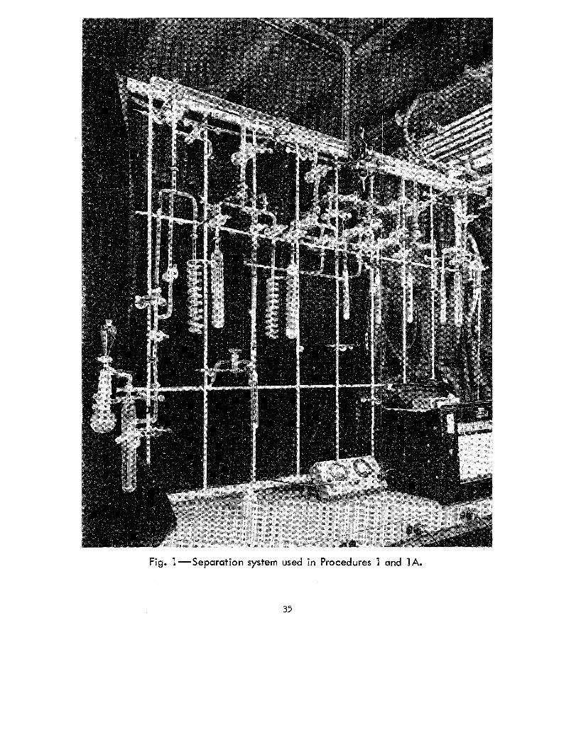
Fig. 1-Separation system used in Procedures l and 1A.
35
PROCEDURE 1 (Continued)
er traps. each containing 10 grams of activated charcoal; 5) T 2 , an unpacked
trap similar to the preceding three; 6) a 200-cc bulb; 7) an outlet for sample
removal; and 8) a mercury manometer. Helium is admitted to the line
through the charcoal trap at the lower left. This trap is cooled in liquid nitro
gen to remove trace impurities from the helium. Partially obscured by this
charcoal trap is another manometer between T 1
and C 1
which may be closed
off from the system with a stopcock. It is certainly not obvious from the
photograph but connections and stopcocks have been so arranged that helium
flow may be directed through any charcoal trap, through an ionization chamber
(unseen behind the drape), into any subsequent charcoal trap, and thence to
the atmosphere. The current through the ionization chamber is ampll.fied by
a vibrating reed electrometer whose output drives the recorder partially seen
at the right of the bench. Thus a continuous record of activity in the ionization
chamber during a separation is obtained. To the left of the recorder is the
thermocouple vacuum gauge power supply and meter. The large traps are
constructed of 41-mm and the small traps of 22-mm o. d. glass tubing, and
their respective lengths are about 25 and 20 cm. The charcoal is Columbia
Grade-G activated charcoal (6-14 mesh), ground in a ball mill and sieved to
yield 20-50 mesh material.
The system is used for the separation of rare gases from various types
of samples, and the procedure described below admittedly does not treat a
problem often encountered. It was chosen to represent the extremes of
sample size, flow rates and partial pressures of rare gases for which separa
tion has been successfuily achieved with the system, arid to afford a frame
work within which the largest number of operations could be described.
The sample is 100 cubic feet (STP) of air compressed into a bottle con
taining 100 cc STP of active krypton and 75 cc STP of active xenon. Average
yields are about 90% for krypton and 95% for xenon. The time required for
the separation is about 8 hours of which 3 hours are spent in bleeding the
sample into the system. Before the run ail charcoal traps have been heated
to 350 °C and pumped on until .the thermocouple vacuum gauge in the manifold
is "pinned" (probably less than 10- 4 mm Hg).
1. Gallon dewars of liquid nitrogen are placed on T 1
and C 1
, including
the glass coils. The refrigerant level should be above the connection from
coil to trap.
2. Through a pressure gauge and reducing valve the sample is connect
ed to the line below the flowmeter. Sample is bled into T 1
and C 1
until equi'
librium pressure oyer C 1 is about 35 cm Hg. Wait a few minutes until ther-
PROCEDURE l (Continued)
mal equilibrium is reached as evidenced by steady_ pressure and decreased
boiling of the liquid nitrogen.
3. Using a mechanical pump on the exit from c1
and suitable valving,
establish sample flow through T 1
and C 1
of 15 liters S_TP per minute at about
35 cm Hg pressure. Reduced pressure is necessary to avoid condensatio_n of
liquid air in the system. An NRC-45 Rotary Gas Ballast Pump* (4 cfm) is
used to handle the necessary large amounts of air over prolonged periods.
Keeping the liquid nitrogen replenished, bleed the sample in at the above rate
until the pressure in the bottle is about one atmosphere. Pumping for a few
minutes with all valves open completely will reduce the pressure in the bottle
to about 10 cm Hg. This represents sufficiently quantitative removal of the
rare gases from the bottle.
4. Close the manometer by C 1 and the stopcock at the exit side of T 1
,
place liquid nitrogen on c 2 , c3
and c4
, and introduce helium at 1-2 psi gauge
to all the charcoal traps. Thermal and pres sure equilibrium in the traps will
be evidenced by cessation of helium flow into the system.
5. Set up helium flow of 1250 cc STP per minute through C 1
, the ion
ization chamber, c 2 in liquid nitrogen, and thence to the air. When steady
flow is established remove the liquid nitrogen from C 1
. Allow C 1 to warm
slowly in air for 5-10 minutes. (This avoids high pressures in the system
from too rapid desorption of the roughly 30 liters STP of air adsorbed on C 1
).
After 10 minutes immerse c1
in 10-20°C water. Krypton activity will be ob
served in the ionization chamber in about 5 minutes, the activity rising rapidly
to a miximum and then dropping off more slowly (full-width at half-maximum
about 2 minutes). When the activity is less than 1% of the peak value (10-15
minutes), the elution is halted.
6. Set up helium flow of 750 cc STP per minute through c2
in liquid
nitrogen, into the ionization chamber, and thence to the air. Remove the
liquid nitrogen from c 2 and after a couple of minutes immerse c2
in dry ice
acetone slush (-78. 5°C). Elute approximately ten minutes to remove air
from c 2 . If activity appears in the ionization chamber before this period is
up, stop the elution immediately and proceed with the next step.
7. Direct the helium flow (750 cc/min) so that the sequence is C2
in
* National Research Corporation,Equipment Division, Newton Highlands
61, Mas sachus et ts.
37
PROCEDURE l (Continued)
dry ice-acetone, the ionization chamber, c3
in liquid nitrogen, and out to the
air. Remove the dry ice-acetone from C 2 and replace with l 0 -'ZO °C water.
The krypton activity will appear in 1-Z minutes in the ionization chamber.
Full-width at half-maximum is about 30 seconds. Elute until activity in the
ionization chamber is less than 1% of the peak value (should take less than ten
minutes), and stop the elution at that point.
8. Repeat Step 7 to elute krypton from c 3 to c 4 .
9. With c 4 s·till in liquid nitrogen, pump until the pressure on the ther
mocouple vacuum gauge in the manifold is less than one micron. This should
require less than five minutes and results in the removal of helium from c4
with no loss of krypton. If the trap does not pump down to one micron in less
than five_ minutes, discontinue pumping and proceed to the next step.
10. Place Tz in liquid nitrogen. At this point c4
contains the krypton
and some residual air. The removal of air is essentially accomplished by
warming c 4 slowly, passing the evolved gases through T 2 in liquid nitrogen
to condense any krypton evolved, and every time the pressure reaches about
l/Z atmosphere in the system beyond T z pumping the gas off briefly by rotat
ing the stopcock to the vacuum manifold through the open position. It should
be borne in mind that once krypton is condensed in T z the partial pressure of
krypton in the system beyond is Z-3 mm Hg (the vapor pressure of krypton at
liquid nitrogen temperature) and that one thus wishes to keep the total time
which one pumps on T z to a minimum to reduce losses. Remove the liquid
nitrogen from C 4
and allow the trap to warm in air a few minutes until evolu
tion of gas begins, use the pump in the manner described above, and each
time evolution of gas slows down speed the process by heating the trap to
successively higher temperatures (dry ice-acetone, room temperature water,
and finally warm water -- about 40 °C). When the trap is at 40°C and the
pressure in the system is steady, pump off the last vestiges of air, leaving
Z-3 mm Hg pressure of krypton in the system. (The distillation of krypton
from c 4 to T Z will be seriously slowed by any observable pressure of residual
air). Allow 5-10 minutes for the complete distillation of krypton. If the vol
ume of the system has been measured beforehand, the stopcock between C 4
and T2
may be closed, T2
warmed to room temperature, and the pressure of
krypton measured to get a rough determination of the yield. Yield should be
about 90%. Distill the krypton into an evacuated bulb attached to the system
outlet and cooled in liquid nitrogen, and remove from the line.
11. Place boiling water on Cz and c 4 and pump down to base pressure
38
PROCEDURE 1 (Continued)
to remove traces of krypton. Cool the traps to room temperature, then place
in liquid nitrogen, and admit helium to speed the cooling.
12. Set up helium flow of 1250 cc STP per minute through C 1 at room
temperature, the ionization chamber, c 2 in liquid nitrogen and thence to the
air. The xenon will be eluted to c 2 from C 1 in boiling water in about an hour.
The time may be reduced to about 3 0 min. by heating C 1 more rapidly in a
furnace set to reach an eventual temperature of 350"C. Elute to less than 1%
of peak activity.
13. Set up helium flow of 750 cc STP per minute through c 2 in liquid
nitrogen, the ionization chamber,. C 4 in liquid nitrogen, and thence to air.
Warm c 2 to about 4o•c and throw away any small krypton peak which appears
(less than five minutes). Elute xenon to C 4
using either boiling water or a
furnace as in Step 12 (15 to 30 min.).
14, Tz is cooled in liquid nitrogen, c 4 warmed to lOO"C, residual air
pumped off if any is present, and the xenon distilled to T 2 in 10-15 minutes.
Xenon losses are slight in this process as the vapor pressure a.,!" liquid nitro
gen temperature is only about 50 microns. Measure the xenon yield (should
be 95% or greater) and distill to an evacuated bulb for removal from the line.
Comments
l. For smaller samples in which the rare gas partial pressures are
higher over T 1 the possibility that a large fraction of the xenon may originally
be condensed in T 1 at -195 •c should be noted. (It seldom happens that this
occurs with krypton since its vapor pressure is higher (Z-3 mm Hg) at -19s•c,
but partial pressure of krypton over the trap should also be considered with
each sample). If this occurs and one wishes quantitative recovery of the xenon
one could distill xenon to C 1 before starting the elutfon from C 1 . It is usually
more convenient to recover the xenon from T 1 and C 1 separately however.
The fastest way to accomplish the recovery from T 1
is as follows: Cool the
glasa coil before T 1 in liquid nitrogen. Use an induction coil to produce eddy
currents in the steel balls and thus heat them rapidly to well above room tem
perature. Pump off residual air which may have been occluded in the conden
sate through the glass coil and then distill the xenon, carbon dioxide, and
water into the coil. Distill xenon and carbon dioxide from the coil at -78. 5•c
into a bulb attached to the outlet at the upper left of the rack and cooled in
liquid nitrogen. Thaw and. refreeze the water several times until occluded or
dissolved gases are removed. On another rack remove the C02 from the
xenon by pas sage through As carite or by distilling the xenon from a bath. at
39
PROCEDURE 1 (Contm.ued)
about -lso•c into hqilid nitrogen. The vapor pre111i.1re of xenon at i11opentane
'"•luah'' temperature (-160.C) i• only a few- nun Hg 10 liq.iid i11opentaJJ.e at a
few •c higher temperat.ire i• usually 1111ed to 11peed the di•tillauon. One may
of co11r11e u11e dry ice-acetone on T 1
to remove water without condenaing Kr
and Xe. Moat of the carbon dioxide will then pa1111 onto c1
.
Z. Cro1111-contamm.anon of the krypton and xenon fracnon• ha11 never
been ob11er"1.""ed in term11 of their radioactivity. In one run WJ.th inactive krypton
and active xenon, the krypton wa11 di11nlled directly off of Cz after the elution
from C 1 and no xenon activity wa.11 observed m. the kr}'Pton. A lower limit for
the aepa.ration factor in thi11 one el.inon of 5 x 10³ wa11 calculated. It thua
appeara quite likely that the two 1ub11equent elution& could be eliminated m.
many experiments.
3. The inclusion of a thermal conductivity cell in aer1e11 with the 1om.za
tion chamber to allow detection of nonradioactive 11pecie11 el.ited from the char -
coal haa proved to be a "-aluable il.ld in many operauon11. As an example, the
elution of air from the charcoal trap11 conta1111ng Kr can be performed more
efficiently ii one can observe the emergence of the il.lr ·'peak•· .. Aleo, with
rare ga11 1ample11 not active enough to register in the ionization chamber, one
can observe the elution peak11 of the carriers in the thermal conductivity cell
rather than operanng purely on the baai11 of previously observed retention
nmea.
4. In a recent modification which promiaea to improve the versatility
of the 11y11tem1 the. second a mall charcoal trap, c 3 , wa11 replaced with 60 gram11
of 30-~0 me11h SA Linde Molecular Sieve in a coiled gla!lll col.unn. about l cm
in diameter and lZO cm l~. Separations of methane-krypton mixturea (typ
ically about SO cc STP of each) have been performed very 11ati1factorily on
th111 colw:nn. Eluting the mixture from Cz to the top of thla coliJ.mD at -19s•c,
and then raising the temperature to -36 •c (ethylene dichloride ·'11lu11h"}, the
following eluuon da.~ with He flow of 600 cc STP pe_r minute were foilDd in
11e"-eral ri.l.D.S: Kr, peak retention time 18 nun. , full-width at half-ma.ximillll
3 min.; CH4
, peak retention time 3S min., foll-width at half-maximllln 8 min.
PROCEDURE lA - REMOVAL AND SEPARATION OF Kr AND Xe
FISSION PRODUCTS FROM Uz 3s TARGETS
Thie proced.ire ill uaed for Uz3 s target• of the order of 100 mg m. weigh~ and clad in a few hundred :milllgram• of ZS aluminw:n.
Even though only one of the rare ga11e1 ill of intere•t it ia the practice to
PROCEDURE lA (Continued)
add carriers for both to circumvent the vagaries of tracer behavior. The
amount of carrier added is determined by the usual considerations concerning
the counting operations to be performed later, but 100 cc STP each of krypton
and. xenon would be typical.
The system as shown in Figure l may be used for the separation. Safety
precautions such as shielding and containers to catch active solutions in case
of breakage must of course be provided. The dissolver flask at the extreme
left is a 250-ml round bottom flask fitted with a 34/45 inner-tapered ground
glass joint, fitting an outer 34/45 joint into the top of which a separatory
funnel has been sealed. The outlet for evolved gases is through an arm at
the top fitted with an 18/9 ground-glass ball joint. The trap to the right of
the flask is packed with Ascarite.
l. A bulb containing the carriers is attached at the upper left of the
rack. The target is placed in the flask and the tapered joints greased and
fitted together. Air is evacuated from the entire dissolver system. This is
permissible with most targets as the diffusion of the rare gases from uranium
at roo;m temperature is negligible. The other alternative is to pull the air in
the system onto C 1
at -195 °C. T 1 is cooled in dry ice-acetone and C 1 in
liquid nitrogen.
2. With the stopcock before C 1 closed, open the carrier bulb to allow
carriers to expand through the rest of the system. Start the solution by dr.ip
ping in concentrated HCl with a few drops of 30% H 2o 2 added. Rate of reac
tion may be controlled by warming or cooling the flask. A wet towel contain
ing ice may be wrapped around the neck of the flask to reflux most of the ·water
and acid fumes back into the solution. Inclusion of a reflux condenser cooled
with ice water above the dissolver is more esthetically pleasing and probably
more efficient. If hydrogen pressure approaches atmospheric it may be nec
essary to transfer some to C 1
during the solution. (See Note 4 below). Dilute
the final few cc of solution to 20-30 cc with cold water and cool in an ice bath.
3. Close the carrier bu.lb to retain some carrier for flushing. P~ll
other ga11es onto C 1 to a residual few mm Hg of hydrogen. The .solution should
boil -- warm slightly if necessary. It was originally cooled to avoid too vig
orous boiling and eplashing during this operation.
4. Close the stopcock to C 1 and open the carrier bulb. Again pull all
gases onto C 1 .
5. Close the stopcock to C 1
and admit a few cm Hg of air to the system
through the separatory funnel. Pull the air onto C 1. (Provisions for the use
of helium for this final flu.sh of the system would be desirable).
41
PROCEDURE IA (Continued)
6. Krypton, xenon, hydrogen and air are now on C 1
at liquid nitrogen
temperature, and one follows the pr.evious procedure starting from Step 4.
The final steps will. be simpler as the sample contains very little air, and the
hydrogen is nearly quantitatively removed by the elution from dry ice-acetone.
7. Radiochemical analyses necessary for the purpose of the experiment
are performed on the target solution. As an example, in caHbrating Kr88
counters one might assay Mo 99 to determine the number of fissions in the
target, assuming calibration factors for this fission product to have been pre
·vioasly determined.
Notes
1. The system has given results in calibration runs which are indistin
guishable (the same to within 2-3%) from those obtained with an earlier sys
tem in which a portion of the carriers was admitted to the system prior to
.solution, the rest bubbled through the clear solution, and the entire system
finally flushed out through C 1 with heliwrt bubbled in through the solution.
2. In the absence of air the system has been used to separate argon,
krypton and xenon. The argon is adsorbed along with the krypton and xenon at
liquid nitrogen temperature, and eluted off the charcoal at - 7 8. 5 °C .. The a:t -
gon will not be s.eparated from nitrogen and oxygen if air is present~ and in
this case chemical means are used to purify the argon.
3 In . . l . x 135 . . h' f h f . experiments invo v.i.ng e separations wit in a ew ours o
. . di . "d . f r135 h" h h l ha b b d irra ation, no ev1 ence o reac ing t e c arcoa s ever een o serve .
Results of the experiments performed were generally not very sensitive to
r135 contamination, however. In e)cperiments where results would be greatly
affected by slight iodine contamination of the xenon fraction, this point should
be checked more closely. Detaile.d Procedures 4 and 5 contain examples of
other effective means of iodine removal.
4 ... In building a system for the solution of various types and sizes of
targets, the author would recommend inclusion ahead of T 1 of a trap packed·
with CuO and heated to 500°C for conversion of hydrogen to wat.er, followed
by a trap filled with a desiccant, such as magnesium perchlorate. The size
target which may be dissolved in a system of convenient volume is then not
limited by the volume of hydrogen evolved, and the fact that the system contains
only the rare gases and a small amount of unburned hydrogen after dissolution
is comple.te simplifies the total interchange of carrier and activity as well as
the ultimate quantitative transfer of the carriers to c1
. Such a system.has
been used successfully for the dissolution of targets weighing up to a few grams.
PROCEDURE Z -THE EXTRACTION, PURIFICATION
AND INDUSTRIAL USES OF Kr85
Source - E. J. Wilson, C. Evans, J. Chadwick, J. Eakins,
K. J. Taylor, report AERE I/R ZZ16 (1957).
The procedure described in this paper is for the recovery of fission
product krypton from kilogram amounts of irradi.ated uranium· metal. A brief
description of the operations involved is given below to point out methods which
may be applicable to smaller scale experiments.
1. Three Z. 3-kilogram uranium slugs containing fission product krypton
are dissolved in a 70-liter stainless steel ·container. Dissolution is accom
plished with roughly lZ liters of 10~ HN03
at 104°C. The dissolution is car
ried out "fumelessly" with respect to oxides of nitrogen by admitting oxygen
over the solution (See Note 1). Approximately 6 liters of water are used to
recombine acid fumes and wash them back into the vessel during solution,
Solution is complete iri about ZO hours and the final result is a solution of uranyl
nitrate in approximately 3~ HN03
. A slight excess of oxygen is used to main
tain flow to the purification train during dissolution and the di1i1Bolver system
is finally flushed with helium to effect complete removal of fission gases to
the purification train.
Z. Gases leaving the dissolver are circulated around an apparatus in
which they receive the following treatment: 1) rough drying with CaC12 , 2)
carbon dioxide removed with Sofnolite (an NaOH-CaO mixture), 3) final dry
ing with magnesium perchlorate, 4) removal of oxygen by reaction with cop
per turnings at 600°C, 5) any water from oxidation of hydrogen or hydrocar
bons removed with Sofnolite, 6) traces of hydrocarbons and gaseous compounds
of nitrogen removed by reaction with. clean uranium turnings at about 800 °C,
and 7) rare gases adsorbed on charcoal at liquid nitrogen temperature. From
the charcoal trap, remaining gases (mainly heliwn) return to the point of entry
from the dissolver. The system is initially fil.la:lwith one atm_osphere of
helium. A loosely inflated balloon attached to the system maintains the pres
sure at one atmosphere during ·sudden bursts of evolved, gases. Circulation of
about one liter per hour is maintained by two identical parallel pumps consist
ing of a chamber permitting unidirectional flow within which the pressure is
varied by periodic heating and cooling.
3. Upon completion of the dissolving and flushing the dissolver with
heliw:n the charcoal trap will contain all the fission product krypton and xenon.
Argon present as an impurity in the oxygen used for dissolving will also be
adsorbed on the charcoal and will in fact constitute the bulk of the adsorbed
43
PROCEDURE 2 (Continued)
gases (several hundred cc STP). The charcoal trap is removed from the line
and the rare gases desorbed by warming the charcoal in boiling water and
evacuating with a Toepler pump. The desorbed gases may be transferred di
rectly to the final purification apparatus with the Toepler pump, or if the total
volume of the rare gas fraction is very large, it may be most convenient to
transfer the gases first to a series of storage bulbs. The smaller aliquots of
rare gases contained in these bulbs may then be. purified singly as convenient.
4. The final purification apparatus consists of a train of five charcoal
traps. All are heated and outgassed to a vacuum before the run and then all
but the second are cooled in liquid nitrogen. The second trap is the chromato
graphic column. It contains 10 grams of charcoal in a column about 20 cm
long and is cooled to -50°C with a dry ice-chlorobenzene mixture. The sample
of rare gases to be separated is transferred to the first charcoal trap cooled
in liquid nitrogen. Helium is introduced to saturate all charcoals at atmos -
pheric pressure and a flow of 3. 5 liters per hour of helium set up through the
train of charcoal traps. Gradual lowering of the dewar around the first trap
transfers first the bulk of the argon to the chromatographic column, and
finally upon complete removal of the dewar the remaining gases deposit in
diffuse bands at the head of the column.
5. Radioactivity in th~ gas leaving the column is monitored with a GM
counter suitably placed near the exit line from the charcoal. Until activity is
n.oted in the effluent gas the flow is directed from the column to the last char -
coal trap (a precaution in case of an error in judgment). As s·oon as activity
is noted the flow is changed to pass through all three charcoal traps subs~quent
to the column. Activity appears in about an. hour and approaches background
in 2-3 more hours. The elution is stopped at this point with most of the kryp
ton removed from the column and all the xenon still adsorbed. Helium is
pumped off the charcoal traps while still cooled in liquid nitrogen.
6. The krypton may.at this point contain a few volume percent of hydro
carbons previously undecomposed by uranium and unseparated from krypton
by cltarcoal chromatography. These are removed by warming the krypton
containing charcoals in boiling water and circulating the evolved gases over
uranium turnings at 800 •c to decompose hydrocarbons, and then over pyro
phoric uranium at room temperatl!-re to remove any hydrogen resulting. Puri
fication is considered complete when the pressure in the system reaches a
steady state.
7. Krypton is transferred to suitable storage bulbs with a Toepler pump,
44
PROCEDURE 2 (Continued)
or by adsorption on charcoal contained in the storage bulbs and cooled to liquid
nitrogen temper.ature.
Notes
l. The dissolution of uranium in nitric acid has been studied in detait.85
The dissolution in 11. 7M HN03
proceeds according to the following equation:
u +4.5 HN03 - UOzCN03lz + 1.57 NO +0.84 NOz +0.0005 NzO +0.043 Nz +2.25 HzO.
In the presence of oxygen, however, the equation for the reaction is U + 2 HN03
+
3/2 o 2 - uo2 (N03
)2 + H 20, so that oxides of nitrogen are not present in the
products.
2. Xenon could of course be recovered from the chromatographic column
at 100°C if desired. Jn this particular procedure the uranium is dissolved
after xenon activities have largely decayed to avoid working with high levels of
radioactivity. There is a report describing the early recovery of multi-curie
amounts of Xe 133
from uranium. 86
Aside from problems of shielding and
remote control introduced by the high levels of radioactivity, the procedure is
very similar. The same dissolving and preliminary purification apparatus is
in fact used. As xenon is s.o much more strongly adsorbed than argon, the
argon is removed by pumping on the charcoal containing the rare gases with
the trap at -90°C, rather than by elution from a charcoal column. The final
xenon fraction contains some argon and most of the fission product krypton
- present in the sample. As the final step in the procedure (after all the steps
in the Kr 85
purification) trace impurities other than rare gases are removed
. h l . 7 Th f . wit a ca c1um getter. e apparatus or this step consists essentially of a
stainless steel crucible containing calcium chips and heated to 550-600°C. A
"mirror" of calcium is deposited on an adjacent cold pyrex glass surface.
Cleanup is followed by taking periodic pressure measurements with a McLeod
gauge and is considered complete when no further pressure decrease occurs.
To obtain smaller amounts of Xe 133
(of the order of 50 millicuries ),
solution of 10-ZO gram amounts of irradiated uranium was carried out with
nitric acid and oxygen in a smaller system. -Effluent gases were passed
through a trap packed with glass rings and cooled to -80°C to remove water
vapor and N02 . Complete removal of xenon was again effected by sweeping
the solution with h.elium, and the helium stream was passed through a charcoal
trap at -5o•c to ~dsorb tfe xenon. Subsequent purification of the xenon follow
ed the same pattern except that 0. 03 cc STP of inactive xenon carrier was
added.
PROCEDURE 3 - RAPID REMOVAL OF FISSION
PRODUCT Kr FROM U FOIL
Source - G. D. O'Kelley, N. H. Lazar, and E. Eichler,
Phys. Rev. lOZ, ZZ3-ZZ7 (1956)
This procedure was used to obtain samples of the 15-min. Rb8
9 for
study and the operations are briefly described below as given for this purpose.
The technique for removal of krypton from the target may prove useful in other
contexts.
The target is a uranium film (0. 3 mg/cm2
) deposited on. a 1. 6-cm-diam
eter Pt disk. It is mounted at one end of a vacuum-tight recoil chamber with
a 3. lZ mg/cm2 Al foil between the uranium and the ~ecoil chamber. This
amount of aluminum absorber should stop Xe fission fragments but permit
passage of the krypton fission fragments into the recoil chamber. A rubber
serum bottle cap is used to cover and seal the exit line at the opposite end of
the recoil chamber from the target.
1 · Target and recoil chamber are placed in a pile and irradiated with
neutrons for 3 minutes, (The half-life of Kr 89 is Z. 6 min.)
Z. The target is removed rapidly from the pile via a pneumatic tube
and krypton isotopes shorter-lived than Kr 89 allowed to decay out for 3 min.
3. The rubber cap s·ealing the recoil chamber is punctured with a
double-walled hypodermic needle. Air is flushed down the center tube of the
hypo, and air containing the krypton in the recoil chamber exits through the
coaxial outer annulus of the needle. The effluent gases are passed through a
trap packed with glass wool and cooled in dry ice-acetone and thence into an
evacuated cell. The Rb89 daughter of Kr 89 is collected on a negatively
charged strip of Al foil for 3 min. The foil is removed and Rb 89 counted.
Due to straggling some xenon recoils penetrate to the recoil chamber, and a
·few percent by activity of Cs 138
is found on the foil.
PROCEDURE 4 - RECOVERY OF FISSION PRODUCT
Xe FROM U MET AL
Source - E. J. Hoagland and N. Sugarman, Paper 147:
Radiochemical Studies: The Fission Products,
National Nuclear·Energy Series, Div. IV, Vol. 9,
Book 2, McGraw-Hill, New York ( 1J5 l) pp. 1035.
This procedure effects rapid dissolution of the target and separation of
iodine and xenon fission products. It was designed for studies of the indepen
dent fission yield of Xe 135
46
PROCEDURE 4 (Continued)
1. The uranium target is placed in the dissolver flask, and the flask
attached to the vacuum line in which the separation is to be performed. Air
is evacuated from the entire apparatus and helium is then admitted to about
one half atmosphere pressure.
Z. The target is dissolved in concentrated HCl containing a small
amount of I for "holdback" .carrier. After the metal is dissolved any resid
ual oxide or carbide may be dissolved by the addition of a small amount of
cone. HN03
. It was found that iodide ion was not oxidized during dis solution
if present originally in low concentration.
3. The liberated gases are passed in succeesion through .a cold trap at
-85°C, a cone. NaOH solution, an NaHS03
solution, two cold traps at -85°C,
an activated charcoal trap at -85°C, and an activated charcoal trap at -195°C.
When dissolution is complete the solution is swept with about 300 cc of helium
at 10 cm Hg over a period of 3-4 min. (See Note 1, below). The procedure
to this point can be completed.within 10 min. after the end of an irradiation.
The dissolver flask is i:mznediately closed off.
4. All the xenon and some of the krypton are now on the charcoal trap
at -85 °C. The remainder of the krypton is on the second charcoal trap at
- 195 °C. In this procedure the first charcoal trap is heated to Z50 •c and the
desorbed gases (containing all the xenon) transferred by a Toepler pump to an
evacuated storage bulb. Aliquots of xenon for counting are taken by filling
thin-window gas-tight containers from the storage bulb.
5. The amount of Xe 135
growing into the target solution from 1135 may
be determined by repeating the helium sweeping at a suitable known later time
after irradiation and counting an aliquot of the xenon fraction so obtained.
Early experiments indicated n~ 1135
reached the first cold trap, NaOH solu
tion, or NaHS03 solution. Thus the helium sweep containing the xenon activ
ity may be transferred directly to the storage bulb, and aliquots for counting
taken.
Note
1. The double-ended dissolver flask used in this procedure is illustrat
ed in the article. The closed end is used for solution of the target and storage.
For sweeping with helium the flask may be rotated through 180° about the
horizontal axis of the sidearm c.onnecting it to the system through a tapered
glass joint. The solution then rests on a sintered glass disk through which
helium m.ay be introduced. A small bulb between two stopcocks below the
47
PROCEDURE 4 (Continued)
sintered glass disk is used to measure out aliquots of helium for sweeping.
Efficiency of xenon removal by the helium sweep was found to be about 95"/o.
PROCEDURE 5 - RAPID REMOVAL OF FISSION PRODUCT
Xe FROM U03 OR UOz(N03)z . 6Hz0 TARGETS
Source - F. Brown and L. Yaffe, Can. J. Chern. ~· 242 (1953).
This procedure was also designed for studies of the independent yield 135 6 . of Xe . The targets used were 200-300 mg of uo
3 or U0
2(N0
3)2 · H 20
enclosed in thin-walled aluminum capsules.
The target is placed in a flask containing about 50 mg of KI as holdback
carrier, attached to the vacuum system, and the apparatus evacuated. H2
is
started bubbling through the solution and hot 1:1 sulfuric acid admitted to /
dissolve the capsule and contents rapidly. The solution is boiled while hydro-
gen is bubbled through. Effluent gases pass through a reflux water condenser
for rough drying, a trap cooled to dry-ice temperature, a trap containing
NaOH pellets, and two charcoal traps at dry-ice temperature in succession.
H2
bubbling is continued until 30 min. after the end of irradiation. Charcoal
traps are evacuated to less than 5-microns pressure and sealed off with cool
ant still in place. Kr and Xe activities are on the first trap, and Kr but no
Xe activity on the second. The xenon activity is counted by placing the char
coal trap in a well-type ionization chamber. Later samples of xenon may be
obtained for determination of the xenon activity growing into the solution by
repeating the hydrogen sweep.
PROCEDURE 6 - SEPARATION OF LONG-LIVED FISSION GASES
Source - J. A. Ayres and I. B. Johns, Paper 311:
Radiochemical Studies: The Fission Products,
National Nuclear Energy Series, Div. IV, Vol. 9,
Book 3, McGraw-Hill, New York (1951), pp. 1763.
This procedure was used in studies of the efficiencies of various methods
of xenon removal from uranium metal, and gave results reproducible to Z-3o/o.
The uranium sample containing fie sion product xenon is placed in a dis -
tilling flask, and the flask connected to the purification train. Air is removed
by flushing the entire apparatus with co2
. The uranium is then dissolved by
running in 92"/o H3P04 , the rate of reaction being controlled by warming or
48
PROCEDURE 6 (Continued)
cooling the flask as required. Dissolution is very fast at the boiling point of
the acid. Xenon, hydrogen, and some fission product iodine and tellurium
enter the purification train. Bubbling the gases through a saturated NaHS03
solution removes I and Te. Passage over hot CuO oxidizes the H 2 to H 20,
which is condensed in a subsequent flask. The active xenon and small amounts
of other gases· are then collected in a eudiometer over KOH~ After the uran
ium is dissolved, any xenon remaining behind is swept from the solution into
the eudiometer with C02
. After the C02 is removed by reaction with KOH,
air may be swept in ir'necessary to provide an easily handled volume of gas.
The sample is withdraWll to an evacuated bulb connected to a counting chamber
into which an Al finger-type GM counter is sealed. · Tlie aliquot of the xenon
being counted may be calculated from knowledge of the volume of the counting
chamber and of the rest of the system containing the sample.
PROCEDURE 7 -REMOVAL OF Rn FROM Th TARG~TS AND ITS
COLLECTION ON THE CATHODE OF A DISCHARGE TUBE
Source -·F. F. Momyer and E. K. Hyde,·
Journal of Inorganic and Nuclear Chemistry,
L 274-95 (1955).
The overall yield of this procedure is no more than a few percent. It
has proved useful, however, for the collection and retention _of rare gases. on
wires or foils in ~tudies of de.cay characteristics. of rare gas nuclides ~
The thorium metal target, irradiated with 340-Mev protons to produce·.
radon i.s.otopes by spallation, is placed in the dissolver flask, the system
evacuated, and hot concentrated HCl containing ammonium fluosilicate catalyst
dropped in to dissolve the thorium. Evolved gases are bubbled. thrpugh sodium
hydroxi.de solution, passed through a trap cooled in dry ice/a~etone, and then
passed through 3 successive traps cooled. in liquid,nit.rogen .. After solution
is complete .the dissolver and sodium hydroxide solution are clos.ed off and the . . -4 -5 .
4 cold traps pumped down to .10 . - 10 mm Hg. The tr!lpS are shut of.I from
the pump and gases condensed in the traps are distilled to the last trap ~y
keeping it immersed in liquid nitrogen and warming the others. The contents
of this trap are finally distilled into a tip on the glow discharge tube which is
cooled in liquid nitrogen. The discharge tube is then closed off, the tip
warmed, and a glow discharge run for a few minutes to collect radon on the
cathode. This technique has been discussed earlier in this monograph under
counting procedures. Usually, small amounts of condensed impurities pro-
49
PROCEDURE 7 (Continued)
vide a few hundred microns pressure to support the dischar.ge. If this is not
the case, one may add some gas such as air, nitrogen or helium to achieve
the necessary pressure in the discharge tube. Any radon not deposited on the
cathode may be frozen back into the last trap at liquid nitrogen temperature
for use in later experiments.
Notes
1. Stoner and Hyde 76 studied isotopes of radon produced by bombard
ment of gold with nitrogen ions in similar fashion. The gold was dissolved in
mercury while being heated by induction to remove the radon from the target.
Z, Matqur and Hyde 77 studied neutron deficient x~non isotopes produced
by bombardment of KI with 100-Mev protons using a similar procedure. The
KI was dissolved with water in a closed system and the xenon removed from
solution by pumping through the same series of traps used in the radon pro
cedure. "The NaOH scrubbing was omitted.
3. The observed retention of trace amounts of rare gases in traps at
-195 °C should be coIIlil'l.ented upon. It was also observed in the radon experi
ments that fission product rare gases and their interfering ~-y activity could
be largely removed from radon by warming the trap containing all the gases
briefly in air and distilling the fission products into another trap at -195 °C.
Distillation was monitored with a (3-y survey meter and continued until the
activity in the trap ceased to drop rapidly (about 30 sec). Well over 90% of
the rare gas fission product activity in the. radon could be removed thus. The
vapor pressures of the rare gases at -195°C certainly exceed the partial pres
sures of the tracer amounts of rare gases in the above experiments. Retention
in the cold traps is thus not due to condensation of the pure solids. Speculation
as to the exact mechanism involved seems pointless without further experimen
tal data. It seems worth calling attention to the fact that the retention is not
a result of processes involVing the rare gases alone (that is, adsorption on or
condensation with other substances must be involved), so that circumstances
under which trace xenon, for example, might not be held up in a portion of a
system at -195°C are possible.
PROCEDURE 8 - DETERMINATION OF ACTIVE GAS HALF-LIVES
BY THE CHARGED WIRE TECHNIQUE (II)
Source:.._ C. R. Dillard, R. M. Adams, H. Finston, and A. Turkevich,
Paper 68: Radiochemical Studies: The Fission Products~ National Nuclear Energy Series, Div. IV, Vol. 9, Book 2,
McGraw-Hill, New York (1951), pp. 624.
A number of the earlier experiments to determine the half-lives of
short-lived rare gases were performed using this interesting technique.
A solution of uranyl nitrate is contained in a small polystyrene vessel
over a porous graphite disk through which nitrogen may be bubbled. The
vessel is connected through a baffle system, to prevent spray carry-over, to
a 10-ft aluminum tube of 1-in. inner diameter. A fine copper wire do.wn the
center of the tube is maintained at -1000 volts to effect collection of the daugh
ters of gaseous activities passing through the tube. The entire apparatus is
placed in a reactor and the solution irradiated with neutrons while maintaining
a constant flow of nitrogen through the system. From experimental data the
linear flow rate of gas thro~gh the aluminum tube may be calculated. Thus by
cutting the collector wire into a number of equal lengths and determining the
relative amounts of daughter activity on each piece, the half-life of a short
lived rare gas with a daughter of appreciable half-life may be determined with
fair accuracy.
51
REFERENCES
l H. Remy, Treatise on Inorganic Chemistry, Vol. l, (translated by J. S.
2 Anderson), Elsevier Publishing Co., New York, (1956~.
M. Steinberg and B. Manowitz, Ind. Eng. Chem., 51, 47-50 (1959). 3 . . -
H. M. Powell, J. Chem. Soc. London, p. 298, 300, 468 (1950). 4 . . . H. M. Powell, J. Chem, Soc. London, Part 2, 2658 (1954).
5 . . D. J. ChleckandC, A. Ziegler, Nucleonics.!2_, No. 9,130 (1959).
6 . S. Katcoff and W. Rubinson, Phys. Rev. 91, 1458-69 (1953).
1 -F. Soddy, Proc. Roy. Soc. A78, 429 (1906).
8 A. S. Newton, AEC report series .M. D .. D. C. 724 .. 9 . . . . W. D. Bond and W. E·. Clark, "Reduction. of CuO by Hydrogen. II.
10
11
Conversion of Hydrogen to Water over Fixed Beds." Oak Ridge National
Laboratory report ORNL-2816 (1960).
F. R. Bruce, J. M. Fletcher, H. H. Hyman, and J. J. Katz, editors,
Process Chemistry, Progress in .Nuclear Energy, Series ID, McGraw
Hill, New York, or Pergamon Press, London, (1956), p. 345.
F. Brown and L. Yaffe, Can. J. Chem. 31, 242-9 (1953). 12
O. E. Myers and R. J. Prestwood,. in R~oactivity Applied to Chemistry,
A. C. Wahl and N. Bonner, Editors, John Wiley and Sons, Inc. New York,
( 1951), pp. 28-29. 13 E. J. Wilson, Vacuum 3, 287-88 (1953). 14 N. S. Corney, et aL, AERE-C/M-364, Feb. 1959. 15 .
A. Sayres and C. S. Wu, Rev. Sci. Instr. 28, 758-64 (1957). 16 N. V. Sidgwick,, The Chemical Elements a~ Their Compounds, Vol. I,
Oxford, Clarendon Press (1950), p. 1. 17 F. J. Allen and P. B. Moore, JACS 53, 2512-22 (1931). 18 .
F. J. Metzger, Ind. Eng. Chem. 27, 112-16 (1935). 19 M. Ruhemann, Separation of Gaile~ 2nd Edition, Oxford, Clarendon
Press (1949). 20
G. H. Cady and H. P. Cady, Ind. Eng. Chem., Anal. Ed. !2.i 760-6 (1945).
21 E. Glueckauf and G. P. Kitt, Proc. Roy. Soc. (London) A234, 55'1-65
(1956). 22
Handbook of Chemistry and Physics, 39th Edition, 1957-58, Chemice1;l
Rubber Publishing Co,, Cleveland, Ohio. 23
S .. Dushman, Vacuum Technique, Jo~ Wiley and Sons, New York, (1949). 24 . . .
R. E. Dodd and P. L. Robinson, "Experimental Inorganic Che_mistry, 11
Elsevier Publishing Co., New York, (1954~. 25
R. S. Sanderson, Vacuum Manipulabon of Volatile Compounds, John
Wiley and Sons, New York, ( 1948). 26 . . . . . . . .
I. Langmuir, JAGS 40, 1361, (1918); also Chem. Revs. 13, 147 (1933). 27 S. Brunauer, P. H. ""irnmett and E. Teller, JAGS 60, 309( 1938). . 28
K. Peters and K. Weil. Z. Physik. Chem. 148(A),-l..:26 (1930) available
as AEC-tr-2470 (35 pages). 29
S. Brunauer, The Adsorption of Gases and Vapors, Vol. I, "Physicai"
Adsorption, 11 Princeton, Princeton University Press, _Princeton,· N. J.,
{1943). 30
W. F. Wolff, J. Phys. Chem. 62, 829-33 (1958). 31
J. J. Kipiing, Quarterly Reviews (Chem. Soc. London) .!.Q_, 1-26 (1956). 32
V: R. Deitz, "Bibliograp'-y of Solid Adsorbents, 1900-1942," National
Bureau of Standards, Washington, D. C. , 1944, 33 .. . . . . .
R. A. Ladd and T. F. Young, Paper 317: Radiochemical Studies: The
Fission Products, National Nuc.ie.ar Energy Seriee,-Div. _IV, VoL9, ·
Book 3, McGraw-Hill, New York (1951), pp. 1833. 34 . . .
E. Glueckauf, Proc. Roy. Soc. (London) Al85, 98 (1946). 35 . .. --- .
W. J, Arrol, K. F. Chackett, and S. Epstein, Can. J. Ree. ·27B, 757-63
(1949). 36
A. I. M. Keulemans, Gas Chro·mafography, 2nd Edition, Reinhold Pub-
lishing Corp., New York (1959). 37 . . .
J. N. Wilson, JAGS 62, 1583 ( 1940). 38 -
D. de Vault, JAGS 65, 532 (1943). 3 9-A. J. P. Martin and R. L. ~. Syn.ge, Biochem J. (London) 35, 1358
( 1941 ). 40
S. W. Mayer and E. R. Tompkins, JAGS 69, 2866 (1947). 41 . . ..
E. Glueckauf, Trans. Far. Soc. 51, 34 (1955). 42
L. Lapidus and N. R. Amundson,· J. Phys. Chem. 56, 984 (1952). ~- . . .. --- ..
E. Glueckauf, "Principles of Operation of Ion Exchange Column, 11 paper
read at the Conference on Ion Exchange, London, 5-7th April, 1954. 44
N. N. Tunitskii, Doklady Akad: Nauk. S.S. S. R. (Compt. rend. acad.
sci. URSS) 99, 577 ( 1954). 45
J. C. Giddings and H. Eyring, J. Phys. Chem. ~,' 416 (1955).
53
46 J. J. van Deemter, F. J. Zuiderweg, and A. Klinkenberg, Chem. Eng.
Sci. 5, 271 (1956).· 47
A Kllnkenberg and F. Sjenitzer, Chem. Eng. Sd. ~· 258 (1956). 48 E. Glueckauf, AERE C/R 2435 (4) ( 1958). 49 c. B. Amphlett and B. F. Greenii~ld, AERE-C/R-2632 {July 1958).
SOR~ E. Adame, W. E. Browning, Jr. and R. D. Ackley, Ind. Eng. Chem.
51, 1467-70 (1959). 51 w. E. BrowningandC. C. Bolta, ORNL-2116(1956). 52
R. C. Koch and G. F. Grandy, Nucleonice _!!, No. 7, 76-80 (1960). 53
A. L. Lindeay and L. A. Bromley, Ind. Eng. Chem. 42, 1508 (1950). 54 E. R. Weaver, Phyeical Methode in Chemical Analyeie; W. G. Berl, ed.,
Vol. II, Academic Prel!I!, Inc. New York (1951), pp. 387-437. 55
E. J. Wileon, C. Evane, J. Chadwick, J. Eak.ine and K. J. Taylor,
AERE I/R 2216 (1957). 56
R. M~ Barrer and A. B. Robina, Trane. Far. Soc. 49, 807 (11153> 57 D. W. Breck, W. G. Evereole, R. M Milton, T. B. Reed and T. L.
Thomae, JACS 78, 5963-77 (1956). 58 M. Krejci, K. Teearik and J. Janak, 2nd Biannual. International Gae
Chromatography Sympoeiwn (1959) Vol. 2, p. 105, Inetrwnent Society
of America, Pitteburgh, Penneylvania. 59 J. A. Ayree and I. B. Johna, Paper 311: Radiochemical Studiee: The
Fieeion Producte, National Nuclear Energy Seriee, Div. IV, Vol. 9,
Book 3, McGraw-Hill, New York (1951), pp. 1763. 60
Reference 59, Paper 316, pp. 1823. 61 .
W. J. Arrol, K. F. Chackett and S. Epetein, Can. J. Ree. 27B, 757-63
(1949). 62 .
M. B. Reynolde, Nuc. Sci. and Eng. 1, 374-84 ( 1956). 63 -
A. C. Wahl, J. Inorg. and Nuc. Chem. 6, 263.-77 (1958). 64 -
S. A. Korff, Electron and Nuclear Countere, Van Noetrand Inc. New York
(1946). 65
B. ·B. Rol!l!i and H. H. Staub, Ionization Chambere and Countere, National
Nuclear Energy Series, Div. V, Vol. 2, McGraw-Hill, New York (1949). 66 c. P. Sikkema, Nuclear Instr. 1, 148-51 (1957). 67
A. L. Cockcroft and S. C. Curr~n, Rev. Sci. Instr. 22, 37 (1951). 68 w. B. Mann and G. B. Park.ineon, Rev. Sci. Instr. 2~ 41 (1949). 69 G. Delibrias and C. Jehanno, Bull. inform. sci. et tech. (Parie) No. 30,
14-15(1959)(in French). 70 .
F. D. Rosen and W. Davis, Jr. K-678 {Nov. 1950). 71 .
Reference 59, Book 2, Paper 150, pp. 1052. n M. B. Reynolds, KAPL-1201 (Sept. 1954).
73 . A. Wattenberg and W. H. McCorkle, editors, Physics progress report
for Jan., Feb., and Ma.rah 1950, Argonne National Laboratory, ANL-4437. 74 . .
A. H. Snell and F. Pleasanton, Phys. Rev. 107, 740-5-(1957). 75 -
F. F. Momyer, Jr. and E. K. Hyde, J. Inorg.and Nuc. Chem l, Z.74-95
76
77
78
(1955).
A. W. Stoner and E. K. Hyde, J. Inorg. and Nuc. Chem 4, 77-83 (1957).
H. B. Mathur and E. K. Hyde, Phys. Rev. 96, lZ.6 (1954},
R. Overstreet and L. Jacobson, Paper 67: Radiochemical Studies: The
Fission Products, National Nuclear Energy Series, Div. IV, Vol. 9,
Book Z, McGraw-Hill, New York (1951), pp. 6Z. l. 79 Ibid, Paper 68, pp. 6Z4. 80
J. A. Northrop and Judit~ C. Gursky, Nuc. Instr. 2_, Z07-1Z (1958). 81
J. A. Northrop, J. C. Gursky and A. E. Johnsrud, IRE Trane. Nuc. Sci,,
NS-5, 81-7 (1958). 8Z A. Sayres and C. S. Wu, Rev. Sci. Instr.~· No. 10, 758-64 (1957). 83 Reference 78, Paper 139, pp. 984. 84 Ibid, Paper 141, pp. 1005. 85 Reference 10, pages 85, 97, and 356. 86 H. P. Dibbe, J. D .. Eakins·andE. J. WileortAEREI/RZZZ4(1957).
USAEC Ofllco ol Toct..kal In-Imo u... .... , Oolc lldgo, T- 55