Embed Size (px)
Citation preview
The R&D Programfor Targetry and Capture at a
Neutrino Factory/Muon-Collider Source
Spokesperson: Kirk T. McDonald
Princeton U.
Targetry Group Meeting
BNL, January 24, 2000
http://puhep1.princeton.edu/mumu/target/
1
The Opportunity of a Neutrino Factory
• The next generation of neutrino experiments will firm up present
indications of couplings of pairs of neutrinos – but will not
explore simultaneous effects of 3 neutrinos.
• Many of the neutrino oscillation solutions permit complete
study of the couplings between 3 (4?) neutrinos at a neutrino
factory.
• But, > 1021 ν’s/year are needed for this!
• A neutrino factory is a path to a muon collider.
However, there are at present too many explanations of neutrino
oscillation data to define an optimal parameter set for a neutrino
factory: energy, distance to remote detectors....
It will take several years for the physics to be clarified enough to
make a wise choice of parameters for an initial neutrino factory.
These facts afford both an opportunity and a need for an ambitious
R&D program.
2
We Need a High Performance Source
• We need lots of protons: several megawatts desired,
perhaps only 1 MW initially.
• We need to maximize the yield of ν’s, and hence µ’s per proton.
• For advanced neutrino studies (νe in final state), and for a
muon collider, we desire controlled muon polarization.
• High yield seems best accomplished in a solenoidal capture
system with a dense target and little support structure.
• Solid targets extremely marginal in multimegawatt beams with
108 cycles/year.
• A “disposable” target may be preferable; use once and throw
away.
• ⇒ Mercury jet target.
• Maximal capture + polarization control
⇒ High-gradient, low-frequency rf close to target.
3
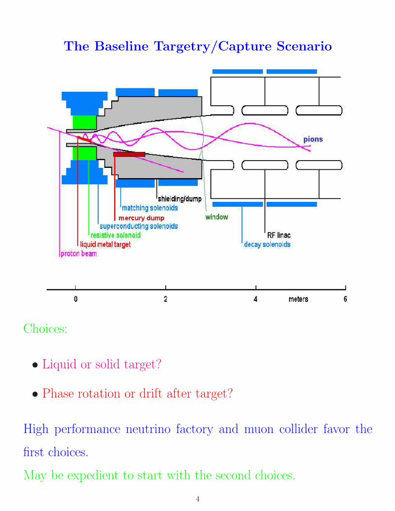
The Baseline Targetry/Capture Scenario
Choices:
• Liquid or solid target?
• Phase rotation or drift after target?
High performance neutrino factory and muon collider favor the
first choices.
May be expedient to start with the second choices.
4
Two Classes of Issues
1. Viability of targetry and capture for a single pulse.
• Effect of pressure wave induced in target by the proton
pulse.
• Interaction of a moving metal target with the solenoid field.
• Operation of the first rf cavity in a magnetic field and in
large particle flux.
2. Long-term viability of the system in a high radiation area.
[Issues for solid target & magnet coils are of this type.]
The most novel issues (1) are addressable in studies with low rep.
rate but a large number of protons/pulse (up to 1014 ppp in BNL
E951).
Long-term issues, including solid targets, may require study in a
high-rep.-rate, high-average-power beam (Los Alamos Spallation
Radiation Damage Facility, 0.8 MW, 20 Hz; a DOE Category 3
Nuclear Facility).
5
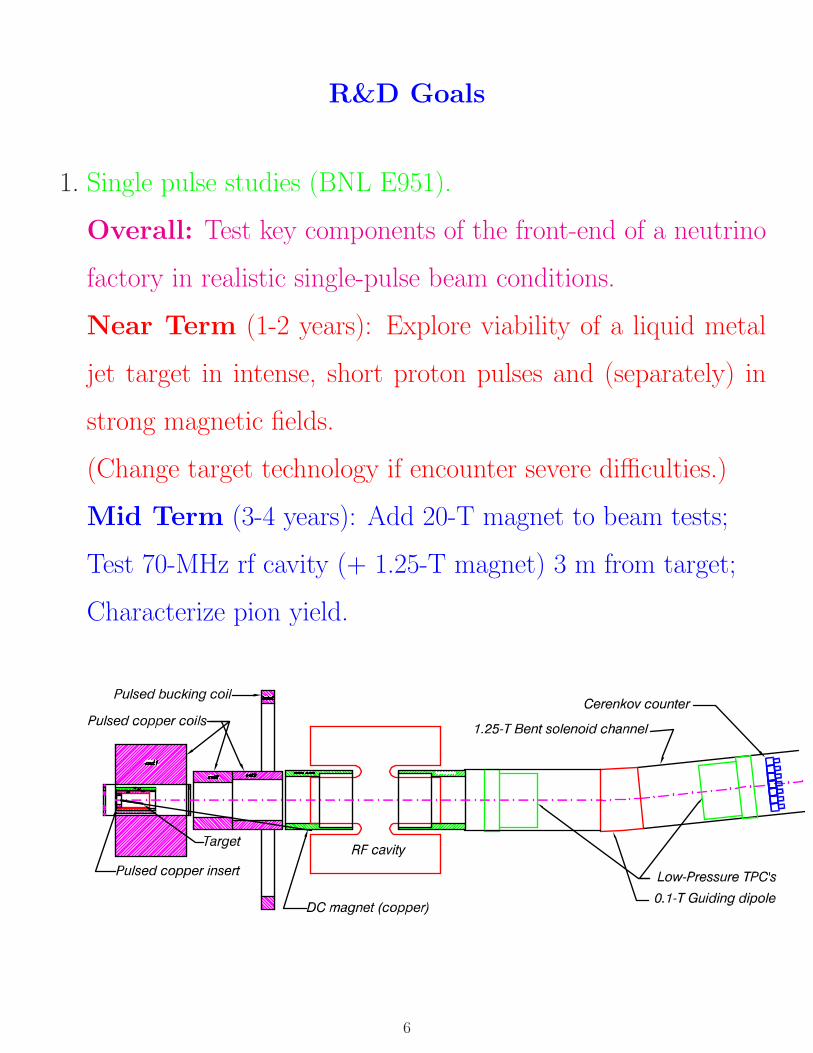
R&D Goals
1. Single pulse studies (BNL E951).
Overall: Test key components of the front-end of a neutrino
factory in realistic single-pulse beam conditions.
Near Term (1-2 years): Explore viability of a liquid metal
jet target in intense, short proton pulses and (separately) in
strong magnetic fields.
(Change target technology if encounter severe difficulties.)
Mid Term (3-4 years): Add 20-T magnet to beam tests;
Test 70-MHz rf cavity (+ 1.25-T magnet) 3 m from target;
Characterize pion yield.
6
2. Long Term Survivability
Define needed R&D program during 2nd half of
FY00.
Example: survival of a carbon target:
• Cylindrical geometry focuses reflected pressure wave to very
high values on axis, even for diffuse energy deposition.
• 10-100 J/gm/pulse, > 108 pulse/year,⇒> 105 eV/atom/yr.
• ⇒ Every interatomic bond broken >∼ 103 times/year.
• 4 MW ⇒ 1022 p/year ≈ 30 dpa/year.
• Graphite lifetime is about 10 dpa.
90% of beam energy deposited in the liner of the
superconducting magnets.
Is a solid liner viable; should the beam hit a mercury pool?
Are the superconducting coils viable? (Peter Wanderer,
Al Zeller)
We must operate a high-radiation facility. (Michael Todosow,
Phil Spampinato)
7
The 8 Steps in the E951 R&D Program
1. Simple tests of liquid (Ga-Sn, Hg) and solid (Ni) targets with
AGS Fast Extracted Beam (FEB).
2. Test of liquid jet entering a 20-T magnet (20-MW cw Bitter
magnet at the National High Magnetic Field Laboratory).
3. Test of liquid jet with 1014 ppp via full turn FEB (without
magnet).
4. Add 20-T pulsed magnet (4-MW peak) to liquid jet test with
AGS FEB.
5. Add 70-MHz rf cavity downstream of target in FEB.
6. Surround rf cavity with 1.25-T magnet. At this step we have
all essential features of the source.
7. Characterize pion yield from target + magnet system with slow
extracted beam (SEB).
8. Ongoing simulation of the thermal hydraulics of the liquid-
metal target system.
8
E951 Schedule
• FY99:
Prepare A3 area;
Begin work on liquid jets, magnet systems, and rf systems.
• FY00:
Complete A3 line;
Continue work on magnet and rf systems;
Begin work on extraction upgrade.
• FY01:
First test of targets in A3;
Liquid jet test in 20-T magnet at NHMFL;
Continue work on extraction magnet and rf systems.
(600 hours).
9
• FY02:
Complete extraction upgrade, magnet and rf systems;
Test targets with 1014 ppp;
Begin work on pion yield diagnostics;
Option to study mercury dump in vertically pitched beam.
(600 hours).
• FY03:
Beams tests of target + 20-T pulsed magnet + rf cavity;
Complete pion detectors; test yield with low intensity SEB.
(1800 hours).
10
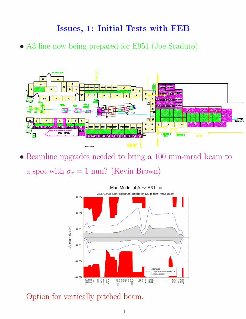
Issues, 1: Initial Tests with FEB
• A3 line now being prepared for E951 (Joe Scaduto).
• Beamline upgrades needed to bring a 100 mm-mrad beam to
a spot with σr = 1 mm? (Kevin Brown)
CF
010
CD
1 C
Q1
CQ
2 C
Q3
CF
039
AB
1
BB
3
AP
1 C
F10
0
AD
2 A
F12
4
AQ
5A
F17
1
AD
4A
D5
AD
6A
D7
AD
8A
D9
AF
237
A
Q6
AQ
7A
Q8
AQ
9
AT
GT
A3Q
1A
3Q2
A3Q
3A
3Q4
A3Q
5A
3Q6
A3Q
7A
3Q8
A3Q
9A
3TG
T
−0.05
−0.03
−0.01
0.01
0.03
0.05
1/2
beam
siz
e (m
)
Mad Model of A −> A3 Line25.5 GeV/c Non−Resonant Beam for 120 pi mm−mrad Beam
Apertures120 pi mm−mrad envelope1 sigma particle
Option for vertically pitched beam.
11
• Beamline instrumentation upgrades: spot size, beam current,
FEB radiation monitoring.
• Run first tests parasitic to g − 2 expt. in Oct/Nov 2000.
• Data taking via pulse-on-demand once every few minutes; but
desire 1-Hz running for beam tuning.
• Shielding needed for 1-Hz running with 1014 ppp = 100 TP
(Ripp Bowman, Ralf Prigl).
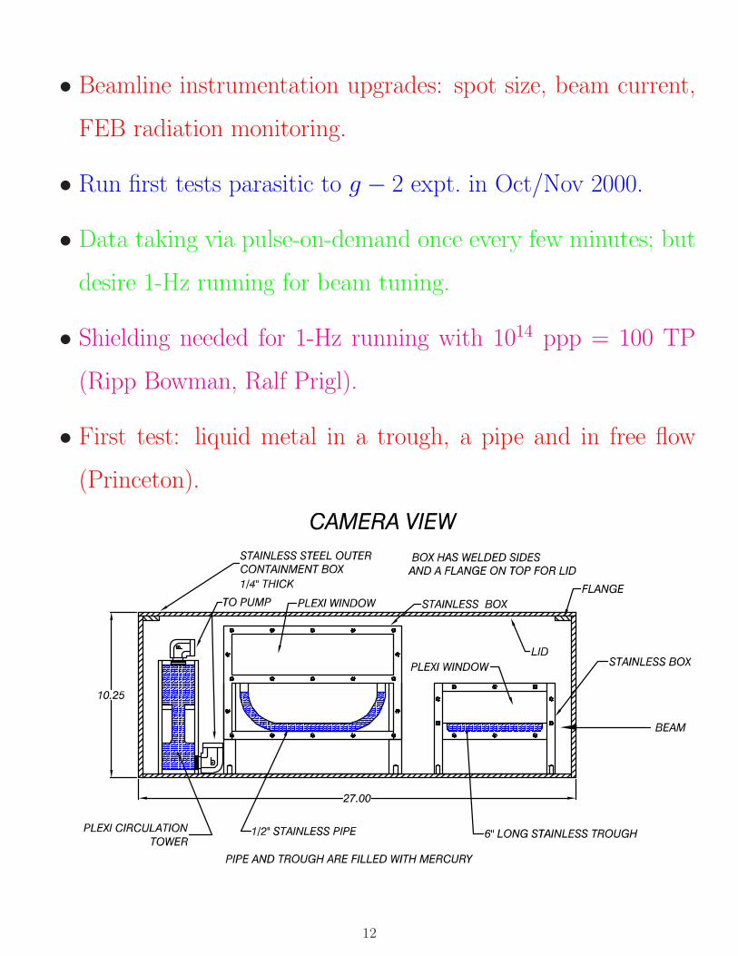
• First test: liquid metal in a trough, a pipe and in free flow
(Princeton).
12
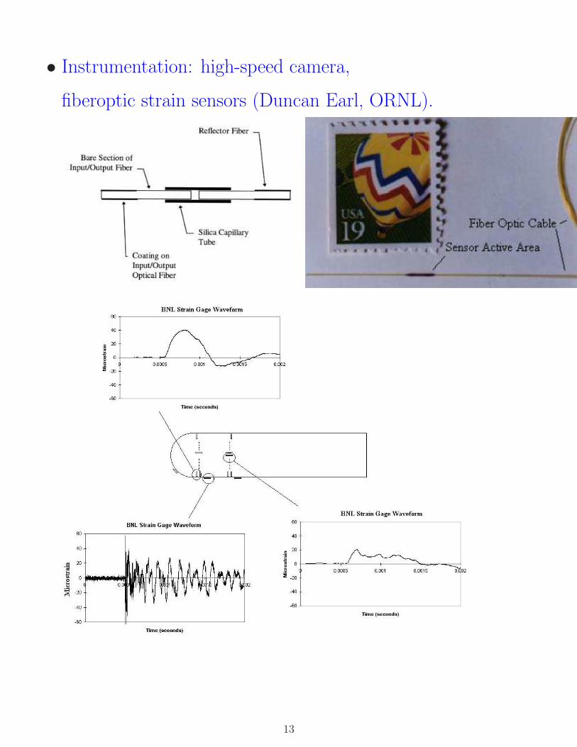
• Instrumentation: high-speed camera,
fiberoptic strain sensors (Duncan Earl, ORNL).
13
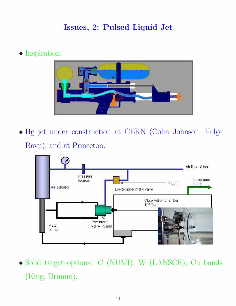
Issues, 2: Pulsed Liquid Jet
• Inspiration:
• Hg jet under construction at CERN (Colin Johnson, Helge
Ravn), and at Princeton.
• Solid target options: C (NUMI), W (LANSCE), Cu bands
(King, Drumm).
14
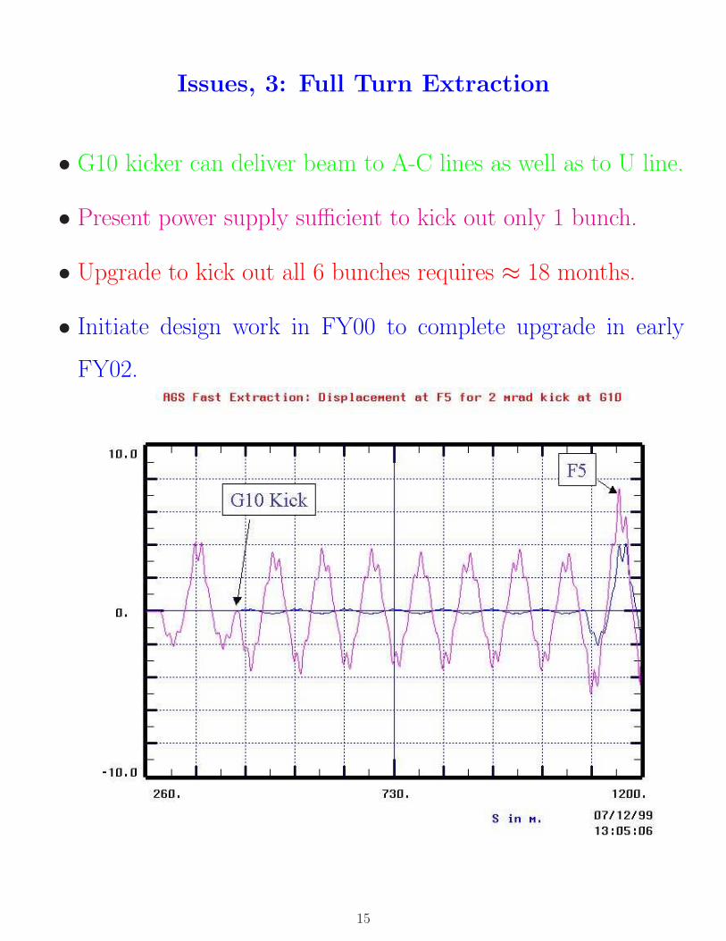
Issues, 3: Full Turn Extraction
• G10 kicker can deliver beam to A-C lines as well as to U line.
• Present power supply sufficient to kick out only 1 bunch.
• Upgrade to kick out all 6 bunches requires ≈ 18 months.
• Initiate design work in FY00 to complete upgrade in early
FY02.
15
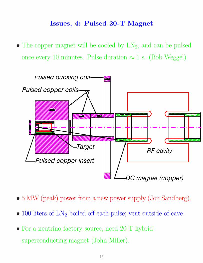
Issues, 4: Pulsed 20-T Magnet
• The copper magnet will be cooled by LN2, and can be pulsed
once every 10 minutes. Pulse duration ≈ 1 s. (Bob Weggel)
• 5 MW (peak) power from a new power supply (Jon Sandberg).
• 100 liters of LN2 boiled off each pulse; vent outside of cave.
• For a neutrino factory source, need 20-T hybrid
superconducting magnet (John Miller).
16
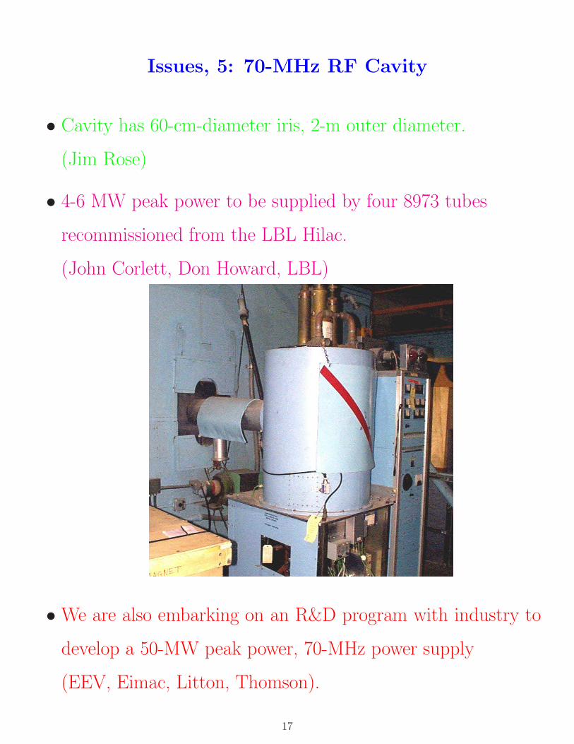
Issues, 5: 70-MHz RF Cavity
• Cavity has 60-cm-diameter iris, 2-m outer diameter.
(Jim Rose)
• 4-6 MW peak power to be supplied by four 8973 tubes
recommissioned from the LBL Hilac.
(John Corlett, Don Howard, LBL)
• We are also embarking on an R&D program with industry to
develop a 50-MW peak power, 70-MHz power supply
(EEV, Eimac, Litton, Thomson).
17
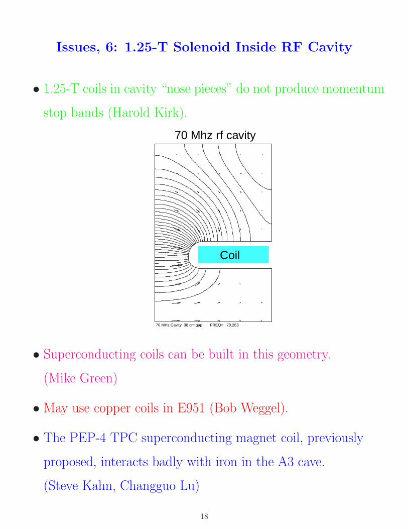
Issues, 6: 1.25-T Solenoid Inside RF Cavity
• 1.25-T coils in cavity “nose pieces” do not produce momentum
stop bands (Harold Kirk).
70 MHz Cavity 38 cm gap FREQ= 70.263
70 Mhz rf cavity
Coil
• Superconducting coils can be built in this geometry.
(Mike Green)
• May use copper coils in E951 (Bob Weggel).
• The PEP-4 TPC superconducting magnet coil, previously
proposed, interacts badly with iron in the A3 cave.
(Steve Kahn, Changguo Lu)
18
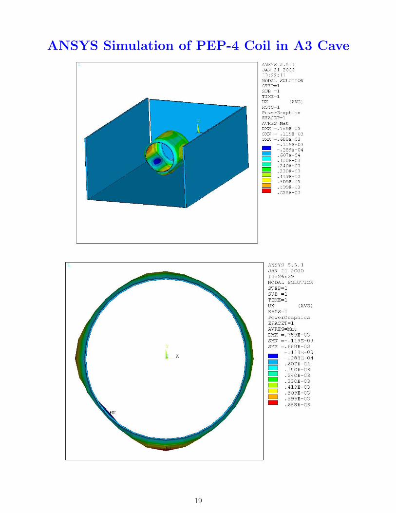
ANSYS Simulation of PEP-4 Coil in A3 Cave
19
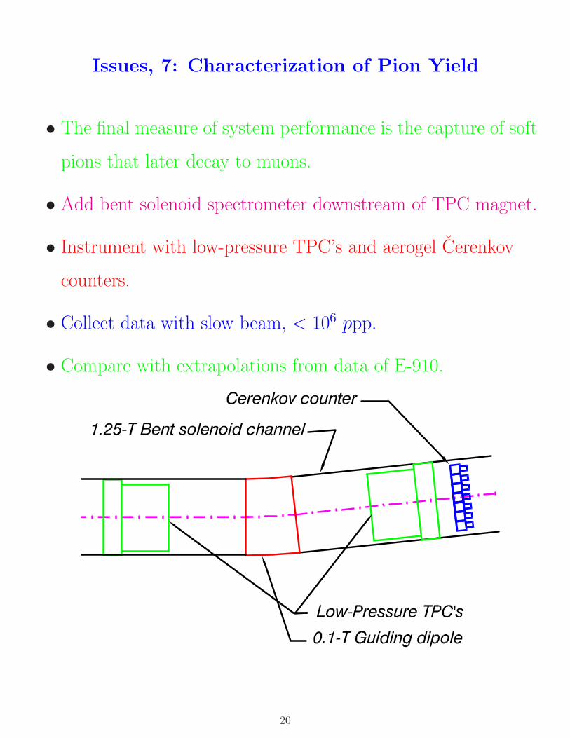
Issues, 7: Characterization of Pion Yield
• The final measure of system performance is the capture of soft
pions that later decay to muons.
• Add bent solenoid spectrometer downstream of TPC magnet.
• Instrument with low-pressure TPC’s and aerogel Cerenkov
counters.
• Collect data with slow beam, < 106 ppp.
• Compare with extrapolations from data of E-910.
20
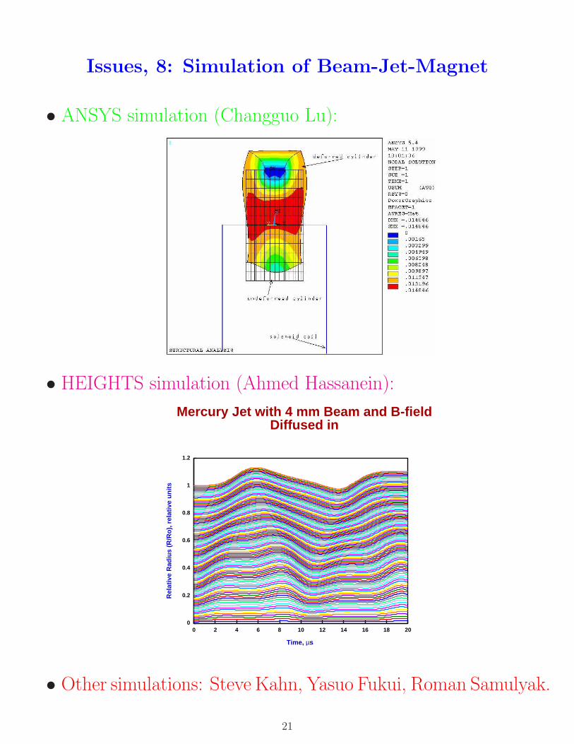
Issues, 8: Simulation of Beam-Jet-Magnet
• ANSYS simulation (Changguo Lu):
• HEIGHTS simulation (Ahmed Hassanein):
0
0.2
0.4
0.6
0.8
1
1.2
0 2 4 6 8 10 12 14 16 18 20
Rel
ativ
e R
adiu
s (R
/Ro
), r
elat
ive
un
its
Time, µs
Mercury Jet with 4 mm Beam and B-fieldDiffused in
• Other simulations: Steve Kahn, Yasuo Fukui, Roman Samulyak.
21


![Targetry and radiochemistry for no-carrier-added ... · Targetry and radiochemistry for no-carrier-added production of 117,118m,119,120m,122Sb 11 [9] and Thisgaard et al. [28, 31],](https://img.pdfslide.net/doc/110x75/5e4063814ddf42674002d5fe/targetry-and-radiochemistry-for-no-carrier-added-targetry-and-radiochemistry.jpg)

![Neutrino Beams From Electron Capture at High Gamma · like superbeam experiments [35–40], neutrino factories [41–49], and beta-beams [50–63]. Recently, another idea has been](https://img.pdfslide.net/doc/110x75/5f5d8e5003da4e77d3467697/neutrino-beams-from-electron-capture-at-high-gamma-like-superbeam-experiments-35a40.jpg)