Embed Size (px)
Citation preview
r ".-iSiV • vmvmimmm^mmmmmi*miimnmmmmmiK0NKSM&
ARPA ORDER NO : 189-1
OS O
AC (M
R-753-ARPA
April 1971
THE RAND VIDEO GRAPHIC SYSTEM AN APPROACH TO A GENERAL
USER-COMPUTER GRAPHIC COMMUNICATION SYSTEM
K. W. Uncapher
A Report prepared for
ADVANCED RESEARCH PROJECTS AGENCY Reproduced by
NATIONAL TECHNICAL INFORMATION SERVICE
Springfield, Va. 22151
D D.Sh^ Rand iH
JUN16 WTt
— c
SANTA MONICA CA 90406
5V
fm*y®m$mmmmsig^ig$$;f' ^'mw^w^*
DOCUMENT CONTROL DATA
I. ORIGINATING ACTIVITY
The Rand Corporation
2a. REPORT SECURITY ClASSIFICATION
UNCLASSIFIED 2b. GROUP
3. REPORT TITLE
THE RAND VIDEO GRAPHIC SYSTEM - A APPROACH TO A GENERAL USER-COMPUTER GRAPHIC COMMUNICATION SYSTEM
4. AUTHOR(S) (latt name, first name, initial)
Uncapher, K. W.
S. REPORT DATE
April 1971 6a. TOTAL NO. OF PAGES
20 6b. NO. OF REFS.
7. CONTRACT OR GRANT NO.
DAHC15 67 C 0141
8. ORIGINATOR'S REPORT NO.
R-753-ARPA
9a. AVAILABILITY/LIMITATION NOTICES
DDC-1
9b. SPONSORING AGENCY
Advanced Research Projects Agency
10. ABSTRACT 11. KEY WORDS
\ -i»
A report prepared for the AGARD Avionics Panel Technical Symposium on Data Handling Devices, Istanbul, Turkey, 1-4 June 1970. Cathode-ray-tube graphic displays offer one of the most powerful and useful man- machine communication paths. The Rand Video Graphic System offers one implementa- tion. It serves 32 consoles; each has a full range of Interaction and full graphics, and accommodates up to 8 differ- ent Input devices. Each console serves as the general graphic terminal for all the user's computer-based needs. The user cau access several computers from any terminal. The system is based on the use of 873-llne TV monitor in each terminal. Scan conver- sion and buffered stor?ge are (_'int rail zed to Improve performance and reduce cost. The report describes system components, operating environment, hardware and soft- ware, consoles, and reliability and per- formance. An all-digital approach to the video system is now being designed at Rand.
Video Graphic System Computer Graphics Computer-Aided Design
'^^mmmi^mmmmmam
■ •--^.. .
•:, . i
.
SSaBBW "' -rung w Bumfci. v«.; ,,,3i!WW*»!i«M*>«i»«"i«(p|w
v. ■ - ■■ ■■■■:■:'■■'::■■■■:■■ ■'-,•■ ■.;:,,i,,..-~.-, . ■ .,, „ ^ .
MKPA ORDER NO.; 189-1
R-753-ARPA
April 1971
THE RAND VIDEO GRAPHIC SYSTEM AN APPROACH TO A GENERAL
USER-COMPUTER GRAPHIC COMMUNICATION SYSTEM
K. W. Uncapher
Defaffö bf Irtustraiions uP this document may be bett'';1
studied ':r r-'^-r'^],,
A Report prepared for
ADVANCED RESEARCH PROJECTS AGENCY
Rand SANTA MONICA. CA 90406
THIS DOCUMENT HAS BEEN APPROVED FOR PUBLIC RELEASE AND SALE; ITS DISTRIBUTION IS UNLIMITED.
■ ■• . . . ■ .
»•■ -v
Rand maintains a number of special subject bibliographies containing abstracts of Rand publications in fields of wide current interest. The following bibliographies are available upon request:
Africa • Arms Control • Civil Defense • Combinatorics Communication Satellites • Communication Systems • Communist China
Computing Technology» Decisionmaking • Delphi» East-West Trade Education • Foreign Aid • Foreign Policy Issues * Game Theory
Health-related Research • Latin America • Linguistics • Maintenance Mathematical Modeling of Physiological Processes • Middle East
Policy Sciences • Pollution • Program Budgeting SIMSCRIPT and Its Applications • Southeast Asia • Systems Analysis
Television • Transportation • Urban Problems • USSR/East Europe Water Resources • V/eapon Systems Acquisition
Weather Forecasting and Control
To obtain copies of these bibliographies, and to receive information on how to obtain copies of individual publications, write to: Communications Department, Rand, 1700 Main Street, Santa Monica, California 90406.
Published by The Rand Corporation
• v.-«^««w„„..
PREFACE
This report was prepared for the XXth AGARD* Avionics Panel Technical Symposium on Data Handling Devices held in Istanbul, Turkey, June 1-4,1970. The focus is on general system information that is important to the user. Technical detail and technical jargon have been avoided to assist the noncomputer specialist in understanding the significant advantages of the video approach to computer graph- ics.
T. 0. Ellis of Rand is responsible for a major part of the total system design. The Image Distribution System portion of the system was acquired under a subcon- tract with IBM, Los Gatos. Harold Martin was project engineer on the IDS.
'Advisory Group for Aerospace Research and Development.
ill
,.^!t^««Mra^m«^**^«^wi^^ -.-.■■■■
CONTENTS
PREFACE iii
INTRODUCTION 1
THE OPERATING ENVIRONMENT 2
THE VIDEO GRAPHIC SYSTEM DESCRIPTION 2
THE CONSOLES 5
SYSTEM PERFORMANCE 8
SYSTEM RELIABILITY, LIMITATIONS, AND PROBLEMS 9
SYSTEM USE 10
SOFTWARE 12 Video Message Handler (VMH) 13 Integrated Graphics System (IGS) 13 1800 Software 13
CONCLUDING REMARKS 14
REFERENCES 15
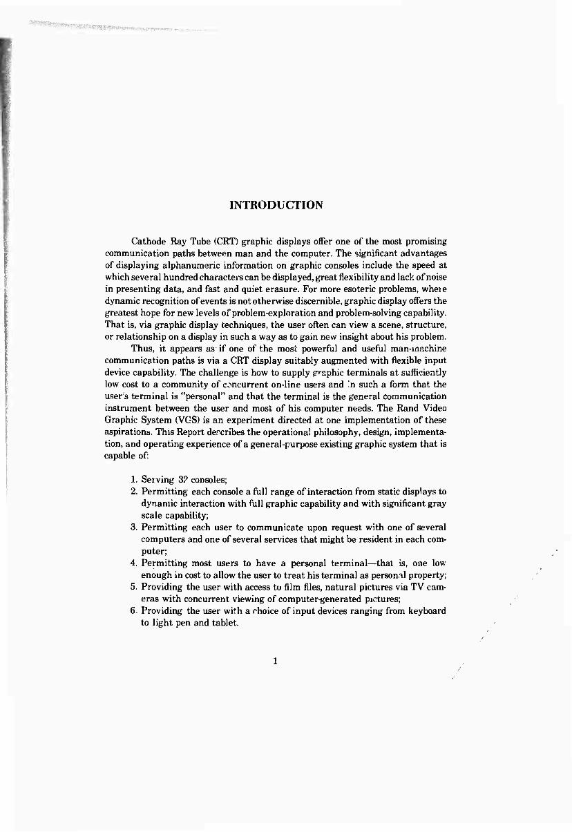
INTRODUCTION
Cathode Ray Tube (CRT) graphic displays offer one of the most promising communication paths between man and the computer. The significant advantages of displaying alphanumeric information on graphic consoles include the speed at which several hundred characters can be displayed, great flexibility and lack of noise in presenting data, and fast and quiet erasure. For more esoteric problems, whei e dynamic recognition of events is not otherwise discernible, graphic display offers the greatest hope for new levels of problem-exploration and problem-solving capability. That is, via graphic display techniques, the user often can view a scene, structure, or relationship on a display in such a way as to gain new insight about his problem.
Thus, it appears as if one of the most powerful and useful man-machine communication paths is via a CRT display suitably augmented with flexible input device capability. The challenge is how to supply graphic terminals at sufficiently low cost to a community of concurrent on-line users and 'n such a form that the user s terminal is "personal" and that the terminal is the general communication instrument between the user and most of his computer needs. The Rand Video Graphic System (VGS) is an experiment directed at one implementation of these aspirations. This Report dercribes the operational philosophy, design, implementa- tion, and operating experience of a general-purpose existing graphic system that is capable of:
1. Serving 3? consoles; 2. Permitting each console a full range of interaction from static displays to
dynamic interaction with full graphic capability and with significant gray scale capability;
3. Permitting each user to communicate upon request with one of several computers and one of several services that might be resident in each com- puter;
4. Permitting most users to have a personal terminal—that is, one low enough in cost to allow the user to treat his terminal as personal property;
5. Providing the user with access to film files, natural pictures via TV cam- eras with concurrent viewing of computer-generated pictures;
6. Providing the user with a choice of input devices ranging from keyboard to light pen and tablet.
- ---awww^iiijiwi^^^^ mMmmm»mmmmmmmmmm
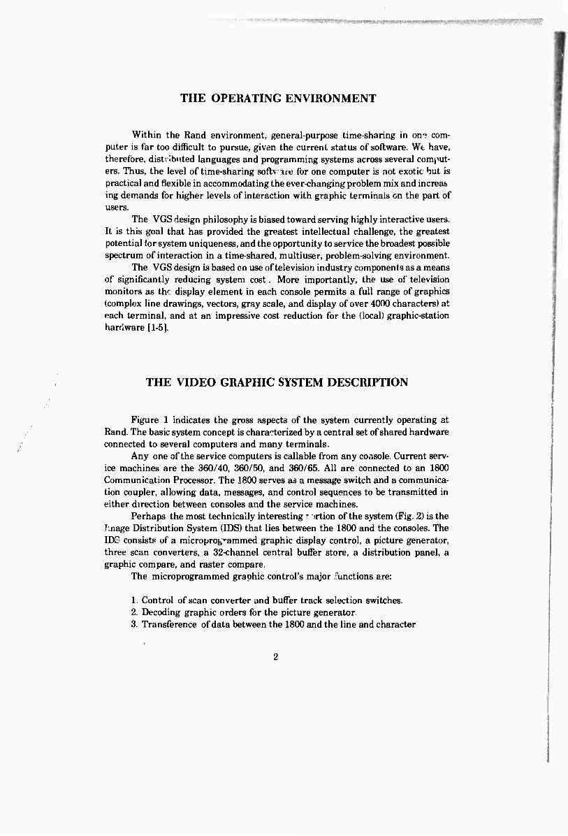
THE OPERATING ENVIRONMENT
Within the Rand environment, general-purpose time-sharing in on« com- puter is far too difficult to pursue, given the current status of software. Wt have, therefore, distributed languages and programming systems across several comput- ers. Thus, the level of time-sharing softv are for one computer is not exotic but is practical and flexible in accommodating the ever-changing problem mix and increa& ing demands for higher levels of interaction with graphic terminals on the part of users.
The VGS design philosophy is biased toward serving highly interactive users. It is this goal that has provided the greatest intellectual challenge, the greatest potential for system uniqueness, and the opportunity to service the broadest possible spectrum of interaction in a time-shared, multiuser, problem-solving environment.
The VGS design is based on use of television industry components as a means of significantly reducing system cost. More importantly, the use of television monitors as the display element in each console permits a full range of graphics (complex line drawings, vectors, gray scale, and display of over 4000 characters) at each terminal, and at an impressive cost reduction for the (local) graphic-station hardware [1-5].
THE VIDEO GRAPHIC SYSTEM DESCRIPTION
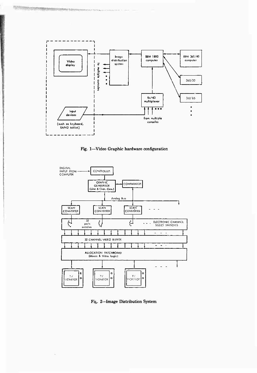
Figure 1 indicates the gross aspects of the system currently operating at Rand. The basic system concept is characterized by a central set of shared hardware connected to several computers and many terminals.
Any one of the service computers is callable from any console. Current serv- ice machines are the 360/40, 360/50, and 360/65. All are connected to an 1800 Communication Processor. The 1800 serves as a message switch and a communica- tion coupler, allowing data, messages, and control sequences to be transmitted in either direction between consoles and the service machines.
Perhaps the most technically interesting r irtion of the system (Fig. 2) is the linage Distribution System (IDS) that lies between the 1800 and the consoles. The IDS consists of a microprogrammed graphic display control, a picture generator, three scan converters, a 32-channel central buffer store, a distribution panel, a graphic compare, and raster compare.
The microprogrammed graphic control's major functions are:
1. Control of scan converter and buffer track selection switches. 2. Decoding graphic orders for the picture generator 3. Transference of data between the 1800 and the line and character
S^WWHBS'Ki^W
r
Image distribution
system
I8M 1600 computer
IBM 360/40
computer Video display 1 °
| | 1 "ö-
• • •
\
\
1 " o
1 § 360/50
1 ^ 1 " 1 1
RAND multiplexor
360/65
2 (
1 1 1
/ Inpuf / devices /
1 • • • •
' i 1 1 1
from multiple
uch as keyboarc
RAND tablet)
consoles
._J
Fig. 1—Video Graphic hardware configuration
DIGITAL INPUT FROM ■ COMPUTER
CONTROLLER
GRAPHIC GENERATOR
(Line & Chor. Gen.)
SCAN CONVERTER
7f
COMPARATOP.
Analog Buss
SCAN CONVERTER
SCAN CONVERTER
32 pos'n • /
switclics •
ELECTRONIC CHANNEL SELECT SWITCHES
32 CHANNEL VIDEO BUFFER
TT ALLOCATION PATCHBOARD
(Mixers & Video Logic)
— *
Ty 'V.ONITOR
C
O TV
MONITOR
O
O TV
MOKITO1;
0
o
Fig,. 2—Image Distribution System
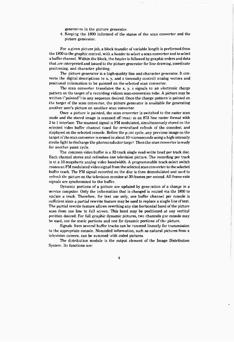
generators in the picture generator. 4. Keeping the 1800 informed of the status of the scan converter and the
picture generator.
For a given picture job, a block transfer of variable length is performed from the 1800 to the graphic control, with a header to select a scan converter and to select a buffer channel. Within the block, the header is followed by graphic orders and data that are interpreted and issued to the picture generator for line drawing, coordinate positioning, and character plotting.
The picture generator is a high-quality line and character generator. It con- verts the digital descriptions to x, y, and z (intensity control) analog vectors and positional information to be painted on the selected scan converter.
The scan converter translates the x, y, z signals to an electronic charge pattern on the target of a recording vidicon scan-conversion tube. A picture may be written ("painted") in any sequence desired. Once the charge pattern is painted on the target of the scan converter, the picture generator is available for generating another user's picture on another scan converter.
Once a picture is painted, the scan converter is switched to the raster scan mode and the stored image is scanned off (read) in an 873 line raster format with 2 to 1 interlace. The scanned signal is FM modulated, simultaneously stored on the selected video buffer channel (used for centraJized refresh of the consoles), and displayed on the selected console. Before the p änt cycle, any previous image on the target ofthe scan converter is erased in about 10 microseconds using a high-intensity strobe light to discharge the photoconductor target. Then the scan converter is ready for another paint cycle.
The common video buffer is a 32-track single read-write head per track disc. Each channel stores and refreshes one television picture. The recording per track is at a 10-megahertz analog video bandwidth. A programmable track-select switch routes an FM modulated video signal from the selected scan converter to the selected buffer track. The FM signal recorded on the disc is then demodulated and used to refresh thf picture on the television monitor at 30 frames per second. All frame-rate signals are synchronized to the buffer.
Dynamic portions of a picture are updated by generation of a change in a service computer. Only the information that is changed is routed via the 1800 to upu'ate a track. Therefore, for text use only, one buffer channel per console is sufficient since a partial rewrite feature may be used to replace a single line of text. The partial rewrite feature allows rewriting any size horizontal band ofthe picture scan from one line to full screen. This band may be positioned at any vertical position desired. For full graphic dynamic pictures, two channels per console may be used, one for static portions and one for dynamic portions of the picture.
Signals from several buffer tracks can be summed linearly for transmission to the appropriate console. Noncoded information, such as natural pictures from a television camera, can be summed with coded pictures.
The distribution module is the output element of the Image Distribution System. Its functions are:
1. To connect consoles to the appropriate IDS channel. 2. To linearly mix, if desired, both signals from several buffer channels and
noncoded, or recorded, information.
In certain types of graphic applications, it is desirable for the system hard- ware to be able to examine a picture to determine if any visible elements occur in a certain area of the display. This function is called graphic compare. It allows a program to detect the presence and identity of an image element within a variable program-defined rectangular "window" within the display area. The system can perform this test with or without concurrent track rewrite.
The raster compare function compares the video from one buffer channel with that from another to see if there are points on the picture where both have video information. This function was built in for experimental purposes only. For example, it will be used for complex scanning of natural pictures, wherein a comput- er-generated picture is compared with a natural image to derive coincidence infor- mation. The resultant information could be returned to the service machine for further control of the comparison picture.
Each terminal is connected via a pair of coax cables to an I/O multiplexor. One coax carries all signals (video, digital data, and audio) to the terminal, and another cable carries an identical format from the terminal to the central equip- ment, allowing full duplex communication with the terminals.
All station cables are terminated in an interface unit built by Rand that combines the signals on each outgoing coax and separates the signals incoming from the station. All of the incoming digital information is multiplexed into one of two 1800 read channels, depending on the data type. All outgoing data are demulti- plexed from a single 1800 write channel.
Normal use of the Rand Tsblet with any display system requires a plotted point in the display to continuously reflect the relative stylus position on the tablet. This function, called direct feedback, is performed in hardware in the Video Graphic System. The pen coordinates are equated to a time position in the television raster scan by synchronizing clock-driven counters to the rastersweep sync pulses. This produces a pulse in each field scan that is added to the video signal displayed by the station monitor.
THE CONSOLES
Each console is designed to be the personal property of each user. That is, each is low enough in cost to be a justifiable expense for a person with moderate to heavy use rates. Consoles are designed to operate in the user's most productive problem-solving environment—his office. Each console is connected to the distribu- tion module via two coax cables up to 2500 ft et long.
.■ ■ ■■■ ■ Wi
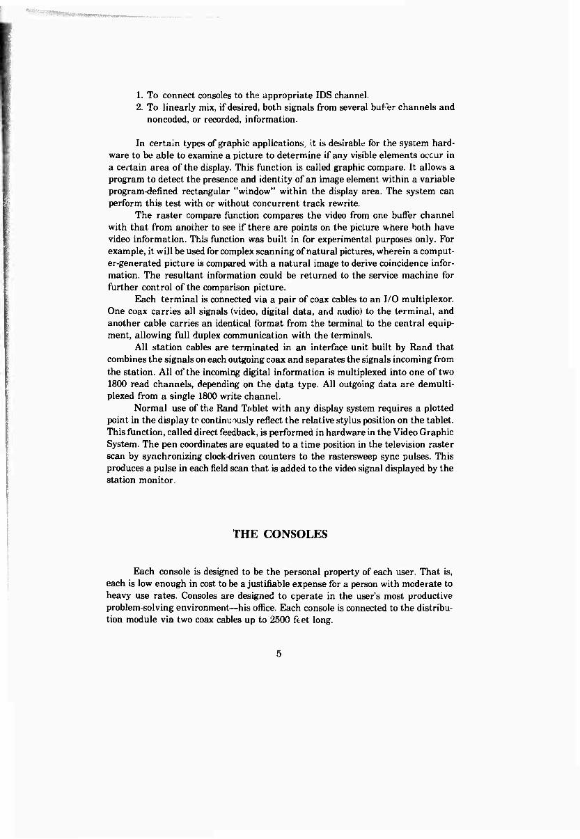
Figure 3 is a block diagram of the console. Each console modem allows the user a choice of up to eight input devices; thus, the user has input flexibility to match the output flexibility of graphically displayed information. Currently available in- put devices are a Selectric keyboard (standard on all consoles), a Rand Tablet, a Graf Pen tablet, a light pen, and a fan-out device that will accommodate up to 64 simple data entry keyboards per station. Each console has a full duplex audio that allows the user either to communicate to other machine operators or consoles, or to hear on his station audio portions of regular or closed circuit telecasts.
rvzx VIDEO
Coax
from System
Coax
to Sytttm
(Video, Data, & Audio each way)
OUT
£2*
Modem
VIDEO IN
Camera, Lightpen,
etc.
- Up tc 8 Devices
"SYSI5M CONTROLS"
Speaker-Mike Press-to-to Ik Sw. Power ON/OFF Log ON/OfF System "ON AIR" Light Interrupt Button
Keylock Tab/Back-lab 3 Cases Print I Case Functions
LOOPING DEVICE CABLE Address Out I Bit Serial Data Out Demand IN/RESPONSE 8 Bit + P Data In
Fig. 3—Video Graphic station configuration
The keyboard has upper/lower case, a third case for special symbols, and a fourth case for user-described function keys. Each console has control buttons and lights to keep the user constantly informed of the following station conditions:
1. Station power switch and light; 2. System ready light; 3. Connect button (log on);
4. Station on-line light; 5. Disconnect button (log off).
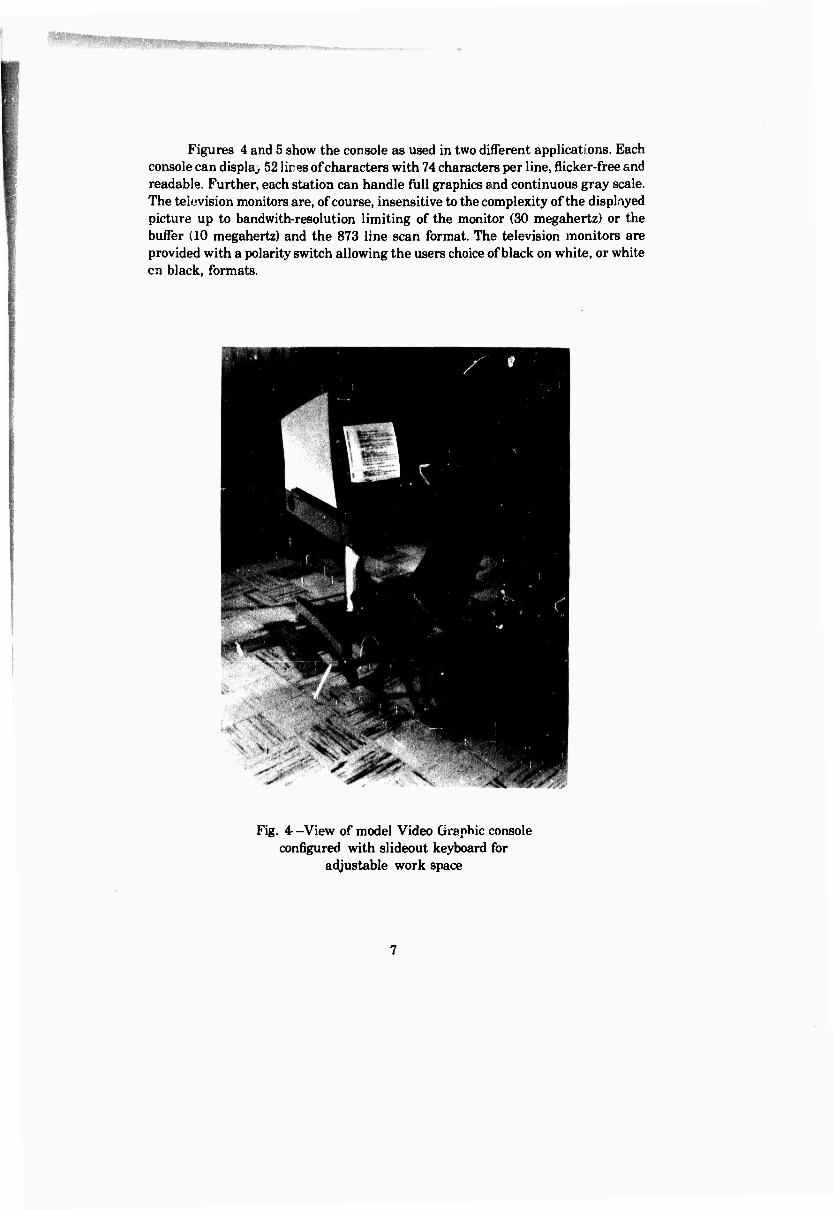
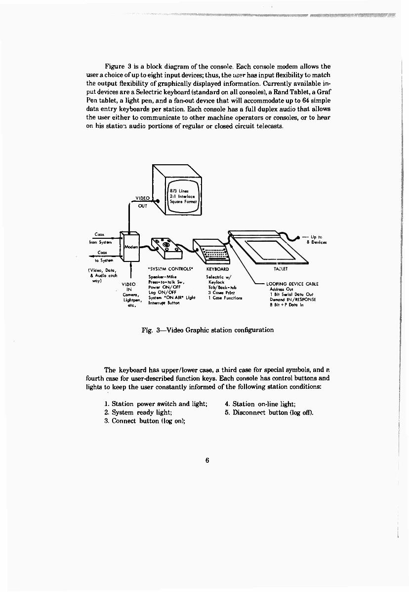
Figures 4 and 5 show the console as used in two different applications. Each console can display 52 lires of characters with 74 characters per line, flicker-free and readable. Further, each station can handle full graphics and continuous gray scale. The television monitors are, of course, insensitive to the complexity of the displayed picture up to bandwith-resolution limiting of the monitor (30 megahertz) or the buffer (10 megahertz) and the 873 line scan format. The television monitors are provided with a polarity switch allowing the users choice of black on white, or white en black, formats.
Fig. 4 -View of model Video Graphic console configured with slideout keyboard for
adjustable work space
Fig. 5—Video Graphic console with tablet on keyboard work space
SYSTEM PERFORMANCE
The major design criteria enable the system to be sufficiently responsive and sharable that any of several concurrent users can utilize an interaction capacity appropriate to the problem. The averaging power of concurrent users allows appro- priate economic sharing of the hardware. Uniform line-widths, uniform brightness, and line closure are important, and are state of the art.
Average character-generation time is 14 microseconds. Vector-paint time varies between 10 and 100 microseconds with a maximum depending on the vector length.
The picture generator will execute graphic orders at about an average of 70K bytes/sec. The paint time of the scan converter is a function of picture complexity, but averages 10 milliseconds. The upper limit of the scan converter storage time is about 700 milliseconds allowing very complex pictures to be written. Since flicker rate is unrelated to paint time, there are essentially no picture-programming restric- tions imposed on the users.
System performance with three scan converters will support eight to ten highly interactive stations, each with unlimited input rate from tablets. The system can theoretically support over 150 stations operating only with keyboard text in- teraction. Of coarse, video buffer storage would have to be added for lefreshing of pictures beyond the present 32-console limit. One would expect many environments to support dynamically some appropriate mix because even tnose demanding high interaction rates actually use their "racing stripes" a small percentage of the time. Currently, 25 stations are available for convenient use.
SYSTEM RELIABILITY, LIMITATIONS, AND PROBLEMS
The Video Graphic System was installed at Rand in October 1968. It has been operational virtually 24 hours a day, 7 days a week, since installation. The overall reliability has been remarkably goo^. considering the analog nature of some of the hardware. Downtime has been trivial and maintenance requirements minimum. Preventative naintenance is limited mainly to a weekly check of sea. onverter adjustments for scan converter aging.
The 10-megahertz bandwidth per channel is the limiting factor in terms of system resolution and picture quality. To bring the system into balance from a system resolution standpoint, the buffer frequency should be 20 megahertz to match the limitation of scan converters. All other components, including the monitors, have a basic limit of 30 megahertz.
The buffer has two basic problems that must be solved for optimum, continu- ous tone-picture use. These are:
1. Low signal-to-noise ratio in some tracks mainly due tc incomplete erasure of previously written information. There is a need for either a separate erase head or a better erase with the present heads. This condition is achievable, but only through careful analysis and redesign of the head, and possibly the recording medium.
2. Detectable track-to-track interference during a write operation for some channels in the video buffer. Analysis has not yet determined enough about the source of the problem to suggest a solution.
SYSTEM USE
Thus far, most of the VGS use has been to support users performing research in man-machine communication. Thus, the VGS ability to provide real-time re- sponse of machine interpretation of human gestures (via Rand Tablet stylus-input device) is vital. This capability is used for such things as real-time automatic hand- printed character recognition, and to supply highly responsive full-graphic editing. However, the computer researcher and the programming staffof the Rand Computa- tion Center also need remote job entry, program debugging, and program editing. These functions are currently supplied to users via IBM's CPS, retrofitted with a graphic interface (keyboard input and graphic display output), and a general- purpose editor called Simultaneous Graphic System (SGS).
In addition, the VGS is used extensively where problem-solving is enhanced by the use of superimposed computer-generated pictures and noncoded information from a television camera.
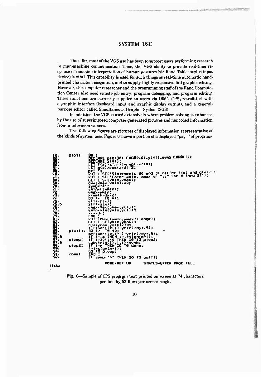
The following figures are pictures of displayed information representative of the kinds of system uses. Figure 6 shows a portion of a displayed "pag " of program-
irst
pietf
ptottt:
piuop:
piop2:
don«:
gfctflRC p(0:30) Cl OeCLARC x(UI):
CHRR(UO).y(«tn.«yi*> CMRRCI);
)( -x/10),
PUT LfSTCStatewants 30 and 31 PUT LISTC'Enter xjwtn, ttman or GET UST(M»rn.Mi«aM); dx« (xnax-xm t n)/U 0; syMb''**; yfcrn«F(xmtn); ymax'vmln; DO t * I TO 31;
deffn« Hx> and « '.," for 0 thru 2
I(I»).
y(rW( Hr)'q(
x)\ •g(x){
ymax'max(ymaK>y(•)); yrnfrcir InCymtn.yC t) »; M'kt-dx; END • PUT lMflr.C(yinIn,yinaM}('mane); GET UIST(yMfn,ymax); dy-(ymax-ymfn)/30; I-floor<(t(l)-ymtn)/dy».5); DO t--l TO 40; m*f toor ((x( 1*1 )-ymln) /dy«-.5); IF I—w THEN l--(*«jfqn(m'0; IF l'30l(<0 THEN GO TO plop2; substr<o(I).t.))'symb; IT i^m THEN CO TO done; I-«! »sfandii-l); GO TO ploop; END ; K H
IT ^ymb-'o* THEN co TO putrt; HOOE'REF UP STftTUS«UPPER PRCE FULL
Fig. 6—Sample of CPS program text printed on screen at 74 characters per line by(52 lines per screen height
10
■ ■
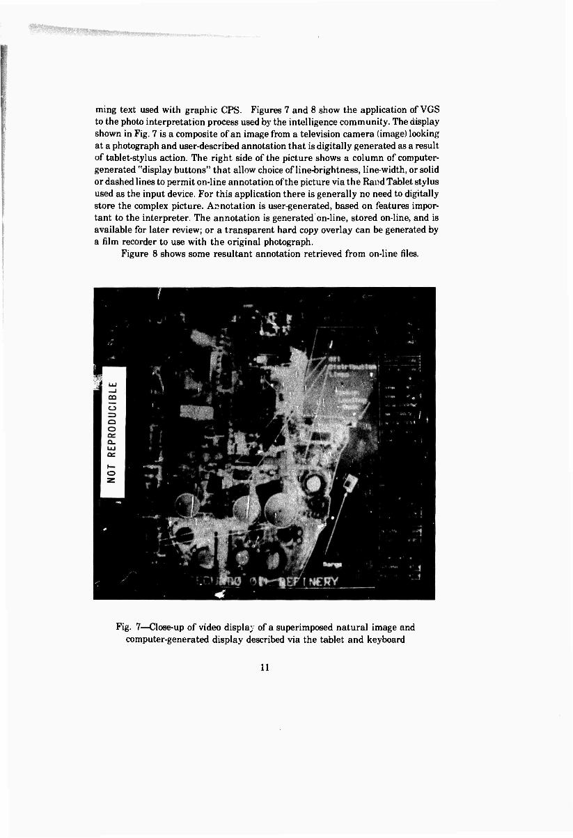
ming text used with graphic CPS. Figures 7 and 8 show the application of VGS to the photo interpretation process used by the intelligence community. The display shown in Fig. 7 is a composite of an image from a television camera (image) looking at a photograph and user-described annotation that is digitally generated as a result of tablet-stylus action. The right side of the picture shows a column of computer- generated "display buttons" that allow choice of line-brightness, line-width, or solid or dashed lines to permit on-line annotation of the picture via the Rand Tablet stylus used as the input device. For this application there is generally no need to digitally store the complex picture. Annotation is user-generated, based on features impor- tant to the interpreter. The annotation is generated on-line, stored on-line, and is available for later review; or a transparent hard copy overlay can be generated by a film recorder to use with the original photograph.
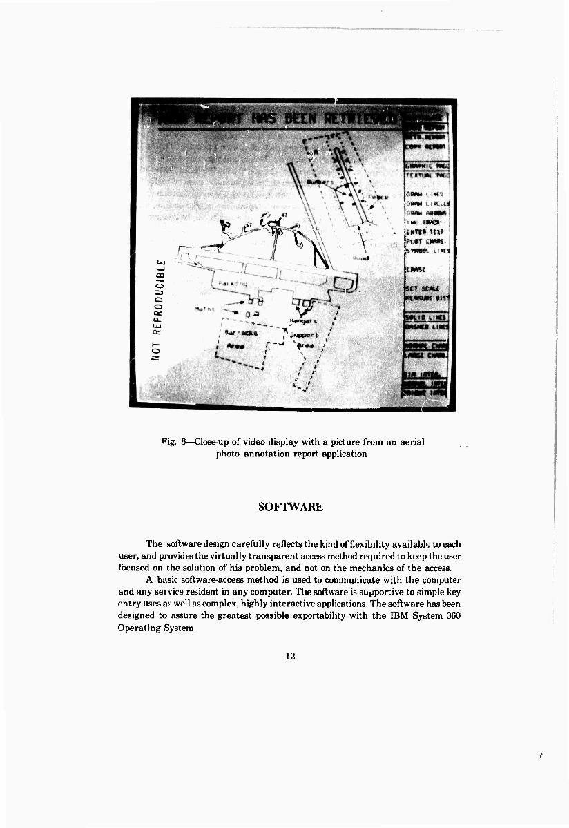
Figure 8 shows some resultant annotation retrieved from on-line files.
Fig. 7—Close-up of video display of a superimposed natural image and computer-generated display described via the tablet and keyboard
11
r--
CD
o
*4.
a»<M emu OBAn
I« IM«» pMHt tftt W.dT CM««.
j
str stmt I
Fig. 8—Close up of video display with a picture from an aerial photo annotation report application
SOFTWARE
The software design carefully reflects the kind of flexibility available to each user, and provides the virtually transparent access method required to keep the user focused on the solution of his problem, and not on the mechanics of the access.
A basic software-access method is used to communicate with the computer and any ser vice resident in any computer. The software is supportive to simple key entry uses as well as complex, highly interactive applications. The software has been designed to assure the greatest possible exportability with the IBM System 360 Operating System.
12
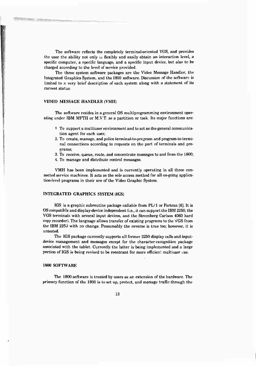
The software reflects the completely terminal-oriented VGS, and provides the user the ability not only to flexibly and easily obtain an interaction level, a specific computer, a specific language, and a specific input device, but also to be charged according to the level of service provided.
The three system software packages are the Video Message Handler, the Integrated Graphics System, and the 1800 software. Discussion of the software is limited to a very brief description of each system along with a statement of its current status.
VIDEO MESSAGE HANDLER (VMH)
The software resides in a general OS multiprogramming environment oper- ating under IBM MFTII or M.V.T. as a partition or task. Its major functions are:
1 To support a multiuser environment and to act as the general communica- tion agent for each user;
2. To create, manage, and police terminal-to-prcgram and program-to-termi- nal connections according to requests on the part of terminals and pro- grams;
3. To receive, queue, route, and concentrate messages to and from the 1800; 4. To manage and distribute control messages.
VMH has been implemented and is currently operating in all three con- nected service machines. It acts as the sole access method for all on-going applica- tion-level programs in their use of the Video Graphic System.
INTEGRATED GRAPHICS SYSTEM (IGS)
IGS is a graphic subroutine package callable from PL/1 or Fortran [6]. It is OS compatible and display-device independent (i.e., it can support the IBM 2250, the VGS terminals with several input devices, and the Stromberg Carlson 4060 hard copy recorder). The language allows transfer of existing programs to the VGS from the IBM 2250 with no change. Presumably the reverse is true too; however, it is untested.
The IGS package currently supports all former 2250 display calls and input- device management and messages except for the character-recognition package associated with the tablet. Currently the latter is being implemented and a large portion of IGS is being revised to be reentrant for more efficient multiuser i:se.
1800 SOFTWARE
The 1800 software is treated by users as an extension of the hardware. The primary function of the 1800 is to set up, protect, and manage traffic through the
13
- ■ -' '»WIW»»«MI»»l»»MMWtJMIIM^
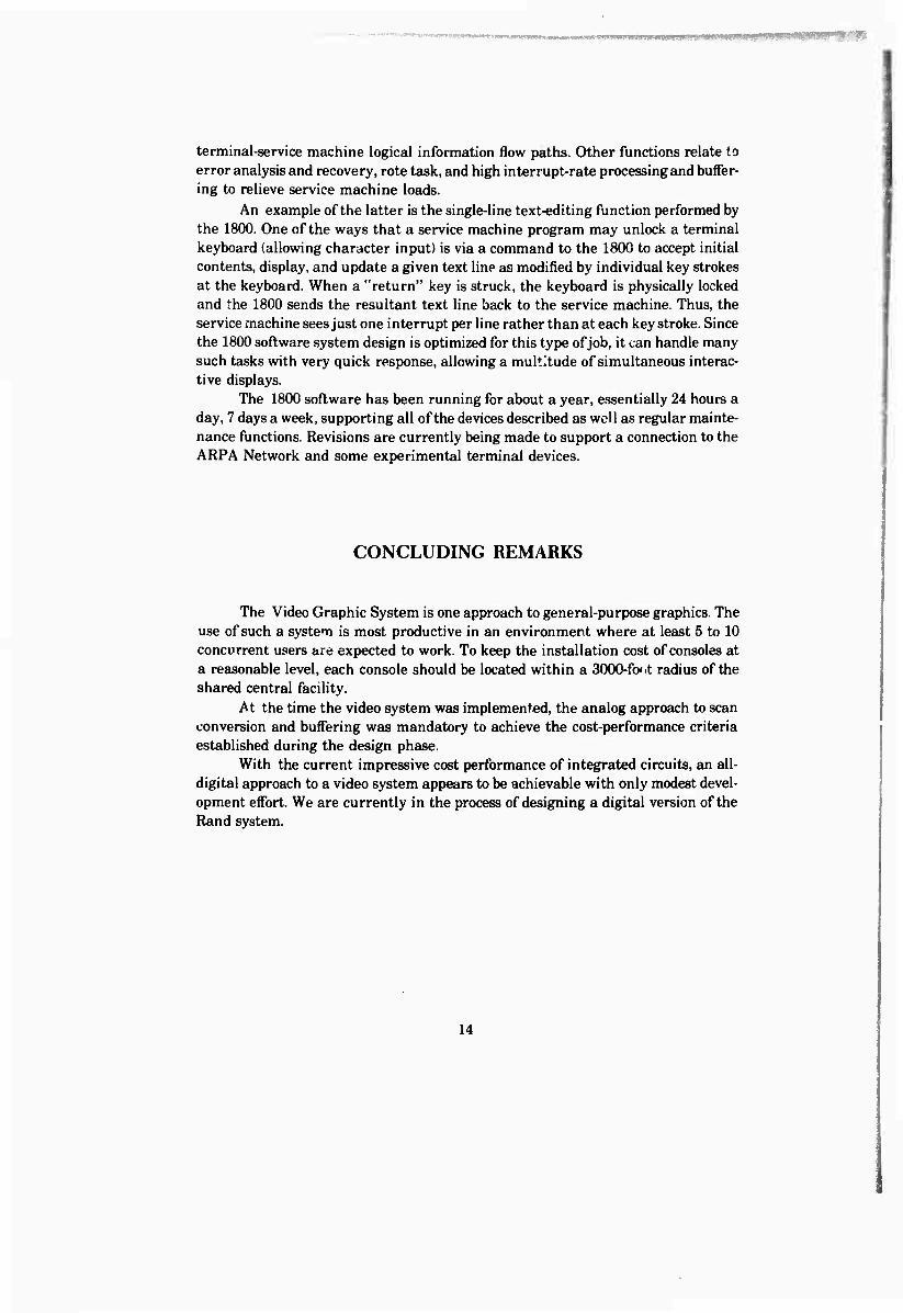
terminal-service machine logical information flow paths. Other functions relate to error analysis and recovery, rote task, and high interrupt-rate processing and buffer- ing to relieve service machine loads.
An example of the latter is the single-line text-editing function performed by the 1800. One of the ways that a service machine program may unlock a terminal keyboard (allowing character input) is via a command to the 1800 to accept initial contents, display, and update a given text line as modified by individual key strokes at the keyboard. When a "return" key is struck, the keyboard is physically locked and the 1800 sends the resultant text line back to the service machine. Thus, the service machine sees just one interrupt per line rather than at each key stroke. Since the 1800 software system design is optimized for this type of job, it can handle many such tasks with very quick response, allowing a multitude of simultaneous interac- tive displays.
The 1800 software has been running for about a year, essentially 24 hours a day, 7 days a week, supporting all of the devices described as well as regular mainte- nance functions. Revisions are currently being made to support a connection to the ARPA Network and some experimental terminal devices.
CONCLUDING REMARKS
The Video Graphic System is one approach to general-purpose graphics. The use of such a system is most productive in an environment where at least 5 to 10 concurrent users are expected to work. To keep the installation cost of consoles at a reasonable level, each console should be located within a 3000-ftx/t radius of the shared central facility.
At the time the video system was implemented, the analog approach to scan conversion and buffering was mandatory to achieve the cost-performance criteria established during the design phase.
With the current impressive cost performance of integrated circuits, an all- digital approach to a video system appears to be achievable with only modest devel- opment effort. We are currently in the process of designing a digital version of the Rand system.
14
REFERENCES
1. Rose, Gordon A., "Intergraphic: A Microprogrammed Graphical Interface Computer," IEEE Transactions on Electronic Computers, Vol. EC-16, No. 6, December 1967.
2. Engelbart, D. C., and W. K. English, "A Research Center for Augmenting Human Intellect," AFIPS 1968 FJCC Proceedings, Vol. 33, Part 1, pp. 395- 410.
3. Ball, N. A., et al., "A Shared Memory Computer Display System," IEEE Transactions on Electronic Computers, Vol. EC-lf), October 1966, pp. 750-755.
4. Macaulay, M., "Low-Cost Terminals Using Television Techniques," Na- tional Radio and Electronics Engineering Convention Abstracts, IREE (Aus- tralia), May 1967, p. 222.
5. Kennedy, J. R., "A System for Time-Sharing Graphic Consoles," 1966 Fall Joint Computer Conference, AFIPS Proceedings, Vol. 29, 1966, pp. 211-222.
6. Brown, G. D., and C. H. Bush, The Integrated Graphics System for the IBM 2250, The Rand Corporation, RM-5531-ARPA, October 1968.
7. Metzger, Richard A., "Computer Generated Graphic Segments in a Raster Display," 1969 AFIPS SJCC, Vol. 34, pp. 161-172.
8 Sutherland, W. R., J. W. Forgie, and M. V. Morellir, "Graphics in a Time Sharing: A Summary of TX-2 Experience," 1969 AFIPS SJCC, Vol. 34, pp. 629-636.
9. Gay, T. R, Jr., "A Queueing Model for Scan Conversion," 1969 AFIPS FJCC, Vol. 35, pp. 553-560.
15