Embed Size (px)
Citation preview
THE RECENTLY BUILT POLISH LARGE ARCH BRIDGES – A REVIEW OF CONSTRUCTION
TECHNOLOGY
T. SIWOWSKI1, H. ZOBEL2, TH. AL-KHAFAJI3, W.KARWOWSKI4
Arch bridges are built since two thousand years at least. Structural materials changed during this time. The design
methods were changed also. The biggest impact was noted with development of Finite Element Method and
graphical methods of preparation of technical drawings which is strictly combined with development of computers.
These processes appeared also in Polish construction industry, especially from the beginning of 90-ties XX
century.
But in this paper we do not consider mentioned above problems. We would like to present development of arch
bridges from construction technology point of view. This aspect of creation of bridge structures is not very often
the subject-matter of analysis. For many investors, design engineers and contractors optimization of structures is
most important issue. For most of them the reduction of volume (weight) of structural material is only solution.
But sometimes it is not true – the construction technology gives much more efficient results.
We present below examples of realization in Poland medium and large span arch bridges – steel, concrete and
hybrid structures.
Keywords: Bridge, Viaduct, Arch bridge, Construction technologies
1 Prof., DSc., PhD., Eng., Rzeszow University of Technology, Faculty of Civil & Environmental Engineering &
Architecture, ul. Powstancow Warszawy 12, 35-859 Rzeszow, Poland, e-mail: [email protected], ORCID: 0000-0002-2003-000X
2 Prof., DSc., PhD., Eng., Warsaw University of Technology, Faculty of Civil Engineering, Al. Armii Ludowej 16,00-637 Warsaw, Poland, e-mail: [email protected], ORCID: 0000-0002-4227-0506
3 PhD., Eng., Warsaw University of Technology, Faculty of Civil Engineering, Al. Armii Ludowej 16, 00-637 Warsaw, Poland, e-mail: [email protected], ORCID: 0000-0001-5431-2139
4 PhD., Eng., Warsaw University of Technology, Faculty of Civil Engineering, Al. Armii Ludowej 16, 00-637 Warsaw, Poland, e-mail: [email protected], ORCID: 0000-0002-8488-3407
1. INTRODUTION
There is no doubt that arch bridges are beautiful, functional, and a pleasure for the motorist to drive
over. Long-span arch bridges over deep valleys and in the cities have no competitors as far as
aesthetics is concerned Therefore they have become very popular. Arch bridges are better looking
than beam and truss bridges. Many of the contemporary arch bridges built for the last 20 – 30 years
are in the middle of cities whose residents consider these bridges not only necessary for commerce
but also their beautiful appearance [7, 16].
Arch bridges have been built for two thousand years at least. Structural materials have changed during
this time, from stone to FRP composite. The design methods have been also changed; the biggest
impact has been noted recently with the development of computers and relevant software, based
mainly on Finite Element Method (FEM) and Computer-Aided Design (CAD) codes. These processes
have appeared also in the Polish construction industry, especially after the change of economic system
at the beginning of 90-ties of XX century.
In the paper, the construction technologies of arch bridges, recently built in Poland, have been
presented. This aspect of arch bridge development is not very often the subject-matter of technical
reviews. For most of designers and contractors, the material mass reduction is the only aspect to be
considered in bridge design. However, the erection technology plays a very important role in bridge
cost optimization and can give much more efficient results. The examples supporting the above-
mentioned statement have been described in the text in the following chapters, taking into account
both concrete and steel arch bridges.
2. CLASSIFICATION AND CONCEPTUAL DESIGN OF ARCH
BRIDGES
There are many different types and arrangements of arch bridges [12]. A deck arch is one where the
bridge deck is located above the crown of the arch. The deck arch is also known as a true or perfect
arch. A through-arch is one where the bridge deck is located at the spring line of the arch. A half-
through arch is where the bridge deck is located at an elevation between a deck arch and a through
arch. A further classification refers to the articulation of the arch. A fixed arch implies no rotation
possible at the supports. A fixed arch is indeterminate to the third degree. A three-hinged arch that
allow rotation at the supports and in the crown and is statically determinate. A two-hinged arch allows
8 T. SIWOWSKI, H. ZOBEL, TH. AL-KHAFAJI, W. KARWOWSKI
rotation at the both supports and is statically indeterminate to one degree. A tied arch is one where
the reactive horizontal forces acting on the arch ribs are supplied by a tension tie at deck level of a
through or half-through arch. One proposal for arch bridges is to prestress the tie girder with
prestressing tendonts. Another is to have the deck participate with the tie girder. The tension tie is
usually a steel plate girder or a steel box girder and, depending on its stiffness, is capable of carrying
a portion of the live loads. A weak tie girder, however, requires a deep arch rib and a thin arch rib
requires a stiff deep tie girder. Since they are dependent on each other, it is possible to optimize the
size of each according to the goal established for aesthetics and/or cost.
While most through or half-through arch bridges are constructed with two planes of vertical arch ribs
there have been a few constructed with only one rib with the roadways cantilevered on each side of
the rib. Hangers usually consist of wire ropes or rolled sections. The hangers are usually vertical but
truss-like diagonal hangers have also been used. Diagonal hangers result in smaller deflections and a
reduction in the bending moments in the arch rib and deck. The inclined hangers with multiple
intersections make the network arch bridge act like a truss, with only axial compressible and tensile
forces. Bending moments and shear forces are very small in network arches. The hanger arrangement
is what separates network tied arch structures from other types of tied arches, such as those with
vertical hangers. It is defined by the number of hangers, hanger inclination and hanger distance. There
have also been arch bridges constructed with the arch ribs tilted so they can be connected at the crown.
This is done for aesthetic reasons but it does add to the lateral stiffness of the arch bridge and could
result in reduced bracing requirements.
By deck is meant the roadway concrete slab or orthotropic steel plate and its structural supports. The
rise-to-span ratio for arches may vary widely because an arch can be very shallow or, at the other
extreme, could be a half-circle. Most arches would have rise-to-span ratios within the range of 1:4.5
to 1:6. Steel arch ribs are usually made up of plates in the shape of a rectangular box. The ties are
usually either welded steel box girders or plate girders. After the moments and axial forces become
available from the three-dimensional finite-element nonlinear analysis the arch elements, such as the
deck, ribs, ties, hangers, and columns can be proportioned. Table 1 contains information suitable for
conceptual design. It shows relation between structural material and form with position of the deck,
slenderness and length of span.
THE RECENTLY BUILT POLISH LARGE ARCH BRIDGES – A REVIEW OF CONSTRUCTION... 9
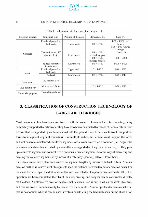
Table 1. Preliminary data for conceptual design [16]
Structural material Structural form Position of the deck Slenderness f/L Ratio h/L
Concrete
Fixed and pinned at both ends Upper deck 1/3 ÷ 1/7 L
1/60 ÷ 1/100 road bridge
1/30 ÷ 1/50 railway bridge
Tied arch more stiff than the deck Lower deck
1/4 ÷ 1/5 Lvertical hangers
1/4 ÷ 1/6 Linclined hangers
1/30 ÷ 150
1/80 ÷ 1/100
The deck more stiff than the arch
Lower deck 1/6 ÷ 1/7 L 1/100 ÷ 1/120
Steel
Fixed and pinned at both ends
Upper deck 1/7 ÷ 1/10 L 1/40 ÷ 1/60
Tied arch Lower deck 1/6 ÷ 1/9 L 1/25 ÷ 1/40
Aluminium The same as steel
Glue-lam timberAll structural forms 1/7 ÷ 1/10 L 1/30 ÷ 1/50
Composite polymerTo small population
3. CLASSIFICATION OF CONSTRUCTION TECHNOLOGY OF
LARGE ARCH BRIDGES
Most concrete arches have been constructed with the concrete forms and in situ concreting being
completely supported by falsework. They have also been constructed by means of tieback cables from
a tower that is supported by cables anchored into the ground. Each tieback cable would support the
forms for a segment length of concrete rib. For multiple arches, the tiebacks would support the forms
and wet concrete in balanced cantilever segments off a tower erected on a common pier. Segmental
concrete arches have been erected by cranes that are supported on the ground or on barges. They pick
up a concrete segment and connect it to a previously erected segment. Another way of delivering and
erecting the concrete segments is by means of a cableway spanning between tower bents.
Steel deck arches have also been erected in segment lengths by means of tieback cables. Another
erection method is to have steel rib segments span the distance between temporary erection bents. For
the usual tied-arch span the deck and steel tie can be erected on temporary erection bents. When this
operation has been completed, the ribs of the arch, bracing, and hangers can be constructed directly
off the deck. An alternative erection scheme that has been used is one in which the deck, steel ties,
and ribs are erected simultaneously by means of tieback cables. A more spectacular erection scheme,
that is economical when it can be used, involves constructing the tied-arch span on the shore or on
10 T. SIWOWSKI, H. ZOBEL, TH. AL-KHAFAJI, W. KARWOWSKI
piles adjacent and parallel to the shore. When completed the tied arch is floated on barges to the
bridge site and then pulled up vertically to its final position in the bridge. Some arches have had a rib
erected on each shoreline in the vertical position as a column. When completed, the ribs are then
rotated down to meet at the center between the shorelines.
Summing up, the construction methods of arch bridges can be as follows:
� cast-in-situ (reinforced concrete and post-tensioned structures),
� assembling on the scaffold (steel and precast concrete structure) on site,
� lifting of whole structure and placement on piers with/without temporary supports after assembling
in factory or in construction site,
� launching with/without temporary supports along or across to longitudinal axis of the bridge,
� cantilever method with/without temporary pylons and cables,
� floating and lifting.
4. CAST-IN-SITU AND PRECAST ASSEMBLING OF THE
CONCRETE ARCH BRIDGES WITH/WITHOUT TEMPORARY
SUPPORTS
4.1. INTRODUCTION
Technologies used for erection of a concrete arch bridges can be divided generally in two main
groups: cast-in-situ construction and precast construction (prefabrication). In basic terms, cast-in-situ
construction describes a process whereby segments (or entire spans) are progressively cast on site in
their final positions within the structure. By comparison, for precast construction, the segments are
prefabricated at a casting plant – either on site or at a remote facility – then transported to the project
site and erected as completed units in their final positions. Safety, serviceability, cost-effectiveness,
aesthetics and particular technical issues are typically the controlling factors in the selection of the
proper concrete bridge construction method [9]. There are not many concrete arch bridges built in
Poland in recent 30 years. However two examples to illustrate the recent domestic achievement in
both technologies have been chosen and presented below.
4. 2. THE CASTLE BRIDGE IN RZESZOW [8,14]
THE RECENTLY BUILT POLISH LARGE ARCH BRIDGES – A REVIEW OF CONSTRUCTION... 11
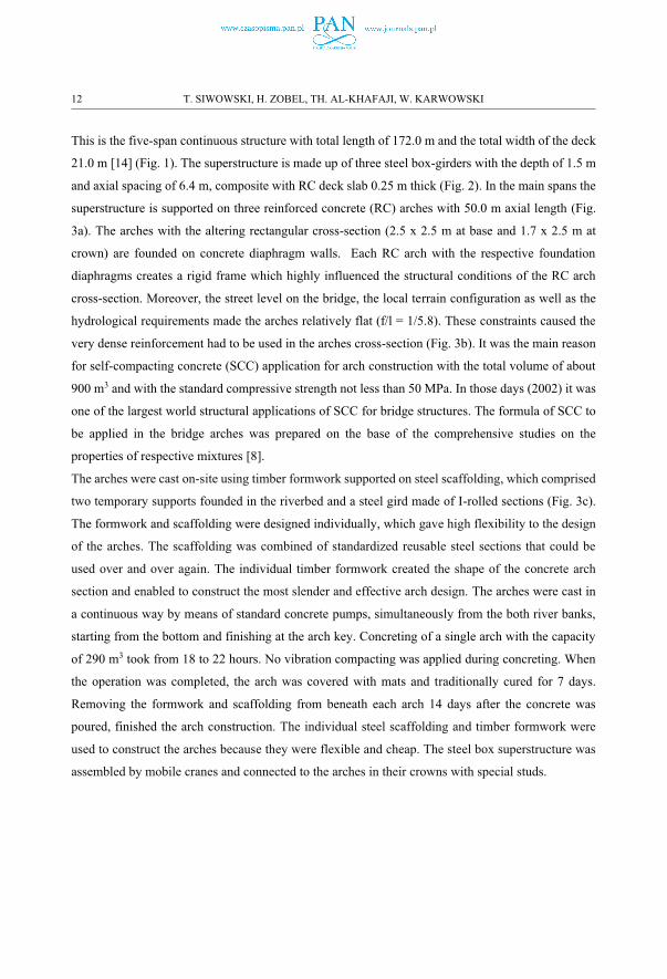
This is the five-span continuous structure with total length of 172.0 m and the total width of the deck
21.0 m [14] (Fig. 1). The superstructure is made up of three steel box-girders with the depth of 1.5 m
and axial spacing of 6.4 m, composite with RC deck slab 0.25 m thick (Fig. 2). In the main spans the
superstructure is supported on three reinforced concrete (RC) arches with 50.0 m axial length (Fig.
3a). The arches with the altering rectangular cross-section (2.5 x 2.5 m at base and 1.7 x 2.5 m at
crown) are founded on concrete diaphragm walls. Each RC arch with the respective foundation
diaphragms creates a rigid frame which highly influenced the structural conditions of the RC arch
cross-section. Moreover, the street level on the bridge, the local terrain configuration as well as the
hydrological requirements made the arches relatively flat (f/l = 1/5.8). These constraints caused the
very dense reinforcement had to be used in the arches cross-section (Fig. 3b). It was the main reason
for self-compacting concrete (SCC) application for arch construction with the total volume of about
900 m3 and with the standard compressive strength not less than 50 MPa. In those days (2002) it was
one of the largest world structural applications of SCC for bridge structures. The formula of SCC to
be applied in the bridge arches was prepared on the base of the comprehensive studies on the
properties of respective mixtures [8].
The arches were cast on-site using timber formwork supported on steel scaffolding, which comprised
two temporary supports founded in the riverbed and a steel gird made of I-rolled sections (Fig. 3c).
The formwork and scaffolding were designed individually, which gave high flexibility to the design
of the arches. The scaffolding was combined of standardized reusable steel sections that could be
used over and over again. The individual timber formwork created the shape of the concrete arch
section and enabled to construct the most slender and effective arch design. The arches were cast in
a continuous way by means of standard concrete pumps, simultaneously from the both river banks,
starting from the bottom and finishing at the arch key. Concreting of a single arch with the capacity
of 290 m3 took from 18 to 22 hours. No vibration compacting was applied during concreting. When
the operation was completed, the arch was covered with mats and traditionally cured for 7 days.
Removing the formwork and scaffolding from beneath each arch 14 days after the concrete was
poured, finished the arch construction. The individual steel scaffolding and timber formwork were
used to construct the arches because they were flexible and cheap. The steel box superstructure was
assembled by mobile cranes and connected to the arches in their crowns with special studs.
12 T. SIWOWSKI, H. ZOBEL, TH. AL-KHAFAJI, W. KARWOWSKI
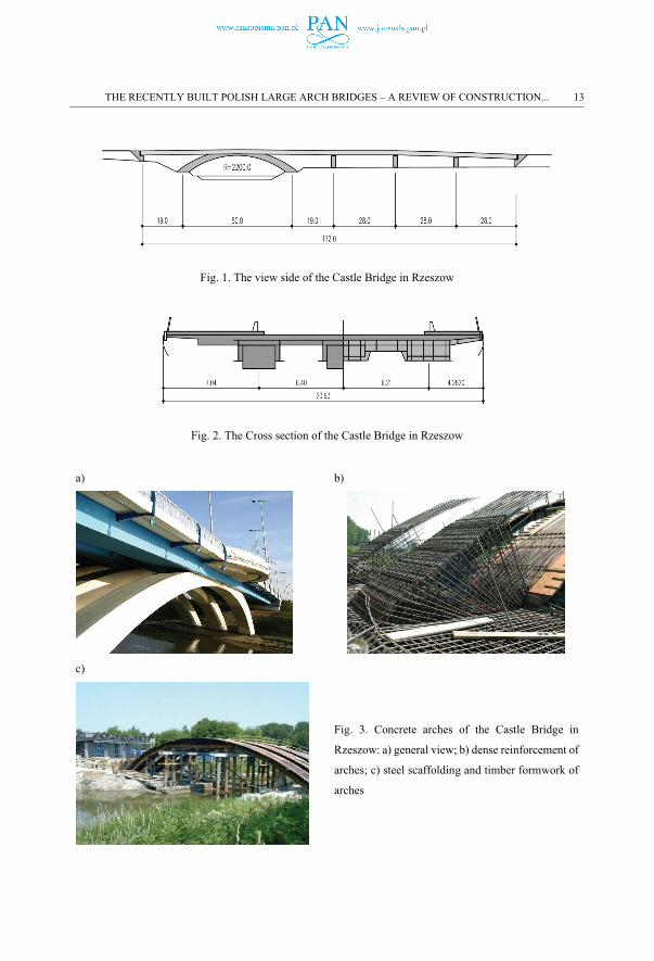
Fig. 1. The view side of the Castle Bridge in Rzeszow
Fig. 2. The Cross section of the Castle Bridge in Rzeszow
a) b)
c)
Fig. 3. Concrete arches of the Castle Bridge in
Rzeszow: a) general view; b) dense reinforcement of
arches; c) steel scaffolding and timber formwork of
arches
THE RECENTLY BUILT POLISH LARGE ARCH BRIDGES – A REVIEW OF CONSTRUCTION... 13
b
4.3. VIADUCT IN MILOWKA ALONG S69 EXPRESSWAY [5]
In precast arch bridge construction, the individual components (arch segments) are manufactured off-
site and assembled on-site. This method usually increases the arch durability, reduces on-site work
and construction time, minimises environmental burdens and traffic disruption, and lowers life-cycle
costs. Pre-casting gives the benefit of good control of the quality of construction, while the deck
construction is simple and repetitive. Bridge superstructures made of precast arches are widely used
nowadays. The only Polish example of a large arch bridge made of precast segments is the bridge in
Milowka, located along the S69 expressway connecting the city of Bielsko - Biala and Silesia region
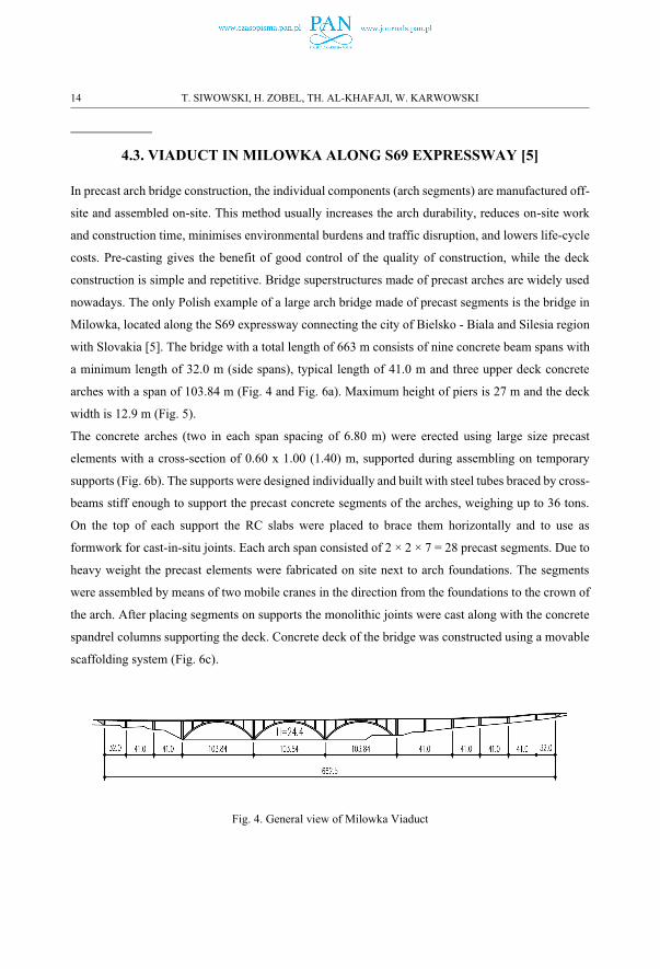
with Slovakia [5]. The bridge with a total length of 663 m consists of nine concrete beam spans with
a minimum length of 32.0 m (side spans), typical length of 41.0 m and three upper deck concrete
arches with a span of 103.84 m (Fig. 4 and Fig. 6a). Maximum height of piers is 27 m and the deck
width is 12.9 m (Fig. 5).
The concrete arches (two in each span spacing of 6.80 m) were erected using large size precast
elements with a cross-section of 0.60 x 1.00 (1.40) m, supported during assembling on temporary
supports (Fig. 6b). The supports were designed individually and built with steel tubes braced by cross-
beams stiff enough to support the precast concrete segments of the arches, weighing up to 36 tons.
On the top of each support the RC slabs were placed to brace them horizontally and to use as
formwork for cast-in-situ joints. Each arch span consisted of 2 × 2 × 7 = 28 precast segments. Due to
heavy weight the precast elements were fabricated on site next to arch foundations. The segments
were assembled by means of two mobile cranes in the direction from the foundations to the crown of
the arch. After placing segments on supports the monolithic joints were cast along with the concrete
spandrel columns supporting the deck. Concrete deck of the bridge was constructed using a movable
scaffolding system (Fig. 6c).
Fig. 4. General view of Milowka Viaduct
14 T. SIWOWSKI, H. ZOBEL, TH. AL-KHAFAJI, W. KARWOWSKI
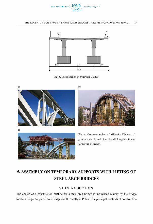
Fig. 5. Cross section of Milowka Viaduct
a) b)
c)
Fig. 6. Concrete arches of Milowka Viaduct a)
general view; b) and c) steel scaffolding and timber
formwork of arches
5. ASSEMBLY ON TEMPORARY SUPPORTS WITH LIFTING OF
STEEL ARCH BRIDGES
5.1. INTRODUCTIONThe choice of a construction method for a steel arch bridge is influenced mainly by the bridge
location. Regarding steel arch bridges built recently in Poland, the principal methods of construction
THE RECENTLY BUILT POLISH LARGE ARCH BRIDGES – A REVIEW OF CONSTRUCTION... 15
are: construction with a mobile crane from the ground and/or the deck, placement of large steel
segments with heavy lifting methods, construction by launching, and floating segment or an entire
superstructure with a barge.
Construction with a mobile crane is an advantageous means of erecting the steel arch because it
requires less equipment on site and a reduced amount of labour. Erection using cranes is considered
the most cost effective erection method for the majority of steel structures. However, it does require
good accessibility around the construction site. The erection may take place either with or without
temporary supports. Due to the increasing capacity of lifting equipment, the current trend is to avoid
the falsework which is generally expensive, while increasing the size of the steelwork pieces and
making the maximum use of those parts of the superstructure already in place to support those that
follow. The bending moments that can be resisted at the bases of the telescopic arms of mobile cranes
currently used worldwide can be as high as 15,000 kNm, which means that, e.g. a weight of 100 tones
can be carried at a distance of 15 m. If the arch spans are sufficiently short, and the size of the
individual steelwork pieces allows, the temporary supports can be avoided.
However, if temporary supports are used, they may be either continuous or discrete. The evolution of
heavy lifting equipment means that when temporary supports are needed, they tend to be a small
number of discrete props rather than continuous falsework. An alternative method may be used if the
deck of the bridge is sufficiently strong and stiff in bending, or perhaps it can be supported with
temporary supports. To begin with, the deck is constructed either from the ground or launched. Once
the deck is in place, it serves as a working platform for constructing the arches. Falsework towers are
supported on the deck and allow relatively easy erection of the arches.
5.2. STEEL ARCH BRIDGE MA-37 ALONG A4 MOTORWAY OVER SAN
RIVER [2]
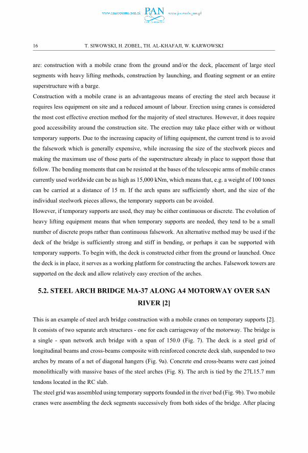
This is an example of steel arch bridge construction with a mobile cranes on temporary supports [2].
It consists of two separate arch structures - one for each carriageway of the motorway. The bridge is
a single - span network arch bridge with a span of 150.0 (Fig. 7). The deck is a steel grid of
longitudinal beams and cross-beams composite with reinforced concrete deck slab, suspended to two
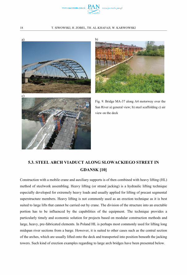
arches by means of a net of diagonal hangers (Fig. 9a). Concrete end cross-beams were cast joined
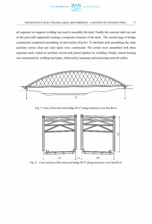
monolithically with massive bases of the steel arches (Fig. 8). The arch is tied by the 27L15.7 mm
tendons located in the RC slab.
The steel grid was assembled using temporary supports founded in the river bed (Fig. 9b). Two mobile
cranes were assembling the deck segments successively from both sides of the bridge. After placing
16 T. SIWOWSKI, H. ZOBEL, TH. AL-KHAFAJI, W. KARWOWSKI
all segments on supports welding was used to assembly the deck. Finally the concrete slab was cast
on the grid (still supported) creating a composite structure of the deck. The second stage of bridge
construction comprised assembling of steel arches (Fig.9c). To facilitate arch assembling the outer
auxiliary towers (four per each span) were constructed. The arches were assembled with three
segments each, rested on auxiliary towers and joined together by wielding. Finally, lateral bracing
was constructed by welding steel pipes, followed by mounting and tensioning network cables.
Fig. 7. View of the steel arch bridge M-37 along motorway over San River
Fig. 8. . Cross section of the steel arch bridge M-37 along motorway over San River
THE RECENTLY BUILT POLISH LARGE ARCH BRIDGES – A REVIEW OF CONSTRUCTION... 17
a) b)
c)
Fig. 9. Bridge MA-37 along A4 motorway over the
San River a) general view; b) steel scaffolding c) air
view on the deck
5.3. STEEL ARCH VIADUCT ALONG SLOWACKIEGO STREET IN
GDANSK [10]
Construction with a mobile crane and auxiliary supports is of then combined with heavy lifting (HL)
method of steelwork assembling. Heavy lifting (or strand jacking) is a hydraulic lifting technique
especially developed for extremely heavy loads and usually applied for lifting of precast segmental
superstructure members. Heavy lifting is not commonly used as an erection technique as it is best
suited to large lifts that cannot be carried out by crane. The division of the structure into an erectable
portion has to be influenced by the capabilities of the equipment. The technique provides a
particularly timely and economic solution for projects based on modular construction methods and
large, heavy, pre-fabricated elements. In Poland HL is perhaps most commonly used for lifting long
midspan river sections from a barge. However, it is suited to other cases such as the central section
of the arches, which are usually lifted onto the deck and transported into position beneath the jacking
towers. Such kind of erection examples regarding to large arch bridges have been presented below.
18 T. SIWOWSKI, H. ZOBEL, TH. AL-KHAFAJI, W. KARWOWSKI
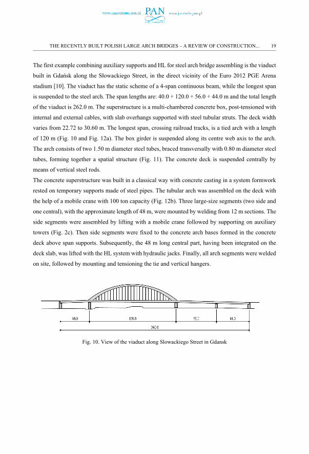
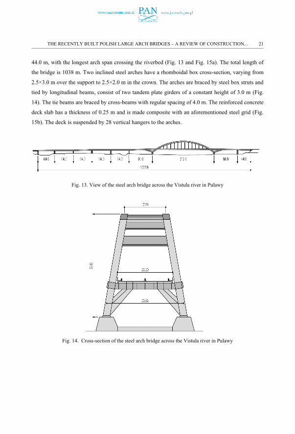
The first example combining auxiliary supports and HL for steel arch bridge assembling is the viaduct
built in Gdańsk along the Słowackiego Street, in the direct vicinity of the Euro 2012 PGE Arena
stadium [10]. The viaduct has the static scheme of a 4-span continuous beam, while the longest span
is suspended to the steel arch. The span lengths are: 40.0 + 120.0 + 56.0 + 44.0 m and the total length
of the viaduct is 262.0 m. The superstructure is a multi-chambered concrete box, post-tensioned with
internal and external cables, with slab overhangs supported with steel tubular struts. The deck width
varies from 22.72 to 30.60 m. The longest span, crossing railroad tracks, is a tied arch with a length
of 120 m (Fig. 10 and Fig. 12a). The box girder is suspended along its centre web axis to the arch.
The arch consists of two 1.50 m diameter steel tubes, braced transversally with 0.80 m diameter steel
tubes, forming together a spatial structure (Fig. 11). The concrete deck is suspended centrally by
means of vertical steel rods.
The concrete superstructure was built in a classical way with concrete casting in a system formwork
rested on temporary supports made of steel pipes. The tubular arch was assembled on the deck with
the help of a mobile crane with 100 ton capacity (Fig. 12b). Three large-size segments (two side and
one central), with the approximate length of 48 m, were mounted by welding from 12 m sections. The
side segments were assembled by lifting with a mobile crane followed by supporting on auxiliary
towers (Fig. 2c). Then side segments were fixed to the concrete arch bases formed in the concrete
deck above span supports. Subsequently, the 48 m long central part, having been integrated on the
deck slab, was lifted with the HL system with hydraulic jacks. Finally, all arch segments were welded
on site, followed by mounting and tensioning the tie and vertical hangers.
Fig. 10. View of the viaduct along Slowackiego Street in Gdansk
THE RECENTLY BUILT POLISH LARGE ARCH BRIDGES – A REVIEW OF CONSTRUCTION... 19
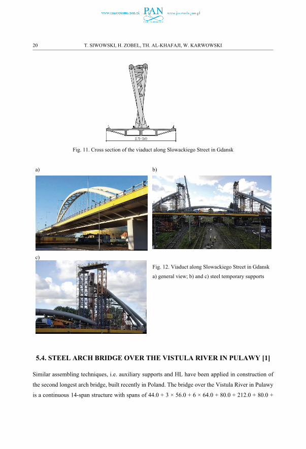
Fig. 11. Cross section of the viaduct along Slowackiego Street in Gdansk
a) b)
c)
Fig. 12. Viaduct along Slowackiego Street in Gdansk
a) general view; b) and c) steel temporary supports
5.4. STEEL ARCH BRIDGE OVER THE VISTULA RIVER IN PULAWY [1]
Similar assembling techniques, i.e. auxiliary supports and HL have been applied in construction of
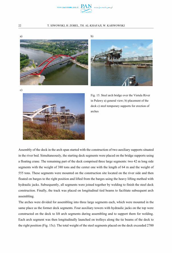
the second longest arch bridge, built recently in Poland. The bridge over the Vistula River in Pulawy
is a continuous 14-span structure with spans of 44.0 + 3 × 56.0 + 6 × 64.0 + 80.0 + 212.0 + 80.0 +
20 T. SIWOWSKI, H. ZOBEL, TH. AL-KHAFAJI, W. KARWOWSKI
44.0 m, with the longest arch span crossing the riverbed (Fig. 13 and Fig. 15a). The total length of
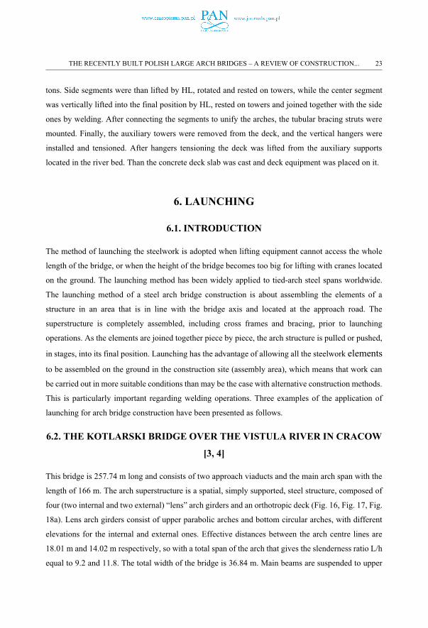
the bridge is 1038 m. Two inclined steel arches have a rhomboidal box cross-section, varying from
2.5×3.0 m over the support to 2.5×2.0 m in the crown. The arches are braced by steel box struts and
tied by longitudinal beams, consist of two tandem plate girders of a constant height of 3.0 m (Fig.
14). The tie beams are braced by cross-beams with regular spacing of 4.0 m. The reinforced concrete
deck slab has a thickness of 0.25 m and is made composite with an aforementioned steel grid (Fig.
15b). The deck is suspended by 28 vertical hangers to the arches.
Fig. 13. View of the steel arch bridge across the Vistula river in Pulawy
Fig. 14. Cross-section of the steel arch bridge across the Vistula river in Pulawy
THE RECENTLY BUILT POLISH LARGE ARCH BRIDGES – A REVIEW OF CONSTRUCTION... 21
a) b)
c)
Fig. 15. Steel arch bridge over the Vistula River
in Pulawy a) general view; b) placement of the
deck c) steel temporary supports for erection of
arches
Assembly of the deck in the arch span started with the construction of two auxiliary supports situated
in the river bed. Simultaneously, the starting deck segments were placed on the bridge supports using
a floating crane. The remaining part of the deck comprised three large segments: two 42 m long side
segments with the weight of 380 tons and the center one with the length of 64 m and the weight of
555 tons. These segments were mounted on the construction site located on the river side and then
floated on barges to the right position and lifted from the barges using the heavy lifting method with
hydraulic jacks. Subsequently, all segments were joined together by welding to finish the steel deck
construction. Finally, the track was placed on longitudinal tied beams to facilitate subsequent arch
assembling.
The arches were divided for assembling into three large segments each, which were mounted in the
same place as the former deck segments. Four auxiliary towers with hydraulic jacks on the top were
constructed on the deck to lift arch segments during assembling and to support them for welding.
Each arch segment was then longitudinally launched on trolleys along the tie beams of the deck to
the right position (Fig. 15c). The total weight of the steel segments placed on the deck exceeded 2700
22 T. SIWOWSKI, H. ZOBEL, TH. AL-KHAFAJI, W. KARWOWSKI
tons. Side segments were than lifted by HL, rotated and rested on towers, while the center segment
was vertically lifted into the final position by HL, rested on towers and joined together with the side
ones by welding. After connecting the segments to unify the arches, the tubular bracing struts were
mounted. Finally, the auxiliary towers were removed from the deck, and the vertical hangers were
installed and tensioned. After hangers tensioning the deck was lifted from the auxiliary supports
located in the river bed. Than the concrete deck slab was cast and deck equipment was placed on it.
6. LAUNCHING
6.1. INTRODUCTION
The method of launching the steelwork is adopted when lifting equipment cannot access the whole
length of the bridge, or when the height of the bridge becomes too big for lifting with cranes located
on the ground. The launching method has been widely applied to tied-arch steel spans worldwide.
The launching method of a steel arch bridge construction is about assembling the elements of a
structure in an area that is in line with the bridge axis and located at the approach road. The
superstructure is completely assembled, including cross frames and bracing, prior to launching
operations. As the elements are joined together piece by piece, the arch structure is pulled or pushed,
in stages, into its final position. Launching has the advantage of allowing all the steelwork elements
to be assembled on the ground in the construction site (assembly area), which means that work can
be carried out in more suitable conditions than may be the case with alternative construction methods.
This is particularly important regarding welding operations. Three examples of the application of
launching for arch bridge construction have been presented as follows.
6.2. THE KOTLARSKI BRIDGE OVER THE VISTULA RIVER IN CRACOW
[3, 4]
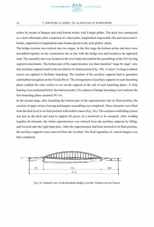
This bridge is 257.74 m long and consists of two approach viaducts and the main arch span with the
length of 166 m. The arch superstructure is a spatial, simply supported, steel structure, composed of
four (two internal and two external) “lens” arch girders and an orthotropic deck (Fig. 16, Fig. 17, Fig.
18a). Lens arch girders consist of upper parabolic arches and bottom circular arches, with different
elevations for the internal and external ones. Effective distances between the arch centre lines are
18.01 m and 14.02 m respectively, so with a total span of the arch that gives the slenderness ratio L/h
equal to 9.2 and 11.8. The total width of the bridge is 36.84 m. Main beams are suspended to upper
THE RECENTLY BUILT POLISH LARGE ARCH BRIDGES – A REVIEW OF CONSTRUCTION... 23
arches by means of hangers and with bottom arches with I-shape pillars. The deck was constructed
as a steel orthotropic plate composed of a sheet plate, longitudinal trapezoidal ribs and transversal I-
beams, supported on longitudinal main beams placed at the arch girders’ plane.
The bridge erection was realized into two stages. In the first stage the bottom arches and deck were
assembled together on the construction site in line with the bridge axis and located at the approach
road. The assembly area was located on the river bank and enabled the assembling of the 50.5 m long
segment (maximum). The bottom part of the superstructure was than launched “stage by stage” onto
four auxiliary supports built in the reverbed to its final position (Fig. 18b). A short 5 m long avanback
(nose) was applied to facilitate launching. The location of the auxiliary supports had to guarantee
undisturbed navigation on the Vistula River. The arrangement of auxiliary supports in each launching
phase enabled the outer arches to rest on the supports at the end of each launching phase. A slide
bearing were positioned below the internal arches. Five phases of bridge launching were realized, the
first launching phase assumed 50.5 m.
In the second stage, after launching the bottom part of the superstructure into its final position, the
erection of upper arches, bracing and hangers assembling was completed. These elements were lifted
from the deck level to its final position with mobile cranes (Fig. 18c). The common scaffolding system
was put on the deck and used to support all pieces of a steelwork to be mounted. After welding
together all elements, the whole superstructure was released from the auxiliary supports by lifting,
and lowered onto the right bank piers. After the superstructure had been lowered to its final position,
the auxiliary supports were removed from the riverbed. The final regulation of vertical hangers was
then completed.
Fig. 16. General view of the Kotlarski bridge over the Vistula river in Cracow
24 T. SIWOWSKI, H. ZOBEL, TH. AL-KHAFAJI, W. KARWOWSKI

Fig. 17. Cross section of the Kotlarski bridge over the Vistula river in Cracow
a) b)
c)
Fig. 18. Kotlarski steel arch bridge over the
Vistula River in Cracow a) general view; b)
construction of the deck c) erection of arches on
steel temporary supports placed on the deck
THE RECENTLY BUILT POLISH LARGE ARCH BRIDGES – A REVIEW OF CONSTRUCTION... 25
6.3. BRIDGE OVER THE WARTA RIVER ALONG THE S3 EXPRESSWAY
[11]
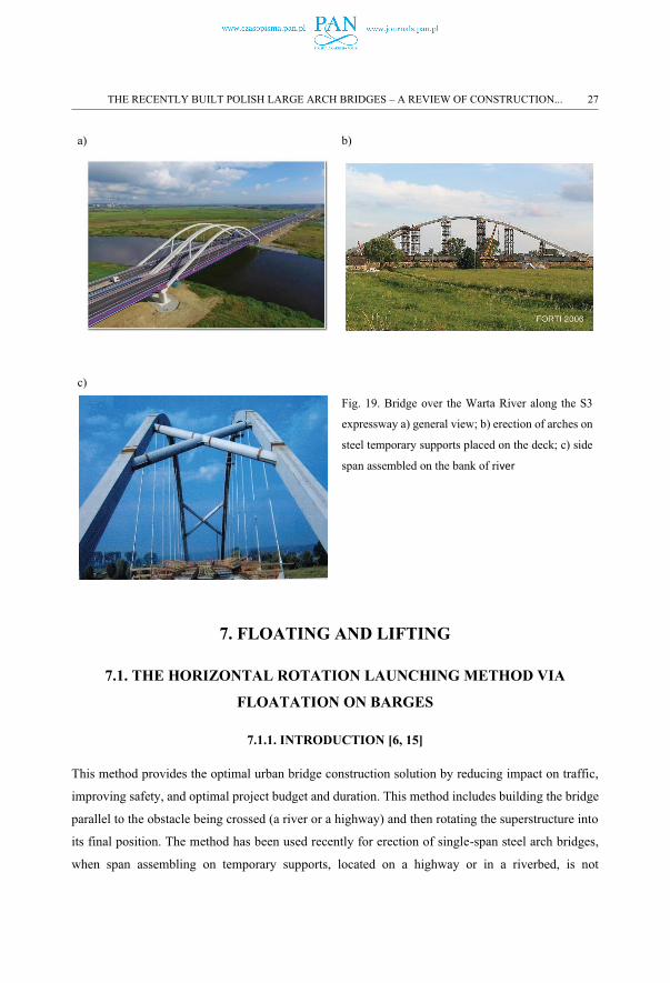
The launching method has been also used as the construction method of the mentioned above bridge.
It consists of two separate structures - one for each carriageway of the expressway. The each bridge
consists of two parts, separated by an expansion joint: section I – the midstream part and section II –
the approaching part over flooding area. The midstream section is a continuous, six-span composite
structure, with a total length of 396.0 m (48.0+60.0+60.0+120.0+60.0+48.0). The longest span of two
steel tied arches is 120.0 m. The total width of the superstructure structure is 14.40 m (Fig. 19a). The
entire deck consists of two steel box girders made composite with the RC deck slab. The slender steel
arches have a parabolic shape in the centre section (near the crown) and straight sections near the
bases. Both steel arches with the box-section of 1.45 x 1.2 m are braced transversally by two „X”
shaped steel tube bracing at portal parts of the structure and the RC cross-beams at the supports (Fig.
19c). In the arch span the deck is suspended to the arches by means of steel rods. The hangers are
anchored in the parabolic section of the arches and have a fan arrangement radiating towards the deck.
The entire arch span along with the respective approaching spans was assembled on the embankment
in the riverside. Starting with the deck the subsequent steel elements of both arches with a length of
approximately 30 m were successively positioned, mounted and welded together. After assembling
of the arch span and two approaching spans at both sides of the arch, the launching begun.
Construction technology assumed launching the whole steel structure of the bridge using an auxiliary
support located in the riverbed (Fig. 19b). Moreover, an avanback (nose) was applied to facilitate
launching. After the launching has been completed, the cable hangers were installed and adjusted by
means of hydraulic jacks located on the auxiliary support in the mid-span, which allowed for lifting
or lowering the deck. After installation and pre-tension of the hangers, the auxiliary support was
removed. In the last construction stage the RC slab was cast on the entire steelwork followed by the
installation of deck equipment and final hangers’ adjusting
26 T. SIWOWSKI, H. ZOBEL, TH. AL-KHAFAJI, W. KARWOWSKI
a) b)
c)
Fig. 19. Bridge over the Warta River along the S3
expressway a) general view; b) erection of arches on
steel temporary supports placed on the deck; c) side
span assembled on the bank of river
7. FLOATING AND LIFTING
7.1. THE HORIZONTAL ROTATION LAUNCHING METHOD VIA
FLOATATION ON BARGES
7.1.1. INTRODUCTION [6, 15]
This method provides the optimal urban bridge construction solution by reducing impact on traffic,
improving safety, and optimal project budget and duration. This method includes building the bridge
parallel to the obstacle being crossed (a river or a highway) and then rotating the superstructure into
its final position. The method has been used recently for erection of single-span steel arch bridges,
when span assembling on temporary supports, located on a highway or in a riverbed, is not
THE RECENTLY BUILT POLISH LARGE ARCH BRIDGES – A REVIEW OF CONSTRUCTION... 27
practicable. The superstructure is assembled on scaffolding situated on one bank (or alongside the
highway) and launched by rotation pivoting about the one of superstructure's bearings into the
bridge’s final position. During this rotation process, one of the superstructure’s ends rests on a special
bearing, positioned directly on a bridge abutment (or on a fixed temporary support), and the second
is rested on a movable support, such as a roller for land or on a barge for water. The rotation launching
method has been used successfully in the last decade in over one hundred bridges in Austria, Canada,
China, Germany, France, Italy, Japan, and the Republic of Slovakia and includes arch bridges [6, 15].
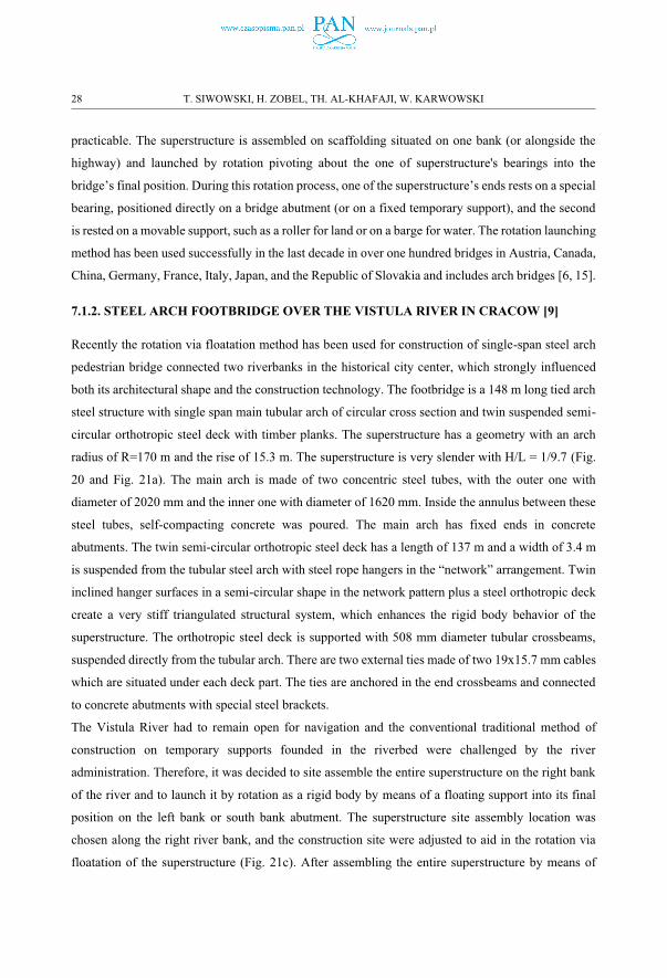
7.1.2. STEEL ARCH FOOTBRIDGE OVER THE VISTULA RIVER IN CRACOW [9]
Recently the rotation via floatation method has been used for construction of single-span steel arch
pedestrian bridge connected two riverbanks in the historical city center, which strongly influenced
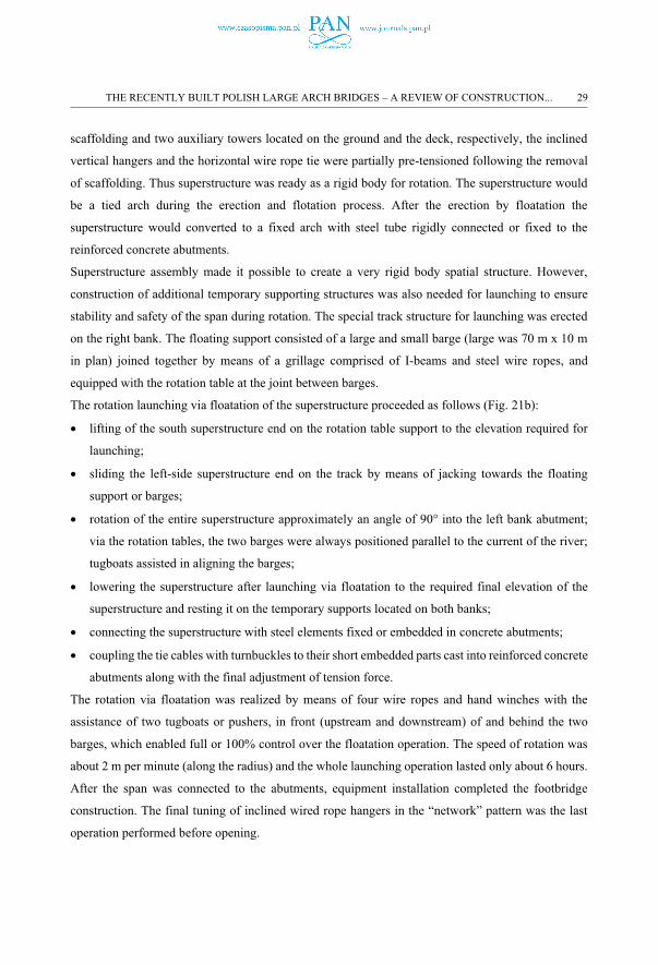
both its architectural shape and the construction technology. The footbridge is a 148 m long tied arch
steel structure with single span main tubular arch of circular cross section and twin suspended semi-
circular orthotropic steel deck with timber planks. The superstructure has a geometry with an arch
radius of R=170 m and the rise of 15.3 m. The superstructure is very slender with H/L = 1/9.7 (Fig.
20 and Fig. 21a). The main arch is made of two concentric steel tubes, with the outer one with
diameter of 2020 mm and the inner one with diameter of 1620 mm. Inside the annulus between these
steel tubes, self-compacting concrete was poured. The main arch has fixed ends in concrete
abutments. The twin semi-circular orthotropic steel deck has a length of 137 m and a width of 3.4 m
is suspended from the tubular steel arch with steel rope hangers in the “network” arrangement. Twin
inclined hanger surfaces in a semi-circular shape in the network pattern plus a steel orthotropic deck
create a very stiff triangulated structural system, which enhances the rigid body behavior of the
superstructure. The orthotropic steel deck is supported with 508 mm diameter tubular crossbeams,
suspended directly from the tubular arch. There are two external ties made of two 19x15.7 mm cables
which are situated under each deck part. The ties are anchored in the end crossbeams and connected
to concrete abutments with special steel brackets.
The Vistula River had to remain open for navigation and the conventional traditional method of
construction on temporary supports founded in the riverbed were challenged by the river
administration. Therefore, it was decided to site assemble the entire superstructure on the right bank
of the river and to launch it by rotation as a rigid body by means of a floating support into its final
position on the left bank or south bank abutment. The superstructure site assembly location was
chosen along the right river bank, and the construction site were adjusted to aid in the rotation via
floatation of the superstructure (Fig. 21c). After assembling the entire superstructure by means of
28 T. SIWOWSKI, H. ZOBEL, TH. AL-KHAFAJI, W. KARWOWSKI
scaffolding and two auxiliary towers located on the ground and the deck, respectively, the inclined
vertical hangers and the horizontal wire rope tie were partially pre-tensioned following the removal
of scaffolding. Thus superstructure was ready as a rigid body for rotation. The superstructure would
be a tied arch during the erection and flotation process. After the erection by floatation the
superstructure would converted to a fixed arch with steel tube rigidly connected or fixed to the
reinforced concrete abutments.
Superstructure assembly made it possible to create a very rigid body spatial structure. However,
construction of additional temporary supporting structures was also needed for launching to ensure
stability and safety of the span during rotation. The special track structure for launching was erected
on the right bank. The floating support consisted of a large and small barge (large was 70 m x 10 m
in plan) joined together by means of a grillage comprised of I-beams and steel wire ropes, and
equipped with the rotation table at the joint between barges.
The rotation launching via floatation of the superstructure proceeded as follows (Fig. 21b):
� lifting of the south superstructure end on the rotation table support to the elevation required for
launching;
� sliding the left-side superstructure end on the track by means of jacking towards the floating
support or barges;
� rotation of the entire superstructure approximately an angle of 90° into the left bank abutment;
via the rotation tables, the two barges were always positioned parallel to the current of the river;
tugboats assisted in aligning the barges;
� lowering the superstructure after launching via floatation to the required final elevation of the
superstructure and resting it on the temporary supports located on both banks;
� connecting the superstructure with steel elements fixed or embedded in concrete abutments;
� coupling the tie cables with turnbuckles to their short embedded parts cast into reinforced concrete
abutments along with the final adjustment of tension force.
The rotation via floatation was realized by means of four wire ropes and hand winches with the
assistance of two tugboats or pushers, in front (upstream and downstream) of and behind the two
barges, which enabled full or 100% control over the floatation operation. The speed of rotation was
about 2 m per minute (along the radius) and the whole launching operation lasted only about 6 hours.
After the span was connected to the abutments, equipment installation completed the footbridge
construction. The final tuning of inclined wired rope hangers in the “network” pattern was the last
operation performed before opening.
THE RECENTLY BUILT POLISH LARGE ARCH BRIDGES – A REVIEW OF CONSTRUCTION... 29
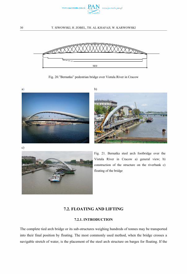
Fig. 20.”Bernatka” pedestrian bridge over Vistula River in Cracow
a) b)
c)
Fig. 21. Bernatka steel arch footbridge over the
Vistula River in Cracow a) general view; b)
construction of the structure on the riverbank c)
floating of the bridge
7.2. FLOATING AND LIFTING
7.2.1. INTRODUCTION
The complete tied arch bridge or its sub-structures weighing hundreds of tonnes may be transported
into their final position by floating. The most commonly used method, when the bridge crosses a
navigable stretch of water, is the placement of the steel arch structure on barges for floating. If the
30 T. SIWOWSKI, H. ZOBEL, TH. AL-KHAFAJI, W. KARWOWSKI
bridge is assembled in an area further away from its final position, then the complete structure can be
placed on barges to be transported from the assembly area to its final location. Tied arch bridges lend
themselves to placement of the complete bridge because their support reactions are uniquely vertical.
A temporary tie must be used during erection to stabilize arches that will not be tied in their final
state. Preassembly is only possible when there is sufficient space to construct the arches on the banks.
In urban environments, therefore, preassembly of the complete bridge is often difficult. The bridge is
commonly erected on one of the banks, parallel with the bank edge. This method is considered
economical because the work associated with erection of the arch is carried out on the ground, giving
easier access to the whole of the assembly area, with no need to use any special equipment.
7.2.2. “NETWORK” ARCH BRIDGE OVER THE DZIWNA RIVER TO CONNECT
WOLIN ISLAND WITH THE MAINLAND [18]
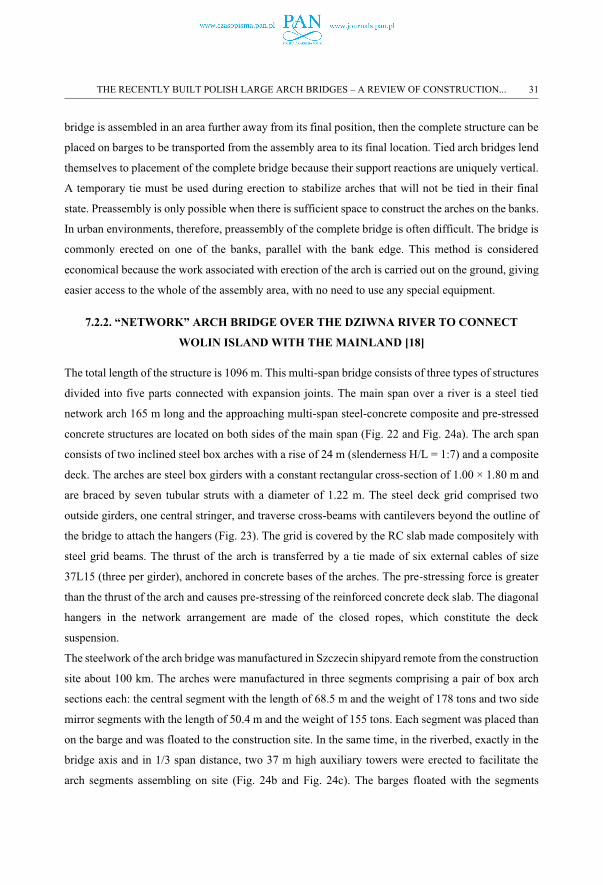
The total length of the structure is 1096 m. This multi-span bridge consists of three types of structures
divided into five parts connected with expansion joints. The main span over a river is a steel tied
network arch 165 m long and the approaching multi-span steel-concrete composite and pre-stressed
concrete structures are located on both sides of the main span (Fig. 22 and Fig. 24a). The arch span
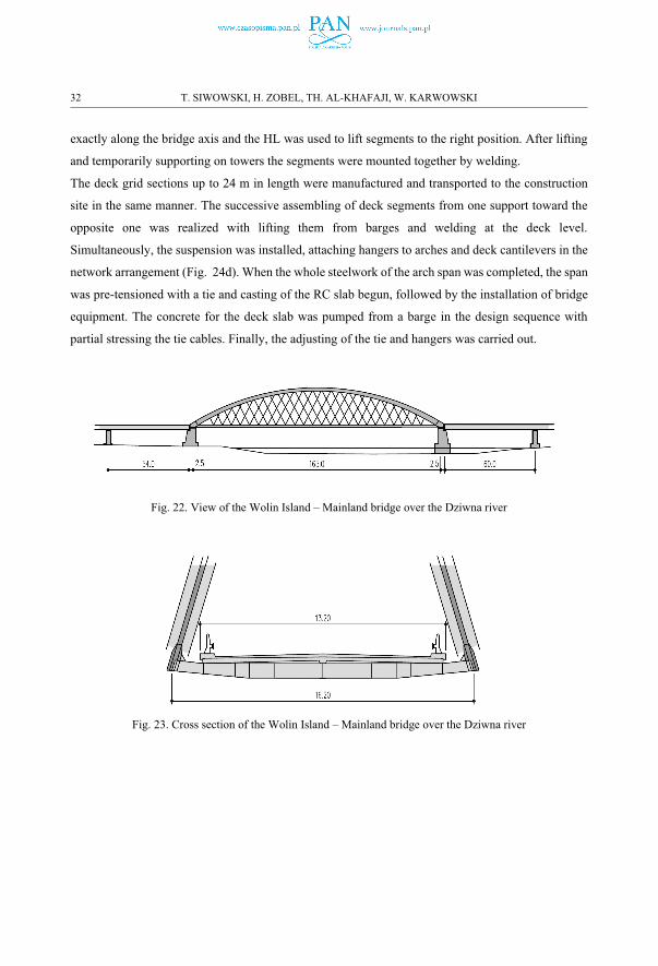
consists of two inclined steel box arches with a rise of 24 m (slenderness H/L = 1:7) and a composite
deck. The arches are steel box girders with a constant rectangular cross-section of 1.00 × 1.80 m and
are braced by seven tubular struts with a diameter of 1.22 m. The steel deck grid comprised two
outside girders, one central stringer, and traverse cross-beams with cantilevers beyond the outline of
the bridge to attach the hangers (Fig. 23). The grid is covered by the RC slab made compositely with
steel grid beams. The thrust of the arch is transferred by a tie made of six external cables of size
37L15 (three per girder), anchored in concrete bases of the arches. The pre-stressing force is greater
than the thrust of the arch and causes pre-stressing of the reinforced concrete deck slab. The diagonal
hangers in the network arrangement are made of the closed ropes, which constitute the deck
suspension.
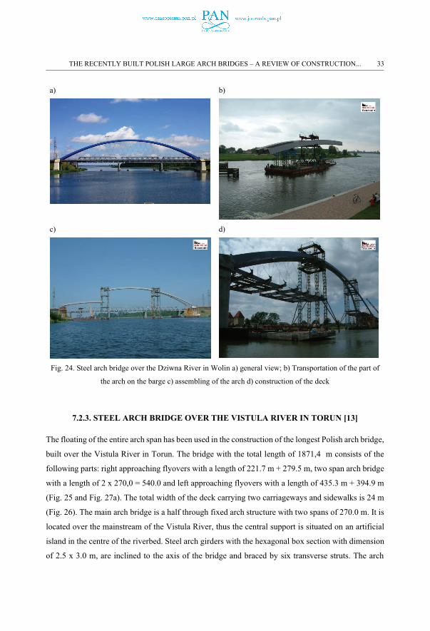
The steelwork of the arch bridge was manufactured in Szczecin shipyard remote from the construction
site about 100 km. The arches were manufactured in three segments comprising a pair of box arch
sections each: the central segment with the length of 68.5 m and the weight of 178 tons and two side
mirror segments with the length of 50.4 m and the weight of 155 tons. Each segment was placed than
on the barge and was floated to the construction site. In the same time, in the riverbed, exactly in the
bridge axis and in 1/3 span distance, two 37 m high auxiliary towers were erected to facilitate the
arch segments assembling on site (Fig. 24b and Fig. 24c). The barges floated with the segments
THE RECENTLY BUILT POLISH LARGE ARCH BRIDGES – A REVIEW OF CONSTRUCTION... 31
exactly along the bridge axis and the HL was used to lift segments to the right position. After lifting
and temporarily supporting on towers the segments were mounted together by welding.
The deck grid sections up to 24 m in length were manufactured and transported to the construction
site in the same manner. The successive assembling of deck segments from one support toward the
opposite one was realized with lifting them from barges and welding at the deck level.
Simultaneously, the suspension was installed, attaching hangers to arches and deck cantilevers in the
network arrangement (Fig. 24d). When the whole steelwork of the arch span was completed, the span
was pre-tensioned with a tie and casting of the RC slab begun, followed by the installation of bridge
equipment. The concrete for the deck slab was pumped from a barge in the design sequence with
partial stressing the tie cables. Finally, the adjusting of the tie and hangers was carried out.
Fig. 22. View of the Wolin Island – Mainland bridge over the Dziwna river
Fig. 23. Cross section of the Wolin Island – Mainland bridge over the Dziwna river
32 T. SIWOWSKI, H. ZOBEL, TH. AL-KHAFAJI, W. KARWOWSKI
a) b)
c) d)
Fig. 24. Steel arch bridge over the Dziwna River in Wolin a) general view; b) Transportation of the part of
the arch on the barge c) assembling of the arch d) construction of the deck
7.2.3. STEEL ARCH BRIDGE OVER THE VISTULA RIVER IN TORUN [13]
The floating of the entire arch span has been used in the construction of the longest Polish arch bridge,
built over the Vistula River in Torun. The bridge with the total length of 1871,4 m consists of the
following parts: right approaching flyovers with a length of 221.7 m + 279.5 m, two span arch bridge
with a length of 2 x 270,0 = 540.0 and left approaching flyovers with a length of 435.3 m + 394.9 m
(Fig. 25 and Fig. 27a). The total width of the deck carrying two carriageways and sidewalks is 24 m
(Fig. 26). The main arch bridge is a half through fixed arch structure with two spans of 270.0 m. It is
located over the mainstream of the Vistula River, thus the central support is situated on an artificial
island in the centre of the riverbed. Steel arch girders with the hexagonal box section with dimension
of 2.5 x 3.0 m, are inclined to the axis of the bridge and braced by six transverse struts. The arch
THE RECENTLY BUILT POLISH LARGE ARCH BRIDGES – A REVIEW OF CONSTRUCTION... 33
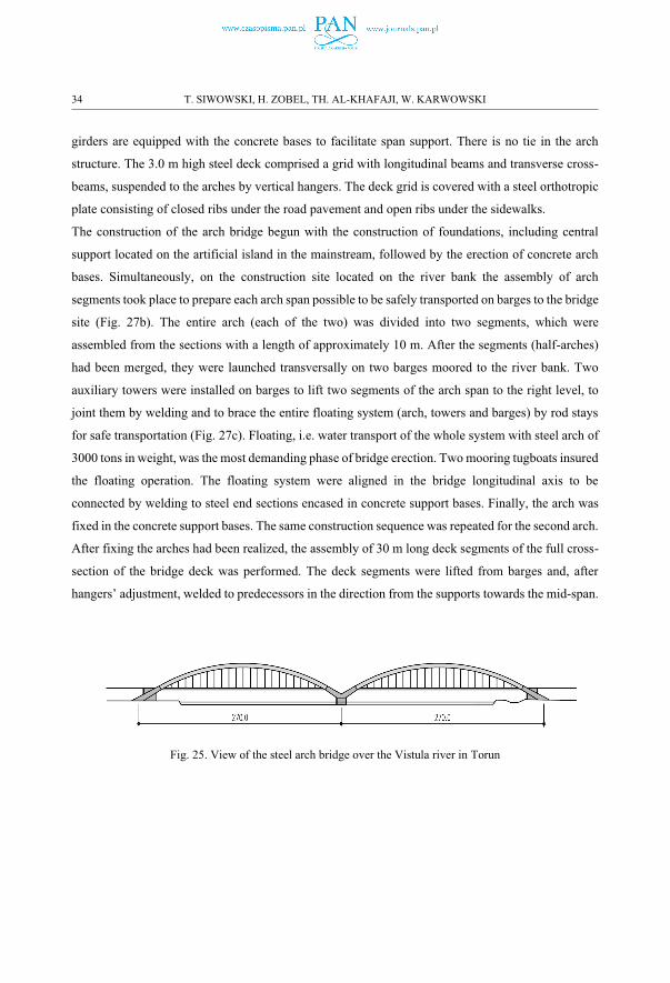
girders are equipped with the concrete bases to facilitate span support. There is no tie in the arch
structure. The 3.0 m high steel deck comprised a grid with longitudinal beams and transverse cross-
beams, suspended to the arches by vertical hangers. The deck grid is covered with a steel orthotropic
plate consisting of closed ribs under the road pavement and open ribs under the sidewalks.
The construction of the arch bridge begun with the construction of foundations, including central
support located on the artificial island in the mainstream, followed by the erection of concrete arch
bases. Simultaneously, on the construction site located on the river bank the assembly of arch
segments took place to prepare each arch span possible to be safely transported on barges to the bridge
site (Fig. 27b). The entire arch (each of the two) was divided into two segments, which were
assembled from the sections with a length of approximately 10 m. After the segments (half-arches)
had been merged, they were launched transversally on two barges moored to the river bank. Two
auxiliary towers were installed on barges to lift two segments of the arch span to the right level, to
joint them by welding and to brace the entire floating system (arch, towers and barges) by rod stays
for safe transportation (Fig. 27c). Floating, i.e. water transport of the whole system with steel arch of
3000 tons in weight, was the most demanding phase of bridge erection. Two mooring tugboats insured
the floating operation. The floating system were aligned in the bridge longitudinal axis to be
connected by welding to steel end sections encased in concrete support bases. Finally, the arch was
fixed in the concrete support bases. The same construction sequence was repeated for the second arch.
After fixing the arches had been realized, the assembly of 30 m long deck segments of the full cross-
section of the bridge deck was performed. The deck segments were lifted from barges and, after
hangers’ adjustment, welded to predecessors in the direction from the supports towards the mid-span.
Fig. 25. View of the steel arch bridge over the Vistula river in Torun
34 T. SIWOWSKI, H. ZOBEL, TH. AL-KHAFAJI, W. KARWOWSKI
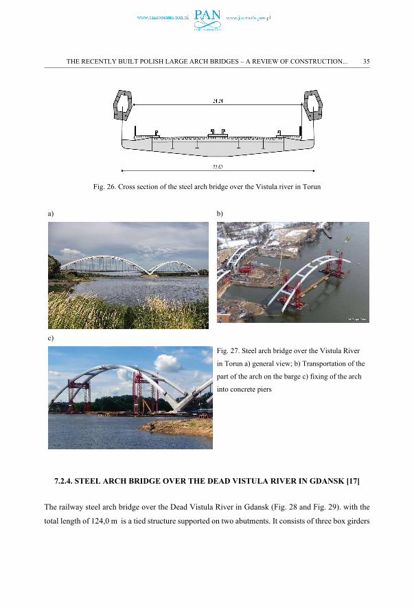
Fig. 26. Cross section of the steel arch bridge over the Vistula river in Torun
a) b)
c)
Fig. 27. Steel arch bridge over the Vistula River
in Torun a) general view; b) Transportation of the
part of the arch on the barge c) fixing of the arch
into concrete piers
7.2.4. STEEL ARCH BRIDGE OVER THE DEAD VISTULA RIVER IN GDANSK [17]
The railway steel arch bridge over the Dead Vistula River in Gdansk (Fig. 28 and Fig. 29). with the
total length of 124,0 m is a tied structure supported on two abutments. It consists of three box girders
THE RECENTLY BUILT POLISH LARGE ARCH BRIDGES – A REVIEW OF CONSTRUCTION... 35
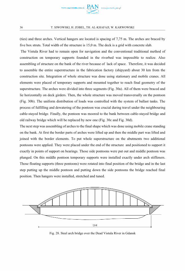
(ties) and three arches. Vertical hangers are located is spacing of 7,75 m. The arches are braced by
five box struts. Total width of the structure is 15,0 m. The deck is a grid with concrete slab.
The Vistula River had to remain open for navigation and the conventional traditional method of
construction on temporary supports founded in the riverbed was impossible to realize. Also
assembling of structure on the bank of the river because of lack of space. Therefore, it was decided
to assemble the entire superstructure in the fabrication factory (shipyard) about 30 km from the
construction site. Integration of whole structure was done using stationary and mobile cranes. All
elements were placed of temporary supports and mounted together to reach final geometry of the
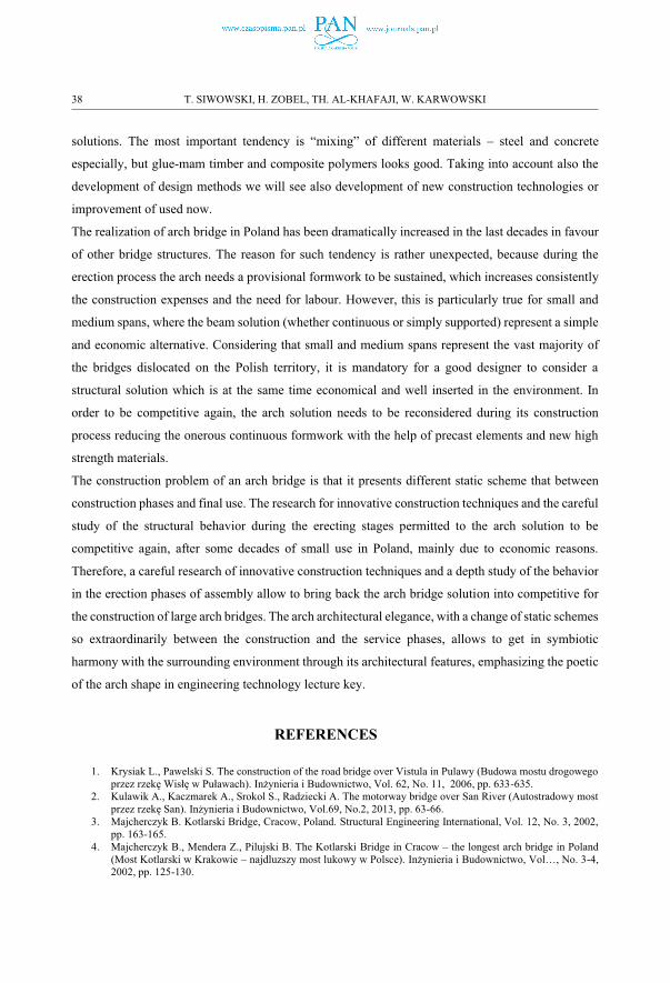
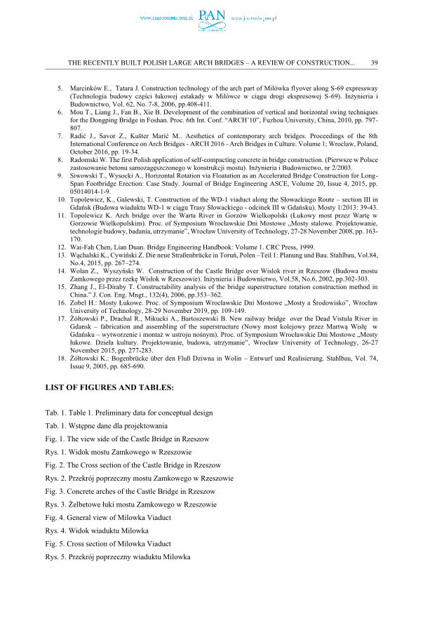
superstructure. The arches were divided into three segments (Fig. 30a). All of them were braced and
lie horizontally on deck girders. Then, the whole structure was moved transversally on the pontoon
(Fig. 30b). The uniform distribution of loads was controlled with the system of ballast tanks. The
process of fulfilling and dewatering of the pontoon was crucial during travel under the neighbouring
cable-stayed bridge. Finally, the pontoon was moored to the bank between cable-stayed bridge and
old railway bridge which will be replaced by new one (Fig. 30c and Fig. 30d).
The next step was assembling of arches to the final shape which was done using mobile crane standing
on the bank. At first the border parts of arches were lifted up and then the middle part was lifted and
joined with the border elements. To put whole superstructure on the abutments two additional
pontoons were applied. They were placed under the end of the structure and positioned to support it
exactly in points of support on bearings. Those side pontoons were put out and middle pontoon was
plunged. On this middle pontoon temporary supports were installed exactly under arch stiffeners.
Those floating supports (three pontoons) were rotated into final position of the bridge and in the last
step putting up the middle pontoon and putting down the side pontoons the bridge reached final
position. Then hangers were installed, stretched and tuned.
Fig. 28. Steel arch bridge over the Dead Vistula River in Gdansk
36 T. SIWOWSKI, H. ZOBEL, TH. AL-KHAFAJI, W. KARWOWSKI
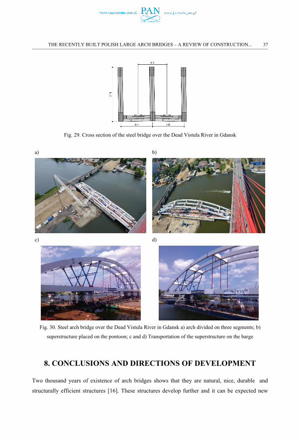
Fig. 29. Cross section of the steel bridge over the Dead Vistula River in Gdansk
a) b)
c) d)
Fig. 30. Steel arch bridge over the Dead Vistula River in Gdansk a) arch divided on three segments; b)
superstructure placed on the pontoon; c and d) Transportation of the superstructure on the barge
8. CONCLUSIONS AND DIRECTIONS OF DEVELOPMENT
Two thousand years of existence of arch bridges shows that they are natural, nice, durable and
structurally efficient structures [16]. These structures develop further and it can be expected new
THE RECENTLY BUILT POLISH LARGE ARCH BRIDGES – A REVIEW OF CONSTRUCTION... 37
solutions. The most important tendency is “mixing” of different materials – steel and concrete
especially, but glue-mam timber and composite polymers looks good. Taking into account also the
development of design methods we will see also development of new construction technologies or
improvement of used now.
The realization of arch bridge in Poland has been dramatically increased in the last decades in favour
of other bridge structures. The reason for such tendency is rather unexpected, because during the
erection process the arch needs a provisional formwork to be sustained, which increases consistently
the construction expenses and the need for labour. However, this is particularly true for small and
medium spans, where the beam solution (whether continuous or simply supported) represent a simple
and economic alternative. Considering that small and medium spans represent the vast majority of
the bridges dislocated on the Polish territory, it is mandatory for a good designer to consider a
structural solution which is at the same time economical and well inserted in the environment. In
order to be competitive again, the arch solution needs to be reconsidered during its construction
process reducing the onerous continuous formwork with the help of precast elements and new high
strength materials.
The construction problem of an arch bridge is that it presents different static scheme that between
construction phases and final use. The research for innovative construction techniques and the careful
study of the structural behavior during the erecting stages permitted to the arch solution to be
competitive again, after some decades of small use in Poland, mainly due to economic reasons.
Therefore, a careful research of innovative construction techniques and a depth study of the behavior
in the erection phases of assembly allow to bring back the arch bridge solution into competitive for
the construction of large arch bridges. The arch architectural elegance, with a change of static schemes
so extraordinarily between the construction and the service phases, allows to get in symbiotic
harmony with the surrounding environment through its architectural features, emphasizing the poetic
of the arch shape in engineering technology lecture key.
REFERENCES
1. Krysiak L., Pawelski S. The construction of the road bridge over Vistula in Pulawy (Budowa mostu drogowego przez rzekę Wisłę w Puławach). Inżynieria i Budownictwo, Vol. 62, No. 11, 2006, pp. 633-635.
2. Kulawik A., Kaczmarek A., Srokol S., Radziecki A. The motorway bridge over San River (Autostradowy most przez rzekę San). Inżynieria i Budownictwo, Vol.69, No.2, 2013, pp. 63-66.
3. Majcherczyk B. Kotlarski Bridge, Cracow, Poland. Structural Engineering International, Vol. 12, No. 3, 2002, pp. 163-165.
4. Majcherczyk B., Mendera Z., Pilujski B. The Kotlarski Bridge in Cracow – the longest arch bridge in Poland (Most Kotlarski w Krakowie – najdluzszy most lukowy w Polsce). Inżynieria i Budownictwo, Vol…, No. 3-4, 2002, pp. 125-130.
38 T. SIWOWSKI, H. ZOBEL, TH. AL-KHAFAJI, W. KARWOWSKI
5. Marcinków E., Tatara J. Construction technology of the arch part of Milówka flyover along S-69 expressway (Technologia budowy części łukowej estakady w Milówce w ciągu drogi ekspresowej S-69). Inżynieria i Budownictwo, Vol. 62, No. 7-8, 2006, pp.408-411.
6. Mou T., Liang J., Fan B., Xie B. Development of the combination of vertical and horizontal swing techniques for the Dongping Bridge in Foshan. Proc. 6th Int. Conf. “ARCH’10”, Fuzhou University, China, 2010, pp. 797-807.
7. Radić J., Savor Z., Kušter Marić M.. Aesthetics of contemporary arch bridges. Proceedings of the 8th International Conference on Arch Bridges - ARCH 2016 - Arch Bridges in Culture. Volume 1; Wroclaw, Poland, October 2016, pp. 19-34.
8. Radomski W. The first Polish application of self-compacting concrete in bridge construction. (Pierwsze w Polsce zastosowanie betonu samozagęszczonego w konstrukcji mostu). Inżynieria i Budownictwo, nr 2/2003.
9. Siwowski T., Wysocki A., Horizontal Rotation via Floatation as an Accelerated Bridge Construction for Long-Span Footbridge Erection: Case Study. Journal of Bridge Engineering ASCE, Volume 20, Issue 4, 2015, pp. 05014014-1-9.
10. Topolewicz, K., Galewski, T. Construction of the WD-1 viaduct along the Słowackiego Route – section III in Gdańsk (Budowa wiaduktu WD-1 w ciągu Trasy Słowackiego - odcinek III w Gdańsku). Mosty 1/2013: 39-43.
11. Topolewicz K. Arch bridge over the Warta River in Gorzów Wielkopolski (Łukowy most przez Wartę w Gorzowie Wielkopolskim). Proc. of Symposium Wrocławskie Dni Mostowe „Mosty stalowe. Projektowanie, technologie budowy, badania, utrzymanie”, Wrocław University of Technology, 27-28 November 2008, pp. 163-170.
12. Wai-Fah Chen, Lian Duan. Bridge Engineering Handbook: Volume 1. CRC Press, 1999.13. Wąchalski K., Cywiński Z. Die neue Straßenbrücke in Toruń, Polen –Teil 1: Planung und Bau. Stahlbau, Vol.84,
No.4, 2015, pp. 267–274.14. Wolan Z., Wyszyński W. Construction of the Castle Bridge over Wislok river in Rzeszow (Budowa mostu
Zamkowego przez rzekę Wisłok w Rzeszowie). Inżynieria i Budownictwo, Vol.58, No.6, 2002, pp.302-303.15. Zhang J., El-Diraby T. Constructability analysis of the bridge superstructure rotation construction method in
China.” J. Con. Eng. Mngt., 132(4), 2006, pp.353–362. 16. Zobel H.: Mosty Łukowe. Proc. of Symposium Wrocławskie Dni Mostowe „Mosty a Środowisko”, Wrocław
University of Technology, 28-29 November 2019, pp. 109-149.17. Żółtowski P., Drachal R., Mikucki A., Bartoszewski B. New railway bridge over the Dead Vistula River in
Gdansk – fabrication and assembling of the superstructure (Nowy most kolejowy przez Martwą Wisłę w Gdańsku – wytworzenie i montaż w ustroju nośnym). Proc. of Symposium Wrocławskie Dni Mostowe „Mosty łukowe. Dzieła kultury. Projektowanie, budowa, utrzymanie”, Wrocław University of Technology, 26-27 November 2015, pp. 277-283.
18. Żółtowski K.: Bogenbrücke über den Fluß Dziwna in Wolin – Entwurf und Realisierung. Stahlbau, Vol. 74, Issue 9, 2005, pp. 685-690.
LIST OF FIGURES AND TABLES:
Tab. 1. Table 1. Preliminary data for conceptual design
Tab. 1. Wstępne dane dla projektowania
Fig. 1. The view side of the Castle Bridge in Rzeszow
Rys. 1. Widok mostu Zamkowego w Rzeszowie
Fig. 2. The Cross section of the Castle Bridge in Rzeszow
Rys. 2. Przekrój poprzeczny mostu Zamkowego w Rzeszowie
Fig. 3. Concrete arches of the Castle Bridge in Rzeszow
Rys. 3. Żelbetowe łuki mostu Zamkowego w Rzeszowie
Fig. 4. General view of Milowka Viaduct
Rys. 4. Widok wiaduktu Milowka
Fig. 5. Cross section of Milowka Viaduct
Rys. 5. Przekrój poprzeczny wiaduktu Milowka
THE RECENTLY BUILT POLISH LARGE ARCH BRIDGES – A REVIEW OF CONSTRUCTION... 39
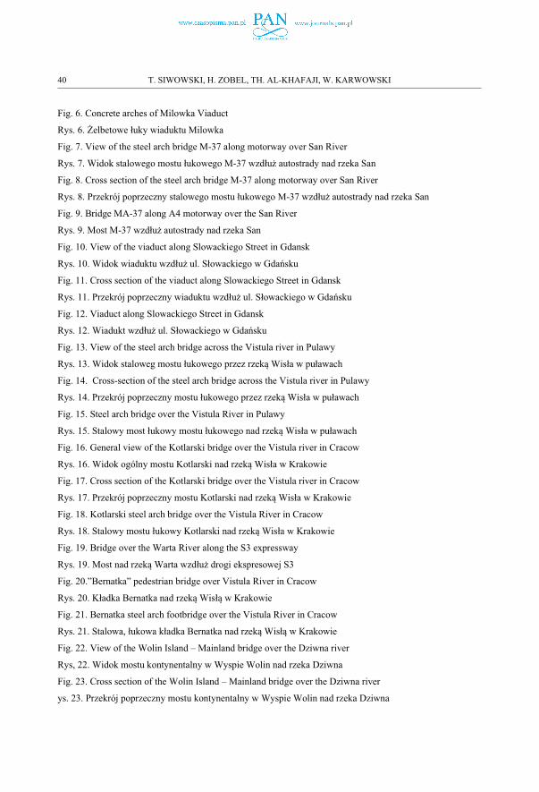
Fig. 6. Concrete arches of Milowka Viaduct
Rys. 6. Żelbetowe łuky wiaduktu Milowka
Fig. 7. View of the steel arch bridge M-37 along motorway over San River
Rys. 7. Widok stalowego mostu łukowego M-37 wzdłuż autostrady nad rzeka San
Fig. 8. Cross section of the steel arch bridge M-37 along motorway over San River
Rys. 8. Przekrój poprzeczny stalowego mostu łukowego M-37 wzdłuż autostrady nad rzeka San
Fig. 9. Bridge MA-37 along A4 motorway over the San River
Rys. 9. Most M-37 wzdłuż autostrady nad rzeka San
Fig. 10. View of the viaduct along Slowackiego Street in Gdansk
Rys. 10. Widok wiaduktu wzdłuż ul. Słowackiego w Gdańsku
Fig. 11. Cross section of the viaduct along Slowackiego Street in Gdansk
Rys. 11. Przekrój poprzeczny wiaduktu wzdłuż ul. Słowackiego w Gdańsku
Fig. 12. Viaduct along Slowackiego Street in Gdansk
Rys. 12. Wiadukt wzdłuż ul. Słowackiego w Gdańsku
Fig. 13. View of the steel arch bridge across the Vistula river in Pulawy
Rys. 13. Widok staloweg mostu łukowego przez rzeką Wisła w puławach
Fig. 14. Cross-section of the steel arch bridge across the Vistula river in Pulawy
Rys. 14. Przekrój poprzeczny mostu łukowego przez rzeką Wisła w puławach
Fig. 15. Steel arch bridge over the Vistula River in Pulawy
Rys. 15. Stalowy most łukowy mostu łukowego nad rzeką Wisła w puławach
Fig. 16. General view of the Kotlarski bridge over the Vistula river in Cracow
Rys. 16. Widok ogólny mostu Kotlarski nad rzeką Wisła w Krakowie
Fig. 17. Cross section of the Kotlarski bridge over the Vistula river in Cracow
Rys. 17. Przekrój poprzeczny mostu Kotlarski nad rzeką Wisła w Krakowie
Fig. 18. Kotlarski steel arch bridge over the Vistula River in Cracow
Rys. 18. Stalowy mostu łukowy Kotlarski nad rzeką Wisła w Krakowie
Fig. 19. Bridge over the Warta River along the S3 expressway
Rys. 19. Most nad rzeką Warta wzdłuż drogi ekspresowej S3
Fig. 20.”Bernatka” pedestrian bridge over Vistula River in Cracow
Rys. 20. Kładka Bernatka nad rzeką Wisłą w Krakowie
Fig. 21. Bernatka steel arch footbridge over the Vistula River in Cracow
Rys. 21. Stalowa, łukowa kładka Bernatka nad rzeką Wisłą w Krakowie
Fig. 22. View of the Wolin Island – Mainland bridge over the Dziwna river
Rys, 22. Widok mostu kontynentalny w Wyspie Wolin nad rzeka Dziwna
Fig. 23. Cross section of the Wolin Island – Mainland bridge over the Dziwna river
ys. 23. Przekrój poprzeczny mostu kontynentalny w Wyspie Wolin nad rzeka Dziwna
40 T. SIWOWSKI, H. ZOBEL, TH. AL-KHAFAJI, W. KARWOWSKI
Fig. 24. Steel arch bridge over the Dziwna River in Wolin
Rys. 24. Stalowy most łukowy nad rzeka Dziwna w Wolinie
Fig. 25. View of the steel arch bridge over the Vistula river in Torun
Rys. 25. Widok stalowego mostu łukowego nad Wisłą w Toruniu
Fig. 26. Cross section of the steel arch bridge over the Vistula river in Torun
Rys. 26. Przekrój poprzeczny stalowego mostu nad Wisłą w Toruniu
Fig. 27. Steel arch bridge over the Vistula River in Torun
Rys. 27. Stalowy most Łukowy nad Wisłą w Toruniu
Fig. 28. Steel arch bridge over the Dead Vistula River in Gdansk
Rys. 28. Stalowy most łukowy nad martwą Wisłą w Gdańsku
Fig. 29. Cross section of the steel bridge over the Dead Vistula River in Gdansk
Rys. 29. Przekrój poprzeczny stalowego mostu nad martwą Wisłą w Gdańsku
Fig. 30. Steel arch bridge over the Dead Vistula River in Gdansk
Rys. 30. Stalowy most łukowy nad martwą Wisłą w Gdańsku
OSTATNIO WYBUDOWANE MOSTY ŁUKOWE DUŻYCH ROZPIĘTOŚCI – PRZEGLĄD
TECHNOLOGII WYKONANIA
Słowa kluczowe: most, wiadukt, most łukowy, technologie wykonania
STRESZCZENIE
Mosty łukowe są budowane od więcej niż dwóch tysięcy lat. W Europie ten typ konstrukcji jako pierwsi zastosowali
Rzymianie. Niezależnie od nich mosty łukowe zaczęli w tym samym czasie budować Chińczycy. Materiałem
konstrukcyjnym aż do epoki Renesansu był kamień (granit, piaskowiec, marmur). Mosty kamienne były budowane
jeszcze w XIX wieku, a nawet są budowane jeszcze obecnie, choć sporadycznie. Jeszcze w Średniowieczu pojawiły się
konstrukcje ceglane, które stopniowo zastępowały kamień, ale ich rozkwit nastąpił wraz z budową linii kolejowych.
Koniec XVIII wieku to początek budowy mostów stalowych, najpierw żeliwnych, a od lat 20-tych XIX wieku
wykonywanych ze stali zgrzewnej. W latach 50-tych tego wieku opanowano produkcję stali zlewnej, która jest
produkowana do dzisiaj, tyle, że zdecydowanie o innych właściwościach fizyko – mechanicznych. Koniec XIX wieku to
z kolei początek budowy konstrukcji betonowych i żelbetowych.
Wiek XX przyniósł rozwój nowych materiałów, co znalazło także swój wyraz w projektowaniu i budowie mostów
łukowych. Jeszcze przed II wojną światową pojawiły się mosty łukowe z elementami sprężonymi oraz mosty aluminiowe.
Mosty z drewna klejonego to już lata 50-te XX wieku, a od 1982 roku rozpoczęto stosowanie kompozytów polimerowych
jako materiału konstrukcyjnego.
THE RECENTLY BUILT POLISH LARGE ARCH BRIDGES – A REVIEW OF CONSTRUCTION... 41
Także wykorzystywane od dawna materiały takie jak stal i beton modyfikowano, co zaowocowało budową mostów
łukowych ze stali nierdzewnej. Połączono również oba wyżej wymienione materiały dając możliwość budowy konstrukcji
hybrydowych jak np. stalowych mostów łukowych z elementów zamkniętych wypełnionych betonem. Od pewnego czasu
standardem stało się łączenie różnych materiałów w różnych elementach konstrukcji np. łuk stalowy z pomostem
kompozytowym czy łuk drewniany z pomostem typu drewno –beton.
Jest wiele kryteriów klasyfikacji mostów łukowych. Kryterium materiałowe, użytkowe a także rodzaj przeszkody
komunikacyjnej są najprostsze i najbardziej oczywiste nawet nie dla inżyniera. Natomiast z punktu widzenia projektanta
i wykonawcy kluczowa rolę odgrywa schemat statyczny (bezprzegubowy, dwuprzegubowy czy trójprzegubowy) co
determinuje sposób przenoszenia siły rozporowej do gruntu albo bezpośrednio do gruntu (tzw. luk rozporowy) albo za
pośrednictwem klasycznych podpór mostowych (tzw. łuk ze ściągiem). Istotnym kryterium jest także stosunek
sztywności łuku do sztywności pomostu.
Przekazanie sił z pomostu na łuk w konstrukcjach łukowych z „jazdą pośrednią” i z „jazdą dołem” wymaga zastosowania
elementów łącznikowych, pracujących jako rozciągane. Nazwą powszechnie używaną są wieszaki. Wykonanie
wieszaków wymaga zastosowania elementów o dużej wytrzymałości na rozciąganie oraz odpowiedniego połączenia ich
z łukiem oraz pomostem obiektu.
Współczesne mosty łukowe zazwyczaj wykorzystują wieszaki wykonane jako prętowe, linowe (z lin zamkniętych lub
wielosplotowych) oraz z kształtowników stalowych. Znane są także obiekty wyposażone wieszaki żelbetowe oraz
sprężone. Wykonano także eksperymentalne obiekty z wieszakami z materiałów kompozytowych.
Wymienione wyżej uwarunkowania, a także inne tu nie wspomniane determinują wybór metody budowy. Technologie
budowy mostów łukowych nie różnią się istotnie od stosowanych przy innych typach mostów. Można wymienić
następujące najczęściej stosowane:
� montaż dźwigiem całej konstrukcji scalonej wcześniej na placu budowy,
� montaż na rusztowaniach,
� nasuwanie z lub bez tymczasowych podpór pośrednich (podłużnie lub poprzecznie do osi mostu),
� metoda wspornikowa (nawisowa) z lub bez wspomagania odciągami,
� montaż z użyciem barek.
W przypadku konstrukcji betonowych (dźwigarów, elementów pomostu) bardzo istotną sprawą jest zaprojektowanie i
zrealizowanie procesu betonowania. Jest on kluczowy z punktu widzenia odkształceń łuku oraz elementów pomostu, w
szczególności płyty pomostu.
Decydującymi czynnikami są:
� kolejność betonowania,
� długość betonowanych fragmentów,
� grubość betonowanych warstw,
� liczba i wielkość przerw technologicznych.
Z kolei te czynniki są ściśle powiązane z recepturą betonu, która w decydujący sposób wpływa na szybkość wiązania
betonu i co za tym idzie czas uzyskiwania potrzebnej wytrzymałości, a to w konsekwencji przekłada się na czas realizacji
inwestycji.
Osobnym zagadnieniem jest montaż wieszaków (słupków, ścian). W tradycyjnych konstrukcjach łukowych, jak już to
wspomniano wyżej były to pręty obetonowane w betonowych mostach łukowych i składające się z kształtowników w
przypadku mostów stalowych. Były one łączone „na sztywno” z konstrukcją łuków i pomostem. Nie było możliwości ich
42 T. SIWOWSKI, H. ZOBEL, TH. AL-KHAFAJI, W. KARWOWSKI

naciągu (kontrolowanego wprowadzenia odpowiedniej wartości sił). W chwili obecnej praktycznie budowniczowie
odeszli od takich konstrukcji i stosuje się albo pręty sprężające albo cięgna wiotkie (kable sprężające). W konsekwencji,
w zależności od przyjętego systemu mocowania stosuje się zakotwienia bierne lub czynne. W pierwszym przypadku
naciąg jest możliwy przy zastosowaniu tzw. śrub rzymskich. Natomiast w drugim naciąg wykonuje się za pomocą pras.
Podstawowym problemem w budowie mostów, w tym i lukowych) jest fakt, że praktycznie zawsze schemat statyczny
konstrukcji w trakcie budowy i konstrukcji finalnej różni się diametralnie. Dlatego tak ważna, choć często traktowana
pobieżnie, jest analiza pracy konstrukcji w stanach montażowych.
Received: 14.07.2020, Revised: 15.09.2020
THE RECENTLY BUILT POLISH LARGE ARCH BRIDGES – A REVIEW OF CONSTRUCTION... 43