Embed Size (px)
Citation preview

▲177The Journal of The South African Institute of Mining and Metallurgy JULY 2001
Introduction
The Impala No. 1A ventilation shaft is located approximately15 kms north of Rustenburg and is accessed via the R510road from Rustenburg to Northam/Thabazimbi. Thissituation is shown on the location plan in Figure 1. Thegeology at the site consists of an upper layer of black turf ofabout 1 metre in thickness, grading into weathered norite.The depth of weathering is generally less than 5 metres.Zones of deeper weathering may occur along fracture zonesassociated with faults and dykes. Groundwater occurs mainlywithin the weathered/fractured aquifer system.
The ventilation shaft is a 5.1 m diameter upcast shaft,and forms part of a system of ventilation shafts tocomplement the existing infrastructure as mining progressesdown the new twin decline extension of Impala 1 shaft. Theprincipal reason for these shafts is to lessen the risk of anextended RAW and also to counter the effects of the heatbuild-up as the mining goes deeper, with the resultant effectthat the existing cooling centre (fridge plant) becomes moreremote from activities.
The No. 1A shaft (upcast) is positioned approximately1,2 km on down dip from the main shaft and the No. 1Bshaft (downcast) approximately 1,2 km further. Geologicalinformation was used from a borehole 1,2 km away on strikefrom the upcast shaft. The first shaft (1A) is a 5,1 mdiameter hole to be fitted with two 2,2 MW fans, whilst thesecond shaft (1B) is 4,1 m diameter to accommodate a 7MWfridge plant.
BackgroundIn October 1998, consultants were called in to investigate thefeasibility of pre-cementation to control groundwater inflowinto the proposed ventilation shaft No. 1A at Impala PlatinumMine. This was as a result of serious water ingress and lossof circulation encountered whilst drilling a 250 mm pilot holefor the proposed shaft. Volumes of up to 40m3/h werereportedly pumped from the pilot borehole during drillingwith very little drawdown resulting.
It had been decided to raise-bore the shafts foreconomical as well as time-related reasons, specifically asthey were both required for ventilation purposes only. Theraise-bore chips could then also be handled better and moreeasily through the existing infrastructure underground.
The objective of the consultants, investigation was toidentify the geological features that influenced groundwaterflow to the proposed shaft and assess the feasibility ofblocking the groundwater movement by pre-cementation.
Four holes ranging in depth from 40 m to 80 m weredrilled. These holes were sited at the corners of the concreteblock, whilst in addition, the mine drilled 12 holes tofacilitate grouting around the pilot hole. The formation
underlying the site was found to be highly fractured andweathered particularly in the zone from surface to a depth ofabout 40 m. Serious problems of hole collapse and loss ofcirculation were experienced in this zone during drilling.Below 40 m the formation becomes more competent withlocalized fractures and weathering to a depth of about 60 m.The depth and degree of fracturing and weathering generallyincreased diagonally across the collar. Cementitious groutingwas carried out around the pilot hole to stop loss of drillwater circulation and groundwater inflow into the hole. Thiswas carried out in order to facilitate drilling to the targetdepth of over 1000 m. Grout was injected into the groundthrough twelve holes within a radius of seven metres roundthe pilot hole.
The extensive tests carried out confirmed that a detailedhydrological assessment of the conditions would be requiredtogether with a proposal for water sealing before the raise-boring could take place. The proposal which was acceptedconsisted of a series of holes in a circular pattern around theshaft to create a curtain. Differential curtain grouting waseffected with Tube-Manchets for additional assessment ofsealing, and also to provide the facility to reseal again if theneed arose. This method was implemented until a lusionvalue of less than seven was achieved.
The main contractor Rucbor was called back to site tocontinue with the raise-boring, however, ingress of sub-surface water (in the region of 10 litres/second) were stillbeing experienced through the sidewalls as the reamer headground its way to the surface. It was evident that the sealingof the sidewall had been washed away, causing major falls ofground in the process.
A platform was built to assess the damage to the shaftcaused by the rockfalls and also to allow construction of amini-headgear for possible rehabilitation. A video camerawas then lowered to allow viewing of the inside of the shaftand to judge the extent of sidewall damage. This allowed fora more advised decision on the repair of the sidewall.
Rehabilitation proposal
The ventilation shaft had been raise-bored with the concretecollar being installed to approximately 4 metres belowground level, and although designed as an upcast ventilationshaft, the air extraction system currently being utilizedunderground on the rest of the mine turned the shaft into a
The rehabilitation of Impala No. 1Aventilation shaftby A. Bothma*
* Impala Platinum Mines.© The South African Institute of Mining and Metallurgy, 2001. SA ISSN
0038–223X/3.00 + 0.00. First presented at SAIMM Colloquium:Shotcrete and membrane support, Apr. 2001.

The rehabilitation of Impala No. 1A ventilation shaft
downcast shaft. Rock falls if in sufficient quantity or ifallowed to build up to such an extent that the shaft becameblocked at the bottom, immediately turned the shaft into anupcast situation, with air being forced up at a high velocity.
Rucmin were then contracted to execute the rehabilitationworks using a ‘stage’ suspended from four Skyjacks and acage suspended from two Skyjacks. This equipment wassuitable to inspect the shaft to a depth of 100 m, althoughearly indications were that it would only be necessary to goto a depth of 60 m.
The lightweight, single deck stage was suspended in theshaft by means of six ‘Skyjack’ winches attached to theheadframe. Ropes of 9 mm diameter were attached to thestage whilst the design of the control circuits was such thatthe winches could be operated either in unison orindividually to enable levelling of the stage. The stage couldbe raised or lowered at a speed of 6 m per minute. In additionto the ‘live’ ropes, an additional six overspeed ropes werehung from the headframe and passed through the stage. Theoverspeed ropes ran through brake blocks attached to thestage and were designed to prevent a runaway should theskyjack winches fail for any reason. A service cage wasinstalled for personnel access as well as the possiblemovement of the materials to the stage. This also ran on‘Skyjack’ winches with guide rails being installed on bracketsat 3 m centres.
Figure 2 shows the small headgear which wasconstructed to facilitate the rehabilitation work.
Grouting from the surface around the periphery of theshaft had not prevented the ingress of high volumes of sub-surface water from penetrating the shaft therefore analternative approach was decided upon which entailed thefollowing:
➤ Application of a primary shotcrete layer to the shaftsubstrate
➤ The installation of 3-metre anchor bolts➤ Subsequently, the introduction of a low pressure grout
through the shotcrete to seal the fissures in the rockconveying the water
➤ The application of the final layer of shotcrete.The shotcrete method proposed was the wet method, with
Geopractica employed to provide the critical mix design, mixand pump the shotcrete underground, as well as carry out theQA and QC programmes which were essential for the project.MBT Mining and Tunnelling were consulted with respect tothe chemical additives to be incorporated in the mix withspecific regard to the wet conditions existing. In addition,they provided the equipment, shotcrete application trainingas well as the normal back-up service commensurate with theproduct supply.
Contract methodology
The condition of the shaft was poor due to the deteriorationof the rock as a direct result of the water, therefore it wasnecessary to stabilize the sides of the shaft in the quickestmanner, thus reducing the exposure time to the possibility ofrock falls. It was agreed that the operations that satisfiedthese criteria the most were the barring down and washingdown of the face followed immediately with the spraying of afibre-reinforced shotcrete layer of 75 mm, being equivalent tohalf the total thickness specified.
Once this work had been executed the installation ofanchor bolts would follow, thus enhancing the stability of theshaft. On completion of the anchor bolts, the safety in theshaft was considered suitable for the relatively slowprocedure of drilling and grouting to seal the fissuresconveying the water.
After completion of these operations to an agreedposition, where water ingress was negligible or considerablyreduced, the second shotcrete layer, making up the totalthickness was applied. This second layer covered the anchorbolt heads to protect them from erosion.
The application of the primary layer of shotcreteproceeding downwards from the collar resulted in thepressure of the sub-surface water increasing to such anextent that channelling of the water away from the surface tobe sprayed was required.
This contract methodology was agreed upon by theparties concerned. However, due to the prevailing conditions,certain amendments or ‘fine tuning’ would almost certainlybe required as the work progressed.
▲
178 JULY 2001 The Journal of The South African Institute of Mining and Metallurgy
Figure 1. Impala Platinum—Rustenburg No. 1B shaft—locality plan
Figure 2—Headgear at No. 1A vent shaft

Mix requirements/design
It was decided at the commencement of discussions that dueto the shaft conditions and the limiting parameters, the wetshotcrete process would be used.
This process would give a constant water/cement ratiowhich would also allow a controlled quality mix. This wasessential in these conditions. Due to the controlled mix,improved bonding to the substrate as well as highercompressive strengths could be achieved with very littlevariation to results.
The wet shotcrete process also lends itself to the use ofnew admixture technologies which would then allow the 75mm layer thickness to be applied in a single pass without anyproblem.
The shotcrete design had to comply with the followingparameters:
➤ Compressive strength (cubes) minimum 50 MPa➤ In situ compressive strength (cores) minimum 30 MPa➤ Energy absorption minimum 700 Joules ➤ The mix design must incorporate 40 mm minimum
length polypropylene fibre➤ The mix must be eminently pumpable➤ The mix must be capable of being sprayed in wet
conditions.An additional requirement of the mine was that the work
must commence within two weeks.These specifications and conditions required that a
proven mix design be used, as insufficient time existed tocarry out a mix design with locally available materials. Atthat stage all shotcreting being carried out locally was by thedry process, and no performance data for any of these mixeswas available. Owing to these reasons, it was decided to usea shotcrete base mix design similar to that which wascurrently in use at South Deep Mine.
The original mix design for South Deep Mineincorporated steel fibre and was developed by Mr A. Parrish,then of Anglo American Technical Services, to accommodateconditions similar to those existing at Impala, being:
➤ Ingress of high volumes of sub-surface water➤ Reduced permeability➤ High bond strength with substrate➤ High tensile strength➤ High energy absorption values.
The base mix affects the tensile strength and energyabsorption however, the type and quantity of fibre has by farthe greatest influence on these characteristics. A fibresatisfying these parameters had to be selected for incorpo-ration with this design.
It was decided that the mix characteristics were suitableto pump and spray a 50 mm monofilament polypropylenefibre, over the distances required (± 80 m) which wasanother reason for the selection of the base mix. Practicaltests were carried out at MBT’s premises to ensure that theexpected pumpability could be satisfied. Minor modificationswere made to the base mix as a result of these trials.
Shotcrete mix design
Description Quantity per cubic metre6.7 mm stone 262 kgCrusher sand 1080 kgPlaster sand 160 kgCem 1 52,5 Cement 475 kgCondensed silica fume 38 kgSuper pozz (micro fine fly ash) 75 kg
Superplasticizer (Glenium 51) 4.20 litresStabilizer (Delvocrete) 3.64 litresInternal curing agent (Meyco TCC 735) 5.60 litresAccelerator (Meyco SA 160) VariesMicro fibre 0.91 kg50 mm monofilament polypropylene fibre 7.5 kgTotal water 200Water/Cement Ratio 0.34Flow 550–600 mm
It should be noted that the design strength of this mixwas higher than required, however, with the large quantitiesof sub-surface water encountered on the substrate, highaccelerator dosages were required to accelerate the mix. Theaccelerator also contains approximately 60% water. Thecombination of the above two additional sources of water hasa serious impact on the water/cement ratio of the mixedshotcrete, reducing the compressive strength considerably.
Materials for the shotcrete
The materials used were as detailed below and delivered inthe manner described.
Aggregate
The aggregate mix was factory blended as per the mix designand delivered in bags with a mass of approximately 23 kg.This translated to 75 sacks of aggregate per cubic metre ofshotcrete.
Cementitious material The cementitious material comprising of cement, condensedsilica fume and super pozz were pre-blended by mass anddelivered in bags containing approximately 23 kg. Twenty-five bags of cementitious material were required tomanufacture 1 m3 of shotcrete.
FibreThe monofilament polypropylene fibre specified ismanufactured from high performance polymer and specif-ically shaped to resist matrix pull out. The non-corrosivecharacteristics was obviously one of the main reasons for thespecification, whilst the 50 mm length gave the requiredenergy absorption characteristics. The fibres were deliveredin boxes containing 9 kg and the specified batch mass wasweighed out on site. The microfibre was premixed into thebags containing the aggregate at the required ratio.
Additives
All additives were delivered to site in 220 litre drumsenabling the required quantities to be tapped off accordingly.The following additives were used which considerablyenhanced the mix performance and certainly contributed toboth the application and quality of the final product:
➤ Superplasticizer (Glenium 51)—This was used to givethe required consistency for spraying and to aidpumpability as well as allowing significant waterreduction and hence a higher compressive strength.
➤ Stabiliser (Delvocrete)—This product is a hydrationcontrol admixture which maintains the workability ofthe mix and extends the open time duringtransportation and application without reducingconcrete quality. In this instance where 50 mmdiameter steel pipes were used down the shaft and thetotal pumping distance varied to over 80 m, thisproduct was invaluable.
The rehabilitation of Impala No. 1A ventilation shaft
▲179The Journal of The South African Institute of Mining and Metallurgy JULY 2001

The rehabilitation of Impala No. 1A ventilation shaft
➤ Internal Curing Agent (Meyco TCC 735)—This is aparticular admixture added to sprayed concrete toimprove the bond with the substrate as well as to assistthe curing cycle of concrete where traditional curingmethods cannot be used.
➤ Accelerator (Meyco SA 160)—This is an alkali-freeaccelerator which improves concrete durability andallows the spraying of large thicknesses in a singlepass. The dosage can be adjusted to ensure goodcohesion between layers.
Equipment selection
Enquiries revealed that no Ready Mix concrete suppliers hadwet mixing facilities in the area. Furthermore, experience hasshown that the mixing of shotcrete in a Ready Mix truck isunacceptable as insufficient shear is imparted to the mix.This in turn increases the quantity of water incorporated inthe mix for a given flow. Based on these facts the supply ofpremixed shotcrete from commercial sources in the area waseliminated.
As the conditions dictated that the shotcrete had to beapplied by the wet process, it was necessary to mix theshotcrete at the mine on surface, and pump the material up to70 metres underground. The capacity of the stage wasinsufficient to accommodate anything more than the labour,accelerator pump, accelerator as well as small tools andequipment.
The equipment selection made was a V300 Pan mixer(200 litre yield wet) together with a Coretta positivedisplacement pump which was capable of pumping therequired distance as well as at the required rate. The twounits were matched in terms of the output of the mixer intothe hopper of the pump with a suitable loading platformconstructed to enable productive loading of the mixer (seeFigures 3 and 4).
Communications between the nozzle operator on thestage and the mixer and pump operators were via phone andsignal bells. In order to transport the concrete from the pumpto the area of application down the shaft, a combination of50 mm diameter steel pipes and flexible delivery andspraying hoses were used. The brackets on the guide railsfixed in the shaft also supported the cables, air and waterreticulation as well as the 50 mm diameter steel pipe line forthe shotcrete.
Shotcrete operation
This section will cover the basic work programme, the initial
preparation of the substrate prior to spraying, the mixing andpumping of the shotcrete as well as the applicationprocedures.
Work programme
The original programme for the work dictated that two shiftswould have to be worked to tie in with the overall workprogramme. The works were commenced in the middle ofwinter, and this combined with the fact that the shaft wassucking air down, caused the sub-surface water to freeze onthe substrate resulted in all night work having to beabandoned. (Temperature of -9° centigrade).
In addition to the freezing of the water in the shaft, thechemicals used in the shotcrete mix required that they bekept at a minimum of 5°C, thus restricting the time availablefor mixing. Water for the mixing was supplied from aborehole and stored in a tank which gravity fed the mixer.The water also froze in the storage tank overnight whichaffected the time that mixing could commence. Acombination of the above facts dictated the period of mixingdaily.
The temperature conditions also meant that personnelhad to be equipped with special cold weather gear, whilst thelubrication oil for the rockdrills had to be kept in the concretecube bath to prevent the rockdrills freezing.
Preparation of substrate
The substrate was first prepared by the barring of loose rockand cleaning with water at high pressure where required.This operation was not easily executed, as the barring off ofany loose rock had to be carried out below the bottom of thestage to prevent a rock fall onto the stage.
As the first shotcrete layer progressed downwards thepressure of the sub-surface water increased considerably,necessitating the following measures.
➤ Installation of kerb rings to cut off sub-surface waterflowing down the face of the substrate. The kerb ringwas made up out of sheet metal and bent to the shaperequired forming a gutter. This ring terminated with arubber pipe draining the water collected, away from thesubstrate to be sprayed.
➤ Introduction of pipes into fissures where the flow ofwater was concentrated in order to divert the waterfrom the substrate. This was carried out by drilling intothe fissures and inserting 25 mm diameter rubber hose
▲
180 JULY 2001 The Journal of The South African Institute of Mining and Metallurgy
Figure 3—Mix Batching
Figure 4—Mix batching
pipes. The hose pipes were held in place by acementitious product that sets quickly in the presenceof water.
➤ Other areas required the sealing off of water altogether,which was effected by the application of a similarproduct to that previously stated. This could only beexecuted where the water pressure was low.
Mixing of the shotcrete
The materials were combined and mixed in a 300 litre dry200 litre wet, pan mixer that was located adjacent to aCoretta positive displacement pump, in such a manner thatthe mixed shotcrete was discharged directly into the pumphopper. The size of the pump hopper was increased toaccommodate two batches of mixed shotcrete with a thirdbatch being mixed and held in the mixer ready for discharge.This allowed for the continuous spraying of just over a halfcubic metre of shotcrete at a time.
This factor was quite important as the accelerator dosagerate did not have to be continually adjusted during eachspray session and the nozzle operator could spray sufficientmaterial to get into a routine without becoming overtired.
The mixing of the shotcrete was carried out in thefollowing sequence of additions to the mixer:
➤ Aggregate➤ Micro fibre➤ Cementitious material➤ Water➤ Chemical stabilizer and superplasticizer once a quarter
of the total water had been added➤ Internal curing agent➤ Polypropylene fibre➤ Water to adjust the flow if required.
Pumping of the shotcrete
Prior to the shotcrete being pumped, the pipe from the pumpto the nozzle was generously filled with cementitious slurry,the texture of which being similar to thick cream. This slurrylubricates the pipes and assists with the prevention ofblockages. The shotcrete was pumped first through 10 m of50 mm diameter flexible pipe and then through a 50 mmdiameter steel pipe fixed to the side of the shaft down toapproximately 10–15 m above the area being sprayed andthen once more by ± 25 m of flexible hose to the nozzle.
The selection of pipe diameter was important, as theshotcrete was required to move not under its own mass, butrather by pumping pressure. Once the shotcrete was beingpumped to reasonable depths, at the commencement of eachspraying cycle, the flexible pipes attached to the end of thesteel pipe were only added once the shotcrete was pushedthrough. This was to assist with the prevention of blockages,and to identify where a blockage was, should one occur. Thesteel pipes were progressively stripped out as the secondlayer of shotcrete proceeded to be installed from the bottomof the lined portion of the shaft upwards.
Spraying proceduresAccelerator was added at the nozzle from a small containeron the stage via a Mono Pump. The container on the stagewas filled at regular intervals by pumping down acceleratorfrom the bulk storage drum on the surface, via a small airpump and plastic pipe. This method of accelerator additiongave the nozzle operator full control over the rate of addition
of the accelerator. This is of particular importance whenspraying in very wet conditions. Spraying was carried out inthe standard manner of a small circular motion of the nozzlewith the shotcrete being built up to the required thickness.(See Figure 5).
TrainingTraining of personnel was a critical aspect of the completeoperation. Fully trained personnel were used for the mixingoperation with a full understanding of the order of additionof materials and chemicals. Geopractica had full time mixingas well as quality assurance personnel during the contract toensure the overall quality of the final product. This was amajor contributing factor in the success of the contract.
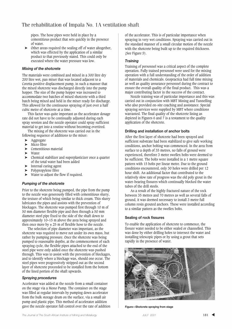
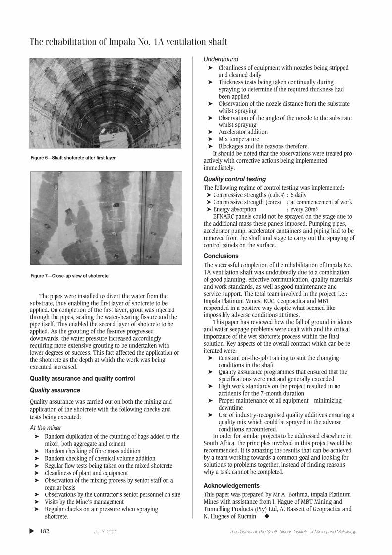
Nozzle training was of particular importance and this wascarried out in conjunction with MBT Mining and Tunnellingwho also provided on-site coaching and assistance. Specialspraying services were supplied by MBT where conditionswarranted. The final quality of the shotcrete lining asdepicted in Figures 6 and 7 is a testament to the qualityapplication of the shotcrete.
Drilling and installation of anchor boltsAfter the first layer of shotcrete had been sprayed andsufficient substrate had been stabilized to give safe workingconditions, anchor bolting was commenced. In the area fromsurface to a depth of 35 metres, no falls of ground wereexperienced, therefore 3 metre swellex bolts were deemed tobe sufficient. The bolts were installed in a 1 metre squarepattern with 15 bolts per linear metre. Due to the groundconditions encountered, only 30 holes were drilled per 12hour shift. An additional factor that contributed to therelatively slow rate of progress was the old poly grout in thewater-bearing fissures which continually blocked the watertubes of the drill steels.
As a result of the highly fractured nature of the rockbetween 35 metres and 70 metres as well as several falls ofground, it was deemed necessary to install 3 metre fullcolumn resin grouted anchors. These were installed accordingto a similar pattern as the swellex bolts.
Sealing of rock fissures
To enable the application of shotcrete to commence, thefissure water needed to be either sealed or channelled. Thiswas done by either drilling holes to intersect the water andinstalling telescopic pipes or by using a grout that setsrapidly in the presence of water.
The rehabilitation of Impala No. 1A ventilation shaft
▲181The Journal of The South African Institute of Mining and Metallurgy JULY 2001
Figure—Shotcrete spraying from stage
The rehabilitation of Impala No. 1A ventilation shaft
The pipes were installed to divert the water from thesubstrate, thus enabling the first layer of shotcrete to beapplied. On completion of the first layer, grout was injectedthrough the pipes, sealing the water-bearing fissure and thepipe itself. This enabled the second layer of shotcrete to beapplied. As the grouting of the fissures progresseddownwards, the water pressure increased accordinglyrequiring more extensive grouting to be undertaken withlower degrees of success. This fact affected the application ofthe shotcrete as the depth at which the work was beingexecuted increased.
Quality assurance and quality control
Quality assurance
Quality assurance was carried out on both the mixing andapplication of the shotcrete with the following checks andtests being executed:
At the mixer➤ Random duplication of the counting of bags added to the
mixer, both aggregate and cement➤ Random checking of fibre mass addition➤ Random checking of chemical volume addition➤ Regular flow tests being taken on the mixed shotcrete➤ Cleanliness of plant and equipment➤ Observation of the mixing process by senior staff on a
regular basis➤ Observations by the Contractor’s senior personnel on site➤ Visits by the Mine’s management➤ Regular checks on air pressure when spraying
shotcrete.
Underground➤ Cleanliness of equipment with nozzles being stripped
and cleaned daily➤ Thickness tests being taken continually during
spraying to determine if the required thickness hadbeen applied
➤ Observation of the nozzle distance from the substratewhilst spraying
➤ Observation of the angle of the nozzle to the substratewhilst spraying
➤ Accelerator addition➤ Mix temperature➤ Blockages and the reasons therefore.
It should be noted that the observations were treated pro-actively with corrective actions being implementedimmediately.
Quality control testingThe following regime of control testing was implemented:
➤ Compressive strengths (cubes) : 6 daily➤ Compressive strength (cores) : at commencement of work➤ Energy absorption : every 20m3
EFNARC panels could not be sprayed on the stage due tothe additional mass these panels imposed. Pumping pipes,accelerator pump, accelerator containers and piping had to beremoved from the shaft and stage to carry out the spraying ofcontrol panels on the surface.
ConclusionsThe successful completion of the rehabilitation of Impala No.1A ventilation shaft was undoubtedly due to a combinationof good planning, effective communication, quality materialsand work standards, as well as good maintenance andservice support. The total team involved in the project, i.e.:Impala Platinum Mines, RUC, Geopractica and MBTresponded in a positive way despite what seemed likeimpossibly adverse conditions at times.
This paper has reviewed how the fall of ground incidentsand water seepage problems were dealt with and the criticalimportance of the wet shotcrete process within the finalsolution. Key aspects of the overall contract which can be re-iterated were:
➤ Constant on-the-job training to suit the changingconditions in the shaft
➤ Quality assurance programmes that ensured that thespecifications were met and generally exceeded
➤ High work standards on the project resulted in noaccidents for the 7-month duration
➤ Proper maintenance of all equipment—minimizingdowntime
➤ Use of industry-recognised quality additives ensuring aquality mix which could be sprayed in the adverseconditions encountered.
In order for similar projects to be addressed elsewhere inSouth Africa, the principles involved in this project would berecommended. It is amazing the results that can be achievedby a team working towards a common goal and looking forsolutions to problems together, instead of finding reasonswhy a task cannot be completed.
AcknowledgementsThis paper was prepared by Mr A. Bothma, Impala PlatinumMines with assistance from I. Hague of MBT Mining andTunnelling Products (Pty) Ltd, A. Bassett of Geopractica andN. Hughes of Rucmin ◆
▲
182 JULY 2001 The Journal of The South African Institute of Mining and Metallurgy
Figure 6—Shaft shotcrete after first layer
Figure 7—Close-up view of shotcrete