Embed Size (px)
Citation preview
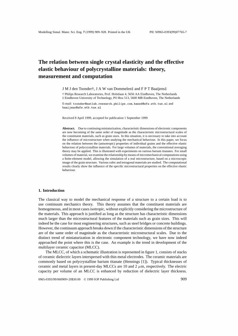
Modelling Simul. Mater. Sci. Eng.7 (1999) 909–928. Printed in the UK PII: S0965-0393(99)07765-7
The relation between single crystal elasticity and the effectiveelastic behaviour of polycrystalline materials: theory,measurement and computation
J M J den Toonder†, J A W vanDommelen‡ and F P TBaaijens‡† Philips Research Laboratories, Prof. Holstlaan 4, 5656 AA Eindhoven, The Netherlands‡ Eindhoven University of Technology, PO Box 513, 5600 MB Eindhoven, The Netherlands
E-mail: [email protected], [email protected] [email protected]
Received 8 April 1999, accepted for publication 1 September 1999
Abstract. Due to continuing miniaturization, characteristic dimensions of electronic componentsare now becoming of the same order of magnitude as the characteristic microstructural scales ofthe constituent materials, such as grain sizes. In this situation, it is necessary to take into accountthe influence of microstructure when studying the mechanical behaviour. In this paper, we focuson the relation between the (anisotropic) properties of individual grains and the effective elasticbehaviour of polycrystalline materials. For large volumes of materials, the conventional averagingtheory may be applied. This is illustrated with experiments on various barium titanates. For smallvolumes of material, we examine the relationship by means of micromechanical computations usinga finite-element model, allowing the simulation of a real microstructure, based on a microscopicimage of the grain structure. Various cubic and tetragonal materials are studied. The computationalresults clearly show the influence of the specific microstructural properties on the effective elasticbehaviour.
1. Introduction
The classical way to model the mechanical response of a structure to a certain load is touse continuum mechanics theory. This theory assumes that the constituent materials arehomogeneous, and in most cases isotropic, without explicitly considering the microstructure ofthe materials. This approach is justified as long as the structure has characteristic dimensionsmuch larger than the microstructural features of the materials such as grain sizes. This willindeed be the case for most engineering structures, such as steel bridges or concrete buildings.However, the continuum approach breaks down if the characteristic dimensions of the structureare of the same order of magnitude as the characteristic microstructural scales. Due to thedistinct trend of miniaturization in electronic component technology, we have now indeedapproached the point where this is the case. An example is the trend in development of themultilayer ceramic capacitor (MLCC).
The MLCC, of which a schematic illustration is represented in figure 1, consists of stacksof ceramic dielectric layers interspersed with thin metal electrodes. The ceramic materials arecommonly based on polycrystalline barium titanate (Hennings [1]). Typical thicknesses ofceramic and metal layers in present-day MLCCs are 10 and 2µm, respectively. The electriccapacity per volume of an MLCC is enhanced by reduction of dielectric layer thickness.
0965-0393/99/060909+20$30.00 © 1999 IOP Publishing Ltd 909
910 J M J den Toonder et al
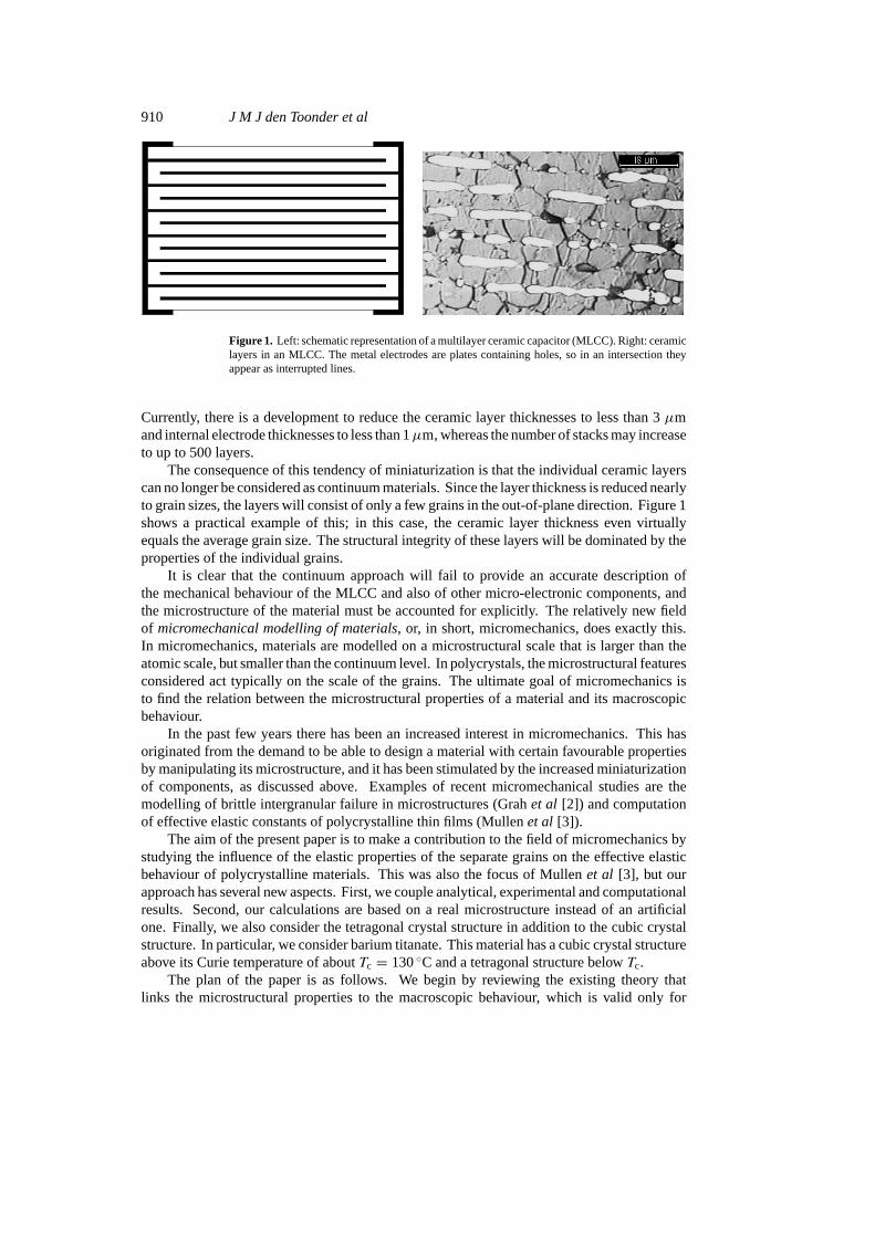
Figure 1. Left: schematic representation of a multilayer ceramic capacitor (MLCC). Right: ceramiclayers in an MLCC. The metal electrodes are plates containing holes, so in an intersection theyappear as interrupted lines.
Currently, there is a development to reduce the ceramic layer thicknesses to less than 3µmand internal electrode thicknesses to less than 1µm, whereas the number of stacks may increaseto up to 500 layers.
The consequence of this tendency of miniaturization is that the individual ceramic layerscan no longer be considered as continuum materials. Since the layer thickness is reduced nearlyto grain sizes, the layers will consist of only a few grains in the out-of-plane direction. Figure 1shows a practical example of this; in this case, the ceramic layer thickness even virtuallyequals the average grain size. The structural integrity of these layers will be dominated by theproperties of the individual grains.
It is clear that the continuum approach will fail to provide an accurate description ofthe mechanical behaviour of the MLCC and also of other micro-electronic components, andthe microstructure of the material must be accounted for explicitly. The relatively new fieldof micromechanical modelling of materials, or, in short, micromechanics, does exactly this.In micromechanics, materials are modelled on a microstructural scale that is larger than theatomic scale, but smaller than the continuum level. In polycrystals, the microstructural featuresconsidered act typically on the scale of the grains. The ultimate goal of micromechanics isto find the relation between the microstructural properties of a material and its macroscopicbehaviour.
In the past few years there has been an increased interest in micromechanics. This hasoriginated from the demand to be able to design a material with certain favourable propertiesby manipulating its microstructure, and it has been stimulated by the increased miniaturizationof components, as discussed above. Examples of recent micromechanical studies are themodelling of brittle intergranular failure in microstructures (Grahet al [2]) and computationof effective elastic constants of polycrystalline thin films (Mullenet al [3]).
The aim of the present paper is to make a contribution to the field of micromechanics bystudying the influence of the elastic properties of the separate grains on the effective elasticbehaviour of polycrystalline materials. This was also the focus of Mullenet al [3], but ourapproach has several new aspects. First, we couple analytical, experimental and computationalresults. Second, our calculations are based on a real microstructure instead of an artificialone. Finally, we also consider the tetragonal crystal structure in addition to the cubic crystalstructure. In particular, we consider barium titanate. This material has a cubic crystal structureabove its Curie temperature of aboutTc = 130◦C and a tetragonal structure belowTc.
The plan of the paper is as follows. We begin by reviewing the existing theory thatlinks the microstructural properties to the macroscopic behaviour, which is valid only for
Single crystal elasticity and effective elastic behaviour 911
large volumes of material. This theory is subsequently illustrated with measurements onvarious barium titanates over a range of temperatures. The last part of the paper is devoted tomicromechanical computational modelling of thin sheets of polycrystalline materials, as arepresent in the MLCCs. The computational results clearly show the influence of the specificmicrostructural properties on the effective elastic behaviour.
2. Macroscopic effective constants of large volumes of polycrystalline materials: theory
A sufficiently large volume of untextured polycrystalline ceramic material can bemacroscopically described as an isotropic elastic material that is characterized by a set of twoindependent material parameters. However, microscopically, the behaviour of the individualgrains will in general be anisotropic. In this section, we will discuss the elastic behaviourof individual cubic and tetragonal crystal structures. Both structures exhibit orthotropicbehaviour. Furthermore, we will give a short review of the theory that links the microscopic,anisotropic properties to the macroscopic, isotropic elastic behaviour.
2.1. Linear isotropic elasticity
Elastic materials are characterized by a direct relation between the local stress state and the localstrain state. In the case of linear elasticity this relation can be represented by the generalizedformulation of Hooke’s law, which states that the stress is proportional to the strain
σ = 4C : E (1)
with σ the Cauchy stress tensor and
E = 12(E∇Eu + ( E∇Eu)T) (2)
the infinitesimal strain tensor, whereEu is the displacement in the material. Equation (1) iscommonly written in a matrix notation. Due to symmetry of the stress tensor and the straintensor only six state variables need to be evaluated. Thus, the stress–strain relation is writtenas (Nye [4], Ting [5])
σ∼ = Cε∼ (3)
with
σ∼T = [ σ11 σ22 σ33 σ23 σ31 σ12 ] (4)
and
ε∼T = [ ε11 ε22 ε33 2ε23 2ε31 2ε12 ]. (5)
For general anisotropic elasticity the elasticity matrixCwill be symmetric and therefore contain21 independent components.
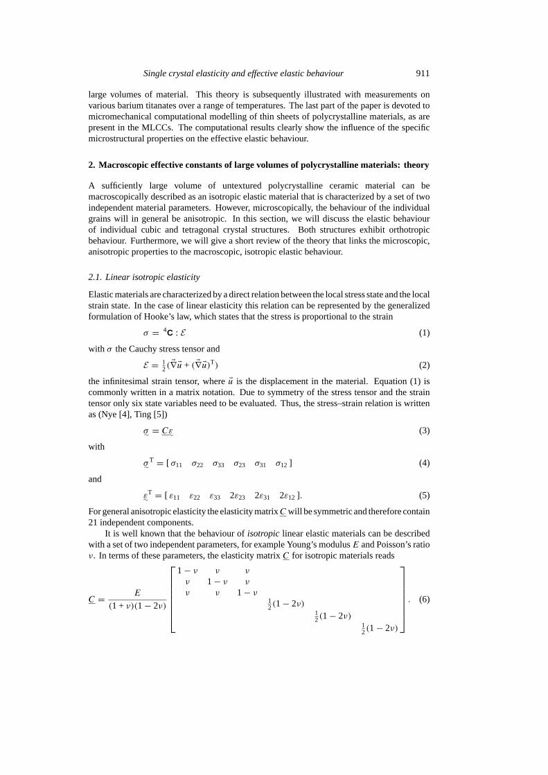
It is well known that the behaviour ofisotropic linear elastic materials can be describedwith a set of two independent parameters, for example Young’s modulusE and Poisson’s ratioν. In terms of these parameters, the elasticity matrixC for isotropic materials reads
C = E
(1 + ν)(1− 2ν)
1− ν ν ν
ν 1− ν ν
ν ν 1− ν12(1− 2ν)
12(1− 2ν)
12(1− 2ν)
. (6)
912 J M J den Toonder et al
Alternatively, isotropic linear elastic behaviour can also be characterized with the shearmodulusG in combination with the bulk modulusκ. The sets of material parameters(E, ν)and(G, κ) are related as
G = E
2(1 + ν)κ = E
3(1− 2ν). (7)
2.2. Crystal elasticity
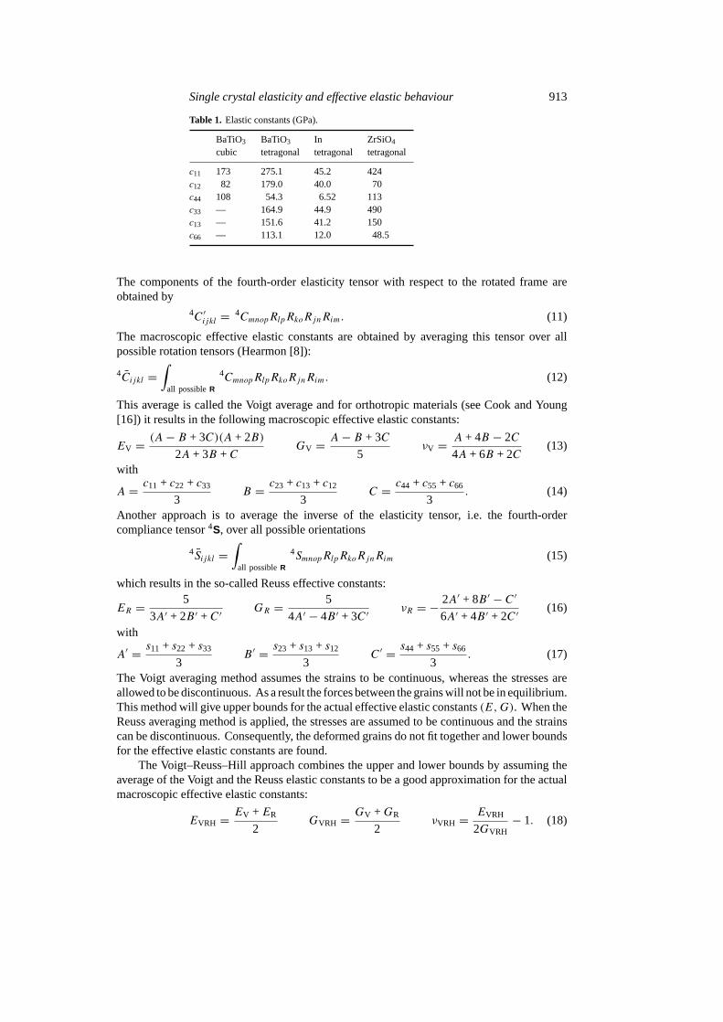
Single-crystal elasticity will in general not be isotropic. The number of independent materialparameters depends on the level of symmetry of the crystal structure. For the cubic structure,the elasticity matrix can be written in terms of three independent material parameters (Nye [4],Ting [5]):
C =
c11 c12 c12
c12 c11 c12
c12 c12 c11
c44
c44
c44
. (8)
If the relation 2c44 = c11 − c12 is satisfied, the material will be isotropic and the elasticitymatrix can be written in the form of equation (6).
Tetragonal crystal structures have lower symmetry properties. As a result, for a completedescription of the constitutive behaviour six independent parameters are needed:
C =
c11 c12 c13
c12 c11 c13
c13 c13 c33
c44
c44
c66
. (9)
In this study, we are particularly interested in barium titanate (BaTiO3) at varioustemperatures. At temperatures above approximately 130◦C, which is the Curie temperaturefor this material, the barium titanate crystals have a cubic structure. At lower temperaturesthe crystal structure is tetragonal. In addition to barium titanate, we consider two moreceramic materials, namely indium (In) and zircon (ZrSiO4). In table 1 the various independentcomponents of the elasticity matrix are given for the materials investigated (Hellwege [6],Berlincourt and Jaffe [7]).
2.3. Effective elastic constants
Generally a ceramic material will consist of a number of grains, each with a different andunique orientation with respect to a reference frame. All individual grains will microscopicallyshow anisotropic material behaviour that is dependent on the crystal structure and orientation.However, when the number of grains is sufficiently large and the orientations are randomlydistributed, the effective macroscopic behaviour will be isotropic and the constitutive propertiescan be characterized by an effective Young’s modulus and an effective Poisson’s ratio.
The macroscopic effective elastic constants are found by averaging the anisotropic elasticproperties of the individual crystals over all possible crystal orientations. To this end a rotationtensor between a reference frame and a rotated vector basis attached to the crystal structure isdefined:
Ee∼′ = R · Ee∼ with R · RT = I. (10)
Single crystal elasticity and effective elastic behaviour 913
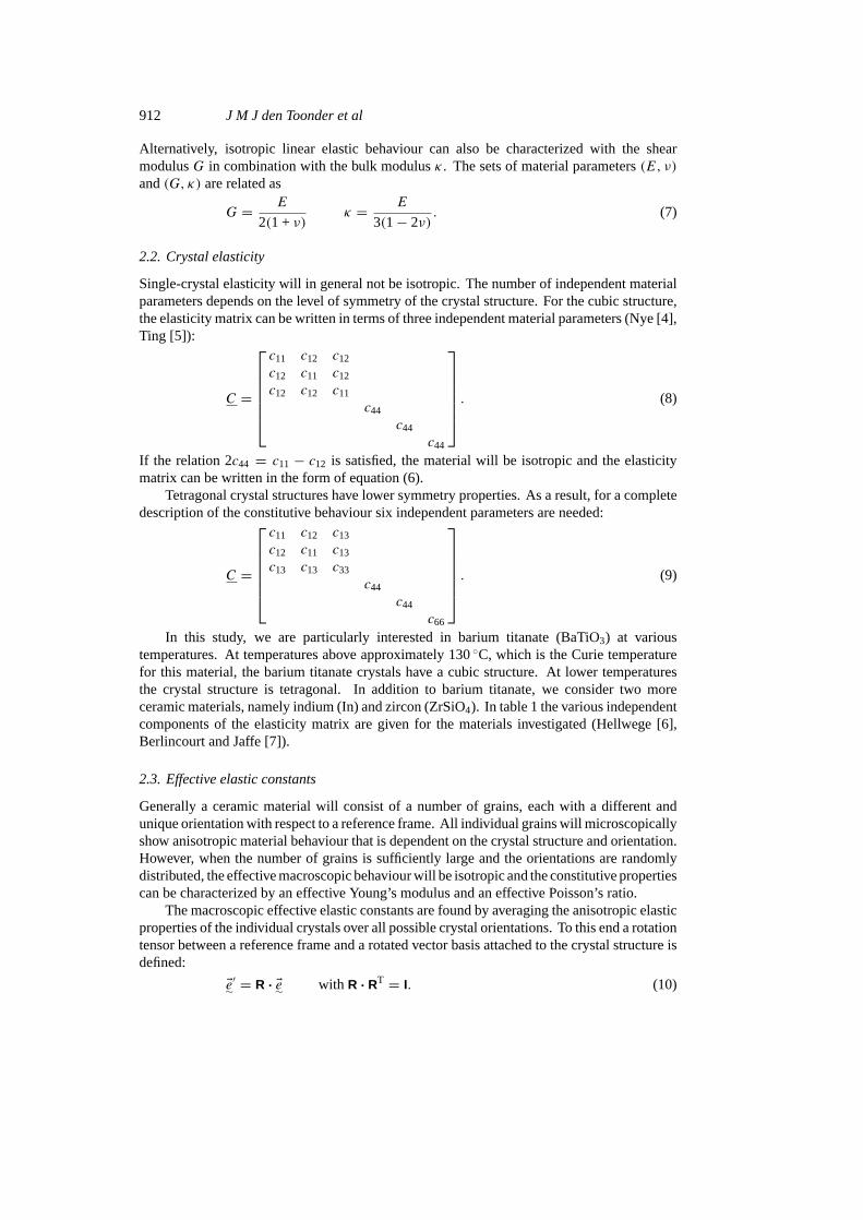
Table 1. Elastic constants (GPa).
BaTiO3 BaTiO3 In ZrSiO4
cubic tetragonal tetragonal tetragonal
c11 173 275.1 45.2 424c12 82 179.0 40.0 70c44 108 54.3 6.52 113c33 — 164.9 44.9 490c13 — 151.6 41.2 150c66 — 113.1 12.0 48.5
The components of the fourth-order elasticity tensor with respect to the rotated frame areobtained by
4C ′ijkl = 4CmnopRlpRkoRjnRim. (11)
The macroscopic effective elastic constants are obtained by averaging this tensor over allpossible rotation tensors (Hearmon [8]):
4Cijkl =∫
all possibleR
4CmnopRlpRkoRjnRim. (12)
This average is called the Voigt average and for orthotropic materials (see Cook and Young[16]) it results in the following macroscopic effective elastic constants:
EV = (A− B + 3C)(A + 2B)
2A + 3B +CGV = A− B + 3C
5νV = A + 4B − 2C
4A + 6B + 2C(13)
with
A = c11 + c22 + c33
3B = c23 + c13 + c12
3C = c44 + c55 + c66
3. (14)
Another approach is to average the inverse of the elasticity tensor, i.e. the fourth-ordercompliance tensor4S, over all possible orientations
4Sijkl =∫
all possibleR
4SmnopRlpRkoRjnRim (15)
which results in the so-called Reuss effective constants:
ER = 5
3A′ + 2B ′ +C ′GR = 5
4A′ − 4B ′ + 3C ′νR = − 2A′ + 8B ′ − C ′
6A′ + 4B ′ + 2C ′(16)
with
A′ = s11 + s22 + s33
3B ′ = s23 + s13 + s12
3C ′ = s44 + s55 + s66
3. (17)
The Voigt averaging method assumes the strains to be continuous, whereas the stresses areallowed to be discontinuous. As a result the forces between the grains will not be in equilibrium.This method will give upper bounds for the actual effective elastic constants(E,G). When theReuss averaging method is applied, the stresses are assumed to be continuous and the strainscan be discontinuous. Consequently, the deformed grains do not fit together and lower boundsfor the effective elastic constants are found.
The Voigt–Reuss–Hill approach combines the upper and lower bounds by assuming theaverage of the Voigt and the Reuss elastic constants to be a good approximation for the actualmacroscopic effective elastic constants:
EVRH = EV +ER
2GVRH = GV +GR
2νVRH = EVRH
2GVRH− 1. (18)
914 J M J den Toonder et al
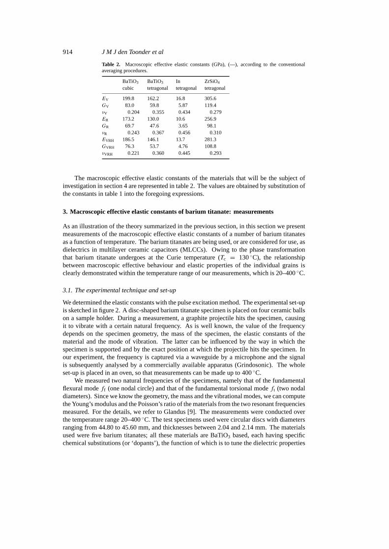
Table 2. Macroscopic effective elastic constants (GPa), (—), according to the conventionalaveraging procedures.
BaTiO3 BaTiO3 In ZrSiO4
cubic tetragonal tetragonal tetragonal
EV 199.8 162.2 16.8 305.6GV 83.0 59.8 5.87 119.4νV 0.204 0.355 0.434 0.279ER 173.2 130.0 10.6 256.9GR 69.7 47.6 3.65 98.1νR 0.243 0.367 0.456 0.310EVRH 186.5 146.1 13.7 281.3GVRH 76.3 53.7 4.76 108.8νVRH 0.221 0.360 0.445 0.293
The macroscopic effective elastic constants of the materials that will be the subject ofinvestigation in section 4 are represented in table 2. The values are obtained by substitution ofthe constants in table 1 into the foregoing expressions.
3. Macroscopic effective elastic constants of barium titanate: measurements
As an illustration of the theory summarized in the previous section, in this section we presentmeasurements of the macroscopic effective elastic constants of a number of barium titanatesas a function of temperature. The barium titanates are being used, or are considered for use, asdielectrics in multilayer ceramic capacitors (MLCCs). Owing to the phase transformationthat barium titanate undergoes at the Curie temperature (Tc = 130◦C), the relationshipbetween macroscopic effective behaviour and elastic properties of the individual grains isclearly demonstrated within the temperature range of our measurements, which is 20–400◦C.
3.1. The experimental technique and set-up
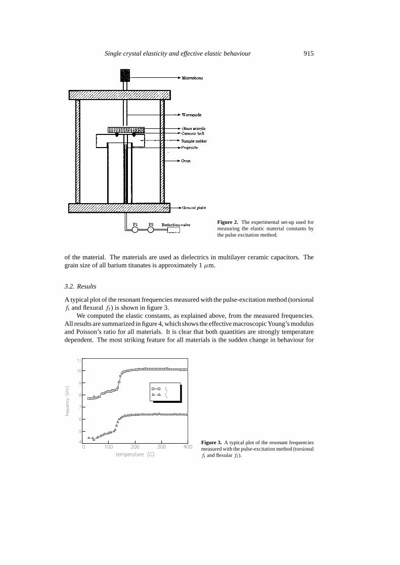
We determined the elastic constants with the pulse excitation method. The experimental set-upis sketched in figure 2. A disc-shaped barium titanate specimen is placed on four ceramic ballson a sample holder. During a measurement, a graphite projectile hits the specimen, causingit to vibrate with a certain natural frequency. As is well known, the value of the frequencydepends on the specimen geometry, the mass of the specimen, the elastic constants of thematerial and the mode of vibration. The latter can be influenced by the way in which thespecimen is supported and by the exact position at which the projectile hits the specimen. Inour experiment, the frequency is captured via a waveguide by a microphone and the signalis subsequently analysed by a commercially available apparatus (Grindosonic). The wholeset-up is placed in an oven, so that measurements can be made up to 400◦C.
We measured two natural frequencies of the specimens, namely that of the fundamentalflexural modeff (one nodal circle) and that of the fundamental torsional modeft (two nodaldiameters). Since we know the geometry, the mass and the vibrational modes, we can computethe Young’s modulus and the Poisson’s ratio of the materials from the two resonant frequenciesmeasured. For the details, we refer to Glandus [9]. The measurements were conducted overthe temperature range 20–400◦C. The test specimens used were circular discs with diametersranging from 44.80 to 45.60 mm, and thicknesses between 2.04 and 2.14 mm. The materialsused were five barium titanates; all these materials are BaTiO3 based, each having specificchemical substitutions (or ‘dopants’), the function of which is to tune the dielectric properties
Single crystal elasticity and effective elastic behaviour 915
Figure 2. The experimental set-up used formeasuring the elastic material constants bythe pulse excitation method.
of the material. The materials are used as dielectrics in multilayer ceramic capacitors. Thegrain size of all barium titanates is approximately 1µm.
3.2. Results
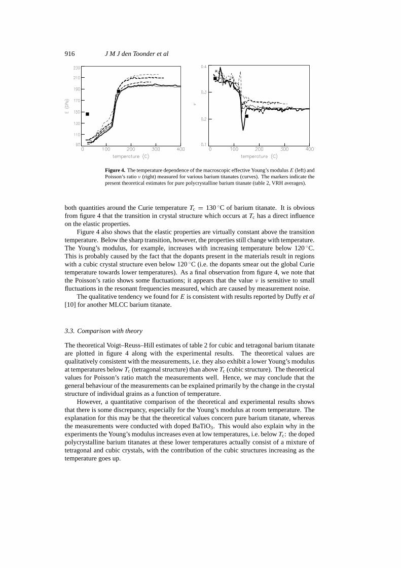
A typical plot of the resonant frequencies measured with the pulse-excitation method (torsionalft and flexuralff ) is shown in figure 3.
We computed the elastic constants, as explained above, from the measured frequencies.All results are summarized in figure 4, which shows the effective macroscopic Young’s modulusand Poisson’s ratio for all materials. It is clear that both quantities are strongly temperaturedependent. The most striking feature for all materials is the sudden change in behaviour for
Figure 3. A typical plot of the resonant frequenciesmeasured with the pulse-excitation method (torsionalft and flexularff ).
916 J M J den Toonder et al
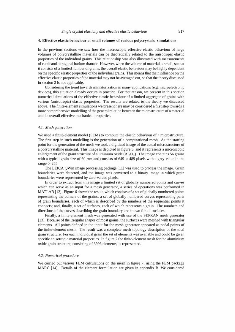
Figure 4. The temperature dependence of the macroscopic effective Young’s modulusE (left) andPoisson’s ratioν (right) measured for various barium titanates (curves). The markers indicate thepresent theoretical estimates for pure polycrystalline barium titanate (table 2, VRH averages).
both quantities around the Curie temperatureTc = 130◦C of barium titanate. It is obviousfrom figure 4 that the transition in crystal structure which occurs atTc has a direct influenceon the elastic properties.
Figure 4 also shows that the elastic properties are virtually constant above the transitiontemperature. Below the sharp transition, however, the properties still change with temperature.The Young’s modulus, for example, increases with increasing temperature below 120◦C.This is probably caused by the fact that the dopants present in the materials result in regionswith a cubic crystal structure even below 120◦C (i.e. the dopants smear out the global Curietemperature towards lower temperatures). As a final observation from figure 4, we note thatthe Poisson’s ratio shows some fluctuations; it appears that the valueν is sensitive to smallfluctuations in the resonant frequencies measured, which are caused by measurement noise.
The qualitative tendency we found forE is consistent with results reported by Duffyet al[10] for another MLCC barium titanate.
3.3. Comparison with theory
The theoretical Voigt–Reuss–Hill estimates of table 2 for cubic and tetragonal barium titanateare plotted in figure 4 along with the experimental results. The theoretical values arequalitatively consistent with the measurements, i.e. they also exhibit a lower Young’s modulusat temperatures belowTc (tetragonal structure) than aboveTc (cubic structure). The theoreticalvalues for Poisson’s ratio match the measurements well. Hence, we may conclude that thegeneral behaviour of the measurements can be explained primarily by the change in the crystalstructure of individual grains as a function of temperature.
However, a quantitative comparison of the theoretical and experimental results showsthat there is some discrepancy, especially for the Young’s modulus at room temperature. Theexplanation for this may be that the theoretical values concern pure barium titanate, whereasthe measurements were conducted with doped BaTiO3. This would also explain why in theexperiments the Young’s modulus increases even at low temperatures, i.e. belowTc: the dopedpolycrystalline barium titanates at these lower temperatures actually consist of a mixture oftetragonal and cubic crystals, with the contribution of the cubic structures increasing as thetemperature goes up.
Single crystal elasticity and effective elastic behaviour 917
4. Effective elastic behaviour of small volumes of various polycrystals: simulations
In the previous sections we saw how the macroscopic effective elastic behaviour of largevolumes of polycrystalline materials can be theoretically related to the anisotropic elasticproperties of the individual grains. This relationship was also illustrated with measurementsof cubic and tetragonal barium titanate. However, when the volume of material is small, so thatit consists of a limited number of grains, the overall elastic behaviour may be highly dependenton the specific elastic properties of the individual grains. This means that their influence on theeffective elastic properties of the material may not be averaged out, so that the theory discussedin section 2 is not applicable.
Considering the trend towards miniaturization in many applications (e.g. microelectronicdevices), this situation already occurs in practice. For that reason, we present in this sectionnumerical simulations of the effective elastic behaviour of a limited aggregate of grains withvarious (anisotropic) elastic properties. The results are related to the theory we discussedabove. The finite-element simulations we present here may be considered a first step towards amore comprehensive modelling of the general relation between the microstructure of a materialand its overall effective mechanical properties.
4.1. Mesh generation
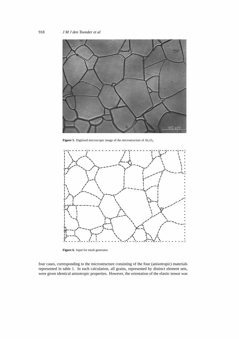
We used a finite-element model (FEM) to compute the elastic behaviour of a microstructure.The first step in such modelling is the generation of a computational mesh. As the startingpoint for the generation of the mesh we took a digitized image of the actual microstructure ofa polycrystalline material. This image is depicted in figure 5, and it represents a microscopicenlargement of the grain structure of aluminium oxide (Al2O3). The image contains 56 grainswith a typical grain size of 60µm and consists of 649× 489 pixels with a grey-value in therange 0–255.
The LEICA QWin image processing package [11] was used to process the image. Grainboundaries were detected, and the image was converted to a binary image in which grainboundaries were represented by zero-valued pixels.
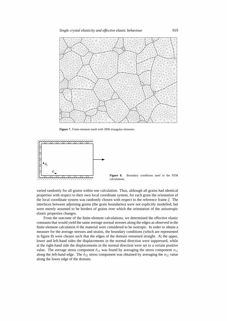
In order to extract from this image a limited set of globally numbered points and curveswhich can serve as an input for a mesh generator, a series of operations was performed inMATLAB [12]. Figure 6 shows the result, which consists of a set of globally numbered pointsrepresenting the corners of the grains; a set of globally numbered curves representing partsof grain boundaries, each of which is described by the numbers of the sequential points itconnects; and, finally, a set of surfaces, each of which represents a grain. The numbers anddirections of the curves describing the grain boundary are known for all surfaces.
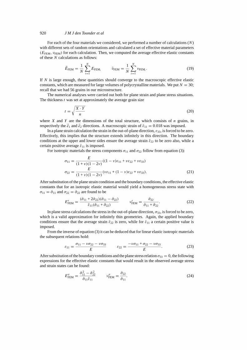
Finally, a finite-element mesh was generated with use of the SEPRAN mesh generator[13]. Because of the irregular shapes of most grains, the surfaces were meshed with triangularelements. All points defined in the input for the mesh generator appeared as nodal points ofthe finite-element mesh. The result was a complete mesh topology description of the totalgrain structure. For each individual grain the set of elements was available and could be givenspecific anisotropic material properties. In figure 7 the finite-element mesh for the aluminiumoxide grain structure, consisting of 3996 elements, is represented.
4.2. Numerical procedure
We carried out various FEM calculations on the mesh in figure 7, using the FEM packageMARC [14]. Details of the element formulation are given in appendix B. We considered
918 J M J den Toonder et al
Figure 5. Digitized microscopic image of the microstructure of Al2O3.
Figure 6. Input for mesh generator.
four cases, corresponding to the microstructure consisting of the four (anisotropic) materialsrepresented in table 1. In each calculation, all grains, represented by distinct element sets,were given identical anisotropic properties. However, the orientation of the elastic tensor was
Single crystal elasticity and effective elastic behaviour 919
Figure 7. Finite-element mesh with 3996 triangular elements.
Figure 8. Boundary conditions used in the FEMcalculations.
varied randomly for all grains within one calculation. Thus, although all grains had identicalproperties with respect to their own local coordinate system, for each grain the orientation ofthe local coordinate system was randomly chosen with respect to the reference frameEe∼. Theinterfaces between adjoining grains (the grain boundaries) were not explicitly modelled, butwere merely assumed to be borders of grains over which the orientation of the anisotropicelastic properties changes.
From the outcome of the finite-element calculations, we determined the effective elasticconstants that would yield the same average normal stresses along the edges as observed in thefinite-element calculation if the material were considered to be isotropic. In order to obtain ameasure for the average stresses and strains, the boundary conditions (which are representedin figure 8) were chosen such that the edges of the domain remained straight. At the upper,lower and left-hand sides the displacements in the normal direction were suppressed, whileat the right-hand side the displacements in the normal direction were set to a certain positivevalue. The average stress componentσ11 was found by averaging the stress componentσ11
along the left-hand edge. Theσ22 stress component was obtained by averaging theσ22 valuealong the lower edge of the domain.
920 J M J den Toonder et al
For each of the four materials we considered, we performed a number of calculations (N )with different sets of random orientations and calculated a set of effective material parameters(EFEM, νFEM) for each calculation. Then, we computed the average effective elastic constantsof theseN calculations as follows:
EFEM = 1
N
N∑i=1
EFEMiνFEM = 1
N
N∑i=1
νFEMi. (19)
If N is large enough, these quantities should converge to the macroscopic effective elasticconstants, which are measured for large volumes of polycrystalline materials. We putN = 30;recall that we had 56 grains in our microstructure.
The numerical analyses were carried out both for plane strain and plane stress situations.The thicknesst was set at approximately the average grain size
t =√X · Yn
(20)
whereX and Y are the dimensions of the total structure, which consists ofn grains, inrespectively theEe1 andEe2 directions. A macroscopic strain ofε11 = 0.018 was imposed.
In a plane strain calculation the strain in the out-of-plane direction,ε33, is forced to be zero.Effectively, this implies that the structure extends infinitely in this direction. The boundaryconditions at the upper and lower sides ensure the average strainε22 to be zero also, while acertain positive averageε11 is imposed.
For isotropic materials the stress componentsσ11 andσ22 follow from equation (3):
σ11 = E
(1 + ν)(1− 2ν)((1− ν)ε11 + νε22 + νε33)
σ22 = E
(1 + ν)(1− 2ν)(νε11 + (1− ν)ε22 + νε33). (21)
After substitution of the plane strain condition and the boundary conditions, the effective elasticconstants that for an isotropic elastic material would yield a homogeneous stress state withσ11 = σ11 andσ22 = σ22 are found to be
EεFEM =(σ11 + 2σ22)(σ11− σ22)
ε11(σ11 + σ22)νεFEM =
σ22
σ11 + σ22. (22)
In plane stress calculations the stress in the out-of-plane direction,σ33, is forced to be zero,which is a valid approximation for infinitely thin geometries. Again, the applied boundaryconditions ensure that the average strainε22 is zero, while forε11 a certain positive value isimposed.
From the inverse of equation (3) it can be deduced that for linear elastic isotropic materialsthe subsequent relations hold:
ε11 = σ11− νσ22− νσ33
Eε22 = −νσ11 + σ22− νσ33
E. (23)
After substitution of the boundary conditions and the plane stress relationσ33 = 0, the followingexpressions for the effective elastic constants that would result in the observed average stressand strain states can be found:
EσFEM =σ 2
11− σ 222
σ11ε11νσFEM =
σ22
σ11. (24)
Single crystal elasticity and effective elastic behaviour 921
Table 3. Plane strain FEM average effective elastic constants (GPa), (—).
BaTiO3 BaTiO3 In ZrSiO4
cubic tetragonal tetragonal tetragonal
EεFEM 186.6 162.8 15.7 279.9std(EεFEM) 7.1 12.0 1.2 14.4νεFEM 0.223 0.355 0.438 0.292std(νεFEM) 0.012 0.009 0.005 0.012
0
50
100
150
200
250
300
Effe
ctiv
e Y
oung
’s m
odul
us [G
Pa]
Voigt Reuss Voigt−Reuss−HillFEM
0
0.05
0.1
0.15
0.2
0.25
0.3
0.35
0.4
0.45
0.5
Effe
ctiv
e P
oiss
on’s
rat
io [−
]
Voigt Reuss Voigt−Reuss−HillFEM
0
50
100
150
200
250
300
Effe
ctiv
e Y
oung
’s m
odul
us [G
Pa]
Voigt Reuss Voigt−Reuss−HillFEM
0
0.05
0.1
0.15
0.2
0.25
0.3
0.35
0.4
0.45
0.5
Effe
ctiv
e P
oiss
on’s
rat
io [−
]
Voigt Reuss Voigt−Reuss−HillFEM
Figure 9. Plane strain effective constants: barium titanate, cubic (top); barium titanate,tetragonal (bottom).
4.3. Results
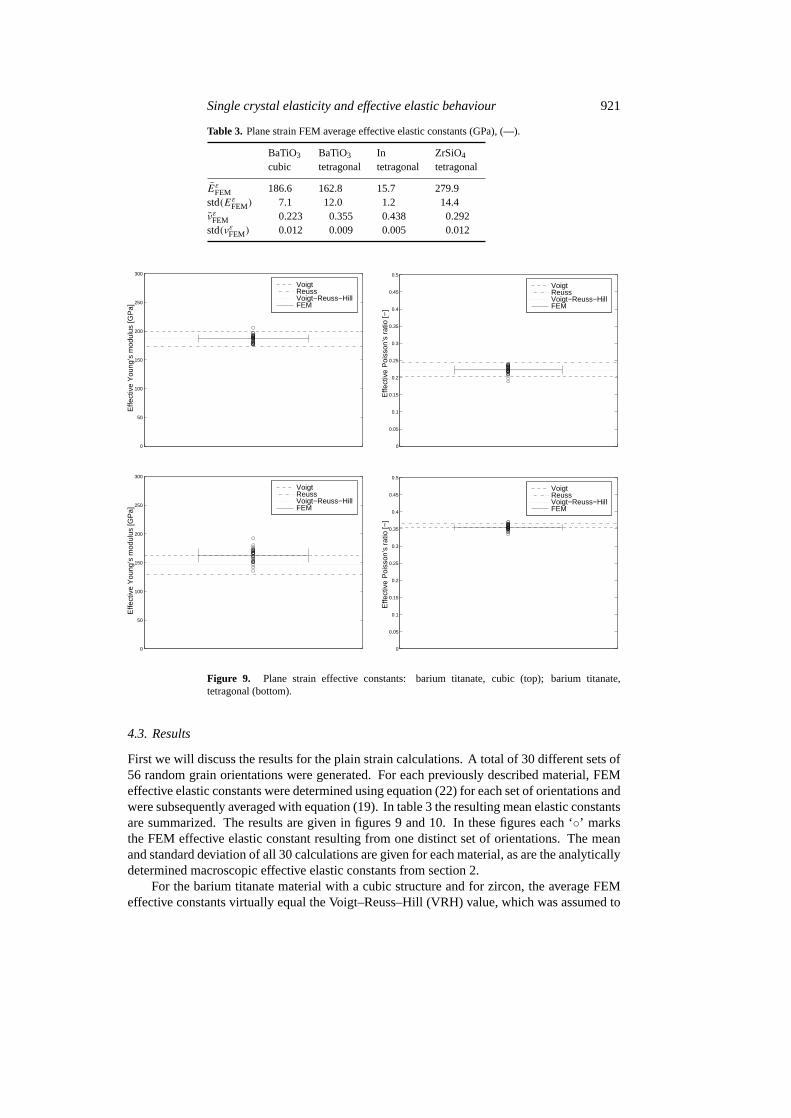
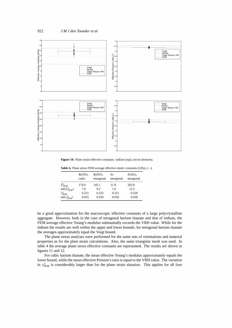
First we will discuss the results for the plain strain calculations. A total of 30 different sets of56 random grain orientations were generated. For each previously described material, FEMeffective elastic constants were determined using equation (22) for each set of orientations andwere subsequently averaged with equation (19). In table 3 the resulting mean elastic constantsare summarized. The results are given in figures 9 and 10. In these figures each ‘◦’ marksthe FEM effective elastic constant resulting from one distinct set of orientations. The meanand standard deviation of all 30 calculations are given for each material, as are the analyticallydetermined macroscopic effective elastic constants from section 2.
For the barium titanate material with a cubic structure and for zircon, the average FEMeffective constants virtually equal the Voigt–Reuss–Hill (VRH) value, which was assumed to
922 J M J den Toonder et al
0
2
4
6
8
10
12
14
16
18
20
Effe
ctiv
e Y
oung
’s m
odul
us [G
Pa]
Voigt Reuss Voigt−Reuss−HillFEM
0
0.05
0.1
0.15
0.2
0.25
0.3
0.35
0.4
0.45
0.5
Effe
ctiv
e P
oiss
on’s
rat
io [−
]
Voigt Reuss Voigt−Reuss−HillFEM
0
50
100
150
200
250
300
350
400
Effe
ctiv
e Y
oung
’s m
odul
us [G
Pa]
Voigt Reuss Voigt−Reuss−HillFEM
0
0.05
0.1
0.15
0.2
0.25
0.3
0.35
0.4
0.45
0.5
Effe
ctiv
e P
oiss
on’s
rat
io [−
]
Voigt Reuss Voigt−Reuss−HillFEM
Figure 10. Plane strain effective constants: indium (top); zircon (bottom).
Table 4. Plane stress FEM average effective elastic constants (GPa), (—).
BaTiO3 BaTiO3 In ZrSiO4
cubic tetragonal tetragonal tetragonal
EσFEM 174.0 145.1 11.8 263.8std(EσFEM) 7.0 9.2 1.0 13.2νσFEM 0.221 0.322 0.351 0.320std(νσFEM) 0.025 0.030 0.056 0.030
be a good approximation for the macroscopic effective constants of a large polycrystallineaggregate. However, both in the case of tetragonal barium titanate and that of indium, theFEM average effective Young’s modulus substantially exceeds the VRH value. While for theindium the results are well within the upper and lower bounds, for tetragonal barium titanatethe averages approximately equal the Voigt bound.
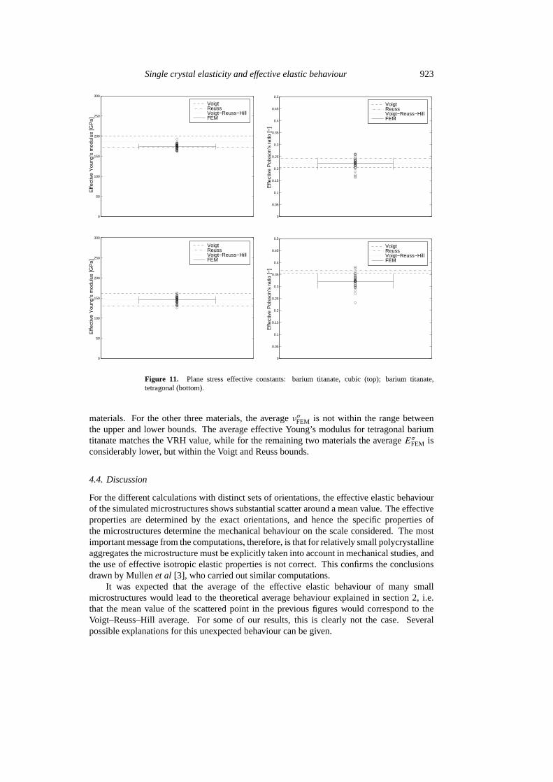
The plane stress analyses were performed for the same sets of orientations and materialproperties as for the plain strain calculations. Also, the same triangular mesh was used. Intable 4 the average plane stress effective constants are represented. The results are shown infigures 11 and 12.
For cubic barium titanate, the mean effective Young’s modulus approximately equals thelower bound, while the mean effective Poisson’s ratio is equal to the VRH value. The variationin νσFEM is considerably larger than for the plane strain situation. This applies for all four
Single crystal elasticity and effective elastic behaviour 923
0
50
100
150
200
250
300
Effe
ctiv
e Y
oung
’s m
odul
us [G
Pa]
Voigt Reuss Voigt−Reuss−HillFEM
0
0.05
0.1
0.15
0.2
0.25
0.3
0.35
0.4
0.45
0.5
Effe
ctiv
e P
oiss
on’s
rat
io [−
]
Voigt Reuss Voigt−Reuss−HillFEM
0
50
100
150
200
250
300
Effe
ctiv
e Y
oung
’s m
odul
us [G
Pa]
Voigt Reuss Voigt−Reuss−HillFEM
0
0.05
0.1
0.15
0.2
0.25
0.3
0.35
0.4
0.45
0.5
Effe
ctiv
e P
oiss
on’s
rat
io [−
]
Voigt Reuss Voigt−Reuss−HillFEM
Figure 11. Plane stress effective constants: barium titanate, cubic (top); barium titanate,tetragonal (bottom).
materials. For the other three materials, the averageνσFEM is not within the range betweenthe upper and lower bounds. The average effective Young’s modulus for tetragonal bariumtitanate matches the VRH value, while for the remaining two materials the averageEσFEM isconsiderably lower, but within the Voigt and Reuss bounds.
4.4. Discussion
For the different calculations with distinct sets of orientations, the effective elastic behaviourof the simulated microstructures shows substantial scatter around a mean value. The effectiveproperties are determined by the exact orientations, and hence the specific properties ofthe microstructures determine the mechanical behaviour on the scale considered. The mostimportant message from the computations, therefore, is that for relatively small polycrystallineaggregates the microstructure must be explicitly taken into account in mechanical studies, andthe use of effective isotropic elastic properties is not correct. This confirms the conclusionsdrawn by Mullenet al [3], who carried out similar computations.
It was expected that the average of the effective elastic behaviour of many smallmicrostructures would lead to the theoretical average behaviour explained in section 2, i.e.that the mean value of the scattered point in the previous figures would correspond to theVoigt–Reuss–Hill average. For some of our results, this is clearly not the case. Severalpossible explanations for this unexpected behaviour can be given.
924 J M J den Toonder et al
0
2
4
6
8
10
12
14
16
18
20E
ffect
ive
You
ng’s
mod
ulus
[GP
a]
Voigt Reuss Voigt−Reuss−HillFEM
0
0.05
0.1
0.15
0.2
0.25
0.3
0.35
0.4
0.45
0.5
Effe
ctiv
e P
oiss
on’s
rat
io [−
]
Voigt Reuss Voigt−Reuss−HillFEM
0
50
100
150
200
250
300
350
400
Effe
ctiv
e Y
oung
’s m
odul
us [G
Pa]
Voigt Reuss Voigt−Reuss−HillFEM
0
0.05
0.1
0.15
0.2
0.25
0.3
0.35
0.4
0.45
0.5
Effe
ctiv
e P
oiss
on’s
rat
io [−
]
Voigt Reuss Voigt−Reuss−HillFEM
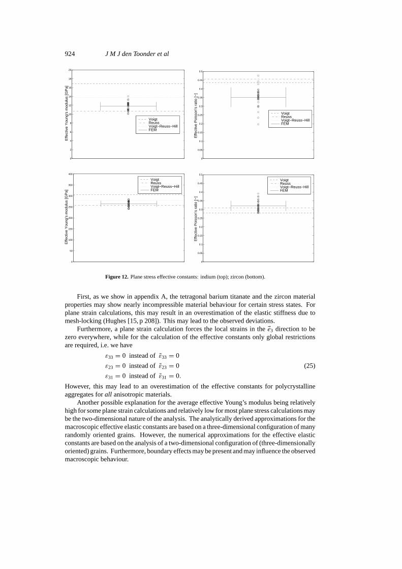
Figure 12. Plane stress effective constants: indium (top); zircon (bottom).
First, as we show in appendix A, the tetragonal barium titanate and the zircon materialproperties may show nearly incompressible material behaviour for certain stress states. Forplane strain calculations, this may result in an overestimation of the elastic stiffness due tomesh-locking (Hughes [15, p 208]). This may lead to the observed deviations.
Furthermore, a plane strain calculation forces the local strains in theEe3 direction to bezero everywhere, while for the calculation of the effective constants only global restrictionsare required, i.e. we have
ε33 = 0 instead ofε33 = 0
ε23 = 0 instead ofε23 = 0 (25)
ε31 = 0 instead ofε31 = 0.
However, this may lead to an overestimation of the effective constants for polycrystallineaggregates forall anisotropic materials.
Another possible explanation for the average effective Young’s modulus being relativelyhigh for some plane strain calculations and relatively low for most plane stress calculations maybe the two-dimensional nature of the analysis. The analytically derived approximations for themacroscopic effective elastic constants are based on a three-dimensional configuration of manyrandomly oriented grains. However, the numerical approximations for the effective elasticconstants are based on the analysis of a two-dimensional configuration of (three-dimensionallyoriented) grains. Furthermore, boundary effects may be present and may influence the observedmacroscopic behaviour.
Single crystal elasticity and effective elastic behaviour 925
Table 5. Influence of mesh refinement. Computed effective elastic constants for one set oforientations in the case of tetragonal barium titanate.
Number ofelements EεFEM (GPa) νεFEM (—)
1 066 156.4 0.3591 759 154.3 0.3603 996 152.4 0.3626 025 151.1 0.363
11 303 152.3 0.36233 268 151.4 0.362
0
50
100
150
200
250
300
Effe
ctiv
e Y
oung
’s m
odul
us [G
Pa]
Voigt Reuss Voigt−Reuss−HillFEM
0
0.05
0.1
0.15
0.2
0.25
0.3
0.35
0.4
0.45
0.5
Effe
ctiv
e P
oiss
on’s
rat
io [−
]
Voigt Reuss Voigt−Reuss−HillFEM
Figure 13. Plane strain effective constants with quadrilateral elements: barium titanate, tetragonal.
Other errors might be influenced by the nature of the computational mesh and the elementformulation, which should always be considered when performing finite-element modelling.Details of the element formulations used are given in appendix B.
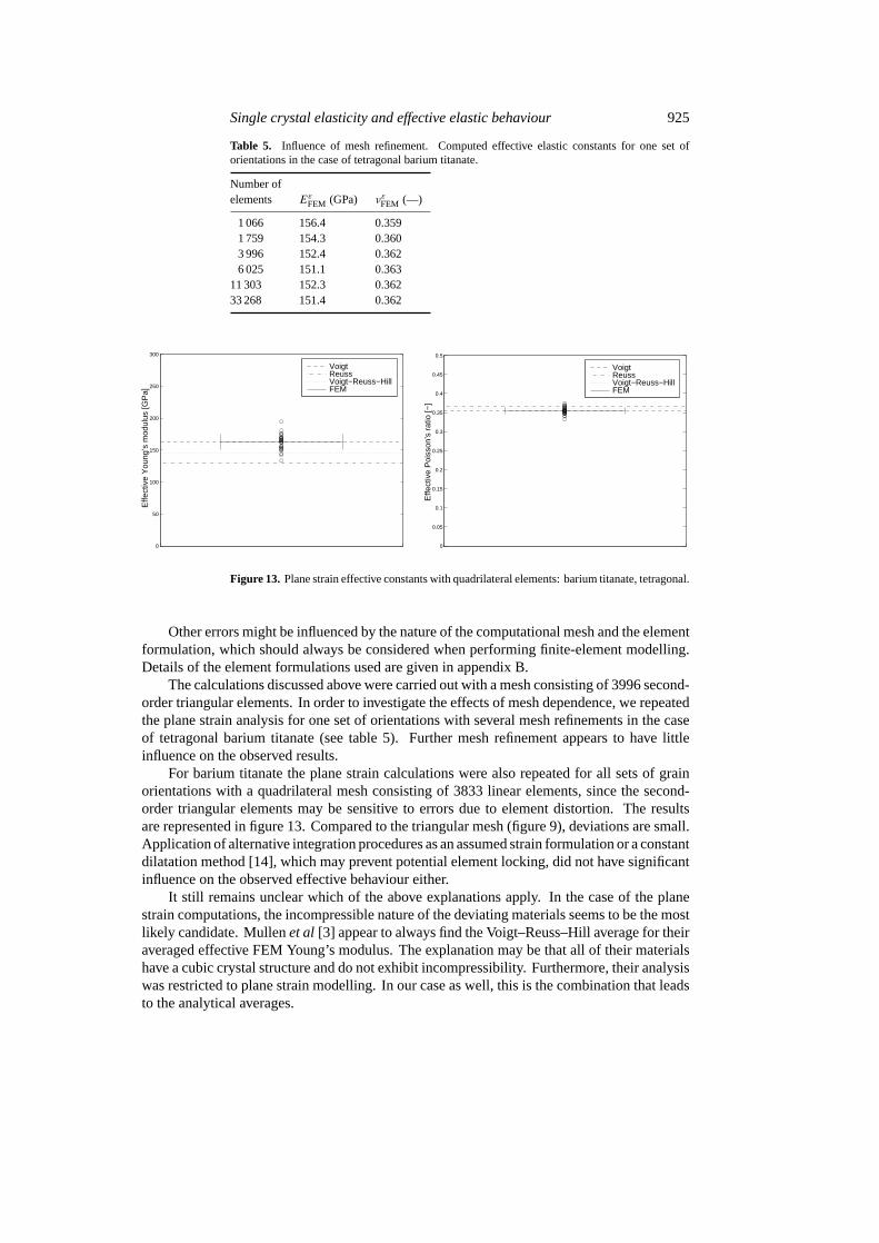
The calculations discussed above were carried out with a mesh consisting of 3996 second-order triangular elements. In order to investigate the effects of mesh dependence, we repeatedthe plane strain analysis for one set of orientations with several mesh refinements in the caseof tetragonal barium titanate (see table 5). Further mesh refinement appears to have littleinfluence on the observed results.
For barium titanate the plane strain calculations were also repeated for all sets of grainorientations with a quadrilateral mesh consisting of 3833 linear elements, since the second-order triangular elements may be sensitive to errors due to element distortion. The resultsare represented in figure 13. Compared to the triangular mesh (figure 9), deviations are small.Application of alternative integration procedures as an assumed strain formulation or a constantdilatation method [14], which may prevent potential element locking, did not have significantinfluence on the observed effective behaviour either.
It still remains unclear which of the above explanations apply. In the case of the planestrain computations, the incompressible nature of the deviating materials seems to be the mostlikely candidate. Mullenet al [3] appear to always find the Voigt–Reuss–Hill average for theiraveraged effective FEM Young’s modulus. The explanation may be that all of their materialshave a cubic crystal structure and do not exhibit incompressibility. Furthermore, their analysiswas restricted to plane strain modelling. In our case as well, this is the combination that leadsto the analytical averages.
926 J M J den Toonder et al
5. Conclusions
In this paper we examined the relation between the (anisotropic) properties of the individualgrains and the effective macroscopic elastic behaviour of polycrystalline materials. For largevolumes of material, the conventional analytical theory of averaging the crystal properties canbe used to establish this relationship. We illustrated this with measurements of barium titanatesat various temperatures.
However, for relatively small volumes of materials with dimensions of the order of thegrain size, such as thin polycrystalline sheets, this analytical theory is no longer appropriate.Therefore, we carried out micromechanical computations using a finite-element model to studysuch structures. Our numerical model allows the simulation of the elastic properties of a realmicrostructure, based on a microscopic image of the grain structure.
For various cubic and tetragonal materials the effective elastic properties were determined.The results indeed turned out to be dependent on the precise orientations of the individualgrains. Hence, our main conclusion is that for relatively small polycrystalline aggregates, themicrostructure must be explicitly taken into account in mechanical studies, and the use ofaverage isotropic elastic properties is not correct.
The computational results we presented here may be considered a first step towards a morecomprehensive modelling of the general relation between the microstructure of a material andits overall effective mechanical properties. Ongoing work is directed towards simulation offracture, and the modelling of internal stresses between the grains that appear during sinteringof the microstructure.
Acknowledgments
The pulse excitation set-up was designed by M H M Rongen and J P van denBrink(Philips Research Laboratories). S Oostra (Philips Central Development Passive Components)prepared the barium titanate specimens. Figure 1 was provided by H Nabben (Philips CentralDevelopment Passive Components), and figure 5 by R Apetz (Philips Research Laboratories).
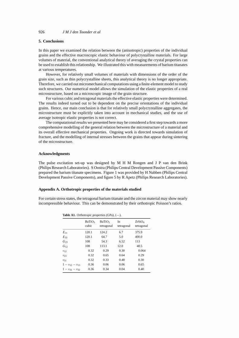
Appendix A. Orthotropic properties of the materials studied
For certain stress states, the tetragonal barium titanate and the zircon material may show nearlyincompressible behaviour. This can be demonstrated by their orthotropic Poisson’s ratios.
Table A1. Orthotropic properties (GPa), (—).
BaTiO3 BaTiO3 In ZrSiO4
cubic tetragonal tetragonal tetragonal
E11 120.1 124.2 6.7 375.9
E33 120.1 64.7 5.0 400.0
G23 108 54.3 6.52 113
G12 108 113.1 12.0 48.5
ν12 0.32 0.29 0.30 0.064
ν23 0.32 0.65 0.64 0.29
ν31 0.32 0.33 0.48 0.30
1− ν12− ν13 0.36 0.06 0.06 0.65
1− ν31− ν32 0.36 0.34 0.04 0.40
Single crystal elasticity and effective elastic behaviour 927
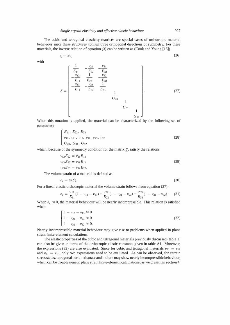
The cubic and tetragonal elasticity matrices are special cases of orthotropic materialbehaviour since these structures contain three orthogonal directions of symmetry. For thesematerials, the inverse relation of equation (3) can be written as (Cook and Young [16])
ε∼ = Sσ∼ (26)
with
S =
1
E11− ν21
E22− ν31
E33
− ν12
E11
1
E22− ν32
E33
− ν13
E11− ν23
E22
1
E331
G231
G311
G12
. (27)
When this notation is applied, the material can be characterized by the following set ofparameters
E11, E22, E33
ν12, ν21, ν13, ν31, ν23, ν32
G23, G31, G12
(28)
which, because of the symmetry condition for the matrixS, satisfy the relations
ν12E22 = ν21E11
ν13E33 = ν31E11 (29)
ν23E33 = ν32E22.
The volume strain of a material is defined as
εv = tr(E). (30)
For a linear elastic orthotropic material the volume strain follows from equation (27):
εv = σ11
E11(1− ν12− ν13) +
σ22
E22(1− ν21− ν23) +
σ33
E33(1− ν31− ν32). (31)
Whenεv ≈ 0, the material behaviour will be nearly incompressible. This relation is satisfiedwhen
1− ν12− ν13 ≈ 0
1− ν21− ν23 ≈ 0
1− ν31− ν32 ≈ 0.
(32)
Nearly incompressible material behaviour may give rise to problems when applied in planestrain finite-element calculations.
The elastic properties of the cubic and tetragonal materials previously discussed (table 1)can also be given in terms of the orthotropic elastic constants given in table A1. Moreover,the expressions (32) are also evaluated. Since for cubic and tetragonal materialsν21 = ν12
andν23 = ν13, only two expressions need to be evaluated. As can be observed, for certainstress states, tetragonal barium titanate and indium may show nearly incompressible behaviour,which can be troublesome in plane strain finite-element calculations, as we present in section 4.
928 J M J den Toonder et al
Appendix B. Element formulation
We used the FEM package MARC to carry out the calculations. The following elementformulations were used. Details of the elements may be found in [14].
For the plane strain calculations, MARC element 125 was used. This is a second-orderisoparametric two-dimensional plane strain triangular element with nodes at the three cornersand the three midsides. A disadvantage of this element is that distortion during solution maycause poor results. Therefore, as described in section 4.4, we also used element 11 for the planestrain calculations. This is a linear four-node isoparametric plane strain quadrilateral element.Although it is less sensitive to element distortions than element 125, shear behaviour may bepoorly represented. The shear behaviour may be improved by using an alternative interpolationfunction, such as the assumed strain procedure, which we also used. For nearly incompressiblebehaviour, use of element 11 may lead to element locking, which can be eliminated with useof the constant dilatation method, which we also applied to our problem (see section 4.4).
In the case of the plane stress calculations, we applied element 124, which is a quadraticsix-node plane stress triangle. Distortion of the element could lead to poor results, and aquadrilateral element would be preferable in that case. Since we concentrate on the planestrain calculations in this paper, results with the quadrilateral plane stress element are notreported here.
References
[1] Hennings D 1987 Barium titanate ceramic materials for dielectric useInt. J. High Technology Ceramics391–111[2] Grah M, Alzebdeh K, Sheng P Y, Vaudin M D, Bowman K J and Ostoja-Starzewski M 1996 Brittle-intergranular
failure in 2D microstructures: experiments and computer simulationsActa Mater.444002–18[3] Mullen R L, Ballarini R and Heuer A H 1997 Monte Carlo simulation of effective elastic constants of
polycrystalline thin filmsActa Mater.452247–55[4] Nye J F 1985Physical Properties of Crystals(Oxford: Clarendon)[5] Ting T C T 1996Anisotropic Elasticity: Theory and Applications(Oxford: Oxford University Press)[6] Hellwege K-H 1979 Numerical Data and Functional Relationships in Science and Technology
(Landolt–Bornstein New Series, group III, vol 11)(Berlin: Springer)[7] Berlincourt D and Jaffe H 1958 Elastic and piezoelectric coefficients of single-crystal barium titanatePhys. Rev.
111143–8[8] Hearmon R F S 1969 The elastic constants of polycrystalline aggregatesPhysics of the Solid State
ed S Balakrishne, M Krishnamurthi and B R Rao (New York: Academic) pp 401–14[9] Glandus J C 1981 Rupture fragile et resistance aux chocs thermiques de ceramiquesa usages mechaniquesPhD
ThesisUniversity of Limoges, France[10] Duffy W, Cheng B L, Gabbay M and Fantozzi G 1995 Anelastic behaviour of barium-titanate-based ceramic
materialsMetall. Mater. Trans.A 261735–9[11] 1996LEICA QWin Reference Guide & User GuideLeica Imaging Systems Ltd, Cambridge, UK[12] 1994MATLAB The Language of Technical Computing: Computation, Visualization, Programming: Version 5
(Natick, MA: MathWorks)[13] 1993SEPRAN Users Manual(Delft: Ingenieursbureau SEPRA)[14] 1994 MARC Analysis Research CorporationVolume A: User Information, Volume B: Element Library, Volume C:
Program Input(Palo Alto, CA: MARC)[15] Hughes T J R1987The Finite Element Method(Englewood Cliffs, NJ: Prentice-Hall)[16] Cook R D and Young W C 1985Advanced Mechanics of Materials(London: Macmillan)