Embed Size (px)
Citation preview

SCHOOL OF METALLURGY AND MATERIALS
THE UNIVESITY OF BIRMINGHAM
JULY 2010
The Reuse and Recycling of Glass Fibre Waste
By
Claire Fiona Wait
A thesis submitted to The University of Birmingham for the degree of MASTER OF
RESEARCH IN THE SCIENCE AND ENGINEERING OF MATERIALS

2
Abstract
This research project investigated the reuse and recycling of waste glass fibre fabrics
generated during the weaving process to produce filament wound composite tubes. The end-
use application for this filament wound tubes was to replace existing cardboard tubes used
within a weaving company. In other words, the glass fibre fabrics generated by the company
was used to manufacture a product that could be reused in-house. At present the cardboard
tubes are used as the core or mandrel to over-wind glass fabrics as they are woven.
Two different types of waste glass fibre fabrics were secured and used namely, “waste
slittings” and “direct loom waste”. The main emphasis was placed on producing tubes with a
surface smoothness that was equivalent to that of cardboard tubes. The other key requirement
was the filament wound tubes to have a uniform wall thickness.
A number of experiments were carried to optimise the filament winding process to enable
above-mentioned criteria to be achieved. The waste fabrics were impregnated using the so-
called “clean filament winding technology”. The filament wound tubes were evaluated using
standard test methods: density; fibre volume fraction; void content; interlaminar shear
strength (ILSS); hoop tensile strength; and lateral compression. Image analysis was also
carried out on all the tubes.
The filament wound tubes produced using waste slittings and a hybrid tube composed of
direct loom waste and waste slittings yield excellent surface-smooth finish and uniform wall
thickness; the surface-quality of these tubes were deemed suitable for over-wrapping woven
fabrics by the industrial sponsor of the project. The tubes produced using a hybrid of the
waste glass fibres from the weaving process has a superior lateral compression strength of
551.14 MPa when compared to the cardboard tubes which had an average of 68.14 MPa. The
inter-laminar shear strength for reference tubes (virgin glass fibres-hoop wound) was 46.73
MPa compared to 24.26 MPa for the hybrid tube. The average hoop tensile strength reference
tubes were 618.55 MPa where as the waste slittings tubes produced strength of 110 MPa. In
summary, the clean filament finding technique was adapted to enable filament wound tubes to
me manufactured from waste dry-glass fabrics. The mechanical properties of these tubes
suggest that they can replace the cardboard tubes that are currently used to over-wind the
glass fabrics during the weaving process.

3
Contents
1. Introduction .........................................................................................................................6
2. Aims and objectives ..........................................................................................................10
3. Literature review ...............................................................................................................11
3.1 EU legislations ................................................................................................................11
3.2 Techniques for Recycling Composites ...........................................................................15
3.2.1 Chemical Degradation..............................................................................................16
3.2.2 Thermal Degradation ...............................................................................................18
3.3 Characterisation of Recycled Fibres ...............................................................................20
3.4 Applications for Recycled Fibres ...................................................................................25
3.5 Summary.........................................................................................................................28
4. Experimental Methods..........................................................................................................28
4.1 Filament Winding ...........................................................................................................31
4.1.1 Conventional Filament Winding ..............................................................................31
4.1.2 Clean Filament Winding ..........................................................................................32
4.2 Materials .........................................................................................................................33
4.2.1 Direct Loom Waste ..................................................................................................33
4.2.2 Waste Slittings .........................................................................................................34
4.2.3 Resin and Hardener ..................................................................................................35
4.3 Tube Production..............................................................................................................35
4.3.1 Waste Slittings .........................................................................................................35
4.3.2. Direct Loom Waste (DLW) ....................................................................................40
4.3.3 Curing Process .........................................................................................................47
4.3.4 Mandrel Extraction...................................................................................................47
4.4 Physical Properties..........................................................................................................48
4
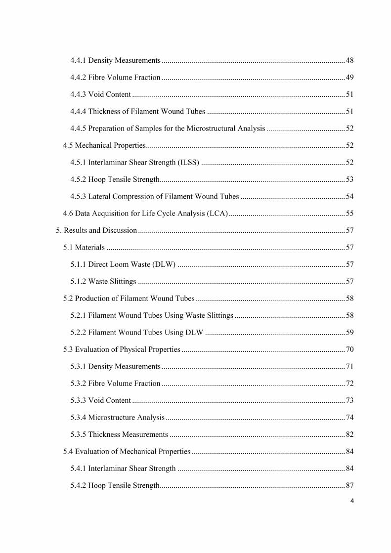
4.4.1 Density Measurements .............................................................................................48
4.4.2 Fibre Volume Fraction .............................................................................................49
4.4.3 Void Content ............................................................................................................51
4.4.4 Thickness of Filament Wound Tubes ......................................................................51
4.4.5 Preparation of Samples for the Microstructural Analysis ........................................52
4.5 Mechanical Properties.....................................................................................................52
4.5.1 Interlaminar Shear Strength (ILSS) .........................................................................52
4.5.2 Hoop Tensile Strength..............................................................................................53
4.5.3 Lateral Compression of Filament Wound Tubes .....................................................54
4.6 Data Acquisition for Life Cycle Analysis (LCA) ...........................................................55
5. Results and Discussion .........................................................................................................57
5.1 Materials .........................................................................................................................57
5.1.1 Direct Loom Waste (DLW) .....................................................................................57
5.1.2 Waste Slittings .........................................................................................................57
5.2 Production of Filament Wound Tubes............................................................................58
5.2.1 Filament Wound Tubes Using Waste Slittings ........................................................58
5.2.2 Filament Wound Tubes Using DLW .......................................................................59
5.3 Evaluation of Physical Properties ...................................................................................70
5.3.1 Density Measurements .............................................................................................71
5.3.2 Fibre Volume Fraction .............................................................................................72
5.3.3 Void Content ............................................................................................................73
5.3.4 Microstructure Analysis ...........................................................................................74
5.3.5 Thickness Measurements .........................................................................................82
5.4 Evaluation of Mechanical Properties ..............................................................................84
5.4.1 Interlaminar Shear Strength .....................................................................................84
5.4.2 Hoop Tensile Strength..............................................................................................87

5
5.4.3 Lateral Compression ................................................................................................89
5.5 Life Cycle Analysis (LCA) .........................................................................................90
6. Conclusion............................................................................................................................95
7. Future work ..........................................................................................................................97
8. References……………………………………………………………………………….…98

6
1. Introduction
Composites generally consist of two or more different materials or phases that when
combined exhibit a combination of both properties making them better than each of its
individual constituents. Reinforcement can be in the form of short or continuous fibres or
particulates.
Fibre reinforced polymers (FRP) are made from reinforcing fibres (glass, carbon and aramid
fibres) with a polymer matrix (thermoplastic or thermoset). FRP have high strength-to-weight
ratios thus making them ideal for high performance components in areas such as sports
equipment, structural components, automotive components, marine applications and
aerospace equipment.
In 2000, the output of composites was at 7 million tonnes and estimated to reach 10 million
tonnes in 2006. In 1992 (Ehrig), approximately 10%, or 12.6 million tonnes of waste
generated by the United States, is plastic with only 1% being recycled (Astrom 1997).
Thermoset scrap material in the US sent to landfill sites was estimated to be approximately
920,000 tonnes (Astrom 1997). European consumption of carbon fibre is currently around
2500 tonnes a year and of this approximately 80% is processed as prepreg and typically up to
40% is wasted as off-cuts (Unser and Stanley 1996).
The emphasis on recycling, disposal of unwanted product packaging and waste disposal in
general has enormous implications for the engineering manufacturing industry. The primary
EU legislations of relevance to composites are: (i) Directive 1999/31/EC on Landfill of
Waste, (ii) Directive 2000/76/EC for Incineration of Waste and (iii) Council Directive
2000/53/EC on End of Life Vehicles. Extended producer responsibility implies the polluter
should bear the cost of pollution. This cost should be reflected in costs of goods and services

7
that cause pollution in production and/or consumption. Extended producer responsibility can
also be seen as a strategy to internalize environmental costs into the market price (Forslind,
2005). Including a life cycle analysis (LCA) in all planning to consider energy, materials, and
disposal routes (including recycling) can be used to determine the most environmentally
friendly option that may not be obvious from the outset (de Brito et al. 2007).
FRP can be difficult to recycle due them containing two or more different components. The
polymer matrix can be either thermoplastic or thermosetting and this strongly influences the
recycling methods and avenues available to the composite.
Conroy et al. (2006) produced a hierarchy of waste in order to see the potential way to reduce
waste generated by composites. At the top of the hierarchy was waste minimisation in which
manufacturing processes are reviewed and possible methods of reducing production of waste
are identified. Reuse is the next level of waste reduction this generally means reusing
components in a downgraded structure. Composites can be very difficult to reuse because
they are generally made for specific applications. Composites can be ground up into small
granules, chips or sometimes a powder and then reused with virgin materials (Chu and
Sullivan 1996). Reuse of raw materials prior to final processing stages is another potential
way to minimizes waste. Recycling is the third stage of the hierarchy. Recycling is a process
by which composites that would otherwise become solid waste are collected, sorted, cleaned,
treated and reconstituted so they can be returned to the economic mainstream in the form of
raw material for new products. The recycling processes must be economically viable for the
manufacturer in order to promote recycling of composites. The process used would have to
be less of an environmental burden than the original disposal of the composite. The lowest
stage on the hierarchy is incineration, energy recovery and composting.
8
The focus of this study was to produce clean filament wound tubes using waste glass fibres
from the weaving process. The target of tube production was to produce a tube that could be
used within the weaving company (PD-Interglas technology) to replacing their existing
cardboard tubes. Waste glass fibre tubes should be able to exhibit more desirable properties
than cardboard tubes which are easily subjected to wear and damage during use.
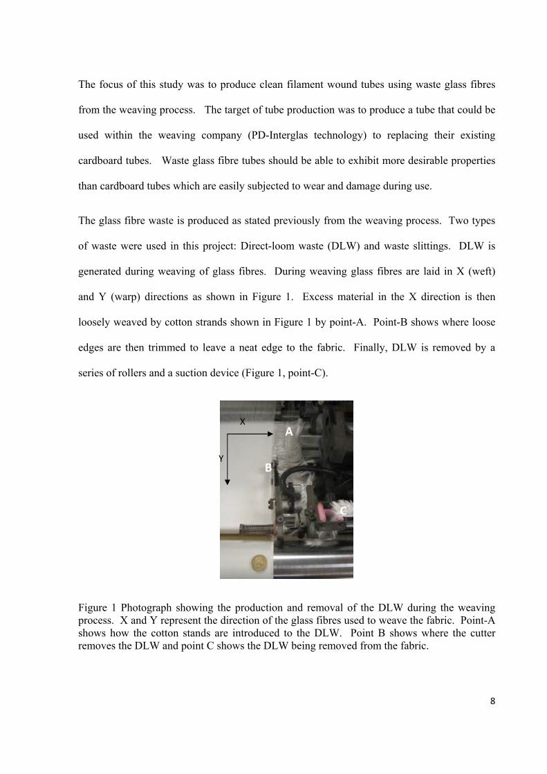
The glass fibre waste is produced as stated previously from the weaving process. Two types
of waste were used in this project: Direct-loom waste (DLW) and waste slittings. DLW is
generated during weaving of glass fibres. During weaving glass fibres are laid in X (weft)
and Y (warp) directions as shown in Figure 1. Excess material in the X direction is then
loosely weaved by cotton strands shown in Figure 1 by point-A. Point-B shows where loose
edges are then trimmed to leave a neat edge to the fabric. Finally, DLW is removed by a
series of rollers and a suction device (Figure 1, point-C).
Figure 1 Photograph showing the production and removal of the DLW during the weaving process. X and Y represent the direction of the glass fibres used to weave the fabric. Point-A shows how the cotton stands are introduced to the DLW. Point B shows where the cutter removes the DLW and point C shows the DLW being removed from the fabric.
X
Y
A
B
C

9
Waste slittings are produced during the “finishing” process the fabric is subjected to. This
process is shown in the schematic in Figure 2. The arrows show the direction the fabric
travels through the system.
Figure 2 Illustration of how the waste slittings are produced and removed from the glass fibre fabric. Point-1 shows processed fabric entering the system. Point-2 shows resin sealant applied to a series of rollers. Point-3 resin sealant is applied to the edges of fabric via a roller. Point-4 resin is cured as it travels to point-5 where a cutting roller is used to remove the resin-sealed edge. These are then removed from the system using a vacuum shown at point-6. Point-7 shows the post-trimming fabric being wound onto a mandrel for the customer.
1
2
3
4
5
67

10
2. Aims and objectives
The overall aim of this study was to investigate the feasibility of using waste from the
weaving process to produce tubes using the clean filament winding method. The specific
aims of this project were as follows.
i) To manufacture filament wound tubes using direct loom waste (DLW) and waste
slittings via the clean filament winding process.
The “clean filament winding” technique is a new manufacturing technique that was
developed to overcome the problems associated with conventional wet filament
winding. In the new process, the resin and hardener components are mixed on
demand and used to impregnate the reinforcing fibres using a custom-designed
impregnation unit. The clean filament winding technique is ideal for processing
delicate fabrics like the DLW because it is a low-tension manufacturing process.
ii) To assess the physical and mechanical properties achieved by the waste fibre tubes.
This will be completed by measuring the density, fibre volume fraction, void content,
image analysis and cross-sectional thickness to assess the physical properties. The
mechanical properties will then be assessed by completing interlaminar shear strength
tests, hoop tensile tests and lateral compression tests on all the sample tube produced.
iii) To review the literature and European Union legislation with regard to recycling of
composites
A detailed review was carried out to identify the state-of-the-art with regard to
recycling strategy, techniques and legislation.

11
3. Literature review
3.1 EU legislations
There is increasing public interest in the current environmental concerns with increasing
landfill taxes and a major push from the European Union on the disposal of fibre reinforced
polymers. Therefore it is important for manufacturers to ensure that they are disposing of
their waste in the most efficient and sustainable way without causing unnecessary damage to
the environment or human health.
It is important for manufacturers to develop strategies to meet the impending legislation that
will prohibit the disposal of composites in landfill sites as well as a decrease in the volume of
FRP that can be incinerated. These issues will obviously put more pressure on the need to
increase the recycling and reuse of FRP. The waste management scheme has been introduced
in order to give targets for the manufactures to achieve (Directive 2006/12/EC).
Directive 2006/12/EC was established with the main aim ‘to protect the environment and
human health against harmful effects caused by the collection, transport, treatment, storage
and tipping of waste. There are five main principles for the waste management framework.
The first stage is prevention to try and reduce the amount of waste generated. The second
principle is the ‘polluter pays’ which means that the manufacturer is responsible for the
environmental impact of the product throughout its life cycle. The third is precautionary in
order to try and see potential problems before they occur. The forth is reducing the waste.
This should be dealt with as close to the source of the waste as possible. Finally, the fifth is a
hierarchy of waste in which the waste should be disposed of as close to the top of the
hierarchy as possible in the prevention stage and try to reduce the amount of waste at the
bottom stage which is landfill in which no profit can be gained at all. The manufacturers and

12
the Member States should work together to ensure prevention or reduction of waste,
techniques to recover waste without harm to human health or the environment and all at no
cost to the consumer.
Landfill is a means of waste disposal onto or into a site on land. Since 1978 approximately
14,000 of the US landfill sites have been closed due to them being full, or because of
environmental issues (Rathje and Murphy, 1992). Directive 99/31/EC has been put in place
to reduce the amount of waste going to landfill and in particular hazardous waste to reduce the
negative effects on the environment in particular into surface water, groundwater, soil, air and
on global warming as well as any effects on human health. Waste can be categorised into
three groups’: municipal hazardous, non hazardous and inert. Different categories end up in
different landfill sites. Types of waste that are not allowed in landfills are liquid waste,
flammable waste, explosive or oxidizing waste, infectious hospital and clinical waste, used
tires and any other type of waste which does not meet the criteria stated in Annex II of this
directive. The prevention of landfill and recycling and recovery of waste should be the first
port of call for disposal of waste. Also the incineration of municipal and non-hazardous waste,
composting, biomethanisation and dredging sludge’s should all be considered prior to landfill.
Strict rules apply for landfill sites in that a record of waste dumped must be kept and any
damage to the environment or human health must be monitored. All waste must be treated
prior to being put into a landfill sites in order to remove any dangerous substances. Permits
for a landfill sites must be acquired in order for the site to operate with the criteria of the site
pointed out on the application form including how they plan on maintaining after care on the
site once full. Landfill is traditionally one of the largest forms of waste disposal for FRP but
with the taxes rising by 33% this year to £32 a tonne for 2008 and increasing £8 per year until

13
2010 as well as EU directives for disposal of waste alternate methods must be looked at as a
means of eliminating waste (Directive 99/31/EC).
The Directive 2000/76/EC on the Incineration of Waste was established to prevent negative
effects on the environment caused by the incineration process. Incineration is a thermal
treatment of wastes with or without recovery of the combustion heat generated. During this
process particular attention needs to be paid to the pollution caused by emissions into air, soil,
surface water and groundwater, which may result in a risk to human health. The aim is met
by stringent conditions placed on incineration of waste and technical requirements which do
not allow the emission limits set in the directive to be exceeded during the incineration
process. There is also an objective set to reduce dioxin emissions by 90 % from the sources
identified by 2005 (1985 level) and at least 70 % reduction from all pathways of cadmium
(Cd), mercury (Hg) and lead (Pb) emissions in 1995. Strict rules have been placed on the
transboundary movement of waste to other incineration plants (Council Regulation 3
259/93/EEC) to ensure that waste is not transferred for incineration or landfill sites which
operating at lower cost with less stringent rules causing more environmental damage. Also all
incineration plants in Europe must meet the standards required in order to be allowed to
operate. To help meet the objectives in the waste hierarchy (Directive 75/442/EEC),
requirements have been put in place for the recovery of heat generated by the incineration
process and for minimizing and recycling residues generated during the operation of
incineration plants.
Two European directives in particular have an enormous influence on the composite industry
they are the End-of-Life Vehicles (ELV) and the Waste Electrical and Electronic Equipment
(WEEE). With the main priority aimed at preventing these two forms of waste and to reuse

14
and recycle other forms of waste as to reduce the disposal of waste using the ‘polluter pays’
principle. The ELV directive 2000/53/EC states that by 2015 at least 85% of end-of-life
vehicles should be reused or recovered with a minimum of 80% being reused or recycled.
This is due to increase up to 95% for reuse and recovery and 85% for reuse and recycling on
vehicles at end of life after 2015. In order for these targets to be achieved the designs of
vehicles are beginning to alter so they can be dismantled and separated into materials using
component labeling. Collection of the waste must also be considered and limiting the use of
hazardous materials or preventing them altogether. Due to this directive many car
manufacturing companies are investigating the use of natural reinforcing fibres for composites
such as hemp, jute or cellulose as alternatives to carbon (professional engineering- recycling
law curbs of composites).
The WEEE directive 2002/96/EC is very similar to the EVL directive in that waste recovery is
maximized by reducing waste for disposal via reuse, recycling, composting and recovering
energy from waste and in doing so saving natural resources such as reinforcing fibres. Again
hazardous substances used in the components should be limited with new designs of
components making them easier to repair when broken and reuse or recycle. It is stated in the
directive that facilities should also be put in place so that the consumer can dispose of the
product in the most sustainable way. The recovery of components should be increased to a
minimum of 80 % by an average weight per appliance, and reuse and recycling shall be
increased to a minimum of 75 % by an average weight per appliance with these values
marginally altering depending on the category of waste the item is under.
With pressure mounting on the manufacturer to bear the cost of the environmental impact
during the life cycle of the product, due to legalization, it is important the manufacturers in
15
the composite industry begin to consider the best disposal methods for their waste. Due to
composites generally being produced for a specific application, the components themselves
are difficult the reuse. Therefore a strong focus on recycling must be investigated in order to
help meet legislation targets placed on the composites manufacturing industry and to reduce
their impact on the environment.
3.2 Techniques for Recycling Composites
Recycling of fibre reinforced polymers is an important area of research for manufacturers to
invest in. Recycling FRP will decrease the amount of waste deposited in landfill sites or
incinerated causing damage to the environment and meeting the increasing legislation set by
EU for the disposal of waste. Things that need to be considered when recycling composites
are the recycling technique itself does not result in more damage to the environment than the
existing production method for that material and the new composite can be recycled again.
This section will look at different methods of recycling FRP and the advantages and
disadvantages of each technique.
There are two types of FRP matrices: thermosetting and thermoplastic. Thermoplastic resin
matrixes are held together by weak Van-de-Waal bonds which break when heated and
“reconnect” when cooled. This means as the thermoplastic is heated it softens and eventually
becomes a liquid-melt, during cooling the liquid gets harder until it eventually form a solid
component again. This makes thermoplastics easier to recycle because during the melted
phase the composite mix can be placed into a new mould for reshaping to produce a new
composite component. Recycling methods for thermoplastics are described in detail in the
appendix section 1. This literature review mainly focuses on the recycling of FRP with a
thermosetting matrix which presents a problem when recycling because it cannot be melted

16
and reformed. Thermosets require a chemical reaction know as curing to convert liquid resin
into a solid polymer component. Curing involves a cross-linking process which occurs at a
particular temperature when a hardener initiates the cross-linking process. Cross-linking is
the reason thermosets cannot be melted and resolidified to form new components.
Thermosetting resins are used as matrixes instead of thermoplastic resin matrixes because the
cross-linking process of the resin means that solid structures produced are often stronger than
any thermoplastic. They are also much better suited to higher temperature applications
because they do not soften or creep significantly when heated. Thermosetting FRP are often
specialist and require properties from the thermoset that thermoplastics cannot match.
Effective recycling of thermosetting FRP is important so thermosetting composites can be
continually used without a huge impact on the environment.
There are four main recycling techniques for thermosetting FRP; size reduction, thermal
degradation, chemical degradation and energy recovery. This literature review focus’s on
thermal degradation and chemical degradation. Information size reduction and energy
recovery can be seen in section 2 and 3 in the appendix.
3.2.1 Chemical Degradation
Chemical degradation involves the use of chemical solvents at different temperatures which
when added to FRP composite cause the thermosetting matrix to degrade and breakdown so
fibres can be recovered. Chemical recycling requires the use of a chemical solvent to break
strong cross-linking bonds in thermosetting resin. In some cases the organic compound
produced from dissolution of the polymer can be a used for the formulation of new resins.
Dang et al. (2002) found bisphenol-F epoxy resin cured with 1, 8-p-menthanediamine would
completely decompose in a nitric acid solution. They used the products obtained from the

17
chemical decomposition and repolymerized them with an epoxy resin and curing agent to
prepare a recycled resin. Liu et al. (2004) used a nitric acid solution at 90 °C to decompose a
bisphenol-A epoxy resin matrix with curing agent IPDA and recover carbon fibres. Under
optimum conditions, epoxy resin was found to decompose rapidly and it was reported that the
fibre appeared unharmed and retained most of the strength.
A urethane-based matrix of scrap end-of-life vehicles with reinforcing carbon fibres was
found to completely degrade using a triethylene glycol/water solution at temperatures ~240
°C and carbon fibres could be recovered. However, the same treatment was not successful in
decomposing an epoxy-based substrate (Jody et al. 2004). Recent work completed by Jiang et
al. (2008) investigated using supercritical n-propanol to breakdown C-O-C and C-N-C bonds
of epoxy resin and obtain long-recycled carbon fibres maintaining the advantages of
continuous structure resulting in high strength. Supercritical n-propanol was used in a semi-
continuous flow reactor with a pressure of 5.2 MPa at 310 °C. Recycled carbon fibre cleaned
in an ultrasonic bath of acetone, followed by a fresh acetone rinse. Resulting carbon fibres
had similar tensile strength and Modulus to as-received carbon fibres with the main difference
in reduction of interfacial bonding strength when recycled fibres were added to epoxy resin to
produce a new composite.
A major disadvantage of using this process is different chemicals and solutions required to
degrade different types of polymer matrix due to different chemical bonds they can break.
Also recovered fibres require washing to remove residual chemicals and solvents from the
surface. There is a large amount of chemical waste produced during this process making it
less environmentally friendly. However this technique does enable recovery of fibres in
continuous form therefore composites produced using these fibres could potentially achieve
18
higher strengths due to continuous fibres reducing crack propagation through a composite
component.
3.2.2 Thermal Degradation
Thermal degradation of FRP matrix is achieved by pyrolysis. Pyrolysis is the removal of
thermosetting resin by thermally degrading the matrix component of the composite. The
pyrolysis process is shown in Figure 3. Pyrolysis involves heating a composite sample to a
moderate temperature in an oxygen-free environment until the volatile organic part (polymer
matrix) decomposes into gases and oils and the inorganic part remains unchanged (fibres,
fillers and char). These can then be recycled back into new polymeric products with little
changes made to the acquired components. Oil and gas are separated via cooling where they
can be collected and fibres are trapped in a mesh and extracted for use. Oil produced could be
added to petroleum or used directly as a fuel it is also an important source of chemicals which
can be used in other applications (Williams et al. 2005). Cunliffe & Williams (2003) found
oil produced could be used as a viable fuel when blended with suitable oils to increase the
flash point to meet UK and US health and safety legislation. Gas produced could be burnt to
power the pyrolysis system because emissions generated from the combustion of the gas lack
toxicity and hazards that are associated with normal incineration emissions (de Marco, et al.
2002). Recovered fibres are often covered in char and can require further heating to remove
any solid residue left on the fibres (Cunliffe & Williams, 2003). Fillers such calcium
carbonate can be used again as fillers in other composites. A study by Torres et al. (2000)
showed the optimum temperature for pyrolysis is between 400 ˚C and 500 ˚C. At
temperatures above this there was degradation of the CaCO3 filler and deterioration in
properties obtained from fibres recovered. Temperatures below 400 ˚C resulted in only
partial decomposition of the thermosetting matrix and fibres could not be removed. Torres et

19
al. (2000) found the sample only had to be held at final pyrolysis temperature for 30 minutes.
After this time no more pyrolysis products were produced. Average recovery achieved during
the pyrolysis process is approximately 98% therefore is an efficient recycling technique
especially if gas produced is used to power the process, this would reduce recycling cost for
the manufacturer.
Kennerley et al. (1998) found that using a fluidized bed pyrolysis process (hot bed of sand to
heat up composite) at 450 °C minimizes the degradation of recovered glass fibres. However
at this temperature the polymer did not completely combust, so a secondary higher
temperature heating process is required. After processing, around 60% weight of fibres
recovered was the filler. But washing of fibres demonstrated little contamination or filler
remained on fibres indicating that this process effectively removes the polymer and leaves the
fibres “clean”.
Figure 3 Schematic illustration of the pyrolysis process proposed by William et al. (2005). This shows where the sample composite is placed and the different stages of removal within the pyrolysis process. (Williams et al. 2005)
Composite Gas removal
Heater
Condenser
Condenser
Condenser

20
3.3 Characterisation of Recycled Fibres
One of the most valuable products obtained from FRP composite recycling processes are the
fibres (glass, carbon, aramid and natural). Reinforcing fibres are used in polymer matrixes
because they can increase specific strength, corrosion, wear and fire resistance as well as
insulation properties. Due to environmental concerns with disposal of fibres, there is great
interest in fibres generated from the recycling processes. If recycled fibres have similar
properties to virgin fibres, they could replace them. There would be a decreased requirement
in amount of virgin fibres produced and a disposal route for FRP rather than landfill or
incineration. It is therefore important that properties of recycled fibres are assessed to
determine potential uses for them.
Yip et al. (2002) recycled cured unidirectional carbon fibre/epoxy prepreg waste using a
fluidized bed process. SEM images showed the recovered fibres were relatively clean. They
showed that the longer the initial fibre length, the longer the average recovered fibre length,
but also the greater the degree of length degradation. There was little change found in fibre
diameter of recovered fibres at 450 ˚C demonstrating little apparent oxidation of carbon
fibres. This had been shown previously that temperatures below 550 °C cause little decrease
in the fibre diameter (Yin et al. 1994). Recovered carbon fibre shows very similar surface
chemistry to virgin carbon fibre with the surface atomic percentages changing very little.
However, there was a decrease of ~16% of O/C ratio on the surface of recovered fibres. This
indicates the amount of active sites on the surface of the carbon fibre available for chemical
bonding with resin. With very little of these functional groups lost during recycling there
should be little change in bonding strength with epoxy resin. Recycled fibres with a mean
length of 10 mm retained approximately 75% of their tensile strength, while the Young’s
modulus remained unchanged (Yip et al. 2002).

21
Cunliffe & Williams (2003) pyrolysed a thermoset polyester/styrene copolymer reinforced
with glass fibre. Recovered glass fibres were then tested by producing test plaques of glass
fibres/polyester resin. Plaques were made up using recovered fibre to replace 25 and 100 %
weight of virgin fibre content. After separation, recovered fibres showed no tendency to stick
together, indicating resin and sizing agent had been removed during the processing.
Microscopic analysis of virgin fibres showed a smooth, uniform surface. However, transverse
striations were seen along the surface of recovered fibres. These were thought to be due to
formation of micro-cracks changing the refractive index and contrast differences seen in the
optical image. These micro-cracks could result in micro-stresses in fibres. Addition of
recovered fibres into plaques decreased flexural strength, flexural modulus and Charpy impact
strength of plaques compared to control specimens. This deterioration was enhanced when
100% weight of recovered fibre was used. However, surface-finish of all the plaques
containing recovered fibre was very good implying recovered fibres might be more useful in
applications where high surface quality is important. Researchers also suggested a
replacement of 20% weight of virgin fibre with recovered fibres would still result in a product
that could meet manufacturers quality limits.
Jiang et al. (2008) investigated effects of thermal recycling on the change of surface
chemistry and actual interfacial bonding performance of recycled carbon fibre. Three
different types of carbon fibre/epoxy (Toray T600S, Toray T700S and Grafil MR60H) scrap
were used with about 64% weight of fibres. As-received fibres were provided to make
comparisons. The fibres were polyacrylonitrile (PAN) based high-strength fibre, and
contained a thin layer of epoxy resin size. Complete size removal was under taken on as-
received carbon fibre to use as a control (Jiang et al. 2008). Exposure of carbon fibre to hot
oxidative atmosphere during recycling process resulted in some of the surface hydroxyl

22
groups converting into a higher oxidation state (CO and COOH) though the O/C ratio was
still maintained. This meant interfacial bonding strength with epoxy resin was not affected
because as mentioned previously by Yip et al. (2002). T600S and T700S had similar
interfacial shear strength with the epoxy and MR60H had a much higher value. T600S and
T700S had smooth surface but the surface of the MR60H had shallow striations. MR60H and
T700S had similar O/C values which meant that higher interfacial shear strength of MR60H
could be attributed to striations on the surface, acting as a mechanical keying system. Other
researchers such as Cunliffe & Williams (2003) believe striations found on the surface of
fibres cause the decrease in mechanical properties of fibres. Therefore, there may be a
limitation between interfacial bonding strength obtained and mechanical properties achieved
when using recycled fibres in re-processed composites.
Scrap automotive sheet moulding compound glass fibre/polypropylene material was recycled
via pyrolysis by Allred & Busselle (2000). Glass fibres were recovered and examined using a
SEM and single fibre tensile tests. They were then compared to virgin fibres. The surface of
recovered fibres was found to be smooth with no evidence of pitting or other forms of surface
degradation. The processing of fibres had also left them clear of any resin residue on the
surface. Again in this experiment the single fibre tensile strength of the fibres recovered had
decreased quite significantly to around 50% of virgin fibre strength.
Liu et al. (2004) chemically degraded epoxy resin to recover carbon fibres. Carbon fibres
appeared undamaged and when tested, the loss in single fibre tension was only 1.1% which is
much better than fibres attained through thermal degradation processes. Jiang et al. (2008)
also found chemically degrading the polymer matrix left recycled fibres with very similar
mechanical properties as corresponding as-received carbon fibres however a reduction in the
interfacial bonding in new components was found to be a problem because the chemical

23
process had decreased the surface quantity of C-OH group’s thus decreased bonding strength.
Glass fibre/epoxy composites made of 67% weight of unidirectional glass fibre were recycled
chemically in 100 ml nitric acid solution (Yuyan et al. 2006). Epoxy resin was completely
removed and recovered glass fibres were incorporated into two different epoxy matrices to
form composites. The first was unidirectional continuous glass fibre with E-44/ IPDA epoxy
resin matrix and the second was made using 4–5mm short glass fibres cut from recovered
fibres with E-44/MeTHPA epoxy resin matrix. Two matching composites were made using
virgin fibres as reference samples. It was found that different operating conditions could
result in different characteristics. Samples under decomposition conditions of 70 °C for 250
hours, in a 6 M of nitric acid solution had a minimum fibre tensile strength loss of 3.5%,
while runs at 80 °C for 240 hours with 4M concentration of nitric acid solution produced a
maximum strength reduction of 15.1%. This is a much lower strength reduction than fibres
recovered through thermal processing. Pickering et al. (2000) measured a 50% reduction in
the strength of glass fibres after being recycled by the fluidized-bed process. Brearley and
Holloway, (1963) reported the residual strength of recycled fibres to be 33% of virgin fibres
when recovered from thermal recovery. Yuyan et al. (2006) observed recycled fibres using
SEM after chemical degradation. They found recovered glass fibres were free from residues
and arranged in an orderly manner, not seen in any thermal treatment methods which showed
fibres become entangled. Cunliffe & Williams, (2003) also showed the surface of recycled
fibres was smoother than virgin fibres with little contamination. This differs from striations
observed on fibres attained via thermal degradation treatment. When recycled fibres were
reused in a unidirectional continuous FRP there was a reduction in interlaminar shear stress
(ILSS) by 4.7% compared to virgin fibre composites and a strength reduction of only 2.5%.
The wetability of fibres was examined by looking at the contact angle of virgin and recycled

24
fibres with glycol to help predict their adhesion potential to matrices. Contact angle of virgin
fibres was 59.4° and for recycled fibres was 56.1°. Therefore it would be expected they
would have good adhesion to the matrices (Cunliffe & Williams, 2003).
The majority of fibres recovered for recycling processes are short-fibres generally caused by
wearing and breaking of fibres during the recycling process. The average strength of short-
fibres is greater than of long ones because the strength of fibre is limited by defects randomly
distributed along its length. However, if a fibre is too short, fibre pull-out can occur rather
than fibre breakage, reducing the strength of the composite. Therefore, effective fibre length
must be known in order to estimate ultimate strength of a composite this is shown in Figure 4.
Effective fibre length can be predicted using the concept of critical length developed by Kelly
and Tyson (1956). Factors influencing critical length include fibre diameter, relative moduli
and strengths of resin and fibre, shrinkage stress, friction, and adhesion (Hughes et al. 1980).
Figure 4 Illustration showing the critical length of a shot fibre. The variation of the tensile stress, σ in the fibre and the shear stress, τ, at the interface along the length of a short-fibre embedded in a matrix. The calculation is based on the Cox (1952) shear-lag model related to a

25
1000 µm length of carbon fibre in an epoxy resin matrix. Source: Introduction to composite materials: Hull and Clyne
3.4 Applications for Recycled Fibres
To make FRP recycling viable, there must be potential applications in which components
generated from recycled fibres can be used. Recycled FRP composites must meet certain
criteria to determine whether the new composite produced is worth producing. Conroy et al.
(2006) listed criteria for the use of recycled material these are described in the appendix in
section 2.
Different components can be produced from different recycling techniques, allowing for
many different recycling avenues. Products can be produced using recyclate material
generated on grinding the composite, prepregnated waste from cut offs when manufacturing
components to specific dimensions. Individual components such as fibres and fillers from
thermal or chemical removal can be recycled back into components.
One method of recycling is to recycle waste prepregs. This is waste that consists of
reinforcing fibres impregnated with resin which has not been cured. This particular type of
FRP waste can be used to face a sheet of plywood which can then be used in applications such
as concrete forming (Hurd, 1997). The sheet can be manufactured by compressing the
prepreg waste and heating until the resin is cured which produces a solid composite. Hurd
(1997) found a composite layer increased strength and surface wearability of plywood. The
overlay of the composite on the plywood can give a better surface finish to concrete and also
increase the amount of times plywood can be used.
Another potential application is to use the prepreg as an adhesive reinforcement between
laminates in timber beams. There are two main problems associated with bonded timber
laminates; one is long term creep deflection due to sustained loading and the second is their

26
lower flexural stiffness. Dolan et al. (1997) undertook a pilot study to investigate the
feasibility of using a FRP as glue to reduce the mentioned problems found when using
adhesives. It was found flexural strength was significantly improved without any decrease to
appearance or bond-line integrity of the glue. A similar product produced is Glulam timber, a
combination of inexpensive soft wood combined with a thermosetting plastic composite. This
product has been used in structural applications such a motorway bridges, buildings and
structural aesthetics (Dolan et al. (1997). This product is more environmentally friendly than
steel requiring six times less energy to produce an I-beam with the same strength. It showed
good insulation properties and is light-weight compared to other structural components.
Glulam has good chemical resistance and is more economical to use in construction
(www.glulam.co.uk). Stewart et al. (2004) used waste cut-offs from a laminating company to
produce tiles. They found a range of densities were present in the tiles with some separation
and voids found in tiles. Tiles produced using woven fibreglass were found to have properties
similar to a traditional quarry tile. However, there was a concern about the cost of a
composite tile.
Demura et al. (1995) produced artificial wood in an autoclave with various compositions of
ground recyclate waste which were combined with sawdust (wood manufacturing waste
product). They found artificial wood was inexpensive to produce and it displayed similar
properties to natural wood in the way it could be nailed and sawn. Addition of ground glass
fibres to plastic lumber improved some properties of synthetic wood, for example increasing
tensile strength and flexural modulus, but decreasing impact strength. The best properties
were achieved when glass fibre and wood dust were used together rather than separately
(Stewart et al. 2004). The new plastic lumber was found to be more durable in a marine
environment than natural timber (Conroy et al. 2006). FRP recyclate has been used to

27
reinforce commercial chipboard for use in domestic flooring because it requires lower energy
input to produce than chipboard and does not need drying before use (Conroy et al. 2006)
FRP recyclate is also easily moulded into shapes and gives a good surface finish (Conroy et
al. 2006).
FRP recyclate has also been used to improve the strength of asphalt. Woodside et al. (2003)
incorporated glass fibre reinforced polymers into 20 mm dense bitumen to investigate any
enhancement in properties. They found using 1% of ground FRP, the property improvements
were minimal. Palermo (1992) also considered FRP recyclate as an alternative material for
use in asphalt because it has high wear resistance, chemical resistance and is also an effective
noise absorber.
Materials gathered from the degradation of the polymer matrix in a composite include fibres,
fillers and char. Fibres obtained from thermal and chemical recycling could be reused to
produce a new component in a secondary application because of the variable inferior
properties to the original material demonstrated by studies mentioned in previous sections.
Fibres can be remoulded with a new polymer resin to produce sheet moulding compound and
bulk moulding compounds in applications such as low load structural components, electrical
applications, automotive and corrosion resistant appliances. Fibres can also be used as
insulation materials and is also an effective acoustic barrier (Palermo, 1992). Fibres can be
used in low grade insulation with char residue still on (Conroy et al. 2006).
Bartl et al. (2005), recovered fibres from waste tyres and looked at them as reinforcement for
improving the properties of bitumen. The West European fibre market for tyres was about
86,000 tonnes in 2002 (Bartl et al. 2005). Fibres used in tyre manufacturing processes consist
of cellulose (37%), polyester (27%), nylon (20%) and cotton (2%) (CIRFS, 2004). The GVG

28
recycling plant supplied ground waste fibres. Due to the grinding process, the handling
properties improved from a wadding-like material (fluff balls) to a powder-like product
making processing easier. The ground samples, some original fibre samples from the
recycling plant and a commercially available product called Arbocel® (ground cellulose)
(Rettenmaier, 1988), were analysed by the MorFi system which provides data on shape and
size of fibres. The average length of the recycled fibres after grinding was decreased from
original material and average width remained about the same. When adding recycled fibres to
pure bitumen there was an increase in stability. At approximately 68 ˚C, pure bitumen can
result in early failure of an asphalt pavement by deformation. When fibre reinforcements are
added (10 % mass of fibres) to bitumen it is able to withstand higher temperatures, up to 80
˚C. Therefore fibre reinforced bitumen should be more resistant to rutting and grooves made
by passing vehicles. However, viscosity also increases, making workability harder.
Therefore the addition of fibres was limited. With just a 6% mass of fibres workability of
bitumen was good and there was still significant improvement of high temperature properties
of the bitumen. The stiffness of bitumen was also found to increase. Addition of fibres to
bitumen was found to worsen its properties at low temperature. However, there was more
distinct improvement at high temperatures which may be more important especially in warm
climates.
3.5 Summary
A detailed review of the literature was undertaken to identify strategies and techniques that
have been used to recycling glass and carbon fibre reinforced composites. Whilst significant
attention has been given to recycling fibre reinforced composites, only a few studies have
considered the recycling and reuse of dry glass fabrics. Furthermore, little attention has been
given in the literature to the use of waste dry-fabrics to manufacture and replace products that
29
are purchased; for example, replacing cardboard tubes with filament wound tubes
manufactured from waste dry glass fabrics.
Due to legislation, public awareness and demand for recycling and reuse of composite
material, manufacturers have to consider these issues during the whole life cycle of the
product including the design and manufacturing stages. End-of-life strategies for fibre
reinforced composites is also an important issue that needs to be considered and addressed.
The literature review has identified several methods that are used to recycle composites. It
has been claimed that some recycling techniques produce fibres with properties similar to
those obtained of virgin fibres. Much of the literature so far on applications of recycled fibres
describes their use in the construction industry such a concrete reinforcement and
reinforcement in bitumen on road surfaces. There seems to be a lack of research reported on
the reuse of fibres in load-bearing applications. This may in part be due to the fact that most
recycling processes mainly recover short-fibres as opposed to continuous reinforcement. As a
consequence, end-used applications involving short-fibres are still limited to injection
moulding and related techniques.
Form the literature reviewed it can be seen that there is a lack of research into the reuse of
waste glass fibres within a composite that generates the waste. In other words, the generator
of the waste developing techniques to reuse the waste for in-house applications or for sale into
other market sectors.
The current study has developed a practical method for manufacturing commercially valuable
products from dry-waste glass fibre fabrics. This can not only help to reduce the
environmental impact of waste glass fibres by avoiding disposal in landfill sites and

30
incineration. This study has also developed a viable outlet for glass fibre waste and thus has
made a positive contribution to meet EU legislations.
In summary, this project investigated the reuse of two waste glass fibre products from a
weaver of technical glass fibre fabrics for the aerospace and wind energy sectors. The
recycled waste was used in the production of filament wound tubes to replace cardboard
tubes. Their mechanical and physical properties were assessed and particular attention was
paid to acquiring the best surface-finish and uniform wall thickness.
As a consequence of the current study, site-trials were carried out to manufacture 2-metre
long filament wound tubes from the waste slittings; the inner bore diameter of this tube was
169 mm. These filament wound tubes will be assessed on-site by a company that weaves
technical glass fabrics to replace the cardboard tubes that are used to over-wind fabrics.

31
4. Experimental Methods
4.1 Filament Winding
4.1.1 Conventional Filament Winding
A conventional filament winding process is shown in Figure 5. Continuous fibres are pulled
off a creel and directed into a resin bath. Resin and hardener ratios are measured out and
mixed within the resin bath. The resin bath has a roller which fibres are directed around.
Fibres leave the resin bath after impregnation and are directed by a series of rollers onto a
rotating mandrel. At the end of each day the resin bath must be emptied of left over waste
resin and needs to be cured and disposed. Solvent must be used to clean all equipment after
each production run. Adequate vapour recovery systems are required to protect workers and
meet emission limits.
Figure 5 Schematic illustration of the conventional wet-filament winding technique (Pandita et al. 2007). Labelled are the key components of the system:(A) Fibre creels, (B) Tensioning system, (C) Traverse, (D) Mandrel, (E) Resin bath and (F) Fibre bundles.

32
4.1.2 Clean Filament Winding
The clean filament winding technique was used to produce continuous fibre reinforced
composite tubes (Pandita, et al 2007). Figure 6 illustrates the experimental set up for clean
filament winding. Clean filament winding uses a resin injector instead of a resin bath. This
allows the resin and hardener to be stored separately, reducing the amount of solvent used and
resin wasted. This means there is a cleaner environment for workers and cleaning time is
reduced significantly (Pandita, et al 2007). Fibres are pulled off a bobbin enters a series of
rollers, passes through an injector system and is then wound around a rotating mandrel. The
injector system consists of a static mixer and resin impregnator. The static mixer mixes the
resin and hardener and directly impregnates fibres as they are pulled through. Waste material
was placed directly into the existing clean filament winding system with no alterations made
to material or machine.
Figure 6 Schematic illustration of the Clean Filament Winding process; note that the resin-bath has been eliminated from the manufacturing process. The key components are coded as follows: (A) Fibre creels, (B) Tensioning system, (C) Traverse, (D) Mandrel, (E) Impregnation unit and (F) Fibre bundles (Pandita et al. 2007).

33
During production of all tubes, left limit on the mandrel was 175 mm and right limit was 400
mm. One dwell turn was set at the end of each layer before the fabric was wound back down
the tube.
4.2 Materials
4.2.1 Direct Loom Waste
Direct loom waste (DLW) gathered during the weaving process supplied by PD-Interglas
Technology. Removal of DLW gives a straight edge to the fabric shown in Figure 9. The
glass fibre waste has a starch /oil binder still present which is added to help ease the weaving
process. This is usually removed prior to use. This may have an impact on bonding strength
between glass fibres and epoxy/amine resin when used directly in the experiment. The length
of glass fibres varies but on average, fibres are around 70 mm. Fibres lie in a perpendicular
direction to the glass fibres shown in Figure 7.
Figure 8 demonstrates the distances of fabric held in the cotton strands and the variable length
of loose fibres from the last cotton strand to the end of the glass fibre. Variations in the waste
material depend on the fabric weave and weaving machine DLW is gathered from. During
processing of all DLW tubes, cotton fibres were retained in the waste glass fibres.

34
Figure 9 Photograph showing how the DLW is produced during the weaving process.
4.2.2 Waste Slittings
Waste slittings are acquired during the “finishing” process detailed in the introduction. Waste
slitting material differs from DLW because it has been heat-cleaned so the starch/oil binder
has been removed. The material has also been silane finished and a resin sealant has been
Figure 7 Photograph of DLW compared to the continuous glass fibres used in the existing clean filament winding system.
Figure 8 Photograph showing the variability in two strips of DLW from two separate fabric productions. The cotton strands lie perpendicular to the glass fibres with one double cotton strand and six other single weaved strands of cotton
35 mm 45 mm
Direct loom waste (DLW)
Cutting device
Fabric

35
applied to stabilise the edge during cutting of the finished fabric shown in figures 10 and 11.
Waste slittings vary in width but on average are around 15 mm.
4.2.3 Resin and Hardener
The resin system used for both DLW and waste slittings was LY3505 resin and XB3403
hardener supplied by Huntsman Advanced Materials, UK.
4.3 Tube Production
4.3.1 Waste Slittings
A summary of tubes produced using waste slittings is shown in Table 1. The scale of all
images of filament wound tubes during production can be inferred by the outer diameter of
the mandrel which is 100 mm.
Figure 10 Photograph to show the rollers which apply the resin sealant to the edge of the glass fibre fabric.
Figure 11 Photograph showing a close up of a section of the waste slittings.

36
Tube 1-Wound as received into existing filament winding system
Tube 2 - Increased tension at 7 mm pitch
Tube 3 - Increased tension at 20 mm pitch
Tube 4 – Decreased winding speed
A B C D
Table 1 Summary of all the tubes produced using the waste slittings in the order of production. Tube-A was wound directly in the existing clean filament winding system from the creel received from PD-Interglas. Tube-B was wound under tension at a 7 mm pitch. Tube-C was wound under tension at a 20 mm pitch. Tube-D was wound using a second batch of waste slittings; it was wound under tension with a 7 mm pitch at a decreased winding speed.
4.3.1.1 As‐Received Waste Slittings
Two layers of as-received waste slittings shown in Figure 12 were wound around the mandrel.
The slittings were pulled off the bobbin, passed through a set of rollers on the injector
platform entered the injector system and finally were wound around the mandrel. This
process is shown in Figure 13.

37
4.3.1.2. Waste Slittings Manufactured Using a 7 mm Pitch
Four layers of waste slittings was wound at a speed of 50 rpm (revolutions of the mandrel per
minute, 15.7 m) and injection ratio of 13:13. Tension placed on the fabric was increased by
introducing a series of rollers for the fabric to go through shown in the schematic in Figure
14.
Figure 14 Schematic of the tensioning system placed on the waste slittings fabric. The arrows show the direction of the waste slittings as it is pulled through the tensioning system. The area within the dotted box is the tensioning system added to the filament winding set up.
Figure 12 Photograph showing the as received waste slittings on the creel.
Figure 13 Photograph to show the as received waste slittings wound on to the mandrel.

38
Increasing the amount of rollers increased the amount of surface contact on the fabric
increasing friction and therefore increasing fabric tension. The new tube is shown in Figure
15.
Figure 15 Photograph showing the 7 mm pitch slitting waste tube during the winding process.
4.3.1.3 Waste Slitting 20mm Pitch
The next tube produced was 4-layers of waste slittings. This was wound with the same resin
injector ratio and speed, and subjected to the same tensioning system. For this tube was the
pitch was adjusted to 20 mm to generate a different winding pattern that optimised coverage
of waste slittings on the mandrel. The tube produced is shown in Figure 16 and a close up in
Figure 17.

39
4.3.1.4 Waste Slittings 7 mm and Over Impregnated
During production of this tube 4-layers of waste slitting were wound at a 7 mm pitch under
the same tensioning system as mentioned previously. However, injection ratio was increases
to 15:15 and winding speed was reduce to 20 rpm therefore increasing the time waste slitting
spent in the injector system thus increasing time of impregnation. This was necessary because
previous tubes were not impregnated sufficiently with resin.
Figure 16 Photograph to show the 20mm pitch tube during the production.
Figure 17 Photograph showing a close up of the surface of the 20mm pitch tube during

40
4.3.2. Direct Loom Waste (DLW)
The tables below show a summary of the tubes produced using the DLW in order of their
production.
As-recieved DLW/DLW/Peel-ply GF/DLW/DLW/GF
Glass Fibre DLW
DLW
DLW DLW
DLW
DLW
Peel-ply Glass Fibre
A B
C
Table 2 Summary of the first three tubes produced using the direct loom waste. Image- A shows the tube produced using two layers of DLW. Image -B shows the tube produced using two layers of DLW and a layer of peel-ply. Image-C shows the tube produced using continuous glass fibre with two layers of DLW and a final layer of continuous glass fibre

41
Hybrid tube
Waste slittings
DLW
DLW
Waste slittings
G
DLW – Tension DLW – Folding DLW- Sewn
DLW DLW DLW
DLW DLW DLW
Peel-ply Peel-ply 2inch Masking tape
D
E
F
Tables 3 Summary of the next four tubes produced using the direct loom waste. Image-D shows the tube produced when the two layers of DLW were wound under tension as well as the final layer of pee-ply. Image-E shows the tube produced when folding the edges of the DLW. Image-F shows the tube produced when the loose edges of the DLW were sewn prior to being wound. Image-G shows the hybrid tube produced using one layer of waste slittings followed by two layers of DLW and a final layer of waste slitting.

42
4.3.2.1 As‐Received Tube 1
The first tube wound consisted of 2-layers of DLW. During the first layer of winding, resin
was concentrated over the cotton strands, so loose ends of the waste glass was not coated in
resin demonstrated in Figure 18. However, as the second layer wound back over the first, the
loose fibres became impregnated with resin due to the layer of DLW being wound over the
top shown in Figure 19.
4.3.2.2 Two Layers of DLW and One Layer of Peel‐Ply
This tube also consisted of 2-layers of DLW shown in Figure 20. After the 2-layers were
wound a third layer of peel-ply was wound over the top to give the tube a smoother surface
illustrated in Figure 21. The definition of peel-ply can be found in the appendix section 5.
After peel-ply was applied the mandrel was removed and placed in the oven. The peel-ply
was left on after curing to ensure a good surface finish.
Figure 18 show the hedge hog appearance of the first layer of DLW has been wound.
Figure 19 show the hedge hog appearance of the first layer of DLW being trapped by the second layer of DLW applied.

43
4.3.2.3 Glass Fibre/Direct Loom Waste/Direct Loom Waste/Glass Fibre
The first layer was wound using continuous glass fibre shown in Figure 22. This was
followed by 2-layers of DLW and one final layer of continuous glass fibre. Figure 23 shows
continuous glass fibres being wound onto the second layer of DLW.
Figure 20 Photograph showing the tube produced after a second layer of DLW was applied.
Figure 21 Photograph to show the layer of peel-ply applied to the tube after the two layers of DLW.
Figure 22 Photograph showing a layer of DLW being applied to a layer of virgin continuous glass fibres.
Figure 23 Photograph to show a layer of virgin continuous glass fibres being applied after two layers of DLW have been wound.
100 mm

44
4.3.2.4. Direct Loom Waste Wound under Tension
DLW was passed through the directional rollers as with previous experiments. DLW then
passed through a series of rollers as seen in Figure 14 for waste slittings. On the injector
platform the fabric passed though another set of rollers and entered the injector. The speed
was set at 4 rpm (1.25 meters). Two layers of DLW fabric were wound shown in Figure 24
with a third layer of peal ply added shown in Figure 25. Pitch was set at 20 mm with the
injection ratio of resin and hardener set at 16:16.
4.3.2.5 Folding Loose Edges of DLW
The DLW again went through the directional rollers. However, instead of passing through a
tensioning system DLW went directly onto the two rollers on the injection platform. As the
DLW left the top roller it then passed through a tapered metal tube which was angled to meet
the injector shown by the schematic in Figure 26. The aim was to cause the fabric to fold in
half as it entered the injector. DLW then passed through a second metal tube also tapered in
order to keep the fabric folded as it was wound onto the mandrel. Figure 27 shows folding of
Figure 24 Photograph to show the tube produced after a second layer of DLW has been applied to the mandrel under tension.
Figure 25 Photograph showing the tube produced after a layer of peel-ply has been applied to the two layers of DLW also under tension.

45
the loose edges of the DLW. Two layers of folded DLW were wound and a layer of peel-ply
was added under tension.
Figure 26 Schematic illustration of the set up used to fold the loose edges of the DLW. Point-1 shows the DLW entering the set up. Points-2 show the metal tubing used to fold the fabric. Point-3 shows the injector system and point-4 shows the folded fabric leaving to be wound around the mandrel.
1
2
3
2
2
4
Figure 27 Photograph showing the second layer of the folded DLW as it leaves the folding set up and is wound around the mandrel.

46
4.3.2.6 Sewing Loose Edges of Direct Loom Waste
Before production of the sixth tube, DLW passed through a conventional sewing machine.
This sewed the loose edges of DLW together and added a double cotton stitch to the opposite
end of DLW. Figure 28 shows loose edges of DLW being sewn. Sewn DLW was wound
back on to the bobbin ready to be wound onto the mandrel. Sewn DLW was directed straight
through two rollers on injection platform and into the injector. Sewn DLW was wound onto
the mandrel with a 7 mm pitch at 20 rpm (6.3 meters) and injection ratio of 13:13. Two
layers of sewn DLW were wound shown in Figure 29 followed by a layer of masking tape.
4.3.2.7 Hybrid Tube of Waste Slittings and DLW
The hybrid tube was produced using 1-layer of slittings followed by 2-layers of DLW and a
final layer of waste slittings. Both layers of waste slittings were wound under tension at a 7
mm pitch at 20 rpm with an injection ratio 15:15. The 2-layers of DLW were wound at a
pitch of 7mm and a speed of 10 rpm (3.15 meters) shown in Figure 30. Injector ratio
Figure 28 Photograph to show how the extra cotton strand was sewn onto the DLW using a traditional sewing machine.
Figure 29 Photograph showing the tube produced using two layers of sewn DLW.

47
remained the same as there was excess resin on the waste slitting that DLW soaked up.
Figure 31 shows the final layer of waste slittings added to the tube.
4.3.3 Curing Process
After processing the mandrel was removed from the filament winding machine and placed in
an oven (Catherm Ltd.) at 70 °C for six hours to cross-link (“cure”) the matrix.
4.3.4 Mandrel Extraction
Once the tubes had cured, they were removed from the mandrel using a mandrel extractor.
The mandrel extractor used to extract the tubes is shown in Figure 32. Each mandrel was
placed in the extractor and a manually-powered hydraulic ram was used to push the mandrel
out from the inside of the fibre tube.
Figure 30 Photograph showing the first layer of DLW applied to a layer of the waste slittings.
Figure 31 Photograph to show the outer layer of waste slittings as it was applied to two layers of the DLW.

48
Figure 32 Photograph showing mandrel extractor system with a glass fibre filament wound tube prior to extraction.
4.4 Physical Properties
4.4.1 Density Measurements
Density of 5 samples from each batch of tubes was measured using the density determination
kit AP250D shown in Figure 33. Weight and buoyancy of samples was taken and
temperature of water was measured and converted into a density measurement of the liquid.
Equation (1) was used to calculate the density of the samples. These tests were carried out in
accordance with ASTM D792-00.
Equation (1)
Manually powered hydraulic Ram
30 cm ruler
Glass fibre tube on the mandrel.
Mandrel extraction through circular hole that removes the tube.

49
Figure 33 photograph to show the experimental set up for measuring the density of samples.
4.4.2 Fibre Volume Fraction
The technique used to determine fibre volume fraction was the resin burn-off technique
described in ASTM D2584. Five samples from each waste glass fibre tube were placed into
crucibles and put in a furnace at 600˚C for 6 hours to burn of the polymer matrix. Figure 34
demonstrates how the crucibles were placed in the oven. Full details of the procedure are in
the appendix section 6.

50
Figure 34 Photograph showing 5 samples in crucibles placed in the oven ready for the resin burn off.
The fibre volume fraction was calculated using Equation (2).
Where:
Wg = Sample weight (after heat treatment in the furnace).
W Comp = Sample weight (before heat treatment in the furnace).
V Comp = Volume of Composite.
V Glass = Volume of Glass.
Vf % = Percent volume fraction.
%100% ×==Comp
g
Comp
Glassf W
WVVV
Equation (2).

51
4.4.3 Void Content
Void content was calculated using the results gathered from percent fibre volume fraction.
Once fibre volume and resin volume have been found the remaining volume is the void
content. Measurements were carried out in accordance to ASTM D2734.
4.4.4 Thickness of Filament Wound Tubes
One hybrid tube was marked into 6, 15 mm rings. One point was selected on the tube to be at
point-1 on every tube. The tube was cut into 15 mm rings and the edges were ground and
polished using 2500 μm grade paper. Each ring was photographed loaded onto ImageJ™
software where 7 further points were located on the tube using point-1 as the reference point
shown in Figure 35. Using ImageJ™ software the thickness of the tube at each of the 8 points
was measured and recorded.
Figure 35 Photograph demonstrating how the points 1 to 8 were selected for thickness measurements. The measurements was recorded and used to work out the average thickness of the hybrid waste tube.

52
4.4.5 Preparation of Samples for the Microstructural Analysis
Two sections from each sample ring were placed into mounting pots and filled with epoxyfix
resin and hardener at a ratio of 5:1. Once hardened, samples were removed from the pots.
Hand grinding was carried out on all samples (240, 400, 1200 grade sand paper). Samples
were then placed in a mechanical polishing machine. Alumina 0.05 μm solution was used as
the polishing agent. Samples were placed in an ultrasonic cleaner for 10 minutes, cleaned
with ethanol and then dried before being viewed under the optical microscope.
4.5 Mechanical Properties
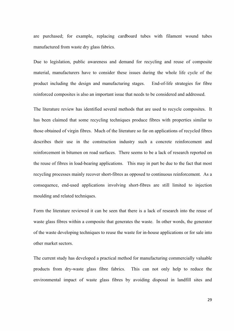
4.5.1 Interlaminar Shear Strength (ILSS)
ILST was tested using standard D2344/D2344M to test a curved laminate sample. To attain
the length of the sample required, the thickness was x 6 and to find the width x 2. This test
procedure could only be used if the sample curvature was lower than 30°. Specimens cut
from the tube were placed in a 3-point-bend rig shown in Figures 36 & 37. The crosshead
movement was 1 mm/min and data was recorded onto a computer. Sample was tested until
failure occurred.
53
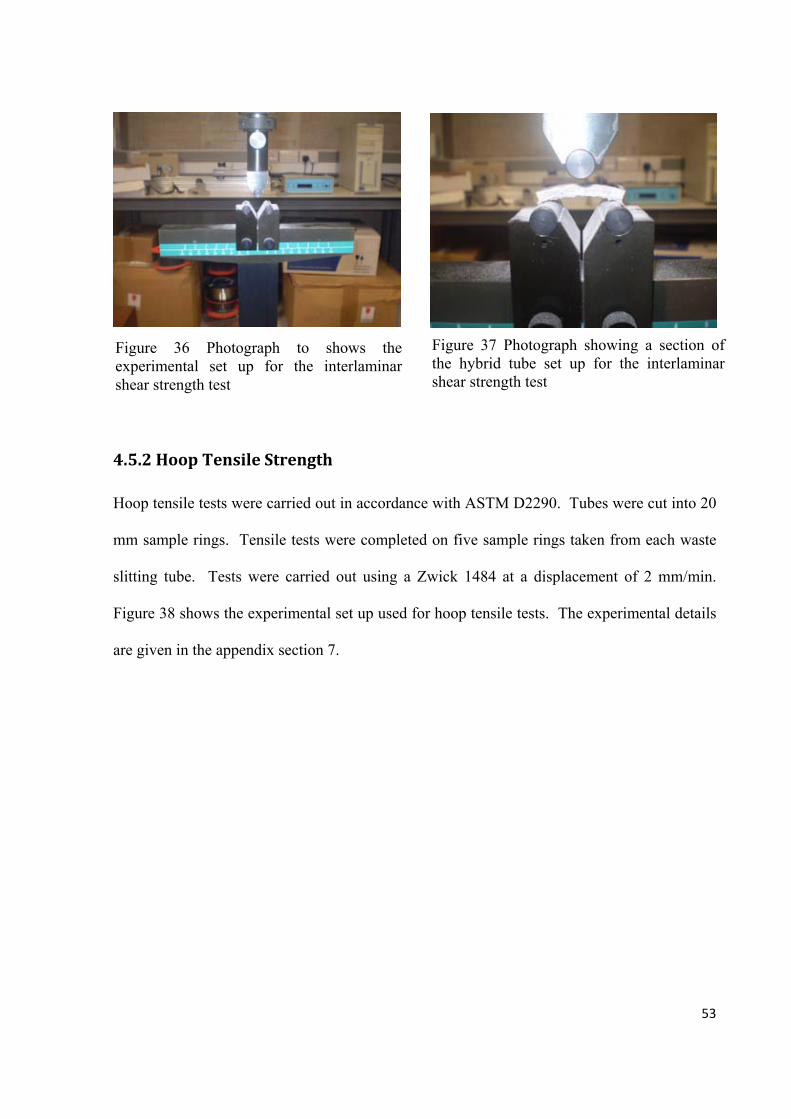
4.5.2 Hoop Tensile Strength
Hoop tensile tests were carried out in accordance with ASTM D2290. Tubes were cut into 20
mm sample rings. Tensile tests were completed on five sample rings taken from each waste
slitting tube. Tests were carried out using a Zwick 1484 at a displacement of 2 mm/min.
Figure 38 shows the experimental set up used for hoop tensile tests. The experimental details
are given in the appendix section 7.
Figure 36 Photograph to shows the experimental set up for the interlaminar shear strength test
Figure 37 Photograph showing a section of the hybrid tube set up for the interlaminar shear strength test

54
Figure 38 Schematic illustration of the experimental setup used to test the hoop tensile strength.
4.5.3 Lateral Compression of Filament Wound Tubes
Lateral compressive strength was estimated using the method outlined by Gupta and Abbas
(2000) Cardboard and hybrid waste tubes were cut into 15 mm width rings. Compression
tests were carried out on an Instron 5566 at cross-head displacement rate of 1 mm/min.
Average width and thickness were taken using five different sections of the sample. The
results were plotted onto a force/displacement graph. Figure 39 shows the experimental setup
used to carry out this experiment.
Sample ring 20mm width
Connections to the Zwick 1484 pulled at a displacement of 2 mm/min
Metal inserts fitting the internal diameter of the
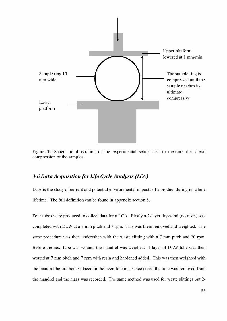
55
Figure 39 Schematic illustration of the experimental setup used to measure the lateral compression of the samples.
4.6 Data Acquisition for Life Cycle Analysis (LCA)
LCA is the study of current and potential environmental impacts of a product during its whole
lifetime. The full definition can be found in appendix section 8.
Four tubes were produced to collect data for a LCA. Firstly a 2-layer dry-wind (no resin) was
completed with DLW at a 7 mm pitch and 7 rpm. This was them removed and weighted. The
same procedure was then undertaken with the waste slitting with a 7 mm pitch and 20 rpm.
Before the next tube was wound, the mandrel was weighed. 1-layer of DLW tube was then
wound at 7 mm pitch and 7 rpm with resin and hardened added. This was then weighted with
the mandrel before being placed in the oven to cure. Once cured the tube was removed from
the mandrel and the mass was recorded. The same method was used for waste slittings but 2-
Sample ring 15 mm wide
Lower platform
The sample ring is compressed until the sample reaches its ultimate compressive
Upper platform lowered at 1 mm/min

56
layers were wound at a pitch of 7 mm and a speed of 20 rpm. Data was collected for the
amount of energy required to run the filament winding machine (36 MJ) and oven (339.3 MJ).
Full details are in the appendix section 9. GaBi 4 was used to analyse data collected.
Table 4 shows the data collected for conventional filament winding, clean filament winding
and clean filament winding with recycled fibres
Winding Method Epoxy Resin (kg)
E-glass
Fibres (kg)
Recycled
Fibres
(kg)
Acetone (kg)
Power (MJ)
Resin-coated Equipment
(No. of Pieces)
Conventional 1 3.5 0 5 375.3 5
CFW 0.605 3.5 0 0.1 375.3 3
R-CFW with WS 0.385 0 1 0.1 375.3 3
R-CFW with DLW 2.265 0 2.2 0.1 375.3 3
R-CFW Hybrid 2.645 0 2.7 0.1 375.3 3
Table 4 Summary of the data collected for conventional and clean filament winding and clean filament winding using the recycled fibres.
Recycled fibres were classified separately to E-glass fibres because there contribution to
environmental impact is deemed 0 because, if not used in tube production they would have
been deposited in landfill.

57
5. Results and Discussion
5.1 Materials
5.1.1 Direct Loom Waste (DLW)
DLW could be used directly on the existing clean filament winding set-up with no alterations
to material or machine. However, due to DLW being generated from different machines and
different fabric layups, the DLW cut-offs were inconsistent in their dimensions. Some waste
had longer loose edges than others and some had more spread out cotton yarns. This meant
there were often issues that arose when a new batch of waste fabric was used. For example
DLW did not fit through the injector as desired and cotton yarns could rub against the side of
the injector and snap. These potential problems could be solved by widening the injector
system so the majority of DLW can pass through without getting trapped in the injector
system.
5.1.2 Waste Slittings
Waste slitting material was much easier to process than DLW due to: (i) greater strength and
stability of the fabric and (ii) the size of slitting waste meant that it could fit easily through the
injector system. Waste slittings held together easier due to the layer of resin sealant applied to
it which meant that glass did not get trapped or fray like the DLW. However, the resin sealant
did make it difficult for the resin to impregnate the fibres. The coating on the waste slittings
also meant the fabric could be broken easily by bending and folding, so care had to be taken
during processing.

58
5.2 Production of Filament Wound Tubes
5.2.1 Filament Wound Tubes using Waste Slittings
Waste slittings were found to fit perfectly through the existing filament winding system. The
main issue with winding as-received waste slittings was the material tended to deform when
wound. This effect continued even with a second layer added. This is seen clearly in Figures
40 and 41. Deformation caused gaps in the tube and once cured the tube failed on extraction
of the mandrel. This deformation was due to the material lacking tension on the bobbin
therefore an uneven tension was placed on the fabric as it was pulled off the bobbin. To solve
this issue waste slittings were placed under more tension by adding a series of rollers before
the injector.
During production of the second tube, waste slittings were traversed through a series of rollers
to increase the tension. This resulted in a much better surface finish of the tube with no
deformation present. A pitch of 7 mm meant there were no gaps in the tube therefore
Figure 40 photograph showing a close up of the deformation (highlighted in the circles) of the fabric occurring on the tube during the winding process.
Figure 41 photograph showing the bubbling of the fabric occurring on the whole tube during the winding of the second layer.
Areas of deformation

59
extraction from the mandrel was achieved easily. One concern with this tube was the waste
slittings were under impregnated. This was due to the original resin sealant on the slittings
impeding new resin wetting the fabric fully. This could affect the maximum strength that can
be achieved by the tube due to the layers debonding when placed under a load. To solve this,
a slower speed was used during winding; this increased the residence time for impregnation.
The third tube produce was wound at a slower speed (20 rpm) so resin could impregnate the
fibres. The resulting tube was impregnated to a greater extent and therefore should be able to
achieve better mechanical properties. The surface finish was smoother and less rough.
5.2.2 Filament Wound Tubes Using DLW
5.2.2.1 As‐Received DLW Tube
During the first layer of winding, resin was concentrated over the cotton strands and the loose
ends of waste glass were not coated with resin giving the mandrel a hedgehog appearance
demonstrated in Figure 42. However, when the second layer was wound back over the first,
the loose fibres became impregnated with resin due to the layer of fabric being wound over
the top shown in Figure 43.
Figure 42 photograph showing the first layer of DLW being applied to the rotating mandrel. The loose ends are clearly visible.
Figure 43 photograph shows the second layer of DLW being applied to the rotating mandrel trapping the loose fibres.

60
Because the injector pin was not wide enough to completely impregnate the DLW, directional
poles were used to feed DLW into the injector to ensure the fabric and in particular the cotton
yarns travelled directly through the injector. The inverse crown used to wind continuous
glass fibres exacerbated the problem causing the DLW to shift to one side, leaving areas
under-impregnated. To rectify this problem, directional poles were moved closer together to
keep the DLW in the correct direction. Also by switching the inverse roller for straight
rollers, the fabric stayed inline as it moved into the injector. Figure 44 shows the directional
poles used and Figure 45 shows the inverse crown and the straight rollers used for the rest of
the tubes produced.
Figure 44 Photograph showing the directional rollers.
Figure 45 Schematic illustration of the inverse rollers used initially and then the two straight rollers used after
Directional rollers
Straight roller system
Inverse crown roller system

61
Loose fibres from the first layer were trapped by the second layer and tended to lie in roughly
the same direction across the tube as seen in Figure 46. However, this was not always the
case and there were issues with uneven spreading and clumping of the loose fibres as they
were trapped. This would create resin rich areas in the tube and so areas of weakness.
Another issue caused by loose edges of glass fibre is at the end of the tube where the cotton
threads cannot hold down the edges. This requires extra impregnation of the loose edges to
secure them in place.
After curing, the tube had a rough surface with jagged edges caused by DLW sticking out of
the surface. This tube would therefore require further processing such as grinding and
polishing in order to give a suitable surface finish for handling. This tube would not be an
acceptable replacement for a cardboard tube used by PD-Interglas because the fabric would
Direction of the loos fibres after the second layer has squashed them
Figure 46 Photograph of the first tube wound at the end of the second
Direction of the cotton threads around the mandrel
Loose fibres at the end of the second layer
Areas of the fabric where the injector pin has not reached.

62
catch or fraying on the sharp surface. Section 10 in the appendix describes the criteria for a
glass fibre tube to replace a cardboard tube.
If processing these tubes for use, then the edges could be easily removed by machining,
however this requires extra time, processing and equipment.
One possible idea would be to fold the fabric so that loose fibres are trapped under the
stitched section of DLW therefore reducing the need for any extra processing. However,
careful consideration is required because if folded too early the DLW might unfold again.
Another method of decreasing loose fabric left at the end would be to increase distance
between cotton strands therefore reducing the amount of loose glass fibres. The problem with
this idea would be it would require alterations to the initial weaving process thus would cost
the company money. Since DLW is essentially a waste product, the company may not wish
to invest in alterations to the weaving machines
5.2.2.2 Filament Wound Tubes ‐ Two Layers of DLW and a Layer of Peel‐Ply
The second tube produced was wound exactly the same as the first but finished with a layer of
peel-ply. Figure 47 shows this tube after peel-ply was added. This tube had a much better
surface finish than the previous tube, making it a more suitable replacement for the cardboard
tubes. However, the tube still had an undulating surface and uneven cross-sectional thickness.
This would result in various tensions placed on the woven fabric, causing it to pull tight in
certain areas and loosen in others. This effect would cause creases in the fabric which would
reduce the performance components manufactured using the fabric. Excess resin added to the
peel-ply meant it became part of the tube. This could affect the properties the tube produced
when tested mechanically.

63
Figure 47 Photograph showing the layer of peel ply applied on top of two layers of direct loom waste. Heavily over impregnated with resin.
5.2.2.3 Glass fibre/Direct Loom Waste/Direct Loom Waste/Glass Fibre
Tube 3 was produced using continuous glass fibre as a surface finish and to decrease
thickness variations throughout the tube due to tension of the continuous glass fibres pulling
the loose DLW tight. During winding of continuous glass onto the surface of DLW, glass
fibre strands split shown in Figure 48. This is due to the uneven surface that fibres were
wound onto and the rough edges of DLW. This created gaps in the layer of continuous glass
and allowed underlying DLW to protrude through. Figure 49 shows the tube produced and
DLW layers protruding through the continuous glass surface.

64
The rough surface made the tubes unsafe to handle. Therefore, another layer of continuous
glass fibre was wound around the tube. Although this did increase the smoothness of the
surface there were still areas when the fibre bundle split and DLW penetrated through. Peel-
ply was added to the tube to make it safe to handle because surface was to rough.
The next attempts to wind a tube focused on making the surface of the DLW more even and
smooth because this is one of the main criteria for a tube used by PD-Interglas.
5.2.2.4 Fabric Wound under Tension
A tensioning roller system was added to the winding setup and applied to DLW during
winding of tube 4. The process of tensioning DLW did result in a much more even thickness
throughout the tubes cross-section. However, the surface finish of the tube was still too
rough to be handled and peel-ply had to be added before the tube was cured. Tension was
also added to the peel-ply as it was applied to the tube this made the surface finish much
Figure 49 Photograph showing the rough surface left by the layer of continuous glass fibres.
Figure 48 Photograph showing continuous glass fibre bundle splitting as it is wound onto the DLW.
Rough surface finish Continuous Glass fibre splitting

65
better than any of the previous tubes produced and gave the tube a more even thickness.
Figure 50 shows the even surface of the tensioned tube after peel-ply was added to the DLW.
Figure 50 Photograph showing a tube produced from two layers of DLW and a final layer of peel-ply being applied under tension. The image shows an increase in the surface quality due to the peel-ply layer and tension.
5.2.2.5 Folding of the Loose Edges of the DLW
One idea suggested after the first tube was wound was to try and fold the loose edges of
DLW underneath the cotton threads as the waste is wound around the mandrel. To fold the
DLW a metal tube that had been tapered into an oval was placed just before the injector. This
caused the DLW to fold in half as it travelled through the metal tube and then into the
injector. Not long after the winding was initiated it was noticed DLW was unfolding just
before it went through the injector therefore was winding onto the tube as it had previously
with no folding. This tube wind was therefore abandoned. During the second attempt at
folding DLW a second tube also tapered to an oval was placed after the injector along with
the first tube before the injector. This tube was rotated so that the oval was 90° to the first
tube is shown in Figure 51. This time as the fabric was held in the fold as it left the injector
and remained folded as it was wound around the mandrel. This method did not result in a
Smoother more even circumference

66
more even surface finish as can be seen in Figure 52 where the DLW left a uneven first layer
which then resulted in the second layer being uneven due to the tension differences caused by
the uneven surface. A layer of peel ply was added to make the tube safe to handle after
curing.
a) b)
Figure 51 a) Photograph of the metal tube used to fold the fabric with b) a schematic showing how the second tapered tube was twisted 90° to assist with the folding of the loose edges of the DLW fabric.
Tapered metal tube
90°

67
Figure 52 Photograph showing a second layer of the folded fabric being applied to the mandrel. The image demonstrates the rough surface finish caused by the folded loose edges.
5.2.2.6 Sewing Loose Edges of the Fabric
Sewing loose edges of DLW was thought to have the same effect as spreading the cotton
yarns out. This method would test the theory and hopefully increase the surface quality by
holding the loose edges of DLW together in sections, therefore stopping the uneven spread of
fibres that cause the undulating surface finish. The tube produced had a much better spread of
fibres as seen in Figure 53.
Fabric folded before being wound around the mandrel
Rough surface caused by the folded fabric

68
Figure 53 Photograph to show the first layer of sewn DLW being applied to the mandrels and how the loose edges have been trapped by the extra cotton thread.
The tube also appeared to have a visibly less undulating surface with the external diameter
varying by only a millimetre as opposed to some of the earlier tubes where it varied by
approximately 6 mm. A layer of masking tape was added to replicate a cardboard surface
tube. However, masking tape did not improve the surface of the tube. This does nevertheless
seem the best method for achieving a more even DLW layer and spread of fibres resulting in
more even mechanical properties across the tube. Figure 54 shows the second layer of sewn
DLW wound with the increased spreading of loose edges of DLW. The issue with this
method is it would require either alterations to the initial weaving manufacturing process or to
the filament winding process to make this method more automated which would increase the
cost of processing DLW.
Loose edges trapped by cotton thread

69
Figure 54 Photograph showing the second layer of sewn DLW being applied to the mandrel (external diameter 100 mm). Also shown in the image how the loose edges are spread out more evenly highlighted in the circle.
5.2.2.7 Hybrid Tube of Waste Slittings and DLW
This tube incorporated both types of waste fabric. Using waste slitting on the outer layer
would act as the peel-ply, increasing the surface finish of the tube. Because waste slitting are
much thinner than peel-ply, tension can be created evenly through the fabric and increase the
amount of tension placed on the layers of DLW squeezing the fabric and evening the spread
of fibres. The tube produced had a more even circumference and smooth surface finish than
any of the previous tubes made using DLW. A layer of slittings was also used as a base layer
for the tube giving the tube an interply structure.
From the production of the tubes above, it can be seen it is possible to produce filament
wound tubes with the existing clean filament winding system using waste glass fibre cut offs
from the weaving process. Both waste slittings and DLW can produce filament wound tubes
however, the surface finish of waste slitting tubes are much smoother and have an even
circumference. Attempts made to improve the surface of DLW tubes showed that increasing
Extra cotton strand holding loose edges together
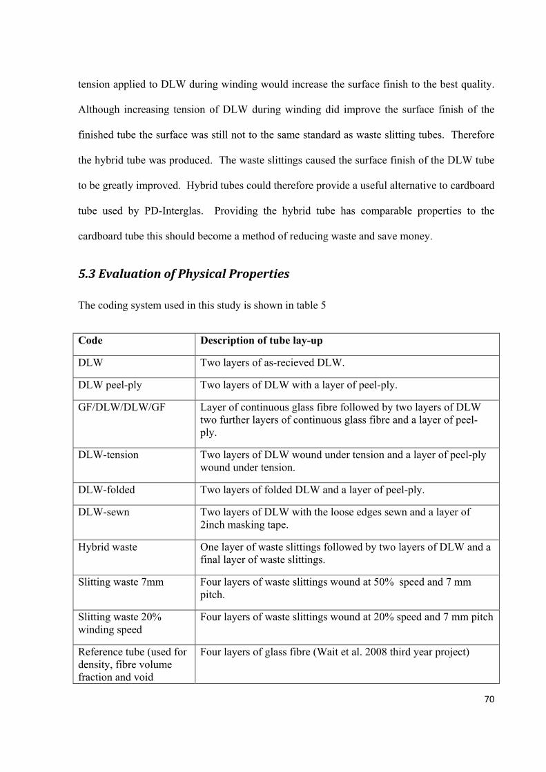
70
tension applied to DLW during winding would increase the surface finish to the best quality.
Although increasing tension of DLW during winding did improve the surface finish of the
finished tube the surface was still not to the same standard as waste slitting tubes. Therefore
the hybrid tube was produced. The waste slittings caused the surface finish of the DLW tube
to be greatly improved. Hybrid tubes could therefore provide a useful alternative to cardboard
tube used by PD-Interglas. Providing the hybrid tube has comparable properties to the
cardboard tube this should become a method of reducing waste and save money.
5.3 Evaluation of Physical Properties
The coding system used in this study is shown in table 5
Code Description of tube lay-up
DLW Two layers of as-recieved DLW.
DLW peel-ply Two layers of DLW with a layer of peel-ply.
GF/DLW/DLW/GF Layer of continuous glass fibre followed by two layers of DLW two further layers of continuous glass fibre and a layer of peel-ply.
DLW-tension Two layers of DLW wound under tension and a layer of peel-ply wound under tension.
DLW-folded Two layers of folded DLW and a layer of peel-ply.
DLW-sewn Two layers of DLW with the loose edges sewn and a layer of 2inch masking tape.
Hybrid waste One layer of waste slittings followed by two layers of DLW and a final layer of waste slittings.
Slitting waste 7mm Four layers of waste slittings wound at 50% speed and 7 mm pitch.
Slitting waste 20% winding speed
Four layers of waste slittings wound at 20% speed and 7 mm pitch
Reference tube (used for density, fibre volume fraction and void
Four layers of glass fibre (Wait et al. 2008 third year project)
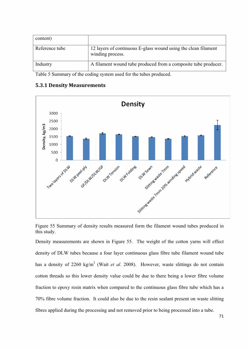
71
content)
Reference tube 12 layers of continuous E-glass wound using the clean filament winding process.
Industry A filament wound tube produced from a composite tube producer.
Table 5 Summary of the coding system used for the tubes produced.
5.3.1 Density Measurements
Figure 55 Summary of density results measured form the filament wound tubes produced in this study.
Density measurements are shown in Figure 55. The weight of the cotton yarns will effect
density of DLW tubes because a four layer continuous glass fibre tube filament wound tube
has a density of 2260 kg/m3 (Wait et al. 2008). However, waste slittings do not contain
cotton threads so this lower density value could be due to there being a lower fibre volume
fraction to epoxy resin matrix when compared to the continuous glass fibre tube which has a
70% fibre volume fraction. It could also be due to the resin sealant present on waste slitting
fibres applied during the processing and not removed prior to being processed into a tube.

72
5.3.2 Fibre Volume Fraction
Figure 56 Graph showing the results for the fibre volume fractions acquired from the resin burn off technique.
Percentage fibre volume fraction shown in Figure 56 again will be affected by cotton yarns
used to hold DLW together. During the resin burn-off method, the cotton yarns would have
burnt off with the resin matrix. This therefore has an effect on the results shown above by
increasing weight loss during burn-off that is attributed to the loss of resin. This will then
increase the volume fraction of matrix in the composite. This point is demonstrated above
with waste slitting samples and continuous glass fibres samples (not containing cotton yarns)
tend to have higher fibre volumes fractions. Ideally, cotton yarns would be taken into
consideration and also used in the equation. This, however, is more difficult to do because it
is difficult to find the quantity of cotton yarns in each sample. Other samples that have a high
fibre volume fraction such as DLW wound under tension could be attributed to peel-ply used

73
on the outer surface which did not burn-off during 6 hours in the furnace. Fibre volume
fraction of commercial composites ranges from 30-70% (Jones & DiBenedetto, 1993). This
shows the majority of waste fibre tubes produced using waste for PD-Interglas fit into this
commercial range although nearer the lower end (30%). This would make them unsuitable
for high performance composite applications which would be closer to the top 70% fibre
volume fraction.
5.3.3 Void Content
Figure 57 Graph showing the void contents gathered from the samples using the resin burn off technique.
Figure 57 shows void content found in each of the samples. The lowest void content was
found in the tensioned DLW sample which was also lower than the reference tube. This can
only be attributed to the tension applied to the DLW and peel-ply because the void content for
DLW with a layer of peel-ply not placed under tension had a much higher void content. The

74
effect of the tension causes fibres to be squeezed into all gaps and tension placed on the layers
below from above layers would cause resin to be pushed into areas where fibres have not been
fully impregnated. Also air gaps would be squeezed out so there is a lower void content once
cured this is also seen in the micrographs of sample 4. The hybrid sample showed one of the
next lowest void content values. During the winding of this tube, all the fabric was placed
under tension. Therefore, it can be concluded that to reduce void content tension needs to be
increase when winding waste fabric. Analysis of as-received waste slitting tube was not
completed because the deformation caused during the processing caused the tube to crack and
crumple on removal from the mandrel. Waste slitting samples have the highest void content.
This is due to issues with impregnating fabric which already had a layer of resin sealant
applied, so the resin does not permeate the glass fibres. Voids present will cause weaknesses
in the composite and this equates to lower mechanical properties. Voids act as areas of stress
concentration causing cracks to form and propagate through the matrix reducing the load
bearing potential of the matrix. This effect can be seen in the hoop tensile test conducted on
waste slitting samples explained in the mechanical testing section.
5.3.4 Microstructure Analysis
Microstructural images are displayed first and discussed in the text proceeding. Images 58,
59, 60 and 61 show the microstructure of waste slitting samples.

75
5.3.4.1 Waste Slittings‐7 mm Pitch
Figure 58 Micrograph showing the different layers of waste slittings with in the tube. There are large areas of resin rich content.
Figure 59 Micrograph showing an area within the tube with a higher concentrating of fibres. However there are still large areas with no fibres present. This image also shows the presence of voids within the sample.
5.3.4.2 Slitting Sample 2 with over Impregnation of the Fibres
Figure 60 Micrograph showing the different Figure 61 Micrograph showing an area in the
Silane sealant Resin rich area
Large resin rich areas Resin rich areasAreas of high fibre volume
Voids
Voids

76
layers of slitting waste within the tube and also shows the high concentration of resin within the sample between the layers of waste slittings.
bottom left where there is no resin. There is also an area at the top of the picture where the waste slitting layer appears to be damaged.
5.3.4.3 Direct Loom Waste
Figures 62-76 show images taken of the microstructure of tubes produced using DLW.
5.3.4.3.1 As‐Received DLW Tube
Figure 62 Micrograph showing that within the tube there are areas with high fibre content and it can be seen that not all the fibres are orientated in the same direction.
Figure 63 Micrograph within the same sample shows there are also large resin rich areas. The low void content seen in the images backs up the low void content shown in the burn off results.
Large resin rich area Area of high fibre content

77
5.3.4.3.2 Two Layers of DLW and a Layer of Peel‐Ply
Figure 64 Micrograph showing there are areas of high fibre content within the tube but there are some resin rich areas throughout the tube.
Figure 65 Micrograph showing not all the fibres are orientated in the same direction which could decrease the maximum strength of the tube but increase the strength in other directions
5.3.4.3.3 Glass Fibre/Direct Loom Waste/Direct Loom Waste/Glass Fibre
Figure 67 Micrograph showing the interface between the continuous glass fibre and the DLW. Some of the areas highlighted on the micrograph show a tight interface between the DLW and the glass fibre but there are areas
Figure 68 Micrograph showing the DLW within the continuous fibre layers. It is clear from the image that there are large resin rich areas. However image 84 shows the high fibre volume where the continuous glass fibres are
Close fibre interface
Resin rich interface
Resin rich area
Resin rich area
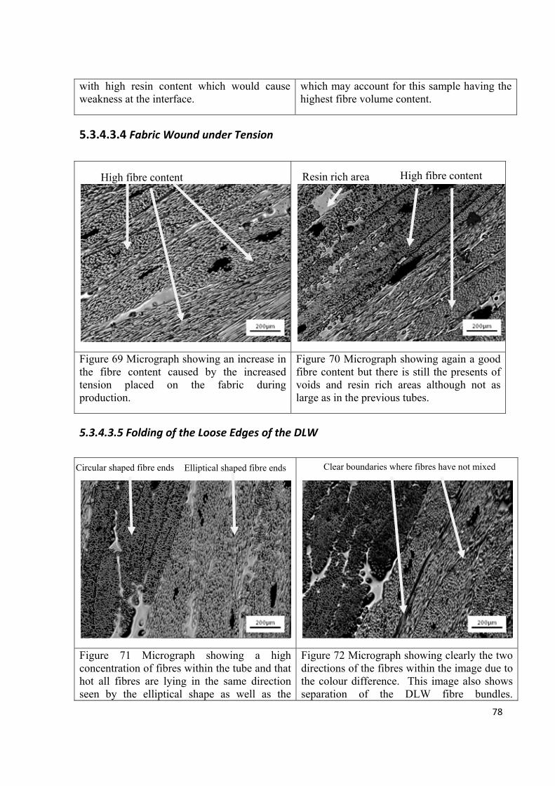
78
with high resin content which would cause weakness at the interface.
which may account for this sample having the highest fibre volume content.
5.3.4.3.4 Fabric Wound under Tension
Figure 69 Micrograph showing an increase in the fibre content caused by the increased tension placed on the fabric during production.
Figure 70 Micrograph showing again a good fibre content but there is still the presents of voids and resin rich areas although not as large as in the previous tubes.
5.3.4.3.5 Folding of the Loose Edges of the DLW
Figure 71 Micrograph showing a high concentration of fibres within the tube and that hot all fibres are lying in the same direction seen by the elliptical shape as well as the
Figure 72 Micrograph showing clearly the two directions of the fibres within the image due to the colour difference. This image also shows separation of the DLW fibre bundles.
Resin rich areaHigh fibre content High fibre content
Elliptical shaped fibre ends Circular shaped fibre ends Clear boundaries where fibres have not mixed

79
circular shape. Demonstrating the fibres do not always mix well throughout the layers.
5.3.4.3.6 Sewing Loose Edges of the Direct Loom Waste
Figure 73 Micrograph showing the high fibre content within the sewn DLW tube. There are some clear voids present however there does not appear to be any large resin rich areas.
Figure 74 Micrograph showing high fibre concentration with very small resin rich areas. This image also shows that the fibres are slightly better mixed between layers.
5.3.4.3.7 Hybrid Tube of Waste Slittings and Direct Loom Waste
Figure 75 Micrograph showing a section taken Figure 76 Micrograph showing the waste
Resin rich area
High fibre content Mixing of fibre tows
Resin rich area Resin rich areas at the interface between the DLW and waste slittings
Different direction of fibres Resin rich area

80
from the centre of the tube. Clear layers can be seen in the micrograph as well as large resin rich areas and voids.
slitiings used on the inside of the tube. There is a clear resin rich area between the two waste fabric types.
The results from the micrographs match with results from the fibre volume fraction and void
content measurements. All samples show areas of high fibre content. Fibres are generally
clumped together in original fibre tows used to weave the glass fibre fabric. Images also
show that fibres do not always align in the same direction this is seen by the shape of the
fibres in the images depending on the direction they can be circular or oval shaped. The
majority of DLW samples show this. This is caused by loose edges of DLW winding onto the
mandrel at different angles to the fabric held together by cotton yarns.
High fibre content is seen continuously in images of DLW wound under tension tube. This
corresponds with the fibre volume fraction results shown in Figure 56 and also the low void
content for that tube is demonstrated by the images. Folded DLW also shows a higher fibre
content than the as-received first two tubes. It also shows more variation in the direction of
fibres, this could result in strength in more than just the load bearing direction. Sewing DLW
essentially trapped loose edges of the fabric. This causes fibres to be orientated in roughly the
same direction. Orientation of fibres caused by sewing DLW could be useful in achieving
more predictable mechanical properties however this sample was not tested due to thickness
requirements for hoop tensile test and interlaminar shear strength tests. The hybrid waste
sample shows areas of high fibre content although not as good as the three tubes previously
mentioned also fibres are orientated in different directions. To improve quality and
predictability of the hybrid tube, the middle layers of DLW could be sewn before being
wound onto the mandrel holding loose edges of DLW place and giving a more uniform fibre

81
orientation which would improve the strength and stiffness of the composite in the direction
of the fibres (Papathanasiou et al. 1995). Hughes et al. (1980) demonstrated a composite
could reach theoretical strength values as predicted by the rule-of-mixture by maximising a
few variables and in particular the fibre orientation. For the maximum strength to be achieved
the composite must be highly ordered with fibre axes parallel, and in the direction of applied
stress. Although aligning fibres in a longitudinal direction across the tube will weaken the
hoop tensile strength, the bending stiffness across the tube will be maximised. This is an
important criteria for the cardboard tubes because during use they have to support the weight
of the fabric when supported at the edges.
Tubes with large resin rich areas such as those seen in sample-1 and sample-2 (as-received
DLW) are likely to demonstrate lower mechanical properties due to these areas resulting in
stress concentrations which will cause the composite to fail sooner. Results from the
interlaminar shear stress concentration for sample-2 shown below demonstrate this sample has
the lowest short-beam strength.
The hybrid waste sample shows clear lines of resin separating the fibre sections which again
will result in high stress concentrations in these areas and allow crack growth to propagate
through the sample much more rapidly resulting in lower mechanical properties which is
again demonstrated by the lowered ILSS value.

82
5.3.5 Thickness Measurements
Figure 77 “Spider” graph demonstrating the thickness of the hybrid waste tube over 8 given points around the circumference. Each ring sample was 15mm wide.
Through-thickness of the tube was only carried out on the hybrid waste sample because it had
visibly the best quality surface finish and most even cross-sectional thickness; therefore, it
was appropriate to see if the thickness was as even throughout the tube. As can be seen from
Figure 77, the through-thickness of the hybrid waste tube shows little variation throughout the
tube at the 8 points selected. Table 6 shows the standard deviation for average thickness
variation across the length of the tube is 0.32 mm. Although this demonstrates it is possible
to produce a tube with desired industrial standard thickness variations, the surface quality of
the tube has to be improved to be comparable to the surface quality of cardboard tubes used
by PD-Interglas. One potential method is to machine the surface on a lathe. However, this
would require extra processing and inevitably increase the cost of producing the tube.

83
Another possible method that could be used is to over impregnate the surface of the tube and
leave on a rotating mandrel to cure. This might cause increase resin usage but would leave
the tube with a very smooth resin surface that also had an even surface thickness.
Longitudinal thickness variation Thickness (mm)
Average thickness of hoop 1 3.691
Average thickness of hoop 2 4.28
Average thickness of hoop 3 4.534
Average thickness of hoop 4 4.012
Average thickness of hoop 5 3.782
Average thickness of hoop 6 3.894
Average 4.032
SD 0.32
Table 6 Summary of the data attained for average thickness of each tube and then the average thickness and standard deviation of the whole hybrid waste tube.

84
5.4 Evaluation of Mechanical Properties
5.4.1Interlaminar Shear Strength
Figure 78 Graph showing interlaminar strength of the DLW samples tested.
ILSS is used to assess the bond strength between different layers of the composite ring. This
test was performed on thicker specimens because they were too thick for hoop tensile tests
(samples must be smaller than 2 mm thick). Results from DLW samples were compared to a
12-layer continuous glass fibre/epoxy resin tube and one tube made in industry. Figure 78
shows DLW wound under tension achieved the highest ILSS which might be expected
because the tension placed on the fibres squeezes them into gaps in the layer below; fibres are
also spread out more and with fewer resin rich areas in the sample which would promote
crack propagation. Fibres bridging across the layers can act as crack arrestors by either

85
stopping the crack growth or redirect the crack in a different direction. One of the most
promising results seen from this particular experiment is that nearly all the tubes produced
with the exception of tube-2 (DLW peel-ply) can achieve ILSS values at least half of the
industrial standard tube produced using virgin materials. A study by ÇeÇen et al. (2008) use
a short-beam shear strength test to determine the ILSS of composite samples produced using
unidirectional and biaxial glass fibre fabrics. They showed that unidirectional glass fabric in
the loading direction achieves a value of 26.07 ± 0.79 MPa with a fibre volume fraction of
33.7% ± 1.3%. This demonstrated that the tubes produced using DLW have an ILSS
comparable to low fibre volume unidirectional fabrics. One problem with using this test is it
focuses mainly on the strength at the interface between the fibre and matrix as opposed to the
fibre strength this is also shown in a study by Sideridis and Pandopoulos (2004). To make the
results more comparable Figure 79 normalised ILSS to fibre volume fraction found previously
from the resin burn-off technique.

86
Figure 79 Graph showing interlaminar strength normalised to fibre volume fraction.
Figure 79 shows that when normalised to fibre volume fraction (70%), DLW tubes produced
can reach equivalent values as the tube provided by an industrial partner. However, there
would be a potential issue with producing a tube with a high enough fibre volume fraction
with a similar thickness to an industrial tube. If processing was developed to produce a tube
with a higher waste fibre content to thickness ratio the tubes produced would be of high
enough strength to replaced composites used in low load bearing applications. Although the
hybrid tube does not have as high a value for ILSS, the values are still creditable and the
surface quality and low through-thickness variation means it is more likely that this tube
could be used by PD-Interglas to replace their cardboard tubes.

87
5.4.2 Hoop Tensile Strength
The hoop tensile test was carried out on waste slitting samples as mentioned previously. In
Figure 80, results were compared to a 4-layer continuous glass filament wound tube. Both
waste slitting tubes had a considerably lower tensile strength than continuous glass fibre
tubes. This is likely to be due to the lower fibre volume fraction in the waste slitting tube and
higher void content present in these tubes shown in micrograph images in Figures 58, 59, 60
and 61. However, when normalised to fibre volume fraction, waste slittings still demonstrate
a much lower hoop tensile strength. The image analysis section of waste slitting tubes, shows
there are large areas of resin throughout the composite tube. These areas will be areas of
weakness in the tube. Also, large voids are seen in both samples caused by the difficulty
impregnating fibres during the filament winding process. These again act as stress
concentration areas and are likely to be crack initiation sites which can join to cause the
composite to fail.
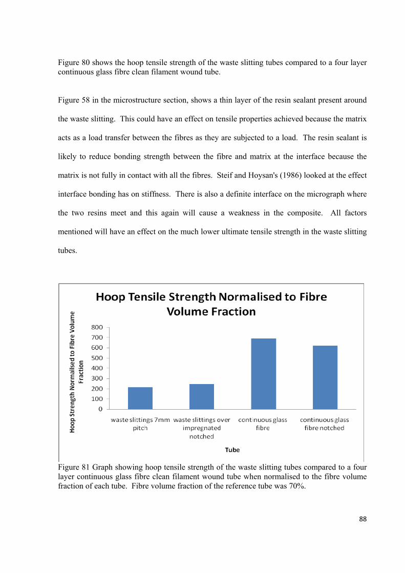
88
Figure 80 shows the hoop tensile strength of the waste slitting tubes compared to a four layer continuous glass fibre clean filament wound tube.
Figure 58 in the microstructure section, shows a thin layer of the resin sealant present around
the waste slitting. This could have an effect on tensile properties achieved because the matrix
acts as a load transfer between the fibres as they are subjected to a load. The resin sealant is
likely to reduce bonding strength between the fibre and matrix at the interface because the
matrix is not fully in contact with all the fibres. Steif and Hoysan's (1986) looked at the effect
interface bonding has on stiffness. There is also a definite interface on the micrograph where
the two resins meet and this again will cause a weakness in the composite. All factors
mentioned will have an effect on the much lower ultimate tensile strength in the waste slitting
tubes.
Figure 81 Graph showing hoop tensile strength of the waste slitting tubes compared to a four layer continuous glass fibre clean filament wound tube when normalised to the fibre volume fraction of each tube. Fibre volume fraction of the reference tube was 70%.

89
5.4.3 Lateral Compression
Results from lateral compression tests shown in Figure 82 demonstrate the hybrid tube has a
much higher compressive strength than the cardboard tube. Reinforcing glass fibres have a
significantly higher tensile strength than the cellulose-based cardboard tubes. After the load
was removed, it was observed the cardboard tube had deformed permanently. The hybrid
waste tube on the other hand maintains its circular circumference for a longer period of
loading. Once the load is removed the tube moves back to almost its original cylindrical
shape. This demonstrates the weaknesses of using cardboard tubes compared to the hybrid
tube not only because better strength can be obtained but also the hybrid tubes do not undergo
significant deformation before failure
Failure mechanisms between both tubes are different with glass fibre tubes failing at the
contact points with the compression plates. The cardboard on the other hand shows
delamination at areas just off the centre of the loading points and then large failure points
between the delamination and the edges of the tube. This could possibly be due to the
difference in the diameter/thickness ratio as described by Gupta and Abbas, (2000). They
found four possible failure lines in glass fibre/epoxy tubes during compression which are
dependent on the diameter/thickness ratio.

90
Figure 82 Graph showing the results obtained for the lateral compression experiment completed on the hybrid waste sample and the cardboard tubes used by PDI.
5.5 Life Cycle Analysis (LCA)
LCA results for waste fibre tubes produced using filament winding have been compared to a
continuous glass fibre/epoxy tube produced using conventional filament winding system and
the clean filament winding system. Table 7 shows the effect input and output data collected
from all tubes has on the following environmental impacts: acidification potential which is the
decrease in pH of rain water caused by air pollutants. Eutrophication potential which is the
enrichment of nutrients in a certain place caused by air pollutants, waste water and
fertilization in agriculture. Freshwater aquatic ecotoxicity potential, global warming
potential, human toxicity potential, marine aquatic ecotoxicity potential, ozone layer depletion
potential, photochemical ozone creation potential and terrestric ecotoxicity potential. Each
potential impact was measured against an equivalent emission i.e. acidification potential was
measured in kilograms of SO2 equivalent emitted. To aid the comparison between different

91
methods and tubes produced the resulting percentage change of each environmental impact
potential was compared to the conventional filament winding impact potential is shown in
brackets beneath the raw data of each category.
Table 7 Raw potential environmental impact data
Winding Method
LCA Parameter Conventional CFW
R-CFW:
WS
R-CFW:
DLW
R-CFW:
Hybrid
Acidification potential
(kg SO2 – Equivalent) 0.52
0.46
(-11%)
0.39
(-25%)
0.43
(-17%)
0.44
(-15%)
Eutrophication potential
(kg Phosphate – Equivalent)
0.04 0.03
(-25%)
0.02
(-50%)
0.03
(-25%)
0.03
(-25%)
Freshwater aquatic ecotoxicity potential
(kg DCB – Equivalent) 0.13
0.12
(-7%)
0.11
(-15%)
0.11
(-15%)
0.12
(-7%)
Global warming potential
(kg CO2 – Equivalent) 115.76
101.27
(-12%)
73.19
(-36%)
88.85
(-23%)
92.02
(-20%)
Human toxicity potential
(kg DCB – Equivalent) 5.50
5.08
(-7%)
4.86
(-11%)
5.00
(-9%)
5.03
(-8%)
Marine aquatic ecotoxicity potential
(kg DCB – Equivalent) 4457.76
3932.64
(-11%)
3517.4
(-21%)
4090.5
(-8%)
4206.4
(-5%)
Ozone layer depletion potential
(kg R11 – Equivalent) 1.08E-05
1.08E-05
(0%)
1.02E-05
(-5%)
1.02E-05
(-5%)
1.02E-05
(-5%)
Photochemical Ozone creation potential
(kg Ethene – Equivalent) 0.05
0.04
(-20%)
0.03
(-40%)
0.03
(-40%)
0.02
(-60%)

92
Terrestric ecotoxicity potential
(kg DCB – Equivalent) 0.08
0.06
(-25%)
0.05
(-37)
0.07
(-12%)
0.08
(0%)
Average percentage Reduction (%)
(compared to conventional filament winding)
- 13 26 17 16
(N.B. Data written in italics inside the brackets refers to the percentage decrease of each environmental impact potential in comparison to conventional filament winding.)
Results have been put into radar plots so environmental impact of each tube can be compared
to the conventional filament winding method used to produce a continuous glass fibre tube.
Figure 83 Radar plot comparing the environmental impact potentials of conventional and recycled-clean filament winding (waste slittings). The axis headings in this Figure are identical to those defined Table 7.
It can be seen in Figure 83 and Table 7, a tube produced using just waste slittings has a lower
environmental impact than using continuous virgin glass fibres with both conventional
filament winding and clean filament winding. There is an average overall reduction on
environmental impact of the tube by around 26% compared to the glass fibre tube produced
using the conventional system with some of the major reductions to eutrophication potential

93
(50% reduction), reduction in global warming potential (36%), 40% reduction to
photochemical ozone creation potential and 37% to terrestric ecotoxicity potential. The
reduction in environmental impact of this tube is lowest because using waste glass fibres has
no impact in terms of the impact of glass fibre production. Therefore, if mechanical
properties of the tube can be increased by increasing the resin impregnation of the fibres and
the fibre volume increased this tube could have a significant impact on the practical uses of
these tubes.
Figure 84 Radar plot comparing the environmental impact potentials of conventional and recycled-clean filament winding (DLW).
Results from Figure 84 and Table 7 give the environmental impact of the tube produced using
the clean filament winding with DLW. There is an average reduction of 17% from the
conventional system used and as can be seen on Figure 84 there are some effects that are
lower than the clean filament winding system with virgin glass fibre but there are some
impacts which are higher such as terrestric ecotoxicity potential and marine aquatic

94
ecotoxicity potential which can only be contributed to the increase quantity of resin required
to produce DLW tubes. To reduce the impact there would need to be far less resin used in the
production of a DLW tube. This could be achieved by applying tension to DLW so excess
resin is squeezed out from the first layer and helps to impregnate the second layer on top
therefore reducing the amount of resin needed. Results for the hybrid tube shown in Table 7
and Figure 85 show the average environmental impact reduction is 16% of the conventional
filament winding method. Although this tube has the highest impact of all waste tubes there
is still a reduced environmental impact when compared to the conventional filament winding
technique. This demonstrates the environmental impact of producing glass fibre because
when this is removed from the LCA data and replaced with recycled fibres the environmental
impact is reduced in all cases.
Figure 85 Radar plot comparing the environmental impact potentials of conventional and recycled-clean filament winding (Hybrid).

95
6. Conclusion
This study was a feasibility study to investigate possibilities of using waste glass fibres to
produce filament wound tubes with a view to replace cardboard tubes. In particular, this
study investigated reusing waste glass fibres generated at a weaving company (PD-Interglas).
Two types of waste were studied: waste slittings and DLW. Both were used in the clean
filament winding process to produce filament wound tubes that could be then used by PD-
Interglas to replace existing cardboard tubes used within their company.
It was found it was possible to insert DLW and waste slittings directly into the existing clean
filament winding system with little alterations made to the material or equipment. The DLW
tubes produced showed comparable mechanical properties to industrial and reference
continuous glass fibre tubes when normalised to fibre volume fraction. They also
demonstrated a low void content showing effective impregnation of fibres can be achieved
using the clean filament winding process. One main disadvantage of DLW tubes is the poor
surface finish caused by loose edges of the fabric. However, this can be improved by
applying tension to the fabric.
Waste slitting tubes produced have a much better surface finish than DLW tubes but they
demonstrate lower mechanical properties caused by higher void content. Void content could
be lowered by maximising impregnation of the fibres.
Combining both types of waste in a hybrid tube the composite produced demonstrates better
mechanical properties than the waste slittings alone and has a much better surface finish than
DLW tubes. When compared to the compression strength of the cardboard tube the hybrid
tube shows much higher compressive strength. This hybrid tube could be used by PDI to

96
replace the cardboard tubes that they use within their company which sustain damage easily
and have to be replaced regularly.
If waste fibre tubes were used instead of cardboard tubes this might save costs for the
company, reducing the amount of waste disposal needed and reducing the cost of replacing
damaged cardboard tubes.
The results obtained from the LCA demonstrate that tubes produced with waste glass fibres
using the clean filament winding process can reduce the environmental impact of tube
production due mainly to the fact that the glass fibres are reused and therefore no extra
processing is required to make them.

97
7. Future work
A rotating mandrel in the oven would ensure there was an even spread of resin throughout the
cured composite tube. A rotating mandrel designed to fit in the existing oven would increase
the accuracy of results and quality of the surface on the finished tube.
Pressure burst experiments carried out on the hybrid tube would gather more information on
mechanical properties of the tube. Pressure burst experiment would involve sealing the tubes
at both ends and filling with water until ultimate failure of the tube occurred. Pressure burst
experiments would allow the whole tube to be tested to ultimate failure.
A trial tube should be produced for PD-Interglas to incorporate into their manufacturing
process so the tube could be monitored in a real working situation exposed to all the impacts
and loads that the tube will undergo in service. This tube would be a tube either 1350 mm or
1150 mm (to take fabric at 127 mm and 1000 mm) in length with an internal diameter of 152
mm so it fits onto the existing 150 mm standard chuck. The tube is supported at either end
and must carry 800 m of 300 gram per square meter fabric. The tube would be produced with
the hybrid sandwich structure.
Another aspect that could be considered for future work would be to look into making the
whole tube more environmentally friendly. As the glass is recycled the environmental impact
of the reinforcing fibres is already low however improvements could be made by altering the
resin matrix used or limiting waste resin by reducing the quantity of resin used in each tube.
The use of a different resin matrix will reduce the environmental impact of the tubes and also
making the working environment safer for workers producing the tube.

98
8. References Allred, R. E. and Busselle, L. D. (2000), Tertiary Recycling of Automotive Plastics and Composites, Journal of Thermoplastic Composite Materials, 13: 92-101. Astrom, B. T. (1997), Manufacturing of Polymer Composites, Chapman and Hall, London, 242: 401–405. Bartl,A., Hackl, A., Mihalyi, B., Wistuba, M and Marini, I. (2005), Recycling of Fibre Materials. Process Safety and Environmental Protection, 83(B4): 351–358. Benne`s, J., Alzuaga, S., Chabe´, P., Morain, G., Che´rioux, F., Manceau, J.-F., Bastien, F. (2006), Action of Low Frequency Vibration on Liquid Droplets and Particles. Ultrasonics 44: 497–502. Bernasconi, A., Davoli, P., Basile, A. Filippi, A. (2007), Effect of Fibre Orientation on the Fatigue Behaviour of a Short Glass Fibre Reinforced Polyamide-6. International Journal of Fatigue 29: 199–208. Brearley, W. and Holloway, D.G. (1963), Physics and Chemistry of Glass. 4: 69-75. Cai, Y, Seyam, A. M. & Kim, Y. K. (2007), Formation of Fibrewebs from Staple Fibres with Controlled Fibre Orientation using Electrostatic Forces: Theoretical Analysis. Journal of Engineered Fabrics and Fibres 2 (2): 17-24. Cecen V, Sarikanat M, Yildiz H, Tavman, I. H. (2008), Comparison of Mechanical Properties of Epoxy Composites Reinforced with Stitched Glass and Carbon Fabrics: Characterization of Mechanical Anisotropy in Composites and Investigation on the Interaction between Fiber and Epoxy Matrix. Polymer Composites 29 (8): 840-853. Chirdona, W. M., O’Brien, W. J., Robertson, R. E. (2006), Diffuse Reflectance of Short-Fibre-Reinforced Composites Aligned by an Electric Field. Dental Materials 22: 57–62. Chu, J and Sullivan, J. L. (1996), Recyclability of a Continuous E-Glass Fiber Reinforced Polycarbonate Composite. Polymer Composites 17 (4): 556-567. Clarke, J and Harris, J. (2001), Controlled Orientation of Short Fibre Reinforcement for Anisotropic Performance of Rubber Compounds. Plastics, Rubber and Composites 30 (9): 406-415. Conroy, A., Halliwell, S., Reynolds, T. (2006), Composite Recycling in the Construction Industry. Composites: Part A 37: 1216–1222. Cox, H. L., (1952), Br. J. Appl. Phys 55: 39.

99
Cunliffe, A. M., Jones, N., Williams, P. T. (2003), Recycling of Fibre-Reinforced Polymeric Waste by Pyrolysis: Thermo-Gravimetric and Bench-Scale Investigations. Anal. Appl. Pyrolysis 70: 315-338. Cunliffe, A. M., Williams, P. T. (2003), Characterisation of Products from the Recycling of Glass Fibre Reinforced Polyester Waste by Pyrolysis. Fuel 82: 2223–2230. Dang, W. R., Kubouchi, M., Yamamoto, S. R.( 2002) Polymer 43. de Brito, M.P, Van Der Laan, E. A. and Irion, B.D. (2007), Extended Producer Responsibility
in the Aviation Sector.
de Marco, I., Caballero, B., Torres, A., Laresgoiti, F., Chomo´n, J. and Cabrero, A. (2002), Recycling Polymeric Waste by Means of Pyrolysis. J Chem Technol Biotechnol 77: 817-824. Demura K, Ohama Y and Satoh T. (1995), Properties of Artificial Woods using FRP Powder’, Disposal and Recycling of Organic and Polymeric Construction Materials, Proceedings of the International Rilem Workshop, Tokyo, 26–28. Dolan. C. W., Galloway. T. L,. Tsunemori. A,. (1997), Prestressed Glued-Laminated Timber Beam- Pilot Study. Journal of composites for construction 1 (1): 10-16.
Ehrig, R.J. (1992), Plastics Recycling: Products and Processes, Carl Hanser Verlag, Germany. Fara, S. and Pavan, A (2004), Fibre Orientation Effects on the Fracture of Short Fibre Polymer Composites: On The Existence of a Critical Fibre Orientation on Varying Internal Material Variables. Journal of Materials Science 39: 3619–3628. Flemming T, Kress G, Flemming M (1996), A New Aligned Short-Carbon-Fiber-Reinforced Thermoplastic Prepreg Advanced Composite Materials 5 (2): 151-159. Forslind K. H. (2005), Implementing Extended Producer Responsibility: the Case of Sweden's Car Scrapping Scheme. Journal of Cleaner Production 13 (6): 619-629. Fukuda, H and Kawata. K., (1974), Fibre. Sci. Tecnol 7: 207. Guell, D.C., Graham, A.L., (1996), Improved Mechanical Properties in Hydrodynamically Aligned, Short-Fiber Composite Materials. Journal of Composite Materials 30 (1): 2-12. Gupta, N. K and Abbas, H. (2000), Int. J. Imp. Eng. 24: 329.
Haake. A, Dual. J. (2004), Positioning of Small Particles by an Ultrasound Field Excited by
Surface Waves. Ultrasonics 42: 75–80.
100
Harper, L.T., Turner, T.A., Martin, J.R.B., Warrior, N.A., (2009), Fiber Alignment in Directed Carbon Fiber Preforms - A Feasibility Study. Journal of Composite Materials 43 (1): 57-74. Hughes, J. D. H., Morley H, Jackson, E. E. (1980), Aligned Carbon-Fiber Composite which Approaches Theoretical Strength. Journal of Physics D-Applied Physics 13 (6): 921-936. Hurd, M. K. (1997), High-Performance Plywoods for Concrete Forming. Impervious overlays and coatings leave smoother concrete. Hou, Y. MS Thesis (2001), University of Massachusetts at Dartmouth. Jiang, G., Pickering, S.J., Lester, E., Turner, T.A., Wong, K.H., Warrior, N. (2008), Characterisation of Carbon Fibres Recycled from Carbon Fibre/Epoxy Resin Composites using Supercritical n-propanol, Composites Science and Technology 69 (2): 192-198. Jiang, G., Pickering, S. J., Walker, G.S., Wong, K.H., Rudd, C.D. (2008), Surface Characterisation of Carbon Fibre Recycled using Fluidised Bed. Applied Surface Science 254: 2588–2593. Jin, S., Tiefel, T. H and R. Wolfe, R. (1992), Directionally-Conductive, Optically-Transparent Composites by Magnetic Alignment IEEE Transactions on Magnetics 28 (5): 2211-2213.
Jody, B. J., Pomykala, J. A., Daniels, E. J and Greminger, J. L. (2004), A Process to Recover Carbon Fibers from Polymer-Matrix Composites in End-of-Life Vehicles Overview ELV Recycling 43-47 Kacir, L, Narkis, M, Ishai, O (1975), Orientated Short Glass-Fiber Composites .1. Preperation and Statistical-analysis of Aligned Fiber Mats. Polymer Engineering and Science 15 (7): 525-531. Kacir, L, Narkis, M, Ishai, O (1975), Orientated Short Glass-Fiber Composites .2. Analysis of Parameters Controlling Fiber-Glycerine Orientation Process. Polymer Engineering and Science 15 (7): 532-537. Kelly, A. and Tyson, W. R., (1956), High Strength Materialsed. Zackay (New York: Wiley) Kennerley, J. R., Kelly, R. M., Fenwick, N. J., Pickering, S. J and Rudd, C. D. (1998), The Characterization and Reuse of Glass Fibre Recycled from Scrap Composites by the Action of a Fluidized Bed Process. Composites Part A 29A: 839-845. Liu Y, Meng L, Huang Y, Du J. (2004), Recycling of Carbon/Epoxy Composites. J Appl Polym Sci 94 (5): 1912-1916. Pandita, S. D., Smith, S., S-Gale, N., Paget, M., Allen, J. M., Fernando, G. F. (2007), “Clean” Filament Winding: A New Manufacturing Process

101
Palermo, J. (1992), Advanced Composites: Design, Materials, and Processing Technologies, ASM International, Materials Park, Ohio, 255–256. Pannkoke K, Oethe M, Busse J. (1998), Efficient Prepreg Recycling at Low Temperatures Conference Information: 8th International Cryogenics Materials Conference. Cryogenics 38 (1): 155-159.
Papathanasiou, T. D and Guell, D. C. editors (1997), Flow-Induced Alignments in Composite Materials. Woodhead publishing limited. Cambridge. Papathanasiou, T. D., Ingber, M. S., Guell, D. C. (1995), Stiffness Enhancement in Aligned, Short-Fibre Composites: A Computational and Experimental Investigation Composites Science and Technology 54: l-9. Pickering, S. J., Kelly, R. M., Kennerley, J. R., Rudd, C. D. and Fenwick, N. J. (2000), Fluidized-bed Process for the Recovery of Glass Fibres from Scrap Thermoset Composites, Composites Science and Technology 60(4): 509–523. Rathje, W., & Murphy, C. (1992). “Five Major Myths About Garbage and Why They’re Wrong,” http://www2.plasticsresource.com Reinhard, D. L. (1992), Spe Antec Tech. Papers 38: 1545. Rettenmaier, S., (1988), European patent EP313603. Sanomura, W., Kawamura, M. (2003), Fibre Orientation Control of Short-Fibre Reinforced Thermoplastics by Ram Extrusion. Polymer Composites 24 (5): 587-596.
Sarasua, J. R., Pouyet, J. (1997), Recycling Effects on Microstructure and Mechanical Behaviour of PEEK Short Carbon-Fibre Composites. Journal of Materials Science 32: 533-536. Schinner, G. Brandt, J and Richter, H. (1996), Recycling Carbon-Fiber-Reinforced Thermoplastic Composites. Journal of Thermoplastic Composite Materials 9; 239. Sideridis E, Papadopoulos, G. A. (2004), Short-Beam and Three-Point-Bending Tests for the Study of Shear and Flexural Properties in Unidirectional-Fiber-Reinforced Epoxy Composites. Journal of Applied Polymer Science 93 (1): 63-74. Steif, P. S., Hoysan, S. F. (1986), On Load-Transfer Between Imperfectly Bonded Constituents. Mechanics of Materials 5 (4): 375-382. Stewart, J., Minchin, R. E., Jaselskis, E. J., Dayal, V and Smith, G. (2004), Potential Construction Applications for Thermoset Composite Scrap Material Journal of Construction Engineering and Management 130 (2): 199-205

102
Torres, A., de Marco, I., Caballero, B. M., Laresgoiti, M. F., Legarreta, J. A., Cabrero, M. A., Chomo´n , M. J. (2000), GC-MS Analysis of the Liquid Products Obtained in the Pyrolysis of Fibre-Glass Polyester Sheet Moulding Compound. Journal of Analytical and Applied Pyrolysis 58–59:189–203 Torres, A., de Marco, I., Caballero, B. M., Laresgoiti, M. F., Legarreta, J. A., Cabrero, M. A., Gonza´lez, A., Chomo´n, M. J., Gondra, K. (2000), Recycling by Pyrolysis of Thermoset Composites: Characteristics of the Liquid and Gaseous Fuels Obtained Fuel 79: 897–902. Williams, P. T., Cunliffe, A and Jones, N. (2005), Recovery of Value-Added Products from the Pyrolytic Recycling of Glass-Fibre-Reinforced Composite Plastic Waste. Journal of the Energy Institute78 (2): 51-61. Woodside AR, Woodward WDH and Jellie JH. (2003), Highway Engineering Material Tests at Ulster University, [Project funded with Landfill Tax Credits by the RMC Environment Fund (RMCEF)]. Yamashita, S., Hatta, H., Sugano, T And Murayama, K. (1989), Fibre Orientation Control of Short Fibre Composites: Experiment. Journal of Composite Materials 23: 32-41. Yin, Y., Binner, G. P., Cross, T. E. (1994), The Oxidation Behaviour of Carbon Fibres J. Mater. Sci. 29 (8): 2250-2254. Yip, H. L. H., Pickering, S. J and Rudd, C. D. (2002), Characterisation of Carbon Fibres Recycled from Scrap Composites using Fluidised Bed Process. Plastics, Rubber and Composites 31 (6): 278- 282.
Yuyan, L., Linghui, M., Yudong, H and Lixun, L (2006), Journal of Reinforced Plastics and Composites 25 (14): 1525–1533. Zhang, T., Evans, J. R. G and Bevis, M. J. (1997), Control of Fibre Orientation in Injection Moulded Ceramic Composites. Composites Part A 28A: 339-346.
1. http://www.glulam.co.uk/framesetGlulam.htm
DIRECTIVE 2000/76/EC OF THE EUROPEAN PARLIAMENT AND OF THE COUNCIL of 4 December 2000 on the incineration of waste Official Journal of the European Communities L 332/91-111 DIRECTIVE 2006/12/EC OF THE EUROPEAN PARLIAMENT AND OF THE COUNCIL of 5 April 2006 on waste Official Journal of the European Union L 114/9-21

103
Council Directive 1999/31/EC of 26 April 1999on the landfill of waste Official Journal of the European Union L182/1-19 DIRECTIVE 2002/96/EC OF THE EUROPEAN PARLIAMENT AND OF THE COUNCIL of 27 January 2003 on waste electrical and electronic equipment (WEEE) Official Journal of the European Union L 37/24-38 Directive 2000/53/EC of the European Parliament and of the Council of 18 September 2000 on end-of-life vehicles, [2000] OJ L 269/34. professional engineering- recycling law curbs of composites29 June 2005 13 Directive 75/442/EEC on waste, (1975) OJ L 194/39 and (1991) O J L 78/32. Council Regulation (EEC) No 259/93 of 1 February 1993 on the supervision and control of shipments of waste within, into and out of the European Community, as amended [1993] OJ L 30/1.

104
Appendix
1. Recycling thermoplastic matrixes
Two common methods used to recycle thermoplastics are: milling and grinding and melting
and re-moulding. Grinding and milling of the FRP produces ground down recyclate which
can then be used in a different composite. Recyclate from the grinding process has been used
to reinforce injection moulded components with the results of the new recycled product
showing properties comparable to virgin injection moulded compounds (Chu and Sullivan,
1996): Schinner et al. (1996). It has been shown glass filled polypropylene thermoplastics
FRPs composites have recycling possibilities (Reinhard, 1992). Chu and Sullivan (1996)
found the new component retained 73% of its original tensile strength after reprocessing. Chu
and Sullivan (1996) investigated extrusion compression and compression moulded
components. The results showed a decrease in the tensile strength in recycled components
from both processes although impact strength in the compression moulded component
increased. Disadvantages of this technique are cutting causes fibres to fray and wear. The
shortening of fibres during grinding disrupts the continuous structure and so reduces the
strength of the fibre. Also cutting the composite can cause wearing of the cutting equipment
resulting in replacement of tools and increase cost.
Schinner et al. (1996) used the melting and re-moulding technique and found very little
change in the material properties such as the flexural strength, flexural modulus and percent
elongation when compared to similar laminates processed just once. However Sarasua &
Pouyet (1997) looked at the effects of recycling on the microstructure and mechanical
properties of injection moulded PEEK and short-carbon fibre composites. Their findings
showed the more times fibres were reprocessed; there was an increase in damage to the fibres
resulting in a subsequent decrease in fibre length and in turn a reduction in tensile strength,

105
impact strength and Young’s modulus. Although there is an obvious reduction in mechanical
properties these recycled composites could be suitable for some applications detailed in
section 3.4 and reduce composites going to landfill or incineration. For this method to be
effective there must be an effective scheme to collect, sort and purify composites before
recycling so new FRP can be produced with similar properties to the original material.
2. Size reduction recycling of composites
Size reduction is a process by which a composite component (uncured prepregs) undergoes a
series of cutting and milling processes into a recyclate which can be of different sizes. This
can then be reused as a filler with virgin constitutes in a new FRP component. The
disadvantages are the fibres become damaged and are reduced in size so lose their continuous
structure. Astrom (1997) found during grinding fibre length is shortened and there is a
decrease in the molecular weight of the resin. They also found a reduction in the interfacial
bonding between fibre and resin. Pannkoke et al. (1998), ground uncured prepreg tapes and
fabric waste and manufactured composites by pressing, autoclave pressing or scale cut
recyclates (two layered laminates). They found tensile modulus of the ground material was
nearly independent of manufacturing process and was three times that of just epoxy resin.
Superior stiffness was found in the scale cut material to the mill cut materials used for the
pressing. This demonstrates that modulus depends on the scale size. Broken fibres in the
components produced form recycled fibres might make them unsuitable for structural
applications due to broken fibres acting as notches which increase crack initiation at lower
loads thus failure could occur at lower tensile strength than predicted if using the rule of
mixtures. However bending strength of the ground recyclate composite was better than
tensile strength and suggested that it might be useful for use in sandwich structures.

106
3. Incineration with energy recovery
Incineration with energy recovery and composting should only be considered if all
alternatives are deemed inappropriate because toxic fumes generated contribute to global
warming and damaging the environment. Given that polymers are made from oil, it would
make since that they produce a good fuel sources when burnt. FRPs have a high calorific
value therefore incineration with energy recovery is a viable option. Incinerator operators
will usually charge more for FRP waste because of the high calorific content and toxic
emissions given off during incineration. Electricity can be produced from energy recovery
but this is not the primary concern of the incinerators (Conroy et al. 2006).
4. Criteria for new components produced using recycled fibres
The composite produced should improve properties of the new component or at least match
properties of the material used previously it should not just act as a filler giving no benefit to
the component or a novel disposal method. The composite should not require extras added to
the mix in order to remove any deficiencies caused by inclusion of recycled material. The
composite should not make the component more difficult to recycle. The new product should
not pose any environmental or health and safety problems when in use. The new component
should be made to last a suitably long time and also be cost effective to the manufacturer
5. Definition of Peel-ply
Peel-ply is usually a woven fabric material made of fibreglass, polyester, or heat-set nylon
that can be applied directly to the surface of a prepreg lay-up or in this case the wetted surface
of the uncured tube.
6. Procedure for fibre volume fraction
107
Crucibles were removed for the furnace after being allowed to cool to room temperature.
Crucibles were then weighted again with the sample. The crucible weight was taken away
from the sample and crucible measurement after burn-off to leave the amount of the sample
left after being in the furnace. This new value of the sample weight was taken away from the
sample weight prior to burn-off to leave the mass of the resin lost during burn-off. From this
it is possible to calculate the volume of sample made up of fibre and resin.
7. Procedure for Hoop Tensile Test
Tubes were measured into 20 mm sample rings and cut using a hand saw. Tensile tests were
completed on five sample rings taken from each waste slitting tube. The test was carried out
using Zwick 1484 at a displacement of 2 mm/min. Before each sample was tested five
measurements were taken of width and thickness of each sample. The sample was loaded
until failure. The second tube produced was cut for the tensile test as mentioned but had 3.2
mm radius holes drilled into each side of the ring to create a notch and was repeated directly
on the opposite side. Width and thickness of the sample between the two notches was
measured.
8. Definition of Life cycle analysis
LCA is the study of current and potential environmental impacts of a product during its whole
lifetime. This takes into account the raw material acquisition, the production, use and end of
life management for example recycling, incineration, or disposal. For an LCA to be
completed the following items must be completed: (i) collection of all relevant inputs and
outputs of production system; (ii) evaluation of potential environmental impacts associated
with the inputs and outputs; and (iii) interpretation of results presented by the inventory
analysis and impact assessment phases in relation to the objectives of the study. It is

108
important that an LCA was completed for this study because the tubes produced using
recycled glass fibre need to have less of an environmental impact than tubes produces using
the conventional filament winding and virgin glass fibres.
9. Power values for filament winding process.
Values for power were acquired from the power required to run the filament winding machine
and oven. Specifically these were calculated by using the power required for the filament
winding machine to run (5 kWh AC motor) which took 2 hours to complete the required
winding. As a result, 10 kWh or 36 MJ of electricity was consumed. The use of the oven to
‘cure’ the sample which used 6 heating elements each of which individually consumed 2.3
kWh. The furnace was also equipped with an air circulating motor which consumed 0.7 kWh.
As a result, for each method the curing cycle consumed 94 kWh or 339.3 MJ.
10. Requirements of Glass Fibre tubes to replace Cardboard tubes
Requirements for the tubes produced are as follows: the tube must have a higher wear
resistance and longer working life than existing cardboard tubes so they do not require
replacing. The new tubes must be able to withstand a higher compressive force than the
cardboard tubes so that as the woven glass is wound onto the tubes they maintain their shape.
Flexural strength must also be high because the tubes will be transported by the two ends of
the tube leaving the middle section with the weight of the glass fabric unsupported. Finally,
hoop tensile strength must be high enough to withstand the clamps pushing against the inner
walls when being held in position on machines or being transported around the factory.

109

110
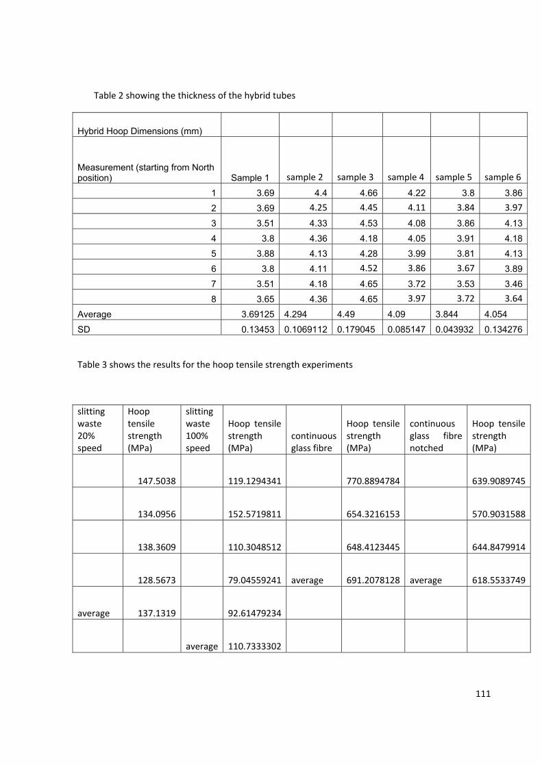
111
Table 2 showing the thickness of the hybrid tubes
Hybrid Hoop Dimensions (mm)
Measurement (starting from North position) Sample 1 sample 2 sample 3 sample 4 sample 5 sample 6
1 3.69 4.4 4.66 4.22 3.8 3.86
2 3.69 4.25 4.45 4.11 3.84 3.97
3 3.51 4.33 4.53 4.08 3.86 4.13
4 3.8 4.36 4.18 4.05 3.91 4.185 3.88 4.13 4.28 3.99 3.81 4.13
6 3.8 4.11 4.52 3.86 3.67 3.897 3.51 4.18 4.65 3.72 3.53 3.46
8 3.65 4.36 4.65 3.97 3.72 3.64
Average 3.69125 4.294 4.49 4.09 3.844 4.054
SD 0.13453 0.1069112 0.179045 0.085147 0.043932 0.134276
Table 3 shows the results for the hoop tensile strength experiments
slitting waste 20% speed
Hoop tensile strength (MPa)
slitting waste 100% speed
Hoop tensile strength (MPa)
continuous glass fibre
Hoop tensile strength (MPa)
continuous glass fibre notched
Hoop tensile strength (MPa)
147.5038 119.1294341 770.8894784 639.9089745
134.0956 152.5719811 654.3216153 570.9031588
138.3609 110.3048512 648.4123445 644.8479914
128.5673 79.04559241 average 691.2078128 average 618.5533749
average 137.1319 92.61479234
average 110.7333302

112

113
Table 5 shows the results from the lateral compression strength experiment
cardboard tubes
Compressive Strength (MPa)
hybrid waste tube
Compressive Strength (MPa)
1 62.73274 1 627.31632 71.20227 2 588.16983 67.77516 3 554.78086 62.43295 4 517.05037 76.555 5 468.3812
average 68.139624 551.13968Stdv 5.960950228 61.6409296

University of Birmingham Research Archive
e-theses repository This unpublished thesis/dissertation is copyright of the author and/or third parties. The intellectual property rights of the author or third parties in respect of this work are as defined by The Copyright Designs and Patents Act 1988 or as modified by any successor legislation. Any use made of information contained in this thesis/dissertation must be in accordance with that legislation and must be properly acknowledged. Further distribution or reproduction in any format is prohibited without the permission of the copyright holder.