Embed Size (px)
Citation preview
The Revolution of Train Control System in JAPAN
Masayuki Matsumoto East Japan Railway Company
2-2-2 Yoyogi, Shibuya-ku, Tokyo 151-8578, JAPAN, Tel : +81-3-5334-1245, Fax : +81-3-5334-1246 E-mail : [email protected]
Abstract
The following report will introduce train control systems applied in railway lines in Japan. The report also will show that train control systems have been developed and these are classified four levels from “Level 0” to “Level 3”. We call these train control systems “East Japan Train Control system” (EJTC).
“Level 0” system, the Automatic Train Stop device (ATS-S), was introduced into Japanese National Railways (JNR) to prevent train collision. This system has been replacing with Pattern type ATS (ATS-P); “Level 1” system. ATS-P was developed to eliminate the weaknesses of the ATS-S.
The Automatic Train Control (ATC) system was originally developed to support safe, super-high speed railway transportation utilizing Japan’s Shinkansen and introduced into conventional commuter lines to shorten the train interval. However it was difficult to realize efficient operations in high-density lines due to limitations of existing ATC technology. Then the D-ATC system (Digital and Decentralized ATC) had been developed as “Level 2” system using ADS technology. In D-ATC system, the device on each train autonomously calculates permitted speed of each train. This system is introduced to Keihn-tohoku Line as D-ATC and Shinkansen Line as DS-ATC (Digital Communication & Control for Shinkansen-ATC).
Recent remarkable progress in the field of information technology makes possible a new train control system where train itself detects its location and communicates with other trains through radio transmission. Therefore, we have been developing the “Level 3” train control system called ATACS (Advanced Train Administration and Communications System). ATACS is the new train control system using information technology and ADS technology. ATACS prototype system is testing at Senseki Line in Tohoku district for practical use.
1. Introduction
In the beginnings of railways there was no signaling system. A station attendant showed the signal of go or stop by gestures. But a man often makes mistakes, and train accidents happened. Although drivers operate trains in accordance with signals, there is a potential for rear-end and head-on collisions, and other accidents if signals are ignored or misread by drivers. Signaling system prevent these accidents. Automatic Train Stop (ATS) devices prevent these types of accidents by stopping the train automatically when a signal is showing stop. If the driver ignores the warning from ATS, on-board equipment automatically brakes and stops the train.
In the transportation and safety area, operations have become very efficient as a result of the systematizing of train operations, and introduction of new automatic train stop devices (ATS-P). By using digital information from a transponder, ATS-P transmits information about signal aspects and the distance to the next stop signal from the trackside to the train and uses this information to generate a train speed-checking pattern. ATS-P then evaluates whether the driving speed is appropriate and automatically applies the brakes when the situation is judged to be dangerous.
Since the missing of a signal can lead to a serious accident, it became necessary to install devices that display the permitted speed and apply braking automatically in accordance with the emerging instruction on high speed line sections and high density lines. This device is known as an Automatic Train Control system (ATC). ATC was first introduced on the Tokaido Shinkansen because it was thought that conventional signals were difficult to see safely at high speeds. Introduction of ATC has enabled safe operations even when drivers misread the signal aspect and the level of safety has been heightened
5990-7803-8963-8/05/$20.00 ©2005 IEEE
compared to the point control type ATS as it employs a continuous control system. ATC is obligatory on line sections with cab signal block systems. The ATC on-ground equipment transmits signal currents for controlling speeds in track circuits and the on-board ATC equipment receives these signals. It shows signals on-board and has a function for automatically controlling braking according to signal aspects.
However, since ATC devices are based on technology existing at the time the Tokaido Shinkansen was built, they present many problems including an inability to increase the number of trains. The following is an analysis of the ideal form of ATC as a train control system. The only thing necessary to stop a train without running into the preceding train is to know “the distance to the position where the train must stop.” The information essential for this is “the accurate position of the train” and “the position at which the train should stop.” By reanalyzing the actual objective of ATC, the basic function of the new train control system emerged. In other words, the groundside devices should only transmit information on the position at which the train must stop and the train should recognize its own position and calculate the distance to the stopping point transmitted from the ground. The train then should take curves, gradients and such into consideration and apply appropriate braking at the necessary time. This is the principle of the new train control system (D-ATC) that we have newly developed.
The present signaling system has a long history and provides a fairly high degree of safety and at the same time helps maintain a certain level of traffic utilization, but on the other hand it has some problems. Remarkable progress has been made recently in the field of integrating mobile communication technology and computer technology. It is hoped that the introduction of mobile communication technology and computer technology into the railway control system will help minimize the wayside facilities and make flexible repairs possible, thereby solving the problem of high cost. Accordingly, efforts are being made to develop a new railway control system called ATACS, for which information technology (digital radio and computer technology) is utilized and a new framework of wayside and on-board functions has been adopted.
The report will introduce the train control systems, technology used in this systems and future developments.
2. Development of train control systems in Japan
The first passenger railway transport system began
to operate in 1830 between Liverpool and Manchester in The United Kingdom. Afterward a signaling system was adopted to improve safety and to cope with the increase of traffic volume.
Progress of signaling technology has been achieved by electronic communication technology. In 1841, it was installed at both ends of a tunnel of North Midland Railway to make it possible to communicate between both ends to prevent the entry of more than one train in the tunnel at the same time. That is the beginning of fixed block signaling, which prevents train collisions. The track circuit, which detects a train position, was invented in 1872. All of these devices have been contributing to improve safety. Although some modifications were adopted after their invention, present signaling systems are based on principles invented in the 19th century.
Various tests were carried out starting in 1921 during the pre-war Japanese Government Railways era. A cab warning device, a predecessor to ATS, was in use on the Yamanote and Keihin Tohoku Lines from December 1954. Despite this, a major train collision killing over 100 people still occurred on 3 May 1962 at Mikawashima Station on the Joban Line. This was just after studies on a new cab warning device had started, and the accident led to the decision to introduce the ATS system - a system that adds a stop function to the on-board warning device. The resultant ATS was introduced on all sections of Japanese National Railways (JNR) in April 1966. This device was called ATS-S.
Development of the ATS-P was pursued as a result of a derailment at Hirano Station on the Kansai Main Line in 1973. It entered service for the first time in March 1987 at some stations (Kusatsu, Kyoto, Osaka and Nishi-Akashi) on the narrow-gauge Tokaido and Sanyo Main Lines, and on express trains (hauled by electric locomotive) after another derailment at Nishi-Akashi Station on the Sanyo Main Line in 1984.
In September 1988, JR East established the first phase of a construction plan that called for introduction of ATS-P on the Chuo, Joban, and other Lines. With the opening of the Keiyo Line on 1 December 1988, ATS-P was in use on an entire section for the first time. A further train collision at Higashi-Nakano Station on 5 December 1988 led to the speeding up of the planned introduction, and sections where the system was to be introduced were also expanded (Chuo Line in 1989 and others since). Use of it has currently spread to the principal line
600
sections in the Tokyo Metropolitan Area, the Yamagata Shinkansen and the Akita Shinkansen.
Concurrent with the opening of the Tokyo Olympics, operation of the Tokaido Shinkansen Line commenced between Tokyo and Osaka in October 1964. As Shinkansen trains run at super-high speeds, the cab signal system that sends speed signals to the driving cab has been used since operation of the Tokaido Shinkansen Line commenced. The ATC system is used to automatically control train speeds in accordance with those speed signals. The ATC is an important piece of equipment that ensures safe, stable high-speed transportation. In this ATC, the central ATC logic device calculates permitted speed in each blocking section and controls speed of all trains.
ATC was introduced on narrow-gauge lines when through operations started between the JNR Joban Line and the Chiyoda subway line in 1971. In 1981, it was introduced on the Yamanote Line, Keihin Tohoku Line and other sections as a safety measure after repeated rear-end collisions at Funabashi, Nippori and other JNR stations. The Joban Line ATC had been renewed in 1999 and it uses single-level brake control rather than the conventional multi-level brake control.
JR East decided in 2000 to develop and introduce a new digitally operated D-ATC and DS-ATC taking into account the facts that the present ATC needs to be renewed. In the D-ATC, the central logic device calculates each position to which a train can move safely, and sends the information on positions to all trains. On each train, the on-board equipment calculates an appropriate braking pattern with the information, and controls velocity of the train. That is, in the new system, the device on each train autonomously calculates permitted speed of the train. DS-ATC was introduced to Hachinohe Shinkansen in 2002.12 and D-ATC was introduced to the Keihin-Tohoku Line in 2003.12. and in the near future DS-ATC will be introduced to the Tohoku and Joetsu Shinkansen.
JR East is currently developing a train control system that uses wireless communications, known as ATACS. Present train control is performed in the following manner. Train location is detected by wayside signaling facilities, and according to train location, train control signals are displayed to prevent collisions between trains. However, this control way requires an enormous number of facilities. That means large construction and maintenance costs. Recent remarkable progress in the field of information technology makes possible a new train control system where a train itself detects its location and
communicates with other trains through radio transmission.
Therefore, we have been developing the new train control system called ATACS. ATACS is the new train control system using information technology and ADS technology. The prototype system was tested last year on the Senseki Line in Tohoku. 3. Classification of train control system
As described earlier, a train control systems have been developed by the Japanese National Railways and the East Japan Railway. As a result, accidents of collisions of trains, rear-end collisions and so on have decreased remarkably.
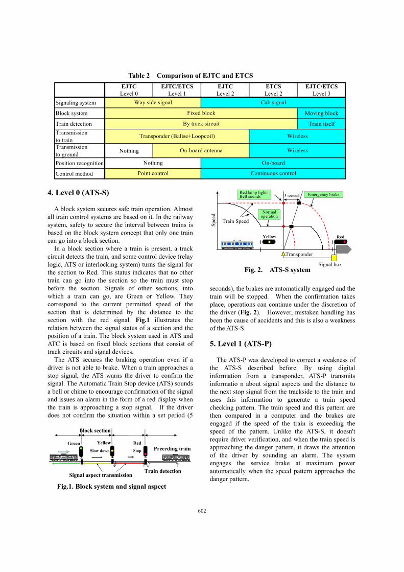
We classify train control systems into 4 levels, with the overall name East Japan Train Control system (EJTC). Each level’s system is used on appropriate lines according to characteristic of the railway (Table 1).
Also, for these systems, the level is determined by fixed block system or moving block system, train detection by the track circuit or train position recognition with an on-board system, information transmission to on-board via the track circuit or by radio, and so on. These are shown in Table 2 comparing with the characteristic of ETCS in Europe.
Table 1 Classification of EJTC
Level EJTC
Level 0
ATS-S : It sounds a bell or chime to encourage confirmation ofthe signal and issues an alarm in the form of a red display whenthe train is approaching a stop signal. If the driver does notconfirm the situation within a set period (5 seconds), the brakesare automatically engaged and the train will be stopped.
Level 1
ATS-P : It doesn't require driver verification, and when the trainspeed is approaching the danger speed pattern, it draws theattention of the driver by sounding an alarm. The systemengages the service brake at maximum power automaticallywhen the speed pattern is on the verge of the danger pattern.
Level 2
D-ATC : The ground side should only transmit information onthe position at which the train must stop and the train shouldrecognize its own position and calculate the distance to thestopping point transmitted from the ground. The train thenshould take the roadway curves, gradients and such intoconsideration and apply appropriate braking.
Level 3
ATACS : The ground controller in each area has such functionsas train location, interval control, switching control, levelcrossing control and security for maintenance work. The radiobase station exchanges information with the on-board computer.The on-board computer controls brake according to control datasupplied by the ground controller and also transmits data on thetrain location to the ground controller through the on-boardmobile radio station.
601
4. Level 0 (ATS-S)
A block system secures safe train operation. Almost all train control systems are based on it. In the railway system, safety to secure the interval between trains is based on the block system concept that only one train can go into a block section.
In a block section where a train is present, a track circuit detects the train, and some control device (relay logic, ATS or interlocking system) turns the signal for the section to Red. This status indicates that no other train can go into the section so the train must stop before the section. Signals of other sections, into which a train can go, are Green or Yellow. They correspond to the current permitted speed of the section that is determined by the distance to the section with the red signal. Fig.1 illustrates the relation between the signal status of a section and the position of a train. The block system used in ATS and ATC is based on fixed block sections that consist of track circuits and signal devices.
The ATS secures the braking operation even if a driver is not able to brake. When a train approaches a stop signal, the ATS warns the driver to confirm the signal. The Automatic Train Stop device (ATS) sounds a bell or chime to encourage confirmation of the signal and issues an alarm in the form of a red display when the train is approaching a stop signal. If the driver does not confirm the situation within a set period (5
seconds), the brakes are automatically engaged and the train will be stopped. When the confirmation takes place, operations can continue under the discretion of the driver (Fig. 2). However, mistaken handling has been the cause of accidents and this is also a weakness of the ATS-S. 5. Level 1 (ATS-P)
The ATS-P was developed to correct a weakness of the ATS-S described before. By using digital information from a transponder, ATS-P transmits informatio n about signal aspects and the distance to the next stop signal from the trackside to the train and uses this information to generate a train speed checking pattern. The train speed and this pattern are then compared in a computer and the brakes are engaged if the speed of the train is exceeding the speed of the pattern. Unlike the ATS-S, it doesn't require driver verification, and when the train speed is approaching the danger pattern, it draws the attention of the driver by sounding an alarm. The system engages the service brake at maximum power automatically when the speed pattern approaches the danger pattern.
EJTC EJTC/ETCS EJTC ETCS EJTC/ETCSLevel 0 Level 1 Level 2 Level 2 Level 3
Signaling system
Block system Moving block
Train detection Train itselfTransmissionto trainTransmissionto ground Nothing
Position recognition
Control method Point control
Wireless
Continuous control
Transponder (Balise+Loopcoil) Wireless
Nothing On-board
By track sircuit
On-board antenna
Way side signal
Fixed block
Cab signal
Table 2 Comparison of EJTC and ETCS
RedYellowGreenPreceding trainSlow down Stop
block section
Train detectionSignal aspect transmission
Fig.1. Block system and signal aspect
Train SpeedSp
eed
5 seconds
Normal operation
Emergency brakeRed lamp lightsBell sounds
Transponder
Signal box
RedYellow
Fig. 2. ATS-S system
602

Fig. 3 shows the overall structure and the speed pattern and installation standards for transponders in the case of block signals.
The ATS-P has several functions. It prevents signal violation accidents for entry/exit block signals, shunting signals related to main track and calling-on signals. And it prevents accidents resulting from exceeding speed limits on turnouts, curves and down gradients. Moreover ATS-P increases signal aspect efficiency for high braking performance trains. High-, mid- and low-deceleration train information is transmitted from on-board to the trackside. This data is evaluated at the trackside and signals are controlled accordingly.
The train ID and other information can be sent to the trackside from on-board. This information can be used for operational control of trains, control of level crossings according to train speed, automatic public announcements at stations, etc.
When the driver is operating the train at a level equal to or below the speed pattern in the figure, the brakes are not applied. The brakes are applied only when the train operation exceeds the speed pattern.
To enable a train stopped ahead of the final transponder to operate after the signal changes to Caution or Clear, the speed pattern up to the signal is set to a maximum of 10 km/h. In addition, if the train passes the transponder at a stop signal, "Stop immediately (service)" is received and the maximum service brake is applied immediately and a speed limit of 15 km/h is applied for 80 m from the transponder in the forward direction. 6. Level 2 (D-ATC) 6.1. Conventional ATC
Fig. 4 illustrates train speed control of a conventional ATC system. In the ATC system, a signal
device that indicates permitted speed is located in the driver’s cab on trains, and it continuously receives information on the permitted speed transmitted from ground equipment.
The central ATC logic device sends ATC signals to track circuits. The ATC signal is information on the permitted speed, and at the same time, it is used as a train detection signal. The logic device can determine the section on which a train is present by monitoring the level of received ATC signal power because the wheels of the train short the track circuits. Boundaries of the track circuits and the pattern of permitted speed are designed in order to sustain train’s headway, which is necessary for train traffic control.
In the ATC system, the central ATC logic device takes charge of most of the train interval control, and on-board equipment only controls the braking of the train according to instructions from the central device.
The conventional ATC improves security and traffic efficiency but some problems still remain as listed below.
(a) The braking control pattern is not smooth at the boundary of a section, therefore the time of a braking operation tends to increase, driving operability is bad and the train interval cannot be shortened.
(b) The improvement of rolling stock performance does not improve the efficiency of transportation because the headway mainly depends on the permitted speed and the boundary position of the section.
(e) Most equipment is placed in the central part of the system and many cables are laid from the central device to the track circuits, which is costly. 6.2. D-ATC
An interval control is another concept of train control. In this control method, a system recognizes the distance between a train and a preceding train and ensures safe train operation by controlling the speed of
Spee
d
Permitted Speed Pattern
Warning of approaching to
pattern
Service brake
RedYellow
Encoder
Transponder
Normal operation
Fig.3. ATS-P system
90 65 45 0456590 65 45 04565
Spee
d
Permitted Speed
Train Speed
ATC-Device
Fig.4. Conventional ATC system
603

these trains. In order to realize this interval control, various new functions are required such as accurate train location and high-speed communication between trains and ground equipment.
In this manner, the major difference between the D-ATC system and the conventional ATC is that the D-ATC system is an on-board intelligent system. The new system differs from the conventional system in that each train autonomously calculates the appropriate permitted speed with information on the stop position transmitted from the central ATC logic device (Fig. 5).
The following are the characteristics of the new system.
(a) High-density traffic is possible as brakes are continuously engaged up to the stop point using pattern control.
(b) The ground facilities can be slimmed down and made inexpensively due to the use of general information equipment and a decentralized system.
(c) The system contains the flexibility of being able to shorten the train headway without changing ground equipment when rolling stock performance is improved.
(d) Improved operability can be obtained by indicating the train usage on routes to driver.
Consequently, the cost of the D-ATC system is less than that of the conventional ATC and has also enabled the train headway to be shortened to two minutes from the two minutes and thirty seconds of the conventional ATC systems. Also, construction costs can be lowered by twenty percent compared to traditional methods.
Further, both reliability and safety have been improved and a figure of 10-12 has been secured for the failure rate of the danger side as SIL 4 level.
East Japan Railway Company(JR East), has developed a new Shinkansen D-ATC that utilizes
digital communications and control, officially called DS-ATC. Reductions in arrival times and intervals between trains can be realized as well. DS-ATC is expected to contribute to safer, smother Shinkansen transportation. 7. Level 3 (ATACS) 7.1. System configuration
The ideal form of interval control consisting of
trains knowing each other’s positions through wireless communication between them also becomes possible. JR East is currently developing this type of a train control system that uses wireless communications known as “ATACS.” ATACS is the new train control system using information technology. The objectives of ATACS are as follows: (a) Cost reduction
Reducing construction and maintenance costs (b) Flexibility for system changes
No need of improvement work when train speeds are increased or headways shortened
(c) Improved safety Closed-loop control and security for maintenance work A section of railway line is divided into several
control areas, in each of which a ground controller and a radio base station are set up. The ground controller in each area has functions such as train location, interval control, switching control, level crossing control and security for maintenance work. The radio base station exchanges information with the on-board computer. As the appropriate interval between stations is determined according to the service area covered by radio transmissions, several base stations may be linked to the same ground controller.
The on-board computer controls brakes according to control data supplied by the ground controller and also transmits data on the train location to the ground controller through the on-board mobile radio station. The first step in the control procedure is to determine the accurate location of a train as measured by the on-board computer. The initial position of a train is input when the train passes balise put up on the system boundary across which trains enter or exit. Subsequently, the on-board computer keeps track of the train location by detecting its speed and processing the speed data. The train location is corrected when the train passes a balise set at appropriate points (Fig. 6).
Digital control signal
Transmitter device
ATC-LAN
TrainPreceding train
Logical controller
Digital train detect signal
3. Its train position recognition
4.brake pattern occurrence
5.Brake control1.Train detect
2.Stop position transmission
Fig. 5. D-ATC system
604

The train location as detected by the system is structured into the identification number of the ground controller in the relevant control area, the virtual blocks into which the control area is divided, and the position within the relevant track block, and these data are processed by the wayside and on-board computer. Radio base stations are set up at intervals of three kilometers or so based on the reach of radio transmissions. To prevent radio interference between adjoining radio base stations, waves of four different frequencies are used alternately. For on-board operation, the frequency is so chosen as to be receivable by the radio base station in each area. Each base station needs to communicate with several trains running in its area, assuming that it communicates with each train on a one-second cycle. Accordingly, one second is divided into several time slots. An error may occur in the data during the transmission. Accordingly, the space diversity system and the Reed-Solomon code for forward error correction are adopted to improve the quality of transmission. 7.2. Function
ATACS has many functions. Here, we describe the main functions, train interval control and level crossing control.
The functions of ATACS are as follows: (a) Train interval control
The train speed is controlled by calculating the permissible speed from the limited movement authority of the train, instead of directly indicating the speed signal as in the present system.
The base procedure for train interval control is as follows. First, the train location is transmitted by radio to the ground controller. Next, the ground controller determines the location to which that train can be permitted to move (limited movement
authority) on the basis of data on the train location and route of each train in the control area, and transmits the findings to each train. Further, the on-board computer determines the permissible distance of running based on the limited movement authority and the present train location. With braking performance and track conditions (gradient, curve, speed limit, etc.) taken into consideration, the on-board unit generates a brake intervention curve which can cause the train to stop at the limit of this permissible distance of running and applies the brakes. (b) Level crossing control
In ATACS, level crossings are controlled on the basis of an exchange of data between trains and the ground controller.
For adjusting train approach warning duration, the train calculates estimated time of arrival at the level crossing according to train performance and speed and sends it to the ground controller by radio. The ground controller activates the level crossing according to this. After activating the level crossing protection, the ground controller sends to the train, and the train recalculates the brake intervention curve. If the level crossing protection does not become active, the train stops before the level crossing. (c) Other function
There are other functions such as security for maintenance work, switching control, bi-directional distance control and temporary speed limits. 7.3. ADS technologies of ATACS In ATACS, the ground system is decentralized, and each device is connected by a network. Each on-board system does brake control autonomously by using the limited movement authority that it has been given in transmitted information by the ground controller. The ground system is divided into a central control of traffic system and a train control system, and it is the composition which gives autonomously to each equipment. As a result, it prevents a failure of some equipment from affecting the whole system. And it is possible to build a system step-by-step. When a radio base station breaks down, an adjacent radio base station backs it up autonomously, and operation of the system is continued automatically.
8. Conclusion
The above described the applications conditions of information technology within JNR and JR East and
Digital radio communication
1. Train position recognition
2. Train position transmission
4. brake pattern occurrence
5. Brake control
Logical controller and Radio station
3. Its train position recognition
Fig. 6. ATACS system
605

particularly focused on the train control system. In the case of the control system, “the development of information and communications technology” and the “heightening of transport needs” both progressed as critical features of the era and the history of this development was emphasized in this paper. The construction of a completely new train control system was also described.
JR East has developed the D-ATC and DS-ATC, and is moving forward with the introduction of the system. Shinkansen and conventional railways operating with this digital ATC will provide passengers safer, more comfortable travel. Moreover, since the new ATC is of an on-board control type, its entire composition is more compact, which allows for reductions in construction and maintenance costs. We, at JR East, are confident that D-ATC and DS-ATC will become a standard ATC for railway systems and intend to recommend its introduction in various fields.
We have already finished control run tests of prototype ATACS. The results of the test show this system is developed enough to put into actual service. New train control systems will be developed in the 21st century by applying the latest information and control technology in place of the conventional signaling system applied for over 100 years.
Future autonomous train control systems will consist of an on-board system only, without a ground system. Each train will communicate directly with others and each train will control its own brakes autonomously, based on information from other trains. ADS technology, information technology and communication technology is the key to realize the future train control system.
References [1] K.Mori, S.Miyamoto, K.Ihara, “Proposal of Autonomous Decentralization Concept”, IEEJ-C, Vol.104-C, No.12,
Dec.1984 [2] K.Mori, “Autonomous Decentralized Systems : Concept, Data Field Architecture and Future Trends”, ISADS1993, Kawasaki, Japan [3] T.Kobayashi, O.Iba, H.Ebine, S.Aoyagi, “Advanced Train Administration and Communication System Based on ADS Technologies”, ISADS1999, Tokyo, Japan, Mar.1999 [4] Signal Engineering Association of Japan, “Development of Railway Signal”, 1980 [5] M.Matsumoto, “Electric Railway”, Morikita ,Apr.1999 [6] M.Matsumoto, “The Revolution of Railway System by Using Advanced Information Technology”, IWADS2000, Chengdu, China, Sep.2000 [7] M.Matsumoto, A.Hosokawa, S.Kitamura, D.Watanabe, A.Kawabata, “The New ATC System with an Autonomous Speed Control with On-board Equipment”, ISADS2001, Dallas, USA, Mar.2001 [8] M.Matsumoto, A.Hashimoto, K.Tashiro, D.Watanabe, “Dependable Automatic Train Control System with Digitalized Track Signal”, DSNS2001, Goeteborg, SWEDEN, Jul.2001 [9] M.Matsumoto, A.Hosokawa, S.Kitamura, D.Watanabe, A.Kawabata, “Development of the Autonomous Decentralized Train Control System”, IEICE Trans.Commun, Vol.E No.10, Oct.2001 [10] M.Matsumoto, Y.Mizukami, A.Hashimoto, K.Yagi, T.Ikehira, T.Kawano, “New ATC System with Digital Transmission and On-board Intelligence”, WCRR2001, Koeln, Germany, Nov.2001 [11] M.Matsumoto, T.Tsurumaki, T.Shigeta, K.Tashiro, D.Watanabe, “The New ATC System with an Autonomous Speed Control with On-Board Equipment”, PRDC2001, Seoul, Korea, Dec.2001 [12] M.Matsumoto, T.Shigeta, K.Tashiro, N.Amiya, “Automatic Train Control System Based on Communication Links”, DSNS2002, Washington,DC, USA, Jun.2002 [13] M.Matsumoto, T.Tsurumaki, D.Watanabe, K.Mori, “Modeling of Train Control System and a Proposed Method of Assurance Evaluation”, ADSN2002, Vienna, AUSTRIA, Jul.2002
606


![Military Revolution in Early Modern Japan [Stavros 2013]](https://img.pdfslide.net/doc/110x75/577c7c7a1a28abe0549ac097/military-revolution-in-early-modern-japan-stavros-2013.jpg)