Embed Size (px)
Citation preview

The Search for Baby Nanotubes (SFBN)September 30, 11 am, Berry Aud.
See www.letu.edu/chemphys and the fall seminar link for a complete listing of all seminars.


Target Surface Temperature and
In situ Detection of Carbon Nanotubes
During Production in a Laser Produced Plume
Gary DeBoerLeTourneau University
Longview, TX
NASA Johnson Space CenterThermal Branch
Structures and Mechanics DivisionEngineering Directorate
Summer, 2004

Some carbon allotropes
graphite
diamond
C60
nanotube

Tensile Strength Comparison of Engineering Materials, GPa
1.5
3.4
4.7
50
0 10 20 30 40 50 60
Stainless Steel
Aramid (Kevlar)
Carbon Fiber
CarbonNanotubes
Ref: Brad Files
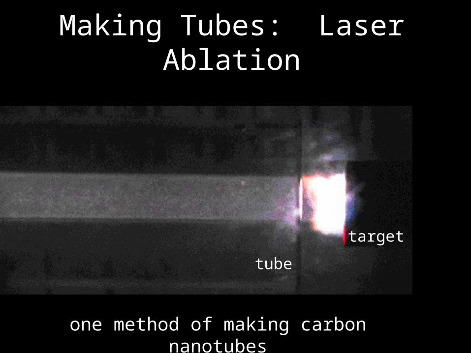
Making Tubes: Laser Ablation
target
tube
one method of making carbon nanotubes

SEM of Nanotube Bundleshttp://mmptdpublic.jsc.nasa.gov/jscnano/Photo%20Gallery.htm

TEM carbon nanotube ropes
smalley.rice.edu

Experimental method
For LIF studies of:
C2 and Ni


Nickel and C2
Laser Induced Fluorescence (LIF)Lifetimes Ni atom: millisecondsC2: 100 microseconds
DeBoer et al.J. Appl. Phys. A., 89, 5760 (2001)
0 500 1000 1500 2000
1mm From Target2mm From Target3mm From Target (x10)
Pump-Probe Delay ( s)
473.0 473.1 473.2 473.3 473.4 473.5 473.6 473.7 473.8
Wavelength (nm)

Co
Laser Induced Luminescence (LIL)
Lifetimes:Co atom millisecondsCarbon seconds
Geohegan et al.Appl. Phys. Letts., Vol. 76 (3) p 182 (2000)
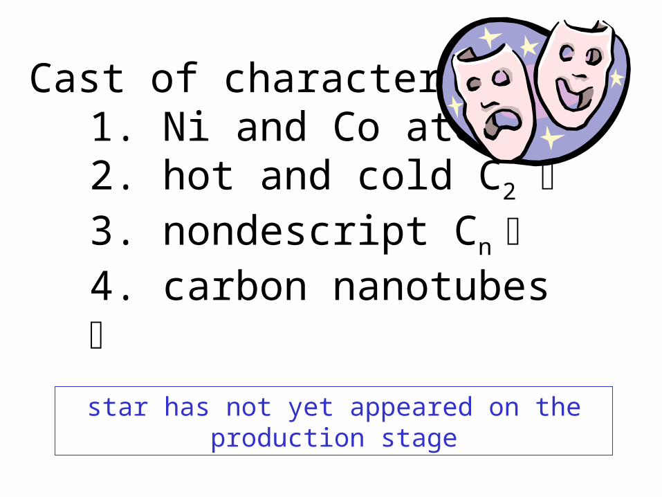
Cast of characters1. Ni and Co atoms2. hot and cold C2 3. nondescript Cn 4. carbon nanotubes
star has not yet appeared on the production stage

What is under?

What is under?

What is under?

What is under? Saturn Rocket Park!

Saturn Rocket Park

Saturn Rocket Park

Designs and goals to uncover the nanotube picture
1. Surface temperature measurement• incorporate into modeling projects
• correlate measured surface temperatures to other measured values
2. Detect nanotubes during their formation by absorption
• chemical mechanisms
• plume dynamics
• feasibility of use as production control feedback

Y-Tube designHow do we measure target surface
temperature?1. collect emission with fiber optic2. disperse with spectrometer3. record with a CCD
fiber optic focusing lens
target
ablation lasers
black body emission
1 inch tube
translatable stage
Surface Temperature

Optical setup for surface temperature experiment using y-tube

Laser 1Gr
532 nm
Laser 2IR
1064 nm
ICCD
DDG
650 700 750 800 850 900 950 1000
3456789
wavelength (nm)

0
5000
10000
15000
20000
300 400 500 600 700 800 900 1000
Black Body Radiation
1473 K
2000 K
2500 K
wavelength (nm)
Quick, approximate,
relative comparison
Analysis Method 1
Temperatures obtained by relative ratio to 1473 at a given wavelength

1400
1600
1800
2000
2200
2400
2600
2800
3000
0 500 1000 1500 2000 2500 3000
Surface Temperature vs Position
surface temperature at zerosurface temperature at 1 mm insurface temperature 2 mm inSurface Temperature at 3 mm inSurface Temperature at 4 mm in
delay w/r to lasers (ns)
Analysis Method 1
Temperature as a function of time and
image.
Quick, approximate,
relative comparison

0
50000
100000
150000
200000
400 500 600 700 800 900 1000
Surface Temperature Analysis(Zero position at 0 ns delay)
6 corrected by response factor3000400050005500
wavelength (nm)
0
200
400
600
800
1000
1200
1400
400 500 600 700 800 900 1000
Surface Temperature Analysis(Zero position background radiation)
13 background corrected by response factor
1473
wavelength (nm)
Analysis Method 2
Temperatures obtained by fitting response corrected
spectra to black body curves.
Slower, more tedious process.
Produces a higher temperature than
ratio method.

Surface Temperature Experiments
1. standard production method.2. ablation lasers operated singly.3. ablation lasers operated in reverse order.4. ablation lasers operated with time delays of 0, 50, and
500 nanoseconds..5. varying argon flow rates, 100 (standard), 300, and 500.6. helium as a buffer gas, rather than argon.7. oven temperatures of 1200 (standard), and 1000,
degrees Celsius.8. position of emission collection, from edge of target to
center of target.

Optical setup for surface temperature using y-tube
after experiment

Detection of nanotubes in situ?
Must understand the physical nature of the tubes…

9,0
5
45,4
Indexing of nanotubes
n,0 zigzag n, n-1 armchair

Electronic Properties of Nanotubes
Energy is a function of:
diameter and chirality
(n-m)/3 = remainder of
1 or 2 semiconductor
0 metallic
different tubes different energy spacing

Laser Tubes
Sergei Lebedkin
Universitat Karlsruhe, Karlsruhe Germany
J. Phys. Chem. B. Vol. 107 p. 1949-1956 (2003)
use spectroscopy to detect tubes in situ…
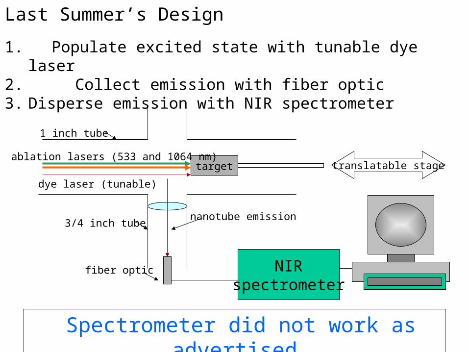
Last Summer’s Design
1. Populate excited state with tunable dye laser2. Collect emission with fiber optic3. Disperse emission with NIR spectrometer
fiber optic
targetablation lasers (533 and 1064 nm)
1 inch tube
3/4 inch tube
translatable stage
dye laser (tunable)
NIRspectrometer
nanotube emission
Spectrometer did not work as advertised

Spectrom
eter
ICCD
lens
aperature
window Fiber optic
Graphite target
White Light Source
Ablation lasers
Green
Red
Translatable support rod
This Summer’s Design1. White light introduced2. Collect transmitted light with fiber optic3. Disperse transmitted light with a spectrometer onto an ICCD to
determine absorbed wavelengths.
Stainless steel
Success: in principle


Optical Setup for Absorption Experiment using X-tube

Absorption Results
0 500 1000 1500 2000 2500 3000 3500
7-20-04 Relative Transmission at 2 cm from Target vs Time
delay (microseconds)
See broad band absorption that covers a long period of time
600 650 700 750 800
Nanotube absorbance experiments 7-20-042 cm from target
32 lasers off lamp on33 2 cm 100 micros34 2 cm 200 micros35 2 cm 400 micros36 2 cm 600 micros37 2 cm 800 micros38 2 cm 1000 micros39 2 cm 1500 micros40 2 cm 2000 micros41 2 cm 2500 micros42 2 cm 3000 micros43 lasers off lamp on
wavelength (nm)

100000
120000
140000
160000
180000
200000
220000
240000
260000
600 650 700 750 800
Nanotube absorbance experiments 7-22-042 cm from target
15 laser off
16 -20
17 -10
18 0
19 10
20 20
21 30
wavelength (nm)
-50 0 50 100 150 200
160000
180000
200000
220000
240000
260000
delay (microseconds)
100% Transmission
0 5000 10000 15000delay (microseconds)
100% Transmission
Absorption seems to reach a
steady state, after a few
hundred microseconds

Is this difference real, reproducible? Don’t know.
0
200000
400000
600000
800000
1000000
600 650 700 750 800
Nanotube absorbance experiments 7-22-04 and 7-23-04Normal and Blank Targets5 mm from target surface
normal target
blank
Difference
wavelength (nm)

Summer Conclusions
• The y and x tubes significantly improve the diagnostic environment, but
– Challenges to reproducibility remain due to1. Pitting of target2. Obstruction of optical components by deposits
• Collected data from surface temperature measurements.
• Collected data from absorption measurements.• Data need additional analysis• I had a great time

Summer Follow-ups
• More analysis of surface temperature data.– obtain temperatures from curve fits.
– relate results to existing models.
• More analysis of absorption data.– Compare differences with blank
– Correct for response and look for spectral features
• Propose improvements to current absorption approach to avoid pitting and depositions.
What other actors should we look for in situ?• metal clusters.• bucky balls (may be spectroscopic methods).• open vs closed tubes.• tubes detected based on length.
Spectroscopy applications• nanotube characterization (chirality, diameter).• quantitative dispersion measurements.• nanotube selective chemistry.• sorting (destroying) of tubes based on chirality and diameter.
Longer Term Follow-Ons


Acknowledgements
William Holmes Sivaram ArepalliPasha Nikolaev
Carl ScottLeonard Yowell
NASA-ASEE Faculty Fellow Program (NFFP)