Embed Size (px)
Citation preview

RTO-MP-071AC/323(NMSG-010)TP/1
NORTH ATLANTIC TREATY ORGANIZATION
RESEARCH AND TECHNOLOGY ORGANIZATION
BP 25, 7 RUE ANCELLE, F-92201 NEUILLY-SUR-SEINE CEDEX, FRANCE
RTO MEETING PROCEEDINGS 71
The Second NATO Modelling andSimulation Conference(Deuxieme conference OTAN sur la modelisation et lasimulation)
Papers presented at the NATO Modelling and Simulation Group (NMSG) Conference held inShrivenham, UK, 24-26 October 2000.
Published July 2001
Distribution and Availability on Back Cover
RT
O-M
P-0
71

���������������� ���� �� ��� ���
������������� ���� ����

RTO-MP-071AC/323(NMSG-010)TP/1
NORTH ATLANTIC TREATY ORGANIZATION
RESEARCH AND TECHNOLOGY ORGANIZATION
BP 25, 7 RUE ANCELLE, F-92201 NEUILLY-SUR-SEINE CEDEX, FRANCE
RTO MEETING PROCEEDINGS 71
The Second NATO Modelling and SimulationConference(Deuxieme conference OTAN sur la modelisation et la simulation)
Papers presented at the NATO Modelling and Simulation Group (NMSG) Conference held inShrivenham, UK, 24-26 October 2000.

The Research and TechnologyOrganization (RTO) of NATO
RTO is the single focus in NATO for Defence Research and Technology activities. Its mission is to conduct and promotecooperative research and information exchange. The objective is to support the development and effective use of nationaldefence research and technology and to meet the military needs of the Alliance, to maintain a technological lead, and toprovide advice to NATO and national decision makers. The RTO performs its mission with the support of an extensivenetwork of national experts. It also ensures effective coordination with other NATO bodies involved in R&T activities.
RTO reports both to the Military Committee of NATO and to the Conference of National Armament Directors. It comprises aResearch and Technology Board (RTB) as the highest level of national representation and the Research and TechnologyAgency (RTA), a dedicated staff with its headquarters in Neuilly, near Paris, France. In order to facilitate contacts with themilitary users and other NATO activities, a small part of the RTA staff is located in NATO Headquarters in Brussels. TheBrussels staff also coordinates RTO’s cooperation with nations in Middle and Eastern Europe, to which RTO attachesparticular importance especially as working together in the field of research is one of the more promising areas of initialcooperation.
The total spectrum of R&T activities is covered by the following 7 bodies:
• AVT Applied Vehicle Technology Panel
• HFM Human Factors and Medicine Panel
• IST Information Systems Technology Panel
• NMSG NATO Modelling and Simulation Group
• SAS Studies, Analysis and Simulation Panel
• SCI Systems Concepts and Integration Panel
• SET Sensors and Electronics Technology Panel
These bodies are made up of national representatives as well as generally recognised ‘world class’ scientists. They alsoprovide a communication link to military users and other NATO bodies. RTO’s scientific and technological work is carriedout by Technical Teams, created for specific activities and with a specific duration. Such Technical Teams can organiseworkshops, symposia, field trials, lecture series and training courses. An important function of these Technical Teams is toensure the continuity of the expert networks.
RTO builds upon earlier cooperation in defence research and technology as set-up under the Advisory Group for AerospaceResearch and Development (AGARD) and the Defence Research Group (DRG). AGARD and the DRG share common rootsin that they were both established at the initiative of Dr Theodore von K´arman, a leading aerospace scientist, who early onrecognised the importance of scientific support for the Allied Armed Forces. RTO is capitalising on these common roots inorder to provide the Alliance and the NATO nations with a strong scientific and technological basis that will guarantee asolid base for the future.
The content of this publication has been reproduceddirectly from material supplied by RTO or the authors.
Published July 2001
Copyright RTO/NATO 2001All Rights Reserved
ISBN 92-837-1069-X
Printed by St. Joseph Ottawa/Hull(A St. Joseph Corporation Company)
45 Sacre-Cœur Blvd., Hull (Quebec), Canada J8X 1C6
ii

The Second NATO Modelling andSimulation Conference(RTO MP-071 / NMSG-010)
Executive Summary
The creation of the new NATO organisation for Modelling and Simulation was approved by the NAC,in 1998. This organisation was set up within the R&T organisation and consists of a NATO Modellingand Simulation Group (NMSG) reporting to the RTB, supported by a permanent office installed inRTA (Neuilly, France): the Modelling and Simulation Coordination Office (MSCO). The NMSGactivity is undertaken according to an “Action plan” approved by the RTB and revised annually. Thisaction plan requires the organisation of an annual M&S conference, in order to leverage the generalknowledge of NATO and PfP nations members and to facilitate cultural and technical exchanges onthis relatively new M&S topic for NATO.
The second RTA NATO Modelling and Simulation Conference was hosted by the UK MOD, inconjunction with the 3rd International Synthetic Environment Conference (ISEC), and was held at theRoyal Military College of Science at Shrivenham 24 to 26 October 2000.
The Conference presented a series of papers during plenary sessions designed to provide an overviewof NATO M&S current best practices, standards, interoperability and reuse. The Conference alsoprovided information on NATO M&S policy, and new M&S activities within the Alliance. In additionthe Conference also addressed themes of research, development and the application of SyntheticEnvironments.
The main objectives selected for the Conference were the following:
1. Provide a forum to present and discuss NATO M&S best practice and policy,
2. Provide an overview of current and future NATO M&S activities pertaining to both thedevelopment and employment of M&S, to include impact assessments and lessons-learned,
3. Present briefings on the latest M&S-related technology developments, relating to NATO Researchand Technology Organisation (RTO) activities and those emerging elsewhere,
4. Discuss updates on M&S-related standards activities (including both NATO Standards Agreementsand commercial standards),
5. Provide a forum to present research, development and the application of Synthetic Environments.
The conference was organised in 6 sessions: 25 papers or presentations were provided. Many enrichingquestions and discussions were raised and the audience expressed its satisfaction with the high standardof papers and presentations. The proceedings contains a technical evaluation of the conference, copiesof published papers and, exceptionally when papers were not available, a copy of the presentation.
Key outcomes and conclusions from the Conference were:
a. The importance of M&S within NATO remains high. SACLANT reaffirmed that M&S willprovide strong support in the key areas of defence planning, training & exercises, support inmilitary operations and in CDE (Concept Development and Experimentation).
b. It was generally accepted that Synthetic Environments and M&S will be successfully applied toequipment capability and operational support & training, but their application to real-time decisionmaking (defence policy, programmes and balance of investments) will be a more difficult andlonger-term problem.
iii

c. The first NATO Federation of simulations (the Distributed Multi-National Defence Simulations -DiMuNDS 2000 Project) was successfully demonstrated at the Conference. This impressedattendees by the demonstrative impact of the federation of simulations and the prospect it providedfor future Computer Assisted Exercising (CAX) capabilities to support, in particular, the NATOCJTF.
d. The Synthetic Environment Data Representation and Interchange Standard (SEDRIS ) thatprovides the means to represent environmental data (terrain, ocean, air and space), and promote theunambiguous, loss-less and non-proprietary interchange of environmental data is becoming morewidely used within the M&S community and is now likely to be recommended as a NATOSTANAG.
e. The integration of human behaviour at different levels within simulations will remain a verydifficult problem and challenge for the M&S community.
f. Major General A C Figgures, Capability Manager (Manœuvre) UK MOD, provided the Conferencewith a fitting end message encouraging the SE and M&S community “to continue their efforts,without forgetting the primary objectives of providing military personnel with effective, affordableSEs which are also credible to military and scrutiny staffs. SEs must be led by Customer pull andnot by Technology push”.
iv

Deuxieme conference OTAN sur la modelisationet la simulation
(RTO MP-071 / NMSG-010)
Synthese
La creation d’un nouvel organisme OTAN de mod´elisation et simulation (M&S) a ´ete approuv´ee par leNAC en 1998. Cet organisme a ´ete cree au sein de l’Organisation pour la recherche et la technologiede l’OTAN (RTO) et consiste en un Groupe OTAN de mod´elisation et simulation (NMSG) qui rendcompte au RTB et qui dispose d’un bureau permanent dans les locaux de la RTA `a Neuilly (France) : lebureau de coordination des activit´es OTAN de mod´elisation et simulation (MSCO). Les activit´es duNMSG sont entreprises dans le cadre d’un “Plan d’action” approuv´e par le RTB et revu tous les ans. Ceplan d’action pr´evoit l’organisation d’une conf´erence M&S annuelle, qui a pour objectif de sensibiliserles pays membres de l’OTAN ainsi que les pays du PpP `a ce sujet relativement nouveau pour l’OTAN,ainsi que de faciliter les ´echanges culturels et techniques dans ce domaine.
La deuxieme conf´erence RTA/OTAN sur la mod´elisation et la simulation a ´ete organis´ee par leMinistere de la D´efense du Royaume-Uni, conjointement avec la 3`eme Conf´erence Internationale surles Environnements Synth´etiques (ISEC) au Royal Military College of Science de Shrivenham du 24au 26 octobre 2000.
Lors des s´eances pl´enieres, la conf´erence donna lieu `a une s´erie de communications offrant un aper¸cudes meilleures pratiques actuelles, des normes, de l’interop´erabilite et de la r´eutilisation de la M&Sdans l’OTAN. Elle a ´egalement apport´e des informations sur la politique de l’OTAN en mati`ere deM&S, ainsi que des nouvelles activit´es de mod´elisation et simulation au sein de l’Alliance. En outre,les themes de la recherche, du d´eveloppement et de l’utilisation des environnements synth´etiques ontete abord´es.
Les principaux objectifs de la conf´erence ´etaient les suivants :
1. Offrir un forum pour la pr´esentation et la discussion des meilleures pratiques et de la politique del’OTAN en matiere de M&S.
2. Donner un aper¸cu des activit´es M&S actuelles et futures de l’OTAN concernant le d´eveloppementet la mise en œuvre de la M&S, y compris l’´evaluation de sa port´ee et les enseignements d´eja tires.
3. Presenter des briefings sur les derniers d´eveloppements dans le domaine des technologies demodelisation-simulation en relation avec les activit´es de l’Organisation pour la recherche ettechnologie de l’OTAN (RTO), ainsi qu’avec toutes autres activit´es emergentes.
4. Discuter des mises `a jour des normes dans le domaine de la M&S (comprenant `a la fois toutes lesSTANAGs et les normes commerciales).
5. Presenter un forum pour la recherche, le d´eveloppement et la mise en œuvre des environnementssynthetiques.
Le symposium a ´ete organis´e en six sessions : 25 diff´erentes communications ont ´ete presentees. Bonnombre de questions int´eressantes ont ´ete soulev´ees et des discussions fructueuses ont eu lieu. Lesparticipants ont exprim´e leur satisfaction devant le haut niveau des communications et despresentations. Le compte rendu de la conf´erence contient une ´evaluation technique de la conf´erence,des copies de communications ayant ´ete publiees et, exceptionnellement, en cas de non-disponibilit´edes communications, des photocopies des pr´esentations.
v

Les resultats et conclusions principales de la conf´erence furent :
a. La M&S presente toujours un grand int´eret pour l’OTAN. Le SACLANT a r´eaffirme l’importancedu soutien qui sera fourni par la M&S dans les domaines cl´es que sont la planification de ladefense, l’entraˆınement et les exercices, le soutien des op´erations militaires et l’activit´e CDE(developpement de concept et exp´erimentation).
b. Il a ete generalement admis que les environnements synth´etiques (SE) et la M&S pourront ˆetreappliques avec succ`es au soutien des op´erations et `a l’entraınement, ainsi qu’`a l’amelioration descapacites des ´equipements, mais que leur mise en œuvre pour la prise de d´ecisions en temps r´eel(politique de d´efense, programmes, ´equilibre des investissements) s’av´erera plus difficile et pluslongue a realiser.
c. La premiere federation de simulateurs de l’OTAN (le projet de simulations r´eparties de d´efensemultinationale - DiMuNDS 2000) a ´ete presentee avec succ`es lors de la conf´erence. Lesparticipants ont ´ete impressionn´es par l’impact de cette “f´ederation”, ainsi que par la perspectivequ’elle fournit pour les exercices assist´es par ordinateur (CAX) en particulier pour le soutien desoperations GFIM de l’OTAN.
d. La norme relative aux donn´ees pour la repr´esentation et les ´echanges de donn´ees surl’environnement synth´etique (SEDRIS ) qui permet de repr´esenter des donn´eesenvironnementales (terrestres, maritimes, a´eriennes et spatiales) et de promouvoir des ´echangessans pertes et exclusives de donn´ees environnementales, est de plus en plus utilis´ee par lacommunaut´e M&S et pourrait devenir un STANAG OTAN.
e. L’integration du comportement humain `a des niveaux diff´erents dans les simulations demeurera unprobleme tres difficile et un d´efi pour la communaut´e de la M&S.
f. Le Major General A C Figgures, responsable Capacit´es (Manœuvres) au minist`ere de la D´efensebritannique, a prononc´e un discours de conclusion tr`es adapt´e dans lequel il a encourag´e lescommunaut´es SE et M&S `a “poursuivre leurs efforts, sans oublier les objectifs prioritaires qui sontde fournir aux militaires des environnements synth´etiques efficaces et abordables qui soientacceptables `a la fois pour les militaires et les v´erificateurs. Les SE doivent progresser sousl’impulsion de la demande de la client`ele et non sous l’effet de la pouss´ee technologique”.
vi

Contents
Page
Executive Summary iii
Synthese v
Foreword ix
Group Officers x
Reference
Technical Evaluation Report Tby J.L. Igarza
TUTORIALS
An Update of HLA Standards Efforts TU1by B. Waite
Introduction to SEDRIS TU2by P. Foley and C. Matthews
OPENING SESSION
Welcoming Address - ‘Synthetic Environments - Managing the Breakout’ WAby M. Markin
Opening Address for NATO M&S Conference OAby G. Sursal
Keynote Address KNby G.J. Burrows
Industry’s Role IR†by M. Mansell
The RMCS SSEL Iby J.R. Searle
SESSION 1: POLICY, STRATEGY & MANAGEMENT
A Strategy for the Provision of Infrastructure and Services in Support of Synthetic 1Environments
by J.M. Henderson and R.J. Salmon
CANADA M&S ORGANISATIONS:
An Integrated Canadian Approach to Concept Development, 2Joint Experimentation and Modelling and Simulation
by J. Bovenkamp
The Establishment of the Army Simulation Centre 3by J.L. Cyr
An R&D Strategy for the Way Ahead in M&S for the Canadian Air Force 4by J.P. Landolt and J.R. Evans
Italian M&S Center Project 5by A. Surian
† Paper not available at time of production.
vii

SEMB Presentation 6by M. Mansell
Introduction to the DiMuNDS 2000 Project and Demonstration 7by D. Coppieters and J. Hamers
SESSION 2: BUILDING SYNTHETIC ENVIRONMENTS, INTEGRATION ANDSTANDARDS ISSUES
Emerging ISO Standards for the Representation of Physical Environmental Data 8by J. Cogman
Promoting Re-use in Synthetic Environments by Developing Generic Components 9by R. Smith
The Use of DIS and HLA for Real-Time Virtual Simulation – A Discussion 10by J. Steel
SESSION 3: BUILDING SYNTHETIC ENVIRONMENTS, REPRESENTATION ISSUES
NATO Long Term Scientific Study (LTSS/51) on Human Behaviour Representation 11by U.K.J. Dompke
Synthetic Environments – The Met. Office Approach 12by B.W. Golding
Dynamic Terrain in the Synthetic Environment 13by R. Simons
SESSION 4: SYNTHETIC ENVIRONMENT APPLICATIONS,EXERCISES AND TRAINING
Synthetic Environments in Advanced Distributed Learning 14by M. Kelly and J. Allen
The Use of Virtual Simulation for Dismounted Infantry Training 15by J.D. Smith and J. Steel
Paper 16 withdrawn
Aircrew Mission Training Via Distributed Simulation – A NATO Study 17by B.N. Tomlinson
Computer Generated Forces Based on Tactical Application of Principles of Combat 18Survivability
by S.N. Price, D.K. McBride and V. Sastry
Exercise - ‘Reaction Combinee’ 19by M. Watson and J.-L. Igarza
SESSION 5: SYNTHETIC ENVIRONMENT APPLICATIONS,EQUIPMENT ACQUISITION
Paper 20 withdrawn
Paper 21 withdrawn
Simulation Based Acquisition in the Joint Strike Fighter Program 22†by R.J. Hartnett and J.A. “Chips” Lawler
A Simulation Framework for Command and Staff Training 23by C. (Randy) Ball
UK Future Offensive Air System (FOAS): From Requirements to Operation 24by P. Baker, K. Martin, I. Page and N. Smith
Conference Closing Remarks CRby A. Figgures
† Paper not available at time of production.
viii

Foreword
Following the success of the first NATO RTA Modelling and Simulation Conference held in Norfolk, USA in October1999, a second Modelling and Simulation Conference was held in the UK over the period 24 to 26 October 2000. Itwas hosted by the UK Ministry of Defence and the Royal Military College of Science at Shrivenham in the UK andwas held in conjunction with the International Synthetic Environment Conference. The Conference had the themes ofmodelling and simulation interoperability, the NATO M&S Master/Action Plan, simulation policy, new M&Sactivities within the Alliance and Synthetic Environments.
ix

Group OfficersNMSG Chairman: NMSG Vice-Chairman:Dir BWB E. SCHWAN Ms L. E. McGLYNNBWB FE 1 Special Asst to DUSA (OR) for M&SPostfach 7360 and Light Forces StudiesKonrad-Adenauer-Ufer 2-6 Room 1E643, PentagonD-56057 Koblenz Washington, DC 20310Germany U.S.A.
PROGRAMME COMMITTEE
Chairman
Col. R. G. LeeDirector International Symposia
Cranfield UniversityThe Royal Military College of Science
Shrivenham, Swindon, Wiltshire SN6 8LAUnited Kingdom
e-mail: [email protected]: +44 1793 785648Fax: +44 1793 785325
Vice-Chairman
Mr. G. J. BurrowsHead, Modelling and Simulation Coordination Office
Research and Technology AgencyBP 25
7 rue Ancelle92201 Neuilly-sur-Seine Cedex
Francee-mail: [email protected]
Tel: +33 1 55 61 22 90Fax: +33 1 55 61 22 99
Members
Dr J. M. Aitchison Cdr.G. Ameyugo CatalanDirector Simulation & Synthetic Environment Lab. Modelling and Simulation Coordination OfficeCranfield University Research and Technology AgencyThe Royal Military College of Science BP 25Shrivenham, Swindon, Wiltshire SN6 8LA 7 rue AncelleUnited Kingdom 92201 Neuilly-sur-Seine Cedexe-mail: [email protected] FranceTel: +44 1793 785276 e-mail: [email protected]: +44 1793 784196 Tel: +33 1 55 61 22 92
Fax: +33 1 55 61 22 99
Mr D Bowman LtCol G. W. HendersonBritish Aerospace MA&A DS (Sim/OA) EGW DivisionWarton Aerodrome (W293H) The Royal Military College of ScienceWarton, Nr Preston, Lancs PR4 1AX Shrivenham, Swindon, Wiltshire SN6 8LAUnited Kingdom United Kingdome-mail: [email protected] e-mail: [email protected]: +44 1772 855462 Tel: +44 1793 785 566Fax: +44 1772 856498 Fax: +44 1793 785 663
x

Mr M. J. T. Hewetson Mr A. ParfittManager International Symposia SECOCranfield University Ministry of DefenceThe Royal Military College of Science c/o Room 1189, Main BuildingShrivenham, Swindon, Wiltshire SN6 8LA WhitehallUnited Kingdom London SW1A 2HBe-mail: [email protected] United KingdomTel: +44 1793 785 847 e-mail: [email protected]: +44 1793 784865 Tel: +44 171 218 6115
Fax: +44 171 218 6481
NATO Modelling and Simulation Co-Ordination Office(RTA/NMSCO)
Mr. G. J. Burrows (Head)Cdr.G. Ameyugo Catalan (Deputy, Head)
Mr Jean-Louis Igarza (Chief Scientist)Research and Technology Agency
BP 257 rue Ancelle
92201 Neuilly-sur-Seine CedexFrance
xi

���������������� ���� �� ��� ���
������������� ���� ����

T-1
Technical Evaluation Report
byDr. Jean-Louis Igarza
NATO/ RTAMSCO Chief ScientistBP 25, 7 rue Ancelle
F-92201 Neuilly sur Seine CedexFrance
At the turn of the century, NATO’s roles are expanding (despite shrinking defence budgets) andModelling and Simulation (M&S) is recognised as a key issue by the Alliance. Since the earlynineties, the continuous evolution of the technology has demonstrated that M&S should be anunavoidable basis for the exercising and training activity, the setting of plans, the assessment ofnew doctrines and tactics, etc. The importance of M&S for NATO has been demonstrated by someinitiatives, starting around 1995, when ad-hoc working groups, conferences, workshops anddemonstrations have been organised by Alliance organisations at all levels. From those initiatives,many useful reports have been produced showing a growing interest for this subject.
But, the most significant event occurred when, by the end of 1998, the NAC with the support ofboth the CNAD and the MC, took the option to set up a new and dedicated organisation within theResearch and Technology Organisation (RTO), recognising de facto the underlying technicalcharacter of this activity. This new M&S organisation started its activity within the RTO in themiddle of 1999. However, the 2000 NATO M&S conference is already the second M&Sconference that has been organised.
The 2000 NATO Modelling and Simulation conference was hosted by the UK, in conjunction withthe 3rd International Synthetic Environment conference and was held at The Royal MilitaryCollege of Science in Schrivenham (England).
More than twice the number of papers as slots were available were received by the conferenceProgramme Committee and selection of presentations appeared difficult. However, a high qualityselection of papers covering a good cross-section of M&S activities were eventually selected by theProgramme Committee which were appreciated by some 180 people who attended the conference.
The conference was organised in different sessions by a grouping of papers in well identifiedthemes in order to facilitate and generate discussions on common concerns.
Introduction
The UK introduced the Synthetic Environment (SE) concept in the early 90s. SE has a number ofdifferent definitions around the world. The UK has an official definition: “A synthetic environment(SE) links a consistent set of models, simulations, people and real equipment into a commonrepresentation of the world to provide consistency and concurrency across previously discreteactivities, thereby achieving timeliness, cost-effectiveness and risk reduction”. Therefore, theview in the UK is very general, similar to that of the US “Advanced Distributed Simulation”concept. The UK Synthetic Environment concept encompasses the M&S domain, since it integrateshuman organisations and real military systems to provide virtual worlds for different purposes. Thisconcept has been presented at many previous conferences.
This evaluation paper is not a rigorous technical evaluation. In his closing remarks to theconference, Major General Figgures said that “SE should be led by customer push, not bytechnology pull”. The conference was the illustration of that very perceptive sentence, since not all
T-2
technology pull�. The conference was the illustration of that very perceptive sentence, since not allpapers had a technical content. The papers covered: description of organisations dedicated to M&Sor SE, new projects, feedback from successful demonstrations, future researches, etc. Even iftechniques or technologies were not always present in the presentations or papers, attendees showeda large interest in the information they conveyed and generally made highly favourable commentsconcerning the content of papers and conference organisation.
Key outcomes and conclusions from the Conference were:
a. The importance of M&S within NATO remains high. SACLANT reaffirmed that M&S willprovide strong support in the key areas of defence planning, training & exercises, support inmilitary operations and in CDE (Concept Development and Experimentation).
b. It was generally accepted that Synthetic Environments and M&S will be successfully applied toequipment capability and operational support & training, but their application to real-timedecision making (defence policy, programmes and balance of investments) will be a moredifficult and longer-term problem.
c. The first NATO Federation of simulations (the Distributed Multi-National Defence Simulations- DiMuNDS 2000 Project) was successfully demonstrated at the Conference. This impressedattendees by the demonstrative impact of the federation of simulations and the prospect itprovided for future Computer Assisted Exercising (CAX) capabilities to support, in particular,the NATO CJTF.
d. The Synthetic Environment Data Representation and Interchange Standard (SEDRIS�) thatprovides the means to represent environmental data (terrain, ocean, air and space), and promotethe unambiguous, loss-less and non-proprietary interchange of environmental data is becomingmore widely used within the M&S community and is now likely to be recommended as a NATOSTANAG.
e. The integration of human behaviour at different levels within simulations will remain a verydifficult problem and challenge for the M&S community.
f. Major General A C Figgures, Capability Manager (Manoeuvre) UK MOD, provided theConference with a fitting end message encouraging the SE and M&S community �to continuetheir efforts, without forgetting the primary objectives of providing military personnel witheffective, affordable SEs which are also credible to military and scrutiny staffs. SEs must be ledby Customer pull and not by Technology push�.

T-3
Opening session:
Welcoming Address,by Mr M S Markin, Director General (Research & Technology) UK MOD
The speaker took the option to recall first that the UK definition for SE is larger than the somewhatrestrictive view of representing the natural and human made environment. Strong messages werepromoted from the R&T senior representative. For UK MoD, the main goal of SE is “To enhancethe quality and efficiency of military output by establishing Synthetic Environments as an integraland proven part of the Defence Process within the United Kingdom and Internationally”. A clearand concise statement indeed. A rapid assessment of the current uses of SE in the UK has beenaccomplished which emphasises that the uses should be more various in the near future. A longterm evolution of the potential successful application of SEs was presented distinguishing betweenthe three major application domains, namely: equipment capability, operational support & training,real time decision making (defence policy, programmes and balance of investment). Both, the firstand second domains would apparently have a promising forecast evolution, the third one should beslightly more difficult to tackle. Future management challenges were identified as economy, datareduction & analysis, synergy with operational analysis, organisational culture, commercial aspectsand sustainability. Less numerous were the highlighted technical challenges (time management andmultiple representation), but they were not to be underestimated. In conclusion, a very clear andattractive presentation, demonstrating the support of UK senior management to the SE activity.
Opening Address,by Dr. Gokay Sursal, Senior scientist, NATO, SACLANT
Dr. Sursal gave the SACLANT presentation on behalf R Adm D M Crocker who was not available.This presentation confirmed the strong commitment of SACLANT to the M&S activity. SACLANTreaffirmed that M&S will provide strong support in four main activity areas: defence planning,training and exercises; support of military operations and in CDE (Concept Development andExperimentation).
This was a very good and clear presentation which provided firm encouragement to people involvedin the NATO M&S activity in pursuing their ambitious programme of work.
Keynote Address, NATO,by Mr Graham Burrows, Head of Modelling and Simulation Coordination Office (MSCO), NATOResearch & Technology Agency,
Graham presented an overview of the NATO R&T Organisation that was not well known in the SEcommunity, which is generally more interested in development than in research activities. NewNATO R&T challenges have been introduced and the M&S action plan was described in somedetail with respect to M&S objectives as attributed to the new M&S organisation. The newlyestablished procedure for conducting NATO Modelling & Simulation Group (NMSG) activitieswas presented. The speaker underlined the importance of that process, in particular, in establishinga “3-Years Rolling Implementation Plan” of activities facilitating the forecast of allocation ofresources to fund demonstration and implementation phases of projects.

T-4
Industry’s Role,by Mr M Mansell, Chairman, UK Synthetic Environments Management Board
This was a short introduction (regretfully too short) from the industry leader, which wascomplemented by a more detailed and attractive presentation on behalf the UK SyntheticEnvironments Management Board given during the following session. Mr Mansell has chaired theSEMB for 4 years and was highly qualified to welcome attendees on behalf of the UK industrycommunity.
Introduction to the RMCS Simulation and Synthetic Environment Laboratory (SSEL),by Mr J R Searle, Manager, Simulation and Synthetic Environment Laboratory
This last presentation of the first session was the first of several presentations provided by membersof the Royal Military College of Science, host of the conference. Born in 1995, SSEL is a youngand attractive organisation. It was established primarily for education & research purposes, but hasrapidly grown now covering a large scope. It welcomes not only young students, but alsoexperienced military personnel providing them with a sound background for employment related tofuture M&S/ SE activities. On the invitation of the speaker, the SSEL was subsequently visited by alarge number of attendees. Those visits, in conjunction with the industry demonstrations availablein the exhibit part of the conference, provided a firm foundation and a practical view to theattendees, which complemented and enriched the somewhat abstract presentations of the followingsessions of the conference.

T-5
Session 1: POLICY, STRATEGY & MANAGEMENT
Establishment of a more extensive and rational use of SE has forced national or internationalorganisations to examine carefully the way for managing that activity. If new organisations are notcreated and adequate services are not established, the full potential of SEs cannot be achieved.Some nations have re-organised their structures to implement SEs, whilst other nations have co-ordinated the activities of SEs in their existing organisations. Many presentations of this sessionillustrated different ways taken by nations, trying to achieve the SE full potential. The firstafternoon of the conference ended with a presentation on a very different topic: the introduction ofthe DiMuNDS1 2000 experimentation. This introduction was purposely placed in this position, inorder to increase the number of opportunities of people to attend a demonstration of DiMuNDS, inthe exhibit part of the conference. This very successful demonstration was presented as an excellentexample of the capability and availability of the technology to help solve training issues within theAlliance.
• A Strategy for the Provision of Infrastructure & Services in Support of SyntheticEnvironments,by Mrs J Henderson, SECO, DG(R&T), MOD, UK
SE technology has been recognised by the UK for sometime as having a high potential for allactivities of military business. Impressive demonstrations have been set up and dedicated SEorganisations have been established in co-operation with the UK industry and within the MoD. But,there are some organisations within the MoD that consider current SEs have not yet demonstratedtheir full potential. A lack of common infrastructure and common services has been identified andthis is the process that is now being corrected. Jenni Henderson clearly explained the efforts, newservices and organisations that are being set up to achieve the goal of providing an adequatebackground for the SE community in the UK. Current and future UK efforts are consistent with theobjectives proposed in the NATO M&S action plan. The Technical Evaluator warmly recommendsthat this paper and the attached presentation should be reviewed with the prospect of current andfuture co-operations with the UK.
Canada M&S organisations :
Three different presentations were provided by Canada. First, John Bovenkamp introduced theCanadian efforts at the joint level. He was followed by Lt.Col. Louis Cyr, for the Army, and by Dr.Landolt, for the Air Force. These 3 presentations showed the importance that Canada is nowattaching to SEs.
• An Integrated Canadian Approach to Concept Development (CDE), JointExperimentation (JE) and M&S,by Dr John Bovenkamp, Strategic Planner, DST Pol/ DRDC, Canada
Canada only started to reorganise for the “creation of its future forces of 2020”, in November 1998.But, there has been a rapid evolution since that date. Organisation of symposia, publication ofimportant documents such as “Strategy 2020” or “Strategic Capability plan” have opened the doorto modernisation and reorganisation. The most important document is the “concept paper on a tri-tier integrated approach to CDE/ JE/ M&S”. This three tier concept is linked to the threehierarchical levels: strategic, operational and tactical. More specifically, Tier 1 is relative to ACD(advanced concept developments), the second will deal with JE (joint experimentation) and Tier 3will be concerned by the establishment of an environmental CDE (ECDE) activity. A project to 1 Distributed Multi-National Defense System

T-6
create the Joint Experimentation Centre (JEC) was discussed which was considered to be consistentwith allied initiatives and, in particular, NATO projects. This was a very important and informativepresentation.
• The Establishment of the Canadian Army Simulation Centre ,by Lt Col Louis Cyr, CD, Director, Army Simulation Centre, LFDTS, Canada
The Canadian Army Simulation Centre was established in 1996, in response to the Army overall re-organisation. The presentation described in some detail this new army organisation and its missions.The Synthetic Environment Canadian concept seemed to be very close to the corresponding UKconcept. The Army centre is responsible for the support to operations, combat development andtraining at tactical level, but the development and acquisition of Army armaments are not part of itsoverall mission. As in many allied nations, Canadian Army training at tactical level is based on anextensive use of the JANUS simulation, facilitating co-operation with other nations. Thispresentation was a clear and informative picture of the Canadian Army SE activity and projects.
• An R & D Strategy for the Way Ahead in M&S for the Canadian Air Force,by Dr J P Landolt, Defence & Civil Institute of Environmental Medicine, Canada
This presentation was different from both previous Canadian presentations, since it summarised theresults of a long term study on “what new technologies and methodologies could offer to the AirForce”. The study provided a good overview of current and planned characteristics of M&S, a listof concerns which are important and equally shared by other nations and organisations. The secondpart of the presentation was more focused on Air Force issues. The presentation emphasised therequirements for secure networking capabilities. This is an important issue concerning the nationsand the Alliance as the number of developments of distributed SEs increase.
• Italian M&S Center Project,by Col A Surian, Chief, J5 Simulation Division, Italian Joint Operations HQ
Italy perhaps is late in developing a training capability (at theatre level), when compared with someother nations, however this capability will soon be filled with; the creation of the CIMSO (theItalian “Joint Operational Modelling and Simulation Centre”) and the adopted approach whichpragmatically relies on the acquisition of a common tool-set already selected by many alliedpartners. Colonel Surian’s presentation provided a clear and attractive overview, showing theprogress accomplished so far, without avoiding potential difficulties to come.
• SEMB Presentationby Mr M Mansell, Chairman, UK Synthetic Environments Management Board
Mr Mansell completed very well his short introduction of the opening session (on behalf of UKindustry), by a very attractive and largely informative presentation given on behalf of the SyntheticEnvironments Management Board (the UK SE steering committee and acting advisory council). Hehas been chairman of the SEMB for 4 years which is a key organisation responsible for advising SEtechnical policy. Using multimedia devices, he succeeded in giving a large and excellent overviewof current activities and capabilities. After recalling past and current major projects supported bySEMB (such as FlasHLAmp, ADSE or FOAS), the applicability of SEs were reviewed according tothe SEMB vision. Nine different application areas or layers in the SE activity are considered:geopolitical analysis, strategic studies, costs/logistics, war-gaming/battle modelling, warfare to-morrow, product definition, component design, costs and manufacture, product support. Theimportance of considering costs and cost-effectiveness in SE was emphasised and indications weregiven on fields in which industry could be involved and more generally how it could help. The

T-7
presentation was successful and attractive. Partnership between industry and government withinUK SEMB could provide a good example to other allied nations if co-operation between industryand government is not so successful or not so well organised.
SEMB is a national organisation promoting the UK national SE activity. However, in response to aquestion, Mr Mansell stated that the SEMB is not closed to international co-operation.
• Introduction to the DiMuNDS 2000 project and demonstration,by Dirk Coppieters, NATO C3 Agency and Joost Hammers, NL, TNO Defence Research
DiMuNDS2 2000 is a demonstration project supporting the preparation of the leadingPATHFINDER NATO program. The importance, aim and objective of the project was clearlyunderlined by a short, but very convincing introduction from Lt Col Gareth Pugh of the UK MoD,given on behalf the NATO Modelling & Simulation Group (NMSG) and its subordinate SimulationAdvisory Task Group (SATG) responsible for the DiMuNDS experiment.
Both presenting speakers (who were co-responsible for leading that successful project) recalled thefirst objective of DiMuNDS: to demonstrate that a CAX capability for training a NATO CJTFcould be developed by interconnecting national operational simulations already existing using theHigh Level Architecture. The selected scenario and the main components of the implementing SEas distributed on a LAN were described. Five nations co-operated : France, Germany, theNetherlands, the UK and the US. Adjacent to the conference theatre, a DiMuNDS 2000demonstration was provided. Many visitors were welcomed, attracted by the excellent introductionof both project leaders. A large majority of the visitors stated that they were impressed by thedemonstrative impact of the federation of simulations and the prospect it provided for future CAXcapabilities.
2 Distributed Multi-National Defense System

T-8
Session 2 : BUILDING SYNTHETIC ENVIRONMENTS, INTEGRATIONAND STANDARDS ISSUES
• Emerging ISO Standards for the Representation of Physical Environmental Databy Dr J C Cogman, Thomson Training & Simulation, UK
This presentation was mainly focused on standardisation issues and appeared to be complimentaryto SEDRIS tutorials organised before and at the end of the conference. A clear distinction wasestablished between what many people now call “SE” and what should be named “Synthetic (orSimulated) Natural Environment”: a unique slide (the third one of the presentation) provided a cleardemonstration of how different requirements could be merged in SEs. Interoperability is the bigissue and defines the requirements for standards. The standardisation process selected by theSEDRIS organisation was described and the related schedule which is important for the M&Scommunity was announced. SEDRIS appears as a very sensible approach. The presentation was ofsignificance to the M&S community. The presentational talents of the speaker made thispresentation one of the best of the conference. Many questions were posed primarily related to thestandardisation process.
• Promoting re-use in Synthetic Environments by developing Generic SE Componentsby Mr R Smith, Matra BAe Dynamics, UK
This presentation was an overview about interoperability issues provided by a company largelyinvolved in the M&S world. It provided an interesting feedback from their own experience. Manyinteresting and very general issues were raised: how to navigate around the continual evolution oftechnology and standards (the DIS versus HLA dilemma), how to impose a common standard to thewhole Matra BAe Dynamics company? MBD found an original solution named SE-API providing aDIS/HLA highway. No other choice was made available, however it allows users to defer theirchoice between DIS and HLA, to reuse existing models without forcing them to be upgraded to anew standard. Some examples of applications were presented. For new components, “genericity” isthe rule and standardisation has shown its importance in that process. This experience is at an earlystage, but there has already been some interest shown in this approach. This process provides analternative to a voluntary process, that of the imposition of a unique standard: only, the future willreveal what is the best policy …
• The Use of DIS and HLA for Real Time Virtual Simulation – A Discussionby Mr J Steel, Cranfield University, RMCS Shrivenham, UK
A controversial subject, but addressed here in an original, apparently neutral and pragmatic way.The study presented by the speaker is really a great step forward even if restricted on the use ofboth standards for real time applications. Many important aspects have been studied in thecomparison of both standards which produced an attractive presentation and a well documentedpaper, easy to read and recommended. This was considered by the Technical Evaluator to beworthy of more detailed attention. Nevertheless, all questions had not been treated in the paper andthe reader is strongly encouraged to pursue his study. One of the best papers of the conference:since it coupled with the two previous ones and, overall, it provided the best session of this annualconference!

T-9
Session 3: BUILDING SYNTHETIC ENVIRONMENTS, REPRESENTATIONISSUES
• NATO Long Term Scientific Study on Human Behaviour RepresentationBy Dr U Dompke, ITIS at the Federal Armed Forces University, Munich, Germany
Uwe reported on the recent work completed by NATO on the very difficult problem of integratinghuman behaviour at different levels within simulations. Forecasting what will be the future of thatactivity for the next 15 years and predicting what important progress could be accomplished is areal challenge. There is not doubt than significant improvements have to be completed before theset of listed technologies can provide the results they promise. This presentation raised more issuesthan solutions to the problems. But, the work completed has the merit of clearly exposing whatproblems are outstanding and to make recommendations for improving the way research isundertaken to solve these important issues.
• Synthetic Environments – The Met Office ApproachBy Dr B Golding, The Meteorological Office, UK
This was one paper issued by a “non defence organisation” which raised issues how the UK METoffice considers the SE business: the audience was not disappointed. The speaker highlighted thetremendous progress that could be achieved by integrating effects of dynamic environment withinmodels and simulations. Apparently, co-operation between the MET office and militaryorganisations has been fruitful since the office understands clearly what are the requirements of“simulationists”.
When simulations need to be very realistic, the paper advises practitioners to re-examine how theyneed to take into account meteorological conditions: weather evolves continuously in real world(the concept of “dynamical” weather as opposed to the “static” view often provided by legacysimulations), the uncertainty of weather forecasts very rarely taken into account, etc.. This was avery good paper and presentation.
• Dynamic Terrain in the Synthetic EnvironmentBy Ms R Simons, US Army STRICOM
Before using the SE term, the author clearly explained what she was referring to: this STRICOMresearch concentrates on the interactions between military systems (mainly land vehicles) and thedynamic natural environment. The effects of man made systems on the natural environment arevery important features of the live military activity. Unfortunately, this is a characteristic rarelytaken into account by current simulations. Past reasons for that were twofold: first, methodological,since no method was made available, second, technical, due to the insufficient capabilities ofgraphical machines for displaying detailed phenomena in real time. The STRICOM study presentedinteresting progress made thanks to the tessellation concept. That work demonstrated the possibilityto increase capacities of future simulation systems in supporting individual and tactical training.This was an interesting paper and a good presentation.

T-10
Session 4: SYNTHETIC ENVIRONMENT APPLICATIONS, EXERCISESAND TRAINING
Synthetic Environments in Advanced Distributed LearningBy Mr M Kelly & Mr J Allen, Defence Evaluation & Research Agency, UK; presented by Mr JAllen
This paper exposed an interesting comparison and discussion into two related domains largelyevolving on parallel tracks: the SE world and the advanced distributed learning (ADL) initiatives.Both communities have developed their own standards and/or have adopted some existingtechnologies. But, few actions have started so far to accommodate the way those two areas areinteracting. By example, it is clear that ADL should exploit the SE technology and that the SEworld could benefit from some Internet technologies and standards which are already largely usedin the ADL activity. Two initiatives were briefly described : the UBT (Unit Based Training)initiated by the British Army and the standardisation effort for ADL named SCORM (ShareableCourseware Object Reference Model). This was an interesting subject, paper and presentation on acurrent concern for the NATO M&S organisation.
The use of Terrain Databases and Virtual Simulation for Dismounted Infantry TrainingBy Mr J Steel & Mr J D Smith, Cranfield University, RMCS Shrivenham, UK
A clear overview was presented of the very specific issues raised by the use of virtual simulation(or, more generally, SEs) for training of dismounted infantrymen. The review showed clearly thegeneral deficiencies or drawbacks of current simulators. The RMCS has started (and alreadycompleted, in some cases) a number of related studies on SE application: highly detailed terraindatabases, flight deck officer (Royal Navy) and CATT infantry modelling are three projects typicalof that activity. This was an informative and easy to follow presentation. The paper isrecommended for people who do not know this particular topic very well.
Tactical Weapon Simulation SystemsBy Dr V Penev, Mr V Stoianov, Mr G Georgiev, Institute of Control & System Research, Bulgaria
This presentation was unfortunately cancelled.
Aircrew Mission Training via Distributed Simulation – a NATO Study
By Mr B N Tomlinson, Defence Evaluation & Research Agency, UK
The Technical Evaluator considered this to be one of the best papers and presentation of theconference. Those who know the author were not surprised. The study demonstrated that the use ofSE is or will soon be a cost-effective way for collective training within NATO, for the benefit ofcombined operations. The technology is largely mature, nations are gaining experiences despite thefact that some aspects still require research and/or improvement. NATO will be interested infollowing that path. That paper, and the associated presentation, were not only interesting from atechnical point of view, but the author proposed a way forward for NATO, identifying technicalissues to tackle, but not forgetting that technology should be assessed with respect to operationalrequirements.

T-11
Computer Generated Forces Based on Tactical Application of Principles of CombatSurvivabilityBy Prof D K McBride, Mr S Price, Dr VVVSS Sastry, Institute for Simulation & Training,University of Central Florida, USA / Cranfield University, RMCS Shrivenham, UK
This was a long and very detailed paper. The authors well identified and recalled the drawbacks ofCGFs as they are available to-day. Despite the fact that the speakers rarely highlighted the terms“validity” or “validation”, the main issue was how to effectively “VV&A” current CGFs. It isgenerally agreed that there is a need to start further studies to improve the human behaviourmodelling in future CGF or more generally the military validity of those tools for training or studypurposes. But, it is not clear that one should start from the simplistic model of Ball. First, thismodel could be mathematically valid if the stochastic independence of related events could beproved and it is already difficult to clearly identify them. Second, even if it was possible to provethe validity of the simple and attractive formula provided, it is not known how to estimate thevalues of the ingredients even in simple cases. This model has been used for sometime, but manypeople have now abandoned it due to reasons highlighted above. It should be also added that theBall model is static in nature and the reality is naturally dynamical.
Nevertheless, the first part of this paper is recommended (the assessment of current CGFscapabilities). It is agreed that further researches should be started, but it is not clear on the proposedbasis, except if it is used as a guideline. This pessimistic assessment is based on previousexperiences which have demonstrated that the use of such models is neither practical, nor valid.
Exercise ‘Réaction Combinée’Mr Mike Watson, DERA, UKM. Jean-Louis Igarza, Centre d’Analyse de Défense & NATO/ RTA/ MSCO, France
This paper provided a feedback from a real distributed and combined experiment heldsimultaneously, in France and UK, in June 2000. The speakers highlighted to attendees thatestablishing a CAX activity is possible, even in a short timeframe, and that it can be efficient due toan extensive use of modern technology, commercial tools and standards.

T-12
Session 5: SYNTHETIC ENVIRONMENT APPLICATIONS, EQUIPMENTACQUISITION
Simulation Based Acquisition Developments at Northrop GrummanBy Dr. R Pudwill, LOGICON, US
Paper cancelled.
The provision of a web based process navigator facility to co-ordinate the applications of SEacross Alenia Marconi SystemsBy P Broadbent & I Page, Alenia Marconi Systems ltd, UK
Paper cancelled.
Simulation Based Acquisition in the Joint Strike Fighter ProgramBy Lt. Col. R. J. Hartnett, USAF & Lt Cdr Jon A “Chips” Lawler, Royal Navy, UK
This was a very interesting topic, but the presentation was too dense and long. In fact, twoimportant topics were treated: first, Simulation Based Acquisition, second the JSF program in co-operation between US and UK. Unfortunately, both authors would or could not give a copy of theirslides to the NATO M&S conference organisation. In addition, they did not provide a papersynthesising their talk. Consequently, it was not easy to summarise or assess such a presentation.For people who are disappointed not to receive a paper or a copy of the presentation and arenevertheless interested in the main topic of SBA, they are encouraged to read papers 00F-SIW-28,00F-SIW-77 and 00F-SIW-81 presented on the same topic, during the Fall SimulationInteroperability Workshop organised by the Simulation Interoperability StandardisationOrganisation (SISO), in September 2000. Two papers of the three were co-authored by the firstspeaker. Their content seems equivalent (or perhaps more detailed) and one may therefore beconvinced that some items of information could be made available from the JSF program.
A Simulation Framework for Command and Staff TrainingBy Colonel Charles (Randy) Ball, USA, Program Manager, Warfighters’ Simulation 2000(WARSIM 2000), US Army STRICOM
A detailed update was provided on the main future tool of the US Army for high level training. TheWARSIM 2000 program has been re-oriented for some years, to comply with the comprehensiveJSIMS program. The speaker recalled the requirement and described the system in some detail. Thiswas an excellent presentation and a good paper recommended to those people who require an exactand good overview of WARSIM.
UK Future Offensive Aircraft System (FOAS): From Requirements to OperationBy Squadron Leader Al Byford, UK, MoD and I Page & N Smith, DERA
It was of particular interest to hear from the FOAS programme. The experimental SE establishedfor supporting the FOAS acquisition programme follows and takes profit from the previous UKprogrammes of FlasHLAmp, ADSE and STOW. The SE FOAS is providing a testimony of a firstUK SEBA experience. The paper is interesting and well documented. It provides a limited feedbackon the use of HLA, since despite the team declaring to demonstrate some HLA compliance, manyfederates were only supporting DIS, the RPR FOM was used as a basis and the HLA “timemanagement” was not used! But, whatever the standard used, this experiment will demonstrate thefeasibility of building a federated system, distributed on different LANs, interconnected via securelong distance networks, largely using COTS products and reusing already developed tools andsimulations: this will provide a significant reason for using SEs in the acquisition process.

T-13
Conference Closing Remarks
By Major General A C Figgures, Capability Manager (Manoeuvre) UK MOD
The conference was opened by a senior person responsible for research and technology aspects andit was fitting that the conference was closed with remarks from an operational specialist. Thespeaker provided an important message to the SE community, encouraging the audience to continuetheir efforts, without forgetting the primary objectives of providing military personnel with“effective, affordable” SEs which are also “credible to military and scrutiny staffs”.
If only one sentence should be taken from the conference, it is: SE must be “led by Customer pullsand not by Technology push” !

This page has been deliberately left blank
Page intentionnellement blanche

TU1-1
An Update ofHLA Standards Efforts
Bill WaiteThe AEgis Technologies Group, Inc
6703 Odyssey Drive, Suite 200Huntsville, Alabama 35866
USA
[email protected](256) 922-0802
Paper presented at the RTO NMSG Conference on “The Second NATO Modelling and SimulationConference”, held in Shrivenham, UK, 24-26 October 2000, and published in RTO MP-071.

This page has been deliberately left blank
Page intentionnellement blanche

TU2-1
Introduction to SEDRIS
Paul FoleyDefense Modeling & Simulation Office
1901 N Beauregard St, Suite 504Alexandria, VA 22311
Cathy MatthewsNAWCTSD (for DMSO)12350 Research Parkway
Orlando, FL 32826USA
Paper presented at the RTO NMSG Conference on “The Second NATO Modelling and SimulationConference”, held in Shrivenham, UK, 24-26 October 2000, and published in RTO MP-071.

This page has been deliberately left blank
Page intentionnellement blanche
WA-1
‘Synthetic Environments – Managing the Breakout’
Mr M MarkinDirector-General (Research and Technology)
United Kingdom Ministry of DefenceMain Building, Room 2135London SW1A 2HB, UK
Slide 1 – Title
Message. Pleased to be able to share with you some thoughts on how weare doing with Synthetic Environments. I bring apologies from AdmiralBlackham, Deputy Chief of the Defence Staff for Equipment Capabilityand the MOD’s three star champion for SE. I am the two star lead for SEacross MOD, with special responsibility for research and the developmentof partnerships with external agencies. The MOD SE Co-ordinationOffice, where Andy Fawkes has recently taken over from Simon Mephamreports to me.
Slide 2 - Overview
Message. We are at a most significant point in the development of SE. Ishall outline the MOD goal, look at where we are and then focus on theway ahead and highlight challenges for the future.
Slide 3 - MOD Goal
Message. SE are a new way of doing defence business. The MOD goal isshown on the slide. The key words are ‘integral’ and ‘proven’.
I believe this goal is shared with many of our colleagues in Industry.
Slide 4 – Current Status – Overview
Message. Where then are we? The technical community hasdemonstrated that Synthetic Environments can be built and operated. Asmall number of forward looking ‘customers’ have decided to invest theirown funds in developing SE to support their programmes. The word isspreading and more and more users are asking ‘what can SE do for me?’We are poised to begin the ‘breakout’ from development into the‘mainstream’. Our biggest challenge is to manage this transition, toensure that no one remains unaware and to convince the sceptics forwhom SE are ‘just another initiative’.
Paper presented at the RTO NMSG Conference on “The Second NATO Modelling and SimulationConference”, held in Shrivenham, UK, 24-26 October 2000, and published in RTO MP-071.

WA-2
Slide 5 – Current Status – Applications
Message. The current pattern of SE use looks like this. Using a ‘trafficlight’ convention we see that the most progress has been in those areaswhere:
• Simulation was already well established - such as Command, Staff andCollective training, or
• There has been a drive to improve the efficiency of our processes -such as Smart Procurement and the need for better tools for CampaignPlanning and Mission Rehearsal
However, SE have, as yet, had little impact on higher level policy andBalance of Investment functions such as cross Capability Area EquipmentPlanning and Strategic Analysis.
Slide 6 – Current Status – Equipment Acquisition
Message. Let me expand a little for Equipment Capability. You will hearlater in the programme about progress in Operational Support andTraining including the NATO CAX (Diamunds 2000), ExerciseRecombinee and Aircrew Training.
Turning first to Acquisition, a growing number of Integrated ProjectTeams within the Defence Procurement Agency are using or planning touse SE to support Acquisition. Examples are:
• The Future Offensive Air System (FOAS)• Future Attack Submarine• Ground Based Air Defence (GBAD)
All of these are focusing on preparation for Initial Gate – the first majorhurdle in our new Acquisition process. They are thus mainly concernedwith concepts of operations, statements of need and systems integrationissues. They are being planned so that the SE may be expanded as theprojects develop, but we have no direct experience of doing this – this is amajor challenge for the future.

WA-3
We should also note that:
• UK Industry now has wide experience in the use of SE to supportdesign, integration, manufacture and management of the supplierchain
• There is growing experience with the use of SE to support Test andEvaluation
• The MOD Acquisition Management System now includes guidance toIPTs on the use of SE. This has been developed within the SE BasedAcquisition (SeBA) programme and is now being refined and testedusing a number of case studies.
A notable feature of all the above is that they have been conducted withjoint involvement of Government and Industry prior to major contractsbeing awarded – fully reflecting the new spirit of enhanced partnershipsencouraged by SE and advocated within Smart Procurement.
Slide 7 – Current Status –Equipment Capability
Message. Other aspects of this area remain amber or red. We have begunto use SE to support Capability Management, looking at how differentfamilies of systems contribute to the overall capability. Examples are:
• Direct Battlefield Engagement• ISTAR (Intelligence, Surveillance, Targeting, Attack and
Reconnaissance)
Logistics issues are being addressed within SeBA and also in work onthe use of SE for Campaign Planning and Mission Rehearsal (CPMR).
For the ‘Reds’ (Equipment Planning and Scrutiny) we are in closediscussion with those responsible for these functions and intend to movetowards initial demonstrations as soon as possible.
Slide 8 – Future Developments
Message. Let me now look into my ‘crystal ball’ and attempt toextrapolate five and ten years ahead. Within five I believe that forequipment capability and operational support we will have turned theambers to green and the reds to amber. An exception may be the use ofSE to assist real time decision making due to issues of security and

WA-4
interface with live CIS. Within Defence Policy and BOI we should havecompleted some demonstrations of the use of SE giving a mixedamber/green pattern. At the ten-year point we should be facing a largelygreen picture and be close to achieving our goal.
Slide 9 –Research Investment Decisions
Message. This is an area where I believe SE have a major role to play.Battle winning edge depends on advances in science and technology.Defence research relies heavily on applying advances from the civilsector. In future the MOD Central scientific staffs will focus ontranslating defence Policy and Strategy into research parameters andmaking strategic investment decisions between them. Similarly the part ofDERA which is to be retained within government (RDERA) will focus onresearch at the ‘systems’ and ‘systems of systems’ level. Examining theimpact of advances in science and technology upon military capabilityshould be a priority for SE.
Slide 10 – Enabling Facilities and Services
Message. It is one thing to expand the application space for SE but wemust consider the facilities and services which make this possible. Thetechnology for building SE, including representation of the world and theparticipants within it is largely here now. Shortfalls remain in a few areas,most notably cost modelling. Some issues including availability ofcommunications and arrangements for the storage, sharing and control ofaccess to data are the responsibility of others, but i the SE communitymust articulate its needs.
Slide 11 –Challenges - Management
Message. I said earlier that we are moving from ‘development’ to‘production’, a change that will bring new challenges. Let me highlightsome of the main ones:
• Economy. The value of SE depends on their cost. We must ensure thatbuilders (with the active support of users) reuse SE components wherethis reduces cost and risk. The UK SE Management Board hasendorsed, in principle, a strategy for creating a National Infrastructureand Services for SE. You will hear more of this later.

WA-5
• Data reduction and analysis. SE generate large amounts of raw dataand our techniques for sorting the ‘wheat’ from the ‘chaff’ are notvery advanced - we must improve them. The power of SE to producecompelling visualisation must not be abused – we have all beencaptured by the power of computer generated images in films such asStar Wars. Really bad SE can be as seductive as good ones - it is muchbetter never to lose credibility than to try and rebuild it after a badexperience.
• Synergy with Operational Analysis. SE do not replace OA theysupport it. SE provide a means of obtaining insights into parameterswhich are difficult to represented within OA – such as humanperformance or novel operations. We need to tailor the analysis toolsused to the issues being examined.
• Organisational Culture. We in the SE community continue to preachto the converted. We have strong support at senior level, but need toredouble our efforts at desk level and bring new users on boardthrough a combination of persuasion and demonstration.
• Commercial Aspects. Obtaining best value from SE demands newlevels of co-operation between MOD and Industry. There are fears onboth sides on issues such as security and intellectual property rights.We must demonstrate to the wider parts of both MOD and Industryhow these issues may be overcome and appropriate safeguards put inplace.
• Sustain the conversion. There are many examples where new toolsenjoy a period of fashionable use before being quietly forgotten. Wemust ensure that user commitment is maintained across the wholeequipment/operational life cycle. We cannot relax after the ‘breakout’but must plan for long term sustainment.
Slide 12 Challenges -Technical
Message. The above are largely ‘management’ challenges. Let mebriefly turn to some technical ones.
• Time management. Most SE operate in real time. It would often beuseful, particularly during operational planning and training to varytime. Human players could make decisions in real time during intenseplay stages and the SE ‘speeded up’ to better focus on the outcome ofdecisions.

WA-6
• Multiple representation. Most SE use a single level of resolution orabstraction. As we develop SE which cover an entire process – fromequipment concept to disposal or from initial plan to conduct ofoperations – users may wish to be able to move, easily and seamlessly,between levels. This is a major challenge to which we must respond.
Slide 13 – Conclusions
Message. SE are an important new process and set of tools which canhelp us meet the challenges of Smart Procurement and effectiveOperational response in an uncertain threat climate.
Their gestation is over - we now need to take them forward into the widerdefence community – a step that will bring different challenges to thosein the past. Amongst these are:
• The need to widen the user community. To convince – throughpersuasion and demonstration - users who have not yet ‘seen the light’and sustain those who have
• To deliver means to secure the economy of SE – infrastructure andservices
• To establish a permanent capability for the conduct of operationalplanning and command, staff and collective training on a multinationalbasis
• To extend their use to more complex BOI issues affecting EquipmentPlanning, Force Structures and Science and Technology.
• And last but by no means least to expand to pan-government and pan-national issues in both the defence and civil sectors– how for examplemight an SE approach help tackle the petrol crisis?
Thank you for your attention, I wish you a stimulating and challengingconference.
___________________________________________________________________________________(c) British Crown Copyright 2000/MODPublished with permission of the Controller of Her Britannic Majesty's Stationery Office.

OA-1
Opening Address for NATO M&S Conference
DR. GÖKAY SÜRSALNH-5313
SACLANT HQ7857 Blandy Road, Suite 1000Norfolk, VA 23551-2490, USA
INTRODUCTION
• Good afternoon ladies and gentlemen– Admiral Crocker, Assistant Chief ofStaff Policy at SACLANT HQ, was looking forward to being here today tomake this opening address. Unfortunately, another unexpected pressing dutykept him from meeting this engagement, but he did ask me to express hisapologies and wishes you success in your conference. So, it is a privilege anda great pleasure for me to deliver this opening address to you.
• At SACLANT, modelling and simulation is regarded as an essential elementin achieving our mission. We have also been actively involved in NATOModelling and Simulation Group’s work from the beginning, especially indefining the military requirements for M&S, and we see many ways in whichthis technology can be exploited for the benefit of NATO.
SCOPE
• In the time available here today, I would like to briefly describe how we atSACLANT view the future for M&S and express our view on how we believethe NATO Research and Technology Organisation and the M&S world couldcontribute to it.
• M&S has been used as a high-level decision making tool within the military,and the commercial world for many years. However, with the changes inNATO’s strategic posture, the areas of potential use in the militaryenvironment have grown in recent years.
• Today, there are numerous uncertainties concerning the level and type ofmissions in which NATO may be engaged. These include the full range ofCrisis Response Operations over unfamiliar terrain and with an unidentifiedthreat, as well as collective defense operations. It is extremely time-consuming and expensive to plan, exercise and train for such a widespectrum of missions using existing capabilities. Simulation has the potentialto become an essential element in preparing NATO for these missions.
• Our long-term goal should be to obtain an agreed set of relevant, affordableand effective M&S capabilities which can be used throughout NATO and thenations.
Paper presented at the RTO NMSG Conference on “The Second NATO Modelling and SimulationConference”, held in Shrivenham, UK, 24-26 October 2000, and published in RTO MP-071.

OA-2
• There are four major areas where modelling and simulation would improveeffectiveness and achieve significant cost savings for military activities,namely: Defense Planning, Training and Exercises, Support of MilitaryOperations and, finally, Concept Development and Experimentation.
DEFENSE PLANNING
• The principal requirement for M&S in defense planning is the need to providea set of tools which allow defence planners to determine not only requiredforce levels by type unit, ship, and aircraft, but also strategic and operationalcapabilities, as well as infrastructure, command and control structures, andother elements in the force planning disciplines. Using simulation it is possibleto evaluate the potential impact of new systems and technologies withoutactually absorbing the cost of employing them in the field and allows us toexamine the synergy between our forces. Will an improvement in one areacoincidentally reduce needs elsewhere? Additionally, comparisons acrossservices can be done to better address joint issues. Finally, there needs tobe a common database and decision making tools for use by all defenceplanning disciplines. These tools should be available for use in all NATOheadquarters and connectivity should be established between them in orderto ensure the swift updating of data and transmission of plans as they areapproved.
EXERCISES
• The increasing constraints on live exercises due to environmental impacts,political concerns, decreasing defense budgets and increasing safetyprocedures give more weight and emphasis to the use of simulation inexercises.
• It is imperative that the Staff in each NATO command continues to receiverealistic training in the use of procedures and decision-making. Similarly, weneed to prepare reserve staff augmentees and non-NATO staffs forparticipation in NATO operations.
• Simulation can be used not only to reduce exercise costs but also enable staffto practice their skills in response to a wide range of potential crisis situations.In this respect, it is critical that simulations allow staffs to function in theirnormal operational environment realistically, by simulating the scenario andforces in the existing C3 environment.
• At SACLANT Headquarters we strongly support the use of simulation fortraining and exercising in a joint context at the strategic and operational level.

OA-3
SUPPORT TO OPERATIONS
• Operational planning examines particular situations and develops forcepackages using existing NATO forces. During the cold war, these situationswere well defined and rehearsed through live exercises. Today, and in theforeseeable future, potential crises cannot be well defined in advance, andoperational plans need to be more generic in nature and must be rehearsedusing various assumptions with regard to, for example, the operatingenvironment and warning time.
• Turning to the support of actual operations in real time, one of the areas inwhich we currently have little or no simulation assistance is in understandingthe complex command and control/decision making relationships that existbetween the operational commands, NATO Headquarters and the politicaland military leadership of individual nations.
• Simulations could also enhance our capability to accurately forecast theoutcome for different courses of action as they are being discussed. Whenused in this way, simulations could facilitate the modification of plans,enhance decision-making and shorten the decision cycle in a rapidlychanging situation.
CONCEPT DEVELOPMENT AND EXPERIMENTATION (CDE)
• The final and may be the most relevant role for simulation involves its use insupport of concept development and experimentation (CDE).
• The NATO CDE initiative was originated at the NATO Summit where it wasagreed that the Alliance needs a forward-looking process to develop newconcepts that will improve capability and complement the existing short tomedium term planning arrangements. CDE is intended to save time, moneyand personnel by encouraging the conduct of multinational experiments.These experiments test and validate the most promising concepts to ensuretheir viability before embarking on costly R&D and procurement programs.
• Concepts can involve not only technical innovation – they may includedevelopments in the way we are organized, doctrine, training and material.They range from broad strategic ideas down to the technical systems level.
• Simulation plays a vital role, both in initial assessment and in the practicalexperimentation. It is our view that the NATO M&S community can play amajor role in identifying how simulation can benefit this work and fostering thedevelopment of the simulation tools that will be needed.

OA-4
WRAP UP
• In summary, at ACLANT, we are convinced that appropriate exploitation ofsimulation technology will bring significant improvements in operationaltraining and mission readiness and play a key role in our initiatives to improvedefence capability. The requirement for simulation capability is likely to bemet most efficiently if NATO and national M&S resources can be harmonised.
• Therefore, we need to develop a collection of M&S capabilities according tothe level of situation being assessed (strategic, operational, tactical) and theapplication area (training, exercises, planning, experimentation and support toreal-world operations).
• In order to achieve this the simulation technology must be exploited in acohesive, well co-ordinated manner. In our view this is a key role for theNATO M&S Group. Right now there are several simulation initiativesunderway both within the Alliance and among its members and it is importantthat we avoid duplication. Interoperability, re-use and affordability are the keyconcepts that should help us in this respect.
• However, all these are no small challenge for NATO and its member nations.I believe this conference will help us to better understand what needs to beaccomplished and plan our future activities.

KN-1
Keynote Address
G J BurrowsHead, Modelling and Simulation Coordination Office
Research and Technology AgencyBP 25, 7 rue Ancelle
F-92201 Neuilly-sur-Seine CedexFrance
Paper presented at the RTO NMSG Conference on “The Second NATO Modelling and SimulationConference”, held in Shrivenham, UK, 24-26 October 2000, and published in RTO MP-071.

This page has been deliberately left blank
Page intentionnellement blanche
I-1
The RMCS SSEL
Jonathan R SearleSSEL Manager
Simulation & Synthetic Environment LaboratoryApplied Maths & Operational Research
Engineering Systems DepartmentCranfield University, RMCS Shrivenham
Swindon, Wilts SN6 8LAUnited Kingdom
Paper presented at the RTO NMSG Conference on “The Second NATO Modelling and SimulationConference”, held in Shrivenham, UK, 24-26 October 2000, and published in RTO MP-071.

This page has been deliberately left blank
Page intentionnellement blanche

1-1
A Strategy for the Provision of Infrastructureand Services in Support of Synthetic EnvironmentsMrs J M Henderson Mr R J Salmon
SECO, MOD KISc/o Room 1189, Main Building DERA
Whitehall, London SW1A 2HB, UK UK
1. Introduction
1.1 In recent years the role and potential of Synthetic Environments (SEs) to support Defenceprogrammes has expanded dramatically. This expansion is highlighting a number of issueswhich may, if they remain unresolved, prevent the full potential of SEs being realised andexploited. These issues centre on the requirement that the provision of SE musteconomical. This paper describes a study which was aimed at understanding these issuesand developing a strategy and programme of work to overcome them.
2. The Business Case for the use of Synthetic Environments
2.1 A SE links a combination of models, simulations, people and real equipments into acommon representation of the world [Ref. 1]. By providing consistency and concurrencyacross previously discrete activities within the defence process, SEs make it possible toachieve timeliness, cost effectiveness and risk reduction.
2.2 SEs are already used widely in military training and the business case for their use here hasbeen defined and accepted for some time. Within their newly expanded role into the areasof campaign planning, mission rehearsal and operational decision support, the case for theuse of SEs is equally clear. In all of these cases SEs are now seen as the only costeffective means of achieving the necessary capability.
2.3 The Smart Procurement Initiative (SPI), a fundamental part of the Strategic DefenceReview (SDR), recognises the unparalleled opportunities offered by SE Based Acquisition(SeBA) to support all aspects of its inception and operation. The SeBA concept envisagesthe use of SEs throughout the whole of the defence process cycle with particular emphasison the early concept and assessment stages.
2.4 Currently, it is difficult to quantify the advantages of their use in this area. However, it isbelieved that within the context of capability management, SEs can provide uniquecapabilities in support of:
a. Goal based analysis. The necessary risk reduction analyses at the early stages of thedevelopment of a new military capability can be economically exercised using thediverse representations of natural and operational environments and equipmentpotentially available through SEs. SEs can also provide the basis for better co-ordination of the Balance of Investment (BoI) exercises required, before proceedingto subsequent procurement stages.
b. Complex systems thinking. The complexity of current and future military systemspresents problems in visualising their effects and those resulting from changes to thesystems and their environments. SEs can provide the tools to exerciserepresentations of complex systems and economically present the effects of their use.
Paper presented at the RTO NMSG Conference on “The Second NATO Modelling and SimulationConference”, held in Shrivenham, UK, 24-26 October 2000, and published in RTO MP-071.
1-2
c. Synthesis, evaluation, comparison and integration of processes, people andequipment. Using SEs it is possible to represent and visualise the use of futuresystems where experience is currently limited and physical experiment is impractical,unsafe or uneconomic.
d. Communication and co-operation between and within teams. SEs can provide apowerful means of communicating or illustrating requirements and capabilitybetween and within teams. In particular they can support a seamless transition fromthe Capability Working Groups (CWG) to the Integrated Project Teams (IPT)1. Theyare also a means of developing co-operative working within teams, especially whereparallel systems development is taking place.
3. Problems in the Economic provision of Synthetic Environments
3.1 In order to maximise the business benefit of SEs, particularly in SeBA, Ministry of theDefence (MOD) policy [Ref. 1] requires economy of SE provision through the re-use ofSE components, common frameworks and services across applications. In general, there isan emphasis on achieving this by maximising the use of commercial off the shelf (COTS)technology and the harmonisation of SE and other related activities (e.g. Joint BattlefieldDigitization (JBD)). The problems identified with achieving this are:
a. Lack of available SE components and knowledge. Currently there is a lack ofavailable SE components, especially those that provide Synthetic NaturalEnvironments (SNEs), and supporting defence environmental systems, including therepresentation of communications, radar and sensor systems. Coupled with this,there is perceived to be a lack of readily accessible knowledge to support thedevelopment and uses of SEs.
b. Inconsistency between SE components. Attempts to construct integrated SEs haveencountered a lack of consistency between the available components resulting in aloss of integrity of the SE and its representation of the real world. Under suchconditions the cost of integrating such environments increases considerably, often tothe point where they are uneconomic.
c. Lack of co-operation within the SE community. There is also perceived to be a lackof co-operation within the SE community. Previously, the development and use ofSEs has taken place in isolation, making integration problematic. The expansion ofthe uses of SEs and the need for integration of distributed components, demands co-operation on both technological and economic grounds.
d. Difficulty in resourcing people, skills and equipment. A current lack of scientistsand engineers with the necessary SE skills prevents the expansion of SEdevelopment and use. Those currently working in the field are often not visible oraccessible to those who are in need of consultancy or support. There is a shortage ofcost effective equipments (hardware and software) developed or useable for SEapplication.
1 This is also the case for subsequent stages.

1-3
4. Method of Study
4.1 An initial study2 of MOD’s vision and goals for the provision of SEs in the UK resulted inthe publication in June 1999 of a paper [Ref. 2]. This identified the three key facets of anysupporting framework as inclusivity and openness, innovation and synthesis, and integrityand impartiality. The study further identified the concepts of a National Centre for SE andof a web based SE Community as being those concepts most likely to provide theframeworks within which the problems with the economic provision of SE could beovercome. Further work, including interviews with SE developers and users, researchedall of the options and provided more information on the requirements. The results weresubmitted to MOD’s SE Co-ordination Office (SECO).
4.2 In late November 1999 the SE Infrastructure and Services Workshop was held with 40attendees from MOD, the DPA, DERA, industry and academia. An intensive set ofsyndicate sessions, designed to focus on determining the specific services required,produced a significant set of data. Post workshop analysis concluded that:
a. SEs are currently perceived as being expensive to develop and use.
b. The workshop identified with the notion that there isn’t a level playing field. Thismanifests itself in many ways but is illustrated by the concept that currently systemmanufacturers and integrators have access to a number of development and test andevaluation environments3. These environments can be rented at reasonable cost andare open to all accepted users. Developers and users are in need of the SEequivalents4.
c. The workshop showed the urgent need for the identification of a set of openspecification, implementation and integration standards and frameworks fordevelopment and use.
d. The workshop highlighted the problems of ownership of knowledge, SE componentsand information5 and the preservation of the Intellectual Property Rights (IPR).
e. Attendees also raised the specific concern of the current shortage of SE knowledgeand skills.
5. Conclusions
5.1 There is an urgent need for a National Focus for Synthetic Environments (NFSE), whichcould provide the framework upon which to develop the required services. However, thecurrent lack of such a framework should not preclude the initiation of a set of servicesunder a temporary focus.
2 Supported by the Synthetic Theatre of War (STOW) initiative.
3 A example would be Salisbury Plain.
4 Developers and users need the SE equivalent of Salisbury Plain.
5 Information is defined as data in context.

1-4
5.2 Under an interim NFSE, there is a need to:
a. Provide services which give access to directories and repositories of sources ofcommon SE components, knowledge, skills and information.
b. In order to provide the required ‘level playing field’ there needs to be a set ofstandard SE components. These would include those SNE components that representnatural geo-spatial environments and can be used both as part of a specialised SE orintegrated into larger, possibly distributed environments.
c. Identify and, where necessary, develop standards that can be applied to thedevelopment and use of SEs and for MOD and industry to apply and support thesestandards in all future work. Where possible, these should be internationallyrecognised and accepted standards.
d. Initiate the implementation of a change of culture in the UK, that will allow for thesimple identification and resolution of ownership of the IPR of SE components,knowledge and information. This is likely to require a radical change in the nature ofrisk management and responsibility currently exercised in the SE community as wellas the development of a number of standard IPR frameworks and support services.
e. Initiate a programme of education of the developers and users in the creation,technology and use of SEs.
6. Recommendations and Impact
6.1 Infrastructure
a) Programme: SECO, on behalf of the Synthetic Environments Capability WorkingGroup (SECWG) should be designated as the Interim NFSE6. It should lead theintroduction of an initial set of services and engender the change of culture needed toresolve the ownership and IPR problems. It is envisaged that this interim periodshould be for 1 year and at the end, SECO will hand over responsibility to a permanentNFSE7 organisation.
b) Impact: Such an Interim NFSE will provide the basis for an informal SE communityprogressing to a formal SE Community with the permanent NFSE organisationproviding leadership. It is important to engender a SE ‘community spirit’ as soon aspossible. Failure to do so will only allow the continuance of the current unco-ordinated development and use of SEs.
6 It is recognised that with the globalisation of industry in general and the defence industry in particular, such afocus will also be part of a greater, international network of information.
7 To be constituted during the interim period

1-5
6.2 Services
a) Standard SE components.
1) Programme: The Interim NFSE should instigate a programme to develop anational SE component capability. Under a designated authority, theprogramme should initially identify and obtain the standard set of SNEcomponents needed to provide the consistency and integrity required bydevelopers and users to simulate natural environments. These should include,but not be restricted to, those of the weather, geo-spatial, radio frequency andinfrared spectrums. An example of such a programme is presented in AnnexA. Later, the programme should be extended to include other categories ofstandard SE component, including standard vehicles, communication systemsand sensor systems.
2) Impact: Such a capability is needed to create the SEs required by MOD,DERA, industry and academia for the necessary ‘level playing field’. Theinability to put such a programme in place will mean that consistent facilitieswill not exist for operational capability developers to economically evaluatetheir concepts in consistent environments.
b) Centralised source of information.
1) Programme: The Interim NFSE, together with industry should instigate aprogramme to create centralised sources of information to support all aspectsof SE technology, knowledge, information, skills, equipment and capability. Itis proposed that this would best be achieved through separate programmes todevelop SE directories and repositories which would then be made availablethrough a SE web site, as described in Annex B.
2) Impact: Such a capability is needed by SE developers and users to engenderthe economic reuse of knowledge, SE components, information and skills. Theinability to put such a programme in place will mean that SE components willcontinue to be developed and used in isolation, prohibiting any major savingon effort or cost.
c) SE standards
1) Programme: The Interim NFSE should instigate a programme to identify a setof open specifications, implementation and integration standards andframeworks for SE development and use.
In addition, a programme to develop standard procedures, including thoserequired for verification, validation and accreditation (V, V & A) of SEcomponents, agreements and frameworks to support the issue of SEknowledge, components and information ownership is needed. Thosenecessary to cover the ownership of SE information and its management areparticularly urgent.
2) Impact: The co-ordination that is offered by such a set of standards andframeworks, is essential to minimise duplication and increase opportunities for

1-6
component and information reuse. In the case of ownership and V, V & A, thelack of such standards and frameworks is placing constraints on componentand information sharing and the market for SE components and information.The inability to put these programmes in place will severely hinder any co-ordinated developments attempting to take place.
d) Education
1) Programme: The Interim NSFE should co-ordinate a national SE educationprogramme. An early and cost effective programme could be implementedusing Computer Based Training (CBT) through the proposed web site (AnnexB) and with DERA, industry and academia providing a number of higher levelcourses. This programme should be extended to the systems engineeringcourses provided by universities, colleges and private organisations such thatthey include sections on SEs and the techniques required to correctlyimplement and use them. It is believed that the techniques, formal methodsand rigour that such courses instil in their students would be of major benefit tothe development and use of SEs.
2) Impact: An SE education programme will not only introduce the necessary SEskills into the scientific and engineering populations but would have the addedbonus of marketing the use of SEs to the systems sector. Lack of a SEeducation programme will only perpetrate the shortage of SE skills and hindertheir uptake.
Table 1: Contributing SE I&S Services
ProblemsStandard SEcomponents.
Centralised SEdirectories &repositories.
Co-ordinatedprogramme forSE standards.
Co-ordinatedprogramme ofSE education.
Achieving economy in theprovision of SEs. � � �Lack of available SEcomponents & knowledge. � � � �Inconsistency between SEcomponents. � � �Lack of co-operationwithin the SE community. � � � �Difficulty in resourcing ofpeople, skills &equipment.
� � � �Programme todevelop aNational SEcomponentcapability.
1. SE Web Site2. Directorydevelopment3. Repositorydevelopment.
Programme todevelop a co-ordinated set ofSE Standards &frameworks.
1. SE Web Site2. Programme ofSE education
Implementation
6.3 The contribution that the proposed services will make to solving the identified problems isillustrated in Table 1.
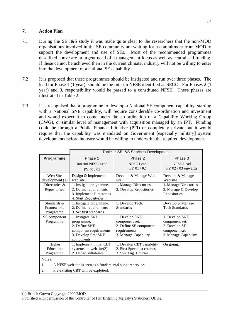
1-7
7. Action Plan
7.1 During the SE I&S study it was made quite clear to the researchers that the non-MODorganisations involved in the SE community are waiting for a commitment from MOD tosupport the development and use of SEs. Most of the recommended programmesdescribed above are in urgent need of a management focus as well as centralised funding.If these cannot be achieved then in the current climate, industry will not be willing to enterinto the development of a national SE capability.
7.2 It is proposed that these programmes should be instigated and run over three phases. Thelead for Phase 1 (1 year), should be the Interim NFSE identified as SECO. For Phases 2 (1year) and 3, responsibility would be passed to a constituted NFSE. These phases areillustrated in Table 2.
7.3 It is recognised that a programme to develop a National SE component capability, startingwith a National SNE capability, will require considerable co-ordination and investmentand would expect it to come under the co-ordination of a Capability Working Group(CWG), or similar level of management with acquisition managed by an IPT. Fundingcould be through a Public Finance Initiative (PFI) or completely private but it wouldrequire that the capability was mandated on Government [especially military] systemdevelopments before industry would be willing to underwrite the required development.
_______________________________________________________________________________________________(c) British Crown Copyright 2000/MODPublished with permission of the Controller of Her Britannic Majesty's Stationery Office.
Table 1: SE I&S Services Development
Programme Phase 1Interim NFSE Lead
FY 00 / 01
Phase 2NFSE LeadFY 01 / 02
Phase 3NFSE Lead
FY 02 / 03 onwards
Web Sitedevelopment (1)
Design & Implementweb site.
Develop & Manage Website.
Develop & ManageWeb site.
Directories &Repositories
1. Instigate programme.2. Define requirements3. Implement Directories4. Start Repositories
1. Manage Directories2. Develop Repositories
1. Manage Directories2. Manage & DevelopRepositories
Standards &FrameworksProgramme
1. Instigate programme.2. Define requirements3. Set first standards
1. Develop Tech.Standards
Develop & ManageTech Standards
SE componentProgramme
1. Instigate SNEprogramme.2. Define SNEcomponent requirements3. Develop first SNEcomponents
1. Develop SNEcomponent set.2. Define SE componentrequirements3. Manage Capability
1. Develop SNEcomponent set.2. Develop SEcomponent set3. Manage Capability
HigherEducation
Programme
1. Implement initial CBTsystems on web site(2).2. Define syllabuses
1. Develop CBT capability2. First Specialist courses3. Sys. Eng. Courses
On going.
Notes:
1. A NFSE web site is seen as a fundamental support service.
2. Pre-existing CBT will be exploited.

1-8
Annex A: An example of a programme to provide a Standard SNE Database Capability
1. Many aspects of the analysis indicate that there is significant requirement for a set of standardSNE components based on defined and accepted standards. It is certain that the developmentof such a capability will take a long time to accomplish and therefore work must startimmediately. The Interim NFSE should constitute or designate an authority to oversee thecreation of a national SNE capability. It should:
a. Identify and designate a set of [international] standards for the SNE capability includingthose for SNE specification, interchange, implementation and use.
b. Identify and define those SNE components that must be available and managed in order tosupport the short, medium and long term SE requirements.
c. Identify those SNE components that currently exist and make as many as possible openly,either directly or in-directly, available for use.
d. Design and set in motion a national programme to develop those components that are notcurrently available and to manage the complete SNE capability.
2. Such a national capability does not imply a requirement for a national SE WAN at this stage.Eventually the set of SNE Components developed plus a suitable SE WAN could constitute therequired ‘Salisbury Plain’.

1-9
Annex B: Synthetic Environment Web Site
A National Focus for the SE web site should be developed as soon as possible, in order to supportthe required services. Several web sites covering SEs are currently in operation and it may be thatone of these could be extended to provide required environment or a new site may be seen to benecessary. The web site could support the following services:
1. SE Education. The web site should provide a number of Computer Based Training (CBT)courses ranging from 2 to 10 minute sessions covering the basics of the use and developmentof SEs. Longer, more detailed courses could be provided, if the need for them on this mediumis subsequently identified, but such training is probably best left to more traditional courses.
Small demonstration SEs on the web site would support education and marketing of thecapability.
2. Systems Engineering Education. Courses and literature on systems engineering are wellestablished but are not necessarily mature. The best way of educating the visitor to the website on such matters is the provision of case studies.
The web site should provide an overview of system engineering concepts and how they applyto the use and development of SE and references to external sources of courses, coursewareand literature.
3. Case Studies. The web site should provide access to a number of suitable (and short) casesstudies. They may have to be taken from other (non-military) applications (e.g. aerospace,petrochemical, automotive). However, a study arising from the application of SEs to SPIshould be included as soon as possible.
4. Directories. A set of directories of practitioners, capabilities, resources, SNE components andcourses should be implemented as soon as possible.
5. Glossary of terms. A Glossary of terms should be included as soon as possible to ensure thatwe are using the same terminology.
6. Knowledge Base. A knowledge based system should be implemented as soon as is practicableand as an extension to a basic directory system. A question and answer (e.g. “Ask Jeeves”search engine) type of system may be very helpful to those requiring initial support.
7. Repository. A set of repositories for data, specifications, components and models should beimplemented as soon as is practicable. This is a longer-term requirement and may not beeconomical until suitable standards and frameworks have been in place for some time. Arepository would encourage re-use of components but would likely be expensive to implementand maintain.
References
1. MOD SE Policy paper, D/DG(R&T)/8/6/1/1 dated 7 Dec 98
2. The SECO vision for infrastructure and services for the support of Synthetic Environments.DG(R&T)/8/8/1/13 dated 1st June 1999.

���������������� ���� �� ��� ���
������������� ���� ����

2-1
An Integrated Canadian Approach toConcept Development, Joint Experimentation
and Modelling and Simulation
Dr John BovenkampDefence Research and Development Canada and
Joint Experimentation Centre Project TeamDND, Constitution Building
305 Rideau St., 8th FloorOttawa, Ontario K1A 0K2
Canada
Paper presented at the RTO NMSG Conference on “The Second NATO Modelling and SimulationConference”, held in Shrivenham, UK, 24-26 October 2000, and published in RTO MP-071.

This page has been deliberately left blank
Page intentionnellement blanche

3-1
The Establishment of the Army Simulation Centre
Lieutenant-Colonel J.L. CyrDirector Army Simulation Centre
Land Force Doctrine & Training SystemPO Box 17000, Station ForcesKingston, Ontario K7K 7B4
Canada
Paper presented at the RTO NMSG Conference on “The Second NATO Modelling and SimulationConference”, held in Shrivenham, UK, 24-26 October 2000, and published in RTO MP-071.

This page has been deliberately left blank
Page intentionnellement blanche

4-1
An R&D Strategy for the Way Aheadin M&S for the Canadian Air Force
Dr Jack P. LandoltDefence and Civil Institute of Environmental Medicine
1133 Sheppard Ave. W., P.O. Box 2000Toronto, Ontario, Canada M3M 3B9
Mr John R. EvansDirectorate Science & Technology Air
Defence R&D CanadaConstitution Building, 8th Floor
305 Rideau StreetOttawa, Ontario, Canada K1A 0K2
Introduction
The capital-equipment programme of the Canadian Department of National Defence(DND) is strongly focussed towards commercial-off-the-shelf purchases and the lifeextensions of existing systems through new technology insertions. This influences theway that DND mobilizes its resources for force development, life-cycle acquisition, andtraining when meeting capability requirements. The use of contemporary methods inmodelling and simulation (M&S) is drawing increasing attention within DND as animportant way of achieving cost-effective objectives in support of this type of capital-equipment modernization process.
Defence R&D Canada (DRDC), under the direction of Directorate Science andTechnology Air (DSTA), recently completed a study on some long-term initiatives inresearch and development (R&D) in M&S that could aid Canadian air-force objectives incapability modernization for the delivery of air power. To date, air force M&S has beenconfined largely to the purchase of training simulators, and the development and use ofoperational-research modelling tools. This paper addresses R&D issues across all of thedomains of M&S application that DRDC could undertake in meeting the different air-force capability requirements. These include:• force, doctrine and tactics development,• acquisition, operation and support of equipment, and• training.
‘Legacy’ Models and Simulations Available to DRDC
The study commenced with a compilation of legacy models and simulations having air-systems applications that are accessible to DND. Over 300 models and simulations wereidentified; many of these were developed in DRDC’s Defence Research Establishments(DREs). These legacy items were identified according to an acronym given to each ofthem, their domain of application and where they were kept for safekeeping. They werethen mapped against Military Air Usage, and Military Air Applications to establish howthey might be used in M&S to advance the air-force capital-equipment programme.
Paper presented at the RTO NMSG Conference on “The Second NATO Modelling and SimulationConference”, held in Shrivenham, UK, 24-26 October 2000, and published in RTO MP-071.

4-2
The domain of Military Air Applications relates to Canadian air-force doctrine and, assuch, it identifies the various elements that operational experience has dictated will workbest in the effective use of air power. For purposes of this study, these elements are:• Combat Air Operations
• Counter-Air (Control of Air Space)• Offensive• Defensive
• Counter-Surface (including Sub-Surface action)• Air/Land• Air/Sea
• Supporting Air Operations• Air Transport• Air-to-Air Refueling• Combat Search and Rescue (SAR) and SAR• Electronic Warfare• Airborne Early Warning & Control• Airborne Command, Control and Communications• Intelligence Support Operation• Special Operations
• Ground Support Operations• Operations Support
• Engineering and Maintenance• Environment• Intelligence• Air Traffic Control• Air Defence• Ground Defence• Nuclear, Biological and Chemical Warfare (NBCW)• Airfields Engineers
• Logistics Support• Administration• Finance• Construction Engineering• Electro-mechanical (E/M) engineering• Transport
• Command and Control
The domain of Military Air Usage encompasses the following components:• Force Development & Doctrine
• Strategic Planning & Concepts Development• Threat Analysis & Assessment• Operations & Contingency Planning• Tactics & Procedures Development• Doctrine Development

4-3
• Long Range Equipment Planning• Requirements Definition• Contender Bid Evaluations• Engineering Development• Maintenance & Logistic Support• Test & Evaluation
• Training• Procedures Training• Team Training• Mission Planning & Rehearsal• Education
These models and simulations may also be categorized according to the different levels inwhich they represent the real world:• Level 1: Operational Capability (Force on Force)• Level 2: Tactical Effectiveness (Engagements of Few on Few)• Level 3: Systems Performance (Ensembles of Devices)• Level 4: Physics-Based Models (Single Devices, Mathematical Models)
Over the years, DRDC and its DREs have developed a large number of physics-basedand systems-level models (including those of human systems) which have beenaugmented by those from departmental engineering units; consequently, there is a largeM&S database available in these two categories. A few tactical effectiveness models,e.g., few-on-few engagements, are included in the database that were developed byDND’s operational research directorates. The defence industrial sector contributed tosome of this inventory through contract work with DRDC; other models and simulationswere made available through international agreements.
By way of an example on how these entities may be used, one can envisage amissile/aircraft tactical engagement where different threats and aircraft characteristics areimplemented by legacy models and simulations to address specific issues that aiddecision making for the air force. Results from Level 4 (physics-based models) can befed upward into Level 3 (systems-level models) and then into Level 2 (tacticaleffectiveness simulations) (and vice versa if refinements are required) as computersubroutines and data tables according to the degree of complexity required.
Similarly, specific areas that are relevant to the design and use of a high-performanceaircraft such as the human issues pertinent to pilot protection and performance, cockpitenvironmental features, airframe characteristics, weapon effects, etc. could beinvestigated by reusing these legacy items.
DRDC envisages that the source codes of many of these legacy databases could be‘wrapped’ for reuse in federations (e.g., by employing High-Level Architecture (HLA))for distributed simulations with planning, research, engineering and other units within

4-4
DND and with other organizations, both national and international. By employing anobject-oriented, software programming approach (e.g., C++), new and legacy models andsimulations would be amenable to maintenance, reuse and sharing with allied defencepartners. Accordingly, by creating standardized repositories of validated legacy software,data, and environments that serve the needs of NATO, other allied concerns, DND andcommercial interests, much can be achieved in the sharing of this information. Perhaps,NATO could act as a central repository for the establishment of such a database!
Relevant Scientific Issues in M&S
The study then considered the different scientific issues that should be addressed usingM&S to aid capability modernization of the Canadian air force. These include:• Constructive simulations• Simulation-based acquisition• Low-cost simulators• Distributed-mission simulation• Technology demonstration projects• Human-systems issues
For each of these six scientific issues, a series of R&D topics were identified that DRDCcould pursue. Objectives were given in terms of:• Techniques and tools for improving the ability to simulate• Types of air-force problems that should be addressed with M&S
From this compilation of objectives, ten priority areas were identified as having particularrelevance in each of these two categories. In order to get a sense of their appropriatenessto the R&D programme and importance to air-force objectives, each of these priorityareas were subsequently assessed according to:• Importance of R&D choice• Maturity of technology• Level of internal DRDC activity• Level of activity elsewhere in Canada• Level of activity in allied countries• Infrastructure required• Impact on joint/combined operations• Potential for generating revenue• Affordability• Relevance• Risk of failure
Development of Tools and Techniques in M&S by DRDC
The study identified the following ten priority areas that DRDC could pursue indeveloping techniques and tools in M&S:• DRDC/industry exercises in constructing and using HLA federations• R&D in computer-generated forces and human-behaviour modelling in constructive
simulations• Use of object-oriented programming languages in future simulation developments• R&D in encryption technology to secure distributed simulations

4-5
• R&D in low-cost simulators for individual and team training• Develop operational-analysis capability in DREs to aid in embedding new technology
concepts in constructive simulations• Alternatives to high-cost visual displays (e.g., virtual-reality concepts)• Use of M&S in reducing costs in test and evaluation• Continue R&D of validated/verified physics-based and systems-level models in
support of evolving air-force objectives• R&D in human-systems issues that limit effectiveness of simulators (e.g., simulator-
induced sickness, motion cueing, latency issues)
Application of M&S to Air-Force Problems
The following ten technical and non-technical areas were identified as relevant forexploiting M&S in aid of air-force problems:• Develop synthetic, Canadian littoral battlespace for use in procurement of weapon
systems, and for assessing tactics and doctrine of shallow-water operations• Develop tactical aircraft environment to assist in helicopter upgrades of weapon
systems• Develop CF-18 high-performance aircraft cockpit in support of incremental
modernization and tactical-engagement training• Assist in applying M&S in human-systems integration during early stages of
equipment acquisition and upgrades• Employ M&S in developing Canadian requirements in unmanned air vehicles and
fighter aircraft• Create weapon-system-effectiveness federation for weapon selection and associated
countermeasures• DRDC participation in newly-organized Air Force M&S Working Group• DRDC participation in creating an officer-education plan in M&S• Provide advice in M&S to engineering and other relevant DND directorates• Assist in developing an effective policy for implementing simulation-based
acquisition, including pilot projects that demonstrate feasibility
Conclusions and Recommendations
This study provides suggestions and recommendations for a strategy on a ‘way ahead’ inR&D in M&S that supports the broad objectives of the Canadian air force for capabilitymodernization for the delivery of air power. It is an ambitious endeavour but necessary ifDND is to remain abreast of parallel efforts in allied countries. To implement it properlywill require on the part of DRDC:• Greater awareness within air-force directorates of DRDC capabilities in M&S, e.g.,
the extent and nature of available legacy models and simulations in the DREs• Greater internal DRDC coordination to ensure that there is not duplication of effort in
M&S amongst the DREs and other allied agencies• Acquiring an appropriate distributed-simulation network between the DREs to
promote sharing of M&S resources• Greater collaboration between DRDC and DND operational-analysis experts• Greater DRDC involvement in the use of M&S in acquisition support for technical
analysis of options, assessing contender bids, etc.

4-6
• Greater liaison between DRDC and industry to foster greater leverage of M&Sresources
• Increasing the pool of M&S experts in DRDC to promote greater usage of M&S inthe department
• Replacing current ‘stovepipe’ approach to a multi-purpose, shared environment forconducting mission-systems simulation
• Participation by DRDC in developing an appropriate organization within the air forcethat exploits the use of virtual and constructive simulations
This concludes our presentation of this study.

5-1
Italian M&S Center Project
Col. Alvino SURIANCapo Uf.Simulazione Operativa-Composizione delle Di
SMD-COIVia Papiria 365
00175 RomaItaly
Paper presented at the RTO NMSG Conference on “The Second NATO Modelling and SimulationConference”, held in Shrivenham, UK, 24-26 October 2000, and published in RTO MP-071.

This page has been deliberately left blank
Page intentionnellement blanche

6-1
SEMB Presentation
Prof Mick MansellBAE Systems
Warton Aerodome (W293H)Warton, Nr Preston, Lancs PR4 1AX
United Kingdom
Paper presented at the RTO NMSG Conference on “The Second NATO Modelling and SimulationConference”, held in Shrivenham, UK, 24-26 October 2000, and published in RTO MP-071.

This page has been deliberately left blank
Page intentionnellement blanche

7-1
Introduction to the DiMuNDS 2000Project and Demonstration
Dr. Dirk CoppietersNATO C3 Agency
HISB/ISDPO Box 174
2501 CD The HagueThe Netherlands
Joost HamersTNO Defence Research
RG 1-1, Operations Research - Army, CSSOude Waalsdorperweg 63
PO Box 96864, 2509 JG The HagueThe Netherlands
Paper presented at the RTO NMSG Conference on “The Second NATO Modelling and SimulationConference”, held in Shrivenham, UK, 24-26 October 2000, and published in RTO MP-071.

This page has been deliberately left blank
Page intentionnellement blanche

8-1
Emerging ISO Standards for the Representation ofPhysical Environmental Data
Dr. Jack CogmanThomson Training & Simulation
Gatwick RoadCrawley, West Sussex RH10 2RL, UK
Abstract
In order for standards to be effective, they have to be developed by a consensus of the users. In the case ofstandards for the representation of physical environment data, the users are both Military and Civil andoperate in a range of different domains, from modelling and simulation through to entertainment. TheSEDRIS Organization has recognised the benefits of international, commercial based standards and haschosen to work with ISO/IEC to develop standards for environmental data representation and interchange.The work of an Industry/Government team has produced a robust environmental data interchangemechanism. The related technologies include a data representation model for the physical environment(terrain, ocean, atmosphere and space), a method for uniquely classifying and identifying the objects in thatmodel and a spatial reference model to unambiguously specify locations. The task is to transpose thistechnology into International Standards.
This paper reports on the standardisation process that was selected for SEDRIS, the progress and timescalefor the publication of the related ISO/IEC standards and the impact that the standardisation process has hadon the development of SEDRIS.
Introduction
A standard, by definition, promotes stability andpermanence. The rate of technical change that weare currently experiencing, however, demandsflexibility. These conflicting factors make it difficultto introduce standards into areas of technicalchange, such as Synthetic Environments. This isparticularly true for the representation andinterchange of synthetic natural environment data.The need for a common standard for databaseinterchange has long existed in the Modelling andSimulation community, but, with the increasinguse of networked simulations and heterogeneousplatforms, this need has extended to the provisionof interoperable representations of the SyntheticNatural Environment (SNE).
SEDRIS technology (Refs. [1], [2]) has respondedto this need by developing a robust mechanismfor the representation and interchange of physicalenvironment data, i.e., ‘the real world’. This paperdescribes how that technology is beingtransposed into international standards in a waythat will allow flexibility and, at the same time,enhance the original, engineering based work tomake it of greater value to the internationalModelling and Simulation community and to usersin other domains.
The paper addresses;
1. Data representation of the Synthetic NaturalEnvironment
2. The need for standards relating toenvironmental data representation
3. Why it is difficult to interchange databaseswithout loss of information
4. The available options for standardisation
5. Current status of SEDRIS related standards
6. The impact of the standardisation process onthe development of SEDRIS
Data Representation of the Synthetic NaturalEnvironment
The Synthetic Natural Environment (SNE) is animportant, though not necessarily essential, partof a Synthetic Environment (SE). It is given thelabel ‘natural’ in order to distinguish it from othercomponents of an SE, such as synthetic forces,real equipment, simulation architecture andnetworks. In practice, a synthetic naturalenvironment will probably include many man-made features, such as buildings, roads andbridges. It may also include vehicles and othermobile objects, since they provide measurableattributes that describe the physical environment(Ref. [3]).
Paper presented at the RTO NMSG Conference on “The Second NATO Modelling and SimulationConference”, held in Shrivenham, UK, 24-26 October 2000, and published in RTO MP-071.

8-2
Figure 1 Data Representation of the SNE
The synthetic natural environment is a datarepresentation of the physical world that is usedby federated simulations in a networked exercisefor a variety of applications. These can consist ofnot only the visual, IR and radar views of theenvironment, but also models of the atmosphereand sea bed, as indicated in Figure 1.
In a synthetic environment, there can be only onedefinition of the physical environment, the SNE,and for this reason it is sometimes referred to asthe ‘Ground Truth’. The form in which the SNEdata is required for each user's run time database,however, can vary significantly. For example, thedatabase could be for generating an image on avisual, IR or radar display, or it could be a physicalmodel of the environment needed for CGF, or itcould be an atmospheric weather model. Even ifthe database were required for two visualsystems, there could still be differences in thedesigns of their respective image generators suchthat the environmental data had to be representedin different ways.
The goal that is sought after is for interoperabilitybetween federated simulations. There are manydefinitions of interoperability, but the following,adapted from Spuhl and Findley (Ref. [4]),appears the most appropriate;
‘Interoperability exists when a simulation imitatesall the necessary attributes of an event, such thatthe effect experienced by the observer isappropriate and equivalent to the same effect
experienced in another simulator or experiencedin the real world.’
The different forms of the SNE must therefore allagree with one another and provide a consistentview of the physical environment.
The Need for Standards for Environmental DataRepresentation
To achieve interoperability, it must be possible togenerate run time databases from a common datarepresentation of the environment. With referenceto Figure 1, the run time databases will need to begenerated from the data representation of thephysical environment. This will require a standardmethod for data representation and a standardmechanism for interchanging that data to theformats needed by the simulation platforms.
The generated databases will need to beconsistent, correlated and seamless.
• Consistent: The same set of terrain, featuresand attributes must be available to all users.
• Correlated: The positions of the terrain andfeatures must be correlated and the attributesof the terrain and features must be equivalent.
• Seamless: Any differences in the way that theenvironmental data has been represented
Synthetic NaturalEnvironment (SNE)
Synthetic Environment
Radar
Map Displays
Weather
Atmosphere
Bathymetry
etc.......Visual Sensor CGF
Warfare Analyses
SE Based AcquisitionOperationalEmployment
Test and Evaluation
Training and Rehearsal
Data Representation ofthe Physical Environment

8-3
must be hidden from the user. Theenvironment should appear to be ascontinuous as it is in real life.
In order to support the different ways in whichdata is represented, it is inevitable that there willbe multiple representations of the same features.To ensure that these representations are entirelyequivalent and are interpreted in the same way bysimulations, they must be unambiguously defined.Furthermore, the meaning of the data must not belost or distorted during the data interchangeprocess. To overcome these problems, SEDRISaims to provide a technology for datarepresentation and interchange that is;
• Representationally polymorphic
• Unambiguous
• Loss-less
These are not trivial objectives. The interchangeof databases between different formats withoutloss of information has proved particularly difficultto achieve. SIF/HDI, published as MIL-STD-1821in 1993, defines a standard format for databaseinterchange. It has not been as widely adopted byIndustry or Government as had been hoped. Partof the reason for this is the loss of information thatoccurs when a native database is converted toSIF. The rigid data structure can also give rise tosome ambiguities. A study (Ref [6]), for example,showed that the time saved by interchanging anexisting database via SIF, as opposed togenerating a new database, was no greater than15%.
SEDRIS technology has addressed these issuesby recognising that interchange is closely relatedto how the data is represented. In order forSEDRIS and its associated standards to be widelyaccepted by Government and Industry, care hasbeen taken to ensure that the representation andinterchange of information is as loss-less,unambiguous and flexible as possible.
Data, Information, Knowledge and Understanding
To understand why it is difficult to interchangedatabases without a loss of information, it isworthwhile examining in more detail what is meantby data, information, knowledge andunderstanding. At first sight, the terms appear tobe interchangeable, but on closer investigation, itis seen that they are part of a spectrum thatextends from noise at the low end to wisdom atthe high end (Ref.[5]). Noise becomes data whenit is possible to recognise a pattern. Databecomes information when it is combined with
other data in a way that adds meaning.Information integrated with other information canprovide knowledge. With knowledge, decisionscan be made and actions taken. If knowledge iscombined with other knowledge, it can provideunderstanding. That is, not only is it possible toknow, but also to evaluate and to anticipate. Thetransition from data through to understanding isachieved by adding value at each stage of theprocess, as shown in Figure 2.
Information
Understanding
Wisdom
KnowledgeData has;
• Coherence
• Meaning
Enables;
• Decisions
• Actions
Data
Enables;
• Anticipation
• Evaluation
Sea of Noise
Figure 2. From Data to Understanding
How does this relate to a standard forenvironmental data representation? It is relevantbecause it provides an insight as to why datarepresentation and interchange often involves theloss of information. A simulation databasecontains more than just data. It containsinformation and, in some cases, knowledge, sinceit provides meaning and allows decisions andactions to be taken. When information andknowledge are interchanged, they need to beretained as information and knowledge. As anexample, consider a window in the side of abuilding. For flight simulation purposes, thewindow can be adequately represented as atexture pattern on solid surface. For a groundwarfare trainer, however, a physicalrepresentation of the window is needed, since itcan provide cover for a sniper. Bothrepresentations are of a ‘window’, but they conveyquite different information.
SEDRIS addresses this problem by a datarepresentation model that allows multiple

8-4
representations of features; that is, by being‘representationally polymorphic’. It also assists bydefining metadata and the relationships betweenobjects in the data model. The techniques aretherefore available to preserve information, butthey need to be applied with expertise, particularlyin the process of generating standards forSEDRIS.
Selection of a Process to Standardise SEDRIS
To define the full meaning of the data that is to berepresented requires the involvement of expertsfrom the user domains. SEDRIS technology hasbeen developed by the SEDRIS AssociatesIndustry/Government team and has followed thisapproach by directly involving experts from theModelling and Simulation community. When thetechnology was sufficiently mature to betransposed to a set of standards, a process wasrequired that would allow a similar approach to befollowed. To ensure the widest possibleacceptance, it was also realised that thestandards would need to be international.
There are a number of ways in which a standardcan be generated. Firstly, it can be defined by anindustrial organisation and, through widespreaduse, be accepted as a de facto Industry Standard.The OpenFlight® database format defined byMultigen-Paradigm is a good example of such astandard. Secondly, it can be issued as a MilitaryStandard and it's use can be mandated. MIL-STD-1821, which defines the SIF/HDI databaseinterchange format, is an example of this type ofstandard, although it’s use is no longer mandated.Thirdly, it can be defined by a national orinternational standards body by a process ofconsensus. In some ways this is similar to the firstoption, since an industry standard may also besubjected to consensus agreement. Thedifference is that for a standards body, theconsensus has to be between many organisationsand/or government agencies, rather than within asingle organisation.
The SEDRIS Organization chose the third optionfor publishing standards and to use the services ofISO (International Organization forStandardization) and IEC (InternationalElectrotechnical Commission) as the preferredstandards body. ISO/IEC have established a JointTechnical Committee (JTC1), of which Sub-Committee 24 (SC24) covers standards relating tocomputer graphics and image processing.ISO/IEC JTC 1/SC 24 (abbreviated here to SC 24)has assigned the work on SEDRIS to WorkingGroup 8 (WG 8), as indicated in Figure 3.
ISO IEC
JTC 1
SC 24
WG 8
Joint TechnicalCommittee 1
Sub-Committee 24
• Computer Graphics
• Image processing
• EnvironmentalRepresentation
Working Group 8
• SEDRIS
Other Sub-Committees
Figure 3 ISO/IEC Structure
ISO standards are voluntary. They cannot bemandated, but must be determined by marketforces. Development is by consensus agreement,where consensus is defined as;
General agreement, characterised by the absenceof sustained opposition to substantial issues byany important part of the concerned interests andby a process that involves seeking to take intoaccount the views of all parties concerned and toreconcile any conflicting arguments.
SC 24 operates a partnership arrangement withexternal organisations known as a Co-operativeAgreement. This allows subject matter expertsand standards editors to work in close co-operation for the production of standards. It hasbeen successfully used, for example, in producingthe standard for VRML (Ref. [7]). A Co-operativeAgreement has been requested between JTC 1and the SEDRIS Organization.
The ISO/IEC process for generating standards isthat successive draft versions of the documentsare subjected to wider and more critical reviews.In the case of SEDRIS, working drafts are firstproduced that are reviewed only by WG 8. Whena document is considered to be sufficientlymature, it is made into a committee draft and isreviewed at the SC 24 level. When a committeedraft is considered to be complete, it becomes adraft international standard and is reviewed by allsub-committees reporting to JTC 1. The totalprocess can take between 2 and 3 years, asshown in Table 1;

8-5
Reviewed by; Elapsed timefor first version
Working Draft(WD)
WG 8 6 months
CommitteeDraft (FCD)
SC 24 18 months
DraftInternationalStandard(FDIS)
OtherTechnicalCommittees
2 – 2.5 years
InternationalStandard (IS)
Approved byJTC 1
3 years
Table 1 Stages in the Standardisation Process
Standards relating to SEDRIS
The SEDRIS Organization and the SEDRISAssociates have developed a technology for thedata representation and interchange of thesynthetic natural environment that consists of(Ref. [1]);
• A Data Representation Model, API softwareto access data in the model and a transmittalformat
• An environmental data coding specification toprovide an unambiguous description of theobjects in the data representation model
• A spatial reference model to provide anunambiguous definition of location
A standard is being produced for each of thesethree basic concepts. Since an internationalstandard must not be programming languagespecific, an additional standard that defines thelanguage binding is produced in cases wheresoftware will need to be written.
There are currently 6 standards relating toSEDRIS that are in development, consisting of;
� SEDRIS
� Part 1: SEDRIS Functional Specification
� Part 2: SEDRIS Transmittal Format
� Part 3: SEDRIS Transmittal FormatBinary Encoding
� SEDRIS language binding
� Environmental Data Coding Specification(EDCS)
� EDCS language binding
� Spatial Reference Model (SRM)
� SRM language binding
The language bindings are currently for the Clanguage only. They may possibly be extended tobindings for Java.
Current Status of SEDRIS Standard
Proposals for four new work items relating toSEDRIS, SEDRIS language binding, EDCS andSRM were submitted to ISO/IEC JTC 1 inSummer 1999. A ballot was held on theproposals, which resulted in the approval of allfour proposals in February 2000. In order toexpedite the work, the first meeting of SC 24 / WG8 was held in October 1999.
Originally, it was intended that one languagebinding standard would serve the other threestandards. It has since been realised that theEDCS and SRM should be independent of theSEDRIS standard, hence should have their ownlanguage bindings. Requests for these new workitems were submitted in July and are expected tobe approved by November 2000.
The current status of the standards and theirforecast completion dates are given in Table 2.(See Table 1 for a definition of FCD, FDIS andIS).
Status FCD FDIS ISSEDRIS Part 1:Functional Spec.
3rd WD 8/2001 4/2002 8/2002
SEDRIS Part 2:TransmittalFormat
Notstarted
12/2001 8/2002 12/2002
SEDRIS Part 3:TransmittalFormat BinaryEncoding
Notstarted
12/2001 8/2002 12/2002
SEDRISLanguageBinding
2nd WD 12/2001 8/2002 12/2002
EDCS 3rd WD 4/2001 12/2001
4/2002
EDCSLanguageBinding
AwaitApp.
SRM 3rd WD 8/2001 4/2002 8/2002SRM LanguageBinding
AwaitApp.
Table 2 Current Status

8-6
Impact of the Standardisation Process
The ISO/IEC standardisation process was chosenbecause it would subject the standards to reviewsfrom different perspectives and that these reviewswould result in enhancements to the standards. Inless than a year, some significant changes havealready been made. The user interface to theSEDRIS data reference model has beensimplified, plus the Environmental Data CodingSpecification (EDCS) and Spatial ReferenceModel (SRM) standards have been madeindependent of the standards for SEDRIS.
ISO requires that standards should not duplicateeach other. Whereas there is no technology that isdirectly equivalent to the SEDRIS datarepresentation model, the same is not true for theEDCS and SRM. The Environmental Data CodingSpecification (EDCS) addresses topics that aresimilar those for ISO 19110: Feature CataloguingMethodology, being developed by ISO TC 211,and to the Feature and Attribute CodingCatalogue (FACC) published by DGIWG (DigitalGeographic Information Working Group - Ref. [8]).The Spatial Reference Model (SRM) addressestopics that are similar those for ISO 19111: SpatialReferencing by Co-ordinates, being developed byISO TC 211. To minimise any duplication of thework being performed, liaisons have beenestablished with both ISO TC 211 and DGIWG.While this will no doubt slow down the pace atwhich the standards can be produced, it is anessential activity that should result in enhancedstandards being produced by all threeorganisations.
Within SC 24 / WG 8, the immediate effect hasbeen to separate the standards for EDCS andSRM from those for SEDRIS. While SEDRISneeds both the EDCS and SRM, neither EDCSnor SRM need to depend on any element ofSEDRIS. They now have independent languagebindings and the naming conventions have beenmodified to remove any references to SEDRIS.
For the SEDRIS data representation model, theread and write APIs have been rationalised andcombined. This is an improvement that could havehappened anyway, but was triggered by thereview of the working draft for the SEDRISfunctional specification, at which the opportunityfor rationalisation was highlighted.
SI units have been adopted for the EDCS. Notonly does this provide conformance with anexisting ISO standard, but the elegance of the SIsystem of units will add clarity to the EDCS.
The naming of enumerated types in the EDCShas been extensively revised to removeambiguity. Many other changes have beenrecommended at WG8 standards reviews. Thesechanges will be incorporated firstly into theSEDRIS baseline release and secondly into theassociated draft standards to ensure a co-ordinated update.
Conclusions
The SEDRIS technology for the representationand interchange of environmental data has beensubjected to many years of critical feedback bythe Industry/Government team known as theSEDRIS Associates. The feedback has beenprimarily from the Modelling and Simulationcommunity. Since October 1999, SEDRIS hasbeen subjected to even wider critical feedbackfrom the international standards bodies thatcomprise ISO/IEC. This has forced the SEDRISOrganization and ISO/IEC JTC 1/SC 24/WG 8,working under a Co-operative Agreement, to takeinto account perspectives that are internationaland are from communities outside the scope ofModelling and Simulation including, in particular,Geographic Information/Geomatics.
The effect of the standardisation process hasbeen to generate additional revisions that need tobe made to SEDRIS. While this process will takeof the order of 2 to 3 years, the end result will beenhanced products. In line with the originalobjectives, the information that will be lost in therepresentation and interchange of environmentaldata will be minimised and the ambiguities will beremoved or reduced. When this has beenachieved, then it is expected that the InternationalStandards based on SEDRIS will be used by allapplications requiring a data representation of theSNE. By adopting an approach that requires aconsensus among a broad spectrum of users, thestandards will be used because they will be fit forpurpose and will be supported by bothGovernment and Industry.
About the Author
Jack Cogman is a Senior Staff Engineer atThomson Training & Simulation, based at Crawleyin the UK. He is currently the Convenor ofISO/IEC JTC 1/SC 24/WG 8, the working groupassigned to the task of transposing SEDRIStechnology into International Standards.

8-7
References
[1] Extensive documentation is available from theSEDRIS Web Site; http://www.sedris.org
[2] The SEDRIS Development Project, Paul G.Foley, Farid Mamaghani, Paul A. Birkel,(Available from the SEDRIS Papers listed onthe SEDRIS web site – see Ref [1])
[3] ‘SNE Conceptual Reference Model’, Paul A.Birkel, 98F-SIW-018, SIW Conference,September 1998.
[4] Fidelity in Modeling and Simulation, LesterFoster, 97S-SIW-073, SIW Conference,March 1997.
[5] Chapter 13, ‘Birth of the Chaordic Age’, DeeHock, ISBN 1-576-75074-4, Berrett-KoehlerPublishers Inc., 1999.
[6] ‘Visual Simulation Database Facility (VSDBF)Feasibility Study’, Phase 2 Final Report, 56251 234-179, March 1999. A study performedby LMIS and TT&S on behalf of UK MoDOR43 (Air).
[7] ISO/IEC 14772-1:1997, VRML97, The VirtualReality Modeling Language.
[8] Further information on DGIWG is available at;http://www.digest.org/

���������������� ���� �� ��� ���
������������� ���� ����

9-1
Promoting Re-use in Synthetic Environmentsby Developing Generic Components
Rob SmithSynthetic Environments Manager
Matra BAe DynamicsPB 230, Six Hills Way
Stevenage, Herts SG1 2DAUnited Kingdom
Tel: +44 (0) 1438 75 3678Fax: +44 (0) 1438 75 6293
Email: [email protected]
Paper presented at the RTO NMSG Conference on “The Second NATO Modelling and SimulationConference”, held in Shrivenham, UK, 24-26 October 2000, and published in RTO MP-071.

This page has been deliberately left blank
Page intentionnellement blanche

10-1
The Use of DIS and HLA for Real-Time,Virtual Simulation – A Discussion
Mr. Joseph SteelRoyal Military College of Science, Cranfield University,
Shrivenham, Swindon, SN6 8LA, [email protected]
ABSTRACT: The ability of simulation systems to exchange information is of paramountimportance in a synthetic environment. Both Distributed Interactive Simulation (DIS) and the HighLevel Architecture (HLA) via the Run Time Infrastructure (RTI) facilitate this information exchange.However, they do so in very different ways.
This paper compares and contrasts the two methods in their use in a real-time syntheticenvironment (SE) involving a number of virtual and constructive simulations. The paper ispresented in the form of a conversation or debate between two system developers: one who believesthat DIS is sufficient for the task at hand, while the other is a firm believer in HLA. Theconversation is based upon the experiences of the two developers, in using their respective methodfor a synthetic environment incorporating a number of generic vehicle simulators and a semi-autonomous force generator.
This conversation revolves around a number of issues that occur when using each of the twomethods. These include the initial learning curve; ease of implementation; problems of inter-operability between other systems within the SE and the facility for system re-use.
Introduction
To allow distributed systems to communicate, wenow have two standards: Distributed InteractiveSimulation (DIS) and the High Level Architecture(HLA) via the Run Time Infrastructure (RTI).HLA-RTI is very much the newer of the two and,to some extent, has been developed to solve theproblems of DIS. However, are these problemserrors in perception of using DIS and does HLA-RTI, in fact, bring it’s own problems that need tobe resolved.
This paper investigates a number of fundamentalissues that occur in distributed, real-time, virtualsimulations when using DIS and/or HLA-RTI.These issues are:
• The ease of learning to use either DIS orHLA,
• The ease of implementing systems usingeither DIS or HLA,
• What inter-operability issues are there,• How does DIS and HLA promote system
re-use.
This investigation is presented in the form of aconversation between two fictitious systemdevelopers, DISman and HLAman. In reality,these issues are the result of actual exercises
performed in the Simulation & SyntheticEnvironment Laboratory at the Royal MilitaryCollege of Science, Cranfield University,Shrivenham, UK. Of particular interest to thispaper, the laboratory contains a number of genericvehicle simulators (crewstations [1]) and acomputer-generated force application [2]. Thecrewstations can be configured to use either DIS orHLA to communicate and, although the CGFapplication is solely DIS based, the laboratory hasa DIS-HLA Gateway [3] that allowscommunication to occur with the HLA version ofthe crewstations.
It could be argued that, HLA is the future fordistributed simulation:
“HLA establishes a common high levelsimulation architecture to facilitate theinteroperability of all types of simulationsand models among themselves and withother Command, Control, Communication,Computer and Intelligence (C4I) systems aswell as to facilitate the re-use of M&Scomponents.” [4]
However, there are a number of DIS basedsystems in operation throughout the world and it isstill used as a fundamental building block ofdistributed simulation systems. In the US, the
Paper presented at the RTO NMSG Conference on “The Second NATO Modelling and SimulationConference”, held in Shrivenham, UK, 24-26 October 2000, and published in RTO MP-071.

10-2
Close Combat Tactical Trainer (CCTT), is the firstof the Combined Arms Tactical Trainer (CATT)family of virtual trainers. It will train armour,cavalry, and mechanised infantry platoons on theircollective tasks.
In the UK, the Combined Arms Tactical Trainerwill network 66 vehicle specific simulators at theBritish Army's Tactical Training Centre,Warminster. An identical system will be based inSennelager, Germany. These two systems will beable to either work independently or jointly via awide area network.
These two systems, the US CCTT and the UKCATT, are both currently DIS based. It should benoted that there are plans to migrate the US CCTTto use HLA-RTI.
In addition, the Royal Australian Navy is in theprocess of linking together a number of commandtraining simulators at the Maritime WarfareTraining Centre, HMAS Watson, Sydney. Theprogramme manager for this contract has stated:
“We will link these trainers using DISprotocol simply because we are notconfident that HLA is significantly matureor indeed, where the technology is going.We do not want to be on the bleeding edgeof technology.” [4]
Therefore, although there is a considerable drive,especially in the US, to use HLA, DIS is by nomeans dead.
Implementation
In this first section, our fictitious systemdevelopers discuss the implementation of DIS andHLA-RTI based applications. They discuss theavailable learning material, what computerlanguages may be used and the available systemsarchitectures that the two frameworks allow.
DISman: There is so much to HLA-RTI that theinitial learning curve is very steep.
HLAman: There is a learning curve, the steepnessis very dependent on an individuals background. Ifthey have done very little programming then yes,the curve is steep, but even a rudimentary programknowledge is often sufficient. To ease the task ofdeveloping an HLA-RTI based application, thereis an enormous amount of material on the conceptsof HLA [5], and programming issues using theRTI [6]. How many RTI-based applications beganlife as the HelloWorld or FoodFight++applications? Indeed, there are training courses in
the US and Europe [7] and at least one book onusing HLA-RTI is now available [8].
The only published documentation on DIS are thevarious standards [9, 10, 11, 12, 13].
DISman: However, not only do these standardsdefine DIS, they also tell one how to use it. Inaddition, DIS can be programmed in any computerlanguage, under any operating system that allowsbasic network communication. Thus, you can writea DIS based application in Visual Basic, C orDelphi running under Microsoft Windows, or evenTcl/Tk on some obscure UNIX system.
This is because the structures of the DIS PDUsreadily translate into records or structures in therelevant language. Once these structures have beendefined, it is a relatively straightforward matter topopulate them with the required data. Thestandards specify the format of this data and definethe various enumerations. For example, in adetonation PDU, the different detonation resultsare all clearly documented, so that we candifferentiate between an entity impact and anentity proximate impact.
If you are going to use HLA-RTI, you need aknowledge of the language in which the RTIimplementation has been written. This is typicallyJava, C++ or Ada. In addition, the availability ofthe RTI can restrict your choice of platform or visaversa, that is the platform restricts your choice ofRTI. For example, the US CCTT system ismigrating to use HLA-RTI. However, their onlychoice of RTI is that supplied by DMSO as there isno other RTI for the AIX operating system thatCCTT uses [14].
HLAman: The choice of programming languageis restricted to the language bindings for the RTI.The DMSO RTI is available for Java, C++, Corbaand Ada 95 and for quite a range of operatingsystems, including Microsoft Windows 98/NT,Sun Solaris, SGI Irix and Linux. Other languagescan be used if a wrapper is written. For example,there is no reason why the C++ binding could notbe used from Delphi.
That said a deep understanding of the intricaciesof, for example C++, is not required to get up andrunning. The FoodFight federate example codethat can be downloaded from the DMSO HLA website [5], does not make extensive use of thelanguage features of C++. A basic understandingof classes is all that is required, and this can oftenbe picked up in the first few chapters of most C++books.

10-3
You said that DIS could run “under any operatingsystems that allows basic networkcommunication”, although this is true, theapplication developer must create all the necessarynetwork interfaces. In addition, they must be abledeal with the receipt of incoming network traffic.This requires the design of some form of networkpolling or parallel thread mechanism. The RTI,whichever version is actually used, handles all ofthis for you. It acts almost as part of the underlyingoperating system of the host computer. In fact, itcan even be thought of as an addition to theoperating system, extending the systemscapability. In addition, HLA-RTI supports theability to not have distributed systems, but havethe federation running on a single machine.
In terms of development, as in any object-orientedprogramming language, careful system design iscrucial and this is the case when using HLA-RTI.The design of the Simulation Object Model (SOM)and the Federation Object Model (FOM) arecrucial to the operation of the federation. Thistypically requires a new way of thinking about theproblem, whereby we divide it into a number ofcomponents.
Let us consider an example: The simulation of atank moving over a terrain surface. As the tankmoves there is some form of user input that allowsthe turret and gun to move.
When using DIS, it is typical that one computerwould execute the whole tank model: thedynamics model of the vehicle moving over theterrain surface and the modelling of thearticulation of the turret and gun. This forms amonolithic system brought about by therequirements of DIS and not the model. Thisrequirement is that all of the informationpertaining to a single entity must be passed withina single Entity State PDU.
Is it possible to build a more modular system, butstill using DIS? Possibly, for example, we couldhave two separate systems simulating our tankwith their information coming together into asingle PDU at some time. We could use a small,local network to allow this, as shown in Figure 1.
Figure 1: Distributed Entity Simulation
Here, the two systems A and B communicate witheach other using their own private network. Thiscould use DIS or a completely different protocol.In such an arrangement, System B would receivethe positional information of the entity fromSystem A and add-in the articulation informationfor the turret and gun. The complete recordstructure could then be broadcast to the remainderof the network.
So there is a workable solution for simulatingcomponents of an entity using DIS. However,HLA-RTI allows a much more logical, compactand consistent structure to be built, whereby wemake use of a component architecture. Kuhl et al.[8] states:
“The HLA is fundamentally an architectureto support component-based simulation,where the components are individualsimulations.”
Thus in our example of the tank simulation, wecould have one simulator or federate, publishinginformation on the position of the vehicle, and asecond federate publishing the articulationinformation of the turret and gun. Thus, we havetwo distinct components for our single entity. TheRTI will handle the distribution of the informationto the other systems for us.
This ability to build systems from componentscomes about by the ability to use attributes of anobject as distinct items of data. We are no longerforced into each simulator issuing a completelyvalid data record containing everything about aparticular entity. If we are unable to providecertain pieces of information then we are able torestrict what we make available.
We can draw an analogy between DIS and HLA-RTI with C and C++. In C, programs consist of aset of functions, which typically have globalscope. In DIS, we can think of each PDU as beinga function, with the PDU fields being the functionarguments. Thus, when a system sends or receivesa PDU, it is as though a function has been called.In such a case, all of the function arguments mustbe valid, and similarly all the data in each PDUmust be valid.
In C++, we have the concept of a class as a meansof encapsulating data and functionality within anobject. In HLA-RTI, we can think of each objectin a federate, as one of these base classes. Theinterface to an object is defined by a set ofattributes, much like the public data members of aclass. These attributes are made available to therest of the federation by the publish and subscribemechanisms. How an instance of an object
OtherSystems
SystemB
SystemA

10-4
manipulates these attributes, that is, theimplementation, is hidden from the other federates.Any working variables that the object may use areanalogous to the private data members in a class.Such data members are not exposed outside of theclass and thus cannot be accessed. Similarly, theworking data of a federate object is not available toother federates. Thus, as in a program that makesuse of this object–oriented design, we have theidea of components, and we build our wholesystem by defining interfaces between thesecomponents.
Interoperability
In this second section, our developers discussissues that occur when using the two frameworksas a means of allowing interoperability bydiscussing the benefits and deficiencies of the twosystems.
HLAman: One of the fundamental requirementsfor inter-operability is that whatever you use toexchange data, it must be done reliably. With DIS,this is not the case.
DISman: This is often quoted as a reason not touse DIS, but is it true?
In a DIS-based exercise, there is no central server(either in the form of hardware or software) andsystems may join and leave at any time. Thus, noone system is aware of any other system in thenetwork. Due to this, one system cannot sendPDUs explicitly to any other system, in a“reliable” fashion. This would require a unicastmechanism such as the Transmission ControlProtocol (TCP). What typically happens, whenusing DIS, is that a system broadcasts PDUs overthe network. When sending data packets usingbroadcasting there is no explicit destinationaddress specified in that packet. Thus, there is noway that the sender of the packet can determine ifany recipient received the correct data. Thisbroadcasting mechanism uses the User DatagramProtocol (UDP).
Therefore, the “unreliability” of DIS is due to the“unreliability” of UDP. So rather, than say DIS is“unreliable”, what we really mean, is that there isno guarantee of delivery of data packets.
How good is this best-effort approach? A simpleexperiment, which we performed in the laboratory,can give us an idea: In a local area network of fivemachines, each machine sent 3,000,000 packets ofdata, with each packet consisting of 1024 bytes.The packets were sent at an interval of 10ms. Anadditional machine read the data, and verified the
contents and packet order. Of the 15,000,000packets sent, none were lost and they all arrived inthe correct order. Now clearly, the next packetmay be lost or arrive after some other packet.However, this is not truly “unreliable”.
HLAman: You mentioned that DIS has no centralserver and that no one system is aware of anyother. This brings about one of the fundamentalproblems of DIS - the heart-beat Entity StatePDUs. These PDUs are issued, typically at 5sintervals, when the state of an entity is not evenchanging. There are two main reasons why theseheart-beat Entity State PDUs are issued:
• When a system joins the exercise, it willeventually hear about all of the entitiescurrently present,
• Each system can assume that if it hearsnothing about a particular entity for aperiod of time (the time-out period), thenthe system can remove that entity. Thisallows for the system that owns that entityto leave the exercise at any time.
Macedonia et al. has analysed an actual trainingexercise at the US Army National Training Centre,Fort Irwin, California, involving 2,191 entities[15]. During 10 hours of exercise, one third ofthese entities did not move and as the exerciseprogressed, one half became disabled and stoppedall movement. However, each of these entities stillissued a heart-beat Entity State PDU at a regularinterval.
In another recent DIS exercise [16], involving 45entities, of 10,982 Entity State PDUs issued, 3,060(approx. 28%) contained no new information.
These extra PDUs do nothing but remove vitalnetwork bandwidth.
When using the HLA-RTI, each federate activelyjoins and resigns from the federation. Whenjoining a federation, a federate can notify otherfederates that they should supply object stateinformation, so that it can obtain the currentground-truth. Similarly, when a federate resignsfrom the federation, it does so in a controlledfashion, informing the other federates via the RTI.Because of the passive nature of DIS, that is, nosystem actively joins or resigns from an exercise,there is this need for these heart-beat PDUs.
However, these are infrequent situations.Obviously, they do occur, but typically, once asystem is a member of an exercise, it will remainso for the duration. Yet these heart-beat PDUs areissued throughout the exercise, and so the whole

10-5
exercise is being penalised simply to handle theseinfrequent situations.
DISman: Although, it is true that these heart-beatPDUs are an overhead, their frequency and thetime-out period can be adjusted. The DIS standarddoes not dictate what these values should be.
This perceived problem could be greatly reduced.We could add an additional PDU to our set; onethat is issued by a system as it joins the exercise.On receipt of this PDU, other systems would thentransmit an Entity State PDU update for all of theirentities. In addition, proper use of the DeactivatedState flag in an Entity State PDU should be used toindicate that entity can be removed.
By implementing these two methods, systems canextend the time-out period and greatly decrease theheart-beat frequency and thus remove the heart-beat PDU overhead.
What we should also remember is that, theadditional functionality of HLA-RTI is not forfree. The simplicity of DIS imposes little overheadon the host machine. It is true that each DISsystem will receive all the PDUs from every othersystem. This can impose a significant processingrequirement on the host CPU. The classicexample, is when we have a number of ships at seaand tanks on land that are outside the range of anyform of contact. However, they still receiveinformation pertaining to one another. This isbrought about by DIS not having any datadistribution mechanism (DDM). That said, it is notimpossible to implement a DDM using DIS.Indeed, Macedonia et al. [15] consider havingspatial, functional and temporal classes, wherebyentities that have similar properties are membersof one of these classes. Only entities within thesame class exchange information. Thisfunctionality acts as an intermediary layer betweenthe DIS PDUs and the network.
There has been considerable work in this area [17,18, 19] and even the DIS standard talks aboutpossible future capabilities:
“It may not be necessary that allparticipants receive all PDUs of anexercise. Mechanisms to allow for efficientuse of network resources may includefiltering PDUs at various locations in thenetwork, data compression schemes, andsending only changes in the PDUinformation rather than the entire PDU.Multicast addressing schemes andprotocols will be used to create and controlgroups where PDUs are only sent tomembers of that group. The multicast
mechanisms are currently being developedand will be specified in the areas ofcommunication architecture, networkmanagement, and simulation management.”[10]
You mentioned in the previous section that theRTI:
“… acts almost as part of the underlyingoperating system of the host computer. Infact, it can even be thought of as anaddition to the operating system, extendingthe systems capability.”
However, that in it self is a problem. The use ofthe RTI poses a number of questions:
• How does an RTI work?• Do they all work in a similar way?• What is the benefit of using one RTI over
another?• We can use either Mäk’s RTI [20] or the
DMSO RTI [21] in the laboratory, butwhich is better?
Mäk claim that their RTI is optimised for real-timeoperations, and yet they state that:
“However, since the Mäk Real-time RTIdoes not implement all services, it ispossible that it may not meet requirementsfor a particular federate.” [20]
This sounds very dangerous. As a developer, Iwant to know what is going on.
HLAman: There are a number of RTIimplementations that one could use. At the presentmoment, the documentation of the internalworkings of an RTI is difficult to come by.
In terms of performance, research is being done.Graffagnini [22] and Wuerfel and Olszewski [23]have consider what we mean by performance andhave produced metrics. In addition, Wuerfel andOlszewski [23] have produced results using theirmetrics for the DMSO RTI 1.3v5. Oesterreich etal. [24] have developed an RTI evaluation tool andproduced results for the DMSO RTI 1.3NG.Indeed, on the DMSO HLA web site [5] a tool setfor benchmarking the performance of an RTIimplementation can be downloaded for a variety ofoperating systems.
In addition, Pullen and Kakarlamudi [25],Fujimoto and Hoare [26] and Sjöström et al. [27]have investigated the performance of a number ofRTI implementations.

10-6
There has been an on going debate recently onhaving an open-source policy for RTI technology[28]. This would allow developers to exchangeideas, develop new RTI implementations makingimprovements and optimisations.
To some extent, performance issues aside, the RTIimplementation is immaterial. The RTI is anothercomponent within the federation. As such, it canbe replaced without affecting the actual federates.As Kuhl et al. [8] state:
“… the [RTI] layer insulates the federatefrom changes in technology that may bereflected in the RTI, If the RTI must bemodified to accommodate a new kind ofnetwork, the federate is unaffected.”
We saw that a federate only exposes to the outsideworld a defined interface, that is its SOM. Theinternal workings of the federate are completelyhidden. In a similar way, the RTI also presents aninterface to the federate via the FederateAmbassador and the RTIambassador. In doing so,the internal workings and state of the RTI ishidden.
Reuse
In this final section, our two developers discusshow systems developed using DIS and HLA-RTIcan be re-used.
DISman: When using DIS, I can add mysimulator into any exercise that is using the sameversion of DIS. The one potential interoperabilitydifficulty is the non-standard enumerations,particularly for the entity types. However, we dohave a reference document that suggests valuesthat we could use [13]. In addition, we canexchange between the participants the list ofenumerations and types prior to the exercise.
The problem with HLA-RTI is that for re-use theFOM must be the same.
HLAman: That is not strictly true. Kuhl et al. [8]state that:
“The FOM is the vocabulary of the dataexchanged through the RTI for an executionof the federation”
Thus, for a federate to be able to be re-used, thevocabulary of the FOM must contain thevocabulary of the federate. Thus we can grow theFOM to allow new federates into the federation,but still be able to make use of older federates.
It is the hierarchical nature of the classes in afederation object model that allow it to grow. Wecan derive new classes extending the objecthierarchy to make use of new federates, but leaveunaffected the older federates. This is one of thegoals of HLA – to protect federates from change.As Kuhl et al. [8] state:
“… federates that were written to expectand use certain object and interactionclasses can continue to use them even if theFOM is extended with subclasses not thereoriginally.”
DISman: In this case the vocabulary of the newFOM must still contain the same words as requiredby the old federate. Thus, for example, an attributecalled position must still be called position, andthe co-ordinate system used, must still be thesame. As you mentioned, the class hierarchy canbe extended, but if it is changed dramatically, thento allow an old federate to use this new FOM,there may be significant code changes required. Asan example, the IST HLA Gateway [29], wasdeveloped for the version 0.5 of the Real-TimePlatform Reference FOM (RPR-FOM). Table 1shows the object hierarchy for classes directlyderived from the class PhysicalEntity as producedby the Object Model Development Tool [30].
Table 2 shows the object hierarchy from the samebase class (PhysicalEntity) in version 1.0 of theRPR-FOM [31]. As we can see, there has been anextensive change in the object hierarchy and objectnames. Although version 0.5 of the RPR-FOMwas written in its early stages of development,software written specification for this FOM wouldrequire significant changes to allow it to work withthe later version.
So although, the federation object model may beextended, care is still required as the names ofobjects, attributes, interactions and parameters arenot fixed. Nor are their types. For example, aposition attribute may consist of three co-ordinates, x, y and z. One federate may use singleprecision 32-bit floating point values, whilstanother may use 64-bit double precision values.Although these problems are not insurmountable,they need to be clearly identified and resolved.

10-7
Class 2 Class 3 Class 4 Class 5MilitaryAirLandPlatformMilitaryAmphibiousPlatformMilitaryLandPlatformMilitarySpacePlatformMilitarySeaSurfacePlatformMilitarySubmersiblePlatform
MilitaryPlatformEntity
MilitaryMultiDomainPlatformMunitionEntity
MilitaryEntity
SoldierCivilPlatform CivilAirLandPlatform
CivilAmphibiousPlatformCivilLandPlatformCivilSpacePlatformCivilSeaSurfacePlatformCivilSubmersiblePlatformCivilMultiDomainPlatform
PhysicalEntity
Civilian
Table 1: RPR-FOM 0.5 Object Hierarchy
Class2 Class3 Class4AircraftAmphibiousVehicleGroundVehicleMultiDomainPlatformSpacecraftSubmersibleVessel
Platform
SurfaceVesselHumanLifeformNonHuman
CulturalFeatureExpendablesMunitionRadioSensor
PhysicalEntity
Supplies
Table 2: RPR-FOM 1.0 Object Hierarchy
Conclusions
In this paper, we have made a number ofcomparisons between DIS and HLA-RTI in theiruse for real-time virtual simulation. We have seen,that there is the potential to improve DIS as itcurrently is. Some of these improvements mayrequire considerable work such as theimplementation of a DDM structure. However, thefrequency of the much-criticised heart-beat EntityState PDUs can be readily reduced, thusdecreasing the network bandwidth requirement.
For HLA-RTI, we have seen that its architectureeases the system development process and canease system re-use. However, issues do need to beresolved. These include the availability of RTIimplementations and the widespread knowledge oftheir workings. Additionally, although one of thegoals of HLA is the ability of federates to be re-used, there are potential problems when using afuture FOM. These problems need to be identifiedand resolved as early as possible in the federationdevelopment process.
References:
[1] Cranfield University, “CrewStation2000,User’s and Developer’s Guide”, AMOR 2000/6,Cranfield University, Royal Military College ofScience, Shrivenham, Swindon, 2000.
[2] Science Applications International Corporationand Lockhead Martin Information Systems,“ModSAF 5.0 Functional Description Document”,ADST-II-CDRL-MODSAF5.0-9800327, WebSite: http://www.modsaf.org/, 1999.
[3] McRae, J.D., “An Application which allowsDIS Simulations and HLA Federates to Interact”,MSc Project, Cranfield University, Royal MilitaryCollege of Science, Shrivenham, Swindon, 2000.
[4] Nash, T., “HLA Holy Grail or No Brainer”,Military Training & Simulation News, Vol. 2, No.2, ISSN: 1366-2309, 2000.
[5] DMSO HLA Web Site: http://hla.dmso.mil

10-8
[6] DMSO RTI Support Web Site:http://helpdesk.dctd.saic.com/index.html
[7] DMSO HLA Hands-On Practicum Web Site:http://hla.virtc.com/hop/
[8] Kuhl, F., Weatherly, R. and Dahmann, J.,“Creating Computer Simulation Systems - AnIntroduction to the High Level Architecture”,Prentice Hall PTR, Upper Saddle River, NJ 07458,USA, 1999.
[9] The Institute of Electrical and ElectronicsEngineers, Inc., “IEEE Standard for DistributedInteractive Simulation - Application Protocols”,IEEE Std 1278.1a-1998, 345 East 47th Street, NewYork, NY 10017-2394, USA, 1998.
[10] The Institute of Electrical and ElectronicsEngineers, Inc., “IEEE Standard for DistributedInteractive Simulation - Application Protocols”,IEEE Std 1278.1-1995, 345 East 47th Street, NewYork, NY 10017-2394, USA, 1995.
[11] The Institute of Electrical and ElectronicsEngineers, Inc., “IEEE Standard for InformationTechnology - Protocols for Distributed InteractiveSimulation Applications”, IEEE Std 1278-1993,345 East 47th Street, New York, NY 10017-2394,USA, 1993.
[12] The Institute of Electrical and ElectronicsEngineers, Inc., “IEEE Standard for DistributedInteractive Simulation - Communication Servicesand Profiles”, IEEE Std 1278.2-1995, 345 East47th Street, New York, NY 10017-2394, USA,1995.
[13] Institute for Simulation and Training,“Enumeration and Bit Encoded Values for Usewith Protocols for Distributed InteractiveSimulation Applications”, IST-CR-98-07, 3280Progress Drive, Orlando, FL 32826, USA, 1998.
[14] Foster, J., Assistant Project Manager, CloseCombat Tactical Trainer, Private Communication,13-09-2000.
[15] Macedonia, M.R., Zyda, M.J., Pratt, D.R.,Brutzman, D.P. and Barham, P.T., “ExploitingReality with Multicast Groups”, IEEE ComputerGraphics and Applications, Vol. 15 No. 5, 1995.
[16] Royal Military College of Science, CranfieldUniversity, “Long Haul 2000”, Network &Distributed Simulation Module, 2000.
[17] Stytz, M.R., “Distributed VirtualEnvironments”, IEEE Computer Graphics andApplications, Vol.16 No. 3, 1996.
[18] Barrus, J.W., Waters, R.C. and Anderson,D.B., “Locales: Supporting Large MultiuserVirtual Environments”, IEEE Computer Graphicsand Applications, Vol.16 No. 6, 1996.
[19] Broll, W., “Interacting in DistributedCollaborative Virtual Environments”, Proceedingsof the IEEE Virtual Reality Annual InternationalSymposium ’95, 1995.
[20] Mäk RTI Web Site:http://www.mak.com/rti.htm
[21] DMSO RTI Web Site:http://www.dmso.mil/index.php?page=70
[22] Graffagnini, J., “What is ‘true’ RTIPerformance? And how is it Measured”, 97S-SIW-114, Proceedings of the Spring 1997 SimulationInteroperability Workshop, 1997.
[23] Wuerfel, R.D. and Olszewski, J.S., “DefiningRTI Performance”, 99S-SIW-100, Proceedings ofthe Spring 1999 Simulation InteroperabilityWorkshop, 1999.
[24] Oesterreich, G.P., Chernick, J.A. and Pensell,H.W., “Development of RTI Evaluation Tool andApplication to Redstone Technical Test Center’sIR Tactical Missile Simulation”, 00S-SIW-097,Proceedings of the Spring 2000 SimulationInteroperability Workshop, 2000.
[25] Pullen, J.M, and Kakarlamudi, “PerformanceIssues for the Light-Weight RTI”, 98F-SIW-067,Proceedings of the Fall 1998 SimulationInteroperability Workshop, 1998.
[26] Fujimoto, R., and Hoare, P., “HLA RTIPerformance in High Speed LAN Environments”,98F-SIW-085, Proceedings of the Fall 1998Simulation Interoperability Workshop, 1998.
[27] Sjostrom, R., Johansson, U., and Nyberg, A.,“RTI NG and pRTI Performance for SimulatedAircraft, Real Time Updates”, 00S-SIW-058,Proceedings of the Spring 2000 SimulationInteroperability Workshop, 2000.
[28] Run-Time Infrastructure and CommunicationsForum, SIW-RTI, Web Site:http://confs.sc.ist.ucf.edu/listprocedu/index.cfm,Department of Information & LearningTechnologies, Institute for Simulation & Training,University of Central Florida.

10-9
[29] HLA-Gateway Release 3.3 User Guide, IST-TR-99-06, Institute for Simulation and Training,1999.
[30] Object Development Tool, DMSO HLA WebSite [5].
[31] Shanks, G., “RPR-FOM, Real-Time PlatformReference Federation Object Model, Version 1.0(Draft 2)”, Simulation Interoperability StandardsOrganization, 1999.
Author BiographyJOSEPH STEEL received a BSc from theUniversity of Wales in Mathematics and it’sApplications in 1987. He received a MSc inDefence Modelling and Simulation from CranfieldUniversity in 1998. Currently Mr. Steel is a SeniorResearch Officer at the Royal Military College ofScience, Cranfield University where his researchinterests are in the use of virtual reality fortraining, distributed simulation using DIS andHLA and real-time computer graphics.

This page has been deliberately left blank
Page intentionnellement blanche

11-1
NATO Long Term Scientific Study (LTSS/51)
on Human Behaviour Representation
(SAS-017)
Uwe K.J. Dompke
ITISat The Federal Armed Forces University Munich
Werner-Heisenberg-Weg 3985579 Neubiberg
GermanyTel.: x49-89-6004-2826FAX: x49-89-6004-2268
E-mail: [email protected]
Keywords:NATO, Computer Generated Forces, CGF, Long Term Scientific Study, LTSS,
Human Behaviour Representation, Staff Level Decision Making
ABSTRACT:
NATO LTSS are held to give a forecast on technological developments in specific areas with their impacton military operations and to give recommendations for future research activities.The paper will give an overview on the results of the LTSS for Human Behaviour Representation. Thisincludes a definition of the term Human Behaviour Representation as used by the study team, an over-view on the state-of-the-art, a discussion of applications in NATO, and the technological forecast. Therecommendations for future research activities as a result of the LTSS symposium will close the paper.
Paper presented at the RTO NMSG Conference on “The Second NATO Modelling and SimulationConference”, held in Shrivenham, UK, 24-26 October 2000, and published in RTO MP-071.

11-2
1. Introduction
Long Term Scientific Studies (LTSS) are conductedby the NATO Research and Technology Board (R&TBoard). The purpose of these studies is to provide areport on technological implications to military opera-tions in the next 10 to 15 years and to give researchplanners recommendations.
Human Behaviour Representation is a topic that is ref-erenced in a number of applications like DecisionSupport Systems (DSS) in operational planning, therepresentation of specific cells in a Computer AssistedExercise (CAX), closed simulation systems for analy-sis and acquisition purpose that can be used withoutthe engagement of operational people. The adequateimplementation and operational usefulness of such arepresentation will help to develop more cost-effectivesimulation systems and better decision support systemsin the future.
So the use of such tools is not limited to one specificapplication area. They could be used in the operationalCCIS, as analysis tools, or in the support of ComputerAssisted Exercises or in supporting the acquisitionprocess of military systems. Therefore the LTSS willhave a wide impact on any such military planning.
The research and development of the technologiesneeded for HBR is done at universities as well as byindustry. But the main part of developing strategies toget the needed operational know-how and the means toimplement this knowledge is left to research and de-velopment to be conducted by the military communityitself being therefore a highly interdisciplinary task.
In Chapter 2 the purpose and study procedure of anLTSS is explained. A definition of Human BehaviourRepresentation as used by the study team will be givenin Chapter 3. Chapter 4 discusses possible applicationsin NATO. The technology forecast of the identifiedtechnologies is shown in chapter 5 as roadmaps start-ing from the state-of-the-art to 10 to 15 years ahead.Chapter 6 summarizes the main recommendationsgiven by the study team.
2. Long Term Scientific Study -Purpose And Study Procedure
Figure 1 shows the NATO Research and Technologyorganisation. The Research and Technology Board(R&T Board) reports to both the Conference of Na-tional Armaments Directors (CNAD) and the MilitaryCommittee. The R&T Agency supports the board in itswork. The six panels and the NMSG are reporting tothe board.
The Technology Group "Studies Analysis and Simula-tion" (SAS) under the R&T Board conducts LongTerm Scientific Studies (LTSS) to
• provide a report for the use by NATO andnational authorities on technological implica-tions to military operations in the next ten tofifteen years and to
• provide research planners with recommenda-tions.
This means that technologies needed for a specificmilitary task (e.g. for maritime operations or Computergenerated Forces) are identified and their developmentin the future is evaluated.
On the other hand, military requirements for the futureare identified and the application of technological.
3. Human Behaviour Representation(HBR) - Definition
"Human Behaviour Representation" is used as a ge-neric term to refer to computer representations of hu-man behaviour in simulations. In the Final Report of
SAS Studies, Analysis, Simulation IST Information Systems TechnologySCI Systems, Concepts and integrationAVT Applied Vehicles TechnologySET Sensors and Electronics TechnologyHFM Human Factors and MedicineNMSG NATO Modelling & Simulation Group
Figure 1: NATO R&T Organisation
R&T Board
SAS SCI
R&T Agency
CNAD(Armament)
MilitaryCommittee
IST SET
HFM AVT
Pan
els
NMSG

11-3
the study “Human Behaviour” is defined in followingway:
Human behaviour (B) is a purposive reaction of a hu-man being (P) to an idiosyncratic meaningful situation(S).
Formally expressed: B= f (P,S). In words: the ob-served variability in behaviour is attributable to differ-ences in the person’s characteristics, to differences inthe situation and/or to the interplay of both.
• Mathematically spoken: the variation in themeasured behaviour can be explained by thevariation in P, the variation in S andinteraction between P and S (measurementerror not taken into account). This definitionimplies that human behaviour:
• Is a change from one state into another state(bodily and/or mentally);
• is always goal-oriented (but not necessary in aone to one relation)
• is a reaction to an external observablestimulus or to an internal covert stimulus,
• has three interrelated components: acognitive, a psycho-motor and a socio-af-fective component
• is an integration of several physiological andmental processes
• is individualised because each individualinterprets the objective characteristics of thesituation.
• Is neither necessary “rationale” nor the mostappropriate reaction under givencircumstances.
4. Future Military Environment andApplications of HBR
NATO’s first mission is still Article 5 Operations. Sothe use of HBR should be considered in this environ-ment to support military applications. Besides Article5 Operations NATO has to conduct Crisis ResponseOperations. Especially in applications to support theseoperations HBR will play a major role.
Application areas for HBR are:
• Instruction, Training, Exercise
• Defence Planning
• Support to Operations
• Akqusition
4.1 Instruction, Training and Exercises
The goal of instruction and training is to learn newskills and improve specific skills in individuals andteams. In order to support these tasks, it is necessary todevelop a model of the subject of the instruction andtraining (the trainee or group), a model of the instruc-tor and models of the inanimate systems, other humanor human-operated platforms that the trainee(s) inter-act with. The model of the instructor includes evalua-tion or performance measurement models and modelsof the various strategies that can be applied to achievethe knowledge transfer objectives. All these modelsare required for any form of instruction and training. Inorder to automate these models, they need to be madeexplicit and it is necessary to develop a suitableframework for HBR.
Given the growing need to provide effective training,the limited resources available to achieve the knowl-edge transfer objectives and the increasing complexityof military tasks, the need for automated formal repre-sentations of human behaviour is pressing. The avail-ability of the various models described above is essen-tial to support the concept of providing instruction andtraining for individuals and for teams on an any time,anywhere, on demand basis. It will also allow the sametraining standard to be achieved in less time through abetter evaluation and feedback capability and throughthe application of more diverse scenarios.
An improved level of training will also benefit the ef-fectiveness of live training, since individuals andteams, trained in simulated environments, will startwith an increased skill level. Considerable associatedside benefits are the reduced impact on the environ-ment and the increased effectiveness of deployingcostly resources. Live exercises will actually becomemore cost-effective because richer scenarios contain-ing more elements of the environment can be ad-dressed in terms of personnel, artificial and naturalcomponents.
Finally, the availability of an automated instructionand training environment that includes effective mod-els of the trainee(s), the instructor and the elements ofthe real world that they interact with will allow con-tinuous training to take place. It would provide everyindividual and team performing a military task tobenefit from a virtual instructor that is continuouslymonitoring performance and that can provide a just-in-time rehearsal capability.

11-4
Exercises are aimed at maintaining and applying ac-quired skills. They also serve to generalise knowledgeand increase the ability of individuals and teams to se-lect and apply suitable knowledge. Exercises are key tothe development of knowledge concerning the appli-cation of skills, also referred to as meta-knowledge.They typically require substantial interaction withother teams and the deployment of large numbers ofpersonnel acting as exercise facilitators in the form ofdirecting and response cell staff (representing oppos-ing, neutral and friendly forces NGOs, PVO and oth-ers). In exercises, the emphasis shifts from instructionand training to a form of peer-level coaching.
The availability of automated representations of thebehaviour of the individuals and teams that the exer-cising personnel interact with, will allow exercise set-tings to be composed in a more flexible, modular man-ner. It will also allow the environment to behave over-all in a more consistent manner by removing biasesdue to level of training and experience of augmenta-tion personnel. Given that the representations havebeen developed for interoperability and scalability,variable levels of granularity could be mixed to pro-vide the appropriate level of information during theexercises.
The consistent behaviour of automated representationsand their ability to record actions and information flowwill improve the ability to provide feedback resultingin an improved capability for after-action review.
Finally, automated representations of human behaviourwill result in a reduction in staffing levels for responsecells, other forces and directing staff functions. It willalso allow the simulation environment to be used forother purposes, e.g., acquisition and decision support.It must also be mentioned that a simulated environ-ment containing these representations of human be-haviour will enable the exercising of situations thatcannot be created in a live exercising environment.
4.2 Defence Planning
Defence Planning in NATO is the identification of fu-ture requirements to address anticipated missions, fiveto fifteen years in the future. Defence Planning iden-tifies required capabilities to solve future problems.Defence Planning is subdivided into the following dis-ciplines: Force Planning, Armament Planning, Rein-forcement Mobility Planning, Logistics Planning, Nu-clear Planning, Infrastructure Planning, StockpilePlanning, Civil Emergency Planning, and CommandInformation System Planning. Of these areas, ForcePlanning and Command Information System Planningare the main areas that require HBR research.
The challenge facing Force Planners is predicting thegeopolitical changes that will occur in and beyondNATO’s Area Of Responsibility (AOR) and definingthe forces that will be required to address future op-erations. Important issues are, should NATO continueto focus on conventional military operations or shouldit prepare for cyber warfare? How many peacekeep-ing, peace enforcement, and humanitarian missionswill NATO conduct simultaneously? How far a fieldwill they be? The working group was not aware ofany models that could provide defence planners insightinto evolution of geopolitical change and which wouldthem help plan the future force structure of NATO.
The challenge facing Command Information SystemPlanners is defining command and control systems forthe wide range of contingencies operations that NATOmay undertake in the future (to include potential Arti-cle 5 and non-Article 5 missions (Crisis Response Op-erations)). Such missions may include non-NATOmilitary units and may occur outside NATO’s histori-cal AOR. In addition, for CRO missions, NATOcommand and control echelons will need interfaceswith non-governmental organizations and other entities(such as the U.N.). Command Information SystemPlanners need sophisticated organizational modellingcapabilities that will enable them to quickly investigatealternative command and control structures. Suchmodels must be sensitive to cultural differences and becapable of analysing NATO and non-NATO organiza-tions, and their interactions.
4.3 Support to Operations
NATO anticipates that in the future the pace of deci-sion-making will have to be increased in order to allowNATO forces to plan and conduct operations withintheir opponents decision-making cycle (i.e., before theopposing side can respond in an organised manner).Further, it is expected that the amount of informationavailable, in real-time, will increase dramatically andthat decision-support tools will be needed throughoutthe NATO command hierarchy in order to process thisincreased amount of information. In addition, a recenttrend within NATO has been the integration of simu-lation with C3I system, and the real-time use of simu-lation to support operational decision-making. HBRwill play a role in meeting future C3I challenges byproviding support for information integration andcourse of action generation, as well as supporting ad-vanced simulation-based tools.
To support the military user intelligent interface agentsare needed that resides on a computer where it actsboth as a personal assistant proactively tracking infor-mation and alerting users to problems and opportuni-ties and as a portal to diverse C3I systems, providingthe user with one interface with which to perform their

11-5
daily duties. In addition, interface agents may somedayfunction as coaches, providing the novice user guid-ance on how to perform a specific task and explainingthe implications of various proposed courses of action.
In addition, HBR will play a role within simulationsystems, where advanced HBR models will enhancecontingency planning, intelligence assessment, forcegeneration and deployment planning, sustainment ofoperations, and current operations. Specifically, it isexpected that inferencing and reasoning techniquesderived from HBR research will improve many aspectsof NATO operations when incorporated into decision-aids.
4.4 Acquisition
There is a great need in the design of future systems toincrease mission capability while reducing manpowerrequirements and overall cost. The challenge is toconcurrently design new organisations, equipment, andhuman tasks in a radically different context. This is adifferent problem from engineering enhancements oflegacy systems, which is the historical norm.
In this critical problem area, models of organizationsand teams are required in the early concept stages todefine possible organizational structure and designs,and simulate the effectiveness of candidate structuresin planned battle spaces.
As design proceeds, team models are needed supportconcurrent engineering of human roles and tasking (onthe one hand) and design of equipment and automationthat the acquisitions community will use (on the otherhand).
Given the lack of analogies and historical data pro-vided by legacy-based design approaches, team andorganizational models provide the only viable ap-proach to quantifying and evaluating the organiza-tional, team, and task-teamwork design of radicallydifferent future systems. A key missing capability (to-day) is finding a way to allocate roles in a quick wayand translate such design oriented models and to asimulatable representation that can interact with exter-nal simulations (e.g. synthetic battle spaces). Team-organizational models also provide a vehicle for coor-dination with hardware/software design portions of thedesign team. They allow equipment designers toevaluate the human impact of designs and design tohuman needs, from trainability and usability to plan-ning for manpower requirements and recruiting.
5. Emerging Research and Technology
5.1 Individual Behaviour Modelling
The modelling of cognitive and mental IndividualHuman Behaviour made big progress with programsdone in the last 20 years. A broad range of techniqueshave been developed and are in use. Nevertheless thereare shortcomings in modelling the effects of socio-affective factors. These modelling techniques areneeded for the application of HBR in Crisis ResponseOperations (CRO).
To represent human behaviour in a military valid andpossible exhaustive way, it is necessary to work withina defined common problem space and then to analysemission types within this space in order to derive rele-vant military tasks leading to a satisfactory executionof that mission. To focus on the modelling of relevantbehaviour, the analysis of the mission types should bedriven by a need analysis. In a second step, a particu-lar job should be described in terms of a limited set ofgeneric behaviours. Finally, this job description is tobe seen as a framework for a learning and teachingtool.
A complete model of individual human behaviourmust always contain the three domains of behaviour –cognitive behaviour, motor behaviour, and socio-affective behaviour - and take their interactions intoaccount in the execution of a military task within thedefined problem space. Because the socio-affectiveaspects of behaviour as moderators in overall behav-iour are not well understood and because the relation-ships between socio-affective behaviour and cognitiveand motor behaviour have only been addressed in iso-lated and specific circumstances, an effort must bemade in the study of socio-affective behaviour.
A taxonomy of generic tasks expressed in terms of in-dividual behaviour within the military problem spaceis necessary and includes the following: planning, in-telligence, situation assessment (Command and Con-trol), manoeuvring, target acquisition and weapon de-livery, maintaining mobility and survivability, afteraction review. The priorities of these military behav-iour tasks were determined to be the following: (1)Planning, (2) Intelligence and Situation Assessment,and (3) After Action Review. The criteria in deter-mining the priorities were (1) feasibility of determin-ing a solution in terms of technology and tools avail-able to apply to the task, (2) time required to imple-ment an approach, and (3) importance for the militaryapplication (decision maker) (see 5.1.8).

11-6
Related to the domains of application, the complexitywithin human behaviour modelling goes from opera-tions support, through exercising then to train-ing/instruction because there are in each step of thischain more components necessary to be represented inthe environment. A complete model, suited for in-struction and training, must contain a representation ofthe behaviour of the three players: instructors, student,trainee and third persons. Moreover, it is necessary,but difficult, to implement an intelligent tutoring sys-tem (ITS) and an adaptive aptitude-treatment interac-tion system (ATI), which is necessary as one movesfrom the support operations to the instruction applica-tion. For example, once a tool for operations supportto use as an aid has been developed, one must add amonitoring/observing capability to move into the exer-cise application field, and then finally, a tutorial capa-bility must be added to operate in the train-ing/instruction application area.
To meet fully the requirements of the NATO Model-ling and Simulation Master Plan, the highest prioritieshave been given to both planning and intelli-gence/situation assessment (Command and Control) todeal with the issue of information overload and even-tually lack of relevant information. These tools mustallow also for elaboration and evaluation of alternateplans and alternate courses of action. In the area ofinstruction and training, an intelligent tutorial systemis required (saves personnel, easier composition of thetraining, broad application, allows interaction, provideautomated after action review, reusable, etc.). Thesame arguments hold for after action review acrossother application domains; an intelligent observer isnecessary to take full advantage in reuse of lessonslearned and tutor when the application or exercise iscompleted.
The major advantage of automated after action reviewis the ability to keep track of the behaviour of thetrainee from the beginning of the instruction/exerciseto the end of the mission and then allow for the reviewof the actions as compared to an optimal solution. Themajor necessity for automated after action review isderived from the situation that the observer/action re-viewer is not able to deal with the entire informationspace and then recall for later review and evaluation.This data collection allows for the capability to addressthe most frequently occurring issues for the training sothat the reviewer may be focused on the issues that re-quire the most attention for review and possible reme-diation.
5.2 Team, Group and Organization modelling
Formal computational modelling of military teams,groups and organizations is currently not well devel-oped. The fields of social and industrial/organizational
psychology have yielded a number of useful conceptsthat can be exploited for military application. How-ever, the critical shortfalls are that these concepts forthe most part are informal rather than computational,and focused on civilian rather than military social en-tities.
Current military efforts in the fields of team, group andorganisational modelling are not coordinated acrossagencies and NATO countries. This lack of coordina-tion extends both to the domain of modelling and tothat of database development and archiving.
A significant improvement in a priori predictive capa-bilities and force readiness is possible through im-proved HBR of teams and organizations. This point isdriven home in the examples provided above.
No program to achieve needed improvements in mod-elling teams and organizations exists within anyNATO nation at the present time for application inmilitary simulation for instruction, training, and exer-cise, acquisition, support to operations and defenceplanning.
5.3 Process
The current state of the practice for developing HBR ismore of an art than a science. Available models aremainly R&D efforts, built for a particular application,or with a particular research idea in mind. The impli-cations of this situation are that models have limitedgeneralisability beyond their development environ-ments. This is unfortunate, since the need for humanbehaviour within simulations is increasing. To pro-mote reusability of previous efforts and to encouragecost-effective development, a more structured ap-proach to human behaviour modelling is advocated.Following conclusions related to HBR developmentfocus on knowledge acquisition, validation, compos-ability and interoperability.
Current knowledge acquisition techniques are time-and skill-intensive. On-going developments in cogni-tive architectures are emerging which may provideguidance to the knowledge acquisition process.
Nearly no program to investigate validation techniquesfor specifically representing human behaviour existswithin any NATO nation.
No agreed upon framework exists to guide research inhuman behaviour composability.
Considerable work remains to be accomplished withinthe HBR community to promote interoperabilityamong models representing human behaviour. Aframework to foster interoperability is missing.

11-7
6. Recommendations
The co-ordination of R&D programs of the differentNATO nations would help to get better results. Thisco-ordination could be organised using existing proce-dures and organisations in NATO (e.g. Research andTechnology Board and other NATO Agencies likeNC3A). Bilateral or multilateral research and devel-opment programmes which support the developmentand application of HBR will reduce costs, and achievebetter results with greater efficiency.
Recommendations must cover a breadth of topicsranging from demonstration programs to test newlyavailable technologies and interoperability/composability issues over studies to establish thefoundations for larger multinational research efforts tolong-term research programs of a more fundamentalnature.
Demonstration programs are intended to show the po-tential of already available methodology and technol-ogy to the user and on the other hand to bring the de-veloper and researcher community in contact with theuser to know more about the specific needs and re-quirements from the operational side. If such demon-stration programs are done in an open testbed that al-lows to look for interoperability and composability is-sues this approach will help to shorten the time tomake such new developments operational and to savemoney and resources through reuse.
Besides these demonstration programs on the basis ofavailable technology the conclusions driven showedthat in all areas for HBR is still a need for basic scien-tific research that is not done by the commercial com-munity. Even if these programs will need a longer timeto lead to operational applicable system, the benefitsmake it worthwhile to start now.
Following recommendations with highest priority werederived from the discussions:
• Establish an NATO RTO ExploratoryTeam to build up a virtual institute forresearch on human behaviour modelling(SAS-Panel, HFM-Panel, IST-Panel,NMSG)
• Establish a NATO RTO Specialist Teamon a research plan for team, group andorganizational modelling research(HFM-Panel and SAS-Panel)
• Establish a testbed for demonstratingand studying composability/interoperability issues related to model-ling individuals, teams, groups and
organizations (Multinational with par-ticipation by SAS-Panel, NMSG, NC3A,NATO Strategic Commands)
• Establish a NATO RTO Task Group tocharacterize best practice in HBR vali-dation (build on DMSO Guide to Rec-ommended Practice for VV&A)(SAS-Panel, NMSG)
7. References
[1] Defence Research Group, DRG Handbook -Handbook for the DRG and its subordinate bodies,AC/243-D/1111 1990 Edition
[2] U. Dompke, G. Scheckeler: Final Report on LongTerm Scientific Study on Computer Generated Forces(CGF), NATO AC/243 (LTSS) TR/48
[3] U. Dompke, A. von Baeyer: Terms of ReferenceLong Term Scientific Study on Human BehaviourRepresentation, NATO RTA/TSC(98)492, Brussels,
[4] U. Dompke, A. von Baeyer: Prospectus Long TermScientific Study on Human Behaviour Representation,Ottobrunn, 1998
[5] Richard W. Pew, Anne S. Mavor: Modeling Hu-man and Organizational Behavior, National AcedemyPress, Washington D.C. 1998
[6] U. Dompke, A. von Baeyer: Final Report LongTerm Scientific Study on Human Behaviour Repre-sentation, Brussels, 2000
Author's Biography
UWE DOMPKE is a systems analyst and departmentmanager at the IABG Command, Control, Communi-cations & Intelligence Division in Ottobrunn, Ger-many. He is the Study Director for NATO LTSS/51 onHBR, LTTS/48 on CGF and NATO LTSS/40 on CAX.

This page has been deliberately left blank
Page intentionnellement blanche

12-1
Synthetic Environments - The Met. Office Approach
Dr. B.W.GoldingThe Met. OfficeLondon Road
Bracknell Berks RG12 252, UK
Introduction
Weather is critical to all military operations, whether on sea, in the air, or on land. Whileequipment development continually strives for an all-weather capability, and ideally forweather independence, these advances more often lead to a capability for operations in moremarginal conditions, increasing, rather than decreasing, the need for weather guidance. Forthis reason, the paper has been structured to first describe some of the critical influences ofweather on military operations, then to describe current Met. Office work in syntheticenvironments, and then to look at some other related requirements for weather information.
The importance of weather to military operations
Military requirements can be divided into a small number of areas, most of which applyequally to all three services. The first requirement is to support military transport, forreconnaisance, attack and support, by land, sea and air. These operations are sensitive to thecondition of the land and sea surfaces and to atmospheric conditions at flight levels. Thesecond requirement is to support target acquisition, typically depending on remote sensing ofthe target by acoustic, visible, infra-red or radar sensors. For this, the emission and reflectioncharacteristics of the target, together with the propagation characteristics of the interveningmedium, either atmosphere or ocean, need to be known. There are also requirements forknowledge of the dispersion of contaminants in the atmosphere and ocean, and for predictionof the influence of the atmosphere on the trajectory of airborne munitions. The followingexamples illustrate some of the types of weather that impact on these operations.
Much of the weather sensitivity of modern forces arises in target acquisition. While sensorshave improved greatly, visual contact with the target is still important. Figure 1 shows anearly morning picture of a valley in hilly terrain under clear skies. Nocturnal cooling hasresulted in fog formation, completely hiding the valley floor from view. This fog will clear asthe sun rises, generating upward motion on the valley sides. The fog is impenetrable at visibleand infra-red wavelengths. It is transparent to radar, though refraction may occur in rays thatpropagate through the top of the fog at a shallow angle.
Fig. 1 Early morning fog hides surface features
Paper presented at the RTO NMSG Conference on “The Second NATO Modelling and SimulationConference”, held in Shrivenham, UK, 24-26 October 2000, and published in RTO MP-071.

12-2
Detection of surface targets depends not only on transmission of information to sensors, butalso on the contrast of the target against its background. In visible wavelengths this depends,amongst other things, on its solar illumination. In clear skies and flat terrain this can becalculated relatively simply. However, in the example shown in figure 2, there are difficultiesin calculating contrast to the right of the hill top. Due to its steepness, parts of the slope are inthe direct shadow of the hill. However, to complicate matters, airflow over the hill hasgenerated a capping cloud, which is stationary over the hill. This cloud substantially extendsthe area of shadow, and because it is stationary, the effect is much more significant that mightbe expected from the overall cloud cover.
Fig. 2 Cap cloud shadow reduces contrast
The presence of cloud has a direct effect on many airborne operations as a result not only oftarget acquisition difficulties, but also from icing and turbulence. While extensive cloudsheets are relatively easy to forecast and describe, the more broken structure of convectivecloud elements poses much greater problems. Such cloud often forms into well definedstructures, depending on the underlying topography or on local forcing arising from thestructure of the large scale wind field. In the visible satellite image of England, Wales andIreland shown in figure 3, some of these structures can be seen. Over land the shower cloudsare mainly forced by topography, developing over the west-facing peninsulas and becomingbroader and deeper (and probably producing more rain) as they move northeast in theprevailing wind. Note, however, that a cloud feature approaching Ireland and SouthwestEngland has quite different orientation and probably results from a convergence line, ortrough, in the large scale flow. As this moves onto land, the two forcing mechanisms willinteract, possibly resulting in thunderstorm development along one or more of the pre-existinglines.

12-3
Fig. 3 Organisation of cloud streets over the UK
Precipitation is of particular importance to ground operations, although extensive flooding candramatically alter the appearance of terrain and discharge of swollen rivers into the sea createssevere difficulties in coastal naval operations. The ability to move vehicles across terraindepends on the trafficability of the soil, which itself is highly dependent on the moisturecontent. After heavy rain, the surface layers of the soil can be deformed into a liquid sludgeby the passage of heavy vehicles. Particularly in mountainous areas, small streams may swellinto torrents, and rivers may spread across flood plains following a severe thunderstorm, anextended period of steady rain, or a sudden increase of temperature leading to snow melt.Figure 4 illustrates the possible consequences.
Fig. 4 Surface features change after heavy rain
Finally, the characteristics of the atmospheric boundary layer determine the dispersion ofairborne pollutants on the battlefield. Atmospheric stability and wind shear determine thedepth to which smoke and gas will mix and hence the ground level concentration. The winddirection and speed determine the areas affected. As well as predicting contamination areasand doses for toxic materials, such information is also needed to determine effects of smokeon target acquisition in the presence of fires and also the effectiveness of smokescreens. InFigure 5, the influence of a major waste fire on visibility is illustrated, with clear conditions inthe upwind direction. In the downwind direction note the gradual clearance at ground level asthe plume rises.

12-4
Fig. 5 Smoke dispersion depends on wind & stability
Creating a weather simulation
Simulation and prediction of weather require the same techniques and tools, though they maybe applied in different ways. Prediction of weather is the primary function of the Met. Officeand current techniques have been developed over the century and a half of its existence. Thebehaviour of the atmosphere is controlled, at the highest level, by the spinning of the earth.For this reason, any prediction or simulation must start with the largest scales and fit smallerscales within them. For weather prediction, the result is a cascade of forecasting tools, startingwith assimilation of observations into a global Numerical Weather Prediction Model (NWP)and ending with manual adjustment of the detailed weather for a specific location. Whenapplied to creation of a synthetic weather environment, we arrive at the following process:
Select past weather event with required characteristics from glocal archive:matching season, climatic regime & synoptic type
Interactively adjust large scale characteristicsto match required synoptic situation
Fine scale simulation using mesoscale NWP modelwith specified topographic characteristics
Make final adjustments:automated techniques to incorporate fine scale topography;
interactive techniques for precipitation, fog, cloud etc.
Generate operational guidance using TDAs etc
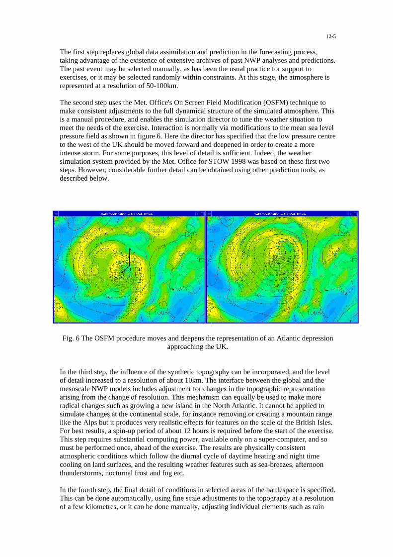
12-5
The first step replaces global data assimilation and prediction in the forecasting process,taking advantage of the existence of extensive archives of past NWP analyses and predictions.The past event may be selected manually, as has been the usual practice for support toexercises, or it may be selected randomly within constraints. At this stage, the atmosphere isrepresented at a resolution of 50-100km.
The second step uses the Met. Office's On Screen Field Modification (OSFM) technique tomake consistent adjustments to the full dynamical structure of the simulated atmosphere. Thisis a manual procedure, and enables the simulation director to tune the weather situation tomeet the needs of the exercise. Interaction is normally via modifications to the mean sea levelpressure field as shown in figure 6. Here the director has specified that the low pressure centreto the west of the UK should be moved forward and deepened in order to create a moreintense storm. For some purposes, this level of detail is sufficient. Indeed, the weathersimulation system provided by the Met. Office for STOW 1998 was based on these first twosteps. However, considerable further detail can be obtained using other prediction tools, asdescribed below.
Fig. 6 The OSFM procedure moves and deepens the representation of an Atlantic depressionapproaching the UK.
In the third step, the influence of the synthetic topography can be incorporated, and the levelof detail increased to a resolution of about 10km. The interface between the global and themesoscale NWP models includes adjustment for changes in the topographic representationarising from the change of resolution. This mechanism can equally be used to make moreradical changes such as growing a new island in the North Atlantic. It cannot be applied tosimulate changes at the continental scale, for instance removing or creating a mountain rangelike the Alps but it produces very realistic effects for features on the scale of the British Isles.For best results, a spin-up period of about 12 hours is required before the start of the exercise.This step requires substantial computing power, available only on a super-computer, and somust be performed once, ahead of the exercise. The results are physically consistentatmospheric conditions which follow the diurnal cycle of daytime heating and night timecooling on land surfaces, and the resulting weather features such as sea-breezes, afternoonthunderstorms, nocturnal frost and fog etc.
In the fourth step, the final detail of conditions in selected areas of the battlespace is specified.This can be done automatically, using fine scale adjustments to the topography at a resolutionof a few kilometres, or it can be done manually, adjusting individual elements such as rain

12-6
rate or visibility to match the exercise requirements. Some of the automated techniques arecurrently implemented in the Met. Office's Nimrod system for very short range forecasting inthe UK, and are being further developed to support battlespace forecasting using CMetS(Computerised Meteorological System). The procedures used in this step are quick andrequire modest computer power, and so could be carried out during the exercise, respondingin real time to the requirements of the exercise director. The output of this step is the finalfour-dimensional description of the atmospheric structure and evolution during the exercise.
The fifth step converts the meteorological conditions into operational parameters. Thisincludes some functions which may be performed on the meteorological system, such ascalculation of illumination levels for NVG or infra-red visibility for target sensing, and othersthat will be performed elsewhere, such as NBC calculations and artillery targetting.
As described earlier, the capabilities described above are all available as by-products of theMet. Office's weather prediction services. In the past, requirements for synthetic environmentsupport have been met by piecing together the relevant components as required. However, inrecognition of the growing importance of this field, the Met. Office is in the process ofestablishing a more permanent capability. Initially, this is taking the form of a demonstratorbased on an updated version of the system provided to STOW. Subsequently it will beexpanded to incorporate the remaining steps in the procedure outlined above.
The procedure described above implies an unrealistic level of certainty in the simulationprocess. This is not a problem if the goal is to create a single scenario for an exercise.However, many of the prediction techniques themselves are capable of generating estimatesof the uncertainty of the result. Increasingly weather prediction is adopting the language ofprobability for its more detailed predictions. While a single decision is needed at the end ofthe process, there are many aspects of military planning for which a risk assessment processincorporating quantitative estimates of weather probability, could be beneficial. Suchprocedures will ultimately need to feed back into exercises and synthetic data creation. Inaddition, since the weather forecast, itself, is part of the exercise, its errors should also beincluded. Errors in manual weather forecasts can easily be simulated using duplicateforecasting teams. For the automated component, more sophisticated techniques are required,using multiple NWP forecast runs, based on small modifications to the initial conditions. Theprocedure outlined above could easily be extended to incorporate this approach.
Other Simulation Requirements for Weather Information
Requirements of simulators are not always best met by creating data in the way describedabove. Indeed, for many purposes requiring conditions only at one point, records of actualweather conditions provide the ideal data source. This is especially true for simulation insupport of equipment design and procurement, and user training, for which information suchas temperature range, maximum wind, occurrence of heavy rain or snow etc is critical. In thisarea, too, new techniques are being applied to enable easier access to the Met. Office'sdatabanks. For access to routine meteorological observations, a PC application is beingprepared for distribution on CD, which will carry a wide range of information, a sample ofwhich is shown in figure 7, in the form currently being tested by the Royal Navy. This versioncarries three-hourly observations of pressure, wind, temperature, humidity, cloud andsignificant weather for land stations, but it is planned to extend it to include marine and upperair data, and to use the synthetic modelling approach to provide information in areas forwhich reliable observations are not available.

12-7
Fig. 7 Example of a climate data presentation for Freetown Airport
For more detailed simulation, application of Met. Office research records may also bevaluable. These have been obtained using the C130 flying laboratory, kite balloons andspecialised surface equipment, for both remote sensing and in situ measurement. An exampleof the level of detail available is shown in figure 8, obtained from the Met. Research Flight C-130. The two plots show temperature and cloud liquid water content data at one-secondintervals through the flight. At the temperatures recorded in this flight, any liquid water couldproduce icing on an appropriate surface.
Fig. 8 Liquid Water Content (LWC), in g of water per kg of air, & temperature in oC recordedby the MRF C-130 aircraft

12-8
Use of such data will require close liaison between simulator designers and meteorologicalscientists, especially as simulators increasingly adopt virtual reality technology.
Summary
The weather has a strong influence on military operations and is likely to become anincreasingly important component of operational decision making as increased weathercapability is built into battle systems.
Based on its operational weather prediction capability, the Met. Office has contributed data tomilitary exercises on many occasions in the past. This capability is currently being assembledinto a PC-based demonstator, which will provide simulated weather information fromcontinental scale down to details of battlespace weather at the kilometre scale.
Detailed information for use in simulators, for training and procurement support, is alsoavailable from Met. Office archives, including routine surface and upper air records, andresearch records from a variety of platforms.

13-1
Dynamic Terrain in the Synthetic Environment
Rita SimonsSimulation, Training and Instrumentation Command (STRICOM)
12350 Research ParkwayOrlando, Florida 32826-3276, USA
ABSTRACT
Simulation has become the primary solution for training U.S. Army soldiers in the use of real weapons systems. Assuch, the requirements for realism and greater fidelity are essential. An area lacking in achieving increased realism isthe representation of Dynamic Terrain (real-time manipulation of the terrain). Command decisions and collectivetraining by maneuver forces rely on terrain cues. The U.S. Army Simulation, Training and Instrumentation Command(STRICOM) has sponsored research in this area since the early 1990s. Early efforts were limited by technology and didnot meet expectations. However, in December 1998 STRICOM awarded a contract to explore and develop an approachfor a low cost, PC based solution for dynamic terrain that has demonstrated strong potential in resolving this long-standing need. A follow-on contract was awarded in December 1999 to implement the approach and demonstrate thefeasibility and effectiveness of the concept. The results of this follow-on contract will be demonstrated at theInterservice/Industry Training Systems and Education Conference (I/ITSEC) in Orlando, Florida from 27-30 Nov 00.This paper describes the phase I and phase II efforts implementation of dynamic terrain into the synthetic environmentusing Distributed Interactive Simulation (DIS) and/or High Level Architecture (HLA) protocols, and a SyntheticEnvironment Data Representation and Interchange Specification (SEDRIS) Transmittal Format (STF) database.
INTRODUCTION
In a distributed simulation environment, the syntheticrepresentation is one of the backbone elements thatprovide for a consistent battlefield. The syntheticenvironment is a representation of the physical world,within which all models of military systems interact. Itincludes both data and models that represent thephysical characteristics of the environment, theireffects on military systems, and the reciprocal impactof military systems on environmental variables (e.g.dust clouds from moving vehicles and spoil fromcombat engineering).
Real-time dynamic terrain has yet to be successfullyrepresented in the synthetic environment. Assimulations have become increasingly sophisticatedand greater reliance on realism necessary in achievingcombat proficiency through training, the presentationof real-time dynamic terrain presents one of the nextchallenges to the community. For the maneuver forceand the combat support elements, the absence ofdynamic terrain presents a significant deficiency intraining objectives. For the maneuver force training ina collective environment, dynamic terrain providescues that have affect on command and control offorces. Soil tracks provide indications of strength anddirection of forces that have previously passed over theterrain. Freshly dug dirt may give an indication ofsome sort of obstacle being placed, such as a mine. Acleared lane through a minefield indicates area of safe
passage. These are all terrain cues that providevaluable combat information. In today’s syntheticenvironment, the capability to represent these cues in areal-time dynamic environment does not exist.Although there have been numerous research efforts,none have provided a reasonable solution that can beused for collective simulation-based training. With thewide assortment of simulators currently fielded in thevarious battle labs and simulation training facilities, aplatform independent software solution for dynamicterrain is a growing need.
BACKGROUND
There have been numerous research effortsinvestigating dynamic terrain. The University ofCentral Florida (UCF), Institute of Simulation andTraining (IST) demonstrated an early prototype ofdynamic terrain utilizing a bulldozer plowing into alake, causing water to flow and surround the bulldozer.The Defense Advanced Research Projects Agency(DARPA) Synthetic Theater of War (STOW) programdeveloped the capability to communicate and emplacechanges in terrain databases. However, results of bothefforts were computationally intensive, requiring high-end computational platforms, and did not sufficientlysatisfy real time requirements.
Paper presented at the RTO NMSG Conference on “The Second NATO Modelling and SimulationConference”, held in Shrivenham, UK, 24-26 October 2000, and published in RTO MP-071.

13-2
THE PC COMPUTATIONAL AND GRAPHICALCAPABILITY
The capability of PCs has increased significantly inrecent years. Tasks that not long ago required high-endproprietary workstations can now be performed on low-cost platforms. A primary reason for the majoradvancements in PC technology can be attributed to thegaming and entertainment community. Because of thepopularity of 3D games, graphics board vendors havebeen adding more and more features in a fiercecompetition where the fastest frame rate and best imagequality wins. These new features include single-passmulti-texturing (which allows for realistic surface detailand lighting), full-screen sub pixel anti-aliasing, andhardware supported transformation and lighting toreduce the burden on the PC’s CPU, giving it moretime to perform other tasks such as artificialintelligence. The result of this competition is that fasthigh-quality graphics can now be generated using low-cost hardware and standard Application Programmer’sInterfaces (APIs).
In military simulation, there is an ever-increasingdemand to support more complexity in the visualizationof synthetic environments. Providing higher fidelitynot only requires faster graphics hardware with newfeatures, but also efficient scene management tools thatcan take advantage of these advancements. The twomain measures of a graphics accelerator’s performanceare polygon count and pixel fill rate. Polygon count isthe number of triangles that can be sent to and renderedby the card in one second. Pixel fill is a measure of thenumber of pixels that can be rendered in one second.When trying to achieve high-speed, high-qualitygraphics, both measures are important. High polygoncount allows for more complex models to be rendered,where pixel fill allows those polygons to be textured,lit, shaded, and anti-aliased. For realistic visualsimulation, a graphics system must be capable of bothhigh polygon count and pixel fill rate. In a dynamicterrain simulation, effects such as dust and visibledifferences in soil type can be used to increase the levelof realism. Effects such as these that were difficult toproduce even on high-end systems not long ago arenow possible with PC technology. Figure 1 illustratesthe level of realism that can be achieved.
Advancements in consumer-level graphics hardwarehave also brought about a more subtle advantage: real-time immediate-mode rendering is now feasible. In thepast, most high-end graphic systems were based onretained-mode rendering. Retained-mode rendering iswhen objects are sent to the graphics system once atinitialization and are stored (retained) there. Thenwhen the object needs to be rendered, it doesn’t have tobe re-sent to the graphics system. This makes mostgraphic operations more efficient but has thedisadvantage of making objects un-modifiable. Thiswas not a problem in the past because there was never a
requirement for a dynamic database. Dynamic terrainby its definition requires the ability to modify the visualdatabase. With the increase in ability of PC-levelgraphic boards, immediate-mode rendering can now beused while still maintaining interactive frame rates.With immediate-mode rendering, objects are not storedin the graphics system, but are re-sent each time theyare rendered. While this does make some operationsless efficient, it allows objects to be modified in real-time from frame to frame. This is what makes dynamicterrain effects possible on a PC. Today, most graphicscards simultaneously support both retained andimmediate mode rendering, so trade-offs can be madeto achieve the desired result.
Figure 1.
According to Moore’s law, CPU complexity andperformance doubles every 18 months to two years.This means that the potential upgrade of hardwarecould have a two-fold performance increase on anexisting application with little or no change in software.With this tremendous advance in chip development, theability to perform real-time, PC based dynamic terrainhas now become a reality. With the heavy competitionin the gaming community, there is no end in sight to thegrowing list of features and performance available inPC graphics cards. For the simulation community, itmeans that by taking advantage of low-cost PCtechnology, features and capabilities previously limitedwill add to the value and realism of training andsimulation systems.
Because of these significant increases in thecomputational performance of PC’s over the recentyears, tasks that previously required high-endproprietary workstations can now be performed on low-cost platforms. Capitalizing on these advances,STRICOM sponsored a Phase I Small BusinessInnovative Research (SBIR) contract to study anapproach for developing a low cost, PC-based terrainsolution. The technical objective required researchingthe feasibility of hosting a realistic, real-time anddistributed dynamic terrain simulation on low cost PCs.A contract was awarded to Diamond Visionics Co.

13-3
(DVC). DVC not only completed a thorough researchof the technical objective, but also demonstrated anearly prototype. Based on the successful outcome ofthe phase I effort, a follow-on phase II contract wasalso awarded to DVC, requiring the completion of aprototype dynamic terrain implementation in an ImageGenerator (IG). The outcome of DVC’s phase Icontract and the objectives of the phase II contract areaddressed in the following sections.
PHASE I - ANALYSIS OF TECHNOLOGY
The technical objective of the phase I effort requiredanalyzing the feasibility of hosting a realistic, real-timeand distributed dynamic terrain simulation on low costPCs. Specific tasks of the phase I effort included:
1) Technical performance requirements analysis in aPC based system
2) Dynamic tessellation3) Soil dynamics trade study4) PC hardware and software architecture5) Dynamic texture6) HLA/DIS prototype study7) SEDRIS Dynamic Terrain Extension Study8) ModSAF Study9) Phase I Option: Dynamic Terrain Technology
Demonstration
Each of the tasks identified above are discussed in thefollowing sections, however dynamic tessellationrepresents the most significant technical challenge inachieving a real-time dynamic terrain environment andis discussed in detail.
Technical Performance Requirements Analysis in aPC Based System. The objective of this task was toanalyze and document, at a high level, the variability ofrequirements from all the possible users of a dynamicterrain implementation. A survey conducted with theuser community resulted in the following conclusions:
1) Special effects such as explosions, spoil, battlefieldclutter and animations were identified as priorityitems.
2) Intervisibility, weather and atmospheric effectswere identified as significant attributes inachieving overall realism.
3) Terrain and soil characterization (for the surfaceand below) was identified as a primary concern.
4) PC IG performance should be a minimum of 30 Hzwith the ability to page in a large terrain database.
The resultant requirements analysis established thefocus for subsequent activities.
Dynamic Tessellation. Dynamic tessellation is theability to deform terrain anywhere in the database inreal-time without the need for predefined deformable
areas. This was the most significant technologicalinnovation identified as necessary in achieving real-time dynamic terrain. In determining the best way toproceed, two primary issues needed to be considered:
1) The ability to break up large polygons in theterrain database in real-time to provide finerdeformation, thus achieving greater realism.
2) The ability to manipulate vertices in the terraindatabase in real-time to achieve terraindeformation.
Three approaches were analyzed as possiblecandidates: 1) Pre-Tessellation which requires theentire terrain database to be pre-tessellated. Thisapproach was not considered feasible due to thesignificant memory requirement; 2) Pre-Tessellation ofselected areas, which limits deformation to selectedhigh interest areas. This approach did not provide therobustness necessary and would require foreknowledgeof interest areas; and 3) Instantaneous Tessellation ofthe entire database. Although instantaneoustessellation of only selected portions of the databasewas investigated as an approach, the ability to preparethe entire database for tessellation was highly desirableto avoid the limitations associated with pre-selectedareas of interest. Although more aggressive, thisapproach was selected due to the greater potentialbenefits.
Instantaneous dynamic tessellation allows a realisticdeformation of terrain caused by interaction with avehicle or other simulated object. Simplistically stated,additional polygons are created in the localized areawhere interaction takes place. This yields a smoothappearance of terrain movement as the vehicle deformsthe terrain. In the initialized database, the terrainconsists of many polygons of various shapes, sides, andsizes (figure 2).
Figure 2.
A boundary area (square box) is established locatedaround the intersection of the vehicle and terrain(figure 3) and this boundary area maintains relativeposition with the moving vehicle.

13-4
Intersection point
Area fortessellation
Figure 3.
All the polygons located within the boundary area arethen triangulated (figure 4) and subsequentlytessellated. This means that each original triangle isdecomposed into four smaller triangles.
Figure 4.
This is done by connecting each segment midpoint tothe midpoint of the other segments in the originaltriangle (figure 5).
Figure 5.
Additional triangles represent a large increase inresolution in the localized area since there are now fourtriangles rendering the terrain area where there used tobe one. Tessellation continues recursively until alltriangles are sufficiently small to achieve the desiredlevel of terrain resolution. Each triangle can betessellated again if necessary for increased resolution.Actual terrain movement is accomplished by alteringvertex positions, so a larger number of triangles willyield a smoother deformation.
However, tessellation poses a problem for the renderingdatabase. New segments created by tessellation are notcorrelated with adjacent un-tessellated polygons.These new intersections are known as T-sections(figure 6).
-T SECTIONS
Figure 6.
Correlation problems need to be resolved or anomaliescaused by small gaps along the edges will occur. Inorder to alleviate this problem, a transient layer iscreated to provide a smooth merging with non-tessellated polygons. First, the triangle with T-sectionsis checked to see if there is more than one T-section. Ifthere is more than one, it is tessellated (figure 7).
Figure 7.
The additional resultant triangles now only contain oneT-section. The one T-section in each triangle is thenconnected to the vertex of the next outer polygon. Thefinal T-sections are then removed by connecting to thevertex of the next outer polygon. This eliminates allthe T-sections and completes the transient layer. Thehigh-density polygons and the low-density polygonshave now been connected seamlessly (figure 8).
Final T-sections
Figure 8.

13-5
T-sections must be tracked in the software. A map isutilized to associate T-sections with the triangles towhich they belong. When a triangle is tessellated, oneach of its sides a center point is generated. The threecenter points are used to construct sub-triangles. Theprogram then maps the center points to their respectivepolygons. If the same point is stored to the map twice,the point will be removed from the map. Aftertessellation, only T-section points are left in the map.Their transient layer generation algorithms describedabove utilize these points.
As the vehicle moves away from the tessellated area,the terrain has been deformed and is no longer beingadjusted. The original area of interest is no longer thecurrent area of interest. If the vehicle stays away for apredetermined amount of time or moves a certaindistance the terrain begins to de-tessellate. During de-tessellation, the extra triangles that were created arenow deleted.
Soil Dynamics Trade Study. Four potential soildynamic approaches were investigated and addressedfrom a feasibility of realism versus cost ofimplementation viewpoint. Actual implementation ofsoil dynamics will be developed in the phase II effort.
1) Physics-based Modeling. Used by IST at UCF.Although rendering an accurate portrayal, thisapproach is not ideal for a PC-based real-timesolution as it is very complicated and extensive,necessitating significant performance overhead.
2) A simplified version of the above approach. Thiscould provide the realism without the high fidelitymodeling to recreate the precise physics of theproblem.
3) Table-derived computational method. Thisapproach would use tables generated from aphysics-based soil model without using extensiverun-time algorithms.
4) Hybrid Approach. A hybrid approach to soilmodeling, which combines tabular data generatedoff line with real time computation.
Soil dynamics was not demonstrated during phase I.Instead, a rudimentary non-validated soil dynamicmodel was used.
PC Hardware and Software Architecture. Thiseffort examined different computing platforms todetermine the best way of solving dynamic terraincomputational issues while maintaining a low costsolution. Factors such as different renderingtechniques, database sizing, and graphic APIs wereconsidered in the analysis. A variety of PC hardwareand software architectures was examined withperformance and flexibility in mind. For the hardwaresolution, high performance at a low cost was the goal.Speed and utility for the software was also a priority.Interestingly, current PC graphics hardware may be
more suitable for dynamic terrain than some very high-end graphics systems. Many high-end systems load thedatabase into very rigid structures in the hardwareitself. This limits access to the database objects,making dynamic modification of terrain and otherobjects very difficult. Most modifications in thesesystems are done using simple replacement of oneobject for another to show changes. This limitationwould make changing individual vertices impossible.PC graphics hardware, however, does not impose theserestrictions. Rendering can be done in “immediatemode.” This means that for each frame, the visualsoftware sends a complete update of the scene to thehardware. The inherent flexibility provided by evengame-level consumer graphics hardware makesimplementing dynamic terrain possible at a relativelylow cost. For the software used in phase I, a set of C++classes was implemented to form a complete databasescene graph modeled closely after the OpenFlightformat. In addition to the scene graph, an OpenFlightloader capable of populating the runtime structure froma standard OpenFlight file was implemented.
Dynamic Texture. This task assessed the feasibility ofdifferent dynamic texture approaches in achievingrealism. Using dynamic texturing methods, manyvisually complex effects can be produced withoutexcessive computational overhead. For this effort, thetexture overlay method was utilized. This methodprovides very realistic effects, while using less memoryfrom the graphic accelerator.
HLA/DIS Prototype Study. The task of developingthe HLA/DIS compatible communication is critical tointegrating with the Army’s networked simulators.Both ModSAF 5.0 and CCTT were studied asrepresentative candidates that would benefit fromdynamic terrain capabilities. Both systems have thecapability to support real-time dynamic terrain objectssimulation. The existing dynamic terrain applicationsare focused on creating effects. The protocol overheadfor transmitting such effects is moderate. Based onthese findings, a conclusion was reached that both DISand HLA can support a dynamic terrain environment.The HLA will be more feasible due to its inheritflexibility. The ModSAF AFI Agile FOM Framework(AFF) provides a good model for futureimplementation. The phase I option contract provideda networked demonstration between multiple dynamicterrain enabled simulators.
SEDRIS Dynamic Terrain Extension Study.Dynamic terrain implementations must comply withSEDRIS, as this is becoming the emerging datainterchange standard. The phase I study concluded thatSEDRIS will readily support the demonstrated dynamicterrain implementation. SEDRIS primarily addressesthe transmission of static synthetic environmentobjects. The evolution of SEDRIS Transmittal Format(STF) and SEDRIS WriteAPI has started addressing

13-6
the object linking, incremental transmission, read-modify-write operation, unique and persistent objectID, and versioning control which all accommodatemodeling and transmitting dynamic syntheticenvironment objects, in both real-time and off-line.
ModSAF Study. The ModSAF terrain functions werestudied in detail and compared with CCTT SAF.ModSAF would support dynamic terrain in the form ofDTSim and DT Agent. ModSAF currently supportsdiscrete changes to the database. The current ModSAFdynamic terrain implementation, using Multi-StateObject, deals with low-level details such as creating,modifying, and deleting polygons and features. Thisscheme will not effectively support the higher fidelitydynamic terrain, based on dynamic tessellation. Bydeveloping dynamic terrain in the ModSAF-compatibleDTSim and DTAgent architecture, but using a moreefficient “behavior-based” control mechanism, it isbelieved that higher fidelity can be supported. IfOneSAF does not change ModSAF’s Dynamic TerrainDTSim and DTAgent architecture, and that OneSAFwill be SEDRIS compatible, the demonstrated dynamicterrain technology can be implemented with OneSAF.
Phase I Option: Dynamic Terrain TechnologyDemonstration. A demonstration was provided at theconclusion of the phase I effort representing theimplementation of the tessellation technologypreviously discussed. The demonstration consisted oftwo dynamic terrain enabled simulators, maintaining anupdate rate of greater than 30 Hz operating on PCs.The instantaneous tessellation techniques and dynamicterrain deformation on the CCTT P1 terrain databasewas also successfully demonstrated.
PHASE II – PROTOTYPE DEVELOPMENT
Understanding that a PC-based real-time dynamicterrain capability was feasible as a result of the phase Iactivities, STRICOM awarded a phase II contract forfurther development of the prototype demonstrated inthe phase I option, extending the capabilities. Thephase II contract development is currently underwayand will conclude in December 2000. Technicalobjectives of the phase II contract are:
1) Requirements Analysis2) Dynamic Tessellation3) Soil Dynamics4) Dynamic Texture5) LOD Management6) Database Paging7) Database Optimization8) Special Effects9) DIS/HLA Protocol Development10) Dynamic Terrain Technology Demonstration
For the phase II effort, the requirement is to prototype areal time (30 Hz) realistic simulation on a selected PCBased IG. In addition, with the wide variety of IGtechnology currently being utilized in Army simulation,the most important objective of the phase II effort isplatform independence. Utilizing Dynamic Terrain(DT) Core, any IG should be able to implementdynamic terrain, with minimum changes required forintegration.
Phase II efforts will integrate instantaneous tessellationwith the soil dynamics subsystem. The soil dynamicsmodule will be developed by the University of Iowaand integrated with the visual networking systems. Thesoil dynamics module requires gridded spatial elevationdata in order to efficiently and accurately simulateterrain interaction. The soil dynamics modulecomputes the deltas in elevation at each post locationbased on the vehicles current action (e.g. digging,sinking, slipping, etc.). The final data set is thensupplied to the tessellation module to determine thebest visual representation for the deformed terrain. Thetessellation module then generates visual levels ofdetail for the newly deformed terrain and applies anytexture modifications required to accurately representthe new terrain state. Dynamic texture methods will beimplemented to achieve realism utilizing the texturedpolygon overlay method. By applying layers to anaffected polygon, the appearance will changedynamically as deformation occurs. For example, asthe blade of a plow cuts into a grassy area, not onlywould the earth be displaced (modifying the underlyinggeometry), but also the appearance of the deformedarea would transition from grass to dirt to make thedeformation more realistic to an observer. Levels ofdetail will be used to reduce the load on the graphicsportion of the system. Physically, when any area isdeformed, the highest level of detail will be modified.Visually, only those areas close to the eye point will berendered using higher levels of detail. Areas furtheraway from the eye point will use lower levels of detailto improve rendering performance. In order tomaintain performance, the dynamic terrain softwarewill need to manage database paging. Paging is a wayof managing memory to maintain performance. Areasof memory that are not currently needed are paged outto the hard drive, thus freeing RAM to be used by othermore critical processes. Conversion of the CCTT P3STF terrain database to an OpenFlight format wasoriginally planned, however due to schedule andbudget constraints, a direct conversion of P3 from theEvans & Sutherland GDF format to the OpenFlightformat will be implemented. The analysis regardingutilizing the SEDRIS STF format is still valid.
A dynamic terrain technology prototype showing thecapabilities and improvements in phase II will be

13-7
presented at the Interservice/Industry Training Systemsand Education Conference (I/ITSEC) in Orlando,Florida from 27-30 Nov 00 in the STRICOM booth.Two exercises incorporating the above objectives willdemonstrate successful implementation of therequirements. These exercises consist of a heavy andwheeled scenario generated by the Maneuver SupportBattle Lab (MSBL), Ft Leonard Wood, MO. Theexercises will show specific instances of dynamicterrain (such as a breach, footprints, explosions,buildup of soil on wheels/tracks, and effects ofsaturated soil on vehicles). The scenarios will beimplemented using both manned simulators andModSAF on a DIS network. As previously stated, theCCTT P3 (Ft Hood) database will be utilized as theterrain database. The architecture utilized for theexercises are outlined in figure 9, with the dynamicterrain implementation identified as Dynamic Terrain(DT) Core.
CONCLUSION
Currently, the synthetic environment lacks a real-timedynamic terrain capability. As the Army migrates to amedium force composition, dynamic terrain capabilityis instrumental to assist in training the combat supportelements and the maneuver forces. With the advancingtechnologies of PC chipsets, a real-time implementationof dynamic terrain is now viable. With these advances,real-time, PC-based dynamic terrain interoperability isnow possible in a distributed simulation environment.With a platform independent software solution,dynamic terrain can be implemented in the manysimulations/simulators being utilized in the Army withminor changes to the software required for integration.As the synthetic environment becomes more robust anddynamic to meet the simulation needs, dynamic terrainis adding to that capability by adding an essentialelement to the maneuver force and the combat supportelements.
Figure 9
Notification Req.
Data U
pdate
Request
Dynamic Terrain Core
Notification
Triangulation
Soil Database Soil Model
SoilModifiers
Blade Track Tire Explosion WreckBall
DISNetwork
IG INTERFACE
Image Generation
Run TimeDB
TextureImages
Render
FootPrint
CCTT P3 TerrainDatabase
TextureMapping
Data
DataLogger
StealthModSAF5.0

13-8
References:
Simons, R., Liu, J., Upton, G., Woodard, T., (2000)Dynamic Terrain in a Distributed SimulationEnvironment with Low Cost PC.
Shiflett, J., (2000) The Exchange of Common SNERepresentations for Distributed SimulationApplications – an Essential Key to Interoperability.
Diamond Visionics LLC. (1999). Low Cost PC-BasedReal-Time Dynamic Terrain, Topic number A98-158,SBIR Report.
Biographical Sketch:
Rita Simons is currently a Visual Systems Engineer atthe U.S. Army Simulation, Training, andInstrumentation Command, in Orlando, Florida.Current responsibilities include investigation oftechnology advances required to enable the use oflower cost PC graphics as the real time imagegeneration for military virtual simulation. She hasearned a Bachelor of Science degree in ElectricalEngineering from the University of Central Florida,and is currently pursuing a Master of Science degree inSimulation.

14-1
Synthetic Environments in AdvancedDistributed Learning
By
M KellySimulation and Training, Land and Weapon Systems,
DERA Chertsey, Surrey KT16 0EE
Phone: +44 (0)1344 63 3388Fax: +44 (0)1344 63 3622
E-mail: [email protected]
and
J AllenSimulation and Training, Land and Weapon Systems,
Phone: +44 (0)1344 63 3586Fax: +44 (0)1344 63 3622
E-mail: [email protected]
Abstract
This paper discusses the potential requirements to link modelling and simulationtechnology to the increasingly important training technology of Advanced DistributedLearning (ADL).
ADL is the fastest growing training technology for intra and internet based trainingapplications and is currently being investigated by DERA for delivering an Army wideUnit Based Training (UBT) capability.
This UBT research programme has highlighted the necessary links and benefits thatmust be made by ADL to the Synthetic Environment (SE) domain. There are anumber of emerging discussion papers defining the requirements for ADL in militarytraining, including a NATO Simulation and Modelling Initiative. These papers allidentify the need to draw from a wide range of modelling and simulationtechnologies.
An application on ADL, Unit Tactical trainer (UTT), has been identified that it willbenefit by employing existing SE technologies. Such technologies include syntheticforces (e.g. MoDSAF). This paper identifies where we can benefit from the advancesbeing made in SE's, allowing an increased utilisation of ADL.
Introduction
Synthetic Environments (SE's) can support all phase of the defence process (Figure1) In a number of these areas the benefits of SE are already being realised. Notably,SE's are already providing a strong underpinning to procurement, via SyntheticEnvironment Based Acquisition (SEBA), Operational Analysis, and Training andMission Rehearsal.
Paper presented at the RTO NMSG Conference on “The Second NATO Modelling and SimulationConference”, held in Shrivenham, UK, 24-26 October 2000, and published in RTO MP-071.

14-2
Figure 1: SE Application Areas in the Defence Process
There are a number of reasons why the SE approach is able to benefit the variousstages of the defence process to such a large degree and they include:
• The reuse of models and data developed for an earlier stage in the process.
• Recording, controlling and manipulating data and modelling assumptions at thedifferent stages.
• Varying model resolution, features and fidelity as the application dictates.
• Providing a controlled and highly visual modelling environments in whichobjective performance measurement can take place.
• Able to utilise models and data developed for different purposes in a commondistributed research environment.
• The adoption of common software standards to maximise reuse and interaction.
Advanced Distance Learning (ADL)
Paralleling the growth in use and popularity of SE's has been the developments inADL using both intra-nets and the inter-nets. Many training programmes that can behosted over a/the web can draw on and link to SE component technologies.Computer Based Training (CBT) systems such as AS90 Training programmedemonstrator designed for the Royal Artillery by Orchard Communications DesignGroup in 1998, draw extensively on SE models.
Figure 2: AS90 Trainer Demonstrator (courtesy Orchard Communications Design Group)
OA Threat assessment Wargames
Systems definition Procurement Design assessment HFI
Training Mission rehearsalWarfare support Digitization
Historical analysis

14-3
The vision for ADL is first to produce a resource for learning that can support localtraining needs (e.g. the military). Then, through the organisation of knowledge intoreusable content, provide a system that through the web would be accessible to allfor training and support activities. Ultimately it is hoped that a web basedorganisation of an encoded, sharable and reusable knowledge base can provide apersonal support system for all human activities (Figure 3).
ADL phase Information content AccessLocal intra and internets Training programmes and
operational supportpackages
Limited access, bespokeapplications, military,industrial and academicorganisations
World Wide Web (II) Sharable organisedknowledge structure tomeet civil and militarytraining needs
World wide access, limitedcontent
Personal Assistant All Human Knowledge Real time wireless access,intelligently organisable, ondemand
Figure 3: The ADL Vision
There are a number of initiatives underway to introduce a wide-ranging infrastructureto support ADL both at the service level, national level and internationally. It is likelythat once the outcome of several policy initiatives (e.g. the Defence Training Review2000) are considered, there will be a move to rationalise the delivery infrastructureacross the services, and produce a tri-service infrastructure and training resource.Nationally there are a number of web-based infrastructures to deliver training to bothindustry and academia.
Internationally there are a number of panels (e.g. Technical Co-operation PanelHum-2, NATO Modelling and Simulation, and NATO ADL Technical Team) that areseeking to ensure an adoption of common standards and international approach tothe introduction and use of ADL. The USA initiative to provide a web based trainingresource that can leverage the civil community is based around the ADL Co Labs(DoD Strategic Plan for ADL,1999).
Unit Based Training (UBT)
One initiative at the service level by the British Army is a programme to develop aninfrastructure for the delivery and management of Distance Learning. The Armyinfrastructure initiative is known as UBT. To support this, the MoD Applied ResearchProgramme (ARP) 07 has constructed an Advanced Technical DemonstratorProgramme (ATDP) in partnership with industry to validate and define the concept forthe UBT infrastructure. The ARTD research programme is primarily designed toaddress three broad areas:
• Unit Training Management, which includes the management of security, shareddata and training records, manpower and maintenance requirements, and costeffectiveness evaluation.
• UBT Technology and Demonstrator, which includes developing the ATDPhardware and infrastructure, developing international links, reviewingunderpinning technologies and understanding the implications of programmes

14-4
that impact on UBT including Digitization of the Battlespace (Land) (DB(L)). Linksto traditional SE's are also being addressed.
• ADL Training Requirements, Processes and Methods, which includes an analysisof the training capability gap UBT will address, and research to prove the trainingeffectiveness of ADL. Research into training methodologies for ADL includereusable and sharable object models for ADL and guidelines for the selection,design, development and evaluation of authoring systems and courseware.
The ATDP will link a Royal Electrical and Mechanical Engineers (REME) package(technical training), a Combined Arms Training School (CATC) package (tacticaltraining), and a Territorial Army (TA) package (unique training needs), to a DERAresearch hub with links to international sites including the US ADL Co-Lab (Figure 4).
CATC
TA
REME
UBT
DERAHUB
Figure 4: UBT ARTD Programme Concept
Applications on UBT
The UBT infrastructure is being designed to be able to deliver a wide range oftraining benefits and operational support packages for the British Army. In UBT, abroad concept of units is adopted including: Phase 1 initial recruit training throughPhase 2 and 3 training at both the Army Training and Recruitment Agency (ATRA)and Arms Schools, to the unit level itself. It also includes training progression fromindividual through team and special to arm, to Collective Performance (CP) levels 1-3within a combined arms environment. These training benefits and operationalsupport packages include:
• The pre-collective skills (British Army CP levels 1-3) that underpin collectivetraining.
• Individual and team component military skills.
• Skills underpinning the use of tools supporting the DB(L), such as GP3 (digitisedoperational command and control system) and QP24 (digitised logistics control),which in recent Army trials have been identified as being subject to acute skillfade.
• A wide range of military technical and educational courses, existing and new.

14-5
• Courses for career development, such as Vocational and Non-VocationalQualifications (NVQ), etc.
• Training to meet the new demands for Operations Other Than War (OOTW) orPeace Support Operations (PSO).
• Provide a training audit trail.
• Provide unit level links to the US Unit Training programmes.
• Provide training in-theatre.
• Provide training on route to theatres (e.g. onboard ship).
• Provide training at home, for both NVQ and TA support.
• Provide asynchronous training, ‘training anywhere any time’.
• A host environment suitable for the proposed Unit Tactical Trainer (UTT) system.
Currently both a web-based and an intranet solution are being pursued. The weboffers wide access but lowered security, though it is believed adequate for the levelsof training anticipated. The intranet offers additional security, possible enhancedbandwidth (at a cost) but an associated low access. The feasibility of a combinedsystem with firewalls between the Army WAN and the web has also been explored.
Unit Tactical Trainer (UTT)
The 1996 (UTT) Statement of User Requirements stated that, ‘there is no effectivetraining system that provides doctrine and tactical training for commanders within aunit. It is proposed that this capability gap should be addressed by a system knownas UTT.' It is anticipated that by 2003/4 UTT will provide a Commercial Off The Shelf(COTS) training solution for tactical training through an LAN of PCs or as anapplication eventually hosted on the UBT infrastructure (Figure 5). UTT will provideall arms, collective, tactical training and skills maintenance at both the combat andcombat support unit and sub-unit levels.
Figure 5: Unit Tactical Trainer Concept
UBT?
Classroomserver
LAN
AutomatedAAR facility
CPGroup
2 PlComd
1 PlComd
A CoyComd
3 PlComd
WAN
TrainingManagement
Simulation(e.g. ModSAF)

14-6
The UTT concept test-bed has been developed utilising Modular Semi-AutomatedForces (ModSAF) version 5.0 and the US Training Exercise Development System(TREDS) version 3.2 (Crissey, et al 1994). The concepts test-bed also highlightedthe need to use objective training metrics and for them to be supported by an Army-wide training management system. Low trainer manning and the need for automatedAfter Action Review (AAR) such as the Exercise Analysis for Collective Training(EXACT) system (Kelly, et al 1996) was also identified.
The emergence of training systems such as UTT, using SE components such asModSAF, databases and exercise management systems, including AAR systems,which can be delivered over the web (e.g. internet compatible version of Janus -Brigade Combat Team) indicate the need for the SE community to be aware of webdevelopments. These two scientific communities are now starting to come togetherand there needs and applications are beginning to overlap.
Common Standards
The standards that underpin the successful use of SE's, such as DistributedInteractive Simulation (DIS), High Level Architecture (HLA), ADL, SyntheticEnvironment Data Representation Interchange Specification (SEDRIS), etc., arematched in the web domain by emerging standards for packaging, referencing andretrieving objects.
The US DoD has established the ADL initiative to develop a strategy for usinglearning and information technologies to modernise military education and training.This initiative has defined high-level requirements for learning content such asreusability, accessibility, durability and interoperability. As a result of this, there hasbeen an attempt made to specify a reference model that abstracts runtimeconstraints and defines a common interface and data scheme for reusable content -this is known as the Sharable Courseware Object Reference Model (SCORM).SCORM has now entered a test and evaluation phase, during which corrections,clarifications and improvements will be gathered. The eventual goal of SCORM is toallow individually tailored training to be delivered 'anytime, anywhere, to anyone thatneeds it.'
A reference model is needed to aid the successful implementation of the ADLinitiative, which will require the issue of guidelines that are shared and observed byorganisations that have a stake in the development and use of instructionaltechnology materials. These guidelines may be of an international or nationalstandard, agreed upon practices, recommendations, or de facto practices. If they areto be successfully articulated and implemented, they must be based on a common'reference model.' Such a model will not actually replace the detailed models ofinstructional system design or practices that have been devised and adapted byspecific organisations. Its purpose is to describe an approach to developinginstructional material in sufficient detail to permit guidelines for the production ofsharable courseware objects to be clearly articulated and implemented. There arethree primary criteria for SCORM:
• Fully support articulation of guidelines that can be implemented for the productionof sharable courseware objects.
• It must be adapted and used as much as possible by a wide variety ofstakeholders.
• It must permit mapping of any stakeholders’ specific model for instructionalsystem design and development into itself.

14-7
It is estimated that investment costs could be reduced by 50-80% through the use ofthis model. These sharable courseware objects should be:
• Durable - does not require modification as versions of system software change.
• Interoperable - operates across a wide variety of hardware, operating systemsand web browsers.
• Accessible - can be indexed and found as needed.
• Reusable - can be modified and used by many different development tools.
At its basic level, SCORM defines a web-based learning 'content model.' It can beseen as a set of interrelated specifications designed to meet the DoD's high levelrequirements for web-based learning content reusability, accessibility, durability andinteroperability. In its current iteration, SCORM comprises three major elements:
• Course structure format - an Extensible Mark-up Language (XML) basedrepresentation of a course structure.
• Runtime environment - a definition that includes a specific launch protocol toinitiate executable web-based content.
• Metadata (i.e. data about data) - a mapping and recommended usage of Instituteof Electrical and Electronics Engineers (IEEE) LTSC Metadata elements (i.e.course, content and raw media Metadata).
Benefits of the Web for SE
Ensuring SE's are able to adopt these emerging standards will produce two majorbenefits. Firstly, that a part of the ADL community who that can utilise SE modelsand databases will be readily able to access them. Secondly, the web will provide anexcellent data repository for the SE community. The benefits of a web-baseddatabase and model repository includes:
• Access to models for the SE community.
• An organising resource for SEBA.
• Reuse of SE models and data in ADL applications.
• Data organised for access, retrieval and use.
• Recording key facts (data sources, assumptions) origins of models, originalpurposes, updates and configuration control.
A number of initiatives as are under way to explore this option (e.g. Euclid 11:13).
Security
There are a number of barriers to the wide implementation of military models anddata in and Internet environment. In particular, a number of practical issues doemerge in the consideration of security in utilising the web but many of these arecultural barriers and not technical. Barriers to the introduction of the Internet for SEand ADL applications can currently be seen to include:
• Identifying and challenging organisational 'Gate keepers.'
• Fears over job or role losses and threats to power (both expert and positional).

14-8
• Potentially unnecessary security requirements for selected Military data.
• Organisational culture (blame, secrecy and bureaucratic issues).
• Change overload in the training domain.
• Change to training support from learning.
• Hidden benefits in the 'status quo' systems.
• Problems of data ownership, authoring and data control.
Conclusions
This paper has briefly highlighted the need for the two communities of ADL and SE'sto remain aware of the developments and trends in their respective domains and tobe aware that their paths are due to cross. Early recognition of the emergence ofnew standards in the ADL community and their vision for the future will benefit thefurther expansion and wider adoption of SE's.
Bibliography
1. Crissey, M., Stone, G., Briggs, D. and Mollaghasemi, M. Training ExercisePlanning: Leveraging Technologies and Data. I/ITSEC ConferenceProceedings and Presentation, December 1994; also TREDS DATA TOOLS,www.stricom.army.mil/PRODUCTS/TREDS, 1994.
2. Dodds, P. (Ed), Shareable Courseware Object Reference Model (SCORM),Version 1.0, Advanced Distributed Learning, 31 January 2000.
3. D/DGD&D. Unit Based Training (UBT), Statement of User Requirement.D/DGD&D /4/81/18/1, 21 Oct 1999.
4. Department of Defence Strategic Plan for Advanced Distributed Learning,ODUSD(R), Readiness and training, Apr 1999.
5. Janus (Brigade Combat Team) web game internet reference:www.shrapnelgames.com
6. Kelly, M., Caudrey, J. and Marsh, R. AAR: Performance Measures and theEXACT Training Analysis System. DERA/CHS/HS3/CR96095, 1996.
7. MoD Policy Paper, DGD&D(R&T)6/6/1/1, May 1999.
8. Patrick, J., Training Research and Practise, Academic Press, London, 1992.
9. Training Systems Technology Unit Tactical Trainer Training Needs AnalysisFinal Report. P39118, 1998.

15-1
The Use of Virtual Simulation for DismountedInfantry Training
Mr. J. D. Smith, Mr. J. SteelRoyal Military College of Science, Cranfield University
Shrivenham, SN6 8LA, UK
Abstract:
This paper discusses the use of Virtual Simulation and Synthetic Environments (SEs) for the training of thedismounted infantry (DI) soldier. The paper covers the needs and issues for this training and gives a seriesof examples of active research applications including improvements in terrain fidelity.The approaches for current Infantry training are outlined together with a broader review of other armstraining. The development of virtual simulations/SEs as training media in all areas of military training isdiscussed. The limited examples of virtual simulation for DI is discussed, including the representation of DIin other simulations (eg the UK Combined Arms Tactical Trainer (CATT)).Current thinking on the important characteristics for virtual simulation for DI training is outlinedincluding the user interface, terrain, graphics, weapon simulation, networking, CGF and infrastructure.Within this the difficulties of providing adequate and useful infantry training simulations are highlighted.Examples addressing the above are detailed. These include a desktop Infantry representation simulator foruse in large scale networked simulations (eg CATT). Research directed at improving the terrain fidelity forinfantry simulations is also be covered in detail.Finally the strands for future work are outlined briefly including work on the required characteristics ofVirtual Environments for effective training applications.
Introduction
This paper outlines the issues surrounding the use of virtual simulation for the training of dismountedinfantrymen. A major research thrust has been underway at Cranfield University Royal Military College ofScience to assess the potential requirements for training using virtual environments and to evaluatealternatives against some of these requirements. This paper discusses the issues, outlines some of thecompleted research and identifies the current and planned future activities.
The term virtual simulation is used to describe simulation with which a user interacts by using an interfacethat is intended to represent a soldier’s equipment and portray the view and other features of the real worldwhich he would encounter. Thus the user is immersed to some degree, in an environment which representsthe real one. In comparison, live simulation is that where users are in a real environment using realequipment whose effects are simulated (an example here is a TESEX laser/MILES-based exercise).Constructive simulation is that where equipment is simulated and the system operators are simulated –human /user interaction may be an element but is limited to direction of units or broad control oftactics/movement and this does not involve using simulated controls representing the real systems.
Paper presented at the RTO NMSG Conference on “The Second NATO Modelling and SimulationConference”, held in Shrivenham, UK, 24-26 October 2000, and published in RTO MP-071.

15-2
Current Uses of Simulation for Army Training
Simulation of all types is in widespread use for army training worldwide and is increasing. Constructiveand virtual simulations have advantages over other forms of training, for example they permit higherfidelity/realism than classroom training and are, of course, cheaper than field training.Other benefits include
• reduced damage to the environment,• ease of exercise design and construction,• repeatability of conditions,• analysis and after action review or replay and• controllability of timing and flexibility.
This is especially true for simulations employed for commander training where the commander and hisstaff can be trained whilst his forces are represented within a simulation.
Examples of current or imminent virtual simulations include tank part- and full-task training simulators, theMILAN missile simulator, helicopter simulators and networks of virtual simulations in training systemssuch as Combined Arms Tactical Trainer (CATT) in the UK or the Close Combat Tactical Trainer (CCTT)in the US.However the use of virtual simulation for infantry training is limited. The UK has the Small Arms Trainer(SAT) and the LAW simulator which train in the operation and limited use of these weapon systems. Bothrequire a significant amount of specialist equipment and are limited to single or few participants.
In the US there have been more developments in the use of simulations of all varieties. There are similarweapons trainers to the UK and in addition considerable strides have been taken in evaluating simulationfor other aspects. The Dismounted Warrior Network has been developed as a testbed applied to the 21st
Century Land Warrior programme and for differing training options. In addition the US has deployedsystems based on commercial games and is currently configuring Delta Force 2 for use as a small unittraining tool.
One other aspect is worthy of note. As well as the use of simulation for training of infantrymen therepresentation of infantry in simulations aimed at training other arms has some deficiencies. There is aparticular concern that systems such as CATT may not represent the infantry sufficiently realistically forthe tank and AFV crews to develop adequate familiarization with tactics and procedures when engaging oroperating with infantry.
Challenges for Infantry Simulation
The reasons for the slower adoption of simulation for infantry training in the UK and in the US are thedifficulties associated with implementing appropriate systems.
These systems would vary according to the application but, for illustrative purposes, let us use a potentialsystem where a soldier would don a Virtual Reality helmet of some sort and control a weapon. He wouldmove through a simulated environment (displayed in his vision device) and detect and engage enemy forceswho would also engage him. These enemy could be other VE equipment users acting against him or,alternatively, computer generated and controlled forces. He would also act with other members of his force,who would also be either other users of VE equipment networked with him or computer generated forces.
Some of the challenges in delivering this type of solution are as follows:
The User InterfaceA tank interior can be mocked up and a crewman sees the outside world largely through sensors that can bereadily simulated with computer displays, similarly helicopters etc. For a soldier the view needs torepresent the real-world view from an individual in the outside world. Thus to be realistic a high fidelity 3d

15-3
view surrounding the man needs to be generated and updated. This is potentially expensive and requireshigh fidelity databases, high fidelity displays, either a headset as described above or possibly projectionsystems surrounding the user. To drive this requires appropriately powerful processing systems. Theinfantryman’s weapon ideally needs to be in his hands and needs to be operated in a realistic mannerrequiring tracking and other interfaces.
CostFor a simulation system to be deployed in useful numbers for infantry training it must be sufficientlyinexpensive. The UK will have a limited number of CATT facilities (2 initially) each capable ofBattlegroup level training. A similarly small number of infantry training facilities might well be unusablegiven the number of infantry units and the wide training needs. For some intensive applications such anumber of expensive highly capable systems might be appropriate. For other simpler training applicationsthere would be the need for more accessible solutions. One method might be distributed systems, forexample an expensive facility accessed remotely from other locations.
NeedField training is still needed and always will be, particularly for infantry. Some training elements, eventhough amenable to using VE might not be required in anything other than as real field exercises because ofthe other elements that this brings.
Terrain DatabasesOne of the major problems of using virtual simulation for the training of dismounted infantry is the terraindatabase. These databases have been generated for other training purposes such as for vehicle simulators.This often means that the resolution of the terrain representation is relatively low. For an infantryman onthe ground every bush, dip, valley, channel and mound is important, as they offer places of concealment.
NetworkingThe transmission of sufficient data defining his state, stance and activity in a understandable format usableby the other entities and components within a distributed simulation network provides a challenge. Thesupport provided for articulation of limbs etc within the DIS protocol, for example, is very limited. Thismeans that the portrayal of an infantryman simulator from other linked simulators would be unrealistic inappearance and actions.
CGFOne alternative for the soldier simulator system above is for all participants to be based on mannedsimulators. This clearly results in cost and effort implications each time an exercise is run. The betterapproach is to use computer generated enemy and also computer generated friendly forces if possible. Thecurrent state of the technology for providing either of these is limited. The simulations which provideinfantry CGF lack adequate behaviours in many aspects and are frequently found to be unrealistic. Toaccurately represent infantry behaviour requires a substantive representation of infantry tactics and humanbehaviour.
SummaryNow it may be that these views are extreme. Research activity is geared to identifying the level of fidelitywhich might be required in these areas for differing applications, for example it may not be necessary for afull, high fidelity VR headset view for some applications, perhaps for a small unit leaders’ proceduraltraining simulation. It may be that a desktop interface is adequate and teaches enough of the principleswithout the need for greater immersion. As another example, it may be that simple CGF is adequate forsmall arms firing training. However for most applications all these points have some, albeit varying,validity.

15-4
Project Research Examples
RMCS have completed a number of research projects directed at these challenges.These include
• an evaluation of the requirements to develop a basic networked Virtual Reality system for DI,• the development of a demonstrator representing a DI within a networked VR system,• the investigation and demonstration of a low cost interactive networked DI training system based
on commercial products and• the demonstration and trials of a desktop DI Trainer.
The following section of the paper outlines a selection of other activities which are either completed orongoing.
High Detail Terrain DatabasesThis activity investigated the feasibility of increasing terrain complexity by adding desirable and detailedfeatures to an existing, sparsely cultured database.
Initial stages of this work were to make use of one of our original terrain databases. We wanted to be ableto modify the terrain surface in some way, to add in the real terrain features of such importance to infantry,such as dips and mounds. The terrain databases available at RMCS are all polygon mesh based. Thus, toincrease the terrain resolution, we need increase the polygon count for the mesh.
To illustrate the process, we can consider a single polygon within the surface mesh as shown in wire framein Figure 1(a). The polygon represents an area of 128m x 128m which is typical of the polygon size in arepresentative terrain database representing Fort Hunter Liggett. The first stage of the process is to sub-divide the original polygon into a sub-mesh as shown in Figure 1(b). In the figure, the original polygon hasbeen divided into 512 sub-polygons. To this new mesh, a noise filter can be applied, allowing the verticesof the mesh to be perturbed. The filter can be controlled in increase the amplitude and frequency of theperturbations. Figure 1(c) shows the result, with Figure 1(d) showing the solid filled image.
Figure 1: Addition of Terrain Complexity
(c) (d )
(a) (b )

15-5
Figure 2 shows the view of the new terrain surface from a viewpoint approximately 2m above the surface.It can be seen that the added terrain relief increases the feature richness of the surface adding in therequired dips and mounds.
Figure 2: Final Result
Although, there is spare processing capability, if we were to apply the technique to every polygon in ourterrain model, the system is likely to run at rate where it is difficult to interact with it. The current databasecontains approximately 80,000 triangles over a region of 30km x 10km, so this could increase by twoorders of magnitude. However, for an individual infantryman, the terrain only in the immediate area needbe at the higher level of detail. The aim is to implement a level of detail mechanism whereby as theinfantryman moves over the terrain surface the terrain model is replaced with one of higher detail.However, since the switching between levels will occur at relatively short distances, the effect will be verynoticeable. To overcome this, the technique of using a progressive mesh may be the solution. Here thedetail in a model changes dynamically as the viewpoint moves.
One of the major problems in using this process is due to one of the classic inter-operability issues wherebythe terrain model is not the same. This leads to unfair fight conditions, whereby one system believes he ishidden, but another clearly sees him. In addition, the technique does not add any terrain features such asroads, rivers, trees or buildings. In fact, if these objects already exist then the modification of the terrainsurface will cause these objects to become miss-placed.
Flight Deck OfficerCurrently the British Royal Navy Flight Deck Officers (FDO) are trained at RNAS Culdrose, Cornwall,England. Although their training is shore-based, they make extensive use of real simulation, learning todirect real helicopters onto a landing area. If, however, the weather conditions restrict aircraft flights oraircraft are unavailable, then the training makes use of a virtual simulator.Research at the RMCS is looking into improving this virtual simulator. The current system requires thevirtual helicopter to be flown by an individual, who is typically the class instructor. The pilot flies thehelicopter, responding to the signals given by the trainee. The research at the college is looking intomethods whereby, using suitable tracking devices, computer software interprets the arm movements of thetrainee and the corresponding signal determined. This is then fed into the dynamics model of the helicopter,thus alleviating the instructor from needing to actual fly the craft. Such a system would allow for more thanone trainee to be trained at a time and would allow all of the benefits of computer-based training to beapplied. Figure 3 shows a still-image from the research system.

15-6
Figure 3: Flight Deck Officer Virtual Environment
It is hoped that this work will be applicable to the training of dismounted infantry, in that the sametechniques developed for the identification of the arm signals of the FDO could be used for those of aninfantry commander.
CATT InfantryThis project completed by Maj. Hutchinson was designed to develop better representation of dismountedinfantry not for infantry training per se but rather to improve the representation within simulation systemssuch as CATT. The project constructed a new plug-in dynamics model for the CrewStation2000 vehiclesimulator. Figure 4 shows the crewstation in operation.
Figure 4: CrewStation in Operation
The dynamics model simulates an individual infantryman, giving the ability of the user to move over theterrain surface, change his stance and to aim and fire a weapon as shown in Figure 5.

15-7
Figure 5: Dismounted Infantryman
Figure 6 shows the view as seen through the gun sight when the operator is aiming his weapon.
Figure 6: Dismounted Infantryman Gun Sight
This project overcame significant technical challenges and has provided a working and more representativeDI simulator which is used at RMCS for participation within distributed simulations. The simulator still

15-8
requires one human operator to control one DI. However, the project also laid the foundations for furtherwork to develop a system which would allow a single controller to operate and command severaldismounted infantrymen as a way of improving DI representation within distributed simulations in a moreefficient manner.
Future Plans
Cranfield University at RMCS are continuing the research thrust in several concurrent strands.Two initiatives have been commenced in late summer, the first to examine distance estimation in VEs incomparison to the real world and the other into the feasibility and adequacy of transfer of navigation skillsdeveloped through training in VE.
The plan for other research is as follows. To review infantry training including the exercise structure, theordering of training and the details of the skills required to be developed with each training element and tocross compare these against the capabilities for VE to train in these types of tasks.From these activities a shortlist of those infantry tasks that appear most amenable to some sort of VE willbe identified. These will then be further filtered by evaluating whether there would be benefit (especially incost and safety aspects) from being performed with a VE.
This process will act as the direction for further research and is intended to formulate several other researchactivities to build prototype VE systems and conduct trials with these in varying configurations to ascertainwhether they will support the training, whether the skills learned in VE transfers to the real world.
Conclusions
There are significant challenges in applying simulation to the training of dismounted infantry. Muchresearch is required to improve the capability of technology to meet these challenges and to betterunderstand the appropriate form and characteristics of the types of systems which might fulfil the trainingrequirements in the most effective and cost efficient way.Cranfield University has completed a number of research activities directed at this area and is activelycontinuing this work.

15-9
Key References/Sources
Sastry, V. S. S., Trott, E.A. and Steel, J., “A Virtual Environment for Naval Flight Deck OperationsTraining”, NATO Human Factors and Medicine Panel Workshop, The Hague, The Netherlands, April2000.
Steel, J., “CrewStation2000 – User’s & Developer’s Guide”, AMOR 2000/6, Cranfield University, 2000.
Stanney, K.,Mourant, R.,Kennedy,R., ‘Human Factors Issues in Virtual Environments’, Presence Vol 7 No4, 1998
Knerr,B., Lampton,D., Singer, M., Witmer,R., Goldberg,S., ‘Virtual Environments for Dismounted SoldierTraining and Performance: Results, Recommendations and Issues’, US Army Research Institute Nov 1998
Jacobs,R., Crook,W., Crooks,J., Colburn,E., Fraser,R., ‘Training Dismounted Soldiers in VirtualEnvironments: Task and Research Requirements’, US Army Research Institute Oct 1994
Pleban,R., Eakin,D., Salter,M., ‘Analysis of Mission-Based Scenarios for Training Soldiers and Small UnitLeaders in Virtual Environments’, US Army Research Institute Jan 2000
Hall, C., Stiles,R., Horwitz, C., ‘Virtual Reality for Training: Evaluating Knowledge Retention’, IEEE1998
Darken, R., Banker,W., ‘Navigating in Virtual Environments: A Virtual Environment Training TransferStudy’, IEEE 1998
O’Byrne,J., ‘Human Interaction within a Virtual Environment for Shipboard Training’, Naval PostgraduateSchool, Monterey, Ca, Sept 1995
Ford, P., Andre, C., ‘Evaluation of Dismounted Infantry Simulation Technologies’, US Army ResearchInstitute
Nemire, K., ’Immersive Virtual Environments for Dismounted Infantry Tactics Training and MissionRehearsal’, Interface Technologies Corp
Brent, Maj P., ’Networked Virtual Reality for Dismounted Infantry,’ RMCS Jul 1998
Ourston, D., Reece,D., ‘Issues Involved with Integrating Live and Artificial Virtual IndividualCombatants’, SAIC Stricom
Hutchinson, Maj. N., ‘The Simulation of Dismounted Infantry’, RMCS, 2000
Clarkson, Maj M., ’Low Cost, 3D, Interactive Networked Training’ RMCS 1998
Jones, Maj. I., ’Desktop Dismounted Infantry Trainer A Proof of Concept Demonstrator’, RMCS 1999

This page has been deliberately left blank
Page intentionnellement blanche

17-1
Aircrew Mission Training Via Distributed Simulation – A NATO Study
B N TomlinsonFMC Dept
Defence Evaluation & Research AgencyRoom 36 – Bldg 109
Bedford MK 41 6AE, UK
1 Background
This paper is about the future potential in NATO of Aircrew Mission Training viaDistributed Simulation, or MTDS. A Military Applications Study (known as SAS-013) on MTDS has just concluded, having been sponsored by the NATO Research &Technology Organisation (RTO)1, through its Studies, Analysis and Simulation (SAS)Panel. The study report will be published shortly. The task of the study was
“To assess the potential of advanced distributed simulation to complement liveflying training in order to enhance NATO capability to conduct combined airoperations.”
This could be re-phrased as “How can NATO apply recent improvements indistributed simulation technology to enhance current and future NATO training for airoperations?” Note that, according to NATO definitions (source: NATO AAP-6),Combined Operations are defined as operations between two or more forces oragencies of two or more allies. Joint is defined as activities, operations, organisations,etc., in which elements of more than one service of the same nation participate.
This paper will discuss some of the results of the SAS-013 study and will describeplans for further work.
The SAS-013 study has been conducted by a multi-national Study Team, led by theUK, consisting of serving Air Force personnel and national experts in simulationtechnology and aircrew training from Belgium, France, Germany, Italy, TheNetherlands, Turkey, UK, and the USA. Team members also included representativesfrom the aircraft and the simulation industries.
2 What is distributed simulation?
Distributed simulation can mean many things to many people. In the present context,advanced distributed simulation is about enabling a collection of compatible advancedflight simulators to be linked together via modern networking technology in order tocreate a shared virtual “battlespace” in which all components can participate toconduct operational training and mission rehearsal tasks. In the context of the NATOstudy, this concept has been given the label “MTDS” - Mission Training viaDistributed Simulation - in order to distinguish it from various national initiatives,such as the US DMT (Distributed Mission Training) programme.
© British Crown copyright 2000. Published with the permission of the Defence Evaluation and Research Agency
on behalf of the Controller of HMSOThis paper represents the views of the author and should not be taken to represent MOD or RAF policy
Paper presented at the RTO NMSG Conference on “The Second NATO Modelling and SimulationConference”, held in Shrivenham, UK, 24-26 October 2000, and published in RTO MP-071.

17-2
Figure 1 illustrates the concept, in which examples of flight simulators from severalnations are linked together in a common simulated battlespace, which can also includecommand and control elements such as AWACS. In the illustration, a TacticalControl Centre1 is also shown from which a training exercise is controlled andmanaged.
F-15(USA)
Tornado GR4 (UK)
Rafale (FR)
F-16(BE/DK/NL/NO/TU)AWACS (NATO)
Eurofighter(GE/IT/SP/UK)
Threats ISTAR
Future Systems
Courtesy CAE
Figure 1 Vision of distributed mission training
3 Statement of the Problem
There is growing interest in NATO in the potential use of advanced distributedsimulation for team and collective mission training for military aircrew. Live flyingtraining is becoming increasingly limited due to a combination of factors, includinglack of airspace availability, environmental and security constraints, concern aboutconsumption of aircraft flying hours and airframe life, the cost of major exercises andlimited opportunities to practise co-ordination of critical multi-national NATO airmissions in a representative operational environment, complete with threats. Peace-time constraints typically preclude full operational use of Electronic Warfare (EW)systems, defensive aids such as chaff and flares and firing of live weapons. Data linksare also extending the “tactical reach” of an air package. Thus, training methods haveto adapt.
Combined forces from a number of member nations typically conduct NATO militaryoperations. The collective nature of these operations means that members of the
1 Illustration of UK Medium Support Helicopter Aircrew Training Facility courtesy of CAE
Electronics Ltd.
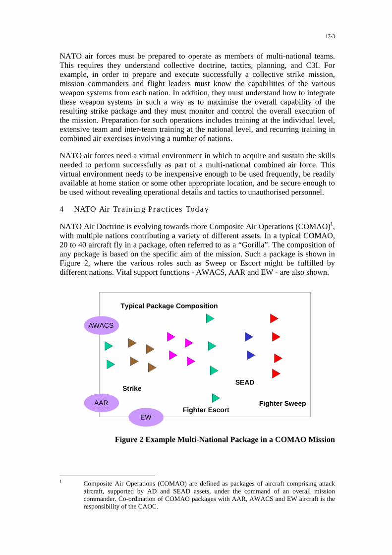
17-3
NATO air forces must be prepared to operate as members of multi-national teams.This requires they understand collective doctrine, tactics, planning, and C3I. Forexample, in order to prepare and execute successfully a collective strike mission,mission commanders and flight leaders must know the capabilities of the variousweapon systems from each nation. In addition, they must understand how to integratethese weapon systems in such a way as to maximise the overall capability of theresulting strike package and they must monitor and control the overall execution ofthe mission. Preparation for such operations includes training at the individual level,extensive team and inter-team training at the national level, and recurring training incombined air exercises involving a number of nations.
NATO air forces need a virtual environment in which to acquire and sustain the skillsneeded to perform successfully as part of a multi-national combined air force. Thisvirtual environment needs to be inexpensive enough to be used frequently, be readilyavailable at home station or some other appropriate location, and be secure enough tobe used without revealing operational details and tactics to unauthorised personnel.
4 NATO Air Training Practices Today
NATO Air Doctrine is evolving towards more Composite Air Operations (COMAO)1,with multiple nations contributing a variety of different assets. In a typical COMAO,20 to 40 aircraft fly in a package, often referred to as a “Gorilla”. The composition ofany package is based on the specific aim of the mission. Such a package is shown inFigure 2, where the various roles such as Sweep or Escort might be fulfilled bydifferent nations. Vital support functions - AWACS, AAR and EW - are also shown.
Fighter Sweep
SEAD
Fighter Escort
Strike
Typical Package Composition
AWACS
AAR
EW
Figure 2 Example Multi-National Package in a COMAO Mission
1 Composite Air Operations (COMAO) are defined as packages of aircraft comprising attack
aircraft, supported by AD and SEAD assets, under the command of an overall missioncommander. Co-ordination of COMAO packages with AAR, AWACS and EW aircraft is theresponsibility of the CAOC.

17-4
Opportunities to prepare for COMAO-style operations are limited. NATO hasestablished the “Tactical Leadership Programme”, better known as the TLP, with abase in Belgium. The aim of this programme is to foster tactical leadership in largepackages. During flying courses, experienced aircrews (2-ship or 4-ship leaders) learnto plan and to execute complex missions as leaders of a 30-aircraft package, typicallyincluding air-to-air, air-to-ground, reconnaissance, SEAD, EW, AAR and AWACSassets. Usually, these exercises take place partially in uncontrolled airspace. TLP iswidely acknowledged as providing some most valuable opportunities for NATOcollective air tactical training. NATO air training practices today also include theannual “NATO Air Meet” (NAM) exercise, where participating nations may send 4 or8 of their best aircrews to fly COMAO and to discuss tactics with the other NATOaircrews. Major national exercises, such as the US “Red Flag” series, also providevaluable training opportunities.
5 Training needs
As part of the SAS-013 study, a typical scenario and mission, or “reference mission”,have been defined and then analysed to identify the skills and competencies requiredby the aircrews involved, and hence the training requirements. The reference missionis embedded in the scenario and together they have also served to define the keyelements of a distributed training environment to meet the mission trainingrequirement.
It was assumed in the SAS-013 study that aircrew members participating in missiontraining for combined air operations possess the basic individual and team skillsneeded to be categorised as “combat ready”.
For such aircrew to be effective as members of a multi-national force, they must trainto operate as part of a collective involving two or more teams from two or morecountries. In order to meet this training requirement, aircrew must master the skillsnecessary to employ their individual weapons systems effectively in accordance withnational and NATO standards. In addition, they must also master a number of teamskills involving communication, co-ordination, planning, decision making, andsituation assessment that will be exercised in a complex multinational operationalenvironment.
An exercise based on MTDS offers the opportunity for national and multi-nationaltraining of aircrew to:
� Refine individual and collective skills in complex, interactive, and uncertainmission environments that are difficult or impossible to duplicate in peace-timetraining;
� Develop the flight lead and mission commander skills that are necessary tosuccessfully plan, execute, and assess combined air operations.
Advanced distributed simulations provide an effective means to train reasoning skills,meta-cognitive skills, risk-assessment skills, and communication skills without theoverhead and complexities of real-world training. In addition, simulations can becontrolled and repeated to ensure that aircrews receive the structured experiencesneeded to develop specific skills. Scenario events can be carefully crafted to providespecific stimulus-response opportunities that are tied to the training objectives. This

17-5
means that opportunities to develop or exercise specific skills are directly tied toscenario events so that mastery can be assessed. This linking of training objectivesand scenario events helps to ensure that valuable training time is focused on essentialskills.
6 The state of the art in distributed simulation technology
The study has reviewed the state-of-the-art in advanced distributed simulation andfuture trends. It has done this in two ways, by looking at the technology itself and alsoby documenting national initiatives and experience relevant to Mission Training viaDistributed Simulation.
Simulation technology has advanced substantially in the past 5 years, especially invisual display quality, representation of the operational environment, and computergenerated forces. A modern advanced simulator can provide a virtual battlespace withany real-world geography and including photo-realistic imagery, provided the dataand imagery are made available. It is possible to create a realistic threat environment,where threats fire back. Costs have also fallen, so that multi-ship configurations forcollective training and COMAO are becoming affordable. While furtherimprovements are still needed distributed simulation systems can be put together andare usable today.
As part of its work, the study has identified national initiatives in distributedsimulation. A variety of demonstrations and experiments have been conducted,including
� Multi-Distributed Training Testbed, MDT2 (US) 1996 (Taylor, 1996)� TRACE - Transatlantic Research in Air Combat Engagement (US/GE)� EUCLID RTP 11.3 demonstration of a Complex Air Warfare Training System,
1997, (GE, NL, TU, UK)� Joint Project Optic Windmill (NL)� STOW97 (US/UK) Nov 1997 (Budge, 1998 and Hobden, 1998)� Air Defence Synthetic Environment (UK) Feb 1998 (Gale and Pugh, 1998)� Roadrunner 98 (US) Nov 1998� Trial Ebb & Flow (UK) Feb 2000 (McIntyre et al, 2000)� ULT-JOIND (Unit Level Trainer - Joint Operations Integrated Network
Demonstrator), (NL) 2000
Experience gained through these initiatives (eg Gentner, 1999; George, 1999) at suchresearch facilities as the US Air Force Research Laboratory, at the DefenceEvaluation and Research Agency in the UK and at the TNO in the Netherlands showthat there is hard evidence of the feasibility and utility of distributed simulation. It isnot just a dream. There is still a lot to do, however, to make such activities usable on aregular basis.
Procurements of a new generation of advanced aircrew training systems, with thepotential to be part of a distributed simulation mission training exercise, are also inprogress in many nations. These include
� In the USA, the USAF Distributed Mission Training (DMT) Programme forAir Combat Command, with F-15C 4-ship simulators installed at Eglin and
17-6
Langley AFBs in 1999, the first step in achieving a vision of a “Joint SyntheticBattlespace” by 2010.
� In the UK, a new generation of fast jet mission simulators for the Tornado GR4(RAF), and Eurofighter (RAF) and, for the helicopter force, the WAH64Apache Longbow (Army) mission simulators and the Medium SupportHelicopter (RAF) simulators. All of these training systems have the potential tobe linked to a wide area network.
� In Canada, plans for the CF-18 Advanced Distributed Combat TrainingSystem, part of an Advanced Distributed Mission Simulation concept.
� In France, the Combat Training Centre (CTC) at Mont de Marsan.� Germany, Italy, Spain also have plans for Eurofighter simulators.� Netherlands (with Norway and Denmark), F-16 MLU Unit Level Training
Devices.
Simulators for MTDS have to meet certain requirements. Not only must they benetwork-capable, employing standard message protocols such as DIS or HLA, theyalso need to ensure common representation of the operational environment(geophysical, weather and tactical) and interoperability in terms of compatible systemmodels and behaviours. Some guidance is given in the study report.
7 Technical and training challenges
Many technical and training challenges have to be met in order to establish MTDS asan effective method for advanced aircrew mission training. These include
� Infrastructure - suitable networks to be available� Common data - shared : environment, threats etc� Data Security - policy and technical
Simulation technology is steadily becoming increasingly capable, but there are stillcritical technology areas, including:
� Improved visual systems, especially display technology� Better representation of the operational environment (day, night, all weather)
and methods to exchange common databases� More realistic behaviours in Computer Generated Forces� Compatibility and Interoperability - much more than just networking – issues
include correlation between visual/sensor databases and interactions betweenentities
� Standards e.g. in networking and in database interchange� Creation and management of an affordable and usable network infrastructure� Methods and tools to support the whole Exercise Management life cycle� Multi Level Security
8 Principal findings
The study has found that
� Mission Training via Distributed Simulation (MTDS) offers promise ofsubstantially enhancing NATO’s operational effectiveness in COMAOs andother air operations, and is viable now.
� It is increasingly recognised that, in isolation, live flying training cannotprepare NATO aircrew for future composite air operations (COMAO) – thereis a “training gap”.

17-7
� Mission Training via Distributed Simulation (MTDS) can begin to fill the“training gap”, by overcoming some of the limiting factors in live flyingtraining, particularly
� representation of the operational environment� complex ROEs, C3I and restrictions on full use of EW, defensive aids
and weapons� cost of flying training (Exercises, attrition, aircraft life)� availability of aircrew, airframes and airspace, including ranges� safety, environmental and security concerns
The study also notes that MTDS and live flying are complementary, and that MTDSwould offer opportunities to extend the scope of training to include the chain ofcommand.
MTDS has potential to
� Provide multi-national training opportunities in large force employment� Include high-value assets (AWACS) in simulation� Practise co-ordination, procedures, tactics� Explore “what if’s” - more effective operations� More focused use of flying training time� Involve wider air operations community - CAOC, Intel� Mission rehearsal
MTDS can also provide the means to assess future systems and concepts, to developand try out doctrine and tactics, to assess proposed force capabilities prior toparticipation in operations, and to support simulation based acquisition. Indeed,nations willing to participate in NATO air operations could well be expected to joinan MTDS exercise first.
9 How should NATO proceed?
The study recommends that
� NATO should recognise that mission training via distributed simulation hasgreat potential to complement live flying training in order to enhance NATOcapability to conduct combined air operations.
� NATO should declare its intent to exploit modern distributed simulation toimprove its capability in air operations.
� NATO and the Nations should pursue the exploitation of Mission Training viaDistributed Simulation.
It will, however, take some years to establish MTDS in NATO. Both national andNATO initiatives are required. For example, nations need to acquire suitable nationalsimulation assets (the study report offers guidance on the required technicalcapability). The first relevant national systems (e.g. in the US DMT program) weredelivered in 1999 and are evolving in other nations. There is also a need for researchand demonstrations, both nationally and in NATO.
Among the recommendations of the SAS-013 study are some proposals for furtherwork. These include the formation of a Concept Development and DemonstrationTask Group (SAS-034). While the study has said the concept of MTDS “is a goodidea”, it has conducted no actual trials or exercises. Some real experience is now

17-8
needed before NATO can bring MTDS into regular use. Thus, the aim of the SAS-034task group is to spread awareness of MTDS throughout the NATO militarycommunity and the nations, and to conduct a preliminary multi-nationaldemonstration of the potential in NATO of aircrew mission training throughdistributed simulation. This will be undertaken in collaboration with the MSG-001task group of the NATO Modelling & Simulation Group.
The SAS-034 Task Group, which will begin work in Spring 2001 and last for 3 years,is currently being formed, and its Terms of Reference and programme of work arebeing defined. The Task Group team currently includes participation from Canada,France, Germany, Italy, The Netherlands, UK, and the USA. Further participationfrom the operational community in nations and in NATO is being sought, as well asfrom other panels of the RTO.
It is also planned to hold a NATO Symposium in 2001 on the theme “MissionTraining via Distributed Simulation in NATO - Achieving and maintaining cost-effective readiness in the 21st Century”.
10 Concluding remarks
Preparation for effective conduct of air operations in NATO and exploitation of smartweapons will be founded in future on mission training via distributed simulation.
Some follow-on initiatives are now required, and are being planned, to develop theconcept and to enable distributed simulation to be used as an effective trainingmethod in the NATO air community. These activities include a need for experimentsand exercises
� to learn more about how to achieve real training value from MTDS incollective air operations
� to acquire further experience in applying the technology
Nations are already starting down the road towards acquiring simulation assets thatwill be the building blocks in NATO MTDS.
Now is the time to take action on technical requirements and standards to avoid futureinteroperability problems – we do not need to wait until all problems are solved. Co-ordinated research is required in nations, particularly in the areas of collective trainingfor air operations, distributed simulation technology and interoperability.
An evolutionary programme needs to start now to deliver NATO MTDS capabilityvia Concept Demonstration, followed by an implementation plan leading ultimately tofull exploitation.
Acknowledgements
The author wishes to acknowledge the valuable contributions of all the SAS-013 teammembers to the work of the study. The content of this paper, however, is theresponsibility of the author.
The author also wishes to acknowledge financial support for the study from UK MoDDefence Research Package 25c and from the International Research Collaborationprogramme.

17-9
Glossary of abbreviations
AAR Air-Air RefuellingADSE Air Defence Synthetic EnvironmentAFB Air Force BaseAWACS Airborne Warning and Control SystemCAOC Combined Air Operations CentreCOMAO Composite Air OperationsCTC Combat Training CentreDIS Distributed Interactive SimulationDMT Distributed Mission TrainingEUCLID European Co-operation for the Long Term in DefenceEW Electronic WarfareHLA High Level ArchitectureMLU Mid-Life UpdateMTDS Mission Training via Distributed SimulationNAM NATO Air MeetNATO North Atlantic Treaty OrganisationNMSG NATO Modelling and Simulation GroupROE Rules of EngagementRTO Research & Technology OrganisationRTP Research and Technology ProjectSAS Studies, Analysis and Simulation (Panel)SEAD Suppression of Enemy Air DefenceSTOW Synthetic Theater of WarTLP Tactical Leadership ProgrammeTNO Applied Research Laboratory, the NetherlandsULT-JOIND Unit Level Trainer - Joint Operations Integrated Network
Demonstrator
References
Budge L et al, 1998. 'Synthetic Theater of War (STOW) 97 Overview', Spring 98Simulation Interoperability Workshop, Orlando, paper 98S-SIW-086, March 1998
Gale S L and Pugh Major G, 1998. ‘The Air Defence Synthetic Environment (ADSE)Demonstration – Deriving the Benefits’, paper 2, Conference on “Networking inSimulation and Training – Realising the Benefits”, Royal Aeronautical Society,London, 11-12 November 1998
Gentner F C et al. ‘Using Mission Essential MOEs/MOPs for Evaluating Effectivenessof Distributed Mission Training’, paper presented at Interservice/Industry TrainingSimulation and Education Conference (I/ITSEC), Orlando Florida, Dec 1999
George G R et al. ‘Air Force C2 Training Solutions in Distributed Mission TrainingEnvironments, a Report From the Synthetic Battlespace’, paper presented atInterservice/Industry Training Simulation and Education Conference (I/ITSEC),Orlando Florida, Dec 1999

17-10
Hobden D et al, 1998. 'United Kingdom in STOW 97 - lessons learned', Spring 98Simulation Interoperability Workshop, Orlando, paper 98S-SIW-113, March 1998
McIntyre H M et al, 2000. ‘Improving Operational Effectiveness: A Vision forAircrew Mission Training’, paper presented to The Royal Aeronautical Society, FlightSimulation Group Conference on “Flight Simulation – The Next Decade”, London,10-11 May 2000
Smith M E and McIntyre H M. ‘Mission Training Through Distributed Simulation’,paper presented to conference on “Air Crew Training 2000 Plus”, Brussels, 10-11June 1999
Taylor H L et al 1996. ‘Evaluation of the performance and cost-effectiveness of themulti-service distributed training testbed (MDT2)’, paper 15, Conference on “Theprogress and direction of distributed interactive simulations”, Royal AeronauticalSociety, London, November 1996
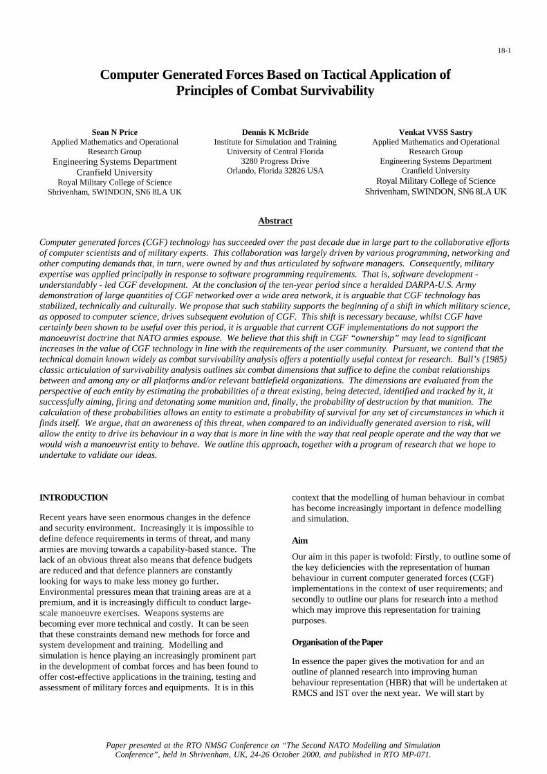
18-1
Computer Generated Forces Based on Tactical Application ofPrinciples of Combat Survivability
Sean N PriceApplied Mathematics and Operational
Research GroupEngineering Systems Department
Cranfield UniversityRoyal Military College of Science
Shrivenham, SWINDON, SN6 8LA UK
Dennis K McBrideInstitute for Simulation and Training
University of Central Florida3280 Progress Drive
Orlando, Florida 32826 USA
Venkat VVSS SastryApplied Mathematics and Operational
Research GroupEngineering Systems Department
Cranfield UniversityRoyal Military College of Science
Shrivenham, SWINDON, SN6 8LA UK
Abstract
Computer generated forces (CGF) technology has succeeded over the past decade due in large part to the collaborative effortsof computer scientists and of military experts. This collaboration was largely driven by various programming, networking andother computing demands that, in turn, were owned by and thus articulated by software managers. Consequently, militaryexpertise was applied principally in response to software programming requirements. That is, software development -understandably - led CGF development. At the conclusion of the ten-year period since a heralded DARPA-U.S. Armydemonstration of large quantities of CGF networked over a wide area network, it is arguable that CGF technology hasstabilized, technically and culturally. We propose that such stability supports the beginning of a shift in which military science,as opposed to computer science, drives subsequent evolution of CGF. This shift is necessary because, whilst CGF havecertainly been shown to be useful over this period, it is arguable that current CGF implementations do not support themanoeuvrist doctrine that NATO armies espouse. We believe that this shift in CGF “ownership” may lead to significantincreases in the value of CGF technology in line with the requirements of the user community. Pursuant, we contend that thetechnical domain known widely as combat survivability analysis offers a potentially useful context for research. Ball’s (1985)classic articulation of survivability analysis outlines six combat dimensions that suffice to define the combat relationshipsbetween and among any or all platforms and/or relevant battlefield organizations. The dimensions are evaluated from theperspective of each entity by estimating the probabilities of a threat existing, being detected, identified and tracked by it, itsuccessfully aiming, firing and detonating some munition and, finally, the probability of destruction by that munition. Thecalculation of these probabilities allows an entity to estimate a probability of survival for any set of circumstances in which itfinds itself. We argue, that an awareness of this threat, when compared to an individually generated aversion to risk, willallow the entity to drive its behaviour in a way that is more in line with the way that real people operate and the way that wewould wish a manoeuvrist entity to behave. We outline this approach, together with a program of research that we hope toundertake to validate our ideas.
INTRODUCTION
Recent years have seen enormous changes in the defenceand security environment. Increasingly it is impossible todefine defence requirements in terms of threat, and manyarmies are moving towards a capability-based stance. Thelack of an obvious threat also means that defence budgetsare reduced and that defence planners are constantlylooking for ways to make less money go further.Environmental pressures mean that training areas are at apremium, and it is increasingly difficult to conduct large-scale manoeuvre exercises. Weapons systems arebecoming ever more technical and costly. It can be seenthat these constraints demand new methods for force andsystem development and training. Modelling andsimulation is hence playing an increasingly prominent partin the development of combat forces and has been found tooffer cost-effective applications in the training, testing andassessment of military forces and equipments. It is in this
context that the modelling of human behaviour in combathas become increasingly important in defence modellingand simulation.
Aim
Our aim in this paper is twofold: Firstly, to outline some ofthe key deficiencies with the representation of humanbehaviour in current computer generated forces (CGF)implementations in the context of user requirements; andsecondly to outline our plans for research into a methodwhich may improve this representation for trainingpurposes.
Organisation of the Paper
In essence the paper gives the motivation for and anoutline of planned research into improving humanbehaviour representation (HBR) that will be undertaken atRMCS and IST over the next year. We will start by
Paper presented at the RTO NMSG Conference on “The Second NATO Modelling and SimulationConference”, held in Shrivenham, UK, 24-26 October 2000, and published in RTO MP-071.

18-2
reminding ourselves of the requirements of the usercommunity. NATO armies now espouse a manoeuvristapproach to the conduct of operations, and we will brieflyoutline this philosophy. We will then consider the maincurrent implementations of CGF and identify weaknesseswith them in the light of these requirements. Following abrief description of ModSAF, including the mechanism forthe generation of behaviours, we will introduce theconcepts of Combat Survivability Analysis1. We will usethese concepts to suggest a mechanism whereby CGFentities within a simulation can reach a perception of thethreat that they face - in a way that real combatants might– and take action depending on each individual entity’saversion to risk. We suggest that this addition willintroduce an unpredictability in entity behaviour which isnot currently present and is representative of realcombatants rather than being purely random. Further, wecontend that this unpredictability will allow the generationof more realistic-behaving entities for use in trainingsimulations.
MANOEUVRE WARFARE
War is a human activity. The human element is central to thecauses of war, its conduct and its resolution. NapoleonBonaparte2 famously stated that “in war, the moral is to thephysical as three is to one”. To develop Napoleon’s commentfurther, any discussion of combat that considers only physicalfactors, neglecting the human ones, is, at best, a 25% solution.
Current British military doctrine3 emphasises the central roleof Manoeuvre Warfare Theory on the conduct of operations.This doctrine envisages a successful battle or war being foughtthrough the prosecution of a judicious combination of attritionand manoeuvre. In this sense attrition means the destruction ofmen, forces and materiel and manoeuvre means movementand action aimed at denying the enemy freedom of action andrendering any action he does take irrelevant. Utilised on itsown, either approach is flawed. In particular, attrition on itsown is unlikely to be successful unless the General that seeksto attrite has a great advantage in combat power. Even this isfar from a guarantee of success. Research suggests thatnumerical advantage is amongst the worst predictor of combatoutcomes4.
1 Ball, “The Fundamentals of Aircraft Combat Survivabilityand Design”.
2 In a letter to his brother, then Governor of Spain, 27 August1808. Quoted in Tsouras, “Warriors Words”.
3 Directorate General of Development and Doctrine, "ADPOperations".
4 Hughes, "Two Effects of Firepower", quoting researchconducted by Robert Helmbold.
Manoeuvre warfare seeks to create the psychologicalconditions for defeat in the mind of the enemy. As such itthrives on fear and uncertainty in battle. Attrition will play apart in this process, but, as Clausewitz said, “military activityis never directed against material force alone: it is alwaysaimed simultaneously at the moral forces which give it life,and the two cannot be separated5” As Grossman has stated,“the essence of manoeuvre warfare (is) that you defeat theenemy’s will to fight rather than his ability to fight6. TheGerman “blitzkrieg”, which proved so successful in the earlyyears of the Second World War, furnishes an example of therelationship between attrition and manoeuvre. Thedistinguishing feature of the blitzkrieg offensive was theavoidance of battle7 through the utilisation of suppression.This tactic rendered the defenders actions irrelevant andensured that they were constantly reacting to changingcircumstances. The blitzkrieg thus drove events, leading to therapid collapse of the defender’s will to continue. As Hugheshas said “no attrition model can explain the blitzkriegphenomenon, which was achieved by an intensive, localsuppression of the defender’s ability to resist8.
It can thus be seen how manoeuvre warfare seeks to attainvictory through the mind of the enemy, rooting out hiscritical vulnerabilities and exploiting them. This is thecontext in which trainers wish to train and analysts wish toconduct their analysis. The implicit thesis of this paper isthat the current generation of modelling and simulationtools do not sufficiently support this process. We wouldconcur with Pew and Mavor, who state that, at present, itappears that "users of military simulations do not considerthe current generation of HBRs to be reflective of thescope or realism required for the range of applications ofinterest to the military".9
PROBLEMS WITH CURRENT CGFIMPLEMENTATIONS
What CGF are and why current implementations are notgood enough
CGF are "computer representations of vehicles andhumans for use in simulations"10. They represent a simpleand cost-effective way of populating a synthetic
5 Clausewitz, “On War”, 157.
6 Grossman, "Defeating the Enemy's Will", 142.
7 Simpkin, “Race to the Swift”, 34.
8 Hughes, "Two Effects of Firepower".
9 Pew, “Modeling Human and Organisational Behavior”, 19.
10 Pew, “Modeling Human and Organisational Behavior”, 38.

18-3
environment11 (SE) with entities. CGF entities may beused to provide an enemy force or flanking or supportingfriendly forces. A single operator can control manycomputer-generated entities, reducing the manpower billfor the conduct of simulations. Thus a typical SE willconsist of entities controlled by humans (mannedsimulators) working alongside or against entities generatedby computer. Together, these entities will occupy acommon synthetic world, allowing interaction betweenthem.
An ideal CGF can be seen as being the integration ofphysical models (weapon systems, sensor suites, etc.) withcontrolling behavioural aspects (command, control,communication, situational awareness and the other lesstangible human factors such as physical degradation, fear,leadership and morale, to name but a few). The physicalmodels represent the state and activity of the militaryhardware within the simulation. Models such as this havebeen the subject of much work in the past, and it appearsto be fair to say that they are reasonably well understood12.The controlling behavioural aspects of the simulationdetermine how the entity behaves in a given set ofcircumstances. The aspiration, at least, is that human-controlled entities within the simulation cannot distinguishcomputer-generated entities from other human-controlledentities. Unfortunately, general consensus would appear tobe that we are still some way off achieving this level ofcredibility. Pew and Mavor, writing in the most recent anddefinitive source on HBR for combat models andsimulations, state that "it is fair to say that, in terms ofmodels in active use, the introduction of human behaviorinto military simulations is in its infancy. However,because of the wide range of potential uses of these kindsof models, it is badly needed to create more realistic anduseful evaluations"13. Further, it would appear that suchmodels do not have the confidence of the user community.In a book likely to be on the reading list for a student atStaff College in the UK or the USA, Robert Leonhard, aserving US Army officer, states that "the main problemwith computer modelling is that it is incapable ofsimulating the true essence of war. Computers are perfectfor investigating ballistic equations, the durability ofarmor, and the lethality and radius of munitions. But thestate of computer simulation in the US Army does notallow for proper evaluation of fear, morale, indecision,deception and exhaustion, although history teaches us thatthese factors and other intangibles are the crucialdeterminants of a conflict. In short, computer-generated
11 Where a synthetic environment is defined as “a synthesisedrepresentation of a common world which permits interactionbetween players”. Definition courtesy of the SyntheticEnvironments Co-ordination Office (SECO), MOD.
12 Ritter, “Techniques for modelling human performance inSynthetic Environments”.
13 Pew, “Modeling Human and Organisational Behavior”, 44.
armies lack critical vulnerabilities”14. Whilst the state ofHBR was of a significantly lesser standard when this workwas written than it is now, the authors would contend thatthe thrust of Leonhard’s point is still very much true - thatcurrent implementations of CGF generally fail to meet theuser requirement. CGF thus need to be improved in linewith user requirements if they are to continue to beconsidered useful
CGF users and their requirements
Simulations and synthetic environments are used acrossthe defence spectrum. Pew and Mavor identify threeprimary classes of simulation user; those that usesimulations to train individuals or teams; those that usethem to conduct analyses designed to inform developmentof doctrine and systems or support procurement decisionsor contingency plans; and those that are concerned withimproving command and control and interoperability. Inessence we can simplify these down into two key areas:simulation for training and simulation to support analysisand decision making. These two broad communities havevery different requirements for their models andsimulations. The training community requires models thatexhibit credible and variable behaviour, related to thetrainee with an appropriate degree of fidelity in real time.The analytical community is interested in the process andoutcome of simulation runs, requiring repeatability andclear statements of assumptions and conclusions, verypossibly in greater-than real time15. Figure 1 summarisesthe key requirements of HBR for each of the user groups.
Requirements of HBR for key user groups
The TrainingCommunity
The Analysis Community
Req
uire
men
ts
BELIEVABILTY
VARIABILITY
VALIDITY OFACTION ASPERCEIVED BY THETRAINEE
OBJECTIVITY
REPEATABILITY
VALIDITY OF ACTIONAS PERCEIVED BY THEANALYST
Figure 1
It is important to note the issues of perspective raised, andtheir relevance for the modelling of decision making. Forthe trainer/trainee, entity behaviour should appear to berealistic from his perspective. Given that he will not beaware (with any degree of certainty) of the mission that theentity is conducting, it’s particular situational awareness ora myriad of other factors that may affect it, this judgementcan only be arrived at in broad terms. In essence, it is
14 Leonhard, “The Art of Maneuver”, 141.
15 Synthesised from p.13, Pew, “Modeling Human andOrganisational Behavior”.
18-4
impossible for the observer to validate the actions of theentity without placing them in the context of the entity’sknowledge. However, the analyst using such simulationsis going to need to satisfy himself that the entity’sbehaviour is consistent with its beliefs about the world. Inother words, he must validate behaviour from theperspective of the entity. This is a much strongercondition. Petty16, in looking at the suitability of a Turing-type test for CGF, concluded that assessments of validityof behaviour were not relevant for the training communityin the light of the primary goal – the production of trainingbenefit. However he concluded that such a test was ofgreat importance for analysts, who had to have a great dealof confidence that entity behaviour was valid.
Key to our understanding of what will constitute a usefulmodel is the purpose to which it will be put. In essence,we need to consider the defence context against whichHBR must be viewed. In a recent supplementary review toPew and Mavor, Ritter et al17 state that "the usercommunity for synthetic forces would be better served ifall these uses were supported by a single system orapproach”. We would suggest that, whilst this may be alaudable aspiration in principle, it is unlikely to berealisable in practice in the near future18. As identifiedabove, each of these areas will have different modellingand simulation requirements, hence placing differentrequirements on the representation of the human. It issurprising that there is, in essence, one effort to develop auseful general simulation of human behaviour rather than aseries of efforts related to each of the requirement areas.Pew and Mavor acknowledge that "given the current stateof model development and computer technology, it is notpossible to create a single integrative model orarchitecture that can meet all the potential simulationneeds of the services". In other words, different users needdifferent CGF. This should be no great surprise; we wouldnot try to use a model for some purpose that it is notappropriate or was not designed for in any other problemdomain. Pew and Mavor go on to state that "the modelermust establish explicitly the purpose(s) for which a modelis being developed and apply discipline to enhance modelfidelity only to support those purposes"19. The authorswould hence consider it an essential precursor to anymodel development to establish the specific needs of theproblem domain. Further, we would consider it unlikelythat a single model would have a span of applicability thattranscends the problem domains identified above. Wewould therefore contend that distinct modelling efforts are
16 Petty, "The Turing Test as an Evaluation Criterion forComputer Generated Forces".
17 Ritter, “Techniques for modelling human performance insynthetic environments”.
18 As indeed Ritter et al go on to point out.
19 Pew, “Modeling Human and Organisational Behavior”, 2, 5.
required to develop suitable CGF models for each of thetwo key domains of training and analysis. In the former,the measure of success will be believable, credible entitybehaviour as judged by the trainee from his perspective asan observer. In the latter, it will be judged on therepeatability and objectivity that the analyst can use toconstruct well-designed and meaningful experiments toinform studies and on the basis of credible and valid entitybehaviour as judged by the analyst from the perspective ofthe entity.
Much of the research effort into HBR and CGFdevelopment over the past 10 years appears to have beendedicated to finding deliberative architectures that lead torational decisions in a traditional knowledge engineeringsense. This approach is sanctioned by Pew and Mavorwho state that, "(I)deally, individuals will exhibit behaviorthat reflects rational analysis and evaluation of alternativecourses of action, including evaluation of alternativeenemy actions, given the context"20.
However, whilst this may be a laudable aim for theanalysis community, we suggest that low level combat isnot a rational process. At the lower levels of combat,soldiers and vehicles rely greatly on practiced actions anddrills in order to allay the inevitable confusion of battle.Decisions typical of this level have been termed ActionFirst Decisions21. To a certain extent these do not qualifyas decisions at all, in that they are more instinctive actions,or perhaps “compiled” actions, to borrow from expertsystems terminology. They are a consequence of training,common sense or some other stimulus. In essence they aredesigned to ensure that the individual in some dangerousor threatening situation does not have to think what to donext. Further, individuals will reach different conclusionsabout the state of the battle based on their experience,situational- and environmental-awareness. This will inturn lead to the generation of different actions that mayseem rational to the individual but are probably less so toan observer. Given that, in a training scenario the traineeis the observer, it is arguably impossible for the trainee tovalidate the behaviour of the entity. Our approach hencedoes not attempt to introduce independently validatablebehaviors, but believable ones. It is hence a lesserrequirement attempting to introduce an element ofunpredictability into decision making that is currently notpresent in ModSAF.
In line with the above, this paper will concentrate on howCGF can better serve the training community. Trainingwas the sphere in which CGF were first utilised and it is inthis area that applications have undoubtedly had thegreatest success so far. Hence we will concentrate on therequirements of trainees in real-time virtual simulations,
20 Pew, “Modeling Human and Organisational Behavior”, 13.
21 Basan, "A Framework for a Unified Decision MakingProcess".

18-5
almost certainly networked and distributed. In line withPew and Mavor, we see the goal for CGF improvement inthis domain to be that "participants in real-time distributedinteractive simulations will see the performance ofindividual soldiers and higher-level units in terms of theindividual and unit behavior they exhibit, the execution ofplans they formulate, and the battle outcomes that result.Although explanations of how the behavior comes aboutmay be useful for after-action reviews, they are not neededduring simulation execution. Only the outcomes need tomeet the expectations of the audiences that will observethem. Similarly, detailed rationales for how groupsaccomplish tasks are generally irrelevant. What isimportant is that the group behavior mirrors that which isexpected in the real world"22. In other words, we wish toimprove the believability of CGF in accordance with theexpectations of the trainer and trainee.
ModSAF – The state of the art in CGF generation tools
There are several computer programs that are designed toallow the generation of CGF. The most widely used, andthe basis for several planned packages23, is Modular Semi-Autonomous Forces (ModSAF). ModSAF is “a set ofsoftware modules and applications that constructDistributed Interactive Simulation (DIS) and ComputerGenerated Forces (CGF) applications entities used forrealistic training, test, and evaluation on the virtualbattlefield. ModSAF contains entities that are sufficientlyrealistic resulting in the ‘illusion’ that the displayedvehicles are being maneuvered by human crews, ratherthan computers”24. It was designed as a research testbedfor the development of CGF implementations for actualSE systems such as CTTT and the planned British versionCATT. It is currently distributed to the authors as Version5, and continues to be developed under the auspices andguidance of STRICOM. A full description of ModSAFcan be found in the Functional Description Document25
and the ModSAF Software Architecture Design andOverview Document (SADOD)26, but a brief overviewwill be given here to place our planned work in context.
ModSAF claims to be able to “replicate(s) outwardbehavior of units and their component vehicle and weaponsystems to a level of realism sufficient for training andcombat development”. Further, it goes on to claim that“(T)he kinematics and dynamics of its vehicles cannot be
22 Pew, “Modeling Human and Organisational Behavior”, 12.
23 OneSAF, for example, is based on ModSAF.
24 Science Applications International Corporation andLockheed Martin Information Systems, "ModSAF 5", 1
25 Science Applications International Corporation andLockheed Martin Information Systems, "ModSAF 5".
26Lockheed Martin, “Software Architecture Design andOverview Document”.
distinguished by persons in manned simulators from thoseexpected in manned simulators. The tactical behavior ofall semi-automated units is designed to be doctrinallycorrect with defaults drawn from unclassified sources.”27.Whilst the implementation meets its claims at one level ofabstraction (the physical aspect of ModSAF entitiesmirrors that of manned entities in an SE exactly), it iswidely accepted that ModSAF entities are less accuratelyrepresented in most behavioural aspects. For example,ModSAF entities do not have the appreciation of groundthat leads to sensible and credible route selection. Theyneed to be told exactly how to move in order to appearcredible to the observer.
ModSAF consists of a set of software libraries and toolsthat allow the physical creation of entities within somevirtual environment. The program is accessed through auser-friendly graphical user interface (GUI) which allowsthe rapid creation of entities and their tasking. There are awide variety of types of entity that can be created in allcombat domains. Further, users can define new entitytypes with relative ease (although ModSAF is a verycomplex system that does require considerable effort tobecome familiar with). Each entity type can be created asenemy or friendly forces. Further, entities bring with thema basic doctrine describing how the entity will react incertain circumstances along with other information such asstandard ammunition carriage and weapon engagementranges. Entities can be created individually or asorganisations. In the latter case a command structure iscreated along with the entity that allows orders to be givento units and distributed to entity level.
Having created entities, the ModSAF user can then assignbehaviours to them to meet the requirement of the SE thatthey are being used to populate. This is achieved throughthe generation and combination of entity tasks, againthrough a graphical user interface. Tasks govern theautomated behaviour performed by a ModSAF entity orunit. For an individual entity such as a vehicle, exampletasks might be vehicle move, avoid collisions with otherentities, search for enemy vehicles, etc. In the case of aformed unit, such as a platoon, tasks might be unitmovement or attack an objective, for example. Thesetasks can then be composed into task frames that definehigher level activities. Task frames consist of a set ofrelated tasks that run concurrently. An example might bemoving whilst looking for enemy and being aware of whatto do in case of contact - such a task frame might define abasic entity advance to contact. Task frames can then becombined sequentially to produce missions. Hence,ModSAF behaviours, observed through tasks, task framesand missions, are composed of relatively simplebehavioural building blocks. These individual tasks areimplemented within the program as finite state machines(FSM). Figure 2 relates tasks, task frames and missions asfound in ModSAF.
27 Lockheed Martin, “Software Architecture Design andOverview Document”.

18-6
Figure 2
A FSM is a theoretical computer science construct that canbe understood as follows. At any moment in time themachine will be in certain state. An input to the machinemay cause it to change to a new state. The machine iscalled finite state because there are only a finite number ofstates that it can be in. In this context, then, we view atask (FSM) being conducted by a ModSAF entity as beingin a certain state at a certain time (for example abackground task to search for enemy). An input that isrelevant (such as the detection of an enemy entity) maycause the task FSM to change state. In turn this may leadto the entity changing state (perhaps to some reaction toenemy drill). FSM are deterministic mechanisms, in that amachine in a given state will always do the same thing inresponse to a given input. Thus, ModSAF tasks in similarstates will evolve in similar ways in reaction to similarenvironmental knowledge inputs or stimuli. In essence,then, it appears that ModSAF behaviours are scripted.
However, whilst tasks within ModSAF are deterministic,the evolution of a ModSAF scenario is not. Let usconsider a simple scenario. Suppose that a singleModSAF entity is executing a task frame that consists oftasks T1, T2, T3, ….,Tn (some of which may be backgroundtasks). Let us say that some change in environmentalinformation occurs (for example the detection of an enemyor the reduction of fuel or ammunition below some criticallevel). The first thing to note is that this event may bestochastic; enemy detections and the result of shots againsttargets are examples of this. This event acts as an input tothe various running FSMs T1 to Tn. Some of these tasksmay change state as a result of the input. This may lead toconflicting requirements between the extant tasks. In thiscase there is a process called arbitration that balancescompeting objectives, allowing a decision to be made.
This scenario hence consists of effectively three types ofprocess that together define the evolution of the state of aModSAF entity or unit in the absence of interference froma human operator. To summarise, these processes are:
1. Generation of or change to environmental inputs.Environmental stimuli may be stochastic in thatthey are determined by sampling from probabilitydistributions or other models (such as thedetection of an enemy vehicle or the result of ashot at a target). Equally they may be pre-determined or deterministic in the sense that theyare defined by the operator or the program (suchas a point to move to or a level of fuel held by anentity). These environmental stimuli are theinputs to the tasks.
2. The evolution of individual tasks. Individualtasks will evolve as environmental knowledge isreceived. This process would appear to bedeterministic.
3. Arbitration where tasks conflict in task frames.From time to time there may be conflicts betweentasks within task frames. For example, abackground task to monitor fuel supply may betriggered by the fuel reaching a certain level.This may trigger the task return to base. Howeverthe entity may also be engaged in a task to assaultsome location by fire, which obviously conflictswith the requirements of the other task. ModSAFwill determine which task should be executed bythe process known as arbitration. All relevanttasks will then be updated. Currently ModSAFuses a process known as mutual arbitration, where“(E)ach task is aware of the requirements of theother tasks and the system is driven byconsensus28”. This process would also appear tobe deterministic.
28 Lockheed Martin, “Software Architecture Design andOverview Document”.
Missions, Task Frames and Tasks in ModSAF
Mission Mi
Task Frame 1 Task Frame 2 Task Frame N
Task a1
Task b1
Task c1
.
.Task n1
Task a2
Task b2
Task c2
.
.Task m2
…………….. Task aN
Task bN
Task cN
.
.Task pN
Concurrent Concurrent Concurrent
Sequential
Background Tasks: Targetting, monitoring, etc….
Time

18-7
Figure 3
The state of a predefined ModSAF scenario would thusappear to evolve through a combination of stochastic battleevents (detect, fire, etc) governed by deterministicbehaviours. We hence have a strange hybrid where theuncertainty in the simulation depends solely on theoutcome of battle events, but entities will behave in anidentical manner in the receipt of identical environmentalinformation. This architecture can, and has, lead tostrange behaviours in simulations. These behaviours arewell documented in the literature and reports such as Pewand Mavor29 and can hence be taken as accepted for thepurposes of this paper.
It would thus appear clear that, whilst ModSAF is anextremely useful tool in a variety of domains, there is arequirement to improve the representation of the human toproduce a more realistic CGF. Our goal is to develop amethod that can be bolted on to ModSAF to lead to ageneral improvement in representation. We will initiallyconcern ourselves with behaviour at the entity level.
What we require in order to get more realistic CGFbehaviours
Pew and Mavor30 argue that improvement in realism inHBR will be achieved through three key areas. These are:
1. The establishment of a closer correlation betweenobserved manned entity behaviour and computer-generated entity behaviour.
29 Pew, “Modeling Human and Organisational Behavior”.
30 Pew, “Modeling Human and Organisational Behavior”, 19,20.
2. A reduction in the predictability of modelledforces.
3. An increase in the variety of observed behaviours“due not just to randomness, but also to reasonedbehaviour in a complex environment, and for realisticindividual differences among human agents31”.
Prior to this they state that "(i)t is important thatobservable actions be based on realistic decisionmaking32". Whilst this statement can be interpreted atseveral levels, it can certainly be taken to mean thatentities take a more considered view of their actions andtheir consequences. Our thesis is that the architecture thatwe propose will take a step toward this goal, through:
1. Allowing the generation of individual entities thatcan estimate of their own survivability.
2. Allowing the generation of individual entities thateach put a different value on the risk that they are preparedto take.
We would argue that such an architecture is going someway towards producing the reasoned randomness that Pewand Mavor have identified the requirement for. WhilstModSAF offers deterministic behaviour generation withstochastic event determination, our model will allowstochastic behaviour generation and event determination,but in a sense that is in line with how real people makedecisions based on perceived threat. The proposedimprovements are best illustrated and contrasted in Figure3.
31 Pew, “Modeling Human and Organisational Behavior”, 20.
32 Pew, “Modeling Human and Organisational Behavior”, 1.
ModSAF Proposed CGF
For each entity:
Behaviour - deterministic, in reaction tobattlefield and other events
Battlefield events - stochastic
Other events - largely deterministic
For each entity:
Behaviour - stochastic, in reaction tobattlefield and other events
Battlefield events - stochastic
Other events - largely deterministic
18-8
INTRODUCING MILITARY SCIENCE INTO CGF
Outline of approach
Very much in line with Pew and Mavor, we propose thatthe key for believable CGF development no longer lies inthe domain of software engineering and development, butin the domain of sound behavioural and organisationalmodelling. As such a simple FSM based approach to thegeneration of behaviour can no longer be seen as beingsufficient. The FSM approach implies that certainbehaviours are always generated in response to certainenvironmental awareness. This approach is historical anddeterministic, in that decisions are made on the basis ofcurrent and past awareness of the situation. In otherwords, no analysis of the likely implications of the currentsituation, in the light of individual missions, is conductedby entities at any level of sophistication. Some currentthinking33 views intelligence as an emergent propertyconsequent on the interaction between entity and theenvironment in which it acts. Accordingly, the entities intraditional CGF are unlikely to ever exhibit intelligentbehaviour (which is manifest through believability to theuser) precisely because they fail to consider theconsequences of their actions. The basis of our idea isthat the interpretation of entity situational awareness usingthe principles of what has become known as CombatSurvivability Analysis34 (CSA) allows entities to evaluatetheir actions against some notion of their ownsurvivability. Our approach hence adds the dimension ofpossible futures which is currently missing fromimplementations of CGF such as ModSAF. In essence, weenvisage simulations doing simple simulations of theirown futures.
Outline of Combat Survivability Analysis (CSA)
Ball lays out the fundamentals of aircraft survivability inhis book “The Fundamentals of Aircraft CombatSurvivability Analysis and Design35”. As the titlesuggests, the book is written with the air domain in mind,and one of the first tasks is to develop similar concepts forground vehicles. In line with Ball’s definition of AircraftCombat Survivability we define entity combatsurvivability as the capability of that entity to avoidand/or withstand a hostile (synthetic) environment. Arelated concept is that of susceptibility, which we define asthe probability, PHIT , that the entity is hit by somedamage causing mechanism. It is important to note thatin all cases we are now looking at the environment asperceived by the entity in question. Let us now consider asimple scenario, which we will use to define our terms.Suppose that a single friendly entity is considering itssusceptibility. At any instant in time we can consider itssusceptibility as being divided into 3 different (sequential)categories:
33 Pfeifer, “Understanding Intelligence”.
34 Ball, “The Fundamentals of Aircraft Combat Survivabilityand Design”.
35 Ball, “The Fundamentals of Aircraft Combat Survivabilityand Design”, 2
1. Existence of Local Threat Activity. We willdefine the probability that threat activity exists locally tothe friendly entity as PTHREAT .
2. Detection, Identification and Tracking. We willdefine the probability that the friendly entity has beendetected, identified as hostile and is being tracked byanother single enemy entity as PDETECT .
3. Aim, Fire and Detonate. We will define theprobability that the tracking enemy entity aims accurately,fires and that the round detonates correctly, causing adetonation event local to the friendly entity as PAIM, FIRE,
DETONATE . In fact we can view this as the product of theindividual probabilities associated with three independentevents, each with separate probabilities PAIM, PFIRE andPDETONATE.
We are now able to write down an equation for thesusceptibility of the entity in terms of the componentprobabilities as follows.
DETONATEFIREAIMDETECTTHREATHIT PPPPPP ××××=
We can now introduce a linked concept – that ofvulnerability – again in line with Ball’s definition foraircraft36. Let us define vulnerability as the inability ofthe entity to withstand damage caused by the hostileenvironment. Vulnerability is measured as the probabilityof a kill occurring given a hit, and is written PKILL/HIT. Wenow have
HITKILLHITKILL PPP /×=
In other words, the probability of a kill is the product ofthe susceptibility of the entity and it’s vulnerability. Wecan then define the probability of an entity being able tosurvive the environment as PSURV, where
KILLSURV PP −=1
Hence
( )HITKILLDETONATEFIREAIMDETECTTHREAT
SURV
PPPPPP
P
/.....1−=
Further, given that several enemy entities may be in thevicinity37, our entity faces threats from each and cancalculate a probability of surviving with respect to each. Itis tempting to suggest that these probabilities areindependent, and hence can be simply combined to give anoverall probability of survival. This is the line that Ball’sanalysis takes. But in the specific circumstances of groundcombat we can observe that effective command andcontrol will attempt to ensure that an enemy known to oneentity is known to all, so that the events are notindependent and the calculations become more complex.For the purposes of this paper we will hence only considera one-on-one situation.
36 Ball, “The Fundamentals of Aircraft Combat Survivabilityand Design”.
37 Or, indeed, that a single entity fires more than once.

18-9
Thus, given estimates of the various probabilitiesintroduced above, the entity can estimate its probability ofsurvival in any given set of circumstances. We have thusintroduced an important new aspect into the generation ofbehaviour. Our entity is able to consider the threat that itbelieves itself to be under and act accordingly. In essence,it can now consider the consequences of its own actions invery simple terms. Current CGF implementations, notablyModSAF, do not appear to have the entities situated in theenvironment such that they will reason through theconsequences of their actions in any way. Thus aModSAF entity will make a decision based entirely on itshistorical perception of the world and on the “actions on”or reactions that it has been given. Our entity willconsider what to do based on notions of its ownsurvivability. In essence, our entity has become asimulation conducting simple simulations.
Using CSA to drive CGF behaviours
We plan to use the CSA results above to facilitate basicdecision-making leading to the generation of behaviour inModSAF entities. An outline of our proposed approach isas follows:
1. Allow entities to estimate the probabilities thatthey need to calculate their survivability as the battleevolves through the implementation of suitable models andtables.
2. Allow entities to generate individual survivabilitythresholds below which they will not go. This correspondsto the notion of it being too dangerous to continue on theircurrent course of action.
3. Generate behaviour based on comparingcalculated survivability with acceptable thresholds as thebattle evolves.
Let us now elaborate on this process. Consider a runningModSAF scenario (that is a scenario with a number ofentities, friendly and hostile, each with a set of tasks, taskframes and missions). Now consider a single entity withinthis scenario. This entity has a state that is determined byits environmental knowledge (enemy and friendly forcesthat it is aware of, detonations that it is aware of, etc) andthe tasks that it is conducting. Any change to theenvironmental awareness of the entity becomes an input tothe FSMs that represent the tasks, leading to a change oftask state and possibly to a change of entity activity. Ourfirst premise is that,
given a suitable collection of models, lookup tables anddistributions, the entity can associate an estimatedprobability of survival with the state that it is currently in.
Secondly,
any change in environmental information (such as thedetection of a new hostile vehicle) will lead not only tothe task FSMs being updated but also to an update in theprobability of survival.
Thirdly, we would suggest that
each entity can have associated with it some notion ofacceptable survivability, and that a comparison ofperceived risk with acceptable risk can lead to the entitychanging its activity through its tasks.
The combination of all these things is that we have anentity that is, to a certain extent, aware of its own state andhence future survivability and where individual entitieshave different "personalities" based on acceptance of risk.It does not seem unreasonable to suggest that such a CGFwill be able to generate more complex - and possibly morebelievable - behaviours than the current tool. It is worthnoting that what we propose does not alter the FSM natureof task generation – rather it provides a new environmentalinput to the model, which is the threat that the entity feelsthat it is under measured against what risk it is prepared toaccept. It remains for us to suggest how we plan toimplement these modifications in the existing tool.
The essential elements required in order to allow thegeneration of such an entity are twofold:
1. The ability to generate the individual probabilitiesidentified above in order to estimate the overall probabilityof survival.
2. The ability to compare this probability with anindividual risk aversion, generated by sampling from aprobability distribution.
We now outline our current ideas for how these might begenerated.
Probability generation and survivability calculation
At any instant in time an entity will need to be able toeffectively estimate the following probabilities in order tocalculate its probability of survival in the current state:PTHREAT, PDETECT , PAIM , PFIRE , PDETONATE , PKILL/HIT . Themodels used to generate these probabilities will,essentially, define aspects of the behaviour of the entity.Hence finding suitable models that produce realisticbehaviour as judged by the trainer/trainee will form part ofthe experimental process. However, we now discuss howwe currently feel that these probabilities might be obtainedfor the purposes of the paper.
1. PTHREAT. The probability of a threat existing inthe local area could be taken as being dependent on thetask frames being conducted by the entity. For example, ifthe entity is engaged in an advance to contact it isreasonable to assume that the probability of a threatemerging could be taken as being unity. Equally, if theentity is (or becomes) aware of any enemy it should raisePTHREAT to unity. Having said that, if the entity is static insome position awaiting tasking PTHREAT may be lower thanthis. In the initial stages of experimentation at least itwould not seem unreasonable to set PTHREAT to unity in allcases.
2. PDETECT. This is arguably the most complexprobability to estimate. There are, in essence, two possiblecases (mutually exclusive in the one-on-one scenario):
a. PDETECT given that a single enemy is present andthe observing entity is aware of him, which wewill label PDETECT/AWARE. We currently envisagethat PDETECT/AWARE could be generated using thetechniques of Fuzzy Logic38. For example,consider universes of discourse
38 Zadeh, "Fuzzy Sets".

18-10
Observing Entity
Observed Entity
Aspect α
Distan
ce to
targ
et d
Fuzzy Inference
1. Calculate crisp inputs d, α
2. Fuzzy Inference
e.g.If (Aspect is Large) and (Distance is Large)Then (PDETECT/AWARE is Small)
3. Crisp output of PDETECT/AWARE Figure 4
Figure 4
b. RANGE_TO_EN and ASPECT_OF_EN.Membership functions could be defined on eachand a set of inference rules developed thatallowed a link to a PDETECT/AWARE universe ofdiscourse. Crisp input values for the range andaspect could then be used to generate a value forPDETECT/AWARE between 0 and 1 using FuzzyInference. Figure 4 illustrates the proposedprocess.
This mapping would, of course, have to be validated,which does present a challenge. However it is felt that asensible mapping function could be arrived at by ajudicious choice of membership functions. The modelcould be improved by including a consideration of suchaspects as local cover, which could be catered for usingfuzzy inference.
b. PDETECT given that enemy is present and theobserving entity is aware of him, which we will labelPDETECT/UNAWARE. Certainly in the initial trials it wouldseem reasonable to set this to zero whenever the entity issearching for enemy. A more sophisticated model mightconsider the area of ground that is currently visible to thefriendly entity out to some range. The larger this area is,the greater the probability that there is an enemy out therethat has seen our entity. Whilst this might be difficult toimplement efficiently within ModSAF, it would beinteresting to note whether entity behaviour changesgreatly. One might hope that such an algorithm might givethe entity an “appreciation” of ground, that is, a preferencefor cover.
3. PAIM. We would suggest that the probability of agood aim being adopted by the enemy weapon system is
largely a function of the range to target and thecharacteristics of the weapon system itself. For example,older weapon systems such as T55 tanks might not have asgood fire control systems as newer models. Thisprobability may hence vary from entity type to entity typeand with range. Such a probability might be generated bya series of lookup tables.
4. PFIRE. Again, this probability model could betaken at several level of complexity. For example, it is byno means determined that an enemy entity aware of ourfriendly entity will decide to fire on it – it may very wellwithdraw and observe for fear of itself being detected andengaged. Further, should the entity decide to fire it may infact misfire. A suitable first iteration model would seem tobe that the enemy decides to fire and has no misfire, whichwill be given by a probability of 1, but this can bedeveloped further as with the other models to produceuseful behaviours.
5. PDETONATE. We would suggest that PDETONATE islargely a function of the ammunition being fired. Again,trials data and evidence may be useful here, but an initialmodel might be unity.
6. PKILL/HIT. We would suggest that PKILL/HIT is afunction of the vehicle doing the firing (or, more properly,the ammunition type) and the target vehicle. For example,a main battle tank mounting a 125 mm gun firing a highexplosive round is likely to have a high probability of killgiven a hit against a lightly armoured vehicle mounting a30 mm cannon, such as a CVR(T). However, the converseis not true. Hence we suggest that this might beimplemented using a lookup table or similar device.

18-11
Time
θi
PSU
RV
i
τ1 τ2
1
0
Ent
ity i
Tas
ks
Ent
ity P
roba
bili
ty o
f Su
rviv
al
T1
T2
T3
T4
T5
…………………...
Ti
Tj
Tk
Tl
Tm
Figure 5
It can be seen that, certainly in the initial plans forprobability models, the crucial models (and probably themost difficult to implement) are those for PDETECT/AWARE
and PKILL/HIT. Quite obviously, the success of the methodstands or falls completely on the success of the probabilitymodels chosen, and this, together with theirimplementation in ModSAF, will form the majority of thework in this project. However, by the end of this stage theentity will be able to estimate its current probability ofsurvival using some model of greater or lessersophistication. The next stage is to introduce the notion ofindividuality based on aversion to risk.
Introducing personality by varying the acceptablesurviveability threshold
Given an awareness of the risk associated with someparticular task, a group of individuals will not, in general,agree on whether to accept the risk and proceed or tochange the task to reduce the risk (if this is possible). Ingeneral, humans have different aversion to risk. This maynot be, indeed, is unlikely to be, a purely rational process.Fear, for example, is highly likely to effect the decision-making ability of an individual. Bravery is seen by manyas an ability to cope with fear. Real combatants areaffected by fear in varied and unpredictable ways. The“flight or fight” mechanism is well known39. Equally,there are numerous examples of combatants failing toparticipate in battle, often meaning that a small proportionof the total force does the actual fighting40. However,
39 Grossman, "Defeating the Enemy's Will", 154.
40 Marshall, “Men Against Fire”, 78,79, suggests that only 15to 20% of soldiers in combat will fire on an exposed enemy.
current ModSAF entities are not effected by fear andhence do not suffer from these very human and very realfailings.
A recent study41 identified a way of simulating theaversion to risk of commanders by sampling from aprobability distribution. The distribution was developed asfollows. An experiment was conducted where a number ofreal commanders42 were asked to assess risk in certaintactical situations and act accordingly. The data that theexperiment provided was then grouped using a techniqueknown as multi-dimensional scaling (MDS), whichproduced a two dimensional map grouping the data intoclasses. These classes were then used as the basis for thedefinition of fuzzy membership functions on a universe ofdiscourse that represented a spectrum of aversion to risk.The result was a graph looking remarkably like a utilitycurve that could be viewed as a probability distribution ofrisk aversion in commanders. It was then possible tosample from this distribution using random numbers. Thismethod thus makes it possible to generate commanderswith an individual and specific risk threshold for use insimulations. At entity creation time each entity can thusbe given its own aversion to risk that it will holdthroughout the simulation.
41 Casey, "A Methodology to Produce Minefield ResourcePlanning Figures". This paragraph represents a distillation ofsome of this project.
42 Students on the UK Joint Service Command and StaffCourse (Shrivenham Phase)

18-12
Putting the two together
The general methods outlined above identify howindividual entities may
1. Estimate the threat that they are under at anypoint in the simulation.
2. Compare this threat to their own aversion to risk,generated at entity creation time.
3. Take action accordingly.
We have outlined a plan of research to implement 1 and 2.We now need to briefly identify how this awareness of riskwill affect what the entity does.
Let us assume that for some instant the entity is engagedon some task frame. It will be aware of its currentprobability of survival. Let us further say that thisprobability is above its individual risk threshold. Nowsuppose that, at some later time t, the probability ofsurvival falls to below this level. From the entitiesperspective the risk of continuing on its current course istoo great. It will thus change its course. At the currenttime we believe that each of the tasks that ModSAFentities can conduct needs to be examined to decide whatthe logical thing to do next is for that particular task.Thus, for example, if engaged on the task move a logicalresponse might be stop, or perhaps seek cover and stoptemporarily. If already stopped however, a lowering of theprobability of survival might suggest that withdrawal issensible. Thus each of the FSMs available to that entitywill need to be examined and amended to accept a newenvironmental input – that of the probability of survivalfalling below the risk threshold for that entity. This willform another major strand of the research.
Summary of Planned Methodology
The process outlined above is shown in Figure 5. As eachentity proceeds through the simulation it keeps andupdates a record of the probability of survival at everymoment. At each stage it will compare this with the riskthreshold that is unique to it. At some time t it may findthat the probability of survival is lower than the risk that itis prepared (individually) to accept, and it will take someaction to change the tasks that it is currently engaged in.
Let us consider Figure 5 in a little more detail. At the startof the simulation our entity i is created with its individualaversion to risk, θi. At each point in time during thesimulation (the simulation will proceed in discrete timesteps, but we can show a continuous curve without it beingtoo misleading) the entity is aware of the probability ofsurvival. During the simulation it will be executing a seriesof tasks – background tasks and those organised into taskframes and missions. At two points in Figure 5 the actualprobability of survival falls to the threshold value. Thisoccurs at the times τ1 and τ2. At these times our entity willlook at each of the running tasks, and may change state insome of them. Equally, this new information may initiate
new tasks designed to lower the risk, such as a withdrawalor a seek cover task. Thus at time τ1 task Ti is halted andtask Tl commenced. These changes occur due to theintroduction of what is in effect a new environmentalvariable – a need to reduce the risk of being killed.
It is worth noting that we hope that there will be at leasttwo consequences of the introduction of a technique of thiskind.
1. We hope that there will be a change in individualbehaviours, resulting in a less scripted appearance and lessuniformity of behaviour within units, in line with realisticcombat behaviour.
2. We hope that the consequence of linking lots ofentities with these kinds of capabilities might lead tointeresting emergent properties in the simulation as a wholedue to the interactions.
Our research is now aimed at implementing this method toascertain whether or not 1 and 2 above are true and whether ornot there is any discernable improvement in training benefit.
CONCLUSIONS
We believe that the current generation of CGF tools isinsufficient for training soldiers in the way that they aspireto fight. A methodology is proposed that uses theprinciples of CSA to introduce notions of individual risk toentities. Further, entities can make decisions about theiractions based on this risk and an individually generatedaversion to risk. We hope that the methodology we haveoutlined will prove useful in giving more realisticbehaviours in CGF, hence allowing trainees to get greatertraining benefit from the use of simulations. The researchprogramme outlined will attempt to show this to be thecase.
The British Army has adopted, as have other NATO armies, amanoeuvrist approach to warfighting. This approach aims tocreate the psychological conditions for defeat in the minds ofthe enemy by attacking his cohesiveness and morale. It aimsto avoid destructive attritional battles, but to defeat the enemyby pre-emption, dislocation and disruption. Thus our basicwarfighting philosophy concentrates on attacking the humanspirit and creating fear and indecision in the mind of theenemy. Despite the best efforts of researchers, current HBRmodels implemented in CGF do not allow the creation of anenemy with these vulnerabilities. It follows that considerablymore creative effort must be invested in the quantitativeexamination of human phenomena and their effects on theconduct of battle. Until human behaviour can be modelledmore successfully we will be unable to train for manoeuvrewarfare using these tools. As Leonhard has stated, "(w)hilecomputer modelling has the potential to add significantly toour study of warfare, the models and scenarios - indeed ourwhole approach to simulation - restrict the effectiveness ofthese remarkable tools. It is thus as important to recognise thelimitations of simulation as to appreciate the possibilities

18-13
offered"43. This work aims to reduce the limitations andincrease the possibilities for the use of CGF in trainingsimulations.
REFERENCES
Ball, Robert E. “The Fundamentals of Aircraft CombatSurvivability and Design”. New York: American Institute ofAeronautics and Astronautics, Inc, 1985.
Basan, Capt T, RAINF. "A Framework for a Unified DecisionMaking Process". Australian Defence Force Journal, 132(Sep/Oct 98).
Casey, Maj. D D. "A Methodology to Produce MinefieldResource Planning Figures". M.Sc. thesis, Royal MilitaryCollege of Science. 2000.
Clausewitz, Carl von. “On War”. Howard, M and Paret, P(Trans). New York: Everyman's Library, 1993.
Directorate General of Development and Doctrine. "ADPOperations". Army Doctrine Publication Volume 1. Upavon,UK: HQ DGD&D. June 1994.
Grossman, D A. "Defeating the Enemy's Will: ThePsychological Foundations of Maneuver Warfare". In“Maneuver Warfare: an anthology”, Hooker, R D (Ed.). 142.Novato, CA: Presidio Press, 1993.
Hughes, W P. "Two Effects of Firepower: Attrition andSuppression". Journal of the Military Operations ResearchSociety. 1, 3 (1995): 27.
Leonhard, Robert R. “The Art of Maneuver: ManeuverWarfare Theory and Airland Battle”. Novato, CA: PresidioPress, 1991.
Lockheed Martin, “Software Architecture Design andOverview Document”. Obtained with ModSAF distribution.Orlando, Florida:.
Marshall, S L A. “Men Against Fire: The Problem of BattleCommand”. Gloucester, MA, USA: Peter Smith, 1978.
Petty, M D. "The Turing Test as an Evaluation Criterion forComputer Generated Forces”. Proceedings of the FourthConference on Computer Generated Forces and BehaviouralRepresentation, Mullally, D E (Chair). Orlando, Florida,Institute of Simulation and Training, University of CentralFlorida. May 1994.
Pew, Richard W. and Mavor, Anne S.. “Modeling Human andOrganisational Behavior”. Washington, D.C: NationalAcademy Press, 1998.
43 Leonhard, “The Art of Maneuver”, 137
Pfeifer, Rolf, and Scheier, Christian. “UnderstandingIntelligence”. MIT Press, 1999.
Ritter, F, N Shadbolt, D Elliman, R Young, F Gobet, and G DBaxter. “Techniques for modelling human performance insynthetic environments: A supplementary review”, Universityof Nottingham, ESRC Centre for Research in Development,Instruction and Training. August 1999.
Science Applications International Corporation and LockheedMartin Information Systems, "ModSAF 5.0 FunctionalDescription Document (FDD)." Orlando, Florida: UnitedStates Army Simulation, Training, and InstrumentationCommand, 22 Jan 99.
Simpkin, Richard E. “Race to the Swift: Thoughts on Twenty-First Century Warfare”. London: Brassey's, 1994.
Tsouras, P G. “Warriors Words”. London: Arms and ArmourPress, 1992.
Van Creveld, Martin L. “Command in War”. Cambridge, MA:Harvard University Press, 1985.
Zadeh, L A. "Fuzzy Sets." Information and Control 8: 338-353.

This page has been deliberately left blank
Page intentionnellement blanche

19-1
Exercise - ‘Réaction Combinée’
Mike Watson Jean-Louis IgarzaBusiness Development Manager RTA/NMSCO
DERA/CDA(FL) BP 25, 7 rue AncelleMWC Bldg. Room A4 F-92201 Neuilly-sur Seine Cedex
PO Box 325, Cosham, Portsmouth PO6 3SX FranceUnited Kingdom
Paper presented at the RTO NMSG Conference on “The Second NATO Modelling and SimulationConference”, held in Shrivenham, UK, 24-26 October 2000, and published in RTO MP-071.

This page has been deliberately left blank
Page intentionnellement blanche

23-1
A Simulation Framework for Command and Staff Training
Colonel Charles (Randy) BallProgram Manager, Warfighters’ Simulation 2000
Simulation Training and Instrumentation CommandOrlando, Florida, USA
001 407 3843650
Keywords:Simulation Architecture, Multiple Force Representation, Operations Other Than War, High Level Architecture,
Agent Architecture, Terrain Generation
ABSTRACT: Military operations occur within a widespectrum of situations including force on force operations(e.g., Grenada), large coalition operations against anenemy force (e.g., Desert Storm), peacekeepingoperations as part of an international peacekeeping force(e.g., Bosnia), etc. Each of these situations has a uniqueset of forces and sides that are involved including, but notlimited to: the US military, the enemy force, alliedcoalition forces, non-combatant civilians, non-governmental organizations, etc. In addition, eachrequires development of geo-specific databases of thearea of operation. The process for constructing,controlling, and reporting on these forces in legacyconstructive simulations is typically a labor-intensive,expensive operation. This presentation will describeenhancements in such areas as force laydown, terraingeneration, unit control via agent architecture, and afteraction review (AAR) that provide the potential for morerealistic portrayal of military operations at a fraction ofthe training cost. The approach and results of a proof ofprinciple integration of Warfighter Simulation(WARSIM) software within a simulation framework willbe discussed and demonstrated via DVD video segments.
Speaker’s Biography
Colonel Ball was born at Camp Kilmer, New Jersey. Hegraduated from the Citadel in 1976 with a Bachelor ofScience Degree in Mathematics and was commissioned aDistinguished Military Graduate through the ReserveOfficers’ Training Corp. Following the MilitaryIntelligence Officer’s Basic Course he reported to Berlin,Germany where he served as the ManagementInformation Systems Officer for Field Station Berlin.
In 1980, following attendance at the Officer AdvancedCourse, he was transferred to Fort Riley, Kansas where heserved first as the Division Intelligence Analysis CenterChief, then as Opposing Forces Commander andDivision Simulation Center Deputy, and finally asCompany Commander for the 1st Infantry DivisionHeadquarters Company. After attending the CombinedArms Services Staff School (CAS3) he was transferred tothe National Security Agency (NSA) at Fort Meade,Maryland in July 1984. There he served as a Senior
Intelligence Collection Manager for one year before beingselected to attend NSA’s Junior Officer CryptologicCareer Program (JOCCP). While there, he was awarded aMaster of Science degree in Computer Science fromJohns Hopkins University and completed both Commandand General Staff College and Air Command and StaffCollege non-resident courses. At the completion ofJOCCP in July 1987, Colonel Ball was selected to studyat the Massachusetts Institute of Technology’s ArtificialIntelligence Laboratory as an Army Visiting Scholar. InJuly 1988, he was transferred to Fort Huachuca, Arizonawhere he served as Chief of the Intelligence School’sArtificial Intelligence Laboratory. While there, hedeployed to Desert Shield/Storm to support VIIth Corps.
In August 1991, Colonel Ball was transferred toWashington DC to support the integration of technologytested during Desert Storm into the All Source AnalysisSystem by serving as the Deputy Product Manager forSingle Source. In July 1993, after attending the ProgramManagers Course at the Defense Systems ManagementCollege, he was assigned as Chief of the SensitiveRecords and Information Agency working for the ViceChief of Staff Army. Colonel Ball assumed his currentposition as Project Manager, Warfighters’ Simulation on24 June 1999 after graduating from the US Army WarCollege.
His awards include the Defense Meritorious ServiceMedal, The Army Meritorious Service Medal (with oneOak Leaf Cluster), the Joint Service CommendationMedal, the Army Commendation Medal (with two OakClusters) and the Army Achievement Medal.
Colonel Ball is married to the former Debra Carter ofParthenon, Arkansas. They have one son, Jonathan.
Presentation Script
Slide 1 -Good morning, I’m Colonel Randy Ball, the ProjectManager for WARSIM – The Warfighter’s Simulation2000. Today, I will give you a brief introduction toWARSIM, the US Army’s next generation aggregateconstructive simulation.
Paper presented at the RTO NMSG Conference on “The Second NATO Modelling and SimulationConference”, held in Shrivenham, UK, 24-26 October 2000, and published in RTO MP-071.

23-2
Slide 2 –I’m going to cover the listed topics, starting with someexplanation of why we need a new simulation, thenproceed to give you some flavor of what we are trying tobuild, highlighting the significant changes from ourexisting simulations. Then I’ll segue into a description ofsome of the key technologies that will enable WARSIMto become a reality. Finally, to convince you that this isnot just smoke and mirrors, I have some video clips ofWARSIM operating. I’ll use these to highlight someadditional features of WARSIM.
Slide 3 –However, before starting, let me give you some insightinto my responsibilities as PM WARSIM.Fundamentally, I am the material developer for all of theArmy’s training related constructive simulations, bothcurrent as well as those under development. This graphicshows our migration strategy from the legacy simulations,primarily CBS, JANUS, and BBS, to our futuresimulations WARSIM and OneSAF. Of particular note isthe Army’s requirement to support command and stafftraining for our emerging digitized force structure, thusthe requirement for digital interim tools such as ourDigital Battlestaff Sustainment Trainer (DBST) as well asthe Run-Time Manager (RTM) adjunct to CBS and BBSwhich permits those systems to support digital training.My job then, is to ensure the availability of simulationtools that enable US Army command and staff readinesswhile completing the development of our future tools.
Slide 4 –Now that you know what I’m all about and my primarymissions in life, let me give you the high points aboutWARSIM - and I will come back to these later as well…In fact, if you remember nothing else about WARSIM,don’t forget these points.
First, WARSIM is primarily designed to trainCommanders and their staffs at the Brigade and abovelevels, including commanders of Joint/Combined TaskForces. Our future simulation for lower echelons isOneSAF.
Second, WARSIM will allow, no force, commanders andstaffs to train the way they will fight, by using theirorganic command and control systems. In addition,WARSIM will permit them to operate in a tacticalenvironment, removed from a fixed site or simulationcenter.
Third, WARSIM represents a quantum leap in simulationfidelity for exercises of this size. WARSIM will enableour doctrine, tactics, techniques and procedures to be fullyemployed and show the requisite results in the form ofcombat outcomes.
Finally, and potentially most importantly, WARSIM willrepresent all levels of conflict from high intensity toStability and Support operations like Bosnia and Kosovo.Over course of the briefing, I’ll highlight more details oneach of these points.
Slide 5 –Now, you may be asking why all this is necessary so letme take a few moments to explain. As you are all wellaware, the nature of the world has changed dramaticallysince the end of the Cold War resulting in a completelynew battlespace both from an operational and trainingstandpoint.
Commander’s today enjoy a substantial ability toprecisely see and strike at extended ranges, but they lackthe calibrated ranges needed to develop, practice, andrefine precision warfighting tactics, techniques andprocedures.
Facilitating that ability to precisely see are supportorganizations that operate from sanctuary in real-time,however commanders have few if any venues, other thanlearning during an operation, by which they can discoverand leverage the full range of supporting organizationservices.
Even live-training at the National Training Center, ourcrown jewel, is affected. Brigade areas of operations haveoutgrown even the 60x60km NTC, and we’re nowseeking something on the order of a 300x300 box forsingle echelon training for our Force XXI digital units.The full range of national, theater, and tactical sensors, socritical to our current warfighting doctrine, are far tooexpensive for live training.
Finally, since 1990 the US Army has been involvedaround the world in numerous operations, only one ofwhich remotely resembled the land battle for which weprepared during the Cold War era. Commanders andstaffs require the capability to train for all the missions inwhich they might be involved.
The solution is simulations. Unfortunately, our trainingsimulations have not kept pace. Designed and perfectedduring the Cold War, our current simulations have neitherthe flexibility nor the breadth required for the worldtoday.
Slide 6 –Thus WARSIM. In WARSIM we are developing theintegrated, extended battlespace commanders can seldomafford in training, but likely will face in war.
Some of WARSIM’s key features are listed on this slide. Idon’t have time to discuss each one, but let me coversome of the key points.

23-3
WARSIM will enhance realism for the training audiencein a number of ways. First, as I have highlighted before,it will support the full spectrum of mission operations inways never before possible. In fact, its architecture anddesign will even permit us to train commanders and staffsin the employment of both offensive and defensiveinformation operations. The synthetic environment, beingdeveloped in coordination with the Combined ArmsTactical Trainer, provides an unprecedented level of detailfor a Corps/Division level simulation and will facilitatethe virtual to constructive linkage. Finally, WARSIMwill provide a first ever bi-directional linkage between theCommander and staff and the simulation using theirorganic C4I devices.
Another important feature of WARSIM will be thereduction in staffing required to conduct exercises. ACorps level exercise today requires hundreds of supportpersonnel and role players. Our objective is to reduce thisnumber by two thirds. Achieving this goal is critical, inpart because of our discoveries regarding the perishabilityof the skills required to effectively operate the C4Isystems thus driving the need for more frequent exercises.Some of WARSIM’s most important features are “underthe skin”. Developed to the standards shown, in a modernobject oriented architecture, WARSIM will in fact be theArmy’s simulation of choice for the next 20 years.
Summarizing, WARSIM will closely replicate thelethality, stress, and complex interactions of the currentand future battlefield while increasing the commander’sflexibility and available resources for training.
Slide 7 –With the “why” and the “what” covered, lets spend sometime on the “how” of WARSIM.
I haven’t explicitly mentioned JSIMS - the JointSimulation System - previously so let me digress for amoment. As many of you know, WARSIM does notstand alone. In fact, we are depending upon the JSIMSalliance to provide the core architecture required forWARSIM to operate. I’ve use the following metaphorwith many of my bosses. “WARSIM is the tank, JSIMSis the engine”
JSIMS is a new development, just as WARSIM, driven bymany of the same reasons I’ve already described as wellas many others related to problems with its predecessor,the Joint Training Confederation. While I don’t have timeto list the problems, the fundamental goal of JSIMS is toprovide a single, consistent, common battlespace tosupport all our service, joint, and combined trainingrequirements.
JSIMS will consist of a number of Common corecomponents used by all developers including a simulationengine, the synthetic environment, a common userinterface supporting scenario generation, exercise control,
exercise operation, and after action review. All thesepieces will be linked using the High Level ArchitectureRun Time Infrastructure (HLA RTI) and will use a singleFederation Object Model.
Each Development Agent will provide accreditedfunctional models for its own domain, thus WARSIM isproviding all Land Warfare models. In addition,WARSIM is providing the Synthetic environment for theentire alliance as well as the tactical intelligence model.
Slide 8 –This slide describes some of WARSIM’s capabilities atIOC. Let me just highlight a few that I won’t be coveringin the following slides. Each of these capabilitiesrepresents significant advances over our legacy systems.Of particular note is WARSIM’s choice for level ofaggregation. Where CBS was aggregated primarily atbattalion level, in WARSIM units are modeled at theequipment group level, nominally platoon level, althoughfor specific circumstances equipment groups can containas few as one vehicle. This level of fidelity is required tosupport our maneuver and synchronization doctrine.Concurrently, WARSIM is introducing radical changes inthe direct fire model which are also required to supportour maneuver doctrine. Most significantly, WARSIM isimplementing both geometric and probabilistic line ofsight. In addition, direct fire engagements can bemodified by attributes associated with each equipmentgroup including weapons control status, target prioritylists, engagement areas and sectors, restricted fire areas,fire thresholds, and the enemy force types.Complimenting these enhancements is the BattlefieldOutcome Adjudicator or BOA. BOA is a rule basedexpert system that provides additional modifiers tocombat accounting for factors such as morale, level oftraining for a unit, fatigue, or even PSYOPS.
WARSIM’s implementation strategy using modern objectoriented development and data driven behaviors is key toimplementing new functionality as well as ensuring longterm viability. Object-oriented code will make WARSIMmore maintainable and supports more simplified additionof new functionality. Data driven behaviors will permituser’s to make changes on the fly, adapting to bothemerging doctrine and providing the ability to modifyexisting behaviors to replicate new threats. When fielded,threat behaviors in WARSIM will be modified versions ofthe same behaviors we are developing for US units.
These direct fire and behaviors enhancements will benothing if the user cannot interact with the simulation inthe same manner in which he would operate in conflict -thus the “train the way you fight” requirement for oursimulations. WARSIM will provide bi-directionalinterface with US command and control systems such asASAS, AFATDS and MCS. Previous simulations haveprovided one-way interfaces, providing commonoperational picture and intelligence data with limited

23-4
capability for the user to impact the simulation withoutthe assistance of a role-player. The bi-directionalinterface will permit a user on an MCS or other C4Idevice to generate an order to a unit within the simulation.The simulation will then parse and execute the order,conducting a replan if necessary and report results andstatus back to the user, just as a real unit.
Logistics fidelity will also be quantum improvement overour current simulations. To implement high-fidelitylogistics model today requires federating with a specialpurpose simulation, thus logistics play and its impact onthe battlefield is often ignored during exercises. InWARSIM, high fidelity logistics will be integral to everyobject. For example, each unique equipment type willhave 15 different spare parts which could be requisitionedto support repair. The entire supply chain will bemodeled, and logistics units will be integral to thebattlespace and as such will be susceptible to the sameactions as any combat unit. For example, a resupplymission is susceptible to interdiction by air, artillery ordirect fire. Successful interdiction will have theappropriate impact on the simulated battle, I.e. the unitbeing resupplied will run out of beans, bullets, gas, orrepair parts and potentially not be able to conduct itsassigned missions.
Key to facilitating training is the ability to providedetailed after action review data in forms that facilitatethe process. In our current systems, AAR data collectionis an add-on. In WARSIM, AAR capability is beingdesigned in from the start, from inclusion of specificfields in objects/models to our user interface. In fact, onedesign consideration for WARSIM has been therequirement to pass all communications supporting anexercise through the simulation. Exercise directors willeven be able to capture the voice traffic on command netsfor inclusion in the AAR process.
Slide 9 –
Some of the most revolutionary capabilities of WARSIMwill be enabled by the extensive use of automatedbehaviors. Contrasted with the legacy CBS wherehumans make virtually all the decisions, in WARSIM roleplayer intervention will be the exception rather than therule.
Our implementation of these behaviors is worthy ofanother stand-alone discussion, but given my limitedtime, let me describe just the basics. We areimplementing behaviors using an agent-architecture basedsimulated command organization combined with amilitary behavior specification language. For our initialversion, we will implement SCOs and behaviordefinitions for all 111 company level tasks as well ascommonly used battalion level tasks. Some examples ofbattalion level tasks are road_march, move_tactically anddefend. To reach our goal of two thirds reduction in role-
players, we will eventually develop behavior definitionsfor all battalion level tasks as well as most brigade leveltasks.
The simulated command organization consists of anumber of agents that somewhat replicate the functionsperformed by a commander and his staff, including andestimator, planner, coordinator, executor, and distributor.The agents operate on a world model that representsperceived truth for that command organization that isformed from the intelligence received by the unit as wellas the reports from subordinate, superior and lateral units.One implication of this model is that WARSIM will forcecommanders to employ intelligence to develop anaccurate “perceived truth” and corollary to that is thepossibility for deception operations. The distributor agentis responsible for most C4I interface actions withinWARSIM, determining what messages need to be sentand to whom.
The flexibility and power provided to WARSIM by theseSCOs is such that we intend to use the same structure forour new entity level simulation: OneSAF.
Slide 10 –
One overarching concern with the current Joint TrainingConfederation is the disparate simulated environmentsused by each system. These disparate environments causenumerous problems, not the least which is the ability toensure a “fair fight” amongst all players. As a result, theentire JSIMS alliance will use one SyntheticEnvironment, referred to by us as the SNE. Indevelopment since the inception of JSIMS, and standingupon the lessons learned by many previous programs(including CBS, ModSAF, and CCTT), the foundation ofSNE is the Terrain Common Data Model. This modeldefines all the terrain features and attributes required byJSIMS. It is currently being extended to include featuresand attributes required for our virtual simulations as wellas OneSAF. Elevation data and surface areal data isbeing encoded using triangular irregular networks orTINs. For JSIMS and WARSIM, we are developing datasets equivalent to approximately 1:100000 scaleoperational maps.
We are providing access to the datasets by developingapplication program interfaces (API) that support routeplanning, query about terrain features, line of sightcalculation, and many other functions. In addition, theSNE will support dynamic terrain. For example, bridgesare a feature type in the SNE. Model interactions with theSNE will be able to cause the destruction of a bridge andsubsequent changes to results returned from functionssuch as route planning.
Concurrent with development of the SNE, we areattempting to resolve another critical problem. Theavailability of natural environment databases to support
23-5
simulations is problematic, largely because of theinordinate amount of time required to correct the intrinsicproblems in the source data. We are developing a suite oftools that, subject to availability of source data, willpermit development of a simulation terrain databasecapable of supporting a Corps level exercise in only twoweeks, vice the 3-6 months required for the same efforttoday.
A couple more points about our synthetic environment arein order. Lest you think we are only developing this SNEfor land, remember the J in JSIMS. The TCDM includesfeatures and attributes critical to all members of ouralliance including littoral and subsurface sea features aswell as sea and atmospheric states. Initially the SNE willprovide limited weather state information, but we will beadding more dynamic weather as we continue to developJSIMS and WARSIM.
Slide 11 –
Given the availability of more detailed terrain, let medescribe in a bit more detail how we will use itspecifically with regard to sensing.
Sensing is conducted at the equipment group level andstarts with calculation of geometric line of sight. Giventhat LOS exists, modifiers are applied to determineacquisition level if any. Modifiers to sensing includeenvironmental conditions, and characteristics of both thesensing and target units. Of note, the SNE supportsprobabilistic line of sight, or the concept that one mightbe able to see through a stand of trees, depending upontheir height and spacing. Positive sensing results inacquisition at one of four levels: detection, classification,recognition, and identification.
Slide 12 –
Given our current and emerging doctrine, one of the mostimportant advances being provided by WARSIM is thegreatly enhanced intelligence modeling. The WARSIMIntelligence model in concert with theater and nationalmodels being provided by other JSIMS partners will giveour users unprecedented intelligence fidelity.
Combined with that flexibility will be the requirement tofully exercise the intelligence process in order to get thedesired information out the back end. No longer willcommanders and staffs receive perfect intelligence fromthe simulation. Commanders must clearly define theirintelligence requirements and their staffs must convertthose requirements into executable collection plans withappropriate tasks to available collectors. Intelligence ismodeled as an interconnected system of systems. If allthe piece parts are not in place and executing correctly,the required intelligence will not flow to the commander.
WIM will portray all tactical sensor models includingimagery, signals intelligence, human intelligence andMASINT. Of note from an imagery perspective will besupport for both JSTARS and UAV. The UAV capability(some samples of which are included in the upcomingvideo clips) combined with other intelligence assets willpermit commanders to exercise TTPs such as cross-cueing and sensor-to-shooter with assurance of success ifexecuted correctly. This represents a significant changefrom our past capability and is possible only because thecommon synthetic environment and the fidelity ofWARSIM models.
Another major enhancement in WIM is HUMINT whichincludes counter-intelligence/HUMINT teams,interrogation of POW, and long range surveillance teams.This HUMINT capability will facilitate WARSIM’sability to support stability and support operations.
One other note regarding intelligence. In our existingsimulations, intelligence assets are typically not a part ofthe gamespace. In WARSIM, our tactical intelligencemodels will be attached to actual units and equipment inthe gamespace. For example, WIM’s airborne sensorswill be attached to aircraft models being developed byJSIMS Air Force partner. These models will be in thegamespace and thus be subject to the same threats as anyother aircraft (including weather).
Slide 13 –
Finally, as I have alluded to previously, WARSIM willprovide significant simulation capability to replicate andtrain for non-traditional operations such as Bosnia. Thiscapability is actually a twist on other functions alreadyimplemented in WARSIM combined with the fact thatWARSIM will support up to ten different “sides”, eachhaving a different friendly/hostile/neutral orientation toeach of the others. This orientation is not symmetrical inpairwise relationship, so it will be possible to conductexercises where on side is neutral or hostile to a sidewhich is friendly to it, allowing for some interestingpossibilities. WARSIM’s ability to support multiple forcealignments combined with behaviors such as weaponscontrol status, target priority lists and engagement areaswill permit support for a broad range of operationalscenarios.
Now that you have some familiarity with WARSIM andits planned and existing capabilities, lets move on toseveral short video clips of WARSIM in operation. Thesescenarios will display many of the capabilities I’vedescribed to you.
Slide 14 –
Our scenario is set in SW Asia; OPFOR units havedeployed along and south of a recently established truce

23-6
line. U.S. and Coalition forces move north to restore thetruce line.
This vignette demonstrates the exceptional flexibility thatthe exercise director has in scenario generation withrespect to creation of multiple force types with doctrinallycorrect data driven behaviors. Force orientations(friendly, neutral, hostile), universal systems (completeflexibility in employment of any combat systems in anyforce type), and a variety of rules of engagement allow anexercise architecture readily configured to the fullspectrum of mission requirements (stability and supportoperations, small scale contingencies, major regionalconflict, major theater of war). Intel sensors (JSTARS,Guardrail, ARLM, and UAV – ELINT/IMINT systems)hosted on Air Force and land combat platforms supportthe Coalition move north and directly stimulate C4Isystems in a two way interface with the C4I systemsdeployed in the training audiences’ TOC.
All exercise participants benefit from the same gamespacerepresentation generated by a common synthetic naturalenvironment.
In this scenario, as Coalition elements (modeled as InitialBrigade Combat Team and conventional U.S. forces)move north and OPFOR units withdraw across the truceline, there is, at this point, no combat.We now transition to a view of the Maneuver ControlSystem (MCS) showing current BLUFOR locationsautomatically updated from simulation generated locationreports. MCS also shows known enemy locations sentfrom the All Source Analysis System (ASAS).
In the video we briefly show the message log indicatingincoming location reports and outgoing orders. We alsobriefly show the frag order format used for the order sentto the workstation controller to initiate the movement tocontact which sent the BLUFOR units north.
This picture-in-a-picture highlights the initial knownversus unknown enemy locations. Intelligence modelingensures intelligence sensors and organizations operateaccording to the same “move, shoot, and communicate”rules as their combat model hosts. This feature assurescommanders practice wartime planning and executiontasks, and only receive intelligence their architectures andefforts can reasonably support.
ASAS shows a subsequent, more developed picture of theenemy. This image shows the close battle situationcomplemented by deep battle reports of a radar site andreinforcing armor company. This information comesfrom the employment of a Guardrail ELINT sensor andUAV IMINT platform, and subsequent ASAS receipt andparsing of the TACELINT and RECCEXREP reports,respectively. In response to this threat, the commanderdirects the UAV recon focus on those units.
Slide 15 –
This next vignette takes us from the initial forceprojection stage into a sequence of activities leading up toconventional conflict. The exercise director has theability to control precisely when and where combat eventswill be initiated through flexible rules of engagement. Inorder to exercise the training audience in support of theirmission requirements, the director can present a series ofevents as decision points.
In this scenario, the exercise director has orchestrated the“surrender” of a platoon-size element (OPFOR unit waswork station transferred to BLUFOR controller). As thatEPW is escorted to the rear for HUMINT interrogation,an OPFOR unit in the Coalition sector on the west flankinitiates a direct fire engagement. Coalition response isspecifically controlled by rules of engagement, with, inthis case, no damage done to the Coalition unit and no firereturned.
As these actions occur, an OPFOR unit on the east flankmoves south with no indication of surrender (noworkstation transfer of control); this serves as aprovocative gesture.
The exercise director, with multiple force types and anarray of various rules of engagement may pose anynumber of incidents to assess training audience reaction.In this scenario, commensurate with the provocative movesouth, the commander orders the U.S. and Coalitionforces to attack.
The attack initiates with indirect fires representing thosedirected by automated behaviors – artillery units in directsupport of attacking elements fire automatically againstsensed enemy which meet engagement criteria of targettype and echelon. Role player directed fires supplementthe automated fires. Direct fire is automatic inaccordance with the rules of engagement.
Slide 16 –
This vignette further displays the precise representation ofunits in the common gamespace and precision intelligencecapabilities.
As the ASAS discussion earlier identified armor andADA elements as potential deep targets, the commanderdirected the UAV to provide coverage of that area. In thisvignette we see the initial footage of the UAVvisualization provided through WARSIM to thecommander’s TOC. As the UAV closes on the target, thecommander is able to identify T-80B armor systems andsurface to air missile systems.

23-7
The simulation role player at the battle simulation centeronly sees the icon representation on his screen. The UAVvisualization is not available to the role player. The roleplayer controls the deep attack in accordance with theorders sent from the training audience in the field. Therole player must use sound tactics to ensure the aircraftapproach the target making the best use of terrain andweapons standoff capabilities. In WARSIM the aircraftmust have line of sight to sense the ground target, and, ifthe aircraft close to small arms range of the target, theywill be engaged by tank main gun. Small arms in the airdefense role is a significant asset in WARSIM, helping toensure appropriate tactical employment.
As the aircraft engage the armor systems, the UAVvisualization depicts the ground systems precisely wherethey are in the game space. If there were a SCUD in thetarget area, and the commander had precision assets, hecould target directly from the UAV visualization data.
As the damage state changes to catastrophic kill, the UAVimage indicates the status by displaying the flames andsmoke. Those armor systems engaged and damaged willbe engaged again until destroyed or until missiontermination for the aircraft. Those armor damaged but notdestroyed show no indication in the visualization. As thefinal volley of missile fire engages the remaining armorsystems, all tanks in the target area are destroyed.
The final scene shows the UAV capture of the overalltarget area with two of the Apaches departing to the west.This capability allows immediate battle damageassessment by the commander.
Slide 17 –
The SASO scenario reinforces the demonstration of theflexibility and control the exercise director has inorchestrating training. This scenario involves sixdifferent force types representing refugees, U.S. Marinesecurity elements, U.S. Army units, OPFOR elements,host nation support elements associated with aninternational relief organization, and hostile indigenousforces. They are controlled by role player input anddatabase driven, doctrinally appropriate behaviorsconstrained by rules of engagement.
The scenario initially focuses on refugees and a SPF teamto the east. Intelligence systems (UAV and ARL-M) haveidentified the SPF and the refugees. The SPF team is adirect threat to U.S. and allied forces. The refugees posea threat to movement of a host nation support convoy.
The SPF element is addressed through air assault of twosquads of U.S. Marine security to destroy the OPFORunit.
The training audience responded to the refugees bysending host nation security forces and a U.S.psychological warfare unit to control the refugees(workstation transfer of the refugees by exercise controlrewards the training audience response to the refugeesituation).
As the training audience deals with the SPF team and therefugees, a terrorist element (single vehicle, target priorityof aviation) moves toward the airfield. This threat will beaddressed by a U.S. Marine security unit as the Marineunit senses and identifies the terrorist as hostile.
Finally, we transition to the hostile indigenous element asit closes on a military police unit. This hostile elementwill pass a U.S. Marine unit and two neutral elementswithout firing. It engages only the U.S. MP unit. TheU.S. military police unit responds by withdrawing (roleplayer directed in accordance with training audiencedirection) out of weapons range but between the hostileindigenous element and the airfield. The military policedo not return fire; however, their rules of engagementcould be modified to have them engage. This serves tofurther reinforce the discussion of control the exercisedirector has to create an exercise architecture withwhatever force types, force orientations, and rules ofengagement he requires to train throughout the fullspectrum of his mission requirements.
Slide 18 –
That’s WARSIM as it exists today how it will exist in thefuture. Before I close, I’d like to leave you with these keypoints - and I did tell you that you would see them again.WARSIM will train Brigade through Corps levelcommanders and staffs. It will require them to train theway they will fight, fostering leader development throughits fidelity and representation of the battlespace, and itwill support all the missions which we foresee executing.WARSIM, combined with OneSAF will be our tool fortraining commanders and staffs for the next 20 years.Subject to your questions, that concludes my briefing.

This page has been deliberately left blank
Page intentionnellement blanche

24-1
UK Future Offensive Air System (FOAS):From Requirements to Operation
P. BakerUK Defence Procurement Agency (DPA)
Larch O, #45Abbey Wood, Bristol BS34 8JH
United Kingdom
K. MartinMatra BAe Dynamics (UK) Ltd (MBD)
I. PageN. Smith
UK Defence Evaluation & Research Agency (DERA)
Keywords:Federate, Federation, Exercise Management, FOAS, HLA, Networks, Real-time, Scenario, Secure, Simulations,
SOM, Synthetic Environments, Smart Procurement
ABSTRACT: As Synthetic Environment (SE) technology continues to mature, a pattern is emerging forutilising SEs. As part of the concept analysis stage of the Smart procurement cycle, the Future Offensive AirSystem (FOAS) Integrated Project Team (IPT) at the Defence Procurement Agency (DPA) has defined,developed and employed an SE to complement the more traditional analysis work required for submissionto Initial Gate.
A collaborative partnership has been established between DPA, the Defence Evaluation & ResearchAgency (DERA) and a number of Industry partners to design, implement and operate the FOAS SE. Theprimary aim has been to support the FOAS concept analysis for various force mixes. However, the SE hasbeen designed with the deliberate intention of providing a re-usable facility for future investigations, andhas drawn strongly from experience of many previous SE areas, such as the Air Defence SE (ADSE),FlasHLAmp and the Synthetic Theatre of War (STOW) programmes. In this context, the design of the SEemploys a standards-based framework in accordance with the US High Level Architecture (HLA). Theimplementation of this SE has also been underpinned by the integration of commercial off-the-shelfsoftware tools, aimed at addressing SE management and control issues.
This paper provides a position statement on the development and use to date of the SE for FOAS analysis,and captures the lessons learnt. Also discussed are the management processes used to define, implementand operate the SE, along with the potential for future FOAS use and for other SE programmes.
1. Introduction
The Smart Procurement Initiative (SPI) launched aspart of the UK Strategic Defence Review in 1998has revolutionised the UK MOD procurementprocess. The primary objective of SmartProcurement is to enhance defence capability byacquiring and supporting equipment moreeffectively in terms of time, cost and performance.Specifically Smart Procurement adopts a throughlife systems approach, improved requirementscapture, trade-offs, partnerships with industry andnew procurement techniques such as incrementalacquisition.
This process is currently being applied by a numberof Integrated Project Teams (IPTs). One of these is
the UK Future Offensive Air System (FOAS) IPTwithin the UK MOD Defence Procurement Agency(DPA).
FOAS is aimed at fulfilling the need for anoffensive air capability for entry into service inaround twenty year's time. This capability mayrequire a 'force mix solution' involving acombination of air vehicles, including mannedaircraft, Uninhabited Combat Air Vehicle (UCAV),Air Launched Uninhabited Air Vehicle (ALUAV)and Conventionally-armed Air Launched CruiseMissile (CALCM) - all operating within thedigitised battle-space of the 21st century.
One facet of Smart Procurement is the adoption ofSynthetic Environment (SE) Based Acquisition
Paper presented at the RTO NMSG Conference on “The Second NATO Modelling and SimulationConference”, held in Shrivenham, UK, 24-26 October 2000, and published in RTO MP-071.

24-2
(SeBA) which provides a framework for the use ofSynthetic Environments within Projects.
In the UK context a Synthetic Environment (SE) isdefined as "linking a combination of models,simulations, people and real equipment into acommon representation of the world" [1].
As part of the FOAS programme, a SE project isbeing conducted, aimed at delivering a FOASSynthetic Environment (FOAS-SE) Demonstration.This will initially form part of the Concept StudyPhase of the FOAS programme and any resultsobtained will be used to supplement the moretraditional approach to concept studies, which arebased on high level Operational Analysis (OA)techniques.
The FOAS-SE Demonstration Project is acollaborative, jointly funded project involvingMOD/DERA (Defence Evaluation & ResearchAgency), MOD/DPA (Defence ProcurementAgency), MOD/Deep Strike, MOD/SECO(Synthetic Environments Co-ordination Office) andUK Industry. The industry partners includeAerosystems International (AeI), Alenia MarconiSystems (AMS), BAE SYSTEMS Warton, BAESYSTEMS Avionics, British Telecom (BT)Defence, CORDA, Matra BAe Dynamics UK Ltd(MBD) and Thomson Training & Simulation(TT&S).
Phase 1 of this Demonstration is split into twoStages. Stage 1 captured the User and SystemRequirements and was followed by a top-leveldesign of the SE capability - this project stageconcluded with a formal Design Review on 21st
December 1999. Stage 2 includes the developmentof the SE capability and a subsequent study offorce mixes and concepts of operation (CONOPS)based on using the SE. During the Stage 2development an Initial Operating Capability (IOC)was successfully delivered to the MOD andIndustry Customers on 31st March 2000. As part ofStage 2 the project plan called for thedemonstration to be delivered through three'Exercises' to be run between June and October2000.
The FOAS customers are from MOD/Deep Strikeand the DPA. Within UK Industry, the customersare potential future system component suppliers tothe FOAS programme and the UK simulation/SEcommunity.
Knowledge and experience gained from previousdistributed simulation research projects carried outwithin the UK has provided a valuable source ofinformation towards the development of the FOAS-SE. Examples of these earlier projects include
"STOW-97" [2] and "FlasHLAmp" [3,4]. Inparticular, Project "FlasHLAmp", was initiated in1996 to provide MOD, DERA and Industry with anearly understanding of the use, development andapplication of the US High Level Architecture(HLA) for event driven and human-in-the-loop(HumITL), real-time simulations. The keyFlasHLAmp objectives included:
⇒ to transfer HLA technology and knowledgeinto the simulation and modellingcommunities within the UK defence industry;
⇒ to identify, and where necessary evolve thoseconcepts, techniques and tools necessary toallow UK simulation applications toeffectively exploit the HLA;
⇒ to demonstrate the applicability of tools,techniques and guidelines using an agreedprototype federation of HLA models andsimulations;
⇒ to provide draft guidelines for specifyinginteroperability requirements when procuringmodels and simulations;
⇒ to investigate the integration of legacy (e.g.DIS-like) simulations interoperating within anHLA framework.
Building from this experience, this paper aims topresent the activities and lessons learned within theFOAS-SE Demonstration Project; from the initialrequirement [5] through to the design, developmentand operation.
2. Requirements
2.1 User Requirements
The fundamental FOAS requirement is for anoffensive air system effectively replacing thecapability currently provided by Tornado GR4 byapproximately 2020. A more detailed discussion ofspecific roles and functions is provided at [5],which also describes the original aims, objectivesand requirements on the FOAS-SE in support ofthe overall FOAS programme. At that time, theprocurement process was undergoing a change as aresult of the Strategic Defence Review toimplement the Smart Procurement Initiative. Thisled to a revision of the FOAS programme based onthe new process.
However, this did not change the fundamentalassumption within FOAS that exploitation of SEwould provide improved flexibility in the FOASsystem design to allow decisions and design freezes

24-3
to be made closer to the service date thanpreviously possible.
The aim in FOAS remains to head towards ananimated Weapon Systems Specification thatprovides simulations of the required system in anunambiguous form.
The initial aim during the Concept phase, at thetime called the Feasibility Study stage, was toconduct a series of demonstrations building onexisting UK SE activities. The aim of thedemonstrations being to provide:
- data to assist with the development andvalidation of the FOAS force mix and Conceptof Operations;
- further confidence in the use of SE in theacquisition process;
- a forum for SE capability development.
In the short term, it was intended to have thedemonstrations show how such an early investmentin SE can improve the quality of the overallrequirements and level of common understandingacross the supply chain. To focus thedemonstration, an experimental question wasderived:
“What are the effects on tactics and systemeffectiveness of changing the roles (andcapabilities) of Uninhabited Air Vehicles within aFOAS Force Mix?” [5]
To answer this, a mixture of man-in-the-loopvirtual and purely constructive mission simulationswere planned. Findings would feed in to the FOASsubmission for Initial Gate approval.
The FOAS-SE is primarily required to operatewithin a core facility co-located on a single site, toa classified level. An additional requirement is todemonstrate a secure connection to at least oneremote site, since any long-term development ofthis SE capability will have to provide for ageographically dispersed capability. Connection toone or more remote sites will be used todemonstrate risk reduction of using UK high-speedencryption devices within a real-time SEapplication involving multiple entities, i.e.requiring high bandwidth and low latency.
The FOAS-SE Demonstration is required to becapable of simulating a co-ordinated coalition air-attack, one element of which will be FOAS. Duringthe exercise study the scenario is executed severaltimes for each of the FOAS force mixes to allowrefinement of concepts of operation and tactics.The SE is also required to support both 'Monte-Carlo' type statistical analysis of varying
fundamental parameters within the study scenario,in addition to supporting the execution of the studyscenarios in real-time to enable human-in-the-loopassessments of particular cases.
2.2 System Requirements
The FOAS-SE consists of a core set of hardwareand software systems co-located on a single siteand connected together using a Local AreaNetwork (LAN) infrastructure. This is known asthe FOAS-SE Primary Site (figure 2-1).
EADSIM(plus DISlogger)
DIS/HLAGateway
StealthViewDisplay
PlanViewDisplay
RTI 1.3
FOAS SEPrimary Site
Satellite site
File server(CD transfer only)
HLA/RTI 1.3
DIS 1278.1-1995
ExerciseManagement
DataCollection
‘Black Box’ industryfederates
Figure 2-1: FOAS-SE Primary Site Infrastructure
One of the design goals in the development of theFOAS-SE Demonstration was to provide a highdegree of flexibility in the process by whichcandidate models and simulation applications couldbe integrated, tested and executed within the SE.Furthermore components of the SE are required toexecute in different time domains, i.e. real-time andfaster than real-time. In order to meet theserequirements the development of the FOAS-SEwas based around the HLA and a number of coresystems (table 2-1).
FOAS-SE CORE SYSTEMSEADSIM (Core Battle Model)DIS LoggerDIS/HLA GatewayFederation Verification Tool (FVT)Federation Management Tool - "Director's Chair"HLA based 2D Plan View Display (PVD)HLA based 3D Stealth ViewerHLA based data collection/replay capabilityFile Server to maintain configuration control andprovide a single point of access for importingsoftware into the SE.Backup File Server
Table 2-1: FOAS-SE Primary Site Support Tools

24-4
The LAN transport used to connect components ofthe SE is implemented to support network traffic ata sustained bandwidth, which is suitable forinteractions between real-time simulation systems.In addition to the LAN a secure Wide AreaNetwork (WAN) infrastructure has been configuredto provide communications to two remote (i.e.satellite) sites. Each of the satellite sites is set-up toexecute one or more simulation model applicationsrelevant to the FOAS-SE Demonstration.
The FOAS-SE Demonstration utilised existingpublic network providers. The FOAS-SE WAN isrequired to support the transmission of classifieddata using UK accredited encryption devices. Thisinvolves the implementation of ‘End-to-EndEncryption’ involving the insertion of suitableserial bit-stream encryption / decryption unitsbetween the Primary Site LAN and the publicWAN.
In addition to data, other information is required tobe transmitted over the secure WAN infrastructure;this includes both audio and video information.
Commercial security issues are addressed by ‘blackbox’ integration and testing.
The System Design for the FOAS-SE is based onthe integration of a traditional OA modelling tool,i.e. EADSIM (Extended Air Defence Simulation).Referred to generically within the project as theCore Battle Model (CBM) this is used to supportpre-demonstration battle modeling activities withthe objective of scoping the detailed requirementsfor SE implementation.
The CBM is required to be populated withComputer Generated Forces (CGFs), i.e.constructive simulation entities.
The CBM is also required to support an interface toHumITL (virtual) simulation devices, in addition toother constructive modeling systems, operating in areal-time domain.
The FOAS-SE Demonstration requires there to be asingle Synthetic Natural Environment (SNE)database based on digital data sources for anappropriate area of terrain. The single, commonSNE is required to consist of a single sourcedatabase from which all simulation system domains(e.g. visual, CGF, sensor), derive their run-timerepresentations.
The SNE database is represented and distributed inrecognised database formats including derivedDTED (Digital Terrain Elevation Data) Level 1 andMultigen OpenFlight.
A large 'fly over' area, defined as the Base Levelterrain database, is required to represent thegeographical contours and cultural features; areafeatures such as forests and towns are elevated; nopoint features are included. Medium Level terrainareas are required for the UAV, UCAV andCALCM flights.
Generic 3-D visual models are geo-typical ratherthan geo-specific, i.e. typical of the locality ratherthan representing specific geographical features.
The level of 3D modelling for urban areas is alsogeo-typical rather than geo-specific. Urban areasare replicated to reduce development costs andtime-scales. Therefore, a single model, whichrepresents a small town, can be used for all smalltowns. Similarly, for large towns, villages andcities.
The SNE is required to support weather effects(e.g. cloud layers) across all relevant simulationdomains within the SE; these effects are static anduniform.
The FOAS-SE Demonstration is required tosupport data collection, data replay and dataanalysis, based on the use of commerciallyavailable software tools where possible and tailoredto provide results in the required format.
All data captured is time-stamped to ensure that acorrelation of events can be retrieved during lateranalysis work. This includes, but is not limited tothe following:
⇒ digital recording of simulation entity stateinformation, including platform position,velocity, appearance and damage state,munitions fire and detonation events,communications, RF emitters, etc;
⇒ audio and video recordings of operator actionsand other communications not otherwiserecorded digitally;
⇒ other data gathering (whether paper based orcomputer aided), including participantquestionnaires and other observations.
Facilities are provided to the analysis team to allowread back and correlation of the data from theabove recordings.
The data is recorded and stored on media suitablefor meeting long term storage requirements,relevant to the life cycle of the FOAS Programme.

24-5
3. Design & Implementation
The main design objectives for this stage of the SEDemonstration were to provide a stable, flexibleand comprehensive Federation framework in whichmany different types of simulation models could beadded. This allows flexibility in setting overallmission objectives and flexibility in the type ofoperational analysis to be performed from theresults of any given Federation execution.
To meet this objective a number of keycomponents are needed. Firstly, a common set ofOperator Stations is required which support theappropriate functionality for each platform entity,re-configurable by the use of simple text files anddatabases. The use of a generic Operator Stationprovides a common approach to the HumanMachine Interface development and reduces thelearning curve for Operators. Common tacticalmaps, icons and controls are available on all of thedisplays.
Secondly, a number of services which are requiredby many Federate applications are provided by afew simulation ‘servers’. This includes a WeaponsModelling Federate (WMF), a RadioCommunications Model, a set of common SensorModels and a Mission Planning Station.
The WMF handles all the blue force ‘simple’munitions that are not part of the main FOASconcepts and calculates the impact time andposition of those weapons after release.
The Radio Model is implemented within theSTAGE modelling tool and uses both a satelliteand a line of site (LOS) model. The LOS modelincorporates the simulation of High Altitude LongEndurance (HALE) UAVs. This provides a facilityto handle terrain-screening effects, propagationdelays and attrition factors affecting the overallmission control and outcome.
An important aspect of the operational analysis isthe use of verified sensor data sets used by specificentity platforms. The sensor models are alsoimplemented within STAGE and a commoninterface for their use has been established.
Key to executing the Federation missions was themission planning and the dissemination of theroutes to all the blue platforms. A single MissionPlanning Station is provided that imports routesgenerated by the Core Battle Model, i.e. EADSIM.The mission routes are then transmitted to all theappropriate blue platforms for their execution at thedesired time. Key to the analysis of the FOASconcepts is an understanding of the interactionsbetween all of the different platform types. The
Mission Planning Station enabled experimentationwith different force mixes and their missionobjectives.
The third key component is the FOAS platformsthat model the FOAS concepts. These simulationsare mainly derived from legacy researchsimulations, adapted and enhanced to support theFOAS-SE Demonstration.
The Federate modelling and simulationapplications are supplied by the UK Industrypartners, based on the output of the design phasewhich was co-ordinated by DERA. During theFederation development process a ‘top down’design approach was adopted, using the Real-timePlatform Reference Federation Object Model(RPR-FOM) as a baseline for development. TheRPR-FOM has since been extended to incorporatemany FOAS specific communication and datalogging interactions (see below).
The baseline FOM template includes a definition ofthe format and semantics of data messages that areexchanged between simulation applications andsimulation management (sometimes referred to asfederation management).
The data messages provide information concerningsimulated entity states, the type of entityinteractions that take place in a distributedsimulation exercise, and data for the managementand control of the exercise.
Primary consideration was given to thosesimulations and models that could demonstrateHLA compliance and could support the RPR-FOM.Legacy DIS (Distributed Interactive Simulation)simulation models were only considered if therewere clear plans within the time-scales of theFOAS-SE Demonstration project to implement anupgrade to the HLA.
Legacy DIS simulations were required to comply toIEEE Standard 1278.1-1995. Specifically thisincluded the following set of protocols / messages:
⇒ DIS Entity State PDU (IEEE 1278.1-1995);⇒ DIS Fire PDU (IEEE 1278.1-1995);⇒ DIS Detonate PDU (IEEE 1278.1-1995);⇒ DIS Emissions PDUs (IEEE 1278.1-1995);⇒ DIS Simulation Management (SIMAN) PDUs
(IEEE 1278.1-1995).
The use of the RPR-FOM allowed many HLAmiddleware layers that were available within UKIndustry to be re-used, including ‘SEAPI’ fromMBD and ‘SimConnect’ from AMS. Furthermore,the RPR-FOM supported all the main platforminteractions that were required. Figure 3-1 lists the
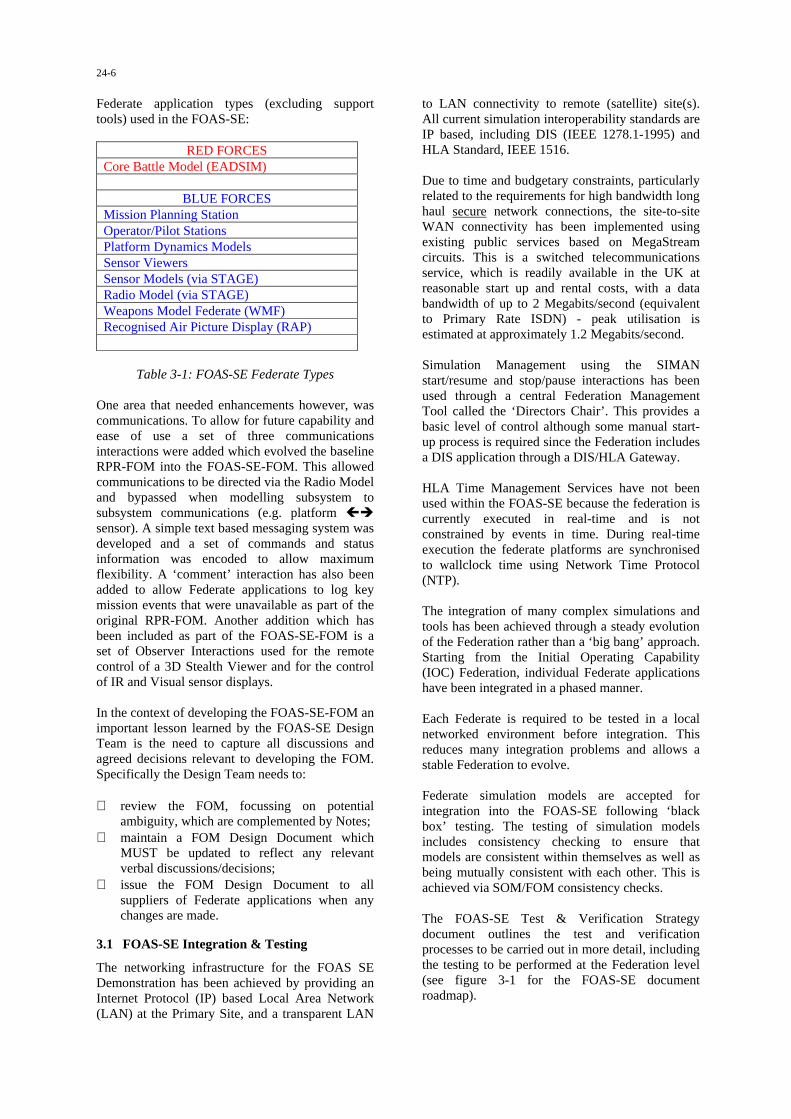
24-6
Federate application types (excluding supporttools) used in the FOAS-SE:
RED FORCESCore Battle Model (EADSIM)
BLUE FORCESMission Planning StationOperator/Pilot StationsPlatform Dynamics ModelsSensor ViewersSensor Models (via STAGE)Radio Model (via STAGE)Weapons Model Federate (WMF)Recognised Air Picture Display (RAP)
Table 3-1: FOAS-SE Federate Types
One area that needed enhancements however, wascommunications. To allow for future capability andease of use a set of three communicationsinteractions were added which evolved the baselineRPR-FOM into the FOAS-SE-FOM. This allowedcommunications to be directed via the Radio Modeland bypassed when modelling subsystem tosubsystem communications (e.g. platform ��
sensor). A simple text based messaging system wasdeveloped and a set of commands and statusinformation was encoded to allow maximumflexibility. A ‘comment’ interaction has also beenadded to allow Federate applications to log keymission events that were unavailable as part of theoriginal RPR-FOM. Another addition which hasbeen included as part of the FOAS-SE-FOM is aset of Observer Interactions used for the remotecontrol of a 3D Stealth Viewer and for the controlof IR and Visual sensor displays.
In the context of developing the FOAS-SE-FOM animportant lesson learned by the FOAS-SE DesignTeam is the need to capture all discussions andagreed decisions relevant to developing the FOM.Specifically the Design Team needs to:
⇒ review the FOM, focussing on potentialambiguity, which are complemented by Notes;
⇒ maintain a FOM Design Document whichMUST be updated to reflect any relevantverbal discussions/decisions;
⇒ issue the FOM Design Document to allsuppliers of Federate applications when anychanges are made.
3.1 FOAS-SE Integration & Testing
The networking infrastructure for the FOAS SEDemonstration has been achieved by providing anInternet Protocol (IP) based Local Area Network(LAN) at the Primary Site, and a transparent LAN
to LAN connectivity to remote (satellite) site(s).All current simulation interoperability standards areIP based, including DIS (IEEE 1278.1-1995) andHLA Standard, IEEE 1516.
Due to time and budgetary constraints, particularlyrelated to the requirements for high bandwidth longhaul secure network connections, the site-to-siteWAN connectivity has been implemented usingexisting public services based on MegaStreamcircuits. This is a switched telecommunicationsservice, which is readily available in the UK atreasonable start up and rental costs, with a databandwidth of up to 2 Megabits/second (equivalentto Primary Rate ISDN) - peak utilisation isestimated at approximately 1.2 Megabits/second.
Simulation Management using the SIMANstart/resume and stop/pause interactions has beenused through a central Federation ManagementTool called the ‘Directors Chair’. This provides abasic level of control although some manual start-up process is required since the Federation includesa DIS application through a DIS/HLA Gateway.
HLA Time Management Services have not beenused within the FOAS-SE because the federation iscurrently executed in real-time and is notconstrained by events in time. During real-timeexecution the federate platforms are synchronisedto wallclock time using Network Time Protocol(NTP).
The integration of many complex simulations andtools has been achieved through a steady evolutionof the Federation rather than a ‘big bang’ approach.Starting from the Initial Operating Capability(IOC) Federation, individual Federate applicationshave been integrated in a phased manner.
Each Federate is required to be tested in a localnetworked environment before integration. Thisreduces many integration problems and allows astable Federation to evolve.
Federate simulation models are accepted forintegration into the FOAS-SE following ‘blackbox’ testing. The testing of simulation modelsincludes consistency checking to ensure thatmodels are consistent within themselves as well asbeing mutually consistent with each other. This isachieved via SOM/FOM consistency checks.
The FOAS-SE Test & Verification Strategydocument outlines the test and verificationprocesses to be carried out in more detail, includingthe testing to be performed at the Federation level(see figure 3-1 for the FOAS-SE documentroadmap).
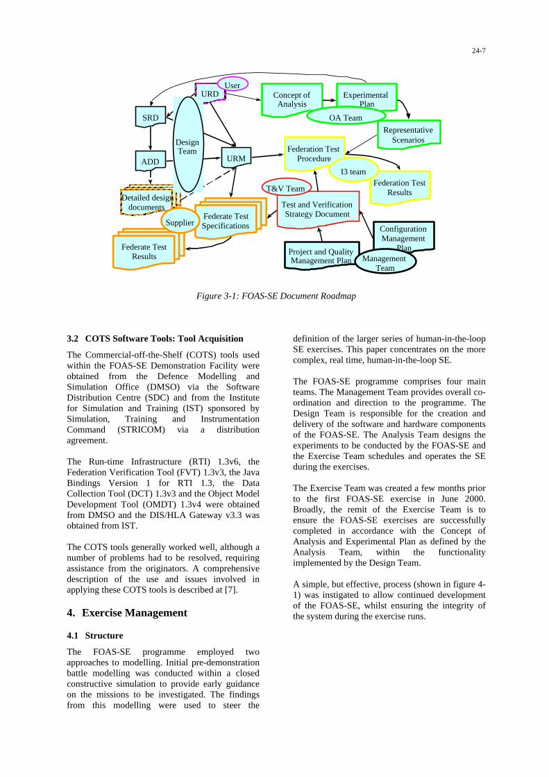
24-7
Test and VerificationStrategy Document
Project and QualityManagement Plan
ConfigurationManagement
Plan
Federate TestSpecifications
Federate TestResults
Federation TestResults
Federation TestProcedure
Concept ofAnalysis
ExperimentalPlan
RepresentativeScenarios
URM
URD
SRD
ADD
Detailed designdocuments
Supplier
ManagementTeam
I3 team
OA Team
DesignTeam
User
T&V Team
Figure 3-1: FOAS-SE Document Roadmap
3.2 COTS Software Tools: Tool Acquisition
The Commercial-off-the-Shelf (COTS) tools usedwithin the FOAS-SE Demonstration Facility wereobtained from the Defence Modelling andSimulation Office (DMSO) via the SoftwareDistribution Centre (SDC) and from the Institutefor Simulation and Training (IST) sponsored bySimulation, Training and InstrumentationCommand (STRICOM) via a distributionagreement.
The Run-time Infrastructure (RTI) 1.3v6, theFederation Verification Tool (FVT) 1.3v3, the JavaBindings Version 1 for RTI 1.3, the DataCollection Tool (DCT) 1.3v3 and the Object ModelDevelopment Tool (OMDT) 1.3v4 were obtainedfrom DMSO and the DIS/HLA Gateway v3.3 wasobtained from IST.
The COTS tools generally worked well, although anumber of problems had to be resolved, requiringassistance from the originators. A comprehensivedescription of the use and issues involved inapplying these COTS tools is described at [7].
4. Exercise Management
4.1 Structure
The FOAS-SE programme employed twoapproaches to modelling. Initial pre-demonstrationbattle modelling was conducted within a closedconstructive simulation to provide early guidanceon the missions to be investigated. The findingsfrom this modelling were used to steer the
definition of the larger series of human-in-the-loopSE exercises. This paper concentrates on the morecomplex, real time, human-in-the-loop SE.
The FOAS-SE programme comprises four mainteams. The Management Team provides overall co-ordination and direction to the programme. TheDesign Team is responsible for the creation anddelivery of the software and hardware componentsof the FOAS-SE. The Analysis Team designs theexperiments to be conducted by the FOAS-SE andthe Exercise Team schedules and operates the SEduring the exercises.
The Exercise Team was created a few months priorto the first FOAS-SE exercise in June 2000.Broadly, the remit of the Exercise Team is toensure the FOAS-SE exercises are successfullycompleted in accordance with the Concept ofAnalysis and Experimental Plan as defined by theAnalysis Team, within the functionalityimplemented by the Design Team.
A simple, but effective, process (shown in figure 4-1) was instigated to allow continued developmentof the FOAS-SE, whilst ensuring the integrity ofthe system during the exercise runs.

24-8
Activity
Development / Mission details
System Testing
Integration
Full Systems Testing
Rehearsals/missioninteraction testing
Operational exercise
Exercise review
Responsibility
Design Team / Analysis Team
Design Team
Design Team
Design Team
Exercise Team
Exercise Team
Analysis, Design& Exercise Teams
Figure 4-1: Basic FOAS-SE process
Development of the SE federate systems has beenan ongoing activity throughout the exercises.Typically, development takes place away from thecore FOAS-SE facility. When a component isready for insertion to the SE, a remote test of theamended federate system is conducted using a testharness environment. If this is successful, then thefederate is integrated within the FOAS-SE and afull systems test conducted within the realenvironment of the FOAS-SE, rather than the testharness.
At an agreed date before the next exercise,approximately one week, a stable FOAS-SEbaseline system is formally handed over to theExercise Team. This is then used for rehearsing theoperational exercise procedures and testing allconceivable mission interactions.
Based on the results of the rehearsals and missioninteraction testing, the exercise schedule is revisedif necessary. The operational exercise can thenbegin using a stable SE running known missions.Post-exercise run, a review session is held with allteams to identify lessons learnt and prioritiseactivities for the next phase.
All these activities are designed to minimise riskduring the operational run in order to maximise thenumber of valid mission runs achieved to optimisebenefit from the exercise. This process has been
very successful. Despite a number ofdevelopmental difficulties, a stable baseline hasalways been delivered. To date, there have not beenany non-recoverable systems failures observedunder exercise conditions.
4.2 FOAS-SE Configuration
The FOAS SE is comprised of a number ofcomputer models, simulation systems, operators,observers, military players and the processes foroperating all of these components and roles. Themain site for the FOAS-SE facility is DERAFarnborough. Two remote sites have beenconnected via a secure Wide Area Network(WAN), allowing up to three sites to participate inthe exercises: DERA Farnborough, BAESYSTEMS Warton and MBD Stevenage.
The first FOAS-SE exercise was run purely fromthe DERA Farnborough site and figure 4-2 showsthe layout of the SE.
The FOAS SE is a High Level Architecture (HLA)compliant federation, consisting of a number offederate systems interoperating through an agreedinterface – the Run Time Infrastructure (RTI).EADSIM (Extended Air Defence Simulation)provides the representation of all enemy forces andtargets. This is a constructive Computer GeneratedForce simulation system with detailed models offorce behaviours, which is largely prescriptive,with limited reactive capabilities. EADSIM is notHLA-compliant and so the HLA/DIS Gatewaysoftware provides the interfacing mechanismbetween the FOAS SE HLA federation and theEADSIM DIS network. The DIS Data Logger isthe only other system on the DIS network and isused to capture a record of DIS network activity forthe purposes of replay.
The main file server for the FOAS SE also runs theRTI software. The RTI, along with the FederationVerification Tool (FVT), is used to create thefederation and monitor the status of the federates asthey join the federation. Once all federates havejoined, the FVT is terminated due to its heavyprocessor load on the server.
A 2D Map Display federate provides a ground truthpicture of all forces and targets within the SE, aswell as information on these entities. A 3D Display(called a stealth display because it is passive withinthe federation, incurring minimal cost in terms ofnetwork traffic) provides a 3-dimensional view ofthe environment. The Data Collection Tool (DCT)records a log of all federation network activity tohelp support analysis of events after a mission run.

24-9
Single Site
CALCMMissionPlannerStation
Federate
CALCMOperatorStation 2Federate
CALCMDynamics
ModelFederate
RecognisedAir PictureFederate
RTI & FVTFederate
&File Server
HLA/DISGatewayFederate
EADSIMconstructivesimulation
DIS DataLogger2D Map
DisplayFederate
3D StealthDisplay
Federate
DataCollection
ToolsFederate
StageComms& HALEFederate
WeaponsModel
Federate&
BackupFile Server
CALCMOperatorStation 1Federate
Projector
BlueRoom
WhiteRoom
Display
Key:HLA network
DIS network
Figure 4-2: Diagram of FOAS SE for Exercise 1
MissionPlannerStation
Federate
UCAVOperatorStation
Federate
Common *Model
FederateRecognisedAir Picture &
Weapons ModelFederate
RTI & FVTFederate
&File Server
HLA/DISGatewayFederate
EADSIMconstructivesimulation
DIS DataLogger2D Map
DisplayFederate
3D StealthDisplay
Federate
DataCollection
ToolsFederate
StageComms& HALEFederate
BackupFile Server
Generic *OperatorStation(s)
Federate(s)
Projector
BlueRoom
WhiteRoom
Display
Key:HLA network
DIS network
Observernetworkanalyser
NetMeetingaudio, visual,
textcommunications
UCAVDynamics
ModelFederate
UCAVSensorView
Federate
* AARGM, ALUAV, CALCM, Dramatic, MALD, Stormshadow
ALUAVSensorView
Federate
NetMeetingaudio, visual, textcommunications
Farnborough
Figure 4-3: Diagram of Exercise 2 layout at DERA Farnbororough

24-10
New BuildFederate
2D MapDisplay
Federate
NetMeetingaudio, visual, textcommunications
MissionPlannerStation
Federate
Common *Model
Federate
Generic *OperatorStation(s)
Federate(s)
ALUAVSensorView
Federate
Warton
* AARGM, ALUAV, CALCM, Dramatic, MALD, Stormshadow
BlueRoom
EADSIMconstructivesimulation
Display
Key:HLA network
DIS network
Projector
Figure 4-4: Diagram of Exercise 2 layout at BAE SYSTEMS Warton
Common *Model
Federate
Generic *OperatorStation(s)
Federate(s)
NetMeetingaudio, visual, textcommunications
Stevenage
* AARGM, ALUAV, CALCM, Dramatic, MALD, Stormshadow
BlueRoom
Key:HLA network
DIS network
Figure 4-5: Diagram of Exercise 2 layout at MBD Stevenage
The Weapons Model Federate (WMF) determinesthe effects of certain Blue weapons within the SE.The Stage federate is used to provide thecommunications between Blue forces under controlfrom operator stations. This providedrepresentations of both satellite and High AltitudeLong Endurance (HALE) platforms. Stage alsoprovides the sensor information that stimulates theoperator sensor views.
A backup file server is also present. This maintainsa copy of data files from the main server, as well asthe ability to provide the RTI and FVT tools shouldthe main server become unavailable.
All the above systems reside in the ‘white’ room.This is designated ‘white’ as it contains bothexercise management tools, providing a groundtruth or white picture, and is the centre of
operations for the Red commander. A projectionfacility is also available to provide pictures from anumber of the federate computer screens in thewhite room. This display assists with themanagement of the mission run and is also usedduring debriefing to a larger audience.
The ‘Blue’ room houses information that wouldonly normally be available to Blue players. Forexercise 1, this consisted of federates providing amission planning station for defining routes and re-routing of the Conventional Air Launched CruiseMissiles (CALCMs), a CALCM operator station toissue commands to the CALCMs and the dynamicsmodel for the CALCMs. The only other system inthe Blue room is the Recognised Air Picture(RAP), which gives a time-delayed picture of thescenario, representative of the type of informationthat would be derived by the Blue Intelligence cell.

24-11
Exercise 2 built on the facility used during Exercise1. However, there were a number of significantdifferences between the two exercises. The maindistinctions being the increased number of federatesystems used and the distributed nature of Exercise2.
During the exercise, three geographically separatedsites comprised the SE. The main support site,hosting the white room functions, remained atDERA Farnborough. However, depending on theparticular missions run, the Blue room functionswere conducted across a combination of one ormore of the SE sites at DERA Farnborough, BAESYSTEMS Warton and MBD Stevenage. Thesesites are linked through 2Mbit Megastreamconnections, using MOD accredited encryptiondevices at each site.
Figure 4-3 shows the Exercise 2 layout for the SEat DERA Farnborough, which built on the originalExercise 1 configuration.
In addition to the Exercise 1 federates, thefollowing systems were introduced for Exercise 2.
The mission planning, operator and common modelfederates employed for Exercise 1 were originallyused solely to plan CALCM missions. Thesefederates were used during Exercise 2 as genericsystems for a range of Blue assets. The missionplanner, operator and common model federateswere used for Advanced Anti-Radiation GuidedMissiles (AARGM), Air Launched UninhabitedAir Vehicles (ALUAV), CALCMs, Dramaticmunitions, Mobile Air Launched Decoys (MALD)and Stormshadow missiles. In addition, the missionplanning station was used to create and send routesto the New Build 1 aircraft and the UninhabitedCombat Air Vehicles (UCAV).
The UCAV federates provide an operator station,model and sensor view for representing andcontrolling up to four UCAVs, using routesreceived from the generic mission planning station.In a similar fashion, the ALUAV federates utilisethe generic operator station and common model,with an ALUAV sensor viewer, to provide controlof the ALUAV craft.
As well as the HLA federates, two new (non-HLA)systems were introduced. The Observer networkanalyser package was used to monitor the networkstatus during SE use. Microsoft NetMeeting wasalso used, in conjunction with the Creative LabsWeb Cam II camera and microphone, to provideelectronic conferencing facilities between the sitesover the secure network.
Figure 4-4 shows the SE layout at BAE SYSTEMSWarton. This site was used for the New Build 1
missions, using the New Build 1 manned simulatorand automated aircraft, which often called forALUAVs to be flown in conjunction with the NewBuild 1 aircraft.
The third site was based at MBD Stevenage andwas used to assist with the running of CALCMswhen required. This is illustrated in figure 4-5.However, both the Warton and Stevenage siteswere capable of running varied configurationsusing the federate systems available at each site.The range of systems the common models wereable to support is listed in figures 4-4 & 4-5, withthe primary federate employed during Exercise 2highlighted in bold and underlined.
By the time of the second exercise, the FOAS-SEfacility comprised three separate sites, providing 24discrete HLA-compliant federate systems. Duringthe second exercise, some 17 missions wereconducted over 6 working days. The largestmission scenario consisted of 18 federates runningsimultaneously, modelling over 400 entities, acrossthree sites. Manning requirements for the largestmission run was approximately ten personnel,covering aircrew, operator, observer and exercisesupport functions. No unrecoverable systemfailures occurred during either of the exercises.
4.3 Running the exercise
A set of practical procedures was put in place inorder to operate the FOAS SE during the exerciseruns. The aim was to provide a formal structure andchain of command for the running of the exercisemissions. This section gives an overview of theprocesses used to manage the SE.
A structure around each mission run was created.This consisted of pre-mission set-up, briefing,initialisation, operation, closedown and debriefingstages. Initially it was possible to achieve twomission runs per day. However, once the exercisepersonnel were familiar with the procedures, anddepending on the length of the actual mission run(as the missions run in real time), it was possible toadapt the timings to readily achieve three missionruns per day.
The immediate chain of command for the exerciserevolved around three basic roles. The ExerciseDirector was ultimately responsible for theoperation of the SE and this lead function wassupported by two further roles, namely theAnalysis and Design Team leaders. Beforeinitiating a mission run, or making key decisions onthe nature of a mission or technical SE issues, theExercise Director would seek confirmation fromthe Analysis and Design Team leaders asappropriate.

24-12
The pre-mission set-up stage required the ExerciseSupport Team to provide a basic check that the SEwas ready to be used. This involved powering up(or rebooting) all relevant equipment and ensuringthe computers were safely logged in under theexercise accounts. A check was also made that allrequired personnel were present and ready.
The briefing stage was split into two sessions. Thefirst session was in the Blue room and coveredBlue mission details, the composition of the SE tobe used, roles for the mission and generalquestions. The second session took place in theWhite room and excluded Blue commandpersonnel. This session was primarily to inform theobservers of overall mission details andexpectations.
For distributed missions, where the Blue aircrew,operators and support staff were not all at the samesite, Microsoft NetMeeting was used for thebriefings. A combination of microphone/speakerand text-based NetChat communications wereused. This worked well, with the added bonus ofproviding a searchable log of communicationsbetween the sites were NetChat was used, and thiswas maintained throughout the briefing andoperational mission run. However, the nature ofNetChat meant that communications were brief,which allowed for some loss of clarity duringcertain mission explanations.
While the white briefing session was occurring, theSE initialisation process commenced. Thisinvolved an orderly run up sequence to bring all thecomponent systems into the SE. Due to thedevelopmental nature of some of the software andongoing testing of some of the SE systems, it wasnecessary to impose a rigorous, but known,procedure to bring the SE on-line in order to reduceany opportunity for unwanted effects. This resultedin an extremely stable SE.
A manual start initiated the exercise andoperational use of the SE. 0000hrs was definedfrom the simulation clock in the EADSIMconstructive simulation system. This occurredbefore the SE was fully operational (as EADSIMwas not necessarily the last component to enter theSE as part of the run-up procedures). Once all SEsystems were on-line, the instruction to begin themission run was made by the Exercise Director,authorising the Blue Commander to release theBlue forces.
During the mission run, all personnel had a seriesof questionnaire forms available for capturingnoteworthy events, from mission engagements tocomments on the SE functionality.
Once an ‘end game’ situation had been reached,and agreed between the Exercise Director, Analysisand Design Team leaders, the exercise was haltedand SE closedown procedures instigated. Thisinvolved a formal removal of systems from the SE,along with procedures for copying captured datafrom the systems to the main file server. From here,details for each mission were logged and recordedon CD as well as the daily backup tapes. Thisinformation was then made available to theAnalysis Team.
Debriefing was the final stage of the exerciseprocedures. For distributed missions, the debriefingtook place at the site with the Blue aircrew. Duringdebriefing, EADSIM was used to replay themission through the projection system for allexercise personnel. Verbal comments on themission were elicited and formally capturedthrough the questionnaires. Based on the debriefingsession, changes may result in the order ofsubsequent missions.
The end of the debriefing session marked thetermination of the procedures for the SE mission,pending any remaining data to be copied to theserver as part of the SE closedown procedures. TheSE was then available for the next mission.
4.4 Results
The detailed analysis of the FOAS-SEdemonstration is not due to take place until afterthe third exercise in October 2000, when all datahas been collected. At the time of writing, only twoof the three planned exercises have beenconducted. Preliminary analysis has taken placebetween each exercise, producing interim reports,and indeed it was possible to do some earlyanalysis during each exercise. However, the remitof this paper is not to cover the analysis findings,but to describe how the SE was employed tosupport the analysis process.
Before each exercise, the Analysis Team plannedout a series of mission experiments to conductduring the exercise. As a result of early analysisfindings during the exercise and feedback from thedebriefing sessions, an improved understanding ofthe issues involved was gained. This led to theability to better define the types of mission runsrequired to support the analysis process.
Mission planning therefore became an evolvingprocess, with many of the mission runs initiallyplanned for each exercise adapting as a result ofearly findings. This allowed the runs to focus onthe emerging key issues. Despite generally fittingin three mission runs per day, it was usuallypossible to modify the subsequent mission runs ona mission-by-mission basis without too much

24-13
difficulty. Such was the flexibility of the FOAS-SE.
5. Lessons Learnt
The FOAS-SE is a complex system comprisingvaried components, many of which remain underdevelopment. As with the production of any suchsystem, a number of problems had to be overcometo deliver a working baseline for each exercise.
An evolutionary method to building the FOAS-SEwas adopted, rather than a ‘big bang’ approach.This helps to reduce a number of integrationproblems by building on a stable, knownenvironment. One system at a time is added to theSE and tested. If necessary, the new federate orother components within the original federation,may be adapted in order to achieve a new, stablesystem.
Prior to integration testing with the FOAS-SE,federate systems were required to have undergonelocal checks using a test harness to provide arepresentation of the FOAS-SE environment.Having proved themselves in the local tests, newfederate systems would then be tested andintegrated with the latest stable FOAS-SE baseline.
Although this gradual approach to building theFOAS-SE is believed to have reduced a number ofdifficulties that may have occurred, severalproblems were still observed. The majority oftechnical issues centred on the stability of theconnection of a federate to the FOAS-SEfederation, and the ability of the federates to deliverthe specified functionality within the shorttimescale available.
It would often be the case that a system wouldwork as specified under local testing conditions,but not within the actual FOAS-SE environment.Resolving some of these problems could take asignificant time. Part of this difficulty was due tothe fact that much of the FOAS-SE was underparallel development and so the test harness couldnot be fully representative of the actual FOAS-SEenvironment; the test harness always being severalevolutions behind the latest baseline.
This problem was significantly reduced however,when developments to systems were conducted atthe FOAS-SE facility. This provided anenvironment where the actual SE could be used forlocal testing rather than the isolated test harness,and also developers were able to more easilycommunicate with other system developers to helpkeep abreast of changes.
The other key aspect to improving the likelysuccess of an ‘easy’ integration, was the captureand communication of all technical decisions,particularly regarding FOM interface development.Procedures were in place to record such decisionsand changes to the FOAS-SE and, in particular, theFOM Design Document. However, themaintenance and dissemination of this informationcould have been improved. Often time pressureswould restrict the extent to which these procedurescould be followed.
Limitations and constraints within the FOAS-SEled to the Analysis Team having to make a numberof assumptions before interpreting the datagathered from the exercises. A balance had to bestruck between delivering a SE that did not requiretoo many assumptions to be made that mightinvalidate the results, and producing a workingsystem within the time constraints imposed by theneed to support the FOAS submission for InitialGate approval. The main factors resulting inassumptions are discussed below.
Maintaining a complete audit trial of the dataunderlying many of the models used in the SE wasdifficult. The employment of a formal DataManager role to take responsibility for this wouldhave reduced the uncertainty associated with someof the data.
Limited functionality in the SE, due to both thedevelopmental nature of some of the systems, andinherent limitations in others, resulted in a numberof assumptions being made. Whatever systems areused, there will always be limitations with SE as,by their nature, SE will always be abstractions.Obtaining a reasonable balance of functionality,cost, time and prioritisation of ongoingdevelopments reduces the assumptions that willinevitably have to be made.
The necessary involvement of the exercise aircrewin the preparation and testing of the SE resulted ina degree of ‘learning the game’. Plans to applymultiple variations of the enemy threat for the thirdexercise should help to reduce this problem.Another approach, not possible with the existingprescripted simulation used to model enemy forces,is to provide a simulation system that allows theenemy commander to interactively change theenemy behaviour during a mission. Although thiswould require the isolation of the enemy commandcell from the general exercise control systems.
During the distributed missions, communicationbetween sites was limited by the audio, visual andtext based systems available. The NetChat facilityprovides an excellent, searchable record of events,but is time consuming to use and restricts the

24-14
quality and quantity of information conveyed.Virtual whiteboarding will be investigated for thethird exercise to help improve the briefing process.Improved audio systems are also being employedto enhance the existing system, which provides apoor quality telecommunication facility that againrestricted much needed communication betweenthe sites.
6. Conclusions
In terms of meeting the original objectives, asspecified at [5], the FOAS-SE has to date shownthe following traits.
Initial Monte-Carlo simulation runs wereconducted to steer the subsequent real time,human-in-the-loop exercises. To date, two mainexercises have been conducted using the FOAS-SE,with the third and final run about to commence atthe time of writing. These exercises haveinvestigated some of the FOAS concepts within aco-ordinated, coalition air-attack scenario.Numerous runs have been conducted to study arange of missions.
DERA Farnborough hosts the core facility and thefirst FOAS-SE exercise was conducted from thislocation. The second and planned third exercisesmade use of the two remote sites at BAESYSTEMS Warton and MBD Stevenage,demonstrating real time, secure connections.
Although detailed analysis remains to beconducted, initial findings suggest that the FOAS-SE has improved the general understanding of theFOAS concept and provides a common forumthrough which this concept can be furthercommunicated and developed.
Preliminary results have already been fed in to theongoing FOAS OA, backed up by a significantamount of data obtained from the exercise missionruns. Various force mix combinations have beenexercised in order to improve understanding ofdifferent force mixes on the tactics employed andresulting mission effectiveness. Although thefindings are dependent on a number ofassumptions.
The SE proved to be extremely robust and quick toreconfigure, enabling a flexible approach to beadopted that allowed the best use of availablesoftware and experiment time.
For potential FOAS product suppliers the FOAS-SE Demonstration offers an opportunity to gain anunderstanding of the FOAS User Requirements andto assess the effectiveness of their proposedsolutions.
For the UK simulation/SE community thedemonstration offers an opportunity to gain earlyvisibility of and participation in the expectedlonger-term implementation of SEs on the FOASprogramme.
The study has also provided a foundation fromwhich FOAS-SE activities can expand bygenerating data to support future SE investmentcases and giving UK Industry an early involvementin the application of SEs to the FOAS Programme.Indeed, it is already planned to use the FOAS-SEfacility to support Industry in other studies shortlyafter the third FOAS-SE exercise.
In the longer term, SEs may be used to increaseconfidence and knowledge in many areas of theFOAS programme, e.g.
⇒ requirements capture;⇒ CONOPS development;⇒ operational employment;⇒ training and mission rehearsal;⇒ test and evaluation;⇒ acquisition;⇒ research and development;⇒ warfare analysis.
Traditionally, acquisition has been a linear andsequential process; the implementation of SeBAwithin FOAS aims to make the acquisition processmore concurrent. This policy is consistent with theprinciples of Smart Procurement within the UK.
The core SE HLA facility now exists, with theinfrastructure providing an experimentalenvironment for exploitation by model developers,both related to FOAS and generally for the SEcommunity.
It is believed that the FOAS-SE has successfullydemonstrated the ability of SE to providesignificant assistance within the acquisitionprocess.
7. References
[1] D/DG(R&T)/8/6/1/1, "MOD SE Policy Paper",May 1999.
[2] Colin Rayment. “Synthetic Theatre of WarOverview”, Proceedings of the FirstInternational Synthetic EnvironmentsSymposium, RMCS Shrivenham, October1998.
[3] Neil Smith, Paul Henry, & Chris Rouget. "UKProject FlasHLAmp Warfighting Federation",SIW paper #98S-SIW-067, Spring 1998 SISOConference.
24-15
[4] Mike Jobson. "UK Project FlasHLAmpAnalysis Federation", SIW paper #98S-SIW-070, Spring 1998 SISO Conference.
[5] S.J. Cobb & R.R. Woodburn. “The Use of aTwin Level Synthetic Environment in theDevelopment of the Future Offensive AirSystem”, Proceedings of the First InternationalSynthetic Environments Symposium, RMCSShrivenham, October 1998.
[6] Chris Rouget & Paul Henry. “Utilizing HLAObject Models within a C++ Repository togenerate tools to support the FederationDevelopment and Execution Process”, SIWpaper #00S-SIW-095, Spring 2000 SISOConference.
[7] Kelvin Martin, Chris Rouget, & Neil Smith.“Design and development of a SyntheticEnvironment (SE) Demonstrator for the UKFuture Offensive Air System (FOAS)”, Fall2000 SISO Conference.
Acknowledgements
The authors of this paper would like toacknowledge the assistance of the FOAS-SEpartners for their co-operation during theproduction of this paper. The success of the FOAS-SE is very much due to a team effort.
This paper also draws heavily upon findingspresented at [7], of which Chris Rouget was asignificant contributing author, and the initialfindings from the FOAS-SE Analysis Team led byJenny Young. The authors gratefully acknowledgetheir support.
The opinions expressed in this paper remain thoseof the authors.
Author Biographies
KELVIN MARTIN is a Principal SoftwareEngineer working for Matra BAe Dynamics (UK)and has worked in the field of Simulation andModelling for 15 years. A graduate of ManchesterUniversity he has been involved with the softwaredesign and development of Air Defence TrainingEquipment. He is presently working in the MatraBAe Dynamics Synthetic Environment AppliedResearch Laboratory. The purpose of his currentresearch is to apply and evaluate SE standards and
Advanced Distributed Simulation technology tocurrent and future systems, including advancedguided missiles and ground based air defenceconcepts. Since 1996 he has been involved with anumber of UK SE National Demonstrationprogrammes including FlasHLAmp and ADSE (AirDefence Synthetic Environment).
NEIL SMITH is a Senior Professional Scientistworking for the UK Defence Evaluation &Research Agency (DERA) and is presentlyworking for Flight Management and ControlDepartment (Air Systems Sector) at DERABedford. Since joining the DERA (then known asthe Royal Aircraft Establishment) in 1972 he hasgained over 25 years experience in the use ofsimulation technology for piloted flight simulationapplications. Since 1992 he has been involved witha range of UK research projects which haveprovided a focus on the application of methods andtechniques to integrate fight simulation systems aspart of a larger scale networked simulationenvironments. These studies have involved theapplication of Standards for Distributed InteractiveSimulation (DIS), in addition to managing theimplementation of distributed simulationframeworks using the High Level Architecture. Thepurpose of this research work is to determine thescope and potential use of emerging distributedsimulation standards and technology with respectto the integration of high performance, human-in-the-loop simulations.
IAN PAGE is the Synthetic EnvironmentsApplications Team Leader at the UK DefenceEvaluation & Research Agency (DERA) within theBattlefield Management Systems Department(Knowledge Information Systems Sector). AnApplied Biology graduate of the Liverpool JohnMoores University and a Computer Studies post-graduate of the Sheffield Hallam University, he isalso a professional member of the British ComputerSociety. Ten years at DERA have involvednumerous roles including developing knowledgebased systems, leading research in to geotypicalterrain generation, behavioural modelling researchand management of the Synthetic Forces teamduring the latter years of the Synthetic Theatre ofWar research programme. Current projects includemanaging research into web-based techniques for aSE Infrastructure and Services site, SE consultancyfor the SeBA Acquisition Management Systemweb site, and Exercise Director for the FOAS-SE.
British Crown copyright 2000. Published with the permission of the Defence Evaluationand Research Agency on behalf of the Controller of HMSO.

This page has been deliberately left blank
Page intentionnellement blanche

CR-1
Conference Closing Remarks
Major-General Andrew FigguresCapability Manager (Manoeuvre)
MoD Main BuildingWhitehall, London SW1A 2HB
United Kingdom
Paper presented at the RTO NMSG Conference on “The Second NATO Modelling and SimulationConference”, held in Shrivenham, UK, 24-26 October 2000, and published in RTO MP-071.

This page has been deliberately left blank
Page intentionnellement blanche

REPORT DOCUMENTATION PAGE
1. Recipient’s Reference 2. Originator’s References 3. Further Reference 4. Security Classificationof Document
RTO-MP-071 ISBN 92-837-1069-X UNCLASSIFIED/AC/323(NMSG-010)TP/1 UNLIMITED
5. Originator Research and Technology OrganizationNorth Atlantic Treaty OrganizationBP 25, 7 rue Ancelle, F-92201 Neuilly-sur-Seine Cedex, France
6. TitleThe Second NATO Modelling and Simulation Conference
7. Presented at/sponsored by
the RTO NATO Modelling and Simulation Group (NMSG) Conferenceheld in Shrivenham, UK, 24-26 October 2000.
8. Author(s)/Editor(s) 9. Date
Multiple July 2001
10. Author’s/Editor’s Address 11. Pages
Multiple 190 (text)670 (slides)
12. Distribution Statement There are no restrictions on the distribution of this document.Information about the availability of this and other RTOunclassified publications is given on the back cover.
13. Keywords/Descriptors
Computerized simulation Remote sensingModels StandardsNATO CAX (Computer Assisted Exercises)Human factors engineering Modelling and SimulationResearch projects Synthetic environmentsDecision making Environmental dataMilitary training
14. Abstract
The conference presented a series of papers in plenary sessions that were designed to providean overview of NATO M&S current best practice, standards, interoperability and reuse. TheConference also provided information on NATO M&S policy, and new M&S activities withinthe Alliance.

This page has been deliberately left blank
Page intentionnellement blanche
NORTH ATLANTIC TREATY ORGANIZATION
RESEARCH AND TECHNOLOGY ORGANIZATION
BP 25 • 7 RUE ANCELLE DIFFUSION DES PUBLICATIONS
F-92201 NEUILLY-SUR-SEINE CEDEX • FRANCE RTO NON CLASSIFIEES
Telecopie 0(1)55.61.22.99 • E-mail [email protected]
L’Organisation pour la recherche et la technologie de l’OTAN (RTO), d´etient un stock limit´e de certaines de ses publications r´ecentes, ainsique de celles de l’ancien AGARD (Groupe consultatif pour la recherche et les r´ealisations a´erospatiales de l’OTAN). Celles-ci pourronteventuellement ˆetre obtenues sous forme de copie papier. Pour de plus amples renseignements concernant l’achat de ces ouvrages,adressez-vous par lettre ou par t´elecopie a l’adresse indiqu´ee ci-dessus. Veuillez ne pas t´elephoner.
Des exemplaires suppl´ementaires peuvent parfois ˆetre obtenus aupr`es des centres nationaux de distribution indiqu´es ci-dessous. Si voussouhaitez recevoir toutes les publications de la RTO, ou simplement celles qui concernent certains Panels, vous pouvez demander d’etreinclus sur la liste d’envoi de l’un de ces centres.
Les publications de la RTO et de l’AGARD sont en vente aupr`es des agences de vente indiqu´ees ci-dessous, sous forme de photocopie oude microfiche. Certains originaux peuvent ´egalement ˆetre obtenus aupr`es de CASI.
CENTRES DE DIFFUSION NATIONAUX
ALLEMAGNE FRANCE PAYS-BASStreitkrafteamt / Abteilung III O.N.E.R.A. (ISP) NDRCCFachinformationszentrum der 29, Avenue de la Division Leclerc DGM/DWOOBundeswehr, (FIZBw) BP 72, 92322 Chˆatillon Cedex P.O. Box 20701
Friedrich-Ebert-Allee 34 2500 ES Den HaagGRECE (Correspondant)D-53113 Bonn
Hellenic Ministry of National POLOGNEBELGIQUE Defence Chief of International Cooperation
Coordinateur RTO - VSL/RTO Defence Industry Research & DivisionEtat-Major de la Force A´erienne Technology General Directorate Research & Development DepartmentQuartier Reine Elisabeth Technological R&D Directorate 218 Niepodleglosci Av.Rue d’Evere, B-1140 Bruxelles D.Soutsou 40, GR-11521, Athens 00-911 Warsaw
HONGRIECANADA PORTUGALDepartment for ScientificServices d’information scientifique Estado Maior da For¸ca AereaAnalysispour la defense (SISD) SDFA - Centro de Documenta¸cao
Institute of Military TechnologyR et D pour la d´efense Canada AlfragideMinistry of DefenceMinistere de la D´efense nationale P-2720 AmadoraH-1525 Budapest P O Box 26Ottawa, Ontario K1A 0K2
REPUBLIQUE TCHEQUEISLANDEDANEMARK Distribuc∨ nı a informac∨ nı str∨ edisko R&T
Director of AviationDanish Defence Research Establishment VTUL a PVO Prahac/o FlugradRyvangs Alle 1, P.O. Box 2715 Mladoboleslavsk´a ul.ReykjavikDK-2100 Copenhagen Ø 197 06 Praha 9-Kbely AFB
ITALIEESPAGNE ROYAUME-UNICentro di DocumentazioneINTA (RTO/AGARD Publications) Defence Research Information CentreTecnico-Scientifica della DifesaCarretera de Torrej´on a Ajalvir, Pk.4 Kentigern House
Via XX Settembre 123a28850 Torrej´on de Ardoz - Madrid 65 Brown Street00187 Roma Glasgow G2 8EX
ETATS-UNISLUXEMBOURGNASA Center for AeroSpace TURQUIE
Voir BelgiqueInformation (CASI) Mill ı Savunma Bas,kanli i (MSB)Parkway Center ARGE Dairesi Bas,kanli i (MSB)NORVEGE7121 Standard Drive 06650 Bakanliklar - AnkaraNorwegian Defence ResearchHanover, MD 21076-1320 Establishment
Attn: BiblioteketP.O. Box 25, NO-2007 Kjeller
AGENCES DE VENTE
NASA Center for AeroSpace The British Library Document Canada Institute for Scientific andInformation (CASI) Supply Centre Technical Information (CISTI)
Parkway Center Boston Spa, Wetherby National Research Council7121 Standard Drive West Yorkshire LS23 7BQ Document DeliveryHanover, MD 21076-1320 Royaume-Uni Montreal Road, Building M-55Etats-Unis Ottawa K1A 0S2, Canada
Les demandes de documents RTO ou AGARD doivent comporter la d´enomination “RTO” ou “AGARD” selon le cas, suivie dunumero de s´erie (par exemple AGARD-AG-315). Des informations analogues, telles que le titre et la date de publication sontsouhaitables. Des r´eferences bibliographiques compl`etes ainsi que des r´esumes des publications RTO et AGARD figurent dans lesjournaux suivants:
Scientific and Technical Aerospace Reports (STAR) Government Reports Announcements & Index (GRA&I)STAR peut etre consult´e en ligne au localisateur de publi´e par le National Technical Information Serviceressources uniformes (URL) suivant: Springfield
http://www.sti.nasa.gov/Pubs/star/Star.html Virginia 2216STAR est edite par CASI dans le cadre du programme Etats-UnisNASA d’information scientifique et technique (STI) (accessible ´egalement en mode interactif dans la base de
donnees bibliographiques en ligne du NTIS, et sur CD-ROM)STI Program Office, MS 157ANASA Langley Research CenterHampton, Virginia 23681-0001Etats-Unis
Imprime par St-Joseph Ottawa/Hull(Membre de la Corporation St-Joseph)
45, boul. Sacre-Cœur, Hull (Quebec), Canada J8X 1C6

NORTH ATLANTIC TREATY ORGANIZATION
RESEARCH AND TECHNOLOGY ORGANIZATION
BP 25 • 7 RUE ANCELLE DISTRIBUTION OF UNCLASSIFIED
F-92201 NEUILLY-SUR-SEINE CEDEX • FRANCE RTO PUBLICATIONS
Telefax 0(1)55.61.22.99 • E-mail [email protected]
NATO’s Research and Technology Organization (RTO) holds limited quantities of some of its recent publications and those of the formerAGARD (Advisory Group for Aerospace Research & Development of NATO), and these may be available for purchase in hard copy form.For more information, write or send a telefax to the address given above. Please do not telephone.
Further copies are sometimes available from the National Distribution Centres listed below. If you wish to receive all RTO publications, orjust those relating to one or more specific RTO Panels, they may be willing to include you (or your organisation) in their distribution.
RTO and AGARD publications may be purchased from the Sales Agencies listed below, in photocopy or microfiche form. Original copiesof some publications may be available from CASI.
NATIONAL DISTRIBUTION CENTRES
BELGIUM GREECE (Point of Contact) POLANDCoordinateur RTO - VSL/RTO Hellenic Ministry of National Chief of International CooperationEtat-Major de la Force A´erienne Defence DivisionQuartier Reine Elisabeth Defence Industry Research & Research & DevelopmentRue d’Evere, B-1140 Bruxelles Technology General Directorate Department
Technological R&D Directorate 218 Niepodleglosci Av.CANADA D.Soutsou 40, GR-11521, Athens 00-911 Warsaw
Defence Scientific InformationServices (DSIS) HUNGARY PORTUGAL
Defence R&D Canada Department for Scientific Estado Maior da For¸ca AereaDepartment of National Defence Analysis SDFA - Centro de Documenta¸caoOttawa, Ontario K1A 0K2 Institute of Military Technology Alfragide
Ministry of Defence P-2720 AmadoraCZECH REPUBLIC H-1525 Budapest P O Box 26
SPAINDistribuc∨ nı a informac∨ nı str∨ edisko R&TICELAND INTA (RTO/AGARD Publications)VTUL a PVO Praha
Director of Aviation Carretera de Torrej´on a Ajalvir, Pk.4Mladoboleslavsk´a ul.c/o Flugrad 28850 Torrej´on de Ardoz - Madrid197 06 Praha 9-Kbely AFBReykjavik
TURKEYDENMARKITALY Mill ı Savunma Bas,kanli i (MSB)Danish Defence Research
Centro di DocumentazioneEstablishment ARGE Dairesi Bas,kanli i (MSB)Tecnico-Scientifica della DifesaRyvangs Alle 1, P.O. Box 2715 06650 Bakanliklar - Ankara
Via XX Settembre 123aDK-2100 Copenhagen ØUNITED KINGDOM00187 Roma
FRANCE Defence Research InformationLUXEMBOURGO.N.E.R.A. (ISP) Centre
See Belgium29 Avenue de la Division Leclerc Kentigern HouseBP 72, 92322 Chˆatillon Cedex 65 Brown Street
NETHERLANDS Glasgow G2 8EXNDRCCGERMANYDGM/DWOOStreitkrafteamt / Abteilung III UNITED STATESP.O. Box 20701Fachinformationszentrum der NASA Center for AeroSpace2500 ES Den HaagBundeswehr, (FIZBw) Information (CASI)
Friedrich-Ebert-Allee 34 Parkway CenterNORWAYD-53113 Bonn 7121 Standard Drive
Norwegian Defence Research Hanover, MD 21076-1320Establishment
Attn: BiblioteketP.O. Box 25, NO-2007 Kjeller
SALES AGENCIESNASA Center for AeroSpace The British Library Document Canada Institute for Scientific and
Information (CASI) Supply Centre Technical Information (CISTI)Parkway Center Boston Spa, Wetherby National Research Council7121 Standard Drive West Yorkshire LS23 7BQ Document DeliveryHanover, MD 21076-1320 United Kingdom Montreal Road, Building M-55United States Ottawa K1A 0S2, CanadaRequests for RTO or AGARD documents should include the word ‘RTO’ or ‘AGARD’, as appropriate, followed by the serialnumber (for example AGARD-AG-315). Collateral information such as title and publication date is desirable. Full bibliographicalreferences and abstracts of RTO and AGARD publications are given in the following journals:
Scientific and Technical Aerospace Reports (STAR) Government Reports Announcements & Index (GRA&I)STAR is available on-line at the following uniform published by the National Technical Information Serviceresource locator: Springfield
http://www.sti.nasa.gov/Pubs/star/Star.html Virginia 22161STAR is published by CASI for the NASA Scientific United Statesand Technical Information (STI) Program (also available online in the NTIS BibliographicSTI Program Office, MS 157A Database or on CD-ROM)NASA Langley Research CenterHampton, Virginia 23681-0001United States
Printed by St. Joseph Ottawa/Hull(A St. Joseph Corporation Company)
45 Sacre-Cœur Blvd., Hull (Quebec), Canada J8X 1C6
ISBN 92-837-1069-X