Embed Size (px)
Citation preview

THE SELECTION AND TESTING OF COMPRESSION SEAL AND
CHAMBER COATING MATERIALS FOR THE PIVOTAL ENGINE™.
____________________________
A thesis
submitted in partial fulfilment
of the requirements for the Degree
of
Master of Mechanical Engineering
in the
University of Canterbury
by
D. J. Miller
___________
University of Canterbury
2006

1
Abstract.
Wear and friction tests were conducted on a rotational tribometer to identify material
couples for compression seals and chamber coatings to extend the service life of the
Pivotal Engine™. Potential materials were identified based on reports in the literature
of successful use in similar environments. From the rotational tribometer tests, the
best material couple was found to be reaction bonded silicon nitride against a Sulzer
Metco F4301 plasma sprayed coating followed by a Total Seal TiN coated seal
against the F4301 coating. However, the performance predicted by the rotational
tribometer was not realised in a fired engine, where the TiN coated seal wore almost
as fast as an uncoated seal. This discrepancy was due to the large differences in
operating conditions between the rotational tribometer and the fired engine,
particularly the reciprocating motion of the engine. The different operating conditions
mean that the results from the rotational tribometer have little or no relevance actual
performance in the engine.
To overcome the limitations of the rotational tribometer a reciprocating tribometer
was designed and built. The performance predicted by the reciprocating tribometer
was much closer to the observed wear rates from the engine, particularly with the
Total Seal TiN coated seals. Some of the results from the reciprocating tribometer
were a direct-contradiction to those obtained on the rotational tribometer. When tested
on the rotational tribometer the nitrided stainless steel seal wear rate was lower than
that of the Mazda cast iron seal. However, on the reciprocating tribometer the Mazda
cast iron seal had a lower wear rate than the nitrided stainless steel seal. From the
testing conducted on the reciprocating tribometer the best material couple was found
to be Total Seal TiN coated seals on the F4301 chamber coating. However, this
material couple cannot be recommended to increase the seal life in the Pivotal
Engine™ because at the conclusion of a twenty hour test the Total Seal TiN coating
had worn through to the substrate. In addition to testing different materials, different
oils were tested while keeping the wear couple constant. The oil that offered the best
wear protection to both the seal and chamber coating was Castrol A747. These tests
showed that different oils have as much effect as different materials.

2
Even with the best material combinations (Total Seal TiN seal, F4301 chamber
coating) the seal wear rates in the Pivotal Engine™ are much higher than would be
expected in other engines. This leads to the hypothesis that the origin of high seal
wear in the Pivotal Engine™ is not due to material properties, but to design issues.
The most likely problem is distortion of the chamber, which causes high localised seal
loadings, and in turn causing high seal wear.

3
ABSTRACT. 1
I. INTRODUCTION 5
II. BACKGROUND. 9
II.A. Piston Engine Seal Design. 9 II.A.1. Piston Ring Profiles. 11 II.A.2. Piston Ring Dynamics. 13 II.A.3. Piston Ring Tribology. 15 II.A.4. Lubrication and Lubricants. 16
II.B. Mazda 13BT Rotary Seal Design (Wankel engine). 18
II.C. Non-Metallic Seal Materials. 20 II.C.1. Ceramic Tribology. 20 II.C.2. Thin Film Tribology. 22
II.D. Tribological Testing. 24 II.D.1. Fired Engine Tests. 25 II.D.2. Motored Engine Tests. 25 II.D.3. Tribometer Tests. 26
II.E. Wear Measurement. 27
III. PROCEDURE. 28
III.A. Equipment. 28 III.A.1. Rotational Tribometer. 28 III.A.2. Reciprocating Tribometer. 30 III.A.3. Other Equipment. 38
III.B. Material Test Procedure. 39 III.B.1. Rotational Tribometer Test Procedure. 39 III.B.2. Rotational Tribometer Test Procedure for Low Wear Material Systems. 41 III.B.3. Reciprocating Tribometer Test Procedure. 43
IV. RESULTS AND DISCUSSION. 44
IV.A. Material Selection. 44 IV.A.1. Compression Seal Materials. 44 IV.A.2. Chamber Materials. 44
IV.B. Material Characterisation. 46 IV.B.1. Nitrided Stainless Steel. 46 IV.B.2. Mazda 13BT Apex Seal (Cast Iron). 47 IV.B.3. Silicon Nitride. 49 IV.B.4. Titanium Nitride Coated N-SS. 50 IV.B.5. Chromium Nitride Coated N-SS. 52 IV.B.6. Tungsten Carbide-Carbon Coated N-SS. 52 IV.B.7. Diamond like Carbon Coated N-SS. 53 IV.B.8. Other PVD Coated Seals. 54 IV.B.9. Plasma Nitrided Titanium. 54 IV.B.10. Pivotal Engineering 75B-90MXC Coating. 54 IV.B.11. Sulzer Metco F4301. 56

4
IV.B.12. Sulzer Metco XPT512 and F2056. 58 IV.B.13. NASA PS304. 61
IV.C. Rotational Tribometer Mass Loss Wear Results. 64 IV.C.1. Nitrided Stainless Steel Seals Rotational Wear Test Results. 66 IV.C.2. Mazda 13B Apex Seal (Cast Iron). 68 IV.C.3. PVD Coated Seals. 68 IV.C.4. Summary of Rotational Mass Loss Tests. 69
IV.D. Extended Duration Tests. 70 IV.D.1. PVD Coated Seals. 70 IV.D.2. Silicon Nitride Seals. 71
IV.E. Fired Engine Test Results. 76 IV.E.1. Compression Seal Analysis. 77 IV.E.2. Alternative Compression Seal Designs. 79 IV.E.3. Other Factors. 81
IV.F. Reciprocating Tribometer. 84 IV.F.1. Reciprocating Tribometer Results. 84 IV.F.2. Test Block Surface Analysis. 87 IV.F.3. Lubricant Tests. 90
V. CONCLUSIONS. 92
V.1. Recommended Future Work. 93
REFERENCES. 95

5
I. Introduction Pivotal Engineering, a subsidiary of Christchurch based company Mace Engineering,
was formed to develop the Pivotal Engine™. The Pivotal Engine™ was intended to
overcome some of the inherent problems associated with a conventional two-cycle
engine, such as high piston and piston ring wear rates and friction losses due to piston
tilt and large port openings, reliability problems due to lack of control over piston
temperatures and high oil consumption. The Pivotal Engine™ is an Otto cycle two-
cycle engine, assembled from 500cc modules in either parallel twin or opposed four
configurations with approximate power outputs of 100 hp and 200 hp respectively.
The Pivotal Engine™ utilises a piston of rectangular section that pivots on a bearing
at one end with a conventional con-rod and crankshaft, similar to the concept
developed by Richard James Cylindrical Motors Ltd [1]. The Pivotal Engine™ is
shown in Figure 1 with a side plate removed and the piston at top and bottom dead
centres (TDC and BDC respectively), showing the seal and port arrangement (note the
piston shown has a modified compression seal arrangement, the actual piston and
compression seal arrangement is shown in Figure 2).
The pivoting design of the piston allows coolant to be introduced through the pivot
point on one side of the piston, travel through a channel under the combustion
chamber, and exit through the second pivot point. The ability to entrain coolant into
the piston facilitates active temperature control of the piston, all but eliminating the
possibility of piston seizure due to overheating, and the cooler combustion chamber
will reduce NOX emissions. Because the piston in the Pivotal Engine™ is
constrained radially through the use of plain bearings, the sole function of the piston
skirt is to close the transfer and exhaust ports during the compression stroke. A
conventional engine relies on the piston skirt to stabilise the piston against the
cylinder, which increases friction. However these properties have associated
disadvantages. Any heat removed from the combustion chamber through cooling will
reduce the energy available to be converted into useful work, in turn reducing the
overall engine efficiency. The potentially lower temperature in the combustion
chamber will also increase the amount of un-burnt hydrocarbons in the exhaust
compared to a conventional engine.

6
For each piston in the Pivotal Engine™ there are three compression seals, two side
seals and a front seal. These seals perform the same function as a piston ring in a
conventional engine. The two side seals interlock with the front seal (detailed in
Figure 2). Due to the piston geometry, it is necessary for the compression seals to be
fitted to the piston with tight clearances. This, essentially prevents the seal from tilting
in the piston and ensures normality to the side plate or exhaust block at all times.
Sealing force is provided by springs and combustion pressure acting on the piston side
of the seal. All three of these seals are wearing at an unacceptably high rate, limiting
the life of the engine. The sealing system of the Pivotal Engine™ has similarities with
both a conventional piston engine and a Wankel rotary engine. The requirement of a
gas tight seal in a 90° corner is similar to the apex, side and corner seals in the
Wankel engine. However, the temperature and lubrication conditions in the Wankel
engine are more severe and the seals in the Wankel engine do not move in a
reciprocating motion. The temperature, lubrication and dynamics (reciprocating
motion) in the Pivotal Engine™ are similar to a conventional two-cycle engine.
Figure 1. Pivotal™ Engine with side plate removed. (A) piston above TDC, (B) piston below
BDC.
Figure 2. Piston and compression seals.

7
In most instances, the service life of a two-cycle engine is determined by the ability of
the piston ring (compression seal) to seal combustion pressure from the crankcase. As
the seal wears, its ability to seal reduces until the engine no longer produces sufficient
power or fails catastrophically (i.e. broken piston ring). Therefore, it can be construed
that the service life of a two-cycle engine is strongly determined by the life of the
piston ring-cylinder liner system. In the case of the Pivotal Engine™ the current seal
and chamber materials have a service life of less than 50 hours. Such a short life is
unacceptable since for example, a service life of 600 hours is required for use as a
power unit for a sports plane. It is also hoped that the Pivotal Engine™ will be
utilised for a variety of other applications such as power generation and possibly
automotive applications, all of which obviously require a long service life. The
present research is therefore aimed at minimising the high wear rates experienced by
the compression seals in the Pivotal Engine™, which lead to an unacceptably short
service life.
To maximise the service life of the Pivotal Engine™, wear and friction experiments
have been conducted to identify material couples that produce minimal wear. These
materials include: metals, ceramics, thin film coatings, solid lubricating materials and
various plasma sprayed materials. The testing of potential materials is required
because wear is not a material property but a system parameter, influenced by many
factors including, but not limited to: hardness, velocity, temperature, loads, lubricants
and friction power intensity. All of these factors must be considered when conducting
wear and friction experiments.
At the inception of this project, a rotational wear tester was made available. It was
initially understood that this tester had certain drawbacks, especially that it did not
simulate the actual engine conditions very well. Never the less, the rotational wear
tester was used for a number of experiments (64) until it became clear that fired
engine results could not be predicted from the rotational tester results. At this point, a
reciprocating wear tester was designed and built. The reciprocating wear tester was
built to overcome certain limitations of the rotational wear tester. Mainly, the
reciprocating motion closely simulates the actual motion and ensures boundary
lubrication at the turnaround points of top and bottom dead centres. In addition,

8
cylinder (chamber) liner material samples were small enough to be examined in the
SEM and measured for weight loss.
One of the original goals of this work was to test a large number of wear couples.
Severe budget constraints restricted the actual number that could be tested to six
chamber coatings and nine seal materials. However, the most promising wear couple
has been identified for further testing. It also became clear that the selection of oil was
just as important as the seal and liner material selection. The most effective oil was
therefore also identified. Finally, it became apparent that there are some possible
design issues. While not specially investigated, these issues have been identified for
the engine company.

9
II. Background. Because of the complexity involved with piston ring and cylinder liner wear it is
necessary for the reader to have some knowledge of function and design of this
system. The following sections contain a brief summary of some important aspects of
the piston ring-cylinder liner system.
II.A. Piston Engine Seal Design. In a conventional internal combustion engine the top piston ring (analogous to the
compression seals in the Pivotal Engine™) performs four major functions, (1) sealing
combustion pressure, (2) transferring heat from the piston to the cylinder and cooling
system, (3) distributing lubrication and (4) stabilising the piston [2]. While
performing these functions, a piston ring and cylinder liner must have low wear rates,
low friction and resistance to chemical attack from combustion products. In the case
of a two-stroke engine, these parameters will ultimately determine the service life of
the engine.
In recent years, as reduced emissions and increased efficiencies have become more
important in the design of internal combustion engines, the requirements of the piston
and ring system have become increasingly demanding. Over and above the functions
outlined above, there is a further need to reduce emissions and increase efficiency
through reduction of friction.
In the vicinity of top dead centre, the crevice volume created between the piston,
cylinder, top ring and cylinder head influences the quantity of un-burnt hydrocarbons
discharged during the exhaust cycle. The fuel-air mixture in this volume is not ignited
with the bulk of the fuel-air mixture in the cylinder, leaving it to be discharged during
the subsequent exhaust stroke. Positioning the top ring as close as possible to the top
of the piston reduces this volume, which minimises the entrapment and consequent
discharge of un-burnt hydrocarbons. The two consequences of this are that the ring is
now exposed to hotter combustion gases and the top ring land of the piston is weaker
due to a thinner cross section. For these reasons, thinner and therefore lighter stainless
steel rings are becoming more common. Because of their lower mass, these rings
reduce the inertial loading on the top ring land at the top ring reversal point (TRRP)
while having better chemical resistance and strength than traditional cast iron rings.

10
Some oil additives can be particularly harmful to the environment. As such burning of
lubricating oil can provide an appreciable contribution to exhaust emissions. The
design of the ring pack, piston and cylinder liner influences the migration of oil from
the crankcase into the combustion chamber. Transport mechanisms include oil
travelling through the piston ring grooves, oil being scraped into the combustion
chamber on the compression and exhaust stroke (up-scraping) and oil that is left on
the cylinder liner during the expansion and inlet strokes. Issues such as oil travelling
through the ring pack and up-scraping can be minimised through good detail design of
the piston and ring pack [3].
Great reductions in oil transport may have negative trade offs with other system
parameters. For instance, using oil control rings with higher tension reduces the
amount of oil left on the cylinder liner but increases friction and wear. Efforts to
reduce friction are somewhat limited by other system requirements, however progress
has been made by using rings with low friction coatings and optimising the cylinder
liner surface roughness.
To provide an adequate seal between the combustion chamber and the crank case, the
piston ring is forced against the cylinder liner and the lower flank of the piston ring
groove forming a labyrinth type seal arrangement. In a conventional piston engine,
this force is provided through a combination of ring tension and combustion pressure.
The combination of these two forces, and the capacity of the ring to conform to the
cylinder liner, determines the sealing ability of a piston ring.
The force provided by ring tension is a function of ring stiffness and the degree of
elastic deformation required to fit the ring into the cylinder liner (piston rings are
manufactured with a larger nominal diameter than the cylinder liner). The force
provided by combustion pressure acting on the inside surface of the ring during the
early stages of the expansion stroke (shown schematically in Figure 3) is significantly
higher than that provided by ring tension. Because the force on the piston ring is
dependent on the combustion gas pressure, the high piston ring force is only
maintained during part of the expansion stroke. This provides sufficient force for the
piston ring to seal the high pressure gas during the expansion stroke without
unnecessarily high friction during the remainder of the engine cycle. To allow the

11
pressure to act on the inside surface of the ring, there must be an unobstructed path
from the combustion chamber to the back of the ring groove. This is usually
accomplished by utilising a clearance between the ring and the ring groove. Drilling
holes from the piston crown to the back of the ring groove or cut-outs in the top flank
of the ring groove gives a similar effect.
Figure 3. Combustion pressure acting on piston ring.
The two latter methods are more common in racing or high performance engines.
They allow the use of low tension piston rings to minimise friction through most of
the engine cycle, and still maintain sufficient force between the piston ring and the
cylinder during the combustion process. However, low tension piston rings
compromise the ability to control oil distribution on the cylinder liner leading to high
oil consumption, and the holes or cut-outs can become blocked with carbon deposits.
These are not generally issues for racing engines but prevent the use of these designs
in automotive type applications.
II.A.1. Piston Ring Profiles. Several common ring profiles are shown in Figure 4. The dyke ring (Figure 4 A)
requires that part of the top ring land is machined off to accommodate the raised area
of the ring. This type of piston ring generally has a low ring tension to reduce friction
during the intake, compression and exhaust strokes. Relying on gas pressure acting on
the inside surface to force the piston ring against the cylinder liner during the
combustion stroke. Dyke rings tend to have low wear rates due to the large surface

12
area and low force. As a result of the low force, friction losses are low through the
inlet, exhaust and compression strokes. The increased mass of the piston ring means
that care must be taken to ensure the top ring land has sufficient strength at the TRRP.
Figure 4 Piston ring profiles. The left side of the profile is in contact with the cylinder liner. (A) dyke. (B) square face. (C) modified square face. (D) taper face. (E) Napier. (F) barrel face. (G)
offset barrel face. (H) barrel face with half keystone. (I) barrel face with keystone. (J) barrel face with bevel.
The flat face ring (Figure 4 B) has in most automotive applications been superseded
by a flat face ring with small radii on the corners (Figure 4 C) or a barrel face ring
(Figure 4 F). The radii and the barrel face profiles help promote the formation of
hydrodynamic lubrication during the mid-stroke of the engine. The seal profile
currently used Pivotal Engine™ is similar to that shown in Figure 4 C.
The taper face (Figure 4 D) and Napier (Figure 4 E) profile are most commonly used
as a second compression ring in four-cycle or externally scavenged two-cycle engines
where the control of oil distribution is important. Due to the profile of the ring, oil is
scraped off the cylinder liner during the expansion and inlet cycles in an effort to
reduce oil consumption. Because of the more balanced distribution of gas pressure
over the inside and outside surfaces of the ring, these profiles exhibit less wear during
the running-in process. However, the more balanced gas pressure also means that
these profiles can be susceptible to ring collapse (as explained in section
II.A.2. Piston Ring Dynamics.) if the gas pressure in the second ring land becomes too
high.

13
Like the taper face and Napier profiles, the offset barrel (Figure 4 G) will have a
lower contact force from gas pressure than the flat face or flat face with radii. The
offset barrel is used to minimise the up-scraping of oil into the combustion chamber
on the compression and exhaust strokes in a similar fashion to the taper and Napier
rings, however the resultant forces from the pressure distribution can cause it to
collapse near TDC if used as a top compression ring.
The half (Figure 4 H) and full keystone (Figure 4 I) profiles locate in a piston groove
of the same shape. The purpose of this profile is to prevent the ring from sticking in
the ring groove, which would result in the loss of the ability of the ring to seal. This
occurs when oil in the ring groove is heated to the point that it burns, forming carbon
deposits in the ring grooves. For this reason these, two profiles are common in diesel
engines.
The use of a bevel on the inside edge (Figure 4 J) is used to provide a static twist to
the ring, usually with the outside of the ring towards the top of the piston (positive
static twist). The static twist of the ring helps to control the dynamic movement of the
ring through the engine cycle, allowing some degree of control over up-scraping and
oil consumption while maintaining good dynamic sealing abilities.
II.A.2. Piston Ring Dynamics. There are several ways that the top compression ring can form a seal between the
piston and the chamber wall. Figure 5 A shows the ideal position of the top
compression ring just after the cylinder has fired. The compression ring is flat on the
ring groove and normal to the chamber wall. This arrangement has the lowest specific
force on both the cylinder liner and the lower flank of the piston groove, giving the
least wear as well as providing the best gas seal between the piston and the cylinder
liner. This type of sealing arrangement can be achieved either through the use of low
clearances between the ring and the groove, utilising a ring which is very stiff or by
having a positive static twist on the ring.
Implementing low clearances between the ring and the groove will provide adequate
sealing until the wear of the ring produces a flat face with no radii (or barrel face).
Once this condition is met the ring will wear rapidly, as its ability to form a
14
lubricating film is greatly diminished. If the ring has sufficient movement in the ring
groove it is possible for the radii (or barrel face) to be regenerating with wear. Figure
5 D illustrates how the ring regenerates the radii as it wears, by showing two rings
superimposed on each other, one on the top flank and the other on the bottom, as
would be possible during the inlet and compression cycles respectively.
During the early stages of the compression stroke, the inside edge (ISE) of a ring with
positive static twist will seal against the lower flank of the piston groove, as shown in
Figure 5 C. As gas pressure increases the ring will be forced flat against the lower
flank of the piston groove, as shown in Figure 5 A. As well as being able to seal in
this manner the positive twist also reduces up-scraping during the compression and
exhaust strokes. With an ISE sealing configuration it is however possible for the ring
to ‘collapse’ into the seal groove if the combustion pressure acting on the outside of
the seal can overcome the ring tension before the ring is forced onto the lower flank,
as shown in Figure 5 F.
Figure 5. Compression seal, piston and liner cross sections (not to scale)

15
If the piston ring is not sufficiently stiff or does not have adequate positive twist, the
seal can wrap around the lower flank and seal on the outside edge (OSE) as illustrated
in Figure 5 B. This can lead to a phenomenon known as float or flutter. This occurs
when the pressure differential across the ring (top to bottom) is not sufficient to
overcome the inertial forces at the TRRP [3], allowing the ring to lift off the lower
flank as illustrated in Figure 5 E. Ring float will not only reduce the engine efficiency
but cause severe damage to the flanks of the ring groove as the lubricating oil is
removed/burnt off the ring groove by the hot combustion gases, creating a more
severe metal-to-metal contact between the ring and the piston during the ensuing
engine cycles.
II.A.3. Piston Ring Tribology. In the piston ring-cylinder liner system there are several possible wear mechanisms
including two and three body abrasive wear, adhesive wear and corrosive wear.
Abrasive wear is a cutting type action and is characterised by plastic deformation in
the sliding direction. The cutting action is due to either hard asperities or hard
particles that are trapped between the contact surfaces. Abrasive wear is the most
common wear mechanism in the piston ring-cylinder liner system. To minimise
abrasive wear of the piston ring-cylinder liner system, piston rings are generally
manufactured from a material that is harder than the cylinder liner. Manufacturing the
piston ring from a harder material reduces the rate at which abrasive wear removes
material from the piston ring. This is important, as it is the wear rate of the piston ring
that usually dictates the life of the piston ring-cylinder liner system.
Adhesive wear occurs when asperities on one surface weld to asperities on the
opposing surface, and are subsequently broken off. Adhesive wear is more likely to
occur under high load and high temperature conditions. Under these conditions, the
protective oxide layer can be removed from the wear surfaces, which exposes a
reactive surface that can easily weld to the opposing surface. It is common for
adhesive wear to lead to severe scuffing. Corrosive wear occurs when chemically
aggressive compounds form from the breakdown of lubricants and combustion by-
products. These compounds react with the wear surfaces, thus removing material.

16
II.A.4. Lubrication and Lubricants. In a two-cycle internal combustion engine, the lubricant performs three main
functions: (1) transferring heat from the piston to the cylinder liner, (2) providing a
film to separate metal components, and (3) as a medium to transport extreme pressure
anti-wear additives to the metal-to-metal contact zones. An important aspect of the
piston ring-cylinder liner wear system is the thickness of the oil film that separates the
piston ring from the cylinder liner. The oil film thickness is dependent on the
instantaneous relative velocity, applied load and the oil viscosity, which is in turn
dependent on temperature.
In lubricated wear, there are three basic lubrication regimes, which are determined by
the thickness of the oil film. If the composite surface roughness is greater than the oil
film thickness and most of the load is being supported by the surface asperities, the
system is operating in a boundary lubrication regime. In a mixed lubrication regime
most of the load is supported by the oil film between the two surfaces, but there is still
some contact between the surface asperities. In the hydrodynamic lubrication regime,
the load is carried solely by the oil film and there is no metal-to-metal contact.
Therefore, the most severe wear occurs in the boundary lubrication regime followed
by the mixed lubrication regime. In the hydrodynamic lubrication regime there is
generally no wear because the surfaces are not in contact. The lubrication regime can
be predicted from a Stribeck diagram. A Stribeck diagram relates friction force to
velocity, viscosity and load. Figure 6 shows a Stribeck diagram that has been
constructed to represent the piston ring-cylinder liner system at mid-stroke. This
diagram implies that the system wear will be lower if the velocity or oil viscosity are
increased, or if the load is decreased (by increasing the oil film thickness).

17
Figure 6 Modified Stribeck diagram (fc coefficient of friction v.s µω/P dimensionless bearing parameter) representing a piston ring near mid stroke. Mode I to II is boundary lubrication, mode II to III is mixed lubrication and mode IV to V is hydrodynamic lubrication [4]. In conjunction with separating the rubbing surfaces, oil contains anti-wear additives
such as zinc dialkyldithophosphate (ZDDP). In the contact zone, it is common for the
protective oxide layers to be removed from the rubbing surfaces. This leaves a very
reactive surface that reacts with the EP additives, aiding in the formation of protective
films. The films can prevent wear through a number of methods. For example the
film has to be worn away before any of the bulk material can be removed, and thus
acts sacrificially. A relatively soft film can also embed abrasive wear particles,
effectively removing them from the wear system.

18
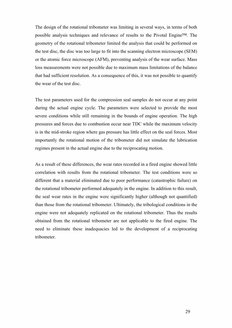
II.B. Mazda 13BT Rotary Seal Design (Wankel engine). The compression seals in the Mazda rotary engines do not operate in a reciprocating
motion like the seals in the Pivotal Engine™. However the seal arrangements between
the two engine designs are similar. Both the 13BT and Pivotal Engine™ must be able
to form a gas tight seal in a 90° corner, for this reason the design and materials used in
the successful Mazda system were investigated.
The seals in a Wankel engine (shown in Figure 7) have the same functionality and
requirements as piston rings in a conventional engine. However, a different approach
was taken with the selection of seal and chamber materials in the Mazda 13B series of
engines. The apex seal is made of electron beam chilled cast iron, which runs on a
porous chromium plated steel insert that is cast into the aluminium rotor housing. The
side and corner seals are manufactured from a soft iron and these seals run on a
nitrided cast iron surface [5]. So, in effect, the apex seal system has two relatively
hard materials in contact while the side and corner seal system have soft seals in
contact with a hard surface. This is in contrast to most piston engines which utilise
relatively hard piston rings on soft cylinder liners.
The side seals in the 13BT engine are not designed to form hydrodynamic oil films
between themselves and the side plates. The side seal has a thickness of 0.686mm, a
height of 3.15mm and a clearance of 0.028mm with the side seal groove, which are
similar to the dimensions of oil control rings in a four stroke piston engine. The small
clearance between the side seal and the rotor prevents combustion pressure from
acting on the back of the seal, allowing the contact force to be controlled solely by the
wave spring behind the seal. This arrangement allows the seal to still operate
satisfactorily with over 0.3mm of wear (limited by the loss of force applied from the
spring), significantly more wear than can be tolerated by a piston ring.
Like the side seal, the apex seal has a tight fit into the rotor with a nominal clearance
of 0.054mm. Because of the motion of the rotor, the apex seal profile is self
regenerating accommodating up to 1.5mm of wear. This sealing arrangement is
shown in Figure 7. The corner seal in the rotor is the junction point between the two
side seals and apex seal. The corner seal has a rubber insert to dampen the vibrations
of the apex seal, which can cause ‘chatter’ marks on the rotor housings.

19
The 13BT has a similar total loss lubrication system to most two-cycle engines, an oil
metering pump injects a small amount of oil onto the trochoid surface to provide
lubrication to the apex, corner and side seals. Although the rotational motion of the
Wankel engine should allow the formation of hydrodynamic lubrication between the
apex seal and the trochoid surface the high temperatures in the combustion process
tend to burn the oil off the trochoid surface, in this way the conditions encountered by
the seals in a Wankel engine are more severe than most piston engines.
Figure 7. Mazda 13B bridge port turbo engine, showing seal arrangement .
The most common failure mode of the seals in the Mazda 13BT is abrasive wear,
while premature failures are typically due to detonation causing the apex seals to
fracture. Detonation is generally caused by fuel or ignition problems on turbo charged
engines. The early Mazda Wankel engines have a reputation for being unreliable, a
reputation gained when the apex seals were manufactured from a carbon compound
and wore very quickly.

20
II.C. Non-Metallic Seal Materials. The straight seals in the Pivotal Engine™ mean that non-traditional piston ring
materials can be considered, notably ceramics. Ceramics are generally not suitable for
use as piston rings because of the ring dynamics, and the elastic deformation required
to produce a gas tight seal. The compression seals in the Pivotal Engine™ do not
require elastic deformation to provide a normal force (required for sealing), this force
is provided through the use of springs. The straight seals also mean that thin film
coatings can be easily applied without specialised tooling. Presently, thin film
coatings are applied to piston rings for specialised applications such as motor racing,
but are not common in mass produced engines.
II.C.1. Ceramic Tribology. A significant body of research has been carried out in the field of un-lubricated wear
of ceramics for use in internal combustion engines, most concerned with the
development of low heat rejection or adiabatic engines. The elevated operating
temperatures of these engines make the use of conventional lubricants impossible. It
is now generally accepted that ceramics do not offer sufficient wear resistance to be
used without lubrication [6].
A sizeable portion of research published on the lubricated wear of ceramics is
concerned with silicon nitride. This material has the potential to be used in
engineering applications that have traditionally used metals, because of its relatively
high fracture toughness (see Table 1) and better wear resistance than most metals.
Winn, Dowson and Bell [7, 8] conducted long term lubricated tri-pin-on-disc type
experiments using silicon nitride, alumina and 52100 steel pins against 52100 steel
discs under various speed and loading conditions. In addition, the wear response of
two types of oil was investigated, a refined mineral oil and an ester oil. Both base oils
have the same ZDDP and detergent additives.
The alumina pins performed poorly due to chipping of the wear surface, while the
52100 and silicon nitride pins had relatively low long term wear rates in the mineral
oil, 5 x 10-11 mm3N-1m-1 and 1 x10-11 mm3N-1m-1 respectively. The steel pins had a
high initial wear rate that decreased during the test, whereas the wear rate of the

21
silicon nitride pins increased proportionally with the increase in contact area. This
indicates tribochemical wear, in contrast to the abrasive wear experienced by the
52100 pins.
When the silicon nitride pins were tested in the ester oil, the initial wear rates were
approximately five times higher than those recorded in the mineral oil. As the test
conditions became less severe (lower contact pressure due to a larger contact area),
the ester based oil provided better protection than the mineral oil.
An important aspect of these experiments is the lack of evidence of the formation of a
protective film on the silicon nitride pins or the 52100 disc. Oil additives such as
ZDDP are reactive on ferrous surfaces, especially in tribological contacts where the
oxide surface layers are removed. These types of additives reduce wear by forming
protective/sacrificial films on the contact surfaces. This work, conducted by Winn et
al. indicates that ZDDP additives are of little or no use in the lubrication of ceramics.
Silicon nitride components can be manufactured in a number of ways resulting in
different material properties. Properties of sintered and reaction bonded materials are
compared in Table 1.
Table 1 Silicon nitride properties [9] Compressive strength Hardness Fracture toughness
Sintered 2000 MPa 1500 Hv 8 MPa1/2
Reaction bonded 550 MPa 1100 Hv 3 MPa1/2
Silicon nitride is now being used in production engines for components such as cam
followers and other components with high contact stresses. Nevertheless it would be
problematic to use silicon nitride as a piston ring material. It is likely that the
deformation required to install a silicon nitride ring on a conventional piston would
cause the ring to fracture. The use of silicon nitride for piston rings would require a
complete redesign of the piston and piston ring system, and compromises in the
design may outweigh any benefits. However, silicon nitride seals have the potential to
perform better than metallic seals where seal deformation is not a required
characteristic of the sealing system. This has been demonstrated by the successful use
of silicon nitride apex seals in Mazda’s 1992 Le Mans winning 787B. It was reported

22
by Shimizu, R., et al. [10] that when the engine was torn down after the race there was
minimal wear on the apex seals or the trochoid surface. A result of this is that silicon
nitride apex seals are now readily available for use in the 13B engines. The only
aspect preventing the widespread use of silicon nitride in this type of application is
cost (a set of six seals costing approximately $2000 NZD).
II.C.2. Thin Film Tribology. Thin films allow the surface properties of a component to be optimised for a specific
application while maintaining the bulk material properties. This has two significant
consequences. First, the usefulness of a component can be increased dramatically
without having to resort to a bulk material that may have other less desirable
properties or an increase in expense. Secondly, the bulk material and the thin film
properties can be optimised independently of each other, typically not possible with
most materials.
Thin films are deposited onto a surface using one of two methods (or variations of
these), chemical or physical vapour deposition (CVD and PVD respectively). For the
application of thin films onto piston rings, the PVD process is the more appropriate
method due to the lower deposition temperatures, 50°C to 500°C compared to 800+°C
for CVD processes. High temperatures can cause the long slender section of a piston
ring to warp, leaving it unusable after the coating process.
Desirable mechanical properties of a thin film for piston ring applications include a
high hardness to minimise abrasive wear and adequate adhesion with the substrate. To
meet these requirements, films such as titanium nitride (TiN), chromium nitride (CrN),
tungsten-carbide carbon (WC-C) and diamond like carbon (DLC) are employed.
One limitation to the use of thin films on piston rings is the maximum thickness that
the film can be grown to, restricting the life of the film in a wear environment. The
internal stresses of the film increase as a function of the coating thickness, thus
limiting thickness is reached when the internal stress is high enough to cause the film
to fail without any external influence. This problem can be overcome by depositing
discrete functional layers. For example, TiN has a maximum film thickness of
approximately 5µm before the film will fail. Yet it is relatively easy to deposit a TiN

23
layer followed by a Ti layer (by eliminating the nitrogen gas flow in the process
chamber). This system can be repeated many times until a coating of the required
thickness is achieved. For example, Lyubimov et al. [11] developed and tested two
multi layer titanium-titanium nitride coatings for use on piston rings. The first coating
system utilised four layers. The first 0.5µm thick titanium layer is a conformal
interface between the cast iron ring material and the subsequent 3µm titanium nitride
layer. These two layers are followed by a 1µm titanium layer and a 3µm titanium
nitride layer. The intermediate titanium layer is a buffer between the hard TiN layers,
reducing internal stresses in the titanium nitride layers while preventing crack
propagation through the coating system.
The second coating consisted of 5 layers, being the same as the four layer coating
with the addition of a 2µm titanium layer on the outermost titanium nitride layer. The
purpose of this layer is to accelerate the running-in of the engine, by removing
asperities and high points on the cylinder liner. Accelerating the break-in period
allows loads to be distributed evenly over the ring surface earlier, which in turn
reduces the wear that is experienced by the ring and cylinder liner system. Lyubimov
et al. showed that when tested in a two-cycle scooter (Muaravey) the five layer
titanium-titanium nitride PVD coating increased the piston ring life by 3 times
compared to an uncoated ring, and 1.7 times compared to an electroplated chromium
ring.
In addition to the mechanical properties attainable through the use of PVD coatings,
the manufacturing process is considerably more environmentally friendly than
electroplating processes. The only waste products released from the PVD process are
nitrogen and argon (and methane for DLC coatings). Electroplating processes employ
large volumes of toxic chemicals that need to be replaced periodically and therefore
disposed of.

24
II.D. Tribological Testing. Testing of wear and friction properties of materials can be conducted on several
different levels with respect to the final application. Holmberg [12] divided
tribological tests into six levels as shown in Figure 8. Essentially, the closer the test
conditions are to the intended environment the more relevant the test results. However,
the repeatability and statistical significance decrease. Whittaker and Matthews [13]
reported that laboratory wear tests generally help eliminate poorly performing
materials, but it is unlikely that these tests will be able to identify an optimum
material combination for a specific application.
For the example of piston rings, simple tests could be conducted with a pin
manufactured from the piston ring material and tested in a standard pin on disc
tribometer against a hardened steel disc. This test will provide some data on the wear
rate of the ring material, but it is not likely to be indicative of the performance of the
piston ring material in an actual engine due to the significant difference in
environmental conditions. For these reasons, most tribological testing of the piston
ring cylinder liner system is conducted with a combination of miniature, component,
rig and field tests.
Figure 8. the six levels of simulation in tribological testing [13].

25
Various tests have been implemented for analysis of the piston, piston ring pack and
cylinder liner system of the internal combustion engine. In this system, research is
generally conducted in friction and wear of the piston ring-cylinder liner system
and/or investigation of oil films formed between the piston ring and the cylinder liner.
These tests can be classified into three groups: (1) fired engine tests, (2) motored
engine tests and (3) tribometer tests. In regard to Holmberg’s six levels of simulation,
a fired engine test could be considered either a field test or a rig test, a motored engine
would be a component test and a tribometer test could be a miniature test, a contact
simulation test or a simple sample test depending on the type of tribometer used.
II.D.1. Fired Engine Tests. Ma et al. [14] studied the break-in liner wear and piston ring assembly friction in a
spark ignited engine (fired engine test). A surface layer activation method was used to
measure the wear of the liner. Friction forces were calculated by relating engine
pressures (combustion and crankcase) to the measured torque (IMEP method). During
the test the engine load was controlled by a dynamometer. The engine speed and load
were increased through the test to simulate a driving cycle. Ma et al. reported that the
friction and wear measurements had no direct correlation to each other, although the
surface roughness and friction showed a linear relationship.
In addition to instrumented and controlled experiments as outlined above, it is
common for studies of piston ring-cylinder liner wear and oil consumption to be
carried out in engines on test beds under simulated driving conditions and fleet tests.
These tests are frequently used to validate model tests or theoretical analysis.
II.D.2. Motored Engine Tests. Motored tests are simpler than fired engine tests. Without combustion it is much
easier to control selected variables and, as a consequence of this, results are more
easily interpreted although not as representative. For example, Cho, Choi and Bae [4]
investigated the frictional modes of a barrel shaped piston ring under fully flooded
conditions by measuring friction using a floating liner in a motored engine. These data
were then used to produce modified Stribeck diagrams (Figure 6) for the lubrication
regimes present near the dead centres and in the mid-stroke of the engine. The
Stribeck diagram plots the friction coefficient against the bearing parameter µωp-1,

26
were µ is the lubricant viscosity, ω is rotational velocity and p is the applied load. The
Stribeck diagram can then be used to predict whether the piston rings are operating in
a boundary, mixed or hydrodynamic lubrication regime from measured coefficients of
friction with the assumption of fully flooded inlet conditions.
II.D.3. Tribometer Tests. Most experiments that are concerned with the wear rates and friction of piston ring-
cylinder liner systems have been conducted on reciprocating tribometers. Hill,
Hartfield-Wunsch and Tung [15] tested three common cylinder bore materials (cast
iron, Nikasil and 390 Al) against three piston ring materials (chromium plated cast
iron, molybdenum coated cast iron and gas nitrided stainless steel) using a modified
Cameron Plint (C-P) tribometer and an Electro-Mechanical LS9 tribometer. The C-P
tribometer was operated with a load of 80N, 10mm stroke at 10Hz for 40 hours at
120ºC while the LS9 tribometer was operated with a load of 72N, 25mm stroke at
8.5Hz for 30 hours at 165ºC. The wear of the piston rings on the C-P tribometer was
quantified using a mass loss technique while bore wear was measured from a surface
trace. Both the bore and ring wear from the LS9 tribometer was measured using a
profile trace. The lowest combined wear was with gas nitrided stainless steel rings on
cast iron liners. Hill et al. also found that the results from the LS9 and C-P tribometers
did not concur since the 390 Al had much higher wear rates on the LS9 tribometer. It
was hypothesised that this was due to the 390 Al being more sensitive to oil and
temperature than the Nikasil and cast iron bore materials.
Akalin and Newaz [16, 17] developed an analytical model to calculate friction force
for the ring-liner contact in a mixed lubrication regime. Their model implemented a
modified Reynolds equation, which included surface roughness and flow factors as
well as a statistical representation of the surface asperities. To verify this model, a
reciprocating test system was designed and built with a stroke of 84mm, maximum
speed of 750rpm, maximum ring contact force of 360N and a maximum temperature
of 100ºC. Their results showed that running speed, temperature and surface roughness
were important parameters for defining the lubrication regime. They also found that
the normal applied load only had a minor affect in the friction force in the mixed
lubrication regime. Their model was a good representation of the results obtained
from the test system.

27
II.E. Wear Measurement. A challenge in the field of tribology is the interpretation and application of published
wear rates. This is a problem because there is no specified quantity for describing the
wear rate of a material or system and different wear rate measurements cannot always
be converted to a more useful measure. Some measures of wear described by
Ravikiran [18] include:
Wear V m3
Wear rate W m3m-1
Specific wear rate Wsp m3N-1m-1
Wear coefficient K Dimensionless
Normalised wear rate Wn Dimensionless
Of these measures, the wear rate W is most commonly used, being the volume loss
per unit sliding distance. The specific wear rate Wsp is the wear rate normalised to the
applied normal load and is also a commonly used measure. The wear coefficient K is
Wsp multiplied by the room temperature hardness and Wn is W divided by the contact
area. In addition to the above measures, in some instances wear is reported as a linear
measurement or a mass loss.
In all cases (shown above), wear contains a volume term. In most cases the worn
volume is calculated using the mass loss of the worn component in conjunction with
the material density or by measuring the change in worn and unworn surface profiles
relative to a known datum.

28
III. Procedure.
III.A. Equipment.
III.A.1. Rotational Tribometer. The bulk of the testing was carried out on a rotational tribometer. This tribometer had
been designed and built as part of an undergraduate course at the University of
Canterbury. The tribometer rotates a 200mm diameter disc at 2850rpm, equating to a
relative velocity of 27ms-1 between the seal sample and the disc surface. This is
equivalent to the instantaneous velocity of the front compression seal in the engine at
mid-stroke when running at 5000 rpm. The force applied to the seal sample was
calculated from the combustion pressure acting on the back surface of the
compression seal, shown schematically in Figure 3. Based on a combustion pressure
of 5.65 MPa, for a 15mm x 1.24mm seal sample the force was calculated to be 105N.
This value does not take into account the load applied by the wave spring, which is
unknown (not shown in Figure 3) or any centripetal forces.
To increase the usefulness of the rotational tribometer, strain gauges were added to
the vertical support. Allowing measurements of the friction between the seal and disc,
which are then periodically logged to a data file. The software used to log the friction
data also controls the oil delivery rate, utilising a plunger type metering device. Oil is
delivered as a mist that is forced onto the disc surface by compressed air. The
modified rotational tribometer is shown in Figure 9.
Figure 9 Rotational tribometer.
29
The design of the rotational tribometer was limiting in several ways, in terms of both
possible analysis techniques and relevance of results to the Pivotal Engine™. The
geometry of the rotational tribometer limited the analysis that could be performed on
the test disc, the disc was too large to fit into the scanning electron microscope (SEM)
or the atomic force microscope (AFM), preventing analysis of the wear surface. Mass
loss measurements were not possible due to maximum mass limitations of the balance
that had sufficient resolution. As a consequence of this, it was not possible to quantify
the wear of the test disc.
The test parameters used for the compression seal samples do not occur at any point
during the actual engine cycle. The parameters were selected to provide the most
severe conditions while still remaining in the bounds of engine operation. The high
pressures and forces due to combustion occur near TDC while the maximum velocity
is in the mid-stroke region where gas pressure has little effect on the seal forces. Most
importantly the rotational motion of the tribometer did not simulate the lubrication
regimes present in the actual engine due to the reciprocating motion.
As a result of these differences, the wear rates recorded in a fired engine showed little
correlation with results from the rotational tribometer. The test conditions were so
different that a material eliminated due to poor performance (catastrophic failure) on
the rotational tribometer performed adequately in the engine. In addition to this result,
the seal wear rates in the engine were significantly higher (although not quantified)
than those from the rotational tribometer. Ultimately, the tribological conditions in the
engine were not adequately replicated on the rotational tribometer. Thus the results
obtained from the rotational tribometer are not applicable to the fired engine. The
need to eliminate these inadequacies led to the development of a reciprocating
tribometer.

30
III.A.2. Reciprocating Tribometer. To overcome the limitations of the current tribometer and better simulate the
environmental conditions encountered in the engine, a completely new tribometer was
designed. The reciprocating tribometer is shown in Figure 10 (with the safety guard
removed for clarity) and the operating parameters of the reciprocating tribometer are
summarised in Table 2. A complete parts list is shown in Table 3. The two most
important design specifications were that the relative motion between the seal sample
and the test block should be reciprocating and that the test block should be small
enough to fit into an SEM for analysis of the wear surface. In addition to these
requirements, considerations were made for the ability to heat the test block and to
measure lubricating oil film thickness measurements via an electrical resistance
method. Because of time and cost considerations, these features were not
implemented (but could be in the future).
Table 2 Reciprocating tribometer operational parameters. Reciprocating Tribometer Specifications
Operating speed 400 rpm to 1400 rpm
Contact force 50N minimum 250N maximum
Lubrication Continual Drip Feed or Fixed Volume
Bath
Friction force measurement range ± 100N
Data acquisition USB 1000Hz
Seal sample dimensions (T x L x H) 1.24 – 2.50 x 15.00 x 3.0 – 5.00 mm
Test block nominal size (W x L x H) 30mm x 90mm x 15mm
Motor power 0.275 kW
Tribometer mass 55 kg

31
Figure 10 Reciprocating tribometer.
Two methods for achieving a reciprocating motion were considered: (1) a linear
reciprocating motion such as that of a piston in a conventional engine or (2) a
rotational reciprocating motion. The latter was chosen as it negates the need for
expensive linear bearings and better simulates the motion of the piston in the Pivotal
Engine™.
An important design consideration is the ability to balance the tribometer. To achieve
this, two test stations are driven off a common crank shaft with a 180˚ phase offset.
Because the vertical crank shaft has two journals at 180˚, the centre of mass of each
test station is on a different horizontal plane, inducing a moment. The use of offset
connecting rods allows the horizontal planes of the test stations to be as close as
possible, minimising any dynamic balance problems. Because the connecting rods are
offset they will experience a bending moment. For this reason the connecting rods
feature triangulated webbing to maximise strength while maintaining a low mass, the
connecting rod is shown in Figure 11. The webbing on the bottom of the connecting
rod is opposite that on the top to further increase strength. The surface at the bottom
of the webbing (highlighted green in Figure 11) is 2mm thick and horizontal for the
length of the connecting rod. A larger offset could have been used if this surface was
not horizontal but that would have complicated the manufacture of the connecting rod.

32
The connecting rods were manufactured from 7075 T6 aluminium. This material was
chosen as it has a reasonably high strength to weight ratio as well as being easy to
machine. All of the components which are not mass sensitive are manufactured from
1020 steel as this is a cheap material that is easy to machine.
Figure 11 Offset connecting rod with triangulated webbing, the horizontal surface is highlighted
in green. Figure 12 shows an image of the crankshaft at BDC with both connecting rods fitted.
The offset connecting rods mean that the centre web in the crankshaft has to be cut
down to provide sufficient clearance for the connecting rods to pass. To ensure
sufficient rigidity of the crank assembly the crank pins are pressed into the centre web
and then welded on the back side. Welding the back side of the crank pins is required
for the centre web because of the relatively small contact area between the crank pins
and the web. This assembly is shown in Figure 13. The crank pins extend through the
full thickness of the top and bottom crank halves so welding is not required. Not
welding the outer ends of the crank pins means that the axial clearance of the big end
bearing can be adjusted by pressing the crank apart and changing the thrust washers.
Separate thrust washers were used so further simplify the manufacture of the crank
webs (as opposed to having raised bearing surfaces on each web). The crankshaft has
a throw of 40mm, which moves the seal holder through an arc of 40°. The maximum
force in the tribometer occurs at the crankshaft end of the connecting rod, where a
maximum force of 1597N is experienced at a crankshaft speed of 4000rpm. At the
anticipated operating speed of 1000rpm, this force drops to 100N. Both of these
forces will be safe for material strength and bearing life.

33
Figure 12. Tribometer crankshaft with offset connecting rods.
Figure 13. Crankshaft center web with crank pins welded in place.
The arm in which the seal sample is mounted (seal holder in Figure 14) is also
manufactured from 7075 T6 aluminium in an effort to minimise reciprocating mass.
The bearings in the seal holder assembly have a running fit on the main pivot to allow
the application of a vertical load to be applied through the inner shell of the top taper
roller bearing (the load path is shown in Figure 15). The applied load will prevent the
inner race of the bearings spinning on the main pivot. It is for this reason that there is
a minimum required applied load of 50N. The gudgeon pin has a light press fit into
the seal holder and is retained by the gudgeon pin cap, which also has a light press fit
on the gudgeon pin. To allow the disassembly of the connecting rod and seal holder

34
the gudgeon pin cap is drilled and tapped in the centre so a bolt can be threaded in to
lift the cap off the gudgeon pin. The gudgeon pin has a 6mm hole drilled through its
centre which can be filled with grease. A 6mm pin can be pressed into the hole
forcing the gudgeon pin out of the seal holder to disassemble the connecting rod from
the seal holder. Although clumsy, this procedure is required for the initial setup of the
tribometer and is the only part of the tribometer that requires disassembly.
The chamber coating is applied to a 30mm x 90mm x 15mm aluminium block, the test
block is held in a floating fixture with the tangential friction force constrained and
measured with a load cell. Radial forces are constrained using a deep groove ball
bearing on a common axis with the seal holder. The test block holder bears on an
adjustable plate to allow for variances in the combined seal and test block height and
flatness. Figure 14 shows an exploded view of one test station and the crankshaft (It is
the levelling of this plate that requires the seal holder to be disconnected from the
connecting rod).
To level the base plate, the test block and seal sample are first fitted to the tribometer.
The base plate is then adjusted so that, with the combined height of the seal sample
and test block, the connecting rod is not being forced up or down. At this stage, the
seal holder and connecting rod are disconnected to allow room for a dial gauge and
magnetic base to be moved around the base plate. The dial gauge is used to set the
base plate to horizontal (or parallel relative to the main base plate), by adjusting the
eight socket head cap screws on the corners of the base plate. The inner cap screws
pass through the base plate and are threaded into the main base plate, while the outer
cap screws are threaded into the base plate and bear against the main base plate. This
allows the height and angle of the base plate to be adjusted independently.
The tribometer is built on a 20mm thick steel base, which is mounted on a fabricated
steel frame using rubber mounts, providing rigidity as well as mass to dampen
vibrations. To allow the speed of the tribometer to be controlled a 0.275 kW three
phase electric motor is used in conjunction with an inverter. Power is transmitted from
the motor to the crank shaft through an A section V-belt drive. The use of the V-belt
drive will allow the tribometer speed range to be easily changed at a later date.

35
To ensure the safety of the tribometer operators an enclosure was constructed to
completely cover the tribometer. In addition to operator safety, the enclosure also
helps prevent contamination of the wear system by foreign bodies that could affect the
measured wear rates.
One major deviation of the reciprocating tribometer from the actual engine is that, on
the tribometer, the seal sample is rigidly clamped while in the engine there is a
clearance between the seal and the piston to allow gas pressure to act on the back of
the seal. This was not considered to be a significant compromise since analysis of
worn seals from the engine revealed the wear surface is almost perfectly flat,
indicating that the seal does not move in the seal groove.
The addition of combustion products and un-burnt fuel in the engine will affect the
wear rates of the material couples, however to incorporate these aspects into the
tribometer would troublesome. The addition of fuel would require the tribometer to be
located in a fume hood or similar, and would create a significant fire risk due to the
elevated temperatures. When testing piston rings for four-cycle engines, [19] more
realistic results are obtained when testing is performed with used lubricating oil,
contaminated with wear particles, fuel and combustion by-products. The nature of a
two-cycle engine means that used/contaminated oil is replaced by clean oil, thus
removing contaminants from the contact area. For this reason the drip feed system
was deemed suitable, with used oil draining from the bottom of the tray. It is also
possible to run a test with a fixed volume of oil around the test block by blocking the
drain tube. The drip feed system can be seen in Figure 10. Oil is delivered through
silicone tubes which are supported by copper tubes. The flexible silicone tube allows
the oil delivery point to be very close or even in contact with the seal holder, ensuring
that the oil is delivered to the contact zone.

36
Table 3 Parts list for reciprocating tribometer Component Material Quantity
1 Frame 1020 1
2 Rubber mounts N/A 4
3 Main base Plate 1020 1
4 Motor frame 1020 1
5 Motor N/A 1
6 Motor pulley A-section 110mm CI 1
7 Crank pulley A-section 90mm CI 1
8 Crank bottom 1020 1
9 Crank pin 1020 2
10 Crank web 1020 1
11 Crank thrust washer 1020 4
12 Main bearing 6006 deep groove ball N/A 2
13 Big end bearing NA4902 needle roller N/A 2
14 Housing base 1020 1
15 Housing end 1020 2
16 Housing top 1020 1
17 Bearing retainer 1020 1
18 Top brace 1020 1
19 Top brace spacer 1020 1
20 Connecting rod 7075 T6 2
21 Small end Bearing NA4901 needle roller N/A 2
22 Small end thrust washers 1020 4
23 Gudgeon pin 1020 2
24 Seal holder 7075 T6 2
25 Seal clamp 7075 T6 2
26 Gudgeon pin cap 7075 T6 2
27 Seal holder top bearing 30302 taper roller N/A 2
28 Seal holder bottom bearing 6302 deep groove ball N/A 2
29 Main pivot shaft 1020 2
30 Oil tray 1020 2
31 Sample carrier 7075 T6 2
32 Sample carrier main bearing 6202 deep groove ball N/A 2
33 Sample carrier end bearing 626 deep groove ball N/A 4
34 Load cell 7075 T6 2
35 Sample carrier spacer 1020 2
36 base plate 1020 2
37 Upright 1020 2
38 Upright cap Al bar stock 2
39 Load arm A 1020 2
40 Load arm B 1020 2
41 Load collar Al bar stock 2
42 A 38 V-belt N/A 1
43 M10 x 40mm SHCS N/A 4
44 M8 x 35mm SHCS N/A 12
45 M6 x 35mm SHCS N/A 26
46 Oil drip feed N/A 1

37
Figure 14 Exploded view of test station and crank of reciprocating tribometer.
Figure 15. Reciprocating tribometer indicating the load path.

38
III.A.3. Other Equipment. A Taylor-Hobson ‘Tally surf’ surface profile measurement system was used to
measure Ra values of the chamber coatings as well as the actual surface profiles of the
worn coatings. Optical images were taken using a Leica DM IRM inverted research
microscope in with a Zeiss Axiocam digital camera. The images used to quantify seal
wear rates were taken in dark field mode while most of the optical images used to
examine microstructures used differential interference contrast. The use of differential
interference contrast also allowed high magnification images to be taken of wear
surfaces. Finally a JEOL JSM 6100 scanning electron microscope fitted with an
Oxford eXL energy dispersive X-ray analyser system was used to take high
magnification images of wear surfaces and produce EDS maps and spectra of some of
the tested materials.

39
III.B. Material Test Procedure. Material test procedures were implemented to standardise the experimental procedure
and ensure repeatability. A range of test procedures were developed to accommodate
the large differences in system wear rates as well as the two different tribometers.
III.B.1. Rotational Tribometer Test Procedure. The first test procedure was developed for material combinations that gave wear rates
that could be measured using mass loss techniques.
Four-hour Rotational Test Procedure.
1. Seal cut, de-burred, cleaned and weighed
2. Test disc dressed (600 grit wet and dry sandpaper) and cleaned
3. Surface roughness values of test disc measured (Ra)
4. Strain gauges on test rig calibrated using dead weights
5. Test run
• continual lubrication, Morris race 2 oil
• seal normal load of 105N
• rotational speed of 2850 rpm
• four hour test duration
6. Seal cleaned and weighed
7. Wear rate determined
8. Seal cut and mounted
9. Optical images taken of seal
10. Surface roughness values of test disc measured (Ra)
11. Test data entered into data base
This procedure was repeated three times for each seal – disc combination, using a new
seal sample for each test. Step 2 was only applied to the first of the three tests to
remove any surface damage from previous tests, and to give a consistent initial
surface. The test duration of four hours was chosen arbitrarily, but provided sufficient
seal wear to allow accurate mass loss measurements. Steps 8 and 9 provided little
information so were omitted from most of the tests. Initially steps 3 and 10 were

40
implemented but because the Ra values were constant (0.54µm Ra) between different
discs (before and after testing) this was deemed unnecessary for further tests.
A second, more severe procedure was implemented. This procedure was intended to
simulate a starved lubrication condition, which may be present in the engine (little is
known about the distribution of oil in the engine). This procedure was the same as
above, except that there was no continual lubrication over the duration of the test. The
disc had a layer of oil applied over the surface before the start of the test, and the test
was then run for twenty minutes instead of the four hours of the first procedure.
Twenty-minute Starved Lubrication Rotational Test Procedure.
1. Seal cut, de-burred, cleaned and weighed
2. Test disc dressed (600 grit wet and dry sandpaper) and cleaned
3. Strain gauges on test rig calibrated using dead weights
4. Test run
• initial lubrication, Morris race 2 oil
• seal normal load of 105N
• rotational speed of 2850 rpm
• twenty minute test duration
5. Seal cleaned and weighed
6. Wear rate determined
7. Seal cut and mounted
8. Optical images taken of seal
9. Test data entered into data base
The testing of the arc seal samples involves the same procedure as the four-hour test,
with the addition of a setup procedure prior to the start of the test. Because of the
geometry of the arc seal, a different seal clamp is used. The setup procedure requires
the seal clamp be adjusted so that the seal sample sits flat against the test disc. It is
also necessary to clamp the weight arm to prevent the seal from tilting during the test.
In both of these rotational test procedures, the seal wear rates were determined by the
total mass loss over the course of the test. It was originally intended that the disc
coating wear would be measured using a Taylor-Hobson ‘Tally surf’ surface profile
measurement system, however the surface topography was dominated by porosity

41
from the coating application process. If the test disc had been smaller, it would have
been possible to quantify wear using mass loss or atomic force microscopy. Finally,
the only way to assess the wear of the coating was to subjectively rank the discs based
on the appearance of the surface. Even with this method, it was only possible to
identify coatings that performed very badly.
III.B.2. Rotational Tribometer Test Procedure for Low Wear Material Systems. A third test method was required because some of the compression seal materials had
wear rates that were so low no mass loss (less than 0.0001 gm) could be measured
over extended periods on the tribometer.
Extended Rotational Test Procedure.
1. Seal cut, de-burred, cleaned and weighed
2. Test disc dressed (600 grit wet and dry sandpaper) and cleaned
3. Strain gauges on test rig calibrated using dead weights
4. Test run
• continual lubrication, Morris race 2 oil
• seal normal load of 105N
• rotational speed of 2850 rpm
• test run for six to nine hours
5. Seal cleaned and optical images taken
6. Seal remounted in tribometer and test restarted
After a period of time (between six and nine hours) the seal sample was removed
from the tribometer, cleaned in acetone and mounted in a clamp. A second used seal
sample was permanently mounted in the clamp for reference measurements. Images
were taken along the length of the wear surface the reference seal using a Leica DM
IRM inverted research microscope in dark field mode with a Zeiss digital camera. The
images were joined in Adobe Photoshop to form a montage image of the seal surface,
which was then cropped to contain just the flat area of the seal surface. The reference
images were processed by adjusting threshold and contrast values until they had the
same black and white pixel count. The threshold and contrast values for each
reference image were then applied to the corresponding montage seal image. The
processing of a sample is shown graphically in Figure 16. The change in worn surface
area over a period of time is then used to compare wear resistance of the various seal

42
materials. It should be noted that even when 100% of the seal surface had been worn
there was still no measurable mass loss.
Figure 16 Seal wear surface image processing

43
III.B.3. Reciprocating Tribometer Test Procedure. A fourth test method was implemented for the reciprocating tribometer. Further
details of this procedure of the are given in section III.A.2.
Reciprocating Test Procedure.
1. Tribometer set up for each test block
2. Seal cut, de-burred, cleaned and weighed
3. Test block dressed (600 grit wet and dry sandpaper), cleaned and weighed
4. Test run
• continual lubrication, Morris race 2 oil (drip feed)
• seal normal load of 105N
• test frequency 21 Hz (1275 rpm)
• 40° arc at 105mm radius
• twenty hour test duration
5. Seal cleaned and weighed
6. Test block cleaned and weighed
7. Wear rates determined
8. Test data entered into data base

44
IV. Results and Discussion.
IV.A. Material Selection. Chamber and compression seal materials were selected for testing based on successful
use in environments similar to those expected in the Pivotal Engine™, notably
conventional two and four-cycle piston engines and the Mazda Wankel engine. In
addition to this criterion, component cost had a strong influence on the selection of
potential materials.
IV.A.1. Compression Seal Materials. The primary selection criterion for compression seals was high hardness. The
dominant compression seal wear mechanism is abrasive wear. Increasing the hardness
of the seal material will generally increase its resistance to abrasive wear. Other
parameters such as surface free energy have been shown to be related to system wear
[20] but were not expressly considered in this work. The materials selected for testing
are shown in Table 4.
IV.A.2. Chamber Materials. A range of common cylinder liner materials were rejected early in the material
selection process for various reasons. Cast iron, the most common cylinder liner
material, has graphite flakes that provide solid lubrication and act as reservoirs for
lubricant. However cast iron was not considered purely on the basis of mass. The
increase in mass associated with manufacturing the engine from cast iron instead of
aluminium is unacceptable. In addition to cast iron, all of the electroplated material
systems were eliminated. Electroplated materials were eliminated because of the high
costs involved in producing tooling that would promote an even deposition on the flat
surfaces of the engine components. This includes materials such as hard chromium
and Nikasil. These coating systems or variations of them are used in most motor bike
engines and some automotive engines. Nikasil consists of silicon carbide particles
(approximately 4µm in size) that are dispersed in a nickel matrix. The nickel acts as a
binder while the dispersed silicon carbide particles minimise the wear of the system.
Variations of this system are available with different binders and different ceramic
particles.

45
The elimination of these materials left thermal spray coatings as the only option.
Thermal sprayed coatings can be applied by a number of methods such as flame
spraying, arc spraying, detonation gun and plasma spraying. In most of these
processes, the deposited coating material is processed from a powder, although some
systems use wire. The properties of the applied coating depend on the composition of
the powder or wire in conjunction with deposition parameters such as power and
substrate temperature. If the coating is deposited from a powder, the coating structure
is also dependent on the original particle size. The chamber coating materials selected
for testing are shown in Table 4.
Table 4. Test Materials. Compression seal materials Chamber coatings Nitrided stainless steel (N-SS) Pivotal Engineering 75B-90MXC
Mazda 13BT Apex Seal (Cast Iron) Pivotal Engineering tungsten
Silicon nitride Sulzer Metco XPT512
Titanium nitride coated N-SS (TiN) Sulzer Metco F2056
Chromium nitride coated N-SS (CrN) Sulzer Metco F4301
Tungsten carbide carbon coated N-SS (WC-C) NASA PS304
Diamond like carbon coated N-SS (DLC)
Silicon nitride coated N-SS (SiN)
Plasma nitrided titanium

46
IV.B. Material Characterisation. The majority of materials selected for testing were proprietary. Because of this, there
was little or no information on the material properties. In this work, the material
microstructure and properties are important for two reasons. Firstly, some of the
chamber coatings were not applied by the company that developed and produces the
coating system. This means that the tested coating may not have the mechanical and
microstructual properties intended by the developer. Secondly it is necessary to know
what types of materials are being tested so results can be compared with other
research.
IV.B.1. Nitrided Stainless Steel. The composition of the stainless steel seal material is similar to AISI type 446
stainless steel. The EDS spectrum and composition is shown in Figure 17. The seal is
nitrided to provide a hard wear resistant surface (750Hv) while the bulk material is a
fine martensitic structure with a micro hardness of 400Hv. A cross section of the
nitrided stainless steel seal is shown in Figure 18 A and B. A nitrided layer can be
clearly seen in both images.
Figure 17. EDS spectrum of nitrided stainless steel seal.

47
Figure 18 differential interference contrast micrographs of nitrided stainless steel seal, showing
the nitrided layer.
A problem with stainless steel piston rings is that they are prone to micro welding to
the aluminium ring lands under certain conditions. This can be even more detrimental
to engine performance than piston ring wear. Some aluminium alloys are more
susceptible to micro welding than others, making it possible to lessen this problem
through material selection. Other solutions include surface treatments of both the ring
and ring groove, and most importantly ensuring that there is sufficient lubrication in
the piston ring groove.
IV.B.2. Mazda 13BT Apex Seal (Cast Iron). In terms of cost and performance, cast iron is still one of the best materials available
for the manufacture of piston rings. The graphite phase in cast iron provides limited
solid lubrication in the form of a graphite film, as well as acting as a lubricant
reservoir. This property helps prevent scuffing and high wear during periods of
interrupted lubrication. The only significant disadvantage of cast iron is that it
generally has low tensile strength and fracture toughness. The graphite phase acts as
pre-existing cracks. This requires piston rings be made thicker than may be desirable
to retain sufficient strength, which in turn increases the inertial loadings on the piston
ring lands.
Since there was not a readily available supply of straight cast iron piston ring material,
a Mazda 13B three piece apex seal was used for testing purposes (both rotational and
reciprocating tribometers require straight seal samples). The composition of the cast
iron is specific to this application. The EDS spectrum is shown in Figure 19.
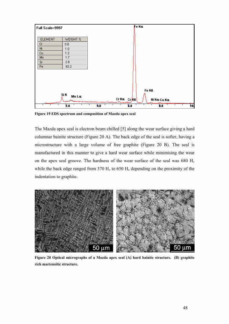
48
Figure 19 EDS spectrum and composition of Mazda apex seal
The Mazda apex seal is electron beam chilled [5] along the wear surface giving a hard
columnar bainite structure (Figure 20 A). The back edge of the seal is softer, having a
microstructure with a large volume of free graphite (Figure 20 B). The seal is
manufactured in this manner to give a hard wear surface while minimising the wear
on the apex seal groove. The hardness of the wear surface of the seal was 680 Hv
while the back edge ranged from 370 Hv to 650 Hv depending on the proximity of the
indentation to graphite.
Figure 20 Optical micrographs of a Mazda apex seal (A) hard bainite structure. (B) graphite
rich martensitic structure.
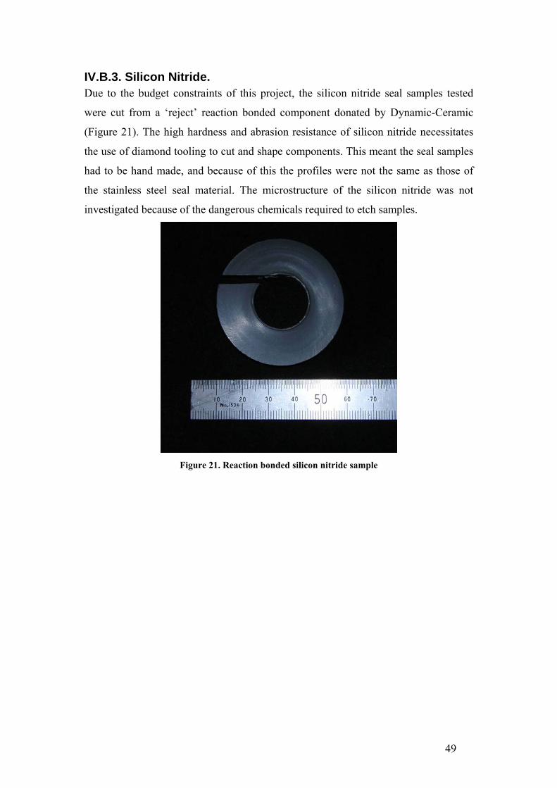
49
IV.B.3. Silicon Nitride. Due to the budget constraints of this project, the silicon nitride seal samples tested
were cut from a ‘reject’ reaction bonded component donated by Dynamic-Ceramic
(Figure 21). The high hardness and abrasion resistance of silicon nitride necessitates
the use of diamond tooling to cut and shape components. This meant the seal samples
had to be hand made, and because of this the profiles were not the same as those of
the stainless steel seal material. The microstructure of the silicon nitride was not
investigated because of the dangerous chemicals required to etch samples.
Figure 21. Reaction bonded silicon nitride sample

50
IV.B.4. Titanium Nitride Coated N-SS. Titanium nitride was selected as a potential material due to its high hardness and
reasonably good toughness, both of these properties being favourable in minimising
abrasive wear. TiN can have hardness values of up to 2300 Hv and film thickness of
up to 5µm (limited by internal stress).
TiN is deposited in one of two ways using the PVD process. A TiN target can be used
in an argon atmosphere or a Ti target can be used in a nitrogen and argon atmosphere.
The latter is the more common method and is known as reactive sputtering. In this
process, the nitrogen in the chamber reacts with the Ti atoms deposited on the
substrate surface to form TiN. The film properties are dependent on the substrate
temperature, DC current bias, power and the nitrogen concentration. These variables
control the amount of nitrogen in the film from TiN<0.8 to TiN>1.2 as well as the
favoured crystallographic growth direction, either <111> or <200> directions normal
to the film surface.
Because of the costs involved in acquiring a commercial titanium nitride coated
sample, the Electrical Engineering department’s magnetron sputtering (PVD) machine
was used to deposit a TiN film on a nitrided stainless steel sample. The seal samples
were cleaned in petroleum spirits followed by acetone to remove any oils on the seal
material. Once mounted in the sputtering machine and a sufficient vacuum reached,
the substrate was sputter etched in a high argon flow rate to remove any surface
contaminants. A titanium film was deposited to act as a conformal interface between
the nitrided stainless steel and the TiN film. For this layer, an argon flow rate of 9.97
sccm (standard cubic centre metre per minute) was used in conjunction with a power
of 300W and a temperature of 57°. Sputtering commenced for 16 minutes using a
titanium target of 99.999% purity, producing a film approximately 0.8 µm thick. The
TiN layer had the same deposition parameters as the Ti layer with the addition of
nitrogen at a flow rate of 2.23 sccm. The machine was run for 57 minutes, producing
a film thickness of 1.7 µm. These flow rates were used as they are known to work in
this particular machine (the gas flow rates affect the plasma stability), not for the
specific properties that they would produce. It is likely that these deposition
parameters favoured the formation of a TiN>1.2 film, having a much lower hardness
than the desired TiN0.9-1 film. The composition of the film is indicated by the brown-

51
black colour as opposed to the desirable gold colour [21]. A higher nitrogen flow rate
would have given a film with better properties for this application but would have
slowed the deposition rate (assuming plasma stability was maintained). Figure 22
shows a cross section of the seal sample with the titanium and titanium nitride layers.
The electroless nickel coating was applied to retain the integrity of the Ti/TiN film
during the sectioning and polishing process.
Figure 22 A optical micrograph of a layered Ti/TiN film on N-SS. The nickel layer was applied to
aid in metallographic preparation.
Due to the small thickness of the film it is not possible to measure an accurate
hardness value without influence from the substrate material (with the available
equipment). To avoid the influence of substrate properties the criterion of h < 0.1d
must be met, where h is the indentation depth and d is the film thickness [22]. It is
likely that the hardness of this TiN film is around 800 Hv (estimated from the film
colour), which is not significantly harder than the nitrided layer on the stainless steel
seal (750 Hv) and subsequently not expected to provide a significant change in wear
resistance. Because of the time and cost involved in setting up the sputtering machine,
it was decided not to follow this route for the acquisition of TiN samples.
TiN coated seals were provided by Total Seal. Nothing is known about the deposition
parameters (except that a reactive sputtering method was used) and therefore the
mechanical properties of this coating. The coating was deposited to a thickness of 4

52
µm (Figure 23 B) and has the characteristic gold colour of TiNx with x in the range of
0.8 to 1.0.
IV.B.5. Chromium Nitride Coated N-SS. CrN PVD coatings are being developed as alternatives to electroplated chromium and
hard chromium coatings. The driving force for this change is the toxic chemicals
involved in the electroplating of chromium. In a similar fashion to TiN, CrN can be
deposited using PVD or CVD processes. The CrN coatings can be deposited to a
greater thickness (approximately 10µm) than the TiN coatings, but generally have a
lower hardness (2000Hv).
The mechanical characteristics of CrN coatings are more sensitive to the deposition
parameters than TiN coatings. The chosen parameters will influence the composition
and structure of the coating as well as the relative amount of each present (Cr, CrN
and Cr2N). In turn, the composition and structure determine the properties of the film
[23].
CrN coated seal samples were also provided by Total Seal. Like the TiN coating, little
is known about the CrN coating except that it was deposited using a reactive
sputtering technique and has a thickness of 4 µm (Figure 23 A).
IV.B.6. Tungsten Carbide-Carbon Coated N-SS. Total Seal also supplied a WC-C coating. This coating consists of two layers, a WC
layer and a C layer shown in Figure 23 C. The composite thickness of the coating is 4
µm.

53
Figure 23 Differential interference contrast micrographs of Total Seal PVD coatings applied to a N-SS substrate, (A) CrN, (B) TiN, (C) WC-C.
IV.B.7. Diamond like Carbon Coated N-SS. The term DLC covers a very wide range of coatings and subsequently a wide range of
properties. DLC coatings contain carbon with different atomic bond types such as
tetrahedral amorphous carbon (ta-C), amorphous hydrogenated carbon (a-C:H) and
graphite. These phases are responsible for the low measured friction values and low
wear rates that are characteristic of DLC coatings. The relative amounts of each of
these phases determine the coating properties, particularly hardness (over 2000 Hv)
and friction coefficients. In addition to the carbon phases present, DLC coatings can
be deposited both simultaneously and in layered composite structures with metals,
metal carbides and metal nitrides to further alter the coating properties.
Diameter Systems Ltd applied a DLC coating to the nitrided stainless steel seal
substrate. Unfortunately, like the Total Seal coatings, little is known about the
mechanical properties or structure of this particular DLC coating.

54
IV.B.8. Other PVD Coated Seals. In addition to the CrN coated seals supplied by Total Seal. Beamalloy Technologies,
LLC (Plain City, OH 43064 USA) supplied CrN and Si3N4 coated seals. However
this company is no longer trading. The Beamalloy coatings were less the half the
thickness (approx 1.2µ to 2.0µ) of the Total Seal coatings.
IV.B.9. Plasma Nitrided Titanium. In addition to PVD and CVD processes, TiN can be formed by plasma nitriding
titanium. Titanium can be nitrided to a depth of approximately 70 µm, providing a
significantly longer life than the PVD TiN coatings. The use of titanium would have
the benefit of reducing the weight of the seals by 43% (compared to steel), therefore
reducing the forces on the seal groove. Compression seals were EDM (electro
discharge machining) wire cut from a Ti-6Al-4V block and dressed with a diamond
lap. Heat Treatments Ltd, (Auckland, New Zealand) carried out the plasma nitrided
process. Unfortunately the seals did not have the required hardness when returned due
to inadequate processing. The seals were not tested as they would have caused
significant damage to the chamber surface.
IV.B.10. Pivotal Engineering 75B-90MXC Coating. Pivotal Engineering had previously developed a coating that was used during the early
stages of engine development. This coating was applied using a TAFA twin wire arc
spray system with one roll of 90MXC hard facing wire and one roll of 75B bond coat
wire. The TAFA twin wire arc system uses each wire as an electrode forming an arc
between them. Normally both wires would be the same material. However in this case
the use of two different wires allows the deposition of a material that performs better
than an ‘off the shelf’ material. The 75B wire has a composition of 95% Ni and 5% Al.
When used as a bond coat an exothermic reaction occurs between the nickel and
aluminium, which enhances the bonding between the substrate and the coating. The
90MXC wire contains Fe, Ni and has a Cr core. This coating has relatively large
splat-like phases as seen in Figure 24. There is very little optical contrast between the
phases in this coating but the distribution of the metals present is shown in the EDS
map (Figure 26), while the composition is shown in Figure 25. From the EDS map, it
can be deduced that there are four distinct phases (1) Al, (2) Ni, (3) Ni-Cr-Fe-Mo and
(4) Cr-Fe-Mo.
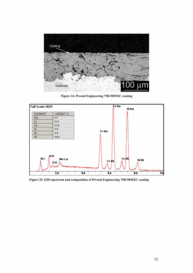
55
Figure 24. Pivotal Engineering 75B-90MXC coating
Figure 25. EDS spectrum and composition of Pivotal Engineering 75B-90MXC coating

56
Figure 26 EDS map of Pivotal Engineering coating. The four distinct phases in this coating are (1) Al, (2) Ni, (3) Ni-Cr-Fe-Mo and (4) Cr-Fe-Mo.
IV.B.11. Sulzer Metco F4301. The F4301 coating was originally developed by Sulzer Metco (Winterthur
Switzerland) as a cylinder liner coating for use in automotive applications. The
coating is predominantly iron, but contains molybdenum as an anti-scuffing agent.
Cross sections of the coating are shown in Figure 27. Because the phases in the
coating have different mechanical properties, material is removed at different rates
during the polishing process (the polishing process is essentially three body abrasive
wear). Consequently, the material removal rate of the harder phases is slower, leaving
them proud of the surface. It is possible to detect this surface topography in an optical
microscope using differential interference contrast (DIC). Using EDS, the hard phase
indicated in Figure 27 A and B has been identified as molybdenum rich. Figure 28
shows the EDS map and Figure 29 shows the EDS spectrums. The remaining phases
visible in Figure 27 C are predominantly iron, the light phase (that is not
molybdenum) being an iron alloy which is attacked with a 2% nital etch while the
bulk of the dark phase is likely to be an iron oxide, carbide or nitride (not attacked
with a 2% nital etch). The EDS map also shows the presence of a phase containing

57
aluminium. It is likely that the aluminium is present in the form of an inter metallic
iron-aluminium compound as the aluminium rich areas coincide with iron rich areas.
Figure 27. Optical micrographs of Sulzer Metco F4301 cross-section. (A) low magnification un-etched (DIC) (B) high magnification un-etched (DIC). (C) etched with 2% nital

58
Figure 28 EDS map of Sulzer Metco F4301, showing the phases (1) Mo, (2) Fe-Cr, (3) Fe-Al, (4) Fe.
Figure 29 EDS spectrum of Sulzer Metco F4301 coating: (A) etched area, (B) un-etched area, (C) hard phase (Figure 27 (C)).
IV.B.12. Sulzer Metco XPT512 and F2056. Both the XPT512 and F2056 coatings were developed for use in diesel engines and as
such are harder than the F4301 coating (F2056 being the hardest). Both coatings have
similar structures (XPT512 Figure 31 and F2056 Figure 32) and contain similar

59
elements, as shown in the EDS spectra (Figure 30). The only difference is the F2056
coating contains 20% aluminium compared to 2% in the XPT512 coating. Like the
F4301 coating, when etched with 2% nital only the light phase in either of these
coatings is attacked (Figure 32 C). The EDS maps of these two coatings are similar
(Figure 33 and Figure 34), although it appears that the area used for the map of the
F2056 coating is not representative of the coating composition (less aluminium than
would be expected).
Figure 30 EDS spectra of Sulzer Metco, (A) XPT512, (B) F2056
Figure 31 Optical micrographs of Sulzer Metco XPT512 cross-section un-etched (DIC) (A) low
magnification (B) high magnification.

60
Figure 32 Optical micrographs of Sulzer Metco F2056 cross-section, (A) low magnification un-etched (DIC) (B) high magnification un-etched (DIC), (C) etched with 2% nital
Figure 33 EDS map of Sulzer Metco XPT512 showing the distinct Fe and Al phases.
Figure 34 EDS map of Sulzer Metco F2056 showing the phases (1) Fe-Al, (2) Fe, (3) Al.

61
IV.B.13. NASA PS304. The PS304 samples were supplied by Hohman Plating and Manufacturing, Inc.
Dayton, Ohio USA. PS304 is a nickel-based, solid-lubricating, plasma-sprayed
coating developed by NASA for use in gas bearings in large turbines to eliminate the
need for lubrication systems. The composition of the powder used to deposit this
coating is shown in Table 5.
Table 5 PS304 powder composition NiCr Cr2O3 BaF2/CaF2 Ag
60% weight 20% 10% 10%
Each of the compounds in the coating has a specific function. The nickel-chromium is
the matrix material through which the other components are dispersed. The chromium
oxide is a hard material to provide wear resistance during periods of metal to metal
contact. The chromium oxide phase is indicated by arrows in Figure 37. The
remaining compounds provide solid lubrication. Silver is a low temperature solid
lubricant, while the barium and calcium fluoride compounds are high temperature
solid lubricants. In Figure 37 B, silver is visible as a white phase. The distribution of
calcium and barium fluoride can be seen in the EDS map (Figure 36). There are two
chromium-containing phases visible in the EDS map, the largest a NiCr phase and a
Cr-rich phase that does not overlap any of the other elements, which is to be Cr2O3.
DellaCorte et al. have reported on the unique running-in properties of this material
[24]. High wear rates of counter surfaces are experienced while a solid lubricating
layer is formed on the surface. Once the coating has run-in, the wear rates of the
counter surface are very low. At present this coating is relatively new and has not
been successfully applied to a specific application on a large scale. It is however
readily available and has been used successfully by individuals in various applications,
such as the wear surfaces in air cooled versions of the Norton rotary engine. An
earlier incarnation of this coating was used in the Moller International/Freedom
Motors rotary engine.

62
Figure 35 PS304 EDS spectrum and composition
Figure 36 PS304 EDS map

63
Figure 37 PS304 solid lubricating coating

64
IV.C. Rotational Tribometer Mass Loss Wear Results. In this section, seal wear was sufficiently high to enable wear rates to be quantified
through mass loss (>0.0001gm). For this work, the seal wear has been quantified as a
wear W, with the units m3m-1, volume of seal material loss per metre of sliding
distance. These units were chosen to encompass the measured and calculated
variables in these experiments (sliding distance and volume loss). An equally
appropriate unit would be the specific wear rate Wsp, which also includes the contact
load, but as the load was not varied it was not considered necessary to use this unit.
All of the seal materials tested (with the exception of silicon nitride) displayed wear
rates that were high enough to be measured using the mass loss technique on at least
one of the chamber coatings. The results of these experiments are summarised in
Table 6. To ensure statistically relevant results, the wear rates and average
coefficients of friction are averages of three or more tests. The first significant
inference of these results is that there is no relation between the wear rate and the
coefficient of friction. It is a common misconception that high coefficients of friction
are related to with high wear rates.
Nevertheless, instantaneous friction values can be used to predict the lubrication
regime, and in this case average friction values can be used as there is very little
variation in the friction force over the duration of a rotational test. By plotting typical
friction coefficients (0.025 to 0.05) on the modified Stribeck diagram produced by
Cho et al. [4] (Figure 38) it is predicted that the rotational tribometer is operating in a
mixed lubrication regime, but very close to the hydrodynamic boundary.

65
Table 6 Results from Rotational Tribometer Tests Seal Material Liner Coating Average Wear
Rate m3m-1 x10-13
Average Friction Coefficient
Four Hour Rotational Tests Si3N4 (Beamalloy) 75B-90MXC 0.000652 0.039 Total Seal TiN PS304 0.000659 0.050 DLC F4301 0.00124 0.041 N-SS PS304 0.00221 0.041 CrN (Beamalloy) 75B-90MXC 0.00262 0.042 N-SS F4301 0.00266 0.064 N-SS 75B-90MXC 0.00348 0.061 Si3N4 (Beamalloy) F4301 0.00404 0.047 Si3N4 (Beamalloy) PS304 0.00487 0.055 CrN (Beamalloy) F4301 0.00494 0.027 Mazda Cast Iron F4301 0.00638 0.054 Total Seal CrN PS304 0.00694 0.046 Total Seal WC-C PS304 0.00850 0.051 CrN (Beamalloy) PS304 0.00862 0.049 N-SS XPT512 0.826 0.094 N-SS Tungsten 2.84 0.058
Twenty Minute Starved Lubrication Rotational Tests N-SS PS304 0.0155 0.055 N-SS 75B-90MXC 0.103 0.034 N-SS F4301 0.248 0.093
Figure 38. Modified Stribeck (fc coefficient of friction vs. µω/P dimensionless bearing parameter) diagram representing a piston ring near mid stroke. Mode I to II is boundary lubrication, mode II to III is mixed lubrication and mode IV to V is hydrodynamic lubrication[4]. The highlighted area indicates the range of friction coefficients from the rotational tribometer.

66
IV.C.1. Nitrided Stainless Steel Seals Rotational Wear Test Results. In the four-hour test the lowest average wear rate of the N-SS seal is on the PS304
liner coating, followed by the F4301 and 75B-90MXC coatings. The PS304 liner
coating also had the lowest coefficient of friction, followed by the 75B-90MXC and
F4301 coatings. The low average wear rate of the N-SS seal on the PS304 coating
appears to be an anomaly when compared to the wear rates of the other seals on this
coating. In all other tests with the PS304 liner coating it was observed that the first
seal sample had a very high wear rate which then reduced with consequent tests. For
example, the wear rates for the PS304 PVD Si3N4 tests were 1.29x10⁻¹⁵ m3m-1,
1.33x10⁻¹⁶ m3m-1 and 3.29x10⁻¹⁷ m3m-1, while the results for the N-SS tests were
2.64E-16 m3m-1, 2.58E-16 m3m-1, 1.99E-16 m3m-1 and 1.65E-16 m3m-1. PS304 is a solid
lubricating coating so it is likely that the high wear during the initial tests is due to a
running in process, which leads to the development of a lubricating film on the
surface of the disc. The PS304 coating was the only material that exhibited a
detectable break-in process.
A tungsten arc sprayed liner coating and XPT512 liner coating both produced very
high seal wear rates with N-SS seal samples. After 40 minutes, the N-SS seal had
worn down to the seal holder when run against the tungsten coating. For this reason
only one test was conducted. Interestingly, the friction coefficient for this material
system was not significantly higher than that of any of the other tests, further
highlighting the independence of friction and wear.
The wear process associated with the N-SS vs. XPT512 system exhibited significant
differences compared to other tests. The XPT512 coating consistently scuffed,
causing damage to the disc surface and high seal wear. The wear rate and friction
coefficient values shown in Table 6 are only an average of two tests because the disc
was too badly damaged to conduct a third test. Scuffing occurs when the primary
wear mechanism changes from abrasive to adhesive. Scuffing is characterised by a
sharp increase in friction and temperature. The increase in friction is shown in Figure
39. In both of these tests scuffing occurred after approximately 11 minutes. Because
scuffing is associated with a different wear mechanism, the wear and friction values
cannot be compared with the remainder of the results reported here. However,

67
because of the high wear rates and surface damage associated with scuffing this
particular system can be rejected as a potential candidate.
Figure 39. Friction plots for N-SS seals on XPT512 coating showing the onset of scuffing, (A) test
one, (B) test two.
Under more severe, starved lubrication conditions the N-SS vs. 75B-90MXC system
gave the lowest wear rate and showed a lower coefficient of friction than the F4301
coating. Because of the limited lubricant supply, the friction response is influenced
more by the material couple properties than the lubricant. During the starved
lubrication tests the temperature of the disc climbs rapidly to a higher temperature
than the four hour tests. The limited supply of oil and the increased temperature have
several consequences. The oil will become contaminated, thus reducing its ability to
provide lubrication. The oil film will thin due to a decrease in viscosity and the EP
additives may become more reactive.
The average wear rate of the N-SS seals on the PS304 coating was in between the
75B-90MXC and F4301 coatings, and the coefficient of friction was the lowest of the
three. Again, the PS304 coating gave very high initial wear rates which then dropped
significantly: 3.08E-14 m3m-1 to 1.24E-14 m3m-1and finally 3.32E-15 m3m-1. The last
value is an order of magnitude lower than the lowest wear rate on the 75B-90MXC
disc of 1.68E-14 m3m-1. The starved lubrication tests may have allowed the PS304
coating to form a solid lubricating film earlier, leading an increased dependency on
the solid film than the oil film. The PS304 coating by itself may not be of great use in
the actual engine because the initial running in process causes too much wear on the
seal or seal coatings. In spite of this, it may be possible to implement a functionally
graded PVD coating that incorporates a sacrificial ‘running in’ layer. Another
possibility is the addition of a solid lubricant such as MoS4 to the coating surface to

68
reduce wear during the running in process. Either of these approaches may
sufficiently reduce the ‘running in’ wear, providing a system that would provide
satisfactory long term compression seal wear rates.
IV.C.2. Mazda 13B Apex Seal (Cast Iron). As there are similarities between the seal arrangement in the Pivotal Engine™ and a
Wankel engine three test pieces were made from a cast iron 2mm three piece Mazda
rotary apex seal from a series V 13BT engine. When these samples were tested on the
F4301 coating the average wear rate was significantly higher than that of the N-SS
seals. In contrast to the N-SS seals, the wear rate dropped significantly over the three
tests, 1.17E-15 m3m-1, 1.08E-16 m3m-1 and 2.97E-17 m3m-1. Like the PS304 coating, this
reduction in wear rate may be due to a solid lubricating film forming on the disc
surface. In this case, the film would have originated from the high volume of carbon
in the cast iron. It should be noted that the Mazda seal sample had a barrel profile,
meaning that the contact pressure is much higher (due to the small contact area) than
the other seal samples which have a flat contact area with small radii on the edges.
The different profile will also influence the thickness of the oil film between the seal
and the disc. It would have been desirable to further test this material, with the profile
modified to be more like the N-SS seal material. This would have allowed a more
conclusive comparison between the two materials.
IV.C.3. PVD Coated Seals. Several PVD coatings were tested, including: diamond like carbon (DLC) supplied by
Diameter Systems, chromium nitride (CrN), titanium nitride (TiN) and tungsten
carbide-carbon (WC-C) supplied by Total seal, as well as CrN and silicon nitride
(Si3N4) supplied by Beamalloy Ltd. With the exception of the PS304 disc, the Total
Seal coatings gave a significant decrease in the seal wear rate and will be discussed in
section III.D.1. The average wear rates for PVD coated seals on the PS304 disc were
higher than on any of the other disc coatings, and again the wear rates dropped
significantly with consequent tests.
The Beamalloy coated seals did not offer a great increase in performance over an
uncoated seal. These two coatings were relatively thin (approximately 1.2µm) and did
not have sufficient bond strength with the nitrided stainless steel substrate. The CrN

69
coating wore through an abrasive mechanism, similar to the N-SS seals. Because the
coating was so thin it offered little extra protection, wearing through during a four
hour test. The SiN coating failed/wore through a slightly different process (Figure 42
A). In addition to abrasive wear, the coating fractured and was removed from the
surface. This indicates poor adhesion to the substrate and or high internal stresses.
With the exception of the N-SS seal on the XPT512 coating and the Si3N4 coated seal
(on all coatings tested against), the seal samples wore by two and three body abrasive
wear. This is characterised by striations in the direction of motion, visible in Figure 42.
Unlike the seal samples, the wear of the discs could not be quantified. The damage to
the disc surfaces was minimal as can be seen in Figure 40 A and B.
Figure 40. (A) Worn 75B-90MXC disc surface. (B) Worn F4301 disc surface.
IV.C.4. Summary of Rotational Mass Loss Tests. From the results in Table 6 several material couples were eliminated as potential
compression seal and chamber coating materials. The Pivotal Engineering arc sprayed
tungsten liner coating gave highest seal wear rate recorded and for this reason was
eliminated from any further testing (or microstructural analysis). The PS304 liner
coating gave high initial seal wear rates and as such is not a suitable material for use
in the engine so was also eliminated. The XPT512 liner coating repeatedly scuffed
when tested against the N-SS seal, this should have eliminated this material couple
but it was later found that this behaviour was only apparent on the rotational
tribometer. The CE17 arc seal material was tested primarily to investigate the wear
response of the different chamber coatings, however very little information was
gained through these tests. The only compression seal materials not eliminated from

70
further testing were the Total Seal PVD coated seals (TiN, CrN, WC-C) and silicon
nitride.
IV.D. Extended Duration Tests. The remainder of tests conducted on the rotational tribometer were carried out over
longer durations. The compression seal materials selected for testing over an extended
period include, TiN, CrN, WC-C and silicon nitride. These materials were selected for
further testing because they displayed minimal (immeasurable) wear during the four
hour test. Because the wear rates of the seal materials and coatings in this section
were so low, no change in mass could be detected even after extended test periods. To
quantify the seal wear, the worn surface area was measured at approximately eight
hour intervals. The results for these tests are shown in Figure 41.
IV.D.1. PVD Coated Seals. The WC-C coated seal was tested against the F4301 disc coating for a period of
approximately eight hours. At the conclusion of testing the coating had completely
worn through in some areas and there was no measurable mass loss, meaning neither
the mass loss nor the surface area wear quantification method was suitable. For this
reason, the result from this material is not shown in either Table 4 or Figure 41. The
WC-C coating displayed lower wear rates than those presented in Table 4 and higher
wear rates than those in Figure 41. The worn surface of the WCC seal is shown in
Figure 42 B, where it can be seen that this seal has worn through an abrasive wear
mechanism and not failed like the Si3N4 film shown in Figure 42 A.
Of the remaining seal and chamber coating combinations, the highest wear was
recorded with the CrN coated seal running on the F4301 disc coating. The higher
wear rate of the CrN coated seal is likely to be due to the slight reduction in hardness
over the TiN coated seals. The CrN coated seal was not tested on either the XPT512
or F2056 coatings because it was expected, based on the results with TiN coated seals,
that the wear would be even higher than that on the F4301 coating.
The TiN coating provided greater wear resistance than the CrN or WC-C coatings.
The lowest TiN wear rates were recorded when run against the F4301 coating,
followed by the XPT512 and F2056 coatings respectively. The difference in the wear
rates for the TiN coated seals can be related to the distribution and volume of hard

71
materials in the disc coatings. These results show that seal wear rate increases with
the increasing hardness of the disc coatings. The F4301 coating is softer than the
XPT512 and F2056 coatings and contains molybdenum, which acts as an anti scuffing
agent. The composition of the XPT512 and F2056 coatings are similar, although the
F2056 coating is harder.
The TiN coated seal was tested twice against the F4301 disc coating because the oil
system failed during the first test at around twenty hours. This can be seen as the area
of high friction in the friction plot (see Figure 43). This period corresponds with a
jump in percentage of worn surface area in Figure 41. Although the first test was run
without oil for a period of time and there was a subsequent increase in the worn
surface area, both tests tended towards the same worn surface area. The duplication of
this test also serves to validate the repeatability of this test method.
IV.D.2. Silicon Nitride Seals. Of all of the materials tested, reaction bonded silicon nitride was the most wear
resistant. Silicon nitride seal samples were tested on the F4301 and F2056 coated
discs. Silicon nitride was not run against the PS304 coating because the fluorine in the
solid lubricating component of the coating reacts with the silicon nitride, breaking
down both materials. The wear rates measured in these tests were less than half that of
the TiN coated seals. Unlike the TiN coated seals, the wear rate of the silicon nitride
seals appears to be reasonably independent of the counter surface material. The
friction plots of the silicon nitride seals on the F4301 and F2056 coatings are shown
in Figure 45 and Figure 46 respectively. The friction force in Figure 46 is
significantly lower than the friction force in Figure 45. This may in part be due to
material properties but is more likely a result of different seal geometry (the silicon
nitride seals were hand made). The seal tested on the F4301 coating had a smaller
radius on the leading edge than the seal used on the F2056 coating. Because of the
different geometry, the friction forces from these two tests cannot be compared to the
other results. During both tests the seal did not wear evenly across its face. This was
because the seal was not as flat (due to manufacturing) or conforming as the stainless
steel seals. The effect of this is that the specific contact force is much higher due to
the lower contact area, making the test more severe.

72
In addition to abrasive wear, the silicon nitride seals exhibited tribo-chemical wear in
some areas. This is identified by the polished appearance of the seal surface (Figure
47). In this case the tribochemical wear is a secondary wear mechanism and as such
does not significantly contribute to the overall wear of the seal.
Figure 41. Percentage of surface area time plot for seal samples with low wear rates.
Figure 42. Optical micrographs of the wear surface of (A) Si3N4 coated seal tested against F4301
coating. (B) WCC coated seal tested against F4301.

73
Figure 43. Friction plot for TiN coated seal on F4301 coated disc test #1
Figure 44 Friction plot for TiN coated seal on F2056 coated disc

74
Figure 45. Friction plot for silicon nitride seal on F4301 coated disc.
Figure 46. Friction plot for silicon nitride seal on F2056 coated disc.

75
Figure 47. Optical micrograph of the wear surface of silicon nitride seal. (A) tribochemical wear.
(B) abrasive wear.

76
IV.E. Fired Engine Test Results. A one litre twin chamber engine was used to test the seal and chamber coatings. The
initial test was conducted with one chamber having CrN coated seals and the other
having TiN coated seals. Both sets of chamber surfaces were coated with F4301.
Having two seal coatings tested in the same conditions allowed the wear rates of both
coatings to be compared, as well as the relativity between the results from the engine
and the tribometer. During the test, the engine was run at 3000 to 4000 rpm with a
load of approximately 6 kW.
The first engine test was prematurely stopped because of an unrelated component
failure. However after four hours of running, both sets of seals showed significant
wear on the ends nearest the corner of the chamber. The coatings had been removed
from the first 12mm – 15 mm of the seals (this area is indicated in Figure 48). The
TiN seal had slightly less material removed than the CrN seal. Because of the damage
caused by the engine failure, it was not possible to measure the mass loss of any of the
seals or quantify a wear rate.
Figure 48 Compression seal configuration. Areas of high wear are indicated in red.

77
A second engine test was conducted using TiN coated seals against F4301 and
XPT512 chamber coatings. After approximately 40 hours running the TiN coating had
completely worn through along the length of all six seals. Unlike the tribometer tests,
there was no scuffing from the N-SS seal running on the XPT512 coating (after the
TiN had worn off). Again, the wear rates of the seals could not be quantified because
of other factors.
Although the wear rates of the seals in the engine were not quantifiable, it was
obvious that the wear rates in the engine were much higher than those from the
tribometer. The speed and loads on the tribometer were selected to be equivalent to
the engine running at 5000 rpm with a load of 70 kW. Even though the wear rates
were very different, the wear mechanisms of the seals from the engine and samples
from the tribometer were the same. Figure 49 A and B are optical images of a seal
used on the tribometer and engine respectively. Both of these images indicate two and
three body abrasive wear with similar sized wear tracks.
Figure 49. Optical micrographs of (A) wear surface of N-SS seal used on tribometer. (B) wear
surface of CrN coated seal used in engine. Both seals were run against F4301 coating (CrN
coating completely removed).
IV.E.1. Compression Seal Analysis. To gain a better understanding of the wear system in the engine, the profile of a worn
side compression seal was investigated, as shown in Figure 50. The first observation
from Figure 50 is that the profile of the wear surface of the seal is almost flat and
normal to the top surface of the seal. This indicates that the seal has very little
movement in the seal groove. If the seal had movement in the groove it would be
anticipated that a rounded wear profile would be present. The second observation is

78
the large difference in the volume of material removed along the length of the seal.
The greatest wear occurs on the end of the seal in the corner of the chamber.
From this analysis, a compression seal with a larger radius or full barrel profile may
ultimately provide a longer engine life. The barrel profile can develop thicker oil films
for a longer period of time as more material would have to be removed from the seal
to eliminate the radius. In addition to the longer lasting profile, the barrel face would
reduce the contact force exerted on the compression seal because the combustion gas
pressure is more balanced across the seal.
Figure 50. Side compression seal wear profiles, top of seal is on the left hand side of the image.

79
IV.E.2. Alternative Compression Seal Designs. The seal wear in the Pivotal Engine™, as well as being higher than on the tribometer,
was much higher than would be expected in a conventional two stroke engine
producing similar power. The accelerated wear in the Pivotal Engine™ may be caused
by a number of reasons, including increased temperatures, lubrication starvation and
high contact forces between the seals and the chamber. Upon disassembly of an
engine, there are no obvious signs of over heating or lubrication starvation. This
leaves contact forces as the most likely cause of high wear.
It was hypothesised that the wear on the ends of the seals may be due to centripetal
forces from the movement of the piston. This would explain the wear on the ends of
the side and front seals. As the side seals are pushed forward, the bevel would force
the end of the side seal onto the side plate as well as forcing the ends of the front seal
against the exhaust block. To test this hypothesis, the piston motion was analysed
using Solid Works and Cosmos Motion in order to determine the magnitude of the
centripetal forces on the seals. Figure 51 shows the force exerted on the curved
surface of the chamber (front seal) from the centripetal acceleration of the seal at 3000
and 6000 rpm against the crank angle.
Figure 51 Analysis of centripetal compression seal loading (A) 3000rpm (B) 6000rpm.
The centripetal force exerted on the front seal will be distributed along its entire
length. Even at 6000 rpm the centripetal force is small compared to that from
combustion pressure (35N compared to approximately 650N). However if the
centripetal force is not uniformly distributed along the front seal point loadings could
become significant. Because there is no information on the clearances and distortion
of the components in the Pivotal Engine™ it is impossible to estimate any point

80
loadings. However at the engine speed of 3000 to 4000 rpm the centripetal seal loads
are minimal and should not cause the wear rate of the seals to be accelerated to the
extent that was seen in the engine.
It is possible that high wear on the ends of the seals may be due to the thermal
expansion of the front seal generating high loads in the corners of the chamber. To
test this theory, seals were manufactured with a square detail on the corners,
eliminating the bevel that would force the seals into the corner of the chamber. A
CAD image of this seal design is shown in Figure 52 B. However, due to outside
influences this seal configuration was never tested.
Figure 52. Alternative seal design (A) original seal corner detail (B) proposed seal corner detail.
A second alternative to the current seal design is shown in Figure 53. A piston and
seal arrangement was designed in such a way that the front and side seals are isolated
from each other through the use of a corner seal. Figure 53 shows the finished piston
and an exploded view of the seal arrangement. The exploded view has two alternative
front seal options. The two piece design is to provide better gas sealing than the one
piece design. The small piece of the seal will wear faster than the long piece because
the back area exposed to gas pressure is larger than the front area in contact with the
chamber. If the front seal is slightly under size (length), the front edge of the small
piece will wear until the end clearance is taken up. If the seal is oversize the ends of
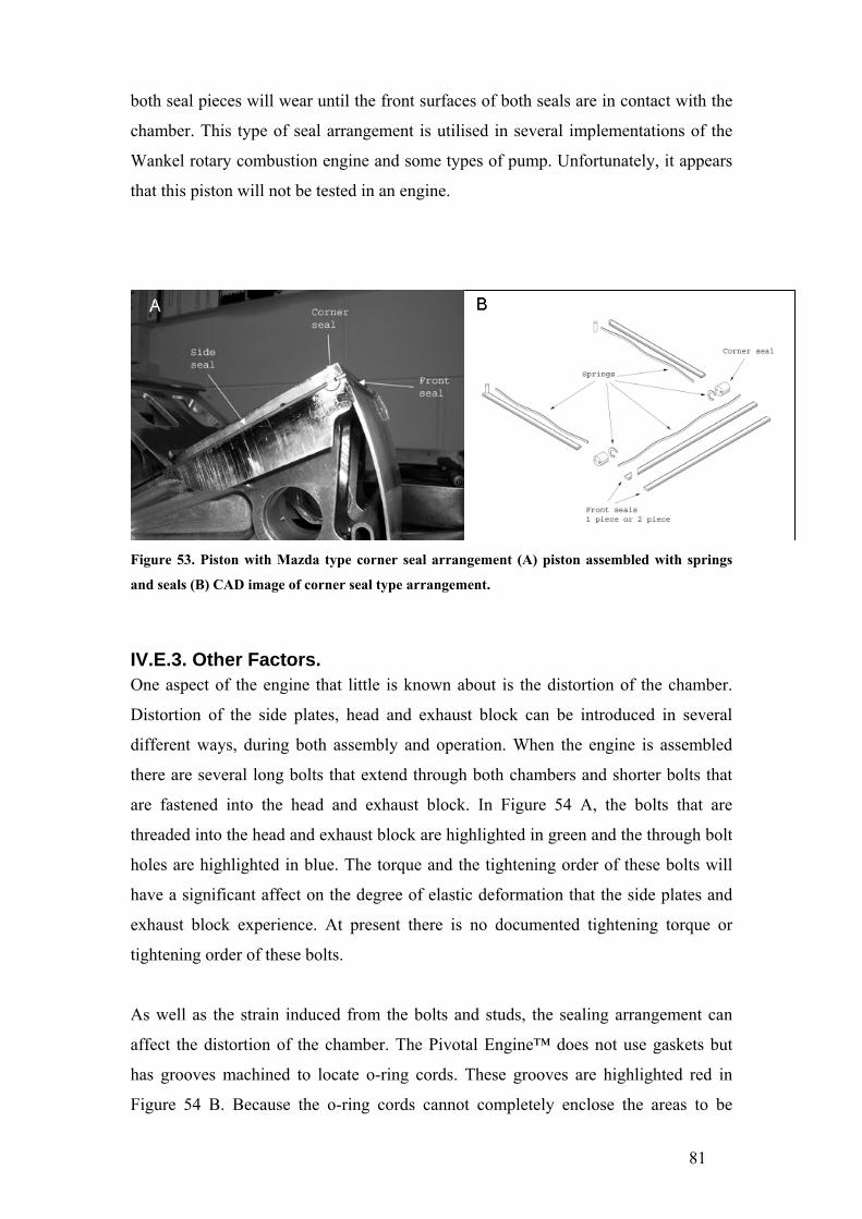
81
both seal pieces will wear until the front surfaces of both seals are in contact with the
chamber. This type of seal arrangement is utilised in several implementations of the
Wankel rotary combustion engine and some types of pump. Unfortunately, it appears
that this piston will not be tested in an engine.
Figure 53. Piston with Mazda type corner seal arrangement (A) piston assembled with springs
and seals (B) CAD image of corner seal type arrangement.
IV.E.3. Other Factors. One aspect of the engine that little is known about is the distortion of the chamber.
Distortion of the side plates, head and exhaust block can be introduced in several
different ways, during both assembly and operation. When the engine is assembled
there are several long bolts that extend through both chambers and shorter bolts that
are fastened into the head and exhaust block. In Figure 54 A, the bolts that are
threaded into the head and exhaust block are highlighted in green and the through bolt
holes are highlighted in blue. The torque and the tightening order of these bolts will
have a significant affect on the degree of elastic deformation that the side plates and
exhaust block experience. At present there is no documented tightening torque or
tightening order of these bolts.
As well as the strain induced from the bolts and studs, the sealing arrangement can
affect the distortion of the chamber. The Pivotal Engine™ does not use gaskets but
has grooves machined to locate o-ring cords. These grooves are highlighted red in
Figure 54 B. Because the o-ring cords cannot completely enclose the areas to be

82
sealed a significant amount of sealant is used. The type of sealant used between the
mating faces of the engine can cause significant changes in clearances and therefore
strain and distortion of the chamber.
The last two mechanisms of chamber distortion occur when the engine is running. The
first is due to the differing rates of thermal expansion between the aluminium
chamber and the steel bolts. This problem is compounded by using bolts with large
differences in length. To overcome differences in rates of thermal expansion, head
bolts and through bolts in rotary engines are usually waisted to reduce rigidity so
excessive strain is not applied to the aluminium components. The last mechanism of
chamber distortion is from combustion pressure during the power stroke forcing the
chamber walls apart. The area exposed to high pressure is highlighted in Figure 54 A.
In the Pivotal Engine™ this problem is compounded due to the design of the side
plates. A relatively large flat part inherently has low stiffness. Combined with the
volume of material removed from the back of the side plate for coolant cavities, the
stiffness is greatly reduced.
The distortion of the chamber could cause excessive seal wear in two ways: either the
reduction of clearances causing high seal loadings, or the compression seals may have
sufficient stiffness that the combustion pressure does not force the seal to conform to
the distorted chamber. This would cause the seals to experience high point loadings.
The best way to analyse these factors would be to perform a finite element analysis of
the engine components.
Bore (chamber) distortion can be a problem in both conventional two and four stroke
engines reducing piston ring life and increasing oil consumption. To prevent this
problem, several low volume engine manufacturers are now designing and producing
‘mono block’ engines where the cylinder head and cylinder are cast as one part to
increase the rigidity of the engine.

83
Figure 54. The Pivotal Engine™, (A) with the area of high combustion pressure highlighted in red, threaded bolt holes highlighted in green, through bolt holes highlighted in blue. (B) with the o-ring cord grooves highlighted in red.

84
IV.F. Reciprocating Tribometer. Reciprocating tests were run for approximately twenty hours. The increased test
duration over the rotational tribometer is because of the significantly lower speed,
which gives lower sliding distance per unit time. The reciprocating tribometer must
run nine times as long as the rotational tribometer for the equivalent sliding distance.
However, the more severe lubrication and therefore wear conditions on the
reciprocating tribometer mean that the wear of the test block is high enough to be
measured using the mass loss method. The test block wear rates were quantified in the
same manner as the seal samples, i.e., the mass was recorded before and after each
test and the difference used to calculate the wear rate. The appearance of the test
block is much more similar in appearance to the wear surfaces observed in the fired
engine tests.
IV.F.1. Reciprocating Tribometer Results. Due to time constraints, only the F4301 liner coating was tested versus several seal
materials (TiN, CrN, Cast iron and N-SS) on the reciprocating tribometer. The results
of these tests are summarised in Table 7. The best seal material tested on the
reciprocating tribometer was Total Seal TiN. Although there was no measurable mass
loss at the conclusion of a twenty hour test a significant area of the 4µm thick coating
had been removed from the seal surface. This wear rate is much closer to what was
observed in a fired engine. Similarly, the 4µm thick CrN coating had worn through at
the conclusion of a twenty hour test (with no measurable mass loss). In these tests the
CrN coating is ranked second to the TiN coating due to the fact that a greater area had
been removed from the CrN coating. Also of note is that the wear rate of the F4301
test block was significantly lower against the TiN coated seal than the other three seal
materials.
When tested on the rotational tribometer, the N-SS seal gave lower wear rates (Table
6) than the Mazda cast iron seal. This contradicts the results obtained on the
reciprocating tribometer, where the cast iron seal gives lower wear rates than the N-
SS seal. The most likely reason for this change in results is that the different seal
profiles have a more pronounced affect on seal wear because of the changing
lubrication regimes. From these tests, the TiN coated seal has been identified as
having the lowest wear rate while the N-SS seal had the highest. Additionally, the

85
F4301 test block had the lowest wear rate against the TiN coated seal. The cast iron
seal gave the highest wear rate of the F4301 test block but this is not considered to be
as important as the seal wear rate, since the engine life is currently limited by the seal
wear rate.
Table 7 Wear rates from reciprocating tests. Seal Material Oil Average Seal
Wear Rate m3m-1 x10-13
Average chamber coating Wear Rate m3m-1 x10-13
TiN Morris race 2 0.000 0.0189 CrN Morris race 2 0.000 0.0702 Mazda Cast Iron Morris race 2 0.00171 0.0873 N-SS Morris race 2 0.00225 0.0511 N-SS Castrol A747 0.000562 0.000 N-SS ELF HTX976 0.00111 0.0345 N-SS Maxima 927 0.00152 0.572 N-SS Mobil 0.438 Not measured
On the reciprocating tribometer, much more information can be gained from the
friction response of the system than the rotational tribometer. Again, there is no
correlation between the magnitude of the friction force and wear rates.
Friction plots from the reciprocating tribometer are shown in Figure 55 A and B.
These plots contain friction force data from one complete crankshaft revolution.
Because, friction force is always in the opposite direction to the relative surface
velocity the sign of the friction force must change for each crankshaft revolution. At
the turnaround points the relative velocity between the seal and the test block drops to
zero and because the velocity is zero at this point the friction force must also be zero.
Between the turnaround points the relative velocity increases to a maximum at mid-
stroke.
The reversal in wear resistance between the N-SS and cast iron seals from the
rotational to reciprocating tribometers may be explained by the different seal profiles
influencing the lubrication regime in which the system is operating. As noted earlier,
the cast iron seal has a barrel type profile, while the N-SS seal has a flat face with
radii on the edges. The barrel profile appears to help the transition from a mixed to
hydrodynamic lubrication regime through the mid-stroke. This is indicated by an
increase in friction force with the increase in velocity (Figure 55 B). The friction force

86
in the mixed lubrication regime is less dependent on velocity, therefore it is probable
that the system in Figure 55 A is in a mixed lubrication regime. Because the N-SS
seal is operating in a mixed lubrication regime through the mid-stroke it is likely to
have a higher wear rate than the Mazda cast iron seal which, is operating in a
hydrodynamic lubrication regime through the mid-stroke.
Even though these two seal materials are operating in different lubrication regimes
through the mid-stroke, the actual seal wear rates are not greatly different. This is
because most of the seal wear (and test block wear) occurs at the turnaround points
where both are operating in a boundary lubrication regime. The transition to a
boundary lubrication regime is identified by the peaks in friction force at the
turnaround points in Figure 55 (A), (B) and (C). As the velocity tends to zero at the
turnaround point the oil film thickness decreases, allowing metal-to-metal contact
between the seal and the coating with an associated increase in friction and wear.
The lower tribometer speed during the acquisition of the friction data for the Mazda
cast iron seal was not intentional. The tribometer speed is reduced to acquire the
friction data by lowering the driving frequency of the motor to 10Hz (without an
actual speed feedback). The reduction in speed also reduces the torque that the motor
can deliver. This means that the high friction force with the Mazda apex seal reduced
the tribometer speed.
Figure 55. Friction plots from reciprocating tests, (A) Boundary lubrication at turnaround points, mixed lubrication through mid-stroke. (B) Boundary lubrication at turnaround points, hydrodynamic lubrication through mid-stroke.
In Figure 56 there are additional peaks after the turnaround point. These peaks are due
to a stick-slip phenomenon. The friction force between the seal and the test block is
high enough that the test block and carrier are deflected with no relative movement
between the contacting surfaces. When the force is sufficiently high to overcome the

87
friction force the test block and carrier will try to return to an equilibrium position.
However because of the sudden drop in force, the test block will tend to over-shoot
the equilibrium position. The test block must then travel in the same direction as the
seal sample to return to the equilibrium position, reducing the relative velocity and
again allowing metal to metal contact causing the cycle to repeat. In part this is caused
by the stiffness (or lack of) of the tribometer, allowing the test block to deflect. There
was a general trend for this type of friction response to occur later in the test period.
The most likely reason for this is that the increase in temperature reduces the oil
viscosity causing more severe boundary lubrication conditions near the turnaround
points.
Figure 56 Friction plots from reciprocating test, boundary lubrication and stick-slip at
turnaround points, mixed lubrication through mid-stroke
IV.F.2. Test Block Surface Analysis. The reduction in size of the test block on the reciprocating tribometer over the test
disc on the rotational tribometer allowed analysis of the wear surface. The first
significant aspect of the surface topography of the test block is the high surface
porosity as shown in Figure 57 A. A conservative estimate using a pixel count of the
processed image (Figure 57 B) gives a surface porosity of 40%. The high surface
porosity dominates surface roughness measurements and preclude intentional surface
texturing (such as plateau honing). There is no significant deviation in surface
roughness between a test block dressed with new 400 grit silicon carbide paper and a
test block dressed with new 1200 grit silicon carbide paper (average Ra values of 0.52
µm and 0.54 µm respectively). Because the different silicon carbide papers do not
affect the macroscopic surface topography, it would also be expected that the wear
process would not alter the macroscopic surface properties, and this is in fact the case.
The surface roughness vales (Ra of 0.54 µm) are not discernible from unworn and the

88
surface porosity is not affected by the wear test (shown in Figure 57). It is possible
that the porosity will act as a lubricant reservoir, however the voids are much larger
than most intentionally created surface features so may not be as beneficial.
Figure 57 F4301 test block surface at turnaround point. (A) raw image, the worn area is blue. (B) processed image showing approximately 40% surface porosity.
On a microscopic level, the worn and unworn surfaces are very different. Figure 58
shows an SEM image of an unworn area of the test block surface at 1000x
magnification. The visible surface texture results from the test block being dressed
with 600 grit silicon carbide paper. This surface is very different from the worn
surfaces shown in Figure 59 A and B, where only the deepest valleys from the
original surface texture remain. Abrasive wear is responsible for the removal of most
of the original surface features, as indicated by wear striations in the sliding direction.
There is also a polishing type wear mechanism present although this will remove
orders of magnitude less material than abrasive wear.
In addition to abrasive wear and polishing, plastic flow is evident. In plastic flow,
material is ‘smeared’ over the edges of pre-existing surface features. The repeated
plastic deformation eventually causes flakes of material to be removed from the
surface in a fatigue-like process. Plastic flow is observable on the wear surface at
both the mid stroke and the turnaround points (highlighted in Figure 60). There are
also areas on the wear surface where entire ‘splats’ have been removed from the
coating surface, such as shown at the top right corner of Figure 60 A.

89
Figure 58 SEM image of un-worn area showing initial surface texture.
Figure 59 SEM images of worn areas (arrows indicate sliding direction) on F4301 coating, showing: (A) abrasive wear, (B) abrasive wear and polishing.
Figure 60 SEM images of worn areas (arrows indicate sliding direction) on F4301 test block. (A) turnaround point (B) mid stroke. Highlighting indicates areas of plastic flow.

90
IV.F.3. Lubricant Tests. In addition to testing different material combinations, different oils were tested on the
reciprocating tribometer. The oils include Morris race 2 (which was used for all other
tests), Elf HTX976, Castrol A747, Maxima 927 and general purpose Mobil two-stroke
oil. The Morris and Elf oils are fully synthetic race oils, while the Castrol and
Maxima oils are synthetic castor blends. These oils are specifically formulated for
high performance applications. For example, the Castrol oil is specified for water
cooled engines that run from 12000 to 18000 rpm. Of these four oils only Morris
specifies that it exceeds API TC requirements. The Mobil oil is a mineral oil, meeting
TC requirements. In contrast to the other oils, the Mobil oil is recommended for use in
lawnmowers, chainsaws and motorcycles.
Perhaps the biggest governing factor in the use of these oils (in the intended
application of the Pivotal Engine™) is cost. The four high performance oils range
from $30 NZD to $60 NZD per litre while the Mobil oil is less than $10 NZD per litre.
Even if an engine is running at 200:1 fuel oil ratio the use of the high performance
oils will have a significant contribution to the overall running costs.
It is interesting to note that the different oils have as much effect on the system wear
rates as the different materials. To ensure consistency and relevance to other results
all of the oil tests used N-SS seals and F4301 coated test blocks. The lowest test block
wear rate was recorded with the Castrol A747 oil. The test block wear rate was even
lower than that of the test block run against the TiN coated seal, in this case no mass
loss was measured. Of all the oils tested, the Castrol oil also provided the best wear
protection for the N-SS seal. The seal wear rates with the Elf, Maxima and Morris oils
are reasonably close, however the Elf oil definitely offers better wear protection to the
test block than the other two oils. The high test block wear rate with the Maxima oil is
due to minor scuffing at the start of the test, ideally this test would have been repeated
but time constraints did not allow this.
The most significant result from the oil tests is the extremely high seal wear rate
recoded with the Mobil oil. Based on cost alone it would be expected that this oil
would not perform as well as the high performance oils. However it highlights a
danger of developing an engine using only high performance oils. If the Mobil oil (or

91
any other general purpose oil) was used in a Pivotal Engine™ it is likely that it would
not last more than a couple of hours before the compression seals failed.
92
V. Conclusions. It was found that the test results from the rotational tribometer have little relevance to
how a material couple perform in a fired engine. Seal wear rates on the rotational
tribometer were much lower than in the engine. There was also no detectible wear of
the chamber coatings on the tribometer (in most cases). In addition to the
significantly lower wear rates, one particular material couple (XPT512 and N-SS)
continually scuffed when tested on the rotational tribometer while performing as well
as other material combinations in a fired engine. The reason for these very different
system wear responses is because the conditions on the tribometer do not represent
the conditions in the fired engine. Most importantly, the rotational tribometer operates
in a mixed-hydrodynamic lubrication regime, minimising wear. The engine will
operate in boundary, mixed and possibly hydrodynamic lubrication regimes at
different points in the cycle. Most wear occurs while the engine is operating in the
boundary lubrication regime.
The reciprocating tribometer was designed and built to overcome all of the
deficiencies of the rotational tribometer. Most importantly the reciprocating motion
allows the transition between boundary, mixed and hydrodynamic lubrication regimes.
As a result the system wear observed on the reciprocating tribometer is much more
representative of the system wear in the actual engine. An indication of this is that the
test blocks from the reciprocating tribometer have a similar wear pattern to the side
plates of the Pivotal Engine™, areas of high wear at the turnaround points with less
wear through the mid-stroke.
From the testing conducted on the reciprocating tribometer, the best wear system was
found to be TiN coated seals run against F4301 coated test blocks with Morris race 2
oil. From standardised tests (N-SS seals against F4301 coated test blocks) used to
compare different oils it was found that the Castrol A747 oil provided the best wear
protection to both the seal and test block. It should be noted that the use of different
oils had as much affect on the system wear as different material combinations. A
Mobil general purpose two-cycle oil produced seal wear rates two orders of
magnitude higher than the other high performance oils. Although not tested on the
reciprocating tribometer, silicon nitride seals are likely to significantly increase the

93
service life of the Pivotal Engine™. This material has been shown to significantly
increase the seal and chamber service life in the Mazda Wankel engine.
V.1. Recommended Future Work. It is recommended that silicon nitride seals be tested on the reciprocating tribometer
and in a fired engine to verify this material as having the desired wear properties to
increase the service life of the Pivotal Engine™
To date, all of the fired engine tests and most of the tribometer testing has been
conducted using full synthetic racing two-cycle oil. It may be anticipated that this type
of oil would be used in an aircraft application but for power generation and
applications where low running costs are important the use of these oils is likely to be
prohibitively expensive. For this reason, it is recommended that testing should also be
conducted with different oils to ensure that the Pivotal Engine™ can endure being run
with cheaper oils.
Since the wear rates from the reciprocating tribometer, as well as published data from
similar experiments, all show compression seal/piston ring wear rates significantly
lower than those recorded in the Pivotal Engine™, further investigation should be
carried out into the actual forces in the fired engine and the distribution of these forces
on the compression seals.
Forces that have not been considered in this study arise primarily from the distortion
of the combustion chamber. Because the compression seals have a limited ability to
conform to the chamber, there will be areas of the seal that are exposed to high
localised contact forces, which may be the cause of the high recorded seal wear rates.
There are three areas that should be investigated with regard to chamber distortion:
(1) the tightening order and tightening torque of the bolts and studs that hold the side
plates against the head and exhaust block, (2) the thermal expansion and stiffness of
the alloy steel studs and bolts compared to the aluminium side plates, head and
exhaust block, and finally (3) the distortion of the relatively thin side plates due to
combustion pressure.

94
At this stage of the development of the engine, it is recommended that a document is
drafted containing clearances and tolerances for critical engine components, as well as
an assembly guide including a procedure for the assembly and disassembly of the
engine, including tightening torques and orders for all threaded fasteners. This type of
document is required to eliminate uncontrolled variables between engines, ensuring
that all test engines are similar, and that test results are in fact representative of any
modification and not artifacts of unknown/uncontrolled factors.

95
References. 1. Setright, L.J.K., Some unusual engines. 1975, London: Mechanical
Engineering Publications. 2. Andersson, P., J. Tamminen, and C.-E. Sandstrom, Piston ring tribology. A
literature survey. VTT Tiedotteita - Valtion Teknillinen Tutkimuskeskus, 2002(2178): p. 8-105.
3. Rabute, R. and T. Tian, Challenges involved in piston top ring designs for modern SI engines. Journal of Engineering for Gas Turbines and Power, 2001. 123(2): p. 448-459.
4. Cho, S.-W., S.-M. Choi, and C.-S. Bae, Frictional modes of barrel shaped piston rings under flooded lubrication. Tribology International, 2000. 33(8): p. 545-551.
5. Muroki, T. and J. Miyata. MATERIAL TECHNOLOGY DEVELOPMENT APPLIED TO ROTARY ENGINE AT MAZDA. in International Congress and Exposition - Society of Automotive Engineers. 1986. Detroit, MI, Engl: SAE, Warrendale, PA, USA.
6. Woydt, M. Materials-based concepts for an oil-free engine. in World Tribology Congress. 1997. London: Mechanical Engineering Publications Limited.
7. Winn, A.J., D. Dowson, and J.C. Bell, Lubricated wear of ceramics Part II: the wear and friction of silicon nitride and steel in the presence of mineral oil or an ester based lubricant. Tribology International, 1995. 28(6): p. 395-402.
8. Winn, A.J., D. Dowson, and J.C. Bell, Lubricated wear of ceramics. Part I: The wear and friction of silicon nitride, alumina and steel in the presence of a mineral oil based lubricant. Tribology International, 1995. 28(6): p. 383-393.
9. Dynamic-Ceramic, http://www.dynacer.com/: Crewe Hall, England. 10. Shimizu, R., et al. Mazda 4-rotor rotary engine for the Le Mans 24-hour
endurance race. in International Congress and Exposition, Feb 24-28 1992. 1992. Detroit, MI, USA: Publ by SAE, Warrendale, PA, USA.
11. Lyubimov, V.V., et al., Development and testing of multilayer physically vapour deposited coatings for piston rings. Surface & Coatings Technology, 1992. 52(2): p. 145-151.
12. Holmberg, K., Operational reliability &systematic maintenance. Finnish J. ed. 1991, London: Elsevier Applied Science.
13. Whittaker, L.V. and A. Matthews, Comparison of a simulated 'in-service' rig test with a standardised laboratory abrasion test. Surface and Coatings Technology, 2004. 177-178: p. 603-610.
14. Ma, Z., et al., Break-in liner wear and piston ring assembly friction in a spark-ignited engine. Tribology Transactions, 1998. 41(4): p. 497-504.
15. Hill, S.H., S.E. Hartfield-Wunsch, and S.C. Tung, Bench wear testing of common gasoline engine cylinder bore surface/piston ring combinations. Tribology Transactions, 1996. 39(4): p. 929-935.
16. Akalin, O. and G.M. Newaz, Piston ring-cylinder bore friction modeling in mixed lubrication regime: Part II - Correlation with bench test data. Journal of Tribology, 2001. 123(1): p. 219-223.
17. Akalin, O. and G.M. Newaz, Piston ring-cylinder bore friction modeling in mixed lubrication regime: Part I - Analytical results. Journal of Tribology, 2001. 123(1): p. 211-218.
18. Ravikiran, A., Wear quantification. Journal of Tribology, Transactions of the ASME, 2000. 122(3): p. 650-656.
96
19. Truhan, J.J., J. Qu, and P.J. Blau, The effect of lubricating oil condition on the friction and wear of piston ring and cylinder liner materials in a reciprocating bench test. Wear15th International Conference on Wear of Materials, 2005. 259(7-12): p. 1048-1055.
20. Kazmierczak, A., The new ring seal of the combustion engines and its surface free energy. Industrial Lubrication and Tribology, 2004. 56(1): p. 6-13.
21. Lou, H.Q., et al., Effect of deposition conditions on the characteristics of reactively sputtered titanium nitride films. Surface & Coatings Technology, 1997. 90(1-2): p. 123-127.
22. Friedrich, C., et al., Measurement of the hardness of hard coatings using a force indentation function. Thin Solid Films Proceedings of the 1996 23rd International Conference on Metallurgical Coatings and Thin Films, Apr 22-26 1996, 1996. 290-291: p. 216-220.
23. Rebholz, C., et al., Structure, mechanical and tribological properties of nitrogen-containing chromium coatings prepared by reactive magnetron sputtering. Surface and Coatings Technology, 1999. 115(2): p. 222-229.
24. DellaCorte, C., A.R. Zaldana, and K.C. Radil, A systems approach to the solid lubrication of foil air bearings for oil-free turbomachinery. Journal of Tribology, 2004. 126(1): p. 200-207.