Embed Size (px)
Citation preview
DEPARTMENT OF THE INTERIOR
UNITED STATES GEOLOGICAL SURVEYGEORGE OTIS SMITH, DIRECTOR
BUIXETTN" 373
THE SMOKELESS COMBUSTION OF COAL IN BOILER PLANTS
t
WITH A CHAPTER ON CENTRAL HEATING PLANTS
BY
D. T. RANDALL AND H. W. WEEKS
.WASHINGTONG O V K K N M E N T P li I N T ING O !<' I1' I C E
1909

CONTENTS.
Page.Introduction............................................................... 5
The problem and its solution............................................ 5Investigation of industrial plants....................................... 5
Scope and purpose................................................ 5Summary of conclusions............................................ (iPersonnel......................................................... 7Method of collecting data.......................................... 7Sizes of coal....................................................... 7iDefinition of boiler horsepower...................................... 8Determination of total heating surface............................... '9
Tests by the Geological Survey......................'................... 9General statement.................................................. 9Summary of conclusions............................................ 10
Representative boiler plants burning coal without smoke..................... 11General statement...................................................... 11Plants with mechanical stokers ................'.......................... 12
Overfeed stokers.................................................. 12Chain grates......:................. ̂ ......................... 12Front-feed stokers.............................................. 34Side-feed stokers................................................ 48
Underfeed stokers.................................................. 77Smoke prevention at boiler plants with great variations of load....... 99
Hand-fired furnaces................................................... 99Smoke observations at Geological Survey fuel-testing plants.................. 139
Tests at Norfolk, Va.................................................... 139Hand-fired tests................................................... 139Tests with mechanical stoker....................................... 143
Tests at St. Louis, Mo................................................. 144Comparison of methods of supplying air for combustion....................... 167
Methods compared.................................................... 167Relation of efficiency to-capacity with air admitted through grates and by
automatic devices ................................................... 168Comparison of results from different coals with varied air admission....... 169Relation of efficiency to capacity with varied air admission.............. 170Conclusions........................................................... 171
Influence of volatile matter in fuel on the smoke problem.................... 172Horsepower from different coals............................................. 173Central heating stations..................................................... 175General conclusions on smoke abatement. .................................. 184Bibliography............................................................. 185
Survey publications on coal and fuel testing............................ 185Miscellaneous publications on smoke abatement. ....... ̂ ................ 186
Index.................................................................... 1873
ILLUSTRATIONS.
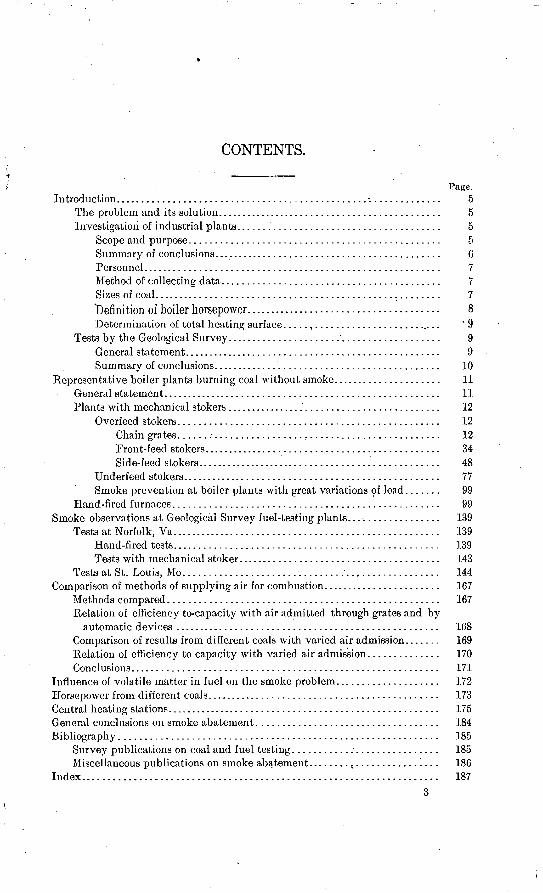
Page. FIGURE 1. Chain-grate stoker and Babcock & Wilcox boiler, with uptake in
rear.......................................................... 132. Chain-grate stoker and Stirling boiler..................:......... 143. Chain-grate stoker and Babcock & Wilcox boiler, with uptake in
front.......................................................... 154. Chain-grate stoker and return tubular boiler....................... 165. Front-feed stoker and Babcock & Wilcox boiler, usual setting...... 346. Front-feed stoker and Cahall boiler.............................. 357. Front-feed stoker and Heine boiler............................... 368. Front-feed stoker and Stirling boiler ............................. 379. Front-feed stoker and return tubular boiler........................ 38
10. Side-feed stoker in Dutch oven and Babcock & Wilcox boiler...... 4911. Side-feed stoker in Dutch oven and Cahall boiler................... 5012. Side-feed stoker and Heine boiler................................ 5113. Side-feed stoker in Dutch oven and Stirling boiler .................. 5114. Side-feed stoker and Stirling boiler.............................. 5215. Side-feed stoker and return tubular boiler, elevation.............. 5316. Side-feed stoker and return tubular boiler, cross section............. 5417. Underfeed stoker and Babcock & Wilcox boiler.................... 7818. Underfeed stoker and Heine boiler.............................. 7819. Underfeed stoker and Stirling boiler.............................. 7920. Underfeed stoker and return tubular boiler, elevation............. 8021. Underfeed stoker and return tubular boiler, cross section........... 8122. Underfeed stoker, plan.......................................... 8223. Underfeed stoker and Scotch marine boiler....................... 8324. Load and boiler-service chart of large power plant.................. 100
. 25. Automatic steam and air admission device and water-tube boiler... 10326. Automatic steam and air admission device and re turn tubular boiler. 10427. A. hand-fired furnace and Babcock & Wilcox boiler................ 10528. Down-draft furnace and Heine boiler............... ............. 10529. A hand-fired furnace and Babcock & Wilcox boiler, elevation ...... 10630. A hand-fired furnace, plan...................................... 10631. A hand-fired furnace, cross section................................ 10732. A hand-fired furnace and Scotch marine boiler, elevation .......... 11933. A hand-fired furnace, cross section............................... 12034. A hand-fired furnace and return tubular boiler.......... '. ........ 12135. A hand-fired furnace and retunrtubular boiler, elevation........... 12236. A hand-fired furnace, plan....................................... 12337. A hand-fired furnace and return tubular boiler, cross section....... 12438. Elevation and plan of setting of hand-fired Heine boiler............ 14039. Cross section of setting and plan of bridge wall of hand-fired Heine
boiler........................................................ 14140. Proportion of smoke-producing compounds given off at different
temperatures by several coals................................. 174
4
THE SMOKELESS COMBUSTION OF COAL IN BOILER PLANTS.
By D. T. RANDALL and H. W. WEEKS.
NOTE.
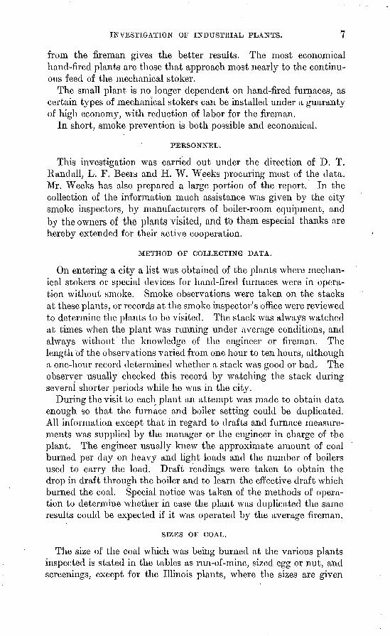
The drawings used as a basis for figure 1. (p. 13) and figure 3 (p. 15) of this report were supplied by Mr. A. Beraent, of Chicago, and'are slightly modified from the form in which they appeared in the Peabody Atlas, edited by Mr. Bement and published (Chicago, 1906) by the Peabody Coal Company.
The title line under figure 3, page 15, should read as follows: "FIGURE 3. Chain-grate stoker serving a tile-roof furnace designed by A. Bement, with a Babcock & Wilcox boiler."
Figure 27, page 105, represents a Dorrance furnace.The drawings used as a basis for figures 29 and 30 (p. 106) and figure 31
(p. 107) were reproduced from the Peabody Atlas.For the drawings used as a basis for other illustrations in this report the
authors are indebted to the kindness of the Westinghouse Machine Company, the Underfeed Stoker Company of America, the Green Engineering Company, the Murphy Iron Works, the Water Arch Furnace Company, the Detroit Stoker and Foundry Company, Charles J. Dorrance, the Burke Furnace Company, James McMillaii & Co., G. S. Calder, and the Hawley Down Draft Furnace Company.
tionable. Proper equipment, efficient labor, and intelligent super vision are the necessary factors.
INVESTIGATION OF INDUSTRIAL PLANTS.
SCOPE AND PURPOSE.
In the investigation of industrial establishments a study was made of the conditions in thirteen of the larger cities in Illinois, Indiana, Kentucky, Maryland, Michigan, Missouri, New York, Ohio, and Penn sylvania, between 400 and 500 plants being inspected. Sufficient information was collected to make the data from 284 plants of value
5
6 SMOKELESS COMBUSTION OF COAL.
for this report. In nearly every city visited coal was supplied from points both in and out of the State, so that although but nine States were visited, the facts ascertained apply to coals from a greater number.
The main purpose of the inspection was to obtain a better knowledge as to the influence on smoke production of furnace design and of the conditions under which combustion takes place.
SUMMARY OF CONCLUSIONS.
The results of this investigation are set forth in detail on later pages of this volume. The general conclusions to be drawn can be summa rized in a few paragraphs.
Smoke prevention is possible. There are many types of furnaces and stokers that are operated smokelessly.
Any one kind of apparatus is effective only if so set under boilers that the principles of combustion are respected. The value to the average purchaser of a manufacturer's requirement on this point lies in the fact that he is thus reasonably certain of good installation. A good stoker or furnace poorly set is of less value than a poor stoker or furnace well set. Good installation of furnace equipment is neces sary for smoke prevention.
Stokers or furnaces must be set so that combustion will be complete before the gases strike the heating surface of the^boiler. When partly burned gases at a temperature of, say, 2,500° F., strike the tubes of a boiler at, say, 350° F., combustion is necessarily hindered and may be entirely arrested. The length of time required for the gases to pass from the coal to the heating surface probably averages considerably less than one second, a fact which shows that the gases and air must
, be intimately mixed when large volumes of gas are distilled, as at times of hand firing, or the gas must be distilled uniformly, as in a mechanical stoker. By adding mixing structures to a mechanical stoker equipment both the amount of air required for combustion and the distance from the grates to the heating surface may be reduced for the same capacity developed. The necessary air supply can also be reduced by increasing the rate of combustion.
No one type of stoker is equally valuable for burning all kinds of coal. The plant which has an equipment properly designed to burn the cheapest coal available will evaporate water at the least cost.'
Although hand-fired furnaces can be operated without objection able smoke, the fireman is so variable a factor that the ultimate solu tion of the problem depends on the mechanical stoker in other words, the personal element must be eliminated. There is no hand- fired furnace from which, under average conditions, as good results can be obtained as from many different patterns of mechanical stoker, and of two equipments the one which will require the less attention
INVESTIGATION OF INDUSTRIAL PLANTS. 7
from the fireman gives the better results. The most economical hand-fired plants are those that approach most nearly to the continu ous feed of the mechanical stoker.
The small plant is no longer dependent on hand-fired furnaces, as certain types of mechanical stokers can be installed under a guaranty of high economy, with reduction of labor for the fireman.
In short, smoke prevention is both possible and economical.
PERSONNEL.
This investigation was carried out under the direction of D. T. Randall, L. F. Beers and H. W. Weeks procuring most of the data. Mr. Weeks has also prepared a large portion of the report. In the collection of the information much assistance was given by the city smoke inspectors, by manufacturers of boiler-room equipment, and by the owners of the plants visited, and to them especial thanks are hereby extended for their active cooperation.
METHOD OF COLLECTING DATA.
On entering a city a list was obtained of the plants where mechan ical stokers or special devices for hand-fired furnaces were in opera tion without smoke. Smoke observations were taken on the stacks at these plants, or records at the smoke inspector's office were reviewed to determine the plants to be visited. The stack was always watched at times when the plant was running under average conditions, and always without the knowledge of the engineer or fireman. The length of the observations varied from one hour to ten hours, although a one-hour record determined whether a stack was good or bad. The observer usually checked this record by watching the stack during several shorter periods while he was in the city.
During the visit to each plant an attempt was made to obtain data enough so that the furnace and boiler setting could be duplicated. All information except that in regard to drafts and furnace measure ments was supplied by the manager or the engineer in charge of the plant. The engineer usually knew the approximate amount of coal burned per day on heavy and light loads and the number of boilers used to carry the load. Draft readings were taken to obtain the drop in draft through the boiler and to learn the effective draft which burned the coal. Special notice was taken of the methods of opera tion to determine whether in case the plant was duplicated the same results could be expected if it was operated by the average fireman.
SIZES OF COAL.
The size of the coal which was being burned at the various plants inspected is stated in the tables as run-of-mine, sized egg or nut, and screenings, except for the Illinois plants, where the sizes are given
8 SMOKELESS COMBUSTION OF COAL.
as Nos. 1, 2, 3, 4, or 5. The standard for sizing coal is not uniform over the whole State of Illinois, but in Williamson County washed coal is passed over screens with round openings and is sized and num bered as follows:
No. 1, coal passing through 3-inch screen and over If-inch screen. No. 2, coal passing through If-inch screen and over 1-inch screen. No. 3, coal passing through 1-inch screen and over |-inch screen. No. 4, coal passing through f-inch' screen and over J-inch screen. No. 5, coal passing through |-inch screen.
About half the washeries in Illinois size coal according to the above scheme.
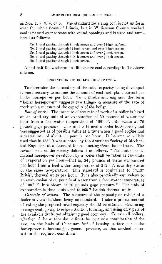
DEFINITION OF BOILER HORSEPOWER.
To determine the percentage of the rated capacity being developed it was necessary to assume the amount of coal each plant burned per boiler horsepower per hour. To a mechanical engineer the term "boiler horsepower" suggests two things a measure of the rate of work and a measure of the capacity of the boiler.
Rate of work. The measure of the rate of work of a boiler is based on an arbitrary unit of an evaporation of 30 pounds of water per hour from a feed-water temperation of 100° F. into steam at 70 pounds gage pressure. This unit is termed a boiler horsepower, and was suggested as of possible value at a time when a good engine had a water rate of about 30 pounds per hour. It became so widely used that in 1885 it was adopted by the American Society of Mechan ical Engineers as a standard for conducting steam-boiler trials. The revised code of the society defines it as follows: "The unit of com mercial horsepower developed by a boiler shall be taken as 34^ units of evaporation per hour that is, 34* pounds of water evaporated per hour from a feed-water temperature of 212° F. into dry steam of the same temperature. This standard is equivalent to 33,137 British thermal units per hour. It is also practically-equivalent to an evaporation of 30 pounds of water from a feed-water temperature of 100° F. into steam at 70 pounds gage pressure." The unit of evaporation is thus equivalent to 965.7 British thermal units.
Capacity of boilers. The measure of the capacity or rating of a boiler is variable,"there being no standard. Under a proper method of rating the proposed rated capacity should be attained when using average coal, giving average attention to firing, and using only part of the available draft, yet obtaining good economy. T.o rate all boilers, whether of the water-tube or fire-tube type or a combination of the two, on the basis of 10 square feet of heating surface per boiler horsepower is becoming a general practice, as this method comes within the required conditions.
TESTS BY THE GEOLOGICAL SURVEY. 9
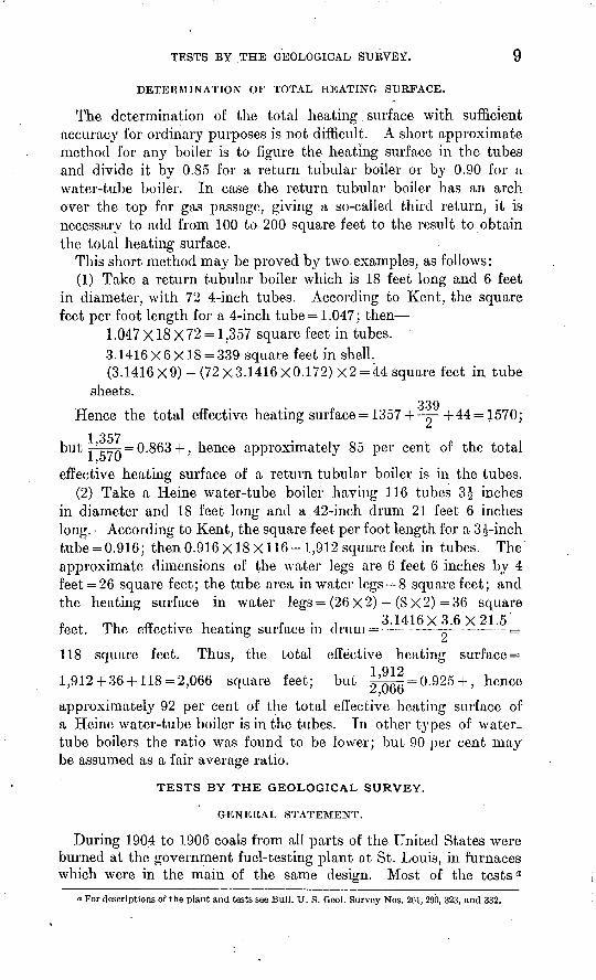
DETERMINATION OF TOTAL HEATING SURFACE.
The determination of the total heating. surface with sufficient accuracy for ordinary purposes is not difficult. A short approximate method for any boiler is to figure the heating surface in the tubes and divide it by 0.85 for a return tubular boiler or by 0.90 for a water-tube boiler. In case the return tubular boiler has an arch over the top for gas passage, giving a so-called third return, it is necessary to add from 100 to 200 square feet to the result to obtain the total heating surface.
This short method may be proved by two examples, as follows:(1) Take a return tubular boiler which is 18 feet long and 6 feet
in diameter, with 72 4-inch tubes. According to Kent, the square feet per foot length for a 4-inch tube = 1.047; then
1.047 X18 X72 = 1,357 square feet in tubes. .3.1416X6X18 = 339 square feet in shell.(3.1416 X9) -(72X3.1416 X0.172) X2 = 44 square feet in tube
sheets.339 Hence the total effective heating surf ace = 1357+ ^- +44 = 1570;
1 357but '-n = 0.863 + , hence approximately 85 per cent of the total
1 ,o i (Jeffective heating surface of a return tubular boiler is in the tubes.
(2) Take a Heine water-tube boiler having 116 tubes 3$ inches in diameter and 18 feet long and a 42-inch drum 21 feet 6 inches long. According to Kent, the square feet per foot length for a 3^-inch tube = 0.916; then 0.916x18x116 = 1,912 square feet in tubes. The approximate dimensions of the water legs are 6 feet 6 inches by 4 feet = 26 square feet; the tube area in water legs = 8 square feet; and the heating surface in water legs = (26 X 2) (8 X 2) = 36 squaref 4. rm, ff .- u * f i 3.1416X3.6X21.5 reet. The effective heating suri ace m drum= - ^-- =
£
118 square feet. Thus, the total effective heating surface =
1,912 + 36 + 118 = 2,066 square feet; but ^| = 0 - 925 + > lience
approximately 92 per cent of the total effective heating surface of a Heine water-tube boiler is in the tubes. In other types of water- tube boilers the ratio was found to be lower; but 90 per cent may be assumed as a fair average ratio.
TESTS BY THE GEOLOGICAL SURVEY.
GENERAL STATEMENT.
During 1904 to 1906 coals from all parts of the, United States were burned at the government fuel-testing plant at St. Louis, in furnaces which were in the main of the same design. Most of the tests a
a For descriptions of the plant and tests see Bull. U.S. Geol. Survey Nos. 201, 290, 323, and 332.
10 SMOKELESS COMBUSTION OF COAL.
were made on a hand-fired furnace under a Heine water-tube boiler. The lower row of tubes of the boiler supported a tile roof for the furnace, giving the gases from the coal a travel of about 12 feet before coming into contact with the boiler surface. This furnace is more favorable to complete combustion than those installed in the average plant. A number of coals were burned in this furnace with little or no smoke, but many coals could not be burned without making smoke that would violate a reasonable city ordinance when the boiler was run at or above its rated capacity. Boilers having furnaces installed under less favorable conditions will give off more smoke.
In 1907 the steaming section of the St. Louis plant was moved to Norfolk, Va., where subsequent tests of this nature have been made. The plant at Norfolk was equipped with two furnaces one fired by hand and the other by a mechanical stoker. Both were operated under Heine boilers.
In the course of the steaming tests at St. Louis and Norfolk some special smoke tests were made and the influence of various factors in smoke production was noted. As the tests were made as far as possible under standard conditions, with a minimum of variation in boiler-room labor, the results bring out the importance of other fac tors such as character of fuel and furnace design./
SUMMARY OF CONCLUSIONS.
A detailed discussion of these tests, with numerous tables, is presented on pages 139-167 of this volume. A brief summary of the general conclusions is as follows:
A well-designed and operated furnace will burn many coals with out smoke up to a certain number of. pounds per hour, the rate vary ing with different coals, depending on their chemical composition. If more than this amount is burned, the efficiency will decrease and smoke will be made, owing to the lack of furnace capacity to supply air and mix gases.
High volatile matter in the coal gives low efficiency, and vice versa. The highest efficiency was obtained when the furnace was run at low capacity. When the furnace was forced the efficiency decreased.
With a hand-fired furnace the best results were obtained when firing was done most frequently, with the smallest charge.
Small sizes of coal burned with less smoke than large sizes, but developed lower capacities.
Peat, lignite, and subbituminous coal burned readily in the type of tile-roofed furnace used and developed the rated capacity with practically no smoke.
Coals which smoked badly gave efficiencies 3 to 5 per cent lower than the coals burning with little smoke.
Briquets were found to be an excellent form for using slack coal in a hand-fired plant. They can be burned at a fairly rapid rate
PLANTS BURNING COAL WITHOUT SMOKE. 11
of combustion with good efficiency and with practically no smoke. High-volatile coals when briquetted are perhaps as valuable as low- volatile coals when not briquetted.
A comparison of tests on the same coal washed and unwashed showed that under the same conditions the washed coal burned much more rapidly than the raw coal, thus developing high rated capacities. In the average hand-fired furnace washed coal burns with lower efficiency and makes more smoke than raw coal. How ever, washed coal offers a means of running at high capacity, with good efficiency, in a well-designed furnace.
Forced draft did not burn coal any more efficiently than natural draft. It supplied enough air for high rates of co.mbustion, but as the capacity of the boiler increased the efficiency decreased and the percentage of black smoke increased.
Most coals that do not clinker excessively can be burned with lto 5 per cent greater efficiency and with a smaller percentage of black smoke on a rocking grate than on a flat grate.
Air admitted freely at firing and for a short period thereafter increases efficiency and reduces smoke.
As the CO in the flue gas increases the black smoke increases; the percentage of CO in the flue gas is therefore, in general, a good guide to efficient operation. However, owing to the difficulty of deter mining this factor, combustion can not be°regulated by it.
The simplest guide to good operation is pounds of coal burned per square, foot of grate surface per hour.
REPRESENTATIVE BOILER PLANTS BURNING COAL WITHOUT SMOKE.
GENERAL STATEMENT.
Bulletin 334, the preliminary report on smokeless combustion, takes up information collected and conclusions reached while assem bling the data summarized in the present report and sets forth many facts of general interest that are not discussed in the following pages. This paper deals especially with the equipment of particular boiler plants which were found to be burning coal without smoke, and with the essentials of good furnace design. A brief summary of the general conclusions is presented on pages 171-172. The details on which these conclusions are based are set forth in the following pages.
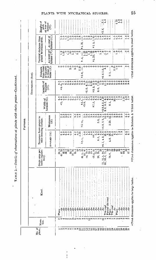
For the sake of clearness the important features of the equipment of the boiler plants visited are stated in tabular form.
Although there were very few plants at which' all the items covered by the tables could be ascertained, the more essential details those bearing directly on the subject of smoke prevention were obtained at nearly every plant. The density of the smoke is stated on a percentage basis, 0 meaning a clean stack and 100 per cent meaning dense black smoke.
12 SMOKELESS COMBUSTION OP COAL.
In the tables the furnace dimensions are checked by letters from A to H, which refer to the dimensions indicated by the corresponding letters on the illustrations showing typical installations of furnaces under boilers of various types. These illustrations are intended to show especially the average and the minimum travel of the gases from the fire to the first cooling surface in the boiler, the height of the furnace, and the length of the coking arch.
In the- illustrations some makes of boilers appear more frequently than others. This does not imply any preference for certain models. Boilers of widely differing patterns have shown equal efficiency in steaming trials, and it is coming to be a general belief that among the types of boilers ordinarily used at power plants peculiarities of tube arrangement count for less than proper furnace design. This report of what has been done to effect smokeless combustion emphasizes the importance of furnace design and management and makes no com parisons between boilers. The illustrations show details of furnace construction and the importance of certain features.
For convenience of treatment the following order is adopted in discussing the equipment of the various plants:Mechanical stoker plants,
(a) Overfeed stokers.1. Chain grates.2. Front feed.3. Side feed.
(6) Underfeed stokers.
Hand-fired plants.(a) Furnaces under water-tube boilers. (6) Furnaces under return tubular
boilers. " 1. Down-draft furnaces.
2. Furnaces using steam, jets.3. Furnaces with miscellaneous
equipment.
PLANTS WITH MECHANICAL STOKERS.
The use of mechanical devices for firing coal reduces labor in the boiler ropm, but the main object of mechanical stoking is to feed a steady, regulated supply of coal and air to the furnace. The ad vantages of feeding a fire steadily were seen in the early days of steam engineering, but defects in design or faulty installation and management kept mechanical stokers from coming into general use. Within the last decade, However, their use has greatly increased. They are of two general types overfeed and underfeed.
OVERFEED STOKERS.
CHAIN GRATES.
GENERAL DISCUSSION.
The earliest mechanical stoker was of the treadmill type, so called because the arrangement of the grate bars as a traveling belt resembled the apron of a treadmill. It was patented in England as far back as 1841. Improved in details of construction, this.type, under the name chain grate, has come into extensive use in this country. The coal is fed from a hopper, which extends the entire width of the grate
PLANTS WITH MECHANICAL STOKERS. 13
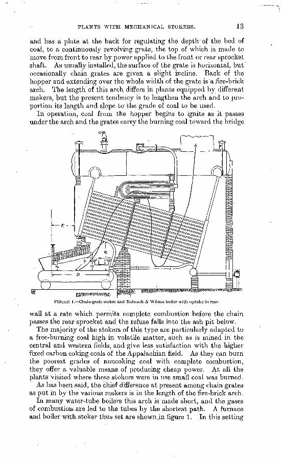
and has a plate at the back for regulating the depth of the bed of coal, to a continuously revolving grate, the top of which is made to move from front to rear by power applied to the front or rear sprocket shaft. As usually installed, the surface of the grate is horizontal, but occasionally chain grates are given a slight incline. Back of the hopper and extending over the whole width of the grate is a fire-brick arch. The length of this arch differs in plants equipped by different makers, but the present tendency is to lengthen the arch and to pro portion its length and slope to the grade of coal to be used.
In operation, coal from the hopper begins to ignite as it passes under the arch and the grates carry the burning coal toward the bridge
FIGURE 1. Chain-grate stoker and Babcock & Wilcox boiler with uptake in rear.
wall at a rate which permits complete combustion before the chain passes the rear sprocket and the refuse falls into the ash pit below.
The majority of the stokers of this type are particularly adapted to a free-burning coal high, in volatile matter, such as is mined in the central and western fields, and give less satisfaction with the higher fixed carbon coking coals of the Appalachian field. As they can burn the poorest grades of noncoking coal with complete combustion, they offer a valuable means of producing cheap power. At all the plants visited where these stokers were in use small coal was burned.
As has been said, the chief difference at present among chain grates as put in by the various makers is in the length of the fire-brick arch.
In many water-tube boilers this arch is made short, and the gases of combustion-are led to the tubes by the shortest path. A furnace and boiler with stoker thus set are shown ,in figure 1. In this setting
14 SMOKELESS COMBUSTION OF COAL.
the distance of travel for the gases from the grates to the tube heating surface, indicated by the line B, is reduced to a minimum and the average distance from the fire to the first cooling surface encountered (A) approaches a minimum.
This type of installation is common in the Middle West, where a higher proportion of chain grates is in use than in any other section of the United States, but the short arch and the brief travel of the gases to the first tube heating surface are features unfavorable to smokeless combustion.
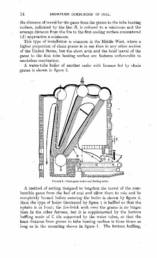
A water-tube boiler of another make with furnace fed by chain grates is shown in figure 2.
FIGURE 2. Chain-grate stoker and Stirling boiler.-
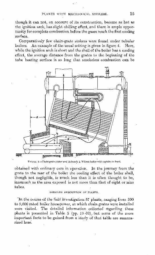
A method of setting designed to lengthen the travel of the com bustible gases from the bed of coal and allow them to mix and be completely burned before entering the boiler is shown by figure 3. Here the type of boiler illustrated by figure 1 is baffled, so that the uptake is'in front; the fire-brick arch over the grates is.no longer than in the other furnace, but it is supplemented by the bottom baffling made of C tile supported by the water tubes, so that the least distance from grates to tube heating surface is three times as long as in the mounting shown in figure 1. The bottom baffling,
PLANTS WITH MECHANICAL STOKERS. 15
though it can not, on account of its construction, become as hot as the ignition arch, has slight chilling effect, and there is ample oppor tunity for complete combustion before the gases reach the first cooling surface.
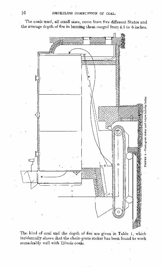
Comparatively few chain-grate stokers were found under tubular boilers. An example of the usual setting is given in figure 4. Here, while the ignition arch is short and the shell of the boiler has a cooling effect, the average distance from the grates to the beginning of the tube heating surface is so long that smokeless combustion can be
FIGURE 3. Chain-grate stoker and Babcock & Wilcox boiler with uptake in front.
obtained with ordinary care in operation. In the journey from the grate to the rear of the boiler the cooling effect of the boiler shell, though not negligible, is much less than it is often thought to be, inasmuch as the area exposed is not more than that of eight or nine tubes.
DETAILED DESCRIPTION OF PLANTS.
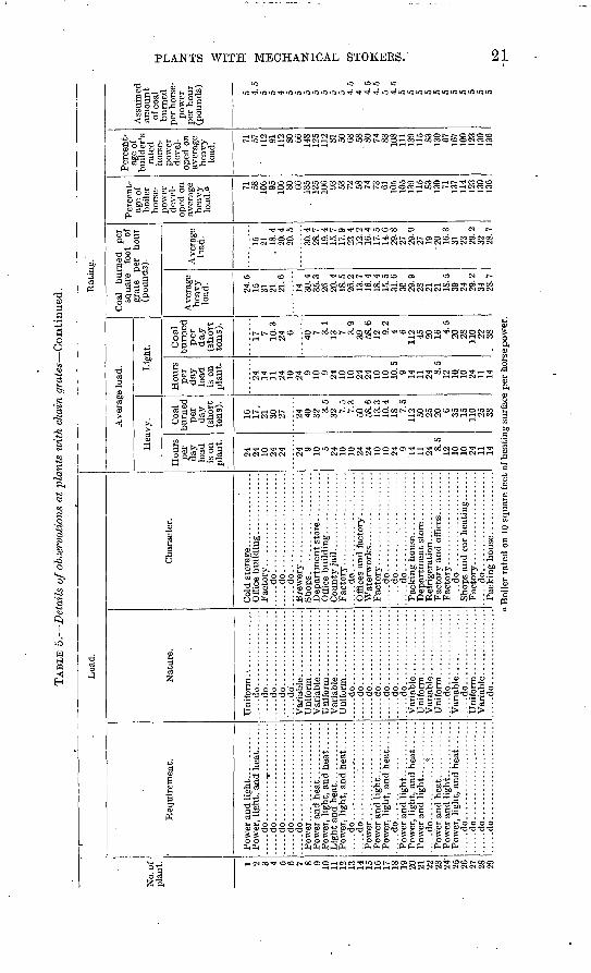
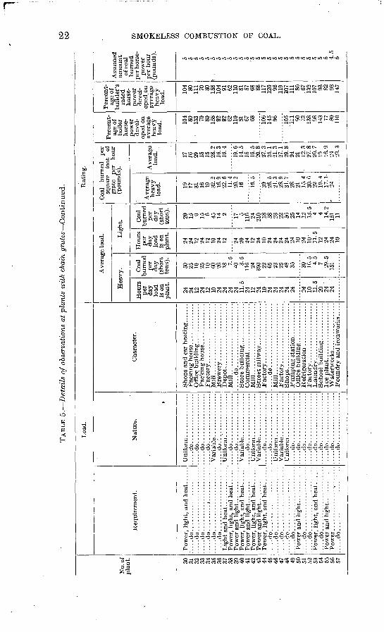
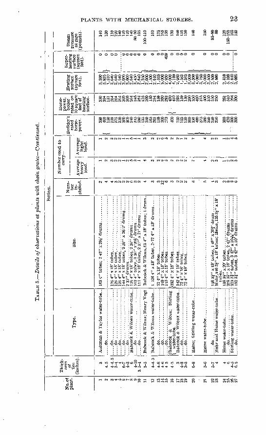
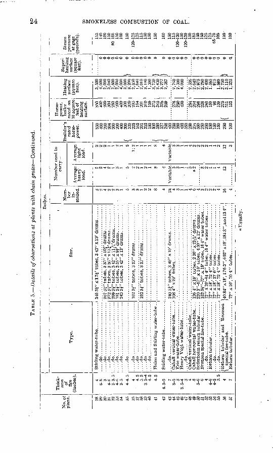
"In the course of the field investigation 57 plants, ranging from 300 to 9,600 rated boiler horsepower, at which chain grates were installed were visited. The detailed information collected regarding these plants is presented in Table 5 (pp. 19-32), but some of the more important facts to be gained from a study of that table are summa rized here.
16 SMOKELESS COMBUSTION OF COAL.
The coals used, all small sizes, came from five different States and the average depth of fire in burning them ranged from 4.5 to 6 inches.
The kind of coal and the depth of fire are given in Table 1, which incidentally shows that the chain-grate stoker has been found to work remarkably well with Illinois coals.
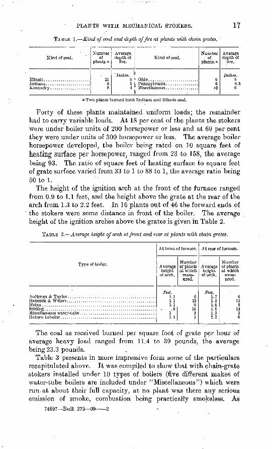
PLANTS WITH MECHANICAL STOKEES. 17
TABLE 1. Kind of coal and depth of fire at plants with chain grates.
Kind of coal.
Illinois.......................
Number of
plants, a
2188
Average depth of
tore.
' Inches. 554
Kind of coal.
Ohio.........................
Number of
plants.o
66
10
Average depth of
lire.
Inches. 54.56
a Two plants burned both Indiana and Illinois coal.
Forty of these plants maintained uniform loads; the remainder had to carry variable loads. At 18 per cent of the plants the stokers were under boiler units of 200 horsepower or less and at 69 per cent they were under units of 300 horsepower or less. The average boiler horsepower developed, the boiler being rated on 10 square feet of heating surface per horsepower, ranged from 23 to 158, the average being 93. The ratio of square feet of heating surface to square feet of grate surface varied from 33 to 1 to 88 to 1, the average ratio being 50 to 1.
The height of the ignition arch at the front of the furnace ranged from 0.9 to 1.1 feet, and the height above the grate at the rear of the arch from 1.3 to 2.2 feet. In 16 plants out of 46 the forward ends of the stokers were some distance in front of the boiler. The average height of the ignition arches above the grates is given in Table 2.
TABLE 2. Average height of arch at front and rear at plants with chain grates.
Type of boiler.
Stirling ........................................................
At front of furnace.
Average height
of arch.
Feet. 1.1 1.1 1.1 .9
1 1.1
Number of plants at which
meas ured.
6 13 6
16 3 5
At rear of furnace.
Average height of arch.
Feet. 1.7 1.5 1.6 1.5 1.3 2.2
Number of plants at which
meas ured.
6 13
5 14 3 6
The coal as received burned per square foot of grate per hour of average heavy load ranged from 11.4 to 39 pounds, the average being 23.3 pounds.
Table 3 presents in more impressive form some of the particulars recapitulated above. It was compiled to show that with chain-grate stokers installed under 10 types of boilers (five different makes of water-tube boilers are included under "Miscellaneous") which were run. at about their full capacity, at no plant was there any serious emission of smoke, combustion being practically smokeless. As
74897 Bull. 373 09 2
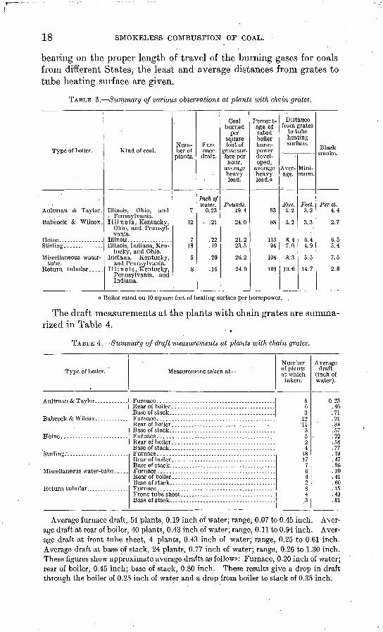
18 SMOKELESS COMBUSTION OF COAL.
bearing on the proper length of travel of the burning gases for coals from different States, the least and average distances from grates to tube heating surface are given.
TABLE 3. Summary of various observations at plants with chain grates.
Type of boiler.
Aultman & Taylor.
Babcock & Wilcox.
Stirling..............
Miscellaneous water- tube.
Kind of coal.
Illinois, Ohio, and . Pennsylvania. Illinois, Kentucky,
Ohio, and Pennsyl vania.
Illinois, Indiana, Ken tucky, and Ohio.
Indiana, Kentucky, and Pennsylvania.
Illinois, Kentucky, Pennsylvania, and Indiana.
Num ber of plants.
7
12
7 18
5
8
Fur nace draft.
Inch of water.
0.23
.21
.22
.19
.20
.15
Coal burned
per square foot of
grate sur face per hour,
average heavy load.
Pounds. 19.4
24.0
21.2 23.5
20.2
24.9
Percent age of rated boiler horse power devel oped,
average heavy load. a
83
88
113 94
104
108
Distance from grates
to tube heating surface.
Aver age.
Feet. 5.2
5.2
8.4 7.0
8.3
19.0
Mini mum.
Feet. 3.2
3.3
6.4 4.9
5.5
14.7
Black smoke.
Per ct. 4.4
2.7
0.5 5.4
7.5
2.8
a Boiler rated on 10 square feet of heating surface perhorsepower.
The draft measurements at the plants with chain grates are summa rized in Table 4.
TABLE 4. Summary of draft measurements at plants luith chain grates.
Type of boiler. Measurement taken at
Base of stack. .....................................Furnace ..........................................
Furnace ..........................................
Number of plants at which
taken.
563
12
5524
1817
7G42843
Average draft
(inch of water).
0.23.46.71.21.34.57.22.58.77.19.47.96.20.41.60.15.43.81
Average furnace draft, 54 plants, 0.19 inch of water; range, 0.07 to 0.45 inch. Aver age draft at rear of boiler, 40 plants, 0.43 inch of water; range, 0.11 to 0.94 inch. Aver age draft at front tube sheet, 4 plants, 0.43 inch of water; range, 0.25 to 0.61 inch. Average draft at base of stack, 24 plants, 0.77 inch of water; range, 0.26 to 1.30 inch. These figures show approximate average drafts as follows: Furnace, 0.20 inch of water; rear of boiler, 0.45 inch; base of stack, 0.80 inch. These results give a drop in draft through the boiler of 0.25 inch of water and a drop from boiler to stack of 0.35 inch.
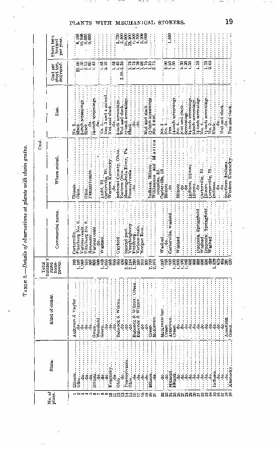
TAB
LE 5
. D
etai
ls o
f obs
erva
tion
s at
pla
nts
wit
h ch
ain
grat
es.
No.
of
plan
t. 1 2 3 4 5 6 7 8 9 10
11
12
13
14
15
16
17
18
19
20
21 22
23
24
25
26
27
28
29
30
31
32
33
34
35
36
37
38
39
Sta
te.
Oh
io..
....
....
....
....
.....d
o................
.....d
o................
.....d
o................
.....d
o................
.....d
o................
.....d
o................
.....d
o................
.....d
o................
.....d
o................
.....d
o................
.....d
o................
.....d
o......
..........
.....d
o................
.....d
o................
.....d
o................
Illin
ois.
...
....
....
....
.....d
o................
.....d
o................
.....d
o................
.....d
o................
.....d
o................
.....d
o......
..........
.....d
o................
.....d
o................
.....d
o......
....
....
..
.....d
o......
..........
.....d
o......
..........
.....d
o................
Ken
tuck
y..
....
....
...
Kin
d of
sto
ker.
.....d
o......................
.....d
o......................
....
.do
....
....
....
....
....
....
...d
o..
....
....
....
....
....
.....d
o......................
.....d
o......................
.....d
o......................
.....d
o......................
.....d
o......................
.....d
o......................
Bab
cock
& W
ilcox
; G
reen
. .
.....d
o......................
.....d
o......................
McK
enzi
e ba
r. ..............
Am
eric
an
.....d
o......................
.....d
o......................
.....d
o......................
.....d
o......................
.....d
o......................
....
.do
....
....
....
....
....
....
...d
o..
....
....
....
....
....
....
.do
....
....
....
....
....
....
...d
o..
....
....
....
....
....
.....d
o......................
....
.do
....
....
....
....
....
....
...d
o..
....
....
....
....
....
Gre
en..
....
....
....
....
....
.
Tot
al
buil
der's
ra
ted
hors
e
pow
er.
700
1,10
0 1,
000
825
500
600
600
1,44
0
500
655
595
450
3,60
0 2,
184
1,20
0 50
0 31
0 30
0 2,
700
1,00
0 75
0 60
0 1,
260
1,80
0 .
1,50
0 1,
050
800
800
608
600
600
400
1,52
067
5 49
5 20
1 62
0
Coa
l.
Com
mer
cial
nam
e.
Pit
tsbu
rg N
o. S
. ...
....
.
.....d
o..................
Wash
ed..
....
....
....
...
.....d
o..................
Duq
uoin
; S
prin
gfie
ld .
. .
Whe
re m
ined
.
Ohio
................. .......
.L
add,
11
1..
....
....
....
....
..C
arte
rvill
e, 1
11...
.... ..
....
..
.....d
o.... ..................
Bel
mon
t Cou
nty,
Ohio
.. ....
Mon
onga
hela
Riv
er,
Pa.
....
.....d
o......................
Will
iam
son
and
Mari
on
coun
ties,
111
. C
arte
rvill
e, 1
11...
.. ..........
....
.do
....
....
....
....
....
..
.....d
o......................
.....d
o......................
Indi
ana;
Illi
nois
...
....
....
.
....
.do
....
....
....
....
....
...
.....d
o......................
.....d
o......................
Wes
tern
Ken
tuck
y ..
....
....
Size
.
No
. 3
....
...............
Sla
ck..
....
....
....
....
Sla
ck..
....
....
....
....
....
.do
....
....
....
....
.IJ
-inc
h sc
reen
ings
. ...
....
...d
o..
....
....
....
...
Nos
. 3
and
4 m
ixed
.....
....
.do
....
....
....
....
.f-
inch
scr
eeni
ngs .......
IJ-i
nch
scre
enin
gs ...
...
Sla
ck..................
....
.do
....
....
....
....
...
...d
o..
....
....
....
...
Nut
and
sla
ck. .
........
No.
3 n
ut.
....
....
....
.
No.
3..
....
....
....
....
. N
o. 4
...................
Pea
. ...................
No.
4...................
IJ-i
nch
scre
enin
gs. .
....
li-i
nch
scre
enin
gs ..
....
No.
4...................
No.
2...................
Sla
ck..................
....
.do
....
....
....
....
.N
ut a
nd s
lack
. .........
....
.do
....
....
....
....
.P
ea a
nd s
lack
....
....
..
Cos
t per
sh
ort
ton,
de
liver
ed.
S2.0
0 1.
50
2.15
1.
80
1.45
1.55
2.
10
1.58
1.
40
2. 0
5-2.
35
1.75
1.
75
1.70
1.
60
1.75
1.
35
2.75
""""
3." 6
6'1.
80
1.60
2.30
1.
20
1.35
1.25
1.25
2.
65
Sho
rt t
ons
burn
ed
per
year
.
6,18
8 10
,950
6,
000
9,00
0
3,72
0 2,
500
' 16
,000
23
,360
6,
500
4,70
0 2,
500
3,00
0
1,80
0
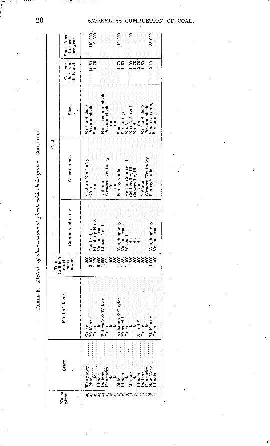
TAB
LE 5
. D
etail
s of o
bser
vati
ons
at p
lant
s w
ith
chai
n gra
tes
Con
tinu
ed.
No.
of
pla
nt. 40 42 40 AC
.
47 AQ 49 ^ 51 CO
CO S4 55 56 57
Sta
te.
Ohio
..................
.....d
o......
....
....
..
.....d
o........
....
....
....
..d
o..
....
..........
.....d
o........
....
....
Kin
d o
f st
oker
.
.....d
o......................
Gre
en.....d
o......................
.....d
o......................
.....d
o......................
.....d
o......................
S. a
ndS
....................
.....d
o......................
Tot
al
rate
d ho
rse
po
wer
.
300
3,40
01,
170
9, C
OO1,
000
924
400
350
1,00
01,
584
1,40
075
0w
>30
030
060
04,
000
400
Com
mer
cial
nam
e.
.....d
o..................
.....d
o..................
.....d
o..................
Coa
l.
Whe
re m
ined
.
.....d
o.............:
........
.....d
o......................
.....d
o......................
Col
lins
vill
e, 1
11
....
....
....
..
.....d
o......................
Size
.
.....d
o.................
.....d
o.................
Sla
ck..................
No.
3. .
.................
Nos
. 2,
3,
and
4.........
No.
4..........
....
....
......d
o.................
Cos
t per
sh
ort
ton,
de
live
red.
SI. 8
01.
75
1.70
1.50
1.90
1 75
2.75
1.60
2.10
Sho
rt t
ons
burn
ed
per
year
.
110,
000
9,60
0
19, 2
00
4,40
0
55,0
00
TAB
LE 5
. D
etai
ls o
f obs
erva
tion
s at
pla
nts
wit
h ch
ain
gra
tes
Conti
nued
.
No.
of
pla
nt. 1 2 3 4 5 6 7 8 9 10
11
12
13
14
15
16
17
18
19
20
21
22
23
24
' 25
26
27
28
29
Loa
d.
Req
uire
men
t.
Pow
er a
nd l
ight
. ............
.....d
o........
.. ...........
....
.do
....
....
....
....
....
.......d
o........
....
....
....
....
...d
o..
....
....
....
....
....
Pow
er a
nd h
eat .
............
....
.do..
....
................
.....d
o.. ...
....
....
....
....
.
....
.do
....
....
....
.*..
....
...
Pow
er a
nd
lig
ht.
. ...........
....
.do
....
....
....
....
....
......d
o........
....
....
....
....
...d
o..
....
...............
Nat
ure.
Uni
form
.-. .
....
....
....
.....d
o.................
....do.................
....do.................
....
.do..
....
....
....
...
......do
1.................
Vari
able
...............
.....d
o.................
.....d
o.................
.....d
o.................
.....d
o.................
.....d
o.................
....
.do..
....
....
....
...
.....d
o.................
.....d
o.................
.....d
o.................
....
.do
....
....
....
....
.
Cha
ract
er.
....
.do
....
....
....
....
....
....
...d
o..
....
....
....
....
....
....
.do..
....
....
....
....
....
Off
ice
buil
ding
...
....
....
...
...
.do... ............:.
.....
....
.do..
....
....
....
....
....
....
.do
....
....
....
....
....
....
...d
o..
....
....
....
....
....
Dep
artm
ent
stor
e. ...
....
...
Fac
tory
. ...
....
....
....
....
.
Pac
kin
g h
ouse
..............
Rat
ing.
Ave
rage
loa
d.
Hea
vy.
Hou
rs
per
da
y lo
ad
is o
n p
lan
t.
24
24
10 24
24 24 9 10 5 24
10
10
24
24
10
10
24 9 14
11
24 8.5
12
10
10
24
11
14
Coa
l b
urn
ed
per
day
(s
hort
to
ns).
16
17.
21
30
27 24
40
32 3.5
32 7.5
7.3
50
58.6
13
.3
10.4
18
7.5
112 50
25
20 6 35
15
110 25
38
Lig
ht.
Ho
urs
p
er
day
lo
ad
is o
n p
lan
t.
24
14
11
24
10
24 9 10 9 24
10
10
24
24
10
10
10.5
9 14
11
24
8.5
12
10
10
24
11
14
Coal
burn
ed
per
day
(s
hort
to
ns)
.
17 7 10.3
24
6 40 7
' 3.
1 13
7 3.9
39
58.6
12
9.2
4 6 11
2 45
20
16 4.5
20
28
110 22
.
38
Coa
l burn
ed
per
squa
re
foot
of
gr
ate
per
hour
(p
ound
s).
Ave
rage
h
eav
y
load
.
24.5
15
31
21
21
.6
14
30.4
35
.3
26
20.4
18
.5
26.2
13
.7
16.4
18
.4
15.5
31
.6
3C
29.9
28
21
21
18
.5
39
24
29.2
34
28
.7
Ave
rage
H
ad.
15 21
. 18
.4
20.4
20
.5
30.4
28
.7
19.4
15
.7
17.9
23
.4
12.2
16
.4
17.5
14
.6
29.8
27
29
.9
27
19
20
16.3
31
23
29
.2
32
23.7
Per
cent
ag
e of
bo
iler
ho
rse
po
wer
de
vel
op
ed o
n av
erag
e hea
vy
load
." 71
58
106 95
10
6 80
66
135
125
106 93
53
72
58
74
73
61
105
105
139
115 S3
130 71
137
114
123
130
136
Per
cent
ag
e of
bu
ilde
r's
rate
d ho
rse
po
wer
de
vel
op
ed o
n av
erag
e hea
vy
load
. 71
57
112 91
112 80
66
148
125
112 81
50
68
58
"80 74
83
10
8 11
1 13
9 11
5 83
. 13
0 67
167
100
123
130
136
Ass
umed
am
ount
of c
oal
bu
rned
p
er h
orse
po
wer
per
ho
ur
(pou
nds) 5 4.
5 5 5 4 5 5 5 5 5 5 5 4.
5 4 4.
5 4.
5 5 4.
5 5 5 5 5 5 5 5 5 5 5 5
fel
o w > 52} I I o
>
f 02 H
O I
' Boi
ler
rate
d o
n 10
squ
are
feet
of h
eati
ng s
urfa
ce p
er h
orse
pow
er.
TAB
LE 5
. D
etai
ls o
f ob
serv
atio
ns a
t pl
ants
wit
h ch
ain
gra
tes
Conti
nued
.to
to
No.
of
plan
t. 30
31
32
33
34
35
36
37
38
39
40
41
42
43
44
45
46
47
48
49
50
51
52
53
54
55
50
' 57
Loa
d.
Req
uire
men
t.
....
.do
....
....
....
....
....
....
...d
o..
....
....
....
....
....
....
.do..
....................
....
.do..
....................
....
.do
....
....
....
....
....
....
...d
o..
....
....
....
....
....
.....d
o......................
....
.do
. ..
....
....
....
....
...
....
.do
....
....
....
....
....
..
.....d
o......................
Nat
ure.
»
....
.do..
....
....
....
...
....
.do..
....
....
....
...
.....d
o.................
....
.do
....
....
....
....
.
.....d
o.:
...............
....
.do..
....
....
....
...
....
.do
....
....
....
....
..
.....d
o.................
.....d
o.................
.....d
o.................
.....d
o.................
.....d
o.................
....
.do..
....
....
....
...
....
.do..
....
....
....
...
....
.do..
....
....
....
...
.....d
o.................
.....d
o.................
.....d
o.................
....
.do
....
....
....
....
.
Cha
ract
er.
Sho
ps a
nd c
ar h
eati
ng. .
....
.P
acki
ng h
ouse
..............
Off
ice
buil
ding
. . ............
Pac
king
hou
se ..............
Fac
tory
. ....................
Mil
l.........................
Bre
wer
y ..
....
....
....
....
..D
ep
ot.
......................
Mil
l. ........................
.....d
o......................
Sto
re b
uild
ing.
...
....
....
...
Com
mer
cial
.................
Mil
l.........................
. . .
..do......................
Mil
l.........................
Fac
tory
. ...
....
....
....
....
.S
hops.......................
Pum
ping
sta
tion
. ...
....
....
Off
ice
buil
ding
..............
Ref
rige
rati
on ...............
Fac
tory
. .....................
Lau
nd
ry. .
.................'.
Sch
ool
buil
ding
. ...
....
....
.Ic
e pl
ant.
...................
Wat
erw
orks
. . ...
....
....
....
Foundry
and
iro
nwor
ks..
. . .
Rat
ing.
Ave
rage
load
.
Hea
vy.
Hou
rs
per
day
load
is
on
plan
t.
24
24
12
24
12
10
24
24
24
24
11.5
24
12
24
10
24
24
24
24
24 24
10
11
.5
20
24
24
Coa
l bu
rned
pe
r da
y (s
hort
to
ns).
50
25
10
25
10
60
26
18 7.5
40 3.5
116 24
350 22
65
23
25
48
35 30
16.5
4.
5 7 29
.5
151
Lig
ht.
Hou
rs
per
day
load
is
on
plan
t.
24
24
12
24
12
10
24
12 24
20
24
12
24
10
24
24
24
24
24
10
24 10-
11.5
12
24
24
10
Coa
l bu
rned
pe
r da
y (s
hort
to
ns).
20
15 9 15 6 45
14 2 17 5
116 24
210 18
58
23
22
56
25
14
12
13
.5
4 4 14.2
15
1 11
Coa
l bu
rned
pe
r sq
uare
fo
ot
of
grat
e pe
r ho
ur
(pou
nds)
.
Ave
rage
he
avy
load
.
19
17
31
16
19
32.2
16
.9
22.6
11
.4
20.2
16 16
.5
30
26.5
21
.3
28.9
31
.7
28
21
15.4
30
.6
22
19.4
17
.1-
24
Ave
rage
lo
ad.
17
16
29
15
15
28.2
16
.3
16.4
19.6
14
.5
15
16.5
20
.8
27.3
25
.1
21.3
27
.1
29.8
24
21
12
.3
27.8
20
.7
19
16.9
24
23
.3
Per
cent
ag
e of
bo
iler
hors
e
pow
er
deve
l
oped
on
aver
age
heav
y lo
ad. 10
4 80
133 70
80
15
8 92
92
62
110 81
67
68 ioe>
145 96 105
'111
90
73
13
8 98
143 77
- 80
11
0
Per
cent
ag
e of
bu
ilde
r's
rate
d ho
rse
po
wer
de
vel
op
ed o
n av
erag
e he
avy
load
. 104 80
111 70
80
15
8 10
4 91
62
110 81
57
68
88
117
120 96
119
107
111 80
.6
7 13
2 10
7 93
82
93
147
Ass
umed
am
ount
of
coa
l bu
rned
pe
r hor
se
pow
er
per
hour
(p
ound
s).
5 5 5 5 5 .
. 5 5 5 5 5 5 5 5 5 5 5 5 5 5 5 5 5 5 5 5 5 4.5
5
TAB
LE 5
. D
etai
ls o
f ob
serv
atio
ns a
t pl
ants
wit
h ch
ain
grat
es C
on
tin
ued
.
No.
of
plan
t. 1 2 3 4 .
5 6 7 8 9 10 11 12 13
14
15
16 17
18
19 20 21 22
23 24
25
26
27
Thic
k
nes
s of
'fi
re
(in
ches
).
3 4.
54
-4.5
3-
4 4 6-
7 4-
5 6 4-
10
3.5
-4 3-5
4-4.
54-
8 4-
6 4-
54-
5 3 4-
S
3-5
6-8
3-6
5-7 4 4 6
4-5
6.5
Boil
ers.
;
Ty
pe.
Ault
man
& T
aylo
r w
ater
-tube.
. ...:
.do... .......................
....
.do
....
....
....
....
....
....
....
...d
o..
....
....
....
....
....
....
....
.do
....
....
....
....
....
....
......
.do
....
....
....
....
....
....
......
.do
....
....
....
....
....
....
..B
abco
ck &
Wil
cox w
ater
-tube.
. ....
.do
....
....
....
....
....
....
....
...d
o..
....
....
....
....
....
....
Bab
cock
& W
ilco
x;
Hen
ry \
rogt
Bab
cock
& W
ilco
x w
ater
-tu
be.
. .....d
o..........................
....
.do
....
....
....
....
....
....
...
..do..........................
fBab
coek
&
W
ilco
x;
Sti
rlin
g
\ w
ater
- tu
be.
....
.do
....
....
....
....
....
....
.......d
o..........................
....
.do
....
....
....
....
....
....
..M
ohr
and H
eine
wat
er-t
ube.
. .
.
....
.do
....
....
....
....
....
....
..
....
.do
....
....
....
....
....
....
..
Siz
e.
168
4"
tubes
; 2
48"
x 2
0i'
dru
ms .............
126
4"
x 1
8' t
ub
es. ...........................
126
4"
x 1
8' t
ubes
. ...........................
126
4"
x 1
8' t
ubes
. ...........................
144
4"
x 18
' tubes
, 2
36
" x 2
0.2'
dru
ms .......
126
4"
x 18
' tu
bes
, 2
36"
dru
ms ..............
Bab
cock
<fe
Wil
cox, C
3 4
" x 1
8' t
ub
es;
1 dru
m.
1-12
6 4"
x IS
' tu
bas
, 2-
72 4
" x I
S' dru
ms ..
...
72 4
" x 1
8' t
ubes
. ............................
140
4"
x I
S' tu
bes
. ...........................
\192
4"
x 1
8' t
ub
es. ...........................
142
4"
x I
S'
tub
es. ...........................
72 4
" x
18'
tub
es. ............................
72 4
" x
IS'
tubes
. ............................
138
34."
x I
S'
tubes
, 1
48"
x 2
0f
dru
m ........
Moh
r, 1
40 3
4" x
18'
tubes
; H
ein
e, 1
38 3
4" x
IS
' tu
bes
. 13
8 3
4"
x 2
0' t
ubes
. ..........................
278
34
" x I
S' tu
bes
, 2
42"
dru
ms.
............
223
3 J"
tub
es,
3 42
" x l
OjV
dru
ms ...........
192
3i"
tu
bes
, 3
42
"xlO
' d
rum
s. .....:.
.....
Num
b
er
in
stal
led
. 2 4 4 3 2 2 2 6 3 2 4 3 3 12 S 3 2 2 2 S 5 4 3 2 3 6 6
Nu
mb
er u
sed t
o
carr
y
Aver
age
hea
vy
lo
ad.
1 2 3 2 2 1 2 5 3 1 4 3 3 6 5 2 2 2 7 4 2 3 1 2 2 5
Ave
rage
li
ght
load
.
1 2 2 2 2 1 1 5 1 1 3 3 2 6 5 2 2 1 2 7 4 2 2 1 2 4 5
Bui
lder
's
rate
d ho
rse
po
wer
.
350
f 40
0 \
150
250
275
250.
30
0 30
0 24
0 34
5 25
0 (
. 13
5 \
250
f 16
5 I
265
150
300
273
400
250
155
150
300
350
400
375
500
350
250
250
300
420
1 '
300
300
Hor
se
pow
er,
Doi
ler
rate
d on
10
squ
are
feet
of
heat
ing
surf
ace. 35
0 39
4 15
1 26
4 26
4 26
4 30
0 30
0 26
4 34
5 26
4 12
5 20
0 15
0 26
4 15
9 30
0 29
3 /
400
\ 41
0 29
8 15
9 15
9 30
0 35
0 40
0 37
5 50
0 35
0 25
0 25
0
281
510
264
300
Hea
ting
su
rfac
e (s
quar
e fe
et).
3,50
0 3,
935
1,51
0 2,
640
2,64
0 2,
640
3,00
0 3,
000
2,64
0 3,
450
2,64
0 1,
250
2,00
0 1,
500
2,64
0 1,
585
3,00
0 2,
930
4,00
0 4,
100
2,98
0 1,
585
1,58
5 3,
000
3,50
0 4,
000
3,75
0 5,
000
3,50
0 2,
500
2,50
0
2,81
0 5,
100
2". 6
40
3;00
0
Sup
er
heat
ing
surf
ace
(squ
are
feet
).
0
} ° 0 0 0 0 0 0 0
} »
} » 0 0
409
} « 0 0 0 0 0 0 0 0 0 0
Stea
m
pres
sure
at
gag
e (p
ound
s).
140
150
110
120
140
120
120
140
80-9
0 10
510
0-11
0
160
125
165
150
130
140
135
150
140
150
85-9
0 80 120
150-
160
160
150
TAB
LE 5
. D
etai
ls o
f obs
erva
tion
s at
pla
nts
wit
h ch
ain
gra
tes
Con
tinu
ed.
to
No.
of
pla
nt. 28
29
30
31
32
33
34 35 38
37
38
39
40 41 42 43
44
45
46
47
48
49
50
51
52
53
54
55 56
57
Thic
k
ness
of
fi
re
(in
ches
).
4 6-
8 3 4-
6 3
-3.5
4-
6 3-
5
4-4
.5 4 4.5
5.5
3.5
-4
4.5
4.5
4.5
-5 7 3-
5 3 3.5
-4 3 4 8
5-6 6 4
' 4-
6 4-
5 3.5 4 7
Bo
iler
s.
Ty
pe.
.....d
o..........................
....
.do
....
....
....
....
....
....
.......d
o..........................
....
.do
....
....
....
....
....
....
......
.do
....
....
....
....
....
....
......
.do
....
....
....
....
....
....
......
.do
....
....
....
....
....
....
....:.
.do..........................
.....d
o..........................
....
.do
....
....
....
....
....
....
......
.do
....
....
....
....
....
....
.......d
o...........................
Hei
ne a
nd S
tirl
ing
wat
er-t
ube.
.
....
.do
....
....
....
....
....
....
..
....
.do
....
....
....
....
....
....
..
Cah
all h
oriz
onta
l w
ater
-tub
e. .
. .
....
.do
....
....
....
....
....
....
..
....
.do
....
....
....
....
....
....
......
.do
....
....
....
....
....
....
..^R
etur
n tu
bula
r an
d B
rons
on
\ sp
ecia
l fi
re-t
ube.
i
Size
.
220
3"-8
7" x
16'
tub
es,
4 30
" x
12' d
rum
s ..
...
102
3J"-
72"
x 1
8' t
ubes
, 16
4"
wat
er t
ubes
. . .
. 72
" x
20'-8
4 4"
tube
s, 1
6 4"
wat
er t
ubes
...
..
72"
x 18
', 72
4"
tube
s ........................
72"
x 18
', 27
6"
tube
s ........................
72
"xl8
', 72
4"
tubes........................
|lO 8
4"x
18',
176
3", 6
90"
x 1
8', 1
84 3
", a
nd 1
3 4"
. 72
" x
16',
70 4
" tu
bes ........................
Num
be
r in
st
alle
d. 3 2 4 2 2 3 1 5 3 3 1 2 2 8 4 24 4 3 1 1 4 6 4 3 2 2 2 4 16 4
Num
ber
use
d t
o carr
y-
Av
erag
e hea
vy
load
.
2 2 4 2 1 3 1 5 2 2 1 2 1 8 4V
aria
ble
. 3 3 1 '
1 3 al 3 2 1 1 4 12
Ave
rage
li
ght
load
. 2 2 2 1 1 2 1 5i;
2 1 1 1 1 8 4V
aria
ble
. 3 3 1 1 4 2 2 2 2 1 1 2 12 3
Bui
lder
's
rate
d ho
rse
po
wer
.
350
400
200
304
300
200
400
f 30
0 \
320
225
165
201
310
150
/ 50
0 \
350
/ 32
7 \
258
400
250
300
400
350
250
254
350
250
250
150
150
150
250
100
Hor
se
pow
er,
boile
r ra
ted
on
10 s
quar
e fe
et o
f he
atin
g su
rfac
e.
350
400
200
304
250
200
400
300
320
235
164
201
310
150
375
345
328
259
276
250
400
254
264
298
228
240
159 98
159
/ 27
5 \
311
133
Hea
ting
su
rfac
e (s
quar
e fe
et).
3,50
0 4,
000
2,00
0 3,
040
2,50
0 2,
000
4,00
0 3,
000
3,20
0 2,
350
1,64
0 2,
010
3,10
0 1,
500
3,75
0 .
3,45
0 3,
277
2,58
7
2,76
0 2,
500
4,00
0
2,53
6 2,
640
2,
975
2,28
0 2,
400
1,58
5 97
5 1,
590
2,75
0 3,
110
1,32
5
Sup
er:
heat
ing
surf
ace
(squ
are
feet
).
0 0 0 0 0 0
} ° 0 0 0 0 0
} °
} « 0 0 0 0 0 0 0 0 0 0 0 0
I o Q
Ste
am
pres
sure
at
gag
e (p
ound
s).
155
140
100
150
80-1
00
150
100
150
' 12
0-12
5 12
5 11
5 15
0 15
015
0
' -
160
150
115
120-
130
150
120-
130
150
185
150
150
125
125
65-7
0 10
013
0
100
w
Usu
ally
.
TAB
LE 5
. D
etai
ls o
f obs
erva
tion
s at
pla
nts
wit
h ch
ain
gra
tes
Conti
nued
.
No.
of
plan
t. 1 2 3 4 5 6 7 S 9 10
11
12
13
14
15
16
17
IS
19
20
21
22
23
24
25
26
27
28
29
30
31
Fur
nace
s.
Num
be
r.
2 4 4 3 2 2 2-
6 3 2 4 3 3 12 8 3 2 2 2 10 5 4 3 2 3 6 5 3 2 4 2
Kin
d.
.....d
o..
....
....
....
....
....
....
....
...
.....d
o..
....
....
....
....
....
....
....
...
.....d
o.................................
.....d
o.................................
.....d
o.................................
.....d
o.................................
.....d
o.................................
.....d
o..
....
....
....
....
....
....
....
...
....
.do
.:...............................
....
.do
....
....
....
....
....
....
....
....
...
...d
o..
....
....
....
....
....
....
....
...
....
.do
....
....
....
....
....
....
....
....
......d
o..
....
....
....
....
....
....
....
...
.....d
o..
....
....
....
....
....
....
....
...
.....d
o..
....
....
....
....
....
....
....
...
.....d
o....................:.
..;.
.......
.....d
o..
....
....
....
....
....
....
....
...
.....d
o..
....
....
....
....
....
....
....
...
.....d
o..
....
....
....
....
....
....
....
...
Til
e ro
of ...............................
Pla
in ..................................
:....d
o..
....
....
....
....
....
....
....
...
.....d
o..................................
.....d
o.................................
.....d
o.................................
.....d
o................................
.....d
o..
....
....
....
....
....
....
....
...
Gra
te a
rea
per
boil
er (
squa
re
feet
).
54.4
67
, 28
45
.5
59.5
52
58
.5
72,
25
58.5
63
54
31
.5,
36
IS,
45
IS,
19. S
50
.4
59.4
63
.8,
81
67.3
28
, 25
. 3
28
72,
76. 5
, 94
. 5
88,
93. 5
, 71
. 5
50
76.5
, 72
54
90
63
63
,
67.5
94
.5
54
67.5
Dim
ensi
ons
(fee
t).
Dis
tanc
e fr
om g
rate
s to
tu
be
hea
ting s
urfa
'ee.
Ave
rage
(A
).
5.5
4.0
6.0
4.5
6.0
4.2
6.5
5.25
65
.1,
5.0
4.5
4.0
6.0
66,
S 6.
0 5.
5, 4
.5
5.0
<=6.
7, 4
.3,
6.8
18.0
5.
3 4.
0,
16. 0
11
.5
4.3
8.7
7.3
7.3
6.5
6.7
Min
imum
(B
).
2.5
2.5
4.0
2.5
4.3
3.3
4.0
3.8
63.7
5,
2.5
3.0
3.5
3.5
3.5
3.5
3. 0
, 2.
0
3.5
e 4. 0
,3.3
, 4.
i
14.0
4.0
3.25
, 13
.5
7.0
3.6
6.0
5.6
5.0
4.5
4.5
Wid
th o
f fu
rnac
e (C
).
6.4
aS,
4.0
6.0
7.0
6.5
6.5
8.5
6.5
7.0
6.0
63.5
, 4
c3.0
, 7.
5 3.
0 6.
5 6.
4 67
.5,
9.0
S. 4
3.
5 4.
0 =
8.0,
8.5,
5.25
S.
O,
8.5,
6.5
6.
0 S.
5,
8. 0
6.
0 10
.0
7.0
7.0
7.5
5.25
6.
0 7.
5
Len
gth
of
furn
ace
(D).
8.5
aS. 4
, 7
7.7
8.5
S.O
9.0
8.
5 9
.0
9.0
9
.0
9.0
6.
0 ^6
. 0,
6. 7
5 7.
75
9.25
6
S.o
, 9.0
S.
O
S. 0
, 7.
25
7.0
9.0
11
.0
8.3
9.0
9.0
9.0
9.
0 9.
0 9.
0 9.
0 9.
0 9.
0
Dis
tanc
e fr
om f
ront
of
furn
ace
to f
ront
of
boile
r (E
). 0 0 0 0 0 3.
0 0 3.
0 0 2.
25
6 2.
0, 0 0 0 0 0
o 0 0
cO. 8
,1.0
, 0
4.5 0
2.3,
0
2.25
1.
9 0 0 0 .8
Ver
tica
l di
stan
ce f
rom
gr
ates
to
coki
ng a
rch.
At
fron
t of
fu
rnac
e (F
).
1.2
1.25
.9
1.
0 .0
9 1.
2 .9
1.2 .9
6.8
,
1.25
1.
25
1.8
1.25
61
.25,
75 .9
.4
1.3 .9
,1.3
1.
7 .8 .9
1.0 .9
.9 .9
.9
At r
ear
of
furn
ace
(G).
1.5
1.5
1.5
1.75
2.
6
1.2
1.5
1.2
1.6
6 1.
75,
1.5
1.5
1.8
1.9
61.5
, 1.
25
1.3
1.6
1.6
1.4
1.3
2.2
1.5
1.5
1.5
1.3
1.5
1.4
1.4
Hei
ght
of
arch
at
rea
r of
fu
rnac
e (H
).
«3. 6
, ,3
.6
4.3
4.25
4.
8 5.
0
O
Fir
st d
imen
sion
app
lies
to la
rge
boile
r.6 F
irst
dim
ensi
on a
pplie
s to
Bab
cock
& W
ilcox
boi
ler.
c Fir
st d
imen
sion
app
lies
to s
mal
l boi
ler.
Ot
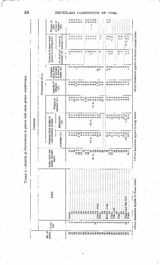
TAB
LE 5
. D
etai
ls o
f ob
serv
atio
ns a
t pl
ants
wit
h ch
ain
gra
tes
Con
tinu
ed.
O5
No.
of
plan
t. 32
33
34
35
36
37
38
39
40
41
42
43
44
45
46
47
48
49
50
51
52
53
54
55
56
57
Fur
nace
s.
Num
be
r.
2 3 '
1 5 3 3 1 2 2 8 4 24 4 3 1 1 4 6 4
. 3 2 2 2 4 16 4
Kin
d.
Pla
in ...
....
....
....
....
....
....
....
...
.....d
o.................................
.....d
o.................................
.....d
o.................................
.....d
o.................................
.....d
o.................................
.....d
o.................................
.....d
o.................................
.....d
o.................................
.....d
o..............
. .
..............
.....d
o.................................
.....d
o.................................
.....d
o.................................
.....d
o.................................
.....d
o ...
....
....
....
....
....
....
....
..P
lain
..................................
Til
e ro
of. .
.............................
.....d
o ................................
Pla
in ...
....
...:
....
....
....
....
....
....
.....d
o ...
....
....
....
....
....
....
....
.......d
o.................................
Pla
in a
nd t
ile -r
oof ..
....
....
....
....
...
Pla
in..................................
Gra
te a
rea
per
boil
er (
squa
re
feet
).
54
45
90
74.4
68
.9
33.2
56
74
.3
39.1
81
67
. 5,
54
84
49
68
90
72
42
51.6
67
.5
54
54
36
36
36
42
31.5
Dim
ensi
on
s (f
eet)
.
Dis
tanc
e fr
om g
rate
s to
tu
be h
eati
ng s
urfa
ce.
Ave
rage
(A
).
as 6.7
8.2
6.8
6.25
6.
0 6.
5 6.
0 6.
0 «3.0
, 7.
5 '8
.5
8.0
10.0
4.
1
10.5
8.
5 17
.5
7.5
6.5
17.0
5.0
18
.0
c21,
22
18.5
Min
imum
(B
).
4.3
4.7
5.5
5.8
.4
.6
4.4
4.5
4.2
6.'0
0
2.5
, 4.
5 4.
0 5.
7 6.
0 3.
9
6.5
5.5
13.0
3.
5 2.
5 14
.0
4.1
13.5
«1
6, 1
7 14
.5
Wid
th o
f fu
rnac
e (C
).
6.0
5.0
10.0
8.
5 7.
7 4.
0 6.
2 8.
25-
4.5
9.0
67.5
, 6.
0 9.
3 6.
3 8.
0 10
.0
6.5
6.4
7.5
6.0
6.0
6.0
4.0
4.0
6.0
3.5
Len
gth
of
furn
ace
(D).
9.0
9.0
9.0
8.
75
9.0
8.
3 9.0
9.0
8.
7 9.
0 9.0
9.0
7.
75
S.5
.
9.0 6.5
. 8.
0
9.0
9.0
9.0
6.
0 9.0
9.0
7.
0 9.0
Dis
tance
fr
om f
ron
t of
fu
rnac
e to
fro
nt
of
boil
er (
E). 0 .7
0 .7
5 0 0 0 0 0 0 0 0 10
.5
2.0
0
11.0
4.0
0 0 0 0 0 0 0 1.
3
Ver
tica
l dis
tance
fro
m
gra
tes
to c
okin
g a
rch
.
At
fro
nt
of
furn
ace
(F).
1.0 .9
.9
.9
.9
.9 .9
' .8
1.
0 .9
.9 .9
. .7
'1
.3
1.0
1.2 .9 1.5
1.1
At r
ear
of
furn
ace
(G).
1.5
1.4
1.
5 1.
5 1.
5 1.
5
1.
5 1.6
1.
5 1.
5 1.
5
1.6
1.0
'1.3
1.
75 1.2
1.8
c2.
3, 3
. 7
2.7
Hei
ght
of
arch
at
rea
r of
fu
rnac
e (H
).
4.6
4.
9 5.0
4.4
3.6
4.
7
3.6
4.
2 ,
3.5
3.8
4.
9
. 5.2
3.6
a F
irst
dim
ensi
on a
ppli
es t
o H
eine
boi
ler.
6 F
irst
dim
ensi
on a
ppli
es t
o la
rge
boile
r.c F
irst
dim
ensi
on a
ppli
es t
o re
turn
tub
ular
boi
ler.
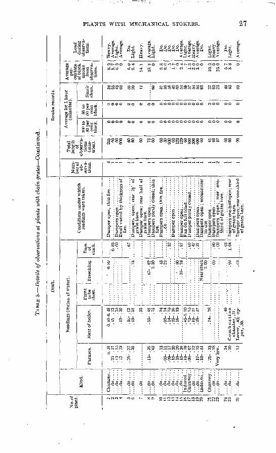
TAB
LE 5
. D
etai
ls o
f obs
erva
tion
s at
pla
nts
wit
h ch
ain
gra
tes
Conti
nued
..
No.
of
pla
nt. 1 2 3 4 5 6 7 8 9 10
11
12
13
14
15
It
i 17
18
19
20 21
22
23 24
25 o
Dra
ft.
Kin
d.
Chim
ney
. .
....
do
....
.....do.....
....do.....
....do.....
....do.....
....do.....
....do.....
....do.....
....do.....
....do.....
....do.....
....do.....
....d
o.....
Indu
ced.
.. C
him
ney.
. ....d
o.....
....d
o.....
Chi
mne
y. .
....do.....
....do.....
....do.....
....do.....
....do.....
Rea
ding
s (i
nche
s of
wat
er).
Fur
nace
.
0.26
. 2
3- .
27
. 13-
. 15
. 1
2- .
23
. 25-
. 2
7 .3
0
. 15-
. 3
6 .4
0
.13
. 03-
. 1
1 . 0
9- .
17
. 18-
. 3
0 . 1
0- .
20
. IS
- . 3
6. 1
9- .
70
. 06-
. 0
7 .1
2
. 17-
. 2
5 . I
S-
. 32
. 21-
. 2
3 .1
8
Ver
y l
ow.
.24
.20
.12
Rea
r of
boi
ler.
0. 4
0-0.
48
. 45-
. 7
3 .2
5
. 19-
. 3
0
.54
- .£
3 .4
8-
.58
. 55
. 35-
. 4
8 .7
5
.24
. 08-
. 1
4 . 1
4- .
18
. 25-
. 3
6 . 1
6- .
33
. 45-
1. 1
0 . 1
2- .
15
. 19-
. 2
1 . 2
8- .
37
. 74-
. 7
8
Fro
nt
tub
e sh
eet.
Bre
ech
ing
.
* 0.
82
....
....
..
-
.73
. 47-
. 6
21.
30 .45
.23
- '
.80
. 36-
. . 7
8
i
.40
Co
mb
usti
on
ch
amber
, .3
1.
Low
er,
.40;
up
per
, .5
0.
%
Nea
r sta
ck
2.00 .6
0
.92
.es
Bas
e of
stac
k.
0.8
5.e
o
.67
.32
.97
.60
.42
.52
.80
.eo
.63
1.04
Condit
ions
under
wh
ich
re
adin
gs
wer
e ta
ken
.
Dra
ft v
arie
d b
y t
hic
knes
s of
fi
re.
Dam
per
s open
; re
ar
IV
of
gra
te b
are.
D
amper
open
; re
ar hal
f of
g
rate
bar
e.
Dam
per
s part
ly c
lose
d; t
hin
fi
re.
Dam
per
s o
pen
; th
in f
ire.
....
Dam
per
s open
; ec
onom
izer
in
use
.
Dam
per
s open
; re
ar
one-
th
ird
of
gra
tes
bar
e.
Dam
per
s one-
hal
f open
; re
ar
of g
rate
s bar
e.
Dam
per
ope
n ; r
ear
one-
thir
d
of g
rate
s bar
e.
Sm
oke
reco
rds.
Num
ber
of
ob
serv
a
tions. 4 1 1 1 1 1 1 1 1 1 1 1 1 2 2 1 1 1 1 1 1 1 2 1 1 1
To
tal
length
of
obse
rva
ti
on
s (m
in
ute
s). 225 60
60
600 60
60 60 75
60 60
50
600 60
12
0 12
0 60
600
300
600 60 61
60
97 60
60 90
Aver
age
for
1 hour
(min
ute
s).
100
to
80 p
er
cent
bla
ck. 0 0 0 0 0 0 0 0 0 0 0 0 0 0 0 0 0 0 0 0 0 0 0 0 0 0
80 t
o
60 p
er
cent
' b
lack
. 2 0 0 0 2 0 0 0 0 0 0 0 0 0 0 0 0 0 0 0 3 0 0 0 0 0
Sta
ck
clea
n.
34
55
43
60 36
20 12 60 37
30
58
40
60
54
58
57
54
54
60 27
. 60
25 48
45 60
Av
erag
e per
ce
nta
ge
of b
lack
sm
ok
e fr
om
obse
rva
ti
on
s. 8.2
1
.7
6.3
0
&0
7.4
14.1
33.3
0
9.8
9.6
.5
1.
7 '
0
2.4
.7
1.
3 2.0
3
.0 0
10.2
0 25
.0
5.7
3
.8 0
Loa
d du
ring
ob
serv
a
tions
.
Hea
vy.
Ave
rage
. L
ight
. A
vera
ge.
Do.
Lig
ht.
Hea
vy
.
Aver
age.
L
ight.
Do.
D
o.
Do.
D
o.
Do.
A
ver
age.
L
ight.
A
ver
age.
H
eavy.
Aver
age.
D
o.
Lig
ht.
H
eavy.
Aver
age.
Do.
Lig
ht.
Aver
age.
to
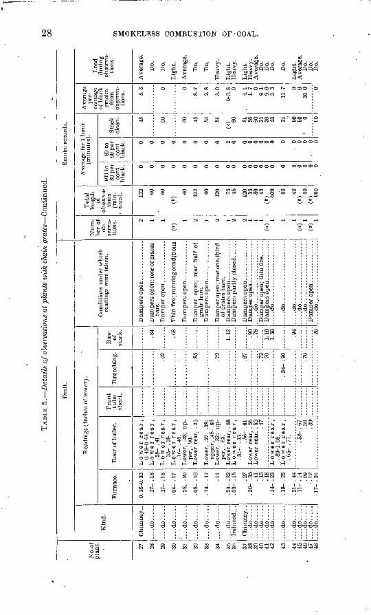
TAB
LE 5
. D
etai
ls o
f ob
serv
atio
ns a
t pl
ants
wit
h ch
ain
gra
tes
Con
tinu
ed.
to 00
No.
of
pla
nt. 27
28
29
30
31
32
33
34 35
36 37
38
39
40
41
42 43 44
45
46
47
48
Dra
ft.
Kin
d.
Ch
imn
ey..
....
do
....
.
....do.....
.....d
o.....
'....d
o.....
....do.....
....
do
....
.
....
do
....
.
....
do
....
.In
duce
d...
Ch
imn
ey..
..
..d
o..
...
....
do
....
...
..d
o..
...
....do.....
....do.....
....
do
....
.
....do.....
....
do
....
. ..
..d
o..
...
....
do
....
. ....do.....
Rea
ding
s (i
nche
s of
wat
er).
Fur
nace
.
0. 1
8-0.
32
. 17-
. 1
8
. 17-
. 1
8
. 04-
. 1
7
.28,
.2
9
. 08-
. 1
0
.14-
.17
.11
.23-
.32
.09-
.15
.27
. 36-
. 3
5 .1
1 .1
3 .1
8
. 14-
. 2
3
. 19-
. 2
5
. 31-
. 4
4.1
1-
. 14
.09
. 1
2 . 1
7- -
26
Rea
r of
boi
ler.
Lo
wer
rear,
0.
48-
0. 6
4.
Lo
wer
rear,
.3
8- .
41.
Lo
wer
rear,
33-
. 38.
L
ow
er
rear,
. 1
6- .
40.
L
ower
, .4
8; u
p
per,
. 90
. L
ower
rea
r, .
25
Low
er,
.27-
.28
; u
pp
er,
.48-
.66
Low
er,
.32;
u
p
per,
. 6
3.
Low
er r
ear,
. 5
8 L
ow
er
rear,
.3
1-
.33.
. 5
6- .
61
Low
er r
ear,
. 5
6 L
ower
rea
r, .
52
.47
Lo
wer
rear,
. 8
0-1.
08.
L
ow
er
rear,
. 6
5- .
77. .58-
.67
.3
6 .3
0
Fro
nt
tub
e sh
eet.
Bre
ech
ing
.
.52
.85
.72
.97
.72
.70
. 34
- . 9
0
.70
Bas
e of
st
ack. .84
.68
1.12 .90
.78
1.10
1.
30 .94 26
Con
diti
ons
under
whi
ch
read
ings
wer
e ta
ken
.
Dam
pers
ope
n; r
ear
of g
rate
s ba
re.
Thin
fif
e; r
unnin
g c
ondi
tion
s
Dam
per
op
en;
rear
hal
f of
g
rate
bar
e.
Dam
per
ope
n; r
ear
one-
thir
d of
gra
tes
bare
.
.....d
o...............I
......
.....d
o......................
.....d
o......................
.....d
o......................
.....d
o......................
.....d
o......................
Sm
oke
reco
rds.
Num
be
r of
ob
se
rva
ti
ons. 2 1 1
(")
1 2 1 2 1 2 2 1 1 1 (a
)
1 1 (a
)
(a)
Tot
al
leng
th
of
obse
rva
ti
ons
(min
- -
ute
s). 12
2 60
60
(6)
60
122 60
120 75
45 120 35
80
43
(6) 60
0 60 40
(")
80
(«) 60
0
Ave
rage
for
1 h
ou
r (m
inu
tes)
.
100
to
80 p
er
cent
bl
ack. 0 0 0 0 0 0 0 0 0 0 0 0 0 0 0 0 0 0 0 0 0 0
80 t
o 60
per
ce
nt
blac
k. 0 0 0 0 0 0 0 0 2 0 0 0-
0 0 0 0 0
. o 0 0
- 0 0
Sta
ck
clea
n. 45 60 60
45
53
51
<c) 60 51
56
60
21
30
53 21 60
60
» 0 CO
Ave
rage
pe
r
cent
age
of b
lack
sm
oke
from
ob
serv
a
tion
s. 5.3 0 0
.8.7
2.8
3.0
0-3.
3 0
4.1
1.7 0
9.1
9.0
3.3
11.7 0 0
30.0 0
Loa
d du
ring
ob
serv
a
tion
s.
Ave
rage
.
Do.
Do.
Lig
ht.
Ave
rage
.
Do.
Do.
Hea
vy
.
Lig
ht.
Hea
vy.
Lig
ht.
H
eav
y.
Ave
rage
. D
o.
Do.
D
o.
Do.
Lig
ht.
Ave
rage
. D
o.
Do.
D
o.
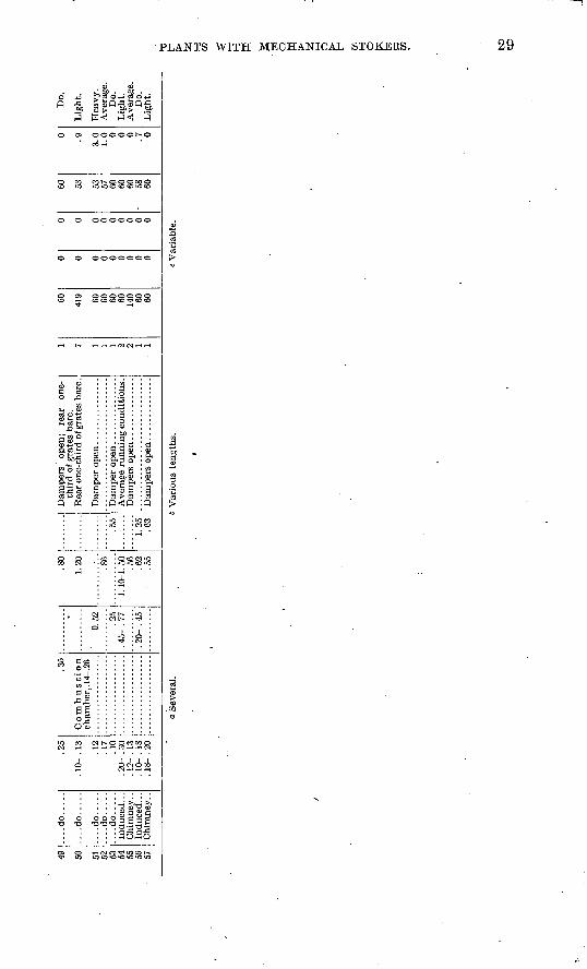
49 50 51 19 53 54 55 56 57
....do.....
....do.....
....do.....
....do.....
....do.....
.25
. 10- .
13 .12
.17
.10
. 20- .
30
. 12-
. 13
. 10-
. 18
. 18-
. 20
.35
cham
ber,
. 14
-.26
0.52 .25
. 45- .
77
.20-
.45
.80
1.20 .86
1. 10
-1. 50 .56
.62
.55
1.25 .63
thir
d of grates bare.
1 7 1 1 2 2 1 1
60 419 60 60 60 60 140 60 60
0 0 0 0 0 0 0 0 0
0 0 0 0 0 0 0 0 0
60 53 53 57 60 60 60 58 60
0 .9 3.0
1.0 0 0 0 .7 0
Do.
Lig
ht.
Hea
vy.
Ave
rage
.D
o.L
ight
.A
vera
ge.
Do.
Lig
ht.
Sev
eral
.6
Var
ious
len
gths
.V
aria
ble.
to CO
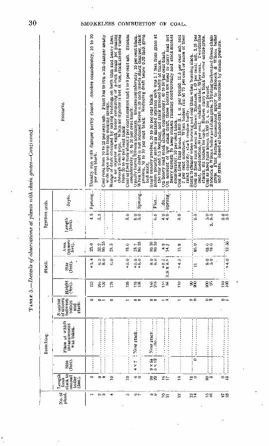
TAB
LE 5
. D
etail
s of
obse
rvat
ions
at
plan
ts w
ith
chai
n gra
tes
Con
tinu
ed.
CO
O
No.
of
plan
t. 1 2 3 4 5 6 7 8 9 10
11 12 13
14 15
16 17 18
Bre
echi
ng.
Len
gth
from
st
ack
to
near
est
boil
er
(fee
t). 5 9 4 10 10 6 0 28
22 16.
17 13 13 0 90 3 0 13
Size
(f
eet)
.
4x7
9 x 5
J 6
x 1
2 0
Pla
ce a
t w
hich
m
easu
rem
ent
was
tak
en.
.....d
o...........
Nu
mb
er
of e
lbow
s be
twee
n bo
iler
s an
d
stac
k.
0 0 1 0 1 0 0 0 0 1 3 1 2 0 0 2 0 1
Sta
ck.
Hei
ght
(fee
t).
125
216
150
175
125
175
135
185
275
116 85 110 90
2(
fo
200 95 110
100
Size
(f
eet)
.
a5.4 0.5
8.0
6.0
a 5.0
a5.5
aS
.O 8.0
8.0
o2.5
3.
8 x
3.S
a 4.
5
11 9.0
5.0
a 4.
6
Are
a (s
quar
e fe
et).
23.0
33.2
50
.25
28.3
19.6
23.7
50
.25
50.2
5 50
.25
4.9
14.7
15.9
95.0
63.6
19
.6
12.5
6
Igni
tion
arc
h.
Len
gth
(fee
t). 4.
5
3.5
3.5
5.0
3.0
6.5
4.0
4.0
3.0
3.5
5.0
3,
3.5
3.0
3.5
Sty
le.
Spru
ng..
Spr
ung.
.
Fla
t.....
...d
o..
...
Sp
run
g. .
Rem
arks
.
Usu
ally
ru
n w
ith d
amper
par
tly c
lose
d.
Sm
okes
con
side
rabl
y, 1
0 to
20
per
cen
t bl
ack.
Coa
l ru
ns
from
10
to 1
5 pe
r ce
nt
ash.
P
lant
has
to r
un w
ith d
amper
nea
rly
wid
e op
en t
o ke
ep f
rom
mak
ing s
mok
e.
Ran
ge o
f dra
ft o
btai
ned
by t
akin
g r
eadi
ngs
on b
oth
thin
and
hea
vy f
ires
. A
n ai
r in
ject
or o
n ea
ch
boil
er c
onsi
stin
g of
J-
inch
ste
am
jet
pass
ing
thro
ugh
2-in
ch p
ipe.
W
hen
air
inje
ctor
is n
ot
in u
se,
stac
k s
mok
e va
ries
fr
om 2
0 to
40
per
cen
t bl
ack.
C
oal
as f
ired
ru
ns
about 2
per
cen
t mois
ture
and
6 to
9 p
er c
ent a
sh.
Sm
okes
co
nsid
erab
ly,
10 t
o 20
per
cen
t bl
ack.
U
sual
ly b
urn
s Il
lino
is s
cree
ning
s.
Sm
okes
con
side
rabl
y, 1
0 pe
r ce
nt b
lack
. W
hen
the
dra
ft i
s no
t re
duce
d be
low
0.2
0 in
ch i
nsid
e st
ack
dam
per,
sta
ck
smok
es.
10 t
o 20
per
cen
t bl
ack.
R
educ
ing
dra
ft b
elow
0.2
0 in
ch g
ives
bad
sta
ck.
Sta
ck u
sual
ly s
mok
es,
20 t
o 30
per
cen
t b
lack
. B
efor
e pr
esen
t ar
ch w
as i
nsta
lled
ign
itio
n ar
ch w
as 1
.7 f
eet
from
gra
te a
t th
e re
ar a
nd 3
.5 f
eet^
ong,
and
sta
ck s
mok
ed b
adly
at
tim
es.
On
heav
y lo
ad s
tack
sm
okes
co
nti
nu
ou
sly,
40 t
o 50
per
cen
t bl
ack.
O
n ac
coun
t of
lo
w
stac
k d
raft
, th
ree
boil
ers
are
used
to
carr
y lo
ad n
ot
hea
vy
eno
ugh
to k
eep
stok
ers
runnin
g c
onti
nuou
sly
and
sta
ck s
mok
es
cons
ider
ably
, 10
per
cen
t bl
ack.
C
oal
as f
ired
ru
ns
about
13,0
00 B
. t.
u.
per
pound.
11.5
per
cen
t as
h, a
nd
2 pe
r ce
nt
moi
stur
e.
Whe
n bo
iler
s ru
n a
t 75
per
cen
t or
mor
e of
th
eir
rate
d c
apac
ity,
sta
ck s
mok
es b
adly
. S
tack
is
clea
ner
whe
n burn
ing n
ut
coal
th
an w
hen
burn
ing s
lack
. C
oal
as f
ired
ru
ns
about
as f
ollo
ws:
Moi
stur
e, 1
.40
per
cen
t; a
sh,
3.40
per
ce
nt;
fixe
d ca
rbon
, 60
per
cent
; vo
lati
le m
atte
r, 3
5'pe
r ce
nt.
Tw
osi
mil
ar
stac
ks;
six
boil
ers
for
each
. S
toke
rs c
arry
a t
hic
k f
ire
over
enti
re g
rate
. C
oal
as f
ired
ru
ns
about
13,3
00 B
. t.
u.
per
po
un
d.
Bab
cock
& W
ilco
x bo
iler
an
d c
hain
gra
te, 2
Sti
rlin
g bo
iler
s an
d G
reen
cha
in
grat
e.
Fir
st
furn
ace
dim
ensi
ons
apply
to
B
abco
ck
&
Wil
cox
boil
er
and g
rate
. S
peed
of
indu
ced-
draf
t fa
n co
ntro
lled
by s
team
pre
ssur
e.
w
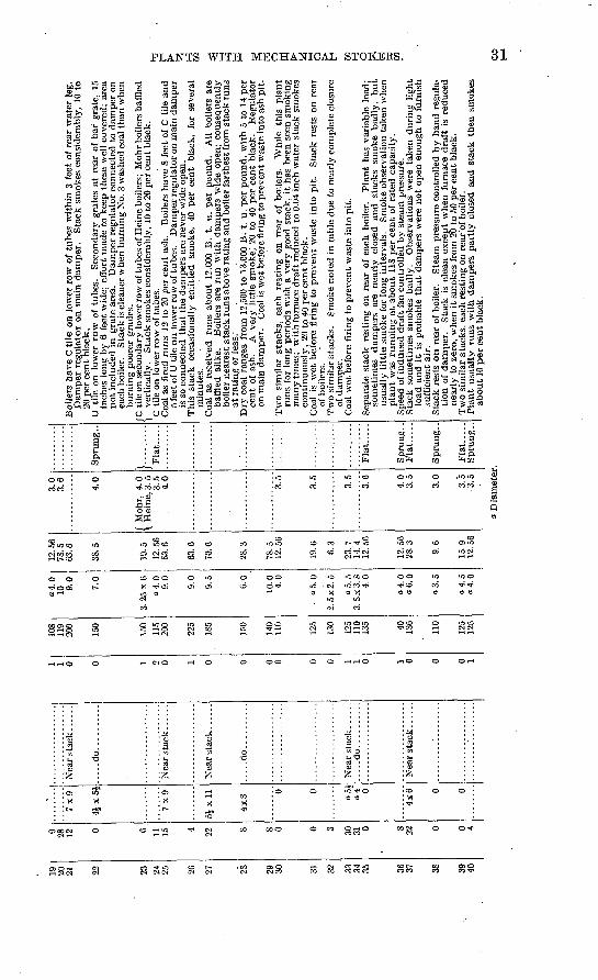
23 24 25 28 29 30 31 32 33 34 35 38
?8 1? 0 6 11 15 4 ?2 8 S 0 0 3 30
31 0 s 22 0 0 4
7x9
Ai
-v *
\1
7x9
SJxll
4x
8
0 0
o5
i o4
" 0
4x
6 0 0
....do..........
.....d
o..........
Nea
r st
ack
. ..
...
.....d
o..........
Nea
r sta
ck......
1 1 0 0 1 2 0 1 0 0 0 0 0 0 1 1 0 1 0 0 0 1
108
119
200
150
150
115
200
225
185
150
140
110
125
130
125
11.0
13
5 40
136
110
125
125
a4.0
10 9.0
7.0
3. 25 x 6
a4.0
9.0
9.0
9.5
6.0
10.0
4.0
05.0
2.5x
2.5
a 5.
5
3.8x
3.8
4.0
a 4.
0 a6.0
a 3. 5
a 4.
5
a 4.0
12.5
6 78
.5
63.6
38.5
19.5
12.5
6 63.6
63.6
70.6
28. 3
78. 5
12. 56
19.6 6.3
23.7
14.4
12.56
12.56
28.3 9.6
15.9
12.56
63.6
38.5
19.5
12.5
6 63
.6
63.6
70.6
28.3
12. 5
6
19.6
6.3
23.7
14.4
12.5
6
12.5
6 28
.3
9.6
15.9
12
.56
3.6 4.0
f M
ohr,
4.0
3.5
4.0 3.5 3.5 3.5
3.6
4.0
3.5 3.0
3.5
3.5
Spr
ung.
.
Fla
t.....
Fla
t.....
Spr
ung.
. F
lat.
....
Spr
ung.
.
Fla
t.....
Spr
ung.
.
Boi
lers
hav
e C
tile
on
low
er r
ow o
f tu
bes
wit
hin
3 fe
et o
f re
ar w
ater
leg
. D
ampe
r re
gula
tor
on m
ain
dam
per.
S
tack
sm
okes
con
side
rabl
y, 1
0 to
20
per
cen
t bl
ack.
U til
e on
low
er r
ow o
f tu
bes.
S
econ
dary
gra
tes
at r
ear
of b
ar g
rate
, 15
in
ches
lon
g by
6 f
eet
wid
e; e
ffor
t m
ade
to k
eep
thes
e w
ell
cove
red;
are
a no
t in
clud
ed i
n gr
ate
area
. D
ampe
r re
gula
tor
conn
ecte
d to
dam
per
on
each
boi
ler.
S
tack
is c
lean
er w
hen
burn
ing
No.
3 w
ashe
d co
al t
han
whe
n bu
rnin
g po
orer
gra
des.
C til
e on
sec
onda
ry lo
wer
row
of t
ubes
of H
eine
boi
lers
; M
ohr b
oile
rs b
affl
ed
vert
ical
ly.
Sta
ck s
mok
es c
onsi
dera
bly,
10
to 2
0 pe
r ce
nt b
lack
.'C
tile
on
low
er r
ow o
f tu
bes.
Coa
l as
fir
ed r
uns
12 t
o 20
per
cen
t as
h.
Boi
lers
hav
e 8
feet
of
C ti
le a
nd
5 fe
et o
f U
tile
on l
ower
row
of t
ubes
. D
ampe
r re
gula
tor o
n m
ain
dam
per
is s
o co
nnec
ted
that
the
dam
pers
are
nev
er w
ide
open
.T
his
stac
k oc
casi
onal
ly e
mit
ted
smok
e,
40 p
er c
ent
blac
k,
for
seve
ral
min
utes
.C
oal
as r
ecei
ved
runs
abo
ut 1
2,00
0 B
. t.
u.
per
poun
d.
All
boile
rs a
re
baff
led
alik
e.
Boi
lers
are
run
wit
h da
mpe
rs w
ide
open
; co
nseq
uent
ly
boile
r ne
ares
t st
ack
runs
abo
ve r
atin
g an
d bo
iler
fart
hest
fro
m s
tack
run
s at
rat
ing
or l
ess.
'D
ry c
oal
rang
es f
rom
12,
500
to 1
3,00
0 B
. t.
u.
per
poun
d, w
ith
5 to
14
per
cent
of
ash.
A
ver
y li
ttle
sm
oke,
' 20
to 4
0 pe
r ce
nt b
lack
. R
egul
ator
on
mai
n da
mpe
r.
Coa
l is
wet
bef
ore
firi
ng to
pre
vent
was
te in
to a
sh p
it.
Tw
o si
mil
ar s
tack
s, e
ach
rest
ing
on r
ear
of b
oile
rs.
Whi
le t
his
plan
t ru
ns f
or l
ong
peri
ods
wit
h a
very
goo
d st
ack,
it
has
been
see
n sm
okin
g m
any
times
; w
ith
furn
ace
draf
t re
duce
d to
0.0
4 in
ch w
ater
sta
ck s
mok
es
cont
inuo
usly
, 20
to
40 p
er c
ent
blac
k.C
oal
is w
et b
efor
e fi
ring
to
prev
ent
was
te i
nto
pit.
S
tack
res
ts o
n re
ar
of b
oile
rs.
Tw
o si
mil
ar s
tack
s.
Smok
e no
ted
in t
able
due
to
near
ly c
ompl
ete
clos
ure
of d
ampe
r.C
oal
wet
bef
ore
firi
ng t
o pr
even
t w
aste
int
o pi
t.
Sep
arat
e st
ack
rest
ing
on r
ear
of e
ach
boile
r.
Pla
nt
has
vari
able
loa
d;
som
etim
es
dam
pers
are
nea
rly
clos
ed a
nd s
tack
s sm
oke
badl
y, b
ut
usua
lly
litt
le s
mok
e fo
r lo
ng i
nter
vals
. Sm
oke
obse
rvat
ion
take
n w
hen
plan
t w
as r
unni
ng a
t ab
out
118
per
cent
of
rate
d ca
paci
ty.
Spee
d of
ind
uced
dra
ft f
an c
ontr
olle
d by
ste
am p
ress
ure.
Sta
ck s
omet
imes
sm
okes
bad
ly.
Obs
erva
tion
s w
ere
take
n du
ring
lig
ht
load
and
it
is p
roba
ble
that
dam
pers
wer
e no
t op
en e
noug
h to
fur
nish
su
ffic
ient
air
.S
tack
res
ts o
n r
ear
of b
oile
r.
Ste
am p
ress
ure
cont
roll
ed b
y ha
nd r
egul
a
tion
of
dam
per.
S
tack
is
clea
n ex
cept
whe
n fu
rnac
e dr
aft
is r
educ
ed
near
ly t
o ze
ro,
whe
n it
sm
okes
fro
m 2
0 to
50
per
cent
bla
ck.
Tw
o si
mil
ar s
tack
s, e
ach
rest
ing
on r
ear'o
f bo
iler.
Pla
nt
usua
lly
runs
wit
h da
mpe
rs p
artl
y cl
osed
and
sta
ck t
hen
smok
es
abou
t 10
per
cen
t bl
ack.
3 D
iam
eter
.C
O
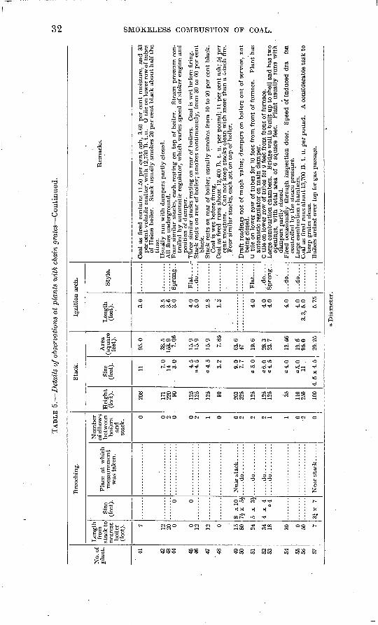
TAB
LE 5
. D
etai
ls o
f obs
erva
tion
s at
pla
nts
wit
h ch
ain
gra
tes
Con
tinu
ed.
GO to
No.
of
pla
nt. 41 42
43
44 45
46 47
'4
8 49
50 51 52
53 54 55
56 57
Bre
echi
ng.
Len
gth
from
st
ack
to
near
est
boil
er
(fee
t). 7 12
20 0 0 12 12 0 15
80 24 34
18 30 0 50 7
Size
(f
eet)
. 0 0
8 x
lO
7Jx
5
|
5 x
3£
4x
4
o4
3Jx
7
Pla
ce a
t w
hich
m
easu
rem
ent
was
tak
en.
.....d
o..........
.....d
o..........
.....d
o..........
.....d
o..........
Nu
mb
er
of e
lbow
s b
etw
een
bo
iler
s an
d st
ack.
0 0 2 0 0 2 1 0 0 2 2 2 1 1 0 2 0
Sta
ck.
Hei
ght
(fee
t).
208
171
220 90 125
125
125 90 203
325
125
125
125 35 110
250
100
Size
(f
eet)
.
11 7.0
14 3.0
4.5
o4.5
o4.5
3.2
9.0 7.7
»5.0
a6.0
a4.5
o4.0
05.0
11
.
4.5
x4.5
Are
a (s
quar
e fe
et).
95.0
38.5
15
3.9
7.06
15.9
15
.9
15.9
7.85
63.6
47 19
.6
28.3
23
.7
12.6
6
19.6
95
.0
20.2
5
Igni
tion
arc
h.
Len
gth
(fee
t). 3.0
3.5
3.6
3.0
4.0
5.0
2.8
1.3
4.0
40
4.0
4.0
40
3.3
,5.0 5.75
Sty
le.
Spr
ung.
.
Fla
t...
.'
...d
o....
Fla
t.....
...d
o....
Spr
ung.
.
...d
o....
...d
o....
Rem
arks
.
Coa
l as
fir
ed c
onta
ins
11.5
0 pe
r ce
nt
ash,
3.6
0 pe
r ce
nt
moi
stur
e, a
nd
33
per
cent
vola
tile
mat
ter,
wit
h 1
2,73
0 B
.t.u
. U
til
e on
low
er ro
w o
f tu
bes
of H
eine
boi
ler.
S
tack
usu
ally
sm
okes
20
per
cen
t b
lack
about
half
the
tim
e.
Usu
ally
run w
ith d
ampe
rs p
artl
y c
lose
d.
All
flu
es u
nder
grou
nd.
Four
sim
ilar
sta
cks,
eac
h, r
esti
ng o
n to
p of
boi
ler.
S
team
pre
ssur
e co
n
trol
led
by a
utom
atic
reg
ulat
or,
whi
ch v
arie
s sp
eed
of s
toke
r en
gine
and
po
siti
on o
f da
mpe
r.
Thr
ee s
imil
ar s
tack
s re
stin
g on
rea
r of
boi
lers
. C
oal
is w
et b
efor
e fi
ring
. S
tack
res
ts o
n re
ar o
f bo
iler
; sm
okes
con
tinu
ousl
y, f
rom
30
to 6
0 pe
r ce
nt
blac
k.
Sta
ck r
ests
on
rear
of
boil
er;
usua
lly
smok
es f
rom
10
to 2
0 pe
r ce
nt b
lack
. C
oal
is w
et b
efor
e fi
ring
. '
. C
oal
as f
ired
ru
ns
about
12,4
00 B
. t.
u.
per
pound;
11 p
er c
ent
ash;
5J
per
cent
moi
stur
e.
Can
not
keep
sta
cks
clea
n w
ith m
ore
than
a 4
-inc
h fi
re.
. Four
sim
ilar
sta
cks,
eac
h se
t on
top
of
boil
er.
Dra
ft r
eadi
ngs
not
of m
uch
valu
e; d
ampe
rs o
n bo
iler
s ou
t of
ser
vice
, no
t be
ing
clos
ed.
U ti
le o
n lo
wer
row
of
tub
es f
or 1
0 fe
et f
rom
fro
nt
of f
urna
ce.
Pla
nt
has
auto
mat
ic r
egul
ator
on
mai
n d
ampe
r.
C ti
le o
n lo
wer
row
of
tube
s fo
r 9
feet
fro
m f
ront
of
furn
ace.
L
arge
com
bust
ion
cham
bers
. B
ridg
e w
all
is b
uil
t up
to
shel
l an
d ha
s tw
o op
enin
gs,
wit
h to
tal
area
of
6 sq
uare
fee
t. P
lan
t us
uall
y ru
ns
wit
h
dam
pers
par
tly c
lose
d.
Fir
ed o
ccas
iona
lly
thro
ugh
insp
ecti
on d
oor.
S
peed
of
indu
ced
dra
fa
n co
ntro
lled
by t
he
stea
m p
ress
ure.
L
arge
com
bust
ion
cham
bers
. C
oal
as f
ired
ru
ns
about
13,7
00 B
. t.
u.
per
pou
nd.
A c
onsi
dera
ble
task
to
keep
gra
tes
clea
n.
Boi
lers
arc
hed
over
top
for
gas
pas
sage
.
o W H
F
tei
Cfi 02
O o g W cj 02 H
i <
O
o D
iam
eter
.
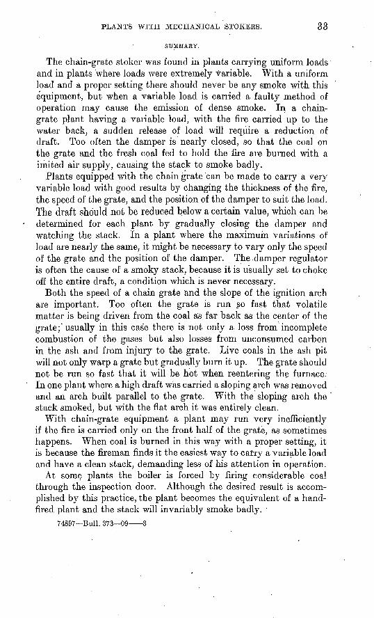
PLANTS WITH MECHANICAL STOKERS. 33
SUMMARY.
The chain-grate stoker was found in plants carrying uniform loads and in plants where loads were extremely variable. With a uniform load and a proper setting there should never be any smoke with this equipment, but when a variable load is carried a faulty method of operation may cause the emission of dense smoke. In a chain- grate plant having a variable load, with the fire carried up to the water back, a sudden release of load will require a reduction of draft. Too often the damper is nearly closed, so that the coal on the grate and the fresh coal fed to hold the fire are burned with a imited air supply, causing the stack to smoke badly.
Plants equipped with the chain grate 'can be made to carry a very variable load with good results by changing the thickness of the fire, the speed of the grate, and the position of the damper to suit the load. The draft should not be reduced below a certain value, which can be determined for each plant by gradually closing the damper and watching the stack. In a plant where the maximum variations of load are nearly the same, it might be necessary to vary only the speed of the grate and the position of the damper. The damper regulator is often the cause of a smoky stack, because it is usually set to choke off the entire draft, a condition which is never necessary.
Both the speed of a chain grate and the slope of the ignition arch are important. Too often the grate is run so fast that volatile matter is being driven from the coal as far back as the center of the grate;'usually in this case there is not only a loss from incomplete combustion of the gases but also losses from unconsumed carbon in the ash and from injury to the grate. Live coals in the ash pit will not only warp a grate but gradually burn it up. The grate should not be run so fast that it will be hot when reentering the furnace. In one plant where a high draft was carried a sloping arch was removed and an arch built parallel to the grate. With the sloping arch the stack smoked, but with the flat arch it was entirely clean.
With chain-grate equipment a plant may run very inefficiently if the fire is carried only on the front half of the grate, as sometimes happens. When coal is burned in this way with a proper setting, it is because the fireman finds it the easiest way to carry a variable load and have a clean stack, demanding less of his attention in operation.
At some plants the boiler is forced by firing considerable coal through the inspection door. Although the desired result is accom plished by this practice, the plant becomes the equivalent of a hand- fired plant and the stack will invariably smoke badly.
74897 Bull. 373 09 3
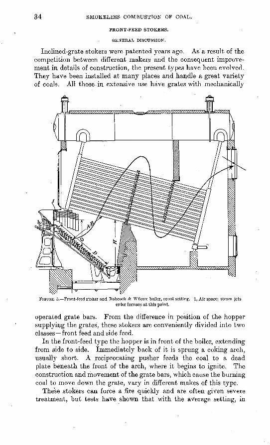
34 SMOKELESS COMBUSTION OF COAL.
FRONT-FEED STOKERS.
GENERAL DISCUSSION.
Inclined-grate stokers were patented years ago. As'a result of the competition between different makers and the consequent improve ment in details of construction, the present types have been evolved. They have been installed at many places and handle a great variety of coals. All those in extensive use have grates with mechanically
FIGURE 5. Front-feed stoker and Babcock & Wilcox boiler, usual setting. 1, Air space; steam jetsenter furnace at this point.
operated grate bars. From the difference in position of the hopper supplying the grates, these stokers are conveniently divided into two classes front feed and side feed.
In the front-feed type the hopper is in front of the boiler, extending from side to side. Immediately back of it is sprung a coking arch, usually short. A reciprocating pusher feeds the coal to a dead plate beneath the front of the arch, where it begins to ignite. The construction and movement of the grate bars, which cause the burning coal to move down the grate, vary in different makes of this type.
These stokers can force a fire quickly and are often given severe treatment, but tests have shown that with the average setting, in
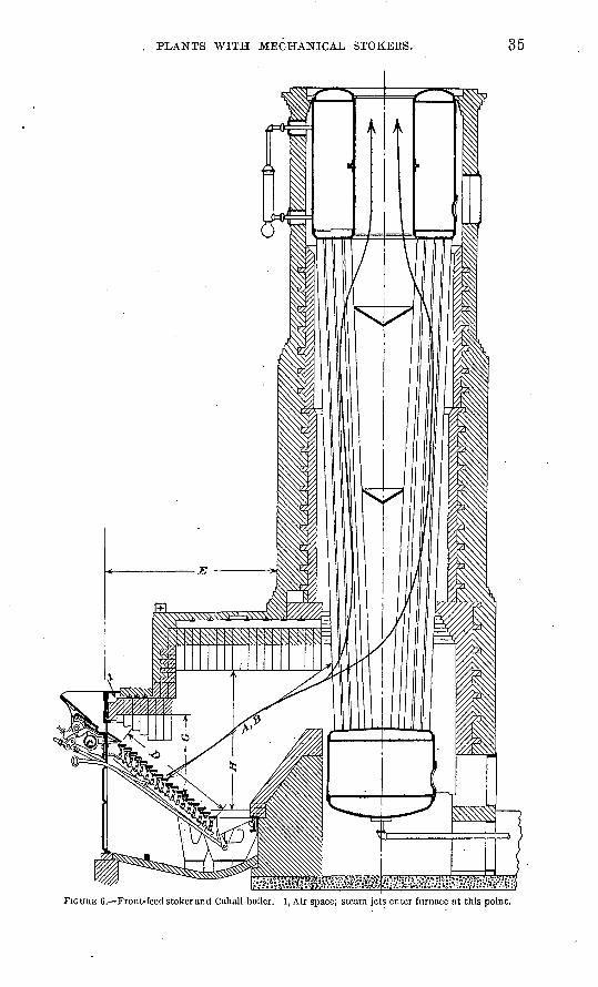
PLANTS WITH MECHANICAL STOKERS. 35
FIGURE 6. Front-feed stoker and Cahall boiler. 1, Air space; steam jets enter furnace at this point.
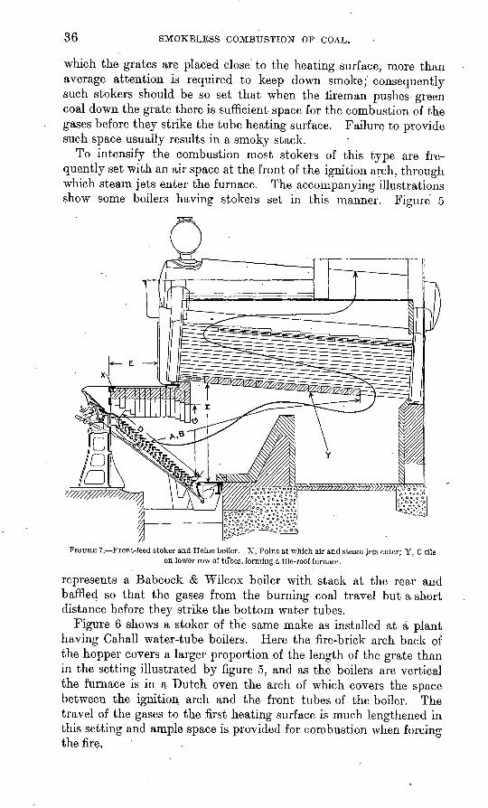
36 SMOKELESS COMBUSTION OF COAL.
which the grates are placed close 1 to the heating surface, more than average attention is required to keep down smoke;' consequently such stokers should be so set that when the fireman pushes green coal down the grate there is sufficient space for the combustion of the gases before they strike the tube heating surface. Failure to provide such space usually results in a smoky stack.
To intensify the combustion most stokers of this type are fre quently set with an air space at the front of the ignition arch, through which steam jets enter the furnace. The accompanying illustrations show some boilers having stokers set in this manner. Figure 5
FIGURE 7. Front-feed stoker and Heine boiler. X, Point at which air and steam jets enter; Y, C tile on lower row of tubes, forming a tile-roof furnace.
represents a Babcock & Wilcox boiler with stack at the rear and baffled so that the gases from the burning coal travel but a short distance before they strike the bottom water tubes.
Figure 6 shows a stoker of the same make as installed at a plant having Cahall water-tube boilers. Here the fire-brick arch back of the hopper covers a larger proportion of the length of the grate than in the setting illustrated by figure 5, and as the boilers are vertical the furnace is in a Dutch oven the arch of which covers the space between the ignition arch and the front tubes of the boiler. The travel of the gases to the first heating surface is much lengthened in this setting and ample space is provided for combustion when forcing the fire,
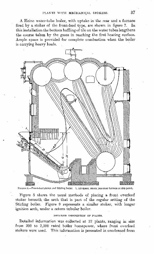
PLANTS WITH MECHANICAL STOKERS. 37
A Heine water-tube boiler, with uptake in'the rear and a furnace fired by a stoker of the front-feed type, are shown in figure 7. In this installation the bottom baffling of tile on the water tubes lengthens the course taken by the gases in reaching the first heating surface. Ample space is provided for complete combustion when the boiler is carrying heavy loads. ;
FIGURE S. Front-feed stoker and Stirling boiler. 1, Air space; steam jets enter furnace at this point.
Figure 8 shows the usual methods of placing a front overfeed stoker beneath the arch that is part of the regular setting of the Stirling boiler. Figure 9 represents a similar stoker, with longer ignition arch, under a return tubular boiler.
DETAILED DESCRIPTION OF PLANTS.
Detailed information was collected at 32 plants, ranging in size from 200 to 2,500 rated boiler horsepower, where front overfeed stokers were used. This information is presented in condensed form
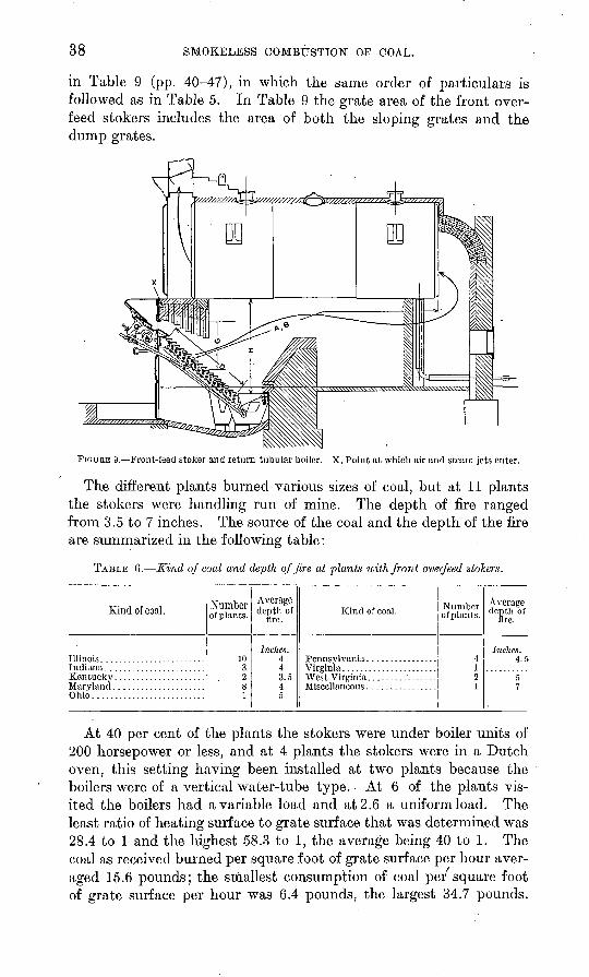
38 SMOKELESS COMBUSTION OF COAL.
in Table 9 (pp. 40-47), in which the same order of particulars is followed as in Table 5. In Table 9 the grate area of the front over feed stokers includes the area of both the sloping grates and the dump grates.
FIGURE 9. Front-feed stoker and return tubular boiler. X, Point at which air and steam jets enter.
The different plants burned various sizes of coal, but at 11 plants the stokers were handling run of mine. The depth of fire ranged from 3.5 to 7 inches. The source of the coal and the depth of the fire are summarized in the following table:
TABLE 6. Kind of coal and depth of fire at plants with front overfeed stokers.
Kind of coal.
Kentucky .....................
Ohio..........................
Numberofplants.
103281
Average depth of
lire.
Indies. 443.54
Kind of coal.
West Virginia
Number ofplants.
419
1
Average depth of
fire.
Inches.4.5
7
At 40 per cent of the plants the stokers were under boiler units of 200 horsepower or less, and at 4 plants the stokers were in a Dutch oven, this setting having been installed at two plants because the boilers were of a vertical water-tube type. At 6 of the plants vis ited the boilers had a variable load and at 2.6 a uniform load. The least ratio of heating surface to grate surface that was determined was 28.4 to 1 and the highest 58.3 to 1, the average being 40 to 1. The coal as received burned per square foot of grate surface per hour aver aged 15.6 pounds; the smallest consumption of coal per'square foot of grate surface per hour was 6.4 pounds, the largest 34.7 pounds.
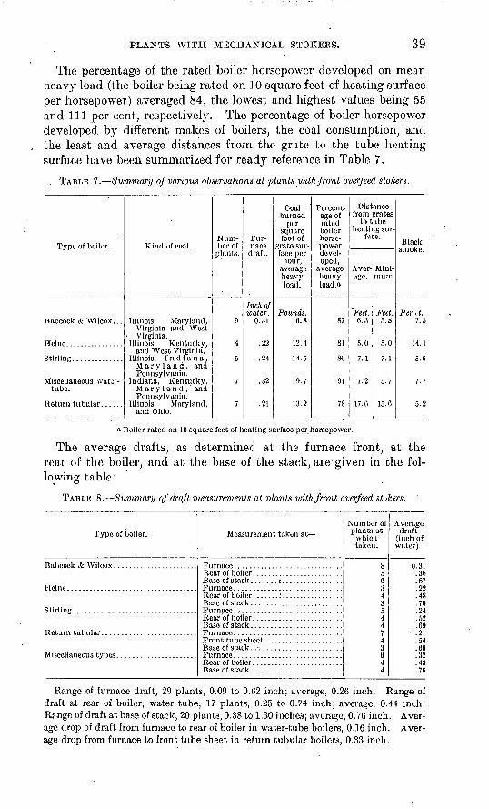
PLANTS WITH MECHANICAL STOKERS. 39
The percentage of the rated boiler horsepower developed on mean, heavy load (the boiler being rated on 10 square feet of heating surface per horsepower) averaged 84, the lowest and highest values being 55 and 111 per cent, respectively. The percentage of boiler horsepower developed by different makes of boilers, the coal consumption, and the least and average distances from the grate to the tube heating surface have been summarized for ready reference in Table 7.
. TABLE 7. Summary of various observations at plants with front overfeed stokers.
Type of boiler.
Babeock & Wilcox. . .
Stirling..............
Miscellaneous wati> tube.
Return tubular.
Kind of coal.
Illinois, Maryland, Virginia and West
Virginia. Illinois, Kentucky,
and West Virginia. Illinois, Indiana,
Maryland, and Pennsylvania.
Indiana, Kentucky, Maryland, and Pennsylvania.
Illinois, Maryland, and Ohio.
Num ber of
plants.
9
4
5
7
7
Fur nace draft.
Inch of water.
0.31
.22
.24
.32
.21
Coal burned
per square foot of
grate sur face per
hour, average heavy load.
Pounds. 10.8
12.4
14.5
19.7
13.2
Percent age of rated boiler horse power devel oped,
average heavy loacl.o
87
81
80
91
78
Distance from grates
to tube heating sur
face.
Aver age.
Feet. 6.3
5.0
7.1
7.2
17.6
Mini mum.
Feet. 5.8
5.0
7.1
5.7
15.6
Black smoke.
Pcr,t. 7.5
14.1
5.6
7.7
5.2
« Boiler rated on 10 square feet of heating surface per horsepower.
The average drafts, as determined at the furnace front, at the rear of the boiler, and at the base of the stack, are given in the fol lowing table:
TABLE 8. Summary of draft measurements at plants with front overfeed stokers.
Type of boiler.
Stirling..................................
Measurement taken at
Base of stack .........................
Number of plants at
which taken.
856343
4
7
3644
Average draft
(inch of water).
O qiVi
.87
.22
.48
.76
.24V)
09 .21
.54
.66OO
.43
.76
Range of furnace draft, 29 plants, 0.09 to 0.62 inch; average, 0.26 inch. Range of draft at rear of boiler, water tube, 17 plants, 0.25 to 0.74 inch; average, 0.44 inch. Range of draft at base of stack, 20 plants, 0.38 to 1.30 inches; average, 0.76 inch. Aver age drop of draft from furnace to rear of boiler in water-tube boilers, 0.16 inch. Aver age drop from furnace to front tube sheet in return tubular boilers, 0.33 inch.
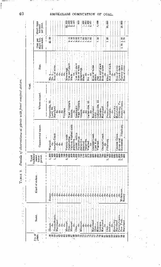
TAB
LE 9.
Det
ails
of
obse
rvat
ions
at
plan
ts w
ith
front
over
feed
sto
kers
.
No.
of
pla
nt.
.58
. 59 60
, 01 02 03 04 65 66 07
-68 69 70 71 72 73 74 75 76 77 78 79
' 80 81 82 83 84 85 86 87 88 89
Sta
te.
.....d
o.;
.:.:
.:...:
....
.....d
o...:
.....:
.:....
....
.do
....
....
...:
....
Mis
sour
i . .....
....
: . .
Ohio
.....:
.........:
..
.....d
o...:
....
....
....
Ohio
.....:
........:.
.......d
o......
....
....
..
....
.do
....
....
....
....
.....d
o......
..........
.....d
o......
....
....
.......d
o......
..........
Oh
io..
....
....
....
....
.
Indi
ana.
...
....
....
...
.....d
o........
....
...
.O
hio
....
....
....
..
.In
dia
na.
.... ........
.....d
o.... ...
....
....
.
Mar
ylan
d ..
....
....
...
Pen
nsyl
vani
a. ...
....
.N
ew Y
ork
............
Mar
ylan
d ..
....
....
...
Kin
d of
sto
ker.
.....d
o.. ...
....
....
....
....
...
...d
o..
....
....
....
....
....
....
.do
....
....
....
....
....
....
...d
o..
....
...
....
....
....
....
.do
....
....
....
....
....
.......d
o.:
....................
.....d
o......................
....
.do
....
....
....
....
....
....
...d
o..
....
....
....
....
....
....
.do
....
....
....
....
....
.......d
o:.
....................
....
.do
....
....
....
....
....
....
...d
o..
....
....
....
....
....
.....d
o......................
.....d
3. .
....
....
....
....
....
.'... .do...... ................
.....d
o......................
.....d
o......................
.....d
o......................
.....d
o......................
.....d
o......
.....
...
.....d
o......................
.....d
o......................
.....d
o......................
.....d
o.....'.................
.....d
o. .....................
....
do
....
....
....
....
....
..
....
.do
....
....
..:.
....
....
..
Tot
al
rate
d ,
hors
e-
pow
er.
1,20
030
01,
400
800
800
700
750
2,70
060
050
030
0i
snn
230
750
630
500
375
330
crm 48
050
026
0TO
O50
01,
740
450
300
200
2,80
0
800
Co
mm
erci
al n
ame.
....
.do
....
....
....
....
..
.....d
o..................
.....d
o..................
.....d
o..................
Bel
levi
lle.
. .............
Bell
ev
ille
....
....
....
...
....
.do
....
....
....
....
..
Geo
rees
Cre
ek
Coa
l.
Whe
re m
ined
.
Lad
d, 1
11
....
....
....
....
....
....
.do
....
....
....
....
....
.......d
o......................
Wes
t V
irgi
nia
....
.do
....
....
....
....
....
..
^Ves
t V
irgi
nia
i
....
.do..
. ..
....
....
....
....
.......d
o......................
....
.do
....
....
....
....
....
..
Col
linsv
ille,
11
1..
....
.. ...
...
.....d
o......................
.-...d
o......................
Size
.
No.
5...................
No.
2.... ....
....
....
..
....
.do
....
....
..'...
....
....
.do
....
....
....
....
...
...d
o..
....
....
....
...
....
.do
....
....
."..
....
..
....
.do
....
....
....
....
.
....
.do
....
....
....
....
.
....do........
....
....
.
....
.do
....
....
....
....
.
....
.do
....
....
....
....
...
...d
o..
....
....
....
...
Var
ious
siz
es
Cos
t pe
r sh
ort
ton,
de
liver
ed.
82.0
0
2.25
1.30
1.40
.2.
002.
701.
151.
00
2.12
1.90
1.50
1 30
1 Q
C
O
1 A
2 79
Sh
ort
tons
burn
ed
per
yea
r.
33, 2
002,
600
2,44
01,
445
900
1,30
01,
364
1,30
02,
567
5,00
0
30, 0
00
in R
on
CO
CO O
O g 0) d CO H
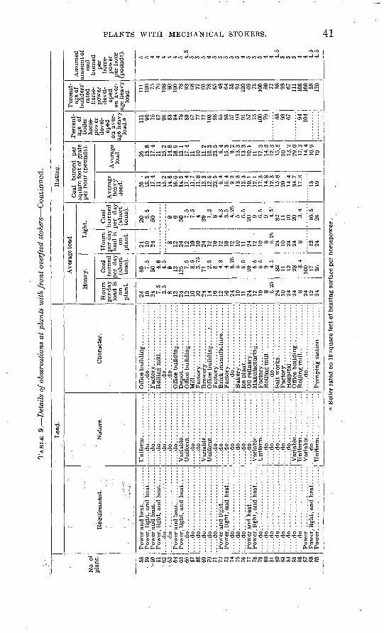
TAB
LE 9
. D
etai
ls o
f obs
erva
tion
s at
pla
nts
wit
h fr
ont
over
feed
sto
kers
Con
tinu
ed.
No.
of
plan
t. 58
59
-6
0 61
62
. :
63 64
65
66
67
68
69
70
71
72
73
74
75
76
77
78
79
80
81
82
83
84
85
86
87
88
89
Loa
d.
Req
uire
men
t.i
....
.do..
....
........:.
-......
.....d
o........
....
....
....
...
.....d
o......
....
....
....
....
.....d
o........
....
....
....
.......d
o........
....
....
....
.......d
o..........'............
.....d
o......
....
....
....
....
.....d
o......
....
....
....
....
.....d
o........
....
....
....
.......d
o........
....
....
....
.......d
o......
....
....
....
....
.....d
o.'. ....................
.....d
o........
....
....
....
....
...d
o..
....
....
....
....
....
.....d
o........
....
....
....
.......d
o......
....
....
....
....
.....d
o......
....
....
....
....
.....d
o......
....
....
....
....
.....d
o......
....
....
....
....
Nat
ure.
....
.do
....
....
....
....
...
...d
o..
....
....
....
...
....
.do
....
....
....
....
......d
o.................
.....d
o.................
.....d
o.................
.....d
o.................
.....d
o.................
Uni
form
...............
......do.................
.....d
o.................
.....d
o.................
.....d
o.................
.....d
o.................
.....d
o.................
.....d
o.................
.....d
o.................
.....d
o.................
.....d
o.................
.....d
o.................
....
.do..
....
....
....
...
Var
iabl
e ...............
.....d
o.................
Cha
ract
er.
Off
ice
bu
ild
ing
. . ...
....
....
...
...d
o..
....
....
....
....
....
Rol
ling
mil
l. ...........:.
...
....
.do
....
....
....
....
....
..O
ffic
e bu
ildi
ng. .
......... .-
.-.
Mil
l...
....
....
....
....
....
..
....
.do..
....
....
....
....
....
Rol
ling
mil
l. ................
Off
ice
buil
ding
...
....
....
...
Rat
ing.
Ave
rage
loa
d.
Hea
vy.
Hou
rs
per d
ay
load
is
on
pla
nt.
24
10
24 7.5
3.5
8 12
24
12
10
10
24
14
10
12
10
24
10
11
24
12
10 8 6.25
24
10
24
24
8 24
12
24
Coa
l bu
rned
pe
r da
y (s
hort
to
ns).
60 7.5
50 4.6
4.5
9 12
125 7.
5 8.
5 5.
75
71 2.5
8 4.3
4 8.25
5 6.
5 20
5.5
6.5
. 9 4.
5 82
11
12
28
3.4
100 17
26
Lig
ht.
Hou
rs
per
day
lo
ad i
s on
pla
nt.
24
10
24 8 12
24
12
10
10
24
12
10
12
10
12
10
11
24
12
10
8 6.25
24
10
24
24
S 12
24
Coa
l burn
ed
per
d
ay
(short
to
ns)
.
20 5.5
50 9 6 50
7.5
7.5
4 39
1.3
8 4.3
3.5
4.25
5 6.
5 20
9 6.5
9 4.5
82
11
10
20 3.4
10.5
26
Coa
l bu
rned
pe
r sq
uare
foo
t of
gra
te
per
hour
(po
unds
).
Ave
rage
he
avy
load
.
26
18
.3
17.4
11
15
.2
14.8
16
.6
14.5
17
.4
11.7
11
.8
13.3
12
.6
23.5
6.
4 16
.4
9.2
13.3
13
.3
10.1
12
.1
17.3
14
.8
12.3
15
.8
20
14.4
34
.7
17.3
13
19
Ave
rage
lo
ad.
26
15.8
17
.4
11
15.2
14
.8
16.6
13
.1
17.4
11
10
11
.2
10.3
23
.5
6.4
15.3
9.
2 13
.3
13.3
10
.1
11
17.3
14
.8
12.3
15
.8
20"
13.2
29
.0
17.3
14
.4
10.9
19
Per
cent
ag
e of
bo
iler
ho
rse
po
wer
de
vel
op
ed
on a
ver
ag
e he
avy
load
. a 111 90
75
67
96
83
94
78
89
67
77
77
10
3 98
55
93
57
93
91
57
75
100 79 88
98
67 94
10
4
Per
cent
ag
e of
bu
ilde
rs'
rate
d ho
rse
po
wer
de
vel
op
ed
on a
ver
ag
e hea
vy
load
. Ill
100 75
76
10
8 80
100 78
93
68
77
66
78
85
48
64
55
91
120 69
75
100 80
72
88
98
67
111
106
100 58
120
Ass
umed
am
ount o
f co
al
burn
ed
per
hors
e
pow
er
per
hour
(p
ound
s).
5 5 4 4 4 4 4 5 4.5
5 5 5 4 5 5 5 5 5 4 5 5 5 4 4 4.5
5 5 5 4 4 4.5
4.5
Boi
ler
rate
d on
10
squa
re f
eet
of h
eati
ng s
urfa
ce p
er h
ors
epow
er.
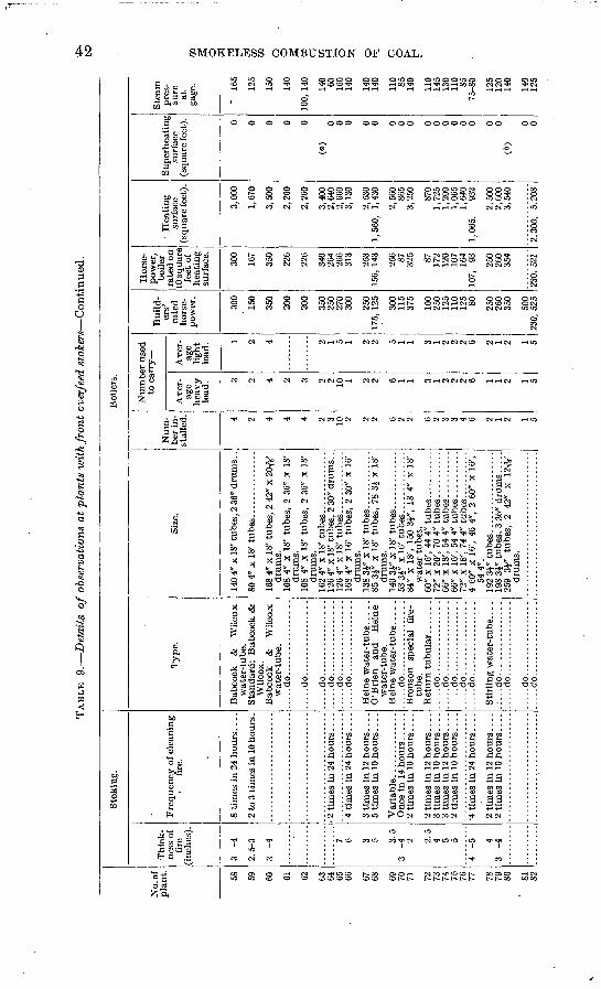
TAB
LE 9.
Det
ails
of
obse
rvat
ions
at
pla
nts
wit
h fr
ont
over
feed
sto
kers
Con
tinu
ed.
to
No.
of
plan
t. 58
59
60
61
62 63.
64
65
66 67
68 69
70
71 72
73
74
75
76
77 78
79
80 81
82
Sto
kin
g.
Thic
k
nes
s of
fi
re
(in
ches
).
3 -4
2.5
-3
3 -4 7 6 3 5 3
.5
3 -4 2 2
.5
4 5 5
4 -5 4
3 -4
Fre
quen
cy o
f cle
anin
g
fire
.
8 ti
mes
in
24 h
ours
...
.
2 to
3 ti
mes
in 1
0 ho
urs.
3 ti
mes
in
12 h
ours
. . .
. 5
tim
es i
n 10
hou
rs. .
. .
2 ti
mes
in
10 h
ours
....
2 ti
mes
in
12 h
ours
. . .
.
2 ti
mes
in
12 h
ours
...
.
Boi
lers
.
Typ
e.
Bab
cock
&
W
ilco
x w
ater
-tub
e.
Sta
ndar
d; B
abco
ck &
W
ilcox
. B
abco
ck
&
Wil
cox
wat
er-t
ube.
.....d
o.................
.....d
o.................
.....d
o.................
.....d
o.................
.....d
o.................
....
.do
....
....
....
....
.
O'B
rien
an
d H
eine
w
ater
-tub
e.
....
.do
....
....
....
....
.B
rons
on
spec
ial
fire
- tu
be.
....
.do
....
....
....
....
...
...d
o..
....
....
....
...
....
.do
....
....
....
....
...
...d
o..
....
....
....
....
...d
o..
....
....
....
...
Sti
rlin
g w
ater
-tub
e. .
. .
.:... d
o. ...............
...
...d
o..
....
....
....
...
....
.do
....
....
....
....
...
...d
o..
....
....
....
...
Size
.
140
4" x
18'
tub
es, 2
36"
dru
ms.
.
168
4" x
18'
tub
es,
2 42
" x
20TV
dr
ums.
10
8 4"
x 1
8' t
ubes
, 2
36"
x 18
' dr
ums.
10
8 4"
x 1
8' t
ubes
, 2
36"
x 18
' dr
ums.
16
2 4"
x 1
8' t
ubes
.. . .
....
....
..12
6 4"
x 1
8' t
ubes
, 2
30"
drum
s. .
1264
" x
18' t
ubes
. .............
168
4" x
16'
tub
es,
2 30
" x
16'
drum
s.
85 3
i" x
18'
tub
es,
78 3
J x
18'
drum
s.
140
3i"
Ji 1
8' t
ubes
. . ...........
53 3
i" x
16'
tubes.
.............
84"
x 18
', 15
0 3i
", 1
8 4"
x 1
8'
wat
er t
ubes
.
72"
x 20
', 70
4"
tube
s. .........
66"
x 18
', 54
4"
tube
s. . ..
....
..66
" x
!6',
54 4
" tu
bes.
...
....
..72
" x
18',
744"
tubes.
..........
4 60
" x
16',
46 4
", 2
60"
x 1
6',
544"
. 19
2 3J
" tu
bes..
....
....
....
....
198
3i"
tube
s, 3
36"
dru
ms ..
...
259
3J"
tube
s,
2 42
" x
12Ty
dr
ums.
Num
be
r in
st
alle
d. 4 2 4 4 4 2 3 10 2 2 2 6 2 2 6 2 3 3 4 6 2 1 2 1 5
Num
ber
used
to
car
ry-
Ave
r
age
heav
y lo
ad. 3 2 4 2 3 2 2 10
1 2 2 6 1 1 3 1 2 2 2 6 1 1 2 1 5
Ave
r
age
ligh
t lo
ad. 1 2 4 2 1 5 1 2 2 5 1 1 3 1 2 2 2 6 2 1 2 1 5
Bui
ld
ers'
ra
ted
hors
e
pow
er.
300
150
350
200
200
350
250
270
300
250
175,
125 300
115
375
100
250
125
110
125 SO 250
260
350
500
230,
525
Hor
se
pow
er,
boil
er
rate
d on
10
squ
are
feet
of
heat
ing
surf
ace.
300
167
350
226
226
340
264
266
313
253
156,
143 256 87
325 87
172
120
107
164
107,
93 250
260
354
230,
52i
Hea
ting
su
rfac
e (s
quar
e fe
et).
3,00
0
1,67
0
3,50
0
2,26
0
2,26
0
3,40
0 2,
640
. 2,
660
3,13
0
2,53
0 1,
560,
1,
430
2,56
0 86
5 3,
250
870
1,72
5 1,
200
1,06
5 1,
640
1, 0
65,
932
2,50
0 2,
600
3,54
0
2.30
0.
5,20
8
Sup
erhe
atin
g su
rfac
e (s
quar
e fe
et). 0 0 0 0 0
(a)
o 0 0 0 0 0 0 0 0 0 0 0 0 0 0 0(0)
0 0
Ste
am
pres
su
re
at
gage
.
' 16
5
125
150
140
100,
140 140 60
160
140
140
140
110 85
140
110
145
130
110 85
75-8
0
125
120
140
140
125
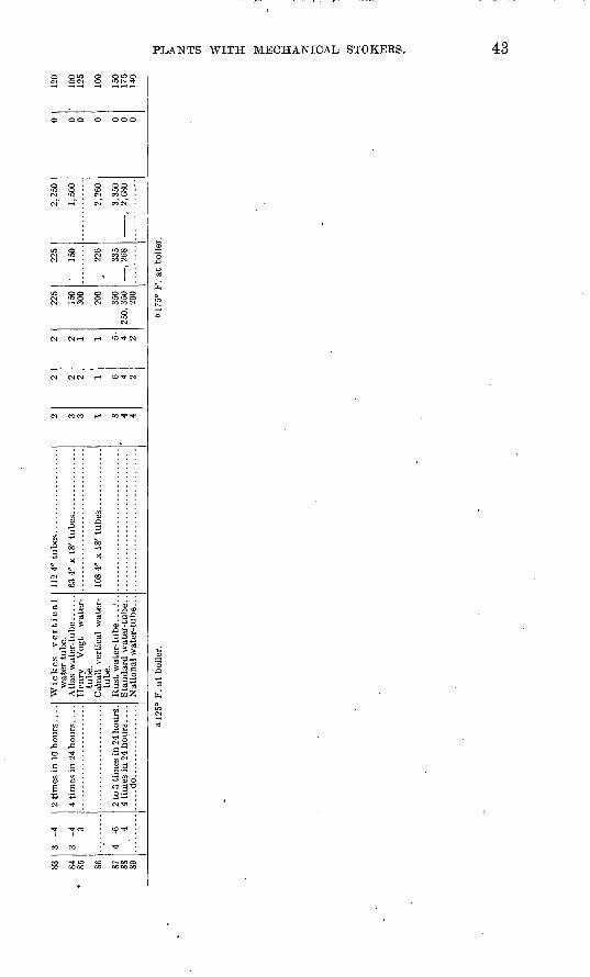
S3 84
So 86 87
88
89
3 -4
3 -4
3
4 -0
4
2 ti
mes
in
10 h
ours
...
.
4 ti
mes
in 2
4 hours
. . .
.
2 to
3 t
imes
in 2
4 hours
. 4
tim
es i
n 2
4 hours
...
. .....d
o.................
Wic
kes
vert
ical
wat
er-t
ube.
A
tlas
wat
er- t
ube ..
....
Hen
ry
Vog
t w
ater
- tu
be.
Cah
all
vert
ical
wat
er-
tube
.
Sta
nd
ard
wat
er-t
ube.
.
112
4" t
ubes.
...... ............
108
4" x
IS
' tubes
. .............
2 3 3 1 S 4 4
2 2 2 1 6 4 2
2 2 1 1 5 4 2
225
150
300
200
350
250,
350
200
225
150
220
335
<>gg
2,25
0
1,50
0
2,26
0
3,35
09
«O
rt
0 0 0 0 0 0 0
120
100
125
100
150
175
140
o!2
5°
F.
at
bo
iler
.b
175°
F.
at b
oile
r.
o Oo
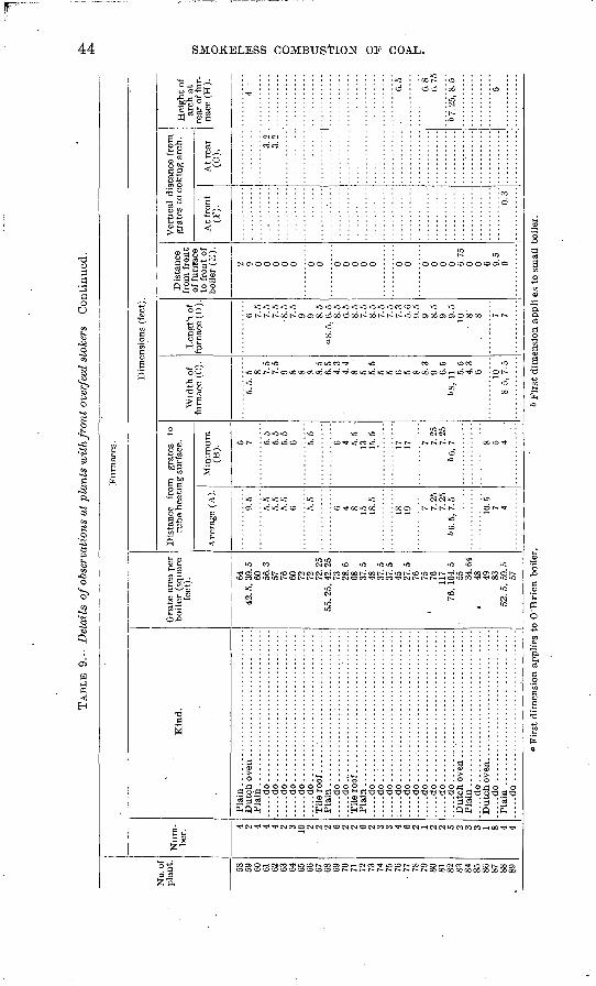
TAB
LE 9
. D
etai
ls o
f ob
serv
atio
ns a
t p
lan
ts w
ith
front
over
feed
sto
kers
Con
tinu
ed.
No.
of
plan
t. 58
59
60
61
62
63
64
65
66
67
68
69
70
71
72
73
74
75
76
77
78
79
SO
81
82
83
84
85
86
87
88
89
Fur
nace
s.
Num
be
r.
4 2 4 4 4 2 3 10 2
' 2 2 6 2 2 6 2 3 3 4 6 2 1 2 2 5 2 3 3 1 8 4 4
Kin
d.
Pla
in..................................
Pla
in ...
....
....
....
....
....
....
....
...
.....d
o..
....
....
....
....
....
....
....
...
.....d
o.................................
.....d
o.................................
.....d
o..
....
....
....
....
....
....
....
...
....
.do
........ .............
.... ..
.......d
o.................................
Til
e ro
of ...............................
Pla
in .......
. ...
...........
.....d
o..
....
....
....
.:..
....
....
.,..
.......d
o.,. ............;.
.................
Til
e ro
of ....
...........
Pla
in..
....
....
....
. ...........
.....
.....d
o..
....
....
....
....
....
....
....
...
.....d
o..
....
....
....
....
....
....
....
...
.....d
o........ ...............
. .
.....d
o..
....
....
....
....
....
....
....
...
.....d
o..
....
....
....
....
....
....
....
...
.....d
o.................;
...............
.....d
o...........................
....
.....d
o.................................
.....d
o......
. ....
.....d
o............................ ..
...
Dutc
h o
ven ............................
Pla
in ...
....
....
....
....
....
....
....
...
.....d
o.................................
Dutc
h o
ven .......................
.....
.....d
o .
...............................
Pla
in .
....
....
....
....
....
....
....
....
......d
o .
....
....
....
....
....
....
....
....
Gra
te a
rea
per
bo
iler
(sq
uare
fe
et). 64
42
. 5,
39. 5
60
56
.3
57
76
60
72
72
72.2
5 55
. 25,
42.
25
73
28.6
68
37
.5
48
37.5
37
.5
45
27.5
76
75
76
11
7 76
, 10
4. 5
55
34
.64
« 48
49
83
52
. 5,
59. 5
57
'Dim
ensi
ons
(fee
t).
Dis
tanc
e fr
om
grat
es
to
tube
hea
ting
sur
face
.
Ave
rage
(A
).
9.5
5.5
5.5
5.5
6 5.5
6 4 8 15
18.5
18
19 7 7.25
7.
25
66.5
,7.5
10.5 7 4
Min
imum
(B
).
5 7 5.5
5.5
5.5
6 5.5
6 4 5.5
13
15.5
17
17 7 7.25
7.
25
66,
7 8 5 4
Wid
th o
f fu
rnac
e (C
).
5. 5
. 5 8 7.
5 7.
5 9 8 8 8 8.
5 6.
5 4.
3 4.
4 8 5 5.
5 5 5 6 5 8 8.
3 9 6.
5 68
, 11
5.5
4.3
6 108.
5,
7. 5
Len
gth
of
furn
ace
(D).
6 7.5
7.5
7.5
8.5
7.5
9 9 8.5
"8.5
,6.5
8.
5 6.
5 8.
5 7.
5 8.
5 7.
5 7.
5 7.
3 5.
6 9.
5 9 8.
5 9 9.
5 10
8' 8 7 '7
Dis
tanc
e fr
om f
ront
of
fur
rfac
e to
fro
nt o
f bo
iler
(E
).
2 9 0 0 0 0 0 0 0 0 0 0 0 0 0 0 0 0 0 0 6.75
0 0 6 9.
5 0
Ver
tica
l di
stan
ce f
rom
gr
ates
to
coki
ng a
rch.
At
fron
t(F
).
0.3
At
rear
(G
).
3.2
3.2
Hei
ght
of
arch
at
rear
of
fur
na
ce (
H).
4 6.5
6.8
6.75
6 7.
25,
8. 5 5
O O & w
d co
"Fir
st d
imen
sion
app
lies
to
O'B
rien
boi
ler.
6 F
irst
dim
ensi
on a
pp
li e
s to
sm
all
boil
er.
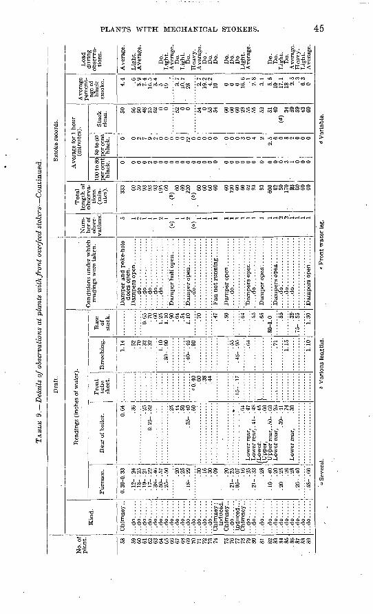
TAB
LE 9.
Det
ails
of o
bser
vati
ons
at p
lant
s w
ith
front
over
feed
sto
kers
Con
tinu
ed.
No.
of
pla
nt. 58 59
60
61
62
63
64
65
66
67
68
69
70
71
72
73
74 75
76
77
78
79
80 81 82
83
84
85
.8
6 87
SS
89
Dra
ft.
Kin
d.
Chim
ney
..
...d
o..
....
...d
o..
....
...d
o..
....
...d
o..
....
...d
o..
....
...d
o..
....
...d
o......
...d
o......
...d
o......
...d
o......
...d
o......
...d
o......
...d
o..
....
...d
o......
...d
o......
Chi
mne
y ;
indu
ced.
C
him
ney
..
Chim
ney
..
...d
o..
....
...d
o..
....
...d
o......
...d
o..
....
...d
o......
...d
o......
...d
o..
....
...d
o......
...d
o......
...d
o......
...d
o......
Rea
ding
s (i
nche
s of
wat
er).
Fur
nace
.
0. 3
0-0.
33
. 12-
. 2
4
.19-
.21
. 1
7- .
22
. 50-
. 5
7
.20
.25
-IS
- .2
2
.30
.16
.30
.09
.20
. 05-
. 0
7.1
6 .2
5 . 2
1- .
33
.28
.10-
.40
.2
0 .2
0- .
25
.26
.28
. 26-
. 4
0
Rea
r of
boi
ler. 0.
64
.36
.25
0. 2
5- .
32
.25
.44
.50
.35-
.40
.6
0
.64
Low
er r
ear,
. 4
7 L
ower
rea
r, .
41-
. 4S
/Low
er,
.45
\Up
per
, .C
O U
pper
rea
r, .
50-
.f.O
L
ower
rea
r,
. 2d
.39-
.41
.7
4 L
ower
rea
r,
. 30
Fro
nt
tube
shee
t.
«0. 4
0 '
.60
.38
.44
. 15-
. 1
7
}..
....
...
..........
Bre
echi
ng.
1.14 .52
.70
.32
.32
1.10
. S
O-
. 90
.40-
.45
.9
0
. 55
.45-
.95 .64
.71
1.15
1.10
Bas
e of
st
ack.
0.65
.7
0 .6
01.
25
1.10
.9
0 .6
4.5
41.
10 .70
.47
.SO
.64
.65
.80-
1.0 .38
.75-
.85
1.30
Con
diti
ons
under
whi
ch
read
ings
wer
e ta
ken
.
Dam
per
and
poke
-hol
e do
ors
open
.
....
.do
....
....
....
....
...
...d
o..
....
....
....
...
....
.do
....
....
....
....
...
...d
o..
....
....
....
...
.....d
o:.
...............
....
.do
... ..............
.....d
o.................
Sm
oke
reco
rds.
Num
be
r of
ob
ser
va
tion
s: 5 1 2 1 1 1 2 1 (°
)
1 2 ("
)
1 1 1 1 1 1 1 1 1 1 1 1 2 2-
1 1 1 1
Tota
l le
ngth
of
obse
rva
ti
ons
(min
ut
es). 33
3 00
59
93
93
93
195 60
(»)
60
60
120
(")
60
60
60
60 CO
120 60
CO
62
93 93 600 62
SO
17
0 93
60
60
60
Ave
rage
for
1 h
our
(min
utes
).
100
to 8
0 pe
r ce
nt
blac
k. 0 0 0 0 2 0 0 0 0 0 0 0 0 0 0 0 0 0 0 0 0 0 0 0 0 0 0 3 :
1 0 0 0
80 to
60
per
cent
bl
ack. 0 0 2 7 9 2 0 0 0 0 0 12
0 0 0 0 0 0 0 0 3 0 4 22.
5 6 0 8 2 0 0 0
Sta
ck
clea
n. 50 56
50
48
25
52 0 0 52 0 0 54 0 55
54 60
60
60
28
55
55 52 51
40
(")
34
59
59
43
60
Ave
rage
pe
rcen
t
age
of
blac
k sm
oke.
. 4.
4 .6
3.9
7.4
16.5
3.
4 5 19 3.
7 10
.7
' 28 2.
7 19
.2
4.2
10 0 0 0 16.6
.1
2.
83.
15.
5 10
17
.1
18 2.5 .3
6.3
0
Loa
d duri
ng
obse
rva
ti
ons.
Ave
rage
.
Lig
ht.
A
vera
ge.
Do.
Lig
ht.
A
vera
ge.
Do.
L
ight
. D
o.
Hea
vy
. A
vera
ge.
Do
. D
o.
Do.
Do.
D
o.
Do.
Lig
ht.
A
vera
ge.
Do.
D
o.L
ight.
D
o.
Ave
rage
. H
eav
y.
Lig
ht.
Ave
rage
.
a S
ever
al.
6 V
ario
us l
engt
hs.
<= F
ront
wat
er l
eg.
d V
aria
ble.
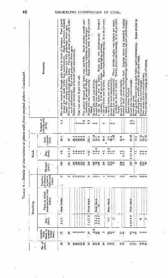
TAB
LE 9
. D
etai
ls o
f ob
serv
atio
ns a
t pl
ants
wit
h fr
on
t ov
erfe
ed s
toke
rs C
onti
nued
.05
No.
of
plan
t. 58 59 60 61 62 63 64 65 66 67 68 69 70 71 72 73 74 75 76 77 78 79 80
Len
gth
from
, st
ack
to
near
est
boile
r (f
eet)
.
10 5 0 0 5 6'
30 8.5
12 40 3 55 12 0 17 45 20 2 19 0 6 0
Siz
e (f
eet)
.
5x5
7x1
7.5
3.5
x4
5 x 3
. 5
a 5 6 o 0
Bre
echi
ng.
Plac
e at
whi
ch
mea
sure
men
t w
as
take
n.
....
.do
....
....
....
Num
ber
of e
lbow
s be
twee
n bo
iler
and
stac
k.
> 0 0 0 0 0 0 1 0 1 1 4 1 0 2 3 0 3 0 0 0
Heig
ht
(fee
t). 150
150
125
200
260 90 140
175
125 78 128 30 100
105 9G
Sta
ck.
Siz
e (f
eet)
.
«6
06
06
06
a 12 a
4. 3
o5
o5
o3.5
a 7
o3
o5
3x2 04
»5
04
Are
a (s
quar
e fe
et).
15 28.3
28.3
28.3
28.3
19 6
113.
1
12.5
614
.719
.6
19.6
9.7
38.5
7.06
19.6
6 19 6
12.5
619
612
.56
Len
gth
of
coki
ng a
rch
(fee
t). 2.4
3.
3 3 2.8
2.2
3 3 2 9 ";
2.7
Rem
arks
.
stea
m j
ets
on e
ach
boil
er r
un c
onti
nuou
sly.
S
tack
som
etim
es s
mok
ed
badl
y fo
r se
vera
l m
inut
es.
Alw
ays
run
wit
h po
ke-h
ole
door
s op
en.
used
con
tinu
ousl
y.
Run
wit
h po
ke-h
ole
door
s op
en.
tinu
ousl
y, 5
per
cen
t bl
ack.
A
utom
atic
reg
ulat
or o
n m
ain
dam
per.
blac
k.
stea
dily
, 10
to
20 p
er c
ent
blac
k.
Som
e re
fuse
bur
ned.
blac
k.
rest
ing
on f
ront
of
boile
rs'.
Stac
ks s
mok
e co
ntin
uous
ly,
10 t
o 40
per
cen
t bl
ack.
twom
ores
team
jets
ente
ring
thro
ughf
ront
of f
urna
ce, a
ll ru
n co
ntin
uous
ly.
Som
e re
fuse
bur
ned.
clea
ning
tire
, us
uall
y ab
out 2
0 pe
r ce
nt b
lack
.
Tw
o si
mil
ar s
tack
s re
stin
e on
rea
r of
boi
lers
.
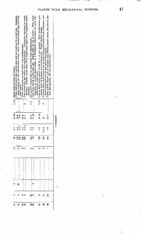
81 82 83 84 85 86 87 88 89
0 0 6 9 40 0 8 11
0 82
'
0
0 0 0 1 0 0 0 0
96f
120
\ 11
0 10
5-1
30 50 120
130
150
a 4
" 5
«5
04
04
5x5 a 6
12.5
619
.68.8
19
.623
.7
19.6
.12.
56
12.5
6
25 28.3
1.75
\ r. .
........
3 2.5 2.75
3
Sta
ck r
ests
on
rear
of b
oile
rs.
(Thr
ee b
oile
rs h
ave
lour
J-i
nch
jets
and
tw
o bo
ilers
six
J-i
nch
jets
. S
epar
ate
i. st
ack
rest
ing
on
the
rea
r of
eac
h bo
iler;
thr
ee 1
10-f
oot s
tack
s an
d tw
o 12
0-l
foot
sta
cks.
T
hree
ste
am je
ts o
n ea
ch b
oile
r ru
n co
ntin
uous
ly.
dam
per.
S
tack
s sm
oke
from
20
to 5
0 pe
r ce
nt b
lack
whe
n re
gula
tor c
lose
s da
mpe
r.
Coa
l ru
ns a
bout
12
per
cent
ash
. S
tack
res
ts o
n to
p of
boi
ler.
T
his
stac
kw
as s
een
to s
mok
e th
ree
tim
es i
n a
93-m
inut
e ob
serv
atio
n fo
r on
ly o
ne-
half
min
ute
each
tim
e.
acro
ss f
ront
of
furn
ace
run
cont
inuo
usly
. E
ight
sim
ilar
stac
ks.
hand
ope
rate
d an
d do
not
run
con
tinu
ousl
y.
firs
t ga
s pa
ssag
e, a
ll ru
n co
ntin
uous
ly.
a D
iam
eter
.
48 SMOKELESS COMBUSTION OF COAL.
SUMMARY.
A review of the remarks in the preceding table shows that with the front overfeed type of mechanical stoker, success in smoke abate ment has been attained by one of three methods the continuous use of steam jets, a generous admission of air, or careful operation.
SIDE-FEED STOKERS.
GENERAL DISCUSSION.
Like the front feed, the side-feed stoker has beeri in use for many years, the first American patent for this type having been taken out in 1878. Several firms now make such stokers, which differ chiefly in the manner of feeding coal and getting rid of clinkers and ash. In all the coal is fed from two magazines, one at each side of the boiler. At the bottom of each magazine is a flat built-up iron and steel plate called the coking plate; beneath this is an air duct and on it rests the coal-feeding mechanism. Over this feeding device is a heavy casting, the arch plate, on which rests a fire-brick arch extending over the whole grate area and having along the upper side an air duct connected with the fire space by small openings in the skew-backs supporting the arch. These openings are designed to admit hot air above the coal at a point where the volatile hydrocarbons are given off. The movable grate bars and a clinker-breaking 'device at the bottom of the V-shaped space between the grates are actuated by a small engine that forms part of the equipment.
Stokers of the side overfeed type are characterized by large coking space per foot of grate area and an ample combustion chamber. They have been installed at both large and small plants, and are successfully carrying both uniform and variable loads. In the field investigation here reported no other type of stoker was found doing as well under so great a variety of conditions. Its chief defect seems to lie in the devices for getting rid of the ash. Though supposedly automatic, they often^require the service of a fireman. This intro duces an element of varying value in the operation of the plant.
The two makes of this stoker that are most used formerly differed in arch construction, one having only side arches over the coking plates. As now installed, the arch in both makes extends over the grate area and the two styles differ merely in the devices for dis tributing coal to the grate and for getting rid of refuse. One employs for coal distribution a shaft rotating through a small arc to move stoker boxes on the coking plates; as the boxes work forward, they push coal toward the edge of the plates. Between the lower ends of the grates and supported by a bearing shaft is a hollow iron bar with projections on its surface; this bar, when rotated, grinds up the clinker. The other make feeds the coal by a screw and has heavy iron
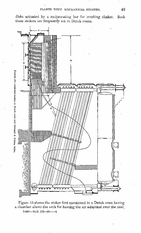
PLANTS WITH MECHANICAL STOKEES. 49
disks actuated by a reciprocating bar for crushing clinker. Both these stokers are frequently set in Dutch ovens.
AAAAA "AAAAAA "
Figure 10 shows the stoker first mentioned in a Dutch oven having a chamber above the arch for heating the air admitted over the coal,
74897 Bull. 373 09 4
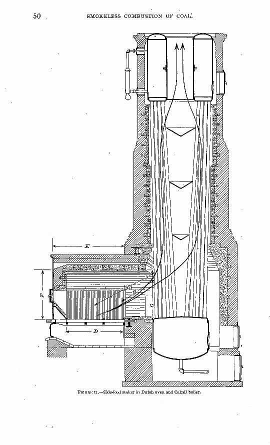
50 SMOKELESS COMBUSTION OF COAL.
FIGURE 11. Side-feed stoker in Dutch oven and Cahall boiler.
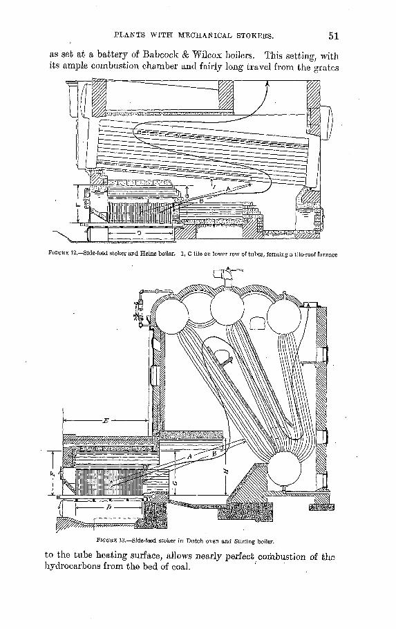
PLANTS WITH MECHANICAL STOKEBS. 51
as set at a battery of Babcock & Wilcox boilers. This setting, with its ample combustion chamber and fairly long travel from the grates
FIGURE 12. Side-feed stoker and Heine boiler. 1, C tile on lower row of tubes, forming a tile-roof furnace
FIGURE 13. Side-feed stoker in Dutch oven and Stirling boiler.
to the tube heating surface, allows nearly perfect combustion of the hydrocarbons from the bed of coal.
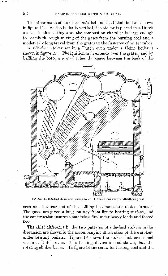
52 SMOKELESS COMBUSTION OF COAL.
The other make of stoker as installed under a Cahall boiler is shown in figure 11. As the boiler is vertical, the stoker is placed in a Dutch oven. In this setting also, the combustion chamber is large enough to permit thorough mixing of the gases from the burning coal and a moderately long travel from the grates to the first row of water tubes.
A side-feed stoker set in a Dutch oven under a Heine boiler is shown in figure 12.- The ignition arch extends over the grates, and by baffling the bottom row of tubes the space between the back of the
FIGURE 14. Side-feed stoker and Stirling boiler. 1, Continuous screw for distributing coal.
arch and the rear end of the baffling becomes a tile-roofed furnace. The gases are given a long journey from fire to heating surface, and the construction insures a smokeless fire under heavy loads and forced feed.
The chief difference in the two patterns of side-feed stokers under discussion are shown in the accompanying illustration of these stokers under Stirling boilers. Figure 13 shows the stoker first mentioned set in a Dutch oven. The feeding device is not shown, but the rotating clinker bar is. In figure 14 the screw for feeding coal and the
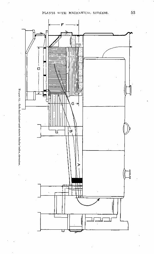
COAi
/H
I
c~-
FIGU
RE -15. S
ide-feed stoker and return tubular boiler, elevation.
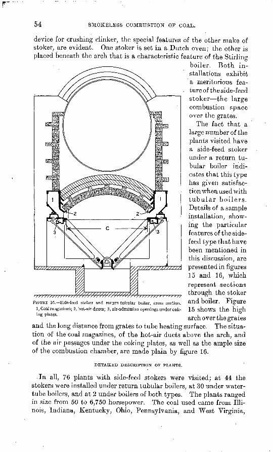
54 SMOKELESS COMBUSTION OF COAL.
device for crushing clinker, the special features of the other make of stoker, are evident. One stoker is set in a. Dutch oven; the other is placed beneath the arch that is a characteristic feature of the Stirlino-
boiler. Both in stallations exhibit a meritorious fea ture of the side-feed stoker the large combustion space over the grates.
The fact that a large number of the plants visited have a side-feed stoker under a return tu bular boiler indi cates that this type has given satisfac tion when used with tubular boilers. Details of a sample installation, show ing the particular features of the side- feed type that have been mentioned in this discussion, are presented in figures 15 and 16, which represent sections through the stoker and boiler. Figure 15 shows the high arch over the grates
and the long distance from grates to tube heating surface. The situa tion of the coal magazines, of the hot-air ducts above the arch, and of the air passages under the coking plates, as well as the ample size of the combustion chamber, are made plain by figure 16.
DETAILED DESCRIPTION OF PLANTS.
In all, 76 plants with side-feed stokers were visited; at 44 the stokers were installed under return tubular boilers, at 30 under water- tube boilers, and at 2 under boilers of both types. The plants ranged in size from 50 to 6,750 horsepower. The coal used came from Illi nois, Indiana, Kentucky, Ohio, Pennsylvania, and West Virginia,
FIGURE 10. Side-feed stoker and return tubular boiler, cross section. 1, Coal magazines; 2, hot-air ducts; 3, air-admission openings under cok ing plates.
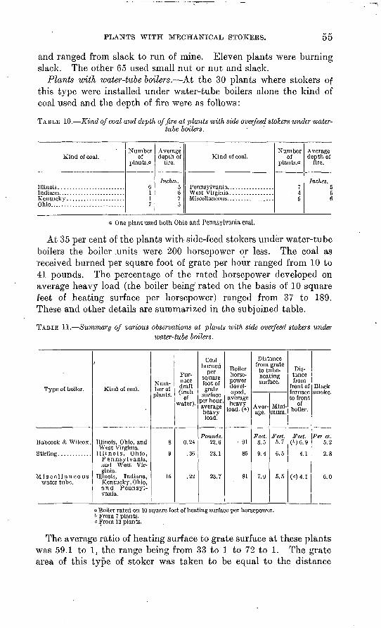
PLANTS WITH MECHANICAL STOKERS. 55
and ranged from slack to run of mine. Eleven plants were burning slack. The other 65 used small nut or nut and slack.
Plants with water-tube boilers. At the 30 plants where stokers of this type were installed under water-tube boilers alone the kind of coal used and the depth of fire were as follows:
TABLE 10. Kind of coal and depth of fire at plants with side overfeed stokers under water- tube boilers.
Kind of coal.
Ohio...........................
Number of
plants."
6117
Average depth of
lire.
Inches. 5675
Kind of coal.Number
of plants.**
7 4
5
Average depth of
fire.
Inches. 556
a One plant used both Ohio and Pennsylvania coal.
At 35 per cent of the plants with side-feed stokers under water-tube boilers the boiler .units were 200 horsepower or less. The coal as received burned per square foot of grate per hour ranged from 10 to 41 pounds. The percentage of the rated horsepower developed on average heavy load (the boiler being'rated on the basis of 10 square feet of heating surface per horsepower) ranged from 37 to 189. These and other details are summarized in the subjoined table.
TABLE 11. Summary of various observations at plants with side overfeed stokers underivater-tube boilers.
Type of boiler.
Babcock <fc Wilcox.
Stirling............
Miscellaneouswater tube.
'
Kind of coal.
Illinois, Ohio, andWest Virginia.
Illinois, Ohio,Pennsylvania,and West Virginia.
Illinois, Indiana,Kentucky, Ohio,and Pennsylvania.
Num ber of
plants.
8
9
15
Fur nace draft (inch
of water).
0.24
.36
.22
Cotilburned
sq uare foot of grate
surface per hour, average heavyload.
Pounds.22.6
23.1
23.7
Boilerhorse power devel oped,
average heavy
load, (a.)
91
85
81
Distancefrom grate
to tube-heating surface.
Aver age.
Feet.8.5
9.4
7.9
Mini mum.
Feet.5.7
6.5
5.5
Distance from
front of furnace to front
of boiler.
Feet.(6)6.9
4.1
(c)4.1
Black smoke.
Per ct.5.2
2.8
6.0
a Boiler rated on 10 square feet of heating surface per horsepower. t> From 7 plants. c From 13 plants.
The average ratio of heating surface to grate surface at these plants was 59.1 to 1, the range being from 33 to 1 to 72 to 1. The grate area of this type of stoker was taken to be equal to the distance
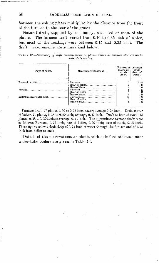
56 SMOKELESS COMBUSTION OF COAL.
between the coking plates multiplied by the distance from the front of the furnace to the rear of the grates.
Natural draft, supplied by a chimney, was used at most of the plants. The furnace draft varied from 0.10 to 0.35 inch of water, but most of the readings were between 0.15 and 0.25 inch. The draft measurements are summarized below:
TABLE 12. Summary of draft measurements at plants with side overfeed stackers underwater-tube boilers.
Type of boiler.
Stirling. ..................................
Measurement taken at Number of plants at
which taken.
772875
1278
Average draft
(inch of water).
0.24A"*
.58OR
.47Q1
.22
.51
.07
Furnace draft, 27 plants, 0.10 to 0. 53 inch water; average 0. 27 inch. Draft at rear of boiler, 21 plants, 0.18 to 0. 90 inch; average, 0. 47 inch. Draft at base of stack, 15 plants, 0.18 to 1.10 inches; average, 0. 71 inch. The approximate average drafts were as follows: Furnace, 0.25 inch; rear of boiler, 0.50 inch; base of stack, 0.75 inch. These figures show a draft drop of 0, 25 inch of water through the furnace and of 0. 25 inch from boiler to stack.
Details of the observations at plants with side-feed stokers under water-tube boilers are given in Table 13.
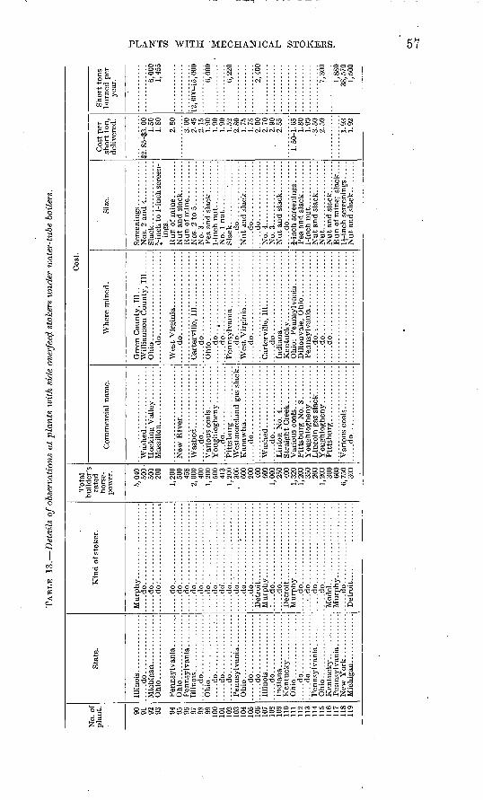
TAB
LE 13.
Det
ails
of o
bser
vati
ons
at p
lan
ts l
oith
sid
e ov
erfe
etf s
toke
rs u
nd
er w
ater
-tub
e bo
ilers
.
No.
of
pla
nt. 90 91 92 93 94 95 90 97 98 99 100
101
102
103
104
105
106
107
108
109
110
111
112
113
114
115
116
117
118
119
Sta
te.
Illi
nois
....
....
....
....
.....d
o................
Ohi
o ..
....
....
....
....
Ohi
o ..................
.....d
o................
Ohio
..................
.....d
o.............:
.......d
o................
.....d
o................
Ohio
..................
.....d
o................
.....d
o................
.....d
o................
Ohio
..................
.....d
o................
.....d
o................
Ohio
..................
Ken
tuck
y-.
. ....
....
..
Kin
d o
f st
ok
er.
.....d
o......................
....
.do
:...
....
....
....
....
..
.....d
o......................
.....d
o......................
.....d
o......................
.....d
o......................
.....d
o......................
.....d
o......................
.....d
o......................
....
.do
. .....................
.....d
o......................
.....d
o......................
.....d
o............'..........
.....d
o......................
.:...d
o......................
.....d
o......................
.....d
o......................
......do......................
.....d
o......................
.....d
o......................
Model.
......................
....
.do
. .....................
To
tal
rate
d
hors
e
pow
er.
5,04
050
050
020
0
1,20
050
045
8.
2, 0
00 400
1,20
050
041
*3
1,20
0.
306
600
200
400
GOO
1,00
025
040
0
1,20
035
020
01,
200
300
600
6,75
030
0
Co
mm
erci
al n
ame.
....
.do
....
....
....
....
..
....
.do
....
....
....
....
..
....
.do
....
....
....
....
..
....
.do
....
....
....
....
..
Coa
l.
Wh
ere
min
ed.
.....d
o......................
.....d
o......................
.....d
o......................
.....d
o......................
.....d
o..:.
......
......
......
....
.do
....
....
....
....
....
..
....
.do
....
....
....
....
....
..
....
.do
....
....
....
....
....
....
...d
o..
....
....
....
....
....
....
.do
....
....
....
....
....
..
Siz
e.
ings
.
No.
3 .................
Sla
ck..........'.......
....
.do
....
....
....
....
....
.do
....
....
....
....
....
.do
....
....
....
....
No.
4..................
No.
3..
....
....
....
....
.....d
o..........
....
..
Nut.
..................
Cos
t p
er
short
to
n,
del
iver
ed.
§2. 8
5-S3
. 00
1.50
l.SO
2.80
3.00
2.45
2.15
1.90
1.90
1.90
1.52
2.80
1.75
1.75
2.00
2.70
2.90
1.80
1.90
3.50
2.50
1.93
1.92
Sh
ort
tons
bu
rned
per
yea
r. 6,00
01,
455
12, 0
00-1
5, 0
00
6,00
0
6,22
0
2,40
0
7,30
0
1,88
038
,570
o
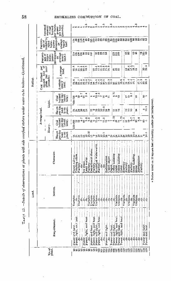
TAB
LE 1
3.
Det
ails
of o
bser
vati
ons
at p
lant
s w
ith
side
ove
rfee
d st
oker
s un
der
wat
er-t
ube
boil
ers
Co
nti
nu
ed.
Cn
oo
No.
of
plan
t. 90
91
92
93
94
95
96
97
98
99
100
101
102
103
104
105
106
107
108
109
110
111
112
113
114
115
116
117
118
119
Loa
d.
Req
uire
men
t.
.....d
o.......................
.....d
o.......................
Pow
er
.....d
o.......................
.....d
o.......................
....
.do
....
....
....
....
....
...
.....d
o.......................
.....d
o.......................
....
.do
....
....
....
....
....
...
....
.do
....
....
....
....
....
...
.....d
o.......................
....
.do
....
....
....
....
....
...
Nat
ure.
.....d
o..................
Uni
form
...
....
..*..
....
..
...d
o..
....
.:..
....
....
....
.do
....
....
....
....
....
...d
o..
....
....
....
....
....
.do
....
....
....
....
....
...d
o..
....
....
....
....
.....d
o..................
.....d
o..................
....
.do
....
....
....
....
....
...d
o..
....
....
....
....
....
.do
....
....
....
....
..
....
.do
....
....
....
....
..
....
.do
.. ...
....
....
....
.
....
.do
....
....
....
....
..
....
.do
....
....
. .........
.....d
o...................
....
.dD
.. ................
....
.do
....
....
....
....
..
Cha
ract
er.
. ....d
o...................
Mun
icip
al w
ater
wor
ks...
. ....d
o...................
....
.do
....
....
....
....
...
Off
ice
bu
ild
ing
....
....
..H
otel
...
....
....
....
....
Hot
el ...
....
....
....
....
Hot
el ...
....
....
....
....
Rat
ing.
Ave
rage
load
.
Hea
vy.
Hou
rs
per
day
load
is
on
plan
t.
24
24
24
10
24
10
10. 2
5 11
9 14 -
10
10
10
.524
5 24
11
24
12
14
24
12
10
10
10.5
24
24
11
.
8 10.5
Coa
l b
urn
ed
per
day
(s
hort
to
ns)
.
150-
200 12
19
4.7
60 2.6
6.
5 70
6 15.3
7.
3 7 15
.5
10 6 7 6.75
20
14
7.75
-
11.5
24
19
8.7
3.
5 20
8.8
7 80 5
Lig
ht.
Ho
urs
per
day
lo
ad
is o
n p
lan
t.
24
24
24
10
24
14 12
9 18
10
10
10
.5
24
19 11
24
12 12
10
10 24 8 10.5
Coa
l burn
ed
per
day
(s
hort
to
ns)
.
100-
130 8 19
4.7
25 2.4
6 4 10.4
7.
3 7 14 8 11 6.75
8 12 17
19
8.7
20 80 5
Coa
l bu
rned
pe
r sq
uare
fo
ot
of
grat
e pe
r ho
ur
(pou
nds)
.
Ave
rage
he
avy
load
.
23.8
29
31
.7
22.4
22
.3
12.4
16
.3
24.7
34
14
.6
17.4
21
.9
20.6
17
33
.3
12.2
35
26
33
18
.5
37.4
14
26
.4
17.4
16
.7
27.7
17
.2
30
20.5
Av
erag
e lo
ad.
22.8
24
31
.7
22.4
20
.5
10.2
29
13.1
17
.4
21.9
19
.5
15.3
24
.5
35
18
32 12
26.4
17
.4
16.7
14 30
20
.5
Per
cent
ag
e of
bo
iler
hors
e
pow
er
deve
lope
d on
av
erag
e he
avy
load
. a 114
106
106
104 98
44
65
145 50
68
68
73
68 12
3 11
1 10
9 62
90'
69
46 78
104 63
Per
cent
ag
e of
bu
ilde
r's
rate
d ho
rse
po
wer
de
velo
ped
on
aver
age
heav
y lo
ad. 11
4 80
106
118
104 46
69
145
133 54
59
68
73
68
120 65
123
111 80
88
96
62
95
10
0 86
46
98
71
92
63
Ass
umed
am
ount
of
coa
l bu
rned
pe
r ho
rse
po
wer
pe
r ho
ur
(pou
nds)
.
5 5 5 4 4 4.5
4 5 5 4.
5 5 5 4.
5 4 5 4.
5 5 5 5 5 5 5 5 5 4 4.
5 5 4 4 5
Boi
ler
rate
d on
10
squa
re f
eet
of h
eati
ng s
urfa
ce p
er h
orse
pow
er.
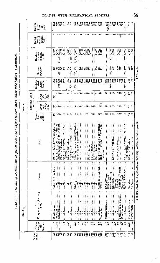
TAB
LE 13.
Det
ails
of o
bser
vati
ons
at p
lant
s w
ith
side
ove
rfee
d st
oker
s un
der
wat
er-t
ube
boil
ers
'Con
tinu
ed.
No.
of
plan
t. 90
91
92
93
94 95
96 97
98
99
100
101
102
103
104
105
106
107
108
109
110
111
112
113
114
115
116
117
118
119
Sto
kin
g.
Thi
ck
ness
of
fire
(i
nche
s). 6
3.5-
4 4 3-
6
4-6
(b) 6-
8 4-
6
5-6
5-6 4 6
4-6
4-6 4
3-4
3-6 6
6-8 5
5-6
4-6
4-5
4-6
6-10
Fre
quen
cy o
f cle
anin
g fi
re.
.....d
o..
....
....
....
.......d
o.................
.....d
o.................
.....d
o.................
.....d
o.................
.....d
o.................
.....d
o.................
.....d
o.................
....
.do
....
....
....
....
.......d
o.................
.....d
o.................
.....d
o.................
.....d
o.................
.....d
o.................
.....d
o.................
.....d
o.................
.....d
o.................
.....d
o..
....
....
....
.......d
o.................
.....d
o.................
2 ti
mes
in
12 h
ours
....
.....d
o.................
Boi
lers
.
Typ
e.
Bab
cock
& W
ilcox
. . .
. ..
...d
o..
....
....
....
...
....
.do
....
....
....
....
...
...d
o..
....
....
....
...
....
.do
....
....
....
....
.
....
.do
....
....
....
....
...
...d
o..
....
....
....
...
....
.do
....
....
....
....
...
...d
o..
....
....
....
...
....
.do
....
....
....
....
...
...d
o..
....
....
....
...
....
.do
....
....
....
....
......d
o.................
.....d
o.................
....
.do
....
....
....
....
.A
ultm
an &
Tay
lor.
. . .
Hei
ne;
Stir
ling ........
MoN
aull.
.............
Atl
as.
.................
Size
.
198
4" t
ubes
, 3 "
S"x
20i
' dru
ms
90 4
" x
18' t
ubes
, 2
30"
drum
s.
Smal
l bo
iler,
72
4" x
18'
tub
es.
1084
" x
18' t
ubes.
.............
154
4" x
18'
tub
es,
1 42
" x
20J'
drum
.
1-12
6 4"
x I
S' t
ubes
, 1-
108
4"
x 18
'. 2-
181
3J"
tube
s, 3
-403
3J"
tube
s 18
1 3J
" tu
bes,
3 3
6" d
rum
s .....
1Q9
^1" t
nh
ipQ
144
4" x
18'
tube
s, 2
36"
dru
ms.
11
3 3i
" x
16' t
ubes
, 2
30"
x 16
' dr
ums.
2-67
3i"
x 1
8' t
ubes
, 1-
138
4" x
18
' dr
ums.
19
2 4"
x 1
8' t
ubes.
.............
Num
be
r in
st
alle
d. 12 2 3 1 4 2 2 5 2 4 2 1 4 1 3 2 2 2 4 2 2 6 6 1 2 3 2 3 15 2
Num
ber
used
to
car
ry-
Ave
r
age
heav
y lo
ad.
(6) 2 1 4 1 2 4 1 3 2 1 3 1 2 2 1 1 2.5
2 1 6 4 1 2 2 1 2 12 2
Ave
r
age
light
lo
ad.
(6) 2 1 2 1 1 1 2
2 1 3 1 2 1 1 2 2 6 4 1 2
2 1 1,2 12
2
Bui
lder
s'
rate
d ho
rse
po
wer
.
420
250
200,
150
20
0 30
0
250
250,
208
250,
500
20
0'
300
250
413
300
306
200
100
200
300
250
125
200
140,
380
20
0 35
0 10
0 40
0 15
0 15
0, 3
00 450
150
Hors
e
pow
er .0
420
189
200,
150
22
7 31
8
264
264,
226
250,
500 322
214
413
300
305
200
300
184
140,
380
21
0
120
402
110,
300 40
2 15
0
Hea
ting
surf
ace
(sq
uar
e fe
et). 4,
200
1,89
0 2,
000
, 1,
500
2,
265
3,18
0
2,64
0 2,
640
, 2,
260
2, 5
00,
5, 0
00
3,22
3 2,
135
4,13
0 3,
000
3,05
0
2,00
0 3,
000
1,84
0
1, 4
02,
3, 7
95
2,09
5
1,20
0 4,
022
1, 1
00,
3, 0
00
4,02
0 1,
500
Supe
r
heat
ing
surf
ace
(squ
are
feet
).
0 0 0 0 0 0 0 6 0 0 0 0 0 0 0 0 0 0 0 0 0 0 0 0 0 58
2 0 0 0 0
Ste
am
pres
su
re
at
gage
. 160
140
130
100
145 95
85 100
150
145
100
100
150
130
110
100
115
150
100
115
105-
120
110
200
100
100
150
100
110-
115
110
110
o B
oile
r ra
ted
on 1
0 sq
uare
feet
of h
eati
ng s
urfa
ce p
er h
orse
pow
er.
b Var
iabl
e.
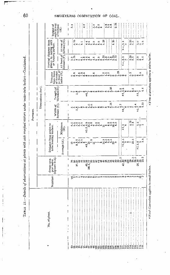
TAB
LE 13.
Det
ails
of o
bser
vati
ons
at p
lant
s w
ith
side
ove
rfee
d st
oker
s un
der
wat
er-t
ube
bo
iler
s C
onti
nued
.
* N
o. o
f p
lan
t.
90.............................................
91 92.;
...........................................
93 ..............................................
94 ... I.........................................
95.............................................
96
..................
....
....
....
....
....
....
...
97 98.............................................
99.............................................
10
0..
....
....
....
....
....
....
....
....
....
....
...
10
1.............................................
102 ..
....
....
....
....
....
....
....
....
....
....
...
10
3..
....
....
....
......
....
....
....
....
....
....
.104..................
....
....
....
....
....
....
...
10
5..
....
....
....
......
....
....
....
....
....
....
.106..................
....
....
....
....
....
....
...
10
7..
....
....
....
......
....
....
....
....
....
....
.108..
....
....
....
...............................
109 .............................................
110..
....
....
....
...............................
Ill ..
....
....
....
....
....
....
....
....
....
....
...
112 ..
....
....
....
....
....
....
....
....
....
....
...
113..
....
....
....
...............................
114.
...
....
....
....
... .....4
...... ...
....
....
..11
5 .............................................
116 .............................................
11
7..
. ...
....
....
................................
118...... ...
....
....
....
....
....
....
....
....
....
11
9..
....
....
....
....
....
....
....
....
....
....
...
Fur
nace
s.
Num
ber. 24
2 3 1 4 2 2 8 2 8 2 1 4 1 3 2 2 2 8 2 2 8 6 4 2 3 2 3 15
2
Gra
te a
rea
per
boil
er
(sq
uar
e fe
et).
70
35
36,2
5 42
56
42
42,3
6 38
.5,7
7 39
50
42
64
48
49
36
24
35
49
30
30
25.7
42
,63 36
10
0 20
59.5
26
.5
25,4
9 56
23.2
Dim
ensi
ons
(fee
t).
Dis
tanc
e fr
om g
rate
s to
tu
be
hea
ting s
urfa
ce.
Ave
rage
(A
).
10 9
8,8.
5 9.
5 8.
5 8
"8,7
14
7.5
11 7 7 8 14.5
8.
5 9.
5 5.
5 20
9
69,6
.5
9 8 10.5
67.5
,8 9 3.5
Min
imum
(B
).
6.5
5.5
5.5
6.5
5.5
6 o5.5
,4.5
10
.5
4.5
9 3.5
3.5
5 11 6 6.5
3.5
16.5
6.
5
6" 7,
3 6 4.75
7.
5
5.5
--6
---
3
Wid
th o
f fu
rnac
e (C
).
5 5 5,
6 7 8 7 6 5.6
6.5
5 7 8 8 7 6 4 6.75
- 7 3 5 4.
7 66
,7 6 5 4 7 4.4
65,7
8 5.25
Len
gth
of
furn
ace(
D).
7 7 5,
6 6 7 6 »6
,7 7 6 5 6 8 6 7 6 6 5.25
7 5 6 5.
5 67
4.5
6 5 5 8.
5 6
65,7
7 4.4
Dis
tanc
e fr
om f
ront
of f
urna
ce
to f
ront
of
boil
er (
E).
9 8.8
4 6.6
7.2
6.5
6 9 2 6.6
0 2 3 7.5
4.5
4.5
0 9 0 1.25
0 0 6 5.
3 9 0 0 8.
5 0
Ver
tica
l di
stan
ce f
rom
gr
ates
to
co
king
arc
h or
hea
ting s
urfa
ce.
At
fron
t of
fu
rnac
e (F
).
3.9
3.75
4 5 6.
1 4.
8 4.
4 4.
5 5 4.
5 5 6.
5 6 5.
25
4.8
3.5
4.8
5.25
2.
75
6~ ,
3. 3
5 3.
25
6.5
3.9
6 5.5
At
rear
of
furn
ace
(G).
3.75
4 5 6.
1
4.4
4.5
5 4.5
5 6.5
6 5.25
5.25
&"
, 3. 3
5 3.
25
6.5
3.9
6 5.5
Hei
ght
of
arch
at r
ear
of f
urna
ce
(H). 3.
9
4.8
5.5
5>
6.5
6 4.8
3.5
4.8
2.75
O W H.
O- o-
Fir
st d
imen
sion a
ppli
es t
o sm
all
bo
iler
.6
Fir
st d
imen
sion
app
lies
to
Hei
ne b
oile
r.
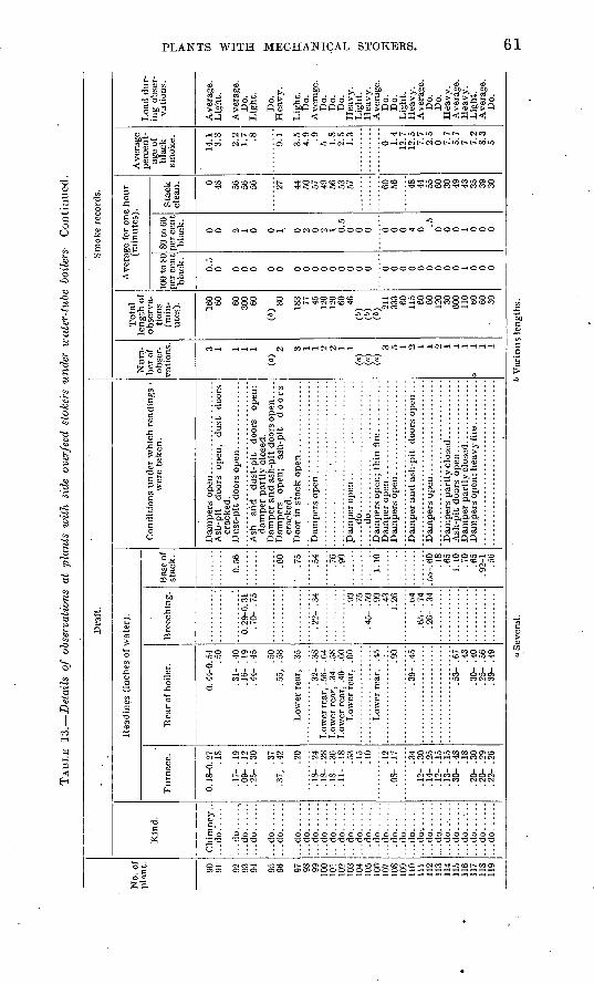
TAB
LE 13.
Det
ails
of
obse
rvat
ions
at
plan
ts w
ith
side
ove
rfee
d st
oker
s un
der
wat
er-t
ube
boil
ers
Con
tinu
ed.
No.
of
pla
nt. 90
91 92
93
94 95
96 97
98
99
10
0 10
1 10
2 10
3 10
4 10
5 10
6 10
7 10
8 10
9 11
0 11
1 11
2 11
3 11
4 11
5 11
6 11
7 11
8 11
9
Dra
ft.
Kin
d.
Chi
mne
y.-
...d
o.'..'..
'...do......
...d
o..
....
...d
o......
...d
o..
....
...d
o..
....
...d
o..
....
..
.do
....
....
.do
....
..
...d
o..
....
...d
o..
....
...d
o......
...d
o..
....
...d
o..
....
...d
o..
....
...d
o..
....
...d
o..
....
..
.do
....
..
...d
o..
....
...d
o.......
...d
o..
....
...d
o..
....
....do......
...d
o..
....
...d
o..
....
..
.do
....
.....d
o......
...d
o.. .
...
...d
o..
....
Rea
ding
s (i
nche
s of
wat
er).
Fur
nace
.
0.18
-0.2
7 .1
8
.17-
.1
9 .0
9- .
12
.25-
.30 .37
.37,
.4
2
.20
.18^
.2
4 .1
8- .
28.1
8-
.36
.11-
.1
8 .5
3 .1
5 .1
0
.12
.08-
.17 .34
.12-
.30
.14-
.25
.12-
.15
.13-
.15
.30-
.48
.1
8 .2
0- .
30
.20-
.29
.2
2- .
26
Rea
r of
boi
ler.
.50
.31-
.40
.1
6-
.19
.44-
.45 .50
.55,
.5
8
Low
er r
ear,
. 3
5
.32-
.38
Low
er r
ear,
.34
- .5
8 L
ower
rea
r, .
40-
.60
Low
er r
ear,
. 6
0
Low
er r
ear,
.4
5
.90
.39-
.45
.53-
.67
.4
3 .3
0- .
40
.25-
.56
.3
9- .
49
Bre
echi
ng.
.70-
.75
.22-
.34 .9
0 . 7
5
.90
.43
1.26 .t>
4 .6
5- .
74.2
6- .
34
Bas
e of
st
ack.
0.56 .6
0
' .7
5
.54
.76
.90
1.10
.55-
. 60
.18
.65
1.10
.7
0 .6
5 . 9
2-1
Con
diti
ons
under
whi
ch r
eadi
ngs
w
ere
taken
.
Ash
-pit
do
ors
open
, dust
do
ors
crac
ked.
Ash
ar
id
du
st-p
it
door
s op
en;
dam
per
par
tly c
lose
d.
Dam
per
and a
sh-p
it d
oors
ope
n. .
. .
Dam
pers
op
en;
ash-
pit
doors
cr
acke
d.
.....d
o...............
...........
......d
o.............................
Dam
per
an
d a
sh-p
it
door
s op
en .
. .
Sm
oke
reco
rds.
Num
be
r of
ob
ser
va
tion
s. 3 1 1 1 1
(")
2 3 1 1 2 2 1 1
(a)
(")
(«)
3
5 1 0 1 1 2 1 1 1
3
1
1
1
Tot
al
length
of
obse
rva
ti
ons
(min
ut
es). 16
0 60 60
300 60
(ft)
80 183 77
45
12
0 12
0 60
46
(ft)
(ft) (ft) 21
1 33
3 60
115 60
60
12
0 30
600
110 60
60
30
Ave
rage
for
one
ho
ur
(min
ute
s).
100
to 8
0 pe
r ce
nt
bla
ck.
0.5
0 0 0 0 0 0 0 0 0 0 0 0 0 0 0 0 0 0 0 0 0 0 0 0 1 0 0 0
80 t
o 60
pe
r ce
nt
blac
k. 0 0 2 1 0 0 1 0 2 0 2 1 0.5
0 0 0 0 0 0 4 0 .5
0 0 0 1 0 0 0
Sta
ck
clea
n. 0 48 56
56
56 27 44
50
57
49
56
53
57 60
56 48
44
55
60
30
49
43
35
39
30
Ave
rage
pe
rcen
t
age
of
blac
k sm
oke.
14.1
3.
3
2.2
1.7 .8 9.1
3.5
4.9 .9
5 1.8
2.5
1.3
0 1.4
12.7
12
.5
7.7
2.5
0 7.7
5.7
7 7.2
8.3
5
Loa
d du
r
ing
obse
r
vati
ons.
Ave
rage
. L
ight
.
Ave
rage
. D
o.
Lig
ht.
Do.
Hea
vy
.
Lig
ht.
D
o.
Ave
rage
. D
o.
Do.
D
o.
Hea
vy.
Lig
ht.
Hea
vy.
Ave
rage
. D
o."
Do.
L
ight
. H
eavy
. A
vera
ge.
Do.'
Do.
H
eavy
. A
vera
ge.
Hea
vy.
Lig
ht.
Ave
rage
. D
o.
. O
Sev
eral
.6
Var
ious
len
gths
.
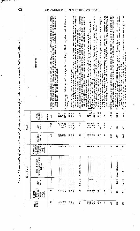
TAB
LE 1
3.
Det
ails
of
obse
rvat
ions
at
plan
ts w
ith
side
ove
rfee
d st
oker
s un
der
wat
er-t
ube
boil
ers
Con
tinu
ed.-
05
fcO
No.
of
pla
nt. 90 91 92 93 94 95 96 97 98 99 100
101
102
103
104
105
106
107
108
Len
gth
from
st
ack
to
nea
rest
bo
iler
(f
eet)
. 4 5 0 50 35 26 3 4n 12 9 0 0 15 35 3 10 11 20 11
Siz
e (f
eet)
. 0 0 0
4x4
10x4
Bre
echi
ng.
Pla
ce a
t w
hich
m
easu
rem
ent
was
ta
ken
.
-
.....d
o............
Nu
mb
er
of e
lbow
s be
twee
n bo
iler
s an
d
stac
k.
0 1 0 4 0 1 1 1 0 1 0 0 0 1 0 0 0 1 0
Hei
ght
(fee
t). 203
110
105 71 150
165
122
305
195
140
108
152
1 wi
125 80 252
127
305
Sta
ck.
Size
(f
eet)
.
a 16 a5
4x4
3x3
ol2
"5.5
o5.5
61
3x
6 05
6x6
«2.5 a3 08
«4 2x2
04
a6
Are
a . (
squa
re
feet
).
201 19
.616 9
113.
5
23.7
23.7
70.3
19.6
36 4.9 .06
33.2
K.f\
94
12.5
6
4 12.5
6
28.3
38.5
V
Rem
arks
.
pres
sure
reg
ulat
ed b
y op
enin
g an
d cl
osin
g as
h-pi
t do
ors.
P
lant
run
s in
con
nect
ion
wit
h st
orag
e bat
teri
es w
hich
are
use
d to
ass
ist
in c
arry
ing
pea
k l
oads
. S
tack
sm
oked
co
nsid
erab
ly,
10 t
o 20
per
cen
t bl
ack.
hea
vy l
oad.
hors
epow
er th
e h
eav
y
load
.- T
ry t
o ca
rry
dra
ft o
f ab
out
0.25
inc
h w
ater
in
furn
ace.
R
un w
ith d
ust
-pit
doo
rs t
hree
-qua
rter
s op
en a
nd a
sh-p
it d
oors
hal
f op
en.
too
larg
e fo
r li
ght
load
. O
n li
ght
load
ru
n w
ith
dam
per
hal
f cl
osed
, as
h-p
it a
nd d
ust-
p
it d
oors
clo
sed,
fu
rnac
e do
or
thre
e-qu
arte
rs c
lose
d.
No
dra
ft r
eadi
ngs
taken
on
acco
unt
of t
hese
con
diti
ons.
dra
ft r
educ
ed t
o 0.
07 i
nch
stac
k sm
oked
con
tinu
ousl
y, 2
0 to
40
per
cen
t bl
ack.
Murp
hy a
nd S
tirl
ing
arch
, 9
feet
. .
som
e re
adin
gs 1
0 an
d 20
per
cen
t bl
ack.
T
otal
len
gth
of M
urph
y an
d S
tirl
ing
arch
, 10
feet
.
and
100
per
cen
t bl
ack.
S
toke
r do
es n
ot
dis
trib
ute
th
e co
al e
venl
y al
ong
grat
e, a
nd f
ire
has
to
be p
oked
dow
n.
cham
ber,
als
o 16
-inc
h pr
ojec
tion
s buil
t on
bri
dge
wal
l to
def
lect
gas
es i
nwar
d.
Gas
es
cros
s th
e tu
bes
fou
r ti
mes
. V
ery
ho
t fi
re.
on l
ower
row
of t
ubes
. R
un w
ith a
sh-p
it d
oors
ope
n.
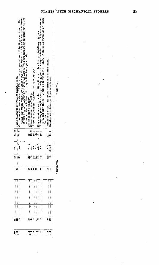
109
110
112
113
114
115
116
118
119
18 18 22 0 8 11 2 0 12
0
1 0 2 0 0 0 1 2 I
125
125
110 66 125
lye
105
120
9V
> 95
04 a 7.
104
05
o7 '
o3.5
12.5
6
40 12.5
619
.638
.5.
9.6
19 6
201 11
.1
stok
er p
er H
eine
boi
ler;
tw
o s
toke
rs p
er S
tirl
ing
boile
r.
U til
e on
low
er r
ow o
f tub
es
of H
eine
boi
ler.
A
bout
hal
f as
muc
h co
al b
urne
d pe
r fu
rnac
e un
der
Sti
rlin
g bo
ilers
as
und
er H
eine
boi
lers
. S
tirl
ing
boile
rs h
ave
poor
dra
ft.
is b
affl
ed l
ike
Hei
ne.
U ti
le o
n lo
wer
row
of
tube
s.
Aut
omat
ic r
egul
ator
on
mai
n da
mpe
r.
o D
iam
eter
.i>
Ell
ipse
.
OS
C
O
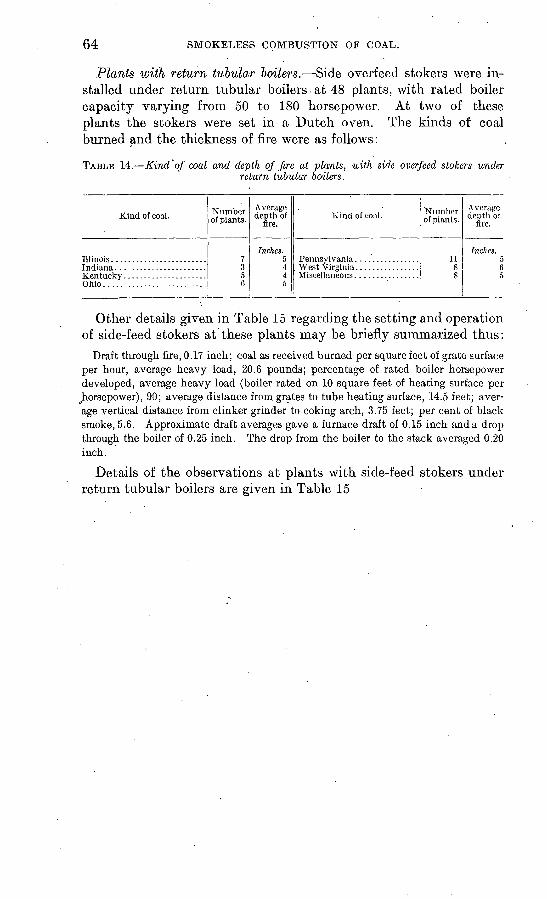
64 SMOKELESS COMBUSTION OF COAL.
Plants with return tubular boilers. Side overfeed stokers were in stalled under return tubular boilers at 48 plants, with rated boiler capacity varying from 50 to 180 horsepower. At two of these plants the stokers were set in a Dutch oven. The kinds of coal burned and the thickness of fire were as follows:
TABLE 14. Kind of coal and depth of fire at plants, with side overfeed stokers underreturn tubular boilers.
Kind of coal.
Ohio..........................
Number of plants.
7356
Average depth of
fire.
Inches. 5445
Kind of coal. 'Number of plants.
118S
Average depth of
fire.
Inches.
05
Other details given in Table 15 regarding the setting and operation of side-feed stokers at these plants may be briefly summarized thus:
Draft through fire, 0.17 inch; coal as received burned per square feet of grate surface per hour, average heavy load, 20.6 pounds; percentage of rated boiler horsepower developed, average heavy load (boiler rated on 10 square feet of heating surface per
^horsepower), 90; average distance from grates to tube heating surface, 14.5 feet; aver age vertical distance from clinker grinder to coking arch, 3.75 feet; per cent of black smoke, 5.6. Approximate draft averages gave a furnace draft of 0.15 inch and a drop through the boiler of 0.25 inch. The drop from the boiler to the stack averaged 0.20 inch.
Details of the observations at plants with side-feed stokers under return tubular boilers are given in Table 15
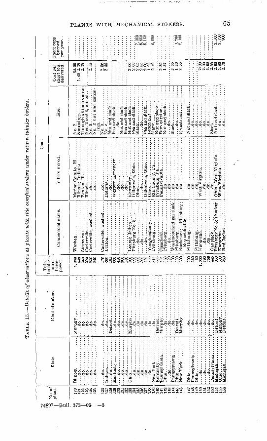
TAB
LE 15.
Det
ails
of o
bser
vati
ons
at p
lan
ts w
ith
side
ove
rfee
d st
oker
s un
der
retu
rn t
ubul
ar b
oile
rs.
No.
of
pla
nt.
120
121
199
19^
124
1O
C
19A
197
12
913
013
11 39
IQO
134
135
1 Q
ft-l
OQ
140
141
I/O 14
3
' 14
514
6
147
148
i *in
151
1 *\
91^3
154
155
156
Sta
te.
.....d
o.................
....do.................
....
do
....
....
....
....
......d
o.................
....
.do
....
....
....
....
.
.....d
o.................
.....d
o.................
.....d
o.................
.....d
o.................
.....d
o.................
.....d
o.................
.....d
o.................
.....d
o.................
.....d
o.................
.....d
o.................
Ohi
o. ...
....
....
....
.......d
o.................
.....d
o.................
.....d
o.................
.....d
o.................
Mic
hig
an
....
....
....
..
Ohio
..................
Mic
higa
n. ..
...........
Kin
d o
f sto
ker.
.....d
o."
...'....-.
.......-
.....
.....d
o.......................
....
do..
....
....
....
....
....
....
...d
o..
... ..................
....
.do..
....
....
....
....
....
.
....
.do..
....
....
....
....
....
......d
o.......................
.....d
o.......................
....
.do..
....
....
....
....
....
......d
o.......................
.....d
o.......................
.....d
o.......................
....
.do
....
.--.
-...
...-
...-
-..
....
.do
....
.-..
.---
-...
-...
...
.....d
o.......................
.....d
o...... .................
.....dO
..-...-...--.......-...
.....d
o.......................
.....d
o.......................
..:.
. do..
....
.................
.....d
o.......................
....
.do..
....
-.--
..-.
-.--
..-.
.......d
o.......................
....
.do
....
.--.
...-
...-
-.--
.-.
....
.do
....
...-
-.-.
.-..
..-.
...
Det
roit
..... .................
Det
roit
......................
Tot
al
rate
d ho
rse
po
wer
.
640
360
320
9^n
400
1Q
=
onn
100
600
600
500
450
Ofi
n
874
600
405
320
on
n
300
Of\
fl
900
150 50
1,00
079
075
044
535
0or
\n
250
Com
mer
cial
nam
e.
.....d
o...................
.....d
o...................
.....d
o...................
Rey
nold
svil
le.
....
.do
. ...
....
....
....
...
.....d
o...................
Pit
tsburg
No.
8; T
hack
er.
Red
Jac
ket
. . .....'.......
Coa
l.
Whe
re m
ined
.
.....d
o.......................
.....d
o........................
.....d
o........-.
....-.
---.
...
.....d
o.......................
.....d
o........-.
-..-
-..-
.....
. ....d
o..... ...............
...
Oh
io........................
.... .do...... .................
Pit
tsb
urg
, P
a...... ...
....
..
.....d
o.......................
.....d
o.......................
.....d
o.......................
... ..
do
. ...
....
....
....
....
. ..
.....d
o.......................
.... .
do. .
....
....
....
.. .......
.....d
o.......................
....
.do
....
....
....
....
....
...
.....d
o.......................
....
.do
....
....
....
....
....
...
Ohi
o;
Wes
t V
irg
inia
. ..
....
.
.....d
o.............. .........
Size
.
No.
2...................
No.
3.... .......
. ..
....
.
ings
. N
o. 3
. ...
....
....
....
...
No.
4...................
.....d
o...... ...... ......
Nut
and
slac
k. .........
Sla
ck..
....
.............
....
.do..
....
......
...:
..P
ea a
nd s
lack..
....
....
Sla
ck..........
....
....
.N
ut
and
slac
k. .........
Nut
and s
lack
. .........
. ....d
o. ..
....
... ..
....
. .
Sla
ck...................
....
.do..
....
....
....
....
IJ-i
nch
nut.
............
.....d
o..................
.....d
o........--
--.-
--..
....
.do..
....
....
....
....
. ...
.do
....
. ....
....
.. ...
.....d
o. .
........
........
Sla
ck...................
Nut
and
slac
k... ..
....
. .....d
o..................
.....d
o..........
....
....
Cos
t pe
r sh
ort
ton
, de
live
red.
§2.9
01.
80-2
.35
2.35
2.15
2.80
2.35
2.00
2.00
2.05
2.35
2.00
1.90
2.40
2.80
1.87
3.00
1.80
2.55
2:00
2.00
1.69
2.55
2.60
1.
902.
70
Sh
ort
tons
bu
rned
p
er y
ear.
.
7,30
05,
500
5,10
0
6,00
0
1,20
02,
100
2,56
0 2,
730
900
fed
c
OS
O
l
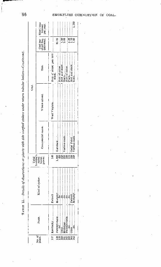
TAB
LE 1
5.
Det
ails
of o
bser
vati
ons
at p
lant
s w
ith
side
ove
rfee
d st
oker
s un
der
retu
rn t
ubul
ar b
oil
ers
Co
nti
nu
ed.
No.
of
pla
nt.
157
158
159
ICO
161
102
163
164
165
Sta
te.
Oh
io..
....
....
....
....
Ohio
..................
....
.do
....
....
.........
Kin
d o
f st
oker
.
....
.do..
....
....
....
....
....
......d
o.......................
.....d
o.......................
.....d
o.......................
Tot
al
rate
d
hors
e
pow
er.
140
1,00
045
025
020
0IS
O17
915
0
Com
mer
cial
nam
e.
Coa
l.
Whe
re m
ined
.Si
ze.
slac
k.
Sla
ck..
....
....
....
....
.
Sla
ck..
....
....
....
....
.
Cos
t per
sh
ort
ton,
de
live
red.
S3. 0
5
1.90
2.00
3.30
1.70
1.85
Sho
rt t
ons
burn
ed
per
year
.
OS
OS
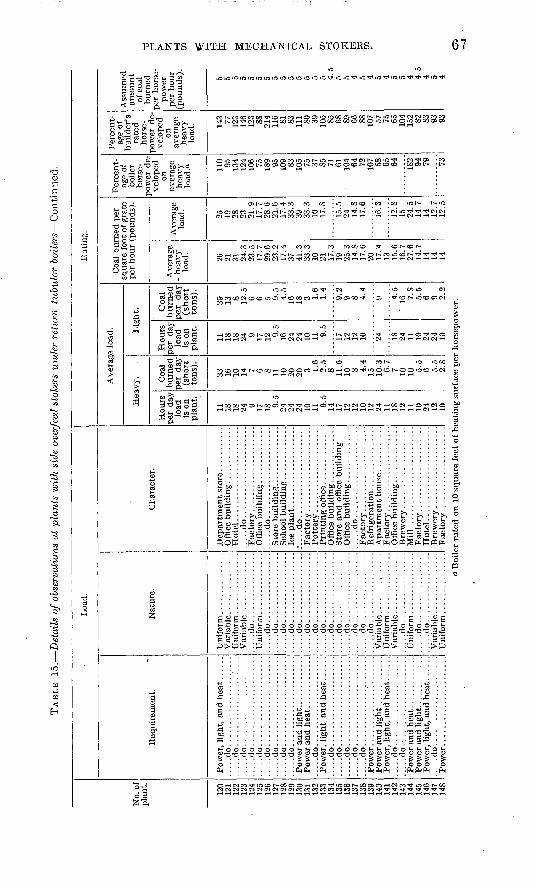
TAB
LE 15.
Det
ails
of
obse
rvat
ions
at
plan
ts w
ith
side
ove
rfee
d st
oker
s un
der
retu
rn t
ubul
ar b
oil
ers
Con
tinu
ed.
No.
of
plan
t.
120
121
122
123
124
125
126
127
128
129
130
131
132
133
134
135
136
137
138
139
140
141
142
143
144
145
146
147
148
Loa
d.
Req
uire
men
t.
.....d
o........
....
....
..'...
...
...d
o..
....
....
....
....
....
.....d
o......................
....
.do
....
....
....
....
....
....
...d
o..
....
....
....
....
....
....
.do
....
....
....
....
....
....
...d
o..
....
....
....
....
....
....
.do
....
....
....
....
....
..
.....d
o......................
....
.do
....
....
....
....
....
....
...d
o..
....
....
....
....
....
.....d
o......................
.....d
o......................
....
.do
....
....
....
....
....
....
...d
o..
....
....
....
....
....
.
.....d
o........
....
....
....
..P
ow
er.
....
....
....
....
....
.
Nat
ure.
.....d
o.................
.....d
o. ................
.....d
o.................
.....d
o.................
.....d
o.................
.....d
o.................
.....d
o.................
.....d
o.................
.....d
o.................
.....d
o.................
.....d
o.................
.....d
o.................
.....d
o.................
.....d
o.................
.....d
o.................
.....d
o.................
.....d
o.................
Uni
form
...............
Cha
ract
er.
.....d
o......................
....
.do
....
....
....
....
....
..
Stor
e an
d of
fice
buil
ding
. . .
.
.....d
o......................
Mil
l...
....
....
....
....
....
..
Fac
torv
.....................
Eat
ing.
Ave
rage
loa
d.
Hea
vy.
Hou
rs
per
day
load
is
on
plan
t.
11
IS
18
24 9 17
IS 9.5
24
24
24
10
11
9.5
14
17
12
12
10
12
24
11
18
12
11
10
24
12
10
Coa
l bu
rned
pe
r da
y (s
hort
to
ns).
33
16
10
14 7 6 8 11
10
20
20 3 1.6
2.5
8 11.6
10
S 4.4
15
10.3
6.7
7 10
10 5.5
6 5.5
2.S
Lig
ht.
Ho
urs
per
day
lo
ad
is o
n pla
nt.
11
18
IS
24 9 17
12 9.5
16
24
24
10
11 9.5
17
12
12
10 24 IS
24
11
10
24
24
10
Co
al
bu
rned
p
er
day
(s
ho
rt
tons)
.
39
13 S 12.5
6 6 5 9
.5
4.5
16
IS 3 1.6
1.4
9.2
9 8 4.4
9 4.5
' 16
7.S
5.5
6 9 2
.2
Coa
l burn
ed p
er
squar
e fo
ot o
f g
rate
per
hour
(pounds)
.
Aver
age
- hea
vy
load
.
26
21
31
24.3
23
.5
17.7
29
.6
23.2
17
.4
37
41.3
33
.3
10
21
17.3
19
25.3
14
.8
17.6
20
17
.4
13
15.6
16
.7
27.6
14
.7
14
14
14
Ave
rage
lo
ad.
25
19
28
23
21.9
17
.7
28.6
21
.6
17.4
33
.3
39
33.3
10
17
.8
15.5
24
14
. S
17.6
16.3
12.8
15
24
.5
14.7
14
12
.7
12.5
Per
cent
ag
e of
bo
iler
hors
e-
Dow
er d
e
velo
ped
on
aver
age
heav
y lo
ad." 11
0 95
134
124
106 75
18
9 95
109 83
105 75
37
85
71
61
10
4 64
72
107 58
65
64 182 94
79 73
Per
cent
ag
e of
bu
ilde
r's
rate
d ho
rse
po
wer
de
ve
lope
d on
av
erag
e he
avy
load
. 143 77
12
3 14
6 12
3 88
214
116 81
83
111 80
39
10
5 85
68
89
66
88
107 57
75
65
10
4 15
2 82
S3
93
93
Ass
umed
am
ount
of
coa
l bu
rned
pe
r ho
rse
po
wer
pe
r ho
ur
(pou
nds)
.
5 5 5 5 5 5 5 5 5 5 5 5 5 5 4.5
5 5 4 5 4 5 4 5 5 4 4.5
4 5 4
Boi
ler
rate
d on
10
squa
re f
eet
of h
eati
ng s
urfa
ce p
er h
orse
pow
er.
OS
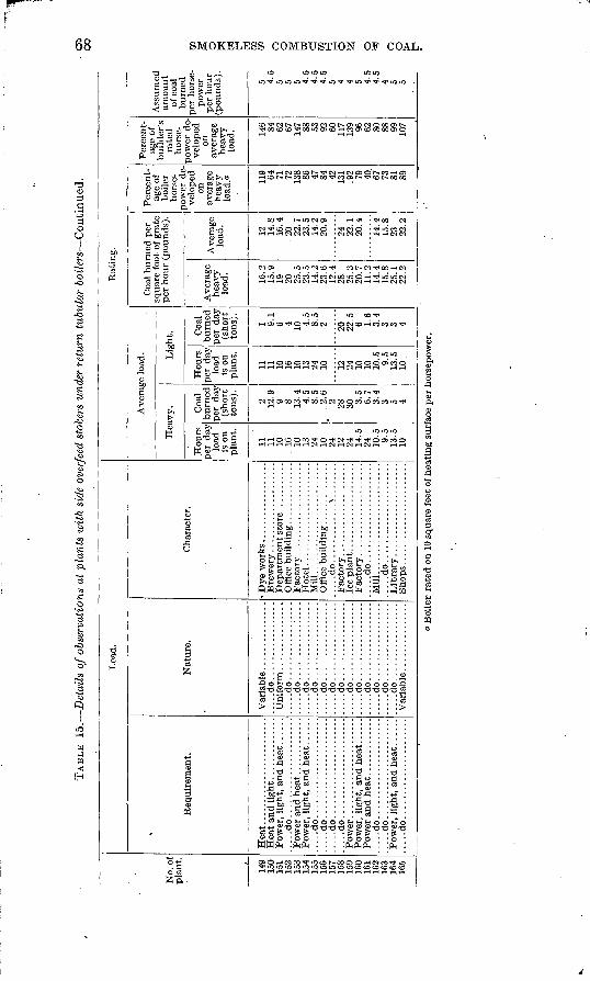
TAB
LE 15.
Det
ails
of
obse
rvat
ions
at
plan
ts w
ith
side
ove
rfee
d st
oker
s un
der
retu
rn t
ubul
ar b
oil
ers
Con
tinu
ed.
Oi
CO
No.
of
plan
t.
149
150
151
152
153
154
155
156
157
158
159
160
161
162
163
164
165
Loa
d.
Req
uire
men
t.
.....d
o......................
....
.do..
....
...........:
....
.....d
o......................
.....d
o......................
.....d
o......................
Nat
ure.
....
.do
....
....
....
....
.
....
.do
....
....
....
....
...
...d
o..
....
....
..:.
...
.....d
o.................
.....d
o.................
....
.do
....
....
....
....
......d
o.................
.....d
o.................
....
.do
....
....
....
....
...
...d
o..
....
....
....
...
....
.do
....
....
....
....
...
...d
o..
....
....
....
...
....
.do
....
....
....
....
...
...d
o..
....
....
....
...
Cha
ract
er.
Hot
el ...
....
....
....
....
....
Mill
.........................
Off
ice
buil
ding
..............
.....d
o......................
Mil
l...
....
....
....
....
....
.......d
o......................
Rat
ing.
. '
Ave
rage
load
.
Hea
vy.
Hou
rs
per
day
load
is
on
plan
t.
11
11
10
16
10
13
24
10
24
12
24
14.5
24
10
.5
9.5
13.5
10
Coa
l bu
rned
pe
r da
y (s
hort
to
ns).
2 12.9
9 8 13
.4
4.5
8.5
. 2.6
2 28
30
3.5
6.7
3.4
3 5 4
Lig
ht.
Hou
rs
per
day
load
is
on
plan
t.
11
11
10
16
10
13
24
10 12
24
10
10
10.5
9.
5 13
.5
10
Coa
l bu
rned
pe
r da
y (s
hort
to
ns). 1 9.1
6 4 10 4.5
8.5
2 20
22.5
6 1.
6 3.4
3 3 4
Coa
l bu
rned
per
sq
uare
foo
t of
gra
te
per
hour
(po
unds
).
Ave
rage
he
avy
load
.
16.2
15
.9
19
20
25.5
23
.5
14.2
23
.6
12.4
28
25
.3
20.7
11
.2
14.4
15
.8
25.1
22
.2
Av
erag
e lo
ad.
12
14.8
16
.4
20
22.7
23
.5
14.2
20
.9
24
22.1
20
.4
14.4
15
.8
23
22.2
Per
cent
ag
e of
bo
iler
hors
e2-
pow
er d
e
velo
ped
on
aver
age
heav
y lo
ad.o 11
9 64
71
72
138.
86
47
84
42
13
1 .9
2 79
40
67
73
81
89
Per
cent
ag
e of
bu
ilde
r's
rate
d ho
rse
po
wer
de
ve
lope
d on
av
erag
e he
avy
load
. 146 84
62
67
147 88
53
92
60
11
7 13
9 96
62
80
88
99
107
Ass
umed
am
ount
of
coa
l bu
rned
pe
r ho
rse
po
wer
pe
r ho
ur
(pou
nds)
.
5 4.5
5 5 5 4.5
4.5
4.5
5 4 4 5 4.5
4.5
4 5 5
a B
oile
r ra
ted
on 1
0 sq
uare
fee
t of
hea
ting
sur
face
per
hor
sepo
wer
.

TAB
LE 15.
Det
ails
of
obse
rvat
ions
at
plan
ts w
ith
side
ove
rfee
d st
oker
s un
der
retu
rn t
ubula
r boil
ers
Conti
nued
.
No.
of
pla
nt.
120
121
122
123
124
125
126
127
128
129
130
131
132
133
134
135
136
137
138
139
140
141
142
143
144
145
Sto
kin
g.
Thi
ck
ness
of
fire
(i
nche
s). 4
3-4
3-6
4-5 6
3-4 5 4 3 4 3 4
4-6 5 4 4 5
5-6
4-5 4
4-6
6-7 4
4-6
3-5
Fre
quen
cy o
f cl
eani
ng f
ire.
3 ti
mes
in
24 h
ours
...
.
.....d
o................
3 to
4 ti
mes
in 2
4 ho
urs.
.....d
o................
.....d
o................
.....d
o................
.....d
o..'. .............
.....d
o................
.....d
o................
.....d
o................
.....d
o................
.....d
o................
......do................
.....d
o................
.....d
o................
.....d
o................
.....d
o................
.....d
o................
Boi
lers
.
Typ
e
.....d
o................
.....d
o................
.....d
o................
.....d
o................
,.... do..
...
....
....
...
.....d
o................
.....d
o................
.....d
o................
.....d
o................
.....d
o................
....
.do
....
:...
....
....
.....d
o................
.....d
o................
.....d
o................
.....d
o. ...............
.....d
o................
.....d
o................
.....d
o................
(2 r
eturn
tubula
r. ......
.....d
o................
.....d
o................
.....d
o................
Size
.
1 48
" x
14',
32
3J"
tu
bes;
6
48"
x 1
6', 3
2 3J"
tub
es;
2 42
" x
16',
28 3
i" t
ubes
.
1 66
" x
16',
54 4
" tu
bes;
1 6
0"
x IS
', 42
4"
tube
s.
3 66
" x
16',
64 4
" tu
bes;
1 6
6"
x 14
', 72
3*"
tub
es.
72
"xl8
' 72
4"
tubes.
.........
66"
x IS
' 56
4"
tub
es. .
........
3 60
" x
16',
48 4
" tu
bes;
1 7
2"
x IS
', 90
3i"
tub
es.
2 60
" x
18',
72 4
" tu
bes;
1 9
0 4"
x 1
6' t
ubes
; 1
10S
4" x
16'
tu
bes;
1 1
20 4
" x
16'
tube
s.
3 60
" x
IS',
36 4
£" t
ubes
; 1
72"
x IS
', 60
4i"
tub
es.
62"
x 16'.............. ........
60"
x 1
6'.
44 4
" tu
bes.
.........
Num
ber
in
st
alle
d. 9 9 4 4 2 3 2 4 3 3 3 2 1 1 4 3 4 4 3
> 4 4 3 4 2 3
Num
ber
use
d to
carr
y-
Ave
r
age
hea
vy
lo
ad. 7 7 2 2
2 2 1 4 3 2 2 1 1 1 2 2 3 4 2 3 2 4 2 4 2 3
Ave
r
age
light
load
. 9 5 2 2 2 2 1 4 2 2 2 1 1 1 2 3 4 2 2 2 4 2 3
Buil
der
's
rate
d
hors
e
pow
er.
120
60,
65,
75 90
80
125 80
93,8
3
100 65
20
0 15
0 15
0 15
0 10
0 15
0 20
0 12
5 10
0, 1
50 100
1125
, 20
0 \
224
150
So,
150
120 SO
15
0 10
0
Hor
se
pow
er
ooil
er
rate
d on
10
squ
are
feet
of
heat
ing
surf
ace. 155
49,
55 83
94
147 94
106,
94
126,
109 51
20
0 15
9 15
9 15
9 12
4 17
8 22
5 10
7 95
, 17
6
.122
15
8, 1
68
201,
224 14
7 10
8,
146
122
125 87
Hea
ting
su
rfac
e (s
quar
e fe
et). 1,
550
490,
550
830
940
1, 4
70
940
1,06
0, 9
35
1,26
0, 1
,085 50
5 2,
000
1,59
0 1,
590
1,59
0 1,
240
1,78
5 2,
250
1,06
5 95
0, 1
,760
1,22
0 1,
580,
1,6
75
2,01
0, 2
,235
1,47
0 1,
080,
1,4
60
1,22
0
1,25
0 87
0
Sup
erhe
at
ing
surf
ace
(squ
are
feet
).
0 0 0 0 0 0 0 0 0 0 0 0 0 0 0 0 0 0 0
} « 0 0 0 0 0 0
Ste
am
pres
su
re a
t ga
ge. 10
0 10
0
120 90
11
0 85
85,9
0 80 70
100
105 90
SO
SO
100
120
. 110
90
-100 10
0 16
0
100
100
95 90
12
0 10
0
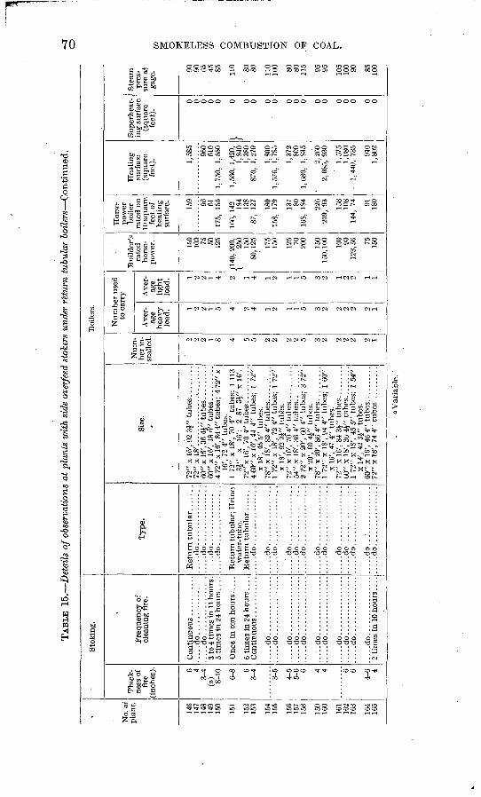
TAB
LE 1
5.
Det
ails
of o
bser
vatio
ns a
t pl
ants
with
sid
e ov
erfe
ed s
toke
rs u
nder
r'e
turn
tub
ular
boil
ers
Con
tinu
ed.
No.
of
pla
nt.
146
147
148
149
150
151
152
153
154
155
156
157
158
159
160
161
162
163
164
165
Sto
king
.
Thi
ck
ness
of
fire
(i
nche
s). 6 4
3-4
(a) 8-10 6-
8 6 3-
4
3-5
4-5
5-6 6 4 4 6 6
4-6 4
Fre
qu
ency
of
clea
ning
fir
e.
....
.do
....
....
....
....
.....d
o..
....
....
....
..3
to 4
tim
es h
i 11
hours
.
Onc
e in
ten
hou
rs ...
..
6 ti
mes
in
24 h
ours
...
.
....
.do
....
....
....
....
....
.do
....
....
....
....
.....d
o................
....
.do
....
....
....
....
....
.do
.. ...
....
....
...
.....d
o..
....
....
....
.......d
o..
....
....
....
..
.....d
o................
....
.do
....
....
....
....
....
.do
....
....
....
....
.....d
o................
Boi
lers
.
Typ
e.
.....d
o................
....
.do
....
....
....
....
....
.do
....
....
....
....
....
.do
....
....
....
....
Ret
urn
tubula
r; H
ein
e w
ater
-tub
e.
....
.do
....
....
....
....
....
.do
....
....
....
....
....
.do
....
....
....
....
.....d
o................
....
.do
....
....
....
....
....
.do
....
....
....
....
....
.do
....
....
....
....
....
.do
....
....
....
....
....
.do
....
....
....
....
....
.do
....
....
....
....
.....d
o...............
.
.....d
o..:.
............
....
.do
....
....
....
....
Size
.
72"
x 16
', 92
3£"
tub
es ........
72"
x I
S'
60"
x 16
', 36
4|"
tub
es ...
....
..60
" x
16',
18 6
" tu
bes
. ........
4 72
" x
16',
84 4
" tu
bes;
4 7
2" x
16
', 72
4"
tube
s.
1 72
" x
18',
70 4
" tu
bes;
1 1
13
3£"
x 16
'; 2
87 3i"
x 1
6'.
72"x
l6',
70 4
" tu
bes..
....
....
4 60
" x 1
6', 4
4 4"
tub
es;
1 72
" x
18',
45 5
" tu
bes.
78
" x
18',
82 4
" tu
bes.
.........
1 72
" x
18',
72 4
" tu
bes;
1 7
2"
x 18
', 92
3£"
tub
es.
72"
x 16
', 70
4"
tube
s. .........
2 72
" x 2
0',
60 4
" tu
bes;
3 7
2"
x 2
0',
60 4
V t
ubes
. 78
" x
20',
86" 4
" tu
bes
. ........
1 72
" x
18',
94 4
" tu
bes;
1 6
0"
x 16
', 47
4"
tube
s.
72"
x 16
', 84
3}"
tub
es. .
....
...
60"
x 18
', 36
4i"
tub
es. .
.......
1 72
" x
18',
45 5
" tu
bes:
1 5
4"
x 14
', 42
3i"
tub
es.
60"
x 1
6',
46 4
" tu
bes.
.........
Num
be
r in
st
alle
d. 2 2 2 1 8 4 5 5 2 2 2 2 5 3 2 2 2 2 2 1
Nu
mb
er u
sed
to c
arry
Ave
r
age
heav
y lo
ad. 1 2 2 1 5 4 2 4 1 2 1 1 5 3 2 2 2 2 2 1
Ave
r
age
ligh
t lo
ad. 1 2 2 1 4 2 1 4 1 2 1 1 5 3 2 1 2 2 1 1
Bui
lder
's
rate
d ho
rse
po
wer
.
150
100 75
50
125
/140
, 20
0,
\ 25
0 15
0 80
,125 17
5 15
0
125 70
20
0
150
150,
100 10
0 90
123,
56 75
15
0
Hor
se
pow
er
boil
er
rate
d on
10
squ
are
feet
of
heat
ing
surf
ace. 15
9 96
61
175,
15
5
166,
142
18
4 13
8 87
, 12
7
180
158,
17
9
137 80
16
8, 1
84 226
209,
93
158
108
144,
74 91
18
0
Hea
tin
g
surf
ace
(squ
are
feet
). 1,58
5
960
610
1,75
0,
1,55
0
1,56
0, 1
,420
, 1,
840
1,38
0 87
0, 1
,270
1,80
0 1,
576,
1,
785
1,37
2 80
0 1,
680,
1,
835
2,26
0 2,
085,
930
1,57
5 1,
080
1,
440,
73
5
910
1,80
2
Sup
erhe
at
ing
surf
ace
(squ
are
feet
).
0 0 0 0 0
}0 0 0 0 0 0 0 0 0 0 0 0 0 0
Ste
am
pres
su
re a
t ga
ge. 90
90
65
45
85 11
0
' 80
80 11
0 10
0 80
80
115 95
95 105
100 90 85
100
a V
aria
ble
.
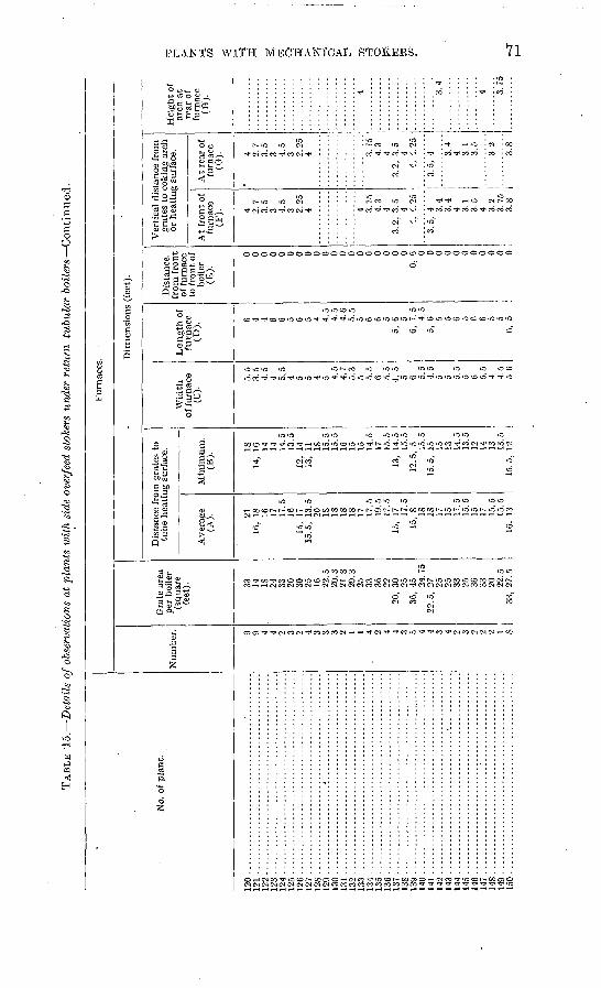
TAB
LE 1
5.
Det
ails
of
obse
rvat
ions
at
plan
ts w
ith
side
ove
rfee
d st
oker
s un
der
retu
rn t
ubul
ar b
oil
ers
Co
nti
nu
ed.
No.
of
plan
t.
120 ..
................
...........................
121 .............................................
122 .............................................
1 93
124 .............................................
125 ..
....
....
....
....
....
....
....
....
....
....
...
126 ..
....
....
....
....
....
....
....
....
....
....
...
131
133 .............................................
134 .............................................
136 -..........-.......-
......-...........-
----..
138 ..................
....
....
....
....
....
....
...
i q
o
140 .............................................
142 .............................................
1 d
^
145 .............................................
1 45
2
149
150 .............................................
Fur
nace
s.
Num
ber. 9 9 4 4 2 3 2 4 3 3 3 2 1 1 4 9 4 4 3 5 4 4 3 4 2 3 2 2 9 1 S
Gra
te a
rea
per
boil
er
(squ
are,
fe
et). 33
14
^
IS
24
33
20
30
25
16
22.5
20
.3
21.8
29
.3
25
33
36
22
20,
30
25
36,
45
24.7
5 22
.5,
27
25
25
33
25
36
33
20
22.5
33
, 27
.5
Dim
ensi
ons
(fee
t).
Dis
tanc
e fr
om g
rate
s to
tu
be
heat
ing
surf
ace.
Ave
rage
(A
). 21
16,
18
16
17
17.5
16
15
, 17
15
.5,
13.5
20
IS
IS
IS
IS
17
17
.5
19.5
17
.5
15,
17
17.5
lo
, 8 IS
IS
17
15
17
.5
15.5
15
17
15
.5
15.5
16
, 13
Min
imum
. (B
).
18
14,
16
14
14
14.5
13
.5
12,
14
13,
11
IS
15.5
15
.5
16
15
15
14.5
17
15
. 5
13,
14.5
15
.5
12.5
, 5 15
.5
15.5
, 15
15
13
14
.5
13.5
12
14
13
13
.5
15.5
, 12
Wid
th
of f
urna
ce
(C).
5.5
3.5
4.5
4 5. 5
4 5 5 4 5 4.
5 4.
7 5.
3 5 5.
5
6.
0.0
4, 5
5 6 5.
5 4.
5 5 5 5.
5 5 6 5.
5 4 4.
5 5.
6
Len
gth
of
furn
ace
(D).
6 4 4 6 6 5 6 5 4 4.5
4.5
4.6
5.5
5 6 6 5 5,
6 5
6, 7
.5
4.5
5, 6
5 5 6 5 6 6 5 5 6,
5
Dis
tanc
e,
from
fro
nt
of f
urna
ce
to f
ront
of
boil
er
(E).
0 0 0 0 0 0 0 0 0 0 0 0 0 0 0 0 0 0 0 0,
6 0 0 0 0 0 0 0 0 0 0 0
\rer
tica
l di
stan
ce f
rom
gr
ates
to
coki
ng a
rch
or h
eati
ng s
urfa
ce.
At
fron
t of
fu
rnac
e (F
). 4 2.7
3.5
3 4.5
3 2.25
4 4 3.
75
4.3
4 3.
2, 3
.5
4 '.,
<.2
5
3.5,
4 3.
4 3.
4 4 3.
1 3.
5 4 3.
2 3.
75
3.8
At
rear
of
furn
ace
(G). 4 2.
7 3.
5 3 4.
5 3 2.
25
4
Hei
gh
t of
ar
ch a
t re
ar o
f fu
rnac
e (H
).
i
3.75
4.
3 4
3.2,
3.5
4
4, 4
.25
3.5,
4 3.4
4 3.
1 3.
5
3.2
3.S
4 3.4 4 3.75
O- a
>
t* GO-
H- O
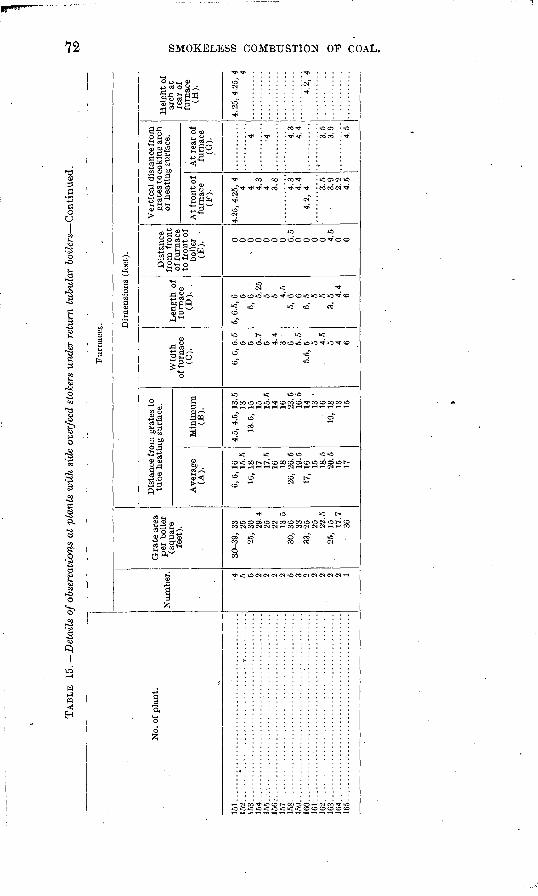
TA
BL
E 15.
Det
ails
of o
bser
vati
ons
at p
lant
s w
ith
side
ove
rfee
d st
oker
s un
der
retu
rn t
ubul
ar b
oil
ers
Co
nti
nu
ed.
No.
of
plan
t.
151..............................................
15
3..
....
....
....
....
....
....
....
....
....
....
....
154.
...
....
....
....
....
....
....
....
....
....
....
..15
5 ..............................................
15
6..
....
....
....
....
....
....
....
....
....
....
....
157:.
............................................
158.
.............................................
159.
.............................................
160.
..............................................
16
1..
....
....
....
....
....
....
....
....
....
....
....
162..............................................
16
3..
....
....
....
....
....
...:
....
....
....
....
....
164
.............................................
165..............................................
Fu
rnac
es.
Num
ber. 4 5 5 2 2 2 2 5 3 2 2 2 2 2 1
Gra
te a
rea
per
boi
ler
(squ
are
feet
).
30-3
9, 3
3 25
25,
30
29.4
25
22
13
.5
30,
36
33
33,
25
25
22.5
25
, 15
17
.7
36
Dim
ensi
ons
(fee
t).
Dis
tanc
e fr
om g
rate
s to
tu
be h
eati
ng s
urfa
ce.
Ave
rage
(A
).
6, 6
, 16
15
.5
16,
18
17
17.5
16
18
26
, 26
.5
19.5
17
, 16
15
18
.5
20.5
15
17
Min
imum
(B
).
4.5,
4.5
, 13
. 5
13
13.5
, 15
15
15
.5
14
16
23.5
16
.5
14
13
' 16
19
, 18
13
15
Wid
th
of f
urn
ace
(C).
6, 6
, 5.
5
5 5 5.7
5 4
.4
3 6 5.5
5.
5, 5
5 4.5
5 4 6
Len
gth
of
furn
ace
(D).
.
5, 6
.5,
6 5 5,
6 5.25
5 5 4
.5
5, 6
6 6,
5 5 5
3, 5
4.4
6
Dis
tanc
e fr
om f
ront
of
fur
nace
to
fro
nt o
f bo
iler
(E).
0 0 -
0 0 0 0 0 6.5
0 0 0 0 4.
5 0 0
Ver
tica
l di
stan
ce fr
om
grat
es to
cok
ing
arch
or
hea
ting
sur
face
.
At
fron
t of
furn
ace
(F).
4.25
, 4.
25,
4 4 4 4.3
4 3.8
4.3
4.4
4.
2, 4 3
.5
3.9
2.2
4.5
At
rear
of
furn
ace
(G). 4 4 4.
34.4
3.5
3.9
4.5
Hei
ght
of
arch
at
rear
of
furn
ace
(H).
4.2
5,4
.25
, 4 4
4.2,
4
O W B
f*
td 03 O g W
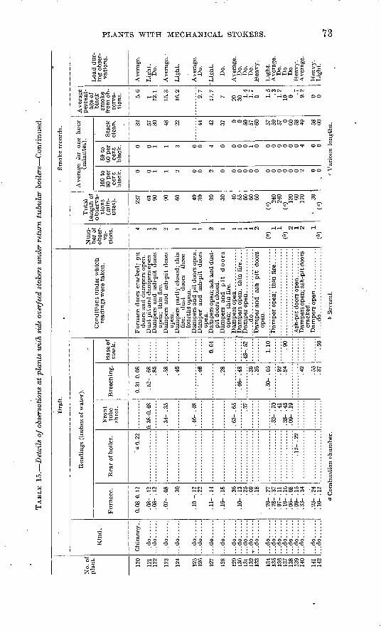
TAB
LE 15.
Det
ails
of
obse
rvat
ions
at
plan
ts w
ith
side
ove
rfee
d st
oker
s un
der
retu
rn t
ubula
r b
oil
ers
Con
tinu
ed.
No.
of
pla
nt.
120
121
122
123
124
125
126
127
128
129
130
131
132
133
134
135
136
137
138
139
140
141
142
Dra
ft.
Kin
d.
Chi
mne
y..
...d
o..
....
..
.do
....
..
...d
o..
....
...d
o..
....
...d
o......
...d
o..
....
...d
o......
...d
o..
....
...d
o..
....
...d
o..
....
...d
o..
....
,..d
o......
..d
o..
....
...d
o......
...d
o:.
....
...d
o......
...d
o......
...d
o..
....
...d
o..
....
...d
o..
....
...d
o..
....
...d
o..
....
Rea
ding
s (i
nche
s of
wat
er).
Fur
nace
.
0. 0
8-0.
12
. 08-
. 1
2 . 0
8- .
12
.07-
.08 .3Q
. 10
-. 1
2.2
2
.11-
.14
. 16-
. I
S
.36
.10-
.13
.25
.09
.18
. 20-
. 2
7.2
8-
.37
. 07-
. 1
1.1
0-
.16
.06-
.08
.09-
.15
.33-
.34
.23-
.24
. 10-
. 1
2
Rea
r of
boi
ler.
' a. o
. 22
.12
- .2
2
Fro
nt
tub
e sh
eet.
0. 3
8-0.
48
. 34-
. 3
5
. 46-
. 4
8
. 63-
. 6
5
.37
.41
. 38-
. 4
5 .0
9-
.19
Bre
echin
g.
0. 3
1-0.
68
. 52-
. 6
8 .8
5
.58
.46
.46
.28
.46-
.48
.36
.35
.50-
.65
.92
.84
.42
.55
.37
Bas
e of
st
ack
.
0.64
. 48-
. 52
1.10 .90
.50
Co
nd
itio
ns
under
whic
h
read
ings
wer
e ta
ken
.
Fu
rnac
e do
ors
crac
ked
; p
it
door
s an
d d
amp
ers
open
. D
ust
pit
an
d d
amp
ers
op
en.
. D
amper
s an
d as
h-p
it d
oors
op
en;
thin
fir
e.
Dam
per
s an
d a
sh-p
it d
oors
open
. D
amper
s part
ly c
lose
d; t
hin
fi
re;
du
st
door
s th
ree-
fo
urt
hs
open
. D
amper
s an
d p
it d
oo
rs o
pen
. D
amper
an
d
ash-p
it
door
s open
. D
amp
ers
op
en;
ash a
nd d
ust
- p
it d
oors
clo
sed.
D
amper
s an
d
pit
d
oo
rs
op
en;
thin
fir
e.
' D
amper
s o
pen
; th
in f
ire.
. . .
.....d
o......................
Dam
per
an
d
ash
pit
d
oo
rs
op
en.
Dam
per
s o
pen
; as
h-p
it d
oors
cr
acked
.
.....d
o......................
Sm
oke
reco
rds.
Num
ber
of
obse
r- .
va-
tions. 4 1 2 2 1 1 i 2 1 1 1 1 1 2
(6)
(\ 1 2 1
W
Tota
l le
ng
th o
f obse
rva
ti
ons
(min
ute
s). 237 61
90 90
60 40
30 90
30 40
55
60
60
60
(«) 24
0 24
0(«
) 120 60
170 30
(<
0
Av
erag
e fo
r one
hour
(min
ute
s).
100
to
SO p
er
cent
bla
ck. 0 0 1 1 2 0 0 2 0 0 0 0 0 0 0 0 0 0 0 0 2 0
. 0
SO t
o
60 p
er
cent
bla
ck. 0 0 1 1 3 0 0 4 0 0 0 0 1 0 0 0 0 0 0 0 4 0 0
Sta
ck
clea
n. 32 57
30 48
22 44
42
37 0 0 50
57
'60 57
59
57
0 60
58
49 58
60
Av
erag
e per
cent
ag
e of
bla
ck
smo
ke
fro
m o
b
serv
a
tions. 5.
6
1 12,1
15.3
16.2
2.7
17.7
7 20
30 1.4
1.7
0 1.5 .3
1.2
10 0 .7
9.
2
0 0
Lo
ad d
ur
in
g o
bser
v
atio
ns.
Aver
age.
Lig
ht.
D
o.
Aver
age.
Lig
ht.
Aver
age.
D
o.
Lig
ht.
Do.
Aver
age.
D
o.
Do.
D
o.
Hea
vy
.
Lig
ht.
A
ver
age.
D
o.
Do.
D
o.
Hea
vy
. A
ver
age.
Hea
vy.
Lig
ht.
fcj
o W o
<J C
om
bust
ion c
ham
ber
.6
Sev
eral
.<
Var
iou
s le
ng
ths.
CO
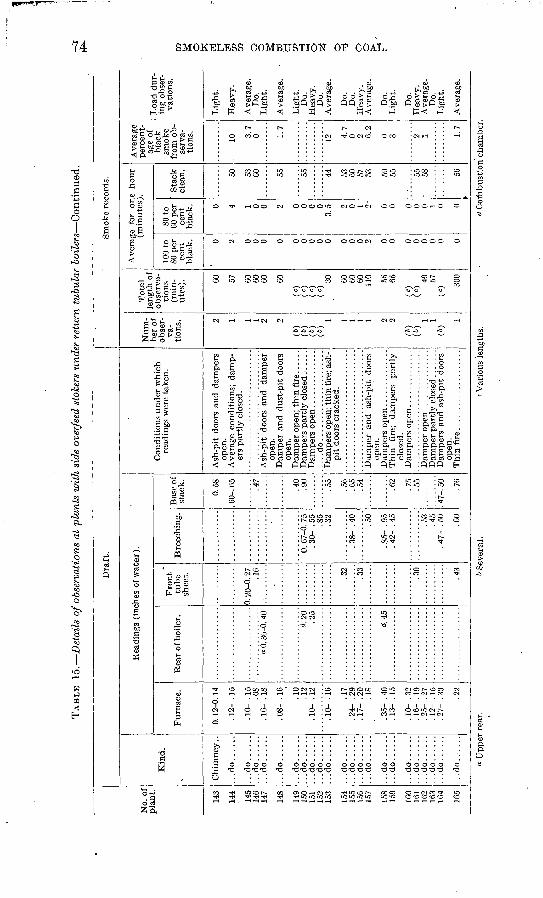
TAB
LE 15.
Det
ails
of o
bser
vatio
ns a
t pl
ants
wit
h si
de o
verf
eed
stok
ers
unde
r re
turn
tub
ular
boil
ers
Con
tinu
ed.
No.
of
pla
nt.
143
144
145
146
147
148
149
150
151
152
153
154
155
156
157
158
159
160
161
162
1631
164
165
Dra
ft.
Kin
d.
...d
o......
...d
o......
...d
o......
...d
o......
...d
o......
...d
o......
...d
o......
...d
o......
...d
o......
...d
o......
...d
o......
...d
o......
...d
o......
...d
o......
...d
o......
...d
o......
...d
o......
...d
o......
...d
o......
...d
o......
...d
o......
...d
o......
Rea
ding
s (i
nche
s of
wat
er).
Fu
rnac
e.
0. 1
2-0.
14
. 12-
. 1
5
. 10-
. 1
5.O
S . 1
6- .
18
. 08-
. 1
6
.10
.12
.10-
.12
.10-
.16 .1
7 .2
4- .
29.1
7- .
20 .18
. 35-
. 4
0 .1
3- .
15
.10-
.32
. 16-
. 1
9.2
5- .
27. 1
2- .
15
.27-
.30 .22
Rea
r of
boi
ler.
a 0.
36-
0. 4
0
d.20
.2
5
d.45
Fro
nt
tub
e sh
eet.
0. 2
0-0.
27
.16
.32
.33
.30
.43
Bre
echi
ng.
6. 6
7^6.
75
. 30-
. 5
5.8
5 .3
2
. 38-
. 4
0
.50
. 85-
. 9
5.4
2-
.45
.53
.45
. 47-
. 5
0
.GO
Bas
e of
stac
k.
0.58
. 60-
. 65
.47
.40
.90
.55
.56
.65
.54
.62
.75
. 47-
. 50
.76
Con
diti
ons
under
whi
ch
read
ings
wer
e ta
ken.
Ash
-pit
doo
rs a
nd d
ampe
rs
open
. A
vera
ge c
ondi
tion
s; d
amp
ers
par
tly
clo
sed.
Ash
-pit
do
ors
and
dam
per
open
. D
ampe
r an
d d
ust
-pit
doo
rs
open
.
.....d
o... ...................
Dam
pers
ope
n; t
hin
fir
e; a
sh
pit
doo
rs c
rack
ed.
Dam
per
and
ash-
pit
door
s op
en.
Thi
n fi
re;
dam
pers
par
tly
clos
ed.
Dam
pers
and
ash
-pit
doo
rs
open
.
Sm
oke
reco
rds.
Num
be
r of
ob
ser
va
ti
ons. 2 1 1 1 2 2
(6)
(fc)
(6)
(")
1 1 1 1 2 2
(») (b> i i
(b)i
To
tal
leng
th o
f ob
serv
a
tion
s (m
in
utes
). 60
57 60
60
60 60
(c)
(c)
(c)
(c)
30 60
60
60
110 55
65
(c)
(c)
40
57
(c) 30
0
Ave
rage
fo
r on
e h
ou
r (m
inu
tes)
.
100
to
80 p
er
cent
blac
k. 0 2 0 0 0 0 0 0 0 0 0 0 0 0 2 0 0 0 0 0 0 0 0
80 t
o 60
per
ce
nt
blac
k. 0 4 1 0 0 2 0 0 0 0 3.
5 2 0 1 2- 0 0 0 0 0 1 0 0
Sta
ck
clea
n. 50 53
60 55 55 44 53
60
57
53 59
55 55 58 56
Ave
rage
pe
rcen
t
age
of
blac
k sm
oke
from
ob
se
rva
ti
ons. 10 3.
7 0 1.
7
12 4.7
0 2 6.2
0 3 2 1 1.7
Loa
d du
r
ing
obse
r
vati
ons.
Lig
ht.
Hea
vy.
Ave
rage
. D
o.
Lig
ht.
Ave
rage
.
Lig
ht.
Do.
H
eavy
. D
o.
Ave
rage
.
Do.
D
o.
Hea
vy.
Ave
rage
.
Do.
L
ight
.
Do.
Hea
vy.
Ave
rage
. D
o.
Lig
ht.
Ave
rage
.
a*
CO CO H o o
a U
pp
er r
ear.
& S
ever
al.
c Var
ious
len
gths
.d
Com
bust
ion
cham
ber.
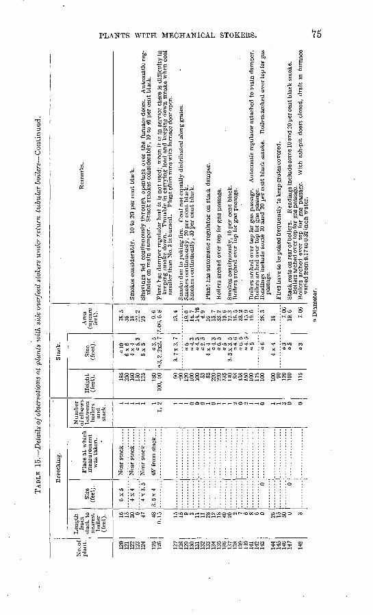
TAB
LE 15.
Det
ails
of o
bser
vati
ons
at p
lant
s w
ith
side
ove
rfee
d st
oker
s un
der
retu
rn t
ub
ula
r boil
ers
Co
nti
nu
ed.
No.
of
pla
nt.
120
121
122
123
124
125
126
127
128
129
130
131
132
133
134
135
136
137
138
139
140
141
142
143
144
145
146
147
148
Bre
echi
ng.
Len
gth
from
st
ack
to
near
est
boile
r (f
eet)
. 16
15
30 0 47 48
0.1
5 15
15 9 3 11
11
28
12
IS
40
20
7 6 8 6 0 26
15
50 0 3
Siz
e (f
eet)
.
6x5
4x4
4x3.5
3. 5
x 4
0 0
..........
Pla
ce a
t w
hich
m
easu
rem
ent
was
tak
en.
45' f
rom
sta
ck..
.
Num
ber
of e
lbow
s be
twee
n bo
ilers
an
d st
ack.
1 1 1 1 1 1 1,
2
1 1 1 0 0 0 1 0 1 1 1 2 0 2 1 1 0 1 1 3 0 0
Sta
ck.
Hei
ght
(fee
t).
185
230
ICO
15
0 12
5
180
100,
90 90
*9
0 12
0 10
0 10
0 53
85
220-
22
0 13
5 14
0 88
138
150
100
175
100
100 90
12
0 10
0
115
Siz
e (f
eet)
.
a 10
6
x6
4x4
o5.3
5x5 o3.5
a3
,2.2
x2.
7
3.7
x3.7
°5
a4.3
a
4. 3
a
2. 5
4x4
a 4.
3
06.0
o5
3.5
x3.5
a
4. 6
"6
.5
a 4.
5
05 06
4x
4 o3
o5
Are
a (s
quar
e fe
et).
78.5
36
16
22
.2
25 9.6
7.0
6,5
.8
13.4
19.6
14
.7
14.7
6 4.
9 16
15
.7
33.2
19
.6
12.3
16
.5
33.2
15
.9
19.6
28.3
1C 7.06
19
.6 7.06
Rem
arks.
Smok
es c
onsi
dera
bly.
10
to
20 p
er c
ent
blac
k.
Shav
ings
fed
con
tinu
ousl
y th
rough o
peni
ngs
over
the
fur
nace
-doo
rs.
Aut
omat
ic r
eg
ulat
or o
n m
ain
dam
per.
S
tack
sm
okes
con
side
rabl
y, 1
0 to
40
per
cent
bla
ck.
Pla
nt h
as d
ampe
r re
gula
tor
but
it i
s no
t us
ed:
whe
n it
is
in s
ervi
ce t
here
is
diff
icul
ty in
ke
epin
g sm
oke
dow
n.
Tro
uble
. in
carr
ying
loa
d an
d ke
epin
g do
wn
smok
e w
hen
coal
sm
alle
r th
an N
o. 3
is b
urne
d.
Pla
nt o
ften
run
s w
ith
furn
ace
door
ope
n.
Smok
e du
e to
pok
ing
fire
. C
oal
not
equa
lly
dist
ribu
ted
alon
g gr
ates
. Sm
okes
con
tinu
ousl
y, 2
0 pe
r ce
nt
blac
k.
Smok
es c
onti
nuou
sly,
30
per
cen
t bl
ack.
Pla
nt h
as a
utom
atic
reg
ulat
or o
n st
ack
dam
per.
Boi
lers
arc
hed
over
top
for
gas
pas
sage
.
Smok
es c
onti
nuou
sly,
10
per
cent
bla
ck.
Boi
lers
arc
hed
over
top
for
gas
pas
sage
.
Boi
lers
arc
hed
over
top
for
gas
pas
sage
. A
utom
atic
reg
ulat
or a
ttac
hed
to m
ain
dam
per.
B
oile
rs a
rche
d ov
er t
op f
or g
as p
assa
ge.
Rea
ding
s in
clud
e so
me
10 a
nd 2
0 pe
r ce
nt b
lack
sm
oke.
B
oile
rs a
rche
d ov
er to
p fo
r ga
s pa
ssag
e.
Fire
s ha
ve to
be
poke
d fr
eque
ntly
to k
eep
grat
es c
over
ed.
Sta
ck re
sts
on r
ear o
f boi
lers
. R
eadi
ngs
incl
ude
som
e 10
and
20
per c
ent b
lack
sm
oke.
B
oile
rs a
rche
d ov
er to
p fo
r ga
s pa
ssag
e.
Boi
lers
arc
hed
over
top
for
gas
pas
sage
. W
ith
ash-
pit
door
s cl
osed
, dr
aft
in f
urna
ce
vari
ed f
rom
0.1
7 to
0.3
2 in
ch w
ater
.
O W o >
tr4 o> (-3
O
W
a D
iam
eter
.
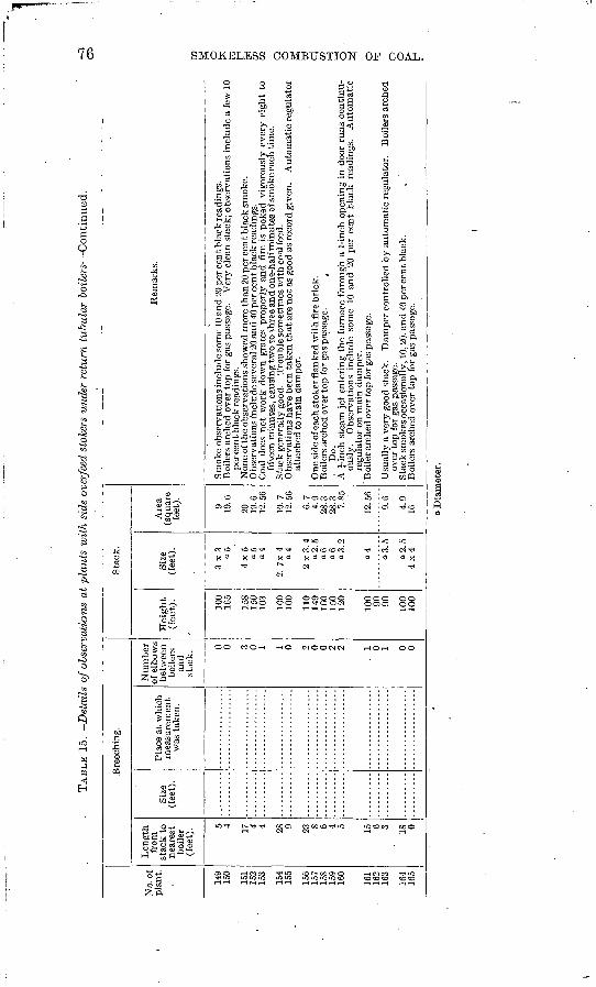
TAB
LE 1
5.
Det
ails
of o
bser
vati
ons
at p
lant
s w
ith
side
ove
rfee
d st
oker
s un
der
retu
rn t
ubul
ar b
oile
rs C
on
tin
ued
.
No.
of
pla
nt.
149
150
151
152
153
154
155
156
157
158
159
160
161
162
163
164
165
Bre
echi
ng.
Len
gth
from
st
ack
to
near
est
boile
r (f
eet)
. 5 4 17 4 4 28 9 23 8 6 4 5 15 6 3 18 0
Size
(f
eet)
.P
lace
at
whi
ch
mea
sure
men
t w
as t
aken
.
Nu
mb
er
of e
lbow
s be
twee
n bo
iler
s an
d st
ack.
0 0 3 0 1 1 0 2 0 0 2 2
. 1 0 1 0 0
Sta
ck.
Hei
ght
(fee
t).
100
165
158
150
103
100
100
110
149
ICO
15
0 12
0
100 90
90 100
100
Size
(f
eet)
.
3x
3
"5
4x5
«5 a4
2. 7
x 4
a4
2x3.4
a
2. 5
a6
a6
a
3. 2
a4 "3.5
o2.5
4x4
Are
a (s
quar
e fe
et). 9 19.6
20
19.6
12
.56
10.7
12
. 56
6.7
4.9
28.3
28
.3
7.85
12.5
6
9.6
4.9
16
Rem
arks
.
Smok
e ob
serv
atio
ns in
clud
e so
me
10 a
nd 2
0 pe
r cen
t bla
ck re
adin
gs.
Boi
lers
arc
hed
over
top
for
gas
pas
sage
. V
ery
clea
n st
ack;
obs
erva
tion
s in
clud
e a
few
10
per c
ent b
lack
rea
ding
s.
Non
e of
the
obse
rvat
ions
sho
wed
mor
e th
an 2
0 pe
r ce
nt b
lack
sm
oke.
O
bser
vati
ons
incl
ude
seve
ral 2
0 an
d 40
per
cen
t bla
ck re
adin
gs.
Coa
l do
es n
ot w
ork
dow
n gr
ates
pro
perl
y an
d fi
re i
s po
ked
vigo
rous
ly e
very
eig
ht t
o fi
ftee
n m
inut
es, c
ausi
ng tw
o to
thre
e an
d on
e-ha
lf m
inut
es o
f sm
oke
each
tim
e.
Sta
ck g
ener
ally
goo
d.
Tro
uble
som
etim
es w
ith
coal
fee
d.
Obs
erva
tion
s ha
ve b
een
take
n th
at a
re n
ot a
s go
od a
s re
cord
giv
en.
Aut
omat
ic r
egul
ator
at
tach
ed to
mai
n da
mpe
r.
One
sid
e of
eac
h st
oker
flan
ked
wit
h fi
re b
rick
. B
oile
rs a
rche
d ov
er to
p fo
r gas
pas
sage
. t
Do.
A
J-i
nch
stea
m j
et e
nter
ing
the
furn
ace
thro
ugh
a 1-
inch
ope
ning
in
door
run
s co
ntin
u
ousl
y.
Obs
erva
tion
s in
clud
e so
me
10 a
nd 2
0 pe
r ce
nt b
lack
rea
ding
s.
Aut
omat
ic
regu
lato
r on
mai
n da
mpe
r.
' Boi
ler a
rche
d ov
er to
p fo
r gas
pas
sage
.
Usu
ally
a v
ery
good
sta
ck.
Dam
per
cont
roll
ed b
y au
tom
atic
reg
ulat
or.
Boi
lers
arc
hed
over
top
for
gas
pas
sage
. S
tack
sm
okes
occ
asio
nally
, 10,
20,
and
40
per c
ent b
lack
. B
oile
rs a
rche
d ov
er t
op f
or g
as p
assa
ge.
a D
iam
eter
.
PLANTS WITH MECHANICAL STOKERS. 77
SUMMARY.
The importance of installing -the side-feed stoker with an arch over the entire grate can not be too strongly urged. At nearly every plant observed where this stoker had been installed with a short ignition arch only, trouble was experienced in keeping down smoke.
Some of the stacks having this stoker under them smoked badly because the fireman took advantage of the opening into the furnace and fired a part of the coal by hand.
There was some trouble in maintaining a. uniform feed of coal, at a few- of the plants visited. This seemed to happen when very fine coal was supplied. .With this stoker as ordinarily set, a banked fire can be maintained and the boiler thrown into service with only a small amount of smoke. The stoker has the valuable feature of a large coking plate area.
UNDERFEED STOKERS.
GENERAL DISCUSSION.
Stokers of the underfeed type differ radically from those described in the preceding pages. The fresh coal is forced into a horizontal retort, beneath that which has already ignited, and burns in a long heap that forms in the middle of the furnace. The unburned refuse is largely fused to a clinker, which slides down the sides of the heap and is hooked out by hand through the front of the furnace. The method of burning compels the use of mechanical draft, a fan being employed to force air through openings in tuyere blocks along the sides of the retort, at the level where the volatile hydrocarbons from the heap of burning coal are given off. Two makes of this stoker that have been put to the test of use under average power-plant conditions differ chiefly in the feeding mechanism and the device for handling the partly burned coal after it leaves the retort. In one pattern the coal is forced in continuously by a cone-shaped screw driven by a small steam engine, and the partly'burned coal falls on a flat grate through which air is drawn by a chimney. In the other pattern the coal is pushed beneath the burning heap in large charges, and the partly burned coal that rolls down the sides of the heap falls on a dead plate, where combustion is completed by the excess air that enters through tuyere openings. This method of burning coal has proved to be the better, and the plan of using air from the tuyeres for com plete combustion has been generally adopted as correct. The newer models of underfeed stokers are always installed with automatic con trol for coal and air.
In all underfeed stokers the air and the distilled gases are intimately mixed and intensely heated by rising through the incandescent coal, so that combustion is complete within a very short distance from the
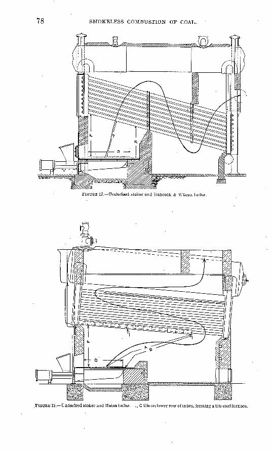
78 SMOKELESS COMBUSTION OF COAL.
FIGUKE 17. Underfeed stoker and Babcock & Wilcox boiler.
. FIGURE IS. Underfeed stoker and Heine boiler. 1, C tile on lower row of tubes, fonning a tile-roof furnace.
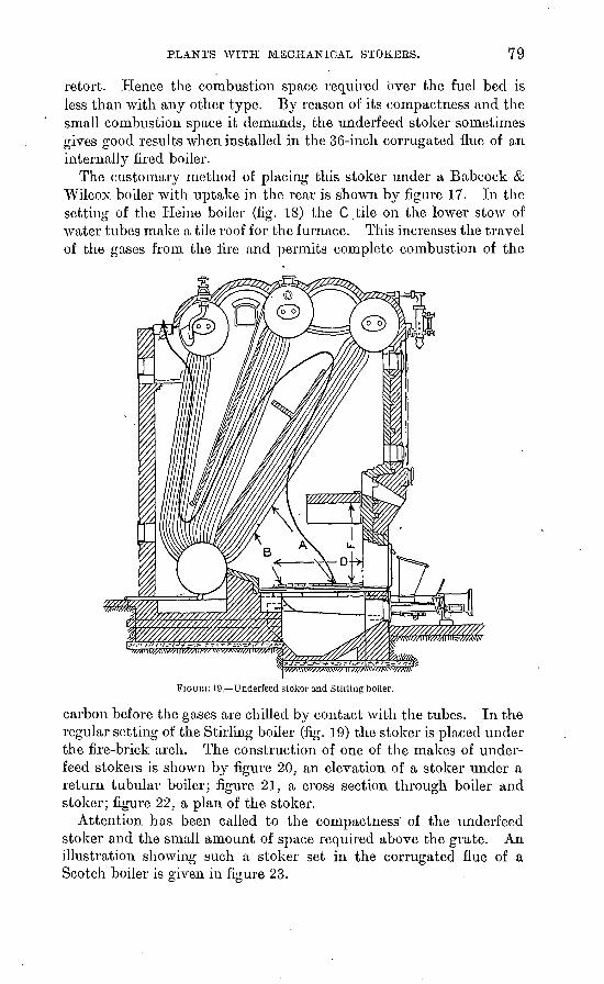
PLANTS WITH MECHANICAL STOKEES. 79
retort. Hence the combustion space required over the fuel bed is less than with any other type. By reason of its compactness and the small combustion space it demands, the underfeed stoker sometimes gives good results when installed in the 36-inch corrugated flue of anO O tJ
internally fired boiler.The customary method of placing this stoker under a Babcock &
Wilcox boiler with uptake in the rear is shown by figure 17. In the setting of the Heine boiler (fig. 18) the C .tile on the lower stow of water tubes make a tile roof for the furnace. This increases the travel of the gases from the fire and permits complete combustion of the
FIGURE 19. Underfeed stoker and Stirling boiler.
carbon before the gases are chilled by contact with the tubes. In the regular setting of the Stirling boiler (fig. 19) the stoker is placed under the fire-brick arch. The construction of one of the makes of under feed stokers is shown by figure 20, an elevation of a stoker under a return tubular boiler; figure 21, a cross section through boiler and stoker; figure 22, a plan of the stoker.
Attention has been called to the compactness' of the underfeed stoker and the small amount of space required above the grate. An illustration showing such a stoker set in the corrugated flue of a Scotch boiler is given in figure 23.
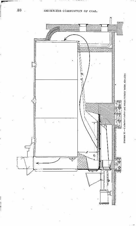
oo
o
FIG
UK
E 20
. Und
erfe
ed s
toke
r an
d re
turn
tub
ular
boi
ler,
ele
vati
on
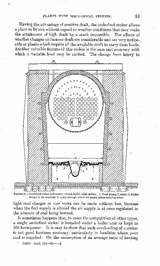
PLANTS WITH MECHANICAL. STOKERS. 81
Having the advantage of positive draft, the underfeed stoker allows a plant to be run without regard to weather conditions that may make the attainment of high draft by a stack impossible. The effects of weather changes on furnace draft are considerable and are very notice able at plants which require all the available draft to carry their loads. Another valuable feature of this stoker is the ease and economy with which a variable load may be carried. The change from he'avy to
oooooo oooooo oooooooooooo oooooo oooooo oooooooooooo oooooooooooo
FIGURE 21. Underfeed stoker and return tubular boiler, cross section. 1, Dead plates; 2, retort; 3, tuy6re blocks; 4, air chamber; 5, space through which air passes before entering retort.
light coal charges or vice versa can be made without loss, because when the fuel supply is altered the air supply is at once regulated to the amount of coal being burned.
It sometimes happens that, to meet the competition of other types, a single underfeed stoker is installed under a boiler unit as large as 200 horsepower. It is easy to show that such overloading of a stoker is not good business economy, particularly in localities where poor coal is supplied. On the assumption of an average ratio of heating
' 74897 Bull. 373 09 6
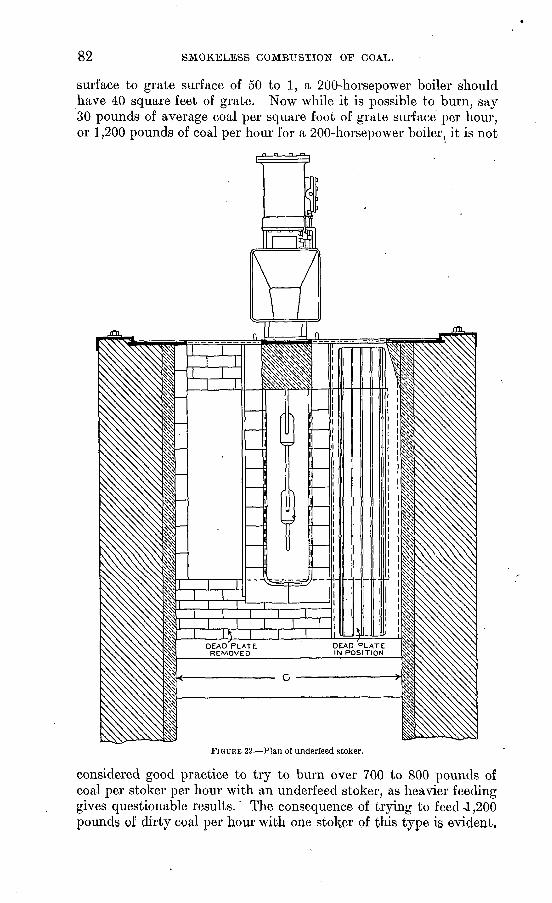
82 SMOKELESS COMBUSTION OF COAL.
surface to grate surface of 50 to 1, a 200-horsepower boiler should have 40 square feet of grate. Now while it is possible to burn, say 30 pounds of average coal per square foot of grate surface per hour, or 1,200 pounds of coal per hour for a 200-horsepower boiler, it is not
FIGURE 22. Plan of underfeed stoker.
considered good practice to try to burn over 700 to 800 pounds of coal per stoker per hour with an underfeed stoker, as heavier feeding gives questionable results.' The consequence of trying to feed 4,200 pounds of dirty coal per hour with one stoker of this type i§ evident.
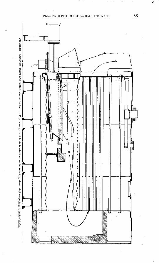
PLANTS WITH MECHANICAL STOKERS. 83
84 SMOKELESS COMBUSTION OF COAL.
It is the general opinion that it is harder to keep down smoke at the small hand-fired return tubular, boiler plant than anywhere else, but the underfeed stoker has replaced many hand-fired furnaces at such plants. The only variable element in the operation of this stoker, once it is correctly installed, is the cleaning of fires, l?ut if the fireman is careful to burn clown the fires before breaking them, up there will be no necessity of making smoke.
DETAILED DESCRIPTION OF PLANTS.
The underfeed type of stoker was found at 48 different plants in eight different States, the size of the plants ranging from 75 to 3,500 rated boiler horsepower. These plants burned coal from Illinois, Indiana, Kentucky, Ohio, Pennsylvania, and West Virginia, the cost of which.ranged from $1.03 to $2.75 per ton, the conditions at the different plants varying widely. The size of the boiler units ranged from 50 to 500 horsepower; at 33 plants the units were 200 horse power or less, and with two exceptions one stoker per boiler was installed at these plants. All but five of- the plants had automatic regulators for coal or air. But two of these stokers were set in a Dutch oven; this setting was used because the boilers were of the vertical type.
Plants with water-tube boilers. Underfeed stokers were found under water-tube boilers at 22 plants, at 4 of which the fuel was run-of-mine coal. At 13 plants the load carried was uniform, and at 9 it was variable. The thickness of fire ranged from 8 to 18 inches. The kind of coal burned is stated in the following summary:
Kind of coal burned at plants with underfeed stokers under water-tube boilers.
Number of plants, a.
Illinois.......................................................... 5Indiana......................................................... 1Kentucky...................................................... 1Ohio........................................................... 7Pennsylvania................................................... 8
- West Virginia.................................................... 1
Some averages of the observations at these plants are given below:
Difference of draft between ash pit and furnace, 3 inches of water.Coal as received burned per stoker per hour, average heavy load, 560 pounds;
extremes, 330 and 1,060 pounds.Percentage of rated boiler horsepower developed average heavy load (boiler rated on
10 square .feet of heating surface per horsepower), 92; extremes, 58 and 146.Average distance from grate to heating surface (dead plates to shell), 4.9 feet;
extremes, 3 and 7.5 feet.
a One plant burned both Ohio and Pennsylvania coal.
PLANTS WITH MECHANICAL STOKERS. 85
Least distance from grate to heating surface (dead plates to shell),.3.8 feet; extremes, 2 and 5.3 feet.
Smoke, black, 2.4 per cent. Average draft conditions: Pressure in ash pit, 17 plants, 2.45 inches of water; range,
I to 4 inches. Draft in furnace, 19 plants, 0.33 inch; range, 0.01 to 1 inch. Draft in rear of boiler, 13 plants, 0.48 inch; range, 0.17 to 1.07 inches. Draft at base of stack,II plants, 0.80 inch; range, 0.24 to 1.50 inches. The approximate pressure and drafts deduced from these readings are as follows: Pressure in ash pit, 2.50 inches of water; draft in furnace, 0.35 inch; draft at rear of boiler, 0.50 inch; draft at base of stack, 0.80 inch. This gives a drop of about 3 inches through the fuel bed, of about 0.15 inch through the boiler, and of 0.30 inch from the boiler to the stack.
Details of the observations at plants with underfeed stokers under water-tube boilers are given in Table 16.
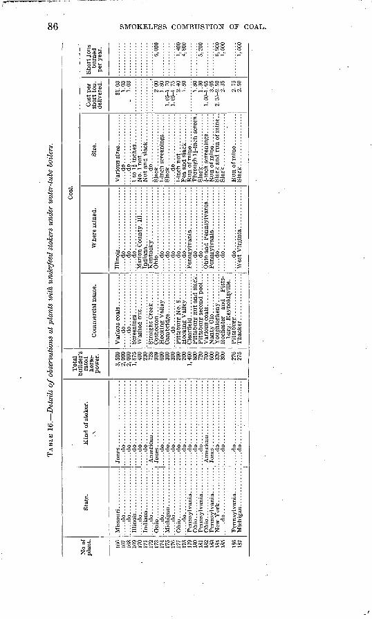
TAB
LE 1
6.
Det
ails
of
obse
rvat
ions
at
plan
ts w
ith
unde
rfee
d st
oker
s un
der
wat
er-t
ube
boile
rs.
00
No
of
plan
t.
166
168
169
170
171
172
174
1 7
^
176
177
178
179
181
182
1 Q
Q
1 fi
d
185
186
187
Sta
te.
.....d
o......
..........
.....d
o......
....
....
..
.....d
o......
....
....
..
.....d
o......
....
....
..
.....d
o......
..........
Oh
io........
....
....
.......d
o......
....
....
..
New
Yor
k.....d
o................
Kin
d of
sto
ker.
.\
....
.do
....
....
....
....
....
....
...d
o..
....
....
....
....
....
.....d
o......................
.....d
o......................
.....d
o......................
....
.do
....
....
....
....
....
.......d
o......................
.....d
o......................
.....d
o.... ...
....
....
....
.. .
.....d
o......................
.....d
o......................
.....d
o......................
.....d
o.... ...
....
....
....
...
.....d
o......................
....
.do
....
....
....
....
....
..
.....d
o......................
....
.d
o..
. ...................
Tot
al
rate
d ho
rse
po
wer
.
3,50
02,
000
2,00
01,
875
400
230
728
909
COO
300
300
200
200
1,40
080
072
070
000
032
030
0
276
275
Co
mm
erci
al n
ame.
.....d
o..................
.....d
o..................
Pit
tsbu
rg N
o. 8
.........
burg
; R
eyno
ldsv
ille
.
Tha
cker
. ...............
Coa
l
Whe
re m
ined
.
Illi
nois
......................
.....d
o......................
.....d
o......................
.....d
o......................
Ohio
........................
.....d
o......................
.....d
o......................
.....d
o......................
.....d
o......................
.....d
o......................
.....d
o......................
.....d
o.... ..................
.....d
o......................
.....d
o......................
Wes
t V
irgin
ia..............
Size
.
....
.do
....
....
....
....
......d
o.................
....
do
....
....
....
....
.S
lack..................
.....d
o.................
Sla
ck..
..."
. ..
....
....
..
Sla
ck..................
Sla
ck..................
Cos
t per
sh
ort
ton,
de
liver
ed.
SI. 0
31.
03.
1.03
2.00
1.80
1. 6
5-1.
70
1. C
5-1.
75
2.40
1.80
1.80
1.30
1. 5
0-1.
65
3.05
2. 3
5-2.
50
2.35
2.75
2.50
Sho
rt io
ns
burn
ed
per
year
.
0,00
0
1,40
04,
800
5,20
0
6,90
01,
500
1,50
0
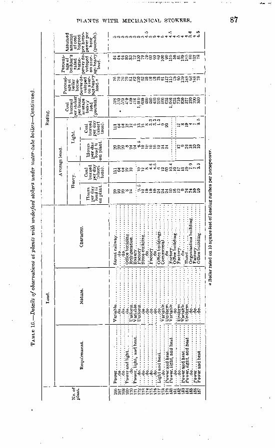
TAB
LE 1
6.
Det
ails
of o
bser
vati
ons
at p
lan
ts u
rith
und
erfe
ed s
toke
rs u
nder
wat
er-t
ube
bo
iler
s C
onti
nued
.
No.
of
plan
t.
166
167
168
169
170
171
172
173
174
175
176
177
178
179
180
181
182
183
184
185
186
187
Loa
d.
Req
uire
men
t.
Pow
er..
...d
o..
....
....
....
....
....
.....d
o......................
....
.do
....
....
....
....
....
....... d
o. .....................
.....d
o......................
.....d
o......................
.....d
o......................
Nat
ure.
....
.do
....
....
....
....
....
....
.do
....
....
....
....
....
.....d
o...................
......do....................
....
.do
....
....
....
....
....
....
.do..
. .................
....
.do
....
....
....
....
....
.....d
o....................
....
.do
....
....
....
....
....
.....d
o...................
.....d
o....................
.....d
o...................
Cha
ract
er.
....
.do
. .....................
.....d
o......................
.....d
o......................
....
.do
....
....
....
....
....
.
....
.do
....
....
....
....
....
.
Ho
tel.
. ....................
Rat
ing.
Ave
rage
load
.
Hea
vy.
Hou
rs
per
day
load
is
on p
lant
.
20
20
20 8 24 9.5
10
10
10
10
24
24
24
10
16
12 9 24
24
10
10
Coa
l bu
rned
pe
r da
y (s
hort
to
ns).
Ill 64
64
22
10 10
12
8 4.5
4.5
6 12
60
10.4
10
17
15
19
7.9
7 3.5
Lig
ht.
Ho
urs
per
day
lo
ad i
s o
n p
lant
.
20
20
20 8 24
24 9.5
10
10
10
10
12
24
24 12 9 24
16
10
10
Coa
l bu
rned
pe
r da
y (s
hort
to
ns).
Ill 64
64
18
12
5 13
15 8 3.3
3.3
1.3
9 20 17 8 19 4 7 3.5
Coa
l bu
rned
>e
r sto
ker
per
hour
, av
erag
e he
avy
load
(p
ound
s).
528
. 53
3 53
3 4c
O 42
0 41
6i.o
to 600
400
450
450
250
500
C25
1,0^
0 62
5 71
0 83
0 52
7 33
0 70
0 35
0
Per
cent
ag
e of
bo
iler
hors
e
pow
er d
e
velo
ped
on a
ver
ag
e he
avy
load
. a 76
76
76
79
SI
S3
130 92
59
£9
£9
78
91
112
115 £8
95
13
9 14
6 68
146 78
Per
cent
ag
e of
bu
ilde
r's
rate
d ho
rse-
so
wer
de
ve
lope
d on
ave
r
age
heav
y lo
ad. 64
64
64
80
.8
3 72
130 79
i9
60
60
63
100 90
115 58
81
139
165 60
127 78
Ass
umed
am
ou
nt
of c
oal
burn
ed
per
hors
e-
jow
ef p
er
hour
(p
ound
s).
5 5 5 5 5 5 5 5 4.5
5 5 4 5 4 4.5
4 5 4 4 ae 4 4.5
o 02
a. B
oile
r ra
ted
on 1
0 sq
uare
fee
t of h
eati
ng s
urfa
ce p
er h
orse
pow
er.
00
-I
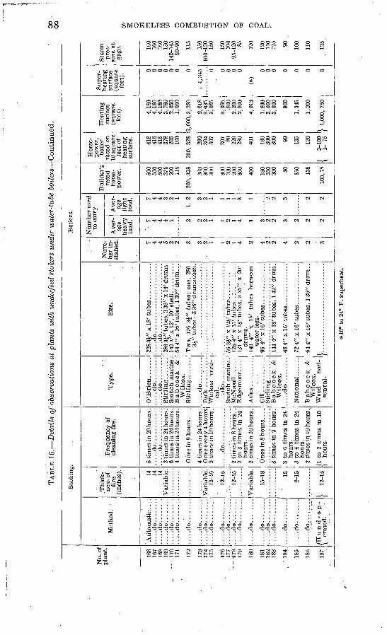
TAB
LE 1
6.
Det
ails
of o
bser
vati
ons
at p
lant
s w
ith
unde
rfee
d st
oker
s un
der
ivat
er-t
ube
bo
iler
s C
onti
nued
.00
00
No.
of
plan
t.
166
167
168
169
- 1
70
171
172
173
174
175
176
177
- -
178
179
ISO
181
182
183
' 184
185
186
187
Sto
kin
g.
Met
hod.
Aut
omat
ic...
. .....d
o....
....
.....d
o....
....
.....d
o....
....
.....d
o....
....
.....d
o....
....
.....d
o........
.....d
o....
....
.....d
o....
....
.....d
o....
....
.....d
o....
....
.....d
o....
....
.... :
do
.-. -
.-:.
. :
.....d
o....
....
.....d
o....
....
.....d
o....
....
.....d
o....
....
.....d
o....
....
.....d
o........
.....d
o........
....
.do
........
/H a
n d
-o
p -
\ er
ated
.
.Thi
ck
ness
of
fire
(i
nche
s). 14
14
14
Var
iabl
e.
Var
iabl
e.
12-1
5
12-1
5
12-1
5
Var
iabl
e.
15-1
8 15
8-15
} 12
-15
Freq
uenc
y of
cl
eani
ng f
ire.
5 tim
es in
20
hour
s.
.....d
o............
.....d
o............
3 tim
es in
24
hour
s .
6 tim
es in
24
hour
s .
4 tim
es in
24 h
ours
.
Onc
e in
9 h
ou
rs....
4 tim
es in
24 h
ours
. O
nce
ever
y 4 h
ours
2
times
in 1
0 ho
urs .
.....d
o............
2 tim
es in
8 h
ours
. .
2 to
3 t
imes
in
24
hour
s.
2 tim
es in
10 h
ours
.
3 tim
es i
n 9
hour
s .
3 to
6 t
imes
in
24
hour
s.
3 to
4 t
imes
in
24
hour
s.
2 tim
es in
10 h
ours
.
fl t
o 2
times
in
10
\ ho
urs.
Boi
lers
.
Typ
e.
....
.do
.........
....
.do
.........
Scot
ch m
arin
e.
Bab
cock
&
W
ilcox
.
.....d
o.........
Par
k ..
...'..
...
Wic
kes
vert
i
cal.
....
.do
.........
Scot
ch m
arin
e .
McN
aull
....
...
Edg
emoo
r....
.
Gil
l..!
........
Bab
cock
&
W
ilcox
. .....d
o.........
Bab
cock
&
W
ilcox
. W
ood
hori
zo
ntal
.
Size
.
.....d
o........................
286
3J"
tube
s, 3
36"
x 1
4' dr
ums
54 4
" x
16' t
ubes
, 1 3
6" d
rum
. . .
Two,
176
34"
tub
es;
one,
280
3J
" tu
bes 3
36"
drum
s ea
ch.
131
4" x
18'
tube
s, 3
35"
x 2
0'
drum
s.
140
4"
x 18
' tu
bes
betw
een
wat
er le
gs.
144
4" x
18'
tube
s, 1
42"
dru
m.
72 4
" x
16' t
ub
es.
..............
64 4
" x
16' t
ubes
, 1
36"
drum
. .
}...............................
Num
be
r in
st
alle
d. 7 4 4 5:
2:
2 3 3 2 1 1 2 1 4 2 4 2 2 4 2 2 3
Num
ber
used
to
car
ry
Ave
r
age
heav
y lo
ad.
' 7 4 4 4 1 2 2 2 1 ! 2 1 4 1 3 2 2 3 2 2 2
Ave
r
age
light
lo
ad. 7 4 4 3 2 1
I, 2 3 2 1 1 1 1 3 1 2 2 3 2 2
Bui
lder
's
rate
d ho
rse
po
wer
.
500
500
500
375
200
115
200,
328 30
3 30
0 30
0
300
100
200
350
400
180
350
300 80
150
138
100,
7.5
Hor
se
pow
er,
boil
er
rate
d o
n 10
squ
are
feet
of
heat
ing
surf
ace. 41
8 41
8 41
8 37
8 20
5 10
0
200,
328 26
2 30
4 30
7
307 80
22
0 28
0
401
180
300
300 90
135
120
f 2-
100
\ 1-
75
Hea
ting
su
rfac
e (s
quar
e fe
et). 4,18
0 4,
180
4,18
0 3,
780
2,05
0 1,
000
2,00
0,3,
280
2,61
8 3,
035
3,06
5
3,06
5 .8
00
2,20
0 2,
800
4,01
3
1,80
0 3,
000
3, 0
00 900
1,34
5
1,20
0
| 1,
000,
750
Super
h
eati
ng
su
rfac
e (s
quar
e fe
et).
0 0 0 0 0 0 0
, 1,
345 0 0 0 0 0
(a)
0 0 0 0 0 0 0
Ste
am
pres
su
re a
t ga
ge. 16
0 16
0 16
0 15
0 14
0-14
5 80
-90
115
150
100-
120
150
150
100
95-1
20
85 120
120
110
125 90
100
110
125
10°
to 2
4° F
. su
per
hea
t.
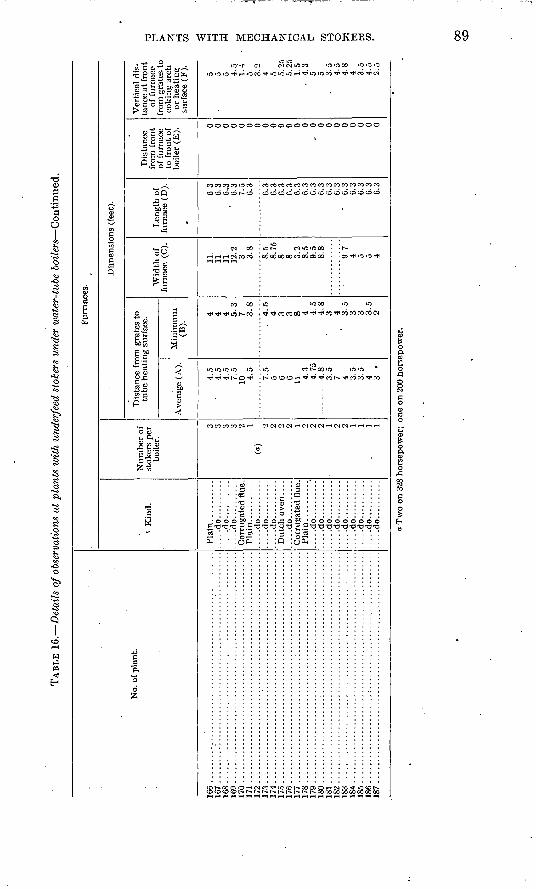
TAB
LE 1
6.
Det
ails
of o
bser
vati
ons
at p
lant
s w
ith
unde
rfee
d st
oker
s un
der
wat
er-t
ube
boil
ers
Con
tinu
ed.
No.
of
pla
nt.
16
6..
....
....
....
....
....
....
....
....
....
....
....
....
....
...
167 .........................................................
168 ..................
....
....
....
....
....
....
....
....
....
...
169..
....
....
....
....
....
....
....
....
....
....
....
....
....
...
170 .........................................................
171 ..................
....
....
....
....
....
....
....
....
....
...
172 ..................
....
....
....
....
....
....
....
....
....
...
173..
....
....
....
....
....
....
....
....
....
....
....
....
....
...
17
4..
....
....
....
....
....
....
....
....
....
....
....
....
....
...
175..
....
....
....
....
....
....
....
....
....
....
....
....
....
...
176 ........................................................
177 ...............................I
.........................
178..
....
....
....
....
....
....
....
....
....
....
....
....
....
...
179..
....
....
....
....
....
....
....
....
....
....
....
....
....
...
180 ..................
...:
....
....
....
....
....
....
....
....
...
181 ..
....
....
....
....
....
....
....
....
....
....
....
....
....
...
182 ..................
....
....
....
....
....
....
....
....
....
...
183..
....
....
....
....
....
....
....
....
....
....
....
....
....
...
184..
....
....
....
....
....
....
....
....
....
....
....
....
....
...
185..
....
....
....
....
....
....
....
....
....
....
....
....
....
...
186......................:..................................
187..
....
....
....
....
....
....
....
....
....
....
....
....
....
...
Fur
nace
s.
t K
ind.
Pla
in..........
.....d
o..........
.....d
o..........
.....d
o..........
Cor
ruga
ted
flue
.
.....d
o..........
.....d
o..........
.....d
o..........
Dut
ch o
ven
....
.....d
o..........
Cor
ruga
ted
flue
. Pl
ain'
. ..
....
...
.....d
o........./
.....d
o..........
.....d
o..........
....
.do
....
....
....
...d
o..
....
....
.....d
o..........
....
.do
....
....
....
...d
o..
....
....
....
.do
....
....
..
Num
ber
of
stok
ers
per
boile
r.
3 3 3 3 2 1 (a
) 2 2 2 2 1 2 2 2 1 2 2 1 1 1 1
Dim
ensi
on
s (f
eet)
.
Dis
tance
fro
m g
rate
s to
tu
be
hea
tin
g s
urfa
ce.
Av
erag
e (A
).
4.5
4.5
4.5
7.5
10
4.5
7.5
5 6 6 11
4.3
4.75
-.
---.
-
4.8
3.5
7 4 3.5
3.5
4 3
Min
imum
(B
).
4 4 4 5.3
7 3
.8
. 4
.5
4 3 3 8 4 4.5
4
.8
3 4 "
3.5
3 3 3.5
2
Wid
th o
f fu
rnac
e (C
).
11.
11
11
12.2
3 3
.8
8.5
8.75
8 8 3.2
8.
5 9.
5 8.
8
9.7
4 5 5 4
Len
gth
of
furn
ace
(D).
6.3
6.3
6.,3
6.
3 7.
5 6.
3
6.3
6.3
6.3
0.3
6.3
6.3
6.3
6.3
6.3
6.3
6.
3 6.3
6.
3 6.
3 6.
3
Dis
tance
fr
om f
ront
of f
urn
ace
to f
ront
of
bo
iler
(E
).
0 0 0 0 0 0 0 0 0 9 9 0 0 ,
0 0 0 0 0 0 0 0 0
Ver
tica
l d
is
tan
ce a
t fr
on
t of
fu
rnac
e fr
om g
rate
s to
co
kin
g a
rch
or h
eati
nt;
su
rfac
e (F
). 5 5 5 4.5
1.4
5 3.2
4 5 5.
25
5.25
1.
5
4.3
5 5 3.5
4.
5 4.8
4 3.5
4.
5 2.5
a T
wo
on 3
28 h
orse
pow
er;
one
on 2
00 h
orse
pow
er.
OO
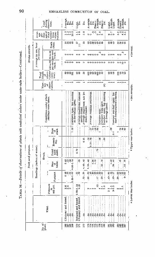
TAB
LE 1
6.
Det
ails
of o
bser
vatio
ns a
t pl
ants
with
und
erfe
ed s
toke
rs u
nder
wat
er-t
ube
boil
ers
Con
tinu
ed.
No.
of
pla
nt.
166
167
168
169
170
171
172
173
174
175
176
177
178
179
180
181
182
183
184
185
186
187
Dra
ft a
nd
pre
ssur
e.
Kin
d.
Chi
mne
y an
d fo
rced
.
.....d
o...............
.....d
o...............
Ind
uce
d a
nd f
orce
d . .
C
him
ney
and
forc
ed .
.....d
o...............
.....d
o...............
.....d
o...............
.....d
o...............
.....d
o...............
.....d
o...............
.....d
o...............
.....d
o....
....
....
...
.....d
o...............
.....d
o...............
.....d
o...............
.....d
o...............
.....d
o...............
.....d
o...............
.....d
o...............
.....d
o...............
Rea
ding
s (i
nch
es o
f w
ater
).
Pre
ssur
e in
as
h pit
.
3.6
2.8
3
0. 9
0-1.
13
2.25
2 1 2 2 .25
4 2.1
2.3
2-3 1.
5 3
-3.2
2 2 3.5
Dra
ft.
Fur
nace
.
0.28
.3
3 34
0. 8
6-l!
02
.35
.32
. 32-
. 35
. 20-
. 30
.48
.20
.23
. 17-
. 25 .32
. 25-
. 55
. 43-
. 66
.4
4 . 1
0-.
17
. 28-
. 50
.1
2
.15
0-.
02
Rea
r of
bo
iler
.
0.48
.5
3 .5
4 a.
98-1
. 16
.39
a. 4
0-. 4
2
&. 3
3-. 4
0
o.28
o.
50
. 55-
. 78
a.60
. 3
4-. 4
4
.19
14-
19
Fro
nt
tube
shee
t.
0.70 .70
Bre
ech
in
g. .50
0. 5
2-. 5
6
.90
.80
Bas
e of
st
ack.
1.50 .57
.70
.64
.88
1
Q9
.9-1
1.2
4.4
0 90
Con
diti
ons
under
whi
ch
read
ings
wer
e ta
ken.
Dam
pers
ope
n, f
an r
un
nin
g
at m
axim
um
spe
ed.
Ave
rage
con
diti
ons;
dam
per
par
tly c
lose
d.
Ave
rage
con
diti
ons;
ash
pit
do
ors
crac
ked.
Ave
rage
runnin
g c
ondi
tion
s.
Dam
per
ope
n;
fan
runnin
g
at a
vera
ge s
peed
.
Dam
per
one
-hal
f op
en;
fur
na
ce d
oors
cra
cked
3 in
ches
.
Sm
oke
reco
rds.
Num
be
r of
ob
ser
va
tion
s. 1 1 1 9 1 2 1 1 1 1 1 1 1 1<*>
1 1 1 1 1 2 1
Tot
al
leng
th
of
obse
r
vati
ons
(min
ut
es). 60
60
60
50
1 60
SO 50 600 60
60
60
60
0 60
40 60
60
90 120 60 58
60
Ave
rage
for
one
hou
r (m
inut
es).
100
to S
O pe
r ce
nt
blac
k. 0 0 0 0 0 0 2 0 0 0 0 0 0 0 0 0 0 0 0 0 10 0
SO to
60
per
cent
blac
k. 0 0 0 0 0 0 0 0 0 0 0 0 .5
0 0 o
2 '
0
0 0 .5
1
Sta
ck
clea
n. 56
56
56
40 57
CO
53 60
60
59
60
60
' 58
48 60
49
60 50
59
55
55
Ave
r
age
per
ce
nt
age
of
blac
k sm
oke
from
ob
ser
va
tion
s.
1.3
1.3
1.3
10.3 1.1
4.8
5.8
0 0 .3
.3
0 1.9
5 0 6.7
0 3.2
.4
4.
3 3.
1
Loa
d duri
ng
obse
rva
ti
ons.
Ave
rage
. D
o.
Do.
D
o.
Lig
ht.
Do.
Do.
Ave
rage
. D
o.
Do.
H
eavy
. A
vera
ge.
Do.
H
eavy
. D
o.
Lig
ht.
Ave
rage
. L
ight
.
Ave
rage
. H
eavy
. A
vera
ge.
Do.
CO o o
W & F
t=J CG en O
O
g w d tn H
o L
ower
rea
r bo
iler
.*
Up
per
rea
r bo
iler
.c
See
rem
arks
.<i
Sev
eral
.
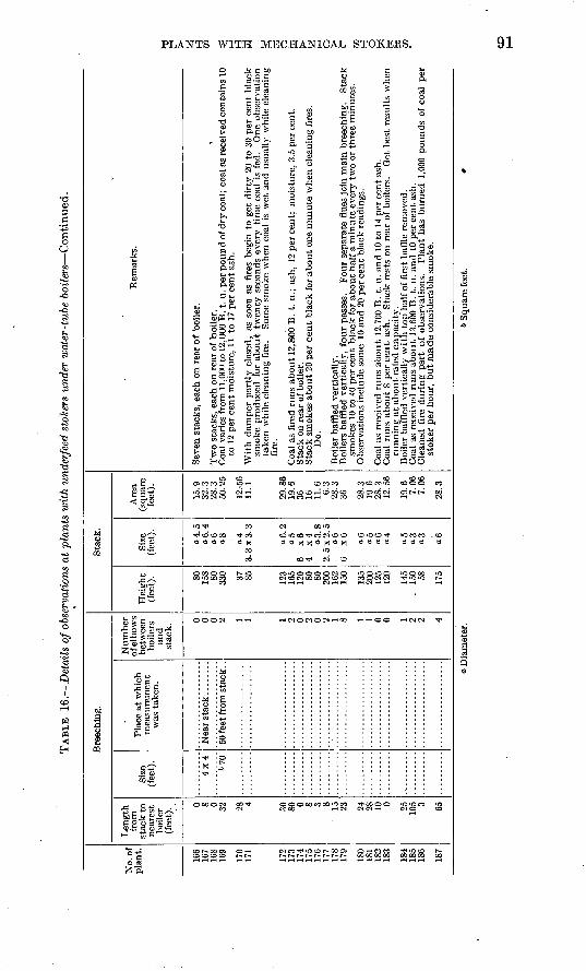
TAB
LE 16.
Det
ails
of o
bser
vati
ons
at p
lan
ts w
ith
unde
rfee
d st
oker
s un
der
luat
er-t
ube
boil
ers
Con
tinu
ed.
No.
of
plan
t.
166
167
168
169
170
171
172
173
174
175
176
177
178
179
ISO
18
1 18
2 18
3
184
185
186
187
Bre
echi
ng.
Len
gth
from
st
ack
to
near
est
boile
r (f
eet)
. t 0 8 0 32 28 4 30
80 0 8 3 8 15
23 24
28
10 0 25
105 3 65
Size
(f
eet)
.
4x4
»70
Plac
e at
whi
ch
mea
sure
men
t w
as t
aken
.
50 fe
et f
rom
sta
ck. .
Num
ber
of e
lbow
s be
twee
n bo
ilers
an
d st
ack.
0 0 0 2 1 1 1 2 0 2 0 2 1 8 1
1 0 0 1 2 2 4
Sta
ck.
Hei
ght
(fee
t). 80
15
8 80
330 37
85 123
165
120 80
80
200
162
150
135
200
125
120
145
. 15
0 58 175
Siz
e (f
eet)
.
a 4.
5
«6.
4 a6
a8 o4
3. 3
x 3
. 3
a 6.
2
«5
.6
x6
4
.x4
aS.S
2.
5 x
2. 5
a6
6
x6 «6
a5
06
04
<*5
«3
«3 a6
Are
a (s
quar
e fe
et).
15.9
32
.3
2S.3
50
.25
12.-5
6 11
.1
29.8
6 19
.6
36
16
11.6
6.3
28
.3
36 28.3
19
.6
28.3
12
.56
19.6
7.
06
7.06
28.3
Rem
arks
.
Seve
n st
acks
, ea
ch o
n re
ar o
f bo
iler.
Tw
o st
acks
, ea
ch o
n re
ar o
f bo
iler
. *
Coa
l va
ries
fro
m 1
1,00
0 to
12,
000
B.
t. u.
per
pou
nd o
f dry
coa
l; co
al a
s re
ceiv
ed c
onta
ins
10
to 1
2 pe
r ce
nt m
oist
ure,
11
to 1
7 pe
r ce
nt a
sh.
Wit
h da
mpe
r pa
rtly
clo
sed,
as
soon
as
fire
s be
gin
to g
et d
irty
20
to 3
0 pe
r ce
nt b
lack
sm
oke
prod
uced
for
abo
ut t
wen
ty s
econ
ds e
very
tim
e co
al "i
s fe
d.
One
obs
erva
tion
ta
ken
whi
le c
lean
ing
fire
. So
me
smok
e w
hen
coal
is
wet
and
usu
ally
whi
le c
lean
ing
fire
.
Coa
l as
fir
ed r
uns
abou
t 12
,800
B. -
t. u.
; as
h, 1
2 pe
r ce
nt;
moi
stur
e, 3
.5 p
er c
ent.
Sta
ck o
n re
ar o
f boi
ler.
S
tack
sm
okes
abo
ut 2
0 pe
r ce
nt
blac
k fo
r ab
out
one
min
ute
whe
n cl
eani
ng f
ires
. D
o.
Boi
ler
baff
led
vert
ical
ly.
Boi
lers
baf
fled
ver
tica
lly,
fou
r pa
sses
. F
our
sepa
rate
flu
es j
oin
mai
n br
eech
ing.
S
tack
sm
okes
10
to 4
0 pe
r ce
nt b
lack
for
abo
ut h
alf
a m
inut
e ev
ery
two
or t
hree
min
utes
. O
bser
vati
ons
incl
ude
som
e 10
and
20
per
cent
bla
ck r
eadi
ngs.
Coa
l as
rec
eive
d ru
ns a
bout
12,
700
B.
t. u.
and
10
to 1
4 pe
r ce
nt a
sh.
Coa
l ru
ns a
bout
S p
er c
ent
ash.
S
tack
res
ts o
n re
ar o
f bo
ilers
. G
et b
est
resu
lts
whe
n ru
nnin
g at
abo
ut r
ated
cap
acit
y.
Boi
ler
baff
led
vert
ical
ly w
ith t
op h
alf
of f
irst
baf
fle
rem
oved
. C
oal
as r
ecei
ved
runs
abo
ut 1
3,60
0 B
. t.
u. a
nd 1
0 pe
r ce
nt a
sh.
Cle
aned
fir
e du
ring
par
t of
obs
erva
tion
s.
Pla
nt h
as b
urne
d 1,
000
poun
ds o
f co
al p
er
stok
er p
er h
our,
bu
t mad
e co
nsid
erab
le s
mok
e.
a D
iam
eter
. 6
Squ
are
feet
. *
CD
92 SMOKELESS COMBUSTION OF COAL.
Plants with return tubular boilers. Underfeed stokers were installed under return tubular boilers at 26 plants. The fires carried ranged in thickness from 12 to 18 inches. Four of the plants burned run- of-mine coal. Seventeen carried a uniform load, and 9 a variable load. The kinds of coal burned were as follows:
Kind of coal burned at plants ivith underfeed stokers under return tubular, boilers.
Number of plants.a
Illinois.......................................................... 1Indiana......................................................... 4Kentucky....................................................... 1Ohio............................................................ 3Pennsylvania.................................................... 8West Virginia.......................................:........... 4Miscellaneous................................"................... 7
Various particulars regarding these plants are condensed in the following statement:
Coal as received burned per stoker per hour, average heavy load, 513 pounds; range, 225 to 750 pounds.
Percentage of rated boiler horsepower developed, average heavy load (boiler rated on 10 square feet of heating surface per horsepower), 74; range, 57 to 135.
Average distance from grates to shell, 2.8 feet; range, 2 to-3.75 feet.Smoke, black, 2.6 per cent.Approximate average pressure in ash pit, 1.75 inches.Approximate average draft in furnace, 0.20 inch; at front tube sheets, 0.30 inch; at
base of stack, 0.50 inch. This gives an average drop of 2 inches between the ash pit and the furnace, 0.10 inch through the boiler, and 0.20 inch from the boiler to the stack.
Details of the observations at plants with underfeed stokers under return tubular boilers are given in Table 17.
a Two plants burned both Ohio and West Virginia coal.
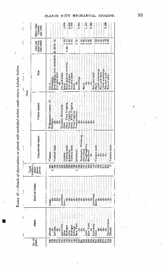
TAB
LE 17.
Det
ails
of o
bser
vati
ons
at p
lant
s w
ith u
nder
feed
sto
kers
und
er r
etur
n tu
bula
r bo
ilers
.
No.
of
pla
nt.
188
189
190
191
192
193
194
195
196
198
199
200
201
202
203
204
205
206
207
208
209
210
211
213
Stat
e.
Illi
nois
................
.....d
o................
.....d
o................
.....d
o................
Oh
io..
....
....
....
....
.....d
o................
.....d
o................
.....d
o................
.....d
o................
.....d
o................
.....d
o................
.....d
o................
.....d
o................
Illin
ois.
...............
Kin
d of
sto
ker.
.....d
o.................
.....d
o.................
.....d
o.................
.....d
o.................
.....d
o.................
.....d
o.................
.....d
o.................
.....d
o.................
.....d
o.................
.....d
o.................
.....d
o.................
.....d
o.................
.....d
o.................
.....d
o.................
.....d
o.................
.....d
o.................
.....d
o.................
.....d
o.................
.....d
o.................
.....d
o.................
.....d
o.................
Tot
albu
ilde
r's
rate
d ho
rse
po
wer
.
200
SC
Aft
?nn
125
530
300
9nn
200
1 V
»
1,10
486
080
073
662
5
260
i zf\
500
500
375
300
o=
n
Com
mer
cial
nam
e.
Wash
ed.................
....
.do
....
....
....
....
..
....
.do..
....
....
....
....
....
.do
....
....
....
....
....
...d
o..
....
....
....
....
....
.do
....
....
....
....
..
Coa
Whe
re m
ined
.
....
.do
....
....
....
....
....
.......d
o......................
.....d
o......................
Ohio
........................
Ohi
o; W
est
Vir
gini
a. .......
.....d
o......................
.....d
o......................
....
.do..
....
....
....
-...
.:..
.-..
.do
....
....
....
....
....
.......d
o......................
.....d
o......................
1.
Size
.
No.
4.......................
.....d
o......................
Sla
ck..
....
....
....
....
....
.
Sla
ck.......................
....
.do
....
....
....
....
....
..
Sla
ck.......................
:....d
o...
......
......
......
......d
o......................
.....d
o......................
Sla
ck..
....
....
....
....
....
.
Cos
t per
sh
ort
ton,
de
liver
ed.
81. 3
0-S1
. 60
1.90
2. 0
0- 2
. 15
2.30
2.05
2.00
2.45
2.00
1.70
2.00
1.95
1.85
1.51
1.51
1.51
1. 7
03.
00
Short
ton
s b
urn
ed
per
year
.
5,03
0
2,60
01,
300
7,00
0
7,50
0
2,88
0
2,00
0
Q CO
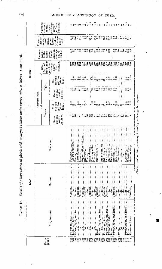
TAB
LE 1
7.
Det
ails
of o
bser
vatio
ns a
t pl
ants
voi
th u
nder
feed
sto
kers
und
er r
etur
n tu
bula
r boil
ers
Con
tinu
ed.
cO
No.
of
plan
t.
188
189
190
191
192
193
194
195
196
197
198
199
200
201
202
203
204
205
206
207
208
209
210
211
212
213
Loa
d.
Req
uire
men
t.
....
.do
....
....
....
....
....
.......d
o......................
....
.do
....
....
....
....
....
....
...d
o..
....
....
....
....
....
.....d
o......................
....
.do
....
....
....
....
....
.......d
o......................
....
.do
....
....
....
....
....
..
Heat.
....
...................
....
.do
....
....
....
....
....
....
...d
o..
....
....
....
....
....
Nat
ure.
.....d
o....................
.....d
o....................
.....d
o....................
Uni
form
. .................
....
.do
....
....
....
....
....
....
.do
....
....
....
....
....
....
.do
....
....
....
....
....
....
.do
....
....
....
....
....
....
.do
....
....
....
....
....
....
.do..
....
....
....
....
....
...d
o..
....
....
....
....
......d
o....................
Cha
ract
er.
Oil
refi
ner y
.................
Sal
t w
orks
..................
Hosp
ital.
....
....
....
....
...
.....d
o......................
.....d
o......................
' R
atin
g.
Ave
rage
load
.
Hea
vy.
Hou
rs
per
day
load
is
on p
lant
. 8 17
10
11
11
18
24
10
12
10
14
24
24
14
24
12
10
12
24
24
24
24
24
12
24
9
Coa
l bu
rned
pe
r da
y (s
hort
to
ns). 4.5
54
15
3.5
. 4 4 15
.4
5 9 3.6
3.5
51
24
13
35
13
.6
11.
7 4 4 22
.3
26
20
19 5.5
14
.5
1.5
Lig
ht.
Ho
urs
per
day
lo
ad i
s on
pla
nt. 8 17
10
11
11
18
24
10 10
14
24
24
14
24
12
10
24
24
24 12 24
9
Coa
l bu
rned
pe
r da
y (s
hort
to
ns).
4 13.5
15
3.5
3.
3 2.8
12
.6
5 2.3
3.5
51
18
4 35
11.4
11
.7
10 2.4
17
.8
'5.5
13.4
1.
25
Coa
l bu
rned
pe
r st
oker
pe
r ho
ur,
aver
age
heav
y lo
ad
(pou
nds)
.
560
582
500
320
728'
22
5 42
7 50
0 75
0 36
0 50
0 70
6 50
0 62
0 73
0 56
5 58
5 33
0 33
5 62
0 54
5 41
6 53
5 46
0 60
0 34
0
Per
cent
ag
e of
bo
iler
hors
e
pow
er
deve
l
oped
on
aver
age
heav
y lo
ad, a
.
135 57
79
70
88
70
50
58
100 58
104 69
55
66
70
70
10
2
.63 76
80
61
80
65
10
4 68
Per
cent
ag
e of
bu
ilde
r's
rate
d ' h
orse
po
wer
de
vel
op
ed o
n av
erag
e he
avy
load
. 112 73
10
0 77
116 89
68
74
167 72
148 96
58
79
100
100
117 92
89
88
87
67
87
68
12
1 91
Ass
umed
am
ount
of
coa
l, bu
rned
pe
r hor
se
pow
er
per
hour
(p
ound
s).
5 5 5 5 5 5 5 4.5
4.5
5 4.5
4 4 4 4 4.5
4 4 5 5 5 .
5 5 4.5
4 5
^Boi
ler
rate
d o
n 10
squ
are
feet
of h
eati
ng s
urfa
ce p
er h
orse
pow
er.
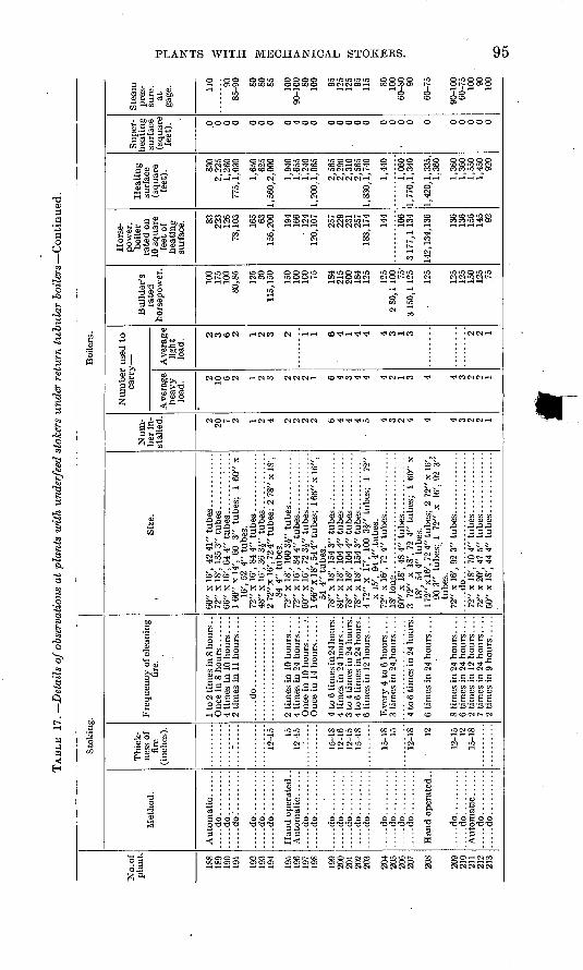
TAB
LE 17.
Det
ails
of o
bser
vati
ons
at p
lant
s w
ith
unde
rfee
d st
oker
s un
der
retu
rn t
ubula
r boil
ers
Con
tinu
ed.
INo.
of
pla
nt.
188
189
190
191
192
193
194
195
196
197
198
199
200
201
202
203
204
205
206
207
208
209
210
211
212
213
Sto
king
.
Met
hod.
.....d
o........
....
...d
o..
....
....
.....d
o..........
.....d
o..........
.....d
o..........
.....d
o..........
Han
d o
per
ated
..
.....d
o..........
.....d
o..........
.....d
o..........
.....d
o..........
.....d
o..........
.....d
o..........
.....d
o..........
.....d
o..........
.....d
o..........
.....d
o..........
.....d
o..........
Han
d op
erat
ed..
.....d
o..........
.....d
o..........
.....d
o..........
.....d
o..........
Thi
ck
ness
of
fire
(i
nche
s).
- 12-1
5 15
12-1
5
15-1
8 12
-16
12-1
5 15
-18
15-1
8 15
i2-is 12
12-1
5 12
15-1
8
Fre
quen
cy o
f cle
anin
g fi
re.
1 to
2 ti
mes
in 8
hou
rs .
.
4 ti
mes
in
10 h
ours
. . .
. 2
tim
es i
n 11
hou
rs.
. ..
.....d
o................
4 ti
mes
in
24 h
ours
...
.
Onc
e in
14
hour
s ......
4 to
6 t
imes
in 2
4 ho
urs.
4
tim
es i
n 24
hours
. . .
. 3
to 4
tim
es in
24
hour
s.
4 to
6 ti
mes
in 2
4 ho
urs.
6
tim
es i
n 12
hours
. . .
.
Ever
y 4
to
6 hours
. . .
. 3
tim
es i
n 24
^hou
rs ...
.
4 to
6 t
imes
in 2
4 ho
urs.
6 ti
mes
in
24 h
ours
...
.
S ti
mes
in
24 h
ours
....
2 ti
mes
in
12 h
ours
...
.
2 ti
mes
in
9 ho
urs .....
Boi
lers
.
Siz
e.
60"
x 16
', 42
41"
tu
bes
.......
72"
x 18
', 13
5 3"
tu
bes
. ..
....
....
.66
" x 1
6',
64 4
" tu
bes
.. .......:.
...
1 60
" x
14',
60
3" t
ubes
; 1
60"
x 16
', 52
4"
tube
s.
72"
x 16
', 84
4"
tub
es .............
48"
x 16
', 36
3J"
tu
bes
. . .
....
....
.2
72"
x 16
', 72
4" t
ub
es;
2 78
" x
18',
84 4
" tu
bes.
72
" x
18',
100
3J"
tubes
. ..
....
....
72"
x 16
', 84
4"
tubes..............
60"
x 16
', 72
3i"
tubes
.. . ..
....
....
1 66
" x 1
8', 5
44"
tub
es;
1 66
" x
16",
54
4"
tube
s.
78"
x 18
', 15
4 3"
tubes
.. :..........
84"
x 18
', 10
44"
tubes............
78"
x IS
', 10
4 4"
tubes
.. . ..........
78"
x 18
', 15
4 3"
tubes
.. . ..........
4 72
" x
17',
100
3£"
tube
s;
1 72
" x
15',
94 4
" .tu
bes.
72
" x 1
6',
724"
tu
bes..
....
....
....
3 72
" x 1
8',
72 4
" tu
bes;
1
tiO"
x 18
', 54
4"
tube
s.
1 72
" x 1
6', 7
2 4"
tub
es;
2 72
" x
16',
90 3
" tu
bes;
1
72"
x 16
', 92
3"
tube
s.
72"
x 16
', 92
3"
tubes
.. ...
....
....
......d
o............................
72"
x 20
', 47
5"
tub
es. ............
60"
x IS
', 44
4"
tub
es. ............
Num
be
r in
st
alle
d. 2 20 7 2 1 2 4 2 2 2 2 b 4 4 4 5 4 3 2 4 4 4 3 2 2 1
Num
ber
use
d to
ca
rry
Ave
rage
h
eav
y
load
. 2 10 6 2 1 2 3 2 2 2 1 6 4 3 4 4 4 2 1 3 4 4 3 2 o 1
Ave
rage
li
ght
load
. 2 3 6 2 1 2 3 2 1 1 6 4 1 4 4 4 3 1 3 2 2 1
Buil
der
's
rate
d
hors
epow
er.
100
175
100
80,8
5
125 30
115,
150
150
100
100 75 184
215
200
184
125
125
2 80
, 1 1
00
75'
3150
,112
5
125
125
125
150
125
.75
Hor
se
pow
er,
boil
er
rate
d o
n 10
squ
are
feet
of
heat
ing
surf
ace. S3
22
3 12
6 78
, 103 16
5 63
156,
200
194
166
' 12
4 12
0, 1
07 257
229
231
257
183,
174 14
4
106
3177
,113
4
142,
134,
136
136
136
156
145 92
Hea
tin
g
surf
ace
(squ
are
feet
). 830
2,22
5 1,
260
775,
1,03
0
1,65
0 62
5 1,
560,
2,00
0
1,94
0 1,
655
Ii24
0 1,
200,
1,06
5
2,56
5 2,
290
. 2,3
10
2,56
5 1,
830,
1,74
0
1,44
0
1,06
0 1,
770,
1,34
0
1,42
0,1,
335,
1,
360
1,36
0 1,
360
1,55
0 1,
450
920
Sup
er
heat
ing
surf
ace
(squ
are
feet
). 0 0 0 0 0 0 0 0 4 0 0 0 0 0 0 0 0 0 0 0 0 0 0 0 0 0
Ste
am
pres
su
re,
at
gage
. 110 90
85
-90 80
80
85 10
0 90
-100
80
10
0 95
125
125 95
115 80
100
60-8
0 90
60-7
5
90-1
00
60-7
5 10
0 90
100
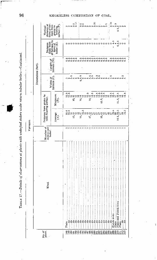
TAB
LE 1
7.
Det
ails
of o
bser
vati
ons
at p
lant
s w
ith
unde
rfee
d st
oker
s un
der
retu
rn t
ubul
ar b
oil
ers
Con
tinu
ed.
CD
No.
of
plan
t.
188
189
190
191
192
193
194
195
196
197
198
'199
20
0 20
1 20
2 20
3 20
4 20
5 20
6 20
7 20
8 20
9 21
0 21
1 21
2 21
3
Fur
nace
s.
Kin
d.
Pla
in ...
....
....
....
....
....
. ..
.."..
....
....
....
....
....
....
....
....
....
.. .d
o ................................................................
....
.do
................................................................
....
.do
................................................................
....
.do
....
....
....
....
....
....
....
....
....
....
....
....
....
....
....
....
...
....
.do
....
....
....
....
....
....
....
....
....
....
....
....
....
....
....
....
.......d
o........
....
....
....
....
....
....
....
....
....
:...
....
....
....
....
...
.. .d
o .................................................................
.....d
o..................................................................
.....d
o..................................................
....
....
....
...
....
.do
....
....
....
....
....
....
....
....
....
....
....
....
....
....
....
....
......d
o........
..........................................
....
....
....
...
....
.do
....
....
....
....
....
....
....
....
....
....
....
....
....
....
....
....
.....d
o........
..........................................
....
....
....
...
....
.do
....
....
....
....
....
....
....
....
....
....
....
....
....
....
....
....
.......d
o........
..........................................
....
....
....
...
.....d
o..............................................................;.
......d
o........
..........................................
....
....
....
...
....
.do
....
....
....
....
....
....
....
....
....
....
....
....
....
....
....
....
......d
o....................................'.............................
Pla
in .................................................. ̂
...............
Pla
in .........
..........................................
...............
....
.do
....
....
....
....
....
....
....
....
....
....
....
....
....
....
....
....
...
.. .d
o ..
....
....
....
....
....
....
....
....
....
....
....
....
....
....
....
...
Num
ber
of
stok
ers
per
boile
r.
1 1 1 1 1 1 1 1 1 1 1 1 1 1 1 1 1 1 1 1 1 1 1 1 1 1
Dim
ensi
ons
(fee
t).
Dis
tanc
e fr
om g
rate
s to
tu
be h
eati
ng s
urfa
ce.
Ave
rage
(A
).
15.5
15
.5
15
13,1
5 15
16
15, 1
7 .
16.5
15
15
17
,15 17
17
17
17
16
,13 15
17
18
17
19
.5
20
14. 5
, 19.
5
17
19
16.5
Min
imu
m
(B).
12.5
12
.5
12
10,1
2 12
13
12,1
4 14
12
12.5
14
,12 14
.5
14
14.5
14
.5
13. 5
, 12.
5
12.5
14
15
14
.5
16.5
17
11
.5,1
6.5
14
16
14.5
Wid
th o
f fu
rnac
e (C
).
5 6 5.5
5 6 4
6,6
.5
6 6 5 5.5
6.
5 7 6.3
6.
5 6 6 6 5 7.
5 6 6 6 6 6.
2 5
Len
gth
of
furn
ace
(D).
6.3
6.3
6.3
6.3
6.3
6 6.3
6.3
6.3
6.3
6.3
6.3
6.3
6.3
6.3
6.3
6.3
6.3
6 6.3
6.3
6.3
6.3
6.3
6.3
6.3
Dis
tanc
e fr
om f
ront
of
fur
nace
to
fr
ont o
f bo
iler
(E). 0 0 0 0 0 0 0 0 0 0 0 0 0 0 0 0
0 0 0 0
4.
5 4
0,4.
5 0 0 0
Ver
tical
di
stan
ce a
t fr
ont
of f
ur
nace
fro
m
grat
es t
o he
atin
g su
rfac
e (F
). 3 3 3 2.5
2.75
2.5
2.5
3 3 3 3 3.25
3 3
. 3 3 2.
5
3.75
2 2.
3 2.
5,2 3 3 3
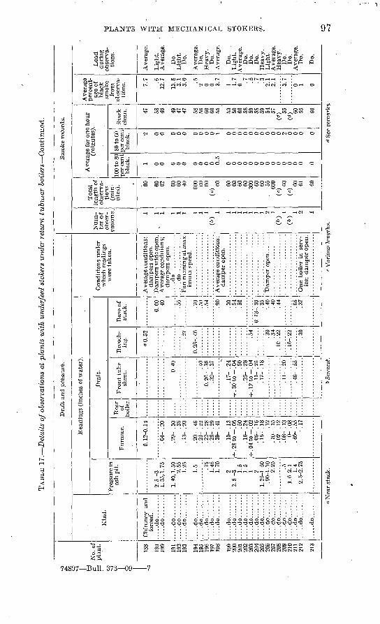
TAB
LE 1
7.
Det
ails
of o
bser
vati
ons
at p
lant
s iv
ith
unde
rfee
d st
oker
s un
der
retu
rn t
ubm
ar
bo
iler
s C
onti
nued
.
No.
of
pla
nt.
188
189
190
191
192
193
194
195
196
197
198
199
200
201
' 20
2 20
3 20
4 20
5 20
6 20
7 20
8 20
9 21
0 21
1 21
2
213
Dra
ft a
nd p
ress
ure.
Kin
d.
Chi
mne
y an
d fo
rced
. ..
...d
o..
....
.......d
o........
.....d
o........
.....d
o........
.....d
o.........
....
.do
....
.....
....
.do
....
....
.....d
o........
.....d
o........
.....d
o.........
.....d
o.........
....
.do
....
....
.....d
o........
.....d
o.........
.....d
o.........
.....d
o.........
.....d
o........
.....d
o.........
.....d
o.........
....
.do
....
....
.....d
o.........
....
.do
....
....
....
.do
....
.....
.....d
o......
..:
Rea
ding
s (i
nche
s of
wat
er).
Pre
ssur
e in
as
h pi
t.
2.5
-3
1. 4
0, 1
. 50
2.55
1.
25
1.5 .75
1.45
1.
70
2 2.
5 -3
1.5
1.5
1 2 1.
25-
1. 5
0 .9
0-1.
10
2.25 .5
1.
6-2.
1 1.
4 2.
5-2
. 75
Dra
ft.
Fur
nace
.
0.12
-0.1
4
.04-
.20
.29-
.30 .3
6 . 1
3- .
20
. 20-
. 4
6 .2
1- .
22.2
2- .
28
.28-
.29
. 3
9- .
41
.10-
.13
+
.28
to -
.06
.5
0 . 1
6- .
24
+ .0
4 to
-.0
2
.06-
.16
. 1
5- .
IS
.12
. 10-
. 1
5 .0
2- .
12.0
8- .
13
0- .
08
.46-
.55
-.
17
Rea
r of
bo
iler.
Fro
nt
tub
e sh
eet. 0.
40 .40
0. 2
C-
. 36
.32-
.37
.17-
.24
+ .3
0-t
o-.
04
.50
.25-
.28
+ .1
2 to
-.0
4
.17-
.18
.11-
.20
.46-
.55
Bre
ech
in
g.
aO.5
2
.27
0. 2
S-. <
6
.54
.30
.34
. 1C-
. 22
.16-
. 22
.30
1
Bas
e of
st
ack. 0.60
.4
0
.70 50
Con
diti
ons
unde
r w
hich
rea
ding
s w
ere
take
n.
Ave
rage
con
diti
ons;
da
mpe
rs o
pen.
D
ampe
rs w
ide
open
. A
vera
ge c
ondi
tion
s;
dam
pers
ope
n.
....
.do
....
....
....
..F
an r
unnin
g a
t max
im
um s
peed
.
54 .90
.30
.50
.35
.40
.40
.44
.65
.37
Ave
rage
con
diti
ons;
da
mpe
r op
en.
I:::::
::::::
::::::
:::
One
boi
ler
in s
erv
ic
e; d
ampe
r op
en.
Sm
oke
reco
rds.
Num
be
r o
f ob
ser
v
atio
ns. 1 1 1 1 1 1 1 1 1
(")
1 1 1 1 l 1 1 2 1(«
0 (&) 2 1
Tot
al
leng
th o
f ob
serv
a
tion
s (m
in
utes
). 60 60
62 60
60
40 600 60
60
(<
0 60 60
60
60
60
30
0 60
60
. 55
60
0 (c
) 60
(c
) 60
61 60
Ave
rage
for
one
hou
r (m
inut
es).
100
to S
O pe
r ce
nt
blac
k. 1 0 0 6 0 0 0 0 0 0 0.5
0 0 0 0 0 0 0 0 0 0 0 0 0 0 0
80 to
60
per
cent
bl
ack. 2 0 0 0 0 0 0 0 0 0 1 0 0 0 0 0 0 0 0 0 0 2 0 0 0 0
Sta
ck
clea
n. 47 58
46 49
47
47 58
56
60
60
55 53
50
60
58
59
58
59
54
57
(<*) 55
<<*) 60
55 60
Ave
rage
pe
rcen
t
age
of
blac
k sm
oke
from
ob
serv
a
tion
s. 7.7 .6
12.7
13.8
3.
1 3.
0 .5
2 0 0 3.7
1 1.7
0 . 7
.5
. 7
.3
2.1
2.1
3.7
0 1 0
Loa
d du
ring
ob
serv
a
tion
s.
Ave
rage
.
Lig
ht.
Ave
rage
.
Do.
L
ight
. D
o.
Ave
rage
. D
o.
Hea
vy.
Do.
A
vera
ge.
Do.
L
ight
. A
vera
ge.
Do.
D
o.
Do.
H
eavy
. L
ight
. A
vera
ge.
Hea
vy.
Do.
D
o.
Ave
rage
. D
o.
Do.
.0
Nea
r st
ack.
>> S
ever
al.
r V
ario
us l
engt
hs.
d Se
e re
mar
ks.
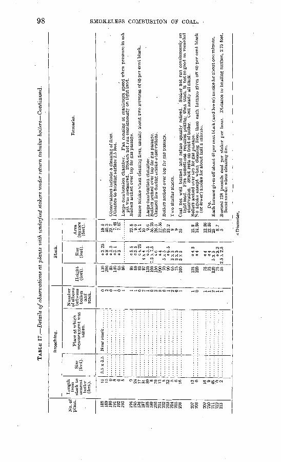
TAB
LE 1
7.
Det
ails
of
obse
rvat
ions
at
plan
ts w
ith
imde
rfee
d st
oker
s un
der
retu
rn t
ubul
ar b
oil
ers
Con
tinu
ed.
CD
C
O
No.
of
pla
nt
188
189
190
191
192
193
194
195
196
197
198
199
200
201
202
203
204
205
206
207
208
209
210
211
212
213
Bre
echi
ng.
Len
gth
from
st
ack
to
near
est
boil
er
(fee
t). 15
15
0 8 0 5 9 24
17
31
30 6 70
13 5 32 5 6 16 13 0 16 9 45
'0 2
Size
(f
eet)
.
3.5
x 3.
5
Pla
ce a
t w
hich
m
easu
rem
ent
was
ta
ken
.
Nu
mb
er
of e
lbow
s be
twee
n bo
ilers
an
d st
ack.
0 2 0 1 0 1 1 1 0 2 1 0 3 0 0 1 2 0 1 1 0 1 1 2 1 1
Sta
ck.
Hei
ght
(fee
t). 110
200 85
140 65
80 95
SO
80
97
130
100
150
200 70
90
65
75
100
125
100 75 75
120 75
55
Size
(f
eet)
.
a3.2
5 a8
a5
.5
a3.1
a3 .0
5.5
a 3.
5
a 4.
25
4x4
a3.5
7.
5 x
7.5
06
a4
5x
5
a6.5
3
x3
3
x3
5
x5 a 4.
5
a4 a4
04
5x
5
a 3.
3
2.5
x 2.
5
Are
a (s
quar
e (f
eet)
.
10.5
50
.3
23.7
7.
45
7.07
23.8
9.
6 14
.1
16 9.6
56.2
5 28
.3
12.5
6 25
33
.2
9 9 25 15.9
12
.56
12.5
6 12
.56
25 8.7
5
Rem
arks
.
Obs
erva
tion
s in
clud
e a
clea
ning
of f
ires
. D
ista
nce
to h
eati
ng s
urfa
ce 2
.5 f
eet.
Lar
ge c
ombu
stio
n ch
ambe
r.
Fan
run
ning
at
max
imu
m s
peed
whe
n pr
essu
re i
n as
h pit
was
mea
sure
d.
Sto
kers
not
run
con
tinu
ousl
y on
lig
ht
load
. B
oile
rs a
rche
d ov
er t
op f
or g
as p
assa
ge.
Som
e sm
oke
whe
n cl
eani
ng f
ires
, us
uall
y ab
out
two
min
ute
s of
60
per
cen
t bl
ack.
Lar
ge c
ombu
stio
n ch
ambe
r.
Boi
lers
arc
hed
over
top
for
gas
pas
sage
. C
lean
ed f
ire
duri
ng s
mok
e ob
serv
atio
ns.
Boi
lers
arc
hed
over
top
for
gas
pas
sage
.
Tw
o si
mil
ar s
tack
s.
Coa
l not
wel
l burn
ed
and
re
fuse
us
uall
y re
tire
d.
Sto
ker
no
t ru
n c
onti
nuou
sly
on
ligh
t lo
ad.
Fir
e so
met
imes
req
uire
s po
'kin
g; th
en s
tack
is
not
so g
ood
as r
ecor
ded
obse
rvat
ion.
S
tack
res
ts o
n fr
ont
of b
oile
r.
Coa
l ne
arly
all
sla
ck.
Boi
lers
arc
hed
over
top
for
gas
pas
sage
. N
o sm
oke
exce
pt w
hen
clea
ning
fir
es;
then
eac
h fu
rnac
e gi
ves
off
60 p
er c
ent
bla
ck
(or
low
er)
smok
e fo
r ab
out
hal
f a
min
ute
.
Do.
E
ach
furn
ace
give
s of
f ab
out
40 p
er c
ent
blac
k (a
nd l
ower
) sm
oke
for
about
one
min
ute
.
Bur
ned
728
pounds
coal
per
sto
ker
per
hou
r.
Dis
tanc
e to
hea
ting
sur
face
, 2.
75 f
eet.
S
ome
smok
e w
hen
clea
ning
fir
e.
o
o g
w
d
in H
oDia
met
er.
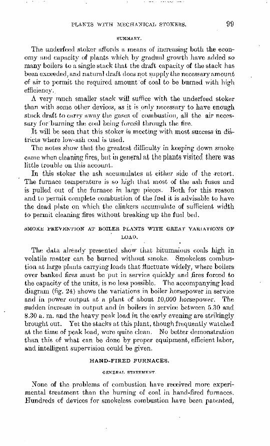
PLANTS WITH MECHANICAL STOKERS. 99
SUMMARY.
The underfeed stoker affords a means of increasing both the econ omy and capacity of plants which by gradual growth have added so many boilers to a single stack that the draft capacity of the stack has been exceeded, and natural draft does not supply the necessary amount of air to permit the required amount of coal to be burned with high efficiency.
A very much smaller stack will suffice with the underfeed stoker than with some other devices, as it is only necessary to have enough stack draft to carry away the gases of combustion, all the air neces sary for burning the coal being forced through the foe.
It will be seen that this stoker is meeting with most success in dis tricts where low-ash coal is used.
The notes show that the greatest difficulty in keeping down smoke came when cleaning fires, but in general at the plants visited there waslittle trouble on this account.
In this stoker the ash accumulates at either side of the -retort. The furnace temperature is so high that most of the ash fuses and is pulled out of the furnace in large pieces. Both for this reason and to permit complete combustion of the fuel it is advisable to have the dead plate on which the clinkers accumulate of sufficient width to permit cleam'ng foes without breaking up the fuel bed.
SMOKE PREVENTION AT BOILER PLANTS WITH GREAT VARIATIONS OF
LOAD.
The data already presented show that bitumnious coals high in volatile matter can be burned without smoke. Smokeless combus tion at large plants carrying loads that fluctuate widely, where boilers over banked fires must be put in service quickly and foes forced to the capacity of the units, is no less possible. The accompanying load diagram (fig. 24) shows the variations in boiler horsepower in service and in power output at a plant of about 10,000 horsepower. The sudden increase in output and in boilers in service between 5.30 and 8.30 a. m. and the heavy peak load in the'early evening are strikingly brought out. Yet the stacks at this plant, though frequently watched at the time of peak load, were quite clean. No better demonstration than this of what can be done by proper equipment, efficient labor, and intelligent supervision could be given.
HAND-FIRED FURNACES.
GENERAL STATEMENT.
None of the problems of combustion have received more experi mental treatment than the burning of coal in hand-foed furnaces. Hundreds of devices for smokeless combustion have been patented,
100 SMOKELESS COMBUSTION OF COAL.
but almost without exception they have proved failures. This record may be explained by the fact that many of the patentees have been unfamiliar with all the difficulties to be overcome, or have begun at the wrong end. Numerous patents cover such processes as causing the waste gases to reenter the furnace, and schemes for collecting and burning the soot are legion. So many -manufacturers who have been looking for some cheap addition to a poorly constructed furnace
Total kilowatt output
Rated boiler horsepower in service
5A..M. . 0 3RM. 8 12
FIGURE 24. Load and boiler-service chart of large power plant with mechanical stokers. The total rated boiler horsepower used to supply the demand for power varied from about 2,000 to 12,000. This plant is absolutely smokeless.
to make it smokeless have experienced inevitable failure that the work of educating the public to rid cities of the smoke nuisance has been hard, long, and only partly successful.
The total number of steam plants having boilers fired by hand is far greater than the total of plants with mechanical stokers, but if the comparison is based on total horsepower developed the figures show less difference. Particularly is this true in sections of the Middle West, where mechanical stokers are generally used at large plants.
HAND-FIKED FURNACES. ' 101
As a general rule hand-fired plants do not have proper furnaces, and methods of operation are far from conducive to good combustion. Coal is usually,fired in large quantities, and little opportunity is given for the air and gases to mix before the heating surface is reached and combustion is arrested. In all the hand-fired plants visited success in smoke prevention has been obtained chiefly by careful firing. The coal was thrown on often in small quantities; the fire was kept clean, enough ash to prevent the passage of air through the fire never being allowed to collect on the grate; and more air was supplied at firing than after the volatile matter had been distilled. Even with such precautions the plants might have made objectionable smoke at times but for the fact that usually some method was employed -for mixing the gases and air before they reached the heating surface.
COKING FURNACE.
One pattern of furnace that requires less attention from the fireman and less care in operating than the usual hand-fired types was found at several plants. This is known as the coking furnace, which in its earliest form was the invention of James Watt. With this furnace large charges of coal may be fired at one time. The coal is shoveled or fed from magazines to a dead plate at the mouth of the furnace, where the volatile compounds distill, and the coal is later pushed back. Unfortunately, in the model of this furnace generally used the magazines are open after the coal on the dead plate has burned down, so that the coal is consumed with a large excess of air.
STEAM JETS.
A clean stack with hand firing is not as good evidence of efficient operation as it is with almost any type of mechanical stoker, because of the special devices used with hand-fired boilers to prevent smoke. Steam jets are the most common of such devices. Usually they are not automatic, and at many plants they are allowed to run longer than is necessary or else are not used at all. Any steam jet that will so mix the gases and air at the times of greatest need, when coal is fired, as to prevent smoke will, if allowed to run continuously, probably waste more of the energy in the coal than it will save. At the same time a steam and air admission device allows a regulation which, if properly made, will keep a stack clean and save coal.
The steam jet is found in an improperly designed furnace or in one where the air supply is too small. It is an expensive device, all conditions being considered. The only purpose it can serve is to mix the air and gases.intimately and prevent the combustible gases from coming too quickly into contact with the heating surface. The claims sometimes made that the use of a steam jet will increase the thermal value of the fuel are erroneous.
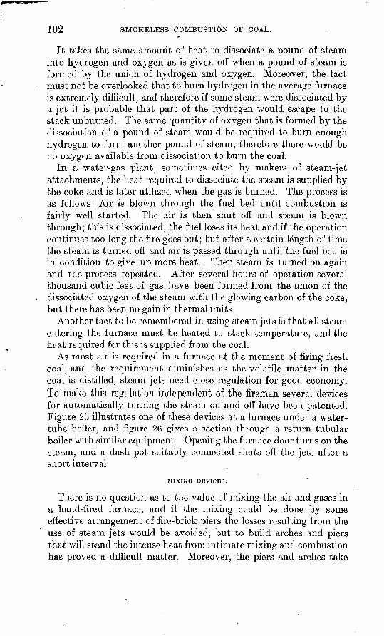
102 SMOKELESS COMBUSTION OF COAL.
It takes the same amount of heat to dissociate a pound of steam into hydrogen and oxygen as is given off when a pound of steam is formed by the union of hydrogen and oxygen. Moreover, the fact must not be overlooked that to burn hydrogen in the average furnace is extremely difficult, and therefore if some steam were dissociated by a jet it is probable that part of the hydrogen would escape to the stack unburned. The same quantity of oxygen that is formed by the dissociation of a pound of steam would be required to burn enough hydrogen to form another pound of steam, therefore there would be no oxygen available from dissociation to burn the coal.
In a water-gas plant, sometimes cited by makers of steam-jet attachments, the heat required to dissociate the steam is supplied by the coke and is later utilized when the gas is burned. The process is as follows: Air is blown through the fuel bed until combustion is fairly well started. The air is then shut off and steam is blown through; this is dissociated, the fuel loses its heat and if the operation continues too long the fire goes out; but after a certain length of time the steam is turned off and air is passed through until the fuel bed is in condition to give up more heat. Then steam is turned on again and the process repeated. After several hours of operation several thousand cubic feet of gas have been formed from the union of the dissociated oxygen of the steam with the glowing carbon of the coke, but there has been no gain in thermal units.
Another fact to be remembered in using steam jets is that all steam entering the furnace must be heated to stack temperature, and the heat required for this is supplied from the coal.
As most air is required in a furnace at the moment of firing fresh coal, and the requirement diminishes as the volatile matter in the coal is distilled, steam jets need close regulation for good economy.To make this regulation independent of the fireman several devices for automatically turning the steam on and off have been patented. Figure 25 illustrates one of these devices at a furnace under a water- tube boiler, and figure 26 gives a section through a return tubular boiler with similar equipment. Opening the furnace door turns on the steam, and a dash pot suitably connected shuts off the jets after a short interval.
MIXING DEVICES.
There is no question as to the value of mixing the air and gases in a hand-fired furnace, and if the mixing could be done by some effective arrangement of fire-brick piers the losses resulting from the use of steam jets would be avoided, but to build arches and piers that will stand the intense heat from intimate mixing and combustion has proved a difficult matter. Moreover, the piers and arches take
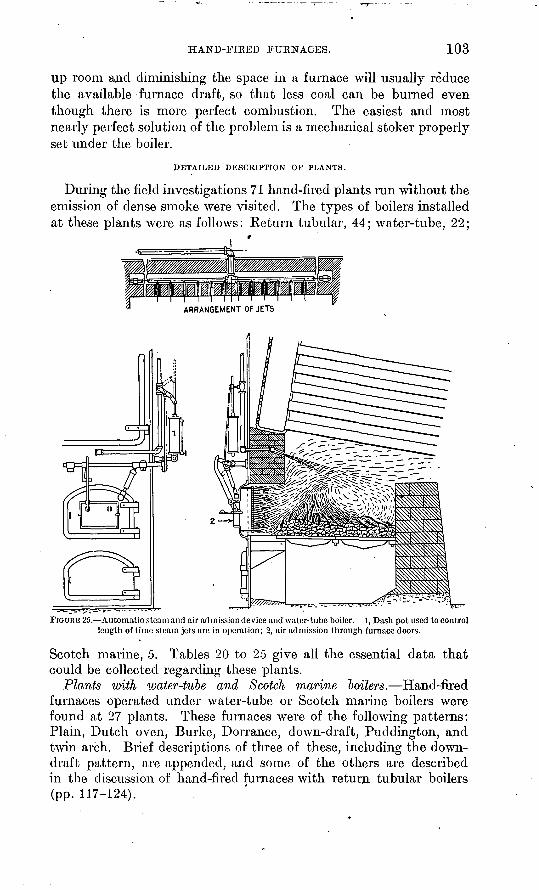
HAND-FIBED FURNACES. 103
up room and diminishing the space in a furnace will usually reduce the available furnace draft, so that less coal can be burned even though there is more perfect combustion. The easiest and most nearly perfect solution of the problem is a mechanical stoker properly set under the boiler.
DETAILED DESCRIPTION OF PLANTS.
During the field investigations 71 hand-fired plants run without the emission of dense smoke were visited. The types of boilers installed at these plants were as follows: Return tubular, 44; water-tube, 22;
FIGURE 25. Automatic stearn and air admission device and water-tube boiler, l, Dash pot used to control length of time steam jets are in operation; 2, air admission through furnace doors.
Scotch marine, 5. Tables 20 to 25 give all the essential data that could be collected regarding these plants.
Plants witli water-tube and Scotch marine toilers. Hand-fired furnaces operated under water-tube or Scotch marine boilers were found at 27 plants. These furnaces were of the following patterns: Plain, Dutch oven, Burke, Dorrance, down-draft, Puddington, and twin arch. Brief descriptions of three of these, including the down- draft pattern, are appended, and some of the others are described in the discussion of hand-fired furnaces with return tubular boilers (pp. 117-124).
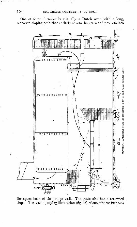
104 SMOKELESS COMBUSTION OF COAL.
One of these furnaces is virtually a Dutch oven with a long, rearward-sloping arch that entirely covers the grate and projects into
the space back of the bridge wall. The grate also has a rearward slope. The accompanying illustration (fig. 27) of one of these furnaces
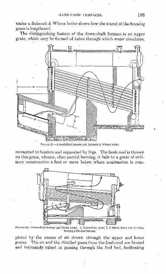
HAND-FIRED FURNACES. 105
under a Babcock & Wilcox boiler shows how the travel of the burning gases is lengthened.
The distinguishing feature of the down-draft furnace is an upper grate, which may be formed of tubes through which water circulates,
FIGURE 27. A hand-fired furnace and Babcock & Wilcox boiler.
connected to headers and supported by lugs. The fresh coal is thrown on this grate, whence, after partial burning, it falls to a grate of ordi nary construction a foot or more below, where combustion is com-
FIGURE 28. Down-draft furnace and Heine boiler. 1, Water-tube grate; 2, C tile on lower row of tubes,forming a'.tile-roof furnace.
pleted by the excess of air drawn through the upper and lower grates. The air and the distilled gases from the fresh coal are heated and intimately mixed in passing through the fuel bed, facilitating
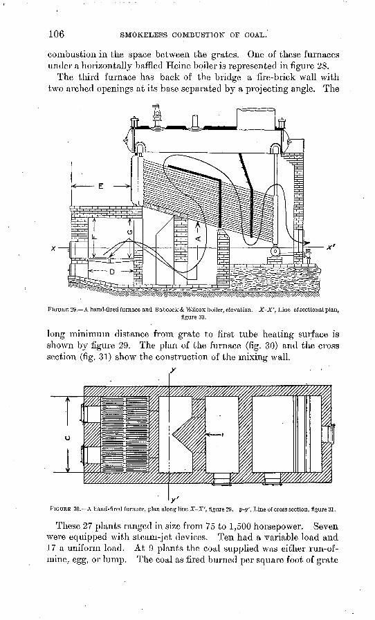
106 SMOKELESS COMBUSTION OF COAL.
combustion in the space between the grates. One of these furnaces under a horizontally baffled Heine boiler is represented in figure 28.
The third furnace has back of the bridge a fire-brick wall with two arched openings at its base separated by a projecting angle. The
FIGUKE 29. A hand-fired furnace and Babcock & Wilcox boiler, elevation. X-X', Line of sectional plan,figure 30.
long minimum distance from grate to first tube heating surface is shown by figure 29. The plan of the furnace (fig. 30) and the cross section (fig. 31) show the construction of the mixing wall.
y
FIGURE 30. A hand-fired furnace, plan along line X-X', figure 29. y-y', Line of cross section, figure 31.
These 27 plants ranged in size from 75 to 1,500 horsepower. Seven were equipped with steam-jet devices. Ten had a variable load and 17 a uniform load. At 9 plants the coal supplied was either run-of- mine, egg, or lump. The coal as fired burned per square foot of grate
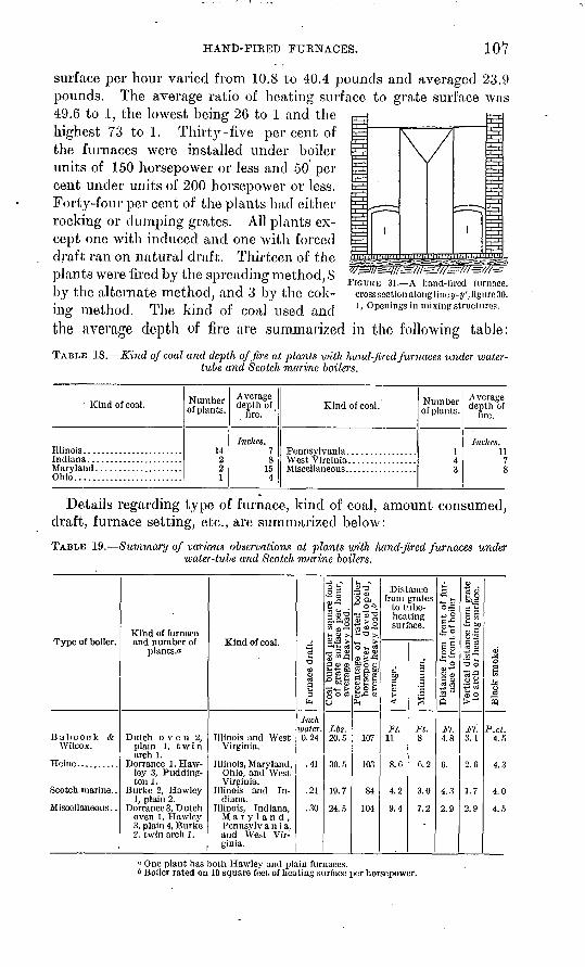
HAND-FIRED FURNACES. 107
surface per hour varied from 10.8 to 40.4 pounds and averaged 23.9 pounds. The average ratio of heating surface to grate surface was 49.6 to 1, the lowest being 26 to 1 and the highest 73 to 1. Thirty-five per cent of the furnaces were installed under boiler units of 150 horsepower or less and 50 per cent under units of 200 horsepower or less. Forty-four per cent of the plants had either rocking or dumping grates. All plants ex cept one with induced and one with forced draft ran on natural draft. Thirteen of the plants were fired by the spreading method, 8 by the alternate method, and 3 by the cok ing method. The kind of coal used and the average depth of fire are summarized in the following table:
TABLE 18. Kind of coal and depth of fire at plants with hand-fired furnaces under coaler- tube and Scotch marine boilers.
FIGURE 31. A hand-fired furnace, cross section along lino y-y', figure 30. 1, Openings in mixing structures.
Kind of coal.
Illinois.......................Indiana......................
Ohio.........................
Number ofplants.
14221
Average depth of
fire. '
Inches.7S
15
Kind of coal. Number ofplants.
1
Average depth of
fire.
Inches. 11
7
Details regarding type of furnace, kind of coal, amount consumed, draft, furnace setting, etc., are summarized below:
TABLE 19. Summary of various observations at plants with hand-fired furnaces under water-tube and Scotch marine boilers.
Type of boiler.
B a b c o c k &Wilcox.
Heine..........
Scotch marine. .
Miscellaneous..
Kitad of furnaceand number of
plants.a
Dutch oven 2,plain 1, twinarch 1.
Dorrance 1 , Hawley 3, Pudding-ton 1.
Burke 2, Hawley1, plain 2.
Dorrance 3, Dutchoven 1, Hawley3, plain 4, Burke2. twin arch 1.
Kind of coal.
Illinois and WestVirginia.
Illinois, Maryland,Ohio, and WestVirginia.
Illinois and Indiana.
Illinois, Indiana,Maryland,Pennsylvan ia,and West Virginia.
2 o
e3
P*H
Inchwater.0.24
.41
.21
.30
Is o2* .03 intl§ &!f o>
*3£ft* Ea v%£ 2 aes&P 03 c3^&s§ O 03O
Lbs.20.5
30. 5
19.7
24.5
U ».S'O
2 8, " 0«. o'ffl'g*s;°2^~
"S * sa) v<c fefiI'&i
a^2QJ £H (DS ° S-55 fl «
PH
107
303
84
104
Distancefrom grates
to tube-heating surface.
0)
20>t><)
JP/.11
S (\ . U
4.2
9.4
g
|'3
S
j-r8
r>. 2
3.0
7.2
t-<
5
o|+» 2 c-00 "SJ- O
+s
IIoqj-w
o a> C o*" H.22ft
7'V.4.8
0.
4.3
2.9
5 ca 02r; oB"SggAM03.9 O-SC C3 ca a)tn"^ ^ *"O o
«-g.2 fc e«03 O( "*"
JF/:3. 1
2.0
1.7
2.9
1o
^ SC3
5
P.c<.4.5
4.3
4.0
4.5
« One plant has both Hawley and plain furnaces.b Boiler rated on 10 square feet of heating surface per horsepower.
108 SMOKELESS COMBUSTION OP COAL.
The draft observations may be briefly summarized thus:
Average furnace draft, 25 plants, 0.29 inch of water; least, 0.07- inch; most, 0.60 inch. Average draft at rear of boiler, 11 plants, 0.54 inch, least, 0.32 inch; most, 0.70 inch. Average draft at base of stack, 19 plants, 0.75 inch, least, 0.50 inch; most, 1 inch. From these readings were deduced the following approximate'draft averages: Approximate average draft in furnace, 0.30 inch of water; at rear of boiler, 0.55 inch, at base of stack, 0.75 inch. This gives an average drop of 0.25 inch of water through the boiler and of 0.20 inch from the boiler to the base of the stack.
Details of the observations at plants with hand-fired furnaces under water-tube and Scotch marine boilers are given in Table 20.
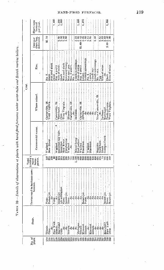
TAB
LE 20.
Det
ails
of
obse
rvat
ions
at
plan
ts w
ith
hand
-fir
ed fu
rnac
es u
nder
wat
er-t
ube
and
Scot
ch m
arin
e bo
ilers
.
No.
of
plan
t.
214
215
216
217
218
219
220
221
222
223
224
225
226
227
228
229
230
231
232
233
234
235
236
237
238
239
240
Sta
te.
....
.do
....
-.--
.-..
....
.
.....d
o.................
.....d
o.................
.....d
o....--
.-.-
...-
...
.....d
o........--
--.-
...
....
.do
....
....
--.-
...-
.
.....d
o.....-
-.--
-.--
.-.
Illi
nois
....
....
....
....
.....d
o.................
....
.do
...-
---.
.-..
....
......d
o.................
. ....d
o. .
...... ...
....
..
Dev
ice
used
to f
acil
itat
e co
m
bust
ion.
HI
.....d
o.......................
.....d
o.......................
.....d
o.......................
.....d
o.......................
.....d
o.......................
.....d
o.......................
.....d
o.......................
.....d
o. .
....
....
....
..:.
....
......d
o.......................
.....d
o.......................
.....d
o.......................
.....d
o.......................
Ste
am je
t ...
....
....
....
....
Tot
al
buil
der
s ra
ted
hors
e
pow
er.
450
825
100 80
90
0 42
4 32
5 50
0 20
0
711
200
1,50
0 50
0 90
0 90
0 60
0 54
0 50
0 45
0
856
200 75
765
600
150
Coa
l. :
Com
mer
cial
nam
e.
.....d
o...................
Blo
ck
....
....
....
....
...
Geo
rges
Cre
ek..
.........
Whe
re m
ined
.
Car
terv
ille
, 11
1 ..............
Wes
t V
irgi
nia.
...
....
....
...
Ohio
........................
....
.do
....
....
....
....
....
...
Car
terv
ille
. 11
1....
... ...
....
......d
o.......................
Car
terv
ille
, 11
1 ............'...
....
.do
....
....
....
....
....
...
....
.do
....
....
....
....
....
...
.....d
o.......................
.....d
o.......................
.....d
o.......................
.....d
o.......................
Mar
y la
nd ...................
Size
.
No.5
...................
Sla
ck..................
Sla
ck...................
Sla
ck..................
No.
2........ ...........
No.
4.. ...
....
..........
Kgg
.....d
o..................
Sla
ck..................
Cos
t per
sh
ort
ton,
de
live
red.
S2. 1
0
2.80
2.
00
2.50
3.60
2.25
2.85
S2
. 60-
2. 6
52.
05
1.80
2.
652.
05
2.60
2.85
3.
60
3.02
2.
00-
2. 4
0 2.
00
Sho
rt t
ons
burn
ed
per
year
.
1,40
0
1,94
0 5,
000
1,55
0
6,42
0
9,80
0
o CD
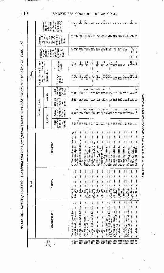
TAB
LE 2
0.
Det
ails
of o
bser
vatio
ns a
t pl
ants
with
han
d-fir
ed fu
rnac
es u
nder
wat
er-t
ube
and
Scot
ch m
arin
e 'b
oile
rs C
onti
nued
.
No.
of
plan
t.
214
215
216
217
218
219
220
221
222
223
224
225
226
227
228
229
230
231
232
233
.234
23
5 23
6 23
7 23
8 23
9 24
0
Loa
d.
Req
uire
men
t.
....
.do..
....
................
....
.do..
....
................
....
.do..
....
................
....
.do..
....
................
....
.do..
....
................
....
.do..
....
................
....
.do..
....
................
....
.do..
....
................
....
.do
....
....
....
....
....
....
...d
o..
....
................
Nat
ure.
..... d
o... ..............
. ...
.do..
.......... ..
...
.-...d
o.................
....
.do
....
....
--.-
-...
.
.....d
o. ................
.....d
o. ..
. ..
....
....
...
.---
.do.................
....
.do
....
....
....
....
.. -
...d
o..
....
... ..
....
...... .do..... ..
....
....
..
....
.do
....
....
....
....
.
.....d
o... ..
....
....
....
...-
.do.................
Cha
ract
er.
Off
ices
and
man
ufac
turi
ng.
. O
ffic
e buil
din
g........ ...
...
Ho
tel.
....
....
....
....
....
..
Hote
l.......................
Hote
l.......................
I*ri
ntin
K o
ffic
eH
ote
l.......................
Rat
ing.
Ave
rage
load
.
Hea
vy.
Hou
rs
per d
ay
load
is
on
plan
t.
10
12 9C
12
24
12
17
12
17
24
24
11
24
12 8
u 17
24
10
10
10
.5
18
11
12
10
17
17
11
Coa
l bu
rned
pe
r da
y (s
hort
to
ns).
11
10 1.9
2 19 6.2
15 7.5
4.3
20
22 3.5
GO 4.9
12.5
12
12
5 8.8
6 1C
18 6.5
3 14
20 2.5
Lig
ht.
Hou
rs
per
day
load
is
on
plan
t. 10
12 12
24
12
17 17
24
24
14
24
12
24 24
10
10
10
18
11
12
10
17
17
11
Coa
l bu
rned
pe
r da
y (s
hort
to
ns).
9 10 1 16 4.8
7.4
3.5
8 15.5
3.
25
60 3.7
20 15 3 6 3 16 8 5 2 14
17 2.5
Coa
l bu
rned
pe
r sq
uare
fo
ot
of
grat
e pe
r ho
ur
(pou
nds)
.
Ave
rage
he
avy
load
.
30.6
17
.1
17.4
16
.7
35
18.3
36
.8
32 17
25.5
14
31
10
.8
33.9
I9
916
.2
31
34
29
32
40.4
20
28
14
.2
14.7
12
.7
Ave
rage
lo
ad.
27.8
17
.1
12.5
32
.1
16.3
27
.5
16
/ 21
.5
10
31 9.5
26 13.4
25
28
.5
27
32
40
18
24
14.2
13
.3
12.7
Per
cent
ag
e of
bo
iler
ho
rse
po
wer
de
vel
op
ed o
n av
erag
e he
avy
load
." 140 74
71
14
3 10
0 11
5 95
140 63
90
97
81
100 50
93
57
76
111
170 97
112
160
108 60
Per
cent
ag
e of
bu
ilde
r's
rate
d ho
rse
po
wer
de
vel
op
ed o
n av
erag
e he
avy
load
. 147 68
80
18
6 10
6 10
9 10
9 12
5 63
66
80
64
132 36
10
4 47
80
111
141 97
11
8 15
3 10
8 16
0 79
79
61
Ass
umed
am
ount
of
coa
l bu
rned
pe
r hor
se
pow
er
per
hour
(p
ound
s).
5 4.
5 5 4.5
5 4.5
5 4 4 5 5 5 5 4.5
5 5 5 5 5 5 5 5 5 5 4.5
5 5
t Boi
ler
rate
d o
n 10
squ
are
feet
of h
eati
ng s
urfa
ce p
er h
orse
pow
er.
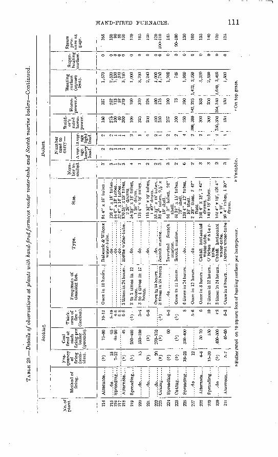
TAB
LE 2
0.
Det
ails
of o
bser
vati
ons
at p
lant
s ^u
ith h
and-
fire
d fu
rnac
es u
nder
roo
ter-
tube
and S
cotc
h m
arin
e b
oil
ers
Con
tinu
ed.
No.
of
pla
nt.
214
215
216
217
218
219
220
221
222
223
224
225
226
227
228
229
230
231
Sto
king
.
Met
hod
of
firi
ng.
Alt
erna
te. .
. .
.....d
o.......
Spr
eadi
ng .
. .
Alt
erna
te. .
. .
Spr
eadi
ng .
. .
....
.do..
....
.
.....d
o.......
....
.do..
....
.C
okin
g..
....
Spr
eadi
ng. .
.
Spre
adin
g..;
....
.do .
.....
Alt
ernat
e....
Spre
adin
g...
.....d
o.......
Alt
ern
ate.
...
Fre
qu
ency
of
fi
ring
(m
in
utes
).
CO 15
7-
12
(»)
(6) 15
(6) 20
(*
)
(6)
(6)
18-2
5 12
4-6
15-3
0
(6) 5-
7
Coa
l fi
red
at
each
fi
ring
per
bo
iler
(p
ound
s).
75-9
0 65
60-9
0 45
250-
400
150-
180
(")
270-
370
(6)
60
(»)
350-
400
50-7
0
150
.400
-500
40-6
0
Thi
ck
ness
of
fire
(inc
hes)
.
10-1
2
S-10
4-
6 6-
8 0-
8
(6)
.
3-4
6-8
(6) 6-
S
(6)
8
5-6 6 10
<=S
6-S
Fre
quen
cy o
f cl
eani
ng f
ire.
Onc
e in
10
hours
..
Boi
lers
.
Typ
e.
Bab
cock
& W
ilco
x w
ater
-tub
e.
.....d
o........
...................... .
....do...........:
......
....
. ....do. ..
....
..
.3
tim
es in
24
hour
s .
2 to
3 t
imes
in
12
hour
s.
3 to
4 t
imes
in
17
hour
s.
3 ti
mes
in
24 h
ours
.....d
o.............
Onc
e in
11
hours
. .
6 ti
mes
in 2
4 hours
.
Onc
e in
S h
ours
...
2 ti
mes
in 1
2 ho
urs
.
3 ti
mes
in
24 h
ours
.
Onc
e in
8 h
ours
. ..
.
Hei
ne w
ater
-tube.
.....d
o............
.....d
o............
.....d
o............
....
.do
....
....
....
Sco
tch
mar
ine.
....
Inv
erte
d
Sco
tch
mar
ine.
S
cotc
h m
arin
e.....
....
.do
....
....
....
....
.do
....
....
....
Cah
all
hori
zont
al
wat
er-t
ube.
O
'Bri
en
wate
r-
tube
. C
ahal
l ho
rizo
ntal
w
ater
-tub
e.
Det
roit
wat
er-t
ube
Size
.
84 4
" x
16' t
ub
es .
.
120
4" x
18'
tub
es-.
54
4"
x I
S' t
ubes
. ..
32 4
" x
14' t
ubes.
..
170 3
i"x
IS'
tub
es,
2 36
" dr
ums.
54
zy x
IS'
tub
es.
1 36
" dru
m.
176
4" x
IS'
tubes
. .
116
3V
x 1
9' t
ubes
, 1
40"
dru
m.
58 3
i" x
IS
' tubes
..
84 4
" tu
bes,
9iV
x
IS'
shel
l. 94
3"
tu
bes,
94
" sh
ell.
44 3
.V"
x 15
' tu
bes,
78
"" s
hell
. 13
S 4"
x 1
2' t
ubes
, 10
' she
ll.
2 3S
" fl
ues,
2
42"
flue
s.
160
4" x
IS
', 2
42"
drum
s.
140x
18' t
ubes.
....
162
4" x
IS
', 12
0 4"
x
lS'.
96 4
" tu
bes,
1 3
0"
drum
.
Num
be
r in
st
alle
d. 3' 3 1 2 3 4 1 2 2 3 3 2 0 2 3 3 2 3
Num
ber
us
ed t
o ca
rry
Ave
r
age
hea
vy
lo
ad.
' 2 2 1 1 1 2 1 1 2 2 2 2 4 2 2 2 1 1
Ave
r
age
ligh
t lo
ad. 2 2 1 1 1 2 1 1 2 1 2 2 4 2 2 1 2 1
Bui
ld
er's
ra
ted
ho
rse
po
wer
.
150
275
100 40
300
106
325
250
100
250
237
100
250
200,
300
300
300
250,
350
ISO
Hor
se-
pow
er.a
157
252
113 52
319
100
370
224
100
175
190 75
190
142.
225
335
250
264,
340
ISO
Hea
tin
g
surf
ace
(squ
are
fe
et). 1,57
0
2,52
0 1,
130
520
3,18
5
1,00
0
3,70
0
2,24
0
1,00
0 1,
750
1,90
0
746
1,90
0
1,42
3,
2,25
0
3,35
0
2,50
0
2,64
0, 3
,400
1,80
0
Sup
er
hea
tin
g
surf
ace. 0 0 0 0 0 0 0 0 0 0 0 0 0 0 0 0 0 0
Ste
am
pres
su
re a
t ga
ge.
" 16
5
150 90
80
15
0
120
105
150
120
100-
110
145
90-1
00
130
100
135
110
120
125
»B
oil
erra
ted
on 1
0 sq
uare
fee
t of
hea
ting
sur
face
per
hor
sepo
wer
.6
Var
iable
.O
n to
p gr
ate.
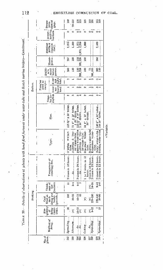
TAB
LE 20.
Det
ails
of o
bser
vati
ons
at p
lants
wit
h ha
nd-f
ired
furn
aces
und
er w
ater
-tii
be a
nd S
cotc
h m
arin
e boil
ers
Con
tinu
ed.
No.
of
plan
t.
232
233
234
235
236
237
238
239
240
Sto
king
.
Met
hod
of
firi
ng.
Spre
adin
g...
Alt
ernat
e....
....
.do..
....
...
...d
o..
....
.
Cokin
g..
....
....
.do..
.....
Spr
eadi
ng .
. .
Fre
qu
ency
of
fi
ring
(m
in
ute
s).
20
(a}
10
-15
(a)
(a)
(a)
8-12 10
Coa
l fi
red
at
each
fi
ring
per
bo
iler
(pou
nds.
)
100
30-3
5
60-7
5A
Z*
(a)
(a)
120-
150
50-9
0
Th
ick
ne
ss o
f fi
re
(inc
hes)
.
11 3-4
A
C
(a)
14-1
6
9 I
95-
6
Fre
qu
ency
of
clea
nin
g f
ire.
2 ti
mes
in 1
0 ho
urs
.
....
.do
....
....
....
....
.do
....
....
....
hour
s.
2 ti
mes
in 1
1 hours
.
Boi
lers
.
Typ
e. ,
O'B
rien
w
ate
r-tu
be.
lor
wat
er- t
ube.
lor
wat
er-t
ub
e.
tube
.
tube
.
Sti
rlin
g w
ater
-tube
Siz
e.
113
3 £"x
18'
tu
bes
.
72 4
" x
18'
tube
s,1
36"
dru
m
36"
drum
s.
140
4" x
16'
tu
bes
Num
be
r in
st
alle
d. 2 3 4 2 1 3 4 1
Num
ber
carr
y
Ave
rag
e he
avy
load
. 1 1 2 2 1
A'v
er-
light
load
. 2 1 2 2 1
Buil
d
er's
ra
ted
ho
rse- 250
150
i ^n
100 75 onn
150
Hor
se
pow
er.
207
150
158
100
Hea
tin
g
surf
ae e
(s
qu
are
feet
).
2,07
0
1,50
0
1,57
5
1,00
0
2,60
0
Sup
er
heat
ing
surf
ace. 0 0 0 0 0 0 0 0 0
Ste
am
pres
su
re a
t ga
ge. 14
0
90-1
10 125
120
100
150
135
100
a V
aria
ble
.
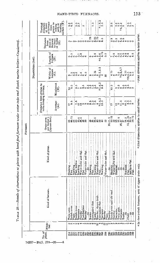
TAB
LE 2
0.
Det
ails
of o
bser
vati
ons
at p
lant
s w
ith
hand
-fir
ed fu
rnac
es u
nder
wat
er-t
ube
and S
cotc
h m
arin
e boil
ers
Con
tinu
ed.
No.
of
plan
t.
214
215
216
217
218
219
220
221
222
223
224
225
226
227
22S
229
230
231
232
233
234
235
236
237
23S
239
240
Fur
nace
s.
Num
be
r. 3 3 1 2 6 4 1 2 2 3 6 2 12 4 6 /2
U 2 3 2 3 3 4 2 1 3 4 1
Kin
d of
fur
nace
.
....
.do.............................
Haw
ley
............................
....
.do
....
....
....
....
....
....
....
.
....
.do.............................
do
Kin
d of
gra
te.
Fla
t...
....
....
....
....
....
....
....
Fla
t...............................
....
.do
....
....
....
....
....
....
....
.
Fla
t.....
....
....
....
....
....
....
..
Fla
t......................:
........
....
.do..
...........................
....
.do..
...........................
.....d
o.............................
.....d
o.. ...
........................
Fla
t...
....
....
....
....
....
....
....
Fla
t.
. ..
.....
...............
Gra
te a
rea
per
boile
r a
(squ
are
feet
).
36
48.7
5 23
20
45
.6
28.2
48
39 48
36
23. G
40
38
46 55
59,G
1.5
33.2
5 52
25
2
7.5
36
,47 27
21
.3
75, 4
1. 2
5 53
.5
35.7
5
Dim
ensi
ons
(fee
t).
Dis
tanc
e fr
om g
rate
s to
tu
be-h
eati
ng s
urfa
ce.
Ave
rage
(A
). 17 8.5 7.5
10
12
3 9 9 8.5
1.5
7.5
4
61.6
,2
12
.5
17 11 9 11.5
9 11
.5
4.5
2.5
5
Min
imum
(B
).
14 5.5 4.5
7 9 2.5
6 6.5
5.5
1.5
5.5
2
61.6
,2
9.5
13.5 9 6.5
8 6.5
9.5
4.5
2 3
Wid
th o
f fu
rnac
e (C
).
3 7.5
3.8
3.3
4 4.
8 8 6
.5
8 3 5.25
8
6 3.
2, 3
. 5
4 10 4.75
8 5 2
.5
65
,8,6
.7
6 4.75
cl
O,5
. 5
8.9
6.5
Len
gth
of
furn
ace
(D). 6 6
.5
6 6 5.7
5.8
6 6 6 6 4.5
5
66,5
.6
5.75
5.5
7 6.5
5 5.5
6.2
4
.5
4.5
7
.5
6 5. 5
Dis
tanc
e fr
om
fron
t of
fu
rnac
e to
fro
nt
of b
oile
r (E
). 5 7 0 7 0 0 0 0 0 7.75
0 6.
25
7.75
0 6.5
3.3
0 6.3
0 6
.5
4.5
5 0 0 0
Ver
tica
l di
stan
ce
at f
ront
of
fur
nace
fr
om
grat
es t
o co
king
ar
ch o
r he
atin
g su
rfac
e (F
).
. 2.
3 '
4.5
2.5
2.2 3 1.5
61
.6,2
2
.5
2.6
2.3
2.2
6 3,
3. 3
2 5
.5
2.5
3
uw 1
a In
dow
n-dr
aft
furn
aces
, ar
ea o
f up
per
grat
e on
ly.
6 F
irst
dim
ensi
on a
ppli
es t
o sm
all
boil
er.
= Fir
st d
imen
sion
app
lies
to
larg
e bo
iler
.C
O
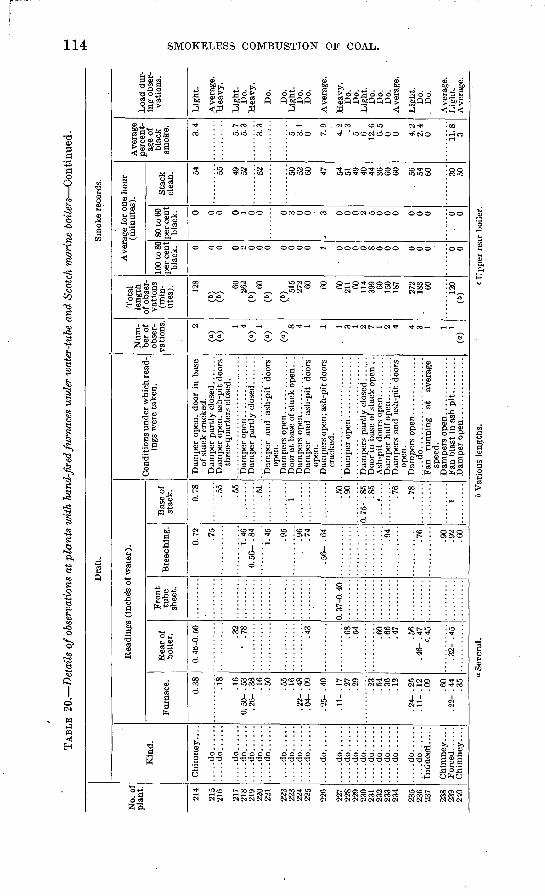
TAB
LE 2
0.
Det
ails
of o
bser
vatio
ns a
t p
lants
wit
h ha
nd-f
ired
furn
aces
und
er w
ater
-tub
e an
d Sc
otch
mar
ine
boil
ers
Con
tinu
ed.
No.
of
pla
nt.
214
215
216
217
218
219
220
221
222
223
224
225
226
227
228
229
230
231
232
233
234
235
236
237
238
239
240
Dra
ft.
Kin
d.
Chim
ney
....
....
.do..
....
....
.do..
....
....
.do
....
.......d
o......
.....d
o......
.....d
o......
....
.do..
....
....
.do..
....
....
.do..
....
.....d
o......
....
.do..
....
.....d
o......
....
.do..
....
....
.do..
....
....
.do..
....
....
.do..
....
....
.do..
....
....
.do..
....
....
.do..
....
....
.do..
....
.....d
o......
....
.do..
....
Induce
'd.....
Chim
ney
....
Chim
ney
....
Rea
ding
s (i
nche
s of
wat
er).
Fur
nace
.
0.38 .18
.16
0.50
- .5
3 .2
6- .
38 .16
.50
.55
.16
. 22-
. 4
8. 0
4- .
09
. 25-
. 4
0
. 11-
. 1
7.2
7 .2
9
.23
.54
.36
.12
. 24-
. 2
5 . 1
1- .
12
.09
.60
. 22-
. 4
4.3
5
Rea
r of
bo
iler.
0. 4
6-0.
50
.32
0 .7
8
.43
.68
.54
.60
.66
.47
.56
. 46-
. 4
7c.
45
. 32-
. 4
5
Fro
nt
tube
shee
t.
0. 3
7-0.
40
Bre
echi
ng.
0.72
.75
1.46
0
.56-
.84
1.45
.95
.96
.74
.56-
.64
.94
.76
.90
.92
.60
Bas
e of
stac
k. 0.78 .55
.55
.51
1 .50
.90
0. 7
5- .
85
.85
.76
.78
1
Con
diti
ons
under
whi
ch r
ead
in
gs w
ere
taken
.
Dam
per
open
, do
or i
n ba
se
of s
tack
cra
cked
.
Dam
per
open
, as
h-pi
t do
ors
thre
e-quar
ters
clo
sed.
Dam
per
and
ash-
pit
door
s op
en.
Doo
r at
bas
e of
sta
ck o
pen.
. .
Dam
per
and
as
h-pi
t do
ors
open
. D
ampe
rs o
pen;
ash
-pit
doo
rs
crac
ked.
Doo
r in
bas
e of
sta
ck o
pen
. .
Dam
pers
an
d a
sh-p
it d
oors
op
en.
Fan
ru
nnin
g
at
aver
age
spee
d.
Sm
oke
reco
rds.
Num
be
r of
ob
ser
va
tion
s. 2
(a)
(a)
1 4(0
)1
(a)
W8 4 1 1 1 3 1 2 7 1 2 4 4 3 1 1 1
(a)
Tot
al
length
of
obs
er
vati
ons
(min
ut
es). 12
8
(")
(")
60
262
(b)
60
(6)
W 51
527
2 60 60 60
211 60
11
4 39
9 60
150
187
272
183 60 120
<*)
Ave
rage
for
one
ho
ur
(min
ute
s).
100
to 8
0 pe
r ce
nt
blac
k. 0 0 0 0 2 0 0 0 0 0 0 0 1
o 0 0 0 8 0 0 0 0 0 0 0 0
80 to
60
per
cen
t bl
ack. 0 0 0 0 1 0 0 0 3 0 0 3 0 0 0 2 5 0 0 0 0 0 0 0 0
Sta
ck
clea
n. 54 55 49
52 52 50
52
60 47 54
51
49
40
44
36
60
60
. 56
54
60 30
50
Ave
rage
pe
rcen
t
age
of
blac
k sm
oke. 3.4
5.7
5.3
3.3
5 3.1
0 7.9
4.2 .3
5 6 12.6
6.
5 0 0 4.
2 2.
4 0 11
.8
3
Loa
d du
r
ing
obse
r
vati
ons.
Lig
ht.
Ave
rage
. H
eav
y.
Lig
ht.
D
o.
Hea
vy
.
Do.
Do.
L
ight.
D
o.
Do.
Ave
rage
.
Hea
vy.
Do.
D
o.
Lig
ht.
Do.
D
o.
Do.
A
vera
ge.
Lig
ht.
D
o.
. D
o.
Ave
rage
. L
ight
. A
vera
ge.
o S
ever
al.
6 V
ario
us l
engt
hs.
c U
pper
rea
r bo
iler
.
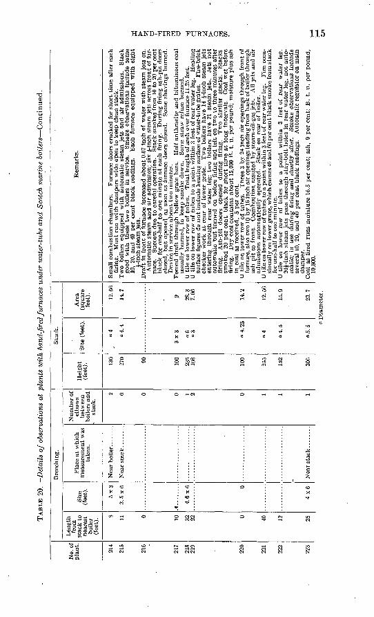
TAB
LE 2
0.
Det
ails
of
obse
rvat
ions
at
plan
ts w
ith
hand
-fir
ed fu
rnac
es u
nder
wat
er-t
ube
and S
cotc
h m
arin
e bo
iler
s^-G
onti
nued
.
No.
of
plan
t.
214
215
216
217
218
219
220
221
222
223
Len
gth
from
st
ack
to
near
est
boile
r (f
eet)
. 8 11 0 10 32 22 0 40 12 28
Size
(fee
t).
3. 5
x6
A..
......
4.6
x6 0
4x6
Bre
echi
ng.
Pla
ce a
t w
hich
m
easu
rem
ent
was
ta
ken.
Num
ber
of
elbo
ws
betw
een
boil
ers
and
- st
ack.
2 0 0 0 1 2 0 1 1 1
Hei
ght
(fee
t). 13
0
270 90 100
235
108
100
152
306
Sta
ck.
Size
(le
et).
04 o4.4
3x
3 "3 o4
.25
04 a4.5
Are
a (s
quar
e fe
et). 12
.56
14.7
.9 28.3
7.06
14.2
12.5
6
15.9
23.7
Rem
arks
.
firi
ng.
Mus
t ru
n w
ith d
ampe
rs w
ide
open
to
keep
cle
an s
tack
. T
wo
boil
ers
equip
ped
w
ith a
uto
mat
ic s
team
jet
s an
d ai
r ad
mis
sion
s.
Sta
ckgo
od
wit
h
thes
e tw
o b
oile
rs i
n se
rvic
e.
Sm
oke
obse
rvat
ions
inc
lude
som
e 10
, 20
, an
d 4
0 pe
r ce
nt
blac
k re
adin
gs.
Eac
h fu
rnac
e eq
uip
ped
wit
h e
igh
t J-
inch
ste
am j
ets.
Auto
mat
ic s
team
and a
ir a
dmis
sion
; si
x J-
inch
ste
am j
ets
acro
ss f
ront
of
fur
na
ce.
Suc
cess
du
e to
car
eful
ope
rati
on.
Sta
ck s
mok
es f
rom
10
to 2
0 pe
r ce
nt
bla
ck f
or o
ne-h
alf
to o
ne m
inu
te a
t ea
ch f
irin
g.
Dur
ing
fir
ing
ash
-pit
doo
rs
clos
ed,
but
open
ed
as s
oon
as f
urna
ce d
oors
clo
sed.
S
ome
shav
ings
bu
rned
. D
evic
e in
ser
vice
about
two
min
ute
s.
usua
lly
bu
rned
, to
kee
p s
mok
e do
wn.
S
ome
stra
w r
efus
e b
urn
ed.
surf
ace
figu
res
do n
ot
incl
ude
hea
ting s
urfa
ce o
f w
ater
-tu
be
grat
es.
Fir
e-br
ick
chec
ker
wor
k at
rea
r of
low
er g
rate
. T
wo
boil
ers
hav
e 14
J-i
nch
stea
m j
ets
ente
ring
th
rough r
ear
wat
er l
eg;
two
boil
ers
have
21
stea
m j
ets.
Je
ts n
ot
auto
mat
ic b
ut
turn
ed o
n be
fore
fir
ing
and
lef
t on
tw
o to
th
ree
min
ute
s af
ter
firi
ng.
Ash
-pit
do
ors
open
ed
duri
ng
firi
ng.
Tw
o si
mil
ar
stac
ks.
Sta
cks
smok
ed 2
0 per
cen
t bla
ck f
or s
hort
tim
e at
lon
g in
terv
als.
C
oal
wet
bef
ore
firi
ng.
Dry
coa
l co
nta
ins
about
15,0
00 B
. t.
u.
per
poun
d; m
ois
ture
plu
s as
h in
coa
l as
rec
eive
d,
5 p
er c
ent.
furn
ace,
als
o tw
o 10
by
16
inch
air
ope
ning
s le
adin
g fr
om b
ack
of b
oile
r th
rou
gh
as
h pit
to
fron
t.
Com
bust
ion a
ssis
ted
by s
team
-oil
-gas
jet
s.
All
jet
s an
d a
ir
adm
issi
ons
auto
mat
ical
ly o
pera
ted.
S
tack
on
rear
of
boil
er.
sion
ally
on
low
er g
rate
, whi
ch c
ause
s 40
and
60
per
cen
t bla
ck s
mok
e fr
om s
tack
fo
r on
e-ha
lf t
o on
e m
inute
.
24£-
inch
ste
am j
ets
pas
s th
roug
h st
ay-b
olt
hole
s in
rea
r w
ater
leg
, not
auto
m
atic
; in
use
duri
ng f
irin
g an
d s
ho
rtly
aft
er.
Sm
oke
obse
rvat
ions
inc
lude
se
vera
l 10
, 20
, an
d 40
per
cen
t bl
ack
read
ings
. A
uto
mat
ic r
egul
ator
on
mai
n
dam
per.
10,8
00.
w > % u *i i i w H
O *4 d w * > a w CO
Dia
met
er.
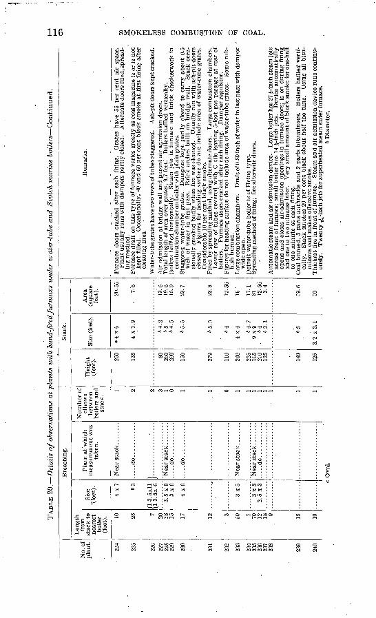
TAB
LE 2
0.
Det
ails
of
obse
rvat
ions
at
pla
nts
wit
h ha
nd-f
ired
furn
aces
und
er w
ater
-tub
e an
d Sc
otch
mar
ine
bo
iler
s C
on
tin
ued
.
No.
of
plan
t.
224
225
227
228
OO
A
231
232
234
oq
c
237
238
239
04O
Len
gth
from
st
ack
to
near
est
boile
r (f
eet)
. 10 7 20 18 15 17 12 3 50 7 70 12 18 9 15 10
Size
'(f
eet)
.
4x
7 63
fl 3
. 5x1
1
3. 5
x9
3x
0
3x
82.5
x3
a
Bre
echi
ng.
Pla
ce a
t 'w
hich
m
easu
rem
ent
was
ta
ken.
....
.do..
....
....
..
}....
......
....:.
...
....
.do
....
....
....
....
.do
..:.
....
....
....
.do..
....
....
..
Ova
l.
Num
ber
of
elbo
ws
betw
een
boile
rs a
nd
stac
k.
1 2 2 3 1 0 1 1 0 1 1 1 1 1 1 1 1
Hei
ght
' (f
eet)
. 250
135 80 200
200'
150
279
110
200
225
105
210
125
140
125
Sta
ck.
Size
(fe
et).
a4 x
6
4 x
1.9
64.2
65 64.5
65.5
64
4x4 64
. 7
9x9 64 62.1
65
3. 2
x 3
. 1
Are
a (s
quar
e fe
et). 20
.50
. 7.
6
13.6
19.6
15.9
23.7
23.8
12. 5
61
6'
17.1
81 12.5
63.
4
19. f
l
10
Rem
arks.
Pla
nt u
sual
ly r
uns
wit
h da
mpe
rs p
artl
y cl
osed
. A
lter
nate
doo
rs f
ired
, spr
ead
in
g m
etho
d.
kept
fill
ed.
Occ
asio
nally
,' 40
and
60
per
cent
bla
ck s
mok
e at
fir
st f
irin
g af
ter
clea
ning
fir
es.
Wat
er- t
ube
grat
es h
ave
two
row
s of
tube
s st
agge
red.
A
sh-p
it d
oors
kep
t cra
cked
.
Tot
al l
engt
h of
arc
h ov
er g
rate
s, 9
.7 f
eet.'
B
oile
rs b
affl
ed v
erti
call
y.B
oile
rs b
affl
ed h
oriz
onta
lly.
S
team
jet
s in
fur
nace
and
bri
ck c
heck
erw
ork
inco
mbu
stio
n ch
ambe
r on
boile
r wit
h pl
ain
grat
es.
inch
of
wat
er i
n fi
rst
pass
. B
rick
arc
hes
buil
t on
bri
dge
wal
l. S
tack
occ
a
sion
ally
sm
oked
bad
ly w
hen
fire
was
cle
aned
. U
sual
ly r
un w
ith
ash-
pit
door
s cl
osed
. F
igur
es f
or h
eati
ng s
urfa
ce d
o no
t in
clud
e ar
ea o
f w
ater
-tub
e gr
ates
. C
onsi
dera
ble
10 p
er c
ent
blac
k sm
oke.
F
ired
by
spre
adin
g m
etho
d, u
sing
alt
erna
te d
oors
. L
arge
com
bust
ion
cham
bers
.L
ower
row
of
tube
s co
vere
d w
ith
C til
e le
avin
g 5-
foot
gas
pas
sage
at
rear
of
boile
rs.
Fur
nace
doo
rs c
rack
ed a
fter
eac
h fi
ring
. D
ampe
r re
gula
tor.
bish
bur
ned.
wid
e op
en.
Aut
omat
ic s
team
and
air
adm
issi
on d
evic
e.
Lar
ge b
oile
r has
27
J-in
ch s
team
jets
acro
ss f
ront
of
furn
ace;
sm
all
boile
r ha
s 14
J-i
rich
jet
s.
Dev
ice
auto
mat
ical
ly
open
s an
d cl
oses
air
-adm
issi
on o
peni
ngs
in f
urna
ce d
oors
; is
on
duri
ng f
irin
g an
d on
e to
tw
o m
inut
es l
ater
. V
ery
smal
l am
ount
of b
lack
sm
oke
for
one-
half
to
one
min
ute
at e
ach
firi
ng.
cally
. S
tack
sm
okes
20
per
cent
bla
ck a
bout
hal
f th
e ti
me.
U
sing
all
bitu
m
inou
s co
al m
akes
off
ensi
ve s
mok
e.
ousl
y.
Tw
enty
5̂-
inch
jets
for
sup
erhe
ated
ste
am e
nter
fur
nace
. 6
Dia
met
er.
HAND-FIRED FURNACES. ' 117
Plants with return tubular boilers. The size of the 44 plants having hand-fired furnaces under return tubular boilers varied widely, the smallest being 50. horsepower and the largest 1,000 horsepower. At 45 per cent of these plants run-of-mine, egg, or lump coal was burned. The cost of coal at 31 plants averaged $2.49 per ton, ranging from $1.60 to $4.10. Uniform loads were carried by 34 plants and varied loads by 10. On the average 90 per cent of the rated boiler horse power (boiler rated on 10 square feet of heating surface per horse power) was developed on mean heavy load. The furnaces in use at the different plants included 10 types, as follows:
Furnaces used at plants with hand-fired furnaces under return tubular boilers.
Number ofplants.
Dorrance (with Dutch oven).................................... 1Down-draft .................................................... 10McMillan...................................................... 5Twin arch..................................................... 1
. Wooley......................................................... 1Burke (western, with Dutch oven)................................ 2Burke (eastern)................................................. 1Plain.......................................................... 21Cornell economizer. ............................................ 1Puddington.................................................... 1
Of these furnaces, 20 had steam-jet attachments. Eleven were equipped with either rocking or dumping grates. At 33 plants either the spreading or the alternate method of firing was used; 5 plants used the coking method.
The average length of travel of the gases to the tube heating sur face and the height of the combustion chamber are indicated by the following figures:
Average distance from grates to tube heating surface, 44 plants, 16.6'feet; shortest, 13 feet; longest, 24 feet. Average least distance from grates to tube heating surface, 44 plants. 14.2 feet; shortest, 11 feet; longest, 22 feet. Average vertical distance from grates to shell, 31 plants, 2.3 feet; shortest, 1.5 feet; longest, 5 feet. Average ratio of heating surface to grate surface, 44 plants, 45 to 1; lowest, 26 to 1; highest, 67 to 1.
The draft readings taken at these plants may be summarized as follows:
Average furnace draft, 39 plants, 0.23 inch of water; range, 0.03 to 0.55 inch. Average draft at front tube sheet, 15 plants, 0.41 inch; range, 0.27 to 0.68 inch. Average draft in breeching, 25 plants, 0.51 inch; range, 0.22 to 1.42 inches. Average draft at base of stack, 16 plants, 0.66 inch; range, 0.35 to 1.10 inches.
The following approximate draft averages were deduced from the above: Furnace, 0.25 inch of water; front tube sheet, 0.40 inch; breeching 0.50 inch; base of stack, 0.70 inch. Approximate average drop through the boiler, 0.15 inch.
For convenience the furnaces and devices in use at these plants are discussed in* three groups down-draft furnaces, steam jets, and mis cellaneous furnaces and devices.
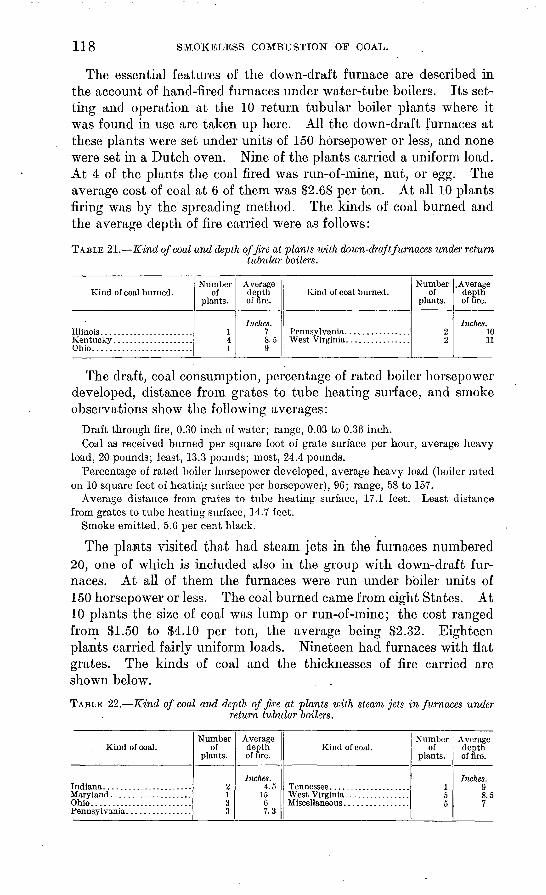
118 SMOKELESS COMBUSTION OF COAL.
The essential features of the down-draft furnace are described in the account of hand-fired furnaces under water-tube boilers. Its set ting and operation at the 10 return tubular boiler plants where it was found in use are taken up here. All the down-draft furnaces at these plants were set under units of 150 horsepower or less, and none were set in a Dutch oven. Nine of the plants carried a uniform load. At 4 of the plants the coal fired was run-of-mine, nut, or egg. The average cost of coal at 6 of them was $2.68 per ton. At all 10 plants firing was by the spreading method. The kinds of coal burned and the average depth of fire carried were as follows:
TABLE 21. Kind of coal and depth of fire at plants with down-draft furnaces under returntubular boilers.
Kind of coal burned.
Ohio.........................
Number of
plants.
141
Average depth of lire.
Inches.78.59
Kind of coal burned.Number
of plants.
22
.Average depth of fire.
Inches. 1011
The draft, coal consumption, percentage of rated boiler horsepower developed, distance from grates to tube heating surface, and smoke observations show the following averages:
Draft through fire, 0.30 inch of water; range, 0.03 to 0.36 inch.Coal as received burned per square foot of grate surface per hour, average heavy
load, 20 pounds; least, 13.3 pounds; most, 24.4 pounds.Percentage of rated boiler horsepower developed, average heavy load (boiler rated
on 10 square feet of heating surface per horsepower), 96; range, 58 to 157.Average distance from grates to tube heating surface, 17.1 feet. Least distance
from grates to tube heating surface, 14.7 feet.Smoke emitted, 5.6 per cent black.
The plants visited that had steam jets in the furnaces numbered 20, one of which is included also in the group with down-draft fur naces. At all of them the furnaces were run under boiler units of 150 horsepower or less. The coal burned came from eight States. At 10 plants the size of coal was lump or run-of-mine; the cost ranged from SI.50 to $4.10 per ton, the average being $2.32. Eighteen plants carried fairly uniform loads. Nineteen had furnaces with flat grates. The kinds of coal and the thicknesses of fire carried are shown below.
TABLE 22. Kind of coal and depth of fire at plants with steam jets in furnaces underreturn tubular boilers.
Kind of coal.
Ohio.........................
Number of
plants.
2133
Average depth of fire.
Inches. 4.5
1567.3
Kind of coal.Number
of plants.
15c
Average depth of fire.
Inches.g8 C
7
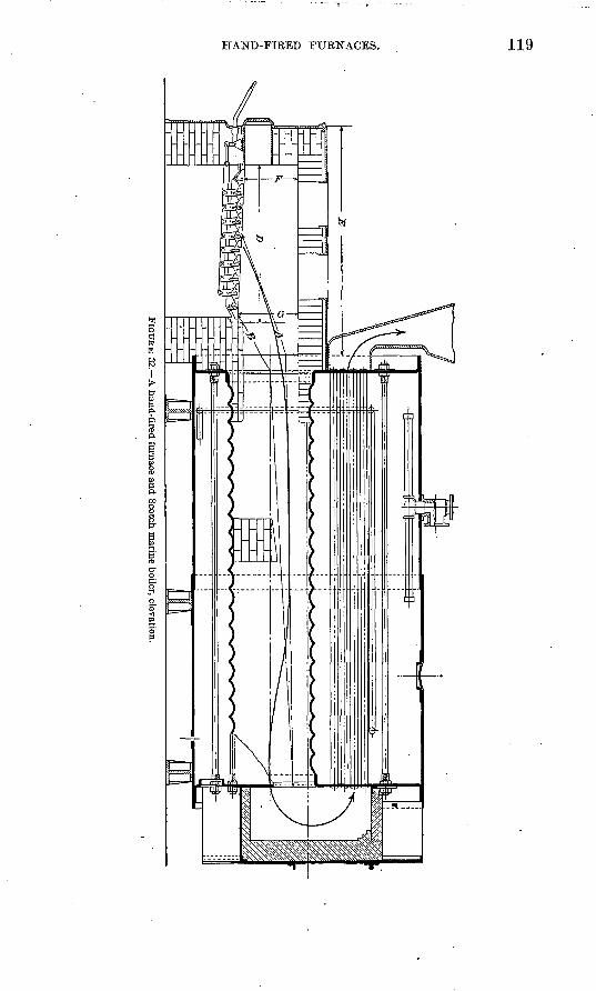
HAND-FIRED FURNACES. 119
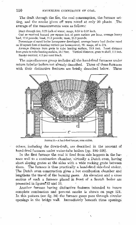
120 SMOKELESS COMBUSTION OF COAL.
The draft through the fire, the coal consumption, the furnace set- ting, and the smoke given off were noted at only 20 plants. ,The average of the measurements were as follows:
Draft through fire, 0.23 inch of water; range, 0.15 to 0.37 inch.Coal as received burned per square foot of grate surface per hour, average heavy
load, 17.6 pounds; least, 11.2 pounds; most, 25.3 pounds.Percentage of rated boiler horsepower developed, average heavy load (boiler rated
on 10 square feet of heating surface per horsepower), 78: range, 46 to 174.Average distance from grate to tube heating surface, 15.9 feet. Least distance
from grate to tube heating surface, 13.7 feet. Vertical distance, grate to shell ,2.2 feet.Smoke emitted, 4.2 per cent black.
The miscellaneous group includes all the hand-fired furnaces under return tubular boilers not already described. Three of these furnaces with their distinctive features are briefly described below. Three
FIGURE 33. A hand-fired furnace, cross section.
others, including the down-draft, are described in the account of hand-fired furnaces under water-tube boilers (pp. 104-106).
In the first furnace the coal is' fired from side hoppers in the fur nace wall to a combustion chamber,' virtually a Dutch oven, having short sloping grates at the sides with a wide rocking grate between them. The furnace is thus practically a hand-fired side-feed stoker. The Dutch oven construction gives a hot combustion chamber and lengthens the travel of the burning gases. An elevation and a cross section of such a furnace placed in front of a Scotch boiler are presented in figures*32 and 33.
Another furnace having distinctive features intended to insure complete combustion and prevent smoke is shown on page 121. In this pattern (see fig. 34) the furnace gases pass through circular openings in the bridge wall. Immediately beneath these openings
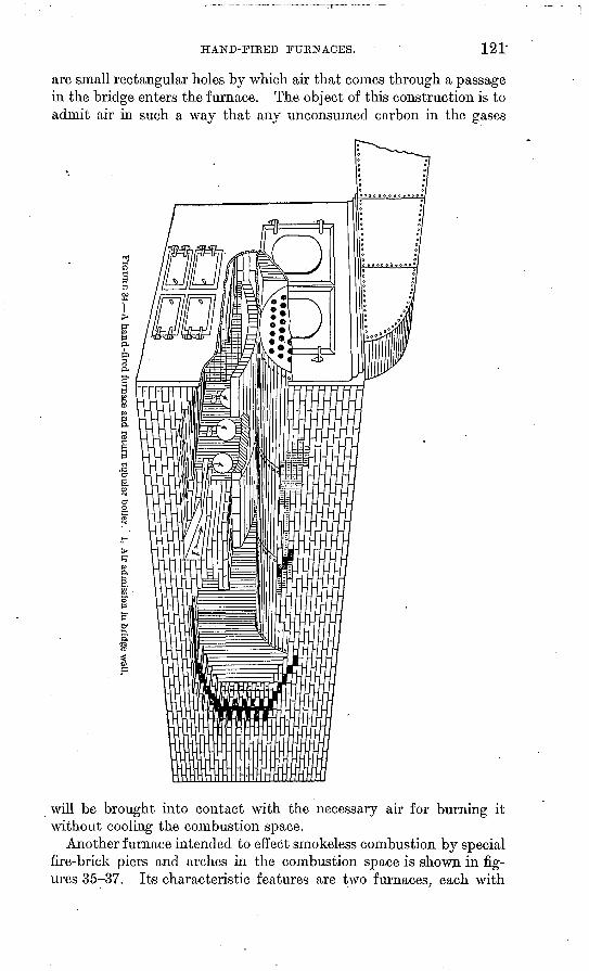
HAND-FIRED FUKNACES. 121
are small rectangular holes by which air that comes through a passage in the bridge enters the furnace. The object of this construction is to admit air in such a way that any unconsumed carbon in the gases
will be brought into contact with the necessary air for burning it without cooling the combustion space.
Another furnace intended to effect smokeless combustion by special fire-brick piers and arches in the combustion space is shown in fig ures 35-37. Its characteristic features are two furnaces, each with
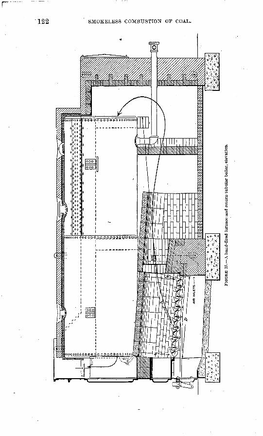
to
to
FIG
UR
E 3
5.
A h
and-
flre
d fu
rnac
e an
d re
turn
tub
ular
boi
ler,
ele
vati
on.
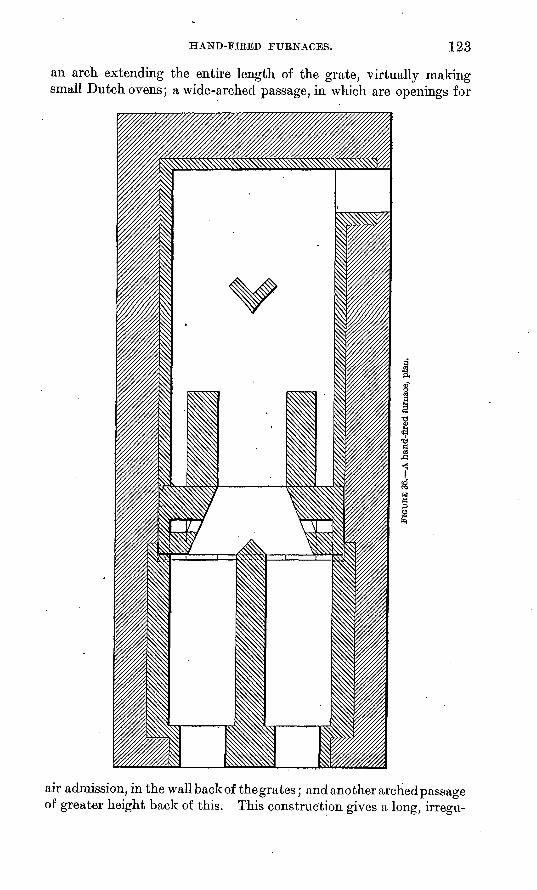
HAND-FIRED FURNACES. 123
an arch extending the entire length of the grate, virtually making small Dutch ovens; a wide-arched passage, in which are openings for
air admission, in the wall back of thegrates; and another archedpassage of greater height back of this. This construction gives a long, irregu-
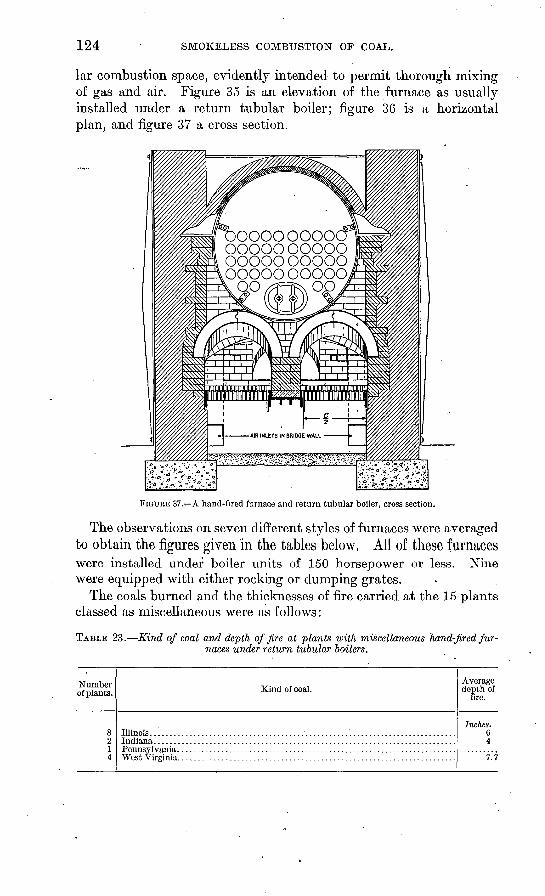
124 SMOKELESS COMBUSTION OF COAL.
lar combustion space, evidently intended to permit thorough mixing of gas and air. Figure 35 is an elevation of the furnace as usually installed under a return tubular boiler; figure 36 is a horizontal plan, and figure 37 a cross section.
oooooooo oooooooooo oooooooooo ooooooooooO
FIGUKE 37. A hand-fired furnace and return tubular boiler, cross section.
The observations on seven different styles of furnaces were averaged to obtain the figures given in the tables below. All of these furnaceswere installed under boiler units of 150 horsepower or less. Nine were equipped with either rocking or dumping grates.
The coals burned and the thicknesses of fire carried at the 15 plants classed as miscellaneous were as follows:
TABLE 23. Kind of coal and depth of fire at plants with miscellaneous hand-fired fur naces under return tubular boilers.
Number of plants.
8214
Kind of coal.Average depth of
fire.
Inches. 64
7.7
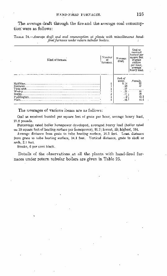
HAND-FIRED FURNACES. 125
The average draft through the fire and the average coal consump tion' were as follows:
TABLE 24. Average draft and coal consumption at plants with miscellaneous hand- fired furnaces under return tubular boilers. :
Kind of furnace.
Puddington. . ........................................................
Number of
furnaces.
111214
Furnace draft.
Inch ofwater.
0.14.23.27
.21.11.12.28
Coal asreceived
burned persquare foot
of grate surface
per hour,average
heavy load.
Pounds.2247
1C1813.214. G
The averages of various items are as follows:Coal as received burrfed per square feet of grate per hour, average heavy load,
21.8 pounds.Percentage rated boiler horsepower developed, averaged heavy load (boiler rated
on 10 square feet of heating surface per horsepower), 91.7; lowest, 53; highest, 184.Average distance from grate to tube heating surface, 16.3 feet. Least distance
from grate to tube heating surface, 14.1 feet. Vertical distance, grate to shell or arch, 2.1 feet.
Smoke, 6 per cent black.
Details of the observations at all the plants with hand-fired fur naces under return tubular boilers are given in Table 25.
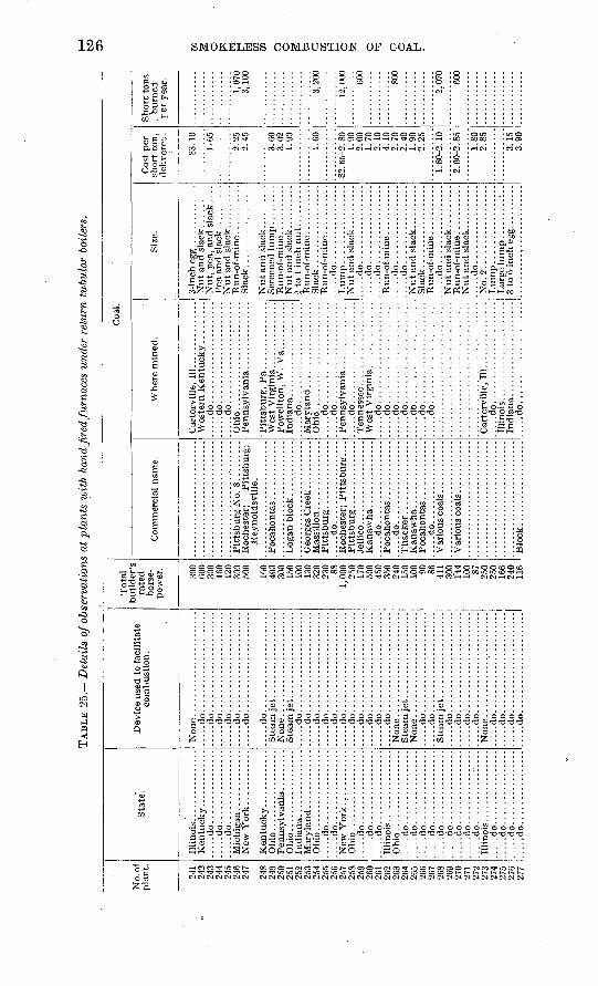
TAB
LE 2
5.
Det
ails
of o
bser
vati
ons
at p
lant
s w
ith
hand
-fir
ed fu
rnac
es u
nder
ret
urn
tubu
lar
boile
rs.
to
No.
of
pla
nt.
241
242
940
245
246
247
248
94Q
251
2 CO
9^**
9^4
occ
9cc
9^7
o C
Q
259
260
262
263
264
9cc
266
267
9AQ
270
271
272
970
274
97c
277
Sta
te.
Illi
no
is......
....
....
..
....
.do
....
....
....
....
....
.do
....
....
....
....
Oh
io..
....
....
....
....
Ohi
o ..........
....
....
....
.do
....
....
....
....
....
.do
....
....
....
....
Ohio
......."
...........
..... d
o..
....
... ...... .
.....d
o........ ........
.....d
o................
Oh
io..
....
..-.
-.-.
-...
.....d
o........-.-
-.-
....
...d
o..
....
....
....
....... d
o... .............
.....d
o........
....
....
.....d
o........
....
....
.....d
o................
.....d
o........
....
....
.....d
o........
....
....
.....d
o...........:
....
Illi
nois
................
.....d
o......
..........
.....d
o. ......
.........
.....d
o......
....
....
.......d
o......
....
....
..
Dev
ice
used
to
faci
lita
te
com
bust
ion.
.....d
o. ..
....
....
....
....
...
....
.do
....
....
....
....
....
....
...d
o..
....
....
....
....
....
....
.do
....
....
....
....
....
....
...d
o..
....
....
....
....
....
....
.do
....
....
....
....
....
..
....
.do
....
....
....
....
....
..
....
.do
....
....
....
....
....
....
...d
o..
....
....
....
....
....
....
.do
....
....
....
....
....
....
...d
o..
....
....
....
....
....
....
.do
....
....
....
....
....
.......d
o. .....................
....
.do
....
....
....
....
....
..
....
.do
....
....
....
....
....
....
...d
o..
....
....
....
....
....
....
.do
....
....
....
....
....
....
...d
o..
....
....
....
....
....
....
.do
....
....
....
....
....
....
...d
o. .................... .
....
.do
....
....
....
....
....
.......d
o. ..
....
....
....
....
...
....
.do
....
....
....
....
....
.......d
o......................
Tot
al
rate
d ho
rse
po
wer
.
300
onn
160
300
500
160
400
300
150
100
1 1
ft
230 88 250
170
cfln
450
350
100 on 86 411
onn
100 87
o e
n
166
116
Co
mm
erci
al n
ame.
Pit
tsb
urg
No
. 8..
....
...
Rey
nold
svil
le.
....
.do
....
....
....
....
..
....
.do
....
....
....
....
..
....
.do
....
....
....
....
..
Blo
ck ...................
Coa
l.
Wher
e m
ined
.
Car
terv
ille
, 11
1... ............
.....d
o......................
.....d
o......................
Ohio
.................:
......
-Pit
tsburg
, P
a...............
Po
wel
lto
n,
W.
Va.
. .........
.....d
o......................
Ohi
o ..
....
....
....
....
....
.......d
o......................
.....d
o....... ...............
....
.do
... ...................
Wes
t V
irgin
ia.. . ..
....
....
.......d
o......................
.....d
o. .....................
.....d
o......................
.....d
o......................
..... d
o..
....
....
...
....
....
......d
o......................
.... .d
o..
....
.. ...
....
....
...
Car
terv
ille
, 111...............
....
.do.
.....................
... ..
do
... ..............:.
...
Size
.
Nu
t an
d sl
ack .........
Run
-of-
min
e ...........
Sla
ck..................
Nu
t an
d sl
ack
....
....
..
Run
-of-
min
e ..
....
....
.N
ut
and
slac
k..
... .....
Run
-of-
min
e ..
....
....
.S
lack
.. ................
.....d
o. ................
....
.do
....
....
....
....
......d
o.. ...
....
....
....
....
.do
....
....
....
....
.
.....d
o........ ...
....
....
...d
o..
....
....
....
...
Nu
t an
d sl
ack ..
....
....
Slac
k ..................
Run
-of-
min
e ...........
....
.do
....
....
....
....
.
Run
-of-
min
e ...........
Nu
t an
d sl
ack.
.. .......
.....d
o. ................
No
.2..
................
Cos
t per
sh
ort
ton,
de
liver
ed.
S3. 1
0
1.65
2.25
2.45
3.60
3.02
1.90
1.60
82. 6
5-2.
80
1.90
2.00
1.70
2.10
4.10
2.70
2.4
01.
902
.25
1. 8
0-2.
10
2. 6
0-2.
85
i.80
2.85
3.15
3.90
Short
tons
. b
urn
ed
rer
yea
r.
1,07
03,
100
:: :
--
3,20
0
12,0
00 600
800
2,07
0
600
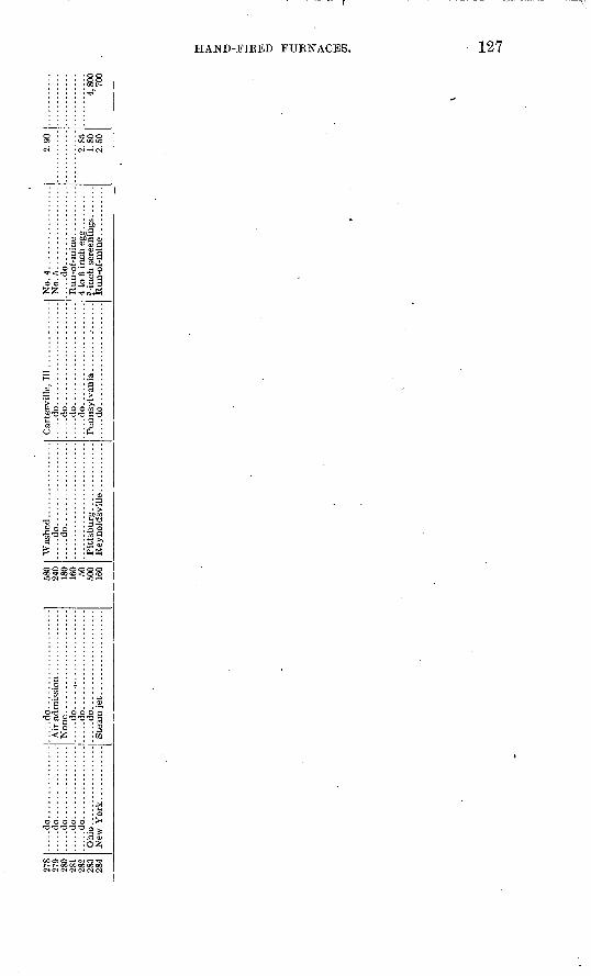
278
280
282
283
284
.....d
o................
.....d
o................
.....d
o................
.....d
o................
.....d
o................
Ohi
o ..
....
....
....
....
.....d
o......................
.....d
o.......................
....
.do
....
...
....
....
....
...
.....d
o......................
580
240
180
160 50 500
160
....
.do
....
....
....
....
....
...d
o..
....
....
....
....
Pit
tsburg
...............
Car
ter-
ville
, II
I ..............
.....d
o......................
.....d
o......................
.....d
o......................
.....d
o......................
.....d
o......................
No.
4........ ...
....
...
....
.do
....
....
....
....
.
2.90
2. 8
51.
802.
504,
800
700
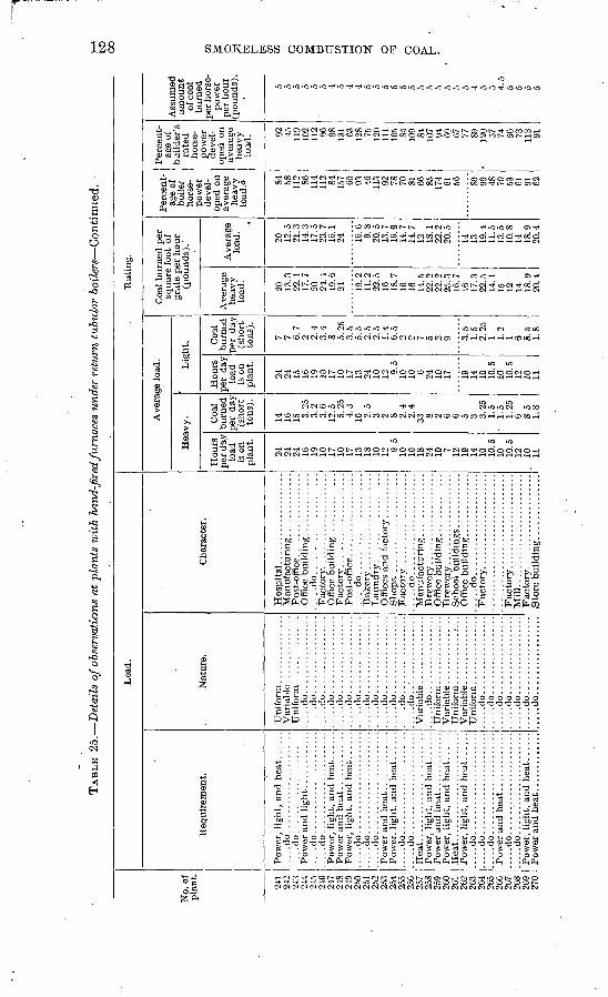
TAB
LE 2
5.
Det
ails
of o
bser
vati
ons
at p
lant
s w
ith
hand
-fir
ed fu
rnac
es u
nder
ret
urn
tubu
lar
boil
ers
Co
nti
nu
ed.
No.
of
plan
t.
241
242
243
244
245
240
247
248
249
250
251
252
253
254
255
250
257
258
259
260
261
262
263
264
265
266
267
268
269
270
Loa
d.
Req
uire
men
t.
.....d
o. ..
....
....
....
....
...
....
.do..
....
................
.....d
o. .....................
....
.do
....
....
....
....
....
..
.....d
o......................
....
.do
....
....
....
....
....
.......d
o......................
.....d
o......................
Heat.
....
....
....
....
....
...
Pow
er,
ligh
t, an
d he
at. ..
...
Heat.
....
....
....
....
....
...
.....d
o. .....................
....
.do..
....
................
.....d
o......................
....
.do
....
....
....
....
....
....
...d
o..
....
................
Pow
er a
nd h
eat .
............
Nat
ure.
....
.do..
....
....
....
...
.....d
o.................
....
.do..
....
....
....
...
....
.do..
....
....
....
...
....
.do..
....
....
....
...
....
.do..
....
....
....
...
.....d
o.................
.....d
o.................
.....d
o.................
....
.do
....
....
....
....
......d
o.................
.....d
o.................
.....d
o..:.
.............
....
.do
....
....
....
....
.
Var
iabl
e ...............
....
.do
....
....
....
....
...
...d
o..
....
....
....
...
....
.do
....
....
....
....
...
...d
o..
....
....
....
...
....
.do
....
....
....
....
...
...d
o..
....
....
....
...
.....d
o.................
Cha
ract
er.
....
.do
. ..
....
....
....
....
...
.....d
o......................
Mil
l...
....
....
....
..
...
.
Sto
re b
uild
ing ..............
Rat
ing.
Ave
rage
loa
d.
Hea
vy.
Hou
rs
per
day
load
is
on
plan
t.
24
24
24
16
19
10
17
10
17
13
18
10
12 9.5
10
10
18
24
10 7 12
19
14
10
10.5
10
. 1
0.5
12
10
11
Coa
l bu
rned
pe
r da
y (s
hort
to
ns).
14
10
15 3.25
3.
2 3.
6 12
.5
5.25
4.
3 10
2.5
3 2 8 2.4
2.4
33 8 2 6 6 5 3 3.25
1.
5 1.
5 1.
25
6 8.5
1.8
Lig
ht.
Hou
rs
per
day
load
"
is o
n pl
ant.
24
24
15
16
19
10
17
10
17
13
24
10
12 9.5
10
10 6 24
10
17 19
14
10
10.5
10
10
.5
12
10
11
Coa
l bu
rned
pp
r da
y (s
hort
to
ns).
7 7 6.7
2 2.4
3.4
8 5.25
3.
5 5.
5 2.
5 2.
5 1.
4 6.
5 2 2 7 5
. 2 9 3.
5 1.
5 2.
25
1 1.2
1 6 8.5
1.8
Coa
l bu
rned
per
sq
uare
foo
t of
gr
ate
per
hour
(p
ound
s)."
Ave
rage
he
avy
load
.
20
13.3
22
.1
17.7
20
24
.4
19.6
24 19
.2
11.2
22
.5
16
18.7
16
16
14
.5
22.2
22
.2
25.3
16
.7
16
17.3
22
.5
14.1
15
12
14
18
.9
20.4
Ave
rage
lo
ad.
20
12.5
21
.3
14.3
17
.5
23.7
16
.1
24 16.6
9.
8 20
.5
13.7
10
.9
14.7
14
.7
12
18.1
22
.2
20.5
14
13
19.4
11
.5
13.5
10
.8
14
18.9
20
.4
Per
cent
ag
e of
bo
iler
hors
e
pow
er
deve
l
oped
on
aver
age
heav
y lo
ad.o 84
58
11
2 86
114
112 84
157 60
93
46
113 92
78
70
81
66
85
174 61
56 89
99
48
70
53
61
91
62
Per
cent
ag
e of
bu
ilde
r's
rate
d ho
rse
po
wer
de
vel
op
ed o
n av
erag
e he
avy
load
. 92
45
119
102
112 96
98
131 63
12
8 75
120
111
105 84
109 84
107 94
69
67
77
89
12
0 57
74
56
73
113 91
Ass
umed
am
ount
of
coa
l bu
rned
pe
r ho
rse
po
wer
pe
r ho
ur
(pou
nds)
.
5 5 5 5 5 5 4 5 4 4 5 5 5 5 5 5 5 5 5 5 5 5 4 5 5 4.5
5 5 5 5
to GO
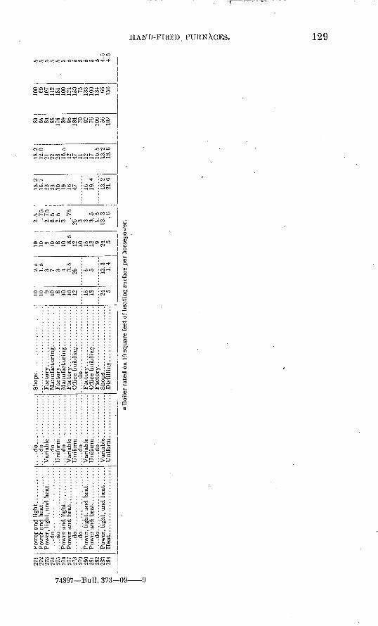
?71
979
O7
0
?74
975
97fi
>77
?'S
279
580
?S1
9«
9?S
39Q
<1
....
.do
....
....
..............
.....d
o..........
....
....
....
.....d
o......................
....
.do
....
....
..............
.....d
o.................
.....d
o.................
.....d
o.................
.....d
o.................
.....d
o.................
.....d
o.................
....
.do
....
....
....
....
....
..
Dis
till
ing...................
10 10 9 10 S 10 10 12 15 18 24
2.5
1.5
3 3 3.5
26 6 is. 3 1.4
10 10 9 10 8 10 8.5
12 10 15 IS 9 24 5
2.5 . 75
2.75
6.5
2.5
3 .75
26 3 3 3.5
1.5
13.3 . G
18.2
16.7
29 23 30 19 16 47 16 19.4
13.2
21.6
18.2
12.6
21 22 28 16.5
12 47 11 12 17 16.5
13.2
18.6
83 65 84 88 176 89 95 184 70 92 76 106 56 102
100 69 107
112
181
100
121
150 75 133
100
134 60 156
5 5 5 5 5 5 o 5 5 5 5 5 4.5
4.5
Boi
ler
rate
d o
n 10
squ
are
feet
of
hea
ting s
urfa
ce p
er h
orse
pow
er.
to CO
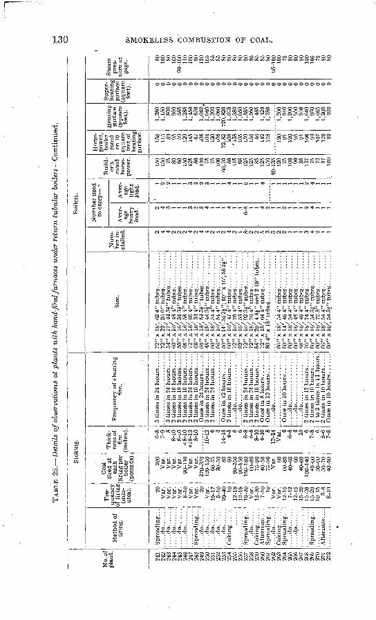
TAB
LE 2
5.
Det
ails
of
obse
rvat
ions
at
pla
nts
wit
h ha
nd-f
ired
furn
aces
und
er r
etur
n tu
bula
r b
oil
ers
Con
tinu
ed.
No.
of
pla
nt.
241
242
243
244
245
246
247
248
249
250
251
252
253
254
255
256
257
258
259
260
261
262
263
264
265
266
267
268
269
270
271
272
Sto
king
.
Met
hod
of
firi
ng.
Spr
eadi
ng. .
.
.....d
o.......
.....d
o.......
.....d
o.......
.....d
o.......
Spr
eadi
ng. .
.
.....d
o.......
.....d
o.......
.....d
o.......
.....d
o.......
Spr
eadi
ng. .
.
Alt
ernat
e....
Spr
eadi
ng. .
.
Spr
eadi
ng. .
. .....d
o.......
.....d
o.......
Spre
adin
g...
Alt
ern
ate.
...
Fre
qu
ency
of
fir
ing
(min
ut
es). 20
V
ar.
Var
. V
ar.
Var
. 8-
10
Var
. V
ar. 20
Var
. 15
-17
5-10
20
-40 10
12
-18
12-1
8 10
-20
Var
. 12
-20
7-10
10
V
ar.
Var
. 12
-15
7-12
12
-15
15-2
0 15
-20
15-2
0 10
-15
3-8
8-10
Coa
l fi
red
at
each
fi
ring
per
bo
iler
(p
ound
s).
200
Var
. V
ar.
Var
. V
ar..
90
-110
V
ar.
Var
. 27
0-37
0 12
0-15
0 50
-75
30-5
0 80
60
90-1
50
90-1
50
150-
180
60-8
0 75
-90
40-5
0 75
-90
Var
. 60
60-8
0 40
-60 60
40
-60
100-
140
40-6
0 50
-60
50-7
0 40
-50
Thi
ck
ness
of
fire
(i
nche
s).
6-8
7-9 8
8-10
8-
10
a 8-
10
alO
-12
8-10
10-1
2 6 3 14
-16
4-5 6 6
6-8
6-8
8-10
4-
10 8
12-1
4 V
ar. 6
6-8 6 10
6 7-
8 6 5-
6 7-
S
Fre
quen
cy o
f cl
eani
ng
fire
.
2 ti
mes
in
16 h
ou
rs. ..
..
2 ti
mes
in
10 h
ours
.....
2 ti
mes
in
24 h
ours
.....
3 ti
mes
in
24 h
ours
.....
2 ti
mes
in
24 h
ours
.....
2 ti
mes
in
10 h
ours
.....
.....d
o..................
.....d
o..................
Onc
e in
8 h
ours
........
Onc
e in
12
hours
.......
.....d
o........
....
....
..
.....d
o..................
.....d
o..................
.....d
o..................
1 to
2 t
imes
in
11 h
ours
. 2
tim
es i
n 10
hours
.....
Onc
e in
10
hours
.......
Boi
lers
.
Size
.
72"
x IS
', 62
4"
tub
es. .
...........
72"
x 2
2',
26 6
" tu
bes
. .............
54"
x 17
', 44
3£"
tub
es. .
....
....
..60
" x
16',
48 4
" tu
bes
. ............
50"
x 1
6',
34 3
J" t
ubes
.. . .........
66"
x 1
8',
58 4
" tu
bes
. ............
72"
x 1
6',
66 4
" tu
bes
. . ...........
60"
x 1
8',
54 3
J" t
ubes
. ...........
48"
x 18
', 48
3i"
tubes
.. . .........
60"
x 18
', 54
4"
tubes
.. . ..........
66"
x 1
6',
54 4
" tu
bes.
............
50"
x 14
', 56
2J"
; 50
" x
16',
56 2
J". .
60
" x 1
6',
47 4
" tu
bes.
............
62"
x 1
6',
53 4
" tu
bes
. ..
....
....
..72
" x 1
6',
92 3
J" t
ub
es. .
..........
54"
x 20
', 4
SJ"
and
2 1
0" t
ubes
. . .
72"
x 1
8',
64 4
" tu
bes
. ............
80 4
" x 1
8' t
ubes
. .................
66"
x 1
8',
54 4
" tu
bes
. ............
60"
x 1
4',
46 4
" tu
bes
. . ...........
60"
x 1
6',
72 3
" tu
bes
. ............
66"
x 1
8',
54 4
" tu
bes
. ...
....
....
.60
" x
16'.
54 3
A"
tub
es. .
..........
Num
ber
in
st
alle
d. 2 4 4 2 2 2 4 2 4 4 2 1 2 4 2 1 8-
2 2 5 3 3 2 2 1 1 1 3 4 2 1 1
Nu
mb
er u
sed
to c
arry
s
Ave
r
age
hea
vy
load
. 2 4 3 1 1 1 3 2 2 4 1 1 1 4 1 1 6-
8 1 1 4 2 1 1 2 1 1 1 2 4 1 1 1
Ave
r
age
lig
ht
load
. 1 2 ' 2 1 1 1 3 2 2 3 1 1 1 4 1 1 6 1 1 4 1 1 1 1 1 1 2 4 1 1 1
Bui
ld
er's
ra
ted
hors
e
pow
er.
150
150 75
80
60
15
0 12
5 80
100 75
75
100
60,7
0 80
115 88
125
125 85
125
150
80-1
35
120 75
10
0 90
86
137 75
72
87
10
0
Hor
se
pow
er,
boil
er
rate
d
on 1
0 sq
uar
e fe
et, o
f he
atin
g su
rfac
e.
138
115 80
95
59
12
9 14
5 67
106
104
120
106
72,8
2 10
8 '1
38
105
159
156 46
'
142
178
120 91
120 95
91
164 93
107
120 92
Hea
ting
surf
ace
(squ
are
feet
).
1,38
0 1,
150
800
950
585
1,28
5 1,
450
670
1,06
0,
1,04
0 1,
200
1,06
0 72
0,82
0 1,
075
1,38
0 1,
050
1,58
5 1,
560
465
1,42
0 1,
780
1,20
0 91
0 1,
200
950
910
1,64
0 93
0 1,
065
1,20
0 92
0
Sup
er
heat
ing
surf
ace
(sq
uar
e fe
et). 0 0 0 0 0 0 0 0 0 0 0 0 0 0 0 0 0 0 0 0 0 0 0 0 0 0 0 0 0 0 0 0
Ste
am
pres
su
re a
t ga
ge. 80
10
0 80
100
90-1
00
110
100 90
120
105 85
85
80
90
80
80
90
95
85
85
80
95
-100
10
0
75
80
90
80
100
105 75
SO
80
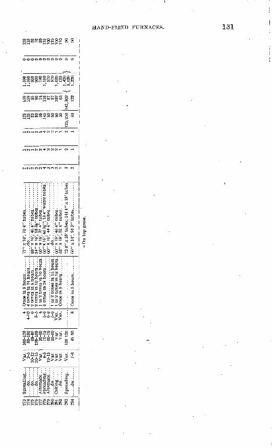
273
274
275
276
277
278
279
280
281
282
283
284
Spre
adin
g.
. .
.....d
o.......
.....d
o.......
.....d
o.......
.....d
o.......
Var
. 2-
510
-12
10-1
5
4-5
12-1
5V
ar.
Var
.V
ar.
Var
.7-
8
100-
120
80-1
0060
-90
120-
180
30-6
070
-75
60-7
030
-60
Var
.V
ar.
100-
120
45-9
0
4 4-
106
3-5 4
5-6
6-8
5-6
Var
.V
ar. 8
Onc
e in
9 h
ou
rs ........
72"
x 1
8',
70 4
" tu
bes
. ............
.....d
o............................
60
" x 1
6',
46 4
" tu
bes
. ............
54
" x 1
6',
52 3
J" t
ubes
. . ...
....
...
60"
x 1
6',
37 4
" tu
bes
. ............
60"x
l8', 4
8 3J"
; 13
4"
wat
er tubes
.6
0"
x 16
', 44
4"
tubes
. ............
.....d
o............................
52"
x 16
', 32
4"
tubes
. . ...........
72 4
" x 1
6' t
ubes
; 14
4 4"
x I
S' t
ubes
06
" x
14',
94 3
" tu
bes
. . ...
....
....
2 2 2 3 2 4 3 3 2 1 3 2
2 1 2 2 4 2 2 2 1 2 1
9 1 2 1 4 2 2 1 1 2 1
125
125 S3 80 58 145 80 60 SO 50
125,
250 SO
159
159 85 90 74 118 87 87 63
142,
302
122
1,59
0 1,
590
850
900
740
1,18
087
087
01,
020
625
/ 1,
420
\ 3,
020
0 0 0 0 0 0 0 0 0 0}
«
125
115 SO 70 SO 125
100
125
160
110 90 90
a O
n to
p g
rate
.
CO
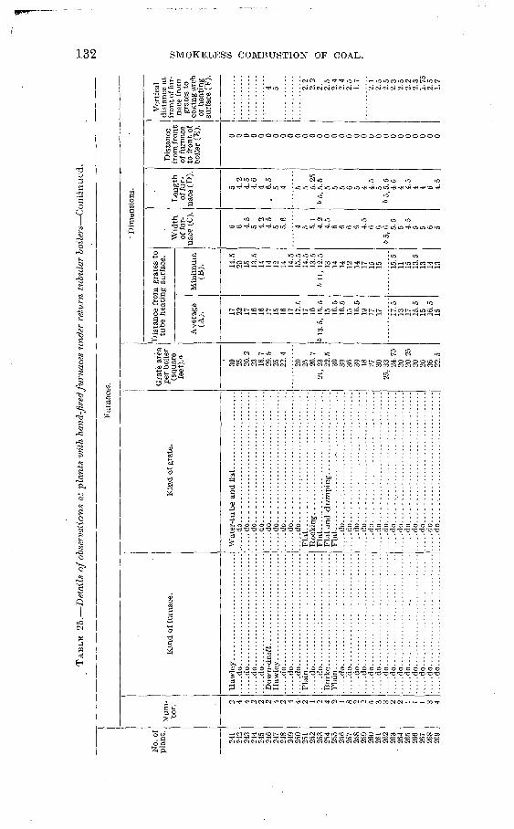
TA
BL
E 2
5.
Det
ails
of
obse
rvat
ions
at
plan
ts w
ith
hand
-fir
ed fu
rnac
es u
nder
ret
urn
tubu
lar
boil
ers
Co
nti
nu
ed.
No.
of
plan
t.
241
242
243
244
245
246
247
248
249
250
251
252
253
254
2-55
25
6 25
7 25
8 25
9 26
0 26
1 26
2 26
3 26
4 26
5 26
6 26
7 26
8 26
9
Fur
nace
s.
Num
ber
. 2 '
4 4 2 2 2 4 2 4 4-
2 1 2 4 2 1 8 2 2 5 3 3 2 2 1 1 1 3 4
Kin
d of
fur
nace
.
.....d
o..............................
.....d
o..............................
....
.do
....
....
....
....
....
....
....
....
...d
o..
....
....
....
....
....
....
....
....
.do
....
....
....
....
....
....
....
....
...d
o..
....
....
....
....
....
....
....
....
.do
....
....
....
....
....
....
....
.......d
o.....-
-....:
......-.
..........
Pla
in ...............................
.....d
o..............................
....
.do
....
....
....
....
... ..
....
....
....
.do
....
....
....
....
....
....
....
....
...d
o..
....
. ..
....
....
....
....
....
.do
Kin
d of
gra
te.
....
.do..
....
....
....
....
....
...
....
...
....
.do..
....
....
....
....
....
...
........
....
.do..................................
.....d
o..................................
.....d
o... ..
....
....
....
....
....
..
...
...
...d
o..................................
.....d
o..
. ...............................
....
.do..................................
.....d
o.........................
....
.F
lat.
....
....
...!
....
....
....
....
....
...
Fla
t....................................
Fla
t...
....
....
....
....
....
....
....
....
.......d
o.... ..............................
..;..
do...
...
....
....
....
....
....
....
....
.....d
o..................................
....
.do
....
...
....
....
....
....
.. ..
....
..d
o...
. .
. .....
. . . .
. do ............................... I
. . -
. d
o ...
. _
. . . .
...
.....
...
.....d
o..............................
.....d
o..............................
.....d
o..............................
....
.do
....
....
....
....
....
....
....
.......d
o..............................
.....d
o...... ...
....
....
....
....
....
......d
o..............................
.....d
o..............................
...
.do.... ............... ..
...
.......
.....d
o.... ..................... ..
...
......d
o.... ..'............................
.....d
o.... ..............................
.....d
o.... ..............................
.....d
o.......................... ..
....
.......d
o.... ..............................
.....d
o.... ..............................
Gra
te a
rea
per
boile
r (s
quar
e fe
et).
»
30
25
20.2
23
16
.7
29.5
25
22
.4
20
25
20.7
21
, 23
22
.5
30
30
36
30
18
27
30
25
,33 24
.75
20
20.2
5 20
20
36
22
.5
Dim
ensi
ons.
Dis
tanc
e fr
om g
rate
s to
tu
be h
eati
ng s
urfa
ce.
Ave
rage
(A
). 17
22
17
16
16
17
15
16
17
17. C
17
16
6
13.5
, 15
.5
15
16.5
16
.5
15
16.5
19
17
17 17
.5
13
17
15.5
15
16
.5
15
Min
imu
m
(B). 14
.5
20
15
13.5
14
14
12
-
14
14.5
15
.5
14.5
13
.5
6 11
, 12
.5
13
14
14
12
14
17
15
15 15.5
11
15
13
.5
13
14
13
Wid
th
of f
ur
nac
e (C
).
6 6 4.5
5 4.2
4.
5 5 5.6 4 5 5.1
4.2
4.
5 6 6 6 6 4.
5 6 6
65
,6 5.5
5 4.5
5 5 6 5
Len
gth
of fu
r
nace
(D
).
5 4.2
4.5
4.6
4
. 6.5
5 4 5 5 5
.25
6
5,5
.5
5 5 5 6 5 4 4.5
5 6
5, 5
. 5
4.5
4 4.5
4 4 6 4.5
Dis
tanc
e fr
om f
ront
of
fur
nace
to
fro
nt o
f bo
iler
(E).
0 0 0 0 0 0 0 0 0 0 0 0 0 0 0 0 0 0 0 0 0 0 0 0 0 0 0 0 0
Ver
tical
di
stan
ce a
t fr
ont o
f fur
na
ce f
rom
gr
ates
to
coki
ng a
rch
or h
eati
ng
surf
ace
(F).
4 5 2.2
2.2
2.
2.
5 2.4
2.
4 2.
5 1.
7
2.1
2.5
2.5
2.3
2.5
2.2
2.3
1.75
2.
5 1.
7
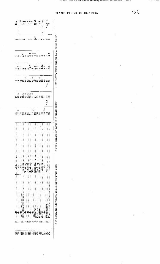
270
271
272
273
274
275
276
277.
278
279
280
281
282
283
284
2 1 1 2 2 2 3 2 4 3 3 2 1 3 1
....
.do.
....
....
....
....
....
....
....
......d
o..............................
.....d
o..............................
....
.do.
....
....
....
....
....
....
....
...
...do.
....
....
....
....
....
....
....
......d
o...................... ........
....
.do.
....
....
....
....
....
....
....
.
Woolle
y...
....
....
....
....
....
....
.
....
.do.
....
....
....
....
....
....
....
.
.....do.....
....
....
....
....
....
....
....
......do..................................
.....do..................................
Flat......
..............................
Flat
....
................................
.....do...
....
....
....
....
....
....
....
...
16
27.5
IS
30
30 9r 21
22.5
23
28
25
19
20. 25
42
25
15
16.5
15
17.5
17.5
15.5
15
.5
17.5
24
15
16
20
21
c3.5
, 14
13
13
14
13
15
14.3
13
13
15
.5
22
12
13.5
IS
19
c3,
11
11
4 5.5
4.5
6 6 5 4.5
5 5.1
2.3
5 4.75
5.1
6 5.5
4 5 4 5 '
5 5 4.7
4.5
4.5
6 5 4 4 7 4.7
0 0 0 0 0 0 0 0 7.7
0 0 5 5 0 0
2.5
1.75
1.5
1.8
1.7
1.7
1.6
2.25
2 2.1
c2.5,
4 o
In d
own-
draf
t fu
rnac
es,
area
of
upper
gra
te o
nly.
6 F
irst
dim
ensi
on a
ppli
es t
o s
mal
l bo
iler
.c
Fir
st d
imen
sion
app
lies
to
tubula
r bo
.!er
.w oo
C
o-
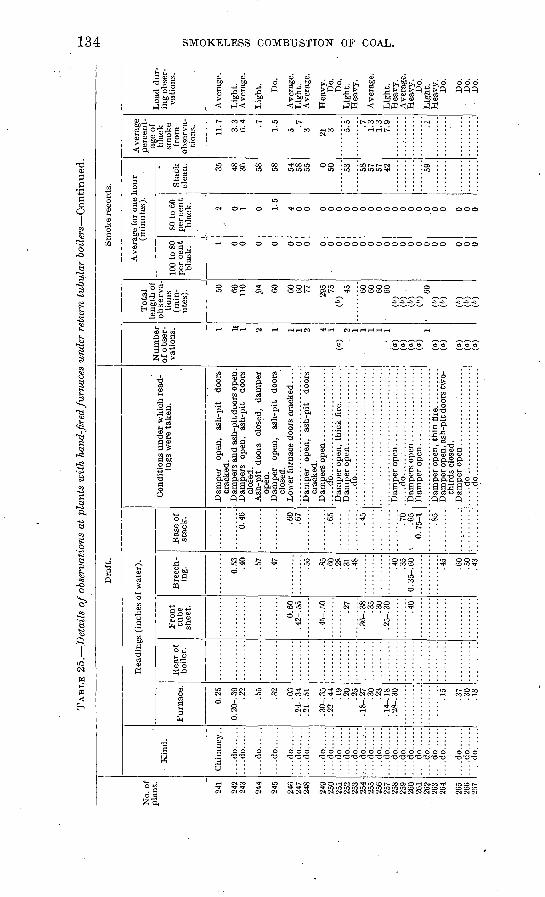
TA
BL
E 2
5.
Det
ails
of
obse
rvat
ions
at
plan
ts w
ith
hand
-fir
ed fu
rnac
es u
nder
ret
urn
tubu
lar
bo
iler
s C
on
tin
ued
.G
O
No.
of
pla
nt.
241
242
243
244
245
246
247
248
249
250
251
252
253
254
255
256
257
258
259
260
261
262
263
264
265
266
2S7
Dra
ft.
K
ind.
....do......
....do......
....do......
....do......
....do......
....do......
....do......
....do......
....do......
....do......
....do......
....do......
.-.-
..do......
....do......
....do......
....do......
....do......
....
do
....
....
..d
o..
....
....
do
....
....
..d
o..
....
....
do
....
......do......
....do......
....
do
....
......do.....
Rea
ding
s (i
nche
s of
wat
er).
Fu
rnac
e.
0.25
0. 2
0-. 3
99
9
.55
.32
.03
. 24-
. 34
.21-
. 51
.30-
. 35
.22-
. 44
.19
.20
.25
. 18-
. 27
.30
.23
. 14-
. 18
. 28-
. 30
.15
.37
.30
.18
Rea
r of
bo
iler
.F
ron
t tu
be
shee
t.
0.60
. 4
2-. 5
5
. 45-
. 50
.27
.35
.30
.25-
. 30
.40
Bre
ech
in
g. 0.53
.4
0
.57
.47
.55
.85
.60
.28
.31
.48
.40
.35
0.35
-.60 .6
0 >;n .43
Bas
e of
st
ack
.
"
"6.4
6"
.60
.67
.65 4=
\
.70
I .6
5 0.
75-
1
.85
Con
diti
ons
unde
r w
hich
rea
d
ings
wer
e ta
ken.
Dam
per
open
, as
h-pi
t do
ors
crac
ked.
, D
ampe
rs a
nd a
sh-p
it d
oors
ope
n.
Dam
pers
op
en,
ash-
pit
door
s cl
osed
. A
sh-p
it
door
s cl
osed
, da
mpe
r op
en.
Dam
per
open
, as
h-pi
t do
ors
clos
ed.
Low
er f
urna
ce d
oors
cra
cked
....
Dam
per
open
, as
h-pi
t do
ors
crac
ked.
....
.do
....
....
....
....
....
....
...
Dam
per
open
...................
....
.do
....
....
....
....
....
....
...
....
.do
....
....
....
....
....
....
...
Dam
per o
pen,
ash
-pit
doo
rs tw
o-
thir
ds c
lose
d .
....
.do
....
....
....
....
....
....
...
Smok
e re
cord
s.
Num
ber
of o
bser
va
tion
s.
(a (a
(a
(a
(a (a
(a (a (°
(a
1 U 2 1 1 1 2 4 1
. 2 1 1 1 1 1 1
-
Tota
l le
ng
th o
f o
bse
rva
ti
ons
(min
ute
s). 50 60
11
0
.94 60 60
60 77 295 75
(»
) 45 60
60
60
60
(6
) ("
) .
(")
(6)
60
(6)
(")
(fc)
(6)
(&)
Ave
rage
for
one
hour
(min
ute
s).
100
to S
O per
cen
t bl
ack.
1 0 0 0 0 0 0 0 0 0 0 0 0 0 0 0 0 0 0 0 0 0 0 0 0 0 0
SO t
o 60
per
cent
blac
k. 2 0 1 0 1.5
4 0 0 0 0 0 0 0 0 0 0 0 0 0 0 0 0 'o 0 0 0 0
Sta
ck
clea
n. 35 48
36 58
58 54
58
55 0 50 53 58
57
57
42 59
Ave
rage
p
erce
nt
ag
e of
b
lack
sm
oke
from
ob
serv
a
tion
s. 11.7
3.3
6.4 .7
1.5
5 .7
3 21 3 5.5 .7
1.3
1.3
7.9 .1
Loa
d dur
in
g ob
ser
va
tion
s.
Ave
rage
.
Lig
ht.
Ave
rage
.
Lig
ht.
Do.
Ave
rage
. L
ight
. A
vera
ge.
Hea
vy.
Do.
D
o.
Lig
ht.
Hea
vy.
Ave
rage
.
Lig
ht.
Hea
vy.
Ave
rage
. H
eav
y.
Do.
L
ight
. H
eavy
. D
o.
Do.
D
o.
D
o.
CO
CO o o % W 3 CO H h-I O
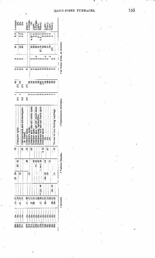
269
270
271
272
273
274
275
276
277
278
279
280
281
282
283
284
....do......
....do......
....do......
....do......
....do......
....do......
....do......
....do......
....do......
....do......
....do......
....do......
....do......
....do......
....do......
....
do
....
..
.20
.27-
. 32
. 17-
. 20
. 12-
. 17
.20-
. 22
.11
.06
.17
.28
.27
.08
. .1
0-. 1
3. 2
4-. 3
3
cO.3
3-.4
8
.32-
. 34
.45
.35
.68
.35
.42-
. 45 .40
.44
. 47-
. 56
.22
1.34
-1.5
0
.64
.45
.35
.52
.62
i.io
.82
.47
ly c
lose
d.
:.. ..
do...
.. ..
....
....
....
....
....
....
.do
....
....
....
....
....
....
...
(a.~) (a~\
(a)
2 1 1 1 2 3 1 1 1 1
(b)
60(b
)
(b)
65 54 60 60 60 395
127 60 60 60 30 60
0 0 0 0 0 2 0 0 0 0 0 0 0 0 0
0 0 0 2 2 3.5
5 0 6 ^ =;
0 .5 0 0
55 50 33 39 38 3557
,54 50 48 57 54
00
2.3 5.6
* 10
.79.
69.
811
.62.
5,. 7
3.8
6.3
2.5
3.4 5
Do.
D
o.D
o.
Do.
Lig
ht.
Lig
ht.
Lig
ht.
Lig
ht.
Hea
vy.
Seve
ral.
b V
ario
us l
engt
hs.
Com
bust
ion
cham
ber.
d 56
wat
er t
ube,
46
tubu
lar.
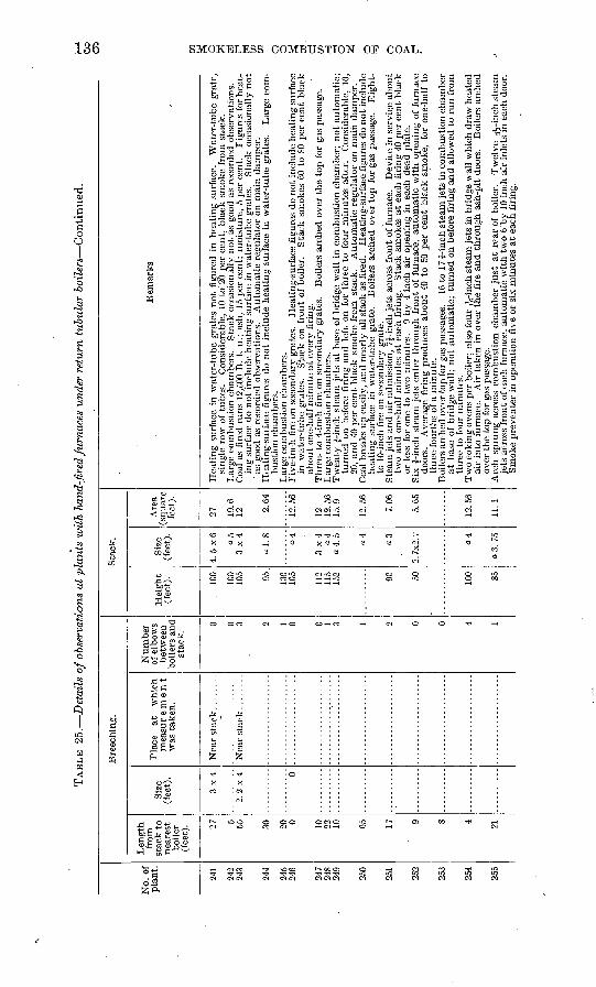
TAB
LE 25.
Det
ails
of o
bser
vati
ons
at p
lan
ts w
ith
hand
-fir
ed fu
rnac
es u
nder
ret
urn
tubu
lar
boil
ers
Con
tinu
ed.
No.
of
pla
nt.
241
242
243
244
245
246
247
248
249
250
251
252
253
254
255
Len
gth
fr
om
stac
k t
o
nea
rest
bo
iler
(f
eet)
. 27 55 30 20 0 10 22 10 Go 17 9 8 4 21
Size
(f
eet)
.
3x
4
2. 2
x 4 0
Bre
ech
ing
.
Pla
ce
at
whic
h
mea
sur
e m
e n
t
was
tak
en.
Num
ber
of
elb
ows
bet
wee
n
boil
ers
and
stac
k.
0 0 3 2 0 0 1 3 1 9 0 0
Hei
gh
t (f
eet)
. 100
100
105 95 130
105
112
115
152 90 50 100 So
Sta
ck.
Siz
e (f
eet)
.
4.5
x6
3x4
ol.
8 0.4
3x4 04
a4
«3
9
~X
9
7
Are
a (s
quar
e fe
et).
27 19.6
12 2.64
12.5
6
12 12.5
615
.9
12.5
6
7.06
Rem
arks
sing
le r
ow o
f tu
bes.
C
onsi
dera
ble,
10
to 2
0 pe
r ce
nt,
blac
k sm
oke
from
sta
ck.
ing
surf
ace
do n
ot i
nclu
de h
eati
ng s
urfa
ce i
n w
ater
-tub
e gr
ates
. S
tack
occ
asio
nally
not
' a
s go
od a
s re
cord
ed o
bser
vati
ons.
A
utom
atic
reg
ulat
or o
n m
ain
dam
per.
bust
ion
cham
bers
.
in w
ater
-tub
e gr
ates
. S
tack
on
fron
t of
boi
ler.
S
tack
sm
okes
60
to S
O pe
r ce
nt b
lack
ab
out
one-
half
min
ute
at e
very
fir
ing.
turn
ed o
n be
fore
fir
ing
and
left
on
for
thre
e to
fou
r m
inut
es a
fter
. C
onsi
dera
ble,
10,
20
, an
d 40
per
cen
t bl
ack
smok
e fr
om s
tack
. A
utom
atic
reg
ulat
or o
n m
ain
dam
per.
heat
ing
surf
ace
in w
ater
- tub
e gr
ate.
B
oile
rs a
rche
d ov
erto
p fo
r ga
s pa
ssag
e.
Eig
ht-
to 1
0-in
ch f
ire
on s
econ
dary
gra
te.
two
and
one-
half
min
utes
at
each
fir
ing.
S
tack
sm
okes
at
each
fir
ing
40 p
er c
ent
blac
k or
les
s fo
r on
e to
tw
o m
inut
es.
9 by
4 i
nch
air
open
ing
in e
ach
dead
pla
te.
door
s.
Ave
rage
fir
ing
prod
uces
abo
ut <
0 to
£0
per
cent
bla
ck s
mok
e, f
or o
ne-h
alf
to
thre
e-fo
urth
s of
a m
inut
e.
at b
ase
of b
ridg
e w
all;
not
auto
mat
ic;
turn
ed o
n be
fore
fir
ing
and
allo
wed
to
run
from
th
ree
to f
our
min
utes
.
air
into
fur
nace
. A
ir t
aken
in
over
the
fir
e an
d th
roug
h as
h-pi
t do
ors.
B
oile
rs a
rche
d ov
er t
he t
op f
or g
as p
assa
ge.
jets
acr
oss
fron
t of
eac
h fu
rnac
e, a
utom
atic
wit
h tw
o 6 '
by 1
0 in
ch a
ir i
nlet
s in
eac
h do
or.
Smok
e pr
even
ter
in o
pera
tion
fiv
e or
six
min
utes
at
each
fir
ing.
CO
O
i
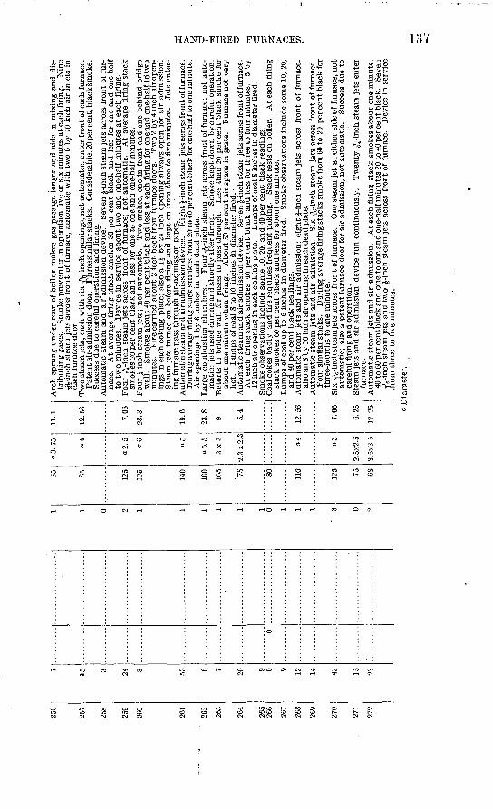
?57
?SS
259
>fiO
?B1
?,6?
?63
?64
?fi,5
266
?67
?fi,S
?(W
?70
?71
?7?
15 3
'24 3 53 6 7 20 9 0 9 12 14 42 23
6
0 9 1 1 1 1 1 1 0 1 1 1
3 0 9
* « 125
125
140
160
165 75 SO 110
125 75 OS
a 3.
75
<z4
"2.
5
06 o5
"5.
5
3x3
2.3
x2
.3
a4 o3
2.5x
2.5
3.5x
3.5
11.1
12.5
6
7.06
28. 3
19.6
23.8
9 5.4
12.5
6
7.06
6.25
12.2
5
Arc
h sp
rung
und
er r
ear
of b
oile
r m
akes
gas
pas
sage
lon
ger
and
aids
in
mix
ing
and
dis
tr
ibut
ing
gase
s.
Smok
e pr
even
ter
in o
pera
tion
fiv
e or
six
min
utes
at
each
fir
ing.
N
ine
3%-in
ch s
team
jet
s ac
ross
fro
nt o
f fu
rnac
e, a
utom
atic
wit
h tw
o 6
b}' 1
0 in
ch a
ir i
nlet
s in
ea
ch f
urna
ce d
oor.
Tw
o st
eam
jets
, ea
ch w
ith
six
y^-i
nch
open
ings
, not
aut
omat
ic,
ente
r fr
ont o
f eac
h fu
rnac
e.
Pat
ent a
ir-a
dmis
sion
doo
r. T
hre
e si
mil
ar s
tack
s.
Con
side
rabl
e, 2
0per
cen
t, bl
acks
mok
e.
Succ
ess
due
to c
aref
ul o
pera
tion
and
fir
ing.
Aut
omat
ic s
team
and
air
adm
issi
on d
evic
e.
Sev
en |-
inch
ste
am je
ts a
cros
s fr
ont
of f
ur
nace
. A
t av
erag
e fi
ring
sta
ck s
mok
es 3
0 pe
r ce
nt b
lack
and
les
s fo
r on
e an
d on
e-ha
lf
to t
wo
min
utes
. D
evic
e in
ser
vice
abo
ut t
wo
and
one-
half
min
utes
at
each
fir
ing.
Fou
r nV
inch
ste
am j
ets
acro
ss f
ront
of
furn
ace;
not
aut
omat
ic.
At
aver
age
firi
ng s
tack
sm
okes
20
per
cent
bla
ck a
nd l
ess
for
one
to o
ne a
nd o
ne-h
alf m
inut
es.
Fou
r J-
inch
ste
am j
ets;
not
aut
omat
ic.
Tw
o ar
ches
, on
e in
fro
nt a
nd o
ne b
ehin
d br
idge
w
all.
Smok
es a
bout
40
per
cent
blac
k an
d le
ss a
t ea
ch f
irin
g fo
r on
eand
one
-hal
f td
two
min
utes
. 1-
ire
carr
ied
abou
t 2
feet
bac
k fr
om f
urna
ce d
oors
. T
wo
2 by
4 in
ch a
ir o
pen:
- in
gs i
n ea
ch c
okin
g pl
ate;
als
o a
li b
y 24
inc
h op
enin
g al
way
s op
en f
or a
ir a
dmis
sion
. S
team
jet
s tu
rned
on
befo
re f
irin
g"an
d ke
pt o
n fr
om t
hree
to
five
min
utes
. Je
ts e
nter
in
g fu
rnac
e pa
ss t
hrou
gh a
ir-a
dmis
sion
pip
es.
Aut
omat
ic s
team
and
air
adm
issi
on d
evic
e.
Eig
ht J
-inc
h st
eam
jets
acr
oss
fron
t of f
urna
ce.
Dur
ing
aver
age
firi
ng s
tack
sm
okes
fro
m 2
0 to
40
per c
ent b
lack
for o
ne-h
alf t
o on
e m
inut
e.
Air
ope
ning
s 1
b.y
6 in
ches
in e
ach
dead
pla
te.
Lar
ge c
ombu
stio
n ch
ambe
rs.
Fou
r TV
,-inc
h st
eam
jet
s ac
ross
fro
nt o
f fu
rnac
e; n
ot a
uto
m
atic
; je
ts u
sed
duri
ng a
nd s
hort
ly a
fter
fir
ing.
Sm
oke
kept
dow
n by
care
ful
oper
atio
n.R
etor
ts i
n br
idge
wal
l fo
r ga
ses
to p
ass
thro
ugh.
L
ess
than
20
per
cent
bla
ck s
mok
e fo
r ab
out
one
min
ute
whe
n fi
ring
. A
bout
50
per
cent
air
spa
ce i
n gr
ate.
F
urna
ce n
ot v
ery
hot.
Lum
ps o
f coa
l 8
to 1
0 in
ches
in
diam
eter
fir
ed.
Aut
omat
ic s
team
and
air
adm
issi
on d
evic
e.
Seve
n J-
inch
ste
am je
ts a
cros
s fr
ont o
f fur
nace
. A
t ea
ch f
irin
g st
ack
smok
es 4
0 pe
r ce
nt b
lack
and
les
s fo
r th
ree
to f
our
min
utes
. 5
by
12 i
nch
air
open
ing
in e
ach
coki
ng p
late
. L
umps
of c
oal 8
inch
es in
dia
met
er f
ired
.Sm
oke
obse
rvat
ions
inc
lude
som
e 10
, 20,
and
40
per
cent
bla
ck r
eadi
ngs.
Coa
l cok
es b
adly
, an
d fi
re r
equi
res
freq
uent
pok
ing.
S
tack
res
ts o
n bo
iler.
At e
ach
firi
ng
stac
k sm
okes
60
per
cent
bla
ck a
nd l
ess
for
abou
t one
min
ute.
Lum
ps o
f coa
l up
to
6 in
ches
in d
iam
eter
fir
ed.
Smok
e ob
serv
atio
ns i
nclu
de s
ome
10,
20,
and
40 p
er c
ent
blac
k re
adin
gs.
Aut
omat
ic s
team
jet
s an
d ai
r ad
mis
sion
: ei
ght
J-in
ch s
team
jet
s ac
ross
fro
nt o
f fu
rnac
e,
also
an
8 by
20
inch
air
ope
ning
in e
ach
dead
pla
te.
Aut
omat
ic s
team
jet
s an
d ai
r ad
mis
sion
. Si
x -r
^-in
ch s
team
jet
s ac
ross
fro
nt o
f fu
rnac
e.
Fou
r si
mil
ar s
tack
s.
Dur
ing
aver
age
firi
ng s
tack
s sm
oke
from
60
to 2
0 pe
r ce
nt b
lack
for
thre
e-fo
urth
s to
one
min
ute.
"Si
x Tv
inch
ste
am je
ts a
cros
s fr
on
t of
fur
nace
. O
ne s
team
jet
at
eith
er s
ide
of f
urna
ce, n
ot
auto
mat
ic;
also
a p
aten
t fu
rnac
e do
or f
or a
ir a
dmis
sion
, no
t au
tom
atic
. Su
cces
s du
e to
ca
refu
l fi
ring
and
ope
rati
on.
Ste
am j
ets
and
air
adm
issi
on d
evic
e ru
n co
ntin
uous
ly.
Tw
enty
^-m
&h
stea
m j
ets
ente
r fu
rnac
e.A
utom
atic
ste
am je
ts a
nd a
ir a
dmis
sion
. A
t eac
h fi
ring
sta
ck s
mok
es a
bout
one
min
ute.
40
to
60 p
er c
ent b
lack
and
one
to o
ne a
nd o
ne-h
alf m
inut
es 2
0 to
40
per c
ent
blac
k.
Seve
n jV
inch
ste
am je
ts a
nd t
wo
J-in
ch s
team
jet
s ac
ross
fro
nt o
f fu
rnac
e.
Dev
ice
in s
ervi
ce
.from
thr
ee t
o fiv
e m
inut
es.
Dia
met
er.
CO
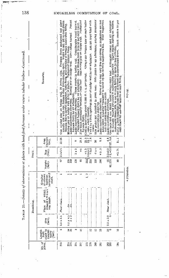
TAB
LE 25.
Det
ails
of
obse
rvat
ions
at
plan
ts w
ith
hand
-fir
ed fu
rnac
es u
nder
ret
urn
tubu
lar
boile
rs C
onti
nued.
No.
of
pla
nt.
273
274
275
276
277
27S 27
9
280
281
282
283
284
Len
gth
from
st
ack
to
near
est
boile
r (f
eet)
. 0 04 Orl 20 3 25 12 12 23 22 0 30
Siz
e (f
eet)
.
3.5
x 3
.5
3.5
x 4.
53x3
2.5
x 2
.8 0
Bre
ech
ing
.
Pla
ce
at
whi
ch
mea
sur
e m
e 11
1
was
tak
en.
Nea
r st
ack ..
....
..
....
.do..
....
....
....
...d
o..
....
....
..
Nea
r st
ack.
.......
Num
ber
of e
lbow
s be
twee
n bo
ilers
and
st
ack.
1 1 1 1 1
!, 2
1
. 1 1 2 -o 1
Hei
ght
(fee
t). 97 105
100
120 60
OO
K/
2M 235
110
190 65
85, 1
25 80
Sta
ck.
-
Siz
e (f
eet)
.
3.5x
3.5
3x3 «5
ao.3
5.5x
4.5
65x3
6x6
03
.5
2.2x
2.2
a 3,
a 3
.5
«3.
75
Are
a (s
quar
e fe
et).
12.2
5
9 19.6
22.3
24.7
7.
8
36 9.6 4.8
7.07
,9.6
11.1
Rem
arks.
\
One
mix
ing
pier
on
brid
ge w
all,
18 i
nche
s w
ide.
F
urna
ce d
oors
per
fora
ted
bu
t pl
ant
usua
lly
run
wit
h on
e fu
rnac
e do
or t
hree
-fou
rths
ope
n.
Wat
er i
n as
h p
it t
o co
ol g
rate
s.Su
cces
s du
e to
car
eful
ope
rati
on,
ligh
t fir
ing,
and
cra
ckin
g of
furn
ace
door
s af
ter
firi
ng.
Mix
ing
pier
on
brid
ge w
all
18 b
y 24
inc
hes.
P
erfo
rate
d fu
rnac
e do
ors.
Lar
ge c
ombu
stio
n ch
ambe
rs.
Mix
ing
pier
on
brid
ge w
all.
Som
e re
fuse
bur
ned.
P
aten
tfu
rnac
e do
ors
for
air
adm
issi
on.
Lar
ge c
ombu
stio
n ch
ambe
rs.
Thr
ee r
etor
ts i
n br
idge
wal
l. C
onsi
dera
ble
woo
d bu
rned
.Pe
rfor
ated
fur
nace
doo
rs f
or a
ir a
dmis
sion
. S
tack
sm
okes
fro
m 1
0 to
60
per
cent
bla
ck.
Fir
e th
ick,
pra
ctic
ally
ban
ked,
on
ligh
t lo
ad
One
mix
ing
pier
on
brid
ge w
all.
Per
fora
ted
furn
ace
door
s.1 C
oal a
s fi
red
runs
abo
ut 1
2,00
0 B
. t.
u. p
er p
ound
. A
lway
s on
e fu
rnac
e do
or o
n ea
ch b
oile
r1
open
whe
n ru
nnin
g.
Tw
o 4
by 6
inc
h op
enin
gs i
n re
ar o
f bri
dge
wal
l fo
r ai
r ad
mis
sion
. A
sh p
it k
ept f
illed
wit
hw
ater
.Si
de g
rate
s no
t in
clud
ed i
n gr
ate
area
. Si
de g
rate
s fo
r ai
r ad
mis
sion
; m
ixin
g st
ruct
ures
'in
com
bust
ion
cham
ber.
Lar
ge c
ombu
stio
n ch
ambe
rs.
Som
e of
the
coa
l ve
ry f
ine
and
cake
s, s
o m
agaz
ines
are
not
kept
fill
ed;
prob
ably
nec
essa
ry t
o br
eak
up f
ire
to k
eep
mag
azin
es f
ull.
Wit
h m
agaz
ines
not
full
cons
ider
able
air
ent
ers.
Lar
ge c
ombu
stio
n ch
ambe
rs.
One
lar
ge a
nd o
ne s
mal
l bo
iler
alw
ays
carr
y lo
ad.
Aut
omat
ic s
team
and
air
adm
issi
onin
fur
nace
; m
ixin
g st
ruct
ure
in c
ombu
stio
n ch
ambe
r.
Thr
ee s
tack
s re
stin
g on
boi
lers
.A
utom
atic
ste
am je
ts,
in u
se a
t ea
ch f
irin
g fo
r th
ree
to f
our
min
utes
. F
orty
-Jj.-
inch
ope
ning
s ac
ross
fro
nt o
f fur
nace
for s
uper
heat
ed s
team
. S
tack
sm
okes
10
per
cent
bla
ck f
or o
ne-h
alf m
inut
e at
eac
h fi
ring
.
CO
C
O
a. D
iam
eter
.b
Ova
l.
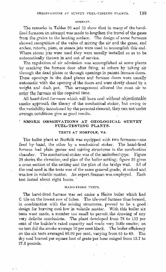
OBSERVATIONS AT SURVEY FUEL-TESTING PLANTS. 139
SUMMARY.
The remarks in Tables 20 and 25 show that in many of the hand- fired furnaces an attempt was -made to lengthen the travel of the gases from the grates to the heating surface. -The design of some furnaces showed recognition of the value of mixing the air and the gases, and arches, retorts, piers, or steam jets were used to accomplish this end. Where steam jets were used they were usually installed so as to be automatically thrown in and out of service.
The regulation of air admission was accomplished at some plants by cracking the furnace door after firing, at others by taking air through the dead plates or through openings in patent furnace doors. These openings in the dead plates and furnace doors were usually automatic with the opening of the doors and were slowly closed by a weight and clash pot. This arrangement allowed the most air to enter the furnace at the required time.
All hand-fired furnaces which will burn coal without objectionable smoke approach the theory of the mechanical stoker, but owing to the variability introduced by the personal element, they can not under average conditions give as good results.
' SMOKE OBSERVATIONS AT GEOLOGICAL SURVEY FUEL-TESTING PLANTS.
TESTS AT NORFOLK, VA.
The boiler plant at Norfolk was equipped with two furnaces one fired by-hand, the other by a mechanical stoker. The hand-fired furnace had plain grates and mixing structures in the combustion chamber. The mechanical stoker was of the underfeed type. Figure 38 shows the elevation,and plan of the boiler setting; figure 39 gives a cross section of the setting and the plan of the bridge wall. All of the coal used in the tests was of the same general grade; it coked and was low in volatile matter. An expert fireman was employed. Each test lasted about eight hours.
HAND-FIRED TESTS.
The hand-fired furnace was set under a Heine boiler which had C tile on the lowest row of tubes. The tile-roof furnace thus formed, in combination with the mixing structures, proved to be a good design for burning coal low in volatile matter. With this boiler six tests were made, a number too small to permit, the chawing of any very definite conclusions. The plant developed from 78 to 155 per cent of the builder's rated capacity and made very little smoke; on no test did the smoke average 10 per cent black. The boiler efficiency on the six tests averaged 66.90 per cent, varying from 65 to 69. The dry coal burned per square foot of grate per hour ranged from 13.7 to 27.6 pounds.
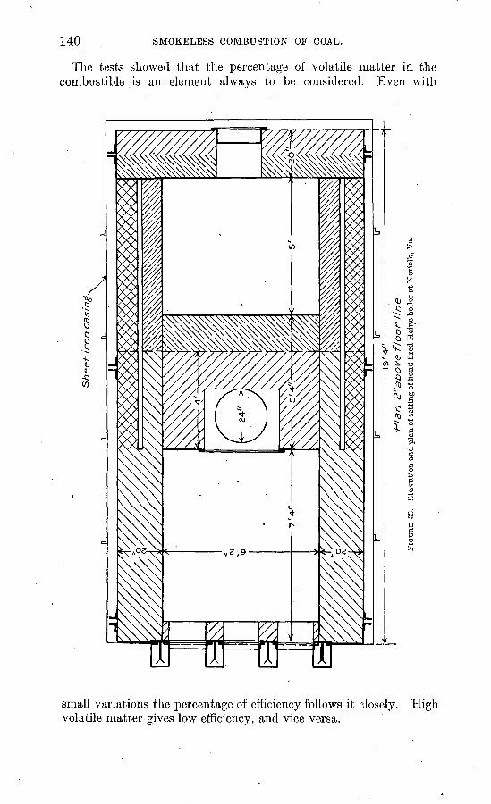
140 SMOKELESS COMBUSTION OF COAL.
The tests showed that the percentage of volatile matter in the combustible is an element always to be considered. Even with
small variations the percentage of efficiency follows it closely, volatile matter gives low efficiency, and vice versa.
High
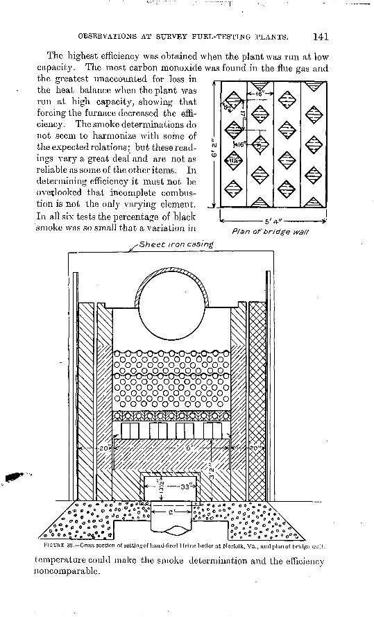
OBSERVATIONS AT SURVEY FUEL-TESTING PLANTS. 141
The highest efficiency was obtained when the plant was run at capacity. The most carbon monoxide was found in the flue gas the greatest unaccounted for loss in the heat balance when the plant was run at high capacity, showing that forcing the furnace decreased the effi ciency. The smoke determinations do not seem to harmonize with some of the expected relations; but these read ings va,ry a great deal and are not as reliable as some of the other items. In determining efficiency it must not be overlooked that incomplete combus tion is not the only varying element. In all six tests the percentage of black smoke was so small that a variation in
low and
LPlan of bridge waf/
-Sheet iron casing
FIGURE 39. Cross section of settlngof hand-fired Heine boiler at Norfolk, Va., and plan of bridge wall.
temperature could make the smoke determination and the efficiency noncomparable.
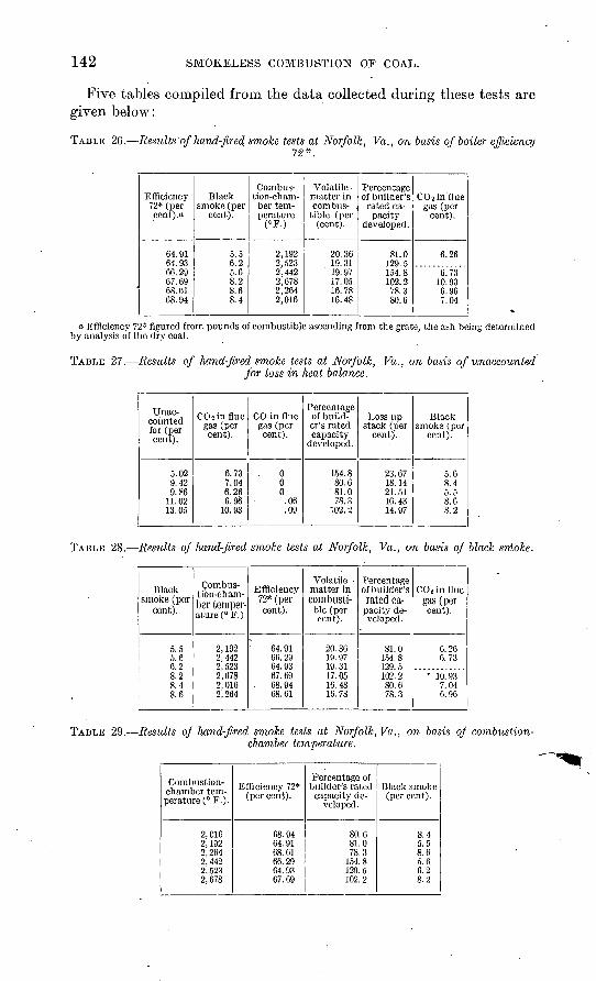
142 SMOKELESS COMBUSTION OF COAL.
Five tables compiled from the data collected during these tests are given below:
TABLE 26. Results of hand-fired smoke tests at Norfolk, Va., on basis of boiler efficiency72*.
Efficiency72* (percent). a
64.9164.9366.2967.6968. 6168. 94
Blacksmoke (per
cent).
5.56.25.68.28.68.4
Combustion-chamber temperature
(°F.).
2,1922,5232,4422,6782,2642,016
Volatile matter incombus
tible (per(cent).
20.3619.3119.9717. 0516.7816.48
Percentageof builder'srated capacity
developed.
81.0129.5154. 8102.278.3
80.6
COsin.fluegas (per
cent).
6.26
6.7310.936.967.04
a. Efficiency 72* figured from pounds of combustible ascending from the grate, the ash being determined by analysis of the dry coal.
TABLE 27. Results of hand-fired smoke tests, at Norfolk, Va., on basis of unaccountedfor loss in heat balance.
Unac counted for (per cent).
5.029.429.86
11.0213.05
CO 2 in flue gas (per cent).
6.737.046.266.96
10.93
CO in flue gas (per cent).
000
.06
.09
Percentage of build er's rated capacity
developed.
154.880.681.078.3
102.2
Loss up stack (per
cent).
23.6718.1421.5116. 4314.97
Black smoke (per
cent).
5.68.45.58.68.2
TABLE 28. Results of hand-fired smoke tests at Norfolk, Va., on basis of black smoke.
Black smoke (per
cent).
5.5 5.6 6.28.2 8.4 8.6
Combus tion-cham ber temper ature (°F.).
2,192 2,442 2,5232,678 2,016 2,264
Efficiency 72* (per cent).
64. 91 66. 29 64. 9367.69
- 68. 94 C8.61
Volatile matter in combusti ble (per cent).
20.36 19.97 19.3117.05 16.48 16.78
Percentage of builder's rated ca
pacity de veloped.
81.0 154.8 129. 5102. 2 80.6 78.3
CO 2 in flue gas (percent).
6.26 6.73
- 10.93 7.04 0.96
TABLE 29.- -Results of hand-fired smoke tests at Norfolk,Va., on basis of combustion- chamber temperature.
Combustion- chamber tem perature (° F.).
2,0162,1922,2642,4422,5232,678
Efficiency 72* (per cent).
68. 9464.9168.6166.2964.9367.69
Percentage of builder's rated
capacity de veloped.
80.681.078.3
154. 8129.5102.2
Black smoke (per cent).
8.45.58.65.60.28.2
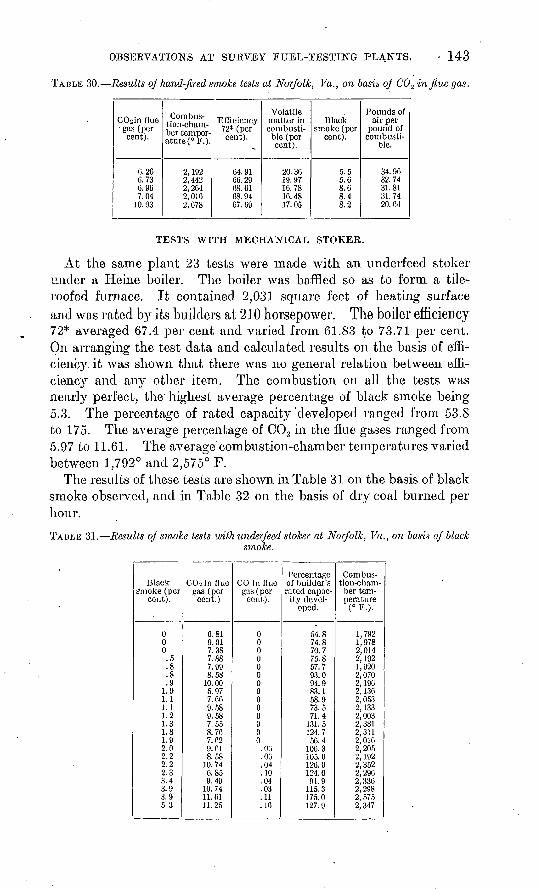
OBSERVATIONS AT SURVEY FUEL-TESTING PLANTS. 143
TABLE 30. Results of hand-fired smoke tests at Norfolk, Va., on basis of C02 in flue gas.
C02 in fine gas (per
cent).
6.266.736.967.04
10.93
Combus tion-cham ber temper ature (° P.).
2,1922,4422,2642, 0162,678
Efficiency 72* (per cent).
64.9166.2968.6168.9467.69
Volatile matter in combusti ble (per cent).
20.3619. 9716.7816. 4817.05
Black smoke (per
cent).
5.55.68.68.48.2
Pounds of air per
pound of combusti
ble.
34. 9632.7431.8131.7420. 64
TESTS WITH MECHANICAL STOKER.
At the same plant 23 tests were made with an underfeed stoker under a Heine boiler. The boiler was baffled so as to form a tile- roofed furnace. It contained 2,031 square feet of heating surface and was rated by its builders at 210 horsepower. The boiler efficiency 72* averaged 67.4 per cent and varied from 61.83 to 73.71 per cent. On arranging the test data and calculated results on the basis of effi ciency, it was shown that there was no general relation between effi ciency and any other item. The combustion on all the tests was nearly perfect, the highest average percentage of black smoke being 5.3. The percentage of rated capacity'developed ranged from 53.8 to 175. The average percentage of C0 2 in the flue gases ranged from 5.97 to 11.61. The average combustion-chamber temperatures varied between 1,792° and 2,575° F.
The results of these tests are shown in Table 31 on the basis of black smoke observed, and in Table 32 on the basis of dry coal burned per hour.
TABLE 31. Results of smoke tests withunderfeed stoker at Norfolk, Va., on basis of "blacksmoke.
Black Smoke (per
cent).
000.5.8.8.9
1.01.11.11.21.31.81.92.02.22.22.33.43.93.95.3
CO 2 in flue gas (pei- cent.)
6.819.017.387.887.99S.58
10.005.977.609.589.587.558.767.629.618.58
10.746.859.49
10.7411.6111.25
CO in flue gas (per cent).
00000000000000
.03
.00
.04
.10
.04
.03
.11
.16
Percentage of builder's rated capac ity devel
oped.
54.874.870.775.857.793.094.983.158.973.571.4
131.5124.756.4
106.3105.0120. 0124.091.9
115.3175.0127.9
Combus tion-cham ber tem perature
(° F.).
1,7921,9782,0.142,1921,9202,0702,1902, 1362,0532,1332,0032,3812,3112,0162,2052,1922,3522,2902,3362,2982, 5752,347
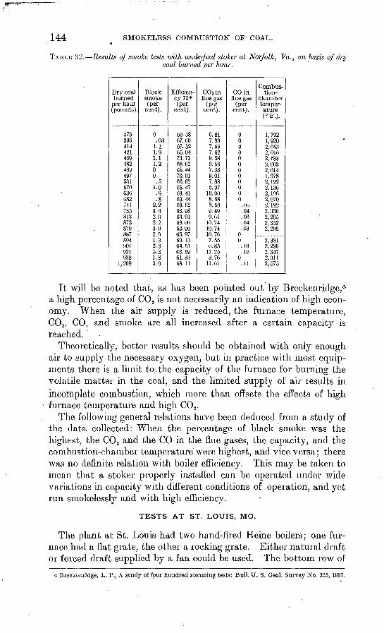
144 SMOKELESS COMBUSTION OF COAL.
TABLE 32. Results of smoke tests with underjeed stoker at Norfolk, Va., on basis of drycoal burned per hour.
Dry coalburned
per hour (pounds).
376 396414421469482489497 ,531570636682711735813872879887894901921938
1, 209
Blacksmoke(per
cent).
0 .08
1.11.91.11.200.5
1.0.9.8
2.23.42.02.23.92.91.32.35.31.83.9
Efficiency 72*(per
cent).
69.58 67.0066.5265. 0473.7168. 6268.4470.0166.6268.4769. 4163.4469. 6268.9863.9168.0063.9065.9769. 1364.51CS. 5961. 8368. 11
C02 influe gas
(Percent).
6.81 7.997.667.629.589.587.389.017.885.97
10.008.588.589.499.61
10.7410.7410. 767.556.85
11. 258.76
11.61
CO influe gas
(per cent).
0 00000000000
.06
.04
.06
.04
.0300.10.16
0.11
Combustion-
chain hertemper ature
1,792 1,9202,0532,0162,1332,0032,0141,9782,1922, 1362, 1962,0702,1922, 3362,2052,3522,298
2,3812, 2962,3472,3112,575
It will be noted that, as has been pointed out by Breckenridge,a a high percentage of C02 is not necessarily an indication of high econ omy. When the air supply is reduced, the furnace temperature, C02 , CO, and smoke are all increased after a certain capacity is reached.
Theoretically, better results should be obtained with only enough air to supply the necessary oxygen, but in practice with most equip ments there is a limit to., the capacity of the furnace for burning the volatile matter in the coal, and the limited supply of air results in incomplete combustion, which more than offsets the effects of high furnace temperature and high CO 2 .
The following general relations have been deduced from a study of the data collected: When the percentage of black smoke was the highest, the C0 2 and the CO in the flue gases, the capacity, and the combustion-chamber temperature were highest, and vice versa; there was no definite relation with boiler efficiency. This may be taken to mean that a stoker properly installed can be operated under wide variations in capacity with different conditions of operation, and yet run smokeless!}7" and with high efficiency.
TESTS AT ST. LOUIS, MO.
The plant at St. Louis had two hand-fired Heine boilers; one fur nace had a flat grate, the other a rocking grate. Either natural draft or forced draft supplied by a fan could be used. The bottom row of
a Breckenridge, L. P., A study of four hundred steaming tests: Bull. U. S. Geol. Survey No. 325, 1907.
OBSERVATIONS AT SURVEY FUEL-TESTING PLANTS. 145
water tubes in each boiler was incased in tile, forming tile-roof fur naces. In most of the tests these furnaces contained some sort of structure to mix the air and the gases from the fire, and thus hasten combustion. An expert fireman working under the direction of a competent engineer was employed in all tests.
The following tables and deductions are compiled from tests made at this plant and supplement the observations in the field and at Norfolk, as they throw light on several points which have hereto fore been little considered or at least not fully determined. All the tables have a bearing on the problem of smoke prevention and they are presented because they may be of assistance in its solution.
Table 33 shows the results of six tests made to determine the best method of hand firing a high-volatile Illinois coal, nut size, using natural draft. The proximate analysis of the "coal as fired showed the following: Volatile matter, about 36 per cent; ash, about 10 per cent; moisture, about 13 per cent; British thermal units average, 10,948.
Four different methods of firing were used ribbon (firing alter nately in'narrow strips across the full length of the grate), coking,
. alternate, and spreading. In every test a reasonably thin fire was carried, from 2 to 3 inches of incandescent fuel above the clinker. Wheno firing by the spreading method'three shovelfuls of coal were thrown on the back of the grate and two on the front. When firing by the ribbon method the fire doors were kept cracked.
The average of tests 500 and 504 was taken as representative of the alternate method of firing. On test 500 the furnace doors were closed tightly after each firing; on test 504 they were kept cracked. This cracking of the furnace doors, while it caused a slight reduction in smoke compared with test 500, proved to be wasteful because the combustion space was not constructed so as to make the excess air of value in hastening combustion. A compromise method, cracking the doors for a short time after firing and then closing them, ought to give as good if not better results for alternate firing than those shown in the table.
The ribbon method of firing, where the coal was fired most fre quently with the smallest amount per firing, gave the highest effi ciency and practically no smoke. The usual spreading method of .firing gave the lowest efficiency and caused the most smoke. The results with the. alternate and the coking methods showed that one was about as good as the other.
74897 Bull. 373 09 10
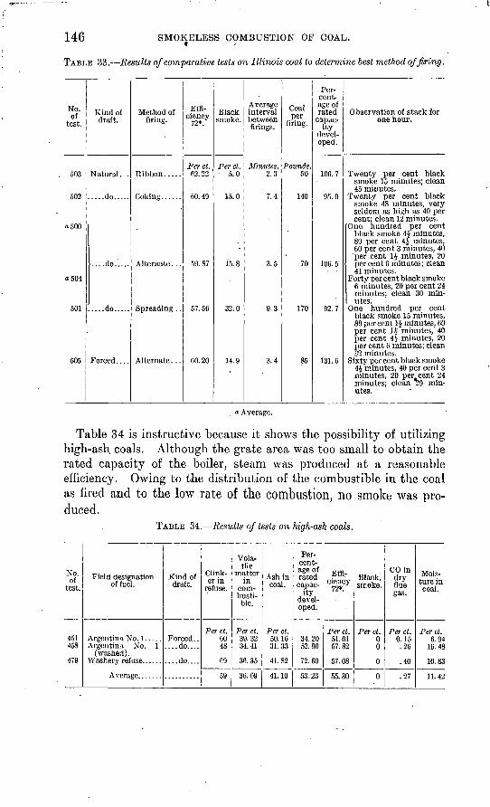
146 SMOKELESS COMBUSTION OF COAL.
TABLE 33. Results of comparative tests on Illinois coal to determine best method of firing.
No. of
test.
503
502
0500
"504
501
505
Kind of draft.
Natural . . .
.....do.....
....do.....
.....do.....
Forced....
Method of firing.
Ribbon.....
Coking......
Alternate. ..
Spreading . .
Alternate . . .
Effi ciency
72*.
Per ct.62.22
.60.49
59.87
57.56
60.20
Black smoke.
Perct.5.0
15.0
c
15.8
32.0
14.9
Average interval between firings.
Minutes.2.3
7.4
3.5
9.3
3.4
Coal per
firing.
Pounds.50
140
70
170
85
Percentage of rated
capac ity
developed.
100. 7
95.0
106.5
92.7
131.6
Observation of stack for one hour.
Twenty per cent blacksmoke 15 minutes; clean45 minutes.
Twenty per cent blacksmoke 48 minutes, veryseldom as high as 40 percent; clean 12 minutes.
One hundred per centblack smoke 4| minutes,80 per cent 4J minutes,60 per cent 3 minutes, 40
'per cent 1J minutes, 20percent G minutes; clean41 minutes.
Forty per cent black smoke 6 minutes, 20 per cent 24minutes; clean 30 minutes.
One hundred per centblack smoke 15 minutes,80 per cent 1£ minutes, 60per cent 1$ minutes, 40per cent 4> minutes, 20per cent 6 minutes; clean32 minutes.
Sixty per cent black smoke4j minutes, 40 per cent 3minutes, 20 per cent 24 minutes; clean 29 minutes.
« Average.
Table 34 is instructive because it shows the possibility of utilizing high-ash coals. Although the grate area was too small to obtain the rated capacity of the boiler, steam was produced at a reasonable efficiency. Owing to the distribution of the combustible in the coal as fired and to the low rate of the combustion, no smoke was pro duced.
TABLE 34. Results of tests on high-ash coals.
No. of
test.
451458
47M
Field designation of fuel.
Argentina No. 1.....Argentina . No. 1
(washed).
Kind of draft.
Forced. .....do....
....do....
Clink er in
refuse.
Perct.6048
69
59
Vola tile
matter in
com-busti-
Per ct.39.3234.41
36.35
36.69
Ash in coal.
Perct.50.1631.33
41.82
41.10
Per cent age of rated capac
ity developed.
34.2052.90
72.60
53.23
Effi ciency
72*.
Perct.51.0157.82
57.08
55.30
Black, smoke.
Perct.00
0
0
CO indry flue
Perct.0.15.26
.40
.27
Mois ture in coal.
Perct.6.94
16.48
10.83
11 42
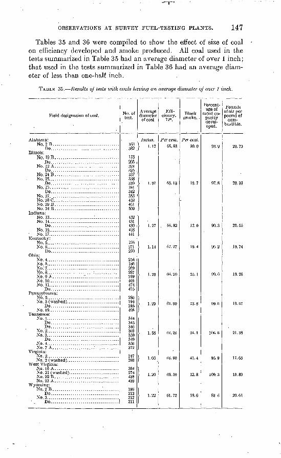
OBSERVATIONS AT SURVEY FUEL-TESTING PLANTS. 147
Tables 35 and 36 were compiled to show the effect of size of coal on efficiency developed and smoke produced. All coal used in the tests summarized in Table 35 had an average diameter of over 1 inch; that used in the tests summarized in Table 36 had an average diam eter of less than one-half inch.
TABLE 35. Results oj tests ivith coals having an average diameter of over 1 inch.
Field designation of coal.
Alabama': No.2B. ................................
Do..................................Illinois:
No 19 BDo..................................
No. 22 A ................................Do..................................
No. 24B. ...............................No. 25...................................
Do..................................No. 26......... .........................
Do..................................No. 27. .................................No.28C.................................No. 29B. ...............................N0.34B................................
Indiana: No. 13.. ....................:............No. 14...... .............................
Do..................................No. 15...................................No. 17...................................
Kentucky: No. 5.... ................................No. 6........... .........................
Do..................................Ohio:
No. 4. ...................................No. 5.....................................No.'7..... ...............................No. 8.. .....................:............No. 9 A................'. ................No. 10...... .............................No. 11..... ..............................
Do..................................Pennsylvania:
No. 5....................................
Do..................................No. 19...................................
Tennessee: No. 1... .................................
Do..................................Do..................................
No. 2..... ...............................No. 3....................................
Do..................................No. 4....................................No. 7 A....................:............
Virginia: No. 2....................................
West Virginia: No. 16 A .................................No. 21 (washed).........................No.22B. ...............................No. 23 A................................
Wyoming: No.2B. ................................
Do..................................No. 3................. ...................
Do..................................
No. of test.
3S3.382
175205324325337338339341342353452461509
432431430428441
276271270
254186269287249469474475
286194195498
344345
369350349356372
247260
274438439
196213212211
Average diameter
of coal
Inches. \ 1.12
I 1.97
1.27
|
I 1.29
1
1. 58
j- 1.03
1 1.20
1
1 1.22
J
Effi ciency.
72*.
Per cent.65. 83
65.13
66. 82
67.27
60. 20
66. 26
66. 90
68.59
61.72
Black smoke. .
Per cent.30.0
19.7
12.0
19.4
23.8
12.8
15. 0
Percent age of
rated ca pacity devel oped.
97.8
90.3
96.2
99.6
106. 6
95.9
83 6
Pounds of air per pound of
com bustible.
23.73
20.33
20.55
19.74
19.26
19. 67
21.38
17. 63
19.89
20.61
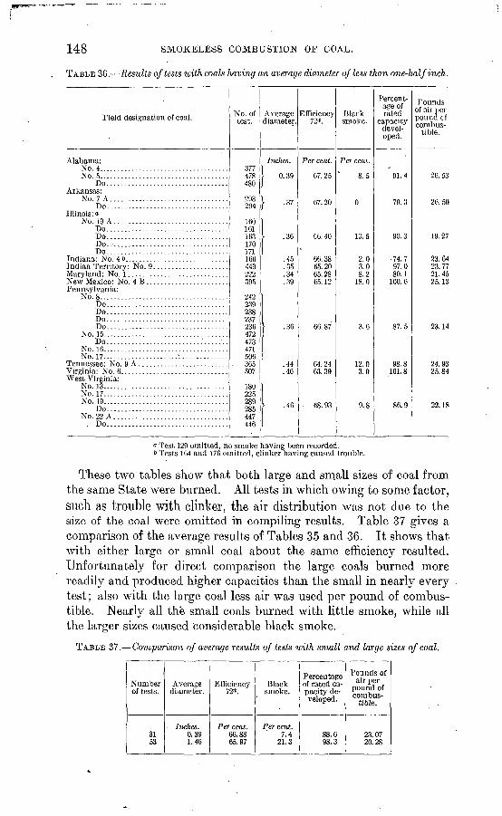
148 SMOKELESS COMBUSTION OF COAL.
TABLE 36. Results of tests loith coals having an average diameter of less than one-half inch.
Field designation of coal.
Alabama: No. 4....................................No. 5-........-.....-.......-.-.-....-.-.
Do..................................Arkansas:
No. 7 A.................................Do..................................
Illinois: a No. 19 A................................
Do..................................Do..................................Do..................................Do...................................
New Mexico* No 4 BPennsylvania:
No. 8....................................Do..................................Do..................................Do..................................Do..................................
No. 15...................................DO..........................:.......
No. 10...................................No. 17.. ..................."..............
West Virginia: No. 13. ..................................No. 17...................................No 19
Do..................................No. 22 A ................................
. Do..................................
No. of test.
377478480
093
294
160161163170171166449222OQC
242239238237236XT)473471506365507
180225289285447446
Average diameter.
Inches.
1 0.39
\ 37/ ' 37
.36
.45
.35
.34"}Q
> .36
.44
.46
.46
Efficiency72*.
Per cent.
07.25
67.20
C6.40 «
66.3865.2065. 28f><; 19
66.87
64. 2463.39
- 68. 93
Black smoke.
Per cent.
8.5
0
13.5
2.0 < n8.2
18.0
3.6
3.0
9.8
Percent age of rated
capacity devel oped.
91.4
79.3
90.3
74.797.080.1
100.6
87.5
98.8101.8
86.9
Pounds of air per pound cf combus
tible.
26.53
26. 50
19.27
23.6423.7721.4525.13
23.14
24.9325.84
22.18
i Test 129 omitted, no smoke having been recorded.b Tests.164 and 176 omitted, clinker having caused trouble.
These two tables show that both large and small sizes of coal from the same State were burned. All tests in which owing to some factor, such as trouble with clinker, the air distribution was not due to the size of the coal were omitted in compiling results. Table 37 gives a comparison of the average results of Tables 35 and 36. It shows that with either large or small coal about the same efficiency resulted. Unfortunately for direct comparison the large coals burned more readily and.produced higher capacities than the small in nearly every test; also with the large coal less air was used per pound of combus tible. Nearly all the small coals burned with little smoke, while all the larger sizes caused considerable black smoke.
TABLE 37. Comparison of average results of tests with small and large sizes of coal.
Number of tests.
3153
Average diameter.
Inches.0.391.46
Efficiency 72*.
Per cent.66.8865.97
Black smoke.
Per cent.7.4
21.3
Percentage of rated ca pacity de veloped.
88.698.3
Pounds of air per
pound of combus
tible.
23.0720.28
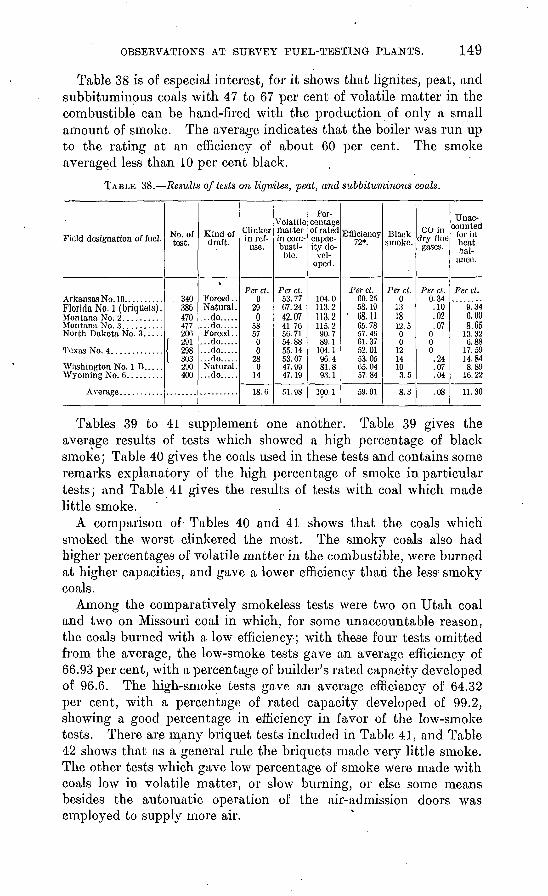
OBSERVATIONS AT SURVEY FUEL-TESTING PLANTS. 149
Table 38 is of especial interest, for it shows that lignites, peat, and subbituminous coals with 47 to 67 per cent of volatile matter in the combustible can be hand-fired with the production of only a small amount of smoke. The average indicates that the boiler was run up to the rating at an efficiency of about 60 per cent. The smoke averaged less than 10 per cent black.
TABLE 38. Results of tests on lignites, peat, and subbituminous coals.
Field designation of fuel.
Florida No. 1 (briquets).
North Dakota No. 3.....
Washington No. IB.....
No. of test.
, 340386 470477200
I 291{ 298I 303
290 400
Kind of draft.
Forced .Natural ...do.......do....Forced .
...do....
...do....
...do.... Natural ...do....
Clinker i n ref
use.
Per ct. 0
29 0
5857
00
28 0
14
18.0
Volatile rhatter in com busti
ble.
Per ct. 53.77C7.24 42.0741.7050.71
55.1453.07 47.99 47.19
51. 98
Per centage of rated capac ity de
vel oped.
104. 0113. 2 113.2
90.7 89.1
104.190.4 81.8 93.1
100.1
Efficiency 72*.
Per ct. CO. 2558.19
1 68.11G5. 7857. 40 61.3752. 0153.05 65.04 57.84
59.91
Black smoke.
Per ct. 0
13 1810 C
0 0
1214 10 3.5
8.3
COin dry flue gases.
Per ct. 0.34.10 .02.07
0 00
.24
.07
.04
.08
Unac counted
for in heat bal
ance.
Per ct.
9.34 0.008.65
13.326.88
17.5914. 84 8.89
16.22
11. 30
Tables 39 to 41 supplement one another. Table 39 gives the average results of tests which showed a high percentage of black smoke; Table 40 gives the coals used in these tests and contains some remarks explanatory of the high percentage of smoke in particular tests; and Table 41 gives the results of tests with coal which made little smoke.
A comparison of Tables 40 and 41 shows that the coals which smoked the worst clinkered the most. The smoky coals also had higher percentages of volatile matter in the combustible, were burned at higher capacities, and gave a lower efficiency than the less' smoky coals.
Among the comparatively smokeless tests were two on Utah coal and two on Missouri coal in which, for some unaccountable reason, the coals burned with a low efficiency; with these four tests omitted from the average, the low-smoke tests gave an average efficiency of 66.93 per cent, with a percentage of builder's rated capacity developed of 96.6. The high-smoke tests gave an average efficiency of 64.32 per cent, with a percentage of rated capacity developed of 99.2, showing a good percentage in efficiency in favor of the low-smoke tests. There are many briquet tests included in Table 41, and Table 42 shows that as a general rule the briquets made very little smoke. The other tests which gave low percentage of smoke were made with coals low in volatile matter, or slow burning, or else some means besides the automatic operation of the air-admission doors was employed to supply more air.
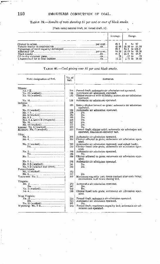
150 SMOKELESS COMBUSTION OP COAL.
TABLE 39. Results of tests showing 35 per cent or over of black smoke.
[Tests using natural draft, 34; forced draft, 5.]- ^
.....................do....
.....................do....
Average.
49.942.8899.204. 3241.8
.28. 12.55
Range.
0 to '6736.38 to 51.5884.4 to 129.956.04 to 09.3635.0 to 54.8
. 07 to . 735.71 to 19.03
TABLE 40. Coal giving over 35 per cent black smoke.
Field designation of fuel.
Illinois: No.7E. ...........................
NO. 16........:.. ...................Indiana:
No. 5.. .............................
No. 7 A............................
No.9 A............................
No. 10..............................
Ohio: No. 3.......... ........-.--..-. -----No. 4.... ...........................
Do.............................
No. 5...... .........................Do.............................
No. 7..... ...........................
No. 9 A. ...........................
Pennsylvania:
No. 6... ............................
Virginia: No. 2..............................
Do.............................
No. 4.......... .....................
West Virginia: No. 15..... .........................
Do.............................
Wyoming: No. 2 B. ....................
No. of test.
516 144 152
150
153
159 158 184 168 334 107 177 323 332
203. 202
220 219
190 186 269
241 243
195 217 367
251 247 200 240
216 215 267 213
Remarks.
Forced draft; automatic air admission not operated. Automatic air admission operated. Clinker removed with difficulty; automatic air admission
operated. Automatic air admission operated.
Heavy clinker formed on grate; automatic air admission operated.
Automatic air admission operated. Do. Do. Do. Do. Do. Do. Do.
Forced draft; clinker solid; automatic air admission not operated; maximum-capacity test.
Automatic air admission operated. Clinker adhered to grate; automatic air admission oper
ated. Automatic air admission operated; coal caked badly. Clinker fused into grate; automatic air admission oper
ated. Automatic air admission operated.
Do. Clinker adhered to grate; automatic air admission oper
ated.Automatic air admission operated.
Do. Do.
Do. Maximum-capacity test; doors cracked after each firing;
combustion wall down during test.
Automatic air admission operated. Do. Do.
Clinker fused into grate; automatic air admission oper ated.
Forced draft; automatic air admission operated. Automatic air admission operated.
Do. Forced draft; maximum-capacity test; automatic air ad
mission not operated.
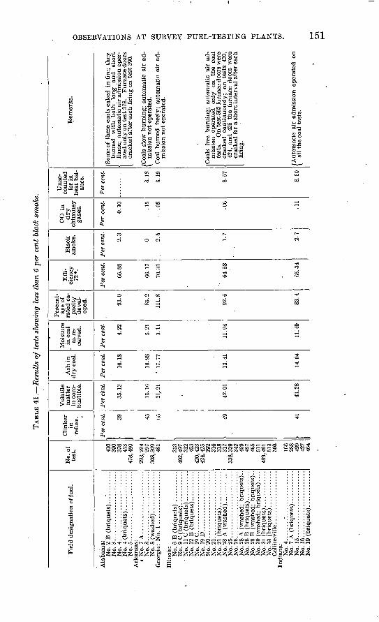
TAB
LE 4
1.
Res
ults
of
test
s sh
owin
g le
ss t
han
6 pe
r ce
nt b
lack
sm
oke.
Fie
ld d
esig
nati
on o
f fue
l.
Ala
bam
a:
No.
2 B
(b
riq
uets
)...
'...
....
..N
o. 3
.. .............
....
....
..N
o. 4
..........................
Ark
ansa
s:
« N
o. 7
A............
....
....
..N
o. 8
.........................
Illi
nois
: N
o. 6
B (
bri
qu
ets)
...........
No.
9C
(bri
quet
s). ...........
No.
19 C
....
....
......
....
....
No.
19
D. .
....
....
............
No.
20
........................
No.
21... .....................
No.
23
A (
wash
ed).
...........
No.
25
....
....
....
............
No.
26
....
....
....
............
No.
28
A (
was
hed;
bri
quet
s)..
No.
28
B (
bri
qu
ets
)...-.
.-..-.
No.
29
B (
was
hed;
bri
qu
ets)
..
No.
30
(was
hed;
bri
qu
ets)
. ...
No.
33
(bri
quet
s) ...
....
....
..
Ind
ian
a:
No.
4..............
....
....
....
No.
15........................
No.
16........................
No.
19
(bri
quet
s). ............
No.
of
test
. 410
390
378
413
293,
294
297
308,
309
481
313
492,
497 312
463
424,
425
292
316
318
317
338,
339
342
459
457
465
511
489,
491 513
=;03
166
288
429
427
464
Cli
nker
in
re
fuse
.
Per
cen
t. 39
1 «
165 49
1 V
olat
ile
mat
ter
in c
om
bust
ible
.
Per
cen
t.
35.1
3
21.2
1
42.0
1
43.2
8
Ash
in
dry
coa
l.
Per
cen
t.
16.1
8
i fl
no
14.0
4
Moi
stur
e in
coa
l as
re
ce
ived
.
Per
cen
t.
4.22
5.21
3.11
11.9
4
11.4
9
Per
cent
ag
e of
ra
ted
ca
p
acit
y
deve
l
oped
.
93.0
85. 2
111.
8
92. G
83.4
Eff
i
cien
cy
72*.
Per
cen
t.
66.8
8
66.1
7
64.5
8
65.3
4
Bla
ck
smok
e.
Per
cen
t.
2.3
0 2.5
1.7
2.7
CO
in
dry
ch
imn
ey
gase
s.
Per
cen
t.
0.10 .1
5
.0
8
.06
.11
Una
c
coun
ted
for
in
hea
t ba
l
ance
.
Per
cen
t.
S.18
6.19
S.57
8. S
O
Rem
arks
.
Som
e of
the
se c
oals
cak
ed i
n f
ire;
they
burn
ed
wit
h b
oth
lo
ng
and
sh
ort
ated
onl
y on
tes
t 37
8.
Fu
rnac
e do
ors
Coa
l bu
rned
fre
ely;
au
tom
atic
air
ad
mis
sion
no
t op
erat
ed.
Coa
ls f
ree
burn
ing;
au
tom
atic
air
ad-
test
s.
On
test
503
fur
nace
doo
rs w
ere
1 cr
acke
d co
ntin
uous
ly;
on t
ests
420
,42
4, a
nd
425
th
e fu
rnac
e do
ors
wer
ecr
acke
d fo
r a
sho
rt i
nter
val
afte
r ea
chfi
ring
.
1-3
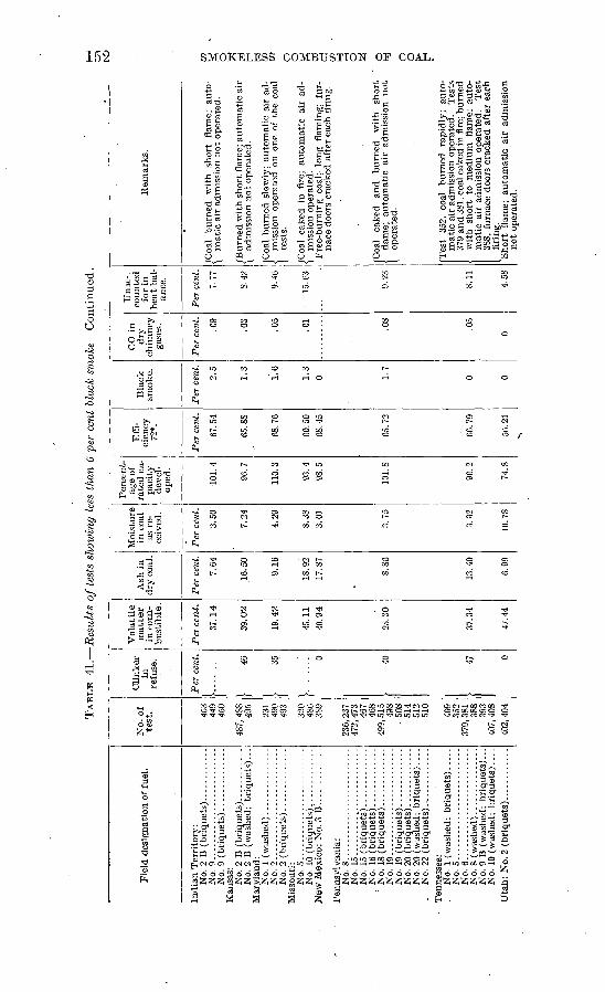
TAB
LE 4
1.
Res
ult
s o
f te
sts
show
ing
less
tha
n 6
per
cent
bla
ck s
moke C
onti
nued
.
Fie
ld d
esig
nati
on o
f fu
el.
Ind
ian
Ter
rito
ry:
No.
9..............
..
.
Kan
sas:
N
o. 2
B (
bri
quet
s).. . .........
No.
2 B
(w
ashe
d; b
riquet
s)...
Mar
ylan
d:
No.
2. .
............
............
Mis
sour
i:
No.
5.. ...
... ..
....
...........
No.
10
(bri
quet
s) .............
New
Mex
ico;
No.
3 B
'.. ...........
Pen
nsyl
vani
a:
No.
8........ .......
....
....
..N
o. 1
5........................
No.
20
(was
hed;
bri
quet
s) ....
Ten
ness
ee:
No.
1 (
was
hed;
bri
qu
ets
).....
No.
5............. ............
No.
9 B
(w
ashe
d; b
riquet
s)...
No.
10
(was
hed;
bri
quet
s) ...
.
No-
of.
test
. 449
Ar.
n
487,
488 495
490
493
320
486
389
236,
237 46
746
8
498
. 50
851
451
2
409
352
388
393
407,
408
Cli
nker
in
re
fuse
.
Per
cen
t.
}......
...
> 46
1
}.....
.... 0
I 40 47 0
Vo
lati
le
matt
er
in c
om
bust
ible
.
Per
cen
t.
37 1
4
19.4
2
45.1
1
25.3
0
37.3
4
Ash
in
dry
coa
l.
Per
cen
t.
7 64
9 16
io. y
^17
.87
8.86
13.4
0
6.99
Moi
stur
e in
coa
l as
re
ce
ived
.
Per
cen
t.
3.50
7.24
4 29 . oo
3.01
3.75
3.32
Per
cent
ag
e of
ra
ted
ca
p
acit
y
deve
l
oped
.
101.
4
110.
3
98.5
74.8
Eff
i
cien
cy
72*.
Per
cen
t.
65.8
8
60.5
068
.45
66. 7
9
OG 2
1
Bla
ck
smok
e.
Per
cen
t.
2.5
1.3
1.6
1.3
0 0 0
CO
in
dry
ch
imne
yga
ses.
Per
cen
t.
PQ .05
.01
.08
.05
0
Una
c- .
coun
ted
for
in
hea
t ba
l
ance
.
Per
cen
t.
8.42
9.40
8.11
4.58
Rem
ark
s.
(Coa
l b
urn
ed
wit
h
short
fl
ame;
au
to-
\ m
atic
air
adm
issi
on n
ot
oper
ated
.
\ ad
mis
sion
no
t op
erat
ed.
1 te
sts
/Coa
l ca
ked
in f
ire;
au
tom
atic
ai
r ad
-
nace
doo
rs c
rack
ed a
fter
eac
h fi
ring
.
< fl
ame;
au
tom
atic
ai
r ad
mis
sion
not
[ op
erat
ed.
Tes
t 35
2,
coal
burn
ed
rapid
ly;
auto
m
atic
air
adm
issi
on o
pera
ted.
T
ests
wit
h
shor
t to
med
ium
fl
ame;
au
to
mat
ic a
ir a
dmis
sion
ope
rate
d.
Tes
t 38
8, f
urna
ce d
oors
cra
cked
aft
er e
ach
firi
ng.
no
t op
erat
ed.
C7
T
to O
O
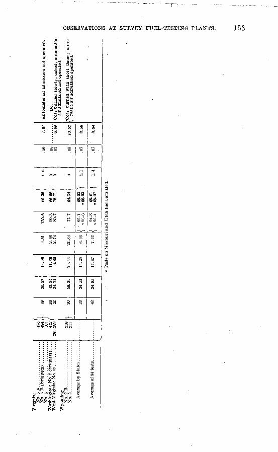
OBSERVATIONS AT SUKVEY FUEL-TESTING PLANTS. 153
S 88 8
IN "?CN U5
ofc
ssOO5
S3
..«
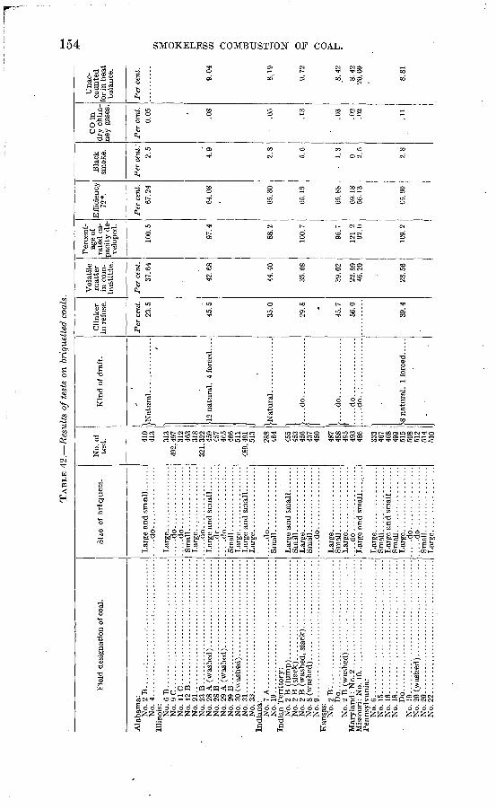
TA
BL
E 4
2.
Res
ult
s of
test
s on
bri
quet
ted
coal
s.O
l
Fie
ld d
esig
nati
on o
f co
al.
Ala
bam
a:
No.
2 B
....
.. I.........*
...................
No.
4. .
....
....
...........:
...............
Illi
nois
: N
o. 6
B ...................................
No.
9C
..........
....
....
....
....
....
....
.N
o. 1
1C
....
....
....
....
....
....
....
....
..N
o. 1
2 B
...
....
....
....
....
....
....
....
...
No.
21 ..
....
....
....
....
....
....
....
....
..N
o. 2
3 B
...
....
....
....
....
....
....
....
...
No.
28
B ...
....
...........................
No.
29
A (
was
hed)
. ..
....
....
....
....
....
.N
o. 2
9 B
...
....
...........................
No.
30
(was
hed)
...
....
....
....
....
....
...
No.
31 ....................................
No.
33............
....
....
....
....
....
....
Ind
ian
a:
No.
7 A
.........
..........................
No.
19..........
....
....
....
....
....
....
..In
dia
n T
erri
tory
: N
o. 2
B (
lum
p) ...........................
No.
2 B
(sla
ck).
..........................
No.
9.....................................
Kan
sas:
N
o. 2
B ...................................
Do....................................
No.
2 B
(w
ashe
d) ...
....
....
....
....
....
..M
aryla
nd :
No.
2 ..............................
Pen
nsy
lvan
ia:
No.
6.....................................
No.
15
....
....
....
....
....
....
....
....
....
No.
16............
....
....
....
....
....
....
No.
18............
....
....
....
....
....
....
Do....................................
No.
19............
....
....
....
....
....
....
No.
20
(was
hed)
...
....
....
....
....
....
...
No.
20
....
....
....
....
....
....
....
....
....
No.
22
....
....
....
....
....
....
....
....
....
Siz
e of
bri
quet
s.
Lar
ge a
nd
sm
all.
......
.....d
o................
.....d
o............:.
..
.....d
o................
Sm
all
.................
Sm
all
........
....
....
......d
o................
....
do
...
....
....
....
..
.....d
o................
Lar
ge. ................
No.
of
test
. 410
^llo
313
492,
497 312
463
318
321,
322
. 45
945
746
546
651
148
9, 4
91 288
464
456
40
7
450
407
488
495
493
333
467
468
4QQ
515
508
512
514
510
Kin
d of
dra
ft.
j-N
atur
al ...............
1 I. ...do.. ..............
1.... d
o.. ..............
....
.do
. ...............
....
.do..
:...
....
....
..
Cli
nker
in
ref
use.
Per
cen
t. 23
.5
45.5
oo. u
29.8
45.7
56.0
39 4
Vol
atil
e m
atte
r in
com
b
ust
ible
.
Per
cen
t. 37
.64
42.6
8
35.6
8
29.0
2
22 9
946
.20
Per
cent
ag
e of
ra
ted
ca
pa
city
de
ve
lope
d.
100.
5
97.4
oo.
L
100.
7
96.7
121
292
.0
109.
2
Eff
icie
ncy
72*.
Per
cen
t. 67
.24
64.0
8' 65
.19
65.8
8
69.1
856
.13
Bla
ck
smok
e.
Per
cen
t.'
2.5 .
4.9 . o 5.6
1.
3
0 2.5
2.8
CO
in
dry
chim
ne
y ga
ses.
Per
cen
t. 0.
05 .08
.05
.13
.03
.02
.02
.11
l
Una
c
coun
ted
for
in h
eat
bala
nce.
Per
cen
t.
9.04 . la
9.72
S. 4
2
8.42
20.0
9
8.81
tri
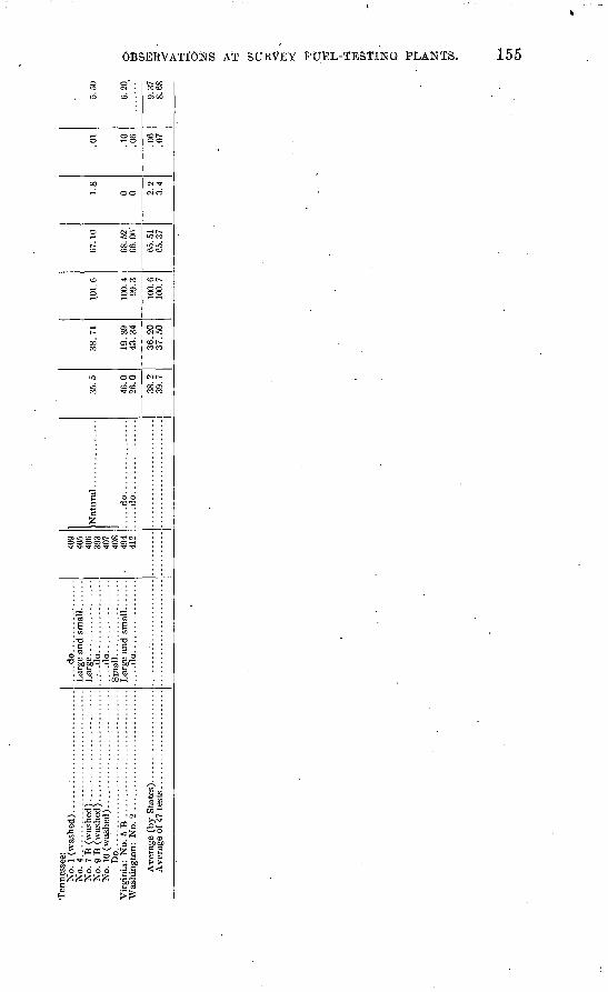
Ten
ness
ee:
No.
4..
....
....
....
....
....
....
....
....
...
No.
7B
(w
ash
ed
)...
....
....
....
....
....
..N
o. 9
B (
was
hed)
.........................
No.
10
(was
hed)
..........................
Do.
...
....
....
....
....
....
....
....
....
.....d
o................
Lar
ge. .
........
....
...
.....d
o................
Sm
all
.................
409
405
406
393
407
408
494
412
....
.do
....
....
....
....
....
.do
....
....
....
....
46.0
26
.0
38.2
39.7
19.3
94
3.3
4
36
.20
37
.50
101.
6
100.
4
100.
610
0.7
68. 5
2-
65.3
7
1 fi
0 0 2.2
3.4
.01
.10
.06
.06
.07
6.20
9.37
8.68
o
w Ui
(-3.
i (.
O Cn
156 SMOKELESS COMBUSTION OF COAL.
Table 42 is a compilation of results from all tests made on briquets at the St. Louis fuel-testing plant. The briquets all had a pitch binder and gave off little or no smoke, showing that the tile-roofed furnace used is satisfactory for burning such briquets. The vola tile matter in the combustible varied from 23 to 46 per cent and averaged about 38 per cent. The smokeless combustion of coals so high in volatile shows that briquetting has an appreciable effect on burning, especially in the furnaces of steam boilers at the rates of combustion common in stationary practice. The average per centage of the rated capacity developed on these tests was 100.6.
Table 43 is compiled from results of tests made on raw coals and the same coals washed. All the coals were washed at the fuel-testing plant, and the reductions or additions in moisture, ash, and sulphur are of interest. Most of the washed coal either burned freely (was non- coking) or seemed to burn more rapidly than the raw coal. In fact, the average percentage of rated capacity developed was considera bly greater with the washed than with the unwashed coal. This result does not indicate that the combustion chamber was more effective in one case than in the other, for .the table shows that the washed coals burned with lower efficiency and made more smoke. .
The average results show that the washed coals developed 96.6 per cent of the rated capacity, with an efficiency of 64.82 per cent, and the unwashed coals 89.9 per cent of the rated capacity, with an efficiency of 66.95 per cent. This difference in efficiency in favor of raw coal is more consistent and greater with the poorer coals than with the best.
The table emphasizes the difficulty of burning wet coal in any but a properly designed furnace. However, with a good furnace wash ing should be of advantage, as the washed coal burns more rapidly than the unwashed..
Table 44 is compiled from the results of tests made on the same coals raw and briquetted, natural draft being used in every test but one. It shows that the briquets usually burned with 1 to 3 per cent greater efficiency, developed higher capacity, and were consumed much more completely than the raw coal. Briquetting thus offers to hand-fired plants a means of developing high capacity. The plant can be run practically without smoke and obtain good efficiency by the use of briquets.
Table 45 is a comparison of results of tests made on the same coals burned with natural and with forced draft. Whenever forced draft was used the attempt was made to attain high capacity. Usually this was accomplished at the expense of efficiency. In the tests with forced draft the average percentage of black smoke was about double that, in those with natural draft. The combustion space not being
OBSERVATIONS AT SURVEY FUEL-TESTING PLANTS. 157
designed for high rates of combustion, an average variation in capac ity of 92.6 to 108.4 caused an average drop in efficiency from 64.31 to 60.94; This table demonstrates that forced draft supplied through the average grate and fuel bed will neither intimately mix the air and gases nor allow coal to be burned at high and low rates of combustion with equal efficiency.
Table 46 is a comparison of results of tests of the same coals burned on flat and on rocking grates. In all the tests but one higher effici ency (from 1 to 5 per cent, with an average of 2) was obtained with the rocking grate. The average difference in proportion of rated capacity developed was about 2 per cent and was in favor of the flat grate. However, as the rocking grate had an area of 36.4 square feet and the flat grate of 4.0.55 square feet, it is evident that the rate of combustion per square foot of grate area was at least equal on the rocking grate to that on the flat grate, or perhaps slightly greater, butas the total weight of coal burned on the flat grates was greater it involved an increased tax on the efficiency of the combustion space. The average figures for over-all efficiency of the plant show that more coal was lost in the ash pit with the rocking grate than with the flat grate, but this loss did not counterbalance the efficiency, which still shows a gain of a little more than 1.50 per cent in favor of the rocking grate.
The ash in the dry coal varied from 5.39 to 23.16 per cent and the sulphur from 0.58 to 4.78 per cent. In the sole test in which the rocking grate failed to show better results the dry coal contained about 4.50 per cent of sulphur. With both flat and rocking grates the sulphur caused trouble. The clinker fused to the grate bars so that the rocking grate as constructed was practically inoperative and was actually used as a flat grate. However, as more difficulty was ex perienced in getting the clinker off the rocking grate, the time of cleaning and inefficient operation was longer with that grate and the tests showed less efficiency, but as most plants would not have a rock ing grate to burn coal so high in sulphur, this point is unimportant. In practice about 2 per cent of sulphur is ass.umed to be the maximum content desirable for a coal to be burned on rocking grates, but this limit may be exceeded if experience shows that the sulphur is in organic form or that the sulphur and ash combined have no ill effects. The high sulphur and ash in the Wyoming coal did not cause trouble; in fact, the test was exceptional, for the coal did not clinker at all.
The black smoke was about 5 per cent less in the rocking-grate tests than in those with the flat grate. While this reduction is small the gain in efficiency with the rocking grate shows the advantage of hav ing some means of keeping the fire clean. Such a grate would be of value in hand-fired plants for decreasing smoke and increasing the efficiency of operation.
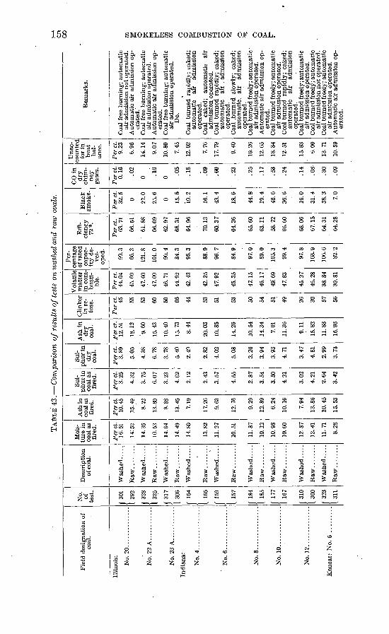
TA
BL
E 4
3.
Com
pari
son
of
resu
lts
of t
ests
on
was
hed
and
raw
coa
ls.
en
Fie
ld d
esig
nati
on o
f co
al.
Illi
nois
:
No.
20
....
....
....
..
No.
22 A
..........
..
No.
23 A
............
Ind
ian
a:
No.
4..
....
....
....
.
No.
6..
....
....
....
.
No.8
.... ...........
No.
10..............
No.
12.
.............
Kan
sas:
No.
6 .
........
No.
of
te
st.
f 30
1
1 29
2
f 32
8
1 32
5
f 31
7
I 30
6
f 15
4
1 16
5
r 159
1 15
7
J 18
4
1 18
5
I'"
I 16
7
f 31
0
(300
J 32
3
1 31
1
Des
crip
tion
of
coa
l.
Was
hed
.....
Was
hed
.....
Raw
........
Was
hed
....
.
Was
hed
.....
Raw
....
....
Was
hed
.....
Raw
....
....
Was
hed
....
.
Was
hed
.....
Raw
....
....
Was
hed
.....
Was
hed
....
.
Raw
....
....
Moi
s
ture
in
coal
as
fire
d.
Per
ct.
16.5
1
14! 5
2
14.3
5
10.5
3
14.6
4
14.4
9
14.8
0
13.8
2
11.2
7
10.5
1
11.8
7
10.1
2
10.9
8
10.6
0
12.8
7
12.4
1
11.7
1
8.28
Ash
in
coal
as
fire
d.
Per
ct.
10.4
5
15.4
9
8.22
13.8
0
8.88
13.4
5
7.19
17.2
6
9.63
12.7
6
9.29
12.8
9
6.24
10.1
6
7.94
13.8
6
10.4
5
15.5
3
Sul
phur
in
coal
as
fire
d.
Per
ct.
3.25
4.32
3.7
5.
6.07
3.23
4.62
2.12
2.43
3.57
4.55
2.87
3.54
3.50
4.21
3.02
4.21
2.64
3.42
Sul
p
hu
r in
d
ry
coal
.
Per
ct.
3.89
5.05
4.38
6.78
3.78
5.40
2.49
2.82
4.02
5.08
3.26
3.94
3.93
4.71
3.47
4.81
2.99
3.73
A s
hin
d
ry
coal
.
Per
ct.
12.5
1
18.1
2
'9.6
0
15.4
3
10.4
0
15.7
3
8.44
20.0
3
10.8
5
14.2
6
10.5
4
14.3
4
7.01
11.3
6
9.11
15.8
2
11.8
3
16.9
3
Cli
nker
in
re
fu
se.
Per
ct. 45 55
53
60
50
66
44 53
51 53 50
54
51
49 26
30
57
56
Vol
atil
e m
atte
r in
com
bu
sti
bl
e.
Per
ct.
44.0
4
45.6
9
47.6
0
47.0
9
46.7
1
44.9
2
42.4
3
42.2
5
47.9
2
45.3
5
47.1
5
46.1
7
49! 6
9
47.8
3
45.2
7
46.2
8
38.8
4
39.8
1
Per
ce
ntag
e of
rat
ed
capa
c
ity d
e
vel
op
ed.
99.3
66.3
121.
8
101.
0
90.4
84.3
95.3
88.9
96.7
84.9
97.0
89.0
105.
3
99.4
97.8
103.
9
106.
6
82.2
Eff
i
cien
cy
72*.
Per
ct.
63.7
1
66.5
1
61.8
8
66.0
9
62.9
7
68.3
1
64.9
6
70.1
3
60.3
7
64.3
6
65.6
0
63.1
1
58.7
2
66.6
0
68.0
6
67.1
5
64.3
1
64.2
8
Bla
ck
smok
e.
Per
ct.
32.5
0 27.0
25.6
0 15.5
19.2
16.1
43.4
18.6
44.8
19.4
46.6
36.6
16.0
3i.
4
38.3
7.0
CO
in
dry
ch
im
ney
gase
s.
Per
ct.
0.16 .02
0 .16
0 .05
.18
.09
.60
.23
.25
.17
.53
.24
.14
.08
.30
.09
Una
c
coun
ted
for
in
hea
t ba
l
ance
.
Per
ct.
9.23
6.96
14.1
4
9.07
10.8
0
7.45
12.0
2
7.76
17.
79
9.40
10.2
6
12.6
5
18.3
4
12.5
1
15.8
3
6.00
13.7
1
10.5
9
Rem
arks
.
Coa
l fr
ee b
urni
ng;
auto
mat
ic
air
adm
issi
on n
ot
oper
ated
. TJ
I A
utom
atic
air
adm
issi
on o
p-
g
erat
ed.'
Q
Coa
l fr
ee b
urni
ng;
auto
mat
ic
M
air
adm
issi
on o
pera
ted.
£
Aut
omat
ic a
ir a
dmis
sion
op-
S
er
ated
. y
Coa
l fr
ee b
urn
ing;
auto
mat
ic
cfi
air
adm
issi
on o
pera
ted.
CQ
Do-
. o
Coa
l burn
ed r
apid
ly;
cake
d;
2
auto
mat
ic
air
adm
issi
on
ft
oper
ated
. W
C
oal
cake
d;
auto
mat
ic
air
<3
adm
issi
on o
pera
ted.
'C
g C
oal
burn
ed r
apid
ly;
cake
d;
£j
auto
mat
ic
air
. adm
issi
on
Q
oper
ated
. ^
Coa
l .b
urne
d sl
owly
; ca
ked;
au
tom
atic
, ai
r ad
mis
sion
Q
op
erat
ed.
hcj
Coa
l burn
ed f
reel
y; a
uto
mat
ic
air
adm
issi
on o
pera
ted.
^
Aut
omat
ic a
ir a
dmis
sion
op-
P
er
ated
. r^
C
oal b
urn
ed f
reel
y; a
uto
mat
ic
F
air
adm
issi
on o
pera
ted.
C
oal
burn
ed r
apid
ly;
cake
d;
auto
mat
ic
air
adm
issi
on
oper
ated
. C
oal b
urn
ed f
reel
y; a
uto
mat
ic
air
adm
issi
on o
pera
ted.
C
oal b
urn
ed f
reel
y; a
uto
mat
ic
air
adm
issi
on n
ot
oper
ated
. C
oal b
urn
ed f
reel
y; a
uto
mat
ic
air
adm
issi
on o
pera
ted.
A
utom
atic
air
adm
issi
on o
p
erat
ed.
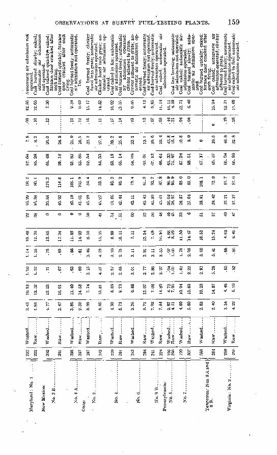
New
Mex
ico:
No
.3B
....
.........
No.
4 A
..........
...
Ohi
o: No.
2............
...
No.
4..
....
....
....
.
No.
6............
...
No.9
B..
...
....
....
Pen
nsyl
vani
a:
No
.5..
....
....
....
.
No.
7..
...
...
Ten
ness
ee:
Nos
. 8 A
and
8
B.
Vir
gini
a:
No.
2......
...
1 23
2
1 22
2
f 39
2
[ 39
1
J 39
8
1 39
7
f 19
7
[ 19
3
f 22
0
1 20
1
f 25
3
1 28
4
| 24
1
f 19
5
( l9
?
1 30
7
f 38
8
1 38
4
J 20
0
1 25
6
Was
hed
.....
Was
hed
.....
Raw
........
Was
hed
.. ...
Raw
........
Was
hed
.....
Raw
........
Was
hed
.....
Raw
....
....
Was
hed
.....
Was
hed
.....
Was
hed
.....
Was
hed
.....
Was
hed
.....
Was
hed
.....
Raw
........
3.43
1.84
4.77
2.47
3.86
2.30
8.99
8.86
4.30
3.73
3.26
3.71
7.92
7.84
2.97
4.11
4.80
5.80
2.83
2.40
3.34
4.22
10.1
3
12.5
2
12.2
3
16.9
1
11.4
0
14.5
8
7.74
13.8
1
6.69
9.73
6.88
12.0
7
7.08
14.8
9
4.73
10.9
4
13.6
3
10.2
3
14.8
7
4.48
6.19
I.'IO
1.52 .71
.67
.63
.60
3.15
4.37
2.97
2.65
3.01
3.77
2.86 .'9
4
1.01
1.62
2.92
5.28 .8
5
.82
1.14
1.55 .75
.69
.66
.61
3.46
4.79
3.10
2.75
3.11
3.91
3.11 .9
71.
05
1.70
2.36
3.00
5.41 .8
8
.86
10.4
8
12.7
6
12.8
5
17.3
4
11.8
6
14.9
2
8.50
15.1
5
6.99
10.1
1
7.11
12.5
4
7.69
16.1
6
4.88
o. /
y
11.5
0
14.4
7
10.5
3
15.2
4
4.63
6.46
22 38 0 0 0 0 50 42 34
, 51 60 52 56 48 40 *J 33 0 51
57 40
47
16.2
9
16.3
8
39.8
8
40.9
2
40.1
9
41.6
1
45.2
9
45. 2
7
43.6
0
42.4
4
43.1
1
43.4
3
45.3
9
45.6
1
38.0
4
26.8
7
27.0
4
39.9
1
39.4
2
39.2
1
37.3
7
93.2
80.1
119.
2
114.
8
108.
1
103.
9
84.4
80.3
93.2
93.2
79.4
81.3
92.7
87.8
96.9
88.6
85.0
106.
1
72.8
87.7
87.6
67
.64
65.
28
65.
48
69
.18
65
.83
63
.86
62
.54
64
.33
63.
19
66
.14
64
.08
69
.01
67.
13
66
.61
65
.33
7
1.9
7
67
.24
68
.51
67.
17
65
.37
65.9
4
65
.93
7.5
. 8.2
26.0
24.5
. 21
.0
16.5
32.2
27.6
J39.
2
.25.
8
23.2
13.1
39.6
22.4
43.8
15
.1
10.8
8.0
o 10
.5
40.8
32.8
.08
.10
.12
.12
.12
.15
.11
.17
.14
.23
.13
.07
.05
.44
.21
.04
.04
0 .19
.26
12.8
6
12.6
3
7.30
9.34
9.69
15.1
7
14.8
2
16.0
2
13.3
5
9.85
4.12
9..S
5
11.1
4
15.1
1 4.
59
12.7
1
6.40
15.2
4
13.7
1
11.6
9
Aut
omat
ic a
ir a
dmis
sion
no
top
erat
ed.
Coa
l burn
ed
slow
ly;
cake
d;au
tom
atic
ai
r ad
mis
sion
no
t op
erat
ed.
Coa
l bu
rned
qu
ick
ly!
cake
d;fu
rnac
e do
or c
rack
ed a
fter
each
fir
ing.
C
oal
burn
ed q
uic
kly
; fu
rnac
edo
or
crac
ked
afte
r ea
chfi
ring
. C
oal
burn
ed f
reel
y; a
uto
mat
icai
r ad
mis
sion
not
oper
ated
. D
o.
Coa
l b
urn
ed
free
ly;
clin
ker
fuse
d in
to g
rate
; au
tom
atic
ai
r ad
mis
sion
ope
rate
d.C
link
er f
used
int
o gr
ate;
au
to
mat
ic a
ir
adm
issi
on
op
erat
ed.
Coa
l ca
ked
in f
ire;
auto
mat
ic
air
adm
issi
on o
pera
ted.
Coa
l bur
ned
free
ly;
auto
mat
ic
air
adm
issi
on
oper
ated
; cl
inke
r ad
here
d to
gra
te.
Cli
nker
adh
ered
to
grat
e; a
u
tom
atic
ai
r ad
mis
sion
op
er
ated
.C
oal
burn
ed f
reel
y; a
uto
mat
ic
air
adm
issi
on n
ot
oper
ated
.C
oal b
urne
d fr
eely
; au
tom
atic
ai
r ad
mis
sion
ope
rate
d.C
oal
cake
d;
auto
mat
ic
air
adm
issi
on o
pera
ted.
Coa
l fr
ee b
urni
ng;
auto
mat
ic
air
adm
issi
on n
ot
oper
ated
.C
oal
cake
d;
auto
mat
ic
air-
ad
mis
sion
ope
rate
d.C
oal
burn
ed
slow
ly;
auto
m
atic
ai
r ad
mis
sion
op
er
ated
.C
oal
burn
ed q
uick
ly;
cake
d;
furn
ace
door
cra
cked
aft
er
each
fir
ing.
Coa
l ca
ked;
au
tom
atic
ai
r ad
mis
sion
ope
rate
d; c
link
er
adhe
red
to g
rate
.C
oal b
urne
d fr
eely
; au
tom
atic
ai
r ad
mis
sion
ope
rate
d.C
oal
cake
d in
fir
e; a
uto
mat
ic
air
adm
issi
on o
pera
ted.
CD
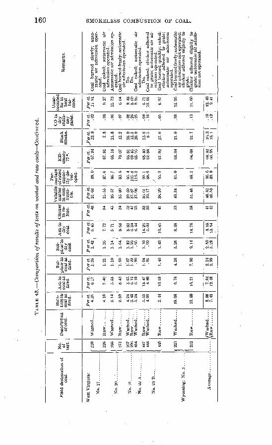
TAB
LE 4
3.
Com
pari
son
of r
esul
ts o
f tes
ts o
n w
ashe
d an
d ra
w c
oals
Con
tinu
ed.
Fie
ld d
esig
nati
on o
f co
al.
Wes
t V
irgi
nia:
No.
17..............
No.
20
....
....
....
..
No.
21..............
No.
22
A............
No.
23
B. .
...........
Ave
rage
...
....
...
No.
of test
.
( 23
0
[ 22
6
J 26
6
1 27
3
267
296
454
447
f 44
4
1 44
5
223
212
Des
crip
tion
of
coa
l.
Was
hed
.....
Was
hed
.....
Raw
........
Was
hed
.....
Was
hed
.....
Was
hed
.....
Was
hed
....
.
Raw
....
....
/Wash
ed
.....
Moi
s
ture
in-
coal
as
fire
d.
Per
ct.
4.35
4.10
3.14
2.89
4.24
3.
42
5.24
5.55
4.
06
2.44
19.0
8
13.6
0
8.06
7.
48
Ash
in
coal
as
fire
d.
Per
ct.
6.17
7.40
5.53
8.43
3.67
. 6.
12
6.10
13.4
7 4.
80
10.5
9
6.78
16.2
1
7.84
12
.48
Sul
phur
in
coal
as
fire
d.
Per
ct.
1.36
1.21
1.10
'1.5
0
1.'0
7 1.
22
.90
1.04
.9
5
1.40
4.26
7.90
2.24
2.
99
Sul
phur
in
dry
co
al.
Per
ct.
1.42
1.26
1.14
1.54
1.12
1.26
.9
5
1.10
.9
9
1.43
5.26
9.14
2.50
3.
29
Ash
in
dry
co
al.
Per
ct.
6.45
7.72
5.71
8.68
3.83
6.
34
6.44
14.2
6 5.
00
10.8
5
8.38
18.7
6
8.58
13
.54
Cli
nker
in
re-
fu
se.
Per
ct.
48 34
45
34 52
47
25 33
30 41
53 58 41
42
Vol
atil
e m
atte
r in
com
bu
sti
bl
e.
Per
ct.
31.6
8
31.5
5
36.5
7
35.8
0
39.5
9 37
.87
37.9
8
36.6
1 39
.17
38.2
9
49.3
4
51.4
6
40.8
2 40
.50
Per
ce
ntag
e of
rate
d
capa
c
ity d
e
vel
op
ed.
89.0
87.6
86.7
83.6
95.4
10
1.8
110.
3
99.1
88
.0
95.9
81.0
88.2
96.6
89
.9
Eff
i
cien
cy
72*.
Per
ct.
67.9
4
67.8
1
66.1
8
70.0
7
66.8
1 69
.45
65.9
5
68.4
0 62
.84
67.9
3
63.3
4
64.0
8
64.8
2 66
.95
Bla
ck
smok
e.
Per
ct.
23.8
7.8
21.8
12.2
36.0
13
.5
20.0
13.0
8.
5
27.0
21.0
22.7
26.3
18
.1
CO
in
dry
ch
im
ney
ga
ses.
Per
ct.
.02
.06
.06
.07
.08
.26
.25
.04
.16
.05
.30
.13
.19
.12
Una
c
coun
ted
for
in
heat
ba
l
ance
.
Per
ct.
11.9
1
9.37
11.7
3
6.04
9.48
8.
60
9.96
6.71
10
.66
6.97
12.2
6
11.6
0
12.4
0 9.
41
Rem
arks
.
Coa
l bu
rned
sl
owly
; au
to
mat
ic a
ir
adm
issi
on
oper
at
ed.
Coa
l ca
ked;
au
tom
atic
ai
r ad
mis
sion
ope
rate
d.
Aut
omat
ic a
ir a
dmis
sion
op
er
ated
. C
oal b
urne
d fr
eely
; au
tom
atic
ai
r ad
mis
sion
ope
rate
d.
Do.
D
o.
Coa
l ca
ked;
au
tom
atic
ai
r ad
mis
sion
ope
rate
d.
Do.
C
oal
cake
d;
clin
ker
adhe
red
to g
rate
; au
tom
atic
air
ad
m
issi
on o
pera
ted.
C
oal
burn
ed q
uick
ly;
cake
d;
clin
ker
adhe
red
to
grat
e;
auto
mat
ic
air
adm
issi
on
oper
ated
. C
oal b
urne
d fr
eely
; aut
omat
ic
air
adm
issi
on n
ot o
pera
ted;
cl
inke
r ad
here
d sl
ight
ly t
o gr
ate.
C
linke
r ad
here
d sl
ight
ly
to
grat
e; a
utom
atic
air
adm
is
sion
not
ope
rate
d.
05
O
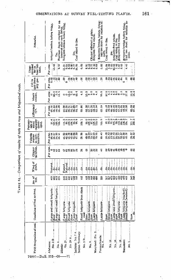
TAB
LE 4
4.
Com
pari
son
of r
esul
ts o
f te
sts
on r
aw a
nd b
riqu
ette
d co
als.
Fie
ld d
esig
nati
on o
f coa
l.
Ala
bam
a:
No.
2 B
..... ,. .....
No.
4..
....
....
....
.Il
lino
is:
No.
21..............
No
.29
B.. .........
Ind
ian
a: N
o. 7
A ...
....
India
n T
erri
tory
:
No.2
B...... .....
..
No.
9..
....
....
....
.
Mar
ylan
d :
No.
2. .
....
.
Pen
nsyl
vani
a:
No.
15
....
....
....
..
No.
16..
....
....
....
No
19
T n
ness
ee-
No.
1. .
............
.
Con
diti
on o
f fu
el a
s fi
red.
/Lar
ge a
nd s
mal
l bri
quet
s. .
/Lar
ge a
nd s
mal
l bri
quet
s..
/Lar
ge b
riquet
s ............
/Sm
all
bri
quet
s ..
....
....
..
(Lar
ge b
riquet
s. ...........
(Sm
all
bri
quet
s fr
om s
lack
/Sm
all
bri
quet
s ............
\Raw
. ..
....
....
....
....
...
/Lar
ge
bri
quet
s. ..........
Lar
ge b
riquet
s ..
....
....
..
Sm
all
bri
quet
s ............
Lar
ge b
riquet
s ..
....
....
..
....
do..
....
....
....
....
..
No.
of
test
.
410
OO
^
413
G/O
318
O1U
466
288
453
418
450
449
493
333
217
467
468
471
508
498
409
345
346
Kin
d o
f d
raft
.
Nat
ura
l . .
....d
o......
...d
o.......
...d
o......
Fo
rced
....
...d
o......
...d
o......
...d
o..
....
....d
o......
...d
o..
....
.
...d
o......
...d
o......
...d
o......
...d
o......
...d
o......
...d
o......
...d
o......
...d
o.......
...d
o......
...d
o......
...d
o.......
...d
o......
...d
o.......
...d
o......
...d
o......
...d
o......
...d
o..
....
Cli
nker
in
ref
use.
Per
cen
t. 0 oo 47 \r± 47 38 37 34 48 26
56 O
A 43 54 39 41 40 34 46
26 0 44 53
Vol
atil
e m
atte
r in
com
b
ust
ible
.
Per
cen
t. 38
.94
OO
. O
l
36.3
3
41.8
342
.35
45.7
9
42.8
4
39.8
8
40.8
119
.23
22.9
9
39.4
5
38.5
926
.53
27.4
324
24
37.7
7
40.5
640
.31
39.8
738
.83
Per
cent
ag
e of
ra
ted
ca
paci
ty
deve
l
oped
.
91.4
108.
6 10
9.5
1U
U.
o
115.
3O
y.
O
109.
2
84! 5
105.
1
95.0
102.
2
121.
2
105.
9
97.1
99.0
105.
798
911
3.7
106.
8 11
0.3
134.
7
111.
710
9.5
Eff
icie
ncy
72*.
Per
cen
t. 69
.52
64.9
5
64.0
0
66.9
1o*
±. o/
66
.08
69.6
6
68.3
807
.77
65.2
0 69
.18
65.6
4
66.3
970
.08
68.2
2fi
Q
OQ
67.2
365
.84
68.0
670
.26
66.0
967
.90
Bla
ck
smo
ke.
Per
cen
t. 0 30
.0
5.0
11.5
0 0 13.0 7.0
0 4.5
15.5
0 3.0
0 15.5
37.8 5.5
4.0
Q
1-1
0 4.5
0 17.0
14.0
16.5
CO
in
dry
chi
m
ney
gas
.
Per
cen
t. 0.
02 . 10
.07
.05
.02
0 .04
.07
.06
.09
.05
.17
.02
.10
.20
.30
.03
.04
.02
.02
.04
0 .10
.09
.05
Una
c
coun
ted
for
in
hea
t ba
l
ance
.
Per
cen
t.
. yi
11.0
1
s!o3
. ou
6.77
6.02
8.91
8.53
8.77
8.
42
5.83
11.0
47.
89
10.0
57.
487.
078.
65
4 AC
Rem
arks
.
Bri
quet
bro
ken
befo
re f
irin
g.
Do.
inte
rval
aft
er e
ach
firi
ng.
Bri
quet
s br
oken
bef
ore
firi
ng.
Do.
Cli
nker
adh
ered
to
gra
te.
Bri
quet
s fi
red
who
le.
f B
riquet
s br
oken
bef
ore
firi
ng;
i te
st t
oo s
hort
for
rel
iabl
e re
-[
suit
s.
Do.
.Bri
quet
s fi
red
who
le.
w
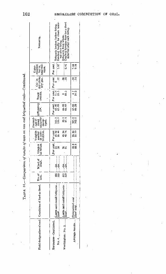
TAB
LE
44
.- C
ompa
riso
n o
f re
sult
s of
test
s on
raw
and
bri
quet
ted
co
als
Con
tinu
ed.
Fie
ld d
esig
nati
on o
f coa
l.
Ten
ness
ee C
on
tin
ued
.
No.
4..............
Was
hing
ton:
No.
2. .
...
Con
diti
on o
f fu
el a
s fi
red.
Raw
. .....................
No.
of
test
.
355
412
359
Kin
d o
f .
dra
ft.
...d
o..
....
...d
o..
....
...d
o......
...d
o..
....
Cli
nkor
in
ref
use.
Per
cen
t. 25 38 26 61 32
.848
.3
Vol
atil
e m
atte
r in
com
bust
ible
.
Per
cen
t. 39
.92
38.4
4
43.3
443
.14
36.4
435
.19
Per
cent
ag
e of
ra
ted
ca
paci
ty
deve
l
oped
.
105.
311
0.8
99.3
97.4
107.
010
2.2
Eff
icie
ncy
72*.
Per
cen
t. 69
.00
67.0
5
66.0
666
.65
67.6
666
.25
Bla
ck
smoke.
Per
cen
t. 11
.023
.5
0 33.5
- 4.
716
.2
CO
in
dry
chi
m
ney
gas
.
Per
cen
t. 0 .2
7
.06
.23
.05
.14
Una
c
coun
ted
for
in
hea
t ba
l
ance
.
Per
cen
t.
7.97
6.41
7.64
9.54
Rem
arks
.
Sm
oked
bad
ly f
or s
hort
int
er
val
afte
r fi
ring
.
Cra
cked
fur
nace
doo
r fo
r a s
ho
rtin
terv
al a
fter
eac
h fi
ring
.
Oi
w
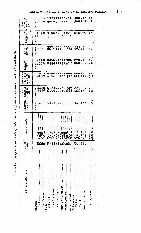
TA
BL
E 4
5
Com
pari
son
of
resu
lts
of
test
s of
the
sam
e fu
els
whe
n us
ing
natu
ral
an
d fo
rced
dra
fts.
Fie
ld d
esig
nati
on o
f fu
el.
Ark
ansa
s:
No.
7 A
...........
...............:
...................
Illi
nois
:
Wes
t V
irgi
nia
: N
o. 5
A..............................................
No.
15.
..............................................
No.
of
test
.
/ 29
4\
293
/ 30
9\
308
/ 50
550
0 49
249
7 32
232
1 /
332
1 33
0 /
506
\ 49
6 /
385
\ 38
4
I 48
2)
476
/ 21
61
215
f 21
3I
210
Kin
d o
f dr
aft.
For
ced ..
....
....
....
...
For
ced .................
For
ced .................
For
ced .................
For
ced .................
Nat
ural
................
For
ced .................
Nat
ural
................
For
ced .................
For
ced .................
Nat
ural
................
For
ced .................
Nat
ural
................
For
ced .................
Nat
ural
................
For
ced .................
Nat
ural
................
/For
ced.
.................
^N
atu
ral.
...............
Cli
nker
in
refu
se.
Per
cen
t.57 52 28 36
57 55
. 51 36
62 62
61 55
St
t51
55 57
62 51
49 0 0 48.9
Vol
atil
e m
atte
r in
co
mbu
sti
bl
e.
Per
cen
t. 19
.07
19.0
7 12
.51
45.8
710
. yj
.45
.28
rtZ
. U
D46
.61
44. 4
845
.40
32.5
4O
O-
1 O
39.8
5
14.7
5J.
f>. lo
42.9
242
.71
51.5
850
.01
35.9
Per
cen
tag
e of
rat
ed c
a
pac
ity d
e
velo
ped.
85.7
1 £»
O
106.
380
.9
131.
6
98.2
oO
. &
106.
6
129.
411
5.0
98.0
101.
0 86
. 5t Z
, o
147.
799
.7
103.
084
.4
99.9
88.3
108.
4
Eff
icie
ncy
72*.
Per
cen
t. 65
.07
oy. o
& 62
.92
60.2
0\j
£i*
OO
62.9
7
58.2
2oo
. yo
56.6
462
. 03
63.4
6
63.3
365
. 37
60.2
367
.13
60.3
062
.91
56.9
8
60.9
464
. 41
Bla
ck
smok
e.
Per
cen
t. 0 0 0 0 149
43
0 17.0
42! 5
£it
. O
9.0
7.0
28.0
20.5 1.5
546
42.0
0 21.2
12.2
CO
in d
ry
flue
gas
es.
Per
cen
t. 0.
02 .'57
lA
>
.10
.11
.06
.05
.14
.02
.17
0 . .04 .03
.05
0 .20
.45
&
\J
.53
. 06
.21
.08
Una
c
coun
ted
for
in h
eat b
al
ance
.
Per
cen
t. 9.84
11.1
3
10.5
8
8.85
7.03
17
.43
17.0
5 13
.63
8.30
14.8
0J.
O.
Z1
15.4
5
18.2
21O
. O
.L19
.03
13.3
910
.84
O 3
GO 6 CO d o OO
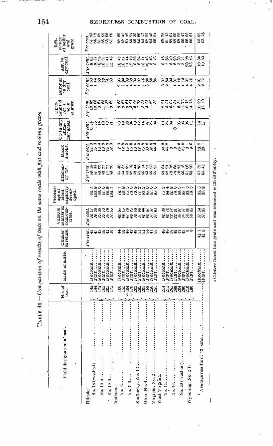
TAB
LE 4
6.
Com
pari
son
of
resu
lts
of
test
s on
the
sam
e co
als
wit
h fi
at
and
rock
ing
grat
es.
C5
Fie
ld d
esig
nati
on o
f coa
l.
Illi
nois
: N
o. 1
3 (w
ashed
). .............................
No.
19
A ...
....
....
....
....
....
....
....
....
..
Ind
ian
a:
No.
7 B
......................................
Wes
t V
irgi
nia:
N
o. 1
5 ..
....
....
.............................
No.
19 ..
....
....
.............................
No.
20
(was
hed
).. ...........................
No.
of
test
.
I 14
5\
144
1 17
1"
/ 20
5
/ 16
6\
151
/ o!6
4
/ 26
3\
265
/ 20
1\
188
/ 25
6\
251
f 21
4
/ 28
5t
289
1 26
4\
266
/ 21
0\
196
Kin
d o
f g
rate
.
Rock
ing
.......
Fla
t.:.
.......
Rock
ing
.......
Fla
t...
....
...
Rock
ing.... ...
Fla
t...
....
...
Rock
ing. .
.....
Fla
t...
....
...
Rock
ing
. .....
Fla
t..........
Rock
ing
.......
Fla
t..........
Rock
ing. .
.....
Fla
t...
....
...
Rock
ing. .
.....
Fla
t...
....
...
Rock
ing. .
.....
Fla
t...
....
...
Rock
ing
.......
Fla
t...
....
...
Rockin
g.......
Fla
t...
....
...
Roc
king
. ......
Fla
t...
....
...
/Rock
ing
. ......
\Fla
t..........
Cli
nker
in
refu
se.
Per
cen
t. 45 47
45 Oo 41 10
44 Oo 43 42
49 51
51 Oo
47 46 56 48
33 0 0
41.7
Vol
atil
e m
atte
r in
co
mbu
s
tibl
e.
Per
cen
t. 38
.17
oy. O
o 35
.38
oO.
Oo
36.7
4
42.8
544
.15
47.7
948
.25
38.6
8o
/. y
o42
.44
14
. O
t
37.3
737
.43
42.3
8
22.'
62££.
OJ.
36.0
7
50.0
1O
U.
UJ
37.5
437
. 95
Per
cen
t
age
of
rate
d
capac
ity
deve
l
oped
.
94.7
J,U
o- o
90.6
Of.
O94
.910
4.7
74.7
ou.
o75
.5/o
. o
78.9
i i.
£i
9a2
95.0
87
.6
75.2
81.8
79. 6
90
.5oO
. /
88.3
79.3
85.5
87.8
Eff
icie
n
cy 7
2*.
Per
cen
t. 69
.15
69.0
9
71.2
7
66.3
8
60.8
9O
^. l
o68
.44
65.9
5 66
.14
65.9
365
.91
68.5
4\j£
f yi
70.7
6
70.2
3
61.0
6U
O.
£t\J
67.3
2
Bla
ck
smok
e.
Per
cen
t. 28
.0
13.0
J.O
. V
28.8
2.0
\.£i
. o
15.2
16. 0
13
.6
25^8
32.8
32.8
0 0 26.0
4-L
. 0
0 18.2
ZO
. 1
CO
in d
ry
chim
ney
gas
es.
Per
cen
t. 0.
34 .14
. -L
O
,10
.28
.08
.04
.13
!l4
A
t
.26
.10
.26
.04
0 .05
!06
.11
.14
.17
Una
c
counte
d
for
in
hea
t ba
lanc
e.
Per
cen
t. 12
.52
9.81
11.6
5 7.
37
8.53
9.57
19
.61
J.O
. £t
i~6.
26 . /o
ia35
11.6
911
.80
12.2
1±
O-
OJ.
6.04
8.34 . /O
16.1
614
.75
10-9
917
.40
Sulp
hur
in d
ry
coal
.
Per
cen
t.
1.50 .58
. G
o.6
1
OO
2.96
£i. V
i
4.39
1.03
1.02
2.
75o.
oU
.8
6
oO
a 07
L.
Orz
.94
1.10
1.14
4.
374.
78
2.01 . 1
0
Ash
in
dry
coa
l.
Per
cen
t. 8.
03
10.2
810
.25
11.4
1
18.4
9
11.4
4j.j£
. i.y
6.
62
10.1
1
6.46
8.18
/. o
O6.
706.
90
' 5.
395.
71
20.9
8Z
o.
JLU
10.3
4
Eff
i
cien
cy
of b
oile
r an
d
grat
e.
Per
cen
t. 67
.93
66.1
2 67
.06
68.8
667
.50
62.6
062
.41
59.4
9
6&38
64.8
8 64
.17
64.4
8
62.7
6
69.0
4
69.2
6
v 58
.66
65.0
6
CO g
O
a C
linker
fuse
d i
nto
gra
te a
nd w
as r
emov
ed w
ith d
iffi
cult
y.
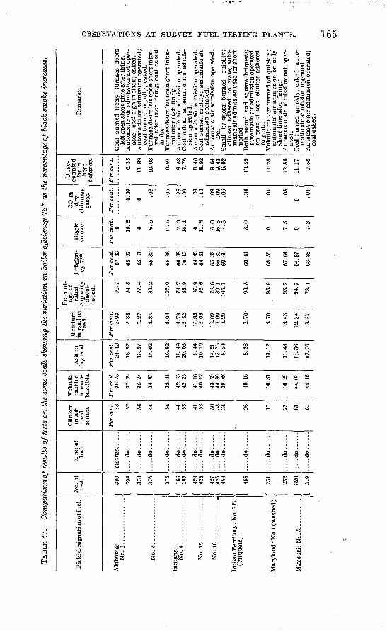
TAB
LE 4
7.
Com
pari
son
of r
esul
ts o
f te
sts
on t
he s
ame
coal
s sh
owin
g th
e va
riat
ion
in b
oile
r ef
fici
ency
72
* as
the
per
cent
age
of
blac
k sm
oke
incr
ease
s.
Fie
ld d
esig
nati
on o
f fue
l .
Ala
bam
a:N
o. 3
................
Indi
ana:
N
o. 4
....
....
....
....
No.
15.
...
....
....
...
Ind
ian
Ter
rito
ry:
No.
2 B
(b
riqu
ets)
.
Mar
ylan
d: N
o.l
(was
hed)
Mis
sour
i : N
o. 5
. ..........
No.
of
test
.
J 39
0
1 39
4 1378
376
375
f 16
6\
165
f 42
9J
49
Q
/ 42
7X
426
14
53 455
f 23
1
I 23
2
J 32
0
1 31
9
Kin
d of
dr
aft.
....
.do
....
..
.....d
o......
....
.do
....
..
.....d
o......
....
.do
....
....
...d
o..
....
....
.do
....
....
...d
o..
....
.....d
o......
....
.do
....
..
....
.do
....
..
.....d
o......
.....d
o......
.....d
o......
.....d
o......
.....d
o......
Cli
nker
in
ash
an
d re
fuse
.
Per
cen
t. 43 52 54 44 44 53
41 53 50 53
34 26 17 22 63
61
Vol
atil
e m
atte
r in
com
bu
stib
le.
Per
cen
t. 36
.75
37.5
9
35.2
4
34.8
3
35.4
1
42.8
5
41.1
640
.12
43.5
944
.89
39.8
8
40.1
6
16.3
1
16.2
9
44.0
3
44.1
6
Ash
in
dry
coa
l.
Per
cen
t. 21
.42
18.9
7
13.9
7
15.0
2
10.9
2
18.4
920
.03
9.44
14.2
113
.75
8.59
8.28
10.4
8
18.3
6
17.7
6
Moi
stur
e in
coa
l as
fi
red.
Per
cen
t. 2.
93
2.88
5.27
4.84
14.7
913
.82
12.8
313
.05
10.0
99.
09
3.29
2.70
-
3.70
3.43
12.2
4
13.3
7
Per
cent
ag
e of
ra
ted
ca
pac
ity
deve
l
oped
.
92.7
94.8
77.4
83.2
74.7
88.9
87.9
9C
C\
78.6
89.1
10
5.1
93.2
94.7
78.1
Eff
icie
n
cy 7
2*.
Per
cen
t. 67
.43
65.6
2
65.6
1
65.8
2
66.3
8
66.3
8
64 4
3
65.3
266
.30
69.6
6
60.4
1
68.5
6
67.6
4
64.8
7
63.2
8
Bla
ck
smok
e.
Per
cen
t.
0 16.5
0 6.5
11.5
2.0
0 6.0
16.5
A
K
8.0
0 0 7.2
CO
in
dry
ch
imne
y ga
ses.
Per
cen
t.
0.09
0 .08
.05
.28
.09 no 13 .09
.09
.06
.34 04 .08
0
Una
c
coun
ted
for
in
hea
t ba
lanc
e.
Per
cen
t.
6.35
11.8
9
10.0
8
9Q
7
8.53
9 46
8 no
9.64
'9.
43
6.02
10
C
Q
Uoo
12.8
6
11.1
7
9=
0
Rem
arks
.
ated
; co
al h
igh
in s
lack
; ca
ked.
coal
bu
rned
rap
idly
; ca
ked.
F
urn
ace
door
s le
ft o
pen
sho
rt i
nter
va
l af
ter
each
fir
ing;
coa
l ca
ked
in f
ire.
val
afte
r ea
ch f
irin
g.
Aut
omat
ic a
ir a
dmis
sion
ope
rate
d.C
oal
cake
d; a
utom
atic
ai
r ad
mis
si
on o
pera
ted.
adm
issi
on o
pera
ted.
A
utom
atic
air
adm
issi
on o
pera
ted.
Do.
clin
ker
adhe
red
to
grat
e; a
uto
m
atic
air
adm
issi
on u
sed
for s
ho
rt
peri
od.
auto
mat
ic a
ir a
dmis
sion
ope
rate
d on
par
t of
tes
t; c
link
er a
dher
ed
to g
rate
.
auto
mat
ic a
ir a
dmis
sion
on
only
sh
ort
tim
e af
ter
firi
ng. '
ated
. C
oal
burn
ed q
uick
ly;
cake
d; a
uto
m
atic
air
adm
issi
on o
pera
ted.
coal
cak
ed.
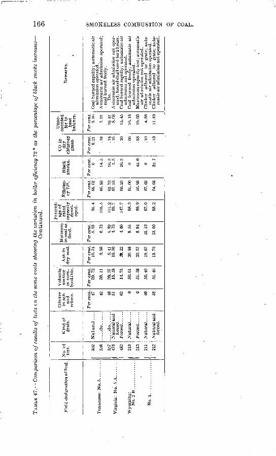
TAB
LE 4
7.
Com
pari
son
of r
esul
ts o
f te
sts
en t
he s
ame
coal
s sh
owin
g th
e va
riat
ion
in b
oile
r ef
ficie
ncy
72*
as
the
perc
enta
ge o
f bl
ack
smok
e in
crea
ses-
C
on
tin
ued
.O
S
C5
Fie
ld d
esig
nati
on o
f fue
l.
Ten
ness
ee:
No.
5. .
.......
Vir
gini
a: N
o. 5
A.....
"Wyo
min
g:
No
.2B
. .............
1
No.
3.-
....
..'...
..
No.
of
test
.
352
357
476
1 48
2
f 21
0
1 21
3
j 21
1
1 21
2
Kin
d o
f dra
ft.
Nat
ura
l ....
.....d
o......
.....d
o......
Nat
ura
l an
d
Nat
ura
l .....
Nat
ura
l an
d fo
rced
.
Cli
nker
in
ash
. an
d
refu
se.
Per
cen
t.
47 49 46 51 62 0 0 60 58
Vola
tile
' m
atte
r in
com
bust
ible
.
Per
cen
t.
39.7
2
39 1
1
39.3
715
.18
14.7
5
50.0
1
51.5
8
50.4
0
51.4
6
Ash
in
dry
coa
l.
Per
cen
t. 10
.34
9 98
9.4
119.5
0
16.2
2
20.9
8
23.5
7
19.6
7
18.7
6
Moi
stur
e in
coa
l as
fire
d.
Per
cen
t. 5.
59
5.8
24.7
3
4.6
0
9.5
5
8.9
4
15.1
2
13.6
0
Per
cen
t
age
of
rate
d
capac
ity
deve
l
oped
.
95.4
115.
5
111.
299
.7
147.
7
88.3
99.9
'
67.0
88.2
Eff
icie
n
cy 7
2*.
Per
cen
t. 65
.62
67.1
3
61.0
6
56
.98
64.0
8
Bla
ck
smok
e.
Per
cen
t. 0 14
.5 1.5
0 0 22.7
CO
in
dry
ch
imn
ey
gase
s.
Per
cen
t. 0.
21 is .16
9ft
.06 VI
.10
.13
Un
ac
coun
ted
for
in
hea
t ba
lanc
e.
Per
cen
t. 9.
86
7 91
10.3
18
.68
1 ^
4^
16.1
6
19.0
3
4.8
8
11.
CO
Rem
ark
s.
Coa
l burn
ed r
apid
ly;
auto
mat
ic a
ir
adm
issi
on o
pera
ted.
coal
burn
ed f
reel
y.
Do.
Auto
mat
ic a
ir a
dmis
sion
no
t op
er-
adm
issi
on n
ot
oper
ated
. C
oal
burn
ed
free
ly;
auto
mat
ic a
ir
air
adm
issi
on n
ot
oper
ated
.
Cli
nker
ad
here
d to
gr
ate;
aut
o
mat
ic a
ir a
dmis
sion
not
oper
ated
.
METHODS OF SUPPLYING AIK FOE COMBUSTION. 167
Table 47, compiled from the results of tests made on the same coals, shows the variation in boiler efficiency as the smoke increases. The tests of each coal compared were made with the same boiler and same grate. All the tests but two were made with natural draft; but inasmuch as the use of forced draft only increased the rate of com bustion, as was shown by Table 45, the tests are comparable both as to efficiency and smoke.
In general the results show that as the percentage of rated capacity developed increased the percentage of black smoke increased and the efficiency decreased. . This proves that the combustion space was not efficient over a wide range of working conditions, but there was a limit for rate of combustion for each kind of coal, above which effi cient operation was impossible. The table also demonstrates that with hand-fired furnaces the combustion space to be most efficient must have some means of mixing the air and gases. The results with Maryland and Indian Territory coals show that the most smoke was made on the tests showing low capacity. Methods of operation may account for this efficiency variation, as with the Maryland coal the automatic air admission was used on the high-capacity test and not on the low. The discordant results in the tests of Indiana coals are probably due to the variation in air admission. The beneficial effect of the automatic air admission in reducing the smoke and increasing efficiency is noticeable in several tests.
The three tests on Alabama coal were run at about equal efficiency over a wide range of capacity, but as-the methods of operating were dissimilar -these apparent discrepancies could easily result.
High smoke values gave high unaccounted for values in the heat balance. "Usually the percentage of CO in the'flue gas was much greater when the smoke was high, showing a cause for the decreasing efficiency and increasing visible evidence of loss noted with high rates of combustion.
COMPARISON OF METHODS OF SUPPLYING AIR FORCOMBUSTION.
METHODS COMPARED.
As supplementing the data already presented to show the results obtained in tests at the fuel-testing plants, a number of tables have been compiled to show the relative value of different methods of supplying air for combustion. The following methods are compared: (1) Air supplied continuously by means of openings in grates; (2) air taken continuously through the grates and an extra amount supplied automatically at times of greatest distillation of volatile matter; (3) air taken continuously through the grates and more supplied at times of firing by cracking the furnace doors. All full-length St. Louis tests (except the briquet tests) and the hand-fired Norfolk tests have been used in this compilation.
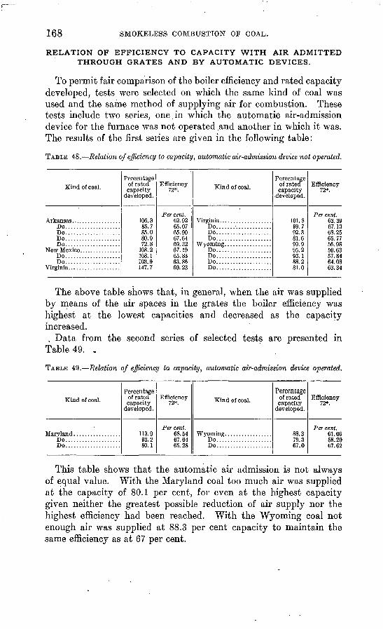
168 SMOKELESS COMBUSTION OF COAL.
RELATION OF EFFICIENCY TO CAPACITY WITH AIR ADMITTED THROUGH GRATES AND BY AUTOMATIC DEVICES.
To permit fair comparison of the boiler efficiency and rated capacity developed, tests were selected on which the same kind of coal was used and the same method of supplying air for combustion. These tests include two series, one.in which the automatic air-admission device for the furnace was not operated and another in which it was. The results of the first series are given in the following table:
TABLE 48. Relation of efficiency to capacity, automatic air-admission device not operated.
Kind of coal.
Do....................Do....................Do....................Do....................
Do....................Do....................
Virginia...................
Percentage of rated capacity
developed.
106.385.785.080.972.8
108.2108.1103.9147.7
Efficiency 72*.
Per cent. 62.9265.0765.9067.6469.3267.1965.8363.8660.23
Kind of coal.
Virginia...................Do....................Do....................Do....................
Do....................Do....................Do....................Do....................
Percentage of rated capacity
developed.
101.899.792.381.6QQ Q95.293.188.281.0
Efficiency 72*.
Per cent. 63.3967.1368.2565.7756.9859.6357.8464.0863.34
The above table shows that, in general, when the air was supplied by means of the air spaces in the grates the boiler efficiency was highest at the lowest capacities and decreased as the capacity increased.
. Data from the second series of selected tests are presented in Table 49. .
TABLE 49. Relation of efficiency to capacity, automatic air-admission device operated.
Kind of coal.
Do....................Do....................
Percentage of rated capacity
developed.
113.993.280.1
Efficiency 72*.
Per cent. 68.5467.6465.28
Kind of coal.
Wyoming. ................Do....................Do....................
Percentageof rated capacity
developed.
88.379.367.0
Efficiency 72*.
Per cent. 61.0658.2067.62
This table shows that the automatic air admission is not always of equal value. With the Maryland coal too much air was supplied at the capacity of 80.1 per cent, for even at the highest capacity given neither the greatest possible reduction of air supply nor the highest efficiency had been reached. With the Wyoming coal not enough air was supplied at 88.3 per cent capacity to maintain the same efficiency as at 67 per cent.
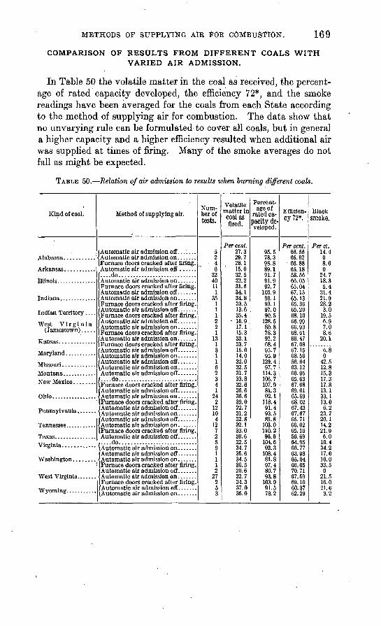
METHODS OF SUPPLYING AIR FOE COMBUSTION. 169
COMPARISON OF RESULTS FROM DIFFERENT COALS WITH VARIED AIR ADMISSION.
In Table 50 the volatile matter in the coal as received, the percent age of rated capacity developed, the efficiency 72*, and the smoke readings have been averaged for the coals from each State according to the method of supplying air for combustion. The data show that no unvarying rule can be formulated to cover all coals, but in general a higher capacity and a higher efficiency resulted when additional air was supplied at times of firing. Many of the smoke averages do not fall as might be expected.
TABLE 50. Relation of air admission to results when burning different coals.
Kind of coal.
Illinois.........'.....
Indian Territory ....
West Virginia (Jamestown) .....
Ohio................
Tcnn6ss6 6
Virginia............
West Virginia.......
Method of supplying air.
| Automatic air admission off .......
iFurnace doors cracked after firing.
f... .do...... ......................
(.Furnace doors cracked after firing.
IFurnace doors cracked after firing.
IFurnace doors cracked after firing.
(Furnace doors cracked after firing. /Automatic air admission on. ......(Furnace doors cracked after firing. /Automatic air admission off. ......\Automatic air admission on ....... | Automatic air admission off .......\Automatic air admission on .......
....do............................Furnace doors cracked after firing.
Furnace doors cracked after firing, f Automatic air admission off .......Automatic air admission on .......
iFurnace doors cracked after firing.
i....do............................\Automatic air admission on. ......
Furnace doors cracked after firing.
Furnace doors cracked after firing. /Automatic air admission off .......^Automatic air admission on .......
Num ber of tests.
5 2 4 6
32 40 11
1 35
1 1 1 2 2 1
13 1 3 1 1 6 2 3 4 1
24 2
12 10 4
12 7 2 5 9 1 1 1 2
27 2 5 3
Volatile matter in coal as fired.
Per cent. 27.3 29.7 28.1 15.0 32.5 32.2 31.6 34.1 34.8 33.5 13.6 35.4
16.9 17.1 15.3 33.1 33.7 15.0 14.0 32.0 32.5 31.7 33.8 32.6 36.6 36.6 39.0 22.7 31.2 32.8 32.1 33.0 30.6 22.5 34.7 35.6 34.5 36.5 20.6 32.7 34.3 37.0 35.0
Percent age of
rated ca pacity de veloped.
95.5 78.3 98.8 89.1 91.7 91.9 92.7
103.9 90.1 93.1 97.0 90.5
128.5 80.8 78.3 92.2 68.4 95.7 95.9
129.4 97.7
114.3 106.7 107.9 81.3 92.1
118.4 91.4 93.5 89.8
103.0 110.2 96.6
104.6 92.3
108.4 81.8 97.4 80.7 93.8
103.9 91.5 78.2
Efficien cy 72*.
Per cent. 66.56 65.92 66.88 65.18 58.56 66.05 65.04 67.15 65.13 65.36 65.20 68.10 66.99 66.93 68. 61 66.47 67.08 67.15 68.56 56.64 63.12 66.95 65.63 67.08 69.01 65.69 68.02 67.43 67.67 65.71 66.02 65.16 56.69 64.95 66.77 63.98 65.04 66.65 70.71 67.59 69.10 60.37 62.29
Blacksmoke.
Perct. 14.4
0 8.0 0
24.7 18.8 5.4
31.4 21.9 28.2 3.0
19.5 6.9 7.0 8.6
20.1
6.8 0
42.5 12.8 15.3 17.3 17.8 13.1 33.1 13.0 6.2
23.7 20.1 14.2 21.9 6.0
10.4 34.2 17.0 10.0 33.5
0 21.5 16.0 21.6 3.2
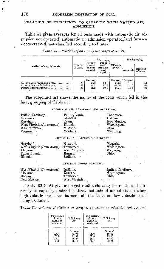
170 SMOKELESS COMBUSTION" OF COAL..
RELATION OF EFFICIENCY TO CAPACITY WITH VARIED AIRADMISSION.
Table 51 gives averages for all tests made with automatic air ad mission not operated, automatic air admission operated, and furnace doors cracked, not classified according to States.
TABLE 51. Relations of air supply to averages of results.
Method of supplying air. Number of tests.
88 185 35
Volatile matter in coal
as fired.
Per cent. 28.0 33.2 31.2.
Percent age of rated
capacity devel oped.
93.8 92.9 99.7
Efficien cy 72*.
Per cent. 62.95 66.06
' 66.21
Black smoke.
Amount.
Per cent. 11.8 21.6 15.4
Number of tests.
59 16228
The subjoined list shows the names of the coals which fell in the final grouping of Table 51:
AUTOMATIC AIR ADMISSION NOT OPERATED.
Indian Territory.Arkansas.Maryland.West Virginia (Jamestown).West Virginia..Virginia.
Pennsylvania. Alabama.
Illinois.Missouri.Montana.
Tennessee. Indiana. New Mexico. Washington. Ohio. Wyoming.
AUTOMATIC AIR ADMISSION OPERATED.
Maryland.West Virginia (Jamestown).Alabama.Pennsylvania.Illinois.
West Virginia (Jamestown).Alabama.Illinois.New Mexico.
Missouri. Tennessee'. West Virginia. Kansas. Indiana.
FURNACE DOORS CRACKED.
Indiana. Kansas. Tennessee. West Virginia.
Virginia. Washington. Wyoming. Ohio.
Indian Territory. Washington. Ohio.
.Tables 52 to 54 give averaged results showing the relation of effi ciency to capacity under the three methods of air admission when high-volatile coals are burned, all the tests on low-volatile coals being excluded.
TABLE 52. Relation of efficiency to capacity, automatic air admission not operated.
Percentage of ratedcapacity
developed.
108.4106.3105.398.0
Efficiency72*.
Per cent.63.9861.9766.3966.19
Percentage of ratedcapacity
developed.
96.695.586.480.7
Efficiency72*.
Per cent.56.6966.5664.6970.71
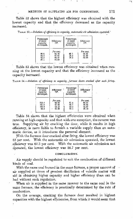
METHODS OF SUPPLYING AIR FOE COMBUSTION, 171
Table 52 shows that the highest efficiency was obtained with the lowest capacity and that the efficiency decreased as the capacity increased.
TABLE 53. Relation of efficiency to capacity, automatic air admission operated.'
Percentageof ratedcapacity
developed.
98.693.592.292.1
Efficiency 72*.
Per cent.05.7067.6766.4765.69
Percentageof ratedcapacity
developed.
88.178.378.2
Efficiency72*.
Per cent.65. 6565.9262.29
Table 53 shows that the lowest efficiency was obtained when run ning at the lowest capacity and that the efficiency increased as the capacity increased.
TABLE 54. Relation of efficiency to capacity, furnace doors cracked after each firing.
Percentage of ratedcapacity
developed.
118.4107.9103.998.8
Efficiency72*.
Per cent.68.0267.0869.10
66.88
Percentage of ratedcapacity
developed.
97.492.790.690.5
Efficiency72*.
Per cent.66.6565.0465.8768.10
Table 54 shows that the highest efficiencies were obtained when running at high capacity and that with one exception, the reverse was true. Supplying air by cracking the door, while it results in high efficiency, is more liable to furnish a variable supply than an auto matic device, as it introduces the personal element.
With the furnace door cracked after firing, the lowest efficiency was 65 per cent. With the automatic air admission operated, the lowest
.efficiency was 62.3 per cent. With the automatic air admission not operated, the lowest efficiency was 56.7 per cent.
CONCLUSIONS.
Air supply should be regulated to' suit the combustion of different kinds of coal.
With the same coal burned in the same furnace, a proper amount of air supplied at times of greatest distillation of volatile matter will aid in obtaining higher capacity and higher efficiency than can be had without such regulation.
When air is supplied in the same manner to the same coal in the same furnace, the efficiency is practically determined by the rate of combustion.
On the average, cracking the furnace door resulted in highest capacities with the highest efficiencies, from which it would seem that
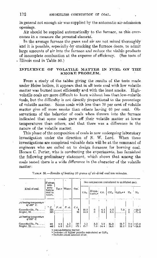
172 SMOKELESS COMBUSTION OF COAL.
in general not enough air was supplied by the automatic air-admission openings.
Air should be supplied automatically to the furnace, as this over comes in a measure the personal element.
In the average furnace the gases and air are not mixed thoroughly and it is possible, especially-by cracking the furnace doors, to admit large amounts of air into the furnace and reduce the visible products of incomplete combustion at the expense of efficiency. (See tests of Illinois coal in Table 50.)
INFLUENCE OF VOLATILE MATTER IN FUEL ON THE SMOKE PROBLEM.
From a study of the tables giving the results of the tests made under Heine boilers, it appears that in all tests coal with low volatile matter was burned most efficiently and with the least smoke. High- volatile coals are more difficult to burn without loss than low-volatile Coals, but the difficulty is not directly proportional to the percentage of volatile matter. Some coals with less than 30 per cent of volatile matter give off more smoke than others having 40 per cent. Ob servations of the behavior of coals when thrown into the furnace indicated that some coals gave off their volatile matter at lower temperatures than others, and that there was a difference in the nature of the volatile matter.
This phase of the composition of coals is now undergoing laboratory investigation under the direction of N. W. Lord. When these investigations are completed valuable data will be at the command of engineers who are called on to design furnaces for burning coal. Horace C. Porter, who is conducting the experiments, has furnished the following preliminary statement, which shows that among the coals tested there is a wide difference in the character of the volatile matter:
TABLE 55. Results of heating 10 grams of air-dried coal ten minutes.
Kind of coal.
At heating temperature 0/600° C.
Connellsville, Pa .....
At heating temperature 0/600° C.
Connellsville, Pa ..... Zeigler, 111............
Highest tem pera
ture in coal in retort.
0 C. 335 325
441440
Tar.o
P.ct.
4.9 6.8
Water.
P.ct.
3.2 13.0
Gas'.
C.c.8
90
190 173
Gas composition (calculated to undiluted gas).
C0 2 .
30.0 14.8
6.3 15.7
Illumi- nsvnts.o
0 0
8.2 7.0
CO.
6.5 5.3
5.9 14.4
CH4 .
6.5 8.0
36.9 19.0
C2H8.« b
7.0
23.7 22.2
Hi.
0 0
2.0 2.8
N2 .
c50.0 c?1.9
C17.0 cl8.9
n Smoke-forming matter.& Includes all higher paraffin calculated as Cjc Includes small amount of air.
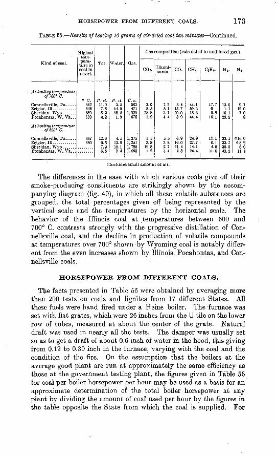
HORSEPOWER FROM DIFFERENT COALS. 173
TABLE 55. Results of heating 10 grams of air-dried coal ten minutes Continued.
Kind of coal.
At heating temperature of700° C.
Zeiglor, 111............
Pocahontas, W. Va...
At heatinq temperature 0/800° C.
Zeigler, 111............
Highest tem pera ture in coal in retort.
0 C.562 545 580 599
687 680
Tar.
P.ct. 11.0 7.8 8.2 4.2
12.6 9.3 7.9 6.5
Water.
P.ct. 3.5
14.0 18.5 1.9
4.5 13.9 19.1 2.4
Gas.
C.c.583 471
1,020 675
1,375 1,251 1,780 1,590
Gas composition (calculated to undiluted gas.)
COj.
3.0 8.5
28.8 1.9
1.5 3.8
19.8 1.2
Illumi- nants.
7.2 5.1 3.7 4.4
5.5 3.8 2.7 3.4
CO.
5.4 13.7 20.0 3.9
6.9 16.0 21.4 4.8
CH<.
44.1 59.6 18.6 44.4
24.9 27.7 14.1 24.4
CaH6 .
17.7 0 6.8
16.1
12.1 6.1 4.0
11.6
H8 .
13.5 1.1
15.1 28.5
33.1 33.7 30.0 43.2
Ni.
9.1 12.0
7.JO .8
ol6.0 o8.9
8.0 11.4
"Includes small amount of air.
The differences in the ease with which various coals give off their smoke-producing constituents are strikingly shown by the accom panying diagram (fig. 40), in which all these volatile substances are grouped, the total percentages given off being represented by the> vertical scale and the temperatures by the horizontal scale. The behavior of the Illinois coal at temperatures between 600 and 700° C. contrasts strongly with the progressive distillation of Con- nellsville coal, and the decline in production of volatile compounds at temperatures over 700° shown -by Wyoming coal is notably differ ent from the even increases shown by Illinois, Pocahontas, and Con- nellsville coals.
HORSEPOWER FROM DIFFERENT COALS.
The facts presented in Table 56 were obtained by averaging more than 200 tests on coals and lignites from 17 different States. All these fuels were hand fired under a Heine boiler. The furnace was set with flat grates, which were 26 inches from the U tile on the lower row of tubes, measured at about the center of the grate. Natural draft was used in nearly all the tests. The damper was usually set so as to get a draft of about 0.6 inch of water in the hood, this giving from 0.12 to 0.30 inch in the furnace, varying with the coal and the condition of the fire. On the assumption that the boilers at the average good plant are run at approximately the same efficiency as those at the government testing plant, the figures given in Table 56 for coal per boiler horsepower per hour may be used as a basis for an approximate determination of the total boiler horsepower at any plant by dividing the amount of coal used per hour by the figures in the table opposite the State from which the coal is supplied. For
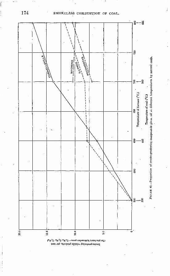
20.0
~
15.0
10.0
WY
OM
ING
11 Is-
5.0
500
330
550
600
440
650
.700
Tem
pera
ture
of
furn
ace
(°C
.)75
0
565
Tem
pera
ture
of
coal
(°C
.) FI
GU
RE
40.
Pro
port
ion
of
smok
e-pr
oduc
ing
com
poun
ds g
iven
off
at
diff
eren
t te
mper
ature
s by s
ever
al c
oals
.
800
685
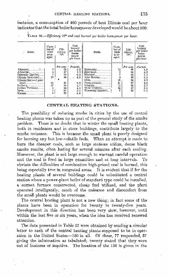
CENTRAL HEATING STATIONS. 175
instance, a consumption of 460 pounds of best Illinois coal per hour indicates that the total boiler horsepower developed would be about 100.
TABLE 56. Efficiency 72* and coal burned per boiler horsepower per hour.
, State.
Colorado (lignite)....
Num ber of tests aver aged.
341
23
2127
4
8
Effi ciency,
72*.
Per cent. 666761'66
*
6163646163"
Coal burned
per boiler horse power
per hour.
Pounds.d 9
3.96.0
,- 4.6
5.0
5.54.4
State.
Missouri .............New Mexico.........Ohio.................
Virginia..............
Num ber of tests aver aged.
13372
262112
8
Effi ciency,
72*.
Per cent. 656663606467656759
Coal burned
per boiler horse power
per hour.
Pounds. 4.03.85.15.54.2^ fi3 7
3.G6.1
CENTRAL HEATING STATIONS.
The possibility of reducing smoke in cities by the use of central heating plants was taken up as part of the general study of the smoke problem. There is no doubt that in winter the small heating plants, both in residences and in store buildings, contribute largely to the smoke nuisance. This is because the small plant is poorly designed for burning any but low-volatile fuels. When an attempt is made to burn the cheaper coals, such as large stations utilize, dense black smoke results, often lasting for several minutes after each coaling. Moreover, the plant is not large enough to warrant careful operation and the coal is fired in large quantities and at long intervals. To obviate the difficulties of combustion high-priced coal is burned, this being especially true in congested areas. It is evident that if for the heating plants of several buildings could be substituted a central station where a power-plant boiler of standard type could be installed, a correct furnace constructed, cheap fuel utilized, and the plant operated intelligently, much of the nuisance and discomfort from the small plants would be overcome.
The central heating plant is not a new thing; in fact some of the plants have been in operation for twenty to twenty-five years. Development in this direction has been very slow, however, until within the last five or six years, when the idea has received renewed attention.
The data presented in Table 57 were obtained by sending a circular letter to each of the central heating plants supposed to be in oper ation in the United States 150 in all. Of these, 77 responded, 57 giving the information as tabulated; twenty stated that they were out of business or inactive. The location of the 130 is given in the
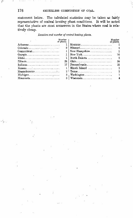
r
176 SMOKELESS COMBUSTION OF COAL.
statement below. The tabulated statistics may be taken as fairly representative of central heating plant conditions. It will be noted that the plants are most numerous in the States where coal is rela tively cheap.
Location and number of central heating plants.
Idaho..............
Kansas. .............
Minnesota... .......
Number of plants.
............. 1............ 2............ 1............ 1............ 1
24............ 17............ 1
2............ 3............ 3
Montana ..............Missouri. ..............New Hampshire .......New York....... ......North Dakota .........Ohio..................Pennsylvania. .........Rhode Island .........
Wisconsin.. ...........
Number of plants.
......... 14
......... 1
......... 10
......... 2
......... 24
......... 25
......... 1
......... 1
......... 1
......... 4
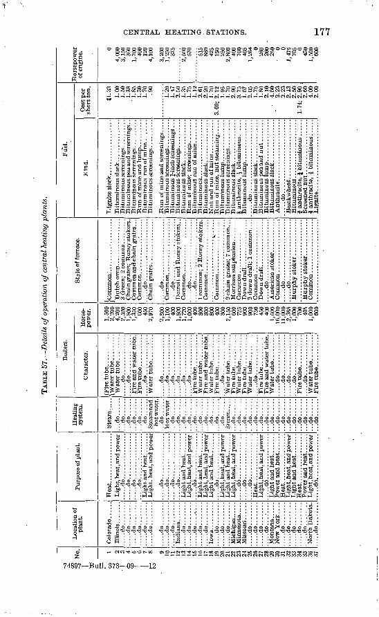
TAB
LE 5
7.
Det
ails
of o
pera
tion
of c
entr
al h
eati
ng p
lants
.
No. 1 2 3 4 5 6 7 8 9 10
11
12
13
14
15
16
17
18
19
20
21
22
23
24
25
26
27
28
29
30
31
32
33
34
35
36
37
Lo
cati
on
of
pla
nt.
.....d
o........
....
.do..
....
....
...d
o..
....
....
...d
o..
....
....
...d
o..
....
....
...d
o..
....
..
....
.do
....
....
....
.do..
....
....
...d
o..
....
..
....
.do..
....
....
...d
o..
....
.......d
o.........
....
.do..
....
....
...d
o..
....
..
....
.do
....
....
....
.do..
....
....
...d
o..
....
..
....
.do
....
....
....
.do..
....
....
...d
o..
....
..
.....d
o.........
New
York
....
....
.do
....
....
....
.do..
....
....
...d
o..
....
....
...d
o..
....
....
...d
o..
....
..N
orth
Dak
ota.
..
...d
o..
....
..
Pur
pose
of p
lant
.
Lig
ht, h
eat,
and
pow
er
.....d
o................
.....d
o................
.....d
o...............
Lig
ht, h
eat,
and
pow
er
.....d
o................
.....d
o...........
......d
o...............
.....d
o................
Lig
ht, h
eat,
and
pow
er
.....d
o................
Lig
ht, h
eat,
and
pow
er
Lig
ht, h
eat,
and
pow
er
Lig
ht, h
eat,
and
pow
er
.....d
o................
.....d
o................
.....d
o................
Heat.
....
....
....
....
.L
ight
, hea
t, an
d po
wer
.....d
o................
Heat.
....
....
....
....
.L
ight
, hea
t, an
d po
wer
Hea
t. .................
Lig
ht, h
eat,
and
pow
er
.... .d
o. ...
....
....
....
Hea
ting
sy
stem
.
Ste
am..
...
...d
o......
...d
o......
...d
o......
...d
o......
...d
o......
...d
o......
Stea
m a
nd
hot w
ater
. ...d
o......
...d
o......
...d
o......
...d
o......
...d
o:.
....
...d
o......
...d
o......
...d
o......
...d
o......
...d
o......
...d
o......
Ste
am..
...
...d
o......
...d
o......
...d
o......
...d
o......
...d
o......
...d
o......
...d
o......
...d
o......
...d
o......
...d
o......
...d
o......
...d
o......
...d
o......
...d
o......
...d
o......
...d
o......
Boi
lers
.
Cha
ract
er.
(Tir
e tu
be...........
\\V
ater
tube.
...
....
.
.....d
o..............
....
.do
..............
Fir
e an
d w
ater
tub
e.
.....d
o..............
.....d
o..............
....
.do
....
....
....
....
...d
o..
....
....
....
....
.do
....
....
....
.......d
o..............
.....d
o..............
Fir
e an
d w
ater
tube
.
.....d
o.............
.....d
o..............
Fir
e an
d w
ater
tub
e.
....
.do
....
....
....
....
...d
o..
....
....
....
....
.do
....
....
....
....
...d
o..
....
....
....
....
.do
....
....
....
..
Fir
e tu
be... ..
....
..
Hor
se
pow
er.
1,50
0 2,
200
4,20
0 2,
520
1,80
0 1,
350
600
450
2,97
0
2Q
AA
1,10
0 40
0 1,
800
1,72
0 1,
000
400
800
800
800
400
300
2,15
0 60
0 72
5 90
0 90
0 75
0 45
0 40
0 1,
500
16,0
00
11,0
002,
368
1,60
0 70
0 40
5 1,
000
600
Sty
le o
f fu
rnac
e.
Cha
ingr
ates
; R
oney
stok
ers.
C
omm
on a
nd c
hain
gra
tes.
. .
....
.do
....
....
....
....
....
..
.....d
o......................
.....d
o......................
Det
roit
and
Ron
ey s
toke
rs. .
.....d
o......................
.....d
o......................
1 co
mm
on;
2 H
oney
sto
kers
.
2 ch
ain
grat
es;
7 co
mm
on. .
.
....
.do
....
....
....
....
....
..
....
.do
....
....
....
....
....
....
...d
o..
....
....
....
....
....
Fue
l.
Kin
d.
Bit
umin
ous
pea
and
scre
enin
gs. .
Bit
umin
ous
£-m
cn s
cree
ning
s . .
. B
itum
inou
s sc
reen
ings
..........
.....d
o..........................
Lig
nit
e........................ .
Cos
t per
sh
ort t
on.
81.3
31.
00
1.50
1.
38
1.85
1.
30
1.70
.9
0
i.20
1.47
2.
50
1.35
1.
75
1.12
2.
61
2.2
0
1.70
3.
00;
2.1
2
1.95
1.
70
2.90
3.
75
1.67
2.
05
1.75
1.
80
2.1
0
4.60
2.
23
2.23
2
.13
2.5
0
1.74
; 2
.90
2
.60
4.
00
2.0
0
Hors
epow
er
of e
ngin
e.
04,
000
3,15
0 30
0 1,
700
400
120
4,10
0
3,20
0 1,
250
375
2,50
0 57
0
515
880
425
150
250
2,80
0 40
0 70
0 40
5 1,
264 0
280
200
250 0 0
1,47
5 70
5 0 43
0 1,
500
600
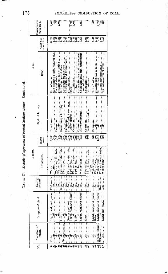
TAB
LE 5
7.
Det
ails
of
oper
atio
n o
f ce
ntra
l he
atin
g pla
nts
Con
tinu
ed.
No. 38 39 40 41 4?:
43 44 45 4fi
47 48 49 50 51 52 53 54 55 56 57
plan
t.
Ohio
....
....
.......d
o........
....
.do
....
....
....
.do
....
....
....
.do
....
....
.....d
o........
.....d
o........
.....d
o........
.....d
o........
.....d
o........
.....d
o........
....
.do
....
....
.....d
o........
.....d
o........
.....d
o........
Rho
de I
slan
d.
.....d
o........
Purp
ose
of p
lant
.
.....d
o................
.....d
o................
.....d
o................
Hea
t. ..
....
....
....
...
.....d
o................
.....d
o................
.....d
o................
Hea
t. .................
....
.do
....
.:..
....
....
Heat.
....
....
....
....
.L
ight
, hea
t, an
d po
wer
.....d
o. ...............
syst
em.
...d
o......
...d
o......
...d
o......
...d
o......
...d
o..
....
...d
o......
...d
o......
...d
o......
...d
o......
...d
o......
...d
o..
....
...d
o..
....
...d
o......
...d
o..
....
...d
o..
....
...d
o..
....
...d
o..
....
Boi
lers
.
Cha
ract
er.
.....d
o..............
....
.do
..............
tube
.
Wat
er t
ube.
........
Hor
se
pow
er.
2,80
01,
400
1,10
095
01,
200
1,60
01,
700
1,55
01,
500
1,40
01,
200
1,00
095
0
900
725
600
600
3,31
560
060
0
Styl
e of
fur
nace
.
.....d
o......................
.....d
o......................
....
.do..
....
....
....
....
....
....
.do..
....
....
....
....
....
.....d
o......................
Fuel
.
Kin
d.
Qla
nb
-
.. ...
do
....
... ...................
run o
f m
ine.
Cos
t p
er
sho
rt t
on.
82.2
01.
30i
^n2.
251.
75i
^n2.
282.
751
002.
591.
031.
142.
63
1.03
2.77
1.38
1 *?
7
3.75
2C
A
of e
ngin
e.
3,00
055
07
VI
1,00
0 0 0 0
1 9A
ft
1,05
0 0 01,
050 0 0
OA
A 04,
250
800
800
00
CO CO o
O & to)
d CO H
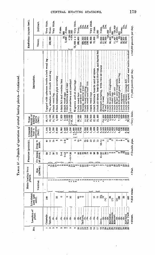
TAB
LE 5
7.
Det
ails
of
oper
atio
n of c
entr
al h
eati
ng p
lants
Conti
nued
.
No. 1 2 3 4 5 6 7 S 9 10
11
12
13
14 15
16
17 18
19
20
21
22
23
24
25
26
27
28
29
30
Loc
atio
n of
pla
nt.
.....d
o........
.....d
o.........
.....d
o........
.....d
o........
.....d
o........
.....d
o........
.....d
o........
.....d
o........
.....d
o........
India
na.......
.....d
o........
.....d
o........
.....d
o........
.....d
o........
.....d
o........
Iow
a..........
....
.do
....
....
.....d
o........
.....d
o........
Mic
hig
an.
Min
nes
ota
....
.
.....d
o........
....
.do
....
....
. ..
...d
o..
....
...
....
.do
....
....
.M
onta
na.
.....
New
Yo
rk.....
Liv
e st
eam
us
ed (
per
cent
). 100 33
0 0 50 65 0 0 16
15 33J
75
O
66
(/)
(0) 10
0 50 ioo
Mai
ns l
eadi
ng f
rom
p
lan
ts.
Num
ber.
< i
\ < j
f o
l 1
61
/ o
l {
"1 6 1 1 2 2
{ i cl
f cl
\ °1 cl 1 1 2 1 1 2 1
. .7
1 8 3
Size
(i
nche
s). 8 12
20
10
6 5 8 8 8 16
12
12 8 7
' 10
20
12
10
7 6 12 6 7 8 7 5
- 12
10
8 16
12
10 6 10
12
15
Pre
ssur
e (p
ou
nd
s).
On
mai
ns
at p
lan
t. 50
} » 20
i W
| 3-
66-
15 2
| o
g-6
50 6 60
88
30
48
70
| 40
50
|
6045
-60 51
30
17
3 5 3 * 5 1J
5J
10
95
Dro
p in
m
ain
. 42
12
15 6 2
1-3 i 6 10
9 20
40 10
25
1510
-15 8 15 o4 0 1 0 1 i
10
Gre
ates
t d
ista
nce
h
eat
is
conv
eyed
(f
eet;
.
7,55
0,
3,96
0 7,
200
2; 0
00
3,96
02,
640
1,30
05,
280
1 o3,0
00
\ 66
,600
7,
920
2,64
0
3,96
0 4,
500
5,28
0 1,
500
5,00
03,
520
3,00
0 2,
000
4,50
0 1,
300
1,60
0 1,
072
400
4,60
0 13
0 40
0 2,
000
3,20
0
Tot
al
leng
th o
f hea
ting
mai
ns
(fee
t).
38, 1
73
10,5
60
14,7
84"
4,00
0
7,92
02,
640
4,00
0 ( o
15,
840
\
6 31
, 680
58,0
80
17,5
00
10, 5
60
34,0
0015
/840
12
,000
18
,480
d8,8
00
4,00
0 12
,000
4,
000
3,96
0 1,
460
700
7,92
0 60
0 70
0 4,
000
29,0
40
Insu
lati
on
.
5-in
ch a
ir s
pace
; b
oar
ds
and s
havi
ngs,
an
d ta
rred
felt
Woo
d ..
....
....
....
....
....
....
....
....
....
....
...
1-in
ch a
ir s
pace
: 4
-in
ch m
iner
al w
ool
insi
de c
onduit
Rad
iati
on
(sq
uar
e fe
et).
Dir
ect.
200,
000 35
, 2,
000
f ois
c I
627C
75, 0
00 x
2
100,
000
400,
000
120,
000
13
0, 0
0060
,000
70
,000
H
i85
,000
.
61,0
00
20,0
00
13S
50,0
00
30,
11, 4
81
4,90
0 83,
33,0
00
38,2
67
70,0
00
Indir
ect.
Ver
y li
ttle
. N
one.
Ver
y li
ttle
.
Non
e.00
0 Non
e.,0
00
,000 Ver
y li
ttle
.N
one.
D
o.
Do.
D
o.
Do.
Ver
y li
ttle
. N
one.
,0
00 Non
e.
Do.
D
o.
,000
N
one.
00
0 150,
460
Non
e.
082 Non
e.
Do.
D
o.
O O
!z| CD
o S
team
.6
Hot
wat
er.
d D
oubl
e pi
pe.
Ver
y li
ttle
./
75,0
00 p
ounds
per
day.
g 14
6,00
0 p
ou
nd
s per
day
.
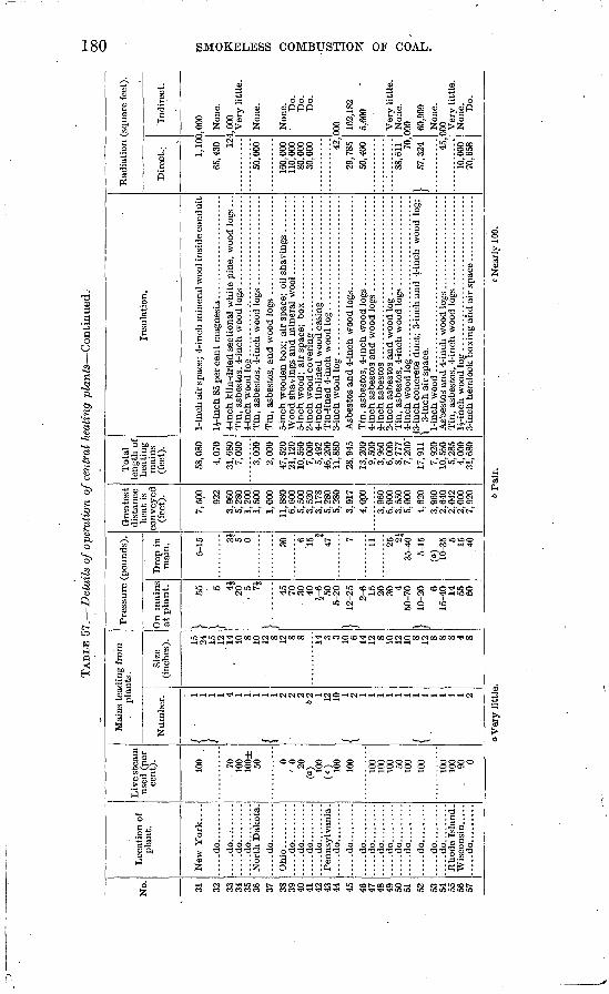
.TA
BLE
57
. D
etai
ls o
f ope
rati
on o
f cen
tral
hea
ting
pla
nts
Con
tinu
ed.
No. 31 32 33
34
35
36 37 38
39
40
41
42
43
44 45 46
47
48
49
50
51 52 53
54
55
56
57
Loc
atio
n of
p
lan
t.
New
York
. . .
.
....
.do..
....
...
....
.do..
....
...
....
.do..
....
...
....
.do..
....
...
Nort
h D
akot
a.
....
.do..
....
...
....
.do..
....
...
.....d
o.........
.....d
o.........
.....d
o.........
Pen
nsy
lvan
ia.
.....d
o.........
.....d
o.........
.....d
o.........
.....d
o.........
.....d
o.........
....
.do..
....
...
....
.do..
....
...
.....d
o.........
.....d
o.........
....
.do..
....
...
Rhode
Isla
nd
. W
isco
nsin
. ....
.....d
o.........
Liv
e st
eam
us
ed (
per
ce
nt). 100 70
10
0 10
0±
50 0'
0 20
(°) 10
0(c
) 100
100
100
100
100 50
100
100
100
100
. 90
0
Mai
ns l
eadi
ng f
rom
pl
ants
.
Num
ber.
i j 4 1 1 1
{ ! 2 2 2
621 12
10
{ ! i i i i
{. | i i i 2
Size
(i
nche
s). 15
24
15
12
,
14
10 8 10
12 8 12 8 8 14 3 3 10 6 14
12 8 10
12
10 8 12 8 8 8 4 8
Pre
ssure
(po
unds
).
On
mai
ns
at p
lant.
} ' »
} 4J
20
5 71
Y70
30
40
5-
6 50
5-20
| 12
-25
2-6 15
20
30
4 50
-70
| 10
-20 6
15-4
0 14
55
60
Dro
p in
m
ain. 5-15 31
5 0 30 6
"15 i
47 7 11 25 2J
35-4
05-
15(«
) 10
-35 5 15
40
Gre
ates
t d
ista
nce
h
eat
is
conv
eyed
(f
eet)
.
7,50
0
922
3,96
0 5,
280
1,20
0 1,
500'
1,00
011
,880
6,
600
5,50
0 3,
520
3,17
8 5,
280
5,28
03,
917
4,00
0
3,96
0 6,
000
3,55
0 5,
000
4,62
03,
960
2,64
0 2,
042
2,00
0 7,
920
To
tal
leng
th o
f h
eati
ng
m
ains
(f
eet)
.
58,0
80
4,07
031
,680
7,
000
3,00
0 2,
000
47, 5
20
21, 1
20
10. 5
60
7,00
0 5,
492
46,2
00
11,8
8028
, 945
13, 2
00
9,50
0 3,
960
6,00
08,
777
7,20
0'17
,911
7,92
0 10
,560
5,
285
4,00
0 31
,680
Insu
lati
on.
1-in
ch a
ir s
pace
; 4-
inch
min
eral
woo
l in
side
conduit
4-in
ch k
iln-
drie
d se
ctio
nal
whit
e pi
ne,
woo
d lo
gs .
. .
1-in
ch a
sbes
tos ..
....
....
....
....
....
....
..........
/3-i
nch
conc
rete
duct
; 3-
inch
and 4
-inc
h w
ood
log;
\
3-in
ch a
ir s
pace
.
Rad
iati
on
(sq
uare
fee
t).
Dir
ect.. 1,
1(X
65, 4
30 12
50,0
00
160,
000
110,
000
80,0
00
30,0
00 42,
29,7
85
50,4
00
88,61
1 70,
} 57
, 324 45
,
10,0
00
70,6
58
Indir
ect.
),000 Non
e.1,
000
Ver
y li
ttle
.
Non
e.
Non
e.
Do.
D
o.
Do.
300 16
2,18
2 5,
600
Ver
y li
ttle
. N
one.
00
0 60,9
09N
one.
00
0 Ver
y li
ttle
. N
one.
D
o.
00 o
o V
ery
litt
le.
6 P
air.
Nea
rly
100.
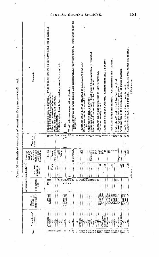
TAB
LE 5
7.
Det
ails
of
oper
atio
n of c
entr
al h
eati
ng p
lants
Conti
nued
.
No. 1 2 3 4 5 6 7 8 9 10 11
12
13
14 15
16
17
18
19
20
21
22
23
24
25
26
27
28
29
,3
0 31
32 m
Loc
atio
n of
pl
ant.
Illi
nois
........
do
Spac
e in
bu
ildin
gs
(cub
ic f
eet)
.
700,
000
1,20
0,00
0
.....d
o.........
..............
.....d
o.........
..............
. do
..
...
'-......d
o.........
.....d
o.........
.....d
o.........
.....d
o.........
.....d
o.........
.....d
o...
....
......d
o.........
.....d
o.........
.....d
o.........
.....d
o.........
.....d
o.........
....
.do
....
....
......d
o.........
.....d
o.........
.....d
o.........
....
.do
....
....
. ..
...d
o..
....
...
....
.do
....
....
...
...d
o..
....
...
.....d
o.........
/ 09
,000
,000
\
69,4
50,0
00
10,0
00,0
002,
389,
900
3,77
1,51
5 3,
634,
365
5,39
1,29
5 1,
650,
000
2,20
4,61
2 7,
777,
000
100,
000
, 000
15
, 500
, 000
10
-0n°
000
Ave
rage
pri
ce o
f hea
ting
.
Per
squ
are
foot
. SO. 6
5 .2
4
.25
.28
a. 2
5 6.1
5
{ 1-3
,1.1
5
.20
.20
.18
.15£
.1
2J
.15
.17
.18
.20
.15
""""."
25
"
.60
Per
1,0
00
poun
ds o
f w
ater
.
SO. 4
5
j.. ..
....
...
J }
.50
.60
.56
.50
.50
.42*
Ave
rage
co
st p
er
year
for
re
pair
s on
m
ains
, tun
ne
ls,
and
insu
lati
on.
SI, 5
00
Non
e.
Ver
y sm
all.
S100
N
one.
......
....
..
10 p
er c
ent.
3400
5 per
cen
t. S3
00
81
00
S359
S1
50
S6 325 0 0 0
Ver
y sm
all.
Smal
l. 31
75
Yea
rs i
n op
erat
ion. 26
12
3 7 5 2 1
o!7
i
656i
6 7 5 5 5 7 5 10 7 6 5 15 3 8 5 4 7 15
10 7 25 10
28
Rem
ark
s.
Con
dens
atio
n lo
ss,
12 p
er c
ent.
P
rice
to
larg
e de
aler
s, 8
2 pe
r 1,
000
cubi
c fe
et o
f con
tent
s.
34 p
er 1
,000
cub
ic f
eet o
f con
tent
s.
Liv
e st
eam
one
- ten
th o
f sea
son.
R
adia
tion
dir
ect
and
indi
rect
. D
irec
t sys
tem
. P
rofi
tabl
e w
hen
heat
is
furn
ishe
d as
a s
econ
dary
pro
duct
.
| D
o.
Wou
ld a
dvis
e co
ncen
trat
ion
of m
ains
.W
ould
adv
ise
use
of la
rger
mai
ns;
also
con
cent
rati
on o
f te
rrit
ory
heat
ed.
Insu
lati
on c
ould
be
impr
oved
.
Pro
fita
ble
whe
n he
at is
fur
nish
ed a
s a
seco
ndar
y pr
oduc
t. C
harg
e to
o lo
w f
or s
ucce
ssfu
l op
erat
ion.
D
o.
Con
dens
atio
n lo
ss,
5 pe
r ce
nt.
Rad
iati
on m
ostl
y di
rect
. H
eat s
houl
d be
aut
omat
ical
ly r
egul
ated
. M
ains
sho
uld
not e
xten
d, t
oo f
ar f
rom
pla
nt.
Pro
fita
ble
whe
n ex
haus
t st
eam
is
used
for
hea
ting
. R
adia
tion
mos
tly
dire
ct.
Rad
iati
on d
irec
t an
d in
dire
ct.
Con
dens
atio
n lo
ss,
6 pe
r ce
nt.
Rad
iati
on d
irec
t an
d in
dire
ct.
Con
dens
atio
n lo
ss 1
per
cen
t.
Mai
ns s
houl
d no
t ex
tend
too
far
fro
m p
lant
. 88
,000
,000
pou
nds
stea
m s
old
per
year
. O
ver
one-
half
of
the
stea
m i
s so
ld f
or p
ower
pur
pose
s.
Pro
fita
ble
whe
n ex
haus
t st
eam
is u
sed.
C
onde
nsat
ion
loss
. 3
to 6
per
cen
t. R
adia
tion
bot
h di
rect
and
ind
irec
t.
f W O W H O * W
o S
team
.b H
ot
wat
er.
OO
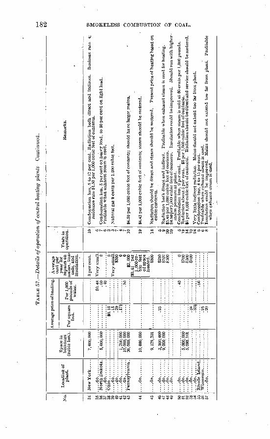
TAB
LE 5
7.
Det
ails
of o
pera
tion
of c
entr
al h
eati
ng p
lan
ts C
onti
nued
.
No. 34 35
36
37
38
39
40
41
42
43 44 45 46 47
48
49 50
51
52
53
54
55
56
57
Loc
atio
n of
pl
ant.
New
Yo
rk..
....
.....d
o.........
Nor
th D
akot
a.
.....d
o.........
Ohi
o ..........
.....d
o.........
.....d
o.........
....
.do..
....
...
.....d
o. ........
Pen
nsyl
vani
a .
.....d
o.........
.....d
o.........
....
.do..
....
...
.....d
o.........
.....d
o.........
.....d
o.........
....
.do..
....
...
.....d
o.........
....
.do
....
....
...
...d
o..
....
...
....
.do..
....
...
Rho
de I
slan
d.
.....d
o.........
Spac
e in
bu
ildi
ngs
(cub
ic f
eet)
.
7, 0
00, 0
00
5,00
0,00
0
1. 2
00, 0
00
10, 0
00, 0
00
26,0
00,0
00
10,0
00,0
00
3, 3
60, 0
00
5,00
0,00
0
Av
erag
e pri
ce o
f hea
ting.
Per
squar
e fo
ot.
............
SO. 1
5 .1
5
.20
.17
|
.25
.34
33J
.25
.20
Per
1,0
00
pounds
of
wat
er.
$0.4
8 .6
0
.40
.50
.40
.66
Aver
age
cost
per
year
for
repai
rs o
n
mai
ns,
tu
n
nel
s, a
nd
insu
lati
on
.
3 per
cent.
Ver
v s
mal
l.
0 0 V
ery
sm
all.
$3
00 0 0
$2, 0
00
80.4
1 per
1,
000
cu
bic
fe
et
of
spac
e heate
d.
$300
$250
$7
02
8500 0
$700
$5
00
$100
Yea
rs i
n
op
erat
ion
.
10 6 7 6 3 5 7 4 7 10 19 14 5 9 20
20 5 19
14
10
24 6 6 8
Rem
arks.
Co
nd
ensa
tio
n l
oss,
5 t
o 1
2 per
cen
t. R
adia
tion b
oth
dir
ect
and in
dir
ect.
B
usi
nes
s ra
te
4;
resi
den
ce r
ate
$4.5
0 per
1,0
00 c
ubic
fee
t of
co
nte
nts
.
Conden
sati
on l
oss,
5 p
er c
ent
on h
eavy l
oad
, to
50
per
cen
t on l
ight
load
. P
rofi
table
when
ex
hau
st s
team
is
use
d.
Nat
ura
l ga
s 9
cents
per
1,00
0 cu
bic
fee
t.
$4.5
0 p
er 1
,000
cu
bic
fee
t of
co
nte
nts
; sh
ould
hav
e la
rger
mai
ns.
34.4
3 per
1,0
00 c
ubic
fee
t of
co
nte
nts
; st
eam
should
be
met
ered
.
Rad
iati
on s
hould
be
dir
ect
and s
team
should
be
met
ered
. P
rese
nt p
rice
of
hea
tin
g b
ased
on
cubic
co
nte
nts
.
Rad
iati
on b
oth
dir
ect
and
in
dir
ect.
P
rofi
table
wh
en e
xhau
st s
team
is
use
d f
or h
eati
ng
. $5
.45
per
1,0
00 c
ubic
fee
t of
conte
nts
. $4.5
0per
l,000 c
ubic
fee
t of
conte
nts
. In
sula
tion c
ould
be
impro
ved
. S
hould
run w
ith h
igher
st
eam
pre
ssu
re a
t pla
nt.
C
on
den
sati
on
los
s, 9
per
cen
t.
Pro
fita
ble
when
ste
am i
s so
ld a
t 60
cen
ts p
er 1
,000
po
un
ds.
R
adia
tion a
bout
5 per
cen
t.
$5 p
er 1
,000
cubic
fee
t of
co
nte
nts
. $6
per
1,0
00 c
ub
ic f
eet
of c
onte
nts
. R
adia
tio
n s
ho
uld
be
dir
ect an
d s
erv
ice
sho
uld
be
met
ered
.
Ver
y l
ittl
e in
dir
ect
radia
tion.
Mai
ns s
hould
not
exte
nd
too
far
fro
m p
lant.
C
on
den
sati
on
los
s, 4
to 1
5 p
er c
ent.
P
rofi
tab
le w
hen
ex
hau
st s
team
is
use
d.
Insu
lati
on c
ould
b
e im
pro
ved
. M
ains
should
not
exte
nd t
oo
far
from
, pla
nt.
P
rofi
tab
le
when
ex
hau
st s
team
is
use
d.
oo
to
CENTRAL HEATING STATIONS. 183
Of the 57 plants included in Table 57 only 12 were operating for the express purpose of central heating. The remaining 45 were supplying either light and heat, power and heat, or power, light, and heat. Steam heat is furnished by 38 plants, hot water by 17, and a combination of steam and hot water by 2. The plants which have been installed in the last five or six years show about an equal propor tion of steam and hot-water heating. The plants range in size from 300 to 16,000 horsepower; only 25 per cent are of 600 horsepower or less. Sixteen of the plants have mechanical stokers. The price of coal ranges from $4.60 per short ton in Montana to 90 cents in Illinois, the average cost from all the plants being $2.05 per short ton. Both direct and indirect radiation are used, but by far the greater propor tion is direct. The greatest distance to which heat is sent from the station varies considerably, but a reasonable distance seems to be about 4,000 to 5,000 feet.
Payment for the use of steam is made in two ways (1) at a flat rate, based on square feet of radiating surface installed or on 1 ;000 cubic feet of contents heated, or (2) at a meter rate, based on 1,000 pounds of condensed steam. The price paid per square foot of radi ating surface averaged 33£ cents, and varied from 22£ to 65 cents. The plants selling on a basis of 1,000 cubic feet of contents charged an average of $4.46, the price varying from $2 to $6. On the basis of 1,000 pounds of condensed steam the payments averaged 50£ cents, ranging from 40 to 66 cents. One plant that sold heat on this basis for 40 cents intimated that such a rate was not profitable.
The hot-water plants sold heat only on the basis of square feet of radiating surface installed, the average rate being 17£ cents and the range from 12£ to 25 cents per square foot. Two plants, one selling at 12£ and the other at 15£ cents, claimed that their prices were too low for successful operation.
A comparison of the prices charged by central stations, as given in Table 57, with the cost of fuel only for a house-heating boiler, as published in Bulletin 366,a shows that in many cases the cost of pro ducing heat on the premises equals the price charged by the central station. When heat is purchased the customer avoids the annoyance of having to supervise the operation of the heating plant, as well as the dust resulting from the delivery of fuel and the removal of ashes. Some allowance should also be made for the space that would be occupied by the heater and for the expense necessary to install and keep a boiler in repair.
The following suggestions have been made by the managers of the plants and are worthy of consideration:
Heat from a central plant should be, as largely as possible, a secondary product.
«llandall, D. T., Tests of coal and briquets as fuel for house-heating boilers: Bull. U. S. Geol. Survey No. 366, 1908, p. 39.
184 ' SMOKELESS-COMBUSTION OF COAL.
Heating mains should be concentrated and should not extend too far from the station.
Direct radiation should be installed.Mains should be of sufficient size to avoid the necessity of high
pressure at the station.Heat should be under automatic control.The flat rate is not a successful basis for payment; the service
should be metered.
GENERAL CONCLUSIONS ON SMOKE ABATEMENT.
Some general conclusions from the facts set forth in this volume are as follows:
The flame and the distilled gases should not be allowed to come into contact with the boiler surfaces until combustion is complete.
Fire-brick furnaces of sufficient length and a continuous or nearly continuous supply of .coal and air to the fire make it possible to burn most coals efficiently and without smoke.
Coals containing a large percentage of tar and heavy hydro carbons are difficult to burn- without smoke and require special furnaces and more than ordinary care in .firing.
Briquets are suitable for use under power-plant conditions when burned in a reasonably good furnace at the temperatures at which, such furnaces are usually operated. In such furnaces briquets, generally give better results than the same coal burned raw.
In ordinary boiler furnaces only coals high in fixed carbon can. be burned without smoke, except by expert firemen using more thani ordinary care in firing.
Combinations of boiler-room equipment suitable for nearly all power-plant conditions can be selected, and can be operated without objectionable smoke when reasonable care is exercised.
Of the existing plants some can be remodeled to advantage. Others can not, but must continue to burn coals high in fixed carbon or to burn other coals with inefficient results, accompanied by more or less annoyance from smoke. In these cases a new, well-designed plant is the only solution of the difficulty.
Large plants are for obvious reasons usually operated more eco nomically than small ones, and the increasing growth of central plants offers a solution of the problem of procuring heat and power at a reasonable price and without annoyance from smoke.
The increasing use of coke from by-product coke plants in sections where soft coal was previously used, the use of gas for domestic pur poses, and the purchase of heat from a central plant in business and. residence sections all have their influence in making possible a clean, and comfortable city.
SMOKELESS COMBUSTION OF COAL. 185
BIBLIO GRAPHY.
SURVEY PUBLICATIONS ON COAL AND FUEL TESTING.
A classified list of Survey papers dealing with coal is given in Bulle tin 316, and in an abstract from that bulletin, pp. 439 to 532, pub lished separately.
The following publications on fuel .testing, except those to which a price is affixed, can be obtained free by applying to the Director, Geological Survey, Washington, D. C. The priced publications can be purchased from the Superintendent of Documents, Government Printing Office, Washington, D. C.
BULLETIN 261. Preliminary report on the operations of the coal-testing plant of the United States Geological Survey at the Louisiana Purchase Exposition, in St. Louis, Mo., 1904; E. W. Parker, J. A. Holmes, M. R. Campbell, committee in charge. 1905. 172pp. 10 cents.
. PROFESSIONAL PAPER 48. Report on the operations of the coal-testing plant of the United States Geological Survey at the Louisiana Purchase Exposition, St. Louis, Mo., 1904; E. W. Parker, J. A. Holmes, M. R. Campbell, committee in charge. 1906. In three parts. 1492 pp., 13 pis. $1.50.
BULLETIN 290. Preliminary report on the operations of the fuel-testing plant of the United States Geological Survey at St. Louis, Mo., 1905, by J. A. Holmes. 1906. 240 pp. 20 cents.
BULLETIN 323. Experimental work conducted in the chemical laboratory of the United .States fuel-testing plant at St. Louis, Mo., January 1, 1905, to July 31, 1906, by N. W. Lord. 1907. 49 pp. 10 cents.
BULLETIN 325. A study of four hundred steaming tests, made at the fuel-testing plant, St. Louis, Mo., 1904, 1905, and 1906, by L. P. Breckenridge. 1907. 196 pp.
BULLETIN 332. Report of the United States fuel-testing plant at St. Louis, Mo., January 1, 1906, to June 30, 1907; J. A. Holmes, in charge. 1908. 299 pp.
BULLETIN 334. The burning of coal without smoke in boiler plants; a preliminary :report, by D. T. Randall. 1908. 26 pp. 5 cents.
BULLETIN 336. Washing and coking tests of coal and cupola tests of coke, by Rich ard Moldenke, A. W. Belden, and G. R. Delamater. 1908. 76 pp. 10 cents.
BULLETIN 339. The purchase of coal under government and commercial specifica tions on the basis of its heating value, with analyses of coal delivered under govern ment contracts, by D. T. Randall. 1908. 27 pp. 5 cents.
BULLETIN 343. Binders for coal briquets, by J. E. Mills. 1908. 56 pp.BULLETIN 362. Mine sampling and chemical analyses of coals tested at the United
States fuel-testing plant, Norfolk,Va., in 1907, by J.S. Burrows. 1908. 23pp. 5 cents.BULLETIN 363. Comparative tests of run-of-mine and briquetted coal on locomo
tives, by W. F. M. Goss. 1908. 57 pp.BULLETIN 366. Tests of coal and briquets as fuel for house-heating boilers, by D. T.
Handall. 1908. 44pp.BULLETIN 367. Significance of drafts in steam-boiler practice, by W. T. Ray and
Henry Kreisinger. 1909. 61 pp.BULLETIN 368. Washing and coking tests of coal at Denver, Colo., by A. W. Belden,
G. R. Delamater, and J. W. Groves. 1909. 54 pp., 2 pis.
186 SMOKELESS COMBUSTION OF COAL.
MISCELLANEOUS PUBLICATIONS ON SMOKE ABATEMENT.
The following references supplement the list of books and papers given in Bulletin 334.
BRECKENRIDGE, L. P., How -to burn Illinois coal without smoke: Univ. Illinois Eng. Exper. Sta. Bull. No. 15, Urbana, 111., 1907, pp. 43. Discusses principles of smokeless combustion and causes of smoke; describes various types of furnaces and boiler settings that have given satisfactory results.
KERSHAW, J. B. C., The smoke problem in large cities: Fortn. Rev., February, 1908, pp. 286-299. Mentions measures taken in France, Germany, and Austria to abate smoke; refers to the work of the Hamburg Society for the Prevention of Smoke and of the London Coal Smoke Abatement Society.
KRAUSE, JOHN W., Smoke prevention: Proc. Eng. Soc. Western Pennsylvania, March, 1908, pp. 101-120. Reviews progress in smoke prevention in several cities, particularly Cleveland, Ohio; discusses causes of smoke and methods of abatement.
KUNZE, EDWARD J., Smoke suppression: Engineer, January 31,1908. Describes an instrument for smoke determination and a method of recording observations.
Smoke Prevention in Newark, N. J.: Eng. Record, January 18, 1908, pp. 72-73. Gives new city ordinance against dense smoke and describes an automatic steam-.jet device for preventing smoke.
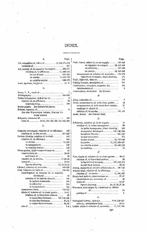
INDEX.
A. Page.
Air, admission of, effect of........... 6,139,171-172methods of.............................. 167
Air, supply of, to capacity developed...... 169-171relation of, to efficiency......... 11,108-172
to size of coal.................. 147-148to smoke................... 11,109-170to volatile matter.............. 169-170
Arch, ignition, height of..................... 17,77
B.
Beers, L. F., work of........................ 7Bibliography.............................. 185-186Boiler horsepower, definition of............. 8
relation of, to efficiency.................. 99chart showing....................... 100
Boiler plants. See Industrial plants.Boilers, capacity of.......................... 8
See also Water-tube boilers; Return tu bular boilers.
Briquets, character of..................... 1. 156tests Of.......... 10-11,154-155,150,101-162,184
C.
Capacity developed, relation of, to efficiency. 168 relation of, to size of coal.............. 147-148
Carbon dioxide, relation of, to draft.......... 143relation of, to efficiency ................. 143
to smoke........................... 11,143to temperature...................... 143to volatile matter.................... 143
Chain grates, draft measurements on ........ 18observations on......................... 15-32
summary of......................... 33relation of, to smoke.................. 17-18,33types of................................. 12-15
figures showing................ 13,14,15,16Clinker, relation of, to smoke.............. 149-153Coal, briquets of, tests of.................. 154-156
consumption of, relation of, to capacitydeveloped................... 10
relation of, to Carbon dioxide........ 144to carbon monoxide............. 144to efficiency..................... 144to temperature.................. 144
horsepower from...................... 173-175kinds of, relation of, to chain grates...... 16-17
relation of, to front-feed stokers...... 38to hand-fired furnaces..... 107,118,124to side-feed furnaces............. 55,64to under-feed furnaces........... 84,92
size of.................................. 7-8
Coal, size of, effect of, on air supply ....... 147-148on capacity developed...... 10,147-148on efficiency................... 147-148on smoke................... 10,147-148
temperature of, relation of, to smoke... 172-173relation of, to smoke, chart showing.. 174
Coals, high-ash, tests on..................... 146Coking furnace, description of............... 101Combustion, complete, necessity for......... 184
requirements of......................... 6Combustion, smokeless. See Smoke.
D.
Data, collection of........................... 7.Draft, measurement of, with chain grates.... 18
measurement of, with front-feed stokers.. 3G readings of, object of..................... . 7relation of, to smoke................... 156,163
Draft, forced. See Forced draft.
E.
Efficiency, relation of, to air supply......... 11relation of, to boiler horsepower......... 99
to boiler horsepower, chart showing. 100 to capacity developed......... 141,142,168to carbon dioxide.................. 141,142 'to coal consumed.................... 175to size of coal................... 10,147-148to smoke................... 11,142,165-167to volatile matter.............. 10,140,142to washing.......................... 11
Fire, depth of, relation of, to chain grates.... 16-17relation of, to front-teed stokers.......... 38
to hand-fired furnaces......... 107,118,124to side-feed stokers.................. 55,64
Firing, methods of, relative efficiencies of.. 145-146 Forced draft, relation of, to efficiency........ 11
relation of, to smoke............... 11,156,163Front-feed stokers, observations on.......... 37-47
observations on, summary of............ 48types of................................. 34-37
figures showing............ 34,35,36,37,38Furnaces, coal supply to, variations in, effects
of........................... 10placing of............................... 6
G. Geological Survey, tests by........... 9-10,139-167
tests by, conclusions from............... 10-11Grates, style of, relation of, to smoke.... 11,157,164
187
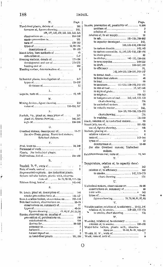
188 INDEX.
H.Haud-fired plants, defects of................ 101
furnaces at, figures showing.............. 105,106,107; 119,120,121,122,123,124
observations on........................ 103-138smoke prevention in..................... 101tests of................................ 139-143types of............................. 12,99-103
descriptions of...................... 99-139Hand firing, best methods of ................ 10
difficulties of............................. 6-7Heating stations, details of................. 177-184
development and use of................ 175-176heating cost of........................... 183
Heating surface, determination of............ 9
I. Industrial plants, investigation of........... 5-9
types of................................ 11-139divisions of.......................... 12
L. Lignite,tests of............................. 10,149
M. Mixing devices, figure showing.............. 103
value of........................... 102-103,167
N. Norfolk, Va., plant at, description of........ 131
plant at, figures showing.............. 140,141tests at................................ 139-144
0. Overfeed stokers, descriptions of............. 12-77
See also Chain grates; Front-feed stokers; Side-feed stokers.
P. Peat, tests on............................... 10,149Personnel of work........................... 7Plants. See Industrial plants.Publications, list of........................ 1S5-18G
R.
Randall, D. T., work of..................... 7Rate of work, unit of........................ 8Representative plants. See Industrial plants. Return tubular boilers, plants with, observa
tions of........ 64-76,92-98,117-138Ribbon firing, test of...................... 145-146
S.
St. Louis, plant at, description of............ 144smoke prevention tests at.............. 145-167
Scotch marine boilers, observation on...... 103-116Side-feed stokers, observations on........... 55-76
observations on, summary of............ 77types of................................. 48-54
figures showing.......... 49,50,51,52,53,54Smoke, observations on, making of.......... 7
prevention of, publications on............ 186conclusions on....................... 184devices for.......................... 99-100economy in.......................... 7factors in............................ 5f ormer report on..................... 5in hand-fired plants................ 101,184
Smoke, prevention of, possibility of......... 6,184problem of.......................... 5solution of........................... 5
relation of, to air supply.................. 11to ash........'............. 151-153,158-162to capacity developed............... 142,
143,151-155,158-162 to carbon dioxide................. 142,143to carbon monoxide. 11,143,151-155,158-166 to chain grates ...................... 33to clinker.................. 149-155,158-166to consumption.................... 149-153to draft........................ 156-157,163to efficiency......................... 10,
142,149-155,158-166,165-167 to forced draft....................... 11to front-feed stokers................. 48to load.............................. 99to moisture........ 151-153,158-162,165-166to size of coal................... 10,147-148to style of grate...................... 11to sulphur......................... 158-162to temperature of coal..... 142,143,172-173
chart showing................... 174to underfeed stokers................. 99to volatile matter.................... 142,
149-155,158-166,172-173 chart showing.................... 174
to washing........................ 156-160Stack, relation of, to underfeed stokers....... 99Steam jets,- use of.......................... 101-102
use of, figures showing................... 105Stokers, placing of............................ 6
relative values of........................ 6tests of................................ 143-144types of................................. 12
descriptions of....................... 12-99See also Overfeed stokers; Underfeed
stokers. Subbituminous coal, tests of:............... 10,149
T.
Temperature, relation of, to capacity, devel oped ........................ 142
relation of, to efficiency.................. 142to smoke...................... 142,172-173
chart showing................... 174
U. Underfeed stokers, observations on.......... 84-98
observations on, summary of............ 99.tests with ..................I...........? 143types of................................. 77-84
figures showing.......... 78,79,80,81,82,83V.
Volatile matter, relation of, to efficiency.. 10-11,140 relation of, to smoke........... 149-153,172-173
"* to smoke, chart showing............. 174W.
Washing, relation of, to efficiency..........; 11relation of, to smoke................... 156-160
Water-tube boilers, plants with, observa tions on....... 55-63,84-91,103-117
Weeks, H. W., work of...................... 7Work, rate of, unit of........................ 8
o