Embed Size (px)
Citation preview
THE SPACE SHUTTLEADVANCED SOLIDROCKET MOTOR
QUALITY CONTROL AND TESTING
(NASA-CR-188800) THE SPACE SHUTTLE ADVANCEDSOLID ROCKET MQTUR: QUALITY CONTROL ANDTESTING (NAS-NRC) 65 n CSCL 21H
N92-10043
Uncl asG3/20 0039570
NATIONAL RESEARCH COUNCIL
https://ntrs.nasa.gov/search.jsp?R=19920000825 2020-03-19T22:22:07+00:00Z
The Space ShuttleAdvanced Solid Rocket Motor
Quality Control and Testing
Committee on Advanced Solid Rocket MotorQuality Control and Test Program
Aeronautics and Space Engineering BoardCommission on Engineering and Technical Systems
National Research Council
National Academy PressWashington, D.C. 1991

NOTICE: The project that is the subject of this report was approved by the Governing Board of theNational Research Council, whose members are drawn from the councils of the National Academy ofSciences, the National Academy of Engineering, and the Institute of Medicine. The members of thepanel responsible for the report were chosen for their special competences and with regard for appropri-ate balance.
This report has been reviewed by a group other than the authors according to procedures approved by aReport Review Committee consisting of members of the National Academy of Sciences, the NationalAcademy of Engineering, and the Institute of Medicine.
The National Academy of Sciences is a private, nonprofit, self-perpetuating society of distinguishedscholars engaged in scientific and engineering research, dedicated to the furtherance of science andtechnology and to their use for the general welfare. Upon the authority of the charter granted to it by theCongress in 1863, the Academy has a mandate that requires it to advise the federal government onscientific and technical matters. Dr. Frank Press is president of the National Academy of Sciences.
The National Academy of Engineering was established in 1964, under the charter of the NationalAcademy of Sciences, as a parallel organization of outstanding engineers. It is autonomous in itsadministration and in the selection of its members, sharing with the National Academy of Sciences theresponsibility for advising the federal government. The National Academy of Engineering also sponsorsengineering programs aimed at meeting national needs, encourages education and research, and recog-nizes the superior achievements of engineers. Dr. Robert M. White is president of the National Academyof Engineering.
The Institute of Medicine was established in 1970 by the National Academy of Sciences to secure theservices of eminent members of appropriate professions in the examination of policy matters pertainingto the health of the public. The Institute acts under the responsibility given to the National Academy ofSciences by its congressional charter to be an adviser to the federal government and, upon its owninitiative, to identify issues of medical care, research, and education. Dr. Stuart Bondurant is actingpresident of the Institute of Medicine.
The National Research Council was organized by the National Academy of Sciences in 1916 toassociate the broad community of science and technology with the Academy's purposes of furtheringknowledge and advising the federal government. Functioning in accordance with general policies deter-mined by the Academy, the Council has become the principal operating agency of both the NationalAcademy of Sciences and the National Academy of Engineering in providing services to the government,the public, and the scientific and engineering communities. The Council is administered jointly by bothAcademies and the Institute of Medicine. Dr. Frank Press and Dr. Robert M. White are chairman andvice-chairman, respectively, of the National Research Council.
This study was supported by Contract NASW-4003 between the National Academy of Sciences and theNational Aeronautics and Space Administration.
Available in limited supply fromThe Aeronautics and Space Engineering BoardNational Research Council2101 Constitution Avenue, N.W.Washington, D.C. 20418
Printed in the United States of America
COMMITTEE ON ADVANCED SOLID ROCKET MOTORQUALITY CONTROL AND TEST PROGRAM
Laurence J. Adams, Consultant and Former President, Martin Marietta Corporation,Potomac, Md., Chairman
Janice L. Beadell, Manager, Advanced Supportability Technology, DouglasAircraft Company, Long Beach, Calif.
Jack L. Blumenthal, Assistant Director, Center for Automotive Technology, TRW,Redondo Beach, Calif.
Yvonne C. Brill, International Maritime Satellite Organization (Ret.), Skillman,N.J.
Charles P. Fletcher, Vice President, Engineering, Alcoa, Pittsburgh, Pa.Paul M. Johnstone, Eastern Airlines (Ret.), Saint Michaels, Md.Harold W. Lewis, Professor Emeritus, University of California, Santa Barbara,
Calif.James W. Mar, Professor Emeritus, Massachusetts Institute of Technology, Pacific
Grove, Calif,William A. Owcxarski, Director of External Technology Development, United
Technologies, Washington, D.C.
Advisors to the Committee
Donald L. Anton, Senior Research Scientist, Materials Technology, UnitedTechnologies Research Center, East Hartford, Conn. (June 24-September 1,1991)
William S. McArthur, NASA Astronaut Corps, Houston, Tex.
Staff
JoAnn C. Clayton, Study DirectorAllison C. Sandlin, Senior Staff Officer and Principal Study OfficerMartin J. Kaszubowski, Senior Staff OfficerChristina A. Weinland, Senior Project AssistantA.J. Medica, Consultant
in
PRECEDING PAGE BLANK NOT FILMED

AERONAUTICS AND SPACE ENGINEERING BOARD
Duane T. McRuer, President and Technical Director, Systems Technology, Inc.,Hawthorne, Calif., Chairman
James M. Beggs, Partner, J.M. Beggs Associates, Arlington, Va.Richard G. Bradley, Director, Flight Sciences, Ft. Worth Division, General
Dynamics, Ft. Worth, Tex.Robert H. Cannon, Jr., Charles Lee Powell Professor and Chairman, Dept. of
Aeronautics and Astronautics, Stanford University, Stanford, Calif.Eugene E. Covert, Professor, Dept. of Aeronautics and Astronautics, Massachusetts
Institute of Technology, Cambridge, Mass.Ruth M. Davis, President, Pymatuning Group, Inc., Arlington, Va.Wolfgang H. Demisch, Director of Research, UBS Securities, New York, N.Y.Charles W. Ellis, Retired Vice President V-22 Program, Boeing Vertol Company,'
Newtown Square, Penn.Owen K. Garriott, Vice President, Space Programs, Teledyne Brown Engineering,
Huntsville, Ala.John M. Hedgepeth, Retired President, Astro Aerospace Corporation, Santa
Barbara, Calif.Robert G. Loewy, Institute Professor, Dept. of Mechanical and Aerospace
Sciences, Rensselaer Polytechnic Institute, Troy, N.Y.John M. Logsdon, Director, Space Policy Institute, George Washington University,
. Washington, D.C.John H. McElroy, Dean of Engineering, University of Texas at Arlington,
Arlington, Tex.Garner W. Miller, Retired Senior Vice President for Technology, USAir, Naples,
Fla.Franklin K. Moore, Joseph C. Ford Professor of Mechanical Engineering, Cornell
University, Ithaca, N.Y.Harvey O. Nay, Retired Vice President of Engineering, Piper Aircraft Corporation,
Vero Beach, Fla.Frank E. Pickering, Vice President and General Manager, Aircraft Engines
Engineering Division, General Electric Company, Lynn, Mass.Anatol Roshko, von Karman Professor of Aeronautics, California Institute of
Technology, Pasadena, Calif.Maurice E. Shank, Retired Vice President, Pratt & Whitney of China, Inc.,
Bellevue, Wash.Thomas P. Stafford, Vice Chairman, Stafford, Burke, and Hecker, Inc., Alexandria,
Va.Martin N. Titland, Chief Operating Officer, CTA, Inc., Rockville, Md.Albertus D. Welliver, Corporate Vice President, Engineering and Technology, The
Boeing Company, Seattle, Wash.
IV

Staff
JoAnn C. Clayton, DirectorMartin J. Kaszubowski, Senior Staff OfficerAllison C. Sandlin, Senior Staff OfficerSusan K. Coppinger, Senior SecretaryAnna L. Farrar, Administrative CoordinatorMaryann Shanesy, Senior SecretaryChristina A. Weinland, Administrative Secretary
Contents
EXECUTIVE SUMMARY 1Introduction, 1Test Program, 2 ->Quality Assurance Program, 3Principal Findings and Recommendations, 4
TERMS, ACRONYMS, AND ABBREVIATIONS 7
1. INTRODUCTION 10Overview, 10'The Task, 12Approach, 13
2. CASE 14Description, 14
Materials Properties, 14Welding Properties and Processes, 15Structural Design, 16
Development Testing, 17Verification of the Structural Design, 17
Quality Assurance, 18Overall Case Findings and Recommendations, 18
3. INSULATION 20Description, 20Development Testing, 20
vn
PRECEDING PAGE BLANK NOT FILMED
viii CONTENTS
Development Testing Findings and Recommendations, 21Quality Assurance, 22Quality Assurance Findings and Recommendations, 22
4. LINER 23Description, 23Development Testing, 23Development Testing Findings and Recommendations, 24Quality Assurance, 24Quality Assurance Findings and Recommendations, 25
5. PROPELLANT 26Description, 26Development Testing, 27Quality Assurance, 29Overall Propellant Findings and Recommendations, 29
6. IGNITER 32Description, 32Development Testing and Quality Assurance, 32
7. NOZZLE 34Description, 34Development Testing, 35Quality Assurance, 36Overall Nozzle Findings and Recommendations, 36
8. OVERALL EVALUATION 38The ASRM Test Program, 38Quality Assurance Program, 39Schedule and Cost Risk, 39Availability of Skilled Personnel, 39Relationship Between Testing and Quality Assurance and Reliability
and Safety, 40Use of Probabilistic Risk Assessment, 40Automated Manufacturing Processes, 41
BIOGRAPHICAL SKETCHES OF COMMITTEE MEMBERS 43
APPENDIXESA Overall ASRM Test Program 47B Nondestructive Evaluation Methods 51C Component NDE Methods 52D Schematic of ASRM Test Program 54
Executive Summary
INTRODUCTION
The Congressional committees that authorize the activities of the National Aero-nautics and Space Administration (NASA) requested that the National ResearchCouncil (NRC) review the testing and quality assurance programs for the AdvancedSolid Rocket Motor (ASRM) program. This program is in its early developmentstages, with preliminary design review scheduled for February of 1992. Thus, theNRC review committee could only address design concepts, not final design; theplans for testing and quality assurance relating to these design concepts; and theresults of testing accomplished to date. Changes are likely to occur as more under-standing is developed from the analysis and test programs.
The proposed ASRM design incorporates numerous features that are significantdepartures from the Redesigned Solid Rocket Motor (RSRM) and, in some cases,from previous experience on other programs. The NRC review concentrated princi-pally on these features. Primary among these are the steel case material, weldingrather than pinning of case factory joints, a bolted field joint designed to close uponfiring the rocket, continuous mixing and casting of the solid propellant in place ofthe current batch processes, use of asbestos-free insulation, and a light-weight nozzle.Additionally, significant amounts of automation are to be incorporated in the manu-facturing processes.
This report contains the Committee's assessment of these and other features ofthe ASRM in terms of their potential impact on flight safety. The Committee'sprincipal focus was on the maturity of the technology used, the potential effective-ness of the analysis and test program in establishing the capability of the design to
1

2 THE SPACE SHUTTLE ADVANCED SOLID ROCKET MOTOR
provide safe flight, and the effectiveness of the quality assurance program in ensur-ing that the flight units are manufactured in compliance with the design require-ments.
The Committee generally accepted the ASRM design as a given and concentratedon evaluating the testing and quality assurance programs. However, design detailsand technology maturity strongly influence the testing and quality assurance pro-grams.
TEST PROGRAM
The Committee's review of the test program included the complete range of testsfrom basic materials characterization through full-scale motor firing tests (a detaileddescription appears in Appendixes A and D). The use of new materials for the case,its insulation, and the nozzle, as well as the case welding process requires thesuccessful completion of a large materials characterization experimental programprior to finalization of the design. The plans presented to the Committee indicatethat these issues are being addressed. However, the Committee notes that thisaspect of the ASRM program requires the amassing of a very large data base thatpresently does not exist.
Characterization of the case material is important since the selected material hasnot been widely used and there is limited experience in welding it. In addition tothe material's mechanical properties, the contractor must address items such as weldseam properties, characterization of the heat affected zone adjacent to the welds,residual stresses after welding, and potential stress corrosion cracking.
The test program for the case, as described to the Committee, is intended touncover unanticipated problems that result from using this material in the weldedcondition. The scope of the test program appears to the Committee to be adequate,but, because of the lack of previous experience with the particular alloy, may lead tosurprises that may require its augmentation.
Another major innovation in the ASRM design is the use of continuous mixingand direct casting of the propellant to replace the batch mixing and casting processemployed on most previous systems, including the RSRM and Titan III and IV. Thecontinuous mix process offers the potential for greater control of the mixing pro-cess, as well as for processing greater amounts of propellant with less waste. Theprogram for developing the continuous mix processes is being carried out by Aerojetat a pilot plant in Sacramento, California. The principal challenge is to provide,with a high confidence level, a homogeneous mix containing the correct amounts ofthe propellant mix constituents. While the selected propellant formulation is differ-ent than that used in the RSRM, it belongs to a family of propellants that has beenused for similar applications in the past. However, this particular formulation isunique to the ASRM. The test program must develop an experience base sufficientto provide the level of confidence required for human flight.
A visit to the pilot plant by a subcommittee of the Committee revealed that thepilot plant is well-designed and that the testing plan for process development iswell-conceived. Once the process has been developed and proven in the pilot plant,
SUMMARY 3
it must be scaled up by a factor of ten to a full-scale facility that is being built inYellow Creek, Mississippi. The Committee considers this to be a critical step withsignificant risk of delay in achieving the results promised by the pilot plant. Thisconcern is based on other experiences in working out the initial problems encoun-tered in automated manufacturing process equipment in a first-time, full-scale appli-cation.
The component, subsystem, and system test program has been based, in largepart, on experience from other large solid rocket motor development programs,especially the RSRM. The program includes firing of large numbers of small mo-tors, a series of ten 48-inch motors, and seven full-scale motors. These tests aredesigned to fully characterize propellant performance, evaluate new insulation andnozzle materials, evaluate the full-scale motor components, detect deficiencies inthe design, and ultimately to qualify the flight motors. Other major tests willqualify the case for reuse and demonstrate the structural integrity of the new motor.The many new design features incorporated in the ASRM require a comprehensivetest program to provide assurance for safe flight. The program described to theCommittee appears to incorporate the proper elements to do this but may need to beadjusted as more knowledge is gained. Strict test disciplines are mandatory. Theseinclude (prior to each test) establishment of pass/fail criteria, prediction of the per-formance and test results of each test article, and development of retest requirementsin the event of a test failure or anomalous results. At the time of this study, forexample, a decision had not been made whether or not the field joint structural testarticle (FJSTA) test of August 6, 1991, which was not successful, will be repeated.Such criteria should exist in advance of testing. In general, the Committee believesthat the objectives of a major test program should not be abandoned because of lossof the test article unless the objective of the test can be achieved as well or asexpeditiously by other means.
QUALITY ASSURANCE PROGRAM
The Committee's review of the ASRM Quality Assurance Program included thecomplete range from basic material formulation through final inspection of com-pleted segments.
A program that characterizes the critical constituents and properties of raw mate-rials, called "fingerprinting," is planned for all critical raw materials used in themotor. Each batch or shipment of material received will be subjected to fingerprint-ing inspections to assure that the supplier has not made changes that could affectfinal product quality. This program was initiated for the RSRM and is being ex-panded on for the ASRM. At the time of this report, a lack of details concerning theparameters to be monitored prevented the Committee from evaluating the finger-printing program planned for ASRM, but the Committee endorses the program inconcept.
The ASRM program team is implementing extensive nondestructive evaluation(NDE) procedures for monitoring the effectiveness of the process control programand for verifying the integrity of critical components (see Appendixes B and C).

4 THE SPACE SHUTTLE ADVANCED SOLID ROCKET MOTOR
These evaluations will be used to verify the quality of adhesive bonding in the case,liner, and nozzle; case metal; case welds; cast and cured propellant; and other criti-cal components. It was indicated to the Committee that the newest technology inNDE would be applied, including real-time radiography, ultrasonics, and electro-magnetic acoustic transducers. The new insulation, propellant, propellant-to-insula-tion liner, and nozzle materials require these NDE processes. Although the Com-mittee endorses such an NDE program, it cannot provide a detailed evaluation untilfurther developments have taken place.
An important feature of the quality assurance program is the segment hydroprooftest. This test is being designed to apply internal pressure to the motor case seg-ments in excess of the maximum expected flight pressures and sufficiently high todetect the presence of defects that could result in failure in flight. Such proof tests,combined with an effective NDE program, have provided high assurance of flightintegrity on previous programs. Final evaluation of the ASRM proof test programmust await completion of other analyses and tests.
The ASRM program team also expressed its intent to establish an extensive sta-tistical process control program. Such a program has the potential to provide datathat signal process deviations and that can lead to the identification of the root causeof repeated defects in manufactured components. Complete details of the ASRMprogram are not yet available and were not reviewed, but the Committee believesthat well-designed statistical process control could provide increased confidence inthe control of critical manufacturing processes.
In total, the Committee believes that the quality assurance program, as presentedduring this study, has the potential to minimize the probability of a defective flightarticle, to the extent attainable with the current technology.
PRINCIPAL FINDINGS AND RECOMMENDATIONS
The Committee has prepared numerous findings and recommendations on ASRMcomponents and processes. These appear throughout the body of the report. Thefollowing list, however, summarizes those findings and recommendations that havean overall application, or that were deemed by the Committee to be of such impor-tance that they warranted greater visibility.
• The numerous new developments of design features and manufacturing pro-cesses raise concerns as to the degree to which schedule and cost reserves havebeen incorporated in ASRM program plans. These reserves must, withoutcompromising the test and quality objectives, permit effective resolution of theunanticipated problems that will surely arise. The Committee did not conducta detailed review of schedule and cost reserves, so its concern is based on whatseems to be a success-oriented plan. It is recommended that program schedulesand budgets be reviewed to ensure that reasonable reserves have beenallocated for unanticipated problems.
• Experience has shown that even in the most well-designed programs, unantici-pated events occur during the testing and the first few flights due to undetected
SUMMARY
marginal designs and/or manufacturing process deviations. Tests yield thebest results when the objectives are well understood and criteria are defined inadvance. The Committee recommends that strict discipline be adhered toin defining test objectives, in establishing pass/fail test criteria, and inestablishing and meeting retest requirements.
A major objective stated for the ASRM is improved reliability and safety.While the Committee believes that, overall, the new design features and auto-mated manufacturing processes of the ASRM hold the potential for a morereliable, safer system than the current RSRM, the degree to which the ASRMis safer and more reliable than the RSRM is difficult to estimate in the absenceof a quantification (including uncertainty) of the safety and reliability of thetwo designs. The Committee believes that there is much to be learnedfrom such an exercise and recommends that quantification criteria forreliability and safety be identified and that a means for measuring progressin meeting the criteria be developed.
The Committee was divided on the issue of a general application of probabilis-tic risk assessment (PRA) to the ASRM design. However, it was in agreementthat selective applications could prove beneficial in assessing the risks of vari-ous design features as indicated in the body of the report. The Committeerecommends that NASA^evaluate the potential benefit to be derived froma general application of PRA at this point in time and of its application inthe specific instances that are discussed in the body of the report.
The new metal case utilizes a steel alloy that has not been extensively used ineither aerospace or commercial applications. Such large solid rocket motorcases previously have not been welded and flown, and the new case designemploys a welding process, to join the forged cylinder elements, that has notbeen proven. Several technical recommendations appear in the body ofthis report that, if adopted, would, in the Committee's evaluation, increasethe confidence level in the structural integrity of the case. We call par-ticular attention to those recommendations that concern stress corrosionsince, if present, stress corrosion has the potential to create defects aftercompletion of postmanufacturing tests and inspections, but prior to flight.
Solid rocket motors, of necessity, employ extensive adhesive bonding of ele-ments. The ASRM is no exception. Recent developments in process controltechniques and in nondestructive evaluation technology have tended to im-prove bond quality through the ability to detect defective bonds in the com-pleted assembly. The Committee examined current bonding processes andNDE plans for the ASRM program. It appears that current technology is beingused for adhesive bonding processes and inspections. The Committee recom-mends that the ASRM program team continue the strong emphasis onachieving and verifying adhesive bonding integrity and continue the workaimed at development of NDE processes for the nozzle bonds.
The continuous mix and cast process being developed for the solid propellant

6 THE SPACE SHUTTLE ADVANCED SOLID ROCKET MOTOR
is critical to the potential reliability and flight safety of the ASRM. Thesystem for monitoring the properties and constituents of the propellant mix isespecially important to developing a high level of confidence in the flightperformance of the motors. Some activity is planned to determine the effect ofprocess variations on motor performance and safety. The more tolerant thepropellant mix is to process variations, the higher the confidence level inachieving reliable flight. The Committee recommends that the plannedpropellant development and test program, which will investigate the effectof process variations, be expanded to include demonstration, in the five-inch motor tests, of the performance of propellant that is deliberatelymanufactured at the limits of the propellant specifications. In addition,the Committee also recommends that several of the 48-inch test motors bedirect cast from propellant from the continuous mix pilot plant and com-pared with earlier 48-inch motors cast from the batch mixed process.
• The ASRM incorporates a new, lighter-weight nozzle. Most of the weightreduction sterns from a newly designed flexible bearing and seal that is used toenable nozzle gimballing during flight. The weight of this bearing and sealassembly is reduced by approximately 50 percent from that of the RSRMnozzle. Therefore, the Committee recommends, in view of the dramaticweight reduction that has been promised, a more thorough review be madeof the nozzle design as soon as details permit quantitative assessments ofits safety and reliability.
Additional detailed recommendations that are specific to the major componentsof the ASRM design appear in the following chapters of the report.
The conclusions of this report are necessarily tentative because of the early stageof development of the ASRM. Issues raised here might fruitfully be revisited after12-18 months when a more accurate assessment of progress toward planned goalsshould be possible.

Terms, Acronyms, and Abbreviations
AEAlAPASRMATABurst Test
CCPCEICFDCILCOQCPDMEMATETExtrusion
FAFactor of Safety
Acoustic EvaluationAluminumAmmonium PerchlorateAdvanced Solid Rocket MotorAssembly Test ArticleTest in which pressurization exceeds the acceptable limit,resulting in bursting of the test articleCarbon Cloth PhenolicContract End ItemsComputational Fluid DynamicsCritical Items ListCertification of QualificationCenter Perforation (Test Motor)Development MotorElectromagnetic Acoustic TransducerEddy Current TestManufacturing and application process in which insulationmaterial is forced to flow plastically through an orificeFluorescence AnalysisNumber specified by the NASA Contract End ItemsSpecification and by the Marshall Space Flight CenterHandbook 505, which is used to calculate a margin ofsafety

THE SPACE SHUTTLE ADVANCED SOLID ROCKET MOTOR
FHAFJSTAFlexbearing
FlexsealFMEAFracture Toughness
FTIRHTPB
ICDIspJPLKSCLCE/HBTALDCCPLTMargin of Safety
Max-QMEOPMNASAMTNASANDENRCOSEEPBAN
PRApsiPTQMRSRMRTRTRSRMSSCSSMESTATEM
Functional Hazard AnalysisField Joint Structural Test ArticleStructural element that allows engine gimballing andcarries thrust loads. It is composed of layers of materialthat shear to enable movementProtects the flexbearing from hot gasesFailure Modes and Effects AnalysisFactor used to indicate the intensification of applied stressat the tip of a crack of known size and shape (seeToughness)Fourier Transform Infrared SpectroscopyHydroxyl-terminated polybutadiene, a solid rocketpropellant binderInterface Control DocumentSpecific ImpulseJet Propulsion LaboratoryKennedy Space CenterLife Cycle Endurance/Hydroburst Test ArticleLow-Density Carbon Cloth PhenolicLeak TestDefined as the allowable stress divided by the actualstress and the safety factor. The number 1 is subtractedfrom this calculated totalMaximum aerodynamic pressureMaximum Expected Operating Pressure48-inch test articlesMagnetic Particle TestNational Aeronautics and Space AdministrationNondestructive EvaluationNational Research CouncilOptically Stimulated Electron EmissionPolybutadiene-acrylic acid-acrylonitrile, a solid rocketmotor propellant binderProbabilistic Risk AssessmentPounds per square inchPenetrant TestQualification MotorRedesigned Solid Rocket MotorRadiography TestReal-time RadiographySolid Rocket MotorStennis Space CenterSpace Shuttle Main EngineStructural Test ArticleTechnical Evaluation Motor
TERMS, ACRONYMS, AND ABBREVIATIONS !
Toughness Ability of a material to absorb energy and deformplastically before fracturing
TPTA Transient Pressure Test ArticleTurnkey Operation Complex operation that can be initiated with little or no
design, process, or hardware delaysTVC Thrust Vector ControlTwang Load A short-duration, side load imposed on the Space Shuttle
system upon ignition of the Space Shuttle main enginesUT Ultrasonic TestingVAB Vehicle Assembly BuildingYC Yellow CreekYield Strength The stress at which a specified amount of permanent
deformation (usually 0.2%) is produced
Introduction
OVERVIEW
The Advanced Solid Rocket Motor (ASRM) is being developed to replace thecurrent Redesigned Solid Rocket Motor (RSRM) on the Space Shuttle. It is in-tended to improve flight safety and reliability by reducing catastrophic failure modesrelative to the RSRM and the pre-Challenger Solid Rocket Motor (SRM). Anothergoal of the program is to enhance producibility by building automated, dedicatedfacilities with efficient production tools while enhancing performance through in-creased amounts of a more energetic propellant and reduced inert weight.
The ASRM is intended to increase Space Shuttle payload capability by at least12,000 pounds. When flying 12 missions a year, it should be able to carry theequivalent payload of 14 current missions. This additional capability is gainedprimarily through an increase in the diameter of the ASRM, which increases thepropellant by approximately 100,000 pounds and adds an additional 10 seconds ofburn time.
The ASRM consists of six major components, each of which is dealt with indetail in separate sections of this report (see Figure 1). However, because of timeconstraints, the Committee was not able to perform a detailed evaluation of theigniter. Briefly, the components are:
• Case: Three cylindrical steel welded segments bolted together to -form themain body of the motor, which will be approximately 126 feet in length.
• Insulation: Material that protects the case from the heat generated by theburning propellant.
10

11
.coo
oT3I*OoE
•o<uo
>•o<
UJa:DO
12 THE SPACE SHUTTLE ADVANCED SOLID ROCKET MOTOR
• Liner: Material that provides critical bonding between the propellant and theinsulation.
• Propellant: Material that provides thrust when burned.• Nozzle: Part that accelerates the exhaust gasses from the combustion chamber
to a high velocity and through which the propellant exhaust gases are releasedto guide the direction of the rocket's thrust.
• Igniter: Mechanism that, when triggered, starts the propellant burn process,which produces the rocket booster thrust.
The ASRM is an untested design that makes use of materials and processes thatare either new or that vary from previous applications. These new features andprocesses are a principal focus of this review and will be discussed in the followingpages. They are:
• a different, more readily weldable, case alloy;• welded, rather than bolted, factory joints;• bolted field joints which are designed to close, rather than open, during propel-
lant burning;• new O-ring materials;• new, asbestos-free, insulation applied by a new automatic strip winding pro-
cess;• new liner material and new application process;• a propellant whose exact formulation has not previously been used;• a continuous mix and cast process for the propellant;• a water-soluble core around which the propellant will be poured;• a different solid rocket igniter design; and• new nozzle design with new materials.
Lockheed Missiles & Space Company, Inc. was selected as the ASRM primecontractor in April of 1.989 by the National Aeronautics and Space Administration(NASA). Lockheed is teamed with the Aerojet ASRM Division, which is theprincipal subcontractor responsible for the design, development, and production ofthe new motor. Currently, Lockheed and Aerojet are working in offices in luka,Mississippi, located about eight miles from the eventual plant site at Yellow Creek.RUST International, in Birmingham, Alabama, is the contractor responsible forconstruction of the Yellow Creek facility. Thiokol Corporation will manufacturethe nozzle at the NASA Michoud Assembly Facility near New Orleans, Louisiana.Babcock & Wilcox is responsible for manufacturing the case at locations in Indi-ana and Ohio.
Development of the ASRM is expected to take approximately six years, with thefirst new motors planned for a Space Shuttle flight in 1996.
THE TASK
In response to the NASA Authorization Act for Fiscal Year 1991, the NASAAdministrator requested that the National Research Council (NRC) assess the qual-
INTRODUCTION 13
ity and test program planned for the ASRM. The NRC was asked to review andevaluate program plans for quality assurance and testing and to assess their ad-equacy for ensuring safety and reliability. The NASA/ASRM program and its con-tractors provided the Committee with documentation and briefings describing the ASRMprogram and plans, focusing on the areas of quality assurance (including safety, reli-ability, and maintainability) and testing (including sub-scale tests, full-scale develop-ment tests, full-scale qualification tests, and other means of verification).
APPROACH
The full NRC Committee on ASRM Quality Control and Test Program met onMay 23-25, June 24-25, July 16-17, and August 5-7, 1991. The first two meetingswere held at the National Research Council in Washington, D.C. The third meetingwas held at the Lockheed/Aerojet facilities in luka, and the final meeting at theNRC Beckman Center in Irvine, California.
On June 5, 14, and 21, subcommittees met at the Marshall Space Flight Center toexamine technical details concerning the propellant; the Aerojet pilot plant in Sacra-mento, California, where the continuous propellant mixing process is being devel-oped; and at the Babcock & Wilcox Research Center in Alliance, Ohio, whereresearch and development are taking place for the ASRM case materials and pro-cesses. On July 31, another subcommittee visited the Thiokol Corporation facilityin Wasatch, Utah, where the design and development of the ASRM nozzle and itsproduction tooling and other processes are taking place.
At its first full meeting, the Committee familiarized itself with the ASRM pro-gram plans, including design, systems integration and engineering, verification methods,and safety analyses. At the second meeting, the Committee explored the roles andresponsibilities of the various NASA and contractor participants in program plan-ning and execution, the proposed materials and processes, and the ASRM testingand risk assessment program philosophies. At its third meeting, the Committeeexamined the Yellow Creek facility layout, including the implementation plan, safetyissues, and checks and balances between NASA, Lockheed, and Aerojet. Alsoincluded were detailed reviews of the development test plans and quality assuranceplans. The final meeting consisted of clarification of outstanding issues, Committeediscussions, and report writing.
The Committee requested a large number of written responses on various issuesand wishes to thank NASA and its contractors for their cooperation in providingexisting information and in researching some of the issues that arose. Throughoutthe short period of the study, ASRM program personnel were consistently forthcom-ing and helpful to the Committee in its work.
The ASRM program is still in the early stages of design and development. Ap-proximately 25 percent of the design is firm, and the preliminary design review isscheduled for February of 1992. Many materials and processes (from the pilotfacilities, for example) are not yet well established. Therefore, the Committeebelieves that the issues raised in this report should be reconsidered by a similarpanel in 12-18 months to assess progress of the program in meeting safety, reliabil-ity, and quality standards.

Case
DESCRIPTION
The ASRM motor case consists of three segments that require 11 welded factoryjoints, two bolted field joints, an integral external tank attach ring, and integralexternal stiffeners to resist the buckling loads induced by splashdown.
In contrast, the RSRM motor case is composed of four segments that requirethree bolted field joints, seven pinned factory joints and bolted external stiffeners.
The ASRM case is 150 inches in diameter, four inches greater in diameter than theRSRM case. This larger diameter increases the amount of propellant by approximately100,000 pounds. The ASRM case is essentially the same weight as that of the RSRM,since the weight gain associated with increased diameter is offset, primarily, by theweight reduction due to the elimination of the factory pinned joints.
Materials Properties
Due to the incorporation of welded joints in the ASRM case design, a weldablealloy was required. The RSRM is made of a well-characterized, highly studiedalloy, D-6ac. A nickel-cobalt steel alloy (HP 9Ni-4Co-0.3C commonly referred toas HP 9-4-30) was selected for the ASRM case material because of its high strength,good fracture toughness, improved stress corrosion resistance, and weldability.
A significant drawback of HP 9-4-30 is that it has not been as extensively used,and its behavior under complex loads, temperature, and strain rate conditions is notwell understood. In addition, commercial utilization of HP 9-4-30 has not includedwelding, even though it is classified as a weldable alloy. As part of the ASRM case
14

CASE 15
development process, base metal and weld characteristics are being evaluated indetail.
The HP 9-4-30 metal ingots, weighing approximately 40,000 pounds each, willbe obtained from two suppliers, Republic Steel and Latrobe. The ingots requiredwill be the largest produced by either supplier to date. Currently, more than 16 HP9-4-30 ingots have been produced.
Ladish Company, which forges the RSRM ingots, will also roll forge and coldsize the ASRM ingots. Previous to the ASRM program, they had not forged aningot this large, nor had they forged the HP 9-4-30 alloy. As of the date of thisstudy, they have gained some limited experience using four 146-inch diameter de-velopment forgings of the ASRM alloy. The ASRM HP 9-4-30 alloy is harder towork than the RSRM D-6ac alloy and may push the equipment at the Ladish Com-pany to the extent of its capabilities. However, analysis and experience at theLadish Company to date suggest that the chosen alloy can be successfully forged forASRM applications.
Welding Properties and Processes
The welded ASRM design, which eliminates the seven pinned factory joints, isnew to the large solid rocket motor industry. Successful welding of the very largecylinders, maintaining their concentricity, and relieving stress in the weld areas aresignificant challenges in the ASRM program.
Historically, welding of very large solid rocket motor cases has been avoided dueto the concern over the ability to repeatedly produce high integrity weld joints andto detect critical defects through nondestructive evaluation. The ASRM programteam justifies welding the factory joints over pinning on the following basis:
• Advances in weld process technology (plasma arc process; real-time TV moni-toring; process automation—all of which will be used in the ASRM program).
• Advances in nondestructive evaluation technology (real-time radiography andultrasonic testing).
The welding process introduces residual stresses in the area of the weld. A stressrelief cycle of the case segment at a moderately high temperature (900°F) will beused to partially relieve these residual stresses. Since a higher stress relief tempera-ture would result in undesirable base metal properties, significant levels of residualstress are expected to remain in the finished case. To provide a margin for thisresidual stress, as well as minor undetected welding flaws and joint inefficiencies,the material at the weld joint will be 25 percent thicker than the remainder of thecase material.
The maximum residual stress arising from the welding process, after stress relief,is expected by the ASRM program personnel to be reduced to approximately 40percent of the yield strength, which is still quite significant. It is the Committee'sunderstanding that each individual weld will not be assessed after heat treatment todetermine the adequacy of the stress relief.
16 THE SPACE SHUTTLE ADVANCED SOLID ROCKET MOTOR
The automated plasma arc welding process is expected to produce higher-qualityweld joints than previous processes; however, repairs of defective welds will still berequired. Repair procedures are being developed concurrently with the weldingprocess. The ability to make high-quality repairs, and to verify their integrity withnondestructive evaluation techniques, is of crucial importance.
Currently, a thorough evaluation is being carried out at Babcock & Wilcox (B&W)on the welding parameters to be used in manufacturing the case segments. B&Whas had little prior experience with HP 9-4-30, and the industry data base is small.Thus, an extensive research program is necessary. Joint geometry and weldingparameter variations are being assessed. Also planned, but not completed, are ex-tensive strength and fracture toughness tests of the weld and heat affected zoneadjacent to the welds. Until these tests are completed, it will not be possible todefinitively qualify the welded joint geometry.
Structural Design
The ASRM program team stated the following as advantages over the currentRSRM design:
• Field joints that close during firing instead of opening, as for the RSRM.• Welded factory joints that eliminate potential failure modes associated with
the pinned factory joints used in the RSRM.• Face type seals that are designed to make it easier to assemble the field joints.• An HP 9-4-30 ASRM alloy that has a higher fracture toughness than the D-6ac
RSRM alloy and is more resistant to stress corrosion cracking.• O-ring seal material that retains its resiliency at low temperatures (thereby
enabling the elimination of O-ring joint heaters) and that will be compatiblewith the required grease application.
However, the Committee believes:
• The ASRM field joint is more complex in that the bolts are in tension rather thanin shear, the joint itself is more difficult to machine, and fit-up stresses are morelikely to occur. Additionally, the joint is more difficult to analyze.
• The weld and the heat affected zone surrounding the weld present potentialnew failure modes that are not currently completely understood.
• Proof testing is the process whereby structural safety is assured for the nextflight of the case and hence fracture toughness, per se, is not a measure ofgoodness. (For analytical purposes, it should be noted that both the ASRMand the RSRM use the same value of plane strain fracture toughness. How-ever, fracture toughness does not affect the design of the case.) A moreappropriate measure of goodness is the square of the ratio of fracture tough-ness to tensile yield stress, which is the critical crack size. Using this com-parison, the RSRM D-6ac alloy is somewhat better than the ASRM HP 9-4-30alloy, although both appear to be acceptable.
CASE 17
DEVELOPMENT TESTING
Verification of the Structural Design
The existing material data base for the case alloy is not extensive since there havebeen very few prior applications. Consequently, a comprehensive test program hasbeen planned to gather the data base required for the ASRM design. It should benoted that the necessary material data base is much larger than that needed for theRSRM because of the additional welding parameters that must be assessed.
The stresses in the bolted field joint were scheduled to be verified by strain gagemeasurements in the Field Joint Structural Test Article (FJSTA), which was a 146-inch diameter, geometric replica of the full-scale ASRM joint made from D-6acsteel. The D-6ac alloy was used because of its availability, which would allow thetest to be conducted sooner than using HP 9-4-30 forgings. On August 6, 1991, thescheduled FJSTA failed prematurely at approximately one-fourth of the maximumexpected operating pressure. It has been ascertained that the failure was in the case,not in the joint. NASA has appointed an investigation team, which, at the time ofthis report, has not published any findings. Important objectives of the test were toverify that the joint closes upon pressurization and to evaluate the complex stresspatterns previously noted. These and other test objectives were not achieved.
The FJSTA was the first scheduled major test that was unique to the ASRM. TheCommittee believes it is important that another test article be fabricated as soon aspossible in order that the originally planned series of tests can be completed or thatan alternate test program be developed that can acquire the necessary data on anequivalent time scale.
Other critical parameters of the ASRM case design are expected to be verified bya series of tests that appear to faithfully duplicate the tests that were used to verifythe SRM and RSRM designs. These tests bear the acronyms TPTA, LCE/HBTA,STA, DMs, and QMs, and include the Pathfinder test article (see Appendixes A andD). The ASRM requires additional testing beyond that required for the RSRM,because new materials are being used as well as because of the use of welded joints.
The structural integrity requirements imposed on the ASRM case are the same asthose imposed on the RSRM. According to the results of theoretical calculationsusing computer models, case membrane thickness and the geometry of the machinedpockets for the bolted field joint are sufficient to show positive margins of safetyagainst the yield and ultimate tensile strengths of the HP 9-4-30 alloy. The geom-etry and thickness in the area of the weld also show positive margins of safetyagainst the properties of weld and heat affected zone. The stiffeners on the aftsegment are sized to show positive margins of safety against the loads imposedduring splashdown. Positive margins are also shown for the stresses induced by theso-called "twang" loads. It should be noted that detailed stress analyses are still inprogress.
The structural adequacy of the ASRM will be further assured for each flight bysubjecting each segment to a hydroproof test together with nondestructive evalua-tion. Different test configurations will be used for the forward, center, and aft

18 THE SPACE SHUTTLE ADVANCED SOLID ROCKET MOTOR
segments to ensure faithful simulation of the end conditions. This represents animprovement over the RSRM. At the present time, the parameters of the hydroprooftest have not been determined pending fracture mechanics evaluation and otheranalyses and tests. For the RSRM, the hydroproof pressure is 12 percent higherthan maximum expected operating pressure (MEOP). The hydroproof test, which,in reality, is a form of inspection (albeit potentially destructive) uses a state of stressas the means to interrogate the structure for critically sized cracks. Final evaluationof the effectiveness of the ASRM hydroproof test can be made only after the testparameters are established.
It should be noted that the hydroproof test simulates only the pressure arisingfrom the firing of the motor and does not simulate the stress conditions associatedwith either the "twang" or splashdown loads.
QUALITY ASSURANCE
Inspection and quality assurance tests are performed throughout the case manu-facturing process. Initial ingot castings of approximately 40,000 pound melts arebeing produced by Latrobe and by Republic Steel. The testing at this stage concen-trates on the quality of the material using standard metallurgical practice, includingspectral analysis, to ensure chemistry conformance to within alloy specifications.
The ingots are shipped to the Ladish Company for roll forging and are roughmachined into case sections. Quality assurance tests ensure conformance to dimen-sional, mechanical property, and defect specifications, before the case sections aresent to Babcock & Wilcox.
At B&W, the forgings will be further cleaned, machined, and welded into thefinal configurations. They also will be given several heat treatments to produce thedesired microstructure and to relieve the residual stresses in the weld heat affectedzone. Throughout these processing steps there will be frequent nondestructive in-spections for flaws. A variety of techniques will be used, which include eddycurrent testing, dye penetrant tests, ultrasonic tests, and real-time radiography. Ofall these, only the ultrasonic and radiography techniques are capable of detectingsmall, wholly subsurface flaws.
The Committee's judgement is that the overall production testing program issound in concept.
OVERALL CASE FINDINGS AND RECOMMENDATIONS
• The FJSTA test failure leaves several important questions unanswered con-cerning the anticipated performance of the new field joint design; the circum-stances that led to the unexpected failure on August 6, 1991, in the RSRMsteel case; and whether the test will be rescheduled. At this writing, a decisionhas not been made regarding the construction of a replacement test article. Itis recommended that another FJSTA be fabricated with a sense of urgencybecause these data are needed to verify the joint integrity and structuralperformance, i.e., that the joint really closes, or that an alternate test
CASE 19
program be developed that can acquire the necessary data on an equiva-lent time scale.
• The margins of safety are calculated using the von Mises criterion for materialfailure, to account for the complex states of stress in the membrane and thejoint. The Committee recommends that some pressurized cylinder tests beconducted to validate the von Mises criterion for the HP 9-4-30 ASRMalloy.
• The loads imposed on the case during splashdown have caused extensive dam-age to the SRM and RSRM case. The Committee believes a new examina-tion of the loads induced by entry into the ocean, referred as the cavitycollapse loads, should be initiated.
• Data indicate the HP 9-4-30 ASRM alloy has a stress corrosion cracking thresholdsuperior to the D-6ac RSRM alloy. However, the ASRM case has weldedfactory joints and field joints that are in tension. These welded joints make theASRM design potentially more sensitive to stress corrosion cracking whencompared to the RSRM. Stress could also result from hydrogen embrittlementand time-delayed phase transformation. The Committee recommends de-tailed investigation of the stress corrosion cracking susceptibility of thewelds and of the weld heat affected zone.
• An extensive study should be initiated to evaluate the temperature andstrain rate effects and the forging production effects on fracture and crackgrowth. Also, more extensive stress corrosion analysis, as well as biaxialand complex loading studies, should be performed on the HP 9-4-30 ASRMalloy.
• An inspection process should be implemented to ensure that the postweldanneal has sufficiently lowered the residual stresses in each weld.
• A statistical analysis should be made of the weld defects that are detected.These data, when presented in the form of a probability of occurrence, will beof value to the quality assurance program. Some of these defects may requirean evaluation to determine their effect on fracture and strength. An effectiveframework for quantifying the safety and reliability implications of these de-fects would be a probabilistic risk assessment.
Insulation
DESCRIPTION
The purpose of the case insulation is to protect the steel case from the very high-temperature propellant flame. The RSRM insulation contains a large amount ofasbestos, which is both an environmental and manufacturing concern. Accordingly,the ASRM design team has elected to change to an asbestos-free insulation (a Kevlarfiber-reinforced rubber material). It is, of course, critical that the new insulationprovide the proper thermal protection and be adequately bonded to both the steelcase and the propellant liner material. The development and verification test pro-gram planned for the new insulation is aimed at verifying the adequacy of insulationand bonding properties of the new material system.
An automated stripwinding technique is planned for applying the insulation to theprimed steel cases. The RSRM design does not use an automated stripwinder butrather applies the insulation by a manual process. Thus, since the stripwindingprocess, as applied to the inside of the very-large-diameter ASRM cases has onlybeen used on the new Titan IV solid rocket motor, it will require further develop-ment.
DEVELOPMENT TESTING
Aerojet has completed a comprehensive laboratory investigation to develop anoptimum formulation for the ASRM insulation and the proposed stripwinding ap-plication technique. A baseline specification was developed for the selected for-
20
INSULATION 21
mulation, and four commercial vendors are producing products to meet the re-quirements.
A pilot plant is being built in Sacramento to develop the stripwinding process toapply the new ASRM insulation. The technology developed in the Sacramento pilotplant will be the basis for the design of the full-scale equipment located in YellowCreek. The pilot plant will be capable of demonstrating the stripwinding extrusionprocess on full-scale diameter cylinders but will have only a four-foot axial traverse,while the actual production plant operation will be required to travel the entirelength of the ASRM segment (approximately 40 feet).
The process development program will concentrate on establishing stripwinderextrusion parameters and controls and will evaluate materials supplied by the fourvendors from the same specification. Both nominal operating conditions and ac-ceptable parameter tolerances will be developed, extremes of equipment capabilitywill be established, and parameters and controls will be established for the cureprocess.
The ablative performance of the ASRM insulation material prepared in the Sacra-mento pilot plant will be initially evaluated in 48-inch diameter motors. Two of thefive 48-inch test motors will contain four manually-applied insulation liner "swatches"manufactured from specification material supplied by the four material vendors.These materials will be compared with RSRM insulation in the same test motor.The remaining three motors will be insulated by the pilot plant stripwinding process.Insulation for the seven full-duration, full-scale motor tests will be applied with thefull-scale manufacturing equipment at Yellow Creek.
DEVELOPMENT TESTING FINDINGS AND RECOMMENDATIONS
The Committee believes that the plan for developing and testing the insulationmanufacturing process and the resulting product is well thought out and thorough.There is a high probability that pilot plant material will be successfully applied tothe test articles. The likelihood of quick success in moving from pilot plant to full-scale production is, however, less certain. It is likely that significant developmentwill still be required with the full-scale equipment before the process is fully proven.
While it is expected that the ASRM insulation will perform as well as the RSRMinsulation, the ASRM program team will not have a significant indication of thisuntil the 48-inch motors are tested and cannot be really confident until after somefull-scale testing. The Committee recommends that:
• Contingency planning be done to account for the possibility that a greater thanexpected ablation rate may occur with the new insulation.
• The program team consider a backup approach to the automated stripwinderthat utilizes manual application of the insulation.
• The program team should plan for some additional development work in thefull-scale stripwinding facility, which may go beyond the currently plannedtooling dry runs, full-scale test articles, and the Pathfinder motor.
22 THE SPACE SHUTTLE ADVANCED SOLID ROCKET MOTOR
QUALITY ASSURANCE
Quality assurance for the automated stripwinding insulation process includesnondestructive evaluation of both the critical bondlines and insulation thickness, aswell as destructive testing of witness samples that are produced at the same time thatthe cases are insulated. The automated ultrasonic approach to nondestructive testingis reported to be more sensitive than the current RSRM method and to provide betterresolution of unbonded areas.
QUALITY ASSURANCE FINDINGS AND RECOMMENDATIONS
The planned approach to both nondestructive and destructive evaluation of thecase insulation is, in the opinion of the Committee, well conceived. The ultrasonictesting equipment to be used on the ASRM should lead to a thorough evaluation ofthe critical bondlines and, hence, a high confidence in the soundness of the insula-tion product.
The approach to controlling the incoming insulation materials planned for theASRM should also lead to a superior product. This includes second-tier specifica-tions of raw materials prepared by the ASRM project team and a program of de-tailed chemical characterization of the incoming materials, called fingerprinting.The Committee has no recommendations in this area.
Liner
DESCRIPTION
The ASRM liner provides the bond between the propellant and the insulation.This is a critical area, since loss of bonding between the propellant and the insula-tion can lead to catastrophic failure. The ASRM liner must bond successfully toboth the propellant, with its HTPB (hydroxyl-terminated polybutadiene) binder, andthe insulation. The liner consists predominantly of a carbon-reinforced HTPB poly-mer. A bonding agent, HX752, is used to increase mechanical strength. For SpaceShuttle applications, this is an entirely new liner material system. However, there isa substantial history of use with the HTPB-based ASRM propellant family on otherprograms. The liner material will be batch mixed and applied to the insulation by anautomated spray process to reduce contamination and enhance reproducibility.
DEVELOPMENT TESTING
The liner development and verification program is aimed at selecting detailedformulations, defining the sensitivity of material properties to variations in composi-tion and processing conditions, establishing material and process specification lim-its, and verifying that the material properties of the manufactured liner satisfy therequirements. One of the key requirements is that the factor of safety for thepropellant/liner bond be greater than or equal to 2.0 during the total shelf life of theASRM.
The current plan involves developing the liner manufacturing and control pro-cesses by laboratory and pilot plant experimentation at the same time that the allow-
23
24 THE SPACE SHUTTLE ADVANCED SOLID ROCKET MOTOR
able ranges of liner composition are determined. This ensures adequate processcontrol over the allowable range of liner composition. The laboratory and pilotplant work is being carried out at the Aerojet facility in Sacramento, and the processdata will be used to design the full-scale facility at Yellow Creek.
DEVELOPMENT TESTING FINDINGS AND RECOMMENDATIONS
The Committee believes that the plan for obtaining key data on baseline linerformulation, allowable ranges of compositional variance, and process controls iswell designed and thought out. It also believes that developing the proper linerchemistry and specification limits will not turn out to be a major issue. The scalingof the mechanical and automated control parts of the spray process from the rela-tively small pilot facility to a full-scale motor segment could, however, turn out tobe more of a problem. In addition, the process must be qualified to cover the rangeof cleanliness and water vapor that may be present in the full-scale motor processingduring scale up of the liner application process.
The Committee recommends that after the liner specification is complete,one or two longer pilot plant runs be made at the extremes of the allowableliner compositional ranges to ensure that bonds that meet design strength re-quirements can be made even when the composition is near the limits of thespecification. If feasible, it is desirable to use the automated spray facility pilotplant to prepare liner at the limits of the specification on the 48-inch motor insula-tion.
The Committee believes that the transfer of automated liner spraying technologyfrom pilot plant to full-scale production will not be a "turnkey" operation, that is,there will be considerable work needed to make the process work effectively oncethe process has been proven and the facilities are constructed. Accordingly, theCommittee suggests that the contingency planning for the activation of the manu-facturing facility include the time and resources to do additional developmentaltesting with the full-scale equipment.
QUALITY ASSURANCE
The Committee believes that the ASRM program team has centered its approachto liner quality assurance on extensive and careful control of the manufacturing unitoperations and incoming raw materials. The ASRM program team feels, and theCommittee also believes, that keeping the processes and raw materials under controlis the key to keeping the liner product within specifications. Accordingly, majoremphasis is aimed at monitoring and controlling the processes and starting materi-als.
The ASRM program team has selected an automated ultrasonic inspection systemfor nondestructive evaluation of the propellant-to-insulation bondline. This willprovide greater resolution for unbonded areas than is possible by x-ray analysis. AllNDE tests should be checked and calibrated with deliberately-introduced and mappedvoids in such a way as to characterize test effectiveness.

LINER 25
QUALITY ASSURANCE FINDINGS AND RECOMMENDATIONS
The Committee believes that the program planning in the area of liner qualityassurance and nondestructive testing is well thought out and should result in a goodproduct. It was pleased to see that many of the lessons learned from the originalSRM program regarding the need for very careful control of the physical and chemi-cal properties of the raw materials will be carried out. The Committee also believesthat automated ultrasonic inspection of the critical bondlines should lead to a morereliable product.
While the Committee believes that the quality assurance plans for manufacturingthe liner are good, successful implementation has yet to be proven. The Committeebelieves that the ASRM program team should be prepared for anomalies andsurprises in this area and, as in other critical areas of ASRM design and pro-duction, should be aware of the need for adequate schedule flexibility.
Propellant
DESCRIPTION
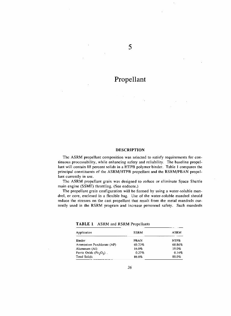
The ASRM propellant composition was selected to satisfy requirements for con-tinuous processability, while enhancing safety and reliability. The baseline propel-lant will contain 88 percent solids in a HTPB polymer binder. Table 1 compares theprincipal constituents of the ASRM/HTPB propellant and the RSRM/PBAN propel-lant currently in use.
The ASRM propellant grain was designed to reduce or eliminate Space Shuttlemain engine (SSME) throttling. (See endnote.)
The propellant grain configuration will be formed by using a water-soluble man-drel, or core, enclosed in a flexible bag. Use of the water-soluble mandrel shouldreduce the stresses on the cast propellant that result from the metal mandrels cur-rently used in the RSRM program and increase personnel safety. Such mandrels
TABLE 1 ASRM and RSRM Propellants
Application RSRM ASRM
Binder PBAN HTPBAmmonium Perchlorate (AP) 69.73% 68.86%Aluminum (Al) 16.0% 19.0%Ferric Oxide (Fe2O3) . 0.27% 0.14%Total Solids 86.0%
26
PKOPELLANT 27
have been used in this application primarily in small intercontinental ballistic mis-sile programs.
A significant experience base exists in the solid propellant industry with thefamily of HTPB propellants. On the order of 80 to 100 million pounds per year isproduced for the Multiple Launch Rocket Systems, Delta Launch Vehicle Castor IV,Peacekeeper, and Titan IV. However, the continuous mix and cast process beingused for the ASRM requires a unique formulation.
Based on the potential for improved safety and quality, the ASRM program teamselected an automated continuous mixing process which is a significant change fromthe batch mixing process currently used to produce the RSRM propellant. In addi-tion, there is limited experience with the continuous mix and direct cast process, andthe rate of propellant production will be almost ten times larger than has beenpreviously demonstrated.
DEVELOPMENT TESTING
An extensive series of tests has been planned and is being implemented to com-plete the development of the propellant formulation and the manufacturing process.
A pilot plant of the proposed propellant manufacturing facility has been built byAerojet in Sacramento and is currently in operation. The purpose of the pilot plantis to develop an understanding of all key process parameters required to develop amanufacturing process that is controllable and capable of producing a motor thatmeets all specifications. Laboratory and pilot plant data are being used to developthe material and process specifications.
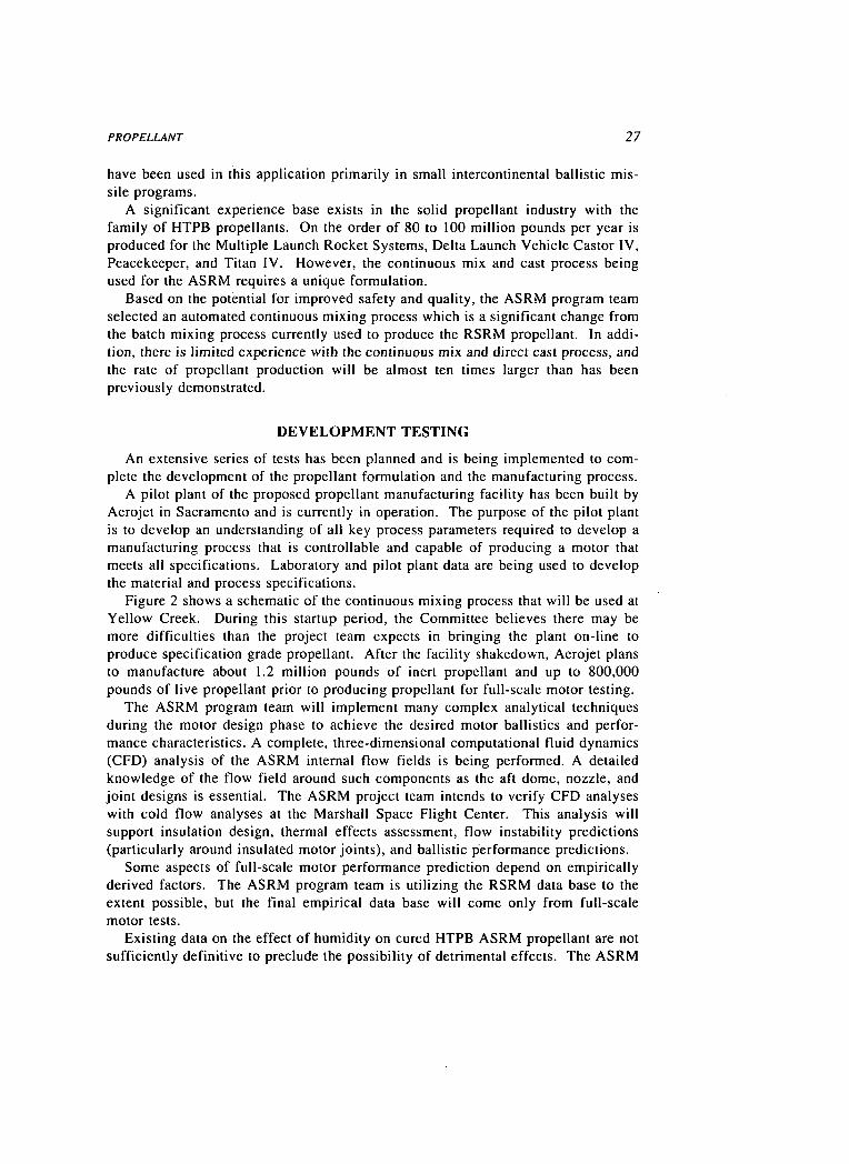
Figure 2 shows a schematic of the continuous mixing process that will be used atYellow Creek. During this startup period, the Committee believes there may bemore difficulties than the project team expects in bringing the plant on-line toproduce specification grade propellant. After the facility shakedown, Aerojet plansto manufacture about 1.2 million pounds of inert propellant and up to 800,000pounds of live propellant prior to producing propellant for full-scale motor testing.
The ASRM program team will implement many complex analytical techniquesduring the motor design phase to achieve the desired motor ballistics and perfor-mance characteristics. A complete, three-dimensional computational fluid dynamics(CFD) analysis of the ASRM internal flow fields is being performed. A detailedknowledge of the flow field around such components as the aft dome, nozzle, andjoint designs is essential. The ASRM project team intends to verify CFD analyseswith cold flow analyses at the Marshall Space Flight Center. This analysis willsupport insulation design, thermal effects assessment, flow instability predictions(particularly around insulated motor joints), and ballistic performance predictions.
Some aspects of full-scale motor performance prediction depend on empiricallyderived factors. The ASRM program team is utilizing the RSRM data base to theextent possible, but the final empirical data base will come only from full-scalemotor tests.
Existing data on the effect of humidity on cured HTPB ASRM propellant are notsufficiently definitive to preclude the possibility of detrimental effects. The ASRM

28
2CLX'g
cfl3O3C
COO
U
OE
PROPELLANT 29
program team is cognizant that humidity control requirements for ASRM propellantdiffer from RSRM propellant, and it is the Committee's understanding that this willbe accommodated by a combination of testing (to determine humidity effects on thepropellant characteristics) and provision for propellant protection during mixing,after casting, and when shipped to Kennedy Space Center (KSC). At KSC, exposureto humidity will be minimized by end caps on the segments and a nozzle plug. Afull-scale motor "aging test article" is planned to demonstrate the five-year servicelife requirement.
QUALITY ASSURANCE
During the continuous mix process, the system for monitoring the properties andconstituents of the propellant mix is critical in producing an acceptable propellantfor the flight motor. The propellant composition will be monitored and verifiedprior to casting by in-line densitometer analysis and by laboratory tests that will betaken every 20 minutes to assure compliance with mix standards. If the test resultsare unacceptable, the propellant will be diverted to scrap. There is a 30-minutedelay loop in the continuous mix line to accommodate the necessary laboratorytests. There are plans for additional in-line techniques, such as Fourier TransformInfrared Spectroscopy (FTIR) and x-ray fluorescence analysis (FA), that promisesuperior control and which would permit automation of the quality monitoring pro-cess. The Committee urges the ASRM program team to continue developing theseadditional in-line techniques.
During the continuous casting of the ASRM motor segments, typical small testmotors (e.g., five-inch CP and ballistic motors) will also be cast and cured for laterevaluation as is done at present in the RSRM program. After casting, x-ray andultrasonic techniques will be used to inspect each completed ASRM segment afterthe core has been removed.
Ten 48-inch test motors used primarily for insulation and nozzle tests will alsoprovide propellant burn rate data, but not propellant ballistic data. The number ofthese motors that will be continuously mixed and direct cast has not yet been deter-mined.
The seven planned full-scale development and qualification motor tests will pro-vide critical information on propellant performance characteristics. The test objec-tives of these DM and QM tests are described in Appendix A.
OVERALL PROPELLANT FINDINGS AND RECOMMENDATIONS
• From a conceptual standpoint, the Committee believes that after proper docu-mentation and instrumentation, the continuous mix process promises adequateprocess control. With proper characterization of the individual operations, itshould be possible to bring the mixing process under a state of statisticalcontrol that will allow the production of reliably mixed propellant with aconsistent composition.
• Significant development activity will be required to provide design parameters
30 THE SPACE SHUTTLE ADVANCED SOLID ROCKET MOTOR
for the full-scale process, the necessary process controls, and the allowable com-position ranges that must be controlled to ensure that the propellant productmeets operational requirements. The plant equipment at Yellow Creek will haveto be ten times larger than the equipment in the pilot plant, and there necessarilywill be significant learning, debugging, and, in some cases,' redefinition of char-acteristics. There is very little margin in the planning to accommodate anoma-lies. The Committee recommends schedule and budget flexibility for addi-tional pilot plant runs (which are not identified at this time) that will berequired to retest and understand anomalies when and if they occur.
• The ASRM program team believes that the continuous mix process will beable to control the compositional variances and product inhomogeneity betterthan current batch mix processes. The data to prove this, however, do not yetexist and must come from the pilot plant testing program. It is likely that thecontinuous'liquid feeders to the mixer will provide liquid stream variance thatis as low as batch mixing processes. There is some concern over the ammo-nium perchlorate powder feeders, which operate under different control modes(gravimetric operation over a large part of the cycle and volumetric operationover a second, smaller part). The Committee recommends a thorough evaluationof the burning rate and chemical composition of material produced duringvolumetric operation. It also recommends that several of the 48-inch testmotors be direct cast from propellant from the continuous mix pilot plantand compared with earlier 48-inch motors cast from the batch mixed pro-cess.
• Current planning for pilot plant runs of propellant at the extremes of the speci-fication limits is incomplete. Understanding the sensitivity to process vari-ables is very important. Increased tolerance to these variables decreases flightrisk. In view of this, the Committee recommends that the ASRM programteam make one or two longer pilot plant runs, after the propellant specifi-cation has been finalized, at the extremes of the propellant specifications,using the continuous mix process. This material then should be cast intofive-inch CP motors and tested. Burn rate results should be comparedwith nominal propellant mix.
• There are no test motor firings planned for motor sizes between the five-inchCP motors, with 10 pounds of propellant, and the full-scale ASRM tests thatwill specifically address the propellant qualities. The fact that propellant pro-cessing and ballistic suitability cannot be determined until the first full-scaledevelopment motor test presents the risk of delay in the event that predictedresults are not achieved. Current scheduling of subsequent development motorfirings allows minimum time for adjustments to the propellant mix if thatshould be required. The initiation of qualification motor casting before thedevelopment motor tests are complete compounds the problem. The Commit-tee recommends that the schedule be reexamined to ensure sufficient dis-tancing between full-scale development motor tests to enable moderatepropellant reformulation if required.

PROPELLANT 31
NOTE
1. During launch, as the Space Shuttle speed increases, the system is subjected to large aerodynamicforces (Max-Q). During this time, the thrust of the engines is reduced (throttled) to reduce stressesimposed on the system. Once the Shuttle system has passed Max-Q, the aerodynamic forces subsides andthe SSME thrust is increased. Even though no catastrophic failure has occurred, there are potentialfailure modes associated with SSME throttling. The ASRM grain is being designed to inherently reducethrust to limit Max-Q, which would eliminate or reduce SSME throttling.

Igniter
DESCRIPTION
The igniter contains solid propellant that, when burned, sends high-temperaturegases into the motor which, in turn, ignite the ASRM propellant.
The objective of the new ASRM igniter design was to improve the performanceand enhance safety through elimination of a large number of potential leak paths andto reduce pressure upon ignition through the use of multiple ports, new propellantand insulation, and a different grain design. The igniters will be manufactured atthe Aerojet facility in Sacramento, shipped to the Yellow Creek facility, and in-stalled into the assembled ASRM.
DEVELOPMENT TESTING AND QUALITY ASSURANCE
The comprehensive development and test program for the ASRM igniter includescomponent pressurization tests, pressure seal verification tests, component bursttests, and ballistic performance tests. In addition, a heavyweight igniter will befired in September 1991 to evaluate the start characteristics of the igniter grain. Aflight-weight ASRM igniter, installed in a technical evaluation motor (TEM) andloaded with RSRM propellant, will be test fired early in 1993. The TEM test willevaluate the multiport igniter and confirm the ignition transient model. Furtherigniter characteristic data will be obtained from the three DM tests and the four QMtests.
Material process controls for the new ASRM igniter design will be ensured byfingerprinting.
32
IGNITER 33
During the briefings, the Committee received the impression that NASA and thecontractor were applying the lessons that had been learned from RSRM igniterexperiences. However, the Committee did not perform an in-depth examination ofthe igniter and has no recommendations.
Nozzle
DESCRIPTION
The design of the ASRM nozzle is intended to improve the overall performanceof the motor, when compared to the RSRM design, while also enhancing both reli-ability and safety. The performance gains are accomplished primarily through areduction in the overall weight of the nozzle. A new, compact flexbearing/flexsealdesign reduces the weight of the nozzle, from that of the RSRM, by approximately4,250 pounds. The use of a new low-density carbon cloth phenolic (LDCCP) abla-tive material in the nozzle's aft exit cone and fixed housing saves approximately700 pounds. The total weight reduction from two ASRM nozzles per launch is onthe order of 9,900 pounds, which translates to an increase in Shuttle payload ofapproximately 900 pounds.
During firing, the nozzle must withstand hot gas temperatures in excess of sev-eral thousand degrees. In the past, there have been instances on other programswhere the material erosion rate was greater than expected, resulting in severe safetyconcerns regarding burnthrough of the nozzle. A critical factor in protecting thenozzle from burnthrough during propellant burning is the selection of the ablativematerial. As stated above, use of LDCCP is currently planned in the ASRM aft exitcone. It will be applied by a newly developed automated process, as opposed to themanual system used in RSRM nozzle production. An alternate plan using the stan-dard density carbon cloth phenolic is being pursued in the event the LDCCP doesnot prove satisfactory.
In addition to the use of the LDCCP materials, weight reduction is also achievedby decreasing the number of parts. Automated manufacture and assembly processes
34
NOZZLE 35
with increased use of statistical evaluation of the process parameters will also beinitiated.
The ASRM nozzle will be manufactured.by the Thiokol Corporation, the contrac-tor currently responsible for the RSRM nozzle. Thiokol has identified five areas ofconcern that remain regarding the design and verification of the ASRM nozzle:
1. There is a lack of full-scale data on the ablative throat erosion rate withthe ASRM propellant. Data are to be obtained from 48-inch motor tests.
2. LDCCP aft exit cone erosion may be an important factor in the new nozzledesign. The effect of the LDCCP material and the degree of particle impinge-ment on the aft exit cone erosion is under investigation. The. current designwith LDCCP materials will be tested in 48-inch motor tests and the technicalevaluation motor (TEM) test. If necessary, the LDCCP will be replaced byCCP, resulting in a weight penalty of approximately 700 pounds.
3. There is question regarding the effectiveness of the planned curing pro-cess. It is planned to use a nitrogen-based medium at 300 psi to cure thickparts rather than a water-based medium at 1,000 psi. The 300 psi process wasselected to reduce cost, and to minimize scrap due to water intrusion, but hasyet to be proven in actual use.
4. The two-dimensional structural analysis of the flexbearing is inadequate.A three-dimensional, nonlinear analytical model is being developed and a one-fourth scale experiment is proposed to validate the modeling assumptions.
5. It has been predicted that the worst-case thrust vector control systemtorque requirement will be greater than the certified capability of theactuator. There is some discrepancy between RSRM and ASRM require-ments, which, when clarified, may lessen this issue. Tests are proceeding todevelop a bearing with less torque than that of the RSRM. Test plans forverification of the control system bearing have not been finalized.
As indicated, the ASRM program team is proceeding with activities to resolvethese issues.
DEVELOPMENT TESTING
The ASRM nozzle design will be evaluated via a number of full-scale, subscale,and component tests. Component tests include three characterization tests of theflexbearing/flexseal, an ultimate pressure load test of the flexbearing/flexseal, and aburst test of the fixed housing. Five subscale tests will be performed, using 48-inchmotors, to evaluate the performance of the selected materials, including the LDCCPablative material and to evaluate the accuracy of the thermal and structural predic-tive models.
A full-scale prototype of the ASRM nozzle will be tested on the TEM. Thisprototype will actually be a hybrid configuration, since it will have metal parts andin-line contour from the RSRM design and nonmetallic parts and exit cone contourfrom the ASRM design. In this test, the nozzle's ablative materials, the throat, and
36 THE SPACE SHUTTLE ADVANCED SOLID ROCKET MOTOR
aft exit cone will be evaluated. It will also be determined if the analytical modelsare verified.
The first full-scale, full-duration tests will occur with the first of three planneddevelopment motor tests. The DM tests are meant to confirm the ASRM designusing hardware that is as close as possible to that eventually flown. Full-scale testswill also be performed via four qualification motor tests. The QM series of testswill use hardware built from the final ASRM design to provide system-level'flightcertification.
The set of tests described to the Committee are designed to verify compliancewith all nozzle and insulation material safety factor requirements and demonstratethe reusability of major components.
QUALITY ASSURANCE
The new ASRM nozzle design includes large quantities of new composite materi-als joined by adhesives. Nondestructive evaluation (NDE) techniques will be usedto assess the quality of the composite parts. The development of the NDE processesto verify the integrity of the adhesive bonds is in its early stages. Because of thecritical nature of the nozzle in achieving safe flight and because of the early stage ofdevelopment of the NDE processes, rigid control of materials and processes is man-datory. The quality of raw materials will be evaluated through extensive character-ization of the parameters that are critical to the integrity of the final product andthrough assurance that all materials used actually conform to the required character-istics (fingerprinting). The success of this program is dependent upon careful evalu-ation of the critical parameters. This is not yet complete.
Numerous in-process assessments will be made using witness panels that accom-pany each production unit through the manufacturing cycle. Critical process param-eters will be monitored and controlled with extensive instrumentation.
Automated processes will be used to apply multiple-layer composites. This isexpected to reduce process variations over those that typically occur when manualprocesses are used. The effectiveness in achieving this objective cannot be deter-mined until more experience is gained using the automated process.
OVERALL NOZZLE FINDINGS AND RECOMMENDATIONS
The ASRM nozzle design represents a departure from the RSRM nozzle, in-cluding changes in ablative materials, changes in physical configuration, changesin seals, elimination of the radial bolts in the case-to-nozzle joints, and changesin the manufacturing processes. Relatively little information about the overallsystem performance of this new nozzle will come from subscale testing. Fullconfirmation of the design must await the full-scale, full-duration motors. TheASRM program team should recognize the likelihood of unanticipated resultsand plan accordingly.The ASRM program team has stated that performance, safety, and reliability
NOZZLE 37
will be enhanced with the new nozzle. However, there is a considerablereduction in the weight of the ASRM nozzle, compared to the RSRM nozzle(approximately 4,250 pounds per nozzle). In similar systems, enhancing safetyand reliability has led to weight gains. Thus, while a detailed analysis has notbeen made by the Committee and the test program as described is designed todetect design inadequacies, there is concern over the possible impact this weightreduction will have on safety and reliability. It is recommended that theASRM program team review and fully evaluate the implications of thenozzle weight reduction.
• While the ablative material and the automated application process differ fromthose used in the RSRM aft exit cone and housing, there have been promisingtest and analysis results to date. The final decision to use the LDCCP, ratherthan a standard-density carbon-carbon phenolic material, has not been made,pending further tests of the material during firing and continued tests of theautomated processes. The Committee stresses that safety and reliability shouldnot be sacrificed for performance in using this material.
• The Committee believes that the plan for development and testing of auto-mated processes to be utilized in manufacturing the nozzle has been wellthought out and has the potential for a higher-quality product. However, thetransition from the present prototype manufacturing installation (and associ-ated process development) into the fully automated insulation and bondingprocess may be difficult. It may be that development of full-scale equipmentand sensing instrumentation along with the necessary processes will requireadditional effort to fulfill the objectives of enhanced flight safety and reliabil-ity. Thus, the Committee recommends that the ASRM program teamcontinue to develop contingency plans in order to accommodate unantici-pated results.
• The program team plans to test the new case-to-nozzle joints with purposelyinserted flaws in the transient pressure test article (TPTA) test. At this pointplans have not been prepared to carry this type of flaw testing or margintesting into the full-scale, full-duration development motor tests. Similarly,the nozzle duty cycles have yet to be determined. The Committee recom-mends that case-to-nozzle joints with preengineered flaws that removesome of the sealing redundancy be tested in the full-scale, full-durationdevelopment hardware as well as in the TPTA as final confirmation thatthe seals in the joints are truly redundant. The Committee also recom-mends that nozzle duty cycles be tested under the projected, worst-caseflight situation.
• In the view of the Committee, the quality assurance program has incorporatedexperience from previous programs and will be at least as effective as that ofpast programs. The Committee recommends that efforts be continued todevelop effective NDE techniques for the nozzle adhesive bonds. It alsorecommends that the automated processes be enhanced wherever practicalwith dual redundancy of critical process monitoring and control param-eters.
8
Overall Evaluation
THE ASRM TEST PROGRAM
Appendixes A and D show the elements of the total test program. . The testprogram plans have applied the lessons learned from previous large solid propellantrocket motor developments, particularly the RSRM. The ASRM incorporates nu-merous new materials, design features, and manufacturing processes. The develop-ment test program is intended to evaluate these new features. Program plans shouldhave the flexibility to accommodate a reasonable level of test failures and testprogram modifications as more is learned of the new design. The Committee didnot perform a detailed review of the program schedules but received the impressionthat the program is more success oriented than the relatively large number of new orrevised designs and materials would justify.
The seven, full-scale tests are very important in ensuring the safety and reliabilityof the ASRM. After much discussion, the Committee found no basis for recom-mending a change in the number of DM and QM full-scale tests, but recommendsthe following:
• In the detailed test plans, the criteria for success of each subsystem andsystem test should be defined and an analysis predicting the expected per-formance of each test should be prepared and documented in advance,clearly delineating pass/fail criteria. (See endnote 1.)
• The qualification motor tests should be conducted under firm disciplinewith regard to constant design, components, and processes. If a changeoccurs, additional tests should be planned to validate the change. In the
38
OVERALL EVALUATION 39
event of failure to pass the test criteria or of a major anomaly, retestshould be required to demonstrate the effectiveness of corrective action.This will require an appropriate number of full-scale tests, possibly largerthan the number now planned.
QUALITY ASSURANCE PROGRAM
The quality assurance program described in earlier chapters incorporates lessonslearned from previous large solid rocket motor developments. It is planned to usethe most advanced forms of nondestructive evaluation techniques (NDE, see Appen-dixes B and C). This, combined with the material fingerprinting program and theanticipated statistical process control program, should provide confidence in theintegrity of the completed motors.
Currently, NDE techniques are being developed to inspect the integrity of thenozzle bonds. Such a process is highly desirable. While NASA anticipates thatlarge margins of safety will be present in these bonds, the Committee believesprecise process control is required to ensure bond integrity and flight safety. It isrecommended that efforts be continued to:
• Develop an effective NDE process for the nozzle bonds.• Implement a statistical process control program for all critical elements of
the ASRM.
SCHEDULE AND COST RISK
The Committee's charter for this study did not include an evaluation of scheduleand cost risk factors. However, it is believed that these factors may have an impacton potential flight safety if they result in reduced testing and quality assurancemeasures. It is the impression of the Committee that the test program is highlysuccess oriented and, for this reason, there is some probability that the currentschedule will not be achieved. Further, test failures frequently result in the need tomanufacture and test replacement test articles, resulting in cost increases. TheCommittee recommends that:
• Program schedule and cost assumptions be examined and amended asnecessary to assure that they account for a reasonable level of test fail-ures.
• Firm criteria be applied such that the test program, as outlined, will notbe compromised for schedule and cost reasons.
AVAILABILITY OF SKILLED PERSONNEL
The remote location of the development and production facility at Yellow Creek,Mississippi, could create a problem in acquiring and retaining the engineers, manag-ers, and technicians required to develop and produce a high-quality motor. The

40 THE SPACE SHUTTLE ADVANCED SOLID ROCKET MOTOR
current work force of the area does not possess the necessary skills. This requiresthat either skilled personnel be relocated into the area or that the local workers beprovided with the prerequisite skills through training programs. It is likely thattechnicians can be trained from local recruits, and the ASRM program team iscurrently instituting training programs. However, previous experiences have shownthat this can be a time consuming and frustrating experience with many failures.
• It is recommended that technician training be started early and that thenumber of trainees be sufficient to account for attrition during the earlyyears of operation.
RELATIONSHIP BETWEEN TESTING AND QUALITY ASSURANCEAND RELIABILITY AND SAFETY
In deliberating on the need for quantitative goals for reliability and safety, Com-mittee members concluded that a rational approach to risk management should havethree parts:
1. An explicit safety objective, whatever its basis. For example, it may be throughcomparison of the risk to other risks that are generally deemed to be acceptable.
2. A management plan and a budget suitable for limiting the risk to the desiredlevel.
3. A figure of merit, that is, a means of assessing whether the plan implementa-tion is yielding risk levels commensurate with the objective. Probabilistic riskassessment is one way of performing this function.
Essentially, the ASRM has only a management plan and lacks both an articulatedsafety objective and a means of judging whether the objective will be met. Thus,the Committee could only judge whether the program is compatible with the currentstate of the art. This is an important evaluation to make, but falls short of providinga definite evaluation related to astronaut safety, which could be performed if thecriteria and priorities were more explicit.
• The Committee recommends that NASA establish numerical objectives forreliability and safety and develop a means for assessing the degree to
; which the program is meeting these objectives.
USE OF PROBABILISTIC RISK ASSESSMENT
The ASRM program is not currently applying probabilistic techniques to assessthe potential safety risks of the various elements of the system. The ASRM system,by its nature, is not amenable, except in isolated instances, to the application ofredundancy to reduce risk and is susceptible to single-point failure modes in thecase, propellant, insulation, nozzle, and other elements. Probabilistic risk assess-ment (PRA) has proven effective in similar situations, for example, in some aero-
OVERALL EVALUATION 41
space applications and nuclear reactor systems, in identifying the highest potentialrisk areas, thus enabling more informed decisions on design options and allocationof resources to minimize risk.
While quantitative risk assessment is not risk management, it can serve to assessthe consequences of management, and thereby become an effective tool for thediscovery of weak points and the assignment of priorities. It can perform the func-tion of the third item on the list in the preceding section. It also can serve toidentify items that do not require much attention, freeing resources for more impor-tant matters. In the context of the test and quality assurance programs, it canprovide an underlying rationale for myriad choices of safety margins and pass/failcriteria.
The Committee was divided on the issue of a general application of probabilisticrisk assessment to the ASRM design. However, it was in agreement that selectiveapplications could prove beneficial in assessing the risks of various design features.One example would be to determine if the O-ring leak checks, which require drillingholes in the case metal and inserting plugs after performing checks for leakage, addor detract from overall flight risk. Additional areas for application of PRA, such asthe flight risk from welding defects, should also be identified. (See endnote 2.)
• The Committee recommends that NASA evaluate the potential benefit tobe derived from a general application of PRA at this point in time and ofits application in the specific instances discussed above.
AUTOMATED MANUFACTURING PROCESSES
The ASRM program is introducing numerous automated processes with the intentof enhancing process control and thus improving repeatability from unit to unit andenhancing product quality. The Committee agrees that a well-implemented auto-mated manufacturing process has the potential for more consistent quality. It isconcerned, however, with the complexity of the task of bringing this extensiveautomation on-line and with potential problems in the scale-up from pilot plant tothe full-scale Yellow Creek facility. The Committee's review indicates that thedevelopment program for these automated processes are soundly planned, but, evenin the best of worlds, the start up of a complex automated facility is difficult andtime consuming. The Committee recommends that:
• The program schedule be reviewed to assure that ample time has beenallocated for start up of each full-scale automated manufacturing process.
• Where practical, manual or semiautomatic backup processes be identifiedin a contingency plan for implementation if required.
NOTES
1. Similar conclusions were reached during an earlier NRC study and appear in the Collected Reportsof the Panel on Technical Evaluation of NASA's Redesign of the Space Shuttle Solid Rocket Booster(Chairman, H. Guyford Stever), National Academy Press, 1988.
42 THE SPACE SHUTTLE ADVANCED SOLID ROCKET MOTOR
2. NRC, Post-Challenger Evaluation of Space Shuttle Risk Assessment and Management (Chairman:Alton D. Slay), National Academy Press, 1988. The report states, "Top management and programattention should be focused on those items with the greatest risk to the safety of a system by means of aprioritization of all contributors to the overall risk. Acceptable levels of risk should be set by theAdministrator of NASA. However, suitable quantitative measures of risk, such as probabilistic riskassessment, are required to objectively define the acceptable levels, track progress toward achieving theselevels, and evaluate alternate courses of action to reduce risk."
Biographical Sketches ofCommittee Members
LAURENCE J. ADAMS is the retired President of the Martin Marietta Corpora-tion, where he spent his entire professional career. His technical experience in-cludes assignments as Stress Analyst; Chief of Structures Design; Technical Direc-tor for the Titan III development program; Director of Engineering, Denver Division;Vice President, Special projects; and President, Martin Marietta Aerospace. Mr.Adams is a member of the National Academy of Engineering and served on theNational Research Council committee that reviewed the redesign of the Solid RocketMotor after the Space Shuttle Challenger accident. He is a Past President of theAmerican Institute of Aeronautics and Astronautics, a member of the NASA Advi-sory Council and the U.S. Air Force Scientific Advisory Committee, and Chairmanof the NASA Space Station Advisory Committee. Mr. Adams received his B.S. inAeronautical Engineering from the University of Minnesota.
JANICE L. BEADELL is a manager of Advanced Supportability Technology,Douglas Aircraft Company, in Long Beach, California. Over the past 11 years atDouglas, she has held technical positions as a statistical analyst and a logisticsmaintainability specialist, and has been a section manager, branch manager, andcurrently a business unit manager. She developed the Cost of Ownership Model forthe Douglas MD-90 program and developed a number of reliability, maintainability,and logistics systems for the C-17 aircraft. Ms. Beadell holds a B.A. in Economicsfrom the University of California at Santa Barbara and completed the course worktowards an M.A. in Econometrics at California State University at Long Beach.
43

44 THE SPACE SHUTTLE ADVANCED SOLID ROCKET MOTOR
JACK L. BLUMENTHAL is Assistant Director of the TRW Center for Automo-tive Technology. He has spent over 25 years at TRW in line and project manage-ment positions involving the development, testing, and application of materials andchemical systems and processes. Before assuming his present position, he wasChief Engineer for Engineering Operations in TRW's Space and Technology Group.His primary interests include high-temperature materials and ablative material systems,combustion and propulsion, surface chemistry and catalysis, thermodynamics, and re-action kinetics. Dr. Blumenthal holds 12 U.S. patents. He received his B.S., M.S., andPh.D. degrees in Chemical Engineering from the University of California at Los Ange-les, where he has been an Adjunct Professor of Engineering. He served on the NRCcommittee that reviewed the redesign of the Space Shuttle Solid Rocket Booster.
YVONNE C. BRILL recently retired from the International Maritime SatelliteOrganization (INMARSAT), where she was a staff engineer in Space Segment Engi-neering. She began her career as a mathematician with the Douglas Aircraft Com-pany and subsequently served as a research analyst with the RAND Corporation,then as a project engineer and consultant at several aerospace firms throughout the1950s, 1960s, and 1970s. In 1978, she became Manager of NOVA Propulsion Sys-tems for RCA Astro-Electronics Division, and later served as Manager of the SolidRocket Motor program in NASA's Office of Space Flight. Her expertise lies inspacecraft and spacecraft propulsion engineering, as well as program planning andmanagement. Ms. Brill received her B.Sc. in mathematics from the University ofManitoba, Canada, and her M.S. in Chemistry from the University of California atLos Angeles. She is a member of the National Academy of Engineering and aFellow of both the American Institute of Aeronautics and Astronautics and theSociety of Women Engineers.
CHARLES P. FLETCHER is Vice President for Engineering at Alcoa. WithAlcoa since 1957, he held a succession of engineering, operations, and generalmanagement positions in the company's overseas operations before becoming Op-erations Director for primary products research and development at Alcoa Laborato-ries in 1981. Since 1984, Mr. Fletcher has been named to a succession of vicepresidencies culminating in his current position. He received a B.S. degree inMechanical Engineering from Cornell University and an M.S. in 1973 from theMassachusetts Institute of Technology, where he was a Sloan Fellow.
PAUL M. JOHNSTONE spent his career in engineering design, development,acquisition, and operation of commercial aircraft. After obtaining his B.S. in Aero-nautical Engineering from the'University of Notre Dame in 1946, he joined theDouglas Aircraft Company, where he was first an aircraft performance engineer andthen a stability and control engineer engaged in aircraft design and certification.After five years as an Operations Engineer and later head of Technical Operationsfor Hawaiian Airlines, he joined Eastern Airlines as Manager of Economic andPerformance Analysis in the Development and Engineering Group. At Eastern, Mr.Johnstone rose to Vice President, Engineering, and later Senior Vice President,
BIOGRAPHICAL SKETCHES OF COMMITTEE MEMBERS 45
Operations Services. In those positions, he directed evaluations and was responsiblefor engineering, quality assurance, maintenance, inventory management and control,production planning and control, and purchasing. In addition, he was corporatetechnical representative at all Eastern accident investigations. Mr. Johnstone is aFellow of the American Institute of Aeronautics and Astronautics.
HAROLD W. LEWIS, Professor Emeritus of the University of California at SantaBarbara, was Professor of Physics at the University of California at Santa Barbara,specializing in theoretical physics. He was a member of the technical staff at AT&TBell Laboratories from 1951-1956 and later a physics professor at the University ofWisconsin, before coming to UCSB in 1964. He was director of the QuantumInstitute at UCSB from 1969 to 1973. Dr. Lewis has served on the Defense ScienceBoard and on a number of national committees relating to nuclear safety. He earnedhis B.A. at New York University and his M.A. and Ph.D. in Physics at the Univer-sity of California. He is the author of Technological Risk, published in 1990.
JAMES W. MAR, Professor Emeritus of the Massachusetts Institute of Technol-ogy, recently retired as Hunsaker Professor of Aerospace Education in the Depart-ment of Aeronautics and Astronautics. He was Director of the MIT Space SystemsLaboratory and the Technplogy Laboratory for Advanced Composites as well. He isa member of the National Academy of Engineering and has served on NationalResearch Council panels on thermal protection systems, thermal protection of aero-space vehicles, and structural design with fibrous composites. Dr. Mar also servedon the NRC committee that reviewed the redesign of the Solid Rocket Motor afterthe Space Shuttle Challenger accident. In addition, he is a past member of theNRC's National Materials Advisory Board and was a consultant to NASA's Com-mittee on Space Vehicle Structures. He was Chief Scientist of the Air Force from1970 to 1972 and Department Head of the Department of Aeronautics and Astronau-tics at MIT from 1980 to 1982. Dr. Mar is a Fellow of the American Institute ofAeronautics and Astronautics. He received his doctorate in Civil Engineering fromMIT in 1949.
WILLIAM A. OWCZARSKI is the Director of External Technology Develop-ment and a member of the staff of the United Technologies Research Center. Previ-ously, he was a Senior Policy Analyst and Industrial Research Institute Fellow at theWhite House Office of Science and Technology Policy. While at OSTP, he servedas Chairman of the Committee on Materials of the Federal Coordinating Council onScience, Engineering, and Technology. Dr. Owczarski spent 25 years with Pratt &Whitney, United Technologies Corporation, contributing to development of materi-als, processes, and manufacturing methods used to produce jet engines. His careerhas spanned positions in research, engineering development, program management,and technology planning. He has been issued 11 patents and is a Fellow of the ASMInternational. Dr. Owczarski received his B.S. degree in Electrical Engineeringfrom the University of Massachusetts and an M.S. and Ph.D. in Physical Metallurgyfrom Rensselaer Polytechnic Institute.
46 THE SPACE SHUTTLE ADVANCED SOLID ROCKET MOTOR
ADVISORS TO THE COMMITTEE
DONALD L. ANTON heads the Advanced Materials Testing Group and is amember of the Materials Sciences staff of United Technologies. Dr. Anton has hadexperience in the fatigue and fracture characterization of Ni-base superalloy castingsand weld processing of 4140 steel, as well as development of castable stainlesssteels. Currently, his primary duties include development of advanced intermetallicalloys and composites for advanced aero-propulsion engines. As a contributor to theTitan 34D Recovery team, he lead the fracture, fatigue and stress corrosion crackingstudies related to D-6ac case materials. Dr. Anton earned his B.S. degree fromPurdue University in metallurgical engineering and a Ph.D. from Northwestern Uni-versity in Materials Science and Engineering.
WILLIAM S. McARTHUR, a U.S. Army Lieutenant Colonel, is currently as-signed to NASA as an Astronaut (Mission Specialist). He received his commissionin 1973 upon graduation from the United States Military Academy. Subsequentassignments included flying helicopters and airplanes both overseas and in the UnitedStates. LTC McArthur received an M.S. degree in Aerospace Engineering from theGeorgia Institute of Technology in 1983, after which he was assigned as an Assis-tant Professor of Aerospace Engineering at the Military Academy. Following graduationfrom the U.S. Naval Test Pilot School in 1987, he was assigned to NASA to supportlaunch and landing operations. Selected as an astronaut candidate by NASA inJanuary of 1990, LTC McArthur completed a one year training and evaluation pro-gram in July 1991, qualifying him for assignment as a mission specialist on futureSpace Shuttle flight crews. LTC McArthur currently represents the Astronaut Of-fice on all Space Shuttle solid rocket programs.

Appendix A
Overall ASRM Test Program
SUBSCALE, 48-INCH DIAMETER MOTORS (MNASA)
It is planned to test ten, 48-inch diameter motors. All of the motors will use thenew ASRM propellant. However, even though the propellant in the final flightmotors will be produced by the continuous mix/cast process, in at least eight of the48-inch test motors, the propellant will be continuous mixed and batch cast. Con-tinuous casting is under consideration.
Five of the 48-inch motors will be used to evaluate the ASRM nozzle design.The other five 48-inch motors will used to evaluate the ASRM insulation materials.The tests will be carried out at Marshall Space Flight Center.
FIELD JOINT STRUCTURAL TEST ARTICLE (FJSTA)
The FJSTA will confirm the field joint analytical model and mechanical behav-ior. The test will utilize two RSRM domes and two short, 146-inch diameter cylin-ders connected by an ASRM bolted field joint. However, the case material used inFJSTA will be the RSRM case alloy rather than the ASRM case alloy. This test willtake place at Marshall Space Flight Center.
LIFE CYCLE ENDURANCE/HYDROBURST TEST ARTICLE (LCE/HBTA)
The objective of this test is to verify the overall structural integrity of the ASRMcase. In addition, the service life of 19 reuses will be demonstrated by subjecting a150-inch diameter short stack case to multiple pressure cycles. The performance of
47
48 APPENDIX A
the bolted field joints and welds through the service life will also be evaluated. Afinal hydroburst cycle will certify yield and ultimate safety factors and determinethe burst pressure of the assembled case. This test will take place at Marshall SpaceFlight Center.
TRANSIENT PRESSURE TEST ARTICLE (TPTA)
The TPTA program consists of a series of short-duration, hot-fire dynamic loadtests to certify the sealing capability of the ASRM field joints, nozzle joints, andigniter, under a simulated motor pressurization cycle and the application of externalloads. The test article will be composed of a 150-inch diameter short stack with twofield joints and an aft skirt attached. Progressively worse flaws will be introducedinto the seals during the test series. These tests will take place at Marshall SpaceFlight Center.
STRUCTURAL TEST ARTICLE (STA)
A multitest program will demonstrate the ASRM case structural integrity whensubjected to prelaunch, lift-off/maximum dynamic pressure, and splashdown loadconditions. It will also verify that the case and aft skirt meets the 1.4 safety factorwhen subjected to maximum internal operating pressure and when maximum opera-tional loads are applied. The test article will be comprised of a heavy-weight,nonflight, forward skirt; a shortened 150-inch diameter forward case segment; afull-length aft case segment; one bolted field joint; and an aft skirt. These tests willtake place at Marshall Space Flight Center.
ASSEMBLY TEST ARTICLE (ATA)
The ATA will consist of 150-inch diameter forward and aft segments and will beused to certify vertical stacking at Kennedy Space Center.
TECHNICAL EVALUATION MOTOR (TEM)
A TEM (Space Shuttle SRM, manufactured prior to the Challenger accident) full-duration test will be conducted at the Thiokol facility in Wasatch, Utah to confirmthe nozzle materials and evaluate multiport igniter performance.
DEVELOPMENT AND VERIFICATION TEST PROGRAM
The currently planned development and verification test program includes onefull-scale Pathfinder motor with inert propellant, three development motors, andfour qualification test motors. The testing of all of these motors will be completeprior to the first flight. However, on the current schedule, the qualification motorsare in the process of being built before all of the development testing is complete.
APPENDIX A 49
PATHFINDER
The Pathfinder motor will be the first full-scale ASRM motor that will be pro-duced with the new automated processes and materials in place. The major differ-ence, however, is that inert propellant (with similar properties to the live ASRMpropellant) wil l be used. The Pathfinder motor will later be refurbished with livepropellant at Yellow Creek to demonstrate the five-year service life requirement.
The objectives of the Pathfinder test are:
• Verify Yellow Creek manufacturing and processing operations, equipment andfacilities;
• Demonstrate case segment assembly operations (including Igniter and Nozzle);• Confirm that the loading and barge transit to Stennis meets requirements;• Verify Stennis functional flow operations, equipment and facilities, including
horizontal assembly;• Demonstrate loading, transit and off-load operations from Stennis to Kennedy
Space Center;• Verify Kennedy Space Center receiving, transfer, and storage operations;• Verify facility interfaces; and• Demonstrate and confirm Vehicle Assembly Building stacking operations, pro-
cedures, equipment, and facilities.
THREE, FULL-SCALE DEVELOPMENT MOTORS (DM)
The three development motor (DM) tests are designed to provide confirmation ofthe ASRM design, materials, processes and performance. The DM-1 and DM-2horizontal static test firings will provide data to evaluate the capability to meet theconfiguration end item (CEI) requirements. Necessary modifications will be incor-porated and verified in the DM-3 horizontal static firing prior to committing to thequalification testing.
The objectives of the development motor tests are:
• Define ignition and ballistic performance at 40°F, 60°F and 90°F;• Confirm or modify analytical models;• Acquire full-scale, full-duration performance data on case, insulation, and nozzle
materials;• Confirm pressure sealing integrity during motor operation;• Verify the nozzle vectoring capability meets CEI requirements;• Demonstrate exit cone severance; and• Acquire performance data on other ASRM subsystems, flight test instrumenta-
tion, system tunnel components, and field joint environment protection.
FOUR, FULL-SCALE QUALIFICATION MOTORS (QM)
The four qualification motor test series will provide performance data necessaryfor flight certification of the ASRM at the system level.
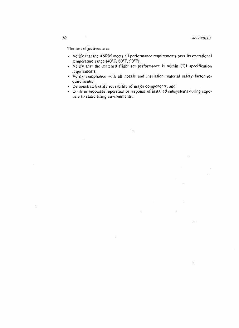
50 APPENDIX A
The test objectives are:
• Verify that the ASRM meets all performance requirements over its operationaltemperature range (40°F, 60°F, 90°F);
• Verify that the matched flight set performance is within CEI specificationrequirements;
• Verify compliance with all nozzle and insulation material safety factor re-quirements;
• Demonstrate/certify reusability of major components; and• Confirm successful operation or response of installed subsystems during expo-
sure to static firing environments.

Appendix B
Nondestructive Evaluation Methods
Electromagnetic Acoustic Transducer (EMAT): Detects surface and subsur-face anomaliesEddy Current Test (ET): Detects surface and subsurface anomaliesFourier Transform Infrared Spectroscopy (FTIR): Identifies organic substances,particle size, and quantitative analysis of mixtures.Leak Test (LT): Verifies O-ring seal integrityMagnetic Particle Test (MT): Detects surface and near surface anomaliesOptically Stimulated Electron Emission (OSEE): Detects surface contamina-tionPenetrant Test (PT): Detects surface anomaliesRadiography Test (RT): Detects surface and subsurface anomaliesReal-Time Radiography (RTR): Detects surface and subsurface anomaliesUltrasonic Test (UT): Detects surface and subsurface anomaliesX-ray Fluorescence (XRF or FA): Allows bulk qualitative and quantitativeanalysis of solids and liquids

Appendix C
Component NDE Methods
52
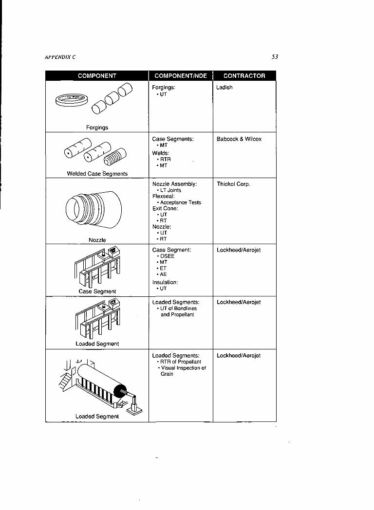
APPENDIX C 53
COMPONENT COMPONENT/NDE CONTRACTOR
Forgings
Forgings:•UT
Ladish
Welded Case Segments
Case Segments:•MT
Welds:•RTR•MT
Babcock & Wilcox
Nozzle
Nozzle Assembly:• LT Joints
Flexseal:• Acceptance Tests
Exit Cone:•UT•RT
Nozzle:•UT•RT
Thiokol Corp.
Case Segment
Case Segment:•OSEE•MT•ET• AE
Insulation:•UT
Lockheed/Aerojet
Loaded Segment
Loaded Segments:• UT of Bondlines
and Propellant
Lockheed/Aerojet
Loaded Segment
Loaded Segments:• RTR of Propellant• Visual Inspection ofGrain
Lockheed/Aerojet

Appendix D
Schematic of ASRM Test Program
54
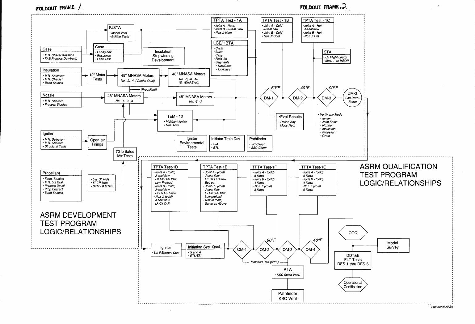
HOLDOUT FRAME /. F0LDOUT FRAMIcQ.
t
Case• MTL Characterization• FAB Process Dev/Verif.
Insulation• MTL Selection• MTL Charact.• Bond Studies
Nozzle• MTL Charact.• Process Studies
Igniter• MTL Selection• MTL Charact.• Structural Tests
Propellant• Form. Studies• MTL Lot Eval.• Process Devel.• Prop Charact.• Bond Studies
^ FJSTA• Model Verif.• Bolting Tests
• O-ring dev.* • Response
• Leak Test
TPTA Test - 1 A TPTA Test - 1 B TPTA Test - 1 C• Joint A - Nom. • Joint A - Cold • Joint A - Hot• i Iflint B - J-sf>al Flaw .l-seal flaw .l-Kf>al flaw• Noz Jt-Nom.
LCE/HBTA• Cycle
Insulation -BurstStripwindinq • CaseDevelopment -neiajts
• Segments1 • Noz/Case
1 I I 1 III 1 1 ign/uase \-k. 12" Motor fe. 4ft" MM A<; A *«-*—- 1 — 48" MNASA Motors
Tests No .2 _4 (Ven
(
^ 48" MNASA MotorsNo. -1, -2, -3
^
dor Qual) .̂' Wind Eval.)
Propellant)
^ 4ft" MNASA Motors , ,No. -5, -7
I -" TEM-10J
^ Oppn-air
Firings
70 Ib BatesMtr Tests
""" • Multiport Igniter• Noz. Mils.
• Joint B - Cold • Joint B - Hot• Noz Jt Cold • Noz Jt Hot
STAi, • (lit Flight /rw'<;
• Max. ~1.4x MEOP
fin°F AO°P QD°Px\ x\ x\ /*/ \v / NV / X. /DM-3\
' \ UM-l / \ LJM-^ / x L/M-o / 1 Lno uevei. 1
\ / \ / X / \ Phase /
* verity 3nv Mods ^1 -Eval Results -tgnit&• Define Any • Joint SealsMods Nee. • Nozzle
• Insulation• Propellant
Igniter Initiator Train Dev. PathfinderEnvironmental ,S/A -YC Ckout
Tests • ETL • SSC Ckout
• Liq. Strands. c» rp Mtr"
• BTM - 6 MTRS ,
ASRM DEVELOPMENTTEST PROGRAMLOGIC/RELATIONSHIPS
TPTA Test-ID TPTA Test-IE TPTATesMF TPTATesMG ASRM QUALIFICATION• Joint A - (cold) • Joint A - (cold) • Joint A - (cold) • Joint A - (cold) T f— O T" OO /~\ /^ l~> A It KJ-sealflaw J-sealflaw 5 flaws 6 flaws \ CO 1 r nUVJIllAMLKCkO-Hflaw LKCkO-Flflaw • Joint B - (cold) • Joint B - (cold) ^^^ ^ .. ^. ..^^Low Preload Boltout 4 flaws 4 flaws LOG C/RELAT ONSH PS
p • Joint B - (cold) • Joint B - (cold) • Noz Jt (cold) • Noz Jt (cold) I_W^>IIW/I ii_i_/-\i i\^iv\ji ill \JJ-sealflaw J-sealflaw 3 flaws 6 flawsLkCk O-R flaw LkCk O-R flaw
• Noz Jt (cold) Low preloadJ-seal flaw • Noz Jt (cold)Lk Ck O-R Same as Above
/\
^ loniter Initiation Sys. Qual. , /1..N,,^ a ISI ' • x QM-1 V*-• Lot 5 Environ. Qual -Sand A \ /
• ETUTBI \ /
'--- Ma
<^ COQ \
/^\"~ /\ S\°h Model
/QM-2\VQM-3\VQM-4\ *^
\/ \/ \/ DDT&E
tched Part (60°F) — T T nptflll TeSnrQ ADFS-1 thru DFS-6ATAM 1 M
• KSC Stack Verif.
./OperationalX.\Certification /\ /
PathfinderKSC Verif
Courtesy ol NASA

NATIONAL ACADEMY PRESSThe National Academy Press was created by theNational Academy of Sciences to publish the reportsissued by the Academy and by the National Academyof Engineering, the Institute of Medicine, and theNational Research Council, all operating under thecharter granted to the National Academy of Sciencesby the Congress of the United States.