Embed Size (px)
Citation preview

This content has been downloaded from IOPscience. Please scroll down to see the full text.
Download details:
IP Address: 130.126.255.92
This content was downloaded on 03/12/2015 at 17:06
Please note that terms and conditions apply.
The spinning ball spiral
View the table of contents for this issue, or go to the journal homepage for more
2010 New J. Phys. 12 093004
(http://iopscience.iop.org/1367-2630/12/9/093004)
Home Search Collections Journals About Contact us My IOPscience

T h e o p e n – a c c e s s j o u r n a l f o r p h y s i c s
New Journal of Physics
The spinning ball spiral
Guillaume Dupeux, Anne Le Goff, David Quéréand Christophe Clanet1
PMMH, UMR7636 du CNRS, ESPCI, 10 rue Vauquelin, 75005 Paris, FranceandLadHyX, UMR7646 du CNRS, Ecole Polytechnique, 91128 Palaiseau, FranceE-mail: [email protected]
New Journal of Physics 12 (2010) 093004 (12pp)Received 3 March 2010Published 2 September 2010Online at http://www.njp.org/doi:10.1088/1367-2630/12/9/093004
Abstract. We discuss the trajectory of a fast revolving solid ball moving in afluid of comparable density. As the ball slows down owing to drag, its trajectoryfollows an exponential spiral as long as the rotation speed remains constant:at the characteristic distance L where the ball speed is significantly affectedby the drag, the bending of the trajectory increases, surprisingly. Later, therotation speed decreases, which makes the ball follow a second kind of spiral,also described in the paper. Finally, the use of these highly curved trajectories isshown to be relevant to sports.
Contents
1. Introduction 22. Experimental facts 23. Model 5
3.1. Drag . . . . . . . . . . . . . . . . . . . . . . . . . . . . . . . . . . . . . . . . 53.2. Lift . . . . . . . . . . . . . . . . . . . . . . . . . . . . . . . . . . . . . . . . 53.3. The ideal spiral . . . . . . . . . . . . . . . . . . . . . . . . . . . . . . . . . . 73.4. Variation in the rotation speed . . . . . . . . . . . . . . . . . . . . . . . . . . 83.5. The ‘real’ spiral . . . . . . . . . . . . . . . . . . . . . . . . . . . . . . . . . . 9
4. Application to sports 95. Conclusions 10References 11
1 Author to whom any correspondence should be addressed.
New Journal of Physics 12 (2010) 0930041367-2630/10/093004+12$30.00 © IOP Publishing Ltd and Deutsche Physikalische Gesellschaft

2
1. Introduction
Since Galileo, spheres have been used by physicists to probe movement and friction [13, 14, 27].In the context of hydrodynamics, in particular, the motion of a solid sphere (radius R, velocityU0, density ρs) in a quiescent liquid (viscosity η, density ρ) is the paradigm for characterizingthe laws of friction at low and high Reynolds numbers.
For low Reynolds number (Re = ρU0 R/η � 1), Stokes [30] established that the drag forceexperienced by the solid during its motion is F = 6πηU0 R. This very classical result was thenverified by several authors in the range Re < 1 [8, 24]. For high Reynolds numbers, Newton [22]was probably the first to propose an heuristic expression for the drag: F = 1/2CDρU 2
0 π R2,where CD is a coefficient provided by the experiments. According to Eiffel [12], CD isof the order of 0.4, a value later confirmed in the range 103 < Re < 2 × 10⁵ [28]. Forintermediate Reynolds numbers (1 < Re < 103), the asymptotic expansion method proposed byOseen [23] led to lots of theoretical developments [4]. Beyond Re ≈ 2 × 10⁵, the resistancecrisis experienced by the sphere once the boundary layer becomes turbulent has also beenstudied in depth [1, 17, 29].
For spinning spheres, according to Barkla and Auchterloniet [2], the work seems to go backto Robins [25] and then Magnus [18], who got the credit for the associated lift force. Besidesthese academic studies, the widespread use of balls in sports also motivated many studies, inbaseball [21] and golf [9] in particular, a review of which can be found in [20]. Most of thesestudies consider a lift force FL = 1/2CLρU 2
0 π R2, where the lift coefficient CL is known toincrease with the spin parameter S = Rω0/U0.
Here, we study the trajectory of spinning spheres in water and try to understand theirsurprisingly curved trajectory, an example of which is presented in figures 1 and 2. In figure 1,the trajectory is decomposed into eight images, whereas in figure 2, the same sequence ispresented within a single image by superimposing the successive positions of the ball. Bothfigures reveal a spiral trajectory. With solid friction and rotation, similar curved trajectoriescan be obtained, for example in French billard [6] and in lawn bowls [7]. In figure 2, we alsoobserve the formation of an air cavity behind the sphere, a consequence of the high speed ofpenetration [5, 10, 11, 15, 16, 19, 32]. The bending of the trajectory starts as soon as the ballenters the bath, as reported in [31] for vertical impacts. Our aim here is to focus on the spiraltrajectory and to discuss its relevance to sports.
2. Experimental facts
The projectiles used in this study are balls made of either polypropylene (ρs ' 920 kg m−3) orpolyacetal (ρs ' 1400 kg m−3), a few millimetres in size. Spin and high velocities (20–50 m s−1)are achieved using a slingshot, consisting of a forked stick attached to a pocket by two rubberstrips. The velocity can be varied by tuning the average tension applied to the rubbers, whereasthe spin is controlled by the difference in tension between them: the motion is a pure translationwhen the extension of the two arms is symmetric, and spinning occurs when one strip is morestretched than the other. Both translational and spin velocities at the moment of impact U0 andω0 are measured on the images recorded with a high speed video camera. Rotation is madevisible by drawing a line on the equator and illuminating the spheres.
The effect of spin is illustrated in figure 3. Without rotation (ω0 = 0), the ball goes straight(figure 3(a)). With a bottom spin (ω0 > 0), figure 3(b) shows that the ball deviates upwards;
New Journal of Physics 12 (2010) 093004 (http://www.njp.org/)

3
Figure 1. Chronophotography of the impact of an iso-density sphere (R =
3.5 mm) penetrating a bath of water at U0 = 35 m s−1 and spinning at ω0 ≈
1200 rad s−1. The time step between images is not constant. t = 0 is the impacttime, t1 = −0.5 ms, t2 = 2.8 ms, t3 = 13 ms, t4 = 42 ms, t5 = 76 ms, t6 = 101 ms,t7 = 169 ms and t8 = 216 ms. The arrows indicate the sphere velocity.
Figure 2. Multi-pose image showing the trajectory of the ball of figure 1. Thetime step between successive ball locations is 1t = 10 ms. This image reveals aspiral trajectory.
it is even able to escape from the bath (last two images). Finally, for top spin (ω0 < 0), theball deviates downwards (figure 3(c)). We focus now on the bottom spin case and show infigure 4(a) the trajectory of a polypropylene ball (ρs/ρ = 0.92) of radius R = 3.5 mm thrownin a water bath at a velocity U0 = 27 m s−1, with a spin rate ω0 = 1000 rad s−1 and an impactangle θ0 = 70◦ (defined from the vertical). In this trajectory, the constant time step betweentwo data is 1t = 384 µs. Clearly, the velocity of the ball decreases as it moves through water(figure 4(a)). The evolution of the ball velocity is reported in figure 4(b) as a function of thecurvilinear location s (s = 0 at impact). The semi-log presentation stresses that the velocitydecreases exponentially with s. The characteristic length of the decrease is here 5.5 cm. Despite
New Journal of Physics 12 (2010) 093004 (http://www.njp.org/)

4
Figure 3. Effect of spin on the trajectory of a sphere (density ρs) after impactin water: (a) U0 = 33 m s−1, R = 3.5 mm, ρs = 1410 kg m−3, ω0 = 0 rad s−1,time step between images 1t = 2 ms. (b) U0 = 20 m s−1, R = 2.4 mm, ρs =
920 kg m−3, ω0 = 1740 rad s−1, 1t = 3.75 ms. (c) U0 = 24 m s−1, R = 2.4 mm,ρs = 920 kg m−3, ω0 = −1740 rad s−1, 1t = 3.2 ms. The trajectory bends only ifspin is present and the sign of its curvature changes with the sign of the spin.
-10
-8
-6
-4
-2
0
2
-2 0 2 4 6 8 10
0 s( )
x cm( )
y cm( )
1
10
100
-2 0 2 4 6 8 10
U m/s( )
s cm( )
100
1000
104
0 1 2 3 4 5 6 7 8
rad/s( )
t ms( )
(a) (b) (c)
Figure 4. (a) Trajectory of a ball (radius R = 3.5 mm, density ρs = 920 kg m−3)impacting water with a velocity U0 = 27 m s−1, a spin ω0 = 1000 rad s−1 andan inclination angle θ0 = 70◦. The time step between two data points is1t = 384 µs. (b) Evolution of the corresponding velocity as a function of thecurvilinear location s in a semi-log plot. (c) Time variation of the correspondingrotation speed ω of the ball.
New Journal of Physics 12 (2010) 093004 (http://www.njp.org/)

5
a strong variation in the velocity, the spin rate ω remains almost constant as the ball movesthrough water, as demonstrated in figure 4(c). This difference is discussed in the followingsection and is shown to be the key fact to account for the spiral trajectory.
3. Model
3.1. Drag
The motion of the sphere of mass M is described in the Serret–Frenet coordinate system (t, n)
introduced in figure 2. We first focus on the direction t . The Reynolds number Re = ρU0 R/η
is of the order of 104, which implies a drag F ≈ 1/2ρU 2π R2· CD, with CD ≈ 0.4 [28]. The
equation of motion along t thus is written as
M
(1 + CM
ρ
ρs
)U
dU
ds= −
1
2ρU 2π R2
· CD. (1)
In this equation, CM stands for the added mass coefficient, which, for a sphere, is of the order of1/2, independent of the speed U [3]. Using the condition U (s = 0) = U0, equation (1) can beintegrated as
U (s) = U0 e−s/L (2)
with
L=8 ρ̄
3 CDR with ρ̄ =
(1 + CM
ρ
ρs
)ρs
ρ. (3)
The velocity thus decreases exponentially in water, with a characteristic penetration lengthL≈ 7ρ̄R ≈ 10R. This behaviour agrees with the results displayed in figure 4(b). We deducefrom such measurements the value of L for different systems. Our data are presented in figure 5as a function of the length ρ̄R and compared to the results obtained by May [19] and Truscottand Techet [31]. All the data collapse in the same curve, L≈ 7ρ̄R, in good agreement withequation (3). This comparison underlines that the entrained air cavity visible in figures 1–3 doesnot significantly affect the drag on the sphere. The time variation of the velocity can finally bededuced from equation (1), which classically yields U (t) = U0/(1 + t/τ), where τ = L/U0 isthe characteristic slowing time of the ball.
In equation (1) and in the above discussion, we neglected the effect of gravity. Thisassumption remains valid as long as the drag F is large compared to the Archimedean force4π/3(ρs − ρ)gR3. Using the expression for the drag, we conclude that the low gravity regimeis achieved as long as U � U∗, where U ∗2
= 8/3CD|ρs/ρ − 1|gR. This condition is alwaysfulfilled in the iso-density case but it fails otherwise at the ‘end’ of the trajectory, when thevelocity of the ball vanishes. In this paper, we focus on the hydrodynamic effects and do notaddress the classical gravitational problem. Our conclusions thus hold above the critical speedU∗, which in our case (ρs/ρ ≈ 1.2, R ≈ 4 mm) is approximately 10 cm s−1, much smaller thanthe impact speeds (≈10 m s−1).
3.2. Lift
Along the direction n, the equation of motion can be written as
M
(1 + CM
ρ
ρs
)U 2 dθ
ds= FL, (4)
New Journal of Physics 12 (2010) 093004 (http://www.njp.org/)

6
Figure 5. (a) Characteristic length of penetration L as a function of ρ̄R. Thesymbols � and � show the results of May [19] and Truscott and Techet [31],respectively. The symbol� is used for our results. Equation (3), that is L≈ 7ρ̄R,is represented by the solid line. (b) Initial curvature (dθ/ds)0 of the ball trajectoryas a function of ω0/U0 · 1/ρ̄. The symbol � is used for the data of Truscott andTechet [31] and the symbol � for our results. The solid line shows the fit of(dθ/ds)0 = 0.14ω0/U0 · 1/ρ̄.
where FL = ρ0U RCn is the lift force resulting from the circulation 0 = 2π R2ω. In the limit oflow Reynolds numbers (Re < 1), Rubinow and Keller [26] have shown that we have Cn = 1/2.For large Reynolds numbers (Re ≈ 105), Nathan [21] collected the data obtained by severalauthors on the lift force experienced by spinning balls in air. From these results, we deduceCn ≈ 0.13.
Since our experiments are done in water with an entrained air cavity, we found it useful tomeasure Cn. For this purpose, we focused on the impact region (s < L), where the dynamicalparameters (U, ω) are constant, so that equation (4) predicts a constant curvature for the balltrajectory, (
dθ
ds
)0
=3
2
Cn
ρ̄
ω0
U0. (5)
This initial curvature is presented in figure 5(b) as a function of the inverse length ω0/ρ̄U0 (�).In the same figure, we also report the data extracted from Truscott and Techet [31] (�).Equation (5) nicely predicts the initial curvature of the trajectory, and the best fit on both sets ofdata suggests Cn ≈ 0.1, a value comparable to the one deduced from Nathan [21]. There again,the air cavity behind the ball does not affect the evaluation of the lift, a consequence of theentrainment of a water boundary layer around the projectile.
New Journal of Physics 12 (2010) 093004 (http://www.njp.org/)

7
C
Figure 6. Characteristics of the ideal spiral for a spinning ball: the trajectory ofthe ball is plotted in the plane (x, y) for U0 = 32 m s−1, R = 3.6 mm, θ0 = 67◦,ω0 = 743 rad s−1 and ρs/ρ = 1.4. The experimental data are presented with the� symbol, while the theoretical shape (equation (6)) is drawn with a solid thinline (y = 0 is the surface of the water bath).
3.3. The ideal spiral
The next step in the derivation of the ball trajectory is to assume that the circulation 0 remains(almost) constant during the motion, that is, over timescale τ . This assumption is suggested byfigure 4(c) and we discuss it further in section 3.4. Then, for 0 = 2π R2ω0, equation (4) togetherwith (2) implies
θ(s) = θ0 + 1S[es/L
− 1], (6)
where 1 = 4Cn/CD ≈ 1 and S = ω0 R/U0. The deviation of the ball from its initial orientationθ0 thus increases exponentially with the curvilinear coordinate s, which defines the spinning ball(ideal) spiral. The characteristic lengthL for which the spiral coils up precisely is the penetrationlength expressed by equation (3).
We compare in figure 6 the observed trajectory (�) to equation (6) (solid line). Thecomparison is made in the plane (x, y) using the geometrical relations dx/ds = sin θ ,dy/ds = −cos θ and for S ≈ 0.09, the value of the spin parameter in this experiment. Thetheoretical prediction is in close agreement with the experimental path up to the point wherethe ball escapes from the bath, whose surface is defined by y = 0.
An ideal spiral would converge to a centre C (figure 6) located at a distance D from theimpact point. Since C is approached when θ(s) − θ0 is of the order of π (corresponding to aU-turn of the ball), we obtain from equation (6) D ≈ L ln[1 + π/1S]. The distance D is a linearfunction of L and slowly diverges (as ln 1/S) when the spin number goes to 0. Conversely,for large spin numbers, the spiral centre is expected to converge towards the impact location(D ≈ L/S).
New Journal of Physics 12 (2010) 093004 (http://www.njp.org/)
8
0
0,1
0,2
0,3
0,4
0,5
0,6
0,7
0,8
0 0,01 0,02 0,03 0,04 0,05 0,06 0,07 0,08
t (s)
0 1
(a) (b)
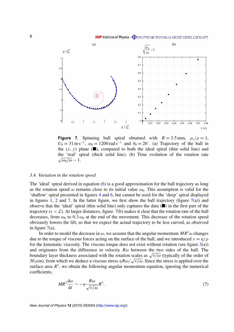
Figure 7. Spinning ball spiral obtained with R = 3.5 mm, ρs/ρ = 1,U0 = 31 m s−1, ω0 = 1200 rad s−1 and θ0 = 26◦. (a) Trajectory of the ball inthe (x, y) plane (�), compared to both the ideal spiral (thin solid line) andthe ‘real’ spiral (thick solid line). (b) Time evolution of the rotation rate√
ω0/ω − 1.
3.4. Variation in the rotation speed
The ‘ideal’ spiral derived in equation (6) is a good approximation for the ball trajectory as longas the rotation speed ω remains close to its initial value ω0. This assumption is valid for the‘shallow’ spiral presented in figures 4 and 6, but cannot be used for the ‘deep’ spiral displayedin figures 1, 2 and 7. In the latter figure, we first show the ball trajectory (figure 7(a)) andobserve that the ‘ideal’ spiral (thin solid line) only captures the data (�) in the first part of thetrajectory (s < L). At larger distances, figure 7(b) makes it clear that the rotation rate of the balldecreases, from ω0 to 0.3 ω0 at the end of the movement. This decrease of the rotation speedobviously lowers the lift, so that we expect the actual trajectory to be less curved, as observedin figure 7(a).
In order to model the decrease in ω, we assume that the angular momentum MR2ω changesdue to the torque of viscous forces acting on the surface of the ball, and we introduced ν = η/ρ
for the kinematic viscosity. The viscous torque does not exist without rotation (see figure 3(a))and originates from the difference in velocity Rω between the two sides of the ball. Theboundary layer thickness associated with the rotation scales as
√ν/ω (typically of the order of
30 µm), from which we deduce a viscous stress ηRω/√
ν/ω. Since the stress is applied over thesurface area R2, we obtain the following angular momentum equation, ignoring the numericalcoefficients,
MR2 dω
dt∼ −η
Rω√
ν/ωR3. (7)
New Journal of Physics 12 (2010) 093004 (http://www.njp.org/)

9
Equation (7) can be integrated, which leads to the time evolution of ω,
ω
ω0=
1
(1 + t/τω)2 , where τω =1
β
ρs
ρ
R√
ω0ν. (8)
The spin velocity of the ball thus decreases over a characteristic time τω (where β is a numericalconstant, whose value is discussed below). The trajectory remains close to the ideal spiral aslong as the travelling time t (s) = τ(es/L
− 1) is smaller than τω (we recall that τ = L/U0). Onethus expects to leave the ideal spiral when s becomes larger than L ln[1 + U0/
√ω0ν ], that is, a
few times L, as observed in figure 7.Conversely, if τω < τ , ω decreases quicker than needed to make the spiral, and the
corresponding lift force vanishes before curving the trajectory. One thus expects a linearpropagation of the ball in this limit, which corresponds to impacts in viscous liquids (ν >
U 20 /ω0). For the parameters in our experiments (U0 ≈ 30 m s−1; ω0 ≈ 1000 rad s−1), this limit
corresponds to oils at least 1000 times more viscous than water.
3.5. The ‘real’ spiral
In order to account for the variation in the spin rate during the ball motion, we re-write theequation of motion along the n-direction (4) as an equation for the curvature,
dθ
ds=
1S
Les/L ω
ω0. (9)
Since ω/ω0 = 1/(1 + τ/τω(es/L− 1))2, this equation can be integrated, which yields
θ(s) = θ0 + 1Ses/L
− 1[1 + τ
τω(es/L− 1)
] . (10)
In the limit τ/τω � 1, the evolution of the local angle reduces to the ideal spiral (6). However,even if τ/τω is small, its product with the exponential term es/L can lead to an observable effectof the spin decrease. For β = 3.1, the trajectory obtained with equation (10) is drawn with athick solid line in figure 7(a), showing fair agreement with the data. At long distances, equation(10) predicts that the ball follows a straight line, deviating from the impact direction by an angle1Sτω/τ proportional to the spin number S.
4. Application to sports
The physical origin of the spinning ball spiral lies in the difference in velocity dependencesof lift and drag, which are linear and quadratic, respectively. This behaviour is specific to highReynolds number flows around spinning spheres. In our experiments, we used water to minimizethe effect of gravity and to reduce the spatial scale of the spiral L∼ ρ̄R. However, the spinningball spiral should also exist in air, and we discuss here its influence in ball games.
For different sports, table 1 shows the ball size, the density ratio, the maximum ballvelocity, the characteristic spin parameter and the size of the field, L . In the special case ofbaseball, L represents the distance between the pitcher and the batter. Using these data, wealso display the penetration length L= 7ρ̄R and the length scale U 2
0 /g on which gravity acts.By comparing L and U 2
0 /g, one can identify sports dominated by aerodynamics (table tennis,golf and tennis) and sports dominated by gravity (basketball and handball). In between, we
New Journal of Physics 12 (2010) 093004 (http://www.njp.org/)

10
Table 1. Specifications for different sports. The first three sports are dominatedby aerodynamic effects (L� U 2
0 /g). For the last two sports, gravity dominatesaerodynamics (L� U 2
0 /g). In between, we identify sports for which both gravityand aerodynamics can be used to control the ball’s trajectory. In this table, L isthe size of the field except for baseball, where it stands for the distance betweenthe pitcher and the batter.
2R ρs/ρ U0 L L U 20 /g d
Sport (cm) (m s−1) S = Rω0/U0 (m) (m) (m) (m)
Table tennis 4.0 67 50 0.36 2.7 9.3 255 1Golf 4.2 967 90 0.09 200 141 826 7Tennis 6.5 330 70 0.19 24 73 499 5Soccer 21 74 30 0.21 100 54 92 7Baseball 7.0 654 40 0.17 18 160 163 7Volleyball 21 49 20 0.21 18 35 41 5Basketball 24 72 10 28 60 10Handball 19 108 20 40 71 40
find sports where both gravity and aerodynamics play a comparable role (soccer, volleyball andbaseball). Indeed, in the first category of sports, the spin is systematically used, while it is notrelevant in the second category, and it only appears occasionally in the third one, in order toproduce surprising trajectories.
Focusing on sports where aerodynamics plays a role, we observe that the penetrationlength, which is also the characteristic length of the spiral, is generally larger than the sizeof the field. Since the spin parameter is smaller than one, the spiral centre (section 3.3) will lieoutside the field. This suggests that the ball trajectory (6) can be expanded for s/L� 1. In thislimit, the spiral reduces to a circle of curvature (5), and we can evaluate the length d by whichthe ball deviated from its initial direction by its own size R: d ≈
√2LR/1S. This distance is
shown in the last column of table 1. It is found to be systematically smaller than L , the fieldsize, which makes relevant the use of spin effects to control the trajectory of the ball.
The case of soccer, where L is twice as small as L , is worth commenting on. The balltrajectory can deviate significantly from a circle, provided that the shot is long enough. Thenthe trajectory becomes surprising and somehow unpredictable for a goalkeeper. This is the waywe interpret a famous goal by the Brazilian player Roberto Carlos against France in 1997(http:// www.youtube.com/watch?v=crSkWaJqx-Y). This free kick was shot from a distanceof approximately 35 m, that is, comparable to the distance L for which we expect this kindof unexpected trajectory. Provided that the shot is powerful enough, another characteristic ofRoberto Carlos’ abilities, the ball trajectory brutally bends towards the net, at a velocity stilllarge enough to surprise the keeper.
5. Conclusions
We have studied the motion of spinning spheres at high Reynolds number and in the limit of lowgravity. In this regime, we showed that the curvature of the ball trajectory changes as it moves,
New Journal of Physics 12 (2010) 093004 (http://www.njp.org/)
11
following law (9), rewritten here as
dθ
ds∼
ω(s)
U (s)·
1
ρ̄. (11)
We have identified the characteristic length L∼ 7ρ̄R over which the ball slows down and coils.Using this length, we have classified different phases in the ball trajectory. (i) In the initialphase (s/L� 1), neither the velocity nor the spin varies, and the ball follows a circular pathwhose curvature C0 can be deduced from (11): ω0/ρ̄U0. (ii) As s approaches L, the velocity ischanged but the spin is only weakly affected. This difference in behaviour is all the larger sincedimensionless number
√ω0ν/U0 is small. In this phase (s/L≈ 1), the spinning ball coils up
and forms a spiral. (iii) The last phase of the flight is reached when both the velocity and thespin decrease (s/L> 1). The trajectory then deviates from the spiral and tends to a straight lineas the ball stops.
References
[1] Achenbach E 1972 Experiments on the flow past spheres at very high Reynolds numbers J. Fluid Mech.54 565–75
[2] Barkla H M and Auchterloniet L J 1971 The Magnus or Robins effect on rotating spheres J. Fluid Mech.47 437–47
[3] Batchelor G K 1967 An Introduction to Fluid Dynamics (Cambridge: Cambridge University Press)[4] Benjamin T B 1993 Note on formulas for the drag of a sphere J. Fluid Mech. 246 335–42[5] Bergmann R P H M, van der Meer D, Gekle S, van der Bos J A and Lohse D 2009 Controlled impact of a
disk on a water surface: cavity dynamics J. Fluid Mech. 633 381–409[6] Coriolis G 1835 Théorie Mathématique des Effets du Jeu de Billard (Paris: Jacques Gabay Editeur) http://
gallica.bnf.fr/ark:/12148/bpt6k29318f.image.f1[7] Cross R 1998 The trajectory of a ball in lawn bowls Am. J. Phys. 66 735–8[8] Davies C N 1945 Proc. Phys. Soc. 57 259[9] Davies J M 1949 The aerodynamics of golf balls J. Appl. Phys. 20 821–8
[10] Duclaux V, Caille F, Duez C, Ybert C, Bocquet L and Clanet C 2007 Dynamics of transient cavities J. FluidMech. 591 1–19
[11] Duez C, Ybert C, Clanet C and Bocquet L 2007 Making a splash with water repellency Nature Phys. 3 180–3[12] Eiffel G 1909 Recherches expérimentales sur la résistance de l’air exécutées à la tour Eiffel (Paris: Librarie
aéronautique) http://gallica.bnf.fr/ark:/12148/bpt6k5675046x.zoom.r=Eiffel.f11.langFR[13] Galilei G 1638 Dialogues Concerning Two New Sciences (New York: Dover) http://gallica.bnf.fr/ark:/12148/
bpt6k512641.image.f2.langFR[14] Geiger H and Marsden E 1909 On a diffuse reflection of the α-particles Proc. R. Soc. A 82 495–500[15] Glasheen J W and McMahon T A 1996 A hydrodynamic model of locomotion in the basilisk lizard Nature
380 340–2[16] Lohse D 2003 Bubble puzzles Phys. Today 56 36–41[17] Lyotard N, Shew W L, Bocquet L and Pinton J-F 2007 Polymer and surface roughness effects on the drag
crisis for falling spheres Eur. Phys. J. B 60 469–76[18] Magnus G 1853 Über die Abweichung der Geschosse, und: Über eine abfallende Erscheinung bei rotirenden
Körpern Annalen der Physik 164(1) 1–29[19] May A 1950 The virtual mass of a sphere entering water vertically J. Appl. Phys. 21 1285–9[20] Metha D 1985 Aerodynamics of sports balls Annu. Rev. Fluid Mech. 17 151–89[21] Nathan A M 2008 The effect of spin on the flight of a baseball Am. J. Phys. 76 119–24[22] Newton I 1687 Philosophiæ Naturalis Principia Mathematica lib. 2 prop. 33
New Journal of Physics 12 (2010) 093004 (http://www.njp.org/)
12
[23] Oseen C W 1910 Über die Stokes’sche Formel, und über eine verwandte Aufgabe in der HydrodynamikArk. Math. Astronom. Fys. 6 No. 27
[24] Pruppacher H R 1968 An experimental determination of the drag on a sphere at low Reynolds numbersJ. Appl. Phys. 39 4129–32
[25] Robins B 1805 New Principles of Gunnery ed R Hutton (first printed in 1742)[26] Rubinow S I and Keller J B 1961 The transverse force on a spinning sphere moving in a viscous fluid J. Fluid
Mech. 11 447–59[27] Rutherford E 1906 Phil. Mag. Ser. 6 12 143[28] Schlichting H 1955 Boundary-Layer Theory (New York: McGraw-Hill)[29] Smith M R, Hilton D K and Van Sciver S W 1999 Observed drag crisis on a sphere in flowing He I and He II
Phys. Fluids 11 751–3[30] Stokes G G 1851 On the effect of internal friction of fluids on the motion of pendulums Trans. Camb. Phil.
Soc. 9 8–106[31] Truscott T T and Techet A H 2009 Water entry of spinning spheres J. Fluid Mech. 625 135–65[32] Worthington A M and Cole R S 1900 Impact with a liquid surface studied by the aid of instantaneous
photography. Paper II Phil. Trans. R. Soc. A 194 175–99
New Journal of Physics 12 (2010) 093004 (http://www.njp.org/)