Embed Size (px)
Citation preview
316
THE STABILITY AND CONTROL OF MOTORCYCLES By R. S. Sharp*
Mathematical models of a motorcycle and rider dependent on three alternative assump- tions concerning the tyre behaviour are developed. Stability characteristics deduced from them are compared, and minimum requirements for the model greater than have been previously satisfied are established. Using the most sophisticated of the models, the effects
of design changes are calculated, and the design implications are discussed.
INTRODUCTION THEORETICAL STUDIES of the steering behaviour of auto- mobiles after Segel (I)t have transformed understanding of the subject and provided valuable design information and design evaluation techniques. Parallel studies relating to two wheeled vehicles (2)-(5) have been comparatively unsuccessful, and motorcycle design at present relies on experience rather than understanding for its success.
A viable theory of motorcycle stability and control must be consistent with the practically obvious instability of the machine at very low speeds, with the possibility of ‘hands off’ control (i.e. control without the direct application of steering torque) at moderate speeds, and with the possible ociurrence of oscillatory instabilities at high speeds. These were described by Pearsall (3) as ‘speedman’s wobble’. It should also provide some explanation for current design practice, mindful that it should be converging on some evolutionary optimum, and ideally it should support the empirical maxims of motorcycle design (e.g. the mass centre should be as low as possible and as far forward as possible).
In the case of the car, Segel (6) has observed that different drivers employ different proportions of fixed and free control, and that particular drivers can alter these proportions to suit the car which they are driving. In the case of the motorcycle, the free control behaviour would appear to be relatively much more important, since the very small steer angles normally employed (7) would make fixed control difficult, and since in the ‘hands off’ condi- tion the fixed control characteristics of the machine have no relevance to the motion.
Consequently, the work which is the subject of this paper was directed towards the development of a suitable mathematical model of a motorcycle in free control, and
The M S . of this paper was received a t the Institution on 10th August
* Lecturer, Department of Mechanical Engineering, Universitj! of
t References are given in Appendix 5 .
1970 and accepted for publication on 17th M a y 1971. 2
Leeds, Leeds, LS2 93T.
J O U R N A L M E C H A N I C A L E N G I N E E R I N G S C I E N C E
the use of such a model to show typical stability charac- teristics and how these characteristics depend on various parameter values. Also, in the light of Segel’s conclusion (6) that the steady state control force gradient is an im- portant parameter in determining car handling quality, and his statement that this is the case with aircraft too, the steady state behaviour has been studied. The model is easily applied to the fixed control case and appropriate results are included.
A particular difficulty in the analysis concerns the treatment of the tyre behaviour. Whipple (2), Pearsall (3), and Collins (5) allowed the tyres no sideslip freedom, while Kondo, Nagaoka and Yoshimura (4) allowed this freedom, but ignored the lag between the steering of a pneumatic tyred wheel and the building up of the side force towards a steady state value, which is of great im- portance in the wheel shimmy phenomenon (8). Results dependent on each of the three alternative assumptions regarding the tyre behaviour are included and compared.
i
Coefficient matrices.
Linear dimensions (Fig. 1).
Front and rear tyre cornering stiffnesses re-
Front and rear tyre camber stiffnesses re-
Rear frame product of inertia with respect to
Acceleration due to gravity. Front frame inertias about axes parallel to
OX4Y4Z4 (Fig. 2) through mass centre (assumed to be principal axes).
Rear frame inertias about axes parallel to O X , Y2Z2 (Fig. 2) through mass centre.
Polar moment of inertia of engine flywheel.
spectively.
spectively.
above axes.
Vol I3 No 5 1971
THE STABILITY AND CONTROL OF MOTORCYCLES 317
Polar moment of inertia of front wheel. Camber inertia of rear wheel. Polar moment of inertia of rear wheel. Steering damper coefficient. Mass of front frame. Mass of rear frame. Angular velocity components of front frame
Angular velocity components of rear frame
Generalized co-ordinate and force respec-
Components of forces Qxo and QYo along
Yawing velocity (= $). Sum of TI, T,, and T,, being the total system
kinetic energy. Kinetic energies of front and rear frames
(excluding wheel rotation) respectively. Extra kinetic energy accounting for wheel
rotation. Potential energies of front frame, rear frame,
and total system respectively. Lateral velocity of 0 (= Column matrix of amplitudes X,, X,, etc.
with respect to axes OX4Y4Z4 .
with respect to axes OX,Y,Z,.
tively.
O X , and O Y , respectively.
(XI X I , Y 2 Forces applied at front and rear tyre to road X,, Y,, I, Zr I> contact points respectively (Fig. 5). X I , X, Lateral velocity and yawing velocity ampli-
tudes respectively. x,, ko, yo, yo Co-ordinates and velocities of reference
point A in OX, YoZo system. il, xl,yl ,yl Velocities and accelerations of reference
point A in OX,Y,Z, system. Y’,, Y’, Steady state lateral tyre forces. UIY c(r Front and rear tyre sideslip angles respec-
tively. Y Effective front wheel steer angle (Fig. 6). A Steering velocity (= 6).
5 7 01, o r
A
CL Exponential coefficient. 0 1 , ur
E Steering head angle (Fig. 1). Velocity of front frame mass centre, GI. Velocity of rear frame mass centre, G,. Front and rear wheel angular position co-
Gear ratio between rear wheel and engine ordinates respectively.
flywheel.
Front and rear tyre relaxation lengths re- spectively.
7 Rider applied steering torque. @ Rolling velocity (= 4). 41 $4 4, 6
Front wheel camber angle (Fig. 6). Angular displacements (Fig. 2).
PHYSICAL DESCRIPTION OF MODEL The following assumptions are made regarding the repre- sentation of the vehicle. J O U R N A L M E C H A N I C A L E N G I N E E R I N G S C I E N C E
(1) The vehicle consists of two rigid frames joined at the steering axis with freedom, restrained by a linear steering damper, of the front frame to steer relative to the rear one.
(2) The front frame consists of the front wheel, forks, handlebars and fittings.
(3) The rear frame consists of the main structure, the engine-gearbox assembly, the petrol tank, seat, rear forks, rear wheel, etc., with rigidly attached rider.
(4) Each frame has a longitudinal plane of symmetry, and the axis through the front frame mass centre parallel to the steering axis is a principal one.
(5) The road wheels are rigid discs each making point contact with the road, and they roll without longitudinal slip on a flat level road surface.
(6) The axis of rotation of the engine flywheel is trans- verse.
(7) The machine moves at constant forward speed with freedom to sideslip, to yaw, and to roll; only small per- turbations from straight line running are considered.
(8) The air through which the machine moves is sta- tionary so that the effects of aerodynamic side force, yawing moment, and rolling moment, will be small com- pared with tyre effects. The effects of drag, lift and pitch- ing moment are to modify the vertical loading of the tyres, and to make necessary a longitudinal force at the driving wheel sufficient to maintain the constant forward speed assumed. These effects are accounted for by varia- tions in the coefficients relating tyre side forces to sideslip and camber angles.
(9) Pneumatic trail of the tyres is not considered since, for the rear tyre, its effect will be very small, and for the front tyre, it is small compared with the mechanical trail, and the effects of varying the mechanical trail itself are included in the results.
(10) The drag force at the front tyre is small compared with the tyre side forces.
The assumptions that the motorcycle with rigid wheels moves on a flat road surface and that is has no freedom to pitch are, strictly speaking, incompatible. As the handle- bars are turned, the front tyre to road contact point in general moves vertically and the problem is, in fact, treated as if the road surface moved vertically too to maintain contact. Bearing in mind the smallness of these vertical motions in normal running, and the fact that the tyre and suspension flexibilities and road irregularities have been ignored, this is considered to be a negligible extension of the above assumptions.
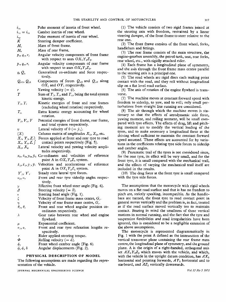
The motorcycle is represented diagrammatically in Fig. 1 with the point A defined as the intersection of the vertical transverse plane containing the rear frame mass centre, the longitudinal plane of symmetry, and the ground plane. A is the origin of a right-handed, orthogonal axis set AX,Y,Z, which moves with the vehicle, and which, with the vehicle in the upright datum condition, has A X , horizontal and pointing forwards, A Y , horizontal and to starboard, and AZ, vertically downwards.
Vol13 No 5 1971
318
Steer axis / R. S. SHARP
Fig. 1. Diagrammatic representation of the motorcycle
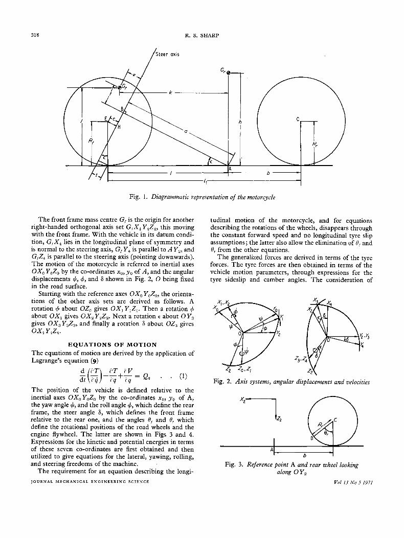
The front frame mass centre G, is the origin for another right-handed orthogonal axis set G,X4 Y,Z,, this moving with the front frame. With the vehicle in its datum condi- tion, G,X, lies in the longitudinal plane of symmetry and is normal to the steering axis, G, Y , is parallel to A Y,, and C,Z, is parallel to the steering axis (pointing downwards). The motion of the motorcycle is referred to inertial axes OXo YoZ, by the co-ordinates xo, y o of A , and the angular displacements $,4, and 6 shown in Fig. 2, 0 being fixed in the road surface.
Starting with the reference axes OX, YoZ,, the orienta- tions of the other axis sets are derived as follows. A rotation $I about OZ, gives OX,Y,Z,. Then a rotation 4 about O X , gives O X , Y,Z,. Next a rotation E about 0 Y2 gives OX,Y,Z,, and finally a rotation 6 about OZ, gives ox, Y4Z4.
EQUATIONS OF MOTION The equations of motion are derived by the application of Lagrange's equation (9)
c i ( L T ) LIT iV
d t iq ilq c q --+T- = Q, . . (1)
The position of the vehicle is defined relative to the inertial axes OXoYoZo by the co-ordinates xo, yo of A, the yaw angle $, and the roll angle 4, which define the rear frame, the steer angle 6, which defines the front frame relative to the rear one, and the angles 8, and Or which define the rotational positions of the road wheels and the engine flywheel. The latter are shown in Figs 3 and 4. Expressions for the kinetic and potential energies in terms of these seven co-ordinates are first obtained and then utilized to give equations for the lateral, yawing, rolling, and steering freedoms of the machine.
The requirement for an equation describing the longi- J O U R N A L M E C H A N I C A L E N G I N E E R I N G S C I E N C E
tudinal motion of the motorcycle, and for equations describing the rotations of the wheels, disappears through the constant forward speed and no longitudinal tyre slip assumptions; the latter also allow the elimination of 8, and Or from the other equations.
The generalized forces are derived in terms of the tyre forces. The tyre forces are then obtained in terms of the vehicle motion parameters, through expressions for the tyre sideslip and camber angles. The consideration of
Fig. 2. Axis systems, angular displacements and velocities
A b
A b
Fig. 3. Reference point A and rear wheel looking along O Y ,
Vol 13 No 5 1971
THE STABILITY AND CONTROL OF MOTORCYCLES
- 1 I -I2 - 1 3 - -14 - 1 5 - -16-
319
39. - i -
-
/Steer axis
Fig. 4. Front frame in datum condition looking along O Y ,
small perturbations from straight running allows the elimination of all second and higher order terms; the final equations of motion are linear.
The equations describing steady turning are obtained by elimination of the time varying terms, while the fixed control equations are obtained by omission of the steering degree of freedom. Details of the derivations are given in Appendix 1, while in Appendix 2 it is shown how the analysis can be restricted by the omission of tyre sideslip.
Solution of the equations The linear differential equations of motion in homo- geneous form, i.e. with T = 0, were reduced to a set of first order equations by the introduction of new variables 'u = j,, r = 6, @ = 4 and d = 8. Then, assuming solu- tions of the form v = X, cut, r = X 2 epf, etc. (11) and substituting these solutions back into the original equa- tions, a set of algebraic equations, which can be expressed in the matrix form ( B ) p ( X ) + ( A ) ( X ) = (0) results. Here, (B) and ( A ) are square coefficient matrices, while (X) is a column matrix of the unknown amplitudes X, , X,, etc.
Premultiplying by (B) - and rearranging,
- ( B ) - W ( X ) = P ( X ) and for non-trivial solutions for ( X ) , possible values of p must be eigenvalues of -(B)-l(A) (12). The real parts of the eigenvalues indicate the damping and the imaginary parts the natural frequencies associated with the various normal modes.
A numerical procedure was therefore employed for cal- culating the elements of the (A) and ( B ) matrices above from the design parameters for a particular machine and from its forward speed, forming -(B)-l(A), and finding its eigenvalues through a procedure employing the Q R algorithm (13). The linear steady state equations were solved by choosing a forward speed and roll angle and solving simultaneously for y,, 4, and 6, and then using the equation for the steering freedom to give T.
RESULTS The results fall into one of four categories which cover the following points.
(1) Natural frequencies and damping characteristics of one particular machine in free control according to the model which excludes tyre sideslip, the model which includes tyre sideslip but assumes instant tyre response and the model which includes the dynamics of tyre response.
(2) The effects of changes to the design of the machine in the model which includes the dynamics of the tyre response.
(3) The steady turning behaviour (at low lateral acceleration) as a function of forward speed and machine design.
(4) Natural frequencies and damping characteristics of the motorcycle in fixed control.
320 R. S. SHARP
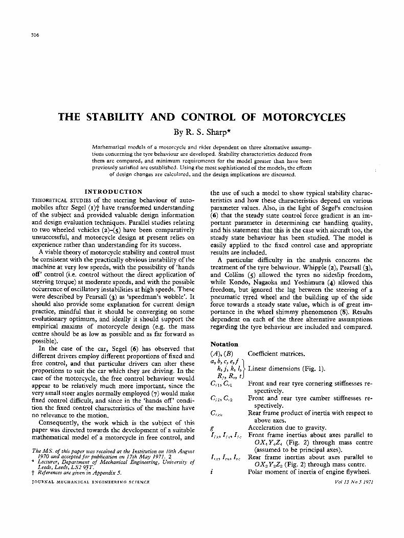
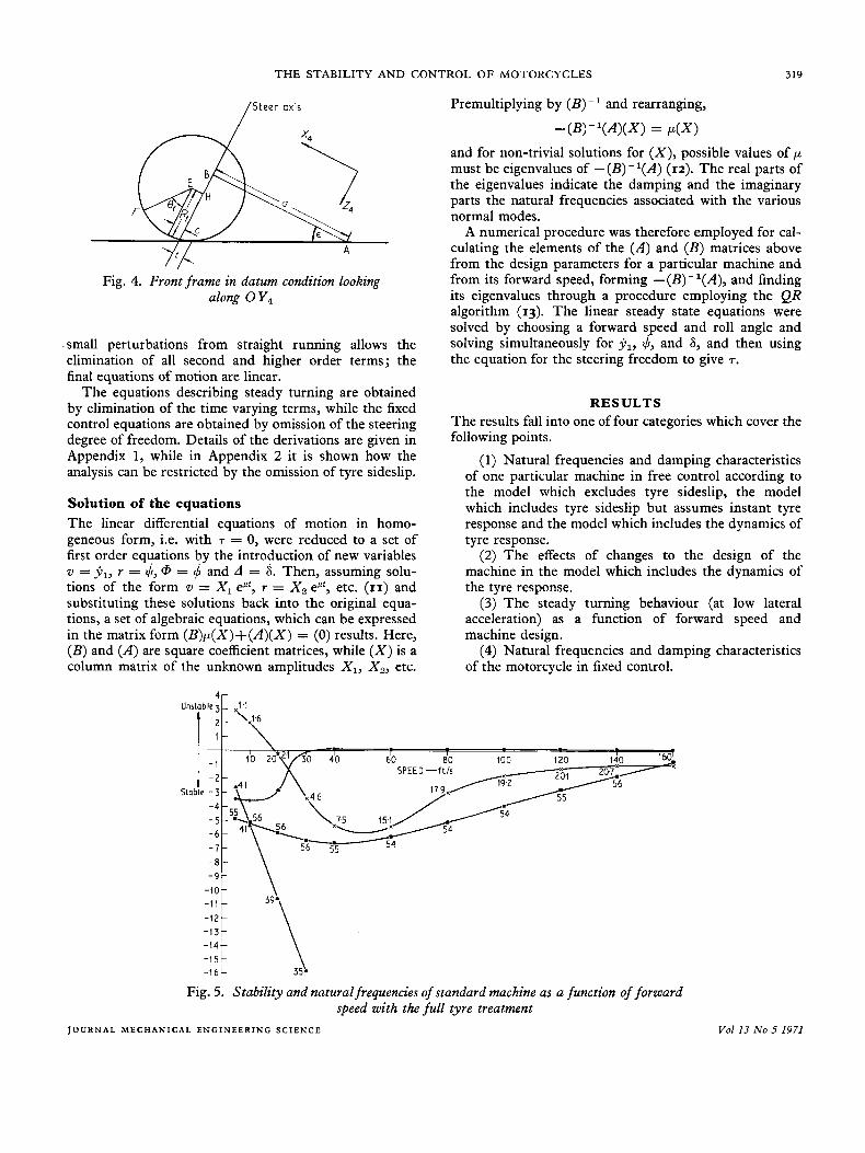
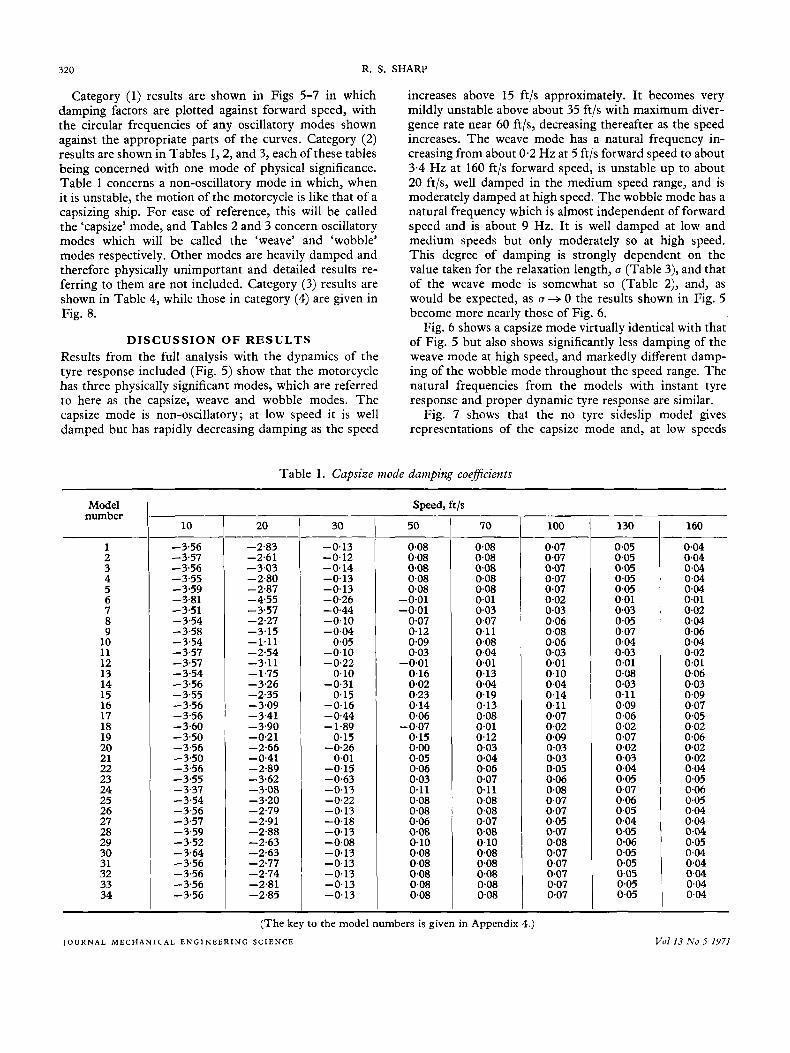
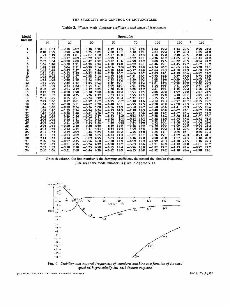
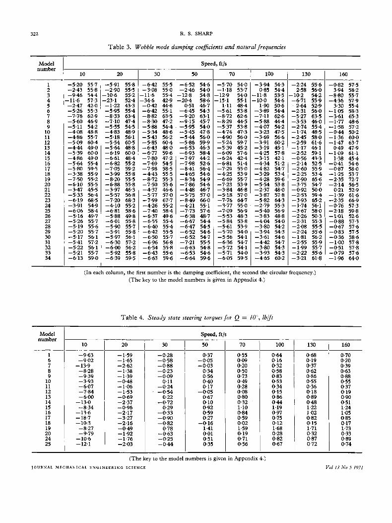
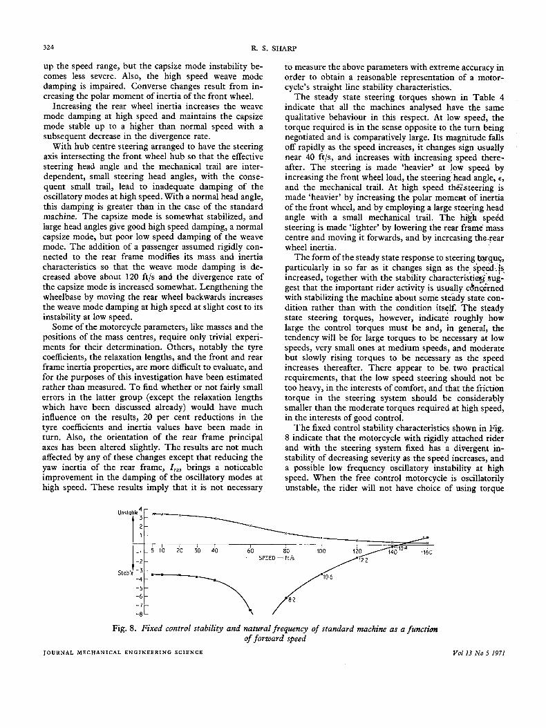
Category (1) results are shown in Figs 5-7 in which damping factors are plotted against forward speed, with the circular frequencies of any oscillatory modes shown against the appropriate parts of the curves. Category (2) results are shown in Tables 1,2, and 3, each of these tables being concerned with one mode of physical significance. Table 1 concerns a non-oscillatory mode in which, when it is unstable, the motion of the motorcycle is like that of a capsizing ship. For ease of reference, this will be called the 'capsize' mode, and Tables 2 and 3 concern oscillatory modes which will be called the 'weave' and 'wobble' modes respectively. Other modes are heavily damped and therefore physically unimportant and detailed results re- ferring to them are not included. Category ( 3 ) results are shown in Table 4, while those in category (4) are given in Fig. 8.
DISCUSSION OF RESULTS Results from the full analysis with the dynamics of the tyre response included (Fig. 5 ) show that the motorcycle has three physically significant modes, which are referred to here as the capsize, weave and wobble modes. The capsize mode is non-oscillatory; at low speed it is well damped but has rapidly decreasing damping as the speed
increases above 15 ft/s approximately. It becomes very mildly unstable above about 35 ft/s with maximum diver- gence rate near 60 ft/s, decreasing thereafter as the speed increases. The weave mode has a natural frequency in- creasing from about 0.2 Hz at 5 ft/s forward speed to about 3.4 Hz at 160 ftjs forward speed, is unstable up to about 20 ft/s, well damped in the medium speed range, and is moderately damped at high speed. The wobble mode has a natural frequency which is almost independent of forward speed and is about 9 Hz. I t is well damped at low and medium speeds but only moderately so at high speed. This degree of damping is strongly dependent on the value taken for the relaxation length, u (Table 3) , and that of the weave mode is somewhat so (Table 2), and, as would be expected, as u += 0 the results shown in Fig. 5 become more nearly those of Fig. 6 .
Fig. 6 shows a capsize mode virtually identical with that of Fig. 5 but also shows significantly less damping of the weave mode at high speed, and markedly different damp- ing of the wobble mode throughout the speed range. The natural frequencies from the models with instant tyre response and proper dynamic tyre response are similar.
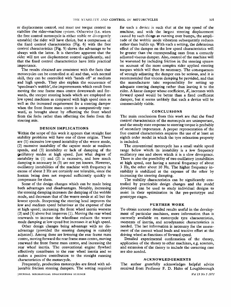
Fig. 7 shows that the no tyre sideslip model gives representations of the capsize mode and, at low speeds
Model number
1 2 3 4 5 6 7 8 9 10 11 12 13 14 15 16 17 18 19 20 21 22 23 24 25 26 27 28 29 30 31 32 33 34
Table 1. Capsize mode damping coefficients
Speed, ft/s
10 ~
-3.56 -3.57 -3.56 -3.55 -3.59 -3.81 -3.51 -3.54 -3.58 -3.54 -3.57 -3.57 -3.54 -3.56 -3.55 -3.56 -3.56 -3.60 -3.50 -3.56 -3.50 -3.56 -3.55 -3.37 -3.54 -3.56 -3.57 -3.59 -3.52 -3.64 -3.56 -3.56 -3.56 -3.56
20
-2.83 -2.61 -3.03 -2.80 -2.87 -4.55 -3.57 -2.27 -3.15 -1.11 -2.54 -3.11 -1.75 -3.26 -2.35 -3.09 -3.41 -3.90 -0.21 -2.66 -041 -2.89 -3.62 -3.08 -3.20 -2.79 -2.91 -2.88 -2.63 -2.63 -2.77 -2.74 -2.81 -2.85
30
-0.13 -0.12 -0.14 -0.13 -0.13 -0.26 -0.44 -0.10 -0.04 0.05
-0.10 -0.22 0.10
-0.31 0.15
-0.16 -0.44 -1.89 0.15
-0.26 0.01
-0.15 -0.63 -0.13 -0.22 -0.13 -0.18 -0.13 -0.08 -0.13 -0.13 -0.13 -0.13 -0.13
50
0.08 0.08 0.08 0.08 0.08
-0.01 -0.01 0.07 0.12 0.09 0.03
-0.01 0.16 0.02 0.23 0.14 0.06
-0.07 0.15 0.00 0.05 0.06 0.03 0.11 0.08 0.08 0.06 0.08 0.10 0.08 0.08 0.08 0.08 0.08
70
0.08 0.08 008 0.08 0.08 0.01 0.03 0.07 0.11 0.08 0.04 0.01 0.13 O W 0.19 0.13 0.08 0.01 0.12 0.03 0.04 0.06 0.07 0.11 0.08 0.08 0.07 008 0.10 0.08 0.08 0.08 0.08 0.08
100
0.07 0.07 0.07 0.07 0.07 0.02 0.03 0.06 0.08 0.06 0.03 0.01 0.10 0.04 0.14 0.11 0.07 0.02 0.09 0.03 0.03 0.05 0.06 0.08 0.07 0.07 0.05 007 0.08 0.07 0.07 0.07 0.07 0.07
130
0.05 0.05 0.05 0.05 0.05 0.01 0.03 0.05 0.07 0.04 0.03 0.01 0.08 0.03 0.11 0.09 0.06 0.02 0.07 0.02 0.03 0.04 0.05 0.07 0.06 0.05 0.04 0.05 0.06 0.05 0.05 0.05 0.05 0.05
160
0.04 0.04 0.04 0.04 0.04 0.01 0.02 0.04 0.06 0.04 0.02 0.01 0.06 0.03 0.09 0.07 0.05 0.02 0.06 0.02 0.02 0.04 0.05 0.06 0.05 0.04 0.04 0.04 0.05 0.04 0.04 0.04 0.04 0.04
-___
(The key to the model numbers is given in Appendix 4.)
J O U R N A L M E C H A N I C A L E N G I N E E R I N G S C I E N C E Vol13 No 5 1971
Model number
1 2 3 4 5 6 7 8 9 10 11 12 13 14 15 16 17 18 19 20 21 22 23 24 25 26 27 28 29 30 31 32 33 34
THE STABILITY AND CONTROL OF MOTORCYCLES
Table 2. Weave mode damping coefficients and natural frequencies
32 1
10
2.01 1.63 2.10 1.95 1.93 1.19 2.01 1.63 2.02 1.64 1.66 1.70 1.98 1-78 1.95 1.49 1.91 1.51 1.58 0.95 1.63 1.28 1.61 1.40 1.87 1.29 2.06 1.78 2.17 1.49 2.40 1.82 2.51 1.97 2.27 1.66 1.61 1.65 1.99 1.63 1.37 1-10 1-89 1.62 2-48 1.93 2.01 1.55 2.07 1.62 2.01 1.64 2.03 1-65 2.01 1.63 2.01 1.63 2.11 1.63 2.02 1-69 2.03 1.65 2.02 1.63 2.00 1.66
20
-0.18 2.09 -0.50 2.30 0-18 1.81
-0.17 2.09 -0.20 2.09 -0.50 1.71 0.04 2.11
-0.45 2.27 -0.12 1.75 -1.05 1.67 -0.50 1.70 -0.35 1.73 -0.63 1.82 -0.03 2.19 -0.20 1.98 0.18 2.35 0.35 2.51 0.72 2.01
-2.28 3.51 -0.19 2.34 -1.85 2.74 -0.28 1.99 0.49 2.36 0.16 1.81 0.11 2.05
-0.20 2.10 -0.12 2.14 -0.19 2.09 -0.23 2.09 -0.14 2.25 -0.27 2.15 -0.21 2.15 -0.18 2.10 -0.21 2.08
30
-3.36 4.56 -3.75 4.85 -2.87. 4.10 -3.29 4.57 -3.47 4.52 -6.39 2.34 -3.70 3.14 -3.51 544 -3.52 3.90 -2.98 5.16 -3.32 4'54 -3.54 4.02 -3.14 5.17 -3.49 4.05 -3.30 5.00 -3.36 4.39 -3.34 3.92 -1.92 1.67 -4.82 7.20 -3.16 5.00 -3.74 6.26 -3-51 4.39 -3.02 3.17 -2.91 342 -3.24 3.88 -3.36 4.60 -3.31 4.53 -344 4.65 -3.30 4.65 -3.09 4.95 -3.56 4.68 -3.34 4.72 -3.35 4.58 -344 4.50
Speed, ft/s
50
-6.59 11.4 -7.20 11.7 -5.77 10.8 -5.99 11.1 -8.32 11.6 -4.18 15.0 -10.6 7*3! -6.29 14.0 -7.59 10.2 -4.33 11.8 -5.73 11.2 -6.89 10.7 -5.09 12.1 -7.86 10.8 -6.26 12.2 -7.84 11.3 -9.15 10.4 -6.95 6.7f -6.48 16.1 -6.06 12.3 -4.93 14.3 -7.03 11.1 -8.33 8.6: -6.30 8Q -7.36 9.8f -6.59 11.5 -6.54 11.4 -5.42 12.2 -6.34 11.4 -5.83 11.4 -7.38 11.9 -6.20 11.7 -6.55 11.4 -6.82 11.3
70
-3.97 16.8 -4.40 17.1 -3.37 16.4 -4.29 16.1 -2.98 17.9 -2.22 16.1 -7.75 18.8 -3.17 18.9 -4.66 16.7 -2.21 16.2 -3.26 16.2 -3.96 16.2 -2.91 16.8 -4.66 16.9 -3.93 17.5 -4.95 17.5 -5.57 17.7 -540 14.6 -3.95 19.5 -3.50 17.7 -2.18 18.5 -4.21 16.9 -5.74 16.2 -5.82 15.2 -5.24 16.6 -3.88 17.0 -3.95 16.8 -2.75 15.8 -3.87 16.7 -4.16 17.0 -4.29 17.9 -3.63 16.6 -3.96 16.8 -4.13 16.8
100
-1.82 19.2 -2.23 19.2 -1.16 19.0 -2.36 18.9 -0.88 19.5 -1.46 17.1 -4.54 20.7 -1.64 21.3 -2.05 19.1 -0.33 18.9 -1.08 18.6 -1.57 18.4 -1.14 19.5 -2.27 19.1 -2.28 20.0 -2.79 19.8 -3.15 19.7 -2.12 17.3 -2.70 20.9 -1.68 20.6 -048 20.9 -1.88 19.2 -2.98 18.4 -2.48 18.5 -2.72 19.1 -1.76 19.3 -1.80 19.2 -1.25 17.7 -1.76 19.1 -2.00 20.0 -1.99 20.3 -1.71 18.9 -142 19.2 -1.92 19.2
- 130
-1-13 20.4 -1.49 20.3 -0.48 20.5 -1.65 20.3 -0-32 20.5 -1.45 17.7 -3.63 21.6 -1-50 22.3 -1.13 20.4 0-27 20.5
-0.29 20.0 -0.68 19.6 -0.71 20.9 -1-45 20.2 -1.99 21.0 -2.18 20.7 -2.40 20.6 -0.77 18.7 -2.28 21.3 -1.41 22.3 -0.07 22.1 -1.07 20.4 -2.00 19.4 -1.03 20.0 -1.90 20.3 -1.09 20.5 ~ .. ~. - -1.12 20.4 -0.85 18.7 -1.09 20.4 -1.27 21.3 -1.30 21.5 -1.12 20.0 -1.13 20.4 -1.18 20.4
(In each column, the first number is the damping coefficient, the second the circular frequency.) (The key to the model numbers is given in Appendix 4.)
Unstable
I I I 1 I T 60 80 100 f 20 140 160 - SPEED- ft/s
20 5 19 7
-9 -10 - 1 I
-13.- - 14
-16
Fig. 6. Stability and natural frequencies of standard machine as a function of forward speed with tyre sideslip but with instant response
160
-0.96 21.2 -1.25 21.0 -0.40 21.4 -1.44 21.2 -0-24 21.2 -1.67 18.2 -3.38 22.1 -1.69 22.7 -0.82 21.2 0.33 21.5
-0.05 20.9 -0.35 20.4 -0.77 21.7 -1.18 20.8 -2.07 21.5 -2.04 21.3 -2.15 21.1 -0.15 19.7 -2.07 21.5 -1.75 23.6 -0.07 22.8 -0.82 21.2 -1.61 20.1 -0.34 21.0 -1.66 21.0 -0.94 21.2 ~.~ ~~- -0.96 21.2 -0435 19.3 -0.93 21.1 -1.10 22.2 -1-16 22.3 -1.01 20.7 -0.97 21.2 -0.98 21.1
J O U R N A L M E C H A N I C A L E N G I N E E R I N G S C I E N C E Vol13 No 5 1971
322 R. S. SHARP
Table 3. Wobble mode damping coefficients and natural frequencies
Model number
Speed, ft/s
10 20 30 50 70 100 130 160
1 2 3 4 5 6 7 8 9 10 11 12 13 14 15 16 17 18 19 20 21 22 23 24 25 26 27 28 29 30 31 32 33 34
-5.20 55.7 -2.43 55.8 -9.46 54.4 -11.6 57.3 -2.47 42.0 -5.26 55.3 -7.76 62.9 -5.60 46.9 -5.11 54.2 -4.08 48.8 -4.86 55.7 -5.09 60.4 -4.44 49.0 -5.39 60.0 -4.86 49.0 -5.64 55.4 -5.80 59.5 -3.38 55.9 -7.50 55.2 -6.10 55.5 -3.47 45.5 -5.33 56.4 -6.19 68.5 -3.91 54.9 -6.06 58.4 -5.16 49.7 -5.26 55.7 -5.19 55.6 -5.20 55.7 -5.17 56.1 -5.41 57.2 -5.22 56.1 -5.21 55.7 -6.13 59.0
-5.91 55.8 -2.90 55.5 -10.6 55.2 -23.1 52.4 -1.22 43.3 -5.95 55.4 -8.33 63.4 -7.10 47.4 -5.55 54.5 -4.83 48.9 -5.18 56.1 -5.54 60.5 -5.64 48.8 -6.19 60.0 -6.61 48.4 -6.82 55.2 -7.05 59.2 -3.99 55% -8.20 55.5 -6.88 55.8 -3.97 46.3 -5.57 56.8 -7.20 68.3 -4.10 55.2 -6.81 58.6 -5.88 49.8 -6.01 55.8 -5.90 55.7 -5.91 554 -5.97 56.1 -6.30 57.2 -6.00 56.2 -5.92 55.8 -6.39 59.5
-6.42 55.5 -3.08 55.0 -11.6 55.4 -34.6 42.9 -0.42 44.6 -6.42 55.1 -8.82 63.5 -8.30 47.2 -5.88 54.4 -5.34 48.6 -5.43 56.2 -5.85 60.4 -6.43 48.0 -6.77 59.6 -7.80 47.2 -7.69 54.5 -7.98 58.5 -4.43 55.5 -8.72 55.3 -7.50 55.6 -4.37 46.6 -5.77 57.0 -7.99 67.7 -4.26 55.2 -7.40 58.4 -6.37 49.6 -6.55 55.4 -6.40 55.4 -6.42 55.5 -6.50 55.7 -6.96 56.8 -6.54 55.8 -6.43 55.6 -6.63 59.6
-6.52 54.6 -2.46 54.0 -12.8 54.8 -20.4 58.6 0.51 46.7
-6.45 54.3 -9.20 63.1 -9.15 45.7 -5.95 54.0 -5.45 47.8 -544 56.0 -5.86 59.9 -6.53 46.3 -6.93 58,4 -7.97 44.2 -7.98 52.6 -8.41 56.4 -4.65 54.6 -8.34 54.9 -7.86 54.6 -4.48 46.7 -5.75 57.0 -8.49 66.0 -4.21 55.1 -7.73 57.6
-6.67 54.4 -6.47 54.5 -6.52 54.6 -6.52 54.7 -7.21 55.5 -6.63 54.8 -6.53 54.6 -6.64 59.6
-6.38 48.7
-5.70 54.0 -1.18 53.7 -12.9 54.0 -15.1 55.1 1.11 48.4
-5.61 53.8 -8.72 62.6 -8.29 44.5 -5.37 53.8 -4.74 47.3 -4.90 56.0 -5.24 59.7 -5.39 45.2 -6.09 57.6 -6.24 42.4 -6.81 51.4 -7.29 55.0 -4.25 53.9 -6.69 55.7 -7.23 53.9 -3.84 46.8 -5.18 57.0 -7.76 64.7 -3.77 55.0 -7.09 56.9 -5.53 48.3 -5.84 53.8 -5.61 53.9 -5.70 54.0 -5.56 54.1 -6.36 54.7 -5.72 54.1 -5.71 54.0 -6.05 59.5
-3.94 54.3 0.85 54.4
-11.8 53.5 -10.0 54.6 1.90 50.6
-3.89 54.4 -7.11 62.6 -5.88 44.4 -4.07 54.2 -3.23 47.5 -3.69 56.6 -3.91 60.2 -3.19 45.1 -4.25 57.8 -3.15 42.1 -4.34 51.2 -4.82 54.7 -3.29 53.4
-2.24 55.6 2.58 56.0
-10.2 54.2 -6.71 55.9 2.64 52.9
-2.31 56.0 -5.27 63.5 -3.53 46.0 -2.74 55.4 -1.74 48.5 -2.45 58.0 -2.59 61.6 -1.17 46.1 -2.52 59.1 -0.56 43.3 -2.14 52.5 -2.60 55.9 -2.25 53.4 -2.90 65.6 -3.75 54.7 -0.92 50.0 -2.53 59.4 -3.93 65.2 -1.74 56.1 -3.67 58.0 -2.26 50.3 -2.31 55.3 -2.08 55.5 -2.24 55.6 -1.81 56.2 -2.55 55.9 -1.99 55.7 -2.22 55.6 -3.21 61.8
-0.82 57.5 3.94 58.2
-8.80 55.7 -4.36 57.9 3.30 55.4
-1.05 58.3 -3.61 65.3 -1.77 48.6 -1.58 57.2 -0.44 50.2 -1.36 60.0 -1.47 63.7 0.49 47.9
-1.09 61.1 1.38 45.4
-0.41 54.6 -0.87 58.0 -1.25 53.7
-4.28 59.6 -5.54 53.8 -2.37 48.0 -3.87 57.8
~~- _ _ . -2.35 72.7 -2.14 56.5 0.21 52.9
-1.39 61.6 -2.35 66.9 -5.82 64.3
-2.79 55.3 -540 56.9 -3.83 48.8 -4.04 54.0 -3.80 54.2 -3.94 54.3 -3.61 54.6 -4.42 54.7 -3.80 54.3 -3.93 54.3 -4.65 60.2
-0.76 57.3 -2.18 59.8 ~ ~- _. - -1.01 52.6 -0.88 57.3 -0.67 57.6 -0.83 57.5 -0.36 58.6 -1.00 57.8 -0.51 57.8 -0.79 57.6 -1.96 64.0
(In each column, the first number is the damping coefficient, the second the circular frequency.) (The key to the model numbers is given in Appendix 4.)
Table 4. Steady state steering torques for Q = l o ' , lblft
Model number
Speed, ft/s
10 20 30 I 50 70 100 130 160
1 6 7 8 9 10 11 12 13 14 15 16 17 18 19 20 24 25
-9.63 -9.02
-8.28 -9.39 -3.93 -6.07 -7.84 -6.00
-8.34
-13.9
- 13.0 - 13.6 - 18.7 - 10.3 -8.27 -9.79 - 10.6 - 12.1
-1.59 - 1.65 -2.62 - 1.38 - 1.39 -0.48 -1.06 - 1.53 - 0.69 -2.37 -0.96 -2.17 -3.27 -2.16 - 0.49 - 1.92 - 1.76 -2.03
-0.28 -0.58 -0.88 -0.23 -0.09 0.11
-0.24 -0.54 0.22
-0.72 0.29
-0.33 -0.90 -0.82 0.78
-0.63 -0.25 -0.44
0.37 -0.05 -0.03 0.34 0.56 0.40 0.17
-0.05 0.67 0.10 0.92 0.59 0.27
-0.16 1.41 0.01 0.51 0.35
0.55 009 0.20 0.50 0.73 0.49 0.28 0.08 0.80 0.32 1.10 0.84 0.59 0.02 1.59 0.19 0.71 0.56
0.64 0.16 0.32 0.58 0.83 0.53 0.34 0.15 0.86 0.44 1.19 0.97 0.75 0.12 1.68 0.28 0.82 0.67
0.68 0.19 0.37 0.62 0.86 0.55 0.36 0.18 0.89 0.48 1.22 1.02 0.82 0.15 1.71 0.32 0.87 0.72
0.70 0.20 0.39 0.63 0.88 0.55 0.37 0.19 0.90 0.51 1.24 1.05 0.85 0.17 1.73 0.33 0.89 0.74
(The key to the model numbers is given in Appendix 4.) J O U R N A L M E C H A N I C A L E N G I N E E R I N G S C I E N C E Vol I3 No 5 1971

THE STABILITY AND CONTROL OF MOTORCYCLES 323
Unstable 4
21 __ --
60 8’0 100 120 140 140 SPEED - f t / s
StableT3- -4 -5-
-
-1 ’t -1 6
Fig. 7 . Stability and natural frequencies of standard machine as a function of forward speed with tyre sideslip inhibited
only, of the weave mode, similar to those of the full model. With the no-sideslip model, however, the wobble mode is completely missing and no possibility for explanation of the ‘speedman’s wobble’ phenomenon is afforded.
The author is not aware of any information specifically concerning relaxation lengths for motorcycle tyres, and the figure of 0.8 ft which has been taken for the standard machine is based mainly on measurements by Labarre and Mills (14) on a 24 in section 124 in diameter tyre. If this figure is of the correct order of magnitude, which is very likely, it is apparent that a proper representation of the dynamic characteristics of the motorcycle depends on the inclusion oftyre sideslip and of the tyre relaxation property.
The parameter effects recorded in Tables 1, 2 and 3 show that the capsize mode is comparatively little altered, but the weave and wobble modes can be influenced con- siderably by parameter changes. The last is most sensitive to the steer damping coefficient, K, increasing which stabilizes the wobble at the expense of the weave mode, although changes to the latter with varying K are not great. By increasing the steering damping in fact, adequate damping of the wobble mode at any speed (up to the 160 ft/s maximum employed in this study) can be obtained, so that the potential problem at high speed is inadequate damping of the weave mode. The relaxation length is also an important parameter as already indicated, and in- creasing it destabilizes both the weave and wobble modes appreciably.
Lowering the mass centre of the rear frame has virtually no effect on the wobble mode, but increases the damping of the weave mode at low and high speeds while decreasing it at medium speeds. Since the damping of this mode is normally more than adequate at medium speeds, these changes will be advantageous in practice. Further advan- tage is obtained from the stabilization of the capsize mode throughout the speed range. Moving the rear frame mass J O U R N A L M E C H A N I C A L E N G I N E E R I N G S C I E N C E
2
centre forwards necessitates an increase in steer damping to maintain the stability of the wobble mode and, if this increase is provided, substantial improvements to the weave mode in the form of increased damping, parti- cularly at high speeds, result. Also, slightly increased damping of the capsize mode is obtained.
If the front frame mass centre is moved rearward, more steer damping is required to stabilize the wobble mode and, with this provided, increased damping of the weave mode at high speed is obtained. Moving the front frame mass centre up or down by practicable amounts causes changes which can alternatively be achieved by respectively in- creasing or decreasing the steer damping slightly.
Changes to the mechanical trail, t , and the steering head angle, e, show that if the steering head is steepened, the weave mode damping at high speed is reduced while at low speed it is increased. With normal and greater than normal trail, the instability of the capsize mode at medium and high speeds is reduced in severity, and from the view- point of straight line stability, the steep steering head appears advantageous for low speed machines (i.e. those with top speeds less than about 100 ft/s). As the top speed increases, the steering head angle must be increased to achieve adequate damping of the weave mode, the steering damper being tailored to damp the wobble mode sufficiently. However, with a shallow steering head, high trail must be employed or the instability of the capsize mode at medium and high speeds will be too severe. With the normal steering head angle, too little trail causes an instability of the capsize mode somewhat more severe than normal and a slight lack of damping of the weave mode at high speed. Employing more trail than normal has very little effect.
If the gyroscopic effects of the front wheel are reduced, less steering damping is necessary to damp the wobble mode at high speed adequately. With this reduced steer damping, stabilization of the weave mode occurs higher
Vol13 No 5 1971
324 R. S. SHARP
up the speed range, but the capsize mode instability be- comes less severe. Also, the high speed weave mode damping is impaired. Converse changes result from in- creasing the polar moment of inertia of the front wheel.
Increasing the rear wheel inertia increases the weave mode damping at high speed and maintains the capsize mode stable up to a higher than normal speed with a subsequent decrease in the divergence rate.
With hub centre steering arranged to have the steering axis intersecting the front wheel hub so that the effective steering head angle and the mechanical trail are inter- dependent, small steering head angles, with the conse- quent small trail, lead to inadequate damping of the oscillatory modes at high speed. With a normal head angle, this damping is greater than in the case of the standard machine. The capsize mode is somewhat stabilized, and large head angles give good high speed damping, a normal capsize mode, but poor low speed damping of the weave mode. The addition of a passenger assumed rigidly con- nected to the rear frame modifies its mass and inertia characteristics so that the weave mode damping is de- creased above about 120 ft/s and the divergence rate of the capsize mode is increased somewhat. Lengthening the wheelbase by moving the rear wheel backwards increases the weave mode damping at high speed at slight cost to its instability at low speed.
Some of the motorcycle parameters, like masses and the positions of the mass centres, require only trivial experi- ments for their determination. Others, notably the tyre coefficients, the relaxation lengths, and the front and rear frame inertia properties, are more difficult to evaluate, and for the purposes of this investigation have been estimated rather than measured. To find whether or not fairly small errors in the latter group (except the relaxation lengths which have been discussed already) would have much influence on the results, 20 per cent reductions in the tyre coefficients and inertia values have been made in turn. Also, the orientation of the rear frame principal axes has been altered slightly. The results are not much affected by any of these changes except that reducing the yaw inertia of the rear frame, I,,, brings a noticeable improvement in the damping of the oscillatory modes at high speed. These results imply that it is not necessary
to measure the above parameters with extreme accuracy in order to obtain a reasonable representation of a motor- cycle’s straight line stability characteristics.
The steady state steering torques shown in Table 4 indicate that all the machines analysed have the same qualitative behaviour in this respect. At low speed, the torque required is in the sense opposite to the turn being negotiated and is comparatively large. Its magnitude falls off rapidly as the speed increases, it changes sign usually near 40 ft/s, and increases with increasing speed there- after. The steering is made ‘heavier’ at low speed by increasing the front wheel load, the steering head angle, E ,
and the mechanical trail. At high speed the‘hteering is made ‘heavier’ by increasing the polar moment of inertia of the front wheel, and by employing a large stwring head angle with a small mechanical trail. The hi’& speCd steering is made ‘lighter’ by lowering the rear frame mass centre and moving it forwards, and by increasing the-rear wheel inertia.
The form of the steady state response to steering twgue, particularly in so far as it changes sign as the. s‘peed.ts. increased, together with the stability characteristic$.sug- gest that the important rider activity is usually c&n&rned with stabilizing the machine about some steady state con- dition rather than with the condition itself. The steady state steering torques, however, indicate roughly how large the control torques must be and, in general, the tendency will be for large torques to be necessary at low speeds, very small ones at medium speeds, and moderate but slowly rising torques to be necessary as the speed increases thereafter. There appear to be, two practical requirements, that the low speed steering should not be too heavy, in the interests of comfort, and that the friction torque in the steering system should be considerably smaller than the moderate torques required at high speed, in the interests of good control.
The fixed control stability characteristics shown in Fig. 8 indicate that the motorcycle with rigidly attached rider and with the steering system fixed has a divergent in- stability of decreasing severity as the speed increases, and a possible low frequency oscillatory instability at high speed. When the free control motorcycle is oscillatorily unstable, the rider will not have choice of using torque
I:;,, 5 10 20 30 40 60 80 100 1 2 f l P 4 160 P r 7 7 SPEED - f t / s
Fig. 8. Fixed control stability and natural frequency of standard machine as a function of forward speed
J O U R N A L M E C H A N I C A L E N G I N E E R I N G S C I E N C E Vol 13 No 5 1971
T H E S~fr\BILI'I'Y XSL> CONTROL 01: MO1'OKCYCLES 325
or displacement control, and must use torque control to stabilize the rider-machine system. Otherwise (i.e. when the free control motorcycle is either stable or divergently unstable) the rider will have choice, but a comparison of the fixed control characteristics (Fig. 6 ) with the free control characteristics (Fig. 5) shows the advantage to be always with the latter. It is therefore apparent that the rider will not use displacement control significantly, and that the fixed control characteristics have little practical importance.
The results obtained are consistent with the facts that motorcycles can be controlled at all and that, with normal skill, they can be controlled with 'hands off' at medium and high speeds. They also explain the occurrence of 'speedman's wobble', the improvements which result from moving the rear frame mass centre downwards and for- wards, the steeper steering heads which are employed on low speed machines as compared with high speed ones as well as the increased requirement for a steering damper when the front frame mass centre is comparatively rear- ward, as brought about by offsetting the front wheel from thi forks rather than offsetting the forks from the steering axis.
DESIGN IMPLICATIONS Within the scope of this work it appears that straight line stability problems will have one of three origins. These are (1) excessive low speed instability of the weave mode, (2) excessive instability of the capsize mode at medium speeds, and (3) instability or lack of damping of the gscillatory modes at high speed. Just what degree of instability in (1) and (2) is excessive, and how much damping is necessary in ( 3 ) are not yet known. However, oscillatory instabilities of the machine with frequency in excess of about 2 Hz are certainly not tolerable, since the human being does not respond sufficiently quickly to compensate for them.
Some of the design changes which can be made bring both advantages and disadvantages. Notably, increasing the steering damping increases the damping of the wobble mode, and decreases that of the weave mode at all but the lowest speeds. Steepening the steering head improves the low and medium speed behaviour at the expense of that at high speed; increasing the front wheel inertia worsens (2) and ( 3 ) above but improves (1). Moving the rear wheel rearwards to increase the wheelbase reduces the weave mode damping at low speed but increases it at high speed.
Other design changes bring advantage with no dis- advantage (provided the steering damping is suitably adjusted). Among these are lowering the rear frame mass centre, moving forward the rear frame mass centre, moving rearward the front frame mass centre, and increasing the rear wheel inertia. The conventional engine flywheel effectively contributes to the rear wheel inertia and so makes a positive contribution to the straight running characteristics of the motorcycle.
Frequently, production motorcycles are fitted with ad- justable friction steering dampers. The setting required J O U R N A L M E C H A N I C A L E N G I N E E R I N G S C I E N C E
for such a devicc is such that at the top speed of the machine, and with the largest steering displacement caused by such things as running over bumps, the ampli- tude of the wobble mode vibration subsequently reduces rather than builds up. With such a setting, the deleterious effect of the damper on the low speed characteristics will be greater than the corresponding ones from a correctly adjusted viscous damper. Also, control of the machine will be worsened by including friction in the steering system on account of the more complex rider applied steering torques which will then be necessary. The consequences of wrongly adjusting the damper can be serious, and it is recommended that viscous damping be provided, and that the manufacturer take responsibility for setting up adequate steering damping rather than leaving it to the rider. A linear damper whose coefficient, K, increases with forward speed would be better than a fixed coefficient damper, but it seems unlikely that such a device will be commerciably viable.
CONCLUSIONS The main conclusions from this work are that the fixed control characteristics of the motorcycle are unimportant, and the steady state response to steering torque is probably of secondary importance. A proper representation of the free control characteristics requires the use of at least an eighth order model in which the tyre relaxation property is included.
The conventional motorcycle has a small stable speed range below which its instability is a low frequency oscillatory one and above which it is a slow divergence. There is also the possibility of two oscillatory instabilities at high speed, one having a natural frequency of about 3 Hz, the other about 10 Hz. The higher frequency in- stability is stabilized at the expense of the other by increasing the steering damping.
The stability characteristics can be significantly con- trolled by practicable design changes and the model developed can be used to study individual designs to assist in their optimization in the pre-prototype and prototype stages.
FURTHER WORK T o obtain accurate detailed results useful in the develop- ment of particular machines, more information than is currently available on motorcycle tyre characteristics, moments of inertia, and aerodynamic characteristics is needed. The last information is necessary for the assess- ment of the correct wheel loads and tractive effort at the driving wheel as functions of forward speed.
Detailed experimental confirmation of the theory, application of the theory to other machines, e.g. scooters, and extension of the theory to include the cornering case are also needed.
ACKNOWLEDGEMENTS The author gratefully acknowledges helpful advice received from Professor F. D. Hales of Loughborough
Vo113 No 5 1971
326 R. S. SHARP
University of Technology. Part of the work was carried out while the author was employed in the Motorcycle Division of the Birmingham Small Arms Company Limited.
APPENDIX 1
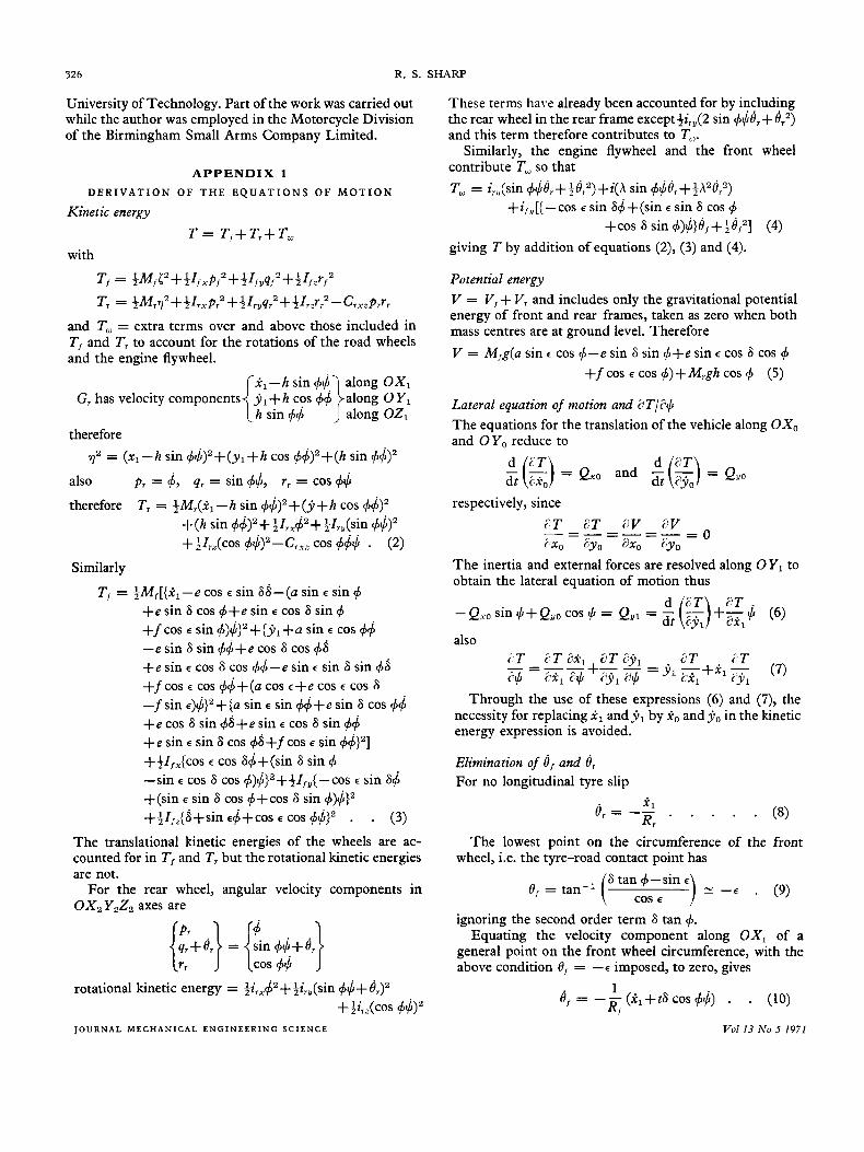
D E R I V A T I O N O F T H E E Q U A T I O N S O F MOTION
Kinetic energy
T = Tf+T,+Tw with
T, = +Mf t2 ++If ,pf2 ++Zfyqf2 + +Ifzrf Tr = +Mr7'++Irxp,2 +;Zryq,2 + +Ir,-r,2 -CrxaPrrr
and T, = extra terms over and above those included in T, and T, to account for the rotations of the road wheels and the engine flywheel.
1, - h sin 44 along OX, G, has velocity components j , + h cos $4 along O Y ,
( h sin 44 ')along OZ, therefore
72 = ( x l - h sin +$)Z+(yl+h cos +4)z+(h sin #J$)~
also pr = 4, qr = sin &, rr = cos +$ therefore T, = +Mr(il - h sin 4$)z + ( j +h cos +$)2
+ ( h sin &>z++Zrx$2++~ry(sin 44)' ++Zr,(c0s ~$>"Cr,, cos +$$ . (2)
Similarly
T, = +M,[{k,-e cos E sin 66-(a sin E sin 4 +e sin 6 cos 4+e sin 6 cos 6 sin q5 +f cos E sin +)$}z + { j , +a sin E cos 44 -e sin 6 sin +j+e cos 6 cos 4s +e sin E cos 6 cos 44-e sin E sin 6 sin 46 +fcos -E cos &$+(a cos -E+e cos -E cos 6 -f sin -E)$>z+{a sin -E sin +$+e sin 6 cos 44 +e cos 6 sin @+e sin -E cos 6 sin $4 +e sin -E sin 6 cos @+f cos -E sin 44>z] ++I, ,{cos E cos 64 + (sin 6 sin 4 -sin E cos 6 cos ~)$)z++4~,y{-cos E sin 66 +(sin E sin 6 cos ++cos 6 sin 4)$}z ++Ifr-{S+sin E$+COS E cos +$>z . . (3)
The translational kinetic energies of the wheels are ac- counted for in T, and T, but the rotational kinetic energies are not.
For the rear wheel, angular velocity components in OX,YzZz axes are
{?el} = l n 4 $ + e r } cos 44
rotational kinetic energy = +ir,p++ir,(sin +$+ Br)2 ++i,,(cos +$Iz
J O U R N A L M E C H A N I C A L E N G I N E E R I N G S C I E N C E
These terms have already been accounted for by including the rear wheel in the rear frame except+irY(2 sin +@,+ eTz) and this term therefore contributes to To.
Similarly, the engine flywheel and the front wheel contribute T, so that To, = i,,(sin #$dr+@,2>+i(h sin 4$er++Azerz)
+i,,[{-cos -E sin 6$+(sin E sin 6 cos 4 +cos 6 sin 4)$>8, ++efz] (4)
giving T by addition of equations (2), (3) and (4).
Potential energy V = V, + Vr and includes only the gravitational potential energy of front and rear frames, taken as zero when both mass centres are at ground level. Therefore V = M,g(a sin E cos 4-e sin 6 sin 4+e sin E cos 6 cos 4
+ f cos E cos 4) + M,gh cos 4 (5)
Lateral equation of motion and aT/@ The equations for the translation of the vehicle along OXo and OYo reduce to
d 2T d dt i x o = Qxo and d t -(-) ?jo = QVo
respectively, since PT 2T d V EV ---=-=-- - - 0 i x o ;yo ax, ay0
The inertia and external forces are resolved along 0 Y1 to obtain the lateral equation of motion thus
d i3T P T . - Qho sin #+ Qyo cos 4 = Qyl = - (-) +z $ (6)
dt CYl also
Through the use of these expressions (6) and (7), the necessity for replacing il and j1 by io and yo in the kinetic energy expression is avoided.
Elimination of 4, and 6, For no longitudinal tyre slip
The lowest point on the circumference of the front wheel, i.e. the tyre-road contact point has
6 tan 4 -sin E ) 2 --E . (9) ( C O S E 8, = tan-'
ignoring the second order term 6 tan 4. Equating the velocity component along O X , of a
general point on the front wheel circumference, with the above condition 8, = --E imposed, to zero, gives
Vol 13 No 5 1971
THE STABILITY AND CONTROL OF MOTORCYCLES 327
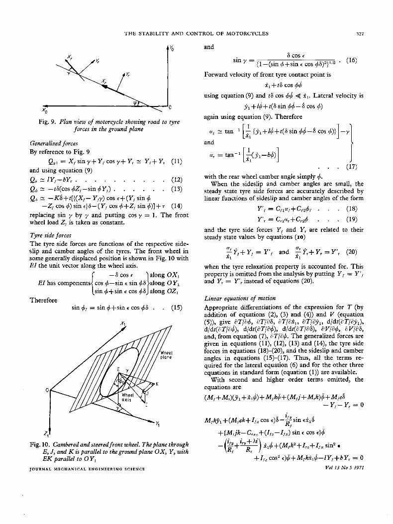
Fig. 9. Plan view of motorcycle showing road to tyre forces in the ground plane
Generalized forces By reference to Fig. 9
and using equation (9) QUl = X , sin y+ Y , cos y+ Y, N Y,+ Y , (11)
Q, N IYf-bY, . . . . . . . . . - (12) Q, 21 -tS(cos +Z,-sin +Y,) . . . . . * (13) Q6 N -KS+t [ { (X , - Y,y) cos E + ( Y , sin + replacing sin y by y and putting cos y = 1. The front wheel load Z, is taken as constant.
Tyre side forces The tyre side forces are functions of the respective side- slip and camber angles of the tyres. The front wheel in some generally displaced position is shown in Fig. 10 with EI the unit vector along the wheel axis.
-Z,cos+)sinc}S-(Y,cos++Z,sin+)]+T (14)
EI has components
Therefore sin +, = sin ++sin E cos +S . . (15)
X
0
=1 t Fig. 10. Cambered and steered front wheel. The plane through
E, J, and K is parallel to the ground plane O X , Y , with E K parallel to 0 Y ,
J Q U R N A L M E C H A N l C A L E N G I N E E R I N G SCIENCE
and 6 cos E
sin y = (16) { 1 -(sin + +sin c cos +8)2}112 . Forward velocity of front tyre contact point is
&+ti3 cos +$ using equation (9) and t6 cos +$ < .tl. Lateral velocity is
y,+I$+t(S sin 4d-S cos +)
again using equation (9). Therefore
and
a, = tan-' - (Y,-b$) Ll . I . . . (17)
with the rear wheel camber angle simply 4. When the sideslip and camber angles are small, the
steady state tyre side forces are accurately described by linear functions of sideslip and camber angles of the form
and the tyre side forces Y, and Y , are related to their steady state values by equations (10)
U Or 2 Y,+ Y, = Y' , and - Yr+ Y, = Y', (20) 111 21
when the tyre relaxation property is accounted for. This property is omitted from the analysis by putting Y , = Y ' , and Y, = Y , instead of equations (20).
Linear equations of motion Appropriate differentiations of the expression for T (by addition of equations (2), (3) and (4)) and V (equation (5)), give aT/a+, aT/aS, aT/ax,, aT/ay,, d/dt(aT/3yi,), d/dt(aT/a$), d/dt(aT/a&, d/dt(aT/a8), a V/a+, 6V/aS, and, from equation (7), aT/a#. The generalized forces are given in equations (l l) , (12), (13) and (14), the tyre side forces in equations (18)-(20), and the sideslip and camber angles in equations (15)-(17). Thus, all the terms re- quired for the lateral equation (6) and for the other three equations in standard form (equation (1)) are available.
With second and higher order terms omitted, the equations are
(M,+ Mr)(jl +a,$) + M,k$+(M,j+Mrh)d;+ M,e8 - Y,- Y , = 0
M,kj ,+(M,ek+I, , cos c)S-2'"sin R,
+ (M,jk - C,,, + (I,, - I,,.) sin E cos ~ } d ; -($+?) i , ~ + ( M , k 2 + I , , + I , , sin2
+Ifz COS' E)$+M,k~,$- lY ,+bY, = 0 Vol 13 No 5 1971
328 R. S. SHARP
APPENDIX 2
E Q U A T I O N S O F M O T I O N W I T H T Y R E S I D E S L I P E L I M I N A T E D
The condition that the tyres do not sideslip implies that uf = CI, = 0. Thus, from equations (16) and (17)
1 X1 7 ( ~ , + z * - t S ) - 6 cos E = 0
and j , = b$, giving . x, cos E 8 + t S
and j , = (kZ) (a, cos E S + t S ) '= b+Z and hence
2, cos E 8 + t 8 $ = and y, = (kZ) (x, cos &+tS) b+Z
for 1, constant.
motion and eliminating Yf and Y,, we obtain [ ( M , j + M,h)bt + M,ejZl + I,, sin dl
+{~,jk-c,,,+(Z,~-Z,,) sin E cos e}t]E;
+[(M,j+M,h)b cos ci,+h k, cos E Z ,
+{M,j~-C,~~+(Z,~-Z,,) sin E cos e}il cos E
Substituting these expressions in the linear equations of
R f
+(M,j2+M,h2+Z, ,+Z~, COS' e+Z,, sin2 c)Zli
-(M,j+M,h)gl,fj = o J O U R N A L M E C H A N I C A L E N G I N E E R I N G S C I E N C E
and [I,Jl' +M,e2Zl2+tZ{(M,+Mr)b2 +2Mfbk+Mfk2 + I,,
+ KZ,' + t{(M, + M,)b'il cos E
+2M,bki1 cos E+(M,+M,)bti,-l1' Z 1 i l sin c
+(M,k2+Z,,+Z,, sin2 R,
cos2 c ) i 1 cos E
ZftZ12 sin c-M,eZ12g sin E
i 1 2 Z 1 cos E+t{(M,+M,)i12b cos E
+ M , k i 1 2 cos E } S+[M,ejZl2++l,,Zl2 sin E I + bli t(M,j + M,h) + tzi{ M,jk-C,,,
+(IjZ-I,,)sin E cos E } ] J +
- t t i -+- "'R',")] Z1ilQ+(Z,t-Mfeg)Z,2~ = 0
where I , = b+Z and is the wheelbase, and no steering torque is applied.
These equations were used to give the results in Fig. 7.
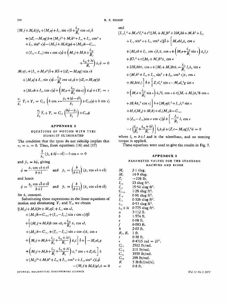
APPENDIX 3 PARAMETER VALUES FOR T H E S T A N D A R D
M A C H I N E A N D RIDER
M , 2.1 slug. M , 14.9 slug.
I,, 23 slug ft2. I,, 1554 slug ft'. C,,y, 1.28 slug ft'. Z I x 0.91 slug ft2. I,, 0.326 slug ft'.
Y 053 slug ft2. ',,,+hi 0.775 slug ft'. a 3.1 12 ft. b 1.574 ft. e 0.08 ft.
0.093 ft. 2.02 ft. h
R,, R, 1 ft. t 0.38 ft. E 0.4715 rad = 27". C,, 2512 lb/rad. C,, 211 lb/rad. C,, 3559 lb/rad. C,, 298 Ib/rad. K 5 lb ft/(rad/s). I 3 0.8 ft.
z, -226 lb.
f
Vol 13 No 5 1971
T H E STABILITY AND CONTROL OF MOTORCYCLES 329
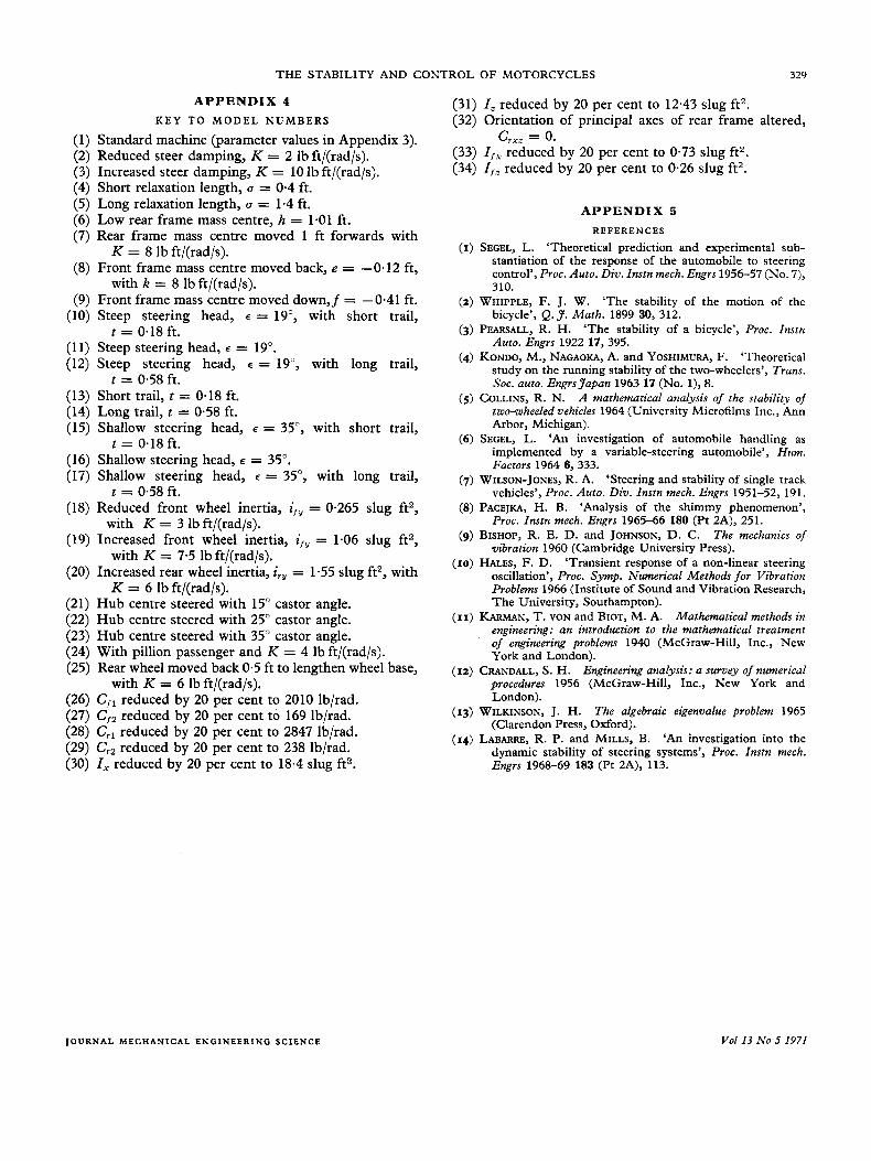
APPENDIX 4 KEY T O M O D E L NUMBERS
(1) Standard machine (parameter values in Appendix 3). (2) Reduced steer damping, K = 2 lb ft/(rad/s). (3) Increased steer damping, K = 10 lb ft/(rad/s). (4) Short relaxation length, u = 0.4 ft. (5) Long relaxation length, u = 1.4 ft. (6) Low rear frame mass centre, h = 1.01 ft. (7) Rear frame mass centre moved 1 ft forwards with
(8) Front frame mass centre moved back, e = -0.12 ft,
(9) Front frame mass centre moved down,f = -0-41 ft. (10) Steep steering head, E = 19", with short trail,
(11) Steep steering head, E = 19". (12) Steep steering head, E = 19", with long trail,
(13) Short trail, t = 0.18 ft. (14) Long trail, c = 0.58 ft. (15) Shallow steering head, E = 35", with short trail,
(16) Shallow steering head, E = 35". (17) Shallow steering head, E = 35", with long trail,
(18) Reduced front wheel inertia, i,y = 0.265 slug ft2,
(19) Increased front wheel inertia, i,, = 1.06 slug ft2,
(20) Increased rear wheel inertia, ir, = 1.55 slug ft2, with
(21) Hub centre steered with 15" castor angle. (22) Hub centre steered with 25" castor angle. (23) Hub centre steered with 35" castor angle. (24) With pillion passenger and K = 4 lb ft/(rad/s). (25) Rear wheel moved back 0.5 ft to lengthen wheel base,
(26) C,, reduced by 20 per cent to 2010 lb/rad. (27) C,, reduced by 20 per cent to 169 lb/rad. (28) C,, reduced by 20 per cent to 2847 lb/rad. (29) C,, reduced by 20 per cent to 238 lb/rad. (30) I, reduced by 20 per cent to 18.4 slug ft2.
K = 8 lb ft/(rad/s).
with k = 8 lb ft/(rad/s).
t = 0.18 ft.
t = 0.58 ft.
t = 0.18 ft.
t = 0.58 ft.
with K = 3 lb ft/(rad/s).
with K = 7.5 lb ft/(rad/s).
K = 6 lb ft/(rad/s).
with K = 6 lb ft/(rad/s).
(31) Z, reduced by 20 per cent to 12.43 slug ft2. (32) Orientation of principal axes of rear frame altered,
(33) I,, reduced by 20 per cent to 0.73 slug ft2. (34) Z,- reduced by 20 per cent to 0.26 slug ft2.
c,,, = 0.
APPENDIX 5 R E F E R E N C E S
(I) SEGEL, L. 'Theoretical prediction and experimental sub- stantiation of the response of the automobile to steering control', Proc. Auto. Div. Znstn mech. Engrs 1956-57 (No. 7), 310.
'The stability of the motion of the bicycle', Q. 3. Math. 1899 30, 312.
'The stability of a bicycle', Proc. Znstn Auto. Engrs 1922 17, 395.
'Theoretical study on the running stability of the two-wheelers', Trans. SOC. auto. EngrsJapan 1963 17 (No. l), 8.
A mathematical analysis of the stability of two-wheeled vehicles 1964 (University Microfilms Inc., Ann Arbor, Michigan).
(6) SEGEL, L. 'An investigation of automobile handling as implemented by a variable-steering automobile', Hum. Factors 1964 6, 333.
(7) WILSON-JONES, R. A. 'Steering and stability of single track vehicles', Proc. Auto. Div. Znstn mech. Engrs 1951-52, 191.
(8) PACEJKA, H. B. 'Analysis of the shimmy phenomenon', Proc. Znstn mech. Engrs 1965-66 180 (Pt 2A), 251.
(9) BISHOP, R. E. D. and JOHNSON, D. C. The mechanics of vibration 1960 (Cambridge University Press).
'Transient response of a non-linear steering oscillation', Proc. Symp. Numerical Methods for Vibration Problems 1966 (Institute of Sound and Vibration Research, The University, Southampton).
(11) KARMAN, T. VON and BIOT, M. A. Mathematical methods in engineering: an introduction to the mathematical treatment of engineering problems 1940 (McGraw-Hill, Inc., New York and London).
Engineering analysis: a survey of numerical procedures 1956 (McGraw-Hill, Inc., New York and London).
(13) WILKINSON, J. H. The algebraic eigenvalue problem 1965 (Clarendon Press, Oxford).
(14) LABARRE, R. P. and MILLS, B. 'An investigation into the dynamic stability of steering systems', Proc. Instn mech. Engrs 1968-69 183 (Pt 2A), 113.
(2) WHIPPLE, F. J. W.
(3) PEARSALL, R. H.
(4) KONDO, M., NAGAOKA, A. and YOSHIMURA, F.
(5) COLLINS, R. N.
(10) HALES, F. D.
(12) CRANDALL, S. H.
J O U R N A L MECHANICAL E N G I N E E R I N G S C I E N C E Vol13 No 5 1971