Embed Size (px)
Citation preview
This article was downloaded by: [The University of Manchester Library]On: 30 October 2014, At: 03:17Publisher: Taylor & FrancisInforma Ltd Registered in England and Wales Registered Number: 1072954 Registered office: Mortimer House,37-41 Mortimer Street, London W1T 3JH, UK
Journal of Modern OpticsPublication details, including instructions for authors and subscription information:http://www.tandfonline.com/loi/tmop20
The step azimuthal optical fiberI.M. Fabbri a & A. Lucianetti ba Centro di Ricerca di Fisica Matematica , Sesto San Giovanni 20099, Italyb Physics Department , University of Florida , Gainesville, FL 832611, USAPublished online: 20 Apr 2010.
To cite this article: I.M. Fabbri & A. Lucianetti (2010) The step azimuthal optical fiber, Journal of Modern Optics, 57:7,528-535, DOI: 10.1080/09500341003675323
To link to this article: http://dx.doi.org/10.1080/09500341003675323
PLEASE SCROLL DOWN FOR ARTICLE
Taylor & Francis makes every effort to ensure the accuracy of all the information (the “Content”) containedin the publications on our platform. However, Taylor & Francis, our agents, and our licensors make norepresentations or warranties whatsoever as to the accuracy, completeness, or suitability for any purpose of theContent. Any opinions and views expressed in this publication are the opinions and views of the authors, andare not the views of or endorsed by Taylor & Francis. The accuracy of the Content should not be relied upon andshould be independently verified with primary sources of information. Taylor and Francis shall not be liable forany losses, actions, claims, proceedings, demands, costs, expenses, damages, and other liabilities whatsoeveror howsoever caused arising directly or indirectly in connection with, in relation to or arising out of the use ofthe Content.
This article may be used for research, teaching, and private study purposes. Any substantial or systematicreproduction, redistribution, reselling, loan, sub-licensing, systematic supply, or distribution in anyform to anyone is expressly forbidden. Terms & Conditions of access and use can be found at http://www.tandfonline.com/page/terms-and-conditions
Journal of Modern OpticsVol. 57, No. 7, 10 April 2010, 528–535
The step azimuthal optical fiber
I.M. Fabbria and A. Lucianettib*y
aCentro di Ricerca di Fisica Matematica, Sesto San Giovanni 20099, Italy;bPhysics Department, University of Florida, Gainesville FL 832611, USA
(Received 18 November 2009; final version received 1 February 2010)
We present a new kind of optical fiber by introducing a perturbation of the classical core–cladding fiber design.The azimuthal symmetry of the refractive index is modified by a narrow parabolic perturbation. The perturbationacts like an azimuthal potential well against the propagating pulse. Theoretical calculations lead to a strongselection of the azimuthal modes. We show that by conveniently choosing the parameters, the fundamental modeis not reflected as a result of its radial field distribution.
Keywords: optical fibers; propagation optics; fiber laser; beam propagation; specialty fiber; transmission controls
1. Introduction
Mode selectivity is one of the most important issues inthe study of propagation of pulses in optical fibers. Oneapproach to obtain highmode selectivity is to externallycoil the wire or to use the bend-loss suppression ofhigher order modes [1–3] and the selection tapers [4].These methods have some drawbacks such as Ramanscattering and Brillouin scattering, which limit theavailable output powers of fiber lasers [5]. Using bendloss to select high-order modes allows the core diameterto be increased well beyond the single mode limit.Unfortunately, coiling the optical fiber leads tounwanted high losses and limits the achievable peakpower. Another approach is to break the azimuthalconstant distribution of the inner refractive index, as inthe case of chirally coupled, D-shaped, rectangular core,or PANDA fibers [6].
Recently, a new design based on spiral indexdistribution has been proposed. In this kind of fiber,starting from the transverse electric field of a particularpropagating mode, two eigenvalue equations werefound [7], where the azimuthal one was an HermiteSturm–Liouville eigenvalue differential problem.
In this paper the eigenvalue Fourier equation willbe used to study a step azimuthal perturbation of therefractive index which leads to higher modal selectivity.By choosing the ‘step-window knife’ parameters, onlyLP0,n modes are allowed to propagate. The windowtechnique provides a comparable effect by wrappingthe fiber around a cylindrical mandrel, i.e. low loss for
the fundamental mode LP01 and high loss for LP11 andthe other high-order modes. Wrapping the fiber causesthe optical path length to be modified producing aperturbation of the effective refractive index distribu-tion [8,9]. The window produces interference betweenthe reflected and transmitted pulses at its interfacewhich is destructive for higher order modes.
Finally we analyze the higher order mode selectionin the spiral optical fiber previously studied [7]. Thespiral fiber avoids non-linear effects like four-wave-mixing and reduces the elastic scattering effects [5].
2. Field equations and boundary analysis
Let us consider the parabolic refractive profilesn2effð�, rÞ given by
n2eFð�, rÞ ¼
n2clad ��Fð�Þ
r2r 2 ½a, b�,
n2core ��Fð�Þ
r2r 2 ½�u, a�,
n2core r 2 ½0, �uÞ, � 2 ½�p, p�:
8>>>><>>>>:
�Fð�Þ ¼
G1 � 2 ½�p,��� [ ½�, p�,
G2 � 2 ½��, ��,
G1 4G2,
8><>:
where g, jG1j, jG2j� 1 are constants which representthe very small perturbation functions �F(�) of the
*Corresponding author. Email: [email protected] address: Laboratoire LULI, Ecole Polytechnique, 91128 Palaiseau cedex, France
ISSN 0950–0340 print/ISSN 1362–3044 online
� 2010 Taylor & Francis
DOI: 10.1080/09500341003675323
http://www.informaworld.com
Dow
nloa
ded
by [
The
Uni
vers
ity o
f M
anch
este
r L
ibra
ry]
at 0
3:17
30
Oct
ober
201
4
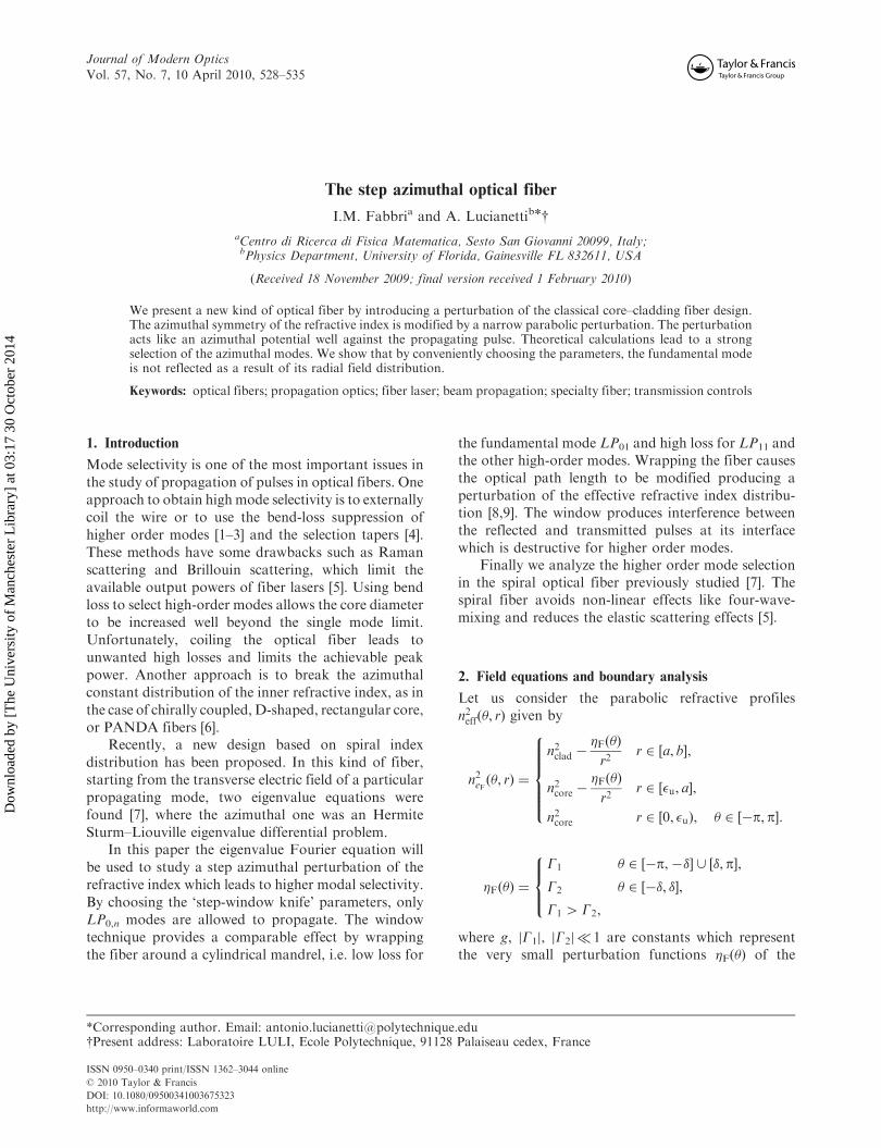
classic step index refractive profile ncore/clad. Here a is
the core radius of the fiber and �u the radius of a small
unperturbed zone (see Figure 1).The transverse electric field of a particular mode in
the fiber satisfies the scalar wave equation, which can
be written in polar coordinates r and � as
@2�
@r2þ1
r
@�
@rþ
1
r2@2�
@�2þ n2eðr, �Þk
2 � �2� �
� ¼ 0,
0 � r � 1, �p5 � � p,
k ¼!
c,
where �(r, �) is the field, k is the free-space wave-
number, and ne(r, �) is the effective refractive index
distribution.The boundary conditions associated with the field
equation due to the electric charge distribution and
finite energy are:
�ðr, �Þ 2 C1½½�p,p� � ð0,1Þ� \ L2½½�p, p� � ð0,1Þ�,
limr!1
�ðr, �Þ ¼ 0,
@�
@r
���r¼0¼ 0:
The field �(r, �) can be conveniently expressed as
�ðr, �Þ ¼ �ðrÞ f ð�Þ:
By substituting the equation of ne(r, �) into the field
equation, we obtain two eigenvalue equations
1
f ð�Þ
@2f ð�Þ
@�2� k2�Fð�Þ ¼ �W, �p5 � � p,
r2
�ðrÞ
@2�ðrÞ
@r2þ
r
�ðrÞ
@�ðrÞ
@r�Wþ n2core=cladk
2 � �2h i
r2 ¼ 0,
0 � r51:
These are the Fourier and Bessel equations,
respectively.Let’s analyze the azimuthal Fourier equation in the
following linear second-order differential form
Lf ð�Þ :¼ �f 00ð�Þ þ qð�Þ f ð�Þ ¼Wf ð�Þ:
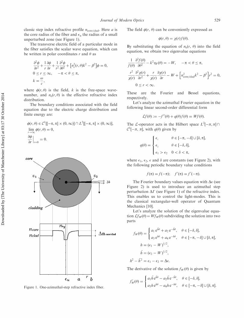
The L-operator acts in the Hilbert space L2[�,]\C1[�, ], with q(�) given by
qð�Þ ¼
�1
� 2 ½�p,��� [ ½�, p�,
�2
� 2 ½��, ��,
�1 4 �2 05 �5p,
8>><>>:
where �1, �2, � and � are constants (see Figure 2), with
the following periodic boundary value conditions
f ðpÞ ¼ f ð�pÞ; f 0ðpÞ ¼ f 0ð�pÞ:
The Fourier boundary values equation with D� (seeFigure 2) is used to introduce an azimuthal step
perturbation DG (see Figure 1) of the refractive index.
This enables us to control the light-modes. This is
the classical rectangular-well operator of Quantum
Mechanics [10].Let’s analyze the solution of the eigenvalue equa-
tion LfW(�)¼WfW(�) subdividing the solution into two
parts
fWð�Þ ¼a1 e
�h� þ a2 e� �h�, � 2 ½��, ��,
a3 eh� þ a4 e
�h�, � 2 ½�p,��� [ ½�,p�,
(
h ¼ ð�1 �W Þ1=2,
�h ¼ ð�2 �W Þ1=2,
h2 � �h 2 ¼ �1 � �2 ¼ D�:
The derivative of the solution fW (�) is given by
f 0Wð�Þ ¼a1 �h e
�h� � a2 �h e��h�, � 2 ½��, ��,
a3h eh� � a4h e
�h�, � 2 ½�p,��� [ ½�, p�:
(Figure 1. One-azimuthal-step refractive index fiber.
Journal of Modern Optics 529
Dow
nloa
ded
by [
The
Uni
vers
ity o
f M
anch
este
r L
ibra
ry]
at 0
3:17
30
Oct
ober
201
4
The identities
a3 e�hp þ a4 e
hp ¼ a3 ehp þ a4 e
�hp,
a3 e�h� þ a4 e
h� ¼ a1 e� �h� þ a2 e
�h�,
a3 eh� þ a4 e
�h� ¼ a1 e�h� þ a2 e
� �h�,
a3h e�hp � a4h e
hp ¼ a3h ehp � a4h e
�hp,
a1 �h e��h� � a2 �h e
�h� ¼ a3h e�h� � a4h e
h�,
a1 �h e�h� � a2 �h e�
�h� ¼ a3h eh� � a4h e
�h�,
8>>>>>>>><>>>>>>>>:
ensure that the boundary conditions are satisfied by
the eigenfunction fW (�).The first and the fourth identities are satisfied if
and only if sin(ih)¼ 0, i.e. h¼ im, m2Z and�hm ¼ iðm2 þ D�Þ1=2, the system reduces to
�a1 e� �hm� � a2 e
�hm� þ a3 e�im� þ a4 e
im� ¼ 0,
�a1 e�hm� � a2 e
� �hm� þ a3 eim� þ a4 e
�im� ¼ 0,
a1 �hm e��hm� � a2 �hm e
�hm� � a3im e�im� þ a4im eim� ¼ 0,
a1 �hm e�hm� � a2 �hm e�
�hm� � a3im eim� þ a4im e�im� ¼ 0,
Wm ¼ m2 þ �1:
8>>>>>>><>>>>>>>:
A non-trivial solution is obtained by imposing the
determinant D of the system to vanish, i.e.
D ¼ ð2m2 þ D�Þ sin ð2m�Þ sin 2ðm2 þ D�Þ1=2�� �
þ 2mðm2 þ D�Þ1=2
�
�cos ð2m�Þ cos 2ðm2 þ D�Þ1=2�
� �� 1
�¼ 0:
Because D�¼ k2(G1�G2)¼ (42/2)DG40, the deter-
minant D is always a real number. The fundamental
solution m¼ 0 satisfies the equation D¼ 0 and thesystem reduces to
�a1 exp½�iðD�Þ1=2�� � a2 exp½iðD�Þ
1=2�� þ a3 þ a4 ¼ 0,
�a1 exp½iðD�Þ1=2�� � a2 exp½�iðD�Þ
1=2�� þ a3 þ a4 ¼ 0,
a1iðD�Þ1=2 exp½�iðD�Þ1=2�� � a2iðD�Þ
1=2
� exp½iðD�Þ1=2�� ¼ 0,
a1iðD�Þ1=2 exp½iðD�Þ1=2�� � a2iðD�Þ
1=2
� exp½�iðD�Þ1=2�� ¼ 0:
8>>>>>>>>><>>>>>>>>>:
If we choose �, D� so that �(D�)1/2¼ (2�/)�(DG)1/2� 1 or �(DG)1/2� /2 then we can approxi-mate exp[i(D�)1/2�]’ exp[�i(D�)1/2�]’ 1, and thesystem reduces to
�a1 � a2 þ a3 þ a4 ’ 0,
a1 � a2 ’ 0:
The fundamental solution becomes f�1=21ð�Þ ’ 2a1
� 2 ½�p, p�.The same approximation for higher order modes
m� 1 leads to the system
�a1 e�im� � a2 e
im� þ a3 e�im� þ a4 e
im� ¼ 0,�a1 e
im� � a2 e�im� þ a3 e
im� þ a4 e�im� ¼ 0,
a1ðm2 þ D�Þ1=2 e�im� � a2ðm
2 þ D�Þ1=2 eim�
�a3m e�im� þ a4m eim� ¼ 0,a1ðm
2 þ D�Þ1=2 eim� � a2ðm2 þ D�Þ1=2 e�im�
�a3m eim� þ a4im e�im� ¼ 0:
8>>>>>><>>>>>>:
Then for m 6¼ 0 the factor D� can’t be completelyeliminated because it is not multiplied by � and thedeterminant becomes
D ¼ ð2m2 þ D�Þ � 2mðm2 þ D�Þ1=2 6¼ 0:
Figure 2. The function q(�).
530 I.M. Fabbri and A. Lucianetti
Dow
nloa
ded
by [
The
Uni
vers
ity o
f M
anch
este
r L
ibra
ry]
at 0
3:17
30
Oct
ober
201
4
For example, if we want the first modes to sense the
perturbation we have to choose D�’ 0.1, �� 1, which
means (DG)1/2’ /2.It is worth pointing out that the perturbation of the
refractive index G1,2/r2 is undetectable in the cladding
region where r is large (r410 mm), then the e.l.m.
well could be considered a core effect. A possible
choice DG’ 0.25� 10�14 corresponds to a perturba-tion ðjDn2jÞ1=2 ¼ ðjn2eF � n2corejÞ
1=2¼ G1=2
1 =r ’ 5� 10�2
at r¼ 1 mm and (jDn2j)1/2’ 5� 10�3 at r¼ 10 mm, an
unperturbed radius �u of a fraction of a mm and
�’ 1/36 rad.Special cases are described by the following
theorems.
Theorem 2.1: If 2m�¼s1, s12N, �52, the condi-tion D¼ 0 reduces to
cos ps1 1þD�m2
�1=2 !
¼ ð�Þs1 , 05 s1 5 4m:
The constants �1, �2 must satisfy the relation
D� ¼ m2 ‘1s1
�2
�1
" #� 1,
‘1 2 N, ‘1 � s1 even,
15‘1s1
��������� 1þ
1
m2
�1=2
5 21=2:
Proof: It is enough to solve the system
2m� ¼ ps1,
2ðm2 þ D�Þ1=2� ¼ p‘1:
œ
We observe that
052m�
p5 ‘1 5
2ð21=2Þm�
p5 4ð21=2Þm:
Theorem 2.2: If 2(m2þD�)1/2�¼s2, s22N, �52,
the condition D¼ 0 reduces to
cosmps2
ðm2 þ D�Þ1=2
�¼ ð�Þ
s2 :
The constants �1, �2 must satisfy the relation
D� ¼ m2 s2‘2
�2
�1
" #,
‘2 2 N, ‘2 � s2 even,
15��� s2‘2
���� 1þ1
m2
�1=2
5 21=2,
05 ‘2 5 4ð21=2Þm:
Proof: It is enough to solve the system
2ðm2 þ D�Þ1=2� ¼ ps2,
2m� ¼ p‘2:
(
œ
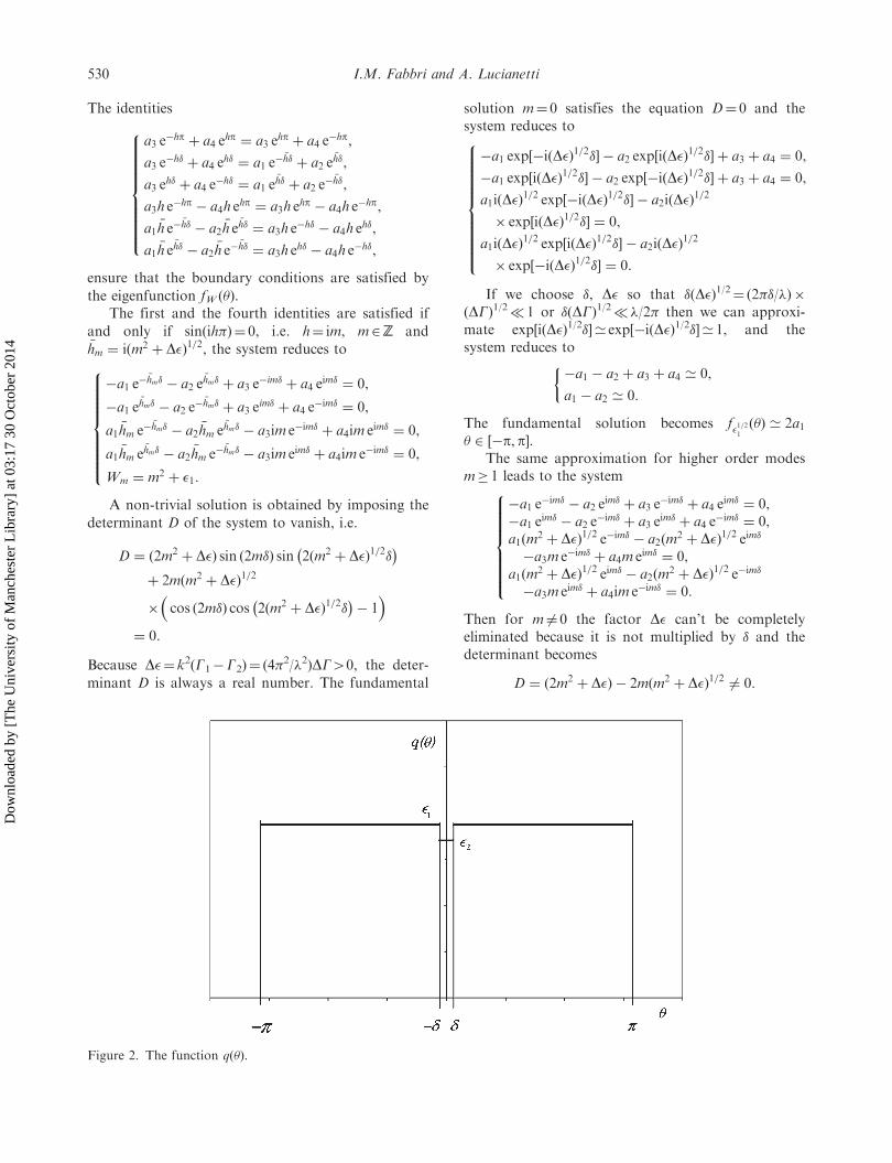
The step azimuthal window periodically introducesfurther internal refractions into the optical fiber. Assketched in Figure 3, the rays that enter the fiberintersect the core–cladding interface and strike the stepazimuthal window. Each time that the ray of a highazimuthal order mode intersects the azimuthalwindow, it undergoes a small reflection and after arelatively short optical path becomes an unboundedray, unless the geometry of the window preciselymatches the conditions described above.
Because of their radial symmetry, the modes withm¼ 0 are less sensitive to the azimuthal windowperturbation. In a standard step-index fiber with coreradius a and core and cladding indices ncore, nclad, thenumber of guided modes is determined by theV value [11]
V ¼2paðn2core � n2cladÞ
1=2:
The V number must be less than 2.405 for the classicalfiber to be single mode, while in the case of the insertionof our azimuthal window this range is larger and thenumber must be less than 3.832 which corresponds tothe mode labeled LP02. For a photonic crystal fiber theV number transforms into an effective Veff value
Veff ¼2pLðn20 � n2effÞ
1=2,
where n0 is the index of silica (the core material) andneff is determined by the propagation constant of thefundamental space-filling mode [12], the pitch of the
Figure 3. Unbound rays: angled view.
Journal of Modern Optics 531
Dow
nloa
ded
by [
The
Uni
vers
ity o
f M
anch
este
r L
ibra
ry]
at 0
3:17
30
Oct
ober
201
4
holes L theoretically ensures the fiber to be endlesslysingle mode. The limiting value of Veff depends on therelative size of the holes, smaller holes make single-mode guidance more likely but makes the fiber moresusceptible to bend loss.
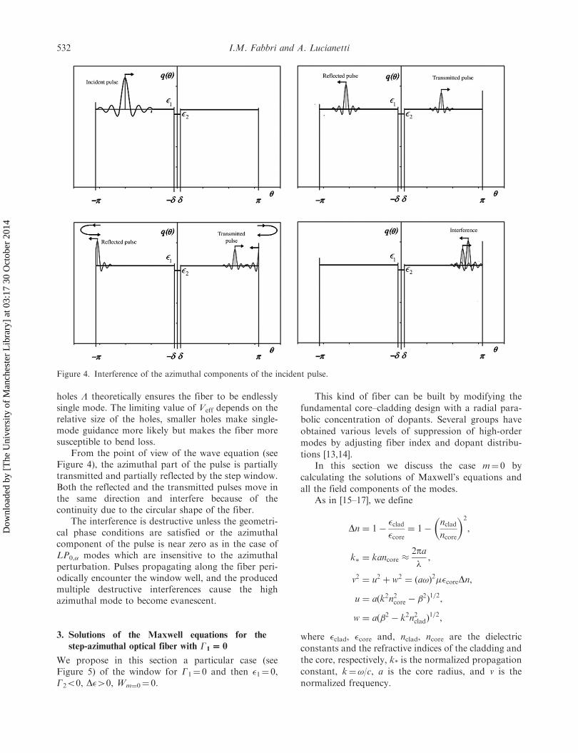
From the point of view of the wave equation (seeFigure 4), the azimuthal part of the pulse is partiallytransmitted and partially reflected by the step window.Both the reflected and the transmitted pulses move inthe same direction and interfere because of thecontinuity due to the circular shape of the fiber.
The interference is destructive unless the geometri-cal phase conditions are satisfied or the azimuthalcomponent of the pulse is near zero as in the case ofLP0,� modes which are insensitive to the azimuthalperturbation. Pulses propagating along the fiber peri-odically encounter the window well, and the producedmultiple destructive interferences cause the highazimuthal mode to become evanescent.
3. Solutions of the Maxwell equations for the
step-azimuthal optical fiber with G1^ 0
We propose in this section a particular case (seeFigure 5) of the window for G1¼ 0 and then �1¼ 0,G250, D�40, Wm¼0¼ 0.
This kind of fiber can be built by modifying the
fundamental core–cladding design with a radial para-
bolic concentration of dopants. Several groups have
obtained various levels of suppression of high-order
modes by adjusting fiber index and dopant distribu-
tions [13,14].In this section we discuss the case m¼ 0 by
calculating the solutions of Maxwell’s equations and
all the field components of the modes.As in [15–17], we define
Dn ¼ 1��clad�core¼ 1�
ncladncore
�2
,
k� ¼ kancore 2pa
,
v2 ¼ u2 þ w2 ¼ ða!Þ2��coreDn,
u ¼ aðk2n2core � �2Þ
1=2,
w ¼ að�2 � k2n2cladÞ1=2,
where �clad, �core and, nclad, ncore are the dielectric
constants and the refractive indices of the cladding and
the core, respectively, k* is the normalized propagation
constant, k¼!/c, a is the core radius, and v is the
normalized frequency.
Figure 4. Interference of the azimuthal components of the incident pulse.
532 I.M. Fabbri and A. Lucianetti
Dow
nloa
ded
by [
The
Uni
vers
ity o
f M
anch
este
r L
ibra
ry]
at 0
3:17
30
Oct
ober
201
4

Assuming Dn� 1 we have a simplification in
matching the field components at the core–cladding
interface [15] and we use the Cartesian coordinates
in order to express the components of the field
vectors.We may express E� in term of Ex and Ey as
E� ¼ �Ex sin � þ Ey cos �:
Thus, the continuity of E� is equivalent to the conti-
nuity of Ex or Ey.The y-polarized solutions are expressed in the
following form: Core (�u5r5a)
Exðr, �, z, tÞ ¼ 0,
Eyðr, �, z, tÞ ¼ AJ0u
ar
� �exp½ið!t� �zÞ�,
Ezðr, �, z, tÞ ¼ �Aiu
a�sin �J 00
u
ar
� �exp½ið!t� �zÞ�,
Hxðr, �, z, tÞ ¼ ��
!�AJ0
u
ar
� �exp½ið!t� �zÞ�,
Hyðr, �, z, tÞ ’ 0,
Hzðr, �, z, tÞ ¼ Aiu
a!�cos �J 00
u
ar
� �exp½ið!t� �zÞ�:
Cladding (r4a)
Exðr, �, z, tÞ ¼ 0,
Eyðr, �, z, tÞ ¼ BK0w
ar
� �exp½ið!t� �zÞ�,
Ezðr, �, z, tÞ ¼ �Biw
a�sin �K 00
w
ar
� �exp½ið!t� �zÞ�,
Hxðr, �, z, tÞ ¼ ��
!�BK0
w
ar
� �exp½ið!t� �zÞ�,
Hyðr, �, z, tÞ ’ 0,
Hzðr, �, z, tÞ ¼ Biw
a!�cos �K 00
w
ar
� �exp½ið!t� �zÞ�:
Unperturbed zone (0� r5�u)
Exðr, �, z, tÞ ¼ 0,
Eyðr, �, z, tÞ ¼ AJ0u
ar
� �exp½ið!t� �zÞ�,
Ezðr, �, z, tÞ ¼ �Aiu
a�sin �J 00
u
ar
� �exp½ið!t� �zÞ�,
Hxðr, �, z, tÞ ¼ ��
!�AJ0
u
ar
� �exp½ið!t� �zÞ�,
Hyðr, �, z, tÞ ’ 0,
Hzðr, �, z, tÞ ¼ Aiu
a!�cos �J 00
u
ar
� �exp½ið!t� �zÞ�:
Figure 5. A special case with "1¼ 0 and "250.
Journal of Modern Optics 533
Dow
nloa
ded
by [
The
Uni
vers
ity o
f M
anch
este
r L
ibra
ry]
at 0
3:17
30
Oct
ober
201
4
The field of the perturbed fiber does not change
with respect to the unperturbed one. The x-polarized
solution is analogous. The continuity condition for Ey
at the core boundary gives the constant B:
B ¼ AJ0ðuÞ
K0ðwÞ:
The constant A is then determined by the normaliza-
tion condition. By considering the continuity of Ez at
r¼ a, we obtain the following mode condition
uJ 00ðuÞ
J0ðuÞ¼ w
K 00ðwÞ
K0ðwÞ:
The mode field is continuous with its derivative at the
interface with the small unperturbed zone.The time averaged Poynting vector along the
waveguide is
Sz ¼1
2<ðExH
�y � EyH
�x Þ:
Substituting the field components we obtain
Sz ¼
�
!�jAj2J20
u
ar
� �, �u 5 r5 a,
�
!�jBj2K2
0
w
ar
� �, r4 a:
8>><>>:
The amount of power that is contained in the core/
cladding and in the unperturbed region is given by
Pcore ¼
ð2p0
ða�u
Szr dr d�,
Pclad ¼
ð2p0
ð1a
Szr dr d�,
Pun ¼
ð2p0
ð�ua
Szr dr d�:
Using some classical integrals of Bessel functions
[18], the powers Pcore, Pclad, and Pun can be written as:
Pcore ¼�
2!�pa2jAj2½J20ðuÞ þ J21ðuÞ� � Pun,
Pclad ¼�
2!�pa2jBj2½�K2
0ðwÞ þ K21ðwÞ�,
Pun ¼�
2!�p�2ujAj
2 J20u
a�u
� �þ J21
u
a�u
� �h i:
The total power flow is thus given by
P ¼�
2!�pa2jAj2
"J21ðuÞ þ
J20ðuÞK21ðwÞ
K20ðwÞ
#� Pun:
It is worth pointing out that
lim�u!0
Pun ¼ 0:
Note that the expression of the power for the funda-
mental mode is identical to the classical step azimuthal
fiber case [19].
4. High-order modes for the spiral optical fiber
In a previous paper [7] the spiral optical fiber was
initially studied in fundamental mode operation, and
the solution was obtained in terms of the Hermite func-
tions in � and Bessel’s in r. In Cartesian coordinates
these kinds of perturbations are also known as ‘a square
law medium for a lens waveguide’ [19].Because of the particular polynomial dependence of
the fields in the angle �, the matching conditions are
possible only for pure TE or pure TM mode.In order to propagate the fundamental mode, the
g value of the spiral perturbation must be
315 g5 2:2:
In order to propagate the higher order modes, the
azimuthal continuity of the e.l.m. field must be
satisfied. According to the solution of the azimuthal
Hermite eigenvalue equation [20], the gp, j perturbation
values must satisfy the relation
gp, j ¼
2
tp, j
p2, p even:
Hence, the solution in the core region is
Ez
Hz
� ¼
A
B
� JðWp, jÞ
1=2
u
ar
� �Hp �
!gp, jc
� �1=2�
� exp �!gp, j2c
�2� �
, r5 a � p5 � � p:
and in the cladding region
Ez
Hz
� ¼
C
D
� KðWp, jÞ
1=2
w
ar
� �Hp �
!gp, jc
� �1=2�
� exp �!gp, j2c
�2� �
, r4 a � p5 � � p:
The eigenvalues are
Wp, j ¼ 2vp, j pþ1
2
�:
The v values must satisfy the following equation
vp, j ¼ðtp, jÞ
2
p2:
534 I.M. Fabbri and A. Lucianetti
Dow
nloa
ded
by [
The
Uni
vers
ity o
f M
anch
este
r L
ibra
ry]
at 0
3:17
30
Oct
ober
201
4
where the points �¼ tp, j are in the range [20],
��p, j 5 tp, j 5 �þp, j,
�p, j ¼ ð2pþ 1Þ1=2 cos ð ~Fp, jÞ Oð1=pÞ,
~Fp, j ¼~Tpj2þX1p¼1
Jpð pÞ
psin ð p ~Tpj Þ,
~Tpj ¼�2þ 3þ 4j
2pþ 1p, j � 1:
The complete solution of the wave equation [7] canthen be expressed in terms of the longitudinal fields.
5. Conclusion
In this paper a new type of perturbation of therefractive index for optical fiber has been proposed.The classical Fourier equation with special boundaryvalues was used in order to solve the Maxwellequations. The purpose of the work is to theoreticallyintroduce an azimuthal step index optical window inthe classical core/cladding fiber. The window acts as anextremely high selector of azimuthal modes allowingone to achieve high peak powers in single modeoperation.
We have found that for a thin window �� 1, thelower azimuthal mode for m¼ 0 is a solution of theazimuthal Fourier equation, while for m40 a strictrule of selection between the parameters D�, � must besatisfied. Moreover, for m� 1 the propagating modesencounter a small well and destructive interferencephenomena limit their propagation along the fiber.
References
[1] Limpert, J.; Schreiber, T.; Nolte, S.; Zellmer, H.;
Tunnermann, T.; Iliew, R.; Lederer, F.; Broeng, J.;
Vienne, G.; Petersson, A.; Jakobsen, C. Opt. Express
2003, 11, 818–823.
[2] Koplow, J.P.; Kliner, D.A.V.; Goldberg, L. Opt. Lett.2000, 25, 442.
[3] Clarkson, W.A.; Cooper, L.J.; Wang, P.; Williams, R.B.;Sahu, J.K. Trends Opt. Photon. 2003, 83, 261–267.
[4] Alvarez-Chavez, J.A.; Grudinin, A.B.; Nilsson, J.;Turner, P.W.; Clarkson, W.A. Mode Selection in High
Power Cladding Pumped Fiber Lasers with TaperedSection. In Conference on Lasers and Electro-Optics;OSA Technical Digest; Optical Society of America:
Washington, DC, 1999; pp 247–248.[5] Agrawal, G.P. Nonlinear Fiber Optics, 2nd ed.;
Academic: New York, 1995.
[6] Tunnermann, A.; Schreiber, T.; Roser, F.; Liem, A.;Hofer, S.; Zellmer, H.; Nolte, S.; Limpert, J. J. Phys. B:At. Mol. Opt. Phys. 2005, 38, S681–S693.
[7] Fabbri, I.M.; Lauto, A.; Lucianetti, A. J. Opt. A: Pure
Appl. Opt. 2007, 9, 963–971.[8] Marcuse, D. Appl. Opt. 1982, 21, 4208–4213.[9] Marcuse, D. J. Opt. Soc. Am. 1976, 66, 311–320.
[10] Cohen-Tannoudji, C.; Diu, B.; Laloe, F. QuantumMechanics; Wiley: New York, 1977.
[11] Snyder, A.W.; Love, J.D. Optical Waveguide Theory;
Chapman Hall: New York, 1983.[12] Birks, T.A.; Knight, J.C.; Russell, P.St.J. Opt. Lett.
1997, 22, 961–963.
[13] Offerhaus, H.L.; Broderick, N.G.; Richardson, D.J.;Sammut, R.; Caplen, J.; Dong, L. Opt. Lett. 1998, 23,1683–1685.
[14] Sousa, J.M.; Okhotnikov, O.G. Appl. Phys. Lett. 1999,
74, 1528–1530.[15] D. Gloge, D. Appl. Opt. 1971, 10, 2252–2258.[16] Snyder, A.W. IEEE T. Microw. Theory 1969, 17,
1130–1138.[17] Snitzer, E. J. Opt. Soc. Am. 1961, 51, 491–498.[18] Watson, G.N. A Treatise on the Theory of Bessel
Functions, 2nd ed.; Cambridge University Press:Cambridge, UK, 1966.
[19] Marcuse, D. Light Transmission Optics, 2nd ed.;
Van Nostrand Reinhold: New York, 1982.[20] Fabbri, I.M.; Lucianetti, A.; Krasikov, I. On a Sturm–
Liouville Periodic Boundary Values Problem. IntegralTransforms and Special Functions 2009, 20, 353–364.
[21] Szego, G. Orthogonal Polynomials; AMS ColloquiumSeries, 4th ed.; American Mathematical Society:Providence, RI, 1975; Vol. 23.
Journal of Modern Optics 535
Dow
nloa
ded
by [
The
Uni
vers
ity o
f M
anch
este
r L
ibra
ry]
at 0
3:17
30
Oct
ober
201
4