Embed Size (px)
Citation preview
DOE/ID/12079--95
DE84 012192
THE STRATIGRAPHY AND STRUCTURE OF THE McCOY GEOTHERMAL PROSPECT, CHURCHILL AND LANDER COUNTIES, NEVADA
by
Michael Curtis Adams
June 1982
Work performed under Contract Number: DE-AC07-80ID12079
EARTH SCIENCE LABORATORY University of Utah Research Institute
Salt Lake City, Utah
Prepared for U.S. Department of Energy
Division of Geothermal Energy
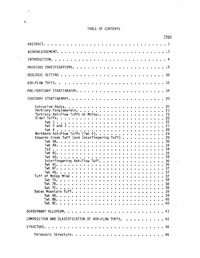
TABLE OF CONTENTS
ABSTRACT.
ACKNOWLEDGEMENT.
INTRODUCTION.
PREVIOUS INVESTIGATIONS.
GEOLOGIC SETTING
ASH-FLOW TUF FS.
PRE-TERTIARY STRATIGRAPHY.
TERTIARY STRATIGRAPHY.
Extrusive Rocks. Tertiary Fanglomerate. Tertiary Ash-Flow Tuffs at McCoy •• Older Tuffs.
Twt 1 • Twt 2 and 3 • Twt 4 •
Northern Ash-Flow Tuffs (Twt 5). Edwards Creek Tuff (and Interfingering
Twt 6A. Twt 6B. Ts2 • Twt 6C. Twt 60.
. .
Interfingering Ash-Flow Tuff. Twt 6E. Twt 6F. Twt 6G.
Tuff of McCoy Mine. Twt 7A. Twt 7B. Twt 7C.
•
Bates Mountain Tuff. Twt BA. Twt BB. Twt BC.
QUATERNARY ALLUVIUM.
•
Tuff)
COMPOSITION AND CLASSIFICATION OF ASH-FLOW TUFFS.
STRUCTURE.
Paleozoic Structure.
1
.3
• 4
.9
10
12
18
20
20 21 21 22 22
• 27 28
• 29 29
• 30 34
• 34 35
• 35 36
• 36 37
• 37 37 38 3B
• 38 39
• 39 • 40 • 40
41
• 42
46
• 46
Mesozoic Structure. Tertiary Structure.
GEOLOGIC HISTORY. •
SOURCES FOR THE ASH-FLOW TUFFS AT McCOY •
ALTERATION AND MINERALIZATION.
HEAT FLOW AND SURFACE HOT WATER DEPOSITS.
DISCUSSION.
Trend 1 • Trend 2 • Trends 3 and 4. Trend 5 • '.
CONCLUSIONS •
APPEND I X. •
REFERENCES. •
•
•
•
•
Page
.46
.47
.51
.55
.59
.60
.62
• .62 . .62 • • .64
• • .65
• .67
• • .69
• .81
Figure
1.
2.
3.
4.
5.
6.
7.
8.
9.
10.
LIST OF ILLUSTRATIONS
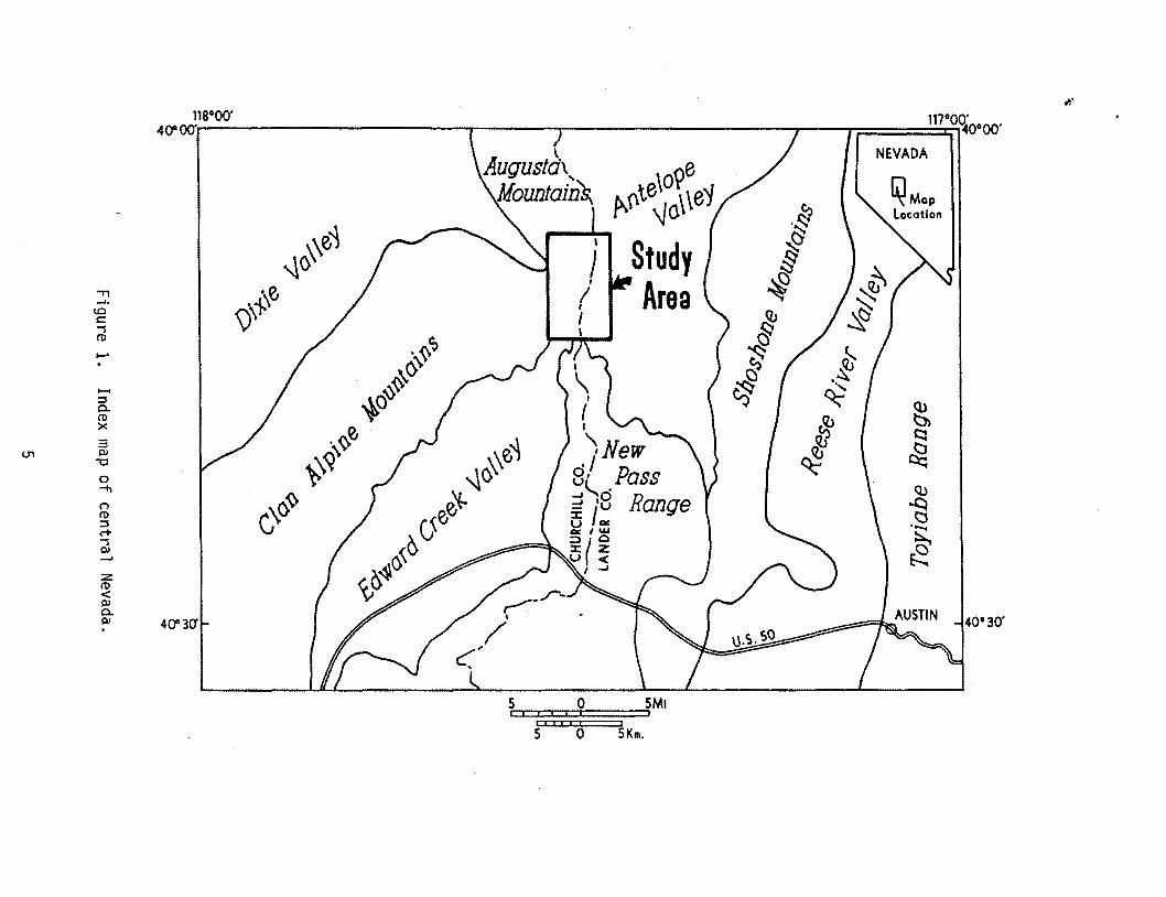
Index map of central Nevada. . . . . . . . . . . . • .5
Contoured heat flow at McCoy geothermal prospect •• . . . • • .6
Location of shallow thermal gradient holes. · . . • • • .7
Zonation of ash-flow tuffs ••• . . . · . . • 13
Classification of ash-flow tuffs •• · . . • • 16
· . • • • • • 31 Correlation of map units ••••••
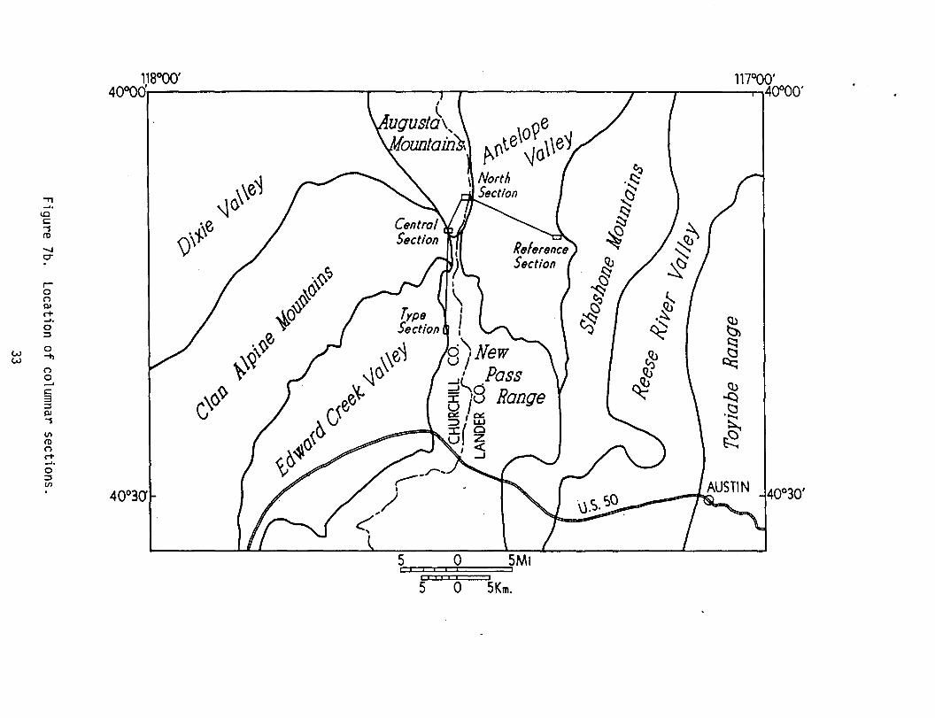
a} Columnar sections •••••••• b) Location of columnar sections ••
.. . . . • • • • 32 . . . . . . . • • • • 33
Sample locations • . . . . . . . . . . . . . · . . . . · . . • 43
Ternary diagram of normative feldspars . . . . . . • • • • • • 45
Faults with displacement greater than 70 m • · . . . " . . . • 48
11. Faults with displacement less than 70 m. · . • • 49
12.
13.
Geologic history •••• . . . . . . . . · . Tertiary volcanic centers near the McCoy prospect. · .
• • 52
• • 56
14. Structural trends associated with heat flow and surface thermal deposits ••••••••••••••••••••••••••• 63
15. Contoured mercury concentrations from drill chips. · . • • • • 66
16. Location of stratigraphic sections •••••••• • • 70
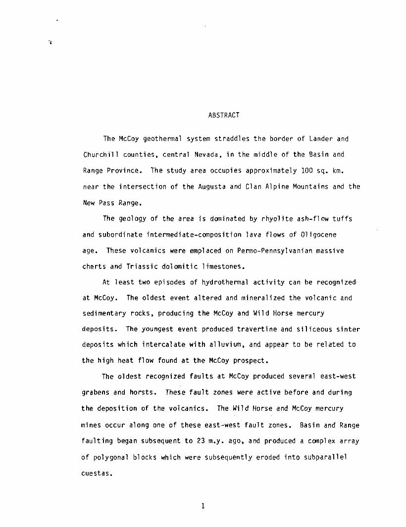
ABSTRACT
The McCoy geothermal system straddles the border of Lander and
Churchill counties, central Nevada, in the middle of the Basin and
Range Province. The study area occupies approximately 100 sq. km.
near the intersection of the Augusta and Clan Alpine Mountains and the
New Pass Range.
The geology of the area is dominated by rhyolite ash-flow tuffs
and subordinate intermediate-composition lava flows of Oligocene
age. These volcanics were emplaced on Permo-Pennsylvanian massive
cherts and Triassic dolomitic limestones.
At least two episodes of hydrothermal activity can be recognized
at McCoy. The oldest event altered and mineralized the volcanic and
sedimentary rocks, producing the McCoy and Wild Horse mercury
deposits. The youngest event produced travertine and siliceous sinter
deposits which intercalate with alluvium, and appear to be related to
the high heat flow found at the McCoy prospect.
The oldest recognized faults at McCoy produced several east-west
grabens and horsts. These fault zones were active before and during
the deposition of the volcanics. The Wild Horse and McCoy mercury
mines occur along one of these east-west fault zones. Basin and Range
faulting began subsequent to 23 m.y. ago, and produced a complex array
of polygonal blocks which were subsequently eroded into subparallel
cuestas.
1
Fluid movement in the geothermal system is controlled by the
intersections of the east-west and north-south faults. There is no
known igneous source for the thermal energy in this system. However
its intramontane location is atypical of known geothermal systems in
the Basin and Range, which may preclude deep circulation through major
basin-bounding faults.
2
ACKNOWLEDGEMENT
This project was funded by the Department of Energy under contract DE
AC07-80ID12079. My thanks go to the scientific and support staff of Earth
Sci ence Labora tory.
3
INTRODUCTION
West-central Nevada is an area of high potential for geothermal
energy. The McCoy geothermal prospect, one of several geothermal
systems within this region, is the subject of this study (Fig. 1).
The McCoy geothermal prospect was discovered in the mid-1970's by the
geothermal resource division of Amax Inc. A detailed geologic map was
required for accurate modeling of the large amount of geophysical and
geochemical data that resulted from their exploration, and to
delineate the structures which control subsurface permeability. This
report describes the geology of the area, mapped at a scale of
1:24,000, from which the detailed geophysical data were collected.
The study area also encompasses the thermal anomalies defined by a
series of shallow thermal gradient holes (Fig. 2, 3).
The McCoy geothermal prospect. found on the basis of its mercury
mineralization, is characterized by heat flow anomalies, thermal
fluids at depth, and one of the largest travertine mounds known in the
western United States. In contrast to most of the known geothermal
resources in the Basin and Range province, which appear to be related
to deep circulation along major faults, the McCoy prospect is situated
in lowlands at the juncture of three mountain ranges (Fig. 1), far
from the bounding faults of any major basin.
The McCoy area is covered to a large extent by ash-flow tuffs,
which provide unique stratigraphic marker horizons allowing structures
4
"" 118°00' 117°O<{ooOO' 4()100'
NEVADA l AUgUS!d\ Mountain~
~ .§1 ~\e~ ~
§ ~() ~ .."
\>\~e ~
..... !.O c:
~ ~ -s
. ~ (l)
~ ...... ~~
.~ .
. ~ ~ ~
~ .....
~Q~ ~
:::I c..
I s::::
ro e,.
'-, New i1 ~ x 3 .~
~ III :.:~\ g/ Pass -0
~ Q.)
0 ;!)g Range ~ ""'+!
. \C>~ n ::c ~ ...... ro G };l,w
~ :::I
=>(Q rt ::c z
~ -s
U < III
I ...J
...... Z (l) < III c.. III 4()130' 40'30'
5 0 I I I j I i
S' I I I 6 ~Km.
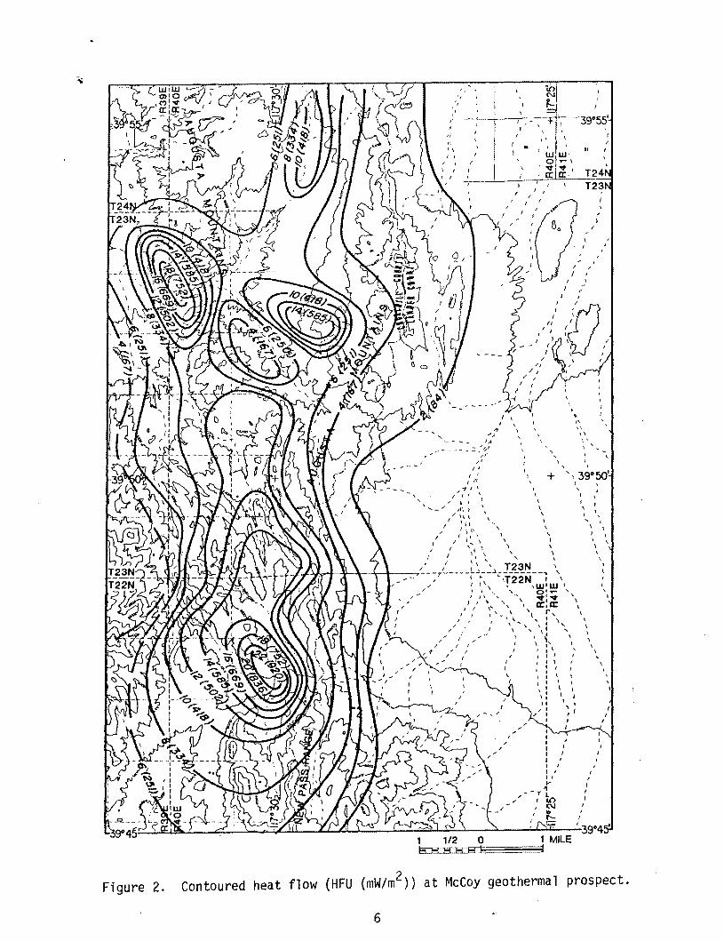
Figure 2.
" ;;
- - ... " '''' ... :- :>/1 J
" I I
/ ,
I I
, I
\
\
, I
+
, \
\
I
\ \
I I I I I I I
I I I I
" '"
; I
/--71 ; ,a,()
IN .. ..... e::::
, /
I
\ '
• , 1\
"
I ' I
\ , I' I '_
I , I
,39°50' I
, (
(
, I
\ \
\
\
I I I
)
I
I
t , ,
\
\
\ \
I
I
, ,
,
,
,
\ , ,
1 1/2 0 1 MILE 8EoHED8ED8EDH~I~~~~~1
contoured heat flow (HFU (mW/m2)) at McCoy geothermal prospect.
6
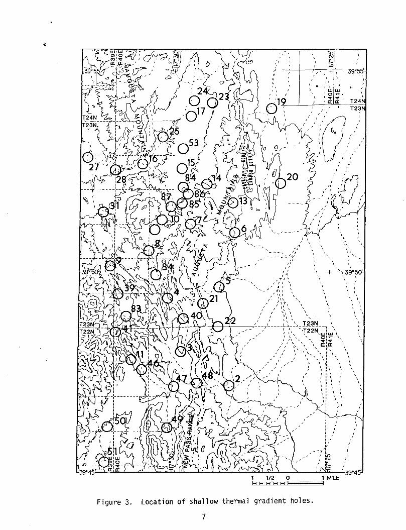
Figure 3.
" , , I
" " /I
" I, , I
I
"
" ,.-, , J~
_ - - - - _ :; :'il II
, ,
" I , ( , I"
-,'" I I I (I \
• I 1111
I" \\ C.
I
I \ 1\ I \ \' \
" ,~ \ "
I
I
, \
I 'I' \ I I 1, \ ,
.. \
I
, , , , \ \
,
\ ,
-.0 N ~
, " ( I
W 0 ~ a:
, ,
\ , \
,
+
\ I \ \
39°55'
I
" I W, .- , ~ a:
I
, ,
T24 T23
\
/
I
\ J
I ,
• ~
I'
" " I' , , ,
, , , 39°50' I , , I
\
I
I
\ ,
, \ , ,
,'/ I, \ T23N ..y~"--t-+---J,,-----':---7 _____ L-,, __ :; __ ------
{' 'IT22N ~ \
\ \
,., I I', 'd.Lj'UJ I
/ J\ \. \. 0:"'- \. '\ J I" '. \ V,"" \
I I " '\ \ a:: I a:: I , ,,\ 'l r,
,,' I \" .... , '\ : l\.
,. ( \" \ I "
/
I
I \ ~ \
/ , " 1\ , I I , 1\
, I
: \ I I ,
\: \ \ I I II
I I I I
I I I I I I ' I , I I
I' ... ... --71
I It) ,I(\J
~ = 1 1/2 0 1 MILE HEcEHCEH[EHLEH~I~~~~~1
, (
Location of shallow thermal gradient holes.
7
\
!
\
\
I i I
, , ,
f
f
I
,
f , , ,
\ \ ,
\
to be mapped in detail throughout the area. The mapping was done on
aerial photographs and the volcanic units were correlated on the basis
of petrography and textures. Spectrochemical oxide analyses and model
compositions were determined for the ash-flow tuffs in order to
compare them on a regional basis.
The area can be reached by dirt and gravel roads suitable for
most passenger cars. U.S. 50 and state highway 8A are the nearest
paved roads, both leading to Austin, Nevada, approximately 50 air
kilometers southeast of the mapped area. The climate of the region is
semi-arid and no permanent surface water exists within the mapped
area. Vegetation consists of sagebrush and sparse juniper trees in
the lower reaches, with the junipers becoming plentiful at higher
elevations. The mapped area straddles the Lander County-Churchill
County line, covering all of township 23 north, range 40 east, and 13
sections in township 22 north, range 40 east, Mount Diablo base
meridian.
8
PREVIOUS INVESTIGATIONS
Little scientific work was done in the McCoy area prior to
1942. After the establishment of the McCoy and Wild Horse Mercury
Mines, in 1916 and 1939, respectively, a strategic minerals
investigation of the mine area was initiated by the U.S. Geological
Survey (Dane and Ross, 1942). Although their interpretations of
structures in the pre-Tertiary strata are similar to those described
in this report, they were handicapped by the state of the art in ash
flow tuff studies and there are major differences in the structural
interpretation of these units.
The sedimentary stratigraphy was locally defined by Dane and Ross
in 1942 (Dane and Ross, 1942). It was later redefined for county
geologic maps by Speed (in Stewart et al., 1977) and Willden (Willden
and Speed, 1974) whose work was partly based on the work of Muller et
ale {1951}. The volcanic units in the McCoy area were first defined
by McKee and Stewart (1971) in an effort to systematize the ash-flow
tuff stratigraphy of central Nevada by K-Ar age dating and
lithology. Other works relating these ashes to the Oligocene volcano
tectonic regime of central Nevada are those of Riehle et al. (1972)
and Burke and McKee (1979).
A summary of the geophysical and geochemical surveys done by Amax
Exploration, Inc. was given by Olsen et ale (1979).
9
GEOLOGIC SETTI NG
The McCoy geothermal prospect lies near the center of the Basin
and Range physiographic province. The study area is surrounded by
several Tertiary volcanic and Mesozoic plutonic complexes. The Fish
Creek caldera (McKee, 1970) and the Mount Lewis cauldron (Wrucke and
Silberman, 1975) border the western and eastern margins of northern
Antelope Valley, respectively (Fig. 1). Southwest of McCoy, in the
Clan Alpine Mountains, rhyolite domes, lava flows, and ash-flow tuffs
fill a large volcano-tectonic depression (Riehle et al., 1972). Two
Mesozoic plutonic complexes in this region are the Stillwater Gabbro
Complex, in the Stillwater Range, and the Austin Pluton, in the
Toiyabe Range (Willden and Speed, 1974; Stewart et al., 1977) (Fig.
1) •
The oldest rocks at McCoy are Paleozoic (Dane and Ross, 1942).
These consist of massive bedded cherts, sandstones, and conglomerates
which were tightly folded and thrust over contemporaneous carbonate
facies rocks during the Sonoma Orogeny. The Paleozoic rocks are
overlain unconformably by a thick sequence of Triassic limestones and
dolomitic limestones, themselves gently folded during the Nevadan
Orogeny (Willden and Speed, 1974). After peneplanation, during the
late Mesozoic and early Tertiary, Oligocene volcanics covered the pre
Tertiary rocks. The only area at McCoy where pre-Basin and Range
Tertiary tectonism was recognized is near the Wild Horse and McCoy
10
Mercury Mines. Faulting in this locale resulted in the formation of
thick fanglomerates (Dane and Ross, 1942) and controlled the
distribution of several ash-flow tuff sheets. Basin and Range
faulting in the McCoy area produced a series of polygonal rotated
blocks, which dip from 10 to 40° eastward. Quaternary hydrothermal
activity resulted in travertine and siliceous sinter. These surficial
thermal deposits are coeval with Quaternary alluvium.
11
ASH-FLOW TUFFS
Over 70% of the exposed rocks at McCoy are ash-flow tuffs. These
units provide good marker beds for stratigraphic correlation.
Geologically, emplacement of each cooling unit is isochronous yielding
horizons which enable one to work out the geometry and chronology of
faults with high precision (Mackin, 1960). To utilize ash-flow tuffs
in this fashion two post-depositional changes must be taken into
account, welding and crystallization (Smith, 1960; Ross and Smith,
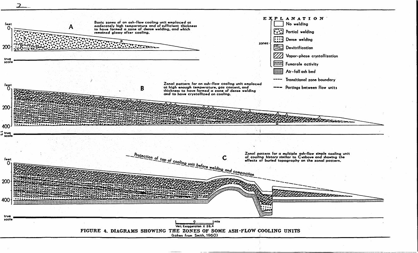
1961). Lateral and vertical zonation resulting from these processes
were described by Smith (1960) and are reproduced in Fig. 4.
As an ash-flow is emplaced the shards are frequently hot and
plastic, and the lower portion of the flow compresses and welds if the
pressure of the overlying ash is sufficient. In many sheets the base
and top are often cooled rapidly enough to prevent welding, while in
the interior of the flow, welding is typically at a maximum.
Differences in the degree of welding led Smith (1960) to recognize
three zones, shown in Fig. 4A as a) the non-welded zone, b) the
partially welded zone, and c) the densely welded zone.
The appearance of an ash-flow sheet may also be affected by
crystallization. Crystallization;-n ash-flow tuffs results from the
presence of volatiles and elevated temperatures. The two types of
crystallization, primary devitrification and vapor phase
crystallization, are synchronous with the welding process.
12
feet
o Basic zones of on ash-Flow cooling unit emplaced at
A moderately high temperature and of sufficient thlckne .. 8'lr- to have formed a zone of dense welding, and which ' •••• ~"'wY- __ .... _ remained glassy after cooling • ...... .; ....... : ..................... --.
200
EXPLANATION [:J No welding
E!::J Partial welding
E :: :1 Dense welding zones
§J DevitrlFication
true .. ________________________________________________________________________________ .... ________ _
scale
~ Vapor-phase crystallization
~ Fumarole activity
feet o
200
400
-~
Yo
~ ~~ !"'" .... -~ ~
=-..~~~ ~!':' ..... .........
B
•••
Zonal pattern For on ash-flow cooling unit emplaced ·at high enough temperature, gas content, and thlclenell to have formed a zone of den.e welding and to have crystallized on cooling.
c
111m!!!ml Air - Fa" ash bed
a
Transitional zone boundary
Partings between flow units
~true ..................................... ________________________________________________________________________________ .~\--------------------------------------------------------------~ scale
feet o
200
400
--I!!EJectlan F -- ° top F ---- ° COol' c Zonal pottern for a multiple o.h-flow simple cooling unit
of cooling hl.tory similar to C~bove and ,hawing the eFfects of burled topography on the zonal pottern.
---!!!.'!J!ntt b f, - - !..ore we/c/' - __ Ing and
----..£Ontpoct' _---_-~--~n --------------
true ............................................................... ____ .. ______________________________________________________ ~~ ________________________________ .... ______ .... ____ .... __________ _ scale o lmlle
I
Vert. Eloooerotion X 26.4
FIGURE 4. DIAGRAMS SHOWING THE ZONES OF SOME ASH -FLOW COOLING UNITS (token from Smith. 1960)
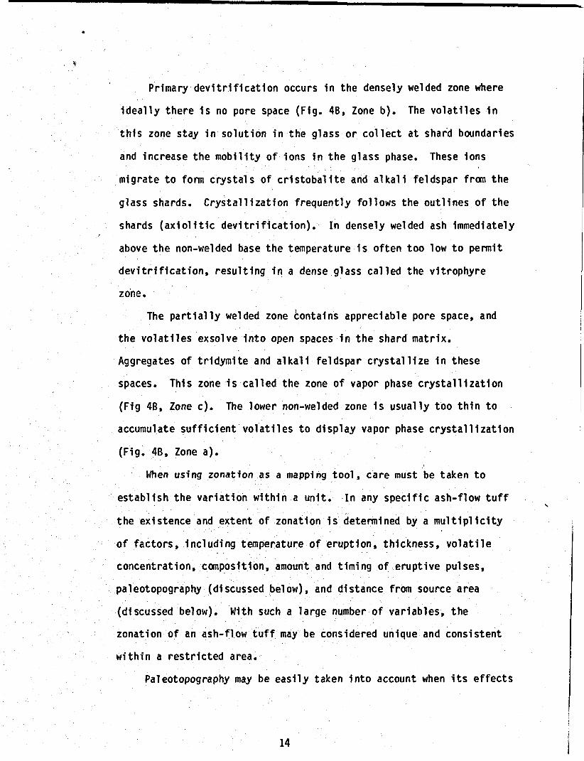
Primary devitrification occurs in the densely welded zone where
ideally there is no pore space (Fig. 48, Zone b). The volatiles in
this zone stay in solution in the glass or collect at shard boundaries
and increase the mobility of ions in the glass phase. These ions
migrate to fonn crystals of cristobalite and alkali feldspar from the ,
glass shards. Crystallization frequently follows the outlines of the
shards (axiolitic devitriflcation). In densely welded ash immediately
above the non-welded base the temperature is often too low to pennit
devitr1f1cat10n, resulting in a dense glass called the vitrophyre
zo'ne.
The partially welded zone contains appreciable pore space, and
the volatiles exsolve into open spaces in the shard matrix.
Aggregates of tridymite and alkali feldspar crystallize in these
spaces. This zone 1s called the zone of vapor phase crystallization
(Fig 48, Zone c). The lower non-welded zone is usually too thin to
accumulate sufficient volatiles to display vapor phase crystallization
(Fig. 48, Zone a).
When using zonation as a mapping tool, care must be taken to
establish the variation within a unit. In any specific ash-flow tuff
the existence and extent of zonation is detenn1ned by a multiplicity
of factors, including temperature of eruption, thickness, volatile
concentration, composition, amount and timing of eruptive pulses,
paleotopography (discussed below), and distance from source area
(discussed below). With such a large number of variables, the
zonation of an ash-flow tuff may be considered unique and consistent
within a restricted area.
Paleotopography may be easily taken into account when its effects
14
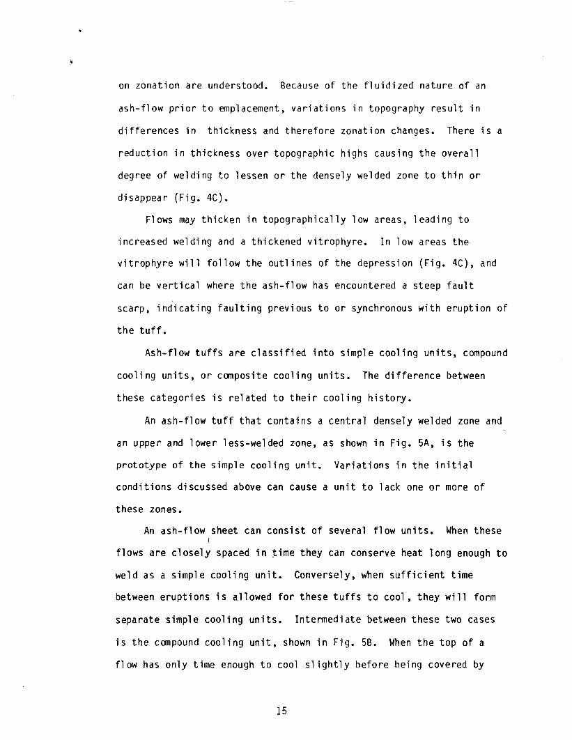
on zonation are understood. Because of the fluidized nature of an
ash-flow prior to emplacement, variations in topography result in
differences in thickness and therefore zonation changes. There is a
reduction in thickness over topographic highs causing the overall
degree of welding to lessen or the densely welded zone to thin or
disappear (Fig. 4C).
Flows may thicken in topographically low areas, leading to
increased welding and a thickened vitrophyre. In low areas the
vitrophyre will follow the outlines of the depression (Fig. 4C), and
can be vertical where the ash-flow has encountered a steep fault
scarp, indicating faulting previous to or synchronous with eruption of
the tuff.
Ash-flow tuffs are classified into simple cooling units, compound
cooling units, or composite cooling units. The difference between
these categories is related to their cooling history.
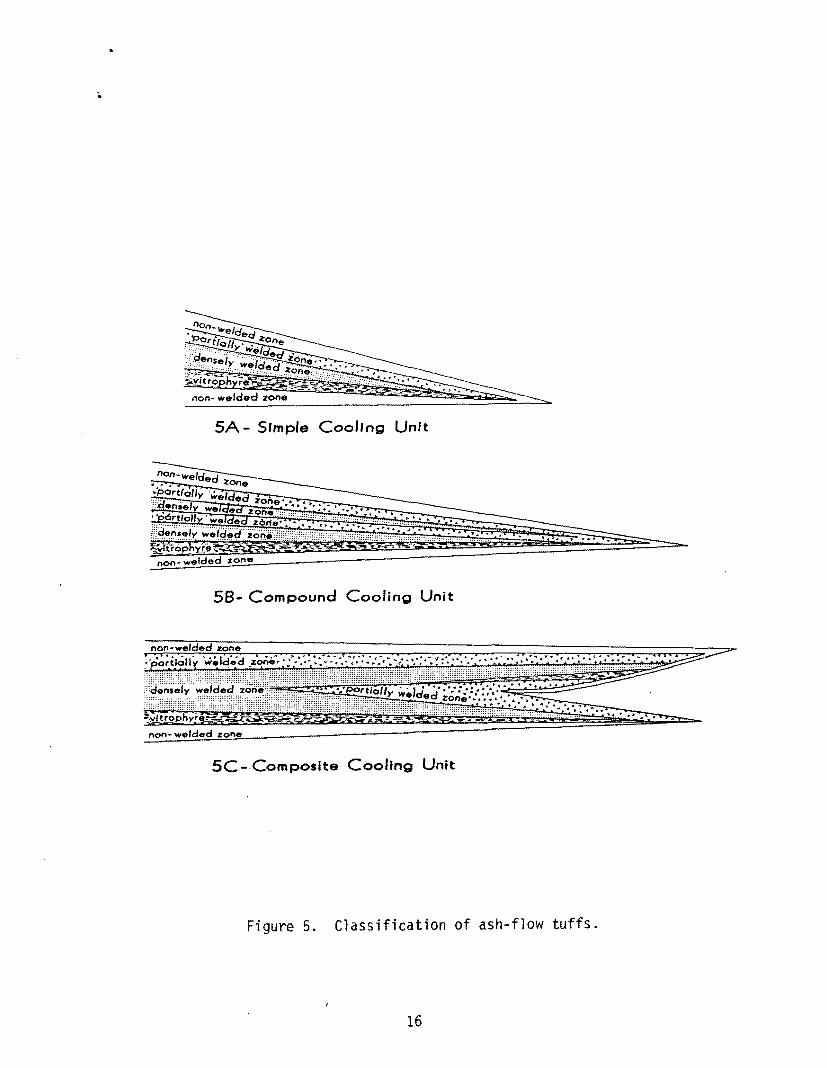
An ash-flow tuff that contains a central densely welded zone and
an upper and lower less-welded zone, as shown in Fig. 5A, is the
prototype of the simple cooling unit. Variations in the initial
conditions discussed above can cause a unit to lack one or more of
these zones.
An ash-flow sheet can consist of several flow units. When these I
flows are closely spaced in time they can conserve heat long enough to
weld as a simple cooling unit. Conversely, when sufficient time
between eruptions is allowed for these tuffs to cool, they will form
separate simple cooling units. Inte~ed;ate between these two cases
is the compound cooling unit, shown in Fig. 58. When the top of a
flow has only time enough to cool slightly before being covered by
15
SA - SImple CoolIng Unft
58- Compound Cooling Unit
5C--Composlte Cooling Unit
Figure 5. Classification of ash-flow tuffs.
16
another ash-flow pulse, a rhythmic alternation of densely welded and
partially welded zones can result. This alternation in an ash-flow
sheet raises its rank to a compound cooling unit.
Ash-flows lose heat in their distal portions due to mixing with
cool air and thinning. While ash-flow pulses may form a compound or
simple cooling unit in the main body of the sheet the distal portions
may have cooled sufficiently to form two or more simple cooling
units. This lateral change in rank defines a composite cooling unit
(F i g. SC).
The source vent of an ash-flow tuff or its proximity to this vent
may be determined in several ways. The first is by recording a change
in rank of the ash-flow tuff in question. Since an ash-flow is
hottest near its source, mapping the transition from a simple to a
compound cooling unit can define a center where the source is likely
to be. Another method is to map intra~caldera vs. outflow rocks (i.e.
Cunningham and Steven, 1977). Intra-caldera rocks are tectonically
chaotic and may include a variety of collapse features. Areally
restricted, thick ash-flow tuffs and tuffaceous sediments are common
to calderas., Domes, lava flows, and shallow intrusives similar in
composition to the ash-flow tuff sheet often define ring dikes formed
by the collapse of a caldera. Outflow rocks are lava flows and
widespread ash-flow tuffs, which thin distally.
17
PRE-TERTIARY STRATIGRAPHY
The only rocks representative of the Paleozoic Erathem at McCoy
are those of the Pennsylvanian and Permian Havallah Formation,
consisting of greenish-grey and dark grey chert, silicified siltstone,
siltstone, calcareous siltstone, and limestone. The Havallah
Formation has not been dated radiometrically or by fossils and was
assigned a Pennsylvanian to Permian age by Stewart et al. (1977)
because of its consistant stratigraphic position below Triassic
strata. Above the Havallah is a tan to red sandstone and siltstone
unit considered by Willden and Speed (1974) to be transitional between
the Paleozoic and Mesozoic systems, referred to in this report as
Permo-Triassic undifferentiated sedimentary rocks. The lithology of
this unit is typical of the Paleozoic strata in this region but is
markedly discordant to bedding of the subjacent Havallah while being
conformable or near conformable with the overlying Triassic
conglomerate.
The Triassic conglomerate is a prominent ledge-former consisting
of red and green chert pebbles in a siliceous matrix. This unit and
the superjacent fossiliferous Faveret Formation are the most easily
recognized of any sedimentary rocks at McCoy. The Faveret Formation
contains dark grey thin-bedded limestones interbedded with black shale
and red to tan siltstones. A Lower Triassic age has been determined
by the presence of abundant ammonites of the genus Acrocordiceras and
18
pelecypods of the genus Daonella (Silberling, 1956). Above this unit
is the Augusta Formation which consists of three members, the lower
two of which are in the mapped area. The lower member is a massive,
dark-grey, bioclastic, dolomitic limestone, and the middle member
includes thin-bedded, grey limestone and calcareous shale. The upper
member is a massive grey limestone (Muller et al., 1951).
19
TERTIARY STRATIGRAPHY
Extrusive Rocks
Dark colored pyroxene-hornblende andesites and dacites form the
oldest Tertiary unit in the vicinity of McCoy. These volcanics rest
unconformably on pre-Tertiary strata and are overlain by rhyolitic
ash-flow' tuffs. Most exposures in the mapped area are propylitically
altered, slope formers, and frequently covered by slope wash. The
base is not exposed and thus the thickness is unknown.
South of McCoy, in the Clan Alpine Mountains, similar flows are
intercalated with epiclastic rocks and vary from a to 800 meters in
thickness (Riehle et al., 1972). These flows have a K-Ar age of 35.9
m.y. which is consistent with the ages of the widespread andesite and
dacite lava flows in Churchill (Willden and Speed, 1974) and Lander
(Stewart et al •• 1977) counties.
An isolated volcanic vent rising 100 meters above pre-Tertiary
sediments lies in the extreme north of the mapped area. It consists
of black lava flows with 40% phenocrysts of plagioclase,
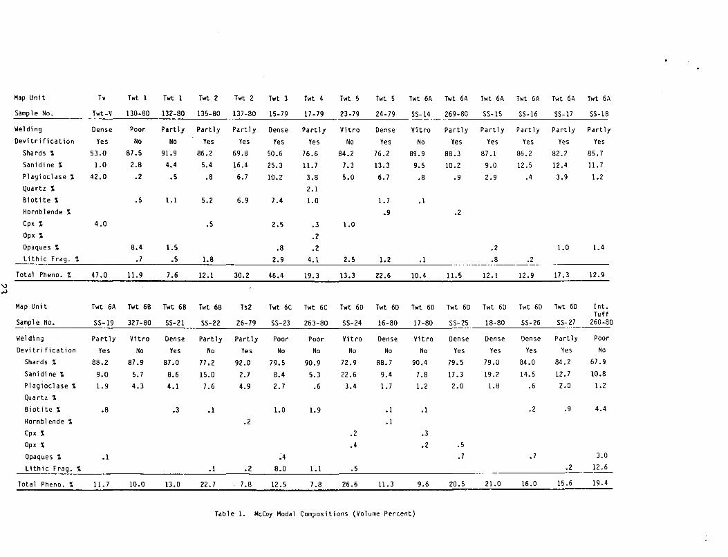
orthopyroxene, and clinopyroxene (see Table 1). The extent of the
flows to the east, north and south is unknown due to the thickness of
the overlying ash-flow tuffs and valley fill and the western margin of
the vent is truncated by faulting and erosion which occurred prior to
the deposition of the fanglomerate. The age of this vent is presumed
to be comparable to the andesites discussed above.
20
Tertiary Fanglomerate
The Tertiary fanglomerate is an informal name first used by Dane
and Ross (1942) to describe an unconsolidated deposit'containing
limestone and cherty dolomite cobbles and boulders which mantle the
pre-Tertiary rocks in the neighborhood of the McCoy and Wild Horse
Mercury Mines. This unit can be recognized by the light color of the
soil matrix as well as the large size (up to 8 meters in diameter) of
the boulders. Its original thickness must have exceeded 75 meters
(Dane and Ross, 1942). The fanglomerate underlies the ash-flow tuffs
in the north-east portion of the mapped area.
Tertiary Ash-Flow Tuffs at McCoy
The formation names used for the ash-flow tuffs in this study are
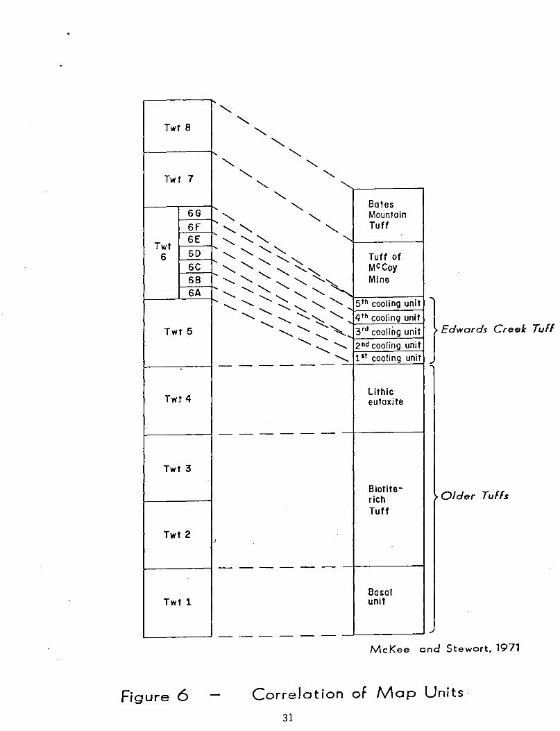
those of McKee and Stewart (1971). The correlation of these units is
shown in Fig. 6. In their report they attempted to systematize the
ash-flow tuffs in the Desetoya Mountains, the New Pass Range, and the
central part of the Shoshone Mountains (Fig. 1) by K-Ar age dating and
regional mapping. The results of their study show that there is
little continuity of formations between the Desetoya Mountains and the
New Pass Range, but that many of the ash-flow tuffs in the New Pass
Range and Shoshone Mountains are correlative and are easily grouped by
mineralogy and extent. The ash-flow tuffs in this study were mapped
by cooling unit. They are designated as Tertiary welled tuffs (Twt)
followed by a number. The tuffs grouped into formations by McKee and
Stewart (1971) have a number as a formation designation and a letter
as a cooling unit designation. For example, Twt 6C denotes the third
cooling unit from the bottom of Edwards Creek Tuff.
The ash-flow tuff stratigraphy used in this study agrees with
21
that of McKee and Stewart (1971) with one exception. Detailed mapping
has shown that several cooling units which do not appear in the type
or reference section of Edwards Creek Tuff are mapped hy McKee and
Stewart (1977) as Edwards Creek Tuff. These cooling units differ in
mineralogy from and are not coestensive with the Edwards Creek Tuff.
The intra-Edwards Creek Tuff units are not large, so rather than
complicate the map by separating them out Edwards Creek Tuff plus the
aforementioned units were mapped as Twt 6.
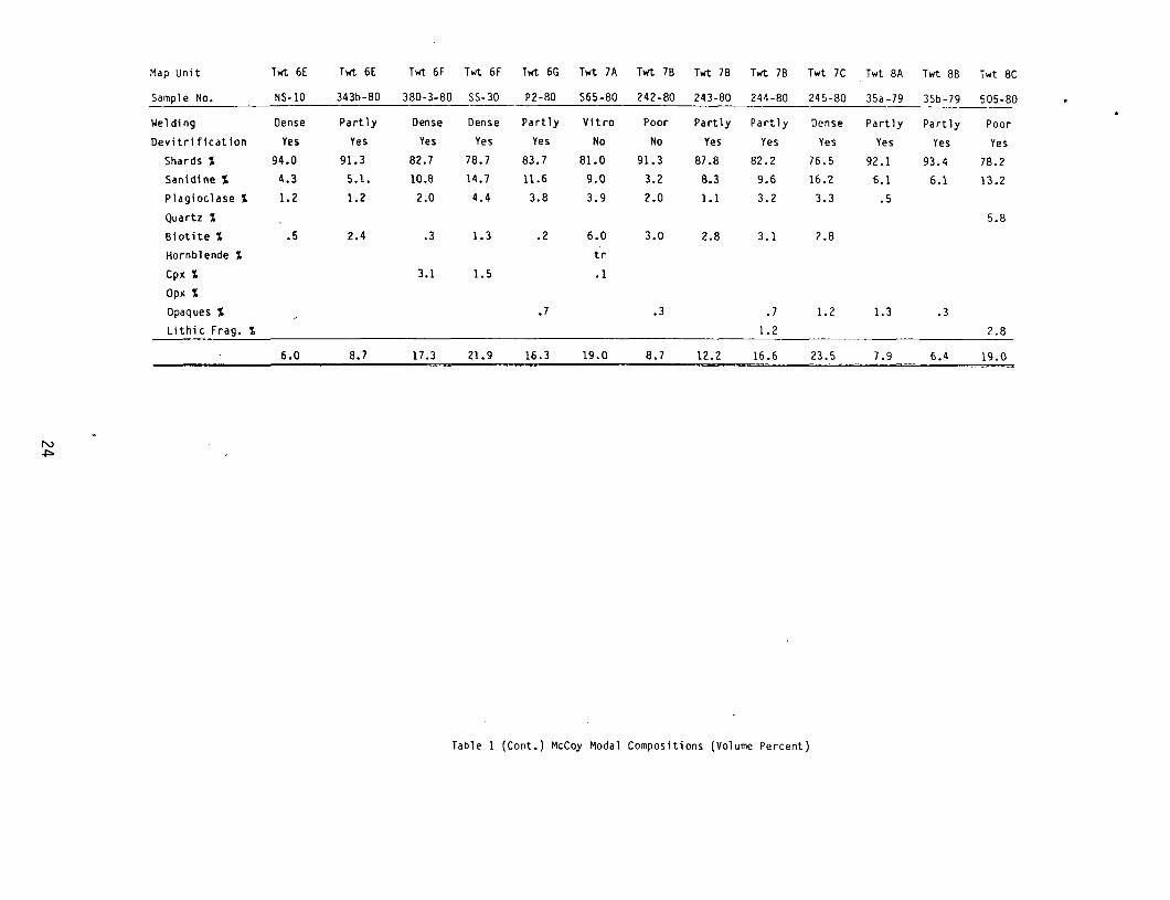
Modal compositions and chemical analysis of each cooling unit are
given in Tables 1 and 2, and the sample locations are shown in Fig. 8.
Older Tuffs
The older ash-flow tuffs, first described by McKee and Stewart
(1971), comprise at least 4 cooling units of ash-flow tuffs which
differ in their mineralogy. In this report they were mapped
separately, and the mapping units Twt 1 to Twt 4 are discussed
individually below.
T~ 1
Twt 1 consists of a simple cooling unit which rests unconformably
on pre-Tertiary sedimentary rocks as well as Tertiary lava flows,
fanglomerate, and an eroded remnant of a poorly welded ash-flow
tuff. The eroded remnant fills a paleo-valley in the cuestas
northeast of the McCoy Mine and is mapped for convenience as together
with Twt 1. This remnant is a grey, vitric, poorly welded ash-flow
tuff with 5 to 10% crystals of sanidine and plagioclase, a trace of
biotite, a few vitrophyric lithic fragments up to .5 cm in diameter,
and some argill;zed flattened pumice fragments approximately 2 cm in
22
Map Unit
Sample No.
Weldin9
Oevitrification
Sha rds ,;
Sanidi ne ,;
Pla9ioclase ,;
Qua rtz ,;
Biotite ,;
Hornblende ,;
Cp~ ,;
Op~ ,;
Opaques ,;
Lithic Fra9. ,;
Total Pheno. ,;
Map Unit
Sample No.
Welding
Oevitri ficat ion
5hards ,;
Sanidine ,;
Pla9ioclase ,;
Qua rtz ,;
Biotite ,;
Hornblende ,;
Cp~ ,;
Tv Twt 1 Twt 1 Twt 2
Twt-V 130-80 132-80 135-80
Dense
Yes
53.0
1.0
42.0
Poor Partly Partly
No No Yes
87.5 91.9 86.2
2.8 4.4 5.4
.2 .5 .8
4.0
47.0
.5
8.4
.7
11.9
1.1
1.5
.5
7.6
Twt 6A Twt 6B Twt 6B
S5-19 327-80 SS-21
Partly Vitro Dense
Yes No Yes
88.2 87.9 87.0
9.0 5.7 8.6
1.9 4.3 4.1
.8 .3
5.2
.5
1.8
12.1
Twt 6B
SS-22
Part ly
No
77 .2
15.0
7.6
.1
Twt 2 Twt 3
137-80 15-79
Pa rt 1 y Oense
Yes Yes
69.8 50.6
16.4 25.3
6.7 10.2
6.9
30.2
7.4
2.5
.8
2.9
46.4
Twt 4
17 -79
Part ly
Yes
76.6
11.7
3.8
2.1
1.0
.3
.2
.2
4.1
19.3
Ts2 Twt 6C Twt 6C
26-79 SS-23 263-80
Partly Poor Poor
Yes No No
92.0 79.5 90.9
2.7 8.4 5.3
4.9 2.7 .6
1.0 1.9
.2
Twt 5
23-79
Vitro
No
84.2
7.3
5.0
1.0
2.5
13.3
Twt 60
SS-24
Vitro
No
72.9
22.6
3.4
Twt 5
24-79
Dense
Yes
76.2
13.3
6.7
1.7
.9
1.2
22.6
Twt 60
16-80
Dense
No
88.7
9.4
1.7
.1
.1
Twt 6A
SS-14
Vi tro
No
89.9
9.5
.8
.1
.1
10.4
Twt 60
17-80
Vitro
No
90.4
7.8
1.2
.1
Twt 6A
269-80
Partly
Yes
88.3
10.2
.9
.2
11.5
Twt 60
SS-25
Dense
Yes
79.5
17.3
2.0
Op~ ,; .5
.2
.4
.3
.2
Twt 6A Twt 6A
SS-15 5S-16
Partly Partly
Yes Yes
87.1 86.2
9.0 12.5
2.9 .4
.2
.8
12.1
Twt 60
18-80
Dense
Yes
79.0
19.2
1.8
.2
12.9
Twt 60
S5-26
Dense
Yes
84.0
14.5
.6
.2
Twt 6A Twt 6A
SS-17 SS-18
Partly Partly
Yes Yes
82.2 85.7
12.4 11.7
3.9 1.2
1.0
17.3
Twt 60
S5-27
Partly
Yes
84.2
12.7
2.0
.9
1.4
12.9
Int. Tuff
260-80
Poor
No
67.9
10.8
1.2
4.4
Opaques'; .1 ;4 .7.7 3.0
__ L~1~·t~h~i~c~F~r~a~9~.~';~ ________________________ ~.~1 ______ ~.2~ __ ~8~.0~ __ ~1~'21 ______ ~.5~ __________________________________________ .2 _____ 12.6
Total Pheno. ,; 11.7 10.0 13.0 22.7 7.8 12.5 7.8 26.6 11.3 9.6 20.5 21.0 16.0 15.6 19.4
Table 1. McCoy Modal Compositions (Volume Percent)
Map Unit Twt 6E Twt 6E Twt 6F Twt 6F Twt 6G Twt 7A Twt 7B Twt 7B Twt 7B Twt 7C Twt 8A Twt 8B Twt 8C
Sample No. NS-I0 343b-80 380-3-80 55-30 P2-80 565-80 242-80 243-80 244-80 245-80 35a -79 35b-79 505-80
Welding Dense Part 1y Dense Dense Pa rt1y Vitro Poor Partly Partly Dense Part 1y Part 1y Poor Devitrification Yes Yes Yes Yes Yes No No Yes Yes Yes Yes Yes Yes
Shards ~ 94.0 91.3 82.7 78.7 83.7 81.0 91.3 87.8 82.2 76.5 92.1 93.4 78.2 Sanidine ~ 4.3 5.1. 10.8 14.7 11.6 9.0 3.2 8.3 9.6 16.2 6.1 6.1 13.2 Plagioclase ~ 1.2 1.2 2.0 4.4 3.8 3.9 2.0 1.1 3.2 3.3 .5
Quartz ~ 5.8
Biotite ~ .5 2.4 .3 1.3 .2 6.0 3.0 2.8 3.1 2.8
Hornblende ~ tr
Cpx ~ 3.1 1.5 .1
Opx ~
Opaques ~ .7 .3 .7 1.2 1.3 .3
Lithic Fra9. ~ 1.2 2.8
6.0 8.7 17.3 21.9 16.3 19.0 8.7 12.2 16.6 23.5 7.9 6.4 19.0
Table 1 (Cont.) McCoy Modal Compositions (Volume Percent)
N U1
Map Unit
5ample No.
Twt 1
Me/NV 132
Twt 2
Me/NV 135
Twt 2
Me/NV 137
Twt 3
Me/NV 15-79
Twt 4
Me/NV 40
Twt 5
Me/NV 23
Twt 5 Twt 611. Twt 611. Twt 6A Twt 6B Twt 6B Ts2 Twt 6C Twt 6D
Me/NV Me/NV Me/NV Me/NV Me/NV Me/NV Me/NV Me/NV Me/NV 24 55-15 269 55-19 55-21 55-22 14-79 38 55-24 •
5i02 68.7 72.6 69.8 66.4 73.0 73.3 74.9 73.9 75.8 73.6 76.0 74.5 70.2 73.1 70.7
Ti02 .13 .14 .31 .42 .15 .13 .24 .15 .14 .19 .22 .28 .20 .20 .23
A1 203 13.1 13.7 14.8 16.1 13.0 14.0 13.8 13.3 13.8 12.7 11.9 12.5 13.8 13.9 14.0
Fe203* 1.79 2.03 2.80 3.28 1.54 1.65 1.23 1.38 1.80 2.04 2.44 2.70 2.59 1.77 1.77
MnO .05 .03 .03 .07 .03 .06 .02 .02 .03 .01 .03 .03 .05 .05 .05·
MgO .44 .51 .48 .76 .84 <.1 <.1 .06 .02 .37 .19 .55 <.1 <.1 .14
CaO 2.30 .72 1.50 2.80 1.53 .71 1.42 .68 .53 .97 1.02 1.74 .99 1.02 .80
Na 20 3.19 2.61 3.51 3.52 2.41 3.15 3.59 3.77 3.54 3.31 3.12 3.08 2.75 2.67 2.98
K20 5.09 5.69 5.22 4.91 4.70 6.02 4.68 5.42 5.62 5.08 4.56 4.33 6.32 6.21 6.24
P205 .04 .03 .07 .11 .06 .01 .06 .01 .03 .02 .03 .08 .05 .02 .00
-,:L.::O:..I _______ 5:;.~3.:.9 __ 2:::.:.:1.:.0 __ =_1.:.:3...::5 __ 2=_ • ...::8.:.9 __ 4._: • ...::5.:.5 __ =_3 .=-0_7 __ -=-1....::1...::8 __ -=-1....::0...::0 ___ 1....::1.:.2 __ .:.2=-. 3_0 __ .:.2:...:.1...::0 __ .:.2 • ...::3...::0 __ =_3.:..:.7...:1 __ .:.1:...:.5:..:.7 __ .:.3:;.8:.:.0 ,,'
Total
CI PW Nonns
Q C
or
ab
an
ac
wo
di-wo
di-en
hy-en
mt
11
hm
tn
ru
ap
Total
100.2
25.83
30.08
26.99
6.48
.58
1.27
1.10
.11
1.79
.18
.07
94.49
100.12
33.32
1.91
33.62
22.08
3.38
1.27
.06
2.03
1.11
.07
97.86
99.85 101.32 101.74 101.96 101.04
25.63
.85
30.85
29.70
6.98
1.20
.06
2.80
.28
.17
98.51
20.34
.18
29.01
29.79
13.17
1.89
.15
3.28
.34
.26
98.41
36.58
1. 27
27.77
20.39
7.20
2.09
.06
1.54
.12
.14
97.17
30.44
1.07
35.57
26.65
3.46
.13
1.65
.06
.02
99.06
33.19
.40
27.66
30.38
6.65
.04
1. 23
.22
.14
99.91
99.70 102.35 100.63 101.65 102.10 100.64 100.52
29.74
.01
32.03
31. 90
3.31
.15
.04
1.38
32.60
.95
33.21
29.95
2.43
.05
.06
1.80
.13 .11
.02 .07
98.71 101. 24
32.34
.06
30.02
28.01
4.68
.92
.02
2.04
.18
.05
98.32
38.05
.05
26.95
26.40
4.86
.47
.06
2.44
.19
.07
99.55
35.85
25.59
26.06
7.44
1. 37
.06
2.70
.47
.05
.19
99.79
28.01
.79
37.35
23.27
4.58
.11
2.59
.14
.12
96.96
31.68
.98
36.70
22.59
4.93
.11
1.77
.14
.05
98.95
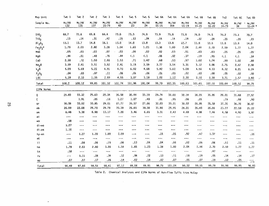
Table 2. Chemical Analyses and CIPW Norms of Ash-Flow Tuffs from McCoy
99.75
27.57
.90
36.87
25.22
3.97
.35
.11
1.77
.17
96.93
Map Unit TI'it 60 TI'it 60 TI'it 6E TI'it 6E TI'it 6F Twt 6F TI'it 7C Twt- 8A
Sample No. Me/NY Me/NY Me/NY Me/NY Me/NY Me/NY Me/NY Me/NY 18-80 SS-26 NS-10 380-3 343b-80 55-30 245 228
5i02 72.6 71.7 74.0 76.3 77.9 73.5 71.3 75.0
Ti02 .22 .25 .12 .10 .09 .18 .39 .08 A1 203 14.8 14.2 11.9 13.0 11.6 13.8 15.9 12.9
Fe203* 2.09 2.19 1.60 1. 71 1.50 2.16 2.21 1.13 MnO .04 .03 .04 .07 .08 .03 .06 .08 MgO .01 .21 .17 <.1 <.1 .13 .28 .01 CaO .82. .92 .58 .30 .39 .62 1.69 .46
Na20 3.77 3.75 4.06 4.04 3.57 4.45 4.20 3.32 K20 5.47 5.63 4.92 4.88 4.29 5.08 4.71 5.09 P205 .01 .02 .01 .02 .01 .01 .06 .00
LOl .71 1.30 2.30 1.07 1.65 1.00 1.48 3.00
Total 100.44 100.29 99.66 101. 23 100.88 100.98 102.30 101.04
CIPW Norms
Q 27.94 26.03 30.80 33.50 39.90 26.77 24.96 35.17
C 1.17 .31 .53 .39 .99 1.09 N 0'1 or 32.32 33.27 29.07 28.84 25.35 30.02 27.83 30.08
ab 31.90 31.90 33.77 34.19 30.21 37.65 35.54 28.09
an 4.00 4.43 1.36 1.87 2.68 7.99 2.28
ae .52
wo .58
di-wo .49
di -en .42
hy-en .02 .52 .32 .70 .02
mt .03
i1 .09 .06 .09 .15 .17 .06 .13 .15
hm 2.09 2.19 1.42 1.71 1.50 2.16 .21 .11
tn .18 .23
ru .17 .22 .02 .05 .32
ap .02 .05 .02 .05 .02 .02 .14
Total 99.74 98.99 97.37 100.35 99.42 99.98 100.82 98.04
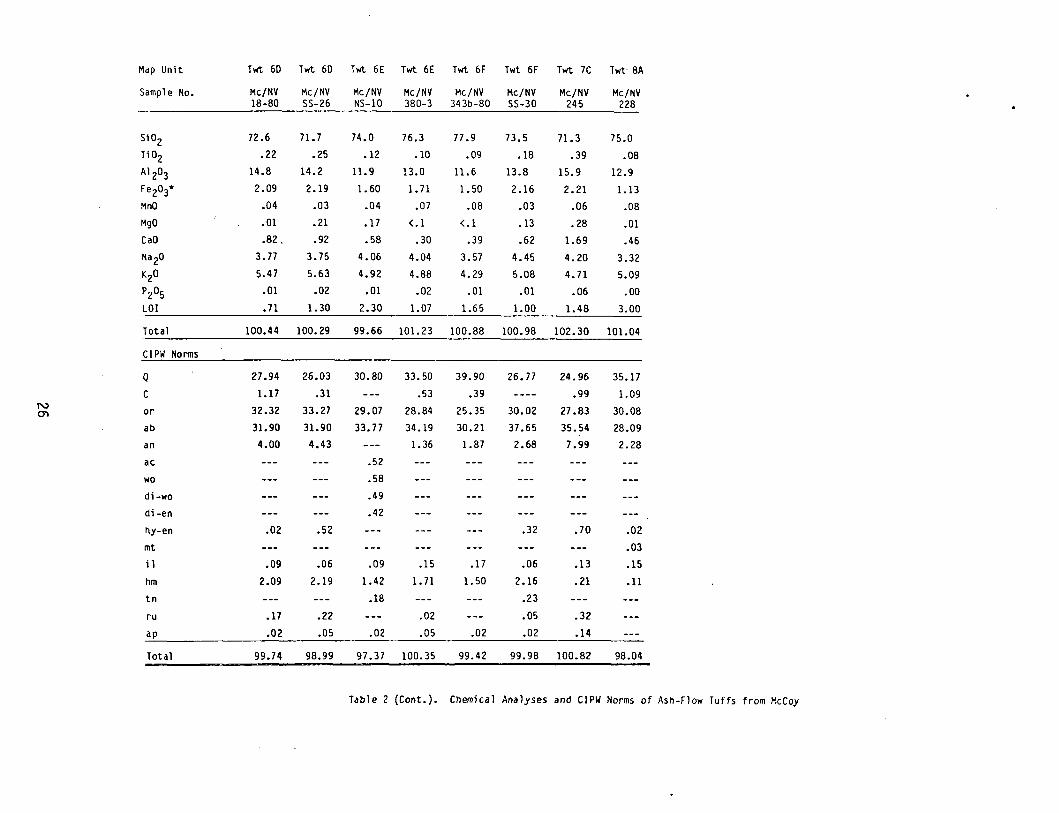
Table 2 (Cont.). Chemical Analyses and CIPW Norms of Ash-Flow Tuffs from McCoy
length.
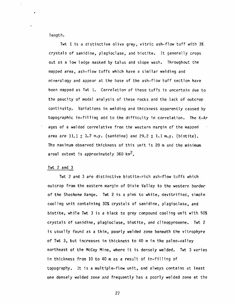
Twt 1 is a distinctive olive grey, vitric ash-flow tuff with 3%
crystals of sanidine, plagioclase, and biotite. It generally crops
out as a low ledge masked by talus and slope wash. Throughout the
mapped area, ash-flow tuffs which have a similar welding and
mineralogy and appear at the base of the ash-flow tuff section have
been mapped as Twt 1. Correlation of these tuffs is uncertain due to
the paucity of modal analysis of these rocks and the ·lack of outcrop
continuity. Variations in welding and thickness apparently caused by
topographic in-filling add to the difficulty in correlation. The K-Ar
ages of a welded correlative from the western margin of the mapped
area are 31.1 ± 1.2 m.y. (sanidine) and 29.2 ± 1.1 m.y. (biotite).
The maximum observed thickness of this unit is 20 m and the minimum
areal extent is approximately 360 km 2•
Twt 2 and 3
Twt 2 and 3 are distinctive biotite-rich ash-flow tuffs which
outcrop from the eastern margin of Dixie Valley to the western border
of the Shoshone Range. Twt 2 is a pink to white, devitrified, simple
cooling unit containing 30% crystals of sanidine, plagioclase, and
biotite, while Twt 3 is a black to grey compound cooling unit with 50%
crystals of sanidine, plagioclase, biotite, and clinopyroxene. Twt 2
is usually found as a thin, poorly welded zone beneath the vitrophyre
of Twt 3, but increases in thickness to 40 m in the paleo-valley
northeast of the McCoy Mine, where it is densely welded. Twt 3 varies
in thickness from 10 to 40 m as a result of in-filling of
topography. It is a multiple-flow unit, and always contains at least
one densely welded zone and frequently has a poorly welded zone at the
27
top and bottom (see Fig. 6). Twt 3 has a K-Ar age of 28.7 + 1.1 m.y.
(McKee and Stewart, 1971).
Twt 4
Twt 4, called lithic eutaxite by McKee and Stewart (1971), is a
distinctive, quartz-bearing, compound cooling unit. It contains up to
20% crystals of sanidine, plagioclase, quartz, and biotite, with
abundant pumice fragments and small scattered black and red lithic
fragments of shale. This unit has two outstanding features; 1) the
densely welded zone is a classic example of a eutaxite, with numerous
black glass fiamme (a flame-shaped welded pumice) up to 10 cm in
diameter, and 2) ~he shards of the poorly welded zone are frequently
altered to zeolites and clays, giving these zones a distinctive waxy
luster with a red to green tint. The green tint is especially
pronounced in areas of hydrothermal alteration. Twt 4 is
characteristically associated with opal-cemented breccia in fault
zones where breccia occurs. The non-welded top of Twt 4 is usually
preserved, above which lenticular beds of sediment and air fall tuff
(Tsl) occur. The thickness of Twt 4 varies from 125 m in Shoshone
Canyon to 60 m at the western edge of Antelope Valley, a distance of
35 km. Twt 4 most often overlies Twt 3, but at a few localities lies
unconformably on pre-Tertiary strata. The minimal areal extent of Twt
4 is approximately 360 km2•
28
Northern Ash-Flow Tuffs (Twt 5)
Along the northeast margin of the mapped area are two cooling
units of ash-flow tuff mapped by McKee and Stewart (1971) as Edwards
Creek Tuff. Although they lie in the same stratigraphic position as
the lower units of Edward Creek they differ in mineralogy, cooling
history, and distribution.
The lower unit of the northern ash-flow tuffs is a vitrophyre
containing 25% crystals of sanidine, plagioclase, biotite, and
hornblende. Overlying the vitrophyre with no discernible cooling
break is the middle unit, consisting of a red, densely welded
devitrified zone and containing 13% crystals of sanidine, plagioclase,
and clinopyroxene. The upper unit is a lavender, partially welded
ash-flow tuff with 20% crystals of sanidine, biotite, and plagioclase,
with white slightly flattened pumice up to 30 cm in length and
abundant lithic fragments of densely welded ash-flow tuff up to 15 cm
in diameter. The cooling relationship of the upper and middle units
is obscured by the slope-forming nature of the upper unit.
The total observed thickness of these units is 55 m with an areal
extent of 90 km 2•
Edwards Creek Tuff (and Interfingering Tuff)
The Edwards Creek Tuff, defined by McKee and Stewart (1971)
consists of 5 cooling units of similar mineralogy. Although the
description of these tuffs conforms to those found in the type
section, several cooling units mapped as Edwards Creek do not appear
in the type section, located 19 km south of the McCoy Mine.
Three of these cooling units were mapped as Twt 5, as mentioned
above. One unit, Twt 6C, that consistently lies below the third
29
cooling unit of McKee and Stewart (1971) in the mapped area and was
grouped with Edwards Creek in the Twt 6 series, does not appear in the
type or reference section (Fig. 6). Twt 6G, an areally restricted
unit sitting on the fifth cooling unit of McKee and Stewart (1971) is
also missing in the type and reference sections. This unit was also
included with Twt 6.
The observed thickness of Twt 6 varies from 190 m in the south to
110 m in the northeast corner of the mapped area (Fig~ 7a,b). This is
due to the disappearance of Twt 6A in the northern area rather than
the distance of Twt 6 from its source area.
McKee and Stewart (1971) published an average K-Ar age for the
third and fourth cooling units of Edwards Creek Tuff (Twt 60 and 6E)
as 27.7 + 1 m.y.
Twt 6A
Twt 6A is the oldest cooling unit of the Edwards Creek Tuff.
Within the mapped area it is grey to pale red, partially welded, and
contains 19% crystals of plagioclase and sanidine, and a trace of
hornblende. It is a multiple ash-flow simple cooling unit, the lower
ash-flow being eutaxitic with white flattened pumice up to 10 cm in
length while the upper flow is structureless. The basal vitrophyre is
frequently covered and probably lenticular. Twt 6A is poorly welded
10 km west of the unit area, in the Shoshone Range. Twt 6A lies
unconformably above Twt 4, separated from it by variable thicknesses
of air-fall tuff and tuffaceous sediment (Ts1).
The minimum areal extent of Twt 6A is 360 km 2• It extends from
the Shoshone Range to the eastern edge of Dixie Valley and at least as
far south as the type section of McKee and Stewart (1971). It does
30
r-
Twt 8
,..
Twt 7
6G .....
6F .....
6E "-
Twt .....
6 60 "-
6C 68 6A "'"
"'"
Twt 5
Twt4
Twt 3
Twt 2 I
Twt 1
Figure 6
Bates Mountain Tuff
........
Tuff of MCCoy Mine
"'-.... 5 th cooling unit
,4th cooling unit
.... 3 rd cooling unit Edwards Creek TuFF
........... 2nd cooling unit ............ 1st cooling unit
Lithic eutaxite
Biotife-rich Older Tuffs Tuff
Basal unit
. McKee end Stewart. 1971
Correlation of Map Units
31
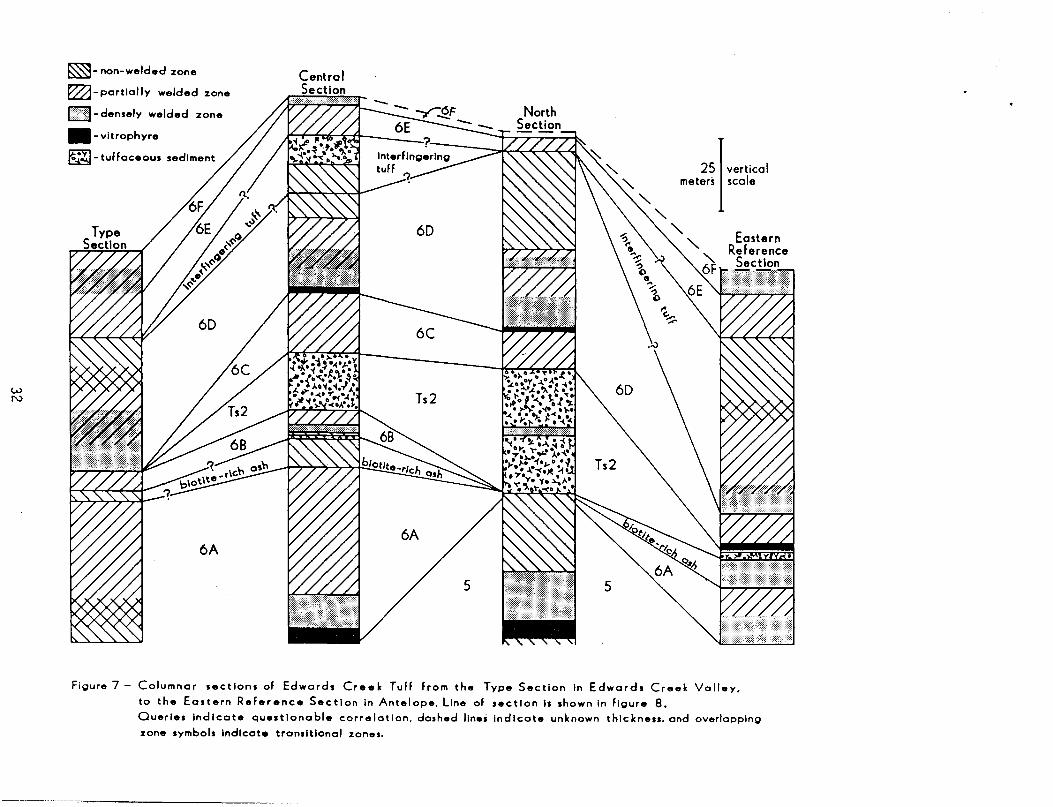
W N
~- non-welded zone
~ - partia"y welded zone
I mimI -densely welded
• - vitrophyre
I#:!I- tuffaceous
zone
25 I vertical meters scale
Figure 7 - Columnar sections of Edwards Creek Tuff From the Type Section In Edwards Creek Valley,
to the Eastern ReFerence Section in Antelope. line of ,ectlon Is shown In Figure S.
Queries IndIcate questIonable correlation. dashed lines IndIcate unknown thickness. and overlapping
zone symbols IndIcate transItIonal zones.
118°00' 117°00' 40000' 40°00'
\O?e f>-.{\te \]a\ \e~
~
~\e~ .~ "'Tl !:J ~. ~O I.C § c
<;j\i\e '"1
~ Cl)
-....,J 0-
~ .~~ r ~ 0 ~~ q) (")
~Oy><S (g Q.I rt
~ .~ ~.
~ 0 ~ ::l e w 0 ~\~ ~
§ w -+.
V ~ (")
~ 0 ....... Q) c \}O~ ~ 3 ~
::l ~ Q.I '"1
...... 6' VI
Cl) E.::: (")
rt ~.
0 ::l VI
40°30'
5 0 5MI Iii I , , i
not extend into the northeast portion of the mapped area, because of
faulting in the mine area that produced topographic barriers.
Twt 68
The most distinctive marker horizon of Twt 6 is Twt 68, the
second cooling unit of McKee and Stewart (1971). This brick red,
densely welded, structureless, compound cooling unit contains less
than 10% crystals of sanidine and plagioclase, and a trace of
biotite. It consists of lenticular basal non-welded and vitrophyre
zones, a ledge-forming densely welded devitrified zone, and upper
partially welded and non-welded zones which are frequently
preserved. Within the mapped area the densely welded zone shows no
cooling breaks but several kilometers to the south the flow partings
allow no doubt of its status as a compound cooling unit.
Twt 68 was found by McKee and Stewart (1971) in their reference
section near Antelope Valley, although this unit was not located at
that site during the present study. It was not found near Dixie
Valley or in the northeast corner of the mapped area. Its minimum
areal extent is 100 km2• The observed thickness is about 10 m.
Ts2
The thickest accumulation of tuffaceous sediment (Ts2) in the
McCoy area consistently occurs below Twt 6C. This sediment has cross
bedded to planar bedding and is crystal-rich. Ts2 is lenticular due
to erosion prior to the deposition of 6C, with a thickness varying
from a to 10 m. In a few localities Twt 6C either failed to surmount
the topography of the tuffaceous sediments or was eroded, in these
areas Twt 60 directly overlies the sediment.
34
North of the McCoy mine, where Twt 6B is absent, the tuffaceous
sediment is significantly thicker (40 m) and lies on the upper unit of
Twt 5. Here the sediment is more pumice-rich, crystal-poor, and
interbedded with a thin, red, densely welded ash-flow tuff containing
less than 10% crystals of plagioclase and sanidine and a trace of
hornblende.
Twt 6C'
Another good marker horizon in the mapped area is Twt 6C.
Although frequently covered with slope wash, its mineralogy, large
frothy pumice, and large lithic fragments readily distinguish this
unit from the rest of Edwards Creek Tuff. Twt 6C is a light brown to
green, friable, partially welded ash-flow tuff. It is a partially
welded cooling unit consisting of 8% crystals of sanidine, biotite,
and plagioclase, and it contain~ large white pumice up to 30 cm in
length, black vitrophyre lithic fragments up to 10 cm across, and
vapor phase minerals. In a few places Twt 6C is pink, densely welded,
and loses its distinctive friable texture and the frothy nature of its
pumice. Twt 6C has a minimu~ areal extent of 91 km 2 and a maximum
observed thickness of 20 meters.
Twt 60
Twt, 60 is a canpound cool i ng unit canposed of at 1 east 3
distinctive flow units. The basal portion is grey, per1itic, densely
welded, and contains 11% crystals of sanidine, plagioclase, and a /
trace of biotite and hornblende. This unit is 2 m thick and can be
distinguished by its yellow-orange stained fractures. Above this is a
23 m thick structure1ess, red, partially to densely welded flow unit
35
with a severely weathered basal v;trophyre. This unit contains 9%
crystals of sanidine and plagioclase as well as .5% crystals of
clinopyroxene, orthopyroxene, and biotite. The upper unit has similar
mineralogy but contains up to 1% biotite. It is partially welded,
eutaxitic, and large cavities have formed from weathering. Twt 60 has
an observed thickness of 50 meters where the non-welded top is
preserved, and a minimum areal extent of 360 km 2• Twt 60 is the
equivalent of McKee and Stewarts (1971) third cooling unit of Edwards
Creek Tuff which was dated by them, using the K-Ar method, at 27.6 ± 1
m.y.
Interfingering Ash-Flow Tuff
Interfingering with Edwards Creek Tuff is a lavender to purple
ash-flow tuff containing 26% crystals of sanidine, plagioclase,
biotite, and moderately abundant lithics of densely welded ash-flow
tuff. Within the reference section of Edwards Creek (McKee and
Stewart, 1971) this unit is 70 m thick and lies between Twt 60 and 6E
with no discernible cooling break. The distal portion of this unit
extends into the mapped area in one locality and is represented by a
10 m thick partially welded ZOne overlain by 10 m of epiclastic
sed; ments.
Twt 6E
Twt 6E, the fourth cooling unit of Edwards Creek Tuff (McKee and
Stewart, 1971), is an easily recognizable horizon in the Twt 6
series. Usually occurring as a low cliff, this light purple,
partially welded ash-flow tuff contains 8% crystals of sanidine,
plagioclase, and biotite. In most places it is 10 m thick, but where
36
it lies below Twt 6G it doubles in thickness and is densely welded.
Twt 6E has a minimum areal extent of 160 km 2 and a K-Ar age of 27.7 ±
1 m.y. (McKee and Stewart, 1971).
Twt 6F
Twt 6F ;s a simple cooling unit. Cooling relationships within
this unit are poorly defined due to poor outcrop. It is a red to grey
ash-flow tuff with a densely and a partially welded zone that contains
13% crystals of sanidine and plagioclase. The partially welded vapor
phase zone is eutaxitic and contains up to 1% biotite. The minimum
areal extent of this unit is 160 km 2, the maximum observed thickness
is 20 m.
Twt 6G
This unit is purple, densely welded, and contains 17% crystals of
sanidine, plagioclase, and quartz, with an observed thickness of 15
m. It outcrops in a 3 km2 area 1 km south of the Wild Horse Mine.
Most of the details of Twt 6G are obscured by talus and faulting.
Tuff of McCoy Mine
The Tuff of McCoy Mine was infonnal,ly designated as such by McKee
and Stewart {1971} because of its numerous outcrops just south of
McCoy Mine. Generally occurring as a soft slope capped by its upper
densely welded unit (7C) and Bates Mountain Tuff, the Tuff of the
McCoy Mine consists of at least four cooling units. The most notable
aspects of this tuff are the consistent presence of biotite and the
brittleness of the poorly welded zones. Brittleness in poorly welded
ash-flow tuffs is attributed by Smith (1960) to induration by vapor
phase minerals. The minimum thickness and age are, respectively, 60 m
37
and 27.0 ± .9 m.y. (McKee and Stewart, 1971).
Twt 7A
Twt 7A consists of at least 2 cooling units. The lower is a
white, poorly welded, crystal-poor ash-flow tuff containing sanidine,
biotite, plagioclase, and a few small pumice and lithic fragments.
The maximum thickness of this unit is 23 m.
The upper cooling unit is a lenticular vitrophyre containing 18%
crystals of sanidine, biotite, and plagioclase. This unit consists of
30 cm of non-welded ash at the lower contact and is platy, vitric, and
poorly welded near the upper contact. Therefore it is considered to
be a simple cooling unit.
Twt 7B
The middle unit of the Tuff of McCoy Mine is a multiple-ash-flow
simple cooling unit. It consists of several partially welded zones
separated by flow breaks or less welded zones that manifest themselves
as ledges and partings. It is grey, orange, or pale purple and
contains 14% crystals of sanidine, biotite, and plagioclase as well as
a few scattered pumice and lithic fragments. The case-hardened aspect
is especially evident in this unit. Its thickness is at least 50 m.
Twt 7C
The dense welding and abundant biotite of Twt 7C makes it the
best marker horizon of the upper ash~flow tuffs in the McCoy area. It
is consistently red, structureless, densely welded, and contains 22%
crystals of sanidine, biotite, and plagioclase. The observed
thickness is 5 m.
38
Bates Mountain Tuff
The Bates Mountain Tuff was defined by Stewart and McKee (1968)
at Bates Mountain in western lander County. It consists of 5 cooling
units with a total thickness of a few hundred meters. It has an areal
extent of 5600 km 2 and is found in Nye, Lander, and Churchill Counties
(Stewart et al., 1977).
The units of Bates Mountain Tuff present in the McCoy area are
mapped as Twt BA, 88, and 8C, and correlate with units 1, 4, and
possibly 5 of Sargent and McKee (1969). In the map area Bates
Mountain Tuff can be recognized on aerial photographs because of the
development of dendritic drainage patterns on dip slopes. Scarp
slopes of Bates Mountain Tuff generally develop fewer cliff exposures
than the other tuff units. The average age of the five Bates Mountain
cooling units ;s 24.6 m.y. (Stewart et al., 1977).
Twt 8A
Twt 8A is a 46 m thick slightly eutaxitic compound cooling unit
correlable in lithology, age, and chemistry to unit 1 of Sargent and
McKee (1969). It consists of two partially welded zones separated by
a flow break ledge and a basal vitrophyre. This unit is pale pink to
red and contains less than 10% crystals of sanidine and plagioclase.
All exposures of the lower vitrophyre exhibit secondary
devitrification. The basal portion of both flows fonn low rounded
cliffs, while the partially welded zones are slope fonners. The K-Ar
age of this unit is 25.3 ± 1.0 m.y. in the Shoshone Mountains (McKee
and Stewart, 1971) and 24.7 ± 1.0 m.y. in the Simpson Park Mountains
(Naeser and McKee, 1970). The observed thickness in the McCoy area is
50 m.
39
Twt 8B
The basal zone of Twt 8B is the most distinctive horizon of the
Bates Mountain Tuff. It consists of aIm thick, red, densely welded
zone with spherical cavities about 1 cm in diameter and contains less
than 7% crystals of sanidine and plagioclase. This is the "swiss
cheese ll horizon of McKee and Stewart (1971) and unit 4 of Sargent and
McKee (1969). A 2 m thick, pale red, eutaxitic, densely welded zone
overlies the swiss cheese horizon and west of the McCoy Mine is in
turn overlain by an 8 m thick, soft grey, partially welded, eutaxitic
zone with vapor phase crystallization. The K-Ar age of the basal unit
of Twt 8B is 23.9 ± .9 m.y. (McKee and Stewart, 1971). The total
observed thickness of these units is 25 m.
Twt 8C
Twt 8C is another distinctive horizon in the Bates Mountain Tuff.
It is a pink to grey, partially to poorly welded simple cooling unit
containing 19% crystals of sanidine and quartz. This unit was dated
by McKee and Stewart (1971) at 24.2 ± .9 m.y. Twt 8C is confined to
one ridge 2 km north of Hole-in-the-Wall Well, where it ;s 10 m thick.
40
QUATERNARY ALLUVIUM
There appears to be more than one period of alluvium development
in the study area. Several mounds of coarse alluvium up to 15 m in
height occur near Hole-In-The-Wall Well #2. Alluvium is presently
accumulating in valleys, and is locally overlain by or interbedded
with calcareous travertine.
41
COMPOSITION AND CLASSIFICATION OF ASH-FLOW TUFFS
The chemical compositions of the ash-flow tuffs at McCoy were
determined by X-ray fluorescence, flame photometry, and inductively
coupled plasma spectrometry (ICP). Table 2 lists the major element
contents of 24 samples and their respective norms. Sample locations
are shown in Figure 8.
The silica values range from 66 to 78%. The lower end of this
range, 66-72% characterizes the oldest ash-flow tuffs, Twt 60, and the
Tuff of McCoy Mine. The upper range of values, 73-78%, is comprised
of Twt 4, 5, 6A-C, 6E-G, and Bates Mountain Tuff. All of the samples
contain normative quartz, orthoclase, albite, anorthite, ilmenite, and
hematite. A majority have normative corundum, hypersthene, rutile,
and apatite. No modal topaz or muscovite were observed. Only a few
contain normative titanite or acmite. Of the 3 rocks that do not have
normative corundum, two contain normative wollastonite and diopside.
Compositional variations within a single cooling unit can be
related to several processes, and the samples for analysiS must be
chosen accordingly. Several primary and secondary causes of chemical
variation must be taken into account.
Primary zonation produces compositional zonation from high silica
content at the base of the unit to a lower silica content at the
top. The classic example of primary zonation is the Bishop Tuff
(Hildreth, 1979). In order to detect compositional zonation at least
42
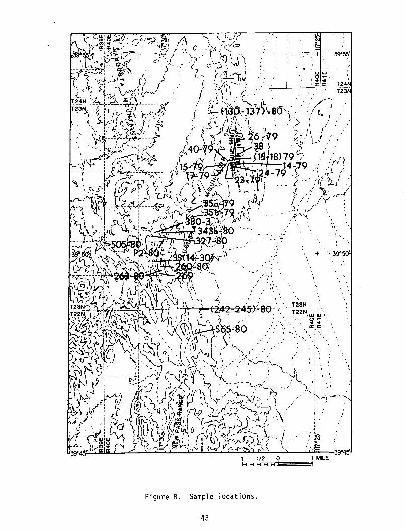
Figure 8.
"
, '
~I~--·+·--~~-;-:-I r
(
r I
" "I , 1ft
I \
( (
I :C"~ I Q
\
I
I I
.- _____ :::11
Sample locations.
43
II I (
II (
\ I ,
\ \
, I
+
J
r I
I J
, , I'
, \
\
I I I
, \
/
\ I I
I
,
,
I
I
/
I
,
,
,
/ (
, , \
\
, \
, I
I J
two widely-spaced (vertically) samples were analyzed for most of the
cooling units. Only one unit, Twt 2, shows this type of zonation.
Post-emplacement alteration consists of deuteric alkali exchange
in feldspars (Scott, 1971a, b), hydration, secondary crystallization,
primary crystallization, and ground-water alteration (Lipman, 1967;
Lipman et al., 1969; Noble et al., 1967; Rosholt and Noble, 1969;
Rosholt et al., 1971). The effects of hydration and secondary
crystallization may be minimized by taking samples tryat have undergone
primary crystallization. The extent of deuteric and ground-water
alteration is dependent on the shard surface area and permeability,
and thus may be minimized by choosing a densely welded sample.
Of the analyses in Table 2, several were vitrophyres and a few
were partially welded. The partially welded samples were analyzed for
comparison or when a densely welded, devitrified zone was lacking in
the cooling unit. The state of welding and the presence or absence of
devitrification for each of the analyses can be found in Table 1.
The ash-flow tuffs in the McCoy area were classified by plotting
the normative feldspars on a ternary diagram (O'Connor, 1965). As
shown in Figure 9, all units plot in the rhyolitic field except Twt 3,
which plots as a quartz latite. The presence of normative corundum
and lack of subequal Na 20 and K20 indicate that these rhyolites are
closest in composition to the average calc-alkaline rhyolite of
Nockolds (1954).
44
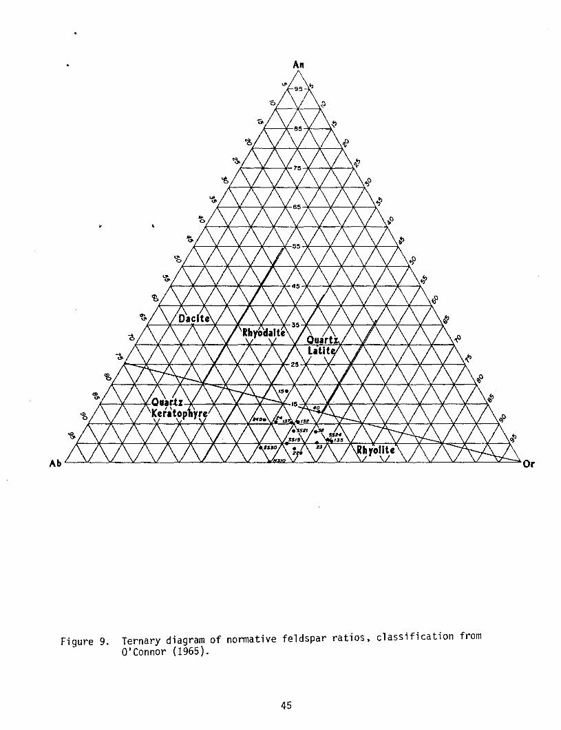
Figure 9.
An
Ternary diagram of normative feldspar ratios, classification from O'Connor (1965).
45
STRUCTURE
Paleozoic Structure
The earliest of the two Paleozoic structural events likely to
have affected this area is the Roberts Mountain thrust of probable
Early Mississippian age (Gilluly and Gates, 1965). This thrust fault
emplaced early Paleozoic siliceous sedimentary rocks over carbonate
facies of comparable age. This thrust, if present in the McCoy area,
must lie at considerable depth since the youngest rocks encountered in
the 800 m drill hole were of Pennsylvanian age.
The second Paleozoic event is the Sonoman Orogeny of Late
Paleozoic age. During this event the Havallah Formation was tightly
folded and thrust eastward. Its basal contact is not exposed at McCoy
but elsewhere it has been mapped consistently in thrust contact with
the underlying rocks (Silberling and Roberts, 1962).
Mesozoic Structure
The only Mesozoic rocks present in the area mapped are those of
the Triassic Augusta Sequence. This carbonate assemblage was folded
during Jurassic or Cretaceous time (inferred from flat-lying Tertiary
strata) into nearly orthogonal fold sets whose mean axial traces are
northwest and southwest (Willden and Speed, 1974). The southwest
trending folds are broader and younger than those trending
northwest. In the New Pass Range, Permian and Triassic rocks are
folded in an anticline whose axis plunges 42°W, and whose axial
46
surface dips 700N (Willden and Speed, 1974).
Tertiary Structures
Little is known about pre-Basin and Range Tertiary structure in
this area due to a depositional hiatus that lasted from Late Triassic
to middle Tertiary time. The existence of thick Tertiary fanglomerate
north of the mercury mines as well as the distribution of Twt 6A and
68 implies some significant structural activity prior to rhyolite
volcanism, but these structures are largely covered. The structure or
series of structures responsible for the erosion and deposition of the
fanglomerate are apparently restricted to the area north of the Wild
Horse Mine, although there was some subsidence 1 km south of the mine
between the emplacement of Twt 6D and 6E.
The maximum age of Basin and Range faulting is 23 m.y., the age
of the youngest ash-flow tuff. Ash-flow tuff zonation is an excellent
indicator of fault scarps formed during or previous to emplacement.
The tuffs of McCoy Mine and Bates Mountain were deposited in the McCoy
area on very low topography, with little disruption from fault
scarps. The minimum age of Basin and Range structures is not
definable in the McCoy area, but the 15 m.y. old basalts in the Clan
Alpine Mountains cover Basin and Range faults and are thus younger
(Riehle et al., 1972).
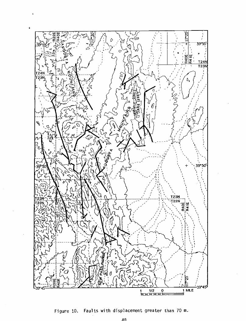
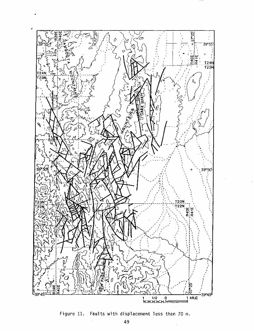
Basin and Range faults vary in displacement from 5 to 500 meters
and strike east-northeast to west-northwest, giving rise to a
polygonal pattern. Faults of major displacement (Fig. 10, 11) trend
northeast or northwest but due to splaying they commonly follow a
rather angular path. There is no significantly predominant sense of
faulting. Some of these structures have variable displacement along
47
\
\
Figure 10.
" 10 " N
I , " ~ , , ,
" 39°55' , , , I
" I' ,
, , .. I ,
)I I , , WW·
r r
, , ,
" 'I , IA
.... -----':::'ll II
" I I I' 11/
/ -r I I
I I I \ • ( I
, ,
\
I
I
, I
I
I \
\ \
0 ~
'0:
\ \
,
+
Faults with displacement greater than 70 m.
l'lA
..- \ ~, 0:. T24
\
,
I I I
T23
• , "
\ I
I
" , , , ' \ ' I , \
, " !
I
, 39°50' ! , ,
I I
I \
, \
\ \ \ ,
I \
I , \
\ , \
, \
\
\ \ 1 ,
\
I I
)
I I I I I
•
\
I
Fi gure 11.
" 'I , , ,
,t
" I, , I
I \
/
1 /
/
\ I
" /
1 1/2 0 B El ~B 1::11
I
\
I
I /
I
I
-I[)
N
~
/1
1
\
W 0 '<I" 0: 1
W' .... I
'<1"/ 0:.
r I
/ J
J ,
I I,
1/ r
39°55'
I
" I
T24 T23
\ I
/
I
I
I
I
, I
. /01
/ - - / II'~:.\ /' I \ ,
/ \ (
'I / /1 I
/ 1
I /
I / -{
, \ ,
/
, \ \
, \
\
\ \ I
I \ \
1 1
, \
+
\
I \ / \ I \ \
,
I I I ,
I
I'
" 1\
, \
" 39°50' /
, , I , I \ \
I I I
, )
,
I
I
\
1
I I i I
\
I
1
\
\
\
I
\
I I
1
39°4
, ,
, \
\ 1 ,
\
MILE
Faults with displacement less than 70 m.
49
strike.
Modern-day seismic activity and faulting have been observed in
the vicinity of the McCoy area. The most recent activity was the
Dixie Valley earthquakes in 1954 (Slemmons, 1966). These earthquakes
reactivated several basin-bounding faults in Dixie Valley. Recent
seismic studies suggest that the present seismic activity in the McCoy
area has a small right-lateral component (Olsen et al., 1979).
50
GEOLOGIC HISTORY
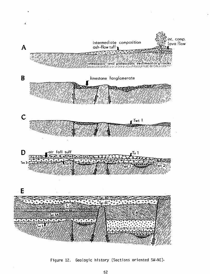
The first Tertiary rocks to be deposited in Lander and Churchill
counties (Stewart et al., 1977; Willden and Speed, 1974) were andesite
and dacite lava flows and ash-flow tuffs about 36 m.y. ago. These
flows accumulated on an erosional surface of low relief, cut into
rocks of Paleozoic and Mesozoic age (Fig. 12A). After these flows
were extruded, faulting in the northern part of the study area
produced sufficient topography to erode large boulders of Triassic
1 imestone and conglomerate to form a fanglomerate up to 80 m thick
(Fig. 12B). After an erosional hiatus, during which the thickness of
the fanglomerate was considerably reduced (Fig. 12C), an ash-flow tuff
(Twt 1) was deposited in a northern canyon. This poorly welded ash
flow tuff was subsequently eroded below the rim of this canyon.
Between 30 and 28 m.y. ago most of the topography remaining was filled
by ash:"'flow tuff units Twt 2,3, and 4, followed by minor ash-falls
and erosion (Fig. 120). A topographic barrier was then created by
block faulting in the vicinity of the McCoy and Wild Horse Mercury
Mines. This topographic barrier blocked the next two ash-flow tuffs,
Twt 6A and B, from being deposited north and northeast of the future
mine site. North of this barrier several cooling units of ash-flow
tuff accumulated (Twt 5), as well as several tens of meters of
tuffaceous sediment. This sediment eventually spilled over the
topographic barrier, and it was partially eroded. The next ash-flow
51
A
B
c
E
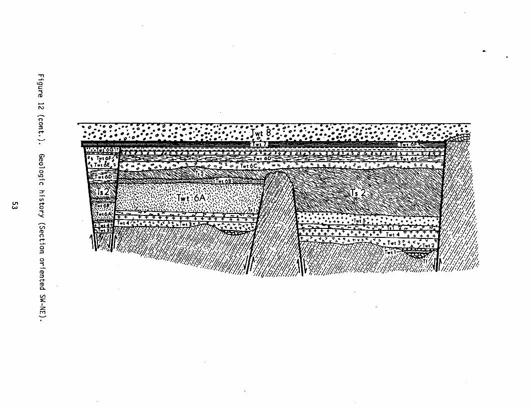
Figure 12. Geologic history (Sections oriented SW-NE).
52
.0
." ...... to C -s (1)
...... N -(') 0 ::s C'+
G") (1) 0 ...... 0 to ...... (')
::s" ...... VI
CJ"1 C'+ W 0
-S '< ...... Vl (1) (') C'+ ..... 0 ::s 0 -S ...... (1) ::s C'+ (1) c.. Vl ::e: I
::z fT1 -
tuff to be deposited, Twt 6C, filled the topographic lows created by
the erosion of the tuffaceous sediment (Fig. 12E).
Approximately 27 m.y. ago Twt 60 was erupted and interfingered
with ash-flow tuffs from the east. This was followed by local
subsidence south of the McCoy Mine, and the emplacement of Twt 6E, F,
and G (Fig. 12E and F). On top of Twt 6F and 6G the 26 m.y. old
locally distributed tuff of McCoy Mine and the 23 m.y. old widespread
Bates Mountain Tuff accumulated.
The onset of Basin and Range faulting occurred between the
deposition of the 23 m.y. old Bates Mountain Tuff and the extrusion of
the 15 m.y. old basalts found in the Clan Alpine Mountains, forming a
series of subparallel cuestas. North-trending faults die out or are
truncated in several places by east-trending faults, which appear to
have been sporadically active from the time of the earliest ash-flow
tuffs through the Bas;n and Range period of faulting.
Since the eruption of the young basalts, erosion and geothermal
activity have been the dominant processes operating in this area.
Some uplift has occurred. causing some alluvial deposits to be deeply
incised. Carbonate-charged waters were vented onto the surface west
of the McCoy Mine, forming an extensive deposit of travertine. In a
few places silica saturated waters also reached the surface, forming
siliceous sinter and apparently sealing several conduits. No surface
activity is now present and these depOSits are today being eroded.
54
i
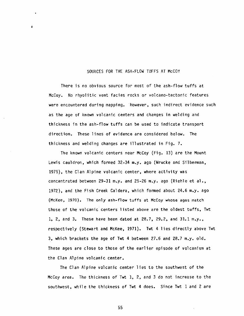
SOURCES FOR THE ASH-FLOW TUFFS AT McCOY
There is no obvious source for most of the ash-flow tuffs at
McCoy. No rhyolitic vent facies rocks or volcano-tectonic features
were encountered during mapping. However, such indirect evidence such
as the age of known volcanic centers and changes in welding and
thickness in the ash-flow tuffs can be used to indicate transport
direction. These lines of evidence are considered below. The
thickness and welding changes are illustrated in Fig. 7.
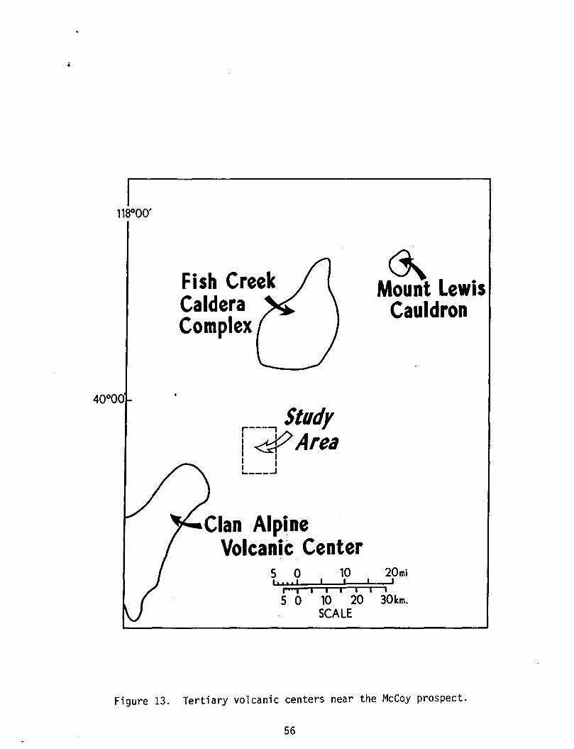
The known volcanic centers near McCoy (Fig. 13) are the Mount
Lewis cauldron, which formed 32-34 m.y. ago (Wrucke and Silberman,
1975), the Clan Alpine volcanic center, where activity was
concentrated between 29-31 m.y. and 25-26 m.y. ago (Riehle et al.,
1972), and the Fish Creek Caldera, which formed about 24.6 m.y. ago
(McKee, 1970). The only ash-flow tuffs at McCoy whose ages match
those of the volcanic centers listed above are the oldest tuffs, Twt
1, 2, and 3. These have been dated at 28.7, 29.2, and 31.1 m.y.,
respectively (Stewart and McKee, 1971). Twt 4 lies directly above Twt
3, which brackets the age of Twt 4 between 27.6 and 28.7 m.y. old.
These ages are close to those of the earlier episode of volcanism at
the Clan Alpine volcanic center.
The Clan Alpine volcanic center lies to the southwest of the
McCoy area. The thickness of Twt 1, 2, and 3 do not increase to the
southwest, while the thickness of Twt 4 does. Since Twt 1 and 2 are
55
i
nsooo'
Fish Creek Caldera Complex
r----, Study i ~Area I I I I L ___ .J
Clan Alpine Volcanic Center
5 0 10 1".1111 I I
.'" i i i i I
5 0 10 20 SCALE
I I
M~t Lewis Cauldron
20mi I
i
30km.
Figure 13. Tertiary volcanic centers near the McCoy prospect.
56
;
confined to the northeastern portion of the McCoy area, and Twt 2 and
3 exhibit a genetic relationship, it is unlikely that these units
originated as far away as the Clan Alpine Mountains. However, the
evidence given above for Twt 4 is consistent with a source in the Clan
Alpine volcanic center.
The distribution of Twt 5 unit is limited to the northeast
quarter of the mapped area. Since this distribution is attributed to
a paleo-topographic barrier south and west of Twt 5,its source area
would be to the north or east of McCoy.
McKee and Stewart (1971) have stated that the most likely source
for the ash-flow tuffs grouped by them into the Edwards Creek Tuff was
to the southwest of the McCoy area. As shown in Figure 7, the only
unit in the Edwards Creek Tuff which increases in thickness or welding
towards the southwest is Twt 6A. Twt 68 and 6C do not occur southwest
or east of the McCoy area. South of McCoy, in Edwards Creek Valley, .
Twt 6C is absent and the welding of 68 decreases. A source area for
Twt 68 and 6C consistent with these facts would be north or west of
the McCoy area.
The only evidence that was found for a source direction of Twt 60
was a decrease in thickness at the reference section at the eastern
edge of Antelope Valley •. However, this reduction in thickness is due
to the compaction of the upper non-welded zone where Twt 60 forms a
compound cooling unit with the Interfingering Tuff. The thickness and
welding of Twt 6E and 6F do not change significantly in the mapped
area, and there is no evidence as to their source area.
The Tuff of McCoy Mine does not exhibit any lateral changes
indicative of a source area direction. This unit has been dated at
about 27 m.y., which could imply an origin in the Clan Alpine
Mountains. The high biotite content of Twt 7 and the 26 m.y. old
volcanics from the Clan Alpine volcanic center is consistent with this
hypothesis.
As discussed in the stratigraphy section, the Bates Mountain Tuff
originated several mountain ranges east of McCoy, in the Simpson Park
Mountains.
58
ALTERATION AND MINERALIZATION
Hydrothermal alteration at McCoy is largely confined to the Wild
Horse and McCoy mine areas. The two mines occupy positions within 1.5
km of each other, both occurring within silicified limestone. The ore
consists of cinnibar and small amounts of mercuric chloride minerals
in films, veinlets, crystal aggregates, and crusts along fractures and
in small cavities. Gangue minerals are quartz, calcite, kaoline,
barite, collophanite, pyrite, iron oxides, and stibnite (Stewart et
al., 1977). The ore bodies are small and erratically distributed in
the fractured and silicified limestone (Dane and Ross, 1942).
Development consists of small open pits, glory holes, trenches, adits,
and an inclined shaft (Stewart et al., 1977).
At the Black Devil mine, 4 km southwest of the Wild Horse mine,
an intercalated sequence of fine- to coarse-grained alluvial sediments
is partly replaced by psilomelane. The mineralization appears to be
confined to an east-west trending graben.
Manganese also occurs in association with the travertine field
and will be discussed in a later section. ,
Silicification and brecciation is found in the Havallah Formation
along several pre-ash-flow tuff faults.
59
HEAT FLOW AND SURFACE HOT WATER DEPOSITS
The Basin and. Range province is an area of high heat flow, thin
crust, deep circulation of fluids along basin faults, and young
igneous activity at the margins. Within the Basin and Range is the
Battle Mountain Heat Flow High, a region of twice normal heat flow.
The Battle Mountain Heat Flow High extends from Lovelock, Nevada in
the south, to the Snake River Plain in the north (Brook et al., 1979).
Amax Inc. drilled over 50 shallow thermal gradient holes in the
mapped area to determine the heat flow. As a result of this survey
three areas of high heat flow and a north-south trend of elevated heat
flow were defined. Heat flow values ranged from 38 to 960 mW/m2 (Fig.
2) (Olsen et al., 1979).
Almost three square kilometers of bedded travertine lie on
alluvium directly northwest of the McCoy Mine. The travertine is
associated with manganese deposits, as is the fault running beneath
the travertine and bounding the McCoy Mine. Manganese deposits also
occur in the Black Devil mine, 4 km southeast of the Wild Horse Mine.
An eroded remnant of travertine mantles a small ridge 5.6 km
south of Hole in the Wall Well no. 2 (Fig. 14). The backbone of this
ridge is a vertical body of amorphous silica, which appears to fill
the feeder vent of the travertine. Cl asts of travertine occur in the
silica, while the travertine surrounding the vent contains silica
filled cavities and pore spaces.
60
Siliceous sinter is found 500 m southwest of the silicified
travertine. The sinter lies in a major drainage and is partially
buried by alluvium. Its extent is not known.
61
DISCUSSION
Several lines of evidence indicate the thermal system at McCoy is
fault controlled. Rocks encountered in drill holes as well as on the
surface include Paleozoic metasediments, Triassic limestones, and
Tertiary volcanics. These rocks have low primary permeability. In
addition, the lack of solution features in limestones penetrated
during drilling and the association of travertine and siliceous
sinters with faults both point towards structural control of the
geothermal system. Five structural trends can be distinguished on the
basis of heat flow, travertine, and siliceous sinter (Fig. 14). The
distinguishing characteristics of these trends are discussed below.
Trend 1
Structural trend 1 consist of one fault which extends northerly
from east of the southern heat flow anomaly to where it intersects
trend 2. Along this path it borders a heat flow high of approximately
627 mW/m2. This fault is covered by alluvium along most of its
path. Trend 1 bends to the northeast before being truncated by an
east-west fault. Located at this bend is a 960 mW/m 2 heat flow
anomaly. There is no surficial evidence of hot spring activity along
trend 1.
Trend 2
In the southern part of the area trend 2 is represented by a
62
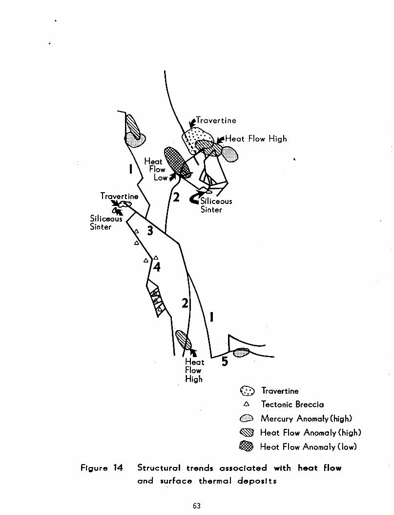
Heat Flow High
@ Travertine
6 Tectonic Breccia
(TID Mercury Anomaly (high)
~ Heat Flow Anomaly (high)
® Heat Flow Anomaly (low)
Figure 14 Structural trends associated with heat flow
and surface thermal deposits
63
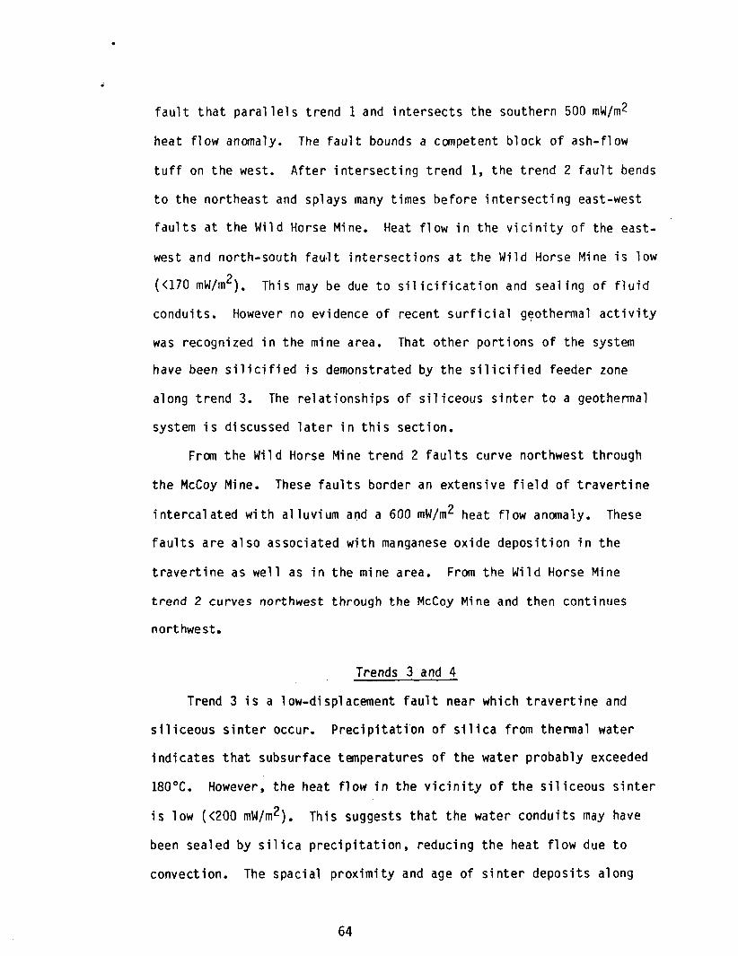
fault that parallels trend 1 and intersects the southern 500 mW/m2
heat flow anomaly. The fault bounds a competent block of ash-flow
tuff on the west. After intersecting trend 1, the trend 2 fault bends
to the northeast and splays many times before intersecting east-west
faults at the Wild Horse Mine. Heat flow in the vicinity of the east
west and north-south fault intersections at the Wild Horse Mine is low
«170 mW/m2). This may be due to silicification and sealing of fluid
conduits. However no evidence of recent surficial g~othermal activity
was recognized in the mine area. That other portions of the system
have been silicified is demonstrated by the silicified feeder zone
along trend 3. The relationships of siliceous sinter to a geothermal
system is discussed later in this section.
From the Wild Horse Mine trend 2 faults curve northwest through
the McCoy Mine. These faults border an extensive field of travertine
intercalated with alluvium a~d a 600 mW/m2 heat flow anomaly. These
faults are also associated with manganese oxide deposition in the
travertine as well as in the mine area. From the Wild Horse Mine
trend 2 curves northwest through the McCoy Mine and then continues
northwest.
Trends 3 and 4
Trend 3 is a low-displac,ement fault near which travertine and
siliceous sinter occur. Precipitation of silica from thermal water
indicates that subsurface temperatures of the water probably exceeded
180°C. However, the heat flow in the vicinity of the siliceous sinter
is low «200 mW/m2). This suggests that the water conduits may have
been sealed by silica precipitation, reducing the heat flow due to
convection. The spacial proximity and age of sinter deposits along
64
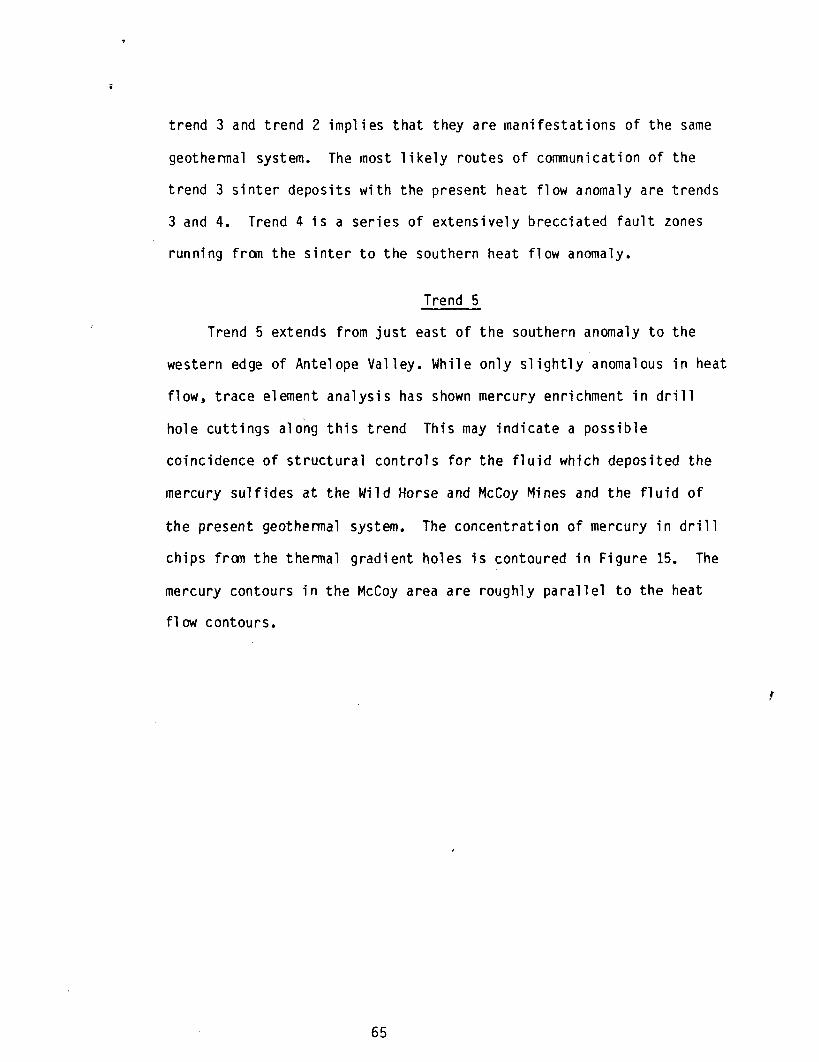
trend 3 and trend 2 implies that they are manifestations of the same
geothermal system. The most likely routes of communication of the
trend 3 sinter deposits with the present heat flow anomaly are trends
3 and 4. Trend 4 is a series of extensively brecciated fault zones
running from the sinter to the southern heat flow anomaly.
Trend 5
Trend 5 extends from just east of the southern anomaly to the
western edge of Antelope Valley. While only slightly anomalous in heat
flow, trace element analysis has shown mercury enrichment in drill
hole cuttings along this trend This may indicate a possible
coincidence of structural controls for the fluid which deposited the
mercury sulfides at the Wild Horse and McCoy Mines and the fluid of
the present geothermal system. The concentration of mercury in drill
chips from the thermal gradient holes is contoured in Figure 15. The
mercury contours in the McCoy area are roughly parallel to the heat
flow contours.
65
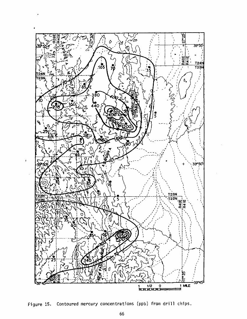
Figure 15.
" ~ II I,
" 'I
:1
.. " ,
I
f
r
I .. I
, , , ,
\
\
r ;
i /
• " I' "
I /
I
" " \ ' t
, I
\ ,
I I I I I I , I I I I II ....
--71 I I I()
IN
~
, \
" 39"50'
I I I
I , l
I
, l
I
, t \ I \
\ \ ,.
, \
\ ,
, t
I
\
, \
\ 1 ,
\
I i I
Contoured mercury concentrations (ppb) from drill chips.
66
CONCLUSIONS
The volcanic rocks at the McCoy geothermal prospect consist of at
least 20 cooling units of rhyolitic ash flow tuffs overlying
intermediate composition lava flows, all of Oligocene age. Only one
cooling unit, Twt 2, was found to be compositionally zoned downward
from a quartz-latite to a rhyolite. The other ash flow tuffs vary
nonsystematically within the rhyolite composition field of O'Connor
{1965}.
No calderas or vent facies related to the ash flow tuffs were
found within the mapped area. The thickness and welding variations of
the ash flow tuffs indicate a northeast to northwest source direction
for units Twt 1, 2, 3, 5, 6B, and 6C. The most likely source area for
units Twt 4 and 7 is the Clan Alpine volcanic center, southwest of the
mapped area. Twt 8 (Bates Mountain Tuff) is known to have originated
west of McCoy, in the Simpson Park Mountains.
The oldest recognized Tertiary faults in the McCoy prospect
produced several east-west trending horsts and grabens. These
structures were active before, during and after ash-flow tuff
deposition. Anomalously high mercury concentration in drill chips,
manganese oxide mineralization, and two mercury mines occur along some
of the east-west trending faults. The mercury and manganese
mineralization post-dates the ash-flow tuffs.
Basin and Range faulting began after the emplacement of the
67
youngest ash-flow tuff 23 m.y. ago. No evidence of the minimum age
for Basin and Range faulting was found at the McCoy prospect.
At least two episodes of hydrothermal activity can be recognized
in the prospect area. The oldest event altered and mineralized the
volcanic and sedimentary rocks, producing the Wild Horse and McCoy
Mercury Mines. The youngest event deposited calcareous travertine,
siliceous sinter, and manganese oxide in and on Ouaternary alluvium.
The geothermal system at McCoy is structurally controlled. The
elongate north-trending heat flow pattern follows the pattern of Basin
and Range faulting, and the major heat flow anomalies occur at the
intersections of north-south and east-west trending faults. This
pattern is also followed by mercury enrichment in drill hole cuttings
(Fig. 15), suggesting that the present-day hot water conduits coincide
with those used by the hydrothermal fluid responsible for the mercury
mineralization at the Wild Horse and McCoy mines.
A recent age for the system may be inferred from the position of
the travertine and siliceous sinter on alluvium and in present-day
drainages.
68
APPENDIX
69
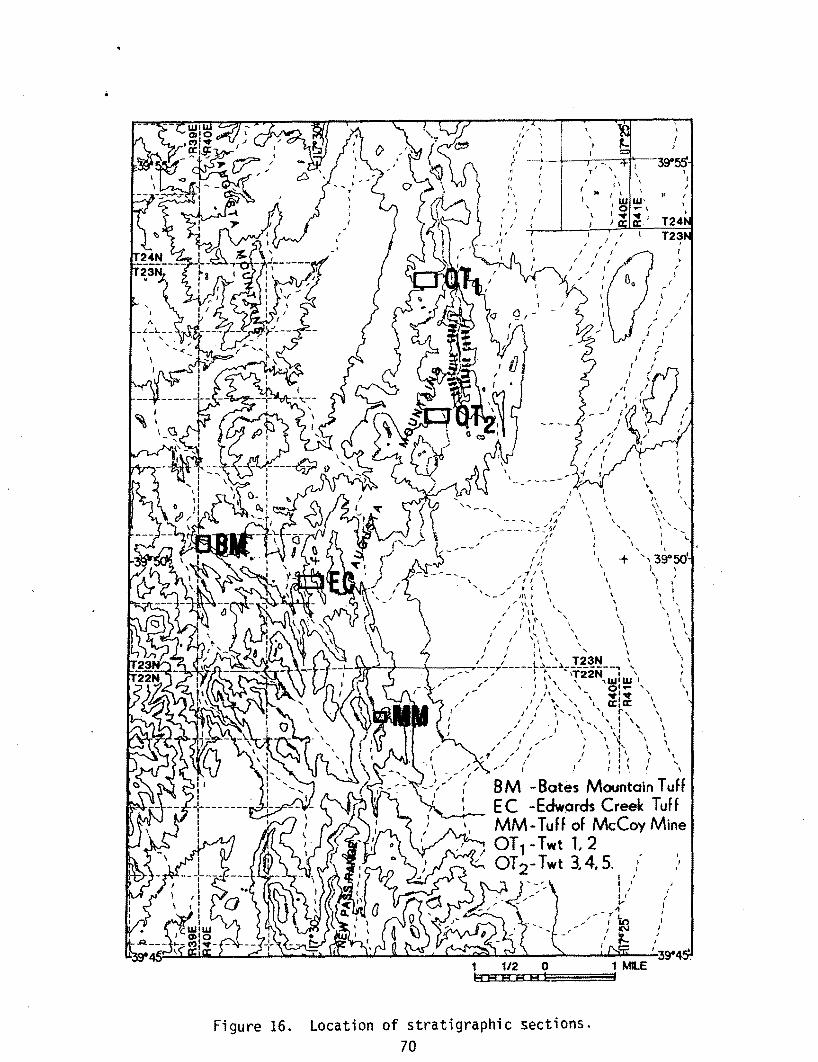
Figure 16.
" \
i
" 1/
I, 0\
"
1 ,
" , " \
'{
, ,
I
, ,
I I
" \
+
I J
r
\
" I I
, ,
\ I
I' , \ \ , , '
/
I
, ,
\ ... ~ , I ,
I
I
',3SO I ,
I ,
,
J \
I i , ,
\
,
\
\ \
"
,
"
... \
, \
BM -Bates Mountain Tuff E C -Edw(Jrds Creek Tuff MM-Tuff of McCoy Mine OT1- Twt 1. 2 OT 2- Twt 3.4.5.
Location of stratigraphic sections. 70
, I I
{ , I f I
I I
I
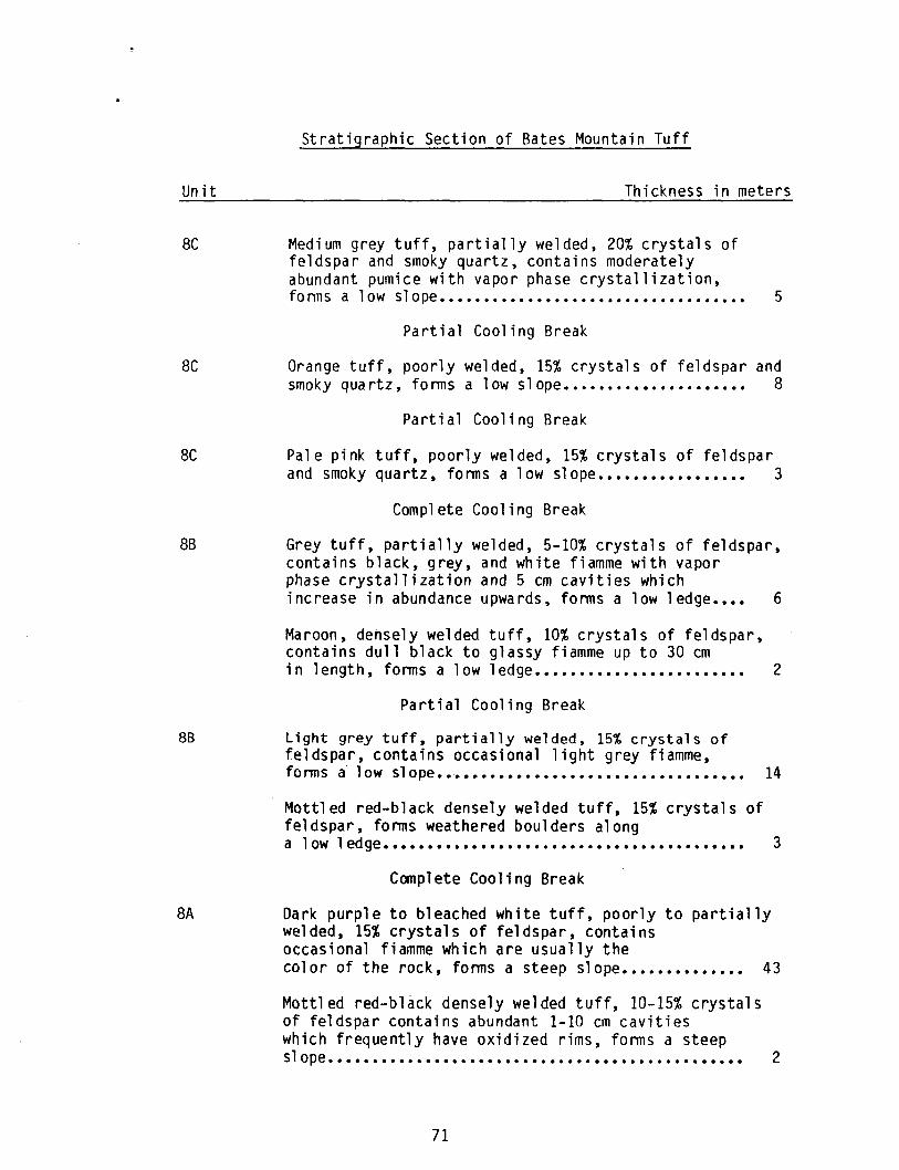
Un it
8C
8C
8C
8B
88
8A
Stratigraphic Section of Bates Mountain Tuff
Thickness in meters
Medium grey tuff, partially welded, 20% crystals of feldspar and smoky quartz, contains moderately abundant pumice with vapor phase crystallization, fonns a low slope ..•.•..............................
Partial Cooling Break
5
Orange tuff, poorly welded, 15% crystals of feldspar and smoky qua rtz, forms a low slope..................... 8
Partial Cooling Break
Pale pink tuff, poorly welded, 15% crystals of feldspar and smoky quartz, forms a low slope................. 3
Complete Cooling Break
Grey tuff, partially welded, 5-10% crystals of feldspar, contains black, grey, and white fiamme with vapor phase crystallization and 5 em cavities which increase in abundance upwards, forms a low ledge.... 6
Maroon, densely welded tuff, 10% crystals of feldspar, contains dull black to glassy fiamme up to 30 cm in length, forms a low ledge........................ 2
Partial Cooling Break
Light grey tuff, partially welded, 15% crystals of feldspar, contains occasional light grey fiamme, fonns a low slope •• -................................. 14
Mottled red-black densely welded tuff, 15% crystals of feldspar, forms weathered boulders along a 1 ow 1 ed ge. • • • • • • • • • • • • • • • • • • • • • • • • • • • • • • • • • • • • • • • • 3
Complete Cooling Break
Dark purple to bleached white tuff, poorly to partially welded, 15% crystals of feldspar, contains occasional fiamme which are usually the color of the rock, forms a steep slope.............. 43
Mottled red-black densely welded tuff, 10-15% crystals of feldspar contains abundant 1-10 em cavities which frequently have oxidized rims, forms a steep slope ....•.......................................... 2
71
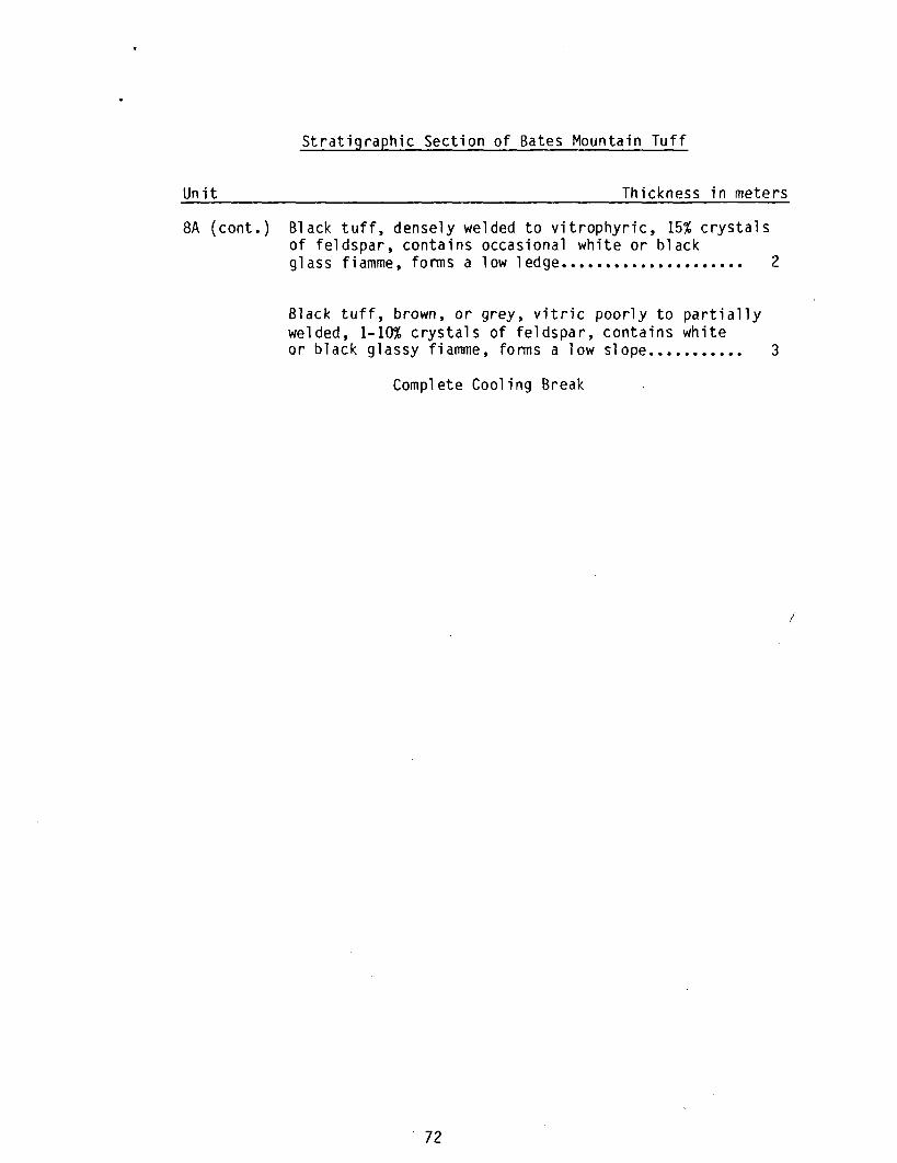
Stratigraphic Section of Bates Mountain Tuff
Unit Thickness in meters
8A (cont.) Black tuff, densely welded to vitrophyric, 15% crystals of feldspar, contains occasional white or black glass fiamme, forms a low ledge..................... 2
Black tuff, brown, or grey, vitric poorly to partially welded, 1-10% crystals of feldspar, contains white or black glassy fiamme, forms a low slope........... 3
Complete Cooling Break
72
!
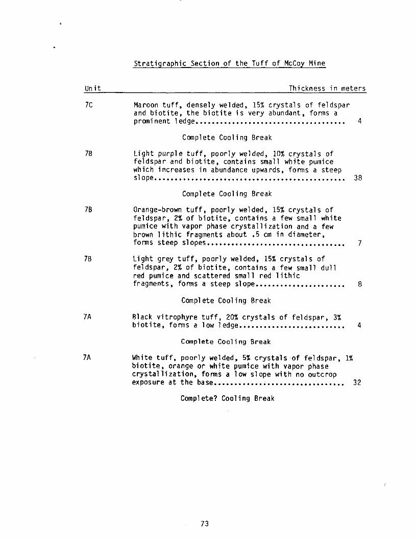
Un it
7C
7B
7B
7B
7A
7A
Stratigraphic Section of the Tuff of McCoy Mine
Thickness in meters
Maroon tuff, densely welded, 15% crystals of feldspar and biotite, the biotite is very abundant, forms a prcxn; nent 1 edge.......................... . .......... 4
Complete Cooling Break
Light purple tuff, poorly welded, 10% crystals of feldspar and biotite, contains small white pumice which increases in abundance upwards, forms a steep s lope. • . . . . . • . • • . . . . . . . . . . . • . • • . . . . • . . . • • . . . . . . . . . • . 38
Complete Cooling Break
Orange-brown tuff, poorly welded, 15% crystals of feldspar, 2% of biotite, contains a few small white pumice with vapor phase crystallization and a few brown lithic fragments about .5 cm in diameter, forms steep slopes ••••••••••••••••••••••••••••••••••
Light grey tuff, poorly welded, 15% crystals of feldspar, 2% of biotite, contains a few small dull red pumice and scattered small red lithic fragments, forms a steep slope ••••••••••••••••••••••
Complete Cooling Break
Black vitrophyre tuff, 20% crystals of feldspar, 3% biotite, forms a low 1 edge ••••••••••••••••••••••••••
Complete Cooling Break
White tuff, poorly welded, 5% crystals of feldspar, 1% biotite, orange or white pumice with vapor phase crystallization, forms a low slope with no outcrop
7
8
4
exposure at the base •••••••••••• ~................... 32
Complete? Cooling Break
73
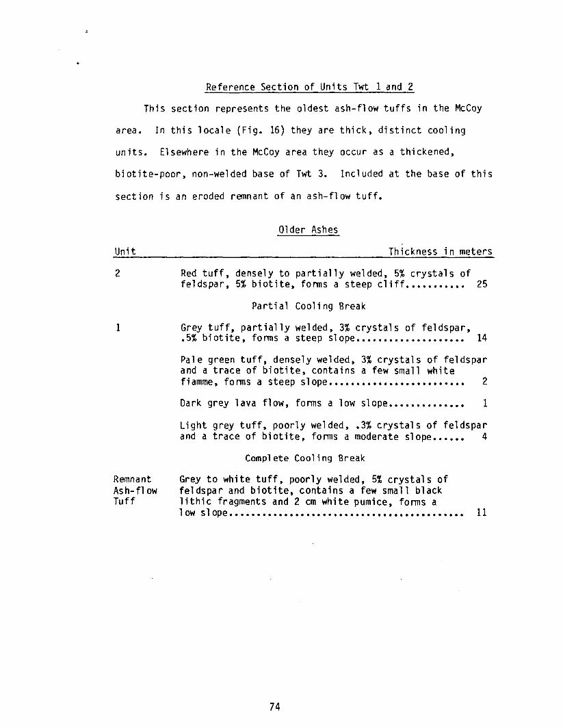
Reference Section of Units Twt 1 and 2
This section represents the oldest ash-flow tuffs in the McCoy
area. In this locale (Fig. 16) they are thick, distinct cooling
units. Elsewhere in the McCoy area they occur as a thickened,
biotite-poor, non-welded base of Twt 3. Included at the base of this
section is an eroded remnant of an ash-flow tuff.
Unit
2
1
Remnant Ash-flow Tuff
01 der Ashes
Thickness in meters
Red tuff, densely to partially welded, 5% crystals of feldspar, 5% biotite, forms a steep cliff ••••••••••• 25
Partial Cooling Break
Grey tuff, partially welded, 3% crystals of feldspar, .5% biotite, forms a steep slope.................... 14
Pale green tuff, densely welded, 3% crystals of feldspar and a trace of biotite, contains a few small white fiamme, forms a steep slope......................... 2
Dark grey lava flow, forms a low slope.............. 1
Light grey tuff, poorly welded, .3% crystals of feldspar and a trace of biotite, forms a moderate slope...... 4
Complete Cooling Break
Grey to white tuff, poorly welded, 5% crystals of feldspar and biotite, contains a few small black lithic fragments and 2cm white pumice, forms a low slope........................................... 11
74
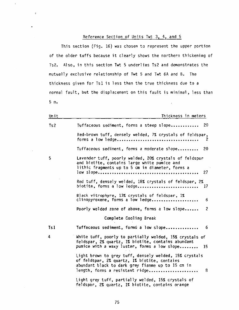
Reference Section of Units Twt 3, 4, and 5
This section (Fig. 16) was chosen to represent the upper portion
of the older tuffs because it clearly shows the northern thickening of
Ts2. Al so, in thi s sect ion Twt 5 underl i es Ts2 and demonstrates the
mutually exclusive relationship of Twt 5 and Twt 6A and B. The
thickness given for Tsl is less than the true thickness due to a
normal fault, but the displacement on this fault is minimal, less than
5 m.
Un it
Ts2
5
Tsl
4
Thickness in meters
Tuffaceous sediment, forms a steep slope............ 20
Red-brown tuff, densely welded, 7% crystals of feldspar, f 0 nn salow 1 ed ge • • • • • • • • • • • • • • • • • • • • • • • • • • • • • • • • • • • 2
Tuffaceous sediment, forms a moderate slope ••••••••• 20
Lavender tuff, poorly welded, 20% crystals of feldspar and biotite, contains large white pumice and lithic fragments up to 5 cm in diameter, forms a low slope ••••••••••••••••••••••••••••••••••••••••••• 27
Red tuff, densely welded, 18% crystals of feldspar, 2% biotite, forms a low ledge.......................... 17
Black vitrophyre, 13% crystals of feldspar, 1% clinopyroxene, forms a low ledge.................... 6
Poorly welded zone of above, forms a low slope...... 2
Complete Cooling Break
Tuffaceous sediment, forms a low slope •••••••••••••• 6
. White tuff, poorly to partially welded, 15% crystals of feldspar, 2% quartz, 1% biotite, contains abundant pumice with a waxy luster, forms a low slope........ 15
Light brown to grey tuff, ,densely welded, 15% crystals of feldspar, 2% quartz, 1% biotite, contains abundant black to dark grey fiamme up to 15 cm in length, forms a resistant ridge..................... 8
Light grey tuff, partially welded, 15% crystals of feldspar, 2% quartz, 1% biotite, contains orange
75
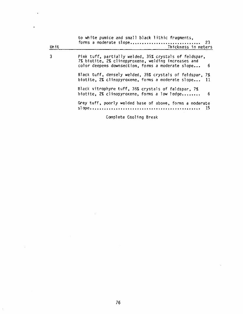
to white pumice and small black lithic fragments, forms a moderate slope •••••••••••••••••••••••••••••• 23
Unit Thickness in meters
3 Pink tuff, partially welded, 35% crystals of feldspar, 7% biotite, 2% clinopyroxene, welding increases and color deepens downsection, forms a moderate slope... 6
Black tuff, densely welded, 35% crystals of feldspar, 7% biotite, 2% clinopyroxene, forms a moderate slope... 11
Black vitrophyre tuff, 35% crystals of feldspar, 7% biotite, 2% clinopyroxene, forms a low ledge........ 6
Grey tuff, poorly welded base of above, forms a moderate slope •••••....•.••••••••.•••...•.•••.•.•.••••.•••••• 15
Complete Cooling Break
76
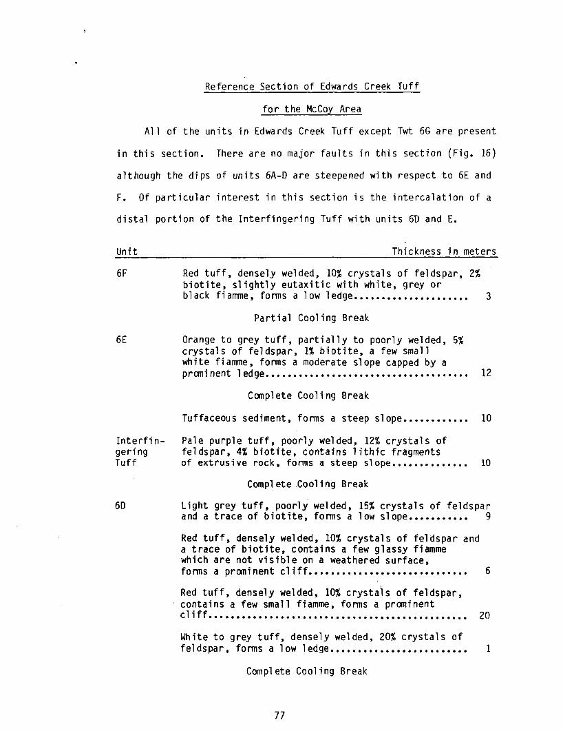
Reference Section of Edwards Creek Tuff
for the McCoy Area
All of the units in Edwards Creek Tuff except Twt 6G are present
in this section. There are no major faults in this section (Fig. 16)
although the dips of units 6A-D are steepened with respect to 6E and
F. Of particular interest in this section is the intercalation of a
distal portion of the Interfingering Tuff with units 60 and E.
Unit
6F
6E
Thickness in meters
Red tuff, densely welded, 10% crystals of feldspar, 2% biotite, slightly eutaxitic with white, grey or black fiamme, forms a low ledge..................... 3
Partial Cooling Break
Orange to grey tuff, partially to poorly welded, 5% crystals of feldspar, 1% biotite, a few small white fiamme, forms a moderate slope capped by a prani nent 1 edge. ••.•.••••••.••.••••.•.••.••••••••••• 12
Complete Cooling Break
Tuffaceous sediment, forms a steep slope............ 10
Interfin- Pale purple tuff, poorly welded, 12% crystals of gering feldspar, 4% biotite, contains lithic fragments Tuff of extrusive rock, forms a steep slope.............. 10
60
Complete Cooling Break
Light grey tuff, poorly welded, 15% crystals of feldspar and a trace of biotite, forms a low slope........... 9
Red tuff, densely welded, 10% crystals of feldspar and a trace of biotite, contains a few glassy fiamme which are not visible on a weathered surface, forms a prominent cliff............................. 6
Red tuff, densely welded, 10% crystals of feldspar, contains a few small fiamme, forms a prominent cliff ••••••••• ~ ••••••••••••••••••••••••••••••••••••• 20
White to grey tuff, densely welded, 20% crystals of feldspar, forms a low ledge......................... 1
Complete Cooling Break
77
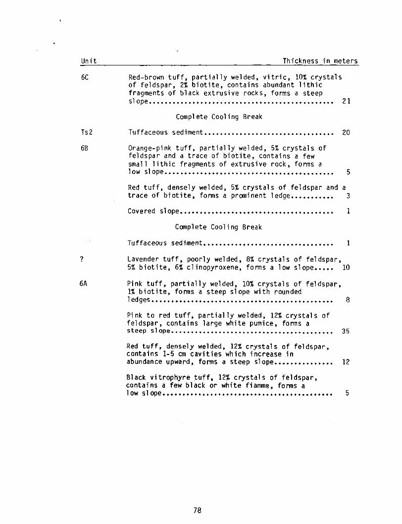
Unit Thickness in meters
6C Red-brown tuff, partially welded, vitric, 10% crystals of feldspar, 2% biotite, contains abundant lithic fragments of black extrusive rocks, forms a steep
Ts2
6B
?
6A
slope ......•••.••........•......•.......•...•.•.••.• 21
Complete Cooling Break
Tuffaceous sediment ••••••••••••••••••••••••••••••••• 20
Orange-pink tuff, partially welded, 5% crystals of feldspar and a trace of biotite, contains a few small lithic fragments of extrusive rock, forms a low 51 ope. •.•••...•. .•. ....••..•.. .••••.•..• •.•. ...• 5
Red tuff, densely welded, 5% crystals of feldspar and a trace of biotite, forms a prominent ledge........... 3
Covered slope....................................... 1
Complete Cooling Break
Tuffaceous sediment................................. 1
Lavender tuff, poorly welded, 8% crystals of feldspar, 5% biotite, 6% clinopyroxene, forms a low slope ••••• 10
Pink tuff, partially welded, 10% crystals of feldspar, 1% biotite, forms a steep slope with rounded 1 ed ges • • • • • • • • • • • • • • • • • • • • • • • • • • • • • • • • • • • • • • • • • • • • • • 8
Pink to red tuff, partially welded, 12% crystals of feldspar, contains large white pumice, forms a steep slope......................................... 35
Red tuff, densely welded, 12% crystals of feldspar, contains 1-5 cm cavities which increase in abundance upward, forms a steep slope............... 12
Black vitrophyre tuff, 12% crystals of feldspar, contains a few black or white fiamme, forms a low slope........................................... 5
78
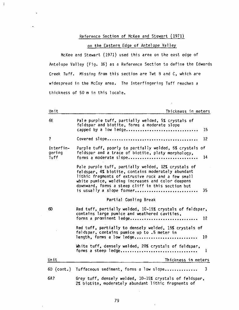
Reference Section of McKee and Stewart (1971)
on the Eastern Edge of Antelope Valley
McKee and Stewart (1971) used this area on the east edge of
Antelope Valley (Fig. 16) as a Reference Section to define the Edwards
Creek Tuff. Missing from this section are Twt Band C, which are
widespread in the McCoy area. The Interfingering Tuff reaches a
thickness of 50 m in this locale.
Unit
6E
?
Interfingering Tuff
60
Unit
Thickness in meters
Pale purple tuff, partially welded, 5% crystals of feldspar and biotite, forms a moderate slope capped by a low ledge............................... 15
Covered slope....................................... 12 Purple tuff, poorly to partially welded, 5% crystals of feldspar and a trace of biotite, platy morphology, forms a moderate slope.............................. 14
Pale purple tuff, partially welded, 12% crystals of feldspar, 4% biotite, contains moderately abundant lithic fragments of extrusive rock and a few small white pumice, welding increases and color deepens downward, forms a steep cliff in this section but is usually a slope former ••••••••••••••••••••••••••• 35
Partial Cooling Break
Red tuff, partially welded, 10-15% crystals of feldspar, contains large pumice and weathered cavities, forms a prominent ledge............................. 12
Red tuff, partially to densely welded, 15% crystals of feldspar, contains pumice up to .5 meter in length, forms a low ledge........................... 10
White tuff, densely welded, 20% crystals of feldspar, forms a steep ledge................................. 1
Thickness in meters
60 (cont.) Tuffaceous sediment, forms a low slope.............. 3
6A? Grey tuff, densely welded, 10-15% crystals of feldspar, 2% biotite, moderately abundant lithic fragments of
79
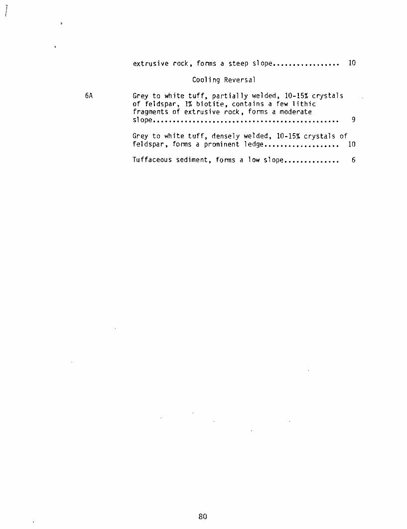
1
6A
extrusive rock, forms a steep slope................. 10
Cooling Reversal
Grey to white tuff, partially welded, 10-15% crystals of feldspar, 1% biotite, contains a few lithic fragments of extrusive rock, forms a moderate slope .•••.•..•.•.••••.•.••••.....•••..•.•.•.......•• 9
Grey to white tuff, densely welded, 10-15% crystals of feldspar, forms a prominent ledge................... 10
Tuffaceous sediment, forms a low slope.............. 6
80
1
REFERENCES
81
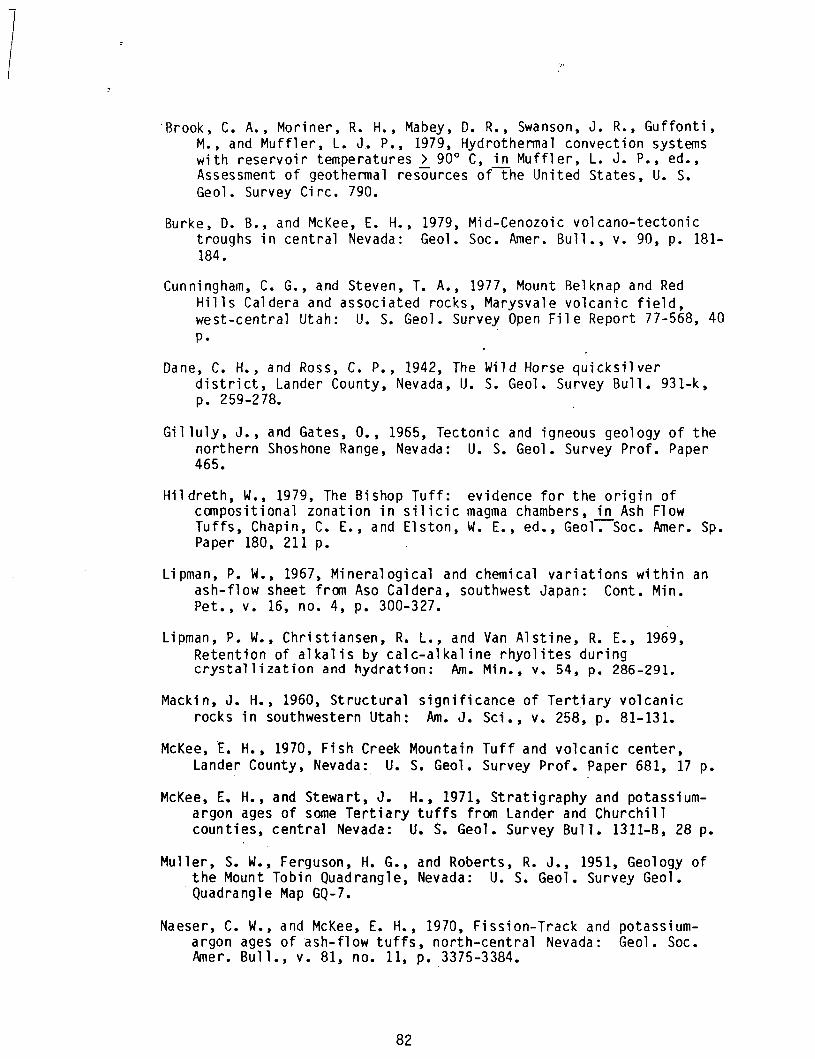
! Brook, C. A., Moriner, R. H., Mabey, D. R., Swanson, J. R., Guffonti,
M., and Muffler, L. J. P., 1979, Hydrothermal convection systems with reservoir temperatures> 90 0 C, in Muffler, L. J. P., ed., Assessment of geothermal resources of-rhe United States, U. S. Geol. Survey Circ. 790.
Burke, D. B., and McKee, E. H., 1979, Mid-Cenozoic volcano-tectonic troughs in central Nevada: Geol. Soc. Amer. Bull., v. 90, p. 181-184.
Cunningham, C. G., and Steven, T. A., 1977, Mount Belknap and Red Hills Caldera and associated rocks, Marysvale volcanic field, west-central Utah: U. S. Geol. Survey Open File Report 77-568, 40 p.
Dane, C. H., and Ross, C. P., 1942, The Wild Horse quicksilver district, Lander County, Nevada, U. S. Geol. Survey Bull. 931-k, p. 259-278.
Gil luly, J., and Gates, 0., 1965, Tectonic and igneous geology of the northern Shoshone Range, Nevada: U. S. Geol. Survey Prof. Paper 465.
Hildreth, W., 1979, The Bishop Tuff: evidence for the origin of compositional zonation in silicic magma chambers, in Ash Flow Tuffs, Chapin, C. E., and Elston, W. E., ed., Geol-.-Soc. Amer. Sp. Paper 180, 211 p.
Lipman, P. W., 1967, Mineralogical and chemical variations within an ash-flow sheet from Aso Caldera, southwest Japan: Cont. Min. Pet., v. 16, no. 4, p. 300-327.
Lipman, P. W., Christiansen, R. L., and Van Alstine, R. E., 1969, Retention of alkalis by calc-alkaline rhyolites during crystallization and hydration: Am. Min., v. 54, p. 286-291.
Macki n, J. H., 1960, Structural significance of Tertiary volcanic rocks in southwestern Utah: Am. J. Sci., v. 258, p. 81-131.
McKee, E. H., 1970, Fish Creek Mountain Tuff and volcanic center, Lander County, Nevada: U. S. Geol. Survey Prof. Paper 681, 17 p.
McKee, E. H., and Stewart, J. H., 1971, Stratigraphy and potassiumargon ages of some Tertiary tuffs from Lander and Churchill counties, central Nevada: U. S. Geol. Survey Bull. 1311-B, 28 p.
Muller, S. W., Ferguson, H. G., and Roberts, R. J., 1951, Geology of the Mount Tobin Quadrangle, Nevada: U. S. Geol. Survey Geol. Quadrangle Map GQ-7.
Naeser, C. W., and McKee, E. H., 1970, Fission-Track and potassiumargon ages of ash-flow tuffs, north-central Nevada: Geol. Soc. Amer. Bull., v. 81, no. 11, p. 3375-3384.
82
Noble, D. C., Smith, V. C., Peck, L. C., 1967, Loss of halogens from crystallized and glassy silicic volcanic rocks: Geochem. et Cosmochem. Acta, v. 31, po. 215-223.
Nockolds, S. R., 1954, Average chemical compositions of some igneous rocks: Bull. Geol. Soc. JVner., v. 65, p. 1007-1032.
O'Connor, J. J., 1965, A classification for quartz rich igneous rocks based on feldspar ratio: U. S. Geol. Survey Prof. Paper 525B, p. B79-B84.
Olson, H. J., Dellechaie, F., Pilkington, H. 0., Lange, A. lo, 1979, The McCoy geothermal prospect: status report of a possible new discovery in Churchill and Lander Counties, Nevada: Geotherm. Resc. Counc., Trans., v. 3, p. 515-518.
Riehle, J. R., McKee, E. H., Speed, R. C., 1972, Tertiary volcanic center, west-central Nevada: Geol. Soc. Amer. Bull., v. 83, p. 1383-1389.
Rosholt, J. N., and Noble, D. C., 1969, Loss of uranium from crystallized silicic volcanic rocks: Earth and Planetary Sci. News Letters, v. 6, p. 268-270.
Rosholt, J. N., Prijana, and Noble, D. C., 1971, Mobility of uranium and thorium in glassy and crystallized silicic volcanic rocks: Econ. Geol., v. 66~· 1971, p. 1061-1069.
Sargent, K. A., and McKee, E. H., 1969, The Bates Mountain Tuff in northern Nye County, Nevada: U. S. Geol. Survey Bull. 1294-E, 12 p.
Scott, R. B., 1971a, Alkali exchange during devitrification and hydration of glasses in ignimbrite cooling units: Jour. Geol., v. 79, p. 100-110.
Scott, R. B., 1971b, Chemical variations in glass shards and interstitial dust of ignimbrite cooling units: Am. J. Sci., v. 270, p. 166-173.
Sil berling, N. J., 1956, "Tracyceras zone" in the Upper Triassic of the western United States: Jour. Paleo., v. 30, no. 5, p. 1147-1153.
Silberling, N. J., and Roberts, R. J., 1962, Pre-Tertiary stratigraphy and structure of northwest Nevada: Geol. Soc. Amer. Spec. Paper 72, 58 p.
Slemmons, D. B., 1966, Guidebook for Nevada earthquake areas: 2nd U.S.-Japan Conf. on Research Related to Earthquake Predictions, 79 p.
Smith, R. L., 1960, Zones and zonal variations in welded ash-flows: U. S. Geol. Survey Prof. Paper 354-F, p. 140-159.
83
Smith, R. L., and Ross, C. S., 1961, Ash-Flow Tuffs: their orlgln, geologic relations, and identification: U. S. Geol. Survey Prof. Paper 366, 80 p.
Stewart, J. H., and McKee, E. H., 1968, Geologic map of the Mount Callaghan quadrangle, Lander County, Nevada: U. S. Geol. Survey Geol. Quadrangle Map GQ-730.
Stewart, J. H., McKee, E. H., and Stager, H. K., 1977, Geology and Mineral deposits of Lander County, Nevada: Nevada Bur. Mines and Geol., Bull. 88, 106 p.
White, D. E., 1970, Geochemistry applied to the discovery, evaluation, and exploration of geotherma) energy resources, in United Nations Symposium on development and utilization of geot~rmal resources, Pisa: Geothermics Spec. Issue, v. 2, p. 58-80.
Willden, R., and Speed, R. C., 1974, Geology and mineral resources of Churchill County, Nevada: Nev. Bur. Mines and Geology, Bull. 83, 95 p.
Wrucke, C. T., and Silberman, M. L., 1975, Cauldron subsidence of Oligocene age at Mount Lewis, northern Shoshone Range, Nevada: U. S. Geol. Survey Prof. Paper 876, 20 p.
84