Embed Size (px)
Citation preview

THE STRUCTURAL DESIGN OF NUCLEAR COMPONENTS IPEN DESIGN BY ANALYSIS EXPERIENCE
Miguel Mattar Neto ([email protected])IPEN-CNEN/SPNuclear Engineering CenterStructural Mechanics Division

IPEN Overview
Structural Mechanics Division Main Activities
Design by Analysis
Stress Categorization and Stress Linearization
Examples
Conclusions
Presentation Topics

IPEN – CNEN/SP is the Nuclear and Energy Research Institute (Instituto de Pesquisas Energéticas e Nucleares)
IPEN is an autarchy of the estate of São Paulo, managed by the Brazilian Federal Government through CNEN, the Brazilian Nuclear Energy Commission, and associated to the University of São Paulo.
IPEN is organized in 12 centers and CEN, the Nuclear Engineering Center, is one of them.
The CEN Structural Mechanics Division has worked since 1980 in the nuclear reactors components design.
IPEN Overview
1980 – 1995 – Structural design of nuclear components for the Brazilian Navy Submarine Nuclear Propulsion Program
1995 – present – Structural design of nuclear components for Angra 1 and Angra 2 Nuclear Power Plants
1995 – present – Structural design of nuclear components for the nuclear research reactor IEA-R1
1995 – present – Structural design of mechanical components for the industrial sector
Structural Mechanics Division Main Activities

Until the early 1960s structural design rules were mainly based on accumulated experience and relatively simple mechanics.
Two stimuli led to the change on this approach:•The development of nuclear power in which safety requirements – in particular protection against radiation hazards - required more stringent structural analysis and evaluation methods than had been practisedbefore.•The desire to take advantage of contemporary advance in the understanding of structural behavior so as to eliminate potential weaknesses in the existing methods whist at the same time reduce over-conservatism in conventional design.
Changes in design philosophy might permit use of higher allowable stresses without reduction in safety.
Design by Analysis

The change in design philosophy was to base the structural design on a more detailed evaluation of the actual stresses making use of the plasticity theory, fracture mechanics and fatigue design techniques to establish appropriate allowable stresses.
This approach reduces the level of uncertainty in the design thus allowing safety margins - essentially an amalgam of true conservatism and lack of knowledge – to be estimated with greater confidence and adjusted accordingly.
Design by Analysis
The design by analysis procedure is intended to guard against possible failure modes by performing a detailed stress analysis of the structure. The failure modes usually considered for mechanical components are:
•Excessive elastic deformation including elastic instability.•Excessive plastic deformation.•Brittle fracture.•Stress rupture/creep deformation (inelastic).•Plastic instability - incremental collapse.•High strain - low cycle fatigue.•Stress corrosion.•Corrosion fatigue.
Background to Design by Analysis

Three failure modes to be considered:•Excessive plastic deformation.•Plastic instability - incremental collapse.•High strain - low cycle fatigue.
These failure modes are precluded by failure criteria based on limit load theory, shakedown theory and fatigue theory, respectively. The elastic stresses calculated in the analysis are related to these specific failure criteria by decomposing the elastic stress field into three classes of stress with different degrees of significance and different allowable values:
•Primary stress is an equilibrium stress field associated with gross plastic deformation under static loading.•Secondary stress arises from compatibility requirements and (when taken with primary stress) is associated with ratcheting under cyclic loading.•Peak stress highly localized (occurring at local structural discontinuities) and is associated with fatigue failure under cyclic load.
Background to Design by Analysis

There are definitions of stress categories and example classifications for mechanical components configurations under a variety of loading conditions.
The designer is required to categorize the calculated stress into primary, secondary and peak constituents and apply specified allowable stress limits.
The magnitude of the allowable values assigned to the various stress categories reflects the nature of their associated failure mechanisms, therefore it is essential that the categorization procedure is performed correctly.
Stress categorization is probably the most difficult aspect of the design byanalysis procedure and paradoxically the problem has become more difficultas stress analysis techniques have improved.
Design by Analysis Stress Categorization

When the design by analysis procedure was introduced, the dominant analysis technique in pressure vessel design was thin shell discontinuity analysis.
This is reflected in the definitions of stress categories, which are based on the assumption of shell theory stress distributions: membrane and bending stresses. It is therefore difficult to reconcile the calculated stresses and the categories unless the design is based on shell analysis.
In current practice, the design by analysis is performed using the Finite Element Method (FEM). Various types of finite element models can be created using a variety of element types.
Many pressure vessels can be modeled using shell elements which are relatively easy to generate, are computationally efficient and give results in the form of membrane: and bending stresses.
Design by Analysis Stress Categorization

However, shell models cannot easily incorporate construction details such as reinforcement, fillets, etc., nor can through-thickness effects be considered in detail.
To include these effects, solid elements - based on 2-D or 3-D solid mechanics - must be used. Solid finite element models may be create directly from solid models but have the real problem with categorizing the calculated stress, which is not in the membrane plus bending format.
A great deal of effort has been expended trying to formulate procedures to aid the designer perform rigorous stress categorization for solid finite element models.
The most common method is to apply stress linearization procedures to specific regions of the model to calculate constant (membrane) and linear (bending) stress distributions giving the same net section forces andmoments as the solid finite element stress distributions.
Design by Analysis Stress Categorization
Another approach to avoid the idea of capturing an inelastic behavior through an elastic analysis by performing the stress categorization is to do inelastic analyses, directly.
In the past, the inelastic approach was simply impracticable for most analystsbut advance computer technology and non-linear finite element methodsmake inelastic analysis viable alternative to the elastic analysis approach formany designers.
It is therefore likely that inelastic analysis will become much more widely used in pressure vessel design by analysis.
Design by Analysis Stress Categorization

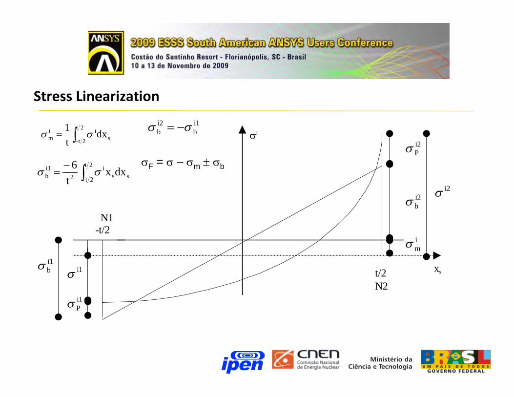
Stress Linearization
Stress Linearization
xs
i
i2P
i2b
i2
im
t/2N2
N1-t/2
i1b i1
i1P
2t
2t sii
m dxt1
2t
2t- ssi
2i1b dxx
t6
i1b
i2b
F = – m b

Stress Linearization
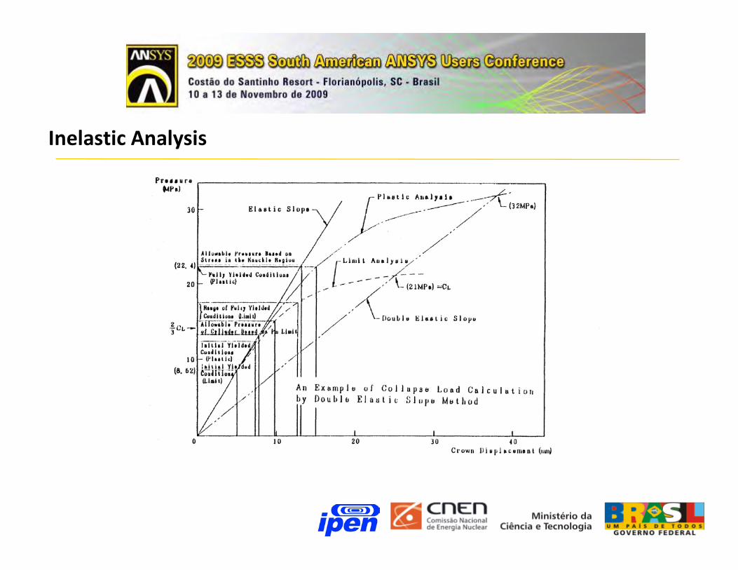
Inelastic Analysis
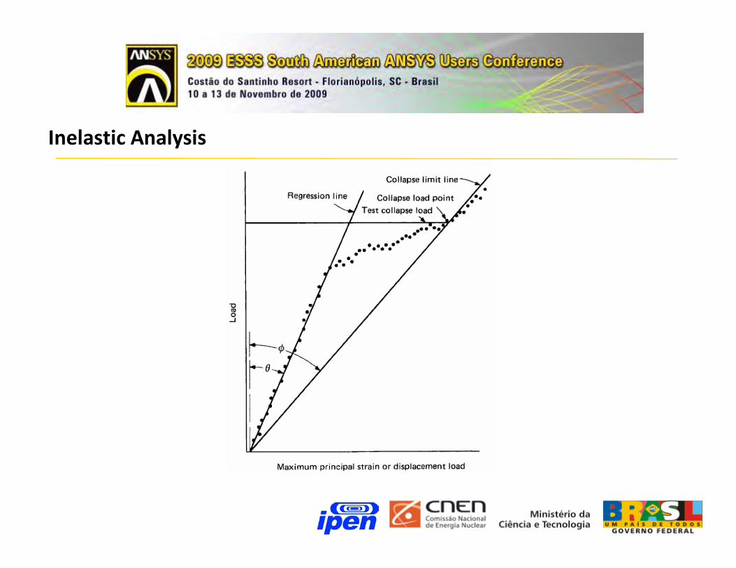
Inelastic Analysis

1983 – Processing ANSYS with input card decks and remote card reader
1986 – Processing ANSYS in terminals connected to mainframe
1990 – Processing ANSYS in terminals connected to workstation
1995 – present – Processing ANSYS in PCs
Design by Analysis Using ANSYS

Brazilian Navy Submarine Nuclear Propulsion Program
Lug-cylinder attachment
Design by Analysis Using ANSYS - Examples

Brazilian Navy Submarine Nuclear Propulsion Program
Lug-cylinder attachment
Design by Analysis Using ANSYS - Examples
Allowable load conditions from elastic-plastic FEA
Collapse forces in the lugs (MN) from elastic-plastic FEA
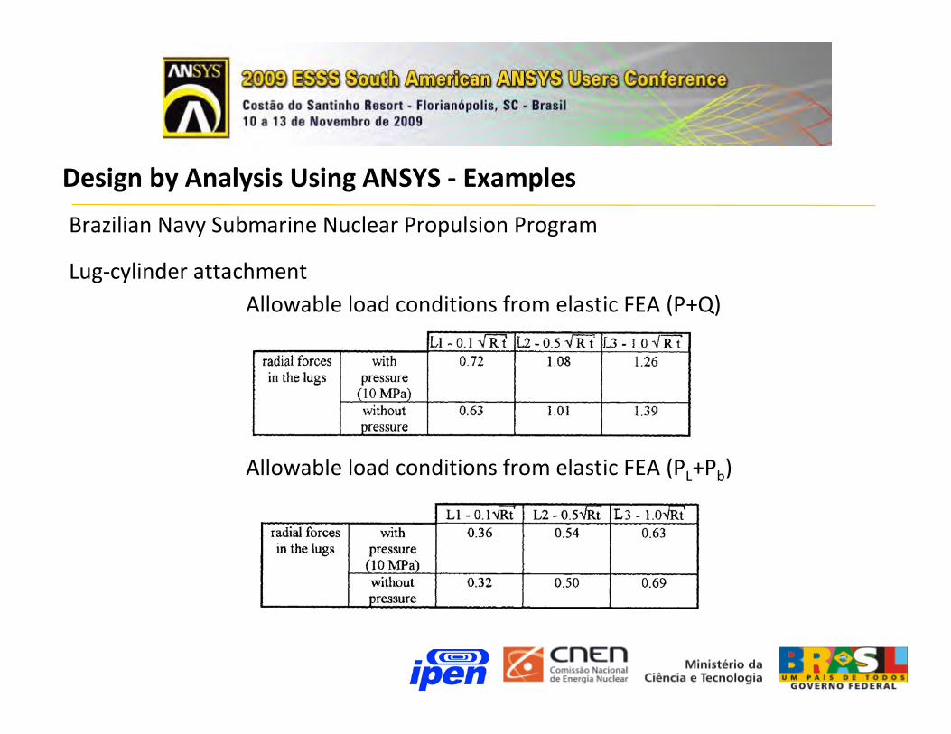
Brazilian Navy Submarine Nuclear Propulsion Program
Lug-cylinder attachment
Design by Analysis Using ANSYS - Examples
Allowable load conditions from elastic FEA (P+Q)
Allowable load conditions from elastic FEA (PL+Pb)

Brazilian Navy Submarine Nuclear Propulsion Program
Reactor Pressure Vessel
Design by Analysis Using ANSYS - Examples

Brazilian Navy Submarine Nuclear Propulsion Program
Reactor Pressure Vessel Internals
Design by Analysis Using ANSYS - Examples

Brazilian Navy Submarine Nuclear Propulsion Program
Radial Cylindrical Nozzle in a Pressure Vessel
Design by Analysis Using ANSYS - Examples
Rboct boc
t ref
r con
R vas
t vas
Rboc = 130 mm
tboc = 16 mm
tref = 55 mm
rcon = 50 mm
Rvas = 1016 mm
tvas = 98 mm
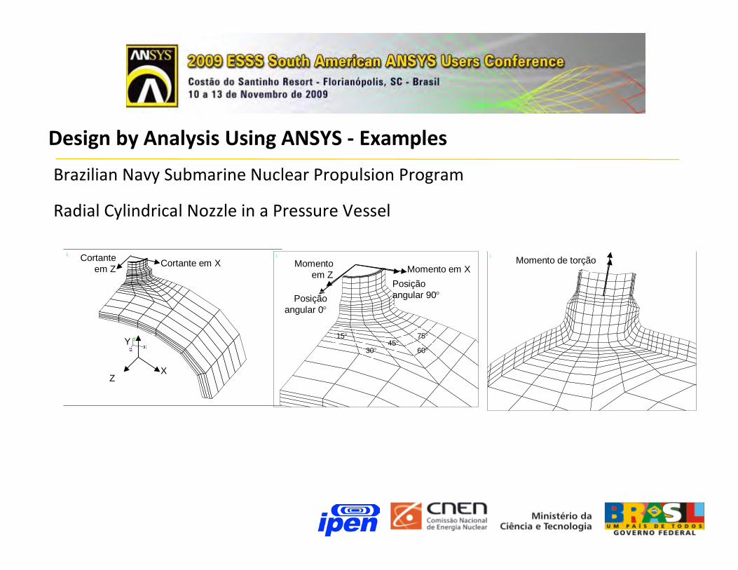
Brazilian Navy Submarine Nuclear Propulsion Program
Radial Cylindrical Nozzle in a Pressure Vessel
Design by Analysis Using ANSYS - Examples
1
XY
Z
Cortante em Z Cortante em X
XZ
Y
1 Momento de torção1
Momento em XMomento em Z
Posição angular 0
Posição angular 90
4530
15
60
75
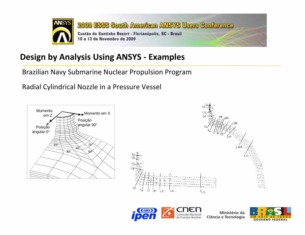
Brazilian Navy Submarine Nuclear Propulsion Program
Radial Cylindrical Nozzle in a Pressure Vessel
Design by Analysis Using ANSYS - Examples
1
Momento em XMomento
em Z
Posição angular 0
Posição angular 90
4530
15
60
75

Brazilian Navy Submarine Nuclear Propulsion Program
Radial Cylindrical Nozzle in a Pressure Vessel
Design by Analysis Using ANSYS - Examples
Internal pressure, only
Elastic FEA – padm = 15,53 MPa
Limit load FEA – padm = 15,83 MPa

Brazilian Navy Submarine Nuclear Propulsion Program
Radial Cylindrical Nozzle in a Pressure Vessel
Nozzle loads, only
Design by Analysis Using ANSYS - Examples
1,90E81,64E8Torsion moment Y (N mm)
1,64E81,43E8Bending moment Z (N mm)
1,64E81,43E8Bending moment X (N mm)
6,22E55,39E5Shear force Z (N)
6,09E55,39E5Shear force X (N)
Limit Load - FEAElastic – FEALoad

Brazilian Navy Submarine Nuclear Propulsion Program
Radial Cylindrical Nozzle in a Pressure Vessel
Nozzle loads + internal pressure (12,3 MPa)
Design by Analysis Using ANSYS - Examples
(*)1,42E8Torsion moment Y (N mm)
1,55E81,23E8Bending moment Z (N mm)
1,52E81,27E8Bending moment X (N mm)
4,83E54,66E5Shear force Z (N)
4,83E54,79E5Shear force X (N)
Limit Load - FEAElastic – FEALoad

Angra 2 Nuclear Power Plant
Spent Fuel Compact Storage Racks
Design by Analysis Using ANSYS - Examples

Angra 2 Nuclear Power Plant
Spent Fuel Compact Storage Racks
Design by Analysis Using ANSYS - Examples

Angra 2 Nuclear Power Plant
Spent Fuel Compact Storage Racks
Design by Analysis Using ANSYS - Examples
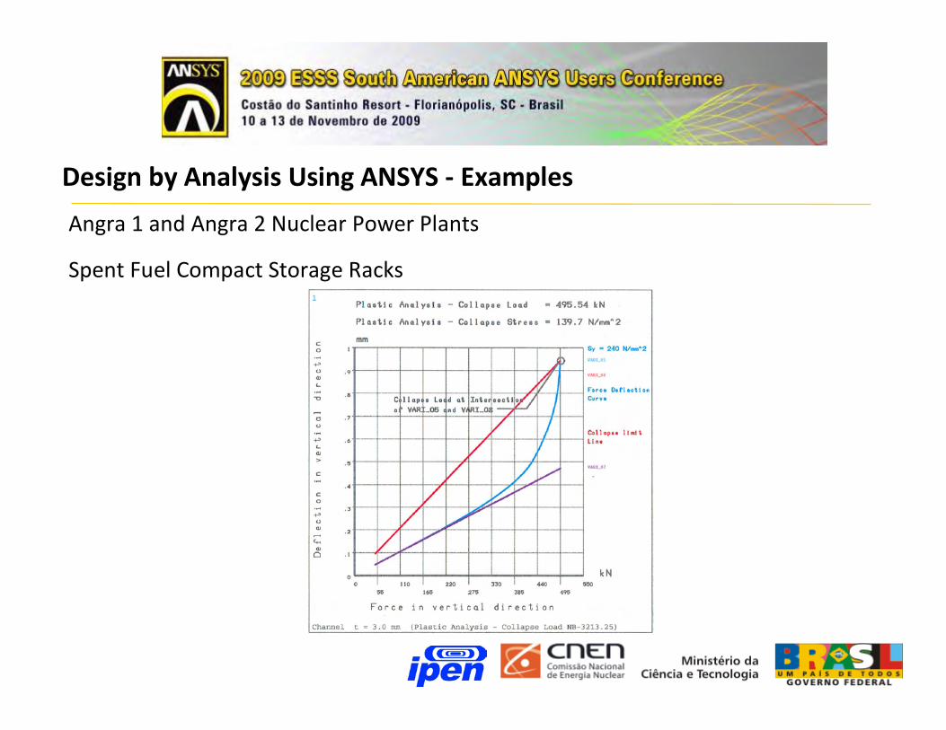
Angra 1 and Angra 2 Nuclear Power Plants
Spent Fuel Compact Storage Racks
Design by Analysis Using ANSYS - Examples

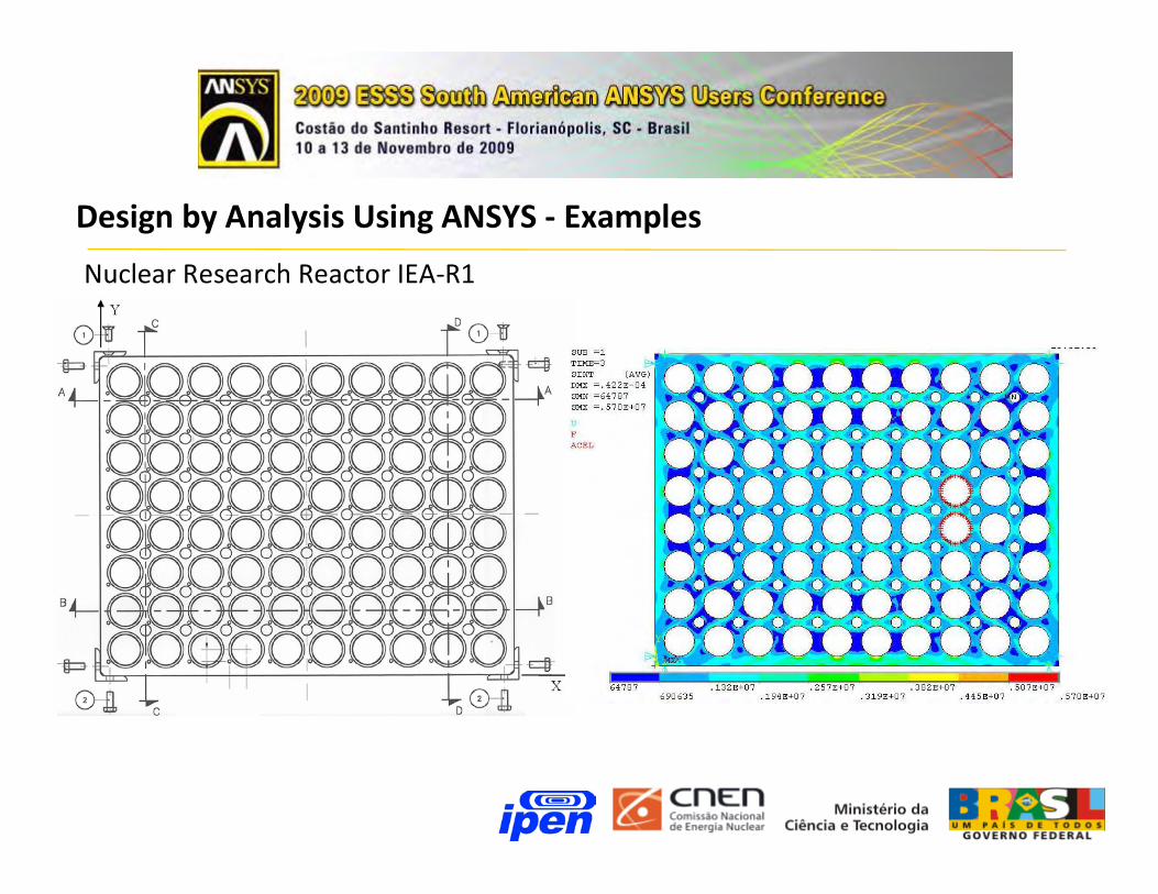
Nuclear Research Reactor IEA-R1
Core Support Plate
Design by Analysis Using ANSYS - Examples
Nuclear Research Reactor IEA-R1
Core Support Plate
Design by Analysis Using ANSYS - Examples
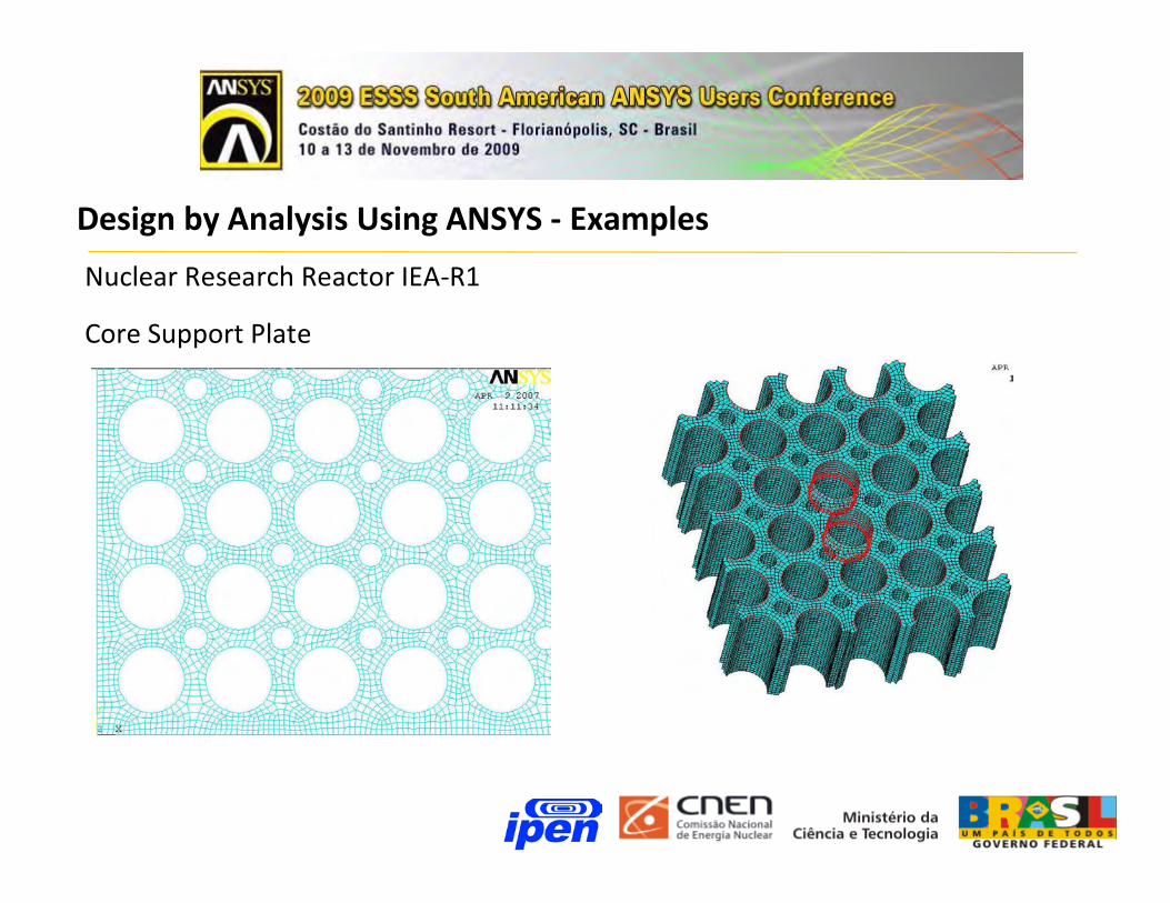
Nuclear Research Reactor IEA-R1
Core Support Plate
Design by Analysis Using ANSYS - Examples

Nuclear Research Reactor IEA-R1
Core Support Plate
Design by Analysis Using ANSYS - Examples
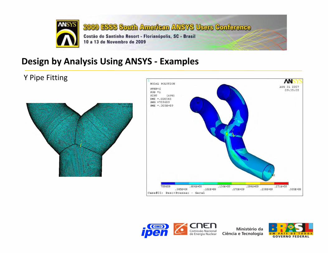
Y Pipe Fitting
Design by Analysis Using ANSYS - Examples

Compressor Housing (with EMBRACO)
Design by Analysis Using ANSYS - Examples

Compressor Housing (with EMBRACO)
Design by Analysis Using ANSYS - Examples
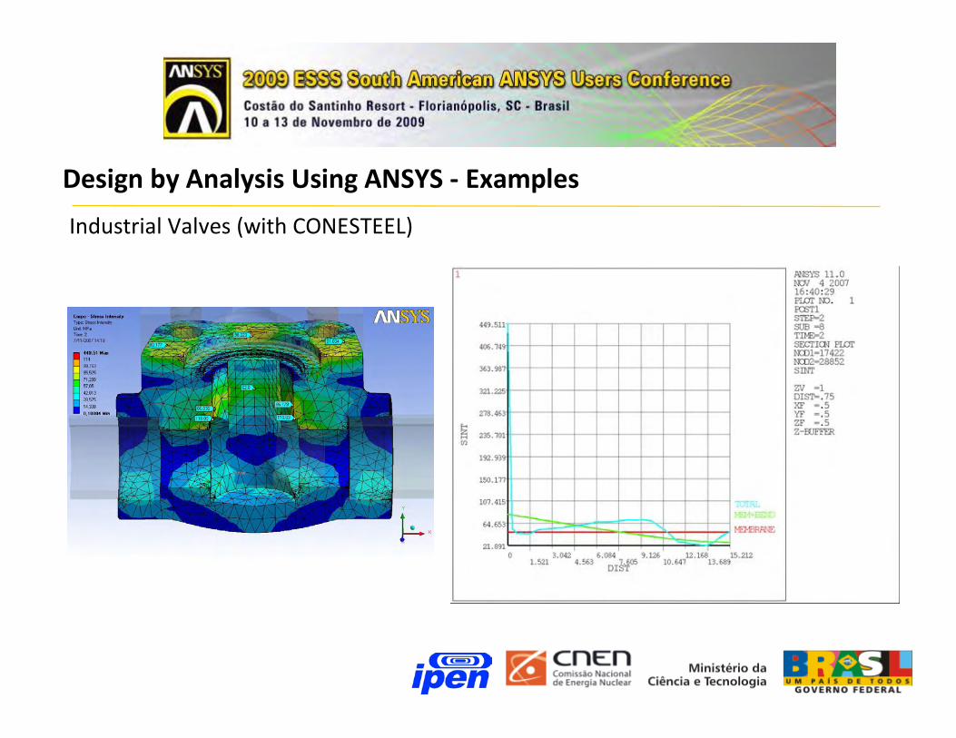
Industrial Valves (with CONESTEEL)
Design by Analysis Using ANSYS - Examples
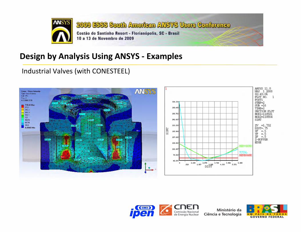
Industrial Valves (with CONESTEEL)
Design by Analysis Using ANSYS - Examples