Embed Size (px)
Citation preview

The Study on Disaster Risk Management for Narayangharh-Mugling Highway Technical Guide
JICA 5 - 22 February 2009
5.5 Design and Construction of Ground Anchor Works
Ground anchors are reliable, but costly compared with other countermeasures. This method has been applied increasingly to artificial landslides to cut off the toe of the landslide. Compared with rock bolts and soil nailing, ground anchors have a relatively large resistance to sliding force and are therefore used to stabilize relatively large-scale slope failures.
5.5.1 Purpose
Ground anchors are intended to prevent landslides through the tensile strength of high tensile strength steel wire or bars installed across the slip surface.
5.5.2 Design of Ground Anchor
When the slope of a landslide area or sliding surface is relatively steep, ground anchors are more effective. Figure 5.5.1 gives a typical example of a landslide stabilized with ground anchors.
Figure 5.5.1 Typical Example of a Landslide Stabilized by Ground Anchors
(1) Design Procedure
Figure 5.5.2 shows the design flowchart for ground anchors. Important considerations for ground anchors are the bearing capacity of the ground under the bearing plate and the bond strength between the anchor grout and rock at the attachment point. In planning ground anchors, a bond strength test at the attachment is to be carried out.
Landslide unsuited cutting work
Bedrock
Road
Ground anchor +Concrete crib

The Study on Disaster Risk Management for Narayangharh-Mugling Highway Technical Guide
JICA 5 - 23 February 2009
Further, in planning and designing ground anchors, at least the following site tests should be performed at intervals of 20 to 30 m.
a) Bond strength test at fixation part (extraction test)
b) Bearing capacity test of soil mass under the bearing plate
Figure 5.5.2 Design Flowchart for Ground Anchors
(2) Stability Analysis and Calculation of the required Preventive Force
The required preventive power of the anchors shall be obtained from the following Equation, as
Stability analysis
Calculation of the required preventive force
Determination of type of anchor and steel material
Initial arrangement of anchors
Design of bearing plate
Calculation of the fixation length
Is anchor suitable?
Selection of anchor functions
Calculation of the design anchor power
Is fixation length suitable?
END
No
Yes
Is bearing plate suitable?
No
No
Yes
Yes
The Study on Disaster Risk Management for Narayangharh-Mugling Highway Technical Guide
JICA 5 - 24 February 2009
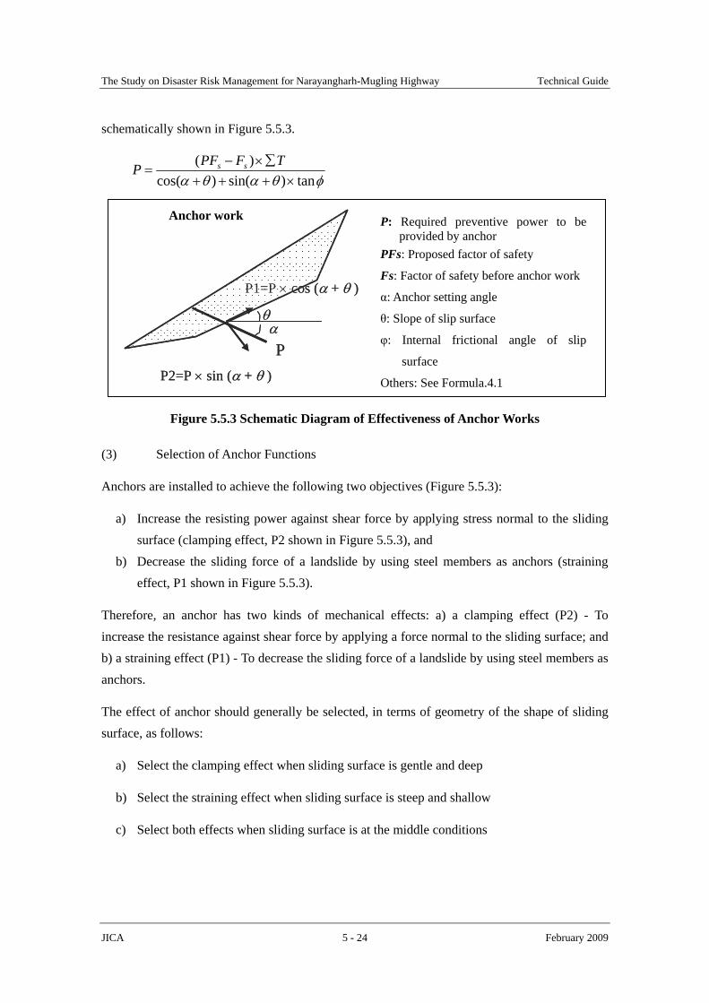
schematically shown in Figure 5.5.3.
φθαθα tan)sin()cos()(
×+++∑×−
=TFPFP ss
Figure 5.5.3 Schematic Diagram of Effectiveness of Anchor Works
(3) Selection of Anchor Functions
Anchors are installed to achieve the following two objectives (Figure 5.5.3):
a) Increase the resisting power against shear force by applying stress normal to the sliding surface (clamping effect, P2 shown in Figure 5.5.3), and
b) Decrease the sliding force of a landslide by using steel members as anchors (straining effect, P1 shown in Figure 5.5.3).
Therefore, an anchor has two kinds of mechanical effects: a) a clamping effect (P2) - To increase the resistance against shear force by applying a force normal to the sliding surface; and b) a straining effect (P1) - To decrease the sliding force of a landslide by using steel members as anchors.
The effect of anchor should generally be selected, in terms of geometry of the shape of sliding surface, as follows:
a) Select the clamping effect when sliding surface is gentle and deep
b) Select the straining effect when sliding surface is steep and shallow
c) Select both effects when sliding surface is at the middle conditions
Anchor work P: Required preventive power to be provided by anchor
PFs: Proposed factor of safety
Fs: Factor of safety before anchor work
α: Anchor setting angle
θ: Slope of slip surface
φ: Internal frictional angle of slip
surface
Others: See Formula.4.1
P
P1=P × cos (α + θ )
P2=P × sin (α + θ )
αθ
P
P1=P × cos (α + θ )
P2=P × sin (α + θ )
αθ

The Study on Disaster Risk Management for Narayangharh-Mugling Highway Technical Guide
JICA 5 - 25 February 2009
(4) Arrangement of Anchors
The position, direction and intervals of anchor installation shall be determined during the initial stage of design.
a) In principle, ground anchor work should be planned on the lower slope of a landslide or unstable area, as conceptually shown in Figure 5.5.4. In addition, when the slope of a landslide area or sliding surface is relatively steep, ground anchors are more effective.
Figure 5.5.4 Conceptual Layout of Ground Anchors
b) The direction of anchoring should be parallel to the direction of movement of the landslide. The driving force of a landslide in the direction of movement is the biggest.
c) The inclination of the anchors in a range from + 10˚ to -10˚ from horizontal plane must be avoided for the reasons related to anchor installation, such as residual slime, bleeding of grout, etc.
d) Ground anchors should be installed at a spacing of at least 2 meters or more in rows. Anchor interval should be determined based on the interaction between anchors, which can be verified by reviewing anchor power, diameter of anchors, depth and ground properties.
(5) Calculation of Design Anchor Power
The design anchor power (Td) is calculated by using the following formulas:
( ) ( ) NBPTd ⋅
++⋅+=
βαφβα costansin
Where,
P (kN/m2) = Required preventive power
Sliding surface
Ground anchorRoad
Concrete crib work
a) Good layout b) Bad layout
Sliding surface
Ground anchorRoad
Concrete crib work

The Study on Disaster Risk Management for Narayangharh-Mugling Highway Technical Guide
JICA 5 - 26 February 2009
α (degree) = Anchor setting angle (the angle to a perpendicular axis)
β(degrees) = Angle of slope of the sliding surface
φ (degrees) = Internal frictional angle of sliding surface
B (m) = Interval between anchors in horizontal direction
N= Number of anchors set in vertical direction
(6) Determination of Type of Anchor and Steel Material
Generally, the type of anchor is determined by comparing the tension strength of steel material with the skin frictional resistance between the ground and the grout as well as the allowable adhesive stress between the tendon and the grout.
(7) Determination of Fixation Length
Figure 5.5.5 gives the structural description of an anchor.
Fixation length should be 3 to 10 meters. If the fixation length is longer than the upper limit, 10 m, the allowable anchor force will be largely decreased. When the obtained anchor power at fixation length of 10 m can not meet the allowable anchor extraction force, the anchor power can be increased by enlarging boring diameter, not by extending fixation length
Figure 5.5.5 Outline of Anchor Structure
Pressure bearing Plate Anchor materials (steel wire or bar)
Sheath
L1: Free length of anchor
L2: Fixation length of anchor
L1+L2: Overall anchor length
L1
L2
Tendon
Grout
Rust-proof oil
Anchoring device
Cap on the steel part

The Study on Disaster Risk Management for Narayangharh-Mugling Highway Technical Guide
JICA 5 - 27 February 2009
In addition, the free length of an anchor should be more than its fixation length or more than 4 m. If the free length of an anchor is too short, stress will be applied to an anchored structure by anchors themselves via the ground or sufficient bearing capacity against pull-out force can not be obtained because the shear resistance of the ground or the weight of a soil mass is small. The free length of an anchor should be determined so that the coupling portion of anchors is secured firmly to rigid bedrock in an unmovable stratum deeper than sliding surface. The rigid bedrocks for faxing the anchors should be confirmed through borehole investigation.
To allow the design anchor power to meet the allowable anchor extraction force, the length of contact between the ground and the grout must be compared with that between a tendon and grout. Whichever is longer should be defined as the fixation length.
abs
dsa D
Tl
τ××=
14.3
aga
d
DTf
laτ××
×=
14.3
Where,
lsa (m) = Required length between the tendon and the grout
la (m) = Required length of contact between the soil and the grout
Td (N/piece) = Design anchor power
DS (m) = Diameter of a tendon
τab (N/m2) = Allowable adhesive stress between the tendon and the grout (Table 5.5.1)
f = Safety factor (generally be defined as 2.5)
DA (m) = Diameter of the anchor
τag (N/cm2) = Skin frictional resistance (Table 5.5.2)
Table 5.5.1 Recommended Allowable Adhesive Stresses
Standard Ground Design Strength (unit: N/cm2) 240 300 400 1. Prestressing steel wire 2. Prestressing steel bar 3. Standard prestressing steel wire 4. Multi-standard prestressing steel wire
80 90 100 Type of tendon
5. Deformed prestressing steel bar 160 180 200 Notes: (1) 1 kgf/cm2 = 10 N/cm2, (2) unit: N/cm2. Source: Modification from Highway Earthwork Series, MANUAL FOR SLOPE PROTECTION, Published by Japan
Road Association, March 1999.

The Study on Disaster Risk Management for Narayangharh-Mugling Highway Technical Guide
JICA 5 - 28 February 2009
Table 5.5.2 Recommended Skin Frictional Resistance of Anchors
Type of Ground Frictional Resistance (N/cm2) Hard rock 150 to 250 Soft rock 100 to 150 Weathered rock 60 to 100
Bedrock
Mudstone 60 to 120 10 10 to 20 20 17 to 25 30 25 to 35 40 35 to 45
Sand and gravel N value
50 45 to 70 10 10 to 14 20 18 to 22 30 23 to 27 40 29 to 35
Sand N value
50 30 to 40 Cohesive soil Representative Cohesion C 10C
Notes: (1) 1 kgf/cm2 = 10 N/cm2. Source: Modification from Highway Earthwork Series, MANUAL FOR SLOPE PROTECTION, Published by Japan
Road Association, March 1999.
(7) Design of Bearing Plates
Cribs, plates or cross-shaped blocks set on the surface of the ground are used as pressure bearing plates. The most appropriate pressure bearing plate is selected in consideration of specifications, operational efficiency, cost-effectiveness, maintenance, landscape, etc.
Especially, ground anchors should be designed perpendicular to the pressure bearing plate, if necessary, by providing a pedestal or anchor head block concrete, as shown Figure 5.5.6. If ground anchor is oblique to pressure bearing plate, shearing force will occur around the pressure bearing plate, and then possibly cut the ground anchor.
Figure 5.5.6 Conceptual Layout of Ground Anchor Head
Road
Retaining wall
PedestalGround anchor
Pressure bearing plate
Pedestal Ground anchor
Concrete crib
Pressure bearing plateGround surface

The Study on Disaster Risk Management for Narayangharh-Mugling Highway Technical Guide
JICA 5 - 29 February 2009
5.5.3 Notices of Construction
In constructing ground anchor work, special care should be given, in view of topography, geology, structural effect of anchor, to the following points:
a) The initial tensile force should be equal to the design anchor power when the clamping effect is chiefly required, whereas, to 40% to 80% of the design anchor power when the straining effect is chiefly required. Moreover, in general, the initial tensile force would be reduced by 10% in about 6 months after installation, and therefore, the anchors should be tightened again. The anchoring device should not be fixed by welding.
b) Pulling-out test should be conducted to examine the ultimate friction force of anchor for the purpose of inferring the bond length or yield strength between bedrock and grout at intervals of 20 to 30 m.
c) Corrosion protection should be provided for the entire anchor, including anchor cap, anchoring device and encapsulation of the free length and fixation.
d) Anchor installation should be avoided in landslides that are in motion at the moment. If the landslide is moving, other countermeasures such as subsurface drainage and earth work should be preceded to stop the movement of landslide. Because, if the anchors are installed while the landslide is moving, earth pressure (or driving force of landslide mass) will act on the anchors while their installation is still under way, thereby resulting in stress concentration and application of earth pressure exceeding that proposed in the design, and the anchors will be destroyed one by one before they begin to function as groups of anchor system. Moreover, during anchor installation (drilling) the use of large quantities of water will activate landslide movement.


![Disaster Recovery Center (Disaster Assistance … Library/Disaster Recovery Center...Disaster Recovery Center (Disaster Assistance Center) Standard Operating Guide [Appendix to: ]](https://img.pdfslide.net/doc/110x75/5b0334ba7f8b9a2d518bd9d9/disaster-recovery-center-disaster-assistance-librarydisaster-recovery-centerdisaster.jpg)