Embed Size (px)
Citation preview

Ltd
®
Document Release: April 2004
Produced by
The SunSwinger is a self-starting, solar-powered pendulum derivedfrom our research for the book “Junkbots, Bugbots, and Bots onWheels.”
The SunSwinger can be configured to be powered from light falling onthe string of tiny solar cells, or for continuous operation using a DCpower source like batteries or a wall adapter!
(also known as “The Pendulum of DOOOOM!”)
TheSunSwinger
Solar-PoweredPendulum


We strongly suggest you inventory the parts in your kit to make sure you have all the partslisted (c’mon - there’s barely a handful of parts, so count them!). If anything is missing,contact Solarbotics Ltd. for replacement parts information.
Solarbotics Ltd. is not responsible for any special, incidental, or consequential damagesresulting from any breach of warranty, or under any legal theory, including lost profits,downtime, good-will, damage to or replacement of equipment or property, and any costs orrecovering of any material or goods associated with the assembly or use of this product. Weappreciate chocolate-chip oatmeal cookies, Dad’s Root Beer, and Sunshine. Solarbotics Ltd.reserves the right to make substitutions and changes to this product without prior notice.Pat your dog, think nice thoughts, and h
Disclaimer of Liability
ave a nice day. Oh, and come any birthdays andholidays, think “Boy, a Solarbotics kit would be a good idea!”
The SunSwinger Pendulum - Parts List
1
Tools Required:
Soldering equipment (soldering iron, solder, sponge)Side cutters (wire snips, or nail-cutters will do)Wire strippersNeedle Nose pliersA sense of humor. Hopefully a bad sense of humor, or an appreciation for bad humor.
Qty - Location; Description
1 - SunSwinger PCB set; 3 shorts, 3 longs, 3 gussets, one circle, one rectangle2 - Positions R1 & R2; 100kOhm resistors (Brown / Black / Yellow)1 - Position D1; 1N914 Diode (clear glass cylinder with black band)1 - Position 3906; PN3906 PNP Transistor1 - Position 3904; PN3904 NPN Transistor1 - Position C1 1000µF; 1000µF electrolytic capacitor1 - Position C2 3300µF; 3300µF electrolytic capacitor8 - Part SCPD; Solar Cell Photodiodes (small clear square solar cells)1 - Position Coil; Red Coil (well, what didja expect? It’s a1 - Double-sided sticky tape, for mounting the coil and magnet to the PCBs (cut in half)6 - 90° 3-pin strips for gusset connectors3 - 90° 2-pin strips for short stubby connectors1 - Silicone tubing for short stubby feet1 - LED (for blinky light effects)1 - Length of monofilament line (it’s easy to lose, so keep track of it!)1 - Magnet. A powerful one. Beeee careful!1 - 1” length of wire; Used for making the magnet hook1 - 1 piece of double-sided sticky tape (aka: “DSST”)
coil!)

The SunSwinger Pendulum started out as an experiment on different ways to implement“Magbot” technology, which is about creating motion with the essentials of an electricmotor - a coil of wire and a magnet. If that’s what a motor is about, why not simply slap onein there, connect it up, and let’er rip?!? Ah, my young apprentice, there is much to learnabout BEAM and
(Warning: Obvious statement alert) A motor is a device that turns electricity into rotationalmotion [Obvious statement alert finished). The basic principle of all electric motor motioncomes from the fact that when you suspend a coil of wire in a magnetic field and shootpower through the coil, the coil pushes or pulls against the magnetic field to create motion.Electric motors are cleverly arranged and designed so that the reaction causes rotation.We are going to take that same basic force (a push or pull) and do something with it thatdoesn’t involve rotation.
The Pendulum is an ancient device, whose actions were originally investigated almost 500years ago by the great Galileo Galilei. He discovered that the pendulum mass doesn’t matter- it’s only the length of the pendulum that changes how quickly it swings to and fro. Thisprinciple was then adopted to advance time-keeping from sundials to actual clocks, whichthen evolved into something that let early explorers sail the oceans with a fair degree ofnavigational accuracy. Not bad for something that started as an observation of a swinginglamp in a Cathedral (Galileo must’ve been attending a boring sermon, lucky for us!).
Now that we have an elegant, simple device to apply magbot technology to, we need a wayto implement it. If you’ve ever pushed somebody on a swing (I’ll make the assumption thatyou don’t live in a country that hasn’t outlawed swings), you’ll remember that it only takes agentle push to create quite a bit of motion. The trick, of course, is . Push too soon,and your friend takes a face-plant into the sand. Too late, and you’re shoving nothing but airmolecules around.
Of course, the way we do this is best explained over pizza and suitable beverages, but sinceyou’re not here, and I’m not there, check out “The Circuit Explained” on the next page.
Oh, and you can only call this project the “Pendulum of Doooom” only if you say it properly.Put emphasis on the “Dooom” part. Like this: “Pendulum of ” Sounds moreominous, doesn’t it?
appropriate technology...
timing
DOOOOM!
The SunSwinger Pendulum - Introduction
2

The circuit developed for this kit is quite ingenious, a shining example of when all the rarestforces in the Universe come together over a breadboard and coalesce. Cool word, eh?Coalesce - sounds better than “glommed together” doesn’t it? Anyways, this circuit issimple, robust, will run on solar, battery, and DC adapter over a great range of power, andintuitively knows when to tug at the pendulum. We call this terrific circuit a “Force-Coil.”
The Force-Coil circuit uses the motion of the swinging magnet over the coil to tell it when toactivate. As you now know, an electrical current is generated when a magnet passes near acoil of wire. The neat thing is that the current flows in one direction as the magnetapproaches the middle of the coil, then as it passes over the other half of the coil.The Force-Coil circuit watches this current flow created by the passing magnet, and addsits own electrical “nudge”. And what happens when you energize a coil? You cause a force -in this case, a force that accelerates the magnet faster across the coil. We then use thereverse-current generated by the magnet to shut the Force-Coil off, letting the magnetcoast away with a bit more energy than it had before. If we didn’t shut the coil off, it wouldtry to suck the magnet back to the middle of the coil (a bad thing)!
reverses
The SunSwinger Pendulum - The Circuit Explained
3
3300µF1000µF
2N
3904
2N
3904
2N
3906
2N
3906
Str
ing
ofso
lar
cell
phot
odio
des
(SCPD
s)
(>2
volt
sou
tput
)
LED (yes, reverse
biased)Coil
Magnet hanging
from frame
100k
100k
47
00
µF
+
10
00
µF +
+
-
100k
100k
LED
3904
3906Magbot
coil
Diode
The Circuit!
+
-

Done with the fluffy explanation? Good. Here’s the Übergeeken explanation:
The PN3904 transistor is responsible for detecting the induced current from the magnetpassing over the coil. When activated, it turns on the PN3906, which dumps the power tothe coil to add swing to the magnet zooming by. The PN3904 is connected to a “voltagedivider” made up of two 100k resistors which divide the voltage going to the base of thePN3904. Since we’re running this resistor pair through a diode (a 0.4V drop), and thetransistor needs approximately 0.4V to activate, we need to store up 1.2V in the maincapacitor before this circuit starts to work. Remember, the resistor pair voltage dividerneeds to see 0.8V to turn on the transistor (because ½ of 0.8V = 0.4V, which is the turn-on voltage of the transistor), and since there’s a 0.4V-eating diode on top of the voltagedivider, that equals 1.2V total. So far, so good? Ok? Ok.
So we’ve let the circuit sit and charge a bit, and the small 1000µF capacitor starts tohover at 1.2V stored voltage, trying to activate the PN3904. The electromagnetic inductioneffect of the magnet swinging over the coil adds an additional voltage that firmly kicks thePN3904 transistor on, which in turn activates the PN3906, passing power from the maincapacitor to the coil causing a pull force on the magnet from the coil. You’ll also notice thatbecause of one of the 100k resistors in the voltage divider, some of the power splits offfrom the coil and helps keep the PN3904 on.
Why the two capacitors? Well, the big one stores the coil-driving power, and the small one(with the diode) tries to always keep the PN3904 transistor near activation, even whenthere isn’t much power stored in the big capacitor. Kind of like having a hair-trigger ready tofire at the slightest upset (being the magnet moving over the coil).
When the magnet starts moving past the middle of the coil, the induced voltage and currentplunges to zero, and then negative. This quickly clamps off the power to the PN3904, whichin turn shuts off the coil-powering PN3906, letting the magnet coast freely away from thecoil. Well, not entirely - the purpose of the LED at this point is to shunt, or divert thisnegative-going power into something more useful. In this case, a quick “blink”. If youwant to put this power to more use, you can substitute the LED for a diode and charge upa third capacitor with this magnet-induced “back EMF” energy. Surprisingly, ourexperiments showed we can store up to 30 volts over many swings of the pendulum!
really
The SunSwinger Pendulum - Geek Explanation
4
47
00
µF
+
10
00
µF +
+
-
100k
100k
3904
3906Magbot
coil
Diode
+
Dio
deH
igh-
Vca
p
Back-EMF power
storage circuit modificationModified Force-Coil schematic for back-EMF power storage

The neat thing about the Force-Coil circuit is that if the main storage capacitor only has abit of power, just that little bit is dumped to the coil each time, just like how a lots of littlepushes add up to big motion on a swing. On the other end of the spectrum, if you have LOTSof power available, the coil is energized and trying to attract a coil, but still is shutoff when the magnet swings past center.
So everything up until now has been about moving magnets - what happens at the first lightof day, with absolutely no magnet motion to tell the Force-Coil when to activate?
Good question.
Remember that small capacitor/diode/PN3904 hair-trigger we mentioned earlier? As thesystem power rises, the circuit becomes more and more sensitive. If you take the magnetentirely away from the coil, you’ll see that the indicator LED may start to blink erratically.The coil starts acting as an antenna, and any minor electromagnetic (EM) energydisturbance like radio or tv signals activate the hair-trigger. With a dead-still magnethovering just over the coil, it needs only the slightest wind current to make the magnetmove enough to cause an EM disturbance that’ll kick the circuit into gear.
Too much power? No problem. Not very much power. No problem. Need self-starting? Noproblem. See why we love the elegance of this circuit?
always
The SunSwinger Pendulum - Geek Explanation
5
Ready to start building? Good. We’re going to make theof each step (see how that worked?). These are the reallyimportant parts of the instruction, so them!
really important parts
printed in bold
don’t ignore
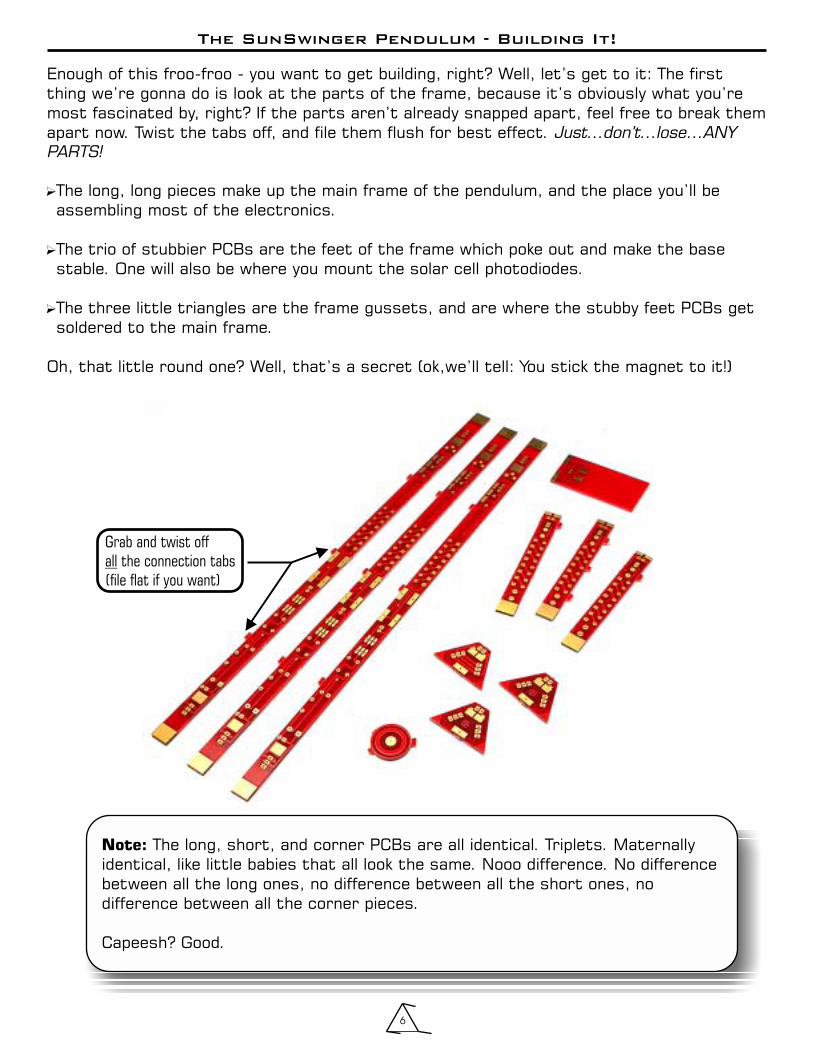
Note: The long, short, and corner PCBs are all identical. Triplets. Maternallyidentical, like little babies that all look the same. Nooo difference. No differencebetween all the long ones, no difference between all the short ones, nodifference between all the corner pieces.
Capeesh? Good.
The SunSwinger Pendulum - Building It!
6
Enough of this froo-froo - you want to get building, right? Well, let’s get to it: The firstthing we’re gonna do is look at the parts of the frame, because it’s obviously what you’remost fascinated by, right? If the parts aren’t already snapped apart, feel free to break themapart now. Twist the tabs off, and file them flush for best effect.
The long, long pieces make up the main frame of the pendulum, and the place you’ll beassembling most of the electronics.
The trio of stubbier PCBs are the feet of the frame which poke out and make the basestable. One will also be where you mount the solar cell photodiodes.
The three little triangles are the frame gussets, and are where the stubby feet PCBs getsoldered to the main frame.
Oh, that little round one? Well, that’s a secret (ok,we’ll tell: You stick the magnet to it!)
Just...don’t...lose...ANY
PARTS!
�
�
�
Grab and twist off
the connection tabs
(file flat if you want)
all
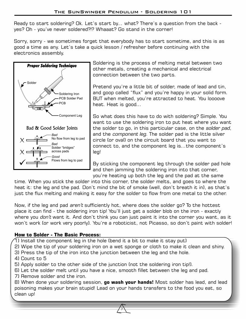
Soldering is the process of melting metal between twoother metals, creating a mechanical and electricalconnection between the two parts.
Pretend you’re a little bit of solder, made of lead and tin,and goop called “flux” and you’re happy in your solid form.BUT when melted, you’re attracted to heat. You looooveheat. Heat is good...
So what does this have to do with soldering? Simple. Youwant to use the soldering iron to put heat where you wantthe solder to go, in this particular case, on the ,and the The solder pad is the little silvercircle (or oval) on the circuit board that you want toconnect to, and the component leg is...the component’sleg!
By sticking the component leg through the solder pad holeand then jamming the soldering iron into that corner,you’re heating up both the leg and the pad at the same
time. When you stick the solder into this corner, the solder melts, and goes to where theheat it: the leg and the pad. Don’t mind the bit of smoke (well, don’t breath it in), as that’sjust the flux melting and making it easy for the solder to flow from one metal to the other.
Now, if the leg and pad sufficiently hot, where does the solder go? To the hottestplace it can find - the soldering iron tip! You’ll just get a solder blob on the iron - exactlywhere you want it. And don’t think you can just paint it into the corner you want, as itwon’t work (or work very poorly). You’re a roboticist, not Picasso, so don’t paint with solder!
1) Install the component leg in the hole (bend it a bit to make it stay put)2) Wipe the tip of your soldering iron on a wet sponge or cloth to make it clean and shiny.3) Press the tip of the iron into the junction between the leg and the hole.4) Count to 55) Apply solder to the other side of the junction (not the soldering iron tip!).6) Let the solder melt until you have a nice, smooth fillet between the leg and pad.7) Remove solder and the iron.8) When done your soldering session, Most solder has lead, and leadpoisoning makes your brain stupid! Lead on your hands transfers to the food you eat, soclean up!
solder padcomponent leg.
aren’t
don’t
How to Solder - The Basic Process:
go wash your hands!
The SunSwinger Pendulum - Soldering 101
7
Ready to start soldering? Ok. Let’s start by... what? There’s a question from the back -yes? Oh - you’ve never soldered?!? Whaaat? Go stand in the corner!
Sorry, sorry - we sometimes forget that everybody has to start sometime, and this is asgood a time as any. Let’s take a quick lesson / refresher before continuing with theelectronics assembly.
Proper Soldering Technique
Solder
Soldering Iron
PCB Solder Pad
PCB
Component Leg
Bad
No flow from leg to pad
Good
Flows from leg to pad
Bad
Solder “bridges”across pads
Bad & Good Solder Joints
X
X
�
i
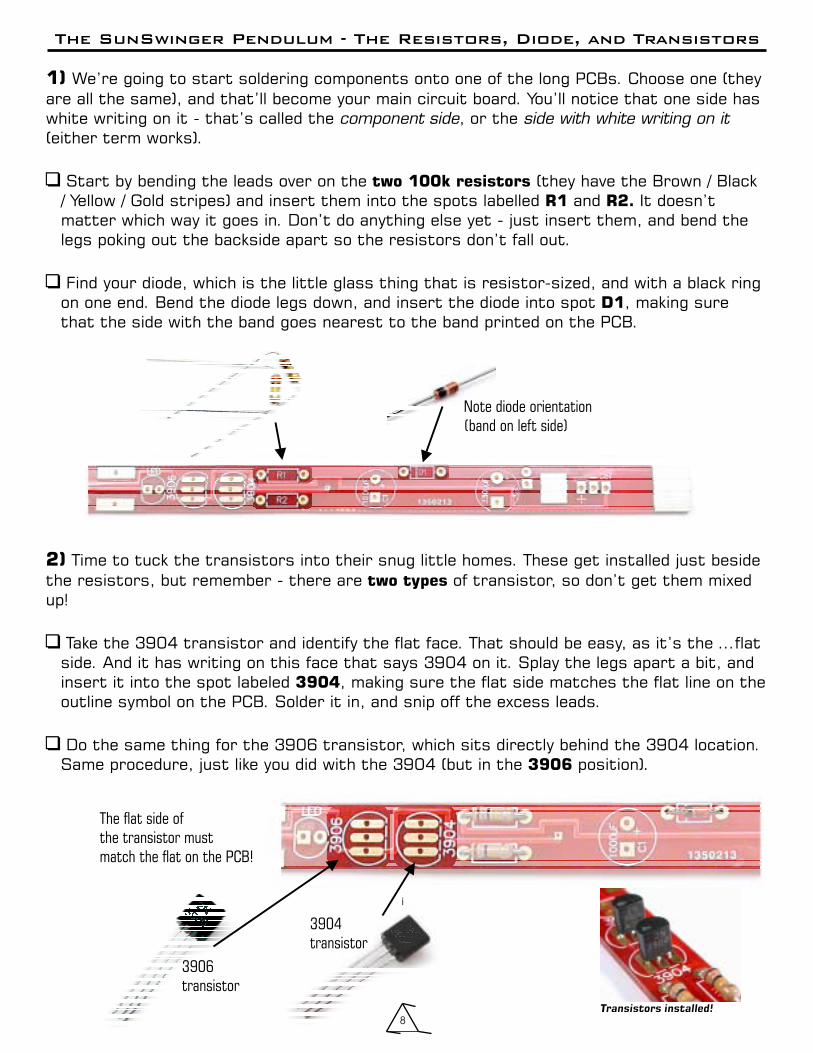
1) We’re going to start soldering components onto one of the long PCBs. Choose one (theyare all the same), and that’ll become your main circuit board. You’ll notice that one side haswhite writing on it - that’s called the , or the(either term works).
Start by bending the leads over on the (they have the Brown / Black/ Yellow / Gold stripes) and insert them into the spots labelled and It doesn’tmatter which way it goes in. Don’t do anything else yet - just insert them, and bend thelegs poking out the backside apart so the resistors don’t fall out.
Find your diode, which is the little glass thing that is resistor-sized, and with a black ringon one end. Bend the diode legs down, and insert the diode into spot , making surethat the side with the band goes nearest to the band printed on the PCB.
component side side with white writing on it
�
�
two 100k resistors
R1 R2.
D1
The SunSwinger Pendulum - The Resistors, Diode, and Transistors
Note diode orientation
(band on left side)
2) Time to tuck the transistors into their snug little homes. These get installed just besidethe resistors, but remember - there are of transistor, so don’t get them mixedup!
Take the 3904 transistor and identify the flat face. That should be easy, as it’s the ...flatside. And it has writing on this face that says 3904 on it. Splay the legs apart a bit, andinsert it into the spot labeled , making sure the flat side matches the flat line on theoutline symbol on the PCB. Solder it in, and snip off the excess leads.
Do the same thing for the 3906 transistor, which sits directly behind the 3904 location.Same procedure, just like you did with the 3904 (but in the position).
two types
3904
3906
�
�
The flat side of
the transistor must
match the flat on the PCB!
3904
transistor
3906
transistor
Transistors installed!8
The SunSwinger Pendulum - The Capacitors
9
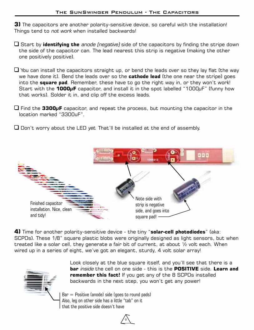
3) The capacitors are another polarity-sensitive device, so careful with the installation!Things tend to when installed backwards!
Start by side of the capacitors by finding the stripe downthe side of the capacitor can. The lead nearest this strip is negative (making the otherone positively positive).
You can install the capacitors straight up, or bend the leads over so they lay flat (the waywe have done it). Bend the leads over so the (the one near the stripe) goesinto the . Remember, these have to go the right way in, or they won’t work!Start with the capacitor, and install it in the spot labelled “1000µF” (funny howthat works). Solder it in, and clip off the excess leads.
Find the capacitor, and repeat the process, but mounting the capacitor in thelocation marked “3300uF”.
Don’t worry about the LED . That’ll be installed at the end of assembly.
not work
(negative)
yet
�
�
�
�
identifying the
cathode lead
square pad
1000µF
3300µF
anode
Note side with
strip is negative
side, and goes into
square pad!
Finished capacitor
installation. Nice, clean
and tidy!
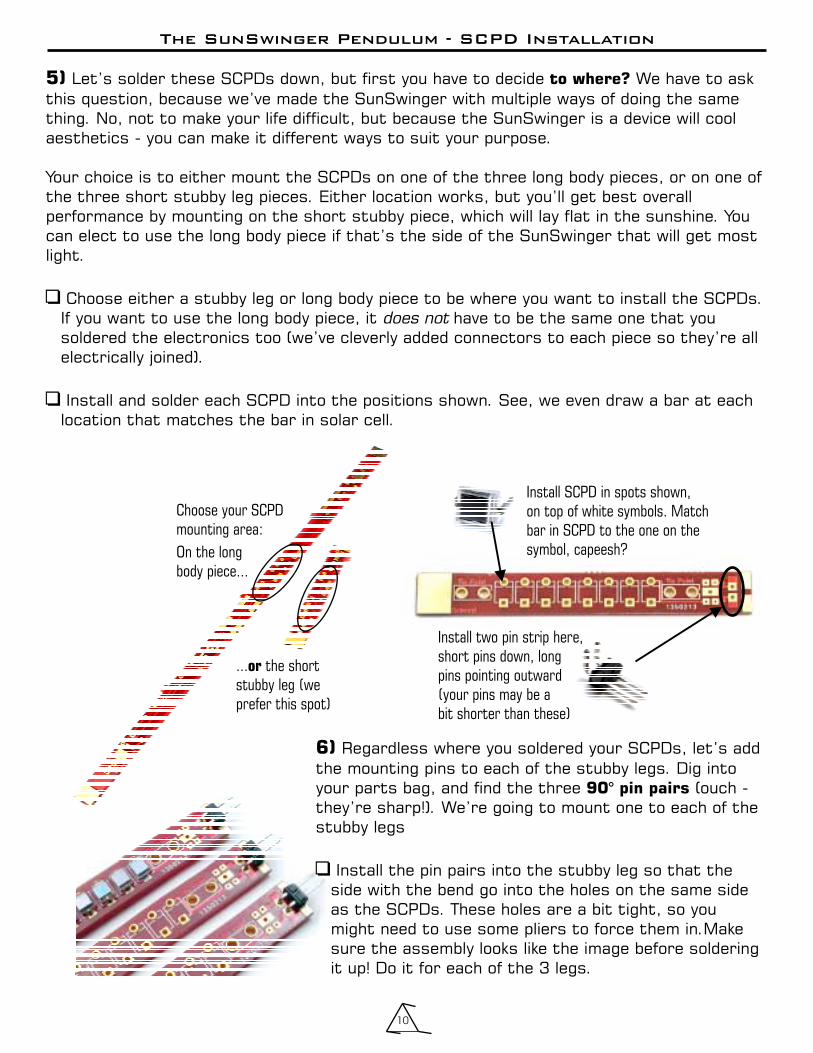
4) Time for another polarity-sensitive device - the tiny “ ” (aka:SCPDs). These 1/8” square plastic blobs were originally designed as light sensors, but whentreated like a solar cell, they generate a fair bit of current, at about ½ volt each. Whenwired up in a series of eight, we’ve got an elegant, sturdy, 4 volt solar array!
Look closely at the blue square itself, and you’ll see that there is athe cell on one side - this is the side.
If you get any of the 8 SCPDs installedbackwards in the next step, you won’t get any power!
solar-cell photodiodes
bar POSITIVE Learn and
remember this fact!
inside
Bar = Positive (anode) side (goes to round pads)
Also, leg on other side has a little “tab” on it
that the positive side doesn’t have
The SunSwinger Pendulum - SCPD Installation
10
5) Let’s solder these SCPDs down, but first you have to decide We have to askthis question, because we’ve made the SunSwinger with multiple ways of doing the samething. No, not to make your life difficult, but because the SunSwinger is a device will coolaesthetics - you can make it different ways to suit your purpose.
Your choice is to either mount the SCPDs on one of the three long body pieces, or on one ofthe three short stubby leg pieces. Either location works, but you’ll get best overallperformance by mounting on the short stubby piece, which will lay flat in the sunshine. Youcan elect to use the long body piece if that’s the side of the SunSwinger that will get mostlight.
Choose either a stubby leg or long body piece to be where you want to install the SCPDs.If you want to use the long body piece, it have to be the same one that yousoldered the electronics too (we’ve cleverly added connectors to each piece so they’re allelectrically joined).
Install and solder each SCPD into the positions shown. See, we even draw a bar at eachlocation that matches the bar in solar cell.
to where?
�
�
does not
Choose your SCPD
mounting area:
On the long
body piece...
... the short
stubby leg (we
prefer this spot)
or
Install SCPD in spots shown,
on top of white symbols. Match
bar in SCPD to the one on the
symbol, capeesh?
6) Regardless where you soldered your SCPDs, let’s addthe mounting pins to each of the stubby legs. Dig intoyour parts bag, and find the three (ouch -they’re sharp!). We’re going to mount one to each of thestubby legs
Install the pin pairs into the stubby leg so that theside with the bend go into the holes on the same sideas the SCPDs. These holes are a bit tight, so youmight need to use some pliers to force them in.Makesure the assembly looks like the image before solderingit up! Do it for each of the 3 legs.
90° pin pairs
�
Install two pin strip here,
short pins down, long
pins pointing outward
(your pins may be a
bit shorter than these)

The SunSwinger Pendulum - Gussets and Frame Assembly
11
Choose one side
or the other for all three gussets, and
solder in the 3-pin strips
Finished gusset pin installation
8) Let’s get this frame together, shall we? Time to take these pieces, and ...piece themtogether! Decide if you want the component side (with the white writing) or solder sidefacing out on your SunSwinger, and be consistent when soldering them together. This is apurely aesthetic decision, so do what you think looks best - it doesn’t affect the circuitry.
Choose what side of the long body pieces you want facing in or out, and be consistentbetween all of them (no effect, but looks better). into one of the
Make sure the gussets all face the same direction. If you have to, use sometape to hold the pieces together while you solder them.
We bet you know what’s coming now:Yup - solder on the remaining long bodypieces to the gussets so all threegussets and three body pieces are allsoldered together. Your Sun Swingerframe is taking shape!
�
�
Insert two gussets long
body pieces.
7) While we’re dealing with those sharp 90° pokey bits, let’s keep going and prepare thetriangular corner gussets with two triple-pin 90 . These will mechanically andelectrically join all the long and stubby pieces together. If you haven’t already done so,file/sand down the nubs off these gussets to make them fit together better. Just like withthe previous step, into Repeat it for each of thethree gussets, then take a break and eat a cookie. You’ve worked hard - you deserve it.
We found working on a piece of corrugated cardboard quite useful during this step.Put the gusset down, and press the pin strip through the holes into the cardboard. It holdseverything in place while you solder the pins in (but from the top-side). - pins aredang
The labled side of the gusset is the side the get solderedto. You can solder the triple-pin to side of the gusset (from the rear looks neater,but we’re showing them on the front for clarity), but be consistent and make the gussetsall the same way. Make sure the is soldered to the gusset!
install two 3-pin strips each gusset.
Note:
Be careful
sharp!
Another Note: ‘SB’
either
bent pin side
stubby legs
° strips
We have our
electronics facing
inward, but you can
flip it over if you want!
All corner gussets
are soldered in
same face-up (’SB’
side is going to
be the front)
The SunSwinger Pendulum - Stubby PCB Feet
12
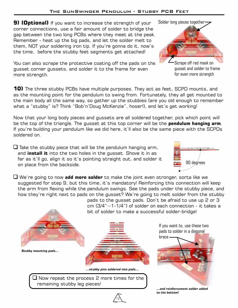
9) (Optional) If you want to increase the strength of yourcorner connections, use a fair amount of solder to bridge thegap between the two long PCBs where they meet at the peak.Remember - heat up the big pads, and let the solder melt tothem, NOT your soldering iron tip. If you’re gonna do it, now’sthe time, before the stubby feet segments get attached!
You can also scrape the protective coating off the pads on thegusset corner gussets, and solder it to the frame for evenmore strength.
10) The three stubby PCBs have multiple purposes. They act as feet, SCPD mounts, andas the mounting point for the pendulum to swing from. Fortunately, they all get mounted tothe main body all the same way, so gather up the stubbies (are you old enough to rememberwhat a “stubby” is? Think “Bob’n’Doug McKenzie”, hoser!), and let’s get working!
Now that your long body pieces and gussets are all soldered together, pick which point willbe the top of the triangle. The gusset at this top corner will be the .If you’re building your pendulum like we did here, it’ll also be the same piece with the SCPDssoldered on.
Take the stubby piece that will be the pendulum hanging arm,and into the two holes in the gusset. Shove it in asfar as it’ll go, align it so it’s pointing straight out, and solder iton place from the backside.
We’re going to now to make the joint even stronger, sorta like wesuggested for step 9, but this time, it’s mandatory! Reinforcing this connection will keepthe arm from flexing while the pendulum swings. See the pads under the stubby piece, andhow they’re right next to pads on the gusset? We’re going to melt solder from the stubby
pads to the gusset pads. Don’t be afraid to use up 2 or 3cm (3/4”~1-1/4”) of solder on each connection - it takes abit of solder to make a successful solder-bridge!
pendulum hanging arm
install it
add more solder
�
�
Solder long pieces together
Scrape off red mask on
gusset and solder to frame
for even more strength
Stubby mounting pads...
...stubby pins soldered into pads...
...and reinforcement solder added
to the bottom!
90 degrees
� Now repeat the process 2 more times for theremaining stubby leg pieces!
If you want to, use these two
pads to solder in a diagonal
brace

The SunSwinger Pendulum - The Stubby Feet Booties
13
11) Now it’s time to put some silicone rubber booties on the stubby feet. Yup, booties.They are not “anti-water”booties, they are “anti-walking” booties. Yes, we know howstrange that sounds, but it’s true. If you don’t put these booties on your SunSwinger, it’lltend to “walk” across your table when in full swing. We’ve seen enough of our ownSunSwingers fall off a window-sill because each swing of the pendulum makes the wholething move a bit. Pendulum walking machines have been built by other people,but for project, walking is bad!
Take the silicone tubing out of the kit, and . We’re going tostretch each one of these over the ends of the two stubby pieces.
this
� cut it in half
� Moisten the tip of your needle-nose pliers (don’t lick it -yuck!) and . jaws so youslip the pliers onto the end of one of the bottom stubbypieces.
slide the tubing on pry openGently
� the pliers over the edge of the stubby, but don’tgo crazy - you can snap the silicone tubing in half. If youdo, you’ll have to cut your remaining half in half again, andtry it again (but with more care).
Stretch
� When the tubing is in position, 1/4 turn.This makes removing the pliers while leaving the tubing inplace easier.
turn your pliers
much
� See? All done. Now do it again on the remaining stubbyfoot.
The SunSwinger Pendulum - The Coil Platform and Coil
14
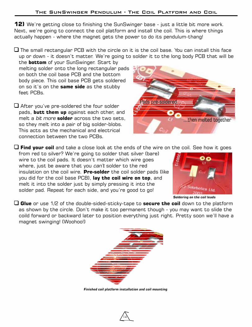
12) We’re getting close to finishing the SunSwinger base - just a little bit more work.Next, we’re going to connect the coil platform and install the coil. This is where thingsactually happen - where the magnet gets the power to do its pendulum-thang!
The small rectangular PCB with the circle on it is the coil base. You can install this faceup or down - it doesn’t matter. We’re going to solder it to the long body PCB that will bethe of your SunSwinger. Start bymelting solder onto the long rectangular padson both the coil base PCB and the bottombody piece. This coil base PCB gets solderedon so it’s on the as the stubbyfeet PCBs.
After you’ve pre-soldered the four solderpads, against each other, andmelt a across the two sets,so they melt into a pair of big solder-blobs.This acts as the mechanical and electricalconnection between the two PCBs.
�
�
bottom
same side
butt them up
solderbit more
Pads pre-soldered...
...then melted together
�
�
and take a close look at the ends of the wire on the coil. See how it goesfrom red to silver? We’re going to solder that silver (bare)wire to the coil pads. It doesn’t matter which wire goeswhere, just be aware that you solder to the redinsulation on the coil wire. the coil solder pads (likeyou did for the coil base PCB), , andmelt it into the solder just by simply pressing it into thesolder pad. Repeat for each side, and you’re good to go!
or use 1/2 of the double-sided-sticky-tape to down to the platformas shown by the circle. Don’t make it too permanent though - you may want to slide thecoild forward or backward later to position everything just right. Pretty soon we’ll have amagnet swinging! (Woohoo!)
Find your coil
Pre-solder
lay the coil wire on top
Glue secure the coil
can’t
Soldering on the coil leads
Finished coil platform installation and coil mounting

The SunSwinger Pendulum - The Magnet
15
13) It’s magnet-time! A coil of wire and a magnet are the essentials of an electric motor,and we’re about to start playing with the physical interactions between them. This is prettyneat - have fun with this step!
. Can’t find it? It’s most likely either still wrapped up in several layers ofbubble-wrap, or stuck to a metallic object. These sneaky things will often attach to ametal chair’s leg instead of falling directly to the floor, so if it’s missing, inspect all nearbymetal objects!
Now that you have your magnet, take yourSunSwinger and put it under Put the
, off to one side a bit .If it’s on right-side up, it’ll
vibrate and shimmy towards the middle of the coil. Ifit’s upside down, the coil will go “Ptwoo!” and spit itoff. Having the magnet push against the coil is bad, asover time, the repeated “pushes” tend to weaken themagnet, making performance worse. Having themagnet pull against the coil reinforces it, keeping itstrong.
what side of the magnet is the top by using the dot on one side of the magnet asan indicator. Just remember “dot UP” or “dot DOWN” when you get thevibrate/pulse/shimmy toward the coil middle. That’ll be your magnet’s “top”.
�
�
�
Find your magnet
bright light.
magnet on the coil You want it
to jump to the middle.
Note
14) Now that we know which side of the magnet is right-side up, we’re going to mount iton the magnet mount.
with the hole in the middle - this is ourmagnet mount. Strip off some (or all) the insulation off the short pieceof in the kit, and nice, thick, short chunk of wire in thekit into the pad hole. If you lost the wire, use a resistoror diode clipping instead - no big deal. We don’t want the wire to pokethrough the bottom - this is where we’ll mount the magnet. If the wire
poke through the bottom, snip it off as flush as you can.
Take some double-sided sticky-tape (let’s call it DSST, ok?) left overfrom the coil mounting step and “top” to the
around the top of the clipping, so it almost makes acomplete circle. Don’t trim anything off yet, as you may need some ofthe extra length to fine-tune how high the magnet hangs over the coil inthe next step.
�
�
�
Find the round, red PCB
thick solid wire
and solder it
stick the magnet bottom
of the mount.
Bend a little hook
does
If needed, flip magnet so
it moves toward middle
The SunSwinger Pendulum - Hanging the Magnet
16
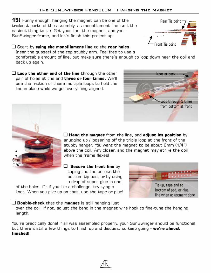
15) Funny enough, hanging the magnet can be one of thetrickiest parts of the assembly, as monofilament line isn’t theeasiest thing to tie. Get your line, the magnet, and yourSunSwinger frame, and let’s finish this project up!
Start by to the(near the gusset) of the top stubby arm. Feel free to use acomfortable amount of line, but make sure there’s enough to loop down near the coil andback up again.
through the otherpair of holes at the end We’lluse the friction of these multiple loops to hold theline in place while we get everything aligned.
�
�
tying the monofilament line rear holes
Loop the other end of the line
three or four times.
Rear Tie point
Front Tie point
Knot at back
Loop through 3 times
from bottom at front
�
�
�
from the line, and bysnugging up / loosening off the triple loop at the front of thestubby hanger. You want the magnet to be about 6mm (1/4”)above the coil. Any closer, and the magnet may strike the coilwhen the frame flexes!
bytaping the line across thebottom tip pad, or by usinga drop of super-glue in one
of the holes. Or if you like a challenge, try tying aknot. When you give up on that, use the tape or glue!
that the is still hanging justover the coil. If not, adjust the bend in the magnet wire hook to fine-tune the hanginglength.
You’re practically done! If all was assembled properly, your SunSwinger should be functional,but there’s still a few things to finish up and discuss, so keep going -
Hang the magnet adjust its position
Secure the front line
Double-check magnet
we’re almost
finished!
6mm
(1/4”)
Tie up, tape end to
bottom of pad, or glue
line when adjustment done

The SunSwinger Pendulum - The LED
17
16) The LED isn’t to the operation of the circuit, but there is a two-fold benefitto including it. The first is that it “snubs” the back-EMF pulse of the coil. Any coil that issuddenly turned off sends a considerable reverse-pulse of power that can damageelectronics. The LED (acting as a diode) keeps the pulse from becoming a problem. Secondly,the LED , and as we all know, blinky lights are a good thing... By watching the LED,you should be able to determine what the circuit is doing, especially in bright light. Rapidflickering indicates that it’s “on the edge” and ready to trigger. No flickering means, well,something’s wrong, and it’s time to check your soldering.
Here are your LED mounting options (choose ):
If you want your LED front and center by the coil, you can usethe mounting pads on the coil-mounting PCB above the “Coil”label. Since this pad can be installed upside down, there isn’ta orientation symbol at this location. You’ll have to follow theline in the LED location on the long bodyPCB to the appropriate pad on the coil mount - this will be the
(shorter lead).
essential
blinks
one
from the square pad
cathode
�
�
shorter
lead square
You can mount your LED you see an LED symbol / label on any of the three longbody pieces (in the position marked ‘LED’) - even on the PCBs that don’t have theelectronics. You can install the LED on either side side of the PCB, as long as the
(the ‘cathode’) is soldered to the pad.
anywhere
Follow square pad to coil
PCB - this is where shorter
(cathode) lead of LED is soldered
...or behind it
on the other
side of the
PCB.
Install the LED at
any LED symbol
location, right
on top of the
symbol...
OR
There! You’re officially finished your SunSwinger Pendulum! But (if for some bizarre,unimaginable reason) your SunSwinger isn’t working, take a look at the troubleshootingpage...
What do you it doesn’t work? Did you swing a purple onion over your head under thelight of a full moon chanting “Wagga Wagga Wooooo”? That didn’t work either, hmmm? Firstand foremost - Fluorescent lights don’t work very well,but natural light (even indirect light from a window) and practically any regular light bulb20cm (7”) above will be fine. Flashlights will barely to the job.
The two transistor look awfully a lot alike, so make sure you’re not mixing up a ‘3904’with a ‘3906’. And they have to be installed so their shape matches the shape on thecircuit board.
Unlike the resistors, the diode has to go in the right-way around, with the black bandon the diode matching the position shown by the band on the symbol on the PCB.
The two electrolytic capacitors also have to be installed the right way, with the leadnearest the stripe going into the pad.
Still can’t see anything wrong? Check the solar cell photo-diodes (SCPDs).First check to see that they are soldered in the right way around. Even if just one
is in backwards, it will stop any power from flowing. Make surethe bar inside the SCPD matches the bar position printed onthe circuit board.
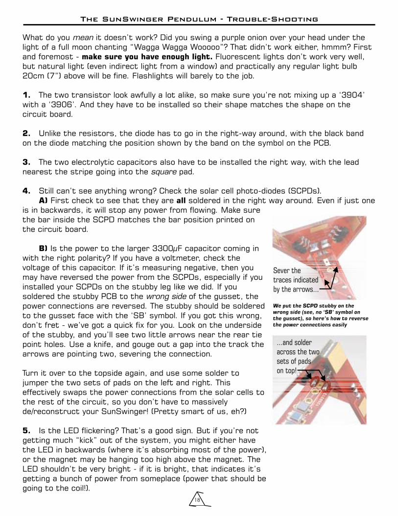
Is the power to the larger 3300µF capacitor coming inwith the right polarity? If you have a voltmeter, check thevoltage of this capacitor. If it’s measuring negative, then youmay have reversed the power from the SCPDs, especially if youinstalled your SCPDs on the stubby leg like we did. If yousoldered the stubby PCB to the of the gusset, thepower connections are reversed. The stubby should be solderedto the gusset face with the ‘SB’ symbol. If you got this wrong,don’t fret - we’ve got a quick fix for you. Look on the undersideof the stubby, and you’ll see two little arrows near the rear tiepoint holes. Use a knife, and gouge out a gap into the track thearrows are pointing two, severing the connection.
Turn it over to the topside again, and use some solder tojumper the two sets of pads on the left and right. Thiseffectively swaps the power connections from the solar cells tothe rest of the circuit, so you don’t have to massivelyde/reconstruct your SunSwinger! (Pretty smart of us, eh?)
Is the LED flickering? That’s a good sign. But if you’re notgetting much “kick” out of the system, you might either havethe LED in backwards (where it’s absorbing most of the power),or the magnet may be hanging too high above the magnet. TheLED shouldn’t be very bright - if it is bright, that indicates it’sgetting a bunch of power from someplace (power that should begoing to the coil!).
mean
square
wrong side
make sure you have enough light.
1.
2.
3.
4.
A) all
B)
5.
The SunSwinger Pendulum - Trouble-Shooting
18
...and solder
across the two
sets of pads
on top!
We put the SCPD stubby on the
wrong side (see, no ‘SB’ symbol on
the gusset), so here’s how to reverse
the power connections easily
Sever the
traces indicated
by the arrows...
The SunSwinger Pendulum - Add-ons
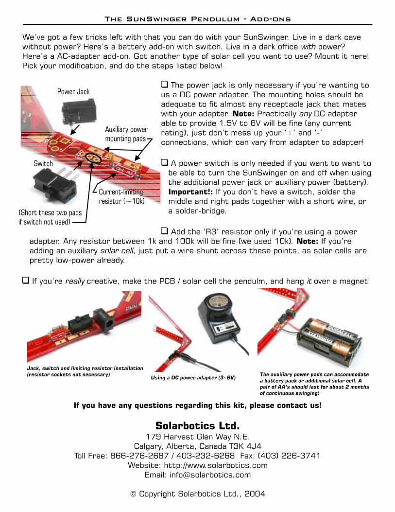
We’ve got a few tricks left with that you can do with your SunSwinger. Live in a dark cavewithout power? Here’s a battery add-on with switch. Live in a dark office power?Here’s a AC-adapter add-on. Got another type of solar cell you want to use? Mount it here!Pick your modification, and do the steps listed below!
with
�
�
�
The power jack is only necessary if you’re wanting tous a DC power adapter. The mounting holes should beadequate to fit almost any receptacle jack that mateswith your adapter. Practically DC adapterable to provide 1.5V to 6V will be fine (any currentrating), just don’t mess up your ‘+’ and ‘-’connections, which can vary from adapter to adapter!
A power switch is only needed if you want to want tobe able to turn the SunSwinger on and off when usingthe additional power jack or auxiliary power (battery).
If you don’t have a switch, solder themiddle and right pads together with a short wire, ora solder-bridge.
Add the ‘R3’ resistor only if you’re using a power
Note:
Important!:
any
adapter. Any resistor between 1k and 100k will be fine (we used 10k). If you’readding an auxiliary , just put a wire shunt across these points, as solar cells arepretty low-power already.
If you’re creative, make the PCB / solar cell the pendulm, and hang over a magnet!
Note:
solar cell
really it�
Power Jack
Auxiliary power
mounting pads
Current-limiting
resistor (~10k)
Switch
(Short these two pads
if switch not used)
Jack, switch and limiting resistor installation
(resistor sockets not necessary)Using a DC power adapter (3~6V)
The auxiliary power pads can accommodate
a battery pack or additional solar cell. A
pair of AA’s should last for about 2 months
of continuous swinging!
If you have any questions regarding this kit, please contact us!
Solarbotics Ltd.179 Harvest Glen Way N.E.
Calgary, Alberta, Canada T3K 4J4Toll Free: 866-276-2687 / 403-232-6268 Fax: (403) 226-3741
Website: http://www.solarbotics.comEmail: [email protected]
© Copyright Solarbotics Ltd., 2004