Embed Size (px)
Citation preview
ARTICLE IN PRESS
Journal of Wind Engineering
and Industrial Aerodynamics 96 (2008) 1164–1184
0167-6105/$ -
doi:10.1016/j
�CorrespoE-mail ad
1Current a
AB, Canada
www.elsevier.com/locate/jweia
The suppression of periodic vortex shedding from arotating circular cylinder
Sharul Sham Dol1, Gregory A. Kopp�, Robert J. Martinuzzi1
Faculty of Engineering, University of Western Ontario, London, ON, Canada N6A 5B9
Available online 27 July 2007
Abstract
An experimental study of the turbulent near wake of a rotating circular cylinder was made at a
Reynolds number of 9000 for velocity ratios, l ¼ OD/(2UN), between 0 and 2.7. Analysis of hot-wire
anemometry data from the near wake indicates that the periodic vortex shedding is suppressed for
lX�2.0. It was also observed that the Strouhal number and convection speed of the vortices
increases with the velocity ratio up to suppression of the vortex street. The spacing ratio of the
vortices remains constant while there is a vortex street. After suppression of the street, it is observed
that the convection speeds of the two rows of vortices differ while the spacing ratio diminishes. These
results are consistent with an earlier stability analysis taking into account the inequality of the two
shear layers. In addition, increased inequality of the two separated shear layers leads to weaker
vortices in the near wake region.
r 2007 Elsevier Ltd. All rights reserved.
Keywords: Circular cylinder; Strouhal number; Vortex shedding; Vortex dynamics
1. Introduction
1.1. Vortex shedding
Periodic vortex shedding is a phenomenon of great practical importance in manyapplications because of the significant fluctuating lift and drag forces or enhanced mixing
see front matter r 2007 Elsevier Ltd. All rights reserved.
.jweia.2007.06.038
nding author. Tel.: +1 519 6613338; fax: +1519 6613339.
dress: [email protected] (G.A. Kopp).
ddress: Department of Mechanical and Manufacturing Engineering, University of Calgary, Calgary,
T2N 1N4.
ARTICLE IN PRESSS.S. Dol et al. / J. Wind Eng. Ind. Aerodyn. 96 (2008) 1164–1184 1165
which results. Many factors are known to affect vortex shedding including splitter platesand base bleed, both of which suppress shedding (Roshko, 1954; Gerrard, 1966), endplates, which affect the three dimensionality of the shed vortices (Stansby, 1974;Williamson, 1996), blockage (Shair et al., 1963), and others. Zdravkovich (1997, 2003)and Williamson (1996) provide recent and comprehensive reviews of flow around circularcylinders and the Karman vortex street.
Asymmetry of the flow around an otherwise symmetric bluff body (such as a shear flowimpinging on a circular cylinder or flow around a rotating circular cylinder) or flow aroundasymmetric bluff bodies, such as bridge decks, are also known to affect, or even suppress,periodic vortex shedding. Bailey et al. (2003) studied the flow around a square cylindernear a wall and found that suppression of a periodic vortex street occurred once thecylinder was sufficiently close to the wall. They speculated that the suppression was not dueto the cancellation of vorticity in the separated shear layer closest to the wall by wallvorticity (which is of opposite sign) but rather to the reattachment of the shear layer to thecylinder surface so that its strength was significantly different from the other separatedshear layer. In other words, an alternating, periodic (or Karman) vortex street did notresult since the two shear layers were too different to couple. Bailey et al. (2003) alsoshowed this result theoretically.
The formation of a vortex street is considered to be the result of a coupling ofinstabilities between two (separated) shear layers, or vortex sheets, which have rolled up.An excellent example of this can be seen in the experimental work of Huang and Keffer(1996) who studied the wake of a porous mesh strip, although this idea has existed forsome time and led to the discrete vortex method (e.g., Abernathy and Kronauer, 1961). Invon Karman’s famous stability analysis (Karman, 1912), where he assumed that eachseparated shear layer can be modeled as an infinite row of co-rotating vortices and that thetwo rows (of opposite signed vorticity) are of equal strength, only a single stablearrangement could be found with staggered, opposing rows of vortices with a spacingratio, b/a ¼ 0.281, where b is the vertical spacing and a is the streamwise spacing. While theproblems with this result are well known, most notably that the spacing ratio of 0.281 isnot observed in practice, von Karman’s approach has still been shown to be useful morerecently (Kochin et al., 1964; Aref, 1995). Bailey (2001) and Bailey et al. (2003) showedthat for a coordinate system moving at the convective speed of two rows of vortices withunequal strengths, G1 and G2, a stable arrangement with spacing ratio 0.281 existed for arange of circulation ratios,
0:38oG1
G2o2:62. (1)
For circulation ratios outside of this range, no stable configuration was found and theperiodic vortex street was suppressed. Since the spacing ratio of 0.281 is not observed inpractice for equal circulations, we would not expect to see this value for unequalcirculations. Rather, the implication is that b/a should remain constant for variable vortexstrengths. Bailey et al.’s (2003) analysis of the experimental data confirmed this hypothesis.However, the flow near the wall always raises doubts as to the interpretation of the databecause of the presence of wall vorticity. Nevertheless, this result suggests a practicalmethod for the control of vortex shedding where asymmetry in the flow field can bedeliberately induced by the bluff body geometry. The current work is motivated by thetheory of Bailey et al. (2003) but here we examine the flow around a rotating circular
ARTICLE IN PRESSS.S. Dol et al. / J. Wind Eng. Ind. Aerodyn. 96 (2008) 1164–11841166
cylinder, a flow in which it is much more straightforward to control the strength of theseparated shear layers with no additional vorticity present.
1.2. Flow past a rotating cylinder
The flow past a rotating cylinder is more complex than that around a stationarycylinder. Rotation of the cylinder substantially alters the behavior of the wake with respectto the stationary case due to the modification of the boundary layers (prior to separation)and the separated shear layers. The flow field depends primarily on two parameters. Thefirst is the Reynolds number, Re ¼ UND/u, where UN is the free stream velocity, D is thecylinder diameter, and u is the kinematic viscosity of the fluid. The second is the velocityratio, l ¼ UP/UN where UP ¼ OD/2 is the surface speed of the cylinder and O is theangular speed of the rotation. Swanson (1961) and Diaz et al. (1983) observed that there isdecay of the periodic vortex activity and an increase in the random modulation of theshedding process and that these are linked to the displacement of the stagnation point andto the thickening of the layer of rotating fluid near the cylinder surface. In addition, as thevelocity ratio increases, the mean velocity profile becomes increasingly asymmetricalas the lateral position of the maximum velocity is displaced in the direction consistent withthe sense of the cylinder rotation. Diaz et al. (1983) also found that at high-velocity ratios,the periodic vortex street is suppressed.Some of the most detailed work on this problem was done by Badr et al. (1990), who
investigated the unsteady flow past a rotating circular cylinder (experimentally andnumerically) for Reynolds numbers in the range 103pRep104 and velocity ratios,0.5plp3.0. The result shows that the conventional periodic vortex shedding is alteredsubstantially by the rotation. A thorough literature survey reveals, however, that there isno published account of shear layer or vortex strengths, although Prandtl (1961) did
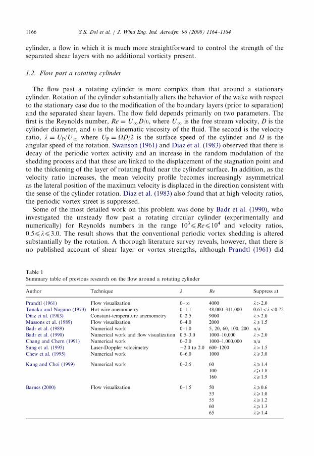
Table 1
Summary table of previous research on the flow around a rotating cylinder
Author Technique l Re Suppress at
Prandtl (1961) Flow visualization 0–N 4000 l42.0
Tanaka and Nagano (1973) Hot-wire anemometry 0–1.1 48,000–311,000 0.67olo0.72
Diaz et al. (1983) Constant-temperature anemometry 0–2.5 9000 l42.0
Massons et al. (1989) Flow visualization 0–4.0 2000 lX1.5
Badr et al. (1989) Numerical work 0–1.0 5, 20, 60, 100, 200 n/a
Badr et al. (1990) Numerical work and flow visualization 0.5–3.0 1000–10,000 l42.0
Chang and Chern (1991) Numerical work 0–2.0 1000–1,000,000 n/a
Sung et al. (1995) Laser-Doppler velocimetry �2.0 to 2.0 600–1200 l41.5
Chew et al. (1995) Numerical work 0–6.0 1000 lX3.0
Kang and Choi (1999) Numerical work 0–2.5 60 lX1.4
100 lX1.8
160 lX1.9
Barnes (2000) Flow visualization 0–1.5 50 lX0.6
53 lX1.0
55 lX1.2
60 lX1.3
65 lX1.4
ARTICLE IN PRESSS.S. Dol et al. / J. Wind Eng. Ind. Aerodyn. 96 (2008) 1164–1184 1167
examine the circulation in the start-up flow (see also Zdravkovich, 2003). Table 1summarizes the relevant parameters and techniques of previously published studies(Diaz et al., 1983; Badr et al., 1989, 1990; Prandtl, 1961; Tanaka and Nagano, 1973;Massons et al., 1989; Chang and Chern, 1991; Sung et al., 1995; Chew et al., 1995; Kangand Choi, 1999; Barnes, 2000) along with the observed velocity ratios at suppression.
Given the above discussion, the objective of the present research is to investigate thestrength of the shear layers and vortices of the periodic (Karman) vortex street asthe velocity ratio, l, is altered so that we could determine whether suppression of theperiodic street occurs due to inequality of the separated shear layers as postulated byBailey et al. (2003).
2. Experimental details
The experiments were performed at the Boundary Layer Wind Tunnel Laboratory(BLWTL) of the University of Western Ontario in a suction-type wind tunnel with a1500mm long working section and 450� 450mm2 cross section. The intake flow wasstraightened through a honeycomb and fine screen prior to entering a 7.4:1 contraction.Hot-wire anemometry (HWA) measurements across the test section showed a uniform freestream within 1.0% and a turbulence intensity of less than 1% (Bailey, 2001).
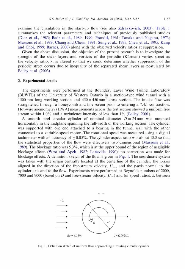
A smooth steel circular cylinder of nominal diameter D ¼ 24mm was mountedhorizontally in the midplane spanning the full-width of the working section. The cylinderwas supported with one end attached to a bearing in the tunnel wall with the otherconnected to a variable-speed motor. The rotational speed was measured using a digitaltachometer with an accuracy of 70.05%. The cylinder aspect ratio was about 18.8 so thatthe statistical properties of the flow were effectively two dimensional (Massons et al.,1989). The blockage ratio was 5.3%, which is at the upper bound of the region of negligibleblockage effects (West and Apelt, 1982; Laneville, 1990); no correction was made forblockage effects. A definition sketch of the flow is given in Fig. 1. The coordinate systemwas taken with the origin centrally located at the centerline of the cylinder, the x-axisaligned in the direction of the free-stream velocity, UN, and the y-axis normal to thecylinder axis and to the flow. Experiments were performed at Reynolds numbers of 2000,7000 and 9000 (based on D and free-stream velocity, UN) and for speed ratios, l, between
U
y
xD
� �
�
Re = U D/ = D/2U∞
∞
∞�
Fig. 1. Definition sketch of uniform flow approaching a rotating circular cylinder.
ARTICLE IN PRESSS.S. Dol et al. / J. Wind Eng. Ind. Aerodyn. 96 (2008) 1164–11841168
0 and 2.7. HWA and particle imaging velocimetry (PIV) results are reported forRe ¼ 9000, while the flow visualization was performed at Re ¼ 2000.The fluid motion behind the cylinder was visualized by using the smoke-wire technique.
Due to dispersion of smoke lines at high speeds, visualizations were limited to speeds ofless than 1.5m/s (i.e., Re ¼ 2000) in the present study. An electrically heated, twistedtungsten-nicrome wire, which was coated with low-viscosity oil (glycerine) was setupstream of the cylinder (x/DE�1.5). A high-intensity lamp was used for illuminating thesmoke to ensure that the smoke lines were clearly visible for photographic recording. Theinstantaneous smoke lines were recorded using a high-speed digital motion-picture camera(Red Lake Imaging) at 125 frames s. Individual frames are shown herein.The vortex shedding frequencies were determined from the velocity fluctuations in the
wake at x/D ¼ 3, using a single normal hot-wire connected to a DANTEC 90C10constant-temperature anemometry (CTA) system. Signals from the circuits were offset,amplified and low-pass filtered at half of the sampling rate. The sampling rate was 5000Hzfor 60 s. The resolution of the shedding frequency, obtained by using a standard fastFourier transformation (FFT) algorithm, was calculated to be 0.15Hz.A TSI PIV system was utilized to measure the instantaneous velocities in the x�y
(vertical) plane. Atomized vegetable oil was used for seeding particles. These wereilluminated by two Nd:YAG 400mJ/pulse lasers. A 1024� 1024 pixel charge-coupleddevice (CCD) camera was used to capture the images at a rate of 15 double framesper second. The camera was fitted with a lens (focal length range of 60mm) and theobject distance was adjusted to obtain a field-of-view of �5.5D� 5.5D. The TSIInsights software was used to analyze the captured images using the cross-correlationtechnique. The spatial resolution, using images of approximately 5.5D� 5.5D with32� 32 pixel interrogation areas was 0.131mm/pixel. An overlap of 50% of theinterrogation area was used together with a Gaussian window function to minimize theloss of pairs. The time delay between image pairs was between 80 and 160 ms in allthe experiments. Operating parameters for the PIV set-up and measurements can be foundin Dol (2004).The experimental uncertainties were calculated using the methods described in Coleman
and Steele (1989) with details in Dol (2004).
3. Flow visualization results
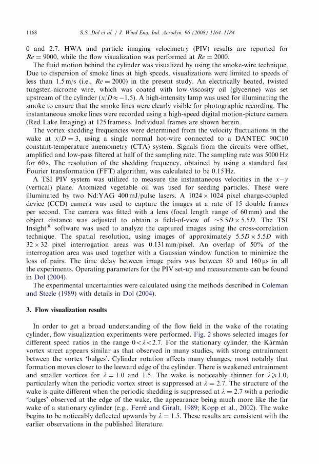
In order to get a broad understanding of the flow field in the wake of the rotatingcylinder, flow visualization experiments were performed. Fig. 2 shows selected images fordifferent speed ratios in the range 0olo2.7. For the stationary cylinder, the Karmanvortex street appears similar as that observed in many studies, with strong entrainmentbetween the vortex ‘bulges’. Cylinder rotation affects many changes, most notably thatformation moves closer to the leeward edge of the cylinder. There is weakened entrainmentand smaller vortices for l ¼ 1.0 and 1.5. The wake is noticeably thinner for lX1.0,particularly when the periodic vortex street is suppressed at l ¼ 2.7. The structure of thewake is quite different when the periodic shedding is suppressed at l ¼ 2.7 with a periodic‘bulges’ observed at the edge of the wake, the appearance being much more like the farwake of a stationary cylinder (e.g., Ferre and Giralt, 1989; Kopp et al., 2002). The wakebegins to be noticeably deflected upwards by l ¼ 1.5. These results are consistent with theearlier observations in the published literature.
ARTICLE IN PRESS
Fig. 2. Instantaneous smoke-wire flow visualizations: (a) l ¼ 0, (b) l ¼ 0.6, (c) l ¼ 1.0, (d) l ¼ 1.5, (e) l ¼ 2.0,
(f) l ¼ 2.7.
S.S. Dol et al. / J. Wind Eng. Ind. Aerodyn. 96 (2008) 1164–1184 1169
ARTICLE IN PRESSS.S. Dol et al. / J. Wind Eng. Ind. Aerodyn. 96 (2008) 1164–11841170
4. Hot-wire anemometry results
Auto-correlation functions of the velocity fluctuations, obtained using HWA, were usedto examine the periodic nature of the wake. The auto-correlation of a zero-mean signal,a(t), is evaluated as
raaðtÞ ¼aðtÞaðtþ tÞ
a2, (2)
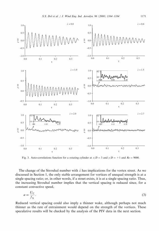
where t is a time lag and a2 is the variance of the signal. For this purpose, the normalizedauto-correlation functions of the stream-wise velocity fluctuations for Re ¼ 9000 andl ¼ 0, 0.6, 1.0, 1.5, 2.0 and 2.7 measured at x/D ¼ 3 and y/D ¼+1 are presented in Fig. 3.Plots at other Reynolds numbers can be found in Dol (2004). Regular oscillations exist forperipheral speeds up to the free-stream velocity, indicating that a well-defined Karmanvortex street characterizes the near-wake region for lp1.0. The slow but significant decayof the amplitude of the oscillations with increasing t indicates that the vortex sheddingprocess is not a strictly periodic process, but rather, is randomly modulated in frequencyand phase, as established by Budny et al. (1979). For l ¼ 0, the value of the Strouhalnumber associated with this characteristic frequency is about 0.19, which is in goodagreement with the well-known values for stationary circular cylinders at this Reynoldsnumber (Zdravkovich, 1997, 2003).These auto-correlation functions exhibit oscillation amplitudes that decrease as the
rotational velocity, UP, increases. The oscillatory component of these functions alsodecreases sharply for l41.0. From these results, it can be inferred that a regular periodicvortex shedding occurs for rotational speeds up to the speed of the free-stream; when therotational speed is greater than the speed of the free stream (l41), a significant disruptionoccurs, indicating significant changes in the shedding. Only weak periodicity can beobserved from the auto-correlation function for lX1.5. By l ¼ 2.7 the periodicity is gone,indicating the suppression of regular periodic vortex shedding. It is not clear whether thismeans that the vortex shedding frequency is increasingly less-well defined (i.e., the periodvaries significantly) or that the strength of the shed vortices decreases as the rotationalrates increases. This will be discussed in detail with the particle image velocimetry resultsbelow.It is also worth mentioning that these findings are consistent with those obtained by
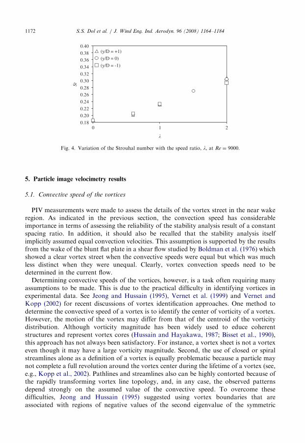
Diaz et al. (1983) and Massons et al. (1989), respectively, who concluded that theconventional Karman vortex shedding is significantly modified by rotation for lX1.5.Diaz et al. (1983) did mention that the decay of the periodic vortex activity and the increasein the random modulation of the shedding process are linked to the displacement of thestagnation point and to the thickening of the layer of rotating fluid near the cylindersurface. This apparently causes the stagnation point to move off of the surface of thecylinder and under different lateral velocity gradients in the regions above and below thecylinder, altering the vorticity generation mechanisms (Diaz et al., 1983).The variation of the Strouhal number with the velocity ratio is shown in Fig. 4. These
results are consistent with those presented by Diaz et al. (1983) and Massons et al. (1989).It was reported by Diaz et al. (1983) that for velocity ratio much in excess of 1.0, a specificStrouhal number could not be defined since the shedding process then becomes rapidlymore random and/or weaker so that no definite shedding frequency can be inferred fromthe auto-spectral results (see Dol, 2004 for details).
ARTICLE IN PRESS
-1.0
-0.5
0.0
� ��
0.5
1.0
0.0 0.1 0.2 0.3τ
-1.0
-0.5
0.0
� ��
0.5
1.0
0.0 0.1 0.2 0.3τ
-1.0
-0.5
0.0
� ��
0.5
1.0
0.0 0.1 0.2 0.3τ
-1.0
-0.5
0.0�
��
0.5
1.0
0.0 0.1 0.2 0.3τ
-1.0
-0.5
0.0
� ��
0.5
1.0
0.0 0.1 0.2 0.3τ
-0.5
0.0
� ��
0.5
1.0
0.0 0.1 0.2 0.3τ
� = 1.0
� = 2.0 � = 2.7
� = 1.5
� = 0.0 � = 0.6
Fig. 3. Auto-correlations function for a rotating cylinder at x/D ¼ 3 and y/D ¼+1 and Re ¼ 9000.
S.S. Dol et al. / J. Wind Eng. Ind. Aerodyn. 96 (2008) 1164–1184 1171
The change of the Strouhal number with l has implications for the vortex street. As wediscussed in Section 1, the only stable arrangement for vortices of unequal strength is at asingle spacing ratio; or, in other words, if a street exists, it is at a single spacing ratio. Thus,the increasing Strouhal number implies that the vertical spacing is reduced since, for aconstant convective speed,
a ¼UC
f S
. (3)
Reduced vertical spacing could also imply a thinner wake, although perhaps not muchthinner as the rate of entrainment would depend on the strength of the vortices. Thesespeculative results will be checked by the analysis of the PIV data in the next section.
ARTICLE IN PRESS
0.18
0.20
0.22
0.24
0.26
0.28
0.30
0.32
0.34
0.36
0.38
0.40
210
St
(y/D = +1)
(y/D = 0)
(y/D = -1)
�
Fig. 4. Variation of the Strouhal number with the speed ratio, l, at Re ¼ 9000.
S.S. Dol et al. / J. Wind Eng. Ind. Aerodyn. 96 (2008) 1164–11841172
5. Particle image velocimetry results
5.1. Convective speed of the vortices
PIV measurements were made to assess the details of the vortex street in the near wakeregion. As indicated in the previous section, the convection speed has considerableimportance in terms of assessing the reliability of the stability analysis result of a constantspacing ratio. In addition, it should also be recalled that the stability analysis itselfimplicitly assumed equal convection velocities. This assumption is supported by the resultsfrom the wake of the blunt flat plate in a shear flow studied by Boldman et al. (1976) whichshowed a clear vortex street when the convective speeds were equal but which was muchless distinct when they were unequal. Clearly, vortex convection speeds need to bedetermined in the current flow.Determining convective speeds of the vortices, however, is a task often requiring many
assumptions to be made. This is due to the practical difficulty in identifying vortices inexperimental data. See Jeong and Hussain (1995), Vernet et al. (1999) and Vernet andKopp (2002) for recent discussions of vortex identification approaches. One method todetermine the convective speed of a vortex is to identify the center of vorticity of a vortex.However, the motion of the vortex may differ from that of the centroid of the vorticitydistribution. Although vorticity magnitude has been widely used to educe coherentstructures and represent vortex cores (Hussain and Hayakawa, 1987; Bisset et al., 1990),this approach has not always been satisfactory. For instance, a vortex sheet is not a vortexeven though it may have a large vorticity magnitude. Second, the use of closed or spiralstreamlines alone as a definition of a vortex is equally problematic because a particle maynot complete a full revolution around the vortex center during the lifetime of a vortex (see,e.g., Kopp et al., 2002). Pathlines and streamlines also can be highly contorted because ofthe rapidly transforming vortex line topology, and, in any case, the observed patternsdepend strongly on the assumed value of the convective speed. To overcome thesedifficulties, Jeong and Hussain (1995) suggested using vortex boundaries that areassociated with regions of negative values of the second eigenvalue of the symmetric
ARTICLE IN PRESSS.S. Dol et al. / J. Wind Eng. Ind. Aerodyn. 96 (2008) 1164–1184 1173
tensor (S2+C2) where S and C are the symmetric and anti-symmetric portions ofthe velocity gradient tensor, @ui/@xj, respectively. These authors define a vortex coreas ‘‘a connected region with two negative eigenvalues of S2+C2’’. This definition isequivalent to the requirement of negative second eigenvalues within the vortex core. Inorder to avoid noisy data, the minimum value of the contour levels was restricted to 10%of the peak magnitude. This, then, defines the boundary of the vortex used in the currentstudy. Details can be found in Dol (2004). The convective speed of the vortex wasdetermined by matching the streamline center with the peak of negative second eigenvalue.If some other velocity was chosen, these centers would be displaced relative to eachother.
-100
-100
-50
-50
-50-50 -50
50
50
50
50
100
100
x/D
x/D
0 1 2 3 4 5
-2
-1
0
1
2
x/D
x/D
y/Dy/D
y/D
0 1 2 3 4 5
-2
-1
0
1
2
y/D
0 1 2 3 4 5
-2
-1
0
1
2
0 1 2 3 4 5
-2
-1
0
1
2
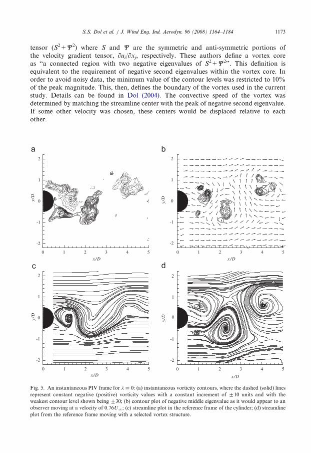
Fig. 5. An instantaneous PIV frame for l ¼ 0: (a) instantaneous vorticity contours, where the dashed (solid) lines
represent constant negative (positive) vorticity values with a constant increment of 710 units and with the
weakest contour level shown being 730; (b) contour plot of negative middle eigenvalue as it would appear to an
observer moving at a velocity of 0.76UN; (c) streamline plot in the reference frame of the cylinder; (d) streamline
plot from the reference frame moving with a selected vortex structure.
ARTICLE IN PRESSS.S. Dol et al. / J. Wind Eng. Ind. Aerodyn. 96 (2008) 1164–11841174
Fig. 5(a) depicts an instantaneous PIV frame with vorticity contours for a stationarycylinder (l ¼ 0). It can be seen that the instantaneous vorticity distribution is not circularlysymmetric about the peak, and so vorticity peaks do not coincide with vorticity centroids.Fig. 5(b) shows the corresponding contour plot of the negative second eigenvalue asit would appear to an observer moving at a velocity of 0.76UN. The upper (x/D ¼ 3.89,y/D ¼ 0.48) and lower (x/D ¼ 2.31, y/D ¼ �0.58) vortex cores in this image are moving atabout the same convective speed (within experimental uncertainty). Streamlines in thereference frame of the cylinder are shown in Fig. 5(c), where wavy streamlines areobserved, indicating a strong periodicity. Streamlines for an observer moving at theconvective speed of the vortices, are given in Fig. 5(d). The streamline-saddle arrangementfor the instantaneous frame is consistent with many ensemble-averaged fields in the nearwake (e.g., Cantwell and Coles, 1983). For the circular cylinder, the average value of
-100-50
-50
-50
50
50
50
100
150
x/D
y/D y/
Dy/
D
y/D
0 1 2 3 4 5x/D
0 1 2 3 4 5
x/D0 1 2 3 4 5
x/D0 1 2 3 4 5
-2
-1
0
1
2
-2
-1
0
1
2
-2
-1
0
1
2
-2
-1
0
1
2
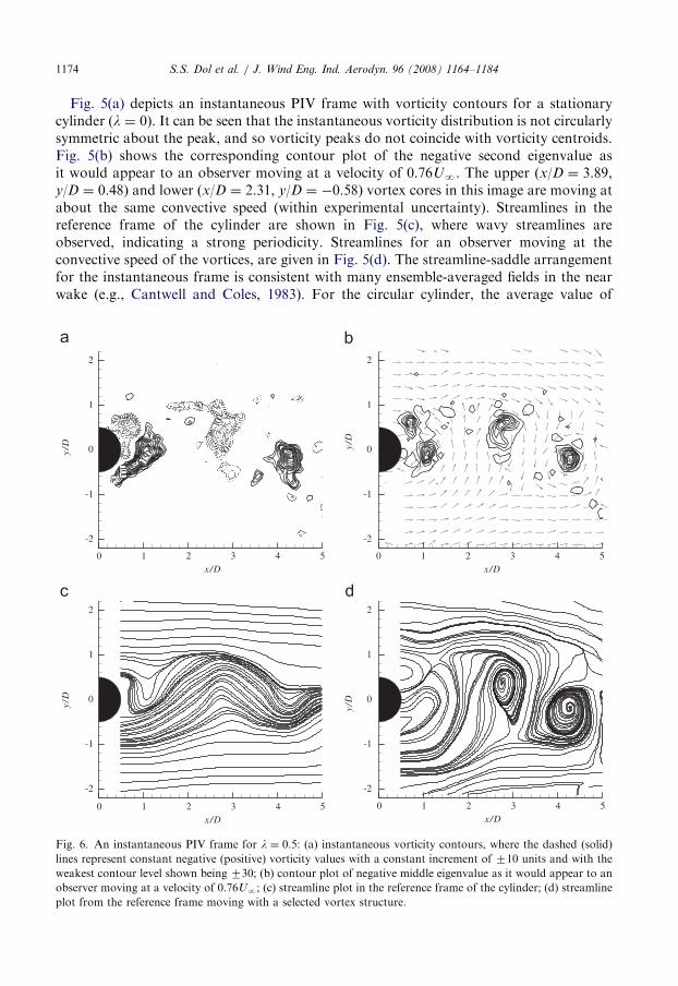
Fig. 6. An instantaneous PIV frame for l ¼ 0.5: (a) instantaneous vorticity contours, where the dashed (solid)
lines represent constant negative (positive) vorticity values with a constant increment of 710 units and with the
weakest contour level shown being 730; (b) contour plot of negative middle eigenvalue as it would appear to an
observer moving at a velocity of 0.76UN; (c) streamline plot in the reference frame of the cylinder; (d) streamline
plot from the reference frame moving with a selected vortex structure.
ARTICLE IN PRESSS.S. Dol et al. / J. Wind Eng. Ind. Aerodyn. 96 (2008) 1164–1184 1175
UC ¼ 0.76UN in the current experiments is comparable to that inferred by Cantwell andColes (1983).
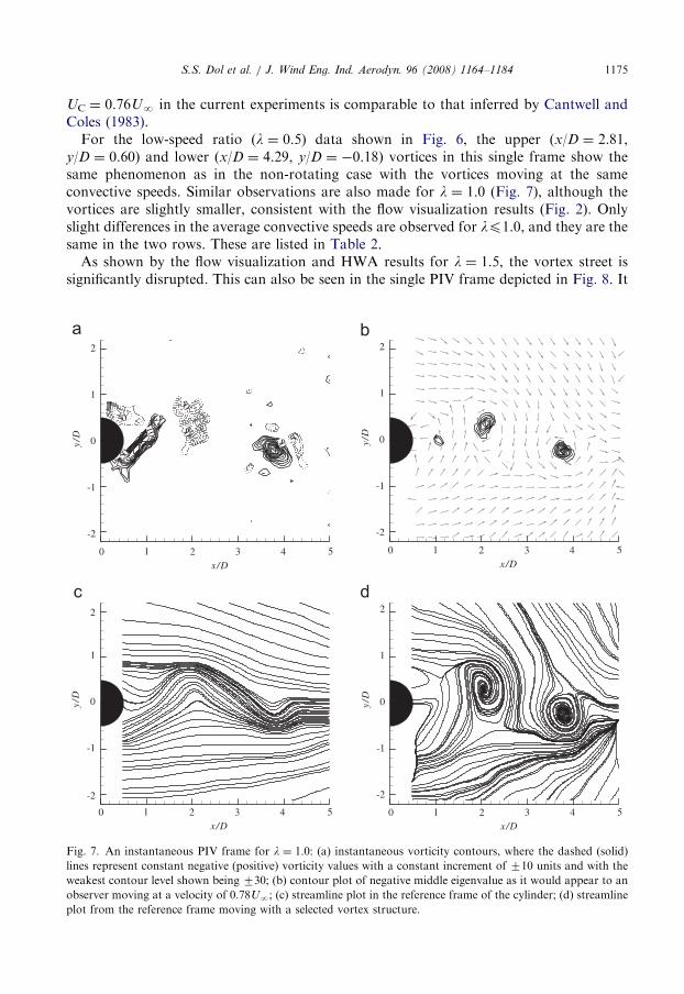
For the low-speed ratio (l ¼ 0.5) data shown in Fig. 6, the upper (x/D ¼ 2.81,y/D ¼ 0.60) and lower (x/D ¼ 4.29, y/D ¼ �0.18) vortices in this single frame show thesame phenomenon as in the non-rotating case with the vortices moving at the sameconvective speeds. Similar observations are also made for l ¼ 1.0 (Fig. 7), although thevortices are slightly smaller, consistent with the flow visualization results (Fig. 2). Onlyslight differences in the average convective speeds are observed for lp1.0, and they are thesame in the two rows. These are listed in Table 2.
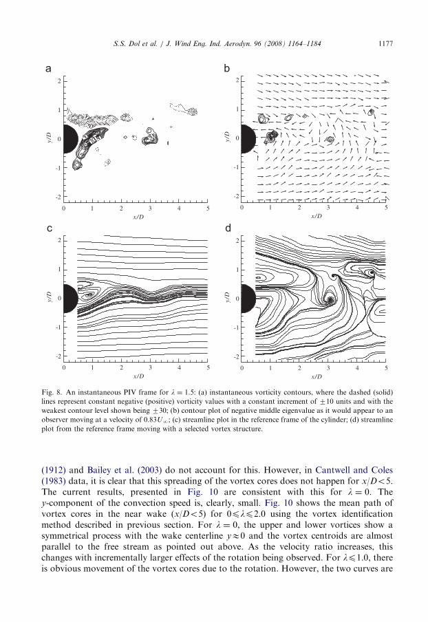
As shown by the flow visualization and HWA results for l ¼ 1.5, the vortex street issignificantly disrupted. This can also be seen in the single PIV frame depicted in Fig. 8. It
-50 -50-50
-50
50
50
50
100
x/D
y/D
0 1 2 3 4 5
-2
-1
0
1
2
x/D
y/D
0 1 2 3 4 5
-2
-1
0
1
2
x/D
y/D
0 1 2 3 4 5
-2
-1
0
1
2
x/D
y/D
0 1 2 3 4 5
-2
-1
0
1
2
Fig. 7. An instantaneous PIV frame for l ¼ 1.0: (a) instantaneous vorticity contours, where the dashed (solid)
lines represent constant negative (positive) vorticity values with a constant increment of 710 units and with the
weakest contour level shown being 730; (b) contour plot of negative middle eigenvalue as it would appear to an
observer moving at a velocity of 0.78UN; (c) streamline plot in the reference frame of the cylinder; (d) streamline
plot from the reference frame moving with a selected vortex structure.
ARTICLE IN PRESS
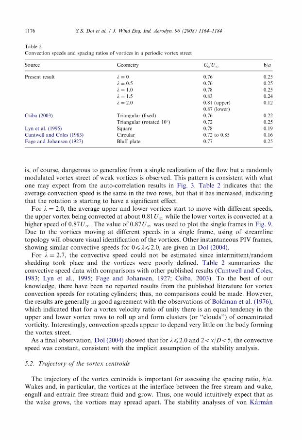
Table 2
Convection speeds and spacing ratios of vortices in a periodic vortex street
Source Geometry Uc/UN b/a
Present result l ¼ 0 0.76 0.25
l ¼ 0.5 0.76 0.25
l ¼ 1.0 0.78 0.25
l ¼ 1.5 0.83 0.24
l ¼ 2.0 0.81 (upper) 0.12
0.87 (lower)
Csiba (2003) Triangular (fixed) 0.76 0.22
Triangular (rotated 101) 0.72 0.25
Lyn et al. (1995) Square 0.78 0.19
Cantwell and Coles (1983) Circular 0.72 to 0.85 0.16
Fage and Johansen (1927) Bluff plate 0.77 0.25
S.S. Dol et al. / J. Wind Eng. Ind. Aerodyn. 96 (2008) 1164–11841176
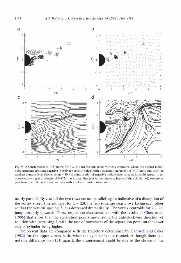
is, of course, dangerous to generalize from a single realization of the flow but a randomlymodulated vortex street of weak vortices is observed. This pattern is consistent with whatone may expect from the auto-correlation results in Fig. 3. Table 2 indicates that theaverage convection speed is the same in the two rows, but that it has increased, indicatingthat the rotation is starting to have a significant effect.For l ¼ 2.0, the average upper and lower vortices start to move with different speeds,
the upper vortex being convected at about 0.81UN while the lower vortex is convected at ahigher speed of 0.87UN. The value of 0.87UN was used to plot the single frames in Fig. 9.Due to the vortices moving at different speeds in a single frame, using of streamlinetopology will obscure visual identification of the vortices. Other instantaneous PIV frames,showing similar convective speeds for 0plp2.0, are given in Dol (2004).For l ¼ 2.7, the convective speed could not be estimated since intermittent/random
shedding took place and the vortices were poorly defined. Table 2 summarizes theconvective speed data with comparisons with other published results (Cantwell and Coles,1983; Lyn et al., 1995; Fage and Johansen, 1927; Csiba, 2003). To the best of ourknowledge, there have been no reported results from the published literature for vortexconvection speeds for rotating cylinders; thus, no comparisons could be made. However,the results are generally in good agreement with the observations of Boldman et al. (1976),which indicated that for a vortex velocity ratio of unity there is an equal tendency in theupper and lower vortex rows to roll up and form clusters (or ‘‘clouds’’) of concentratedvorticity. Interestingly, convection speeds appear to depend very little on the body formingthe vortex street.As a final observation, Dol (2004) showed that for lp2.0 and 2ox/Do5, the convective
speed was constant, consistent with the implicit assumption of the stability analysis.
5.2. Trajectory of the vortex centroids
The trajectory of the vortex centroids is important for assessing the spacing ratio, b/a.Wakes and, in particular, the vortices at the interface between the free stream and wake,engulf and entrain free stream fluid and grow. Thus, one would intuitively expect that asthe wake grows, the vortices may spread apart. The stability analyses of von Karman
ARTICLE IN PRESS
-50
-50
-50
50 50 50100
x/D
y/D
0 1 2 3 4 5
-2
-1
0
1
2
x/D
y/D
0 1 2 3 4 5
-2
-1
0
1
2
x/D
y/D
0 1 2 3 4 5
-2
-1
0
1
2
x/D
y/D
0 1 2 3 4 5
-2
-1
0
1
2
a b
c d
Fig. 8. An instantaneous PIV frame for l ¼ 1.5: (a) instantaneous vorticity contours, where the dashed (solid)
lines represent constant negative (positive) vorticity values with a constant increment of 710 units and with the
weakest contour level shown being 730; (b) contour plot of negative middle eigenvalue as it would appear to an
observer moving at a velocity of 0.83UN; (c) streamline plot in the reference frame of the cylinder; (d) streamline
plot from the reference frame moving with a selected vortex structure.
S.S. Dol et al. / J. Wind Eng. Ind. Aerodyn. 96 (2008) 1164–1184 1177
(1912) and Bailey et al. (2003) do not account for this. However, in Cantwell and Coles(1983) data, it is clear that this spreading of the vortex cores does not happen for x/Do5.The current results, presented in Fig. 10 are consistent with this for l ¼ 0. They-component of the convection speed is, clearly, small. Fig. 10 shows the mean path ofvortex cores in the near wake (x/Do5) for 0plp2.0 using the vortex identificationmethod described in previous section. For l ¼ 0, the upper and lower vortices show asymmetrical process with the wake centerline yE0 and the vortex centroids are almostparallel to the free stream as pointed out above. As the velocity ratio increases, thischanges with incrementally larger effects of the rotation being observed. For lp1.0, thereis obvious movement of the vortex cores due to the rotation. However, the two curves are
ARTICLE IN PRESS
-40
-
5050
x/D
y/D
0 1 2 3 4 5
-2
-1
0
1
2
x/D
y/D
0 1 2 3 4 5
-2
-1
1
0
2
x/D
y/D
0 1 2 3 4 5
-2
-1
1
0
2
x/Dy/
D0 1 2 3 4 5
-2
-1
0
1
2
a
c d
b
Fig. 9. An instantaneous PIV frame for l ¼ 2.0: (a) instantaneous vorticity contours, where the dashed (solid)
lines represent constant negative (positive) vorticity values with a constant increment of 710 units and with the
weakest contour level shown being 730; (b) contour plot of negative middle eigenvalue as it would appear to an
observer moving at a velocity of 0.87UN; (c) streamline plot in the reference frame of the cylinder; (d) streamline
plot from the reference frame moving with a selected vortex structure.
S.S. Dol et al. / J. Wind Eng. Ind. Aerodyn. 96 (2008) 1164–11841178
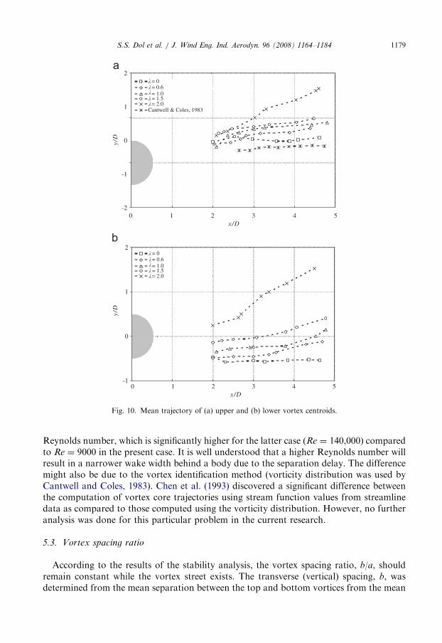
nearly parallel. By l ¼ 1.5 the two rows are not parallel, again indicative of a disruption ofthe vortex street. Interestingly, for l ¼ 2.0, the two rows are nearly overlaying each otherso that the vertical spacing, b, has decreased dramatically. The vortex centroids for l ¼ 2.0jump abruptly upwards. These results are also consistent with the results of Chew et al.(1995) that show that the separation points move along the anti-clockwise direction ofrotation with increasing l, with the rate of movement of the separation point on the lowerside of cylinder being higher.The present data are compared with the trajectory determined by Cantwell and Coles
(1983) for the upper vortex paths when the cylinder is non-rotated. Although there is anotable difference (E0.17D apart), the disagreement might be due to the choice of the
ARTICLE IN PRESS
= 0 = 0.6 = 1.0 = 1.5 = 2.0
Cantwell & Coles, 1983
�����
= 0 = 0.6 = 1.0 = 1.5 = 2.0
�����
x/D
y/D
0 1 2 3 4 5-2
-1
0
1
2
x/D
y/D
0 1 2 3 4 5-1
0
1
2
Fig. 10. Mean trajectory of (a) upper and (b) lower vortex centroids.
S.S. Dol et al. / J. Wind Eng. Ind. Aerodyn. 96 (2008) 1164–1184 1179
Reynolds number, which is significantly higher for the latter case (Re ¼ 140,000) comparedto Re ¼ 9000 in the present case. It is well understood that a higher Reynolds number willresult in a narrower wake width behind a body due to the separation delay. The differencemight also be due to the vortex identification method (vorticity distribution was used byCantwell and Coles, 1983). Chen et al. (1993) discovered a significant difference betweenthe computation of vortex core trajectories using stream function values from streamlinedata as compared to those computed using the vorticity distribution. However, no furtheranalysis was done for this particular problem in the current research.
5.3. Vortex spacing ratio
According to the results of the stability analysis, the vortex spacing ratio, b/a, shouldremain constant while the vortex street exists. The transverse (vertical) spacing, b, wasdetermined from the mean separation between the top and bottom vortices from the mean
ARTICLE IN PRESSS.S. Dol et al. / J. Wind Eng. Ind. Aerodyn. 96 (2008) 1164–11841180
trajectory of the vortex cores reported in Fig. 10. Only vortices located after the formationregion were considered once the convection speeds become constant. The early stage canbe assumed to be characterized by negligible interaction between the vortex rows. Thelongitudinal spacing was calculated by Eq. (3). The results are summarized in Table 2.Comparison of b/a to other cylinder cases reported in previous study is also made. For0plp1.5, where a periodic vortex street is observed, the spacing ratio is about 0.25.However, for l ¼ 2.0, where only weak periodicity is observed, the average spacing of theshed vortices is reduced significantly. The decrease is consistent with the almost 70%decrease in wake width from the non-rotating case (Dol, 2004). For l ¼ 2.0, the upper andlower vortices were convected at different speeds so that the average convection speed wasused in Eq. (3). Here, the average b/a�0.12. Due to poorly defined vortices and anundetectable shedding frequency, the spacing ratio for l ¼ 2.7 could not be determined(and is irrelevant).
6. Strength of shed vortices
The circulation in the vortices is related to the vorticity in the separated free shear layers.From Roshko (1954), the rate at which circulation, G, passes any plane section is
DGDt¼
U21 �U2
2
2, (4)
where U1 and U2 are the velocities at the edges of the shear layer; for the notchedhodograph theory, these are US ¼ kUN and 0, respectively, for the stationary cylindercase. The rate of circulation entering the shear layer is 1/2(k2UN) where US andk2 ¼ (1�Cpb) are the velocity just outside the boundary layer at the separation point andthe base pressure parameter, respectively, while Cpb is the base pressure. Due to only afraction of initial vorticity in the shear layers being transported to the individual vorticesfurther downstream, the relation between the circulation produced at the cylinder and thatcarried downstream by the vortices is
DGDt� f SG ¼
1
2�vk
2U21, (5)
where ev is the fraction of vorticity in the shed vortex. For a stationary cylinder, the initialcirculation G0 can be quantified from Roshko’s analysis as
G0
U1D¼
1
2St�
US
U1
� �2
. (6)
In the present experiment, for the stationary cylinder case, USE1.49UN and G0/UND ¼
5.87. This value agrees with that found by Cantwell and Coles (1983). Unfortunately, forthe case with the asymmetric separations observed in the flow past the rotating circularcylinder, we do not see any straightforward method to evaluate the circulation of the twoshear layers separately.The circulation in a vortex can be estimated as
GðxÞ ¼X
i;j
hoii;j DAi;j, (7)

ARTICLE IN PRESSS.S. Dol et al. / J. Wind Eng. Ind. Aerodyn. 96 (2008) 1164–1184 1181
where o is the spanwise vorticity, i and j are spatial indices, and A is the vortex area. Thevortex area is defined by the technique of Jeong and Hussain (1995), as described above.
The streamwise variation of G, normalized by the initial circulation, G0, discharged intothe wake during the shedding process for 0plp2.7 is plotted in Fig. 11. For l ¼ 0, themeasured circulations for shed vortices in the near wake are about 44–51% of the initialcirculation, G0, with upper and lower vortices of almost equal strength. Several previousinvestigators have observed a comparable loss of circulation. The measured circulation byCantwell and Coles (1983) for a vortex in the near wake never exceeds 44% of the totalcirculation discharged from one side of the circular cylinder during a shedding cycle. Inaddition, Lyn et al. (1995) reported that in the near wake of a square cylinder, G/G0 slowlydecays with an average rate of decay ofE10% per diameter of travel. The reduction in G isdue primarily to reduced values of vorticity. In spite of differences in Reynolds numberand geometry, as well some uncertainty about actual vortex position, there is no doubt thattypically about half of the available vorticity is lost by cancellation and interference in thebase region, where there is intense turbulent mixing of vorticity-bearing fluid from the twosides of the cylinder.
Generally, as the velocity ratio increases the magnitude of the circulation is reducedconsiderably, relative to the stationary cylinder, with the lower vortices having greaterstrengths. The fact that the vortex strength is only about 30% of the initial strength whenl ¼ 1.0 and about 4% at l ¼ 2.7 is quite amazing in terms of the engineering benefits.While it is not clear how the initial circulation varies with l, it certainly could not bereduced by this amount on both sides of the cylinder so that ev clearly depends on l as well.
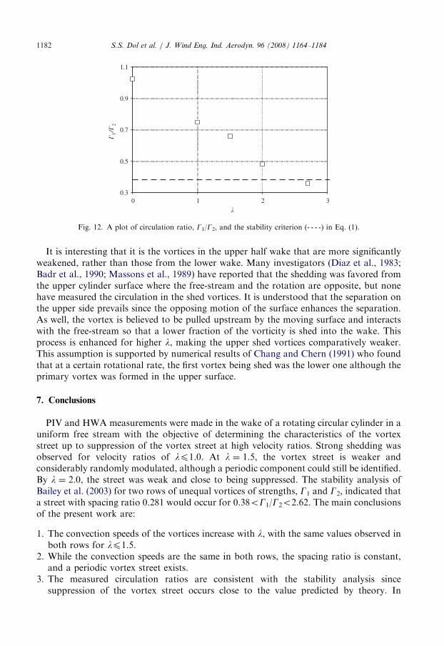
Fig. 11 depicts the ratio of circulation in the upper and lower rows of vortices, G1/G2, asa function of velocity ratio, l. The current experimental results can be compared to thestability analysis of Bailey et al. (2003), described by Eq. (1). At l ¼ 0, the ratio is nearlyequal to unity, as expected, since the top and bottom shed vortices possess equal strength.The reduction in the ratio is almost monotonic with l, inferring gradual changes in thestrength of the resulting vortices. The ratio, presented in Fig. 12, is outside the stabilitycriterion for l ¼ 2.7 and is close to it at l ¼ 2.0. This is a remarkable result, given theuncertainty in estimating vorticity from experimental data.
0.0
0.2
0.4
0.6
�/�
0
5432x/D
�= 0 (upper)
�= 0 (lower)
� = 1.0 (upper)
� = 1.0 (lower)
� = 1.5 (upper) � = 2.0 (upper)
� = 2.0 (lower)
� = 2.7 (upper)
� = 2.7 (lower)� = 1.5 (lower)
Fig. 11. The streamwise variation of the circulation in the identified vortices, G, in the two shear layers for lp2.7.
ARTICLE IN PRESS
0.3
0.5
0.7
0.9
1.1
3210
�1/�
2
�
Fig. 12. A plot of circulation ratio, G1/G2, and the stability criterion (- - - -) in Eq. (1).
S.S. Dol et al. / J. Wind Eng. Ind. Aerodyn. 96 (2008) 1164–11841182
It is interesting that it is the vortices in the upper half wake that are more significantlyweakened, rather than those from the lower wake. Many investigators (Diaz et al., 1983;Badr et al., 1990; Massons et al., 1989) have reported that the shedding was favored fromthe upper cylinder surface where the free-stream and the rotation are opposite, but nonehave measured the circulation in the shed vortices. It is understood that the separation onthe upper side prevails since the opposing motion of the surface enhances the separation.As well, the vortex is believed to be pulled upstream by the moving surface and interactswith the free-stream so that a lower fraction of the vorticity is shed into the wake. Thisprocess is enhanced for higher l, making the upper shed vortices comparatively weaker.This assumption is supported by numerical results of Chang and Chern (1991) who foundthat at a certain rotational rate, the first vortex being shed was the lower one although theprimary vortex was formed in the upper surface.
7. Conclusions
PIV and HWA measurements were made in the wake of a rotating circular cylinder in auniform free stream with the objective of determining the characteristics of the vortexstreet up to suppression of the vortex street at high velocity ratios. Strong shedding wasobserved for velocity ratios of lp1.0. At l ¼ 1.5, the vortex street is weaker andconsiderably randomly modulated, although a periodic component could still be identified.By l ¼ 2.0, the street was weak and close to being suppressed. The stability analysis ofBailey et al. (2003) for two rows of unequal vortices of strengths, G1 and G2, indicated thata street with spacing ratio 0.281 would occur for 0.38oG1/G2o2.62. The main conclusionsof the present work are:
1.
The convection speeds of the vortices increase with l, with the same values observed inboth rows for lp1.5.2.
While the convection speeds are the same in both rows, the spacing ratio is constant,and a periodic vortex street exists.3.
The measured circulation ratios are consistent with the stability analysis sincesuppression of the vortex street occurs close to the value predicted by theory. In
ARTICLE IN PRESSS.S. Dol et al. / J. Wind Eng. Ind. Aerodyn. 96 (2008) 1164–1184 1183
addition, the assumptions of the stability analysis (other than that of point vortices)appear to be justified by the current results.These results are important as they provide a possible mechanism for suppression and/or
weakening of vortex streets. Taking the current results together with the results fromBailey et al. (2003), it is clear that flow asymmetries will weaken vortex shedding, and whenthe asymmetries are significant enough, total suppression of a periodic street. This could beimportant in many applications including bridge aerodynamics where significantasymmetries are introduced due to differences in between the upper and lower surfacesof these bodies. This is currently being examined at UWO.
Acknowledgments
This research was partially funded by the Natural Science and Engineering ResearchCouncil of Canada. Equipment was obtained through grants from the Canada Foundationfor Innovation, the Ontario Innovation Trust, and the UWO Academic DevelopmentFund. S.S. Dol gratefully acknowledges the support provided by Universiti TeknologiPetronas (Malaysia) during his stay in Canada. G.A. Kopp gratefully acknowledges thesupport of the Canada Research Chairs Program.
References
Abernathy, F.H., Kronauer, R.E., 1961. The formation of vortex streets. J. Fluid Mech. 13, 1–20.
Aref, H., 1995. On the equilibrium and stability of a row of point vortices. J. Fluid Mech. 290, 167–181.
Badr, H.M., Dennis, S.C.R., Young, P.J.S., 1989. Steady and unsteady flow past a rotating circular cylinder at
low Reynolds numbers. Comput. Fluids 17, 579–609.
Badr, H.M., Coutanceau, M., Dennis, S.C.R., Menard, C., 1990. Unsteady flow past a rotating circular cylinder
at Reynolds number 103 and 104. J. Fluid Mech. 220, 459–484.
Bailey, S.C.C., 2001. The effect of wall proximity on vortex shedding from a square cylinder. M.E.Sc. Thesis,
University of Western Ontario, London, ON, Canada.
Bailey, S.C.C., Kopp, G.A., Martinuzzi, R.J., 2003. Vortex shedding from a square cylinder near a wall.
J. Turbul. 3, 1–18.
Barnes, F.H., 2000. Vortex shedding in the wake of a rotating circular cylinder at low Reynolds number. J. Phys.
D 33, L141–L144.
Bisset, D.K., Antonia, R.A., Browne, L.W.B., 1990. Spatial organization of large structures in the turbulent far
wake of a cylinder. J. Fluid Mech. 218, 439–461.
Boldman, D.R., Brinich, P.F., Goldstein, M.E., 1976. Vortex shedding from a blunt trailing edge with equal and
unequal external mean velocities. J. Fluid Mech. 75, 721–735.
Budny, R.S., Kawall, J.G., Keffer, J.F., 1979. In: Proceedings of the second Symposium on Turbulent Shear
Flows. London, England, pp. 7.20–7.25.
Cantwell, B., Coles, D., 1983. An experimental study of entrainment and transport in the turbulent near wake of a
circular cylinder. J. Fluid Mech. 136, 321–374.
Chang, C.C., Chern, R.L., 1991. Vortex shedding from an impulsively started rotating and translating circular
cylinder. J. Fluid Mech. 233, 265–298.
Chen, Y.M., Ou, Y.R., Pearlstein, A.J., 1993. Development of the wake behind a circular cylinder impulsively
started into rotary and rectilinear motion. J. Fluid Mech. 253, 449–484.
Chew, Y.T., Cheng, M., Luo, S.C., 1995. A numerical study of flow past a rotating circular cylinder using a hybrid
vortex scheme. J. Fluid Mech. 299, 35–71.
Coleman, H.W., Steele, W.G., 1989. Experimental Uncertainty Analysis for Engineers. Wiley, New York.
Csiba, A., 2003. Shedding of vortices behind a 2D triangular cylinder with connection to the Karman vortex
street. M.E.Sc. Thesis, University of Western Ontario, London, ON, Canada.
Diaz, F., Gavalda, J., Kawall, J.G., Keffer, J.F., Giralt, F., 1983. Vortex shedding from a spinning cylinder. Phys.
Fluids 26, 3454–3460.
ARTICLE IN PRESSS.S. Dol et al. / J. Wind Eng. Ind. Aerodyn. 96 (2008) 1164–11841184
Dol, S.S., 2004. The suppression of periodic vortex shedding from a rotating circular cylinder. M.E.Sc. Thesis,
University of Western Ontario, London, ON, Canada.
Fage, A., Johansen, F.C., 1927. On the flow of air behind an inclined flat plate of infinite span. Proc. R. Soc. A
116, 170.
Ferre, J.A., Giralt, F., 1989. Pattern recognition analysis of the velocity field in plane turbulent wakes. J. Fluid
Mech. 198, 27–64.
Gerrard, J.H., 1966. The mechanics of the formation region of vortices behind bluff bodies. J. Fluid Mech. 25,
401–413.
Huang, Z., Keffer, J.F., 1996. Development of structure within the turbulent wake of a porous body. Part 1. The
initial formation region. J. Fluid Mech. 329, 103–115.
Hussain, A.K.M.F., Hayakawa, M., 1987. Eduction of large-scale organized structures in a turbulent plane wake.
J. Fluid Mech. 180, 193–229.
Jeong, J., Hussain, J.F., 1995. On the identification of a vortex. J. Fluid Mech. 285, 69–94.
Kang, C., Choi, H., 1999. Laminar flow past a rotating circular cylinder. Phys. Fluids 11, 3312–3321.
Karman, T.V., 1912. Uber den mechanismus den widerstands, den ein bewegter korper in einer flussigkeit erfahrt.
Gottingen Nachr. Math. Phys. Kl. 12, 509–517.
Kochin, N.E., Kibel, I.A., Roze, N.V., 1964. Theoretical Hydrodynamics, vol. I. Wiley, London.
Kopp, G.A., Giralt, F., Keffer, J.F., 2002. Entrainment vortices and interfacial intermittent turbulent bulges in a
plane turbulent wake. J. Fluid Mech. 469, 49–70.
Laneville, A., 1990. Turbulence and blockage effects on two dimensional rectangular cylinders. J. Wind. Eng. Ind.
Aerodyn. 33, 11–20.
Lyn, D.A., Einav, S., Rodi, W., Park, J.H., 1995. A laser-Doppler velocimetry study of ensemble-averaged
characteristics of the turbulent near wake of a square cylinder. J. Fluid Mech. 304, 285–319.
Massons, J., Ruiz, X., Diaz, F., 1989. Image processing of the near wakes of stationary and rotating cylinders.
J. Fluid Mech. 204, 167–184.
Prandtl, L., 1961. Collected Works. In: Tollmien, W., Schlicting, H., Gortler, H. (Eds.). Springer, Berlin.
Roshko, A., 1954. On the drag and shedding frequency of two-dimensional bluff bodies, NACA TN No. 3169.
Shair, F.H., Grove, A.S., Petersen, E.E., Acrivos, A., 1963. The effect of confining walls on the stability of the
steady wake behind a circular cylinder. J. Fluid Mech. 17, 546–550.
Stansby, P.K., 1974. The effects of end plates on the base pressure coefficient of a circular cylinder. J. Aerosp.
78, 36.
Sung, H.J., Chun, C.K., Hyun, J.M., 1995. Experimental study of uniform shear flow of a rotating cylinder.
Trans. ASME 117, 62–67.
Swanson, W.M., 1961. The Magnus effect: a summary of investigations to date. J. Basic Eng. 83, 461–470.
Tanaka, H., Nagano, S., 1973. Study of flow around a rotating circular cylinder. Bull. JSME 16, 234–243.
Vernet, A., Kopp, G.A., 2002. Classification of turbulent flow patterns with fuzzy clustering. Eng. Appl. Artif.
Intell. 15, 315–326.
Vernet, A., Kopp, G.A., Ferre, J.A., Giralt, F., 1999. Three-dimensional structure and momentum transfer in a
turbulent cylinder wake. J. Fluid Mech. 394, 303–337.
West, G.S., Apelt, C.J., 1982. The effects of tunnel blockage and aspect ratio on the mean flow past a circular
cylinder with Reynolds number between 104 and 105. J. Fluid Mech. 114, 361–377.
Williamson, C.H.K., 1996. Vortex dynamics in the cylinder wake. Annu. Rev. Fluid Mech. 28, 477–539.
Zdravkovich, M.M., 1997. Flow Around Circular Cylinders: A Comprehensive Guide Through Flow Phenomena,
Experiments, Applications, Mathematical Models, and Computer Simulations, vol. 1: Fundamentals. Oxford
University Press, Oxford.
Zdravkovich, M.M., 2003. Flow Around Circular Cylinders: A Comprehensive Guide Through Flow Phenomena,
Experiments, Applications, Mathematical Models, and Computer Simulations, vol. 2: Applications. Oxford
University Press, Oxford.